HAZWATCH Supplement
69
The information and technical data disclosed in this document may be used and disseminated only for the purposes and to the extent specifically authorized in writing by General Monitors. Instruction Manual 11-05 General Monitors reserves the right to change published specifications and designs without prior notice. MANTS4000 Part No. MANHAZARDWATCH Revision 1/09-05 HazardWatch Integrated Fire and Gas Alarm System Supplement
-
Upload
andres-giraldo-moreno -
Category
Documents
-
view
633 -
download
11
Transcript of HAZWATCH Supplement
The information and technical data disclosed in this document may be used and disseminated only for the purposes and to the extent specifically authorized in writing by General Monitors.
Instruction Manual 11-05
General Monitors reserves the right to change published specifications and designs without prior notice.
MANTS4000 Part No. MANHAZARDWATCH Revision 1/09-05
HazardWatch Integrated Fire and Gas Alarm System
Supplement

HazardWatch
ii
This page intentionally left blank
HazardWatch
iii
Table of Contents 1.0 HAZARDWATCH SPECIFICATIONS AND DATA SHEETS ................................................. 6
1.1 Local Panel Equipment ..............................................................................................................6 1.1.1 PLC Equipment .............................................................................................................6 1.1.2 Local HMI ....................................................................................................................12 1.1.3 Communication Modules ............................................................................................14
1.1.3.1 Controlnet Module..........................................................................................14 1.1.3.2 Ethernet Module.............................................................................................15 1.1.3.3 Modbus Module..............................................................................................15
1.1.4 Fiber Optic Communication Module............................................................................16 1.1.5 DC to DC Converter ....................................................................................................16 1.1.6 DC Power Supply and Batteries .................................................................................17 1.1.7 Current Shunt and MV Transmitter .............................................................................20 1.1.8 Battery Disconnect Switch and Polarized Connectors................................................22
1.2 Coaxial Cable...........................................................................................................................24 1.3 Fiber Optic Cable .....................................................................................................................24 1.4 Central Station Equipment .......................................................................................................24
1.4.1 UL 864 Computer Station ...........................................................................................24 1.4.2 Central Station UPS....................................................................................................25 1.4.3 Central Station Fiber Optic Converter.........................................................................27 1.4.4 Central Station Printer.................................................................................................27
1.5 GMI Field Devices....................................................................................................................28 1.5.1 GM S4000C Combustible Gas Detector .....................................................................28 1.5.2 GM S4000T H2S Gas Detector ..................................................................................30 1.5.3 GM IR2100/IRFMD IR Gas Detector ..........................................................................31 1.5.4 GM IR 5000 Open Path Gas Detector ........................................................................34 1.5.5 GM FL3100/3101UV/IR Flame Detector.....................................................................35 1.5.6 GM FL3102 DFIR Flame Detector ..............................................................................37
1.6 Smoke and Thermal Fire Detection Equipment.......................................................................38 1.6.1 Pyrotronics DI-3 Ionization Type Smoke Detector......................................................38 1.6.2 Pyrotronics PE-11 Photoelectric Type Smoke Detector .............................................39 1.6.3 Pyrotronics DT-11 Thermal Detector ..........................................................................40 1.6.4 Kidde Fenwal Detect-a-fire Thermal Detector ............................................................41 1.6.5 Apollo Series 60 Ionization Type Smoke Detector .....................................................42 1.6.6 Apollo Series 60 Photoelectric Type Smoke Detector ................................................44
1.7 Audible Devices .......................................................................................................................46 1.7.1 Federal Signal Model 50 GC Selectone Horn.............................................................46 1.7.2 Federal Signal Model 300 GCX Selectone Horn ........................................................46 1.7.3 Federal Signal Model 300X & 302X Selectone Horn..................................................47 1.7.4 Federal Signal Model 41-X Selectone Horn ...............................................................48 1.7.5 MEDC XB3 Horn.........................................................................................................49 1.7.6 Notifier Spectralert Horn .............................................................................................54 1.7.7 Notifier Spectralert Horn .............................................................................................54 1.7.8 Crouse Hinds ESR Fire Alarm Bell .............................................................................54 1.7.9 Pyrotronics MBDC-6 Fire Alarm Bell...........................................................................57
1.8 Visual Devices..........................................................................................................................58 1.8.1 Federal Signal Model 191 X Strobe Light ...................................................................58 1.8.2 Federal Signal Model 151 XST Strobe Light ..............................................................58 1.8.3 Federal Signal Model 27XST Strobe Light .................................................................59
HazardWatch
iv
1.8.4 Federal Signal Model 121 X Rotating Light ................................................................60 1.8.5 MEDC XB-3 Strobe Light ............................................................................................62 1.8.6 MEDC XB-11 Strobe Light ..........................................................................................65 1.8.7 Notifier Spectralert Strobe...........................................................................................67

v
HazardWatch
HazardWatch
6
1.0 HazardWatch Specifications and Data Sheets
1.1 Local Panel Equipment
1.1.1 PLC Equipment ControlLogix Controller Specifications - 1784-CF64 Industrial CompactFlash Card Specifications:
User Available Memory: 64M bytes Nonvolatile Memory: Yes Weight: 14.2 g (0.5 oz) Operating Temperature: IEC 60068-2-1 (Test Ad, Operating Cold)
IEC 60068-2-2 (Test Bd, Operating Dry Heat) IEC 60068-2-14 (Test Nb, Operating Thermal Shock) 0 … 60°C (32 … 140°F)
Storage Temperature: IEC 60068-2-1 (Test Ab, Un-packaged Non-operating Cold) IEC 60068-2-2 (Test Bb, Un-packaged Non-operating Dry Heat) IEC 60068-2-14 (Test Na, Un-packaged Non-operating Thermal Shock) -40 … 85°C (-40 … 185°F)
Relative Humidity: IEC 60068-2-30 (Test Db, Un-packaged Non-operating Damp Heat): 5% … 95% non-condensing
Vibration: IEC60068-2-6 (Test Fc, Operating): 2g @ 10-500Hz
Operating Shock: IEC60068-2-27 (Test Ea, Unpackaged Shock): 30g
Non-Operating Shock: IEC60068-2-27 (Test Ea, Unpackaged Shock): 50g
Emissions: CISPR 11: Group 1, Class A
ESD Immunity: IEC 61000-4-2: 6kV contact discharges 8kV air discharges
Radiated RF Immunity: IEC 61000-4-3: 10V/m with 1kHz sine-wave 80%AM from 30MHz - 2000MHz 10V/m with 200Hz 50% Pulse 100%AM at 900Mhz 10V/m with 200Hz 50% Pulse 100%AM at 1890Mhz
EFT/B immunity: IEC 61000-4-4: ±4kV at 5kHz on power ports ±4kV at 5kHz on communications ports
Surge Transient Immunity: IEC 61000-4-5: ±1kV line-line (DM) and ±2kV line-earth (CM) on AC power ports
HazardWatch
7
±2kV line-earth (CM) on communications ports Conducted RF Immunity: IEC 61000-4-6:
10Vrms with 1kHz sine-wave 80%AM from 150kHz 80MHz
Enclosure Type Rating: None (open-style) Isolation Voltage: 30V
Series A controllers: Tested to withstand 500V ac for 60 seconds Series B controllers: Tested to withstand 720V dc for 60 seconds
Wiring Category*: Category 3 on communication ports Programming Cable: For 1756- CP3 or 1747-CP3 serial cable * Use this Conductor Category information for planning conductor routing. Refer to Publication 1770-4.1, Industrial Automation Wiring and Grounding Guidelines
Replacement Battery For this component: Use this battery: 1756-L1, 1756-L1M1, 1756-L1M2,
1756-L1M3 1756-BA1 (0.59g lithium)
1756-L55, 1756-L55M12,1756-L55M13, 1756-L55M14, 1756-L55M16, 1756-L55M22, 1756-L55M23, 1756-L55M24
1756-BA1 (0.59g lithium)
1756-L61/A, 1756-L62/A, 1756-L63/A 1756-L61/B, 1756-L62/B, 1756-L63/B
1756-BA1 (0.59g lithium) 1756-BA2 (0.50g lithium)
Certifications:
When marked, the components have the following certifications. See the Product Certification link at www.ab.com for Declarations of Conformity, Certificates, and other certification details.
Catalog Number Certificate Description 1756-L1 UL UL Listed Industrial Control Equipment CSA CSA Certified Process Control Equipment CSA CSA Certified Process Control Equipment for Class
I, Division 2 Group A, B, C, D Hazardous Locations CE European Union 89/336/EEC EMC Directive,
compliant with: • EN 50082-2; Industrial Immunity • EN 61326; Meas./Control/Lab., Industrial
Requirements • EN 61000-6-2; Industrial Immunity • EN 61000-6-4; Industrial Emissions
C-Tick Australian Radio communications Act, compliant with: AS/NZS CISPR 11; Industrial Emissions
EEX European Union 94/9/EC ATEX Directive, compliant with: EN 50021; Potentially Explosive Atmospheres, Protection "n" (Zone 2)
HazardWatch
8
ControlLogix Controllers Specifications:
Catalog Number: 1756-L61/B
Memory
Data and Logic: 2M bytes U/0**: 478K bytes Nonvolatile Memory Yes***
Backplane
@ 5.1V dc: 1.20A @ 24V dc: 14mA Power Dissipation: 3.5 Thermal Dissipation: 11.9 BTU/hr Weight: 0.35 kg (12.4 oz)
*Data and logic memory stores: tags other than I/0, produced, or consumed tags; logic routines; and communication with OPC/DDE tags that use RSLinx software (also uses I/O memory)
**I/O memory stores: I/O tags, produced tags, consumed tags, communication via Message (MSG) instructions, communication with workstations, and communication with OPC/DDE tags that use RSLinx software (also uses data and logic memory).
***Requires a 1784-CF64 Industrial CompactFlash card.
1756-OB16D Specifications:
Number of Outputs: 16 (8 points/common) Module Location: 1756 ControlLogix Chassis Backplane Current: 250mA @ 5.1V dc & 140mA @ 24V dc
(Total backplane power 4.64W) Max. Power Dissipation (Module): 3.3W @ 60oC Thermal Dissipation: 11.25 BTU/hr Output Voltage Range: 19.2-30V dc Output Current Rating Per Point: Per Module:
2A max. @ 30°C & 1A max. @ 60°C (Linear derating) 8A max. @ 30°C & 4A max. @ 60°C (Linear derating)
Surge Current per Point: 4A for 10ms each, repeatable every 1s Minimum Load Current: 3mA per point Maximum On-State Voltage Drop: 1.2V dc @ 2A Max. Off-State Leakage Current: 1mA per point Output Delay Time OFF to ON: ON to OFF:
1ms maximum 5ms maximum
Diagnostic Functions: Short trip:
8A 180ms minimum 10A 120ms minimum
No load: OFF STATE detection only Output verification: ON STATE detection only Pulse test: User selectable maximum pulse width
HazardWatch
9
Time stamp of diagnostics: +/- 1ms Configurable Fault States/Point: Hold Last State, ON or OFF (OFF is the default) Configurable States in Program: Hold Last State, ON or OFF (OFF is the default) Mode/Point Scheduled Outputs: Synchronization within 16.7s maximum, reference
to the Coordinated System Time Fusing: Electronically fused per point Reverse Polarity Protection: None - If module is wired incorrectly, outputs may
be damaged. Isolation Voltage Group to group: 100% tested at 2546V dc for 1s (250V ac max.
continuous voltage between groups) User to system: 100% tested at 2546V dc for 1s RTB Screw Torque (Cage clamp): 4.4 inch-pounds (0.4Nm) maximum Module Keying (Backplane): Software configurable RTB Keying: User defined mechanical keying RTB and Housing: 36 Position RTB (1756-TBCH or TBS6H)1 Environmental Conditions Operating Temperature: 0 to 60°C (32 to 140°F) Storage Temperature: -40 to 85°C (-40 to 185°F) Relative Humidity: 5 to 95% non-condensing Conductors Wire Size: 2-14-gauge (2mm2) stranded 1
3/64 inch (1.2mm) insulation maximum Category: 12, 3 Screwdriver Blade Width for RTB: 1/8 inch (3.2mm) maximum Agency Certification: (When product or packaging is marked)
UL -Listed Industrial Control Equipment CSA - Approved Class I, Division 2, Group A, B, C, D FM - Approved Class I, Division 2, Group A, B, C, D CE - Marked for all applicable directives
Maximum wire size will require extended housing - 1756-TBE.
Use this conductor category information for planning conductor routing as described in the system level installation manual.
Refer to publication 1770-4.1 “Industrial Automation Wiring and Grounding Guidelines.
NOTE: The ControlLogix system must be mounted within a suitable enclosure to prevent personal injury resulting from accessibility to live parts. The interior of this enclosure must be accessible only by the use of a tool.
1756-IB32, Input Module Specifications:
Number of Inputs: 32 (16 points/common) Module Location: 1756 ControlLogix Chassis Backplane Current: 150mA @ 5.1V dc & 2mA @ 24V dc (Total
backplane power 0.81W)
Maximum Power Dissipation
(Module): 4.5W @ 60oC
HazardWatch
10
Thermal Dissipation: 16.37 BTU/hr @ 60oC On-State Voltage Range: 10-31.2V dc Nominal Input Voltage: 24V dc
ON-State Current
@ 10V dc: 2.mA @ 31.2V dc: 5.5mA Maximum Off-State Voltage: 5V dc Maximum Off-State Current: 1.5mA Maximum Input Impedance @ 31.2V dc: 5.67kΏ
Input Delay Time
OFF to ON: Programmable filter:0ms, 1ms or 2ms Hardware delay: 1ms maximum plus filter time ON to OFF: Programmable filter: 0ms, 1ms, 2ms, 9ms or 18ms Hardware delay: 2ms maximum plus filter time
Diagnostic Functions
Change of state: Software configurable Time stamp on inputs: +/- 200µs Short/Inrush Current: 250mA peak (decaying to <37% in 22ms, without
activation) Cyclic Update Time: User selectable (100_s minimum/750ms maximum)Reverse Polarity Protection: Yes
Isolation Voltage
Group to group: 250V maximum continuous/100% tested at 2546V dc for 1s
User to system: 250V maximum continuous/100% tested at 2546V dc for 1s
RTB Screw Torque (Cage clamp): 4.4 inch-pounds (0.4Nm) maximum Module Keying (Backplane): Software configurable RTB Keying: User defined mechanical keying Field Wiring Arm and Housing: 36 Position RTB (1756-TBCH or TBS6H)(1)
Environmental Conditions
Operating Temperature: IEC 60068-2-1 (Test Ad, Operating Cold) IEC 60068-2-2 (Test Bd, Operating Dry Heat) IEC 60068-2-14 (Test Nb, Operating Thermal Shock) 0 to 60°C (32 to 140°F)
Storage Temperature: IEC 60068-2-1 (Test Ab, Un-packaged Non-operating Cold) IEC 60068-2-2 (Test Bb, Un-packaged Non-operating Dry Heat), IEC 60068-2-14 (Test Na, Un-packaged Non-operating Thermal Shock): –40 to 85°C (–40 to 185°F)
Relative Humidity: IEC 60068-2-30 (Test Db, Un-packaged Non-operating Damp Heat): 5 to 95% non-condensing
Vibration: IEC60068-2-6 (Test Fc, Operating):
HazardWatch
11
2g @ 10-500Hz Shock: IEC60068-2-27 (Test Ea Unpackaged shock): Operating: 30g Non-operating: 50g Emissions: CISPR 11: Group 1, Class A ESD Immunity: IEC 61000-4-2:
6kV contact discharges 8kV air discharges
Radiated RF Immunity: IEC 61000-4-3: 10V/m with 1kHz sine-wave 80%AM from 30MHz to 1000MHz 10V/m with 200Hz 50% Pulse 100%AM at 900Mhz
EFT/B Immunity: IEC 61000-4-4: ±4kV at 2.5kHz on power ports ±4kV at 2.5kHz on signal ports
Surge Transient Immunity: IEC 61000-4-5: ±1kV line-line (DM) and ±2kV line-earth (CM) on power ports ±1kV line-line (DM) and ±2kV line-earth (CM) on signal ports
Conducted RF Immunity: IEC 61000-4-6: 10Vrms with 1kHz sine-wave 80%AM from 150kHz to 80MHz
Enclosure Type Rating: None (open-style) Conductors - Wire Size: #22 to #14 AWG (0.324 to 2.08 sq. mm) stranded1
3/64 inch (1.2mm) insulation maximum Category: 12, 3 Screwdriver Blade Width for RTB: 1/8 inch (3.2mm) maximum Certifications: (When product is marked)
UL -UL Listed Industrial Control Equipment CSA -CSA Certified Process Control Equipment CSA -CSA Certified Process Control Equipment for Class I, Division 2 Group A, B, C, D Hazardous Locations FM- FM Approved Equipment for use in Class I Division 2 Group A, B, C, D Hazardous Locations CE4 -European Union 89/336/EEC EMC Directive, compliant with: EN 50082-2; Industrial Immunity EN 61326; Meas./Control/Lab., Industrial Requirements EN 61000-6-2; Industrial Immunity EN 61000-6-4; Industrial Emissions C-Tick4 Australian Radio communications Act, compliant with: AS/NZS 2064; Industrial Emissions EEx4 European Union 94/9/EEC ATEX Directive, compliant with: EN 50021; Potentially Explosive Atmospheres, Protection “n”
1. Maximum wire size will require extended housing - 1756-TBE.
2. Use this conductor category information for planning conductor routing as described in the
HazardWatch
12
system level installation manual.
3. Refer to publication 1770-4.1 Industrial Automation Wiring and Grounding Guidelines.
4. See the Product Certification link at www.ab.com for Declarations of Conformity, Certificates, and other certification details.
ControlLogix ControlNet Bridge 1756-CNBR Specifications:
ControlNet Interface
Connectors: 2 BNC connectors for redundant media operation 1 NAP (RJ-45 8-pin with shield)
Cable: Quad shield RG-6 coaxial cable Ground isolation: Transformer
Electrical
Power dissipation: 5.14 W Thermal dissipation: 17.5 BTU/hr Backplane current: 1.0 A @ 5.1 V
1.7 mA @ 24 V
Environmental
Operational temperature: 0 to 60°C (32 to 140°F) Storage temperature: –40 to 85°C (–40 to 185°F) Relative humidity: 5 to 95% (without condensation)
Physical
Location: Any slot in a 1756 chassis Weigh: 0.260 kg (0.57 lb.) 0.293 kg (0.64 lb.)
Agency Certification
(When product or packaging is marked) UL -Listed Industrial Control Equipment CSA -Approved Class I, Division 2, Group A, B, C,
D FM - Approved Class I, Division 2, Group A, B, C,
D CE -Marked for all applicable directives
1.1.2 Local HMI PanelView Plus 1000 Specifications:
Display Size: 10.4 in Type: Color active matrix thin film transistor (TFT) Resolution: 640 x 480, 24 bit color Input Method: Keypad, touch, or combination keypad/touch
Communication Options
Flash Memory: Standard: 32 MB; extended: 128 MB RAM: Standard: 64 MB; extended: 128 MB I/O and Slots: 1 serial port, 2 USB ports, 1 10/100 Mbps Ethernet
port, 1 Compact Flash memory card slot Input Voltage: DC: 18-32V dc
HazardWatch
13
Operating Temperature
Storage Temperature: 25...70°C (13...158°F) Humidity: 5...95%, non-condensing @ 0...55°C
Vibration – Operating
Non Operating: 0.012 in pp, 10…57 Hz, 2g peak, 57…500 Hz
Shock – Operating/
Non-Operating: 15g/30g Ratings: NEMA Type 12, 13, 4X*, IP54, IP65 Certifications: UL, C-UL approved; Class 1/2/3 - Div 2 Groups A,
B, C, D; CE marked
Mechanical
Weight: Touch: 2.6 kg (5.7 lb.) 2.9 kg (6.3 lb.)
Dimensions Overall
(H x W x D): Touch only: 248 x 329 x 55 mm (9.77 x 12.97 x 2.17 in) Keypad or Keypad/Touch: 248 x 399 x 55 mm (9.77 x 15.72 x 2.17 in)
Cutout Dimensions Touch only: 224 x 305 mm (8.8 x 12 in) Keypad or Keypad/Touch: 224 x 375 mm (8.8 x 14.75 in)
PanelView Plus Specifications:
PanelView Plus 1000 Display Size: 10.4 in Type: Color active matrix thin film transistor (TFT) Resolution: 640 x 480, 24 bit color Input Method: Keypad, touch, or combination keypad touch Communication Options:
ControlNet, DH+, Remote I/O, DH485, DF1 Ethernet/IP, and user configurable non-RA networks
Flash Memory: Standard: 32 MB; extended: 128 MB RAM: Standard: 64 MB; extended: 128 MB I/O and Slots: 1 serial port, 2 USB ports, 1 10/100 Mbps Ethernet port, 1 Compact
Flash memory card slot Input Voltage: DC: 18-32V dc Operating Temperature:
0...55°C (32...131F)
Storage Temperature:
-25...70°C (-13...158°F)
Humidity: 5...95%, non-condensing @ 0...55°C Vibration – Operating and Non-Operating:
0.012 in p-p, 10…57 Hz, 2g peak, 57…500 Hz
Shock – Operating and Non-Operating
15g/30g
HazardWatch
14
Ratings: NEMA Type 12, 13, 4X*, IP54, IP65 Certifications: UL, C-UL approved; Class 1/2/3
Touch: 2.6 kg (5.7 lb.) Mechanical Weight
Keypad or Keypad/Touch: 2.9 kg (6.3 lb.)
Touch only: 248 x 329 x 55 mm
(9.77 x 12.97 x 2.17 in)
Dimensions Overall (H x W x D)
Keypad or Keypad/Touch: 248 x 399 x 55 mm
(9.77 x 15.72 x 2.17 in) Touch only:
224 x 305 mm (8.8 x 12 in)
Cutout Dimensions
Keypad or Keypad/Touch: 224 x 375 mm (8.8 x 14.75 in)
1.1.3 Communication Modules
1.1.3.1 Controlnet Module
Module 1756-CNBR Specifications:
ControlNet Interface connectors 2 BNC connectors for redundant media operation 1 NAP (RJ-45 8-pin with shield)
Cable Quad shield RG-6 coaxial cable Ground isolation Transformer
Electrical
Power dissipation 5.14 W Thermal dissipation 17.5 BTU/hr Backplane current 1.0 A @ 5.1 V
1.7 mA @ 24 V V
Environmental
Operational temperature 0 to 60°C (32 to 140°F) Storage temperature –40 to 85°C (–40 to 185°F) Relative humidity 5 to 95% (without condensation)
Physical
Location: Any slot in a 1756 chassis Weight: 0.293 kg (0.64 lb.) Agency Certification (When product or packaging is marked)
Listed Industrial Control Equipment Certified Process Control Equipment Certified Class I, Division 2, Group A, B, C, D Marked for all applicable directives Marked for all applicable acts Approved class I, Division 2, Group A, B, C, D
HazardWatch
15
1.1.3.2 Ethernet Module
Specifications:
Module Location: Any slot in the ControlLogix chassis Maximum Backplane Current Load: 700mA @ 5.1V DC 3mA @ 24V DC from I/O chassis
backplane Power Dissipation: 3.65W maximum Shock (Unpackaged) 30g operational
50g non-operational Vibration (Unpackaged) 5g from 10 to 150 Hz Conductors Wiring Category 802.3 compliant - twisted pair
2(1) Ethernet Connector RJ45 Category 5 User Manual Publication 1756-UM050 Agency Certifications When product is marked Listed Industrial Control Equipment
Certified Process Control Equipment Certified Class I, Division 2, Groups A, B, C, D Marked for all applicable directives Marked for all applicable acts Approved Class I, Division 2, Groups A,B,C,D N223
Environmental
Operating Temperature 0 to 60° C (32 to 140° F) Storage Temperature -40 to 85° C (-40 to 185° F) Relative Humidity 5 to 95%, non-condensing
1.1.3.3 Modbus Module
Modbus Master/Slave Communications Interface Module
MVI56-MCM
Specifications:
Local or Remote Rack
Backplane Current Load: 800 mA @ 5 V Operating Temperature: 0 to 60 Deg C (32 to 140 Deg F) Storage Temperature: -40 to 85 Deg C (-40 to 185 Deg F) Shock: 30g Operational
50g non-operational Vibration: 5 g from 10 - 150 Hz Relative Humidity: 5-95% (w/o condensation) LED Indicators: Module Status
Backplane Transfer Status Application Status Serial Activity and Error LED Status
Configuration Serial Port (PRT1): DB-9M PC Compatible RS-232 only Hardware handshaking
HazardWatch
16
Application Serial ports (PRT1, PRT2):
RJ45 (RJ45 to DB-9M PC Compatible connector is supplied) RS232/422/485 jumper selectable RS232 handshaking configurable 500V Optical isolation from backplane
1.1.4 Fiber Optic Communication Module PheonixDigital Specifications:
Fiber Optic Cable Type: Multimode or Singlemode Mating Connector: ST or SMA Transmit Launch Power: 15dbm (Typical, Multimode); -18dbm (Singlemode) Receive Sensitivity: -32dbm
Power Supply
Plug-In Modules: +5 VDC, 1.8 Amps (Typical Standalone Panelmount Modules: 120/220 VAC, 24 VDC, or 125 VDC.... 10 Watts
Environmental
Operating Temperature: 0° to 60° C (32° to 140° F) Storage Temperature: -40° to 85° C (-40° to 185° F) Relative Humidity: 0 to 95% RH, non-condensing
Dimensions
1771 Plug-In Modules: Single Slot, 1771 Chassis Installation 1746 Plug-In Modules: Single Slot, 1746 Chassis Installation 1756 Plug-In Modules: Single Slot, 1756 Chassis Installation Standalone, Panelmount: 10.38” H x 1.76” W* x 6.14” D Modules: (26.36cm H x 4.47cm W* x 15.60cm D
* Add 1.00” (2.54cm) for rear panel flange
1.1.5 DC to DC Converter Cosel Power Module CBS100 Specifications:
Isolation
Input Output DC1, 500V, or AC1, 000V 1 minute, Cutoff current = 10 mA, DC500V 50 ML2 min (20±15°C)
Input Case Pin, Base Plate DC1, 500V, or AC1, 000V 1 minute, Cutoff current = 10 mA, DC500V 50 ML2 min (20±15°C)
Output Case Pin, Base Plate AC500V 1minute, Cutoff current 10mA, DC500V 50 ML2 min (20±15°C)
Environment
Operating Temp. Humid and Altitude -40 to 100°C (On aluminum base plate), 20 – 95% RH (Non condensing) (Refer to DERATING
HazardWatch
17
CURVE), 3,000m (10,000 feet) max
Storage Temp, Humid and Altitude -40 to 100°C, 20 – 95% RH (Non condensing), 9,000m (30,000 feet) max
Vibration 10-55 Hz, 49.0m/s2 (5G), 3 minutes period, 60 minutes each along X, Y, and Z axis
Impact 196.1 m/s2 (20G), 11ms, once each along X, Y, and Z axis
Safety
Agency Approvals UL60950, C-UL, EN60950
Others
Case Size/Weight 57.9 x 12.7X 61.0mm (WX HXD)/83g max Cooling Method Conduction cooling (e.g. heat radiation from the
aluminum base plate to the attached heat sink)
1.1.6 DC Power Supply and Batteries LaMarche Power Supply /Battery Charger Specifications:
Electrical
AC Input Voltages: Single Phase 60Hz: 120,208,240,480 or 575 Single Phase 50Hz: 220/240,380 or 415 Three Phase 60Hz: 208,240,480 or 575 Three Phase 50Hz: 220/240,380 or 415
Output Power Protection: DC Fuse, DC Voltage Regulation and Current Limit Protection
DC Output Voltages: DC Amps: 3 to 400 amperes DC Volts: 12, 24, 48 & 130VDC (Others available such as 32 & 36VDC)
Output Filtering: 30mV RMS for single phase models and 100mV RMS for three-phase models when connected to a battery with an ampere-hour capacity of four times the output current capacity of the charger.
DC Voltage Regulation: Plus or minus 0.5% of setting from no load to full load over the specified input voltage, frequency and ambient temperature ranges.
Environmental
Operating Temperature: 0 to 50O C (32 to 122O F) Storage Temperature: -40 to 85O C (-40 to 185O F) Relative Humidity: 0 to 95% (non-condensing)
Dimensions: Overall dimensions and weights are listed here-in. Case specifications are subject to change due to innovative product development and design. When space requirements are critical, please consult the factory.
Mounting: Floor or wall units are available. Mounting flanges
HazardWatch
18
are supplied as integral part of cabinet back plate on wall mounted models.
Finish: Pretreated with three-step iron phosphate wash and de-ionized rinse. Finished with environmentally safe water based ANSI 61 gray baked enamel.
Agency Approvals
U.L. Industrial Battery Charger: File E 25701,Guide BBHZ Std.No.1564 U.L. Fire Alarm System / Power Supply Application:
File S2768, Guide UTRZ Std.No. 1481
CSA Rectifiers: File LR14209, Std. C22.2 No. 107
UPS12-370 – Specifications:
Cells Per Unit 6 Voltage Per Unit 12.84 Weight 74 lbs, 34 kg. Electrolyte Absorbed H2SO SG = 1.300 Max. Discharge Current 800 Amps Short Circuit Current 5100Amps @ 0.1 sec Ohms Imped. 60 Hz Ω 0.0025 Ohms Capacity 391 watts per cell at the 15-minute rate to 1.67
volts per cell at 77°F (25°C). 100 Ah @ 20 hr. rate to 1.75 volts per cell @ 77°F (25°C). 85 Ah @ 10 hr. rate to 1.80 volts per cell @ 20°C (68°F).
Operating Temperature Range Discharge; -40°F (-40°C) to +160°F (71°C). Charge; -10°F (-23°C) to + 140°F (60°C). (with temperature compensation)
Nominal Operating Temperature Range +74°F (23°C) to +80°F (27°C) Float Charging Voltage 13.5 to 13.8 VDC/unit Average at 77°F (25°C) Recommended Maximum Charging Current Limit
C/5 amperes (20 amperes @ 100% depth of discharge) @ 20 hour rate.
Equalization and Cycle Service Charging Voltage
14.4 to 14.8 VDC/unit Average at 77°F (25°C)
Maximum AC Ripple (Charger) 0.5% RMS or 1.5% P-P of float charge voltage recommended for best results Maximum voltage allowed = 1.4% RMS (4% P-P) Maximum current allowed = 5 amperes RMS (C/20)
Self Discharge Dynasty UPS batteries may be stored for up to 6 months at 77°F (25°C) and then a freshening charge is required. For higher temperatures the time interval will be shorter.
Accessories Inter unit connectors; racks and cabinet systems are available.
Terminal "L" terminal with 0.28" clearance hole to accept 0.25" (6mm) bolt.
Terminal Hardware Initial Torque 65 in.-lbs. (7.4 N-m). Terminal Hardware Annual Retorque 52 in.-lbs. (5.88 N-m).
HazardWatch
19
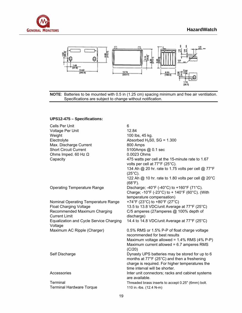
NOTE: Batteries to be mounted with 0.5 in (1.25 cm) spacing minimum and free air ventilation. Specifications are subject to change without notification.
UPS12-475 – Specifications:
Cells Per Unit 6 Voltage Per Unit 12.84 Weight 100 lbs, 45 kg. Electrolyte Absorbed H2S0, SG = 1.300 Max. Discharge Current 800 Amps Short Circuit Current 5100Amps @ 0.1 sec Ohms Imped. 60 Hz Ω 0.0023 Ohms Capacity 475 watts per cell at the 15-minute rate to 1.67
volts per cell at 77°F (25°C). 134 Ah @ 20 hr. rate to 1.75 volts per cell @ 77°F (25°C). 122 Ah @ 10 hr. rate to 1.80 volts per cell @ 20°C (68°F).
Operating Temperature Range Discharge; -40°F (-40°C) to +160°F (71°C). Charge; -10°F (-23°C) to + 140°F (60°C). (With temperature compensation)
Nominal Operating Temperature Range +74°F (23°C) to +80°F (27°C) Float Charging Voltage 13.5 to 13.8 VDC/unit Average at 77°F (25°C) Recommended Maximum Charging Current Limit
C/5 amperes (27amperes @ 100% depth of discharge)
Equalization and Cycle Service Charging Voltage
14.4 to 14.8 VDC/unit Average at 77°F (25°C)
Maximum AC Ripple (Charger) 0.5% RMS or 1.5% P-P of float charge voltage recommended for best results Maximum voltage allowed = 1.4% RMS (4% P-P) Maximum current allowed = 6.7 amperes RMS (C/20)
Self Discharge Dynasty UPS batteries may be stored for up to 6 months at 77°F (25°C) and then a freshening charge is required. For higher temperatures the time interval will be shorter.
Accessories Inter unit connectors; racks and cabinet systems are available.
Terminal Threaded brass inserts to accept 0.25" (6mm) bolt. Terminal Hardware Torque 110 in.-lbs. (12.4 N-m)
HazardWatch
20
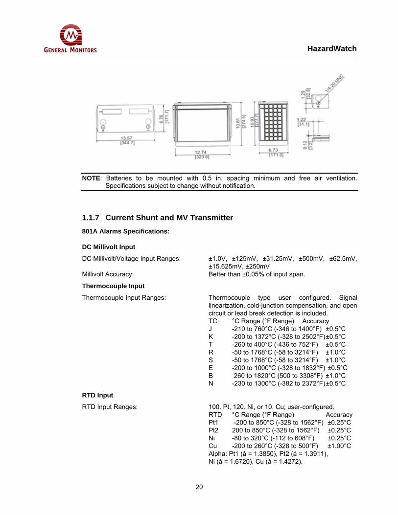
NOTE: Batteries to be mounted with 0.5 in. spacing minimum and free air ventilation. Specifications subject to change without notification.
1.1.7 Current Shunt and MV Transmitter 801A Alarms Specifications:
DC Millivolt Input
DC Millivolt/Voltage Input Ranges: ±1.0V, ±125mV, ±31.25mV, ±500mV, ±62.5mV, ±15.625mV, ±250mV
Millivolt Accuracy: Better than ±0.05% of input span.
Thermocouple Input
Thermocouple type user configured. Signal linearization, cold-junction compensation, and open circuit or lead break detection is included.
Thermocouple Input Ranges:
TC °C Range (°F Range) Accuracy J -210 to 760°C (-346 to 1400°F) ±0.5°C K -200 to 1372°C (-328 to 2502°F) ±0.5°C T -260 to 400°C (-436 to 752°F) ±0.5°C R -50 to 1768°C (-58 to 3214°F) ±1.0°C S -50 to 1768°C (-58 to 3214°F) ±1.0°C E -200 to 1000°C (-328 to 1832°F) ±0.5°C B 260 to 1820°C (500 to 3308°F) ±1.0°C N -230 to 1300°C (-382 to 2372°F) ±0.5°C
RTD Input
RTD Input Ranges: 100. Pt, 120. Ni, or 10. Cu; user-configured. RTD °C Range (°F Range) Accuracy Pt1 -200 to 850°C (-328 to 1562°F) ±0.25°C Pt2 200 to 850°C (-328 to 1562°F) ±0.25°C Ni -80 to 320°C (-112 to 608°F) ±0.25°C Cu -200 to 260°C (-328 to 500°F) ±1.00°C Alpha: Pt1 (á = 1.3850), Pt2 (á = 1.3911), Ni (á = 1.6720), Cu (á = 1.4272).
HazardWatch
21
2, 3, or 4-wire configurations supported. Module provides sensor excitation, linearization, lead-wire compensation, and sensor break detection
RTD Excitation Current: 1mA DC typical, all types RTD Lead-Wire Compensation: 25 ohms per lead RTD Break Detection: Configurable for either upscale or downscale
Resistance Input
Resistance Input Range: 0 to 500 ohms. Resistance Accuracy: ±0.05 ohms.
Output
Relay (801A-0100 models) One DPDT electro-mechanical relay. Contact material Silver Nickel (AgNi 90/10).
Relays (801A-0200 models) Two independent SPDT electro-mechanical relays. Contact material Silver-Cadmium Oxide (AgCdO).
Relay Ratings (CSA ratings) 25V DC @ 5A. 120/240V AC @ 5A. Expected Mechanical Life 20 million operations.
Environmental
Ambient Temperature Operating: 25 to 70°C (-13 to 158°F) Storage: 40 to 85°C (-40 to 185°F) Relative Humidity: 5 to 95%.
Power Requirements: 10 to 36V DC. 55mA @ 24V. 75mA @ 15V. Isolation: 3-way (input/output/power). 1500V AC for 60
seconds or 250V AC continuous. Radiated Field Immunity (RFI): EN61000-4-3, EN50082-1. Electromagnetic Field Immunity (EMI): No relay trips will occur beyond ±0.25% of input
span from set point under the influence of electromagnetic fields from switching solenoids, commutator motors, and drill motors.
Electrical Fast Transient (EFT): EN61000-4-4, EN50082-1. Surge Withstanding Capability (SWC): EN61000-4-5, EN50082-1. Electrostatic Discharge (ESD): EN61000-4-2, EN50082-1. Radiated Emissions: EN50081-1 for Class B equipment.
Approvals: CE marked, UL, cUL listed (USA, Canada). UL3121 - general product safety.
Configuration
Software Configuration: Units are fully programmable via the Windows 95/98/ME/2000/NT/XP IntelliPack Configuration Program. Configuration downloads from PC through EIA232 serial port using Acromag 800C-SIP kit.
Field Configuration: Set point and deadband are configurable via push-buttons and a standard calibrator.
LED Indicators: LEDs indicate power, status, and alarm.
Physical
HazardWatch
22
Enclosure Case: Self-extinguishing NYLON type 6.6 polyamide
thermoplastic UL94 V-2, color beige; general-purpose NEMA Type 1 enclosure.
Connectors (Removable terminal blocks): Wire Range: AWG #14-22 (AWG #12 stranded only).
Printed Circuit Boards: Military grade FR-4 epoxy glass circuit board. Dimensions: 1.05W x 4.68H x 4.35D inches. 26.7W x 118.9H x
110.5D millimeters. Shipping Weight: 1 pound (0.45 Kg) packed.
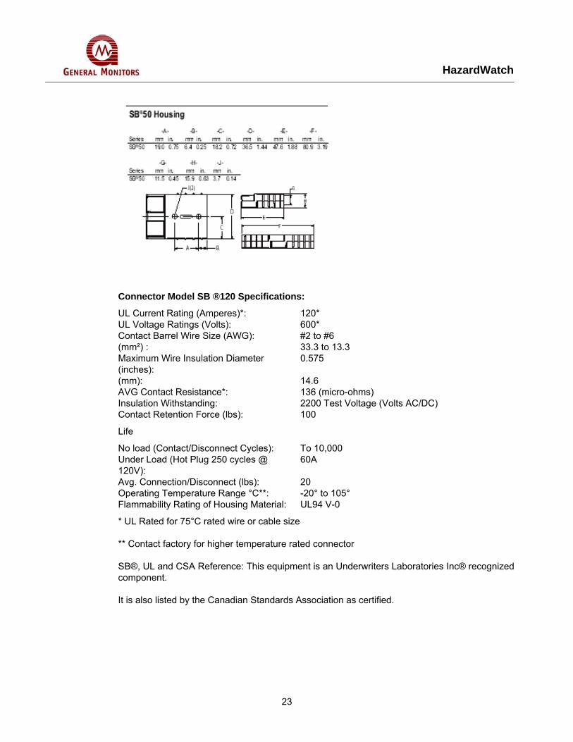
1.1.8 Battery Disconnect Switch and Polarized Connectors Connector Model SB ®50 Specifications:
UL Current Rating (Amperes)*: 50* UL Voltage Ratings (Volts): 600* Contact Barrel Wire Size (AWG): #6 to #16 (mm²): 13.3 to 1.3 Maximum Wire Insulation Diameter (inches):
0.44
(mm): 11.18 AVG Contact Resistance*: 200 (micro-ohms) Insulation Withstanding: 2200 Test Voltage (Volts AC/DC) Contact Retention Force (lbs): 50
Life
No load (Contact/Disconnect Cycles): To 10,000
Under Load (Hot Plug 250 cycles @ 120V):
50A
Avg. Connection/Disconnect –high detent:
15(lbs)
With lower extraction force: 10(lbs) Operating Temperature Range °C**: 20° to 105° Flammability Rating of Housing Material UL94 V:
0
* UL Rated for 75°C rated wire or cable size
** Contact factory for higher temperature rated connector
SB®, UL and CSA Reference: This equipment is an Underwriters Laboratories Inc® recognized component.
It is also listed by the Canadian Standards Association as certified.
HazardWatch
23
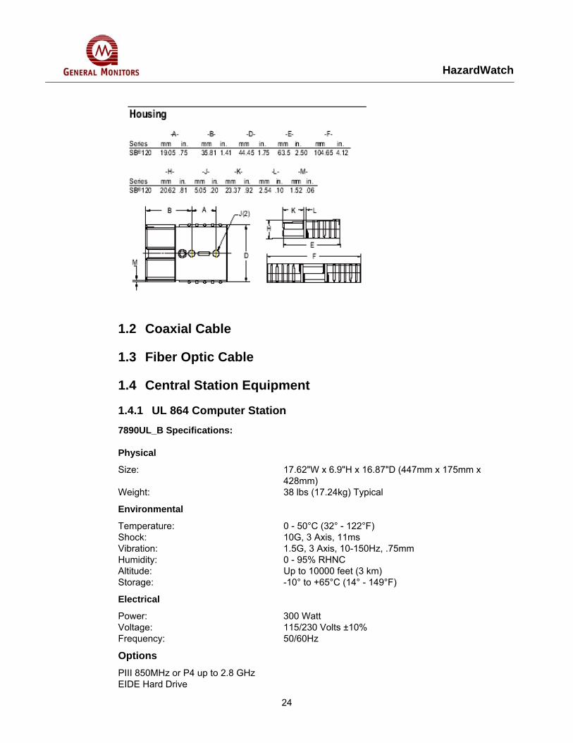
Connector Model SB ®120 Specifications:
UL Current Rating (Amperes)*: 120* UL Voltage Ratings (Volts): 600* Contact Barrel Wire Size (AWG): #2 to #6 (mm²) : 33.3 to 13.3 Maximum Wire Insulation Diameter (inches):
0.575
(mm): 14.6 AVG Contact Resistance*: 136 (micro-ohms) Insulation Withstanding: 2200 Test Voltage (Volts AC/DC) Contact Retention Force (lbs): 100
Life
No load (Contact/Disconnect Cycles): To 10,000 Under Load (Hot Plug 250 cycles @ 120V):
60A
Avg. Connection/Disconnect (lbs): 20 Operating Temperature Range °C**: -20° to 105° Flammability Rating of Housing Material: UL94 V-0
* UL Rated for 75°C rated wire or cable size
** Contact factory for higher temperature rated connector
SB®, UL and CSA Reference: This equipment is an Underwriters Laboratories Inc® recognized component.
It is also listed by the Canadian Standards Association as certified.
HazardWatch
24
1.2 Coaxial Cable
1.3 Fiber Optic Cable
1.4 Central Station Equipment
1.4.1 UL 864 Computer Station 7890UL_B Specifications:
Physical Size: 17.62"W x 6.9"H x 16.87"D (447mm x 175mm x
428mm) Weight: 38 lbs (17.24kg) Typical
Environmental Temperature: 0 - 50°C (32° - 122°F) Shock: 10G, 3 Axis, 11ms Vibration: 1.5G, 3 Axis, 10-150Hz, .75mm Humidity: 0 - 95% RHNC Altitude: Up to 10000 feet (3 km) Storage: -10° to +65°C (14° - 149°F)
Electrical
Power: 300 Watt Voltage: 115/230 Volts ±10% Frequency: 50/60Hz
Options PIII 850MHz or P4 up to 2.8 GHz EIDE Hard Drive
HazardWatch
25
CD-ROM, CD- R/W Drive 40GB Tape Back Up PCI Sound Card 10/100 BTX Ethernet Card Quad Serial RS232/422/485 PCI 17", 19", 21" CRT 15", 17", 19" LCD Resistive Touchscreen Serial or USB TS Controllers 101 Key PS/2 Compact Keyboard PS/2 Mouse with Scroll Bar
1.4.2 Central Station UPS APCSmart UPS Specifications:
Technical Specifications Output Output power capacity 750 VA Output power capacity 600 watts Max Configurable Power 750 VA Max Configurable Power 600 watts Nominal output voltage 120V Output Voltage Distortion less than 5% at full load Output Frequency (sync to mains) 47-53Hz for 50Hz nominal , 57-63Hz for 60Hz nominal Crest Factor up to 5 : 1 Waveform type Sinewave Output Connections (8) NEMA 5-15R Input Nominal input voltage 120V Input frequency 50/60 Hz +/- 3 Hz (auto sensing) Input Connection Type NEMA 5-15P Cord Length 6 feet ( 1.83 meters ) Input voltage range for main operations 82 - 144 V Input voltage adjustable range for mains operation 75 - 154 V Batteries & Runtime Battery type Maintenance-free sealed Lead-Acid battery with suspended electrolyte : leakproof Replacement battery cartridge RBC7 RBC™ Quantity 1 Communications & Management Interface port DB-9 RS-232 , SmartSlot , USB Available Smart Slot Interface Quantity 1 Control panel LED status display with load and battery bar-graphs and On Line : On Battery : Replace Battery: and Overload Indicators
HazardWatch
26
Audible alarm Alarm when on battery: distinctive low battery alarm : configurable delays Emergency Power Off (EPO) Optional Surge Protection and Filtering Surge energy rating 459 Joules Filtering Full time multi-pole noise filtering: 0.3% IEEE surge let-through: zero clamping Response time: meets UL 1449 Physical Maximum height 9 inches ( 21.59 cm ) Maximum width 7 inches ( 17.02 cm ) Maximum depth 17 inches ( 43.94 cm ) Net weight 53 lbs. ( 24.09 kg ) Shipping Weight 58 lbs. ( 26.36 kg ) Shipping Height 15 inches ( 38.74 cm ) Shipping Width 13 inches ( 32.00 cm ) Shipping Depth 23 inches ( 59.06 cm ) Color Black Units per Pallet 24 Environmental Operating Environment 0 - 40 °C ( 32 - 104 °F ) Operating Relative Humidity 0 - 95 % Operating Elevation 0-10000 feet ( 0-3000 meters ) Storage Temperature -15 - 45 °C ( 5 - 113 °F )
Relay I/O SmartSlot Card Specifications:
Physical:
Net weight 0.30°lbs, (.14°kg) Maximum height 1.50°in, (38°mm) Maximum Width: 4.75°in (121°mm) Maximum Depth 4.25°in (108°mm) Shipping Weight 1.00lbs, (0.45kg) Shipping Height 2.86in (73mm) Shipping Width 6.50in (165mm) Shipping Depth 9.00in (229mm) Color Black Units per Pallet 672.00
Environmental
Operating Environment 0-40°C (32-104°F) Storage Temperature -14-65°C (5-149°F) Operating Relative Humidity 0-95% Storage Relative Humidity 0-95% Operating Elevation 0-10000ft (0-3000m) Storage Elevation 0-50000ft (0-15000m) Approvals C-tick, CE, DOC/Industry Canada, EN 55022 Class
B. EN 55024, EN 55082, FCC Part 15 Class B, VCCI
HazardWatch
27
1.4.3 Central Station Fiber Optic Converter PheonixDigital Specifications:
Fiber Optic Cable Type: Multimode or Singlemode Mating Connector: ST or SMA Transmit Launch Power: 15dbm (Typical, Multimode); -18dbm (Singlemode) Receive Sensitivity: -32dbm
Power Supply
Plug-In Modules: +5 VDC, 1.8 Amps (Typical Standalone Panelmount Modules: 120/220 VAC, 24 VDC, or 125 VDC.... 10 Watts
Environmental
Operating Temperature: 0° to 60° C (32° to 140° F) Storage Temperature: -40° to 85° C (-40° to 185° F) Relative Humidity: 0 to 95% RH, non-condensing
Dimensions
1771 Plug-In Modules: Single Slot, 1771 Chassis Installation 1746 Plug-In Modules: Single Slot, 1746 Chassis Installation 1756 Plug-In Modules: Single Slot, 1756 Chassis Installation Standalone, Panelmount: 10.38” H x 1.76” W* x 6.14” D Modules: (26.36cm H x 4.47cm W* x 15.60cm D
* Add 1.00” (2.54cm) for rear panel flange
1.4.4 Central Station Printer LA36W Specifications:
Printing Technology Serial impact dot matrix Print Method Bi-directional, logic-seeking or uni-directional-
seeking Print Speed 10 cpi, 12 cpi (cps) LQ: 113 135 NLQ: 225 270 Draft: 360 432 Print Head 24-wire; 0.0079" (0.20 mm) dia. Bar Codes Code 3 of 9, Interleaved 2 of 5, EAN-8, EAN-13,
Codabar a/t, Codabar b/n, Codabar c/*, Codabar d/e, UPC-A, UPC-E, POSTNET, Industrial 2 of 5, Code 93, MSI mod 101/10, Code 128 (EAN 128), Matrix 2 of 5
Fonts Draft, Courier, Sans Serif, Script, Prestige, Orator, OCR-A/B, Roman
Printing Character Spacing: 10, 12, 15, 17.1, 18, and 20 cpi; LF Interval: 60 ms per line at 6 lpi; Print Line: LA36N: 8.0 in.; LA36W: 13.6 in.; Dot Graphics (dpi): 120 to 360H x 180 to 360V
Paper Handling
Features: Paper parking, automatic fanfold positioning for zero tear off
Paper Drive: Push tractors (rear feed), pull tractors (bottom
HazardWatch
28
feed), and friction-feed platen for cut sheet; Paper Dimensions: LA36N - LA36W Continuous Forms Width: 4-10.5 in. (102-267mm), 4-16.5 in. (102-420mm) Continuous Forms Length: 4 in. or more (102mm), 4 in. or more (102mm) Cut Sheet Width: 4-10.5 in. (102-267 mm), 4-16.5 in. (102-420 mm) Cut Sheet Length: 3-14.3 in. (76-364 mm), 3-16.5 in. (76-420 mm) Paper Type: 1 to 5-part side-glued or paper stapled fanfold
continuous forms or label sheets with sprocket holes; 1 to 5-part top-glued cut sheets and envelopes
Number of Copies: 5 (original + 4 copies) Maximum Forms Thickness: Up to 0.014 in. (0.35 mm); Paper Slew: 5.6 ips
Emulations DEC ANSI PPL2, IBM® ProPrinter XL24e, Epson® ESC/P2
Interfaces & Connectivity RS-232 Serial and bitronics parallel with DEC423 adapter;
Baud Rate: From 600 to 38,400 bps; Data Buffer Size: Up to 64K;
Download Buffer: Up to 128K
Physical Specifications
Size (HxWxD): LA36N: 5.2 x 17 x 13in. (133 x 434 x 330mm); LA36W: 5.1 x 22.4 x 13in. (133 x 570 x 330 mm);
Weight: LA36N: 16.5 lbs (7.5 kg); LA36W: 18.7 lbs (8.5 kg); Acoustics: LA36N: Averages 54 dB(A); LA36W: Averages 56
dB(A)
Operating Environment
Voltage: 100 to 120 VAC +/-10%; 50-60Hz; 200 to 230 VAC +6%-10%; 50-60Hz;
Temperature: Operating: 41° to 104° F (5° to 38° C); Storage: 4° to 104° F (-15° to 60° C); Humidity: 10% to 90% relative
Reliability
MTBF: 15,000 hours @ 5% duty cycle; Print Head Life: 400 million impacts; Ribbon Life: Black: Up to 2 million characters Regulatory Compliance UL 1950, CSA C22.2/950, TUVEN 60950/08,
EMKO-TSE (74-SEC) 207/94, Class B of FCC Part 15B, CE marking
Warranty One year return to depot
1.5 GMI Field Devices
1.5.1 GM S4000C Combustible Gas Detector System Specifications
HazardWatch
29
Sensor Type: Continuous diffusion, low temperature catalytic bead
Accuracy: +3% LEL up to 50% LEL +5% LEL > 51% LEL
Zero Drift: Less than 5% of full scale per year Response Time: T50<10 sec. T90<30 sec. with 100% LEL methane
applied Measuring Ranges: 0-100% LEL Modes: Calibration, gas check, setup Electrical Classification: CSA/FM Class I, Division 1, Groups B, C &
D; Class I, Zone 1, Ex d IIB+H2, T6 ATEX EEx d IIB: T5 (Tamb = -40°C to +70°C)
Approvals: CSA, FM, ATEX approved, CE Complies with ANSI/ISA-12.13.01-2000 performance requirements.
Environmental Specifications
Operating Temperature Range: Electronics: -40°F to 167°F (-40°C to 75°C) Standard Sensor: -65°F to 200°F (-55°C to 93°C) High Temp Sensor: -65°F to 400°F (-55°C to 200°C)
Storage Temperature Range: -58°F to 158°F (-50°C to 85°C) Operating Humidity Range: 5% to 100% RH, non-condensing
Mechanical Specifications
Length: 6.4 inches (161mm) Height: 3.4 inches (86mm) Width: 4.1 inches (104mm) Weight: 5.5 lbs. (2.5 kg) Mounting Holes: 5.0 inches (127mm)(center to center)
Electrical Specifications
Input Power: 24 VDC nominal, 20 to 36 VDC 250mA max.
Relay Ratings: 8A @ 250 VAC / 8A @ 30 VDC res. max. (3x) SPDT - Warning, Alarm & Fault
Analog Signal: 0-20mA (650 ohms max. load) Malfunction 0mA Gas Check 1.5mA Setup mode 1.5mA Zero reading 4mA+0.2mA 0-100% LEL 4-20mA Over-range 20-22mA
RFI/EMI Protection: Complies with EN50081-2, EN50082-2 Status Indicators: Three-digit digital display with gas concentration,
Warn and Alarm LED’s, calibration prompts, fault odes, and setup options
RS-485 Output: Dual redundant MODBUS RTU, suitable for linking up to 128 units or up to 247 units with repeaters
Baud Rate: 2400, 4800, 9600, or 19200 BPS Faults Monitored: Calibration error, open AO, sensor error, low DC
HazardWatch
30
supply, EEPROM, EPROM, setup error, gas check time exceeded, switch error
Cable
Requirements: 3 wire shielded cable. Max. distance between S4000C and power source on the remote sensor @ 24 VDC nominal (20 ohm loop): 14 AWG - 3000 ft. (910m) Max. distance for analog output (650 ohms max): 14 AWG - 9000 ft. (2740m)
1.5.2 GM S4000T H2S Gas Detector System Specifications
Sensor Type: Continuous diffusion, adsorption type Metal Oxide Semiconductor (MOS)
Sensor Life: 3 to 5 years typical Repeatability: +2 ppm or 10% of the applied gas, whichever is
greater Response Time: T50<1 minute (screen), T50<2 minutes (sintered)
with full scale gas applied Measuring Ranges: 0-20 ppm, 0-50 ppm, 0-100 ppm Modes: Calibration, gas check, setup
Electrical
Classification: CSA/FM Class I, Division 1, Groups B, C & D; Class I, Zone 1 Ex d IIB+H2, T6 (Tamb = -40°C to +60°C) ATEX EEx d IIB: T6 (Tamb = -40°C to +40°C)
Warranty: Two years Approvals: CSA, FM, ATEX, CE Marking.
Complies with ISA-92.0.01, Part 1-1998 performance requirements.
Environmental Specifications
Operating Temperature Range: Electronics -40°F to 167°F (-40°C to 75°C) Standard Sensor -40°F to 167°F (-40°C to 75°C) High Temp Sensor -40°F to 195°F (-40°C to 90°C)
Storage Temperature Range: -58°F to 185°F (-50°C to 85°C) Operating Humidity Range: 5% to 100% RH, non-condensing
Mechanical Specifications
Length: 6.4 inches (161mm) Height: 3.4 inches (86mm) Width: 4.1 inches (104mm) Weight: 5.5 lbs. (2.5 kg) Mounting Holes: 5.0 inches (127mm) (center to center)
Electrical Specifications
Input Power: 24 VDC nominal, 20 to 36 VDC 350mA max.
HazardWatch
31
Relay Ratings: 8A @ 250 VAC / 8A @ 30 VDC res. Max (3x) SPDT - Warning, Alarm & Fault
Analog Signal: 0-20mA (650 ohms max. load) Malfunction 0mA Gas Check 1.5mA Setup mode 1.5mA Zero reading 4mA+0.2mA 0-100% scale 4-20mA Over-range 20-22mA
RFI/EMI
Protection: Complies with EN50081-2, EN50082-2 Status Indicators: Three-digit digital display with gas concentration,
Warn and Alarm LED’s, calibration prompts, fault codes, and setup options
RS-485 Output: Dual redundant MODBUS RTU, (optional) suitable for linking up to 128units or up to 247 units with repeaters
Baud Rate: 2400, 4800, 9600, or 19200 BPS Faults Monitored: Open AO, calibration error, sensor heater error, low
DC supply, EEPROM, EPROM, setup error, gas check time exceeded, switch error
Cable
Requirements: 3 wire shielded cable. Max. distance between S4000T and power source or remote sensor @ 24 VDC nominal (20 ohm loop): 14 AWG - 2000 ft. (610m) Max. distance for analog output (650 ohms max):14 AWG - 9000 ft. (2740m)
1.5.3 GM IR2100/IRFMD IR Gas Detector System Specifications
Sensor Type: Infrared Absorption Type Measuring Range: 0 to 100% LEL
0 to 100% by Volume (methane only) Gases: Methane, propane, ethane, butane, hexane, ethylene, pentane & benzene (For other gases contact factory)
Sensor Life: Greater than 5 years Accuracy: + 3% LEL at < 50% LEL reading
+ 5% LEL at > 50% LEL reading Zero Drift: < 2% per year Response (With 100% LEL Methane applied) Time: T50 < 7 sec. & T90 < 10 sec. without splash guard Modes: Power-on self-test, normal operation, calibration
(zero only or complete calibration) Accessories: Flow block, junction box with optional zero switch,
display and/or relays, duct mount junction box, splash guard with optional test cell, rain guard, remote gassing guard, field mounted display, multi-
HazardWatch
32
channel controller Classification: Class I, Division 1,
Groups B, C & D EExd IIB+H2T5, IP66, Type 4X
Warranty: Two years Approvals: ATEX, CE Marking and CSA 22.2 No. 152-M1984
Performance Approved
Environmental Specifications
Operating Temperature Range: -40°F to +167°F (-40°C to +75°C) Pentane, Hexane, Benzene only*: -40°F to +140°F (-40°C to +60°C)
Storage Temperature Range: -58°F to +167°F (-50°C to +75°C) Pentane, Hexane, Benzene only: -40°F to +140°F (-40°C to +60°C)
* For higher temperature range, consult factory Humidity: 5% to 100% RH, non-condensing
Electrical Specifications
Input Power: 20-36 VDC 24 VDC @ 0.4 amp (nominal)
4-20 mA (600 ohms max.) Fault 0 mA Cal & Zero 1.5 mA Dirty Optics 2.0 mA Zero Reading 4 mA +0.2mA 0 to 100% LEL 4 to 20 mA (proportional) Over-range 20 to 22 mA
MODBUS Output: Link up to 128 units, 247 with repeaters
RFI/EMI
Protection: Complies with EN50081-1, EN50082-1
Cable
Requirements: Max. distance between IR2100 and power source @ 24 VDC nominal (10 ohm loop) 14 AWG (2.0 mm2) – 1800 ft (550 m)
Faults Monitored: Calibration errors, EPROM and EEPROM checksum errors, optics failure/blockage, low supply voltage
Mechanical Specifications
Diameter: 2.87 inches (73 mm) Length: 10.6 inches (269 mm) Weight: 3 lbs (1.4 kg) – aluminum
6 Ibs (2.7 kg) - stainless steel Mounting: 3/4" NPT Housing: Aluminum (stainless steel optional)

HazardWatch
33
HazardWatch
34
1.5.4 GM IR 5000 Open Path Gas Detector System Specifications
Sensor Type: Infrared absorption Ranges: “Light Hydrocarbon Methane” unit 0 to 5000
ppm•meter and 0 to 5 LEL•meter Path Length: 5 to 100 m (16 to 328 ft) Response Time: T50 ² 4.5 seconds and T90 ² 8 seconds when
exposed to full scale gas concentration in ppm range
Repeatability: ± 10% of last reading for each scale Linearity: ± 10% over full scale for each scale Calibration: No traditional calibration required. Field
background zero adjustment provided Modes: Test gas, setup, alignment Optional: “Heavy Hydrocarbon Propane” unit 0 to 2000
ppm•meter and 0 to 1 LEL•meter detection ranges
Mechanical
Housing Size: Source:
6.4” Dia x 12.0” Length (163mm Dia x 305mm Length)
Receiver 5.4” Dia x 16.7” Length (137mm Dia x 424mm Length)
Enclosure Material: Copper-free Aluminum or 316 Stainless Steel Weight: Source:
10 lbs (5 Kg) Aluminum 28 lbs (12.7 Kg) Stainless Steel
Receiver: 9 lbs (4.1 Kg) Aluminum25 lbs (11.3 Kg) Stainless Steel
Mount: 11 lbs (5.0 Kg) Stainless Steel only Conduit Entries: (2) Aluminum: 3/4 NPT Stainless Steel: M20 x 1.5-6H
Environmental
Operating Temperature: -40°F to +140°F (-40°C to +60°C) Operating Humidity: To 95% RH (Non-condensing) Vibration: Per ISA/CSA C22.2 No 152 and BS2011 Part 2.1
standards Weatherproof rating: Type 4X, IP66 Certification: Class 1, Div. 1, Groups C & D / EExd IIB T4
CSA-CUS, ATEX & GOST Accessories: Test gas filters, Mounting arm
Electrical
Operating Voltage: 24 VDC nominal, 20 32 VDC range Power Consumption: Source:
24 VDC @ 1.25 amp (Maximum)
Receiver: 24 VDC @ 1.05 amp (Maximum) Outputs: Two (2) analog signals and four (4) SPDT relays Analog Signals: 600-ohm load max.
HazardWatch
35
0-5000 ppm•meter 0-5 LEL•meter 0 mA Malfunction Malfunction 1.5 mA Beam Block Beam Block or test gas or test gas 4-20 mA 0 - 5000 ppm•meter 0 - 5 LEL•meter 20-22 mA Overrange Overrange
Relays: Four (4) SPDT 5 amp @ 30 VDC res. max; 250 VAC; ppm Alarm; LEL Warning; LEL Alarm and Fault Software Selectable: Latching/Non-Latching Warning and Alarm Energized/De-Energized Warning and Alarm Warning & Alarm level set-points
Digital Display: Two digit, seven segment (auto range change) LED indication of scale displayed
Fault Codes: F1 - Close to minimum signal level F2 - Timing error F3 - Low IR energy F4 - High IR energy F5 - Large sudden change (blockage) 30 second Fault delay F6 - Low voltage F7 - Internal system failure F8 - Failed to zero/Excessive negative drift due to background gas changes F9 - Open current loop(s)
1.5.5 GM FL3100/3101UV/IR Flame Detector System Specifications
Wave Lengths: 185 to 260 nm (UV) 4.35 microns (IR) Hydrogen FL3100: 2.7 to 3.2 microns (IR)
Field of View: 120° horizontal, 115° vertical (FL3100) 140° horizontal, 135° vertical (FL3101)
Sensitivity: Approved performance specifications - 50 feet (15.2m) Distance for a 1 sq. ft (0.092m2) Gasoline fire. For H2, contact factory.
Typical Response Time: < 3 sec @ 50 ft. (FL3100) < 1 sec @ 50 ft. (FL3101)
Minimum Sensor
Response Time: UV/IR FL3100 <500 ms UV- FL3101 <100 ms
Accessories: Swivel elbow union, mounting bracket, air shield, test lamp
Classification: Class I, Division 1and 2, Groups B, C & D
HazardWatch
36
Class II, Groups E, F & G; Class III, Type 4X, EE x d IIC, T5, IP66
Approvals: CSA, FM, ATEX, CE Marking. Patent Number 5,914,489
Environmental Specifications
Operating Temperature Range: 40°F to +185°F (40°C to +85°C) Storage Temperature Range: 58°F to +185°F (50°C to +85°C) Operating Humidity Range: 0% to 100% RH, non condensing
Electrical Specifications
Input Power: 20-36 VDC, 24 VDC @ 150mA max. (3.6w max.) Analog Signal: 4-20 mA (600 Ohms Max.) Fault Signal: 0mA COPM Fault: 2mA, ± 0.2mA Ready Signal: 4mA, ± 0.2mA IR Signal: 8mA, ± 0.2mA (FL3100 only) UV Signal: 12mA, ± 0.2mA (FL3100 only) WARN Signal: 16mA, ± 0.2mA ALARM Signal: 20mA, ± 0.2mA Baud Rate: 2400, 4800, 9600 or 19200 BPS Relay Contact Rating: 8A 250 VAC, 8A @ 24 VDC resistive (North
America) 8A @ 30 VDC resistive (Europe)
Dip Switch Selectable Options: Sensitivity: 100%, 75%, 50% Alarm Time Delay: 2, 4, 8, or 10 seconds Warn & Alarm Relays: Latching/Non-Latching Energized/De-Energized
RS-485 Output MODBUS RTU, suitable for linking up to 128 units in series and up to 247 units with repeaters. Optional – Dual MODBUS
RFI/EMI Protection: Complies with EN50081-2, EN50082-2 Cable Requirements: Max. distance between detector and power source
@ 24 VDC nominal (20 ohm loop), 14 AWG - 3000 ft (930 m) Terminal Blocks -12-22 AWG
Status Indicator: LED with status, fault and alarm indication Faults Monitored: EPROM and EEPROM checksum errors, optics
failure/blockage, low supply voltage
Mechanical Specifications
Housing: Aluminum (Stainless steel optional) Diameter: 6 inches (152 mm) Length: 5.5 inches (140 mm) Weight: 5 lbs (2.27kg) – Aluminum
16 lbs (7.26kg) – Stainless Steel Mounting: 3/4" NPT (2 ports) or surface mounting (ATEX) Cable Entry: 2 x 3/4” NPT or 2 x m25 or 2 x m20
HazardWatch
37
1.5.6 GM FL3102 DFIR Flame Detector System Specifications
IR Center Wavelength: 4.35 microns Field of View: 110° maximum Sensitivity: Approved performance specifications - 50 feet
(15.2m) distance for a 1 sq. ft (0.092m2) gasoline fire.
Typical Response Time: <3 seconds @ 50 ft. Minimum Sensor Response Time: <500 ms Accessories: Swivel elbow union, mounting bracket, air shield,
test lamp Classification: Class I, Division 1and 2, Groups B, C & D;
Class II, Groups E, F & G; Class III, Type 4X, II2G EE xd IIC T5, IP66
Approvals: FM, CSA, ATEX & CE Marking Patent Number: 6,150,659
Environmental Specifications
Operating Temperature Range: 40°F to +167°F ( 40°C to +75°C)
Storage Temperature Range: 40°F to +167°F ( 40°C to +75°C)
Operating Humidity Range: 0% to 100% RH, non condensing
Mechanical Specifications
Housing: Aluminum (Stainless steel optional) Diameter: 6 inches (152 mm) Length: 5.5 inches (140 mm) Weight: 5 lbs (2.27kg) – Aluminum 16 lbs (7.26kg) –
Stainless Steel Mounting: 3/4” NPT (2 ports)
Electrical Specifications
Input Power: 20-36 VDC 24 VDC @ 150mA max. (3.6w max.) Analog Signal: 0-20mA (600 ohms max.) Fault Signal: 0mA COPM Fault: 2.0mA, ± 0.2mA Ready Signal: 4.0mA, ± 0.2mA WARN Signal: 16.0mA, ± 0.2mA ALARM Signal: 20.0mA, ± 0.2mA Relay Contact Rating: SPDT, 8A @ 250 VAC, 8A @ 24 VDC resistive
max. Dip Switch Selectable Options: Sensitivity: 100%, 75%, 50%
Alarm Time Delay: 2, 4, 8, or 10 seconds Warn & Alarm Relays: Latching/Non-Latching Energized/De-Energized
RS-485 Output: MODBUS RTU, suitable for linking up to 128 units or up to 247 units with repeaters
Option: Dual MODBUS
HazardWatch
38
Baud Rate: 2400, 4800, 9600 or 19200 BPS RFI/EMI Protection: Complies with EN50081-2, EN50082-2 Cable Requirements: Max. distance between detector and power source
@ 24 VDC nominal (20 ohm loop), 14 AWG - 4500ft (1370 m) Terminal Blocks - 12-22 AWG
Status Indicator: LED provides status and fault information Faults Monitored: EPROM and EEPROM checksum errors, optics
failure/blockage and low supply voltage
1.6 Smoke and Thermal Fire Detection Equipment
1.6.1 Pyrotronics DI-3 Ionization Type Smoke Detector Engineer and Architect Specifications:
• Adjustable Sensitivity
• Dual Chamber
• Sensitivity Test Points
• Simple Twist/Lock Assembly
• Optional Auxiliary Relay
• Screw-Clamp Terminals
• Alarm LED
• Listed, ULC Listed, NYMEA,
• FM, CSFM Approved
The ionization smoke detector shall be a dual chamber plug-in unit, which mounts to a twist/lock base, and shall be UL listed.
The smoke detector shall operate on a two-wire circuit and shall contain an alarm indicating LED, which will illuminate to signal actuation of the detector.
DI-A3 ONLY The detector shall be specifically designed for use in high air velocity applications of between 0 and 1200 ft./min. Detectors which are not UL listed for the stated air velocity range shall not be accepted.
DI-B3 ONLY The detector shall be specifically designed for use in air ducts with air velocities between 500-4000 FPM when used with Cerberus Pyrotronics Series 3 air duct housings. Detectors not listed to UL 268A for the stated air velocity range shall not be accepted. The detector shall be available in a model that is acceptable for and UL listed for use in altitudes of 3000-8000 feet above sea level if desired models DI-3H, DI-A3H or DI-B3H.
Field adjustment* and monitoring of the detector sensitivity shall be possible without removal of the detector head from its base. The measurement of detector sensitivity shall provide a
HazardWatch
39
discrete electrical value. Test methods, which do not provide an output signal proportional to smoke concentrations, shall not be considered equal. The base assembly into which the detector is installed shall be of the twist/lock design with screw clamp terminals. The base shall utilize self-wiping contacts for reliability and shall accept other compatible plug-in detectors. A security lock shall be installed in those areas where tamper resistant installation is required as indicated on the drawings.
The detector, or group of detectors, shall require a two wire circuit of #18 AWG thermoplastic fixture wire enclosed in conduit, or #18 AWG limited energy shielded cable without conduit, if permitted by local codes.
Optional auxiliary DPDT relays or remote alarm lamps shall be installed where indicated.
The detector assembly shall be a Cerberus Pyrotronics DI (insert number) with DB-3S mounting base, ADB-3 audible or Series 3 air duct housing.**
*DI-3, DI-3H only
**DI-B3, DI-B3H only
Technical Specifications
Current Requirements: Normal 100uA (350uA peak surge upon application of power) Alarm 80mA
Voltage Range: 21 +3 VDC Operating Temperature: +32°F (0°C) to +100°F (38°C) per UL Humidity: 0-93% Relative Humidity Air Velocity: 0-300 ft./min. Model DI-3
0-1200 ft./min. Model DI-A3 500-4000 ft./min. Model DI-B3 (Requires air duct housing)
Note: Consult factory for special application requirements. For additional product information, refer to Cerberus Pyrotronics DI-3 technical bulletin, P/N 315- 082300.
1.6.2 Pyrotronics PE-11 Photoelectric Type Smoke Detector Engineer and Architect Specifications:
• Advanced Field Cleanable Chamber Design
• Self Diagnostic
• Multi-Color LED for Normal, Trouble or Alarm Indication
• Low-Profile Design
• Easy Twist-In Base Design
• Made in USA at ISO 9001 Facility
• Listed, ULC Listed, CSFM NYMEA, FM Approved
HazardWatch
40
The photoelectric smoke detector shall be a plug-in unit, which mounts to a twist/in base, and shall be UL listed.
The smoke detector shall operate on a two-wire circuit and shall contain a multi-color LED indicator indicating the detector is operational by flashing green, trouble by flashing amber, and alarm by flashing red. The detector shall be continually self-testing with visual operation indication and not require additional hardware or contact with the detector for testing purposes.
The detector shall allow for easy cleaning or replacement of screens and/or chamber components without affecting calibration.
The base assembly into which the detector is installed shall be a twist/in design with screw clamp terminals. A security lock shall be installed in those areas where tamper resistant installation is required as indicated in the drawings.
The detector or group of detectors shall require a two wire circuit of #18 AWG thermoplastic fixture wire enclosed in conduit, or #18 AWG limited energy shielded cable without conduit, if permitted by local building codes. All wiring shall be approved for fire alarm use and in compliance with national and local codes.
When required, the smoke detector shall contain a 135°F fixed temperature self-restoring heat sensor. Actuation of this device shall lock the detector alarm circuit.
The detector shall be Pyrotronics Model PE-11 or Model PE-11T with a DB-11 surface-mounting base.
Technical Specifications
Current Requirements: Normal - 100mA peak Alarm - 40mA Voltage Range: 16 - 26.6 VDC Operating Temperature: 0 - 39°C Humidity: 93% non-condensing
1.6.3 Pyrotronics DT-11 Thermal Detector Engineer and Architect Specifications:
• Self Testing with Status Indicating Multi-Color LED
• Simple Twist /Lock Assembly
• Alarm Lock-in
• Remote Function Output
• Screw-clamp Terminals
• Listed, ULC Listed, CSFM,FM and NYMEA Approved
The thermal fire detector shall be a Pyrotronics Model DT-11 and shall be of the fixed temperature type. The detector shall plug into its base and have a lamp to indicate the initiation of an alarm. The detector shall be listed by Underwriters Laboratories, Inc and FM. The plug-in thermal detector shall insert into the standard Series 11 base and shall be compatible with
HazardWatch
41
Pyrotronics ionization detectors, photoelectric detectors, flame detectors, and manual stations on the same circuit.
The installing contractor shall install the detectors with #18 AWG thermoplastic wire with 300 volt insulation rating, housed in conduit or limited energy cable where permitted by local codes.
Technical Specifications
Environmental
Temperature: 32°F (0°C) to 100°F (38°C) Humidity: Up to 93% RH, non-condensing Air Pressure: No effect Alarm Temperature: 135°F (57°C)
Electrical
Voltage: 16-27 VDC Ripple: 3V peak-to-peak Supervisory Current: 110µA max Alarm Current: 33-50 mA
1.6.4 Kidde Fenwal Detect-a-fire Thermal Detector Engineer and Architect Specifications:
• Detect-A-Fire Models
• Explosion Proof
• Self-Restoring Detector Element
• Models Available in both Normally Open and Normally Closed Contacts in a Wide Range of Temperature Settings
• Factory Set and Hermetically Sealed in Stainless Steel Shell
• Listed and FM Approved as Fenwal
• Model Series 27120 and 27121
• Manufactured for Siemens Cerberus
• Division by Fenwal
The explosion proof thermal fire detector shall be a Detect-A-Fire explosion proof model, Fenwal ( Model # ), also for purchasing purposes referred to as Pyrotronics ( Model # ), and shall be of the rate compensated type. The explosion proof detector shall have a self-restoring element and shall be factory set and hermetically sealed in stainless steel. These detectors shall be mounted in an approved explosion proof junction box.
The explosion proof detectors must be UL listed and FM approved
HazardWatch
42
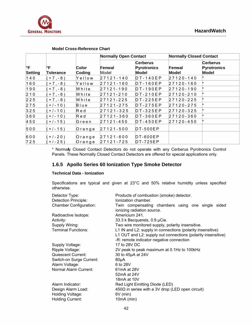
Model Cross-Reference Chart
Normally Open Contact Normally Closed Contact
°F Setting
°F Tolerance
Color Coding
Fenwal Model
Cerberus Pyrotronics Model
Fenwal Model
Cerberus Pyrotronics Model
1 4 0 ( + 7 , - 8 ) Y e l l o w 2 7 1 2 1 - 1 4 0 D T - 1 4 0 E P 2 7 1 2 0 - 1 4 0 * 1 6 0 ( + 7 , - 8 ) Y e l l o w 2 7 1 2 1 - 1 6 0 D T - 1 6 0 E P 2 7 1 2 0 - 1 6 0 * 1 9 0 ( + 7 , - 8 ) W h i t e 2 7 1 2 1 - 1 9 0 D T - 1 9 0 E P 2 7 1 2 0 - 1 9 0 * 2 1 0 ( + 7 , - 8 ) W h i t e 2 7 1 2 1 - 2 1 0 D T - 2 1 0 E P 2 7 1 2 0 - 2 1 0 * 2 2 5 ( + 7 , - 8 ) W h i t e 2 7 1 2 1 - 2 2 5 D T - 2 2 5 E P 2 7 1 2 0 - 2 2 5 * 2 7 5 ( + / - 1 0 ) B l u e 2 7 1 2 1 - 2 7 5 D T - 2 7 5 E P 2 7 1 2 0 - 2 7 5 * 3 2 5 ( + / - 1 0 ) R e d 2 7 1 2 1 - 3 2 5 D T - 3 2 5 E P 2 7 1 2 0 - 3 2 5 * 3 6 0 ( + / - 1 0 ) R e d 2 7 1 2 1 - 3 6 0 D T - 3 6 0 E P 2 7 1 2 0 - 3 6 0 * 4 5 0 ( + / - 1 5 ) G r e e n 2 7 1 2 1 - 4 5 0 D T - 4 5 0 E P 2 7 1 2 0 - 4 5 0 *
5 0 0 ( + / - 1 5 ) O r a n g e 2 7 1 2 1 - 5 0 0 D T - 5 0 0 E P
6 0 0 7 2 5
( + / - 2 0 ) ( + / - 2 5 )
O r a n g e O r a n g e
2 7 1 2 1 - 6 0 0 2 7 1 2 1 - 7 2 5
D T - 6 0 0 E P D T - 7 2 5 E P
* Normally Closed Contact Detectors do not operate with any Cerberus Pyrotronics Control Panels. These Normally Closed Contact Detectors are offered for special applications only.
1.6.5 Apollo Series 60 Ionization Type Smoke Detector Technical Data - Ionization
Specifications are typical and given at 23°C and 50% relative humidity unless specified otherwise.
Detector Type: Products of combustion (smoke) detector. Detection Principle: Ionization chamber. Chamber Configuration: Twin compensating chambers using one single sided
ionizing radiation source. Radioactive Isotope: Americium 241. Activity: 33.3 k Becquerels, 0.9 µCie. Supply Wiring: Two wire monitored supply, polarity insensitive. Terminal Functions: L1 IN and L2: supply in connections (polarity insensitive)
L1 OUT and L2: supply out connections (polarity insensitive) -R: remote indicator negative connection
Supply Voltage: 17 to 28V DC Ripple Voltage: 2V peak to peak maximum at 0.1Hz to 100kHz Quiescent Current: 30 to 45µA at 24V Switch-on Surge Current: 80µA Alarm Voltage: 6 to 28V Normal Alarm Current: 61mA at 28V
52mA at 24V 18mA at 10V
Alarm Indicator: Red Light Emitting Diode (LED) Design Alarm Load: 450Ω in series with a 3V drop (LED open circuit) Holding Voltage: 6V (min) Holding Current: 10mA (min)
HazardWatch
43
Minimum Voltage Required to Illuminate Indicator:
12V
Alarm Reset Voltage: 1V Alarm Reset Time: 1 second Remote Output Characteristics: 900Ω in series with a 3V drop at 24V with 500Ω line
impedance gives: 1mA at 9V 4.5mA at 5V 8.0mA at 1V
Calibration: Factory set to ∆V of 1.3V Sensitivity: Nominal threshold Y value of 0.7 to EN54 Part 7 1984; (BS
5445 Part 7 1984) Temperature Range: Maximum continuous operating temperature 60°C
Minimum continuous operating temperature 0°C Minimum operating temperature (no condensation or icing) -20°C
Temperature Compensation: Automatic compensation by dual chambers to comply with EN 54 Part 7 1984; (BS 5445 Part 7 1984) across the operating temperature range
Humidity: 0% to 95% relative humidity Atmospheric Pressure: Automatic compensation by dual chambers to maintain
sensitivity up to a height of 2000m Wind Speed: 2 m/s maximum (constant)
10 m/s maximum (transient) Vibration: To EN 54 Part 7 1984 (BS 5445 Part 7 1984) Impact: To EN 54 Part 7 1984 (BS 5445 Part 7 1984) Shock: To EN 54 Part 7 1984 (BS 5445 Part 7 1984) Static: IEC 801-2 (BS 6667 Part 2 1985) Severity Level 3. Tested to
12,000V positive and negative to the case and supply terminals from a 250pF capacitor
Radiated Emissions: BS 6527 Class B Radiated Susceptibility: IEC 801 Part 3 Class 3 (10V/m). Tested to 90V/m from
27MHz to 1GHz. IP Rating: 43 Dimensions: Detector: 100mm x 42mm (diameter x height)
Detector in Base: 100mm x 50mm (diameter x height) Weights: Detector: 102 grams.
Detector in Base: 153 grams. Materials: Detector housing: White polycarbonate V-O rated to
UL 94 Terminals: Stainless steel
HazardWatch
44
1.6.6 Apollo Series 60 Photoelectric Type Smoke Detector Technical Data – Optical
Specifications are typical and given at 23°C and 50% relative humidity unless specified.
Detector Type: Products of combustion (smoke) detector Detection Principle: Photoelectric detection of light scattered in a forward
direction by smoke particles Chamber Configuration: Horizontal optical bench housing an infrared emitter
and sensor arranged radially to detect forward scattered light
Sensor: Silicon PIN photo-diode Emitter: GaAs Infrared light emitting diode Sampling Frequency: Once every 10 seconds Confirmation Frequene: Once every 2 seconds Number of Consecutive Sensed Alarm Signals Needed to Trigger Detector Alarm:
3
Supply Wiring: Two wire monitored supply, polarity insensitive Terminal Functions: L1 IN and L2: supply in connections (polarity
insensitive) L1 OUT and L2; supply out connections (polarity insensitive) –R; remote indicator negative connection
Supply Voltage: 17 to 28V DC Ripple Voltage: 2V peak to peak maximum at 0.1Hz to 100kHz Quiescent Current: 30 to 45µA at 24V Switch-on Surge Current: 90µA at 24V Alarm Voltage: 6 to 28V Normal Alarm Current: 61mA at 28V
52mA at 24V 18mA at 10V
Alarm Indicator: Red Light Emitting Diode (LED) emitting red light Design Alarm Load: 450Ω in series with a 3V drop (LED open circuit) Holding Voltage: 6V (min) Holding Current: 10mA (min) Minimum Voltage Required to Light Alarm Indicator:
12V
Alarm Reset Voltage: 1V Alarm Reset Time: 1 second Remote Output Characteristics: 900Ω in series with a 3V drop at 24V with 500Ω line
impedance gives: 1mA at 9V 4.5mA at 5V 8.0mA at 1V
Sensitivity: Nominal threshold of 3.0% light grey smoke obscuration per meter to EN 54 Part 7 1984; (BS 5445 Part 7 1984)
Temperature Range: -20°C to +60°C Temperature Compensation: Negative temperature coefficient thermistor Humidity: 0% to 95% relative humidity (no condensation)
HazardWatch
45
Wind Speed: Insensitive to wind Atmospheric Pressure: Insensitive to atmospheric pressure Vibration: To EN 54 Part 7 1984 (BS 5445 Part 7 1984) Impact: To EN 54 Part 7 1984 (BS 5445 Part 7 1984) Shock: To EN 54 Part 7 1984 (BS 5445 Part 7 1984) Static: IEC 801-2 (BS 6667 Part 2 1985)
Severity Level 3. Tested to 12,000V positive and negative to the case and supply terminals from a 250pF capacitor
Radiated Emissions: BS 6527 Class B Radiated Susceptibility: IEC 801 Part 3 Class 3 (10V/m).
Tested to 90V/m from 27MHz to 1GHz IP Rating: 43 Dimensions: Detector: 100mm x 42mm (diameter x height)
Detector in Base: 100mm x 50mm (diameter x height) Weights: Detector: 99 grams
Detector in Base: 150 grams Materials: Detector housing: White polycarbonate V-O rated to
UL 94 Terminals: Stainless steel
HazardWatch
46
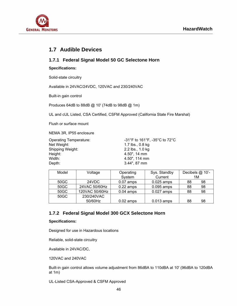
1.7 Audible Devices
1.7.1 Federal Signal Model 50 GC Selectone Horn Specifications:
Solid-state circuitry
Available in 24VAC/24VDC, 120VAC and 230/240VAC
Built-in gain control
Produces 64dB to 88dB @ 10' (74dB to 98dB @ 1m)
UL and cUL Listed, CSA Certified, CSFM Approved (California State Fire Marshal)
Flush or surface mount
NEMA 3R, IP55 enclosure
Operating Temperature: -31°F to 161°F, -35°C to 72°C Net Weight: 1.7 lbs., 0.8 kg Shipping Weight: 2.2 lbs., 1.0 kg Height: 4.50", 14 mm Width: 4.50", 114 mm Depth: 3.44", 87 mm
Model Voltage Operating
System Sys. Standby
Current Decibels @ 10’-
1M 50GC 24VDC 0.07 amps 0.025 amps 88 98 50GC 24VAC 50/60Hz 0.22 amps 0.095 amps 88 98 50GC 120VAC 50/60Hz 0.04 amps 0.027 amps 88 98 50GC 230/240VAC
50/60Hz 0.02 amps 0.013 amps 88 98
1.7.2 Federal Signal Model 300 GCX Selectone Horn Specifications:
Designed for use in Hazardous locations
Reliable, solid-state circuitry
Available in 24VAC/DC,
120VAC and 240VAC
Built-in gain control allows volume adjustment from 86dBA to 110dBA at 10' (96dBA to 120dBA at 1m)
UL-Listed CSA-Approved & CSFM Approved
HazardWatch
47
NEMA Type 3R enclosure; constructed to IP55
Operating Temperature: -31°F to 161° F, -35°C to 72° C Net Weight: 5.2 lbs., 2.4 kg Shipping Weight: 6.7 lbs., 3 kg Height: 12.25", 311 mm Width: 8.00", 203 mm Depth: 8.25", 210 mm
Federal Signal’s SelecTone® Model 300GCX provides audible signals for warning in areas where hazardous materials are stored. The unit has a built-in volume control and a choice of many separate tones that can be heard clearly despite the many ambient noises in a plant.
This unit can be used as a single audible device or as part of a SelecTone system activated by automatic detection devices or a push-button command control.
The SelecTone® model 300GCX is offered in 24VAC/DC, 120VAC or 240VAC voltages. Its sturdy construction consists of a die-cast aluminum amplifier housing and a spun aluminum speaker projector, which are both coated with a gray enamel finish. A conformal coating protects the unit’s PC board and components. The internal gain control allows tone output to be adjusted for 86dBA to a maximum of 110dBA at 10 feet (96dBA to 120dBA at 1m).
The SelecTone model 300GCX can be used as a stand-alone, single signal audible warning device or as part of a plant-wide communication and paging system.
Model 300GCX is recommended for use in Division 2 environments where flammable dusts, liquids, and gases are confined in closed containers,but present potential dangers in the form of accidental ruptures or spillages. This unit is UL(Underwriters Laboratories) listed and CSA (Canadian Standards Association) approved for Class I, Division 2, Groups A, B, C and D; Class II, Division 2, Groups F & G hazardous locations.
Like the 300GC, Federal Signal’s model 300GCX allows for volume to be adjusted to overcome ambient noise levels. Model 300GCX is approved for use in Division 2 environments. Typical applications include emergency warning, start and dismissal, general alarm, evacuation and paging.
Model Voltage Operating System
Sys. Standby Current
Decibels @ 10’-1M
300GCX 24VDC 0.55 amps 0.06 amps 110 120 300GCX 24VAC 50/60Hz 1.25 amps 0.13 amps 110 120 300GCX 120VAC 50/60Hz 0.27 amps 0.03 amps 110 120
300GCX 2240VAC 50/60Hz 0.14 amps 0.02 amps 110 120
1.7.3 Federal Signal Model 300X & 302X Selectone Horn Specifications:
Explosion proof environments
Available in 24VAC/DC, 120VAC and 240VAC
HazardWatch
48
Built-in gain control allows volume adjustment
On the 300X: from 80dB to 104dB at 10' (90dB to 114dB at 1m);
On the 302X: from 90dB to 114dB at 10'; 100dB to 124dB at 1m
UL-Listed, CSA- & CSFM Approved
NEMA Type 3R enclosure; rated for IP44
Specifications for 300X: Net Weight: 18 lbs., 8.2 kg Shipping Weight: 19 lbs., 8.6 kg Height: 14.75", 375 mm Width: 8.88", 225 mm Depth: 14.75", 375 mm
Model Voltage Operating System
Sys. Standby Current
Decibels @ 10’-1M
300X 24VDC 0.50 amps 0.06 amps 104 114 300X 24VAC 50/60Hz 1.30 amps 0.13 amps 104 114 300X 120VAC 50/60Hz 0.27 amps 0.03 amps 104 114 300X 2240VAC 50/60Hz 0.13 amps 0.02 amps 104 114 302X 24VDC 1.10 amps 0.13 amps 114 124 302X 24VAC 50/60Hz 1.10 amps 0.03 amps 114 124
1.7.4 Federal Signal Model 41-X Selectone Horn Specifications:
Designed for use in explosion proof atmospheres
Resonating and vibrating horns
Featuring corrosion-resistant cast aluminum housings
Decibel ratings range from 100-107dB @ 10' (110-117dB @ 1m)
Meets NEMA 4X specifications; constructed to IP44
These Federal Signal explosion proof horns are constructed for safety in hazardous environments. They have heavy-duty die cast aluminum housings which are tapped for 3/4” conduit.
Models 31X and 41X
Federal Signal models 31X and 41X are corrosion-resistant vibrating horns with stainless steel diaphragms. Model 41X is available in 24VDC while model 31X is available in 120VAC, and features an internal volume control.
HazardWatch
49
Both models are UL listed (Underwriters Laboratories) for Class I, Division 1, Groups C & D; Class I, Division 2, Groups C & D; Class II, Division 1, Groups E, F, and G and Class III. Both are CSA (Canadian Standards Association) approved.
Models 55X and 56X
Federal Signal models 55X and 56X are resonating electric horns which produce sound by means of a diaphragm which resonates a column of air. Their gray enamel finished housings are tapped for 3/4” conduit. Model 55X is available in 120VAC, while model 56X is available in 125VDC.
Model 55X is UL listed for Class I, Division 1, Groups C & D; Class I, Division 2, Groups C & D; Class II, Division 1, Groups E, F & G and
Class III. Both model 55X and 56X are CSA (Canadian Standards Association) approved.
These vibrating and resonating explosion-proof horns are designed for locations such as refineries, laboratories, mines or grain elevators where the danger of explosion or fire exists.
Operating Temperature: -31°F to 150°F, -35°C to 66°C Net Weight: (31X) (41X) (55X) (56X)
7.5 lbs., 3.4 kg 9.0 lbs., 4.1 kg 10.5 lbs., 4.8 kg 10.5 lbs., 4.8 kg
Shipping Weight: (31X) (41X) (55X) (56X)
8.1 lbs., 3.7 kg 10.3 lbs., 4.7 kg 12.5 lbs., 5.7 kg 15.5 lbs., 7kg
Model Voltage Amperage Decibels @ 10’-1M
31X 120VAC 50/60Hz 0.20 100 110 31X 240VAC 50/60Hz 0.10 100 110 41X 24VDC 1.20 100 110 55X 120VAC 60Hz 0.65 105 115 56X 125VDC 0.50 107 117
1.7.5 MEDC XB3 Horn Zone 1, Zone 2 and non-Ex use.
EExde IIC T5.
ATEX approved, Ex II 2GD.
Optional Exe terminal chamber.
BASEEFA certified.
UL Listed for USA and Canada
HazardWatch
50
−Hazardous locations:
Class I, Div 2, Groups A-D.
Class I, Zones 1 & 2, AExd IIC T4.
−Ordinary locations: Audible-Signal Device.
GOST ‘R’ & ‘K’ certified.
Chinese (CQST) certified.
Australian (SAA) certified.
IP66 and IP67.
*Certified temperature –55°C to +70°C.
All GRP corrosion free flamepaths.
Up to 118dBA output.
Integral volume control.
27 tones, user selectable.
Tones comply with UK00A/PFEER guidelines.
Any two tones may be switched via the external voltage supply.
Tones may be programmed to customer specification.
d.c. version accepts any voltage between12V d.c. and 48V d.c.
End of line resistor option.
Sounder/Beacon Combination Unit available.
*Depending on version.
Certifications: CENELEC EN50014, 18, 19. BASEEFA Cert. No. BAS00ATEX2097X, EExd IIC. BASEEFA Cert. No. BAS00ATEX2098X, EExde IIC. Zones 1 and 2. UL Listed for USA and Canada – Hazardous locations: Class I Div 2, Groups A-D. Class I Zones 1 & 2, AExd IIC T4. Listing No: E203310. – Ordinary locations: Audible-Signal Device. Listing No. S8116. Refer to UL data sheet at rear of catalogue for
HazardWatch
51
complete information. GOST ‘R’ Certification: 1Exd IIC T4 & 1Exde IIC T4. GOST ‘K’ Certification: 1Exd IIC T4. Chinese (CQST) Certification: Exd IIC T4.
Material: Body & horn in anti-static, UV stable, glass reinforced polyester. Swivel bracket & captive cover screws in stainless steel.
Finish: Body and horn, natural black or epoxy paint coated to client’s colour requirements.
Sound Output: Long Flare: 115dB(A) ± 3dB(A) (tone dependent). Short Flare: 108dB(A) ± 3dB(A) (tone dependent).
Volume Control
Nominal Output (dBA) Input Current (mA)
93 50 105 100 108 150 111 200 112 250 114 300 115 350
*Output measured with 24V input voltage. Tone set to 970Hz continuous.
Weight: 6.0kg approx. dependent on model (+0.5kg for EExe).
Ingress Protection: IP66 and IP67 Fire Retardancy: GRP is fire retardant to ISO 1210 Voltage: Up to 48V d.c. Up to 254V a.c
Certified Temperature
EExd EExde
UL
GOST ‘R’&‘K’
GOST ‘R’ Exde
Chinese Exd
DB3 & DB3P
-20°C to +70°C
-20°C to +45°C
-55°C to +70°C
-20°C to +50°C
-20°C to +40°C
-20C to +55°C
DB3L & DB3LP
-55°C to +55°C
-55°C to +70°C
n/a
-55°C to +55°C
-55°C to +55°C
n/a
Current Consumption
V I 12V d.c. 760mA 24V d.c. 380mA 48V d.c. 190mA 110V a.c 135mA 120V a.c. 124mA 220V a.c. 68mA 240V a.c. 62mA 254V a.c. 59mA
Terminals: 4 x 2.5mm2 (a.c.), 6 x 2.5mm2 (d.c.). Earth Continuity: Included on EExde version. Mounting: Stainless steel bracket with ratchet facility.
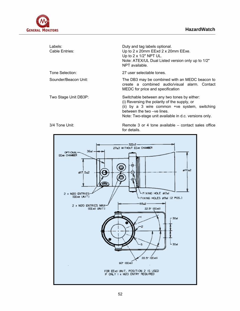
HazardWatch
52
Labels: Duty and tag labels optional. Cable Entries: Up to 2 x 20mm EExd 2 x 20mm EExe.
Up to 2 x 1/2" NPT UL. Note: ATEX/UL Dual Listed version only up to 1/2" NPT available.
Tone Selection: 27 user selectable tones.
Sounder/Beacon Unit: The DB3 may be combined with an MEDC beacon to create a combined audio/visual alarm. Contact MEDC for price and specification
Two Stage Unit DB3P: Switchable between any two tones by either: (i) Reversing the polarity of the supply, or (ii) by a 3 wire common +ve system, switching between the two –ve lines. Note: Two-stage unit available in d.c. versions only.
3/4 Tone Unit: Remote 3 or 4 tone available – contact sales office for details.

HazardWatch
53
HazardWatch
54
1.7.6 Notifier Spectralert Horn Specifications:
Horn shall be a System Sensor SpectrAlert Model capable of operating at 12 and 24 volts. Horn shall be listed to UL 464 for fire protective signaling systems. The horn shall have two-tone options, two audibility options (at 24 volts) and the option to switch between a temporal 3 pattern and a non-temporal continuous pattern. All horn models shall operate on a coded power supply.
Walk Test SpectrAlert horn/strobe and horn only work on “walk tests” with time durations of 4 seconds or greater.
Input Terminals 12 to 18 AWG
Dimensions
Strobe and horn/strobe with universal plate:
5" x 5 5/8" x 215/16"
Strobe and horn/strobe with small footprint plate:
33/8" x 5 5/8" x 25/16"
Horn with universal mounting plate: 5" x 5 5/8" x 15/16" Horn without mounting plate: 215/16" x 5 5/16" x 15/16" Weight, horn only: 7.2 oz. Weight, strobe and horn/strobe: 8.8 oz. Mounting: 4" x 4" x 1 1/2" or 2" x 4" x 1 7/8" standard boxes
Environment
Indoor Operating Temperature: 32°F to 120°F (0°C to 49°C) Weatherproof (horn and horn/strobes) Operating Temperature: 32°F to 150°F (0°C to 66°C) (Outdoor strobe only): -40°F to 158°F (-40°C to 70°C) ULC Canadian Models: -40°C to 66°C
Electrical
Voltages 12 or 24VDC and FWR unfiltered Operating voltage range* 12V: 10.5-17V; 24V: 20-30V Operating voltage range* 12V, 11-17V; 24V, 20-30V (with Sync•Circuit
module, MDL)
* These products should be operated within their rated voltage range; UL does, however, test functional integrity to -20% and +10% of manufacturer's stated ranges.
1.7.7 Notifier Spectralert Horn
1.7.8 Crouse Hinds ESR Fire Alarm Bell Specifications:
Application:
ESR bell signals are used: for call signals, alarms, or in various other signaling applications in specific hazardous atmospheres such as in chemical plants, oil and gas refineries, bulk loading stations, paint and varnish manufacturing plants, grain processing industries and
HazardWatch
55
grain elevators, as well as in certain metal, coal, combustible fiber processing or handling areas in conduit systems, and mounted on a vertical flat surface with the striker at the bottom
Features:
• The conduit hub contains an integral bushing.
• The body cover assembly permits the location of a hub at the top, bottom or either side (the striker must be located at the bottom for proper operation).
• There are no external seals required except when used in Group B hazardous areas. • The ac signal does not have arcing contacts.
• The dc signal is provided with a GUAC junction box, with factory sealed wire leads in the interconnecting nipple and hub.
• Binding screw terminals are provided in ac signals for supply conductors.
• A vibrating or single stroke striker mechanism is furnished with 6 or 10 inch diameter gongs.
• Standard Materials:
• Body - Feraloy iron alloy
• Cover - copper-free aluminum
• Junction box - body - Feraloy iron alloy - cover - copper-free aluminum
• Gong - steel
• Standard Finishes:
• Feraloy iron alloy - electrogalvanized and aluminum acrylic paint
• Aluminum - natural
• Steel - gray matte
• Size Ranges: Hub - one 3/4" size
Operating Current in Amperes at the Nominal Voltage For Bell Signals
Amperes All Vibrating All Single Stroke NOM 25 to 60 50 to 60 Volts Hertz AC DC Hertz ACDC 12 1.67 1.69 1.75 2.40 24 .53 .63 .62 1.53 48 .44 .65 .41 .95 115 .189 135 .189 .42 230 .092 .086
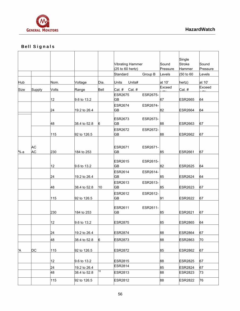
HazardWatch
56
Bel l S i g n a l s
Vibrating Hammer (25 to 60 hertz)
Sound Pressure
Single Stroke Hammer
Sound Pressure
Standard Group B Levels (50 to 60 Levels
Hub Nom. Voltage Dia. Units Units# at 10' hertz) at 10'
Size Supply Volts Range Bell Cat. # Cat. # Exceed (dB)
Cat. # Exceed (dB)
12 9.6 to 13.2 ESR2675 ESR2675-GB 67 ESR2665 64
24 19.2 to 26.4 ESR2674 ESR2674-GB 82 ESR2664 64
48 38.4 to 52.8 6 ESR2673 ESR2673-GB 88 ESR2663 67
115 92 to 126.5 ESR2672 ESR2672-GB 88 ESR2662 67
'% a AC AC 230 184 to 253
ESR2671 ESR2671-GB 85 ESR2661 67
12 9.6 to 13.2 ESR2615 ESR2615-GB 82 ESR2625 64
24 19.2 to 26.4 ESR2614 ESR2614-GB 85 ESR2624 64
48 38.4 to 52.8 10 ESR2613 ESR2613-GB 85 ESR2623 67
115 92 to 126.5 ESR2612 ESR2612-GB 91 ESR2622 67
230 184 to 253 ESR2611 ESR2611-GB 85 ESR2621 67
12 9.6 to 13.2 ESR2875 85 ESR2865 64
24 19.2 to 26.4 ESR2874 88 ESR2864 67
48 38.4 to 52.8 6 ESR2873 88 ESR2863 70
'A DC 115 92 to 126.5 ESR2872 85 ESR2862 67
12 9.6 to 13.2 ESR2815 88 ESR2825 67
24 19.2 to 26.4 ESR2814 85 ESR2824 67 48 38.4 to 52.8 10 ESR2813 88 ESR2823 73
115 92 to 126.5 ESR2812 88 ESR2822 76
HazardWatch
57
1.7.9 Pyrotronics MBDC-6 Fire Alarm Bell Series MBDC Motor Bells & Strobe Bells
• UL Listed for Fire Protective Service.
• High Sound output with low current draw.
• Low frequency aluminum shells for better audibility through walls, doors and other structures.
• Both 6” and 10” shell sizes in 24 VDC models.
• Integral RFI suppression to minimize induced noise on the alarm lines.
• Mounting options for surface, semi-flush, outdoor and concealed conduit installation.
• Built-in trimplate makes semi-flush mounting simpler and less expensive.
• Screw terminals permit fast in-out field wiring of 12-22 AWG wire.
• Polarized for DC supervision of alarm lines.
• Operate on filtered or unfiltered DC over a wide voltage range.
• Strobe bells for combined audible and visual signaling have single input to save wiring time for 2-wire tandem operation of bell and strobe.
Architects Specifications
The alarm signals shall be Pyrotronics Series MBDC vibrating Motor Bells or approved equal. They shall be UL Listed for Fire Protective Service. Shells shall be aluminum in 6” or 10” diameter. Sound output at 10 feet shall be 92 dBA. The bells shall incorporate a carbon brush motor and suppression to minimize RFI. They shall include a built-in trimplate for semi-flush mounting to standard 4” backboxes, or surface mounting to Pyrotronics indoor IBH-2 backbox or outdoor WBK-3 backbox.
Strobe bell models shall include an integral flashing strobe light with white polycarbonate lens and red “Fire” lettering. The strobe shall be factory wired to operate in unison with the bell and shall produce 8000 peak candlepower at approximately one flash per second. The strobe bells shall semi-flush mount to standard 4” square backboxes, or surface mount using Pyrotronics SB backbox. All bell and strobe bell models shall be polarized for line supervision and shall have screw terminals for in-out field wiring of 12-22 AWG wire. Operating voltage shall range from 19.2-28.8 VDC. Finish on all models shall be textured red enamel.
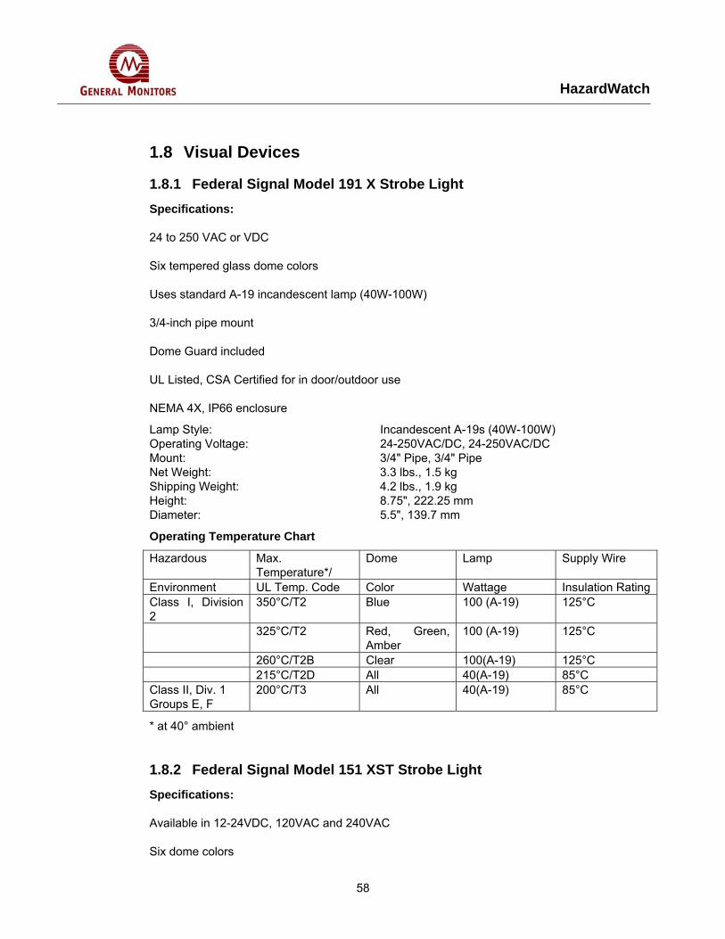
HazardWatch
58
1.8 Visual Devices
1.8.1 Federal Signal Model 191 X Strobe Light Specifications:
24 to 250 VAC or VDC
Six tempered glass dome colors
Uses standard A-19 incandescent lamp (40W-100W)
3/4-inch pipe mount
Dome Guard included
UL Listed, CSA Certified for in door/outdoor use
NEMA 4X, IP66 enclosure
Lamp Style: Incandescent A-19s (40W-100W) Operating Voltage: 24-250VAC/DC, 24-250VAC/DC Mount: 3/4" Pipe, 3/4" Pipe Net Weight: 3.3 lbs., 1.5 kg Shipping Weight: 4.2 lbs., 1.9 kg Height: 8.75", 222.25 mm Diameter: 5.5", 139.7 mm
Operating Temperature Chart
Hazardous Max. Temperature*/
Dome Lamp Supply Wire
Environment UL Temp. Code Color Wattage Insulation RatingClass I, Division 2
350°C/T2 Blue 100 (A-19) 125°C
325°C/T2 Red, Green, Amber
100 (A-19) 125°C
260°C/T2B Clear 100(A-19) 125°C 215°C/T2D All 40(A-19) 85°C Class II, Div. 1 Groups E, F
200°C/T3 All 40(A-19) 85°C
* at 40° ambient
1.8.2 Federal Signal Model 151 XST Strobe Light Specifications:
Available in 12-24VDC, 120VAC and 240VAC
Six dome colors
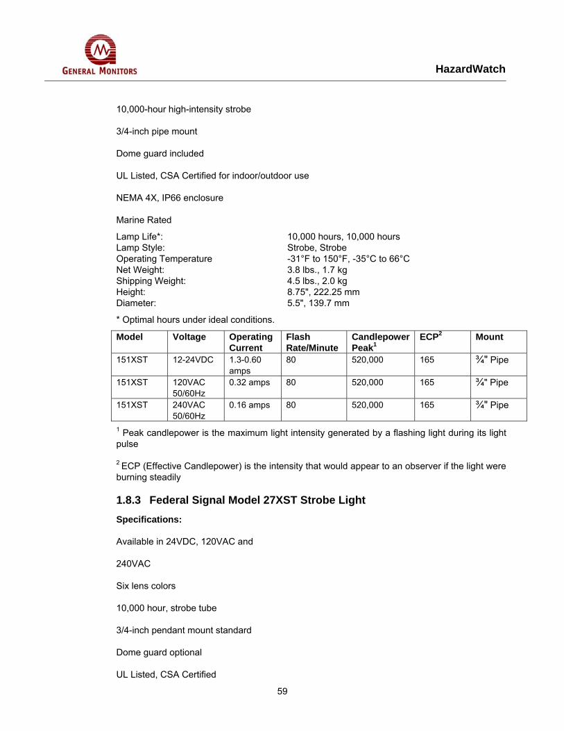
HazardWatch
59
10,000-hour high-intensity strobe
3/4-inch pipe mount
Dome guard included
UL Listed, CSA Certified for indoor/outdoor use
NEMA 4X, IP66 enclosure
Marine Rated
Lamp Life*: 10,000 hours, 10,000 hours Lamp Style: Strobe, Strobe Operating Temperature -31°F to 150°F, -35°C to 66°C Net Weight: 3.8 lbs., 1.7 kg Shipping Weight: 4.5 lbs., 2.0 kg Height: 8.75", 222.25 mm Diameter: 5.5", 139.7 mm
* Optimal hours under ideal conditions.
Model Voltage Operating Current
Flash Rate/Minute
Candlepower Peak1
ECP2 Mount
151XST 12-24VDC 1.3-0.60 amps
80 520,000 165 ¾" Pipe
151XST 120VAC 50/60Hz
0.32 amps 80 520,000 165 ¾" Pipe
151XST 240VAC 50/60Hz
0.16 amps 80 520,000 165 ¾" Pipe
1 Peak candlepower is the maximum light intensity generated by a flashing light during its light pulse
2 ECP (Effective Candlepower) is the intensity that would appear to an observer if the light were burning steadily
1.8.3 Federal Signal Model 27XST Strobe Light Specifications:
Available in 24VDC, 120VAC and
240VAC
Six lens colors
10,000 hour, strobe tube
3/4-inch pendant mount standard
Dome guard optional
UL Listed, CSA Certified
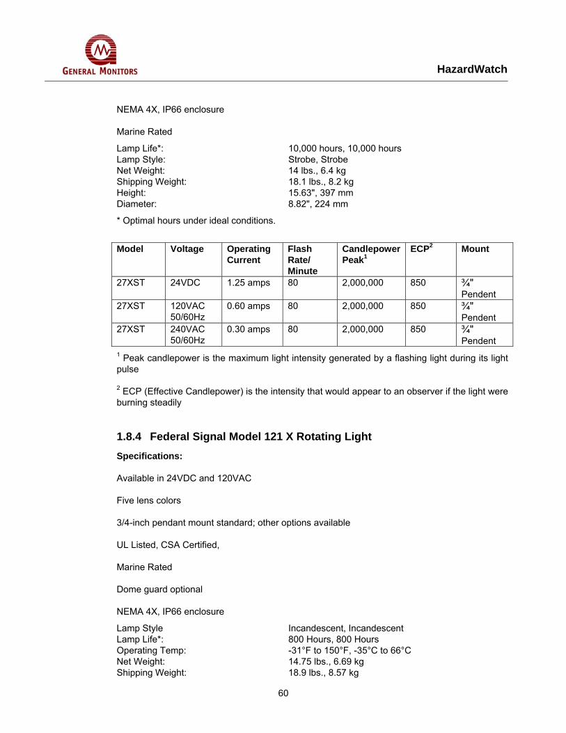
HazardWatch
60
NEMA 4X, IP66 enclosure
Marine Rated
Lamp Life*: 10,000 hours, 10,000 hours Lamp Style: Strobe, Strobe Net Weight: 14 lbs., 6.4 kg Shipping Weight: 18.1 lbs., 8.2 kg Height: 15.63", 397 mm Diameter: 8.82", 224 mm
* Optimal hours under ideal conditions.
Model Voltage Operating
Current Flash Rate/ Minute
Candlepower Peak1
ECP2 Mount
27XST 24VDC 1.25 amps 80 2,000,000 850 ¾" Pendent
27XST 120VAC 50/60Hz
0.60 amps 80 2,000,000 850 ¾" Pendent
27XST 240VAC 50/60Hz
0.30 amps 80 2,000,000 850 ¾" Pendent
1 Peak candlepower is the maximum light intensity generated by a flashing light during its light pulse
2 ECP (Effective Candlepower) is the intensity that would appear to an observer if the light were burning steadily
1.8.4 Federal Signal Model 121 X Rotating Light Specifications:
Available in 24VDC and 120VAC
Five lens colors
3/4-inch pendant mount standard; other options available
UL Listed, CSA Certified,
Marine Rated
Dome guard optional
NEMA 4X, IP66 enclosure
Lamp Style Incandescent, Incandescent Lamp Life*: 800 Hours, 800 Hours Operating Temp: -31°F to 150°F, -35°C to 66°C Net Weight: 14.75 lbs., 6.69 kg Shipping Weight: 18.9 lbs., 8.57 kg
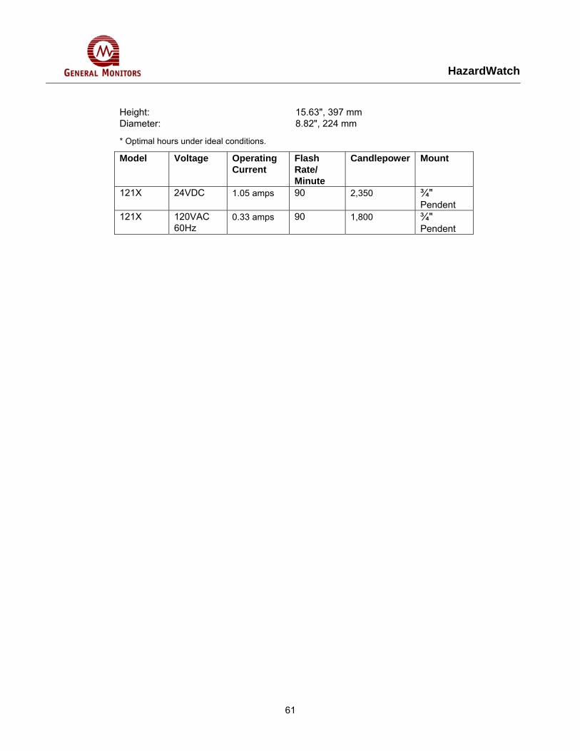
HazardWatch
61
Height: 15.63", 397 mm Diameter: 8.82", 224 mm
* Optimal hours under ideal conditions.
Model Voltage Operating Current
Flash Rate/ Minute
Candlepower Mount
121X 24VDC 1.05 amps 90 2,350 ¾" Pendent
121X 120VAC 60Hz
0.33 amps 90 1,800 ¾" Pendent
HazardWatch
62
1.8.5 MEDC XB-3 Strobe Light Specifications:
Zone 1 and Zone 2 use.
Class 1, Div. 1
EExd, EExde IICT4/T6.
CENELEC approved.
BASEEFA Certified.
CSA Certified.
UL Listed (SM87 HXBA only).
GOST Certified.
IP66 and IP67.
Stainless steel or marine grade alloy.
Xenon or LED versions.
Optional EExe terminal chamber.
Various lens colours.
Optional lens guard.
Telephone or relay initiated.
Certification BASEEFA EExdIIC T6 (HXB & LED). EExde IIC T6 (XB3 & LED3). Cert. No. Ex88B1232 (HXB & LED). Ex 92C 1389 (XB3 & LED3). CENELEC EN50014 and EN50018 and EN50019. CSA Certification to C22.2 Nos. 0, 0.4, 0.5, 9, 30-M1986, 94-M91, 137-M1981. Class 1. Div 1. Group D. Enclosure 3/4. Cert. No. 96406. (SM87 HXB only). UL Listed for Class 1, Div. 1, Groups C + D (SM87 HXB only). GOST Certification: Contact MEDC for specification
Material: HXBS and LEDS – Grade 316 ANC4B Stainless Steel. HXBA & LEDA – LM25 TF Marine Grade Alloy.
Lens: Toughened Glass Finish: Epoxy paint finish as standard or to customer's
specification
NOTE: Terminal Chamber available only in Stainless Steel. UL version is available only in marine grade alloy. CSA version available only in stainless steel
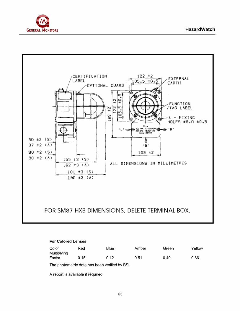
HazardWatch
63
For Colored Lenses
Color Red Blue Amber Green Yellow Multiplying Factor 0.15 0.12 0.51 0.49 0.86
The photometric data has been verified by BSI.
A report is available if required.
HazardWatch
64
LED Light Output Color Total LED Output (Candela) Steady or Flashing (Customer selectable)
Red Amber Green Blue
192 64 17 64
LED/Lens Color: Red, Blue, Green, Amber, Yellow (not LED) or Clear (not LED).
Weight: HXBS & LEDS – 3.8kg each (approx). XB3 & LED3 – 4.5kg (approx).
HXBA & LEDA: 2kg. each (approx.). BASEEFA HXB = –55°C to +55°C. Operating XB3 = –20°C to +40°C. Temperature: LED = –20°C to +40°C. LED3: –20°C to +40°C.
Versions are available certified up to +55°C maximum with a T4 rating.
UL Operating
Temperature: HXB = –25°C to +40°C. Ingress Protection: IP66 & IP67. Terminals: XB3&LED3–6offsuitableforupto6mm2 cable. (With
telephone initiate 8 x 2.5mm2). HXB: 4 off suitable for up to 2.5mm2 cable. LED: 6 off suitable for up to 2.5mm2 cable. Termination: Models HXB & LED use a single Exd chamber.
Models XB3 & LED3incorporate an Exe chamber for termination.
Telephone initiation or relay interface:
Initiation by telephone ringing tone or low voltage control signals.
Labels: Duty & Tag Labels optional. Entries: Up to 4 x 20mm / 25mm ISO or 1/2" / 3/4" NPT.
(HXB, LED). 3 x 20mm or 25mm ISO (XB3, LED3)
HazardWatch
65
1.8.6 MEDC XB-11 Strobe Light Specifications:
Zone 1 and Zone 2 use.
Exd IIB T4, T5 & T6.
ATEX approved, Ex II 2GD. BASEEFA certified.
UL Listed for USA and Canada
Hazardous locations:
Class I, Div 2, Groups C & D.
Class I, Zones 1 & 2, AExd IIB T4/T5.
Ordinary locations: Visual-Signal Device.
Australian (SAA) certified.
Chinese (CQST) certified. I
P66 and IP67.
Certified temperature –55°C to +70°C.
Corrosion resistant GRP.
Optional stainless steel backstrap.
Various lens colours.
Optional lens guard.
Optional telephone initiation.
2 x M20 cable entries or 2 x 1/2" NPT*.
Earth continuity option (model dependent).
Filament version (20W) available†.
Fluorescent version (10W) available†.
Beacon/Sounder Combination Unit available.
*Model dependent. †See FL11, FB11, FL12, FB12 data sheet.
HazardWatch
66
Certification:
CENELEC EN50014 and EN50018. Cert. No. BAS99 ATEX 2195X.
EExd IIB 135°C (-55 t.amb +70°C) T4., 100°C (-55 t.amb +55°C) T5., 85°C (-55 t.amb +40°C) T6.
UL Listed for USA and Canada to: –Hazardous locations: Class I, Div 2 Groups C & D. Class I, Zones 1 & 2 AExd IIB T4/T5.
UL Listing No: E187894. –Ordinary locations: Visual-Signal Device.
UL listing No. S8128.
Refer to UL Datasheet at rear of catalogue for complete information.
Chinese (CSQT) Certification: Exd IIB T5/T6.
Material: Body: Glass reinforced polyester (GRP) Lens: Glass Cover Screws + Backstrap: Stainless steel 316 Finish: Natural black or painted to customer specification
DC AC50/60 Hz Voltage 24 110 240 XB11 Tube Energy (Joules) 5 5 5 Peak Current Consumption (mA) 320 100 60 Effective Intensity (Cd) 29 29 29 Peak Intensity (Cd) 22213 22213 22213 Power Consumption (Watts) 8 11 18 NOTE: The Cd figures are for a clear lens @ 1Hz flash rate
For Colored Lenses
Color Red Blue Amber Green Yellow Multiplying Factor
0.15 0.12 0.51 0.49 0.86
The photometric data has been verified by BSI.
A report is available if required.
Weight: 2.5Kg. Certified Temperature: EExd −55°C to +70°C (T4).
−55°C to +55°C (T5). −55°C to +40°C (T6). UL −55°C to +70°C (hazardous locations).
HazardWatch
67
−55°C to +55°C (ordinary locations). Ingress Protection: IP66 & IP67 Fire Retardancy: GRP is fire retardant to ISO 1210 Earth Continuity: Optional for metal glands provided via a brass plate.
(Not available for UL version). Terminals: 6 x 2.5mm2 Telephone initiation: Initiation by telephone ringing tone Labels: Duty/Tag Label optional Entries: 2 x 20mm ISO EExd.
2 x ½" NPT UL. Beacon/Sounder Unit: The beacon may be combined with an MEDC sounder
to create a visual/audible alarm. Contact MEDC for price and specification.
NOTE: ATEX/UL Dual Listed unit has up to 2 x ½" NPT entries only.
1.8.7 Notifier Spectralert Strobe Specification:
Walk test: SpectrAlert® horn/strobe and horn only work on “walk tests” with time durations of 4 seconds or greater.
Input terminals: 12 to 18 AWG (3.25 mm² to 0.51 mm²) Dimensions, strobe and horn/strobe with universal plate:
5" (12.7 cm) wide x 5.625" (14.288 cm) high x 2.938" (7.461 cm) deep; with small footprint plate: 3.375" (8.573 cm) wide x 5.625" (14.288 cm) high x 2.938" (7.461 cm) deep.
Weight, strobe and horn/strobe: 8.8 oz. (250 g) Mounting: Standard boxes 4" x 4" x 1.5" deep (10.16 x 10.16 x
3.81 cm) or 2" x 4" x 1.875" deep (5.08 x 10.16 x 4.763 cm).
Operating temperature Indoor: 32°F to 120°F (0°C to 49°C) Outdoor: Weatherproof Horn/Strobe 32°F to 150°F (0°C to 66°C) Strobe -40°F to 158°F (-40°C to 70°C), ULC Canadian strobe model -40°C to 66°C.
Maximum humidity: 95% as tested per UL 464. Voltages: 12 or 24 VDC and FWR unfiltered. Operating voltage range*: 12V 8 – 17.5 V 24V: 16 – 33 V. With Sync-Circuit™
module MDL*: 12V: 9 – 17.5 V. 24V: 17 – 33 V. U.S. Patent Numbers: 5,593,569. 5,914,665. 6,049,446.
*Note for Strobe: Do not exceed; 1) 16-33 or 8-17.5 voltage range limit; 2) maximum number of 70 strobe lights when connecting the MDL Sync Module with a maximum line impedance of 4 ohms per loop and; 3) maximum line impedance as required by the fire alarm control manufacturer.
HazardWatch
68
Engineering Specifications
General — SpectrAlert® horns, strobes and horn/strobes shall be capable of mounting to a standard 4" x 4" x 1.5" (10.16 x 10.16 x 3.81 cm) backbox or a single-gang 2" x 4" x 1.875" (5.08 x 10.16 x 4.763 cm) backbox using the universal mounting plate included with each SpectrAlert® product. Also, SpectrAlert® products, when used in conjunction with the accessory Sync•Circuit™ Module, shall be powered from a non-coded power supply and shall operate on 12 or 24 volts. 12-volt rated devices shall have an operating voltage range of 9 – 17.5 volts. 24-volt rated devices shall have an operating voltage range of 17-33 volts. SpectrAlert® products shall have an indoor operating temperature range of 32°F to 120°F (0°C to 49°C) and operate from a regulated DC or full-wave rectified, unfiltered power supply.
Strobe — Strobe shall be a System Sensor SpectrAlert® model _________ Listed to UL 1971 and be approved for fire protective service. The strobe shall be wired as a primary signaling notification appliance and comply with the Americans with Disabilities Act requirements for visible signaling appliances, flashing at 1 Hz over the strobe’s entire operating voltage range. The strobe light shall consist of a xenon flash tube and associated lens/reflector system.
Horn/Strobe Combination — Horn/strobe shall be a System Sensor SpectrAlert® model _________ Listed to UL 1971 and UL 464 and shall be approved for fire protective service. Horn/strobe shall be wired as a primary signaling notification appliance and comply with the Americans with Disabilities Act requirements for visible signaling appliances, flashing at 1 Hz over the strobe’s entire operating voltage range. The strobe light shall consist of a xenon flash tube and associated lens/reflector system. The horn shall have two tone options, two audibility options (at 24 volts) and the option to switch between a temporal 3 pattern and a non-temporal continuous pattern. Strobes shall be powered independently of the sounder with the removal of factory-installed jumper wires. The horn on horn/strobe models shall operate on a coded or non-coded power supply (the strobe must be powered continuously).
Synchronization Module — Module shall be a System Sensor Sync•Circuit™ model _________ Listed to UL 464 and shall be approved for fire protective service. The module shall synchronize SpectrAlert® strobes at 1 Hz and horns at temporal 3. Also, the module shall silence the horns on horn/strobe models, while operating the strobes, over a single pair of wires. The module shall be capable of mounting to a 4.688" (11.906 cm) square x 2.125" (5.398 cm) deep backbox and shall control two Style Y (Class B) or one Style Z (Class A) circuit. Module shall be capable of multiple zone synchronization by daisy-chaining multiple modules together and resynchronizing each other along the chain. The module shall NOT operate on a coded power supply.

69
HazardWatch