HAZARDOUS LOCATION REMOTE I/O - rstahl.com · HAZARDOUS LOCATION REMOTE I/O INNOVATIVE EXPLOSION...
81
HAZARDOUS LOCATION REMOTE I/O
Transcript of HAZARDOUS LOCATION REMOTE I/O - rstahl.com · HAZARDOUS LOCATION REMOTE I/O INNOVATIVE EXPLOSION...

H A Z A R D O U S L O C A T I O N R E M O T E I / O

Protection against explosions represents safety technology at its highest level.Based upon the many years of experience in the manufacture of explosion protected lift equipment, a special division was formed in 1955 to manufactureexplosion protected switchgear and control equipment - R.Stahl SchaltgerateGmbH.
Through a series of pathfinding developments and innovative designs, the enterprise quickly gained worldwide leadership in the specialized field of explosion protection. Today R.Stahl is represented in many countries and acrossall continents by over 20 subsidiaries.
Established in 1979, R.Stahl, Inc. was tasked with introducing our explosion protection technology to the North American market. Through a combination ofsuperior training and service, R.Stahl, Inc. has expanded to include over 40 representatives throughout the Americas.
Our highly trained sales engineers are ready to find solutions to your hazardouslocation applications. Our expertise and products are used by industry leadersall over the world. Let us provide you with the same competitive edge.

HAZARDOUS LOCATION REMOTE I/O
INNOVATIVE EXPLOSION PROTECTION, by R.STAHL 1 - 800 - 782 - 4357 i
• Easy engineering by using a PowerBus and BusRail
• Fieldbus communication: Modbus RTU, Profibus DP, HARTover Profibus DP V1
• All I/O modules are hot swappable
• Optional ServiceBus for configuration, setting parameters, faultdiagnostics and HART communication
• Redundancy available for the fieldbus, the CPU and the power supply
• Modular remote I/O system for mounting on 35 x 15mm DIN Rail
• Installation in Div. 1 & 2, Zone 1 & 2 and in a nonhazardous location
• Inputs and outputs - intrinsically safe for Div. 1 & 2, Zone 1 & 2
• HART input and output modules for transmitters and positioners
• Digital output relay modules available for non I.S. outputs in ahazardous location
• Field enclosures available in many versions to fit specific engineering requirements
With IS 1, Stahl are introducing their second generation remote I/O system for hazardous locations.
IS 1 is very easy to use: A CPU & Power Module (CPM) and, according to requirements, several input and output modules are snapped on tothe BusRail (in 35 x 15mm DIN rail). The unique power supply concept, PowerBus, developed especially for use in hazardous locations, makessystem engineering as simple as it is with conventional industrial I/O systems.
IS 1 is particularly flexible: It can be used for large and small quantities, with the option to install field stations in Division 1 or 2, Zone 1 or 2.Equally feasible is its installation in control rooms. An intrinsically safe fieldbus, using copper or fiber optic technology, connects the field stationsin Division 1, Zone 1, with the control system.
IS 1 is very economical: Modules with 4, 8 or 16 inputs, lowers the price per signal. The optional ServiceBus, in connection with the Stahl“I.S. Wizard” PC software, cuts down the time for commissioning and troubleshooting.
Nonhazardous, Division 1 and 2, Zone 1 and 2 Locations.
Introduction
General Overview

HAZARDOUS LOCATION REMOTE I/O
INNOVATIVE EXPLOSION PROTECTION, by R.STAHL 1 - 800 - 782 - 4357ii
IS 1 and any Environment
Hot - Desert LocationsCold - Arctic CircleWet - Offshore PlatformsVibration and Shock - Ship and Turbine InstallationsCorrosive - Chemical and Petrochemical Industries
Introduction
EurothermE-Suite
Emerson Process ManagementDelta VProvox
FoxboroMicro I/A
GE Fanuc90 Series
HoneywellC200 Experion
MitsubishiMelsec A
IS 1 and any Industry
PharmaceuticalChemicalAmmunition FacilitiesDistilleries / BreweriesWaste Water TreatmentPetrochemicalPower GenerationOil and GasFPSOOffshore Drilling and ProductionAerospacePulp and PaperAutomotiveMiningMarineTank Farms
IS 1 and any Company
BayerPharmaciaAbott LaboratoriesFirmenichSmith and NephewGlaxoSmithKlineCroda ChemicalsBASFRocheTexacoShellAlliant Tech SystemsIrish Distillers3MCiba Speciality ChemicalsNovartis
Remote I/O System - IS 1, The reference list just keeps growing
ABBFreelance 2000SattlineSymphony
AEG SchneiderA 250
Allen BradleySLC 5PLC 5Control LogixSoftlogix 5800
AlstomICS 800
IS 1 and any Automation System
ModiconQuantum
Omron
SiemensS7S5AS 488PCS 7
Vosper Thornycroft ControlsVTC PLC
YokogawaCentum CS 3000

HAZARDOUS LOCATION REMOTE I/O
INNOVATIVE EXPLOSION PROTECTION, by R.STAHL 1 - 800 - 782 - 4357 1
Contents
Introduction iGeneral Overview i
System Description 2Assembly and Configuration of a Field Station 2Internal Bus 2Fieldbus 3System Topology 4ServiceBus 4ServiceBus and “I.S. Wizard” Software 5ServiceBus and HART 6HART over Profibus DP 6Redundancy 6Hot Swap 7Input and Output Modules for Analog Signals 8Input and Output Modules for Digital Signals 8Input and Output Modules for Non I.S. Digital Signals 9CPU & Power Modules 9CPM Bases 10BusRail Components 10
System Components 12Division 1, Zone 1 CPM Types 9440/12 and 9440/22 12Division 2, Zone 2 CPM Type 9440/15 16Analog Input Module Type 9460 20Analog Input Module HART Type 9461/12-08-11 22Analog Input Module HART Type 9461/12-08-21 24Temperature Input Module Resistance Type 9480 26Temperature Input Module mVoltage Type 9481 30Analog Output Module Type 9465 34Analog Output Module HART Type 9466 36Digital Input Module Type 9470 38Digital Output Module Type 9475 42Digital Output Module Type 9477/15 48Digital Output Module Type 9477/12 50Nonhazardous Digital Input Module Type 9471 54BusRail Components Type 9494 58
System Accessories 60General Accessories 60Enclosures 63
Common System Data 64Common System Data 64Dimensions 66Engineering Examples 70
Certifications and Approvals 72IS 1 Components 72
Remote I/O System - IS 1

HAZARDOUS LOCATION REMOTE I/O
INNOVATIVE EXPLOSION PROTECTION, by R.STAHL 1 - 800 - 782 - 43572
System Description
The IS 1 system is a modern, cost-effective and flexible remote I/O system suitable for installation in hazardous locations with inputs and outputs that are intrinsically safe for Division 1 and 2, Zone 1 and 2. There are also three digital output relay modules available for non I.S. outputs in a hazardous location that can be placed on the same BusRail as the I.S. I/O modules.
The uniform system concept permits installation in Division 1 and 2, Zone 1 and 2 and in the nonhazardous location. The inputs and outputs areoptimised for the sensors and actuators used in process technology.
The integration of different fieldbuses permits digital communication with mostautomation systems (PLC, DCS, PC).
IS 1 consists of the following components:
• BusRail - for the internal communication bus and the power supply to the I/O modules
• CPU & Power Module - for the system communication and power supply
• I/O modules - for the inputs and outputs of the process signals
A wide variety of enclosures are available to meet the specific configuration andenvironmental requirements associated with an IS1 system and the processapplication.
The I/O modules have 4, 6, 8 or 16 channels and can be plugged into any available position on the BusRail after the CPM. Up to 16 I/Omodules can be configured for an installation in a Division 2, Zone 2 or nonhazardous location. Up to 8 I/O modules can be configured for aninstallation in a Division 1, Zone 1 location. The BusRail can be partitioned mechanically into several rails and connected by means of a pre-manufactured cable.
The internal bus enables the data exchange between the CPM and the I/Omodules. It is a component of the BusRail. The I/O modules are addressed onthe internal bus by means of the slot on the BusRail in relation to the CPM, soan address setting is not necessary.
The internal bus is designed to be fundamentally redundant in the BusRail andin all modules, so that, even in the event of a fault, the communication betweenmodules is guaranteed.
Internal Bus
Assembly and Configuration of an IS 1 Field Station

HAZARDOUS LOCATION REMOTE I/O
INNOVATIVE EXPLOSION PROTECTION, by R.STAHL 1 - 800 - 782 - 4357 3
The fieldbus is the connection between the CPM and the automation system (PLC, DCS, PC). The input and output data between the fieldstations and the automation system are exchanged over the fieldbus.
Fieldbuses which can be connected:
• Profibus DP, up to 1.5MBit/s (PTO Approved)
• HART over Profibus DP V1, up to 1.5MBit/s (PTO Approved)
• Modbus RTU, up to 38.4kBit/s
• Other fieldbuses in preparation
Depending on the functionality of the fieldbus, the following functions are supported:
• Configuration of the IS 1 field station or read back the configuration
• Load the modules with parameters
• Read input data and force output data
• Transfer the alarms and diagnostic data of a field station
• Transfer HART commands (Profibus DP V1)
The fieldbus is intrinsically safe for field stations installed in a Division 1, Zone 1 location. A fieldbus isolating repeater guarantees the intrinsicsafety of the fieldbus segment. Several fieldbus isolating repeaters are allowed to be connected as repeaters to a fieldbus. Several designs areavailable, depending upon the system requirements and components used.
Depending on the system components several field stations can be connected to an intrinsically safe RS 485 segment at the maximum speed of1.5MBit/s. A maximum of 32 stations (master or slaves, i.e. PLC’s, isolating repeaters, field stations) can be connected to an RS 485 fieldbussegment which is not intrinsically safe. When more than 32 stations are required repeaters can be used to add extra segments. The number offield stations that can be addressed depends on the fieldbus protocol (e.g. up to 124 with Profibus DP).
Fieldbus
System Description

HAZARDOUS LOCATION REMOTE I/O
INNOVATIVE EXPLOSION PROTECTION, by R.STAHL 1 - 800 - 782 - 43574
System Description
System Topology
ServiceBus
In addition to the fieldbus connection, the CPM provides an interface for theServiceBus. The ServiceBus can be connected to a PC and enables the useof the R.Stahl “I.S. Wizard” PC software or a HART management software package, so that the following can be carried out on the connected field stations:
• Input and output simulation
• Configuration
• Setting of parameters
• Commissioning and fault diagnostics
• HART commands
Several field stations can be connected on the ServiceBus.
HAZARDOUS LOCATION REMOTE I/O
INNOVATIVE EXPLOSION PROTECTION, by R.STAHL 1 - 800 - 782 - 4357 5
System Description
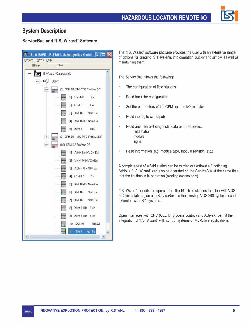
The “I.S. Wizard” software package provides the user with an extensive rangeof options for bringing IS 1 systems into operation quickly and simply, as well asmaintaining them.
The ServiceBus allows the following:
• The configuration of field stations
• Read back the configuration
• Set the parameters of the CPM and the I/O modules
• Read inputs, force outputs
• Read and interpret diagnostic data on three levels: field stationmodulesignal
• Read information (e.g. module type, module revision, etc.)
A complete test of a field station can be carried out without a functioning fieldbus. “I.S. Wizard” can also be operated on the ServiceBus at the same timethat the fieldbus is in operation (reading access only).
“I.S. Wizard” permits the operation of the IS 1 field stations together with VOS200 field stations, on one ServiceBus, so that existing VOS 200 systems can beextended with IS 1 systems.
Open interfaces with OPC (OLE for process control) and ActiveX, permit theintegration of “I.S. Wizard” with control systems or MS-Office applications.
ServiceBus and “I.S. Wizard” Software

HAZARDOUS LOCATION REMOTE I/O
INNOVATIVE EXPLOSION PROTECTION, by R.STAHL 1 - 800 - 782 - 43576
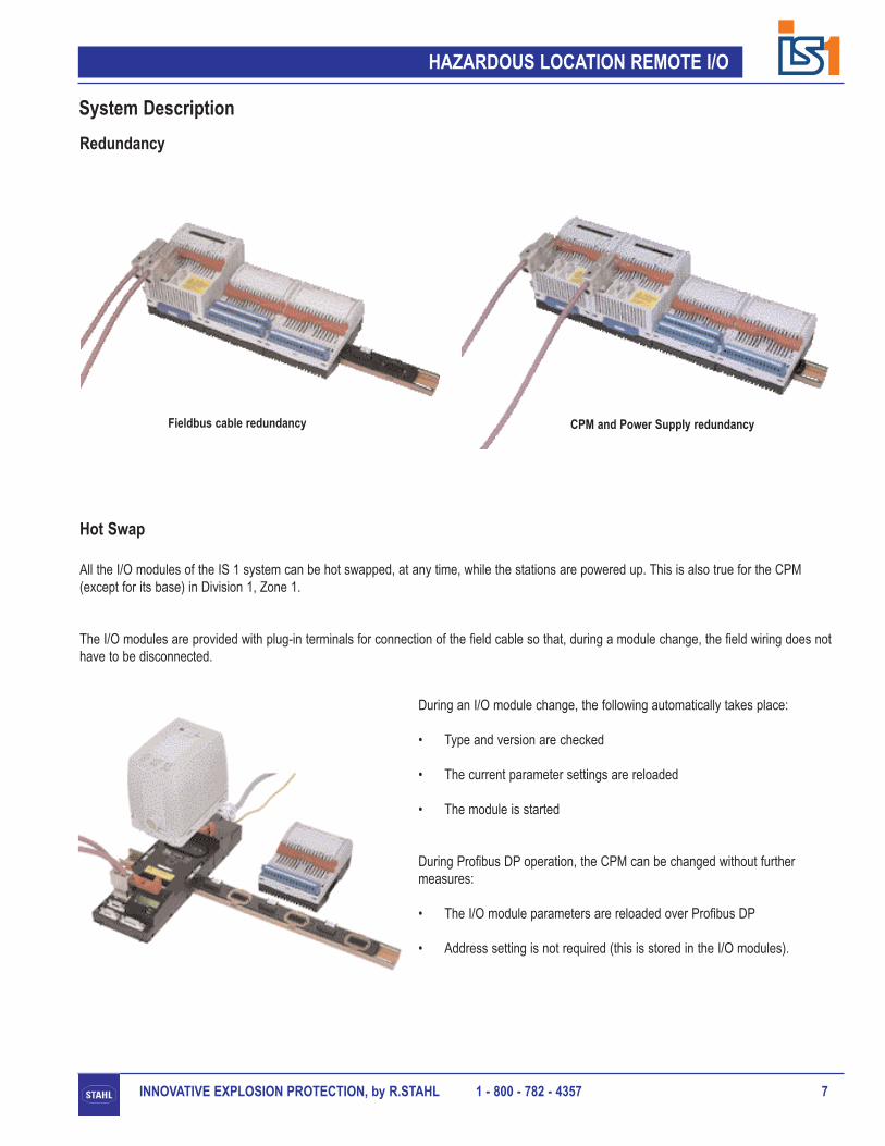
The high availability of the IS 1 system required by industrial processing applications is guaranteed using a proven redundancy concept.Different optional redundancy stages permit customization by the user to meet their requirements:
• Fieldbus cable redundancy (Profibus DP only)
• CPU redundancy
• Power supply redundancy
The internal bus of an IS 1 field station is always redundant.
Redundancy
ServiceBus and HART
The transfer of the HART commands is achieved either
• over the ServiceBus or
• over the fieldbus (e.g. with Profibus DP V1)
Software packages that allow the overall database for all HART field devices tobe managed from a central position, can be operated directly on theServiceBus. Software packages which are compatible with the ServiceBus are:
• AMS from Emerson Process Management
• PDM from Siemens
• Fieldcare from Endress and Hauser
• Cornerstone from ASTEC
• PRM from Yokogawa
System Description
The ServiceBus can also be used to transfer HART commands to, and from, HART field devices. In this way, there is the option of setting HARTfield equipment parameters at a central location, interrogating the diagnostic data, and managing the corresponding data base.
Individual HART modules are available for the connection of HART transmitters and positioners. The process value is transferred with the 0 / 4 ... 20mA signal. The IS 1 field station appears transparent, for the exchange of HART commands, between an engineering station and theHART field devices.
The HART information is also available over the fieldbus with Profibus DP V1. The methodology and accessability of the HART informationwithin the automation system is dependent on the automation system used. To access the HART information within the FDT (Field Device Tool)frame application a communication DTM (Device Type Manager) is available from R.Stahl - “DTM HART Gateway DP IS 1”. The CPM, 9440/..-..-..-HART, must also be used.
For more information on HART with IS 1, please contact R.Stahl.
HART over Profibus DP
HAZARDOUS LOCATION REMOTE I/O
INNOVATIVE EXPLOSION PROTECTION, by R.STAHL 1 - 800 - 782 - 4357 7
During an I/O module change, the following automatically takes place:
• Type and version are checked
• The current parameter settings are reloaded
• The module is started
During Profibus DP operation, the CPM can be changed without furthermeasures:
• The I/O module parameters are reloaded over Profibus DP
• Address setting is not required (this is stored in the I/O modules).
Hot Swap
System Description
All the I/O modules of the IS 1 system can be hot swapped, at any time, while the stations are powered up. This is also true for the CPM(except for its base) in Division 1, Zone 1.
The I/O modules are provided with plug-in terminals for connection of the field cable so that, during a module change, the field wiring does nothave to be disconnected.
Redundancy
Fieldbus cable redundancy CPM and Power Supply redundancy

HAZARDOUS LOCATION REMOTE I/O
INNOVATIVE EXPLOSION PROTECTION, by R.STAHL 1 - 800 - 782 - 43578
Type Description Channels Explosion protection for Typical application
9460/12-08-11 Analog Input Module 8, 4 Div. 1 & 2, Zone 1 & 2 • 2, 3 and 4 wire transmitters, active 0 / 4 - 20 mA0 / 4 ... 20 mA
9461/12-08-11 Analog Input Module 8 Div. 1 & 2, Zone 1 & 2 • 2 wire transmitters with HART communication0 / 4 ... 20 mA HART
9461/12-08-21 Analog Input Module 8 Div. 1 & 2, Zone 1 & 2 • 2 and 4 wire transmitters with HART communication0 / 4 ... 20 mA HART
9480/12-08-11 Temperature Input Module 8 Div. 1 & 2, Zone 1 & 2 • Resistance thermometer, (RTD, Pt 100, Pt 1000 etc)Resistance • Potentiometer
9481/12-08-11 Temperature Input Module 8 Div 1 & 2, Zone 1 & 2 • Thermocouples, mV signalsmVoltage
9465/12-08-11 Analog Output Module 8 Div. 1 & 2, Zone 1 & 2 • Positioner, I/P converter, Indicator0 / 4 ... 20mA
9466/12-08-11 Analog Output Module 8 Div. 1 & 2, Zone 1 & 2 • Positioner with HART communication0 / 4 ... 20mA HART
System Description
Input and Output Modules for Analog Signals
Type Description Channels Explosion protection for Typical application
9470/22-16-11 Digital Input Module 16 Div. 1 & 2, Zone 1 & 2 • NAMUR proximity switch, Contact, Opto coupler• Frequency, Counter
9475/12-04-11 Digital Output Module 4 Div. 1 & 2, Zone 1 & 2 • Solenoid, LED indicator, Horn
9475/22-04-11 Digital Output Module 4 Div. 1 & 2, Zone 1 & 2 • Solenoid, LED indicator, Horn, with Plant ‘STOP’
9475/12-04-21 Digital Output Module 4 Div. 1 & 2, Zone 1 & 2 • Solenoid, LED indicator, Horn
9475/12-04-31 Digital Output Module 4 Div. 1 & 2, Zone 1 & 2 • Solenoid, LED indicator, Horn
9475/12-08-41 Digital Output Module 8 Div. 1 & 2, Zone 1 & 2 • Solenoid, LED indicator, Horn
9475/12-08-51 Digital Output Module 8 Div. 1 & 2, Zone 1 & 2 • Solenoid, LED indicator, Horn
9475/22-08-51 Digital Output Module 8 Div. 1 & 2, Zone 1 & 2 • Solenoid, LED indicator, Horn, with Plant ‘STOP’
9475/12-08-61 Digital Output Module 8 Div. 1 & 2, Zone 1 & 2 • Solenoid, LED indicator, Horn
9475/22-08-61 Digital Output Module 8 Div. 1 & 2, Zone 1 & 2 • Solenoid, LED indicator, Horn, with Plant ‘STOP’
Input and Output Modules for Digital Signals
HAZARDOUS LOCATION REMOTE I/O
INNOVATIVE EXPLOSION PROTECTION, by R.STAHL 1 - 800 - 782 - 4357 9
Type Description Explosion protection for Typical application
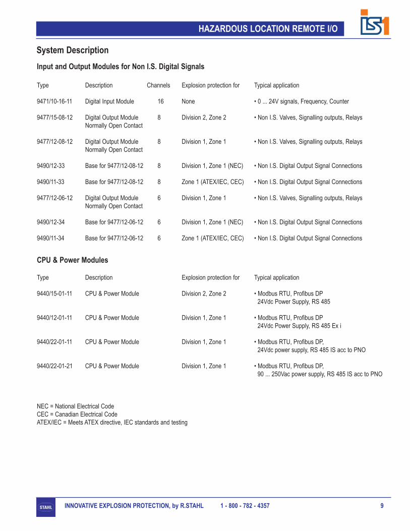
9440/15-01-11 CPU & Power Module Division 2, Zone 2 • Modbus RTU, Profibus DP24Vdc Power Supply, RS 485
9440/12-01-11 CPU & Power Module Division 1, Zone 1 • Modbus RTU, Profibus DP24Vdc Power Supply, RS 485 Ex i
9440/22-01-11 CPU & Power Module Division 1, Zone 1 • Modbus RTU, Profibus DP, 24Vdc power supply, RS 485 IS acc to PNO
9440/22-01-21 CPU & Power Module Division 1, Zone 1 • Modbus RTU, Profibus DP, 90 ... 250Vac power supply, RS 485 IS acc to PNO
NEC = National Electrical CodeCEC = Canadian Electrical CodeATEX/IEC = Meets ATEX directive, IEC standards and testing
System Description
Type Description Channels Explosion protection for Typical application
9471/10-16-11 Digital Input Module 16 None • 0 ... 24V signals, Frequency, Counter
9477/15-08-12 Digital Output Module 8 Division 2, Zone 2 • Non I.S. Valves, Signalling outputs, RelaysNormally Open Contact
9477/12-08-12 Digital Output Module 8 Division 1, Zone 1 • Non I.S. Valves, Signalling outputs, RelaysNormally Open Contact
9490/12-33 Base for 9477/12-08-12 8 Division 1, Zone 1 (NEC) • Non I.S. Digital Output Signal Connections
9490/11-33 Base for 9477/12-08-12 8 Zone 1 (ATEX/IEC, CEC) • Non I.S. Digital Output Signal Connections
9477/12-06-12 Digital Output Module 6 Division 1, Zone 1 • Non I.S. Valves, Signalling outputs, RelaysNormally Open Contact
9490/12-34 Base for 9477/12-06-12 6 Division 1, Zone 1 (NEC) • Non I.S. Digital Output Signal Connections
9490/11-34 Base for 9477/12-06-12 6 Zone 1 (ATEX/IEC, CEC) • Non I.S. Digital Output Signal Connections
Input and Output Modules for Non I.S. Digital Signals
CPU & Power Modules

HAZARDOUS LOCATION REMOTE I/O
INNOVATIVE EXPLOSION PROTECTION, by R.STAHL 1 - 800 - 782 - 435710
Type Description Explosion protection for Typical application
9494/S1-M4 BusRail 4 modules Div. 1 & 2, Zone 1 & 2 • BusRail for 4 modules
9494/S1-B2 BusRail 2 modules, begin Div. 1 & 2, Zone 1 & 2 • BusRail for 2 modules, begin
9494/S1-E2 BusRail 2 modules, end Div. 1 & 2, Zone 1 & 2 • BusRail for 2 modules, end
9494/A1-BO BusRail End Cap, begin Div. 1 & 2, Zone 1 & 2 • Cover for the open end of the BusRail, begin
9494/A1-EO BusRail End Cap, end Div. 1 & 2, Zone 1 & 2 • Cover for the open end of the BusRail, end
9494/A2-BO BusRail End Cap, begin Sub-D Div. 1 & 2, Zone 1 & 2 • Cover for the open end of the BusRail, beginwith a Sub-D connector for the BusRail extension
9494/A2-EO BusRail End Cap, end Sub-D Div. 1 & 2, Zone 1 & 2 • Cover for the open end of the BusRail, endwith a Sub-D connector for the BusRail extension
9491/Z0-VB Connection cable - 43.3”, 1.1m Div. 1 & 2, Zone 1 & 2 • Connection cable between two BusRail segments
9491/Z0-VB 0.47 Connection cable - 18.5”, 0.47m Div. 1 & 2, Zone 1 & 2 • Connection cable between two BusRail segments
BusRail Components
System Components
Type Description Explosion protection for Typical application
9490/12-11 Base for CPM - 9440/12 Division 1, Zone 1 (NEC) • Connection of Power Supply and CommunicationLinks, LCD Display and Push Buttons
9490/11-11 Base for CPM - 9440/12 Zone 1 (ATEX/IEC, CEC) • Connection of Power Supply and CommunicationLinks, LCD Display and Push Buttons
9490/12-12-dc Base for CPM - 9440/22-..-11 Division 1, Zone 1 (NEC) • Connection of Power Supply and CommunicationLinks, LCD Display and Push Buttons
9490/12-12-ac Base for CPM - 9440/22-..-21 Division 1, Zone 1 (NEC) • Connection of Power Supply and CommunicationLinks, LCD Display and Push Buttons
9490/11-12 Base for CPM - 9440/22 Zone 1 (ATEX/IEC, CEC) • Connection of Power Supply and CommunicationLinks, LCD Display and Push Buttons
CPM Bases

HAZARDOUS LOCATION REMOTE I/O
INNOVATIVE EXPLOSION PROTECTION, by R.STAHL 1 - 800 - 782 - 4357 11
HAZARDOUS LOCATION REMOTE I/O
INNOVATIVE EXPLOSION PROTECTION, by R.STAHL 1 - 800 - 782 - 435712
System Components
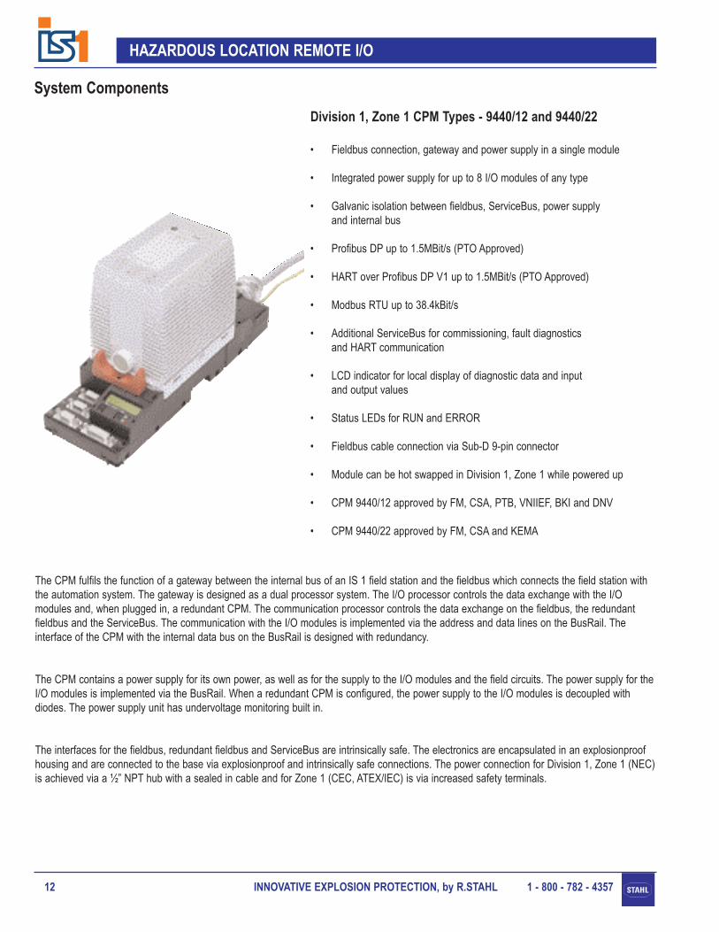
• Fieldbus connection, gateway and power supply in a single module
• Integrated power supply for up to 8 I/O modules of any type
• Galvanic isolation between fieldbus, ServiceBus, power supply and internal bus
• Profibus DP up to 1.5MBit/s (PTO Approved)
• HART over Profibus DP V1 up to 1.5MBit/s (PTO Approved)
• Modbus RTU up to 38.4kBit/s
• Additional ServiceBus for commissioning, fault diagnosticsand HART communication
• LCD indicator for local display of diagnostic data and input and output values
• Status LEDs for RUN and ERROR
• Fieldbus cable connection via Sub-D 9-pin connector
• Module can be hot swapped in Division 1, Zone 1 while powered up
• CPM 9440/12 approved by FM, CSA, PTB, VNIIEF, BKI and DNV
• CPM 9440/22 approved by FM, CSA and KEMA
The CPM fulfils the function of a gateway between the internal bus of an IS 1 field station and the fieldbus which connects the field station withthe automation system. The gateway is designed as a dual processor system. The I/O processor controls the data exchange with the I/O modules and, when plugged in, a redundant CPM. The communication processor controls the data exchange on the fieldbus, the redundantfieldbus and the ServiceBus. The communication with the I/O modules is implemented via the address and data lines on the BusRail. Theinterface of the CPM with the internal data bus on the BusRail is designed with redundancy.
The CPM contains a power supply for its own power, as well as for the supply to the I/O modules and the field circuits. The power supply for theI/O modules is implemented via the BusRail. When a redundant CPM is configured, the power supply to the I/O modules is decoupled withdiodes. The power supply unit has undervoltage monitoring built in.
The interfaces for the fieldbus, redundant fieldbus and ServiceBus are intrinsically safe. The electronics are encapsulated in an explosionproofhousing and are connected to the base via explosionproof and intrinsically safe connections. The power connection for Division 1, Zone 1 (NEC)is achieved via a ½” NPT hub with a sealed in cable and for Zone 1 (CEC, ATEX/IEC) is via increased safety terminals.
Division 1, Zone 1 CPM Types - 9440/12 and 9440/22

INNOVATIVE EXPLOSION PROTECTION, by R.STAHL 1 - 800 - 782 - 4357 13
HAZARDOUS LOCATION REMOTE I/O
System Components
Order Code
RS 485 IS acc. to PTO specification, Power Supply - 24Vdc:CPM for installation in Division 1, Zone 1 - Profibus DP: 9440/22-01-11-DPCPM for installation in Division 1, Zone 1 - Modbus RTU: 9440/22-01-11-RTUCPM for installation in Division 1, Zone 1 - HART over Profibus DP: 9440/22-01-11-HARTBase for CPM - Division 1, Zone 1 (NEC): 9490/12-12-dcBase for CPM - Zone 1 (CEC, ATEX/IEC): 9490/11-12
RS 485 IS acc. to PTO specification, Power Supply - 90 ... 250Vac:CPM for installation in Division 1, Zone 1 - Profibus DP: 9440/22-01-21-DPCPM for installation in Division 1, Zone 1 - Modbus RTU: 9440/22-01-21-RTUCPM for installation in Division 1, Zone 1 - HART over Profibus DP: 9440/22-01-21-HARTBase for CPM - Division 1, Zone 1 (NEC) : 9490/12-12-acBase for CPM - Zone 1 (CEC, ATEX/IEC): 9490/11-12
RS 485 Ex i, Power Supply - 24Vdc:CPM for installation in Division 1, Zone 1 - Profibus DP: 9440/12-01-11-DPCPM for installation in Division 1, Zone 1 - Modbus RTU: 9440/12-01-11-RTUCPM for installation in Division 1, Zone 1 - HART over Profibus DP: 9440/12-01-11-HARTBase for CPM - Division 1, Zone 1 (NEC): 9490/12-11Base for CPM - Zone 1 (CEC, ATEX/IEC): 9490/11-11
Enclosure wall conduit entry assembly: 9491/00-13-70
Fieldbus, Redundant Fieldbus and ServiceBus Interfaces
Interface:9440/12: RS 485 Ex i9440/22: RS 485 IS acc. to PTO specification
Topology: LineMaximum line length: 3,900ft, 1,200m - Copper, 6,500ft, 2,000m - Fiber OpticTransfer speed:
Fieldbus (X1, X2):Profibus DP: 9.6kBit/s ... 1.5MBit/s: max. 40 x 16 Bit word/msModbus RTU: 9.6kBit/s ... 38.4kBit/s: max. 1000 x 16 Bit registers/s
ServiceBus (X3): 9.6kBit/sLine termination:
9440/12: Passive resistor, 120 ohms9440/22: Powered resistor, 200 ohms
Address setting: 0 ... 127
Human Interface
LED indication: Green “RUN” LED, Red “ERR” LEDLCD indication and user push buttons: 2 x 16 characters, 2 push buttonsInput (only if the fieldbus is not in operation): Bus address
Simulate / force digital and analog outputsDisplay (at any time): Bus address, alarms / faults
Information (type, revision etc) for the three levels - field station, module and signal
Input and output values

INNOVATIVE EXPLOSION PROTECTION, by R.STAHL 1 - 800 - 782 - 435714
HAZARDOUS LOCATION REMOTE I/O
System Components
Parameters
Type of storage for the fieldbus address: Non-volatileType of storage for the remaining parameters, (CPM and I/O modules):
Profibus DP: Volatile, (non-volatile in the Profibus Master)Modbus RTU: Non-volatile
Fieldbus: Bus address, fieldbus specific parametersParameters for system configuration: CPM redundancy, slot and type of I/O moduleRetrievable parameters: Manufacturer, type, version, serial number
Fault Diagnostics, Alarms
CPM faults: Hardware error, configuration errorI/O module faults: Internal bus error (primary or redundant), no response
Incorrect module configuration, hardware error
Characteristic Values
Maximum signal delay through the system, without module delay DI / DO AI / AO(from inputs to the fieldbus or from the fieldbus to the outputs)with 8 I/O modules connected: 7ms 10ms
Power Supply for the I/O Modules (provided by the CPM)
Voltage range: 22.5Vdc ... 26.2VdcMaximum current: 2AMaximum number of I/O modules: 8Diode decoupling for redundant supply of I/O modules: YesUndervoltage monitoring: Yes
System Power Supply9440/x2-01-11 9440/22-01-21
Rated voltage: 24Vdc 110 / 230VacVoltage range: 20Vdc ... 35Vdc 90 ...250VacCurrent input at 24V (without I/O modules): 350mA 25mA@230Vac
48mA@110VacPower dissipation (without I/O modules): 8.4W 8.4WPower dissipation per connected I/O module: approx 1W approx 1WReverse polarity protection: Yes n/aBehaviour defined for low voltage: Yes Yes
Power Supply for the 9372/11-21-30: Available only on the Zone 1 (CEC, ATEX/IEC)CPM base type - 9490/11-12
Nominal Voltage: 24VNominal Current: 45mA
Special Engineering and Mounting Instructions
For an installation in Division 1, Zone 1 (NEC) a standard enclosure with rating NEMA 4, 4x, IP66 may be used. The enclosure wall conduitentry assembly must be used.
For an installation in Zone 1 (CEC, ATEX/IEC) an enclosure with protection class Ex e, EEx e must be used.
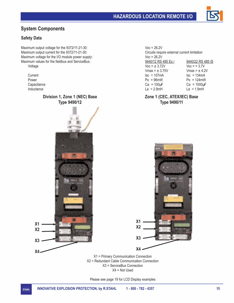
Division 1, Zone 1 (NEC) BaseType 9490/12
Zone 1 (CEC, ATEX/IEC) Base Type 9490/11
X1X2
X3
X4
X1X2
X3
X4
INNOVATIVE EXPLOSION PROTECTION, by R.STAHL 1 - 800 - 782 - 4357 15
HAZARDOUS LOCATION REMOTE I/O
System Components
X1 = Primary Communication ConnectionX2 = Redundant Cable Communication Connection
X3 = ServiceBus ConnectionX4 = Not Used
Please see page 19 for LCD Display examples
Safety Data
Maximum output voltage for the 9372/11-21-30: Voc = 26.2VMaximum output current for the 9372/11-21-30: Circuits require external current limitationMaximum voltage for the I/O module power supply: Voc = 26.2VMaximum values for the fieldbus and ServiceBus: 9440/12 RS 485 Ex i 9440/22 RS 485 IS
Voltage Voc = ± 3.72V Voc = + 3.7VVmax = ± 3.75V Vmax = ± 4.2V
Current Isc = 107mA Isc = 134mAPower Po = 96mW Po = 124mWCapacitance Ca = 100µF Ca = 1000µFInductance La = 2.9mH La = 1.9mH

INNOVATIVE EXPLOSION PROTECTION, by R.STAHL 1 - 800 - 782 - 435716
HAZARDOUS LOCATION REMOTE I/O
System Components
Division 2, Zone 2 CPM Type - 9440/15
• Fieldbus connection, gateway and power supply in a single module
• Integrated power supply for up to 16 I/O modules of any type
• Galvanic isolation between fieldbus, ServiceBus, power supply and internal bus
• Profibus DP up to 1.5MBit/s (PTO Approved)
• HART over Profibus DP V1 up to 1.5MBit/s (PTO Approved)
• Modbus RTU up to 38.4kBit/s
• Additional ServiceBus for commissioning, fault diagnosticsand HART communication
• LCD indicator for local display of diagnostic data and inputand output values
• Status LEDs for RUN and ERROR
• Fieldbus cable connection via Sub-D 9-pin, standard, connectors
• Approved by FM, CSA, PTB, SEV, VNIIEF, BKI, EVPU, FTZU and DNV
The CPM fulfils the function of a gateway between the internal bus of an IS 1 field station and the fieldbus which connects the field station withthe automation system. The gateway is designed as a dual processor system. The I/O processor controls the data exchange with the I/O modules and, when plugged in, a redundant CPM. The communication processor controls the data exchange on the fieldbus, the redundantfieldbus and the ServiceBus. The communication with the I/O modules is implemented via the address and data lines on the BusRail. The interface of the CPM with the internal data bus on the BusRail is designed with redundancy.
The CPM contains a power supply for its own power, as well as for the supply to the I/O modules and the field circuits. The power supply for theI/O modules is implemented via the BusRail. When a redundant CPM is configured, the power supply to the I/O modules is decoupled withdiodes. The power supply unit has undervoltage monitoring built in.
The power supply connection is achieved via a plug-in terminal at the back of the module. The interface connections for the fieldbus andServiceBus are nonincendive.

INNOVATIVE EXPLOSION PROTECTION, by R.STAHL 1 - 800 - 782 - 4357 17
HAZARDOUS LOCATION REMOTE I/O
System Components
Order Code
CPM for installation in Division 2, Zone 2 - Profibus DP: 9440/15-01-11-DPCPM for installation in Division 2, Zone 2 - Modbus RTU: 9440/15-01-11-RTUCPM for installation in Division 2, Zone 2 - HART over Profibus DP: 9440/15-01-11-HART
Fieldbus, Redundant Fieldbus and ServiceBus Interfaces
Interface: RS 485Topology: LineMaximum line length: 3,900ft, 1,200m - Copper
6,500ft, 2,000m - Fiber OpticTransfer speed:
Fieldbus (X1, X2):Profibus DP: 9.6kBit/s ... 1.5MBit/s: max. 40 x 16 Bit words/msModbus RTU: 9.6kBit/s ... 38.4kBit/s: max. 1000 x 16 Bit registers/s
ServiceBus(X3): 9.6kBit/sLine termination: Corresponding to fieldbus standardAddress setting: 0 ... 127
Human Interface
LED indication: Green “RUN” LED, Red “ERR” LEDLCD indication and user push buttons: 2 x 16 characters, 2 push buttonsInput (only if the fieldbus is not in operation): Bus address
Simulate / force digital and analog outputsDisplay (at any time): Bus address, alarms / faults
Information (type, revision etc) for the three levels - field station, module and signal
Input and output values
Parameters
Type of storage for the fieldbus address: Non-volatileType of storage for the remaining parameters, (CPM and I/O modules):
Profibus DP: Volatile, (non-volatile in the Profibus Master)Modbus RTU: Non-volatile
Fieldbus: Bus address, fieldbus specific parametersParameters for system configuration: CPM redundancy, slot and type of I/O moduleRetrievable parameters: Manufacturer, type, version, serial number
Fault Diagnostics, Alarms
CPM faults: Hardware error, configuration errorI/O module faults: Internal bus error (primary or redundant), no response
Incorrect module configuration, hardware error

X1 = Primary Communication ConnectionX2 = Redundant Cable Communication Connection
X3 = ServiceBus ConnectionX4 (25 pin Sub-D Connector) = Not Used
Sub-D Connection Designations
INNOVATIVE EXPLOSION PROTECTION, by R.STAHL 1 - 800 - 782 - 435718
HAZARDOUS LOCATION REMOTE I/O
Characteristic Values
Maximum signal delay through the system, without module delay DI / DO AI / AO(from inputs to the fieldbus or from the fieldbus to the outputs)with 16 I/O modules connected: 7ms 10ms
Power Supply for the I/O Modules (provided by the CPM)
Voltage range: 22.5Vdc ... 26.2VdcMaximum Current: 4AMaximum number of I/O modules: 16Diode decoupling for redundant supply of I/O modules: YesUndervoltage monitoring: Yes
System Power Supply
Rated voltage: 24VdcVoltage range: 20Vdc ... 35VdcCurrent input at 24V (without I/O modules): 350mAPower dissipation (without I/O modules): 8.4WPower dissipation per connected I/O module: approx 1WReverse polarity protection: YesBehaviour defined for low voltage: Yes
Safety Data
Maximum voltage for the I/O module power supply: Voc = 26.2V
System Components

INNOVATIVE EXPLOSION PROTECTION, by R.STAHL 1 - 800 - 782 - 4357 19
HAZARDOUS LOCATION REMOTE I/O
System Components
LCD Display - Diagnostic Information
Which Fieldbus? Is everything OK? What’s in slot 2?
What’s the signal doing? Problem with the signal? Oops - Short Circuit!
Oops - Open Circuit! What happened to the module? Who inserted the wrong module?

INNOVATIVE EXPLOSION PROTECTION, by R.STAHL 1 - 800 - 782 - 435720
HAZARDOUS LOCATION REMOTE I/O
• Up to 8 channels (**see below)
• Module and inputs intrinsically safe for installation in Division 1 and 2, Zone 1 and 2
• 0 ... 20mA and 4 ... 20mA signals
• For 2-wire, 3-wire and 4-wire transmitters and active mA sources
• Galvanic isolation between inputs and system
• Open-circuit and short-circuit monitoring for every field circuit
• Module parameters can be set
• 12 or 15Bit resolution
• Status LEDs for RUN and ERROR
• Connection of the field cables to plug-in terminals
• Module can be hot swapped in Division 1, Zone 1, Division 2, Zone 2while powered up
• Approved by FM, CSA, PTB, VNIIEF, BKI, EVPU, FTZU and DNV
The 0 ... 20 mA or 4 ... 20mA input signals are detected, multiplexed and then an A/D conversion is executed. Each input is individuallymonitored for open-circuits and short-circuits. 2-wire and 3-wire transmitters are supplied with power by the module. The power supply is short-circuit proof and intrinsically safe. 4-wire or active mA sources can be connected and these are powered by an external voltage source.
(**) The maximum number of channels available, depends on the type of transmitter that is connected:
2-wire transmitters only 8 channels3-wire, 4-wire or active mA sources only 4 channelsCombination of the above 5, 6 or 7 channels
The interface of the Analog Input Module with the internal data bus of the BusRail is designed with redundancy.
System Components
Analog Input Module Type - 9460
VV
2-wireTx
3-wireTx
4-wireTx
ActivemA
source
0 / 4
- 20
mA
0 / 4
- 20
mA
0 / 4
- 20
mA
4 - 2
0mA
INNOVATIVE EXPLOSION PROTECTION, by R.STAHL 1 - 800 - 782 - 4357 21
HAZARDOUS LOCATION REMOTE I/O
Order Code
Analog Input Module, 0 / 4 ... 20mA Transmitters: 9460/12-08-11
Inputs
Minimum / maximum signal range: 0 ... 23.5mAMaximum input resistance - 4-wire transmitters and active mA sources: 14ΩSupply voltage, 2 & 3-wire transmitters: 16V @ 20mA
14V @ 27mA12V @ 34mA
Maximum short-circuit current, 2 & 3-wire transmitters: 35mA
Parameter Settings
Input: 0 ... 20mA, 4 ...20mAValue to the fieldbus during faults: -10%, 0%, 100%, alarmcode, hold last valueFilter time setting: Small, medium, 50Hz, 60HzMeasurement range according to NAMUR: Yes, noOpen-circuit monitoring, each channel (4 ... 20mA inputs only): On or off, 2.4mA or 3.6mAShort-circuit monitoring, each channel: On or off, 23.5mA, 22.8mA or 21mARetrievable parameters: Manufacturer, type, version, serial number
Measurement Accuracy (in % of the signal span at 73.4ºF, 23ºC)
Ambient temperature effect: 0.1% / 10KAt filter time settings: Small Medium 50Hz, 60Hz
Maximum measurement deviation at filter time setting: 0.075% 0.05% 0.05%Resolution, in the range 4 ... 20mA: 12.75Bit 14.75Bit 14.75BitMaximum delay from the input to the internal bus, 10 ... 90%: 32ms 120ms 840ms
Fault Diagnostics, Alarms
Module fault: Internal bus error (primary or redundant), no responseIncorrect module configuration, hardware error
Signal fault for each channel: Open-circuit, short-circuit, overrange measurementUnderrange measurement
Power Supply2 & 3-wire transmitters 4-wire transmitter
Maximum power input: 6.6W 1.6WMaximum power dissipation: 3.7W 1.6W
Safety Data2 & 3-wire transmitters 4-wire transmitter
Maximum voltage V: Voc = 26.2V Voc = 0V, Vmax = 28VMaximum current I: Isc = 86mA Isc = 0mA, Imax = 150mAMaximum power P: Po = 561mW Po = 0mWMaximum capacitance C for groups A, B, IIC: Ca = 73nF Ci = 0nFMaximum inductance L for groups A, B, IIC: La = 0.5mH Li = 73µH
System Components

INNOVATIVE EXPLOSION PROTECTION, by R.STAHL 1 - 800 - 782 - 435722
HAZARDOUS LOCATION REMOTE I/O
Analog Input Module HART Type - 9461/12-08-11
• Up to 8 channels
• Module and inputs intrinsically safe for installation in Division 1 and 2, Zone 1 and 2
• For 2-wire transmitters
• Galvanic isolation between inputs and system
• Open-circuit and short-circuit monitoring for every field circuit
• Module parameters can be set
• HART communication
• Transmission of the secondary HART variables PV1 ... PV4 possible overthe cyclic Profibus DP V1
• 12Bit resolution
• Status LEDs for RUN and ERROR
• Connection of the field cables to plug-in terminals
• Module can be hot swapped in Division 1, Zone 1, Division 2, Zone 2while powered up
• Approved by FM, CSA, PTB, VNIIEF, BKI, EVPU, FTZU and DNV
System Components
The 0 ... 20 mA or 4 ... 20mA input signals are detected, multiplexed and then an A/D conversion is executed. Each input is individuallymonitored for open-circuits and short-circuits. Each transmitter is supplied with power by the module. The power supply is short-circuit proof and intrinsically safe.
The integrated HART multiplexer permits bi-directional communication. The module is “transparent” for the HART commands. The HARTinformation is transferred from the CPM via either the ServiceBus or the Profibus DP V1 fieldbus.
Analog transmitters (non HART) may also be operated at each input.
The interface of the Analog Input Module HART with the internal data bus of the BusRail is designed with redundancy.
HART
2-wireTx
4 - 2
0mA
2-wireTx
4 - 2
0mA
INNOVATIVE EXPLOSION PROTECTION, by R.STAHL 1 - 800 - 782 - 4357 23
HAZARDOUS LOCATION REMOTE I/O
Order Code
Analog Input Module HART, 2-wire transmitters: 9461/12-08-11
Inputs
Minimum / maximum signal range: 0 ... 23.5mASupply voltage: 16V @ 20mAMaximum short-circuit current: 35mA
Parameter Settings
Value to the fieldbus during faults: -10%, 0%, 100%, alarmcode, hold last valueFilter time setting (for HART - medium, 50Hz or 60Hz is recommended): Small, medium, 50Hz, 60HzMeasurement range according to NAMUR: Yes, noOpen-circuit monitoring, each channel: On or off, 2.4mA or 3.6mAShort-circuit monitoring, each channel: On or off, 23.5mA, 22.8mA or 21mAHART identification, manufacturer code / device code: 90 / 5 (decimal)Retrievable parameters: Manufacturer, type, version, serial number
Measurement Accuracy (in % of the signal span at 73.4ºF, 23ºC)
Ambient temperature effect: 0.1% / 10KResolution, in the range 4 ... 20mA: 12.75BitAt filter time setting: Small Medium 50Hz, 60Hz
Maximum measurement deviation: 0.075% 0.05% 0.05%Maximum delay from the input to the internal bus, 10 ... 90%: 32ms 120ms 840ms
Fault Diagnostics, Alarms
Module fault: Internal bus error (primary or redundant), no responseIncorrect module configuration, hardware error
Signal fault for each channel: Open-circuit, short-circuit, overrange measurementUnderrange measurement
Power Supply
Maximum power input: 6.6WMaximum power dissipation: 3.7W
Safety Data
Maximum voltage V: Voc = 26.2VMaximum current I: Isc = 91mAMaximum power P: Po = 591mWMaximum capacitance C for groups A, B, IIC: Ca = 73nFMaximum inductance L for groups A, B, IIC: La = 0.5mH
System Components

INNOVATIVE EXPLOSION PROTECTION, by R.STAHL 1 - 800 - 782 - 435724
HAZARDOUS LOCATION REMOTE I/O
Analog Input Module HART Type - 9461/12-08-21
• Up to 8 channels (**see below)
• Module and inputs intrinsically safe for installation in Division 1 and 2, Zone 1 and 2
• For 2-wire and 4-wire transmitters
• Galvanic isolation between inputs and system
• Open-circuit and short-circuit monitoring for every field circuit
• Module parameters can be set
• HART communication
Transmission of the secondary HART variables PV1 ... PV4 possible overthe cyclic Profibus DP V1
• 12Bit resolution
• Status LED for RUN and ERROR
• Connection of the field cables to plug-in terminals
• Module can be hot swapped in Division 1, Zone 1, Division 2, Zone 2while powered up
• Approved by FM, CSA, PTB, VNIIEF, BKI, EVPU, FTZU and DNV
The 0 ... 20 mA or 4 ... 20mA input signals are detected, multiplexed and then an A/D conversion is executed. Each input is individuallymonitored for open-circuits and short-circuits. (**) Channels 0 ... 3 are suitable for 2-wire transmitters. Each transmitter is supplied with power bythe module. The power supply is short-circuit proof and intrinsically safe. (**) Channels 4 ... 7 are suitable for 4-wire transmitters and these are powered by an external voltage source.
The integrated HART multiplexer permits bi-directional communication. The module is “transparent” for the HART commands. The HARTinformation is transferred from the CPM either via the ServiceBus or the Profibus DP V1 fieldbus.
Analog transmitters (non HART) may also be operated at each input.
The interface of the Analog Input Module HART with the internal data bus of the BusRail is designed with redundancy.
System Components
HART
4 - 2
0mA
4 - 2
0mA
4 - 2
0mA
4 - 2
0mA
4-wireTx
V
2-wireTx
V

INNOVATIVE EXPLOSION PROTECTION, by R.STAHL 1 - 800 - 782 - 4357 25
HAZARDOUS LOCATION REMOTE I/O
Order Code
Analog Input Module HART, 2 & 4-wire transmitters: 9461/12-08-21
Inputs
Minimum / maximum signal range: 0 ... 23.5mAMaximum input resistance - 4-wire transmitters and active mA sources: 450ΩSupply voltage - 2 & 3-wire transmitters: 16V @ 20mAMaximum short-circuit current - 2 & 3-wire transmitters: 35mA
Parameter Settings
Value to the fieldbus during faults: -10%, 0%, 100%, alarmcode, hold last valueFilter time setting (for HART - medium, 50Hz or 60Hz is recommended): Small, medium, 50Hz, 60HzMeasurement range according to NAMUR: Yes, noOpen-circuit monitoring, each channel: On or off, 2.4mA or 3.6mAShort-circuit monitoring, each channel: On or off, 23.5mA, 22.8mA or 21mAHART identification, manufacturer code / device code: 90 / 5 (decimal)Retrievable parameters: Manufacturer, type, version, serial number
Measurement Accuracy (in % of the signal span at 73.4ºF, 23ºC)
Ambient temperature effect: 0.1% / 10KResolution, in the range 4 ... 20mA: 12.75BitAt filter time setting: Small Medium 50Hz, 60Hz
Maximum measurement deviation: 0.075% 0.05% 0.05%Maximum delay from the input to the internal bus, 10 ... 90%: 32ms 120ms 840ms
Fault Diagnostics, Alarms
Module fault: Internal bus error (primary or redundant), no responseIncorrect module configuration, hardware error
Signal fault for each channel: Open-circuit, short-circuit, overrange measurementUnderrange measurement
Power Supply
Maximum power input: 4.1WMaximum power dissipation: 2.7W
Safety Data2-wire transmitters 4-wire transmitters
Maximum voltage V: Voc = 26.2V Voc = 28V, Vmax = 28VMaximum current I: Isc = 91mA Isc = 6mA, Imax = 144mAMaximum power P: Po = 591mW Po = 42mWMaximum capacitance C for groups A, B, IIC: Ca = 73nF Ca = 54nF, Ci = 11nFMaximum inductance L for groups A, B, IIC: La = 0.5mH La = 2mH, Li = 37μH
System Components

INNOVATIVE EXPLOSION PROTECTION, by R.STAHL 1 - 800 - 782 - 435726
HAZARDOUS LOCATION REMOTE I/O
• Up to 8 channels (**see below)
• Module and inputs intrinsically safe for installation in Division 1 and 2, Zone 1 and 2
• For temperature sensors, RTDs and potentiometers
• 2-wire, 3-wire, and 4-wire connection
• Automatic line equalization and compensation
• Galvanic isolation between the inputs and the system
• Open-circuit and short-circuit monitoring for every field circuit
• Module parameters can be set
• Status LEDs for RUN and ERROR
• Connection of the field cables to plug-in terminals
• Modules can be hot swapped in Division 1, Zone 1, Division 2, Zone 2while powered up
• Approved by FM, CSA, PTB, VNIIEF, BKI, EVPU and DNV
Temperature Input Module, Resistance Type - 9480
System Components
The input signals are detected, multiplexed and an A/D conversion is executed. During measurement there is a sensor current of 0.2mA foreach input. Each input is individually monitored for open-circuits and short-circuits (except for 2-wire and 4-wire resistive inputs).
Up to 8 RTDs or potentiometers can be monitored as 2, 3 or 4-wire connections. The line compensation for the 2-wire connection is made viathe keyboard of the corresponding CPM.
The interface of the Temperature Input Module, Resistance to the internal data bus of the BusRail is designed with redundancy.
(**) If a speed of response of less than 75ms is required, then the module can be configured as a two channel device.
PotentiometersRTDs

INNOVATIVE EXPLOSION PROTECTION, by R.STAHL 1 - 800 - 782 - 4357 27
HAZARDOUS LOCATION REMOTE I/O
System Components
Order Code
Temperature Input Module, Resistance: 9480/12-08-11
Inputs
PT100, 500, 1000 measuring range: -328ºF ... +1562ºF, -200ºC ... +850ºCNI100, 500, 1000 measuring range: -76ºF ... +356ºF, -60ºC ... +180ºCPotentiometer measuring range: 0 ... 10kΩMaximum wire resistance per core: 100ΩOpen-circuit monitoring response level: > 10kΩ
Parameter Settings
Type of input: Per two channels (standard parameter set)Per channel (extended parameter set)
Operation mode: 2 or 8 channelFilter time setting: Off (not recommended), 50Hz, 60Hz (recommended for
temperature measurements)Open-circuit, short-circuit monitoring, each channel: On or offValue to the fieldbus during faults: Alarm code, hold the last valueLinearity: Temperature or resistanceRetrievable parameters: Manufacturer, type, version, serial number
Measurement Accuracy (in % of the signal span at 73.4ºF, 23ºC)
Pt100, 500, 1000 and Ni100, 500, 1000 medium resolution: 0.1KPotentiometer, 0 ... 500Ω medium resolution: 0.02ΩPotentiometer, 0 ... 2.5kΩ medium resolution: 0.1ΩPotentiometer, 0 ... 5kΩ medium resolution: 0.2ΩPotentiometer, 0 ... 10kΩ medium resolution: 0.4ΩAmbient temperature effect: 0.025% / 10KMaximum measurement deviation: 0.025%Maximum delay from the input to the internal bus, 10 ... 90%: 720msTemperature coefficient:
Pt to DIN IEC 751 Alpha = 0.00385Ni to DIN 43760 Alpha = 0.00618
Operating mode: 2-channelsAt filter time setting: OFF OFF 50Hz 60Hz
Fault monitoring: Off On On OnMaximum delay from the input to the internal bus, 10 ... 90%: 35ms 70ms 250ms 300ms
Operating mode: 8-channelsAt filter time setting: OFF OFF 50Hz 60Hz
Fault monitoring: Off On On OnMaximum delay from the input to the internal bus, 10 ... 90%: 95ms 190ms 650ms 780ms

INNOVATIVE EXPLOSION PROTECTION, by R.STAHL 1 - 800 - 782 - 435728
HAZARDOUS LOCATION REMOTE I/O
System Components
Fault Diagnostics, Alarms
Module fault: Internal bus error (primary or redundant), no responseIncorrect module configuration, hardware error
Signal fault for each channel: Open-circuit, short-circuit, overrange measurementUnderrange measurement
Power Supply
Maximum power input: 1.6WMaximum power dissipation: 1.6W
Safety Data
Maximum voltage V: Voc = 6.5VMaximum current I: Isc = 26.3mAMaximum power P: Po = 42.8mWMaximum capacitance C for groups A, B, IIC: Ca = 1.6µFMaximum inductance L for groups A, B, IIC: La = 5mH

INNOVATIVE EXPLOSION PROTECTION, by R.STAHL 1 - 800 - 782 - 4357 29
HAZARDOUS LOCATION REMOTE I/O

INNOVATIVE EXPLOSION PROTECTION, by R.STAHL 1 - 800 - 782 - 435730
HAZARDOUS LOCATION REMOTE I/O
Temperature Input Module, mVoltage Type - 9481
• Up to 8 channels
• Module and inputs intrinsically safe for installation in Division 1 and 2, Zone 1 and 2
• Thermocouples (DIN, IEC) and mV sensors
• Suitable for grounded thermocouples
• Internal or external reference junction
• Galvanic isolation among the inputs and between the inputs and the system
• Open-circuit monitoring for every field circuit
• Module parameters can be set
• Status LEDs for RUN and ERROR
• Connection of the field cables to plug-in terminals
• Modules can be hot swapped in Division 1, Zone 1, Division 2, Zone 2while powered up
• Approved by FM, CSA, PTB, VNIIEF, BKI and DNV
The input signals are detected, multiplexed and an A/D conversion is executed. Each input is individually monitored for open-circuits.
Up to 8 thermocouples or mV signals can be detected. The inputs are functionally and galvanically isolated from each other. Due to this construction, interfering ground loops are avoided when using grounded thermocouples.
The reference junction temperature compensation can be carried out in two ways. Internally, at the connection terminals or externally, by meansof a resistance thermometer via the 9480 temperature input module, if located in the same field station.
The interface of the Temperature Input Module, mVoltage to the internal data bus of the BusRail is designed with redundancy.
System Components
Thermocouples mV Sensors
mV

INNOVATIVE EXPLOSION PROTECTION, by R.STAHL 1 - 800 - 782 - 4357 31
HAZARDOUS LOCATION REMOTE I/O
Order Code
Temperature Input Module, mVoltage: 9481/12-08-11
Inputs
Thermocouples to IEC 584-1 Measuring rangeType B: +752ºF ... +3272ºF, +400ºC ... +1800ºCType E: -328ºF ... +1832ºF, -200ºC ... +1000ºCType J: -328ºF ... +2192ºF, -200ºC ... +1200ºCType K: -328ºF ... +2498ºF, -200ºC ... +1370ºCType N: -328ºF ... +2372ºF, -200ºC ... +1300ºCType R: -58ºF ... +3213ºF, -50ºC ... +1767ºCType S: -58ºF ... +3213ºF, -50ºC ... +1767ºCType T: -328ºF ... +752ºF, -200ºC ... +400ºCType L (DIN): -328ºF ... +1652ºF, -200ºC ... +900ºCType U (DIN): -328ºF ... +1112ºF, -200ºC ... +600ºCType XK (GOST): -58ºF ... +3213ºF, -50ºC ... +800ºCmV: 0 ... +100mV
Electrical isolation between the channels: Functional up to 100Vpp(for explosion protection, the maximum permissible potential differencebetween two ground points, e.g. grounded thermocouples, is 6.5V)
Input resistance: 10MΩOpen-circuit monitoring response level: >1kΩReference junction measurement range: -40ºF ... +149ºF, -40ºC ... +65ºCReference junction resolution: 0.1KReference junction maximum measurement deviation: 0.5K(+14ºF ... +149ºF, -10ºC ... +65ºC)
Parameter Settings
Type of input: Per two channels (standard parameter set)Per channel (extended parameter set)
Filter time setting: 50Hz, 60HzOpen-circuit monitoring, each channel: On or offValue to the fieldbus during faults: Alarm code, hold the last valueReference junction: Internal, external (via 9480)Linearity: Temperature or resistanceRetrievable parameters: Manufacturer, type, version, serial number
System Components

INNOVATIVE EXPLOSION PROTECTION, by R.STAHL 1 - 800 - 782 - 435732
HAZARDOUS LOCATION REMOTE I/O
Measurement Accuracy (in % of the signal span at 73.4ºF, 23ºC)
Thermocouples to IEC 584-1 Medium resolution Maximum deviationType B: 0.15K 0.07%Type E: 0.1K 0.01%Type J: 0.1K 0.01%Type K: 0.1K 0.01%Type N: 0.1K 0.02%Type R: 0.1K 0.05%Type S: 0.1K 0.05%Type T: 0.1K 0.04%Type L (DIN): 0.1K 0.03%Type U (DIN): 0.1K 0.04%Type XK (GOST): 0.1K 0.02%mV: 3.6μV 0.01%Ambient temperature effect: 0.05% / 10KMaximum delay from the input to the internal bus, 10 ... 90%: 800ms
Fault Diagnostics, Alarms
Module fault: Internal bus error (primary or redundant), no responseIncorrect module configuration, hardware error
Signal fault for each channel: Open-circuit, overrange measurementUnderrange measurement
Power Supply
Maximum power input: 1.6WMaximum power dissipation: 1.6W
Safety Data
Maximum voltage V: Voc = 1V Vmax = 6.5VMaximum current I: Isc = 8.5mAMaximum power P: Po = 2.2mWMaximum capacitance C for groups A, B, IIC: Ca = 940nFMaximum inductance L for groups A, B, IIC: La = 5mH
System Components

INNOVATIVE EXPLOSION PROTECTION, by R.STAHL 1 - 800 - 782 - 4357 33
HAZARDOUS LOCATION REMOTE I/O

INNOVATIVE EXPLOSION PROTECTION, by R.STAHL 1 - 800 - 782 - 435734
HAZARDOUS LOCATION REMOTE I/O
• Up to 8 channels
• Module and outputs intrinsically safe for installation in Division 1 and 2, Zone 1 and 2
• Signal 0 ... 20mA or 4 ... 20mA
• Control of I/P converters, control valves
• Load up to 750 ohms
• Galvanic isolation between inputs and system
• Open-circuit and short-circuit monitoring for every field circuit
• Module parameters can be set
• 14Bit resolution
• Status LEDs for RUN and ERROR
• Connection of the field cables to plug-in terminals
• Module can be hot swapped in Division 1, Zone 1, Division 2, Zone 2while powered up
• Approved by FM, CSA, PTB, VNIIEF, BKI, FTZU and DNV
The output circuit generates a current signal 0 ... 20mA or 4 ... 20mA for the corresponding channel. All outputs are short-circuit proof. The voltage at the respective output is measured and compared with the desired circuit. If there is a deviation, e.g. during open-circuit or short-circuit, an alarm is generated. Communication with the CPM is achieved using the address and data lines of the BusRail, which also contain the lines for the power supply to the module.
The interface of the Analog Output Module with the internal data bus of the BusRail is designed with redundancy.
System Components
Analog Output Module Type - 9465
I/P Converter Control Valve Display
165ºF
0 / 4
- 20
mA
0 / 4
- 20
mA
0 / 4
- 20
mA
Order Code
Analog Output Module - 0 / 4 ... 20mA: 9465/12-08-11
Outputs
Minimum / maximum signal range: 0 ... 21.8mAMaximum load resistance at 20mA / 21.8mA: 750Ω / 700Ω
Parameter Settings
Output: 0 ... 20mA, 4 ...20mAOutput safety position during communication faults: -10%, 0%, 100%, 110%, hold last valueTime delay before safety position reached: 0, 1, 2, ... 254, 255 (x 100ms)Open-circuit and short-circuit monitoring: On, offOpen-circuit monitoring response level: Output > 16V at terminalsShort-circuit monitoring response level: Load resistance < 50ΩRetrievable parameters: Manufacturer, type, version, serial number
Measurement Accuracy (in % of the signal span at 73.4ºF, 23ºC)
Ambient temperature effect: 0.06% / 10KMaximum measurement deviation: 0.06%Resolution, in the range 0 ... 21.8mA: 14BitMaximum delay from the internal bus to the outputs: 5ms
Fault Diagnostics, Alarms
Module fault: Internal bus error (primary or redundant), no responseIncorrect module configuration, hardware error
Signal fault for each channel: Open-circuit, short-circuit
Power Supply
Maximum power input (8 channels at 20mA): 5.9WMaximum power dissipation (8 channels at 20mA and 500Ω): 4.3W
Safety Data
Maximum voltage V: Voc = 26.2VMaximum current I: Isc = 80mAMaximum power P: Po = 525mWMaximum capacitance C for groups A, B, IIC: Ca = 76nFMaximum inductance L for groups A, B, IIC: La = 0.5mH
System Components
INNOVATIVE EXPLOSION PROTECTION, by R.STAHL 1 - 800 - 782 - 4357 35
HAZARDOUS LOCATION REMOTE I/O

INNOVATIVE EXPLOSION PROTECTION, by R.STAHL 1 - 800 - 782 - 435736
HAZARDOUS LOCATION REMOTE I/O
• Up to 8 channels
• Module and outputs intrinsically safe for installation in Division 1 and 2, Zone 1 and 2
• Signal 0 ... 20mA or 4 ... 20mA
• Control of HART control valves
• Transmission of the secondary HART variables PV1 ... PV4 possible overthe cyclic Profibus DP V1
• Load up to 750 ohms
• Galvanic isolation between inputs and system
• Open-circuit and short-circuit monitoring for every field circuit
• Module parameters can be set
• 14Bit resolution
• Status LEDs for RUN and ERROR
• Connection of the field cables to plug-in terminals
• Module can be hot swapped in Division 1, Zone 1, Division 2, Zone 2while powered up
• Approved by FM, CSA, PTB, VNIIEF, BKI, FTZU and DNV
The output circuit generates a current signal 0 ... 20mA or 4 ... 20mA for the corresponding channel. All outputs are short-circuit proof. The voltage at the respective output is measured and compared with the desired circuit. If there is a deviation, e.g. during open-circuit or short-circuit, an alarm is generated. Communication with the CPM is achieved using the address and data lines of the BusRail, which also contain the lines for the power supply to the module.
The integrated HART multiplexer permits bi-directional HART communication. The module is “transparent” for the HART commands. The HARTinformation is transferred from the CPM via either the ServiceBus or the Profibus DP V1 fieldbus.
Analog positioners (non HART) may also be operated at each output.
The interface of the Analog Output Module with the internal data bus of the BusRail is designed with redundancy.
System Components
Analog Output Module HART Type - 9466
HART
4 - 2
0mA
4 - 2
0mA
HART Control Valves HART Control Valves

Order Code
Analog Output Module HART, 0 / 4 ... 20mA: 9466/12-08-11
Outputs
Minimum / maximum signal range: 0 ... 21.8mAMaximum load resistance at 20mA / 21.8mA: 750Ω / 700Ω
Parameter Settings
Output safety position during communication faults: -10%, 0%, 100%, 110%, hold last valueTime delay before safety position reached: 0, 1, 2, ... 254, 255 (x 100ms)Open-circuit and short-circuit monitoring: On, offOpen-circuit monitoring response level: Output > 16V at terminalsShort-circuit monitoring response level: Load resistance < 50ΩHART identification, manufacturer code / device code: 9E hex / 5Retrievable parameters: Manufacturer, type, version, serial number
Measurement Accuracy (in % of the signal span at 73.4ºF, 23ºC)
Ambient temperature effect: 0.06% / 10KMaximum measurement deviation: 0.06%Resolution, in the range 0 ... 21.8mA: 14BitMaximum delay from the internal bus to the outputs: 5ms
Fault Diagnostics, Alarms
Module fault: Internal bus error (primary or redundant), no responseIncorrect module configuration, hardware error
Signal fault for each channel: Open-circuit, short-circuit
Power Supply
Maximum power input (8 channels at 20mA): 6.1WMaximum power dissipation (8 channels at 20mA and 500Ω): 4.5W
Safety Data
Maximum voltage V: Voc = 26.2VMaximum current I: Isc = 86mAMaximum power P: Po = 561mWMaximum capacitance C for groups A, B, IIC: Ca = 75nFMaximum inductance L for groups A, B, IIC: La = 0.5mH
System Components
INNOVATIVE EXPLOSION PROTECTION, by R.STAHL 1 - 800 - 782 - 4357 37
HAZARDOUS LOCATION REMOTE I/O

INNOVATIVE EXPLOSION PROTECTION, by R.STAHL 1 - 800 - 782 - 435738
HAZARDOUS LOCATION REMOTE I/O
• 16 channels
• Module and inputs intrinsically safe for installation in Division 1 and 2, Zone 1 and 2
• Galvanic isolation between inputs and system
• Open-circuit and short-circuit monitoring for every field circuit
• Module parameters can be set
• Two channels can be set for frequency input or counter up to 20kHz
• Status LEDs for RUN and ERROR
• Connection of the field cables to plug-in terminals
• Module can be hot swapped in Division 1, Zone 1, Division 2, Zone 2while powered up
• Approved by FM, CSA, PTB, VNIIEF, BKI, FTZU and DNV
The inputs are supplied individually with 8V / 8mA in accordance with DIN 19234 (NAMUR). All inputs are short-circuit proof and individuallymonitored for open-circuits and short-circuits. Channels 14 and 15 are equipped with a fast comparator and may be used for frequencymeasurement or as counters. This parameter is set during the configuration of an IS 1 field station. In this mode of operation, the input signalsof channels 14 and 15 are also transferred into the data word for the digital inputs.
Communication with the CPM is achieved using the address and data lines of the BusRail, which also contain the lines for the power supply tothe module.
For open-circuit and short-circuit monitoring, when using a dry contact, resistors should be connected to the input - 1.2kΩ in series and 15kΩ inparallel to the contact.
The interface of the Digital Input Module with the internal data bus of the BusRail is designed with redundancy.
System Components
Digital Input Module Type - 9470
Volt Free Contact Optocoupler NAMUR Input
Channels 14 and 15up to 20kHz

Order Code
Digital Input Module: 9470/22-16-11
Inputs
Measured variable: Current
Channels 0 ... 15 to NAMURMinimum current - On: 2.1mAMinimum current - Off: 1.2mASwitching level: 1.65mASupply voltage: 7.8VInternal resistance: 1kΩOperating threshold - open-circuit detection: < 0.05mAOperating threshold - short-circuit detection: < 100ΩMinimum pulse width - without open-circuit and short-circuit detection: 1msMinimum pulse width - with open-circuit and short-circuit detection: 2ms
Channels 14 and 15 - frequency input or counter:Maximum switching frequency: 20kHzMinimum pulse width: 25μsMaximum line length is reduced for frequencies > 1kHz Approx 246ft, 75m at 5kHzMinimum pulse width - without open-circuit and short-circuit detection: 2msMinimum pulse width - with open-circuit and short-circuit detection: 4msControl signals for counter: Start, stop, resetCounter range: 0 ... 65535
Parameter Settings
Retrievable parameters: Manufacturer, type, version, serial numberChannels 0 ... 15 to NAMUR:Value to the internal bus during faults: On, off, hold last valueOpen-circuit and short-circuit monitoring for every channel: On, offInvert the input value: On, off
all channels (standard parameter set)per channel (extended parameter set)
Pulse lengthening: 0s, 0.6s, 1.2s, 2.4sper channel group (ch 0 ... 3, ch 4 ... 15 - standard parameter set)per channel (extended parameter set)
Channels 14 and 15 - frequency input or counter:Measuring range frequency each channel: 1Hz ... 1kHz, 1Hz ... 20kHzGate time for frequency 1Hz ... 20kHz: 50ms, 200ms, 1sActive edge for counter: Positive, negative
System Components
INNOVATIVE EXPLOSION PROTECTION, by R.STAHL 1 - 800 - 782 - 4357 39
HAZARDOUS LOCATION REMOTE I/O

INNOVATIVE EXPLOSION PROTECTION, by R.STAHL 1 - 800 - 782 - 435740
HAZARDOUS LOCATION REMOTE I/O
Measurement Accuracy
Maximum delay from the inputs to the internal bus:Open-circuit and short-circuit detection: OFF ONChannels 0 ... 15 to NAMUR: 1ms 2msChannels 14 and 15 - counter input: 2ms 4msChannels 14 and 15 - frequency input:
Measurement range 1Hz ... 1kHz:measurement frequency f = 1Hz ...35Hz: 2ms + 1/f 4ms + 1/f
f = 35Hz ... 1kHz: 34ms + 1/f 36ms + 1/fMeasurment range 1Hz ... 20kHz
gate time - 50ms: 50ms 50msgate time - 200ms: 200ms 200msgate time - 1s: 1s 1s
Channels 14 and 15 - frequency input:Resolution frequency, 1Hz ... 1kHz: 0.05HzResolution frequency, 1Hz ... 20kHz: 1HzAccuracy: 0.02%
Fault Diagnostics, Alarms
Module fault: Internal bus error (primary or redundant), no responseIncorrect module configuration, hardware error
Signal fault for each channel: Open-circuit, short-circuit
Power Supply
Maximum power input: 5WMaximum power dissipation: 5W
Safety Dataper channel 4 channels in parallel
Maximum voltage V: Voc = 11.6V Voc = 11.6VMaximum current I: Isc = 22mA Isc = 55mAMaximum power P: Po = 51mW Po = 127mWMaximum capacitance C for groups A, B, IIC: Ca = 600nF Ca = 560nFMaximum inductance L for groups A, B, IIC: La = 1mH La = 1mH
System Components

INNOVATIVE EXPLOSION PROTECTION, by R.STAHL 1 - 800 - 782 - 4357 41
HAZARDOUS LOCATION REMOTE I/O

INNOVATIVE EXPLOSION PROTECTION, by R.STAHL 1 - 800 - 782 - 4357
• 8 and 4 channels
• Module and outputs intrinsically safe for installation in Division 1 and 2, Zone 1 and 2
• Galvanic isolation between outputs and system
• Versions available (9475/22) with additional input for ‘Plant STOP’
• Open-circuit and short-circuit monitoring for every field circuit
• Electrical values optimized for common I.S. solenoid valves
• Can also be connected to piezo-electric and booster valves
• Module parameters can be set
• Status LEDs for RUN and ERROR
• Connection of the field cables to plug-in terminals
• Module can be hot swapped in Division 1, Zone 1, Division 2, Zone 2while powered up
• Approved by FM, CSA, PTB, VNIIEF, BKI, FTZU and DNV
The outputs are short-circuit proof, and powered with the electrical values in accordance with the type specification. All channels are individuallymonitored for open-circuit and short-circuit. The monitoring can be switched on or off for every channel.
Communication with the CPM is achieved using the address and data lines of the BusRail, which also contain the lines for the power supply tothe module.
The modules type 9475/22-0x-x1 are equipped with an additional digital input for the simultaneous deactivation of all the outputs of the module -‘Plant STOP’.
The interface of each Digital Output Module with the internal data bus of the BusRail is designed with redundancy.
System Components
Digital Output Module Types - 9475
42
HAZARDOUS LOCATION REMOTE I/O
Solenoid Valve LED
or
ISIS

Order Code
At nominal values: No load voltage V(V) I(mA) Ri(Ω)Digital Output Module, 4 channel: 17.4V 11.2V 40mA 155Ω 9475/12-04-11Digital Output Module, 4 channel: 23.1V 12.3V 40mA 271Ω 9475/12-04-21Digital Output Module, 4 channel - ‘Plant STOP’: 23.1V 12.3V 40mA 271Ω 9475/22-04-21Digital Output Module, 4 channel: 23.1V 9.7V 40mA 334Ω 9474/12-04-31Digital Output Module, 8 channel: 9.8V 4.3V 30mA 182Ω 9475/12-08-41Digital Output Module, 8 channel: 17.4V 12.7V 29mA 163Ω 9475/12-08-51Digital Output Module, 8 channel - ‘Plant STOP’: 17.4V 12.7V 29mA 163Ω 9475/22-08-51Digital Output Module, 8 channel: 23.1V 17.4V 20mA 287Ω 9475/12-08-61Digital Output Module, 8 channel - ‘Plant STOP’: 23.1V 17.4V 20mA 287Ω 9475/22-08-61
Outputs
Open and short-circuit monitoring response level: Maximum Rload including cable resistance
9475/12-04-11: 95 ... 10kΩ9475/12-04-21: 95 ... 10kΩ9475/22-04-21: 95 ... 10kΩ9475/12-04-31: 95 ... 10kΩ9475/12-08-41: 95 ... 10kΩ9475/12-08-51: 95 ... 12kΩ9475/22-08-51: 95 ... 12kΩ9475/12-08-61: 95 ... 13kΩ9475/22-08-61: 95 ... 13kΩ
Monitoring for open-circuits occurs in both the “On” and “Off” switching state.The “Off” state is only monitored when the test current is switched on in the parameters
Monitoring for short-circuits only occurs in the “On” switching state.For non-linear loads a minimum voltage of 4V is required at the terminals of the module.
Digital Inputs - ‘Plant STOP’ modules only
Supply voltage: 5VInternal resistance: 1.6kΩMaximum voltage for outputs in normal operating mode: 1VMinimum voltage for all deactivated outputs - ‘Plant STOP’: 3.5V
Parameter Settings
Output safety position during communication fault: On, off, hold last valueOpen-circuit and short-circuit monitoring for every channel: On, on without test current, offRetreivable parameters: Manufacturer, type, version, serial number
Measurement Accuracy
Maximum signal delay from internal bus to output: 1ms
System Components
INNOVATIVE EXPLOSION PROTECTION, by R.STAHL 1 - 800 - 782 - 4357 43
HAZARDOUS LOCATION REMOTE I/O

INNOVATIVE EXPLOSION PROTECTION, by R.STAHL 1 - 800 - 782 - 4357
Fault Diagnostics, Alarms
Module fault: Internal bus error (primary or redundant), no responseIncorrect module configuration, hardware errorHardware deactivation of outputs (via systems OFF)
Signal fault for each channel: Open-circuit, short-circuit
Power Supply
Behaviour during undervoltage: Output = OffTypical power consumption and power loss, with all the ouputs short circuit:9475/12-04-11: 4.6W9475/12-04-21: 6.2W9475/22-04-21: 6.2W9475/12-04-31: 6.2W9475/12-08-41: 5.3W9475/12-08-51: 6.2W9475/22-08-51: 6.2W9475/12-08-61: 6.4W9475/22-08-61: 6.4W
Safety Data
Digital Outputs
Maximum values for Division 1, Zone 1, Ex ib IIC, EEx ib IIC: Voc Isc Po Ca La9475/12-04-11: 19.9V 60mA 714mW 223nF 1.3mH9475/12-04-21: 26.2V 60mA 722mW 97nF 1.45mH9475/22-04-21: 26.2V 60mA 722mW 97nF 1.45mH9475/12-04-31: 26.2V 60mA 585mW 97nF 2.44mH9475/12-08-41: 11.5V 50mA 216mW 1640nF 6.7mH9475/12-08-51: 19.9V 38mA 558mW 223nF 1.44mH9475/22-08-51: 19.9V 38mA 558mW 223nF 1.44mH9475/12-08-61: 26.2V 30mA 565mW 97nF 1.57mH9475/22-08-61: 26.2V 30mA 565mW 97nF 1.57mH
Maximum values for Division 1, Zone 0, Ex ia IIC, EEx ia IIC: Voc Isc Po Ca La9475/12-04-11: 19.9V 150mA 742mW 223nF 1.3mH9475/12-04-21: 26.2V 110mA 722mW 97nF 1.45mH9475/22-04-21: 26.2V 110mA 722mW 97nF 1.45mH9475/12-04-31: 26.2V 90mA 585mW 97nF 2.44mH9475/12-08-41: 11.5V 75mA 216mW 1640nF 6.7mH9475/12-08-51: 19.9V 145mA 719mW 223nF 1.44mH9475/22-08-51: 19.9V 145mA 719mW 223nF 1.44mH9475/12-08-61: 26.2V 107mA 697mW 97nF 1.57mH9475/22-08-61: 26.2V 107mA 697mW 97nF 1.57mH
Digital Inputs
For deactivating all the outputs - ‘Plant STOP’:Maximum values for Division 1, Zone 1 Ex ia IIC, EEx ia IIC: Voc Isc Po Ca La9475/22-0x-x1: 6.6V 67mA 110mW 22nF 8.24mH
System Components
44
HAZARDOUS LOCATION REMOTE I/O

System Components
INNOVATIVE EXPLOSION PROTECTION, by R.STAHL 1 - 800 - 782 - 4357 45
HAZARDOUS LOCATION REMOTE I/O
Output Value Graphs

INNOVATIVE EXPLOSION PROTECTION, by R.STAHL 1 - 800 - 782 - 435746
HAZARDOUS LOCATION REMOTE I/O
This list is a selection of the compatible I.S. solenoid valves and indicating lamps for the Digital Output Module Types 9475. For more detailedinformation regarding a specific manufacturer and type of field device, please contact R.Stahl.
Manufacturer Solenoid valve or coil type Digital Output Module
ASCO IS-M 12-I 9475/x2-04-x1, 9475/x2-08-51IS-MXX-EE 9475/x2-04-21, 9475/12-04-31Series 195 9475/x2-04-x1
Bifold DOMINO Series 9475/12-04-31
Bürkert 0450, 0590, 0590 Namur, 5470 M, 5470 Namur, 6014 9475/12-04-116104, 6106, 6510, 6511, 6516, 6517, 65186519, 6519 Namur, 8631 (control head), 8640 (Valve)"High impedance versions" of the above (480Ω, 23mA) 9475/12-08-51
Herion 2001, 2002 9475/x2-04-21, 9475/12-04-312031, 2032, 2033 9475/12-04-119933500.2080, 9933500.2081 9475/12-08-51
MAC Valves Inc 811C-FP-A59AA-152, MODIF. 3807 9475/12-04-11, 9475/12-04-21, 9475/12-04-31
Parker Luzifer 482160.01, 482870.01, 488650.01/03, 490885, 490890 9475/12-04-11and 488660.01/03, 488670.01/03,490895, 492335483580.01, 483960.01 9475/x2-04-21492965.01 9475/12-08-51
R.G.S. EP000/ia 9475/x2-04-x1, 9475/x2-08-51
Samson 3701-41, 3701-42 3962, 3963, 3964, 3776, 3766, 3767 9475/12-08-513701-43, 3962, 3963, 3964, 3776, 3766, 3767, 3963-13 9475/12-08-61
Seitz 11 G 52 -... 121 113 01, 121 113 02, 121 113 03 9475/12-08-6111 G 52 -... 121 113 12 9475/12-04-21
Topworx Lumitech, IVC-D2Z0BP3386 9475/12-08-51, 9475/12-08-61
Versa P-2002-02-XIFA-D024 9475/12-04-21
R. Stahl Indicating lamp 8010/3 9475/x2-08-61Indicating lamp 8415/24 9475/x2-08-61
System Components
Compatible Field Devices

INNOVATIVE EXPLOSION PROTECTION, by R.STAHL 1 - 800 - 782 - 4357 47
HAZARDOUS LOCATION REMOTE I/O
System Components
4-channel Digital Output Module 8-channel Digital Output Module

INNOVATIVE EXPLOSION PROTECTION, by R.STAHL 1 - 800 - 782 - 435748
HAZARDOUS LOCATION REMOTE I/O
• 8 channels
• Module approved for installation in Division 2, Zone 2
• Dry contact outputs for interfacing to Division 2, Zone 2 andZone 1(ATEX/IEC) field devices
• Output relay contact normally open
• Can be connected on the same BusRail as the I.S. Modules
• Galvanic isolation between outputs and system
• Module parameters can be set
• Status LEDs for RUN and ERROR
• Connection of the field cables to plug-in terminals
• Approved by FM, CSA, PTB and BKI
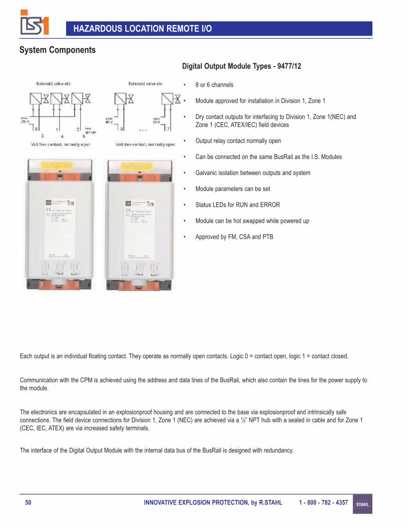
Each output is an individual floating contact. They operate as normally open contacts. Logic 0 = contact open, logic 1 = contact closed.
Communication with the CPM is achieved using the address and data lines of the BusRail, which also contain the lines for the power supply tothe module.
The interface of the Digital Output Module with the internal data bus of the BusRail is designed with redundancy.
Digital Output Module Type - 9477/15
System Components
INNOVATIVE EXPLOSION PROTECTION, by R.STAHL 1 - 800 - 782 - 4357 49
HAZARDOUS LOCATION REMOTE I/O
Order Code
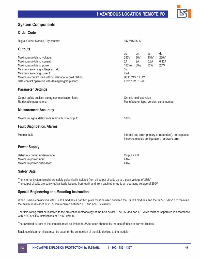
Digital Output Module, Dry contact: 9477/15-08-12
Outputsac dc dc dc
Maximum switching voltage: 250V 30V 110V 220VMaximum switching current: 2A 2A 0.3A 0.12AMaximum switching power: 100VA 60W 33W 26WMinimum switching voltage ac / dc: 5VMinimum switching current: 2mAMaximum contact load without damage to gold plating: Up to 24V / 1.5WSafe contact operation with damaged gold plating: From 12V / 1.5W
Parameter Settings
Output safety position during communication fault: On, off, hold last valueRetrievable parameters: Manufacturer, type, version, serial number
Measurement Accuracy
Maximum signal delay from internal bus to output: 10ms
Fault Diagnostics, Alarms
Module fault: Internal bus error (primary or redundant), no responseIncorrect module configuration, hardware error
Power Supply
Behaviour during undervoltage: Output = OffMaximum power input: 4.8WMaximum power dissipation: 4.8W
Safety Data
The internal system circuits are safely galvanically isolated from all output circuits up to a peak voltage of 375VThe output circuits are safely galvanically isolated from earth and from each other up to an operating voltage of 250V
Special Engineering and Mounting Instructions
When used in conjunction with I.S. I/O modules a partition plate must be used between the I.S. I/O modules and the 9477/15-08-12 to maintainthe minimum distance of 2”, 50mm required between I.S. and non I.S. circuits.
The field wiring must be installed to the protection methodology of the field device. The I.S. and non I.S. wires must be separated in accordancewith NEC or CEC installations or EN 60 079-14.
The switched current of the contacts must be limited to 2A for each channel by the use of fuses or current limiters.
Black combicon terminals must be used for the connection of the field devices to the module.
System Components
INNOVATIVE EXPLOSION PROTECTION, by R.STAHL 1 - 800 - 782 - 435750
HAZARDOUS LOCATION REMOTE I/O
Digital Output Module Types - 9477/12
System Components
• 8 or 6 channels
• Module approved for installation in Division 1, Zone 1
• Dry contact outputs for interfacing to Division 1, Zone 1(NEC) andZone 1 (CEC, ATEX/IEC) field devices
• Output relay contact normally open
• Can be connected on the same BusRail as the I.S. Modules
• Galvanic isolation between outputs and system
• Module parameters can be set
• Status LEDs for RUN and ERROR
• Module can be hot swapped while powered up
• Approved by FM, CSA and PTB
Each output is an individual floating contact. They operate as normally open contacts. Logic 0 = contact open, logic 1 = contact closed.
Communication with the CPM is achieved using the address and data lines of the BusRail, which also contain the lines for the power supply tothe module.
The electronics are encapsulated in an explosionproof housing and are connected to the base via explosionproof and intrinsically safeconnections. The field device connections for Division 1, Zone 1 (NEC) are achieved via a ½” NPT hub with a sealed in cable and for Zone 1(CEC, IEC, ATEX) are via increased safety terminals.
The interface of the Digital Output Module with the internal data bus of the BusRail is designed with redundancy.

INNOVATIVE EXPLOSION PROTECTION, by R.STAHL 1 - 800 - 782 - 4357 51
HAZARDOUS LOCATION REMOTE I/O
System Components
Order Code
Digital Output Module, Dry contact 8 channels: 9477/12-08-12Base for 9477/12-08-12 (NEC): 9490/12-33Base for 9477/12-08-12 (ATEX/IEC, CEC): 9490/11-33Digital Output Module, Dry contact 6 channels: 9477/12-06-12Base for 9477/12-06-12 (NEC): 9490/12-34Base for 9477/12-06-12 (ATEX/IEC, CEC): 9490/11-34
Enclosure wall conduit entry assembly: 9491/00-13-70
Outputs
Minimum switching voltage ac / dc: 5VMinimum switching current: 2mAMaximum contact load without damage to gold plating: Up to 24V / 1.5WSafe contact operation with damaged gold plating: From 12V / 1.5W
9477/12-08-12 ac dcMaximum switching voltage: 60V 30VMaximum switching current: 2A 2AMaximum switching power: 100VA 60W
9477/12-06-12 ac dc dc dcMaximum switching voltage: 250V 30V 110V 220VMaximum switching current: 2A 2A 0.3A 0.12AMaximum switching power: 100VA 60W 33W 26W
Parameter Settings
Output safety position during communication fault: On, off, hold last valueRetrievable parameters Manufacturer, type, version, serial number
Measurement Accuracy
Maximum signal delay from internal bus to output: 10ms
Fault Diagnostics, Alarms
Module fault: Internal bus error (primary or redundant), no responseIncorrect module configuration, hardware error
Power Supply
Behaviour during undervoltage: Output = Off9477/12-08-12 9477/12-06-12
Maximum power input: 4.8W 3.6WMaximum power dissipation: 4.8W 3.6W
Safety Data
Maximum safe area voltage: 250V

INNOVATIVE EXPLOSION PROTECTION, by R.STAHL 1 - 800 - 782 - 435752
HAZARDOUS LOCATION REMOTE I/O
Zone 1 (ATEX/IEC, CEC) Base Type 9490/11
Division 1, Zone 1 (NEC) BaseType 9490/12
Special Engineering and Mounting Instructions
The field wiring must be installed to the protection methodology of the field device. The I.S. and non I.S. wires must be separated in accordance with NEC or CEC installations or EN 60 079-14.
The switched current of the contacts must be limited to 2A for each channel by the use of fuses or current limiters.
For an installation in Division 1, Zone 1 (NEC) a standard enclosure with rating NEMA 4, 4x, IP66 may be used. The enclosure wall conduitentry assembly must be used.
For an installation in Zone 1 (CEC, IEC) an enclosure with protection class Ex e, EEx e must be used.
System Components

INNOVATIVE EXPLOSION PROTECTION, by R.STAHL 1 - 800 - 782 - 4357 53
HAZARDOUS LOCATION REMOTE I/O

INNOVATIVE EXPLOSION PROTECTION, by R.STAHL 1 - 800 - 782 - 435754
HAZARDOUS LOCATION REMOTE I/O
• 16 channels
• Installation in nonhazardous locations only
• No explosion protection
• Galvanic isolation between inputs and system
• Module parameters can be set
• Two channels can be set for frequency input or counter up to 20 kHz
• Status LEDs for RUN and ERROR
• Connection of the field cables to plug-in terminals
• Module can be hot swapped while powered up
The inputs are passive voltage inputs for 0 ... 24V signals. All 16 channels have a common 0V reference.
Channels 14 and 15 are equipped with a fast comparator and may be used for frequency measurement or as counters. This parameter is setduring the configuration of an IS 1 field station. In this mode of operation, the input signals of channels 14 and 15 are also transferred into thedata word for the digital inputs.
Communication with the CPM is achieved using the address and data lines of the BusRail, which also contain the lines for the power supply tothe module.
The interface of the Nonhazardous Digital Input Module with the internal data bus of the BusRail is designed with redundancy.
System Components
Nonhazardous Digital Input Module Type - 9471
+24 V
0 V
0 1 2 3 . . . 15
Voltage Signal 0 / 24V

INNOVATIVE EXPLOSION PROTECTION, by R.STAHL 1 - 800 - 782 - 4357 55
HAZARDOUS LOCATION REMOTE I/O
Order Code
Nonhazardous Digital Input Module, 24V passive inputs: 9471/10-16-11
Inputs
Channels 0 ... 15:Measured variable: VoltageMinimum voltage - On: 13VMinimum voltage - Off: 5VSwitching threshold: 8V ... 10VMaximum voltage: 30VHysteresis: 2VInternal resistance: 6kΩMinimum pulse width: 1ms
Channels 14 and 15 - frequency input or counter:Maximum switching frequency, only with push-pull transmitter: 20kHz
(See system illustration below)
Maximum line length is reduced for frequencies > 1kHz Approx 246ft, 75m at 5kHzMinimum pulse width: 25μsControl signals for counter: Start, stop, resetCounter range: 0 ... 65535
Parameter Settings
Retrievable parameters: Manufacturer, type, version, serial numberChannels 0 ... 15:Invert the input value: On, off
all channels (standard parameter set)per channel (extended parameter set)
Pulse lengthening: 0s, 0.6s, 1.2s, 2.4sper channel group (ch 0 ... 3, ch 4 ... 15 - standard parameter set)per channel (extended parameter set)
Channels 14 and 15 - frequency input or counter:Measuring range frequency: 1Hz ... 1kHz, 1Hz ... 20kHzGate time for frequency 1Hz ... 20kHz: 50ms, 200ms, 1sActive edge for counter: Positive, negative
System Components
+24 V 0 V
1415

INNOVATIVE EXPLOSION PROTECTION, by R.STAHL 1 - 800 - 782 - 435756
HAZARDOUS LOCATION REMOTE I/O
Measurement Accuracy
Maximum delay from the inputs to the internal bus:Channels 0 ... 15: 1msChannels 14 and 15 - counter input: 2msChannels 14 and 15 - frequency input, 1Hz ... 1KHz:
frequency = 1Hz ... 35Hz: 2ms + 1/ffrequency = 35Hz ...1KHz: 34ms + 1/f
Channels 14 and 15 - frequency input, 1Hz ... 20kHz:gate time - 50ms: 50msgate time - 200ms: 200msgate time - 1s: 1s
Channels 14 and 15 - counter or frequency input:Resolution frequency, 1Hz ... 1kHz: 0.05HzResolution frequency, 1Hz ... 20kHz: 1HzAccuracy: 0.02%
Fault Diagnostics, Alarms
Module fault: Internal bus error (primary or redundant), no responseIncorrect module configuration, hardware error
Power Supply
Maximum power input: 1.4WMaximum power dissipation: 3.8W
Special Engineering and Mounting Instructions
The Digital Input module 9471 has no explosion protection and is only suitable for mounting in a nonhazardous location.
The module can not be operated on the same BusRail as the Ex i I/O modules when they are interfacing to field signals in a hazardous location.
A 2A fuse or current limiters is recommended to be used for each fieldstation.
System Components

INNOVATIVE EXPLOSION PROTECTION, by R.STAHL 1 - 800 - 782 - 4357 57
HAZARDOUS LOCATION REMOTE I/O

INNOVATIVE EXPLOSION PROTECTION, by R.STAHL 1 - 800 - 782 - 435758
HAZARDOUS LOCATION REMOTE I/O
• Backplane bus for the IS 1 system
• Installation in Division 1, Zone 1, Division 2, Zone 2 andNonhazardous Locations
• Installation in 35 x 15mm DIN rails
• Length for 2 or 4 modules
• BusRail can be built up over several segments
• End caps and connection cables for extendability
• Passive component with high reliability
• Approved by FM, CSA, PTB, VNIIEF, BKI, EVPU, FTZU and DNV
The BusRail fits into a 35 x 15mm DIN rail and provides the internal electrical connection between the CPM and the I/O modules. The BusRailis a purely passive design. It consists of the internal data bus, the PowerBus and the address lines for the I/O modules.
The internal bus is designed with redundancy and the PowerBus has very high availability.
The BusRail is available in different lengths, for 2 or 4 modules, which can be connected together to form a segment of the required length. Theuse of a connection cable permits several BusRail segments to be built up in one enclosure. End caps are required both at the beginning and atthe end of each segment.
System Components
BusRail Components Type 9494

INNOVATIVE EXPLOSION PROTECTION, by R.STAHL 1 - 800 - 782 - 4357 59
HAZARDOUS LOCATION REMOTE I/O
Order Code
BusRail 4 modules: 9494/S1-M4BusRail 2 modules, begin: 9494/S1-B2BusRail 2 modules, end: 9494/S1-E2BusRail End Cap, begin: 9494/A1-B0BusRail End Cap, end: 9494/A1-E0BusRail End Cap, begin Sub-D: 9494/A2-B0BusRail End Cap, end Sub-D: 9494/A2-E0Connection cable - 43.3”, 1.1m: 9491/Z0-VBConnection cable - 18.5”, 0.47m: 9491/Z0-VB 0.47
Technical Data
9494/S1-M4 9494/S1-B2 9494/S1-E2Number of module slots: 4 2 2Extendable at the beginning: yes no yesExtendable at the end: yes yes noInternal redundant data bus: yes yes yesNumber of address lines: 6 6 6Highly reliable power supply lines: yes yes yes
Maximum BusRail length including connection cable: 9ft 9”, 3mDIN rail for BusRail installation: DIN EN 50 022, 35 x 15mm
System Components

INNOVATIVE EXPLOSION PROTECTION, by R.STAHL 1 - 800 - 782 - 435760
HAZARDOUS LOCATION REMOTE I/O
System Accessories
Fieldbus Connectors
• 9 pin Sub-D connectors for connection of the fieldbus and the ServiceBus to the CPM
• Three versions - Division 1, Zone 1 installations RS 485 Ex i- Division 1, Zone 1 installations RS 485 IS- Division 2, Zone 2 and Nonhazardous installations
• Terminating resistors are included and can be switched on or off
Field Signal Connections
• 14AWG, 2.5mm² plug-in terminals, 16-pin
• Screw or spring connection types
• Blue:connection of intrinsically safe field signals to the I/O modules.
• Black:connection of non intrinsically safe signals to the I/O modules.
Partition
• To provide the necessary creepage and clearance between intrinsically safe wiring and non intrinsically safe wiring on adjacent I/O modules.
Software and Documentation
• Profibus DP Manual for IS 1
• Profibus GSD files on 3½ ” diskette
• Modbus RTU Manual for IS 1
• “I.S. Wizard” Software Manual
• “I.S. Wizard” Software on CD
• IS 1 Installation and Operating Manual
• Galvanic Isolator / Converter Data Sheets
• RS 485 Installation Manual
Additional documentation available upon request.

INNOVATIVE EXPLOSION PROTECTION, by R.STAHL 1 - 800 - 782 - 4357 61
HAZARDOUS LOCATION REMOTE I/O
System Accessories
Fieldbus Isolating Repeater Type - 9185
• Associated apparatus for installation in Division 2, Zone 2 andnonhazardous locations
• Selectable interface to the automation system - RS 232, RS 422 or RS 485
• Selectable baud rate - 1.2kBit/s up to 1.5MBit/s
• Power supply 18 ... 31.2Vac/dc, 66mA
Type - 9185/11-35-10
• Intrinsically safe bus segment RS 485 Ex i or RS 485 IS, selectable via DIP switches. Suitable for Profibus DP and Modbus RTU
• Automatic baud rate detection (only with Profibus DP)
Type - 9185/12-45-10
• For the ServiceBus communication link to the Division 2, Zone 2 CPM
Fieldbus Isolating Repeater Type - 9186/12-11-11
• For use with fiber optic up to 6,500ft, 2,000m in length
• Transmission speed - 1.2kBit/s up to 1.5MBit/s
• Approved for installation in Zone 1 and Zone 2 (ATEX/IEC).
• Pending: Approved for installation in Class 1 Zone 1 and Division 2(NEC, CEC)
• Increased Safety connections for the power supply 24Vdc, 80mA
• Converts intrinsically safe copper to intrinsically safe fiber optic andvice versa
• Connection structures possible: Ring, Line and Point to Point
• Redundant connection possible with automatic switchover

INNOVATIVE EXPLOSION PROTECTION, by R.STAHL 1 - 800 - 782 - 435762
HAZARDOUS LOCATION REMOTE I/O
System Accessories
Order Codes
Screw terminal, Blue Labeled “1 ... 16”: 9490/00-46-70Screw terminal, Blue Labeled “17 ... 32”: 9490/00-46-70AScrew terminal, Black Labeled “1 ... 16”: 9490/00-16-70Screw terminal, Black Labeled “17 ... 32”: 9490/00-16-70ASpring terminal, Blue Labeled “1 ... 16”: 9490/00-26-70Spring terminal, Blue Labeled “17 ... 32”: 9490/00-26-70ASpring terminal, Black Labeled “1 ... 16”: 9490/00-36-70Spring terminal, Black Labeled “17 ... 32”: 9490/00-36-70A
Partition: 9490/90-15-40
Dust Covers for unused BusRail slots: 9494/90-11-40
RS 485 Ex i Fieldbus and ServiceBus connector, Division 1, Zone 1: 9490/00-32-20RS 485 IS Fieldbus and ServiceBus connector, Division 1, Zone 1: 9490/00-22-20Fieldbus and ServiceBus connector, Division 2, Zone 2, Nonhazardous: 3157/32-00-00
Profibus GSD files: 9499/00-20-10“I.S. Wizard” Software:
Demo, up to 6 Modules: 9499/00-30-10Modbus RTU, any modules, no diagnosis: 9499/00-40-10Up to 20 modules: 9499/00-80-10Up to 20 modules, print labels: 9499/00-50-10Up to 100 modules: 9499/00-90-10Up to 100 modules, print labels: 9499/00-60-10Over 100 modules: 9499/01-00-10Over 100 modules, print labels: 9499/00-70-10
Documentation binder, please specify contents: 9400/Docs
Fieldbus isolating repeater for communication links to Division 1, Zone 1 CPM: 9185/11-35-10Fieldbus isolating repeater for the ServiceBus connection in Division 2, Zone 2: 9185/12-45-10Fieldbus isolating repeater for fiber optic communicaiton links: 9186/12-11-11
Labeling strips for BusRail (1 sheet, 14 sets): 9490/90-58-50Warning label “Clean modules only with a damp cloth”: 9490/90-68-50I/O module label “Do not use for I.S. circuits”: 9490/91-18-50Perforated sheets for I/O module labels, printed from “I.S. Wizard”: 9490/00-18-50

INNOVATIVE EXPLOSION PROTECTION, by R.STAHL 1 - 800 - 782 - 4357 63
HAZARDOUS LOCATION REMOTE I/O
System AccessoriesThe IS 1 remote I/O is a component based, plug and play system. For installations in Division 1, Zone 1 (NEC) and Division 2, Zone 2 (all codesand standards) the system can be integrated into any type of field enclosure. For installations in Zone 1 (CEC, ATEX/IEC) the system must be integrated into an Ex e, EEx e type enclosure. For all installations the type of enclosure used must be suitable for the environment of the particular installation.
R.Stahl Field Enclosure Types - 8125, 8126 and 8146
• Modular enclosure systems in three material versions316 stainless steel - 8125304 stainless steel - 8126glass fiber reinforced polyester - 8146
• Impact resistance > 7Nm
• Protection class Exe, EEx e, NEMA 4, 4X, IP66
• Identical enclosure systems available for terminal boxesand control panels which can be installed in Division 1, Zone 1, Division 2, Zone 2
Customer Specific Field Enclosures
The IS 1 system can be integrated into field enclosures inaccordance with customer requirements.
Custom Solutions
R.Stahl offers complete solutions, from the design and engineering to customer specific documentation.
• Project specific variations can be engineeredsizesconduit entries, cable glandsflange plates
• Project specific solutions can be integratedinstallation of power suppliesmarshalling, terminals, pilot lightsswitches, indicatorssystems, etc.
• Extensive range of accessories grounding barscable clampsbreather glandsanti-condensation heatersframe systems for mounting the enclosures
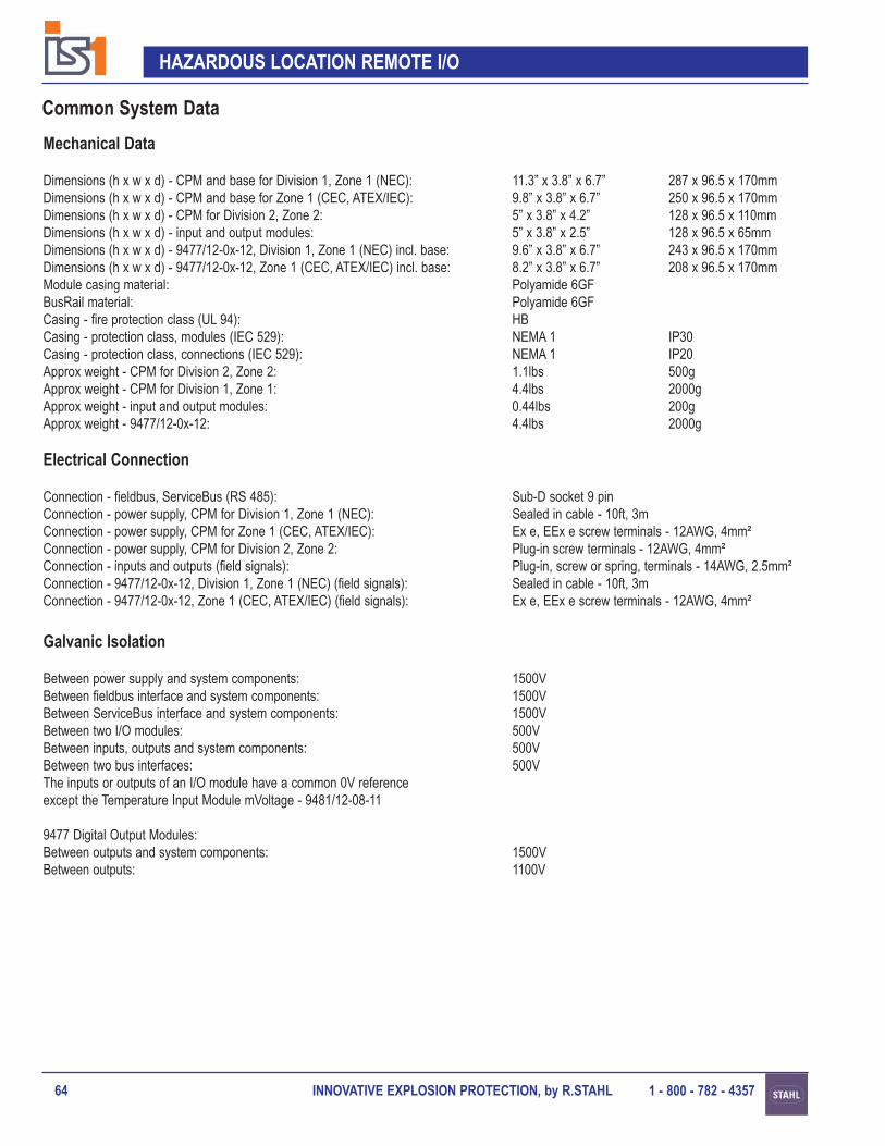
INNOVATIVE EXPLOSION PROTECTION, by R.STAHL 1 - 800 - 782 - 435764
HAZARDOUS LOCATION REMOTE I/O
Mechanical Data
Dimensions (h x w x d) - CPM and base for Division 1, Zone 1 (NEC): 11.3” x 3.8” x 6.7” 287 x 96.5 x 170mmDimensions (h x w x d) - CPM and base for Zone 1 (CEC, ATEX/IEC): 9.8” x 3.8” x 6.7” 250 x 96.5 x 170mmDimensions (h x w x d) - CPM for Division 2, Zone 2: 5” x 3.8” x 4.2” 128 x 96.5 x 110mmDimensions (h x w x d) - input and output modules: 5” x 3.8” x 2.5” 128 x 96.5 x 65mmDimensions (h x w x d) - 9477/12-0x-12, Division 1, Zone 1 (NEC) incl. base: 9.6” x 3.8” x 6.7” 243 x 96.5 x 170mmDimensions (h x w x d) - 9477/12-0x-12, Zone 1 (CEC, ATEX/IEC) incl. base: 8.2” x 3.8” x 6.7” 208 x 96.5 x 170mmModule casing material: Polyamide 6GFBusRail material: Polyamide 6GFCasing - fire protection class (UL 94): HBCasing - protection class, modules (IEC 529): NEMA 1 IP30Casing - protection class, connections (IEC 529): NEMA 1 IP20Approx weight - CPM for Division 2, Zone 2: 1.1lbs 500gApprox weight - CPM for Division 1, Zone 1: 4.4lbs 2000gApprox weight - input and output modules: 0.44lbs 200gApprox weight - 9477/12-0x-12: 4.4lbs 2000g
Electrical Connection
Connection - fieldbus, ServiceBus (RS 485): Sub-D socket 9 pinConnection - power supply, CPM for Division 1, Zone 1 (NEC): Sealed in cable - 10ft, 3mConnection - power supply, CPM for Zone 1 (CEC, ATEX/IEC): Ex e, EEx e screw terminals - 12AWG, 4mm²Connection - power supply, CPM for Division 2, Zone 2: Plug-in screw terminals - 12AWG, 4mm²Connection - inputs and outputs (field signals): Plug-in, screw or spring, terminals - 14AWG, 2.5mm²Connection - 9477/12-0x-12, Division 1, Zone 1 (NEC) (field signals): Sealed in cable - 10ft, 3mConnection - 9477/12-0x-12, Zone 1 (CEC, ATEX/IEC) (field signals): Ex e, EEx e screw terminals - 12AWG, 4mm²
Galvanic Isolation
Between power supply and system components: 1500VBetween fieldbus interface and system components: 1500VBetween ServiceBus interface and system components: 1500VBetween two I/O modules: 500VBetween inputs, outputs and system components: 500VBetween two bus interfaces: 500VThe inputs or outputs of an I/O module have a common 0V referenceexcept the Temperature Input Module mVoltage - 9481/12-08-11
9477 Digital Output Modules:Between outputs and system components: 1500VBetween outputs: 1100V
Common System Data

INNOVATIVE EXPLOSION PROTECTION, by R.STAHL 1 - 800 - 782 - 4357 65
HAZARDOUS LOCATION REMOTE I/O
Common System Data
Installation Conditions
Mounting type: 35 x 15mm DIN railMounting position: Horizontal or vertical (not upside down)Mounting location (dependent on the CPM): Nonhazardous, Division 2, Zone 2, Division 1, Zone 1Protection class of the field enclosure for installation in:
NEC: - Nonhazardous, Class 1, Division 1 and 2, Zone 1 and 2 : NEMA 4, 4X, IP66NEC: - Class II, Division 1 and Division 2, Class III locations: NEMA 9CEC: - Class 1 Zone 1 and Division 2 Locations with 9440/x2: Ex eCEC: - Class 1 Zone 2 Locations with 9440/15: Suitable enclosure per the authroity having jurisdictionATEX/IEC: - Zone 2 Locations: NEMA 4, 4X, IP54 suitable for Zone 2ATEX/IEC: - Zone 1 Locations: EEx e
Ambient Conditions
Ambient temperature - modules: -4ºF ... +149ºF, -20ºC ... +65ºCAmbient temperature - field station (engineering dependent): -4ºF ... +122ºF, -20ºC ... +50ºC
Do not expose to direct sunlightStorage temperature for modules: -40ºF ... +158ºF, -40ºC ... +70ºCMaximum relative humidity (no condensation): 95%Shock, sinusoidal half wave (IEC 60068-2-27): 15g (3 shocks per axis and direction)Vibration, sinusoidal (IEC 60068-2-6): 1g in frequency range 10Hz ... 500Hz
2g in frequency range 45Hz ... 100HzElectromagnetic compatibility tested in accordance with: EN 61 326-1 (1998),
IEC 1000-4-1...6, NAMUR NE 21
MTBF
9440/15-01-11 - CPM for Division 2, Zone 2: 7.7 years9440/x2-01-x1 - CPM for Division 1, Zone 1, inclusive base: 5.6 years9460/12-08-11 - Analog Input Module: 20.4 years9461/12-08-x1 - Analog Input Module HART: 19.3 years9480/12-08-11 - Temperature Input Module Resistance: 39.36 years @ 104ºF, 40ºC9481/12-08-11 - Temperature Input Module mVoltage: 12.9 years9465/12-08-11 - Analog Output Module: 17.6 years9466/12-08-11 - Analog Output Module HART: 16.8 years9470/22-16-11 - Digital Input Module: 25.1 years9471/10-16-11 - Nonhazardous Digital Input Module: 25 years9475/12-04-x1 - Digital Output Module, 4 channel: 20.8 years9475/12-08-x1 - Digital Output Module, 8 channel: 18.4 years9477/15-08-12 - Digital Output Module, Dry contact: 40.75 years @ 122ºF, 50ºC9477/12-08-12 - Digital Output Module, Dry contact, 8 channel: 40.75 years @ 122ºF, 50ºC9477/12-06-12 - Digital Output Module, Dry contact, 6 channel: 40.75 years @ 122ºF, 50ºC

INNOVATIVE EXPLOSION PROTECTION, by R.STAHL 1 - 800 - 782 - 435766
HAZARDOUS LOCATION REMOTE I/O
Common System Data
Dimensions
CPM and Base - Division 1, Zone 1
Division 1, Zone 1 (NEC) Base
Zone 1 (CEC, ATEX/IEC) base

INNOVATIVE EXPLOSION PROTECTION, by R.STAHL 1 - 800 - 782 - 4357 67
HAZARDOUS LOCATION REMOTE I/O
Dimensions
Common System Data
CPM - Division 2, Zone 2, Nonhazardous
I/O Modules
DOM and Base - Division 1, Zone 1

INNOVATIVE EXPLOSION PROTECTION, by R.STAHL 1 - 800 - 782 - 435768
HAZARDOUS LOCATION REMOTE I/O
Common System Data
Dimensions
BusRail
Zone 1 (ATEX/IEC) base
Division 1, Zone 1 (NEC) base
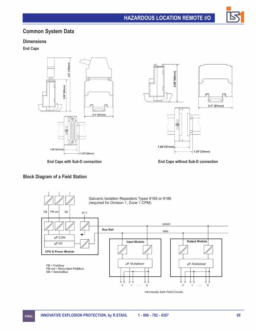
INNOVATIVE EXPLOSION PROTECTION, by R.STAHL 1 - 800 - 782 - 4357 69
HAZARDOUS LOCATION REMOTE I/O
Common System Data
DimensionsEnd Caps
End Caps with Sub-D connection End Caps without Sub-D connection
Block Diagram of a Field Station

INNOVATIVE EXPLOSION PROTECTION, by R.STAHL 1 - 800 - 782 - 435770
HAZARDOUS LOCATION REMOTE I/O
Common System Data
Engineering Examples
Enclosure Size: 24” x 24”
1 x CPM - 9440/15 with up to 7 I/O Modules
Suitable for installation in Division 2, Zone 2
Enclosure Size: 48” x 36”
1 x CPM - 9440/15 with up to 16 I/O Modules
Suitable for installation in Division 2, Zone 2

INNOVATIVE EXPLOSION PROTECTION, by R.STAHL 1 - 800 - 782 - 4357 71
HAZARDOUS LOCATION REMOTE I/O
Common System Data
Engineering Examples
Enclosure Size: 24” x 30”
1 x CPM - 9440/12 or 9440/22with up to 7 I/O Modules
Suitable for installation in Division 1,Zone 1 (NEC)
Enclosure Size: 48” x 36”
2 x CPMs - 9440/12 or 9440/22with up to 8 I/O Modules each
Suitable for installation in Division 1,Zone 1 (NEC)

INNOVATIVE EXPLOSION PROTECTION, by R.STAHL 1 - 800 - 782 - 435772
HAZARDOUS LOCATION REMOTE I/O
IS 1 Components
North America - FM and CSA Approval
FM Approval: 3007532
When installed in accordance with Control Drawing 94 006 01 31 0
Inputs and outputs:Intrinsically safe connections to Class I, II, III, Division 1, Groups A - G,
Class I, Zone 0, Group IIC.Input and output modules:
Intrinsically safe for installation in Class I, II, III, Division 1, Groups A - G, T4Class I, Zone 1, Group IIC, T4.
CPM and output module 9477/12:Explosionproof for installation in Class I, II, III Division 1, Groups A - G, T6
Class I, Zone 1, Group IIC, T4.Intrinsically safe field circuits to Class I, II, III, Division 1, Groups A - G,
Class I, Zone 1, Group IIC.BusRail:
Intrinsically safe for installation in Class I, II, III Division 1, Groups A - G, T4Class I, Zone 1, Group IIC, T4.
Fieldbus:Intrinsically safe connection to Class I, II, III Division 1, Groups A - G,
Class I, Zone 1, Group IIC.
When installed in accordance with Control Drawing 94 006 02 31 0
Inputs and outputs:Intrinsically safe connections to Class I, II, III, Division 1, Groups A - G,
Class I, Zone 0, Group IIC.Input and output modules:
Nonincendive for installation in Class I, II, III Division 2, Groups A - G, T6Class I, Zone 2, Group IIC, T6
CPM and output module 9477/15:Nonincendive for installation in Class I, II, III Division 2, Groups A - G, T6
Class I, Zone 2, Group IIC, T6Nonincendive field circuits to Class I, II, III, Division 2, Groups A - G,
Class I, Zone 2, Group IIC.BusRail:
Nonincendive for installation in Class I, II, III Division 2, Groups A - G, T6Class I, Zone 2, Group IIC, T6
Fieldbus:Nonincendive connection to Class I, II, III, Division 2, Groups A - G,
Class I, Zone 2, Group IIC.
Certifications and Approvals

INNOVATIVE EXPLOSION PROTECTION, by R.STAHL 1 - 800 - 782 - 4357 73
HAZARDOUS LOCATION REMOTE I/O
IS 1 Components
North America - FM and CSA Approval
CSA Approval: 1519624
When installed in accordance with Control Drawing 94 006 01 31 2
Inputs and Outputs:Intrinsically safe connections to Class I, Zone 0, Group IIC.
Input and Output modules:Intrinsically safe for installation in Class I, Zone 1, Group IIC, T4.
CPM:Explosionproof for installation in Class I, Zone 1, Group IIC, T4.Intrinsically safe field circuits to Class I, Zone 1, Group IIC.
BusRail:Intrinsically safe for installation in Class I, Zone 1, Group IIC, T4.
Fieldbus:Intrinsically safe connection to Class I, Zone 1, Group IIC.
When installed in accordance with Control Drawing 94 006 02 31 2
Inputs and Outputs:Intrinsically safe connections to Class I, Zone 0, Group IIC.
Input and Output modules:Nonincendive for installation in Class I, Zone 2, Group IIC, T6
CPM:Nonincendive for installation in Class I, Zone 2, Group IIC, T6Nonincendive field circuits to Class I, Zone 2, Group IIC.
BusRail:Nonincendive for installation in Class I, Zone 2, Group IIC, T6
Fieldbus:Nonincendive connection to Class I, Zone 2, Group IIC.
Certifications and Approvals

INNOVATIVE EXPLOSION PROTECTION, by R.STAHL 1 - 800 - 782 - 435774
HAZARDOUS LOCATION REMOTE I/O
IS 1 Components
Europe - PTB, SEV, VNIIEF, BKI, EVPU, FTZU and DNV Certification
PTB (Germany) and SEV (Switzerland)
9440/15-01-11 - CPM for installation in a nonhazardous location: II (2) G, [EEx [ia/ib]] IIC/IIBPTB 99 ATEX 2222
9440/15-01-11 - CPM for Zone 2: II 3 G, EEx nA II T4ASEV 99 ATEX 10404 XASEV 99 ATEX 10404 U
9440/12-01-11 - CPM for Zone 1 incl. base: II 2 G, EEx e d [ia, ib] IIC T4PTB 00 ATEX 2052
Inputs and Outputs: EEx ia IIC/IIB or EEx ib IIC/IIBInput and Output modules: II 2 (1) G, EEx ib [ia] IIC/IIB T4
9460/12-08-11 - Analog Input Module: PTB 99 ATEX 21759461/12-08-11 - Analog Input Module HART: PTB 99 ATEX 21759461/12-08-21 - Analog Input Module HART: PTB 99 ATEX 21759480/12-08-11 - Temperature Input Module Resistance: PTB 99 ATEX 21239481/12-08-11 - Temperature Input Module mVoltage: PTB 99 ATEX 21249465/12-08-11 - Analog Output Module: PTB 99 ATEX 22079466/12-08-11 - Analog Output Module HART: PTB 99 ATEX 22079470/22-16-11 - Digital Input Module: PTB 99 ATEX 21849475/12-04-x1 - Digital Output Module, 4 channel: PTB 99 ATEX 22209475/12-08-x1 - Digital Output Module, 8 channel: PTB 99 ATEX 2220
9477/1x-0x-12 - Digital Output Modules, Dry contacts:9477/15-08-12 - Zone 2 installation: PTB 01 ATEX 2187Module: II (2) G [EEx [ib/ia]] IIC
II (3) G EEx nACL IIC T49477/12-0x-12 - Zone 1 installation: PTB 01 ATEX 2205Module: II 2 G EEx d e [ib/ia] IIB/IIC T4
Fieldbus for Zone 1: SYST EEx ib IIC/IIB T6PTB Ex 96 D 2193X
Fieldstation in Zone 2: II 3 (2, 1) G, EEx nA ib [ia] IIC/IIB T4Fieldstation in Zone 1: II 2 (1) G, EEx e d ib [ia] IIC/IIB T4
Certifications and Approvals

INNOVATIVE EXPLOSION PROTECTION, by R.STAHL 1 - 800 - 782 - 4357 75
HAZARDOUS LOCATION REMOTE I/O
IS 1 Components
Europe
VNIIEF (Russia) CTB-549.02
9440/15-01-11 - CPM for Nonhazardous locations and Zone 29440/12-01-11 - CPM for Zone 1 incl. base9460/12-08-11 - Analog Input Module9461/12-08-11 - Analog Input Module HART9461/12-08-21 - Analog Input Module HART9480/12-08-11 - Temperature Input Module Resistance9481/12-08-11 - Temperature Input Module mVoltage9465/12-08-11 - Analog Output Module9466/12-08-11 - Analog Output Module HART9470/22-16-11 - Digital Input Module9475/12-04-x1 - Digital Output Module, 4 channel9475/12-08-x1 - Digital Output Module, 8 channel
BKI (Hungary)
9440/15-01-11 - CPM for Nonhazardous locations and Zone 2 BKI Ex-00.C.2969440/12-01-11 - CPM for Zone 1 incl. base BKI Ex-01.E.0709460/12-08-11 - Analog Input Module BKI Ex-00.C.3289461/12-08-11 - Analog Input Module HART BKI Ex-00.C.3289461/12-08-21 - Analog Input Module HART BKI Ex-00.C.3289480/12-08-11 - Temperature Input Module Resistance BKI Ex-01.E.0919481/12-08-11 - Temperature Input Module mVoltage BKI Ex-01.E.0929465/12-08-11 - Analog Output Module BKI Ex-00.C.2959466/12-08-11 - Analog Output Module HART BKI Ex-00.C.2959470/22-16-11 - Digital Input Module BKI Ex-00.C.3189475/12-04-x1 - Digital Output Module, 4 channel BKI EX-00.C.3279475/12-08-x1 - Digital Output Module, 8 channel BKI EX-00.C.3279477/15-08-12 - Digital Output Module, Relay BKI 02 ATEX 158
EVPU (Slovakia)
9440/15-01-11 - CPM for Nonhazardous locations and Zone 2 04243/101/1/20019460/12-08-11 - Analog Input Module 04242/101/1/20019461/12-08-11 - Analog Input Module HART 04242/101/1/20019461/12-08-21 - Analog Input Module HART 04242/101/1/20019480/12-08-11 - Temperature Input Module Resistance 04244/101/1/2001
Certifications and Approvals

INNOVATIVE EXPLOSION PROTECTION, by R.STAHL 1 - 800 - 782 - 435776
HAZARDOUS LOCATION REMOTE I/O
IS 1 Components
Europe
FTZU (Czech Republic)
9440/15-01-11 - CPM for Nonhazardous locations and Zone 2 FTZU 00 Ex 01549460/12-08-11 - Analog Input Module FTZU 00 Ex 0155X9461/12-08-11 - Analog Input Module HART FTZU 00 Ex 0155X9461/12-08-21 - Analog Input Module HART FTZU 00 Ex 0155X9465/12-08-11 - Analog Output Module FTZU 00 Ex 0147X9466/12-08-11 - Analog Output Module HART FTZU 00 Ex 0147X9470/22-16-11 - Digital Input Module FTZU 00 Ex 0156X9475/12-04-x1 - Digital Output Module, 4 channel FTZU 00 Ex 0157X9475/12-08-x1 - Digital Output Module, 8 channel FTZU 00 Ex 0157X
DNV (Norway) Certification for ships, high speed and light craft and mobile units Cert. No. A-8543
IS 1 System
PTO - Profibus Trade Organisation Certificate
IS 1 with Profibus DP Cert. No. Z00624
IS 1 Accessories
9185 - Fieldbus Isolating Repeater, copper, 1.5MBit/s
FM Approval: 3017145CSA Approval: 1570027BKI Approval: 03Atex339x_unDNV Approval: A-951DMT Approval: 02Atexe246XVNIIEF Approval: 04b00140_ru
Certifications and Approvals

R. STAHL, INC. 9001 Knight Road, Houston TX 77054(800) 782-4357 Fax: (713) 792-9301 www.rstahl.com
RST-75 04/06Printed in USA