HAYWARD GORDON ULC · HAYWARD GORDON ULC ... D. Overheating Stuffing Box ... Always disconnect...
42
HAYWARD GORDON ULC Pumps ·Mixers ·Strainers Engineered Systems and Controls Operation and Maintenance Manual XCS and XCS-VDP SCREW CENTRIFUGAL PUMP HORIZONTAL AND VERTICAL DRY PIT PROJECT: EQUIPMENT: MODEL: QUANTITY: SERIAL #: LOCAL REPRESENTATIVE: DATE: FOR INFORMATION, VISIT: www.haywardgordon.com FOR SERVICE AND INFORMATION, CONTACT: TORONTO Head Office & Plant MONTREAL CALGARY VANCOUVER (US West) 5 Bridgen Gate, Halton Hills, ON L7G 0A3 16755 Hymus Blvd. Kirkland, QC H9H 3L4 #8 6143-4 th St. SE, Calgary, AB T2H 2H9 166 Riverside Dr, North Vancouver, BC V7H 1T9 Tel: (905)-693-8595 (514)-697-6445 (403)-253-2737 (604)-986-8764 Fax: (905)-693-1452 (514)-697-1164 (403)-253-1353 (604)-986-8794 Date of Issue: February 3, 2016
Transcript of HAYWARD GORDON ULC · HAYWARD GORDON ULC ... D. Overheating Stuffing Box ... Always disconnect...

HAYWARD GORDON ULC Pumps ·Mixers ·Strainers
Engineered Systems and Controls
Operation and Maintenance Manual
XCS and XCS-VDP SCREW CENTRIFUGAL PUMP
HORIZONTAL AND VERTICAL DRY PIT
PROJECT:
EQUIPMENT:
MODEL:
QUANTITY:
SERIAL #:
LOCAL REPRESENTATIVE:
DATE:
FOR INFORMATION, VISIT: www.haywardgordon.com FOR SERVICE AND INFORMATION, CONTACT:
TORONTO Head Office & Plant
MONTREAL CALGARY VANCOUVER
(US West)
5 Bridgen Gate, Halton Hills, ON L7G 0A3
16755 Hymus Blvd. Kirkland, QC H9H 3L4
#8 6143-4th St. SE, Calgary, AB T2H 2H9
166 Riverside Dr, North Vancouver, BC V7H 1T9
Tel: (905)-693-8595 (514)-697-6445 (403)-253-2737 (604)-986-8764
Fax: (905)-693-1452 (514)-697-1164 (403)-253-1353 (604)-986-8794
Date of Issue: February 3, 2016
Hayward Gordon ULC Pumps • Mixers·• Strainers
Engineered Systems and Controls
THE HAYWARD GORDON GUARANTEE
HAYWARD GORDON ULC endeavours to supply equipment of the highest quality both in materials and workmanship. However, within one year from date of startup or eighteen (18) months from date of shipment (whichever comes first) if any part of the equipment manufactured by HAYWARD GORDON ULC is proven to have been defective in material or workmanship, HAYWARD GORDON ULC shall have the right and obligation to promptly repair or replace such part F.O.B its works. Pumps or parts to be considered for warranty repair or replacement must be returned freight prepaid to Hayward Gordon’s factory at Halton Hills, ON. We reserve the right to require the return of defective parts before any claim is recognized. Materials are certified to be of the specified composition, however, the materials are not guaranteed against chemical attack or wear. No other warranty or condition, whether statutory or otherwise, is made, intended or to be implied and, except for its obligation to repair or replace defective parts as provided for above, HAYWARD GORDON ULC will not be responsible for any costs or damages, direct or indirect, which may result to the Purchaser from any defect in the equipment (whether of workmanship, material, design or otherwise) or from any breakage or stoppage thereof. Such costs specifically include, but are not limited to, equipment removal, re-installation, and freight. In any event, the liability of HAYWARD GORDON ULC arising through the supply of defective equipment shall not exceed the purchase price of the equipment. For equipment included in this unit but manufactured by others, HAYWARD GORDON ULC will endeavor to assign to the purchaser, the guarantee extended by such manufacturers to HAYWARD GORDON ULC.
No modifications to this guarantee may be extended without the written authorization of a signing officer of HAYWARD GORDON ULC.

Hayward Gordon ULC Pumps • Mixers·• Strainers
Engineered Systems and Controls
____________________________________________________________________________________ XCS Screw Centrifugal Pump Instruction Manual ii
TABLE OF CONTENTS
I. INSTALLATION ............................................................................................................................... I-1 A. Unloading ................................................................................................................................... I-1 B. Inspection ................................................................................................................................... I-1 C. Storage ....................................................................................................................................... I-2 D. Installation .................................................................................................................................. I-2 E. Foundation ................................................................................................................................. I-3 F. Mounting .................................................................................................................................... I-3 G. Alignment ................................................................................................................................... I-4 H. Grouting ..................................................................................................................................... I-5 I. Piping .......................................................................................................................................... I-6 J. Service Connections ................................................................................................................. I-8 K. Final Alignment ........................................................................................................................ I-12
II. OPERATION ................................................................................................................................... II-1 A. Pre-Starting ............................................................................................................................... II-1 B. Initial Starting ............................................................................................................................ II-1 C. Necessary Checks .................................................................................................................... II-2 D. Stopping the pump ................................................................................................................... II-2
III. TROUBLESHOOTING ................................................................................................................... III-1 A. Speed too Low ......................................................................................................................... III-1 B. Vibration – Noise ..................................................................................................................... III-1 C. Overheating Bearings ............................................................................................................. III-2 D. Overheating Stuffing Box ....................................................................................................... III-2 E. No Discharge Flow .................................................................................................................. III-2 F. Not Enough Discharge Flow .................................................................................................. III-3 G. Not Enough Pressure .............................................................................................................. III-4 H. Loss of Prime ........................................................................................................................... III-4 I. High Power Consumption ...................................................................................................... III-4 J. Too Much Stuffing Box Leakage ............................................................................................ III-4
IV. MAINTENANCE ............................................................................................................................ IV-1 A. Oil Lubricated Bearings ......................................................................................................... IV-1 B. Grease Lubricated Bearings ................................................................................................. IV-2 C. Packing .................................................................................................................................... IV-2 D. Mechanical Seal ...................................................................................................................... IV-4 E. Drive ......................................................................................................................................... IV-4 F. Motor ........................................................................................................................................ IV-4 G. Preventative Maintenance Schedule .................................................................................... IV-5
V. SERVICE & REPAIR ...................................................................................................................... V-1 A. Disassembly of Pump ............................................................................................................. V-1 B. Parts Inspection ....................................................................................................................... V-4 C. Reassembly of Pump .............................................................................................................. V-4 D. Parts Inventory Guide ........................................................................................................... V-12 E. Parts Ordering ....................................................................................................................... V-13
VI. DRAWINGS ................................................................................................................................... VI-1

Hayward Gordon ULC Pumps • Mixers·• Strainers
Engineered Systems and Controls
____________________________________________________________________________________ XCS Screw Centrifugal Pump Instruction Manual I-1
I. INSTALLATION
CAUTION!
Before putting pump into service carefully study and adhere to all sections of this manual, as this is necessary for safe and satisfactory operation of your new Hayward Gordon Pump.
This pump has components with sharp edges and pinch areas that can cause cuts. Always wear protective gloves when working on or around the pump.
Always disconnect electrical power and lock out the motor starter before performing any work on the pump/motor unit. On duplex pumps with alternating relays, both starters must be locked out regardless of which pump is being worked on.
A. Unloading
Care must be taken when unloading pump. Unit must be lifted from all four lifting points in each corner of the base.
CAUTION!
An adequately sized crane or hoist must be used to lift unit.
All lifting equipment (i.e., chains, hooks and eyes) must be in accordance with local or federal safety codes.
Failure to use approved lifting equipment may result in serious injury.
B. Inspection
Inspection should be performed immediately after unloading pump. Examine equipment for broken, cracked, bent or missing parts. Carefully check:
1. Base
2. Motor, pump feet, coupling and flanges
3. Shafts
4. Motor end bells, eyebolts, conduit box.
Report all damage or loss to the transportation company and Hayward Gordon ULC.
Hayward Gordon ULC Pumps • Mixers·• Strainers
Engineered Systems and Controls
____________________________________________________________________________________ XCS Screw Centrifugal Pump Instruction Manual I-2
C. Storage
If the pump is not to be installed and operated shortly after arrival (more than two weeks), sufficient preparation for storage should be made.
1. Inspect pump on skid or open crate if applicable and check for any signs of damage due to shipment.
2. Remove glands, packing and lantern ring from stuffing box. If pump is fitted with a mechanical seal, ensure seal faces are dry.
3. Protect exposed steel parts with a rust preventative.
4. Cover pump suction, discharge and all opening with masking tape, wood or cardboard.
5. Store pump in a dry location, protected from moisture, dirt, dust, pests and vibrations or rattles.
6. Cover pump with tarpaulin if area has no protective covering.
7. Rotate shaft every week to prevent pitting of bearing surfaces. Monthly inspections are recommended.
8. Re-grease motor bearings (if applicable) every six months and rotate the shaft by hand every week.
9. For pumps with grease lubricated bearings, re-grease at six month intervals.
10. For pumps with oil lubricated bearings, remove the vent at the top of the bearing housing and fill the chamber completely with 20W non-detergent oil which contains rust inhibitors. Replace the vent after filling. Before starting the pump, drain the oil to the recommended level and run for two minutes. Stop the pump and drain completely of oil. Refill the bearing housing with new oil; refer to Section IV.A – Oil Lubricated Bearings for recommended oils and quantities.
D. Installation
Allow ample space for maintenance and inspection. Provide headroom and ventilation in a dry location. Do not locate near dangerous or harmful elements or temperatures. Install as near to liquid source as possible. Use shortest possible direct suction pipe. Keep discharge piping direct with minimum of elbows (long radius preferred) and fittings.

Hayward Gordon ULC Pumps • Mixers·• Strainers
Engineered Systems and Controls
____________________________________________________________________________________ XCS Screw Centrifugal Pump Instruction Manual I-3
E. Foundation
The foundation should be 3" to 6" wider and longer than base plate. Keep surface clean, yet rough. Do not grout until pipe connections are made and alignment established.
Figure I-1: Typical Anchor Bolt Detail
F. Mounting
Using Hayward Gordon ULC plans check pump dimensions against foundation and piping dimensions to assure fit.
1. Thoroughly clean and prepare foundation for proper bonding.
2. Lower complete assembly (pump, motor and base) into place.
3. Place wedges as close to foundation bolts as possible and raise unit to desired elevation. Align the unit to the piping.
4. Careful alignment of coupling is essential. All units are aligned at the factory but still need to be checked for any distortion or shifting caused during shipping or installation.
5. If the pump is supplied without a driver, locate the motor on the base plate by setting the shaft gap and drill the mounting holes.

Hayward Gordon ULC Pumps • Mixers·• Strainers
Engineered Systems and Controls
____________________________________________________________________________________ XCS Screw Centrifugal Pump Instruction Manual I-4
G. Alignment
(I) Direct Drive:
This section must be carefully studied prior to installation or alignment of the pump/motor unit. See table below.
Table I-1: Woods Spacer Couplings
Maximum RPM and Allowable Misalignment
Sleeve Size Max. RPM Parallel (in.) Angular (in.)
3 9200 0.010” 0.035”
4 7600 0.010” 0.043”
5 7600 0.015” 0.056”
6 6000 0.015” 0.070”
7 5250 0.020” 0.081”
8 4500 0.020” 0.094”
9 3750 0.025” 0.109”
10 3600 0.025” 0.128”
11 3600 0.032” 0.151”
12 2800 0.032” 0.175”
13 2400 0.040” 0.195”
14 2200 0.045” 0.242”
16 1500 0.062” 0.330”
1. Pump suction and discharge piping should be installed but not connected prior to alignment. The piping should be supported independently of the pump.
2. Make sure the solid power frame foot and pump volute feet are flat on the base. If necessary shim either foot. Securely tighten the 4 bolts to the baseplate.
3. Remove the coupling spacer from between the hubs.
4. Using a dial indicator on the pump coupling hub (see figure below), check the parallel alignment to the motor coupling hub. Shim between the motor feet and base until the required parallel alignment is achieved.
5. With a different dial indicator mounted on the pump coupling hub check the angular alignment of the motor drive coupling hub face and shim motor until the required angular alignment is achieved.
6. Rotate both hubs every 90° and repeat steps 4 and 5 until a 360° rotation is completed. Tighten motor bolts fully, as you go along.
7. The final alignment check and adjustment should be performed after piping is installed and the unit has reached its normal operating temperature to ensure that thermal expansion has not caused misalignment.

Hayward Gordon ULC Pumps • Mixers·• Strainers
Engineered Systems and Controls
____________________________________________________________________________________ XCS Screw Centrifugal Pump Instruction Manual I-5
Figure I-2: Powerframe Mounting Details
(II) V-Belt Drive:
This section must be carefully studied prior to installation or alignment of the pump/motor unit to ensure correct operation.
1. Pump suction and discharge piping should be installed but not connected prior to alignment. The piping should be supported independently of the pump.
2. On belt driven units, check the alignment of the pump and motor sheave. Misalignment will cause excessive belt wear. Fixed speed sheaves will be parallel and aligned if a straight edge, or string, touches both rims of each sheave when laid alongside.
3. For adjustable speed sheaves consult manufacturer's alignment instructions.
H. Grouting
1. Build form or dam around foundation.
2. Pour grout through hole or holes in base until the entire space inside base is filled. No voids should be present.
3. Allow 48 hours for grout to set. Recheck alignment and verify that no voids exist between the grout and the baseplate.
4. Tighten foundation bolts securely if alignment is correct.

Hayward Gordon ULC Pumps • Mixers·• Strainers
Engineered Systems and Controls
____________________________________________________________________________________ XCS Screw Centrifugal Pump Instruction Manual I-6
I. Piping
Connecting of piping is done only after grout has set and coupling alignment verified.
1. Remove all foreign objects and debris from the piping (i.e. tools, materials, rags or slag).
2. Independent piping supports should be near the pump to eliminate loads being transferred.
CAUTION! Do not use the pump and baseplate to support the piping and contents.
3. Wait until the grout has fully set before connecting the piping.
4. Never draw piping into place by use of force at the flanged suction or discharge connections. The suction and discharge lines should begin at the pump - ending the piping lines at the pump will cause distortion.
5. Provide expansion joints, bends or loops and hangers when handling hot liquids to prevent nozzle loads. A change in temperature of 50 ° F will result in a movement of 3/8" in 100 feet of line. Locate discharge side expansion joints after the first pipe anchor to prevent excessive reaction loads on the pump.
(I) Suction Piping
The suction pipe should be as short and direct as possible and one size larger than the pump suction nozzle. The size of the pipe depends on:
1. Nameplate capacity
2. Suction pipe length
3. Number and type of fittings
4. Static suction lift
Increasing sizes of the suction and discharge pipes will lower friction head loss. However, piping sized too large for rated flow may not produce sufficient velocities to keep solids in suspension. The piping should be as direct as possible, making long radius bends whenever possible. Check that the NPSH available at the operating point is greater than the NPSH required by the pump before finalizing the suction pipe size. The performance curve typically shows the pump's NPSH requirements. The highest point in the suction line should be at the pump to avoid air pockets. Lay pipe on gradual decline, avoid high points and use eccentric reducers when increasing pipe size in horizontal lines. All joints in the suction line must be airtight and either screwed or flanged.

Hayward Gordon ULC Pumps • Mixers·• Strainers
Engineered Systems and Controls
____________________________________________________________________________________ XCS Screw Centrifugal Pump Instruction Manual I-7
Figure I-3: Recommended Suction Piping
Figure I-4: Incorrect Suction Piping
Through type valves such as gate valves are preferred. If the pump is drawing a suction lift with a horizontal suction line, place the valve stem in a vertical downward position, or on the horizontal plane. Foot valves and strainers must have free openings at least three times the area of the suction pipe. Submerged valves must have four to five times the suction pipe diameter. Provide a floating board surrounding the suction pipe if submergence is limited. There should be no turbulence near the entrance to the pump suction line. Never throttle for capacity adjustment on suction side.
(II) Discharge Piping
Select the size of the discharge pipe so the frictional loss, plus static discharge head, plus working suction lift, does not exceed the total dynamic head on nameplate. Failure to consider the frictional losses will result in power wastage. Start the discharge pipe at the pump, ending at the final discharge point. Avoid abrupt pipe size changes and use only concentric taper increasers. Recheck the pump alignment after all the piping is connected.

Hayward Gordon ULC Pumps • Mixers·• Strainers
Engineered Systems and Controls
____________________________________________________________________________________ XCS Screw Centrifugal Pump Instruction Manual I-8
J. Service Connections
Except where approved by Hayward Gordon, at the time of quotation, packing and mechanical seals must be flushed with clean lubricating liquid. Typical flush is below 120 and 10-20 psi over the maximum pump discharge pressure. All service connections are plugged with plugs at the factory, only unplug those connections required. Flush liquid supplies should be installed so as to supply continuous liquid when pump is operating.
Figure I-5: Standard Service Connections

Hayward Gordon ULC Pumps • Mixers·• Strainers
Engineered Systems and Controls
____________________________________________________________________________________ XCS Screw Centrifugal Pump Instruction Manual I-9
Figure I-6: Service Connections: Front View of Stuffing Box
(I) Impeller Flush:
Service connection 2 Service connection 2 is an option supplied with certain models of pump. The impeller flush can be used to supply flushing water between the impeller (202) and the seal housing (203), keeping solids from accumulating in this area. This type of connection may be used when pumpage consists of a concentration of paper pulp, sludges or other slurries, which are subject to sedimentation and dehydration.
(II) Stuffing Box Flush:
Service Connection 1 Service connection 1 is located in the stuffing box. Two connections are provided, either from the left or the right. At least one of these connections must be used to supply continuous clean water to the lantern ring (A412) and packing (609). Supply pressure may be regulated with a throttling valve in the water line. If necessary both connections can be used concurrently to supply additional fluid to the stuffing box area. Unused connections must be closed with a metal plug. With new packing, adjust split gland (220) to allow a generous initial stuffing box leakage of 90-120 drops per minute. As the packing runs in it heats up and expands.

Hayward Gordon ULC Pumps • Mixers·• Strainers
Engineered Systems and Controls
____________________________________________________________________________________ XCS Screw Centrifugal Pump Instruction Manual I-10
Figure I-7: Packing Drain
This cuts off the supply of lubricating and cooling liquid and this causes failure of the packing and scoring of the shaft of shaft sleeve. Gradually tighten gland nuts (B738) over a 6-hour period until leakage has reduced to 30-60 drops per minute. If a water source is not available, a spring loaded grease cup may be used to supply grease to the lantern ring and packing through this connection. A packing drain can be used to divert stuffing box leakage to a standard drain.
(III) Single Mechanical Seal
Service Connection 1 or Service Connection 3 A single seal typically requires a flush (usually water) to dissipate heat generated by the stationary seal faces and to flush out foreign material. The flush requires a minimum pressure level of approximately 5 psi over the maximum pump discharge pressure in order to guarantee adequate flow through the chamber. A higher pressure source of supply to the seal lubricant coupled with a flow meter allows more control of the flow through the seal chamber eliminating possible pressure reversals and seal chamber contamination. A single connection is required at the gland to supply clean lubricating liquid to the mechanical seal faces. Service connection 1 is located in the stuffing box. Two connections are provided, either from the left or the right. At least one of these connections must be used to supply continuous clean water to the seal. Service connection 3 is an option supplied with certain models and should be used in place of service connection 1. When located in the upper portion of the gland plate it can be used to supply clean lubricating liquid to the mechanical seal faces.

Hayward Gordon ULC Pumps • Mixers·• Strainers
Engineered Systems and Controls
____________________________________________________________________________________ XCS Screw Centrifugal Pump Instruction Manual I-11
(IV) Double Mechanical Seal
Service Connection 3 & 1 Two seals are orientated back to back to provide a closed area in which a proper seal lubricant and coolant is circulated at a pressure of 15 psi over the discharge pressure of the pump. The liquid is cooled and lubricated from an external source and piping is so aligned that maximum circulation is incorporated in its function. Two connections are required for the supply and return of a clean lubricating, "barrier" liquid. Always check compatibility of barrier fluid with pumped media. Service connection 3, located at the bottom portion of the gland plate, is used as the "IN" connection for the double mechanical seal. Filling from the bottom ensures a flooding action of the seal chamber. Either of service connections 1 in the stuffing box can be used as the return or "OUT" connection. Lubricating liquid, entering at the lower connection, should be at 15 psi over the maximum pump discharge pressure. Supply pressure should be controlled with a regulating valve installed in one seal with piping after the seal chamber. The regulatory valve should be installed on the output side of the seal chamber.
(V) Tandem Mechanical Seal
Service Connections 1 & 3 This seal is made up of two seals mounted in the same direction and consists of an inboard seal and outboard seal. The barrier fluid does not have to be pressurized in this arrangement. The inboard or primary seal derives most of its cooling and lubrication from the pumped medium. The outboard or secondary seal is cooled and lubricated from an outside source by circulating a seal lubricant or barrier fluid between the outboard and inboard seal. This area is referred to as the barrier zone. The secondary seal acts to contain the barrier fluid. If the primary seal begins to fail, it allows liquid leakage into the barrier area. Service connection 3 in the top of the gland plate can be used as the fill connection. An external reservoir is typically provided to supply the lubricating fluid, the "IN" connection leaving the bottom of the reservoir will go to service connection 3 in the lower position. The return line leading to the upper part of the reservoir will go to service connection 1.
Table I-2: Recommended Tandem Seal Barrier Fluid
Recommended barrier fluid / lubricant:
ISO Grade 32 Turbine Oil
Royal Purple 22 (also suitable for food grade requirements)
NOTE: It is not unusual for the oil reservoir to become contaminated with pumpage over several months of operation. Slight leakage does not indicate a problem. However, if leakage becomes severe and begins to fill or overflow the reservoir, this may indicate a need to repair or replace the mechanical seal.

Hayward Gordon ULC Pumps • Mixers·• Strainers
Engineered Systems and Controls
____________________________________________________________________________________ XCS Screw Centrifugal Pump Instruction Manual I-12
(VI) Streamline Seal w/Oil Seal and Reservoir
This arrangement is based on a cartridge seal and incorporates an internal oil quench. Two connections are provided at the gland, but only one, located in the upper portion of the gland plate, is used as the oil fill connection. See Table IV-2: Recommended Oil Lubricants. Oil level should be checked every 2 months by removing the oil fill plug and doing a visual check of the oil level.
Figure I-2: Streamline Seal
K. Final Alignment
Verify pump alignment after all piping is connected.

Hayward Gordon ULC Pumps • Mixers·• Strainers
Engineered Systems and Controls
____________________________________________________________________________________ XCS Screw Centrifugal Pump Instruction Manual II-1
II. OPERATION
A. Pre-Starting
CAUTION!
Before starting the pump, lubrication must be supplied to the packing or mechanical seal.
1. Prepare motor as specified by driver manufacturer and conform to wire and fuse sizes, types, and recommendations.
2. All pumps rotate clockwise if viewed from motor toward pump. Rotation is shown on pump casing.
3. Be sure to disconnect drive between the pump and motor. Jog starter switch on motor to be sure wiring is properly connected, and rotation is correct.
4. Check connections of suction and discharge piping. Recheck pump alignment.
5. Mechanical seals need ample lubrication to prevent scoring of seal faces. Always install open type drain in discharge of seal cooling liquid piping so temperature and flow can be determined and controlled. Check Mechanical Seal Instructions in the MAINTENANCE section.
6. Check Oil Lubricated Bearings / Grease Lubricated Bearings in the MAINTENANCE section of this manual.
7. Pump must be primed before starting. Do not operate unless pump is filled with liquid.
CAUTION!
If pump is mounted vertically, ensure that seal chamber is fully vented of air at start-up. Inspect stuffing box for proper packing.
Read "SETTING NEW PACKING" Instructions in MAINTENANCE section prior to start up for a description of run-in procedures.
B. Initial Starting
1. Start motor with suction valve fully open, suction valve should never be closed or throttled during operation. Discharge valve should be partially open during initial startup and then slowly moved to the fully open position.
2. Be sure pump is delivering liquid and running quietly.
3. Check bearing temperature and stuffing box operation. If bearings appear to run hot on first starting, see Section IV – Oil Lubricated Bearings / Grease Lubricated Bearings

Hayward Gordon ULC Pumps • Mixers·• Strainers
Engineered Systems and Controls
____________________________________________________________________________________ XCS Screw Centrifugal Pump Instruction Manual II-2
C. Necessary Checks
Pump should operate satisfactorily if Hayward Gordon ULC instructions have been followed. Routine care of stuffing box and bearings is required. Delay and expense may also be prevented by a study of the TROUBLESHOOTING section. Initially check the following and record any deviations that could indicate wear or possible problems.
1. Check the packing on a regular basis.
2. Check the head and flow of the pump.
3. Check the amperage draw of the motor.
4. Check the temperature of the bearings.
D. Stopping the pump
1. Stop the pump.
2. Close suction and discharge valves.
3. Close external cooling water line to stuffing box.
4. In the case of an indefinite shutdown - remove seal/packing from box, flush and re-lubricate pump and motor bearings. Provide pump and motor with protective cover. Remove casing plug and drain and all piping if there is a possibility of freezing.
Hayward Gordon ULC Pumps • Mixers·• Strainers
Engineered Systems and Controls
____________________________________________________________________________________ XCS Screw Centrifugal Pump Instruction Manual III-1
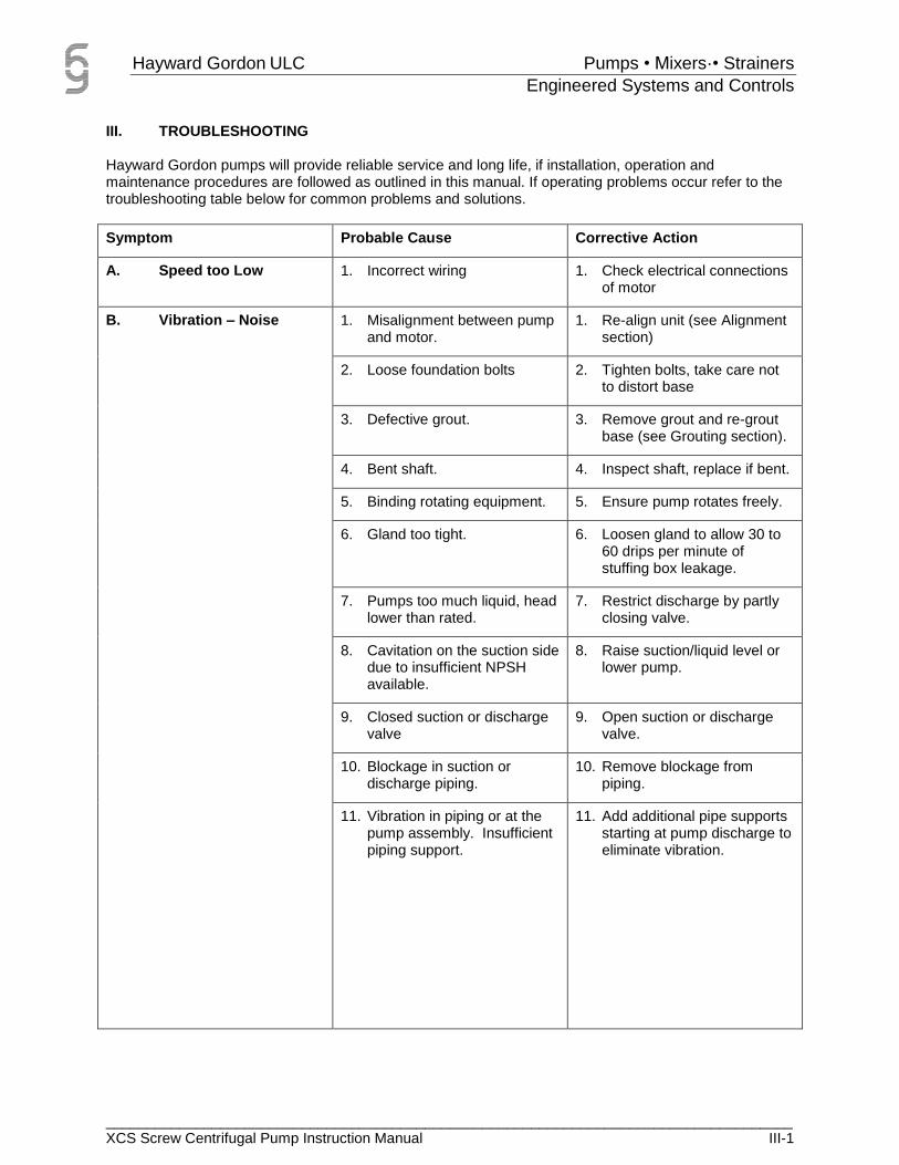
III. TROUBLESHOOTING Hayward Gordon pumps will provide reliable service and long life, if installation, operation and maintenance procedures are followed as outlined in this manual. If operating problems occur refer to the troubleshooting table below for common problems and solutions.
Symptom Probable Cause Corrective Action
A. Speed too Low 1. Incorrect wiring 1. Check electrical connections of motor
B. Vibration – Noise 1. Misalignment between pump and motor.
1. Re-align unit (see Alignment section)
2. Loose foundation bolts 2. Tighten bolts, take care not to distort base
3. Defective grout. 3. Remove grout and re-grout base (see Grouting section).
4. Bent shaft. 4. Inspect shaft, replace if bent.
5. Binding rotating equipment. 5. Ensure pump rotates freely.
6. Gland too tight. 6. Loosen gland to allow 30 to 60 drips per minute of stuffing box leakage.
7. Pumps too much liquid, head lower than rated.
7. Restrict discharge by partly closing valve.
8. Cavitation on the suction side due to insufficient NPSH available.
8. Raise suction/liquid level or lower pump.
9. Closed suction or discharge valve
9. Open suction or discharge valve.
10. Blockage in suction or discharge piping.
10. Remove blockage from piping.
11. Vibration in piping or at the pump assembly. Insufficient piping support.
11. Add additional pipe supports starting at pump discharge to eliminate vibration.

Hayward Gordon ULC Pumps • Mixers·• Strainers
Engineered Systems and Controls
____________________________________________________________________________________ XCS Screw Centrifugal Pump Instruction Manual III-2
Symptom Probable Cause Corrective Action
C. Overheating Bearings 1. Misalignment between pump and driver.
1. Realign unit (see Alignment)
2. Bent shaft. 2. Inspect shaft, replace if bent.
3. Binding rotating equipment. 3. Ensure pump rotates freely.
4. Excessive lubricant. 4. See Lubrication under the Maintenance section.
5. Defective or contaminated bearings
5. Clean bearing and lubricate, replace if worn.
D. Overheating Stuffing Box
1. Loss of sealing liquid to box. 1. Ensure liquid is reaching stuffing box
2. Excessive gland pressure 2. Loosen gland to allow 30 to 60 drips per minute of stuffing box leakage.
E. No Discharge Flow 1. Pump not primed. 1. Prime pump.
2. Speed too low. 2. Check voltage and frequency.
3. Required discharge head too high.
3. Reduce head or increase speed. Take care not to overload motor.
4. Suction lift higher than pump rating.
4. Raise suction/liquid level or lower pump.
5. Wrong rotation direction. 5. Reverse any 2 leads on 3-phase motor.

Hayward Gordon ULC Pumps • Mixers·• Strainers
Engineered Systems and Controls
____________________________________________________________________________________ XCS Screw Centrifugal Pump Instruction Manual III-3
Symptom Probable Cause Corrective Action
F. Not Enough Discharge Flow
1. Excessive air leaks in suction pipe or stuffing box.
1. Tighten all flange bolts. Supply stuffing box with liquid.
2. Speed too low. 2. Increase pumps speed.
3. Required discharge head too high.
3. Reduce head or increase speed. Take care not to overload motor.
4. Suction lift too high. 4. Raise suction/liquid level or lower pump.
5. Not enough suction head for hot or volatile liquids.
5. Raise suction/liquid level or lower pump.
6. Mechanical defects. 6. Replace defective parts.
7. Impeller damage. 7. Replace impeller.
8. Foot valve too small. 8. Use larger foot valve.
9. Not enough submergence of foot valve or suction opening.
9. Raise suction/liquid level. Lower foot valve or suction opening.
10. Wrong rotation direction. 10. Reverse any 2 leads on 3-phase motor.
11. Insufficient NPSH available. 11. Raise suction/liquid level or lower pump.

Hayward Gordon ULC Pumps • Mixers·• Strainers
Engineered Systems and Controls
____________________________________________________________________________________ XCS Screw Centrifugal Pump Instruction Manual III-4
Symptom Probable Cause Corrective Action
G. Not Enough Pressure 1. Speed too low 1. Provide proper voltage and frequency to motor. Increase pump speed; take care not to overload motor.
2. Too much air or gas in liquid. 2. Vent casing.
3. Damaged impeller. 3. Replace impeller.
4. Wrong rotation direction. 4. Reverse any 2 leads on 3-phase motor.
H. Loss of Prime 1. Leak in suction line. 1. Tighten suction line flange bolts.
2. Loss of sealing liquid to stuffing box.
2. Ensure sealing liquid reaches stuffing box.
3. Suction lift too high. 3. Raise suction/liquid level or lower pump.
4. Too much air or gas in liquid. 4. Vent case.
5. Defective casing gasket. 5. Replace gasket.
6. Insufficient NPSH available. 6. Raise suction level or lower pump.
I. High Power Consumption
1. Speed too high. 1. Lower pump speed.
2. Pumps too much liquid, head lower than rating
2. Restrict discharge by partly closing valve.
3. Specific gravity or viscosity of liquid pumped too high.
3. Reduce pump speed. Reduce liquid specific gravity or viscosity.
4. Bent shaft. 4. Inspect shaft, replace if bent.
5. Binding rotating element. 5. Ensure pump rotates freely.
6. Seal/packing gland too tight. 6. Loosen gland nuts.
J. Too Much Stuffing Box Leakage
1. Not enough gland pressure. 1. Tighten gland nuts.
2. Not enough packing in box. 2. Add additional ring of packing.
3. Grooved shaft sleeve. 3. Replace shaft sleeve.

Hayward Gordon ULC Pumps • Mixers·• Strainers
Engineered Systems and Controls
____________________________________________________________________________________ XCS Screw Centrifugal Pump Instruction Manual IV-1
IV. MAINTENANCE
A. Oil Lubricated Bearings
CAUTION! Oil lubricated powerframes are shipped without oil and must be filled before starting the pump. 1. Check nameplate (407) for pump model and refer to table for oil volume.
Table IV-1: Powerframe Oil Quantities
Powerframe Metric (L) US (us gal)
#1U 1.15 0.3
#2G/2F 1.4 0.4
#3G/3H 5.7 1.5
#4 9.0 2.4
2. Remove plug (709) and add oil into frame (207). Oil level must be maintained to the center of the sight glass as indicated on the label attached to the sight glass.
3. Install plug back into frame.
The pump should sit level within 3/8" per foot in longitudinal direction to ensure equal lubrication of both bearings. Use a contact type thermometer mounted on the powerframe or bearing housing to measure the bearing temperature. Do not "test" by hand as 120oF and higher may feel hot but bearing temperature up to 180oF are normal, depending on ambient conditions. Oil lubricated bearings may be safely operated up to at least 210oF. A sudden temperature increase indicates the possibility of damage that requires checking. Some recommended oil lubricants are:
Table IV-2: Recommended Oil Lubricants
Canada US
Esso Mineralube 20W-20 Exxon Faxam
Petro-Canada Harmony AW68 Gulf Harmony
Shell Tellus-68 Shell Tellus-68
Oil should contain rust inhibitor, antifoam and anti-oxidation additive. In normal continuous duty, change oil every 1500 hours to eliminate sludge accumulation. Increase the frequency of oil changes in hot, damp or corrosive atmospheres.

Hayward Gordon ULC Pumps • Mixers·• Strainers
Engineered Systems and Controls
____________________________________________________________________________________ XCS Screw Centrifugal Pump Instruction Manual IV-2
B. Grease Lubricated Bearings
All grease lubricated ball bearings are filled with grease at the factory and do not require filling before starting. Use a Mobilith SHC 220 (synthetic base NLGI Grade 2) grease to replenish the bearings every 2400 hours of continuous operation. Avoid over greasing the bearings. Grease lubricated bearings may be safely operated up to at least 180oF. Do not "test" by hand as 120oF and higher may feel hot to the touch. Higher temperatures may be experienced during the initial run-in period of approximately 36 operating hours. A sudden temperature increase indicates the possibility of damage that requires checking.
C. Packing
Standard die-molded packing is furnished in pump at time of shipment from factory. Use die-molded rings only.
(I) Repacking Stuffing Boxes
1. Remove nuts and gland.
2. Remove all packing rings and lantern ring with packing hook. Be sure to replace packing rings located on both sides of lantern ring.
3. Clean box, shaft and sleeve.
4. Install packing; see PACKING PROCEDURE (below).
Replace base ring with every second packing change. Frequent need to repack indicates deeply grooved shaft sleeve that should be replaced.
(II) PACKING PROCEDURE
1. Spin shaft by hand to see there is no binding.
2. Rub thin film of oil on shaft and in stuffing box.
3. Twist rings sideways to install die-molded packing. DO NOT pull rings straight out over shaft.
4. Insert needed number of rings, below lantern ring, staggering joints 90o and seating each ring individually.
5. Insert lantern ring, (should line up with tapped hole from seal connection).
6. Insert remaining packing rings, staggering joints 90o, and insert split gland.

Hayward Gordon ULC Pumps • Mixers·• Strainers
Engineered Systems and Controls
____________________________________________________________________________________ XCS Screw Centrifugal Pump Instruction Manual IV-3
(III) SETTING NEW PACKING
1. Using a wrench, tighten gland nuts snug, back off, and re-tighten finger tight.
2. Start pump (See Initial Starting).
3. Check Stuffing box for overheating. Shut down to cool, if necessary.
4. Gradually pull up gland by turning gland nuts alternately, one-quarter turn at a time, as packing wears from operation. Never tighten gland excessively.
5. An additional ring of packing may be added to box after gland has been taken up full travel. Repack stuffing box when packing gland has again been taken up full travel.
CAUTION!
With new packing, generous and steady initial leakage must be maintained. Over a period of four to six hours, the gland may be gradually tightened to achieve a stuffing box leakage rate of 30 to 60 drops a minute. Monitoring is recommended during this start up period to ensure that the lubrication is not cut off as the packing warms up and expands. If this occurs, the gland must be loosened to restore the leakage.
Turn sealing liquid on before pump is primed and leave it on as long as liquid is in pump. Use sealing fluid to prevent air leakage, if a prime is to be held when pump is stopped. Do not try to prevent air leakage by tightening gland unless definite measures are taken to be sure of re-adjustment before starting.
CAUTION!
The packing must not be allowed to run dry – even for short periods. Scoring of the shaft sleeve may result that will cause premature failure of the packing and will prevent proper sealing until a new sleeve is installed.
(IV) CAUSES OF PACKING FAILURE & EXCESSIVE LEAKAGE
1. Packing not properly installed.
2. Packing not suitable for pressure and temperature.
3. Packing subject to attack by liquid pumped.
4. Inner rings not seated properly, outer rings carrying entire load.
5. Foreign matter (dirt) in stuffing box causing rapid scoring of shaft sleeve.
Keep sets of proper packing on hand.

Hayward Gordon ULC Pumps • Mixers·• Strainers
Engineered Systems and Controls
____________________________________________________________________________________ XCS Screw Centrifugal Pump Instruction Manual IV-4
D. Mechanical Seal
See Manufacturer's drawing and instructions for maintenance and lubrication requirements. Causes of failures and leakage between seal faces:
1. Scored or worn seal faces.
2. Gland bolted up unevenly.
3. Stationary insert face not perpendicular to shaft axis.
4. Binding seal ring.
5. Wobbling rotating seal ring.
6. Cracked or broken stationary insert.
7. Shaft run out through stuffing box.
8. Foreign matter between seal faces.
9. Loose or released set screws.
10. Spring compression lost.
11. Mechanical seal improperly applied or installed.
12. Improper materials of construction for the environment and/or temperature.
13. Differential or system pressure too high for seal.
Keep a spare seal on hand if stand-by equipment is not available.
E. Drive
See Manufacturer’s Instructions.
F. Motor
See Manufacturer’s Instructions.

Hayward Gordon ULC Pumps • Mixers·• Strainers
Engineered Systems and Controls
____________________________________________________________________________________ XCS Screw Centrifugal Pump Instruction Manual IV-5
G. Preventative Maintenance Schedule
Component Maintenance Activity Frequency Amount & Type of Lubricant
Reference
Oil Lubricated Bearings
1. Add oil into powerframe before starting the pump.
Initial Powerframe 1U: 1.15 L / 0.3 US gal Powerframe 2G/2F: 1.4L / 0.4 US gal Powerframe 3G/3H: 5.7L / 1.5 US gal Powerframe 4: 9.0L / 2.4 US gal
Table IV-3: Powerframe Oil
Quantities
2. Change oil. Every 1500 hours
Canada:
Esso Mineralube 20W-20
Petro-Canada Harmony AW68
Shell Tellus-68
US:
Exxon Faxam
Gulf Harmony
Shell Tellus 68
Table IV-4: Recommended Oil Lubricants
Grease Lubricated Bearings
3. Replenish grease to bearings
Every 2400 hours of continuous operation
Mobilith SHC 220 (synthetic NLGI Grade 2)
O&M Manual, Section IV
Packing 4. Replace base ring With every 2nd packing change
n/a O&M Manual, Section IV
Mechanical Seal
5. Monitor for possible leakage between seal faces. Replace as necessary.
Weekly N/A O&M Manual Section IV
6. Also any maintenance as identified by Manufacturer for specific model
TBD N/A Manufacturer’s datasheets
Direct Drive 7. Inspect alignment and for signs of wear
Semi-annually N/A Manufacturer’s Instruction Manual

Hayward Gordon ULC Pumps • Mixers·• Strainers
Engineered Systems and Controls
____________________________________________________________________________________ XCS Screw Centrifugal Pump Instruction Manual IV-6
Component Maintenance Activity Frequency Amount & Type of Lubricant
Reference
V Belt 8. Inspect parts.
Inspection while running (check for noise, vibration)
Inspect sheaves alignment
Check belt fit
Keep belts clean
Use belt guards
Check for hot bearings
Maintain proper belt tension
Semi-annually N/A Manufacturer’s Instruction Manual (Wood’s)
Motor 9. Inspect parts.
Check the motor periodically.
Keep the motor clean and assure free air flow.
Check the seals for V Ring and replace, if required.
Check the connections as well as supporting screws.
Check the bearings and observe: any excessive noise, bearing temperature and grease condition.
When a changing, under normal conditions, is detected, check the motor and replace the required parts. The frequency of the inspections depends on them motor type and on the application conditions.
Semi-annually N/A WEG Instruction Manual

Hayward Gordon ULC Pumps • Mixers·• Strainers
Engineered Systems and Controls
____________________________________________________________________________________ XCS Screw Centrifugal Pump Instruction Manual IV-7
Component Maintenance Activity Frequency Amount & Type of Lubricant
Reference
Motor 10. Inspect parts. Semi-annually N/A Teco-Westinghouse Installation & Maintenance Instructions
11. Lubricate
Frame 143T-256T: Double shielded and pre-lubricated ball-bearing motors without grease fittings and don t need re-lubrication, except on MAX-E1¤ and MAX-E2¤ products which have re-greasable features.
Frames 280TS, 320-449TZ(TS): Motors having grease fittings and grease discharge devices at brackets. Motors are shipped with grease for initial running. It is necessary to relubricate anti-friction bearing motors periodically, depending on size and type of service. See Table 2 to provide maximum bearing life. Excessive or too frequent lubrication may damage the motor.
Be sure fittings are clean and free from dirt. Using a low-pressure grease gun, pump in the recommended grease until new grease appears at grease discharge hole.
If re-lubrication is to be performed with the motor running, stay clear of rotating parts. After re-greasing, allow the motor to run for ten to thirty minutes.
See Table 2 of Teco-Westinghouse Installation and Maintenance Instruction
ALVANIA R3 grease or equivalent lithium based grease unless special grease is specified on the nameplate.
Hayward Gordon ULC Pumps • Mixers·• Strainers
Engineered Systems and Controls
____________________________________________________________________________________ XCS Screw Centrifugal Pump Instruction Manual V-1
V. SERVICE & REPAIR
A. Disassembly of Pump
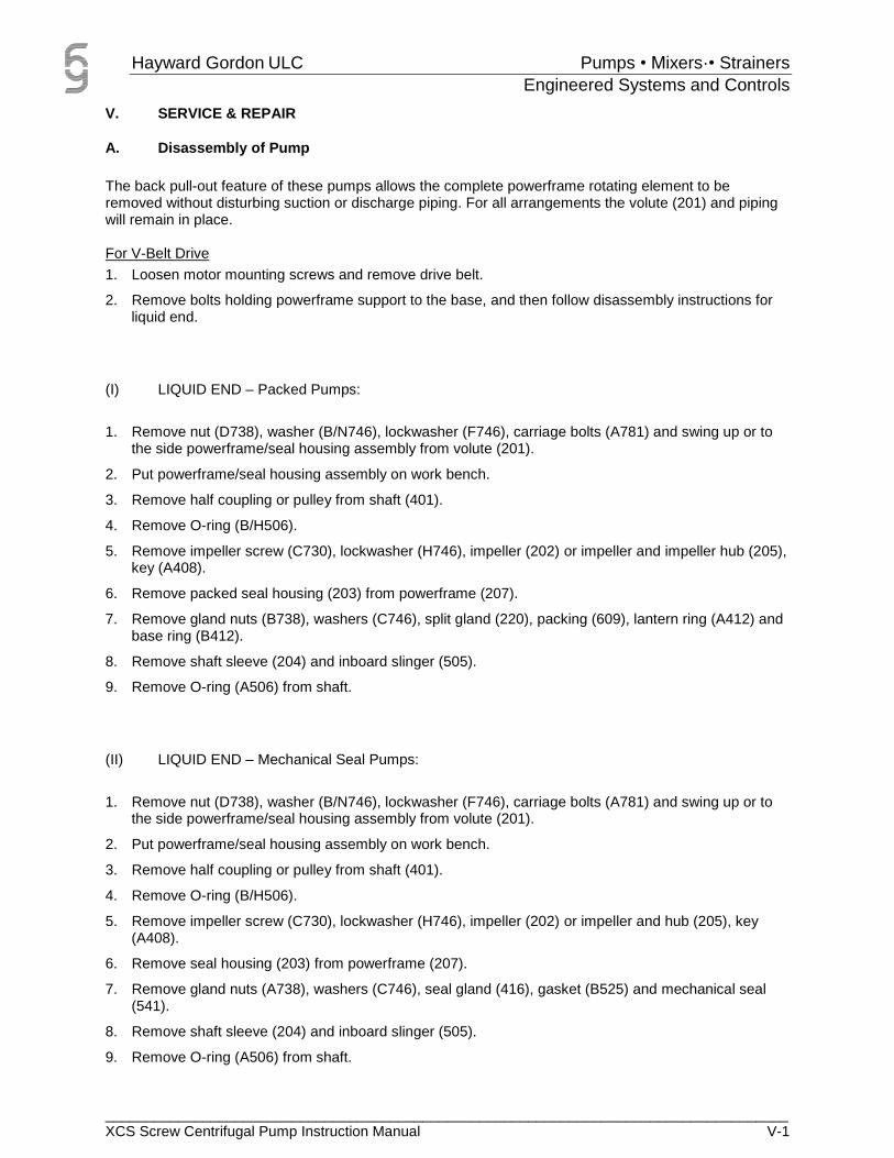
The back pull-out feature of these pumps allows the complete powerframe rotating element to be removed without disturbing suction or discharge piping. For all arrangements the volute (201) and piping will remain in place. For V-Belt Drive
1. Loosen motor mounting screws and remove drive belt.
2. Remove bolts holding powerframe support to the base, and then follow disassembly instructions for liquid end.
(I) LIQUID END – Packed Pumps:
1. Remove nut (D738), washer (B/N746), lockwasher (F746), carriage bolts (A781) and swing up or to the side powerframe/seal housing assembly from volute (201).
2. Put powerframe/seal housing assembly on work bench.
3. Remove half coupling or pulley from shaft (401).
4. Remove O-ring (B/H506).
5. Remove impeller screw (C730), lockwasher (H746), impeller (202) or impeller and impeller hub (205), key (A408).
6. Remove packed seal housing (203) from powerframe (207).
7. Remove gland nuts (B738), washers (C746), split gland (220), packing (609), lantern ring (A412) and base ring (B412).
8. Remove shaft sleeve (204) and inboard slinger (505).
9. Remove O-ring (A506) from shaft.
(II) LIQUID END – Mechanical Seal Pumps:
1. Remove nut (D738), washer (B/N746), lockwasher (F746), carriage bolts (A781) and swing up or to the side powerframe/seal housing assembly from volute (201).
2. Put powerframe/seal housing assembly on work bench.
3. Remove half coupling or pulley from shaft (401).
4. Remove O-ring (B/H506).
5. Remove impeller screw (C730), lockwasher (H746), impeller (202) or impeller and hub (205), key (A408).
6. Remove seal housing (203) from powerframe (207).
7. Remove gland nuts (A738), washers (C746), seal gland (416), gasket (B525) and mechanical seal (541).
8. Remove shaft sleeve (204) and inboard slinger (505).
9. Remove O-ring (A506) from shaft.
Hayward Gordon ULC Pumps • Mixers·• Strainers
Engineered Systems and Controls
____________________________________________________________________________________ XCS Screw Centrifugal Pump Instruction Manual V-2
(III) POWERFRAME – Oil
For Powerframe #1, 2
1. Drain oil from powerframe by removing plug (B705).
2. Remove cap screws (A730), lockwashers (M746) and press shaft/bearing assembly from powerframe (207) and remove shims (A451).
3. Remove inboard retaining ring (A504) and press inboard bearing (A501) from shaft.
4. Remove retaining ring (B504) from bearing housing (211) and slide bearing housing off outboard bearing(s) (B501).
5. Remove outboard lip seal (B503) and O-ring (E506) from bearing housing.
6. Remove bearing nut (520) and lock washer (521).
7. Press outboard bearing(s) from shaft.
8. Remove lip seal (A503) from frame (207).
For Powerframe #3, 4
1. Drain oil from powerframe by removing plug (B705).
2. Remove cap screws (A730), lockwashers (M746) and press shaft/bearing assembly from powerframe (207) and remove shims (A451).
3. Remove inboard retaining ring (504) and press inboard bearing (A501) from shaft.
4. Remove cap screws (B730), lockwashers (D746) and slide outboard bearing cap (210) from shaft.
5. Remove outboard lip seal (B503) from bearing cap.
6. Remove both O-rings (E506) and (F506) from bearing housing (211).
7. Slide bearing housing (211) off outboard bearing (B501).
8. Remove bearing nut (520) and lock washer (521).
9. Press outboard bearing from shaft.
10. Remove inboard seal plate (D410) from frame. Remove O-ring (G506) and lip seal (A503) from inboard seal plate.

Hayward Gordon ULC Pumps • Mixers·• Strainers
Engineered Systems and Controls
____________________________________________________________________________________ XCS Screw Centrifugal Pump Instruction Manual V-3
(IV) POWERFRAME – Grease
For Powerframe #1, 2
1. Remove cap screws (A730), lockwashers (M746) and press shaft/bearing assembly from powerframe (207) and remove shims (A451).
2. Remove inboard retaining ring (A504); press inboard bearing (A501) and grease shield (A410) from shaft.
3. Remove round head screws (726) and outboard grease shield (B410).
4. Remove outboard retaining ring (B504) from bearing housing (211) and slide bearing housing off outboard bearing(s) (B501).
5. Remove outboard lip seal (B503) and O-ring (E506) from bearing housing.
6. Remove bearing nut (520) and lock washer (521).
7. Press outboard bearing(s) from shaft.
8. Remove inboard lip seal (A503) from powerframe.
For Powerframe #3, 4
1. Remove cap screws (A730), lockwashers (M746) and press shaft/bearing assembly from powerframe (207) and remove shims (A451).
2. Remove retaining ring (504), press inboard bearing (A501) and inboard grease shield (A410) from shaft.
3. Remove cap screws (B730), lockwashers (D746) and slide outboard bearing cap (210) from shaft.
4. Remove lip seal (B503) from bearing cap.
5. Remove both O-rings (E506) and (F506) from bearing housing (211).
6. Slide bearing housing (211) off outboard bearing (B501).
7. Remove bearing nut (520) and lock washer (521).
8. Press outboard bearing together with outboard grease shield (B410) from shaft.
9. Remove inboard seal plate (D410) from frame. Remove O-ring (G506) and lip seal (A503) from inboard seal plate.

Hayward Gordon ULC Pumps • Mixers·• Strainers
Engineered Systems and Controls
____________________________________________________________________________________ XCS Screw Centrifugal Pump Instruction Manual V-4
B. Parts Inspection
Ball Bearings: Replace if damaged. If they are dirty, flush with clean kerosene or carbon tetrachloride, dry and coat with machine oil. Protect until ready for use. Lip Seal: Inspect and replace if worn or damaged. Lip seal is held by press fit in bearing housing or bearing cap and frame. Shaft: Check for bent shaft. Bearing and lip seal seats must be in perfect condition. Replace if necessary. Shaft Sleeves: Sleeve surface in stuffing box must be smooth and free of grooves. Replace if grooved. Impeller: If the impeller shows excessive wear due to abrasion or corrosion and performance cannot be restored, it must be replaced. Packing: Replace if worn or damaged. Mechanical Seal: Replace if worn or damaged. All parts must be clean before reassembly. This is especially important at retaining ring grooves, threads, gasket surfaces and bearing lubrication areas. Remove burrs with fine emery cloth especially on shaft surface.
C. Reassembly of Pump
All bolts used on dynamically loaded components i.e., pump impellers MUST be tightened to the torque values shown below. Over tightening may cause premature fatigue failure. Figures are based on dry (non-lubricated) bolts.
Table V-1: Recommended Bolt Torque Values
Recommended Tightening Torque All Values in ft./lbs.
Bolt Diameter (in.)
Std. bolts grades 0-3 Stainless Steel
Alloy 20 & Hastelloy B & C
Grades 5-8 All socket head capscrews
3/8” 25 36
1/2” 55 85
5/8” 95 165
3/4” 165 275
7/8” 190 470
1” 260 700
1 ¼” 525 1200

Hayward Gordon ULC Pumps • Mixers·• Strainers
Engineered Systems and Controls
____________________________________________________________________________________ XCS Screw Centrifugal Pump Instruction Manual V-5
(I) POWERFRAME – Oil
For Powerframe #1, 2
1. Install lip seal (A503) into frame (207).
2. Press outboard bearing(s) (B501) on shaft.
3. Install lock washer (521) and bearing nut (520).
4. Install outboard lip seal (B503) and O-ring (E506) into bearing housing (211). Lightly grease the O-ring.
5. Lightly grease shaft in places where lip seals (B503) and (A503) will be engaged.
6. Install bearing housing over outboard bearing(s) and place retaining ring (B504).
7. Place inboard bearing (A501) on shaft and install inboard retaining ring (A504) onto shaft.
8. Slide complete shaft assembly into powerframe.
9. Install cap screws (A730) with lockwashers (M746).
10. Fill powerframe with oil. Refer to MAINTENANCE for the quantity and type of oil to be used.
For Powerframe #3, 4
1. Place lip seal (A503) into and O-ring (G506) around inboard lip seal plate (D410). Install seal plate into frame (207) using seal compound.
2. Press outboard bearing (B501) on shaft.
3. Install lock washer (521) and bearing nut (520).
4. Install bearing housing (211) over outboard bearing.
5. Install O-ring (F506) in bearing housing (211).
6. Install outboard lip seal (B503) into bearing cap (210).
7. Bolt bearing cap to bearing housing using socket head cap screws (B730) with lockwashers (D746).
8. Place inboard bearing (A501) on shaft and install inboard retaining ring (504) onto shaft.
9. Install O-ring (E506) on bearing housing and lightly grease O-ring.
10. Lightly grease shaft in places where lip seals (B503) and (A503) will be engaged.
11. Slide complete shaft assembly into powerframe.
12. Install cap screws (A730) with lockwashers (M746)
13. Fill powerframe with oil. Refer to MAINTENANCE for the quantity and type of oil to be used.

Hayward Gordon ULC Pumps • Mixers·• Strainers
Engineered Systems and Controls
____________________________________________________________________________________ XCS Screw Centrifugal Pump Instruction Manual V-6
(II) POWERFRAME – Grease
For Powerframe #1, 2
1. Install lip seal (A503) into frame (207).
2. Pack bearings with grease. Forcing grease through the bearing from the large end to the small end will ensure proper distribution. Alternatively a commercially available mechanical seal packer can be used. Refer to Grease Lubricated Bearings, for the type of grease to be used.
3. Press outboard bearing(s) (B501) on shaft.
4. Install lock washer (521) and bearing nut (520).
5. Install outboard lip seal (B503) and O-ring (E506) into bearing housing (211). Lightly grease the O-ring.
6. Lightly grease shaft in places where lip seals (B503) and (A503) will be engaged.
7. Install bearing housing over outboard bearing(s) and place retaining ring (B504).
8. Install outboard grease shield (B410) and round head screws (726).
9. Place inboard grease shield (A410) on shaft; press inboard bearing (A501) and install retaining ring (A504) onto shaft.
10. Slide complete shaft assembly into powerframe.
11. Install cap screws (A730) with lockwashers (M746).
For Powerframe #3, 4
1. Place lip seal (A503) into and O-ring (G506) around inboard lip seal plate (D410). Install seal plate into frame (207) using seal compound.
2. Install outboard grease shield (B410) on shaft (401).
3. Pack bearings with grease. For taper roller bearings, it is important that grease is carefully packed into the bearings so that it can get between the rollers and case. Forcing grease through the bearing from the large end to the small end will ensure proper distribution. Alternatively a commercially available mechanical grease packer can be used. Refer to MAINTENANCE, for the type of grease to be used.
4. Press outboard bearing (B501) on shaft.
5. Install lock washer (521) and bearing nut (520).
6. Install bearing housing (211) over outboard bearing.
7. Install O-ring (F506) in bearing housing (211).
8. Install lip seal (B503) into bearing cap (210).
9. Lightly grease shaft in places where lip seals (B503) and (A503) will be engaged.
10. Bolt bearing cap to bearing housing using socket head cap screws (B730) and lockwashers (D746).
11. Install O-ring (E506) on bearing housing and lightly grease O-ring.
12. Install inboard grease shield (A410) on shaft; press inboard bearing (A501) on shaft with shield facing bearing (B501) and install retaining ring (504) onto shaft.
13. Slide complete shaft assembly into powerframe.
14. Install cap screws (A730) with lockwashers (M746).
Hayward Gordon ULC Pumps • Mixers·• Strainers
Engineered Systems and Controls
____________________________________________________________________________________ XCS Screw Centrifugal Pump Instruction Manual V-7
(III) LIQUID END – Packed Pumps
1. Install O-ring (A506) on shaft (401).
2. Install sleeve (204) on shaft making sure groove in sleeve line up with keyway in shaft. Slide slinger (505) on shaft sleeve.
3. Install base ring (B412), packing (609) and lantern ring (A412) in seal housing (203).
4. Install split gland (220).
5. Install gland washers (C746) and gland nuts (B738) finger tight.
6. Slide packed seal housing (203) onto shaft sleeve ensuring that seal housing locates in spigot in powerframe (207).
7. Install key (A408) in shaft keyway, ensuring that one end of key goes into shaft sleeve groove.
8. Install impeller (202) or impeller hub (205) and impeller, lockwasher (H746) and impeller screw (C730). Tighten impeller screw and then try to rotate impeller by hand.
9. Loosen bearing housing cap screws (A730) and using set screws (732) move shaft rotating assembly until back of the impeller presses lightly against seal housing.
10. Install O-ring (B/H506).
11. Install powerframe/seal housing assembly into volute (201) and attach with carriage bolts (A781), washers (B/N746), lockwashers (F746) and nuts (D738).
(IV) LIQUID END – Mechanical Seal Pumps
1. Install O-ring (A506) on shaft (401).
2. Install sleeve (204) on shaft making sure groove in sleeve lines up with keyway in shaft. Slide slinger (505) on shaft sleeve.
3. Place seal gland (416) and gasket (B525) on shaft.
4. Install mechanical seal (541) according to seal drawing and instruction.
5. Slide seal housing (203) over mechanical seal.
6. Slide seal gland over studs (A735), install gland washers (C746) and gland nuts (A738) finger tight.
7. Install key (A408) in shaft keyway ensuring that one end of key goes into shaft sleeve groove.
8. Install impeller (202) or impeller hub (205) and impeller, lockwasher (H746) and impeller screw (C730). Tighten impeller screw and try to rotate impeller by hand.
9. Loosen bearing housing cap screws (A730) and using set screws (732) move shaft rotating assembly until back of the impeller presses lightly against seal housing.
10. Install O-ring (B/H506).
11. Install powerframe/seal housing assembly over volute (201) and attach with carriage bolts (A781), washers (B/N746), lockwashers (F746) and nuts (D738).

Hayward Gordon ULC Pumps • Mixers·• Strainers
Engineered Systems and Controls
____________________________________________________________________________________ XCS Screw Centrifugal Pump Instruction Manual V-8
(V) SPLIT SEALS
Many split seals are provided with solid faces from the factory. This is done to ease the process of installation by the manufacturer and to extend your seal life. All other major seal components are radially split. In the event you need to change out the seal faces, you will need to fracture the installed solid faces and remove them. Be careful not to damage the shaft or shaft sleeve. Once the original seal has been removed, you can use the seal installation instructions that were packed with your replacement seal. Your new seal faces will be split. This allows you to perform a complete seal replacement without any equipment disassembly.
Figure V-1: Split Seal - SOLID FACES
(a) Chesterton 442 - Acceptable Leak Rate Specifications
In applications using 442 split seals, it is not unusual to have some leakage at start-up. The following table should be used as a guide to judge seal installation and operation.
Seal Size (inches) Run in Leakage (Drops / Minute)
Run in Duration Operational Leakage (Drops / Minute)
1.5 – 2.5 <60 72 hours <40
2.625 – 4.75 <90 144 hours <60
4.875 – 7.75 <120 216 hours <80
>7.75 <150 288 hours <80
Please note that split mechanical seals which initially have zero leakage may exhibit minute leakage due to operational disturbances.

Hayward Gordon ULC Pumps • Mixers·• Strainers
Engineered Systems and Controls
____________________________________________________________________________________ XCS Screw Centrifugal Pump Instruction Manual V-9
(VI) IMPELLER CLEARANCES
(a) Pumps with Suction Cone and No Liner
(1) To adjust Impeller/Seal Housing Back Clearance:
1. Loosen screws (A730). Using set screws (A732) as jacking screws, move bearing housing (211) out of powerframe (207) until impeller (202) or impeller hub (205) touches the seal housing (203). Check by rotating shaft by hand.
2. Measure gap between bearing housing and frame.
3. Install shims – their total thickness should be .010" to .020" less than the measured gap.
4. Loosen set screws (A732) and tighten screws (A730) and check rotating shaft by hand.
(2) To adjust Impeller/Suction Cone Front Clearance:
1. Verify clearance “G” with feeler gauge.
2. Use shim set (B451) to obtain clearance “G”. To install shim set, loosen bolts (A781) holding suction cone (214) only.
3. Pull out suction cone, use feeler gauge to check and obtain required clearance “G” between impeller and suction cone.
4. Measure gap between suction cone and volute (201) clamping face. Thickness of shim set required is equal to this gap.
5. Install required shim set.
6. Tighten bolts (A781).
7. Try rotating shaft by hand, it should rotate freely.
Recheck the clearances. Repeat as necessary.

Hayward Gordon ULC Pumps • Mixers·• Strainers
Engineered Systems and Controls
____________________________________________________________________________________ XCS Screw Centrifugal Pump Instruction Manual V-10
(b) Pumps with Suction Cone and Adjustable Liner
(1) To adjust Impeller/Seal Housing Back Clearance:
1. Loosen screws (A730). Using set screws (A732) as jacking screws, move bearing housing (211) out of powerframe (207) until impeller (202) or impeller hub (205) touches the seal housing (203). Check by rotating shaft by hand.
2. Measure gap between bearing housing and frame.
3. Install shims – their total thickness should be .010" to .020" less than the measured gap.
4. Loosen set screws (A732) and tighten screws (A730) and check rotating shaft by hand.
(2) To adjust Impeller/Suction Liner Front Clearance:
Front clearance between replaceable suction liner and impeller can be externally adjusted. Units with the adjustable feature will have three regulating screws on the front of the suction cone. To adjust the clearance:
1. Loosen the hex nuts (E738) on each adjustable liner screw.
2. Carefully screw in each adjustable screw (C410) until the impeller touches the cone (shaft cannot turn) being sure to adjust each screw the same amount.
3. Back off each of the adjustable screws by the amount specified in Table V-2: Impeller Clearances
4. Tighten the hex nuts ensuring the adjustable screws stay stationary.
5. Rotate the shaft by hand to check for rubbing.
6. Using a feeler gauge, check between the impeller and liner for the specified clearance “G”.
Recheck the clearance. Repeat as necessary. Additional shim set (B451) may be required to obtain clearance “G”.
1. To install shim set, loosen bolts holding suction cone (B214) only.
2. Repeat procedure 1-6 as outlined above.
3. Measure gap between suction cone and volute (201) clamping face. Thickness of shim set (B451) required is equal to this gap.
4. Install required shim set.
5. Tighten bolts (A781).
Recheck the clearance. Repeat as necessary.

Hayward Gordon ULC Pumps • Mixers·• Strainers
Engineered Systems and Controls
____________________________________________________________________________________ XCS Screw Centrifugal Pump Instruction Manual V-11
Table V-2: Impeller Clearances
Pump Model Minimum Front
Impeller Clearance “G”
Back Impeller Clearance “H”
# of Turns of Screw C410
XCS 4A/B/CMC 0.015”- 0.020” 0.010”- 0.015” 3/8
XCS 4HA/HB 0.020”- 0.025” 0.010”- 0.015” 1/2
XCS 5A/B/C 0.020”- 0.025” 0.010”- 0.015” 1/2
XCS 5HA/HC 0.020”- 0.025” 0.010”- 0.015” 3/8
XCS 6A/B/D 0.020”- 0.025” 0.010”- 0.015” 1/2
XCS 8C/D 0.020”- 0.025” 0.010”- 0.015” 1/2
XCS 10B/C 0.025”- 0.030” 0.010”- 0.015” 3/4
XCS 12B/C 0.025”- 0.030” 0.010”- 0.015” 3/4
XCS 16C 0.030”- 0.035” 0.015”- 0.020” 3/4
Figure V-2: Impeller Clearances

Hayward Gordon ULC Pumps • Mixers·• Strainers
Engineered Systems and Controls
____________________________________________________________________________________ XCS Screw Centrifugal Pump Instruction Manual V-12
D. Parts Inventory Guide
For parts inventory refer to General Assembly drawing and parts lists. The recommended spare parts are:
Table V-3: Recommended Spare Parts
Item Description
204 Shaft Sleeve
202 Impeller (*L)
214 Suction Cone (*L)
A214 Suction Liner (*L)
A412 Lantern Ring (*P)
B412 Base Ring (*P)
A501 Inboard Bearing
B501 Outboard Bearing
A503 Inboard Lip Seal
B503 Outboard Lip Seal
A506 O-ring Shaft Sleeve
B506 O-ring Volute Casting
C506 O-ring Liner (flange side)
D506 O-ring Liner (casing side)
E506 O-ring Bearing Housing
F506 O-ring Bearing Cap
G506 O-ring Lip Seal Plate (# 3G, 3H & 4 frames)
H506 O-ring Stuffing Box (# 3H & 4 frames)
A525 Volute Casing Gasket (XCS-5, -8 only)
B525 Seal Gland Gasket (*M)
541 Mechanical Seal Assembly (*M)
609 Packing Rings (*P)
(*L) = Long Term Spares (*M) = Mechanical Sealed Pumps (*P) = Packed Pumps

Hayward Gordon ULC Pumps • Mixers·• Strainers
Engineered Systems and Controls
____________________________________________________________________________________ XCS Screw Centrifugal Pump Instruction Manual V-13
E. Parts Ordering
The following information should be available for prompt processing of parts orders:
1. The serial number of the pump (on nameplate)
2. The part name (on sectional drawing)
3. The part number (on sectional drawing)
4. The quantity of parts needed
Hayward Gordon ULC may supply an interchangeable part that is not identical in appearance or symbol. This is done only if the part has been improved. Examine parts carefully upon their receipt. If motor or motor parts are ordered, specify name of drive manufacturer and all other data on driver nameplate.

Hayward Gordon ULC Pumps • Mixers·• Strainers
Engineered Systems and Controls
____________________________________________________________________________________ XCS Screw Centrifugal Pump Instruction Manual VI-1
VI. DRAWINGS See following pages for general assembly drawings and parts lists.