
Hawaii Dairy Farm (HDF) Mahaulepu - Kauai Hawaii Overview...
100
Hawaii Dairy Farm (HDF) Mahaulepu - Kauai Hawaii Overview Hawaii Dairy Farms is being designed for 2000 milking cows. Core stock (880 cows) will be imported from Missouri-USA. During the first years of operation, the cows get 70% of their diet from grazing pasture (Kikuyu) in paddocks and 30% grains (in-shed feeding during 8-10 minute milking). The target is to lift the percentage of Kikuyu up-to 85% as the soil and pasture management improves in the next years. The 2000 cows will be managed in small groups (300-330 cows mob) and are milked twice a day. The cows spend 22 hours in the paddock with only 2 hours in the milking area (1 hour per milking) every day. Only one mob can be held in the dairy at any one time. HEAVY USE AREA PROTECTION All the areas that are used by livestock, people, farm machinery and other vehicles, will be designed to provide a stable, non-eroding surface. Crushed stone will be used as base course to upgrade all sites that need increased load bearing strength, drainage, separation of material and soil reinforcement. The base course will be compacted, smoothed, and rolled before surfacing is applied. All surfacing materials will be placed and finished to the lines and grades shown on the construction drawings. All grading, levelling and smoothing will be completed according to the drawings, prior to start of surfacing operations. The subgrade will be compacted to a firm foundation for the surfacing materials. Access Road An existing road in place will be upgraded to meet farm traffic needs. A gravel parking area (200sq mtr or 2153 sq ft) will be reserved to park the vehicles off the road. The total length of the access road is 1.5km from the main road to the milking shed and parking area. The roadbed width of the road is 15.5 ft (4.7m) which includes a trade-width of 11.48 ft (3.5m) and shoulder width of or 4 feet (1.2m), 2 feet on each side. The grade (gradient) of the access road will be less than 10 %. A ramp will be constructed to get access to the milking shed. (refer to construction drawings and cross section)
Transcript of Hawaii Dairy Farm (HDF) Mahaulepu - Kauai Hawaii Overview...
Hawaii Dairy Farm (HDF) Mahaulepu - Kauai Hawaii Overview Hawaii Dairy Farms is being designed for 2000 milking cows. Core stock (880 cows) will be imported from Missouri-USA. During the first years of operation, the cows get 70% of their diet from grazing pasture (Kikuyu) in paddocks and 30% grains (in-shed feeding during 8-10 minute milking). The target is to lift the percentage of Kikuyu up-to 85% as the soil and pasture management improves in the next years. The 2000 cows will be managed in small groups (300-330 cows mob) and are milked twice a day. The cows spend 22 hours in the paddock with only 2 hours in the milking area (1 hour per milking) every day. Only one mob can be held in the dairy at any one time.
HEAVY USE AREA PROTECTION All the areas that are used by livestock, people, farm machinery and other vehicles, will be designed to provide a stable, non-eroding surface. Crushed stone will be used as base course to upgrade all sites that need increased load bearing strength, drainage, separation of material and soil reinforcement. The base course will be compacted, smoothed, and rolled before surfacing is applied. All surfacing materials will be placed and finished to the lines and grades shown on the construction drawings. All grading, levelling and smoothing will be completed according to the drawings, prior to start of surfacing operations. The subgrade will be compacted to a firm foundation for the surfacing materials.
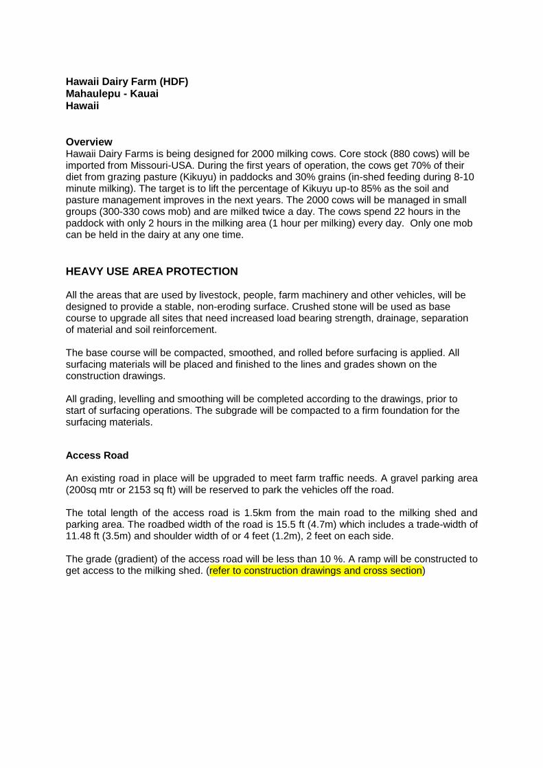
Access Road
An existing road in place will be upgraded to meet farm traffic needs. A gravel parking area (200sq mtr or 2153 sq ft) will be reserved to park the vehicles off the road. The total length of the access road is 1.5km from the main road to the milking shed and parking area. The roadbed width of the road is 15.5 ft (4.7m) which includes a trade-width of 11.48 ft (3.5m) and shoulder width of or 4 feet (1.2m), 2 feet on each side. The grade (gradient) of the access road will be less than 10 %. A ramp will be constructed to get access to the milking shed. (refer to construction drawings and cross section)
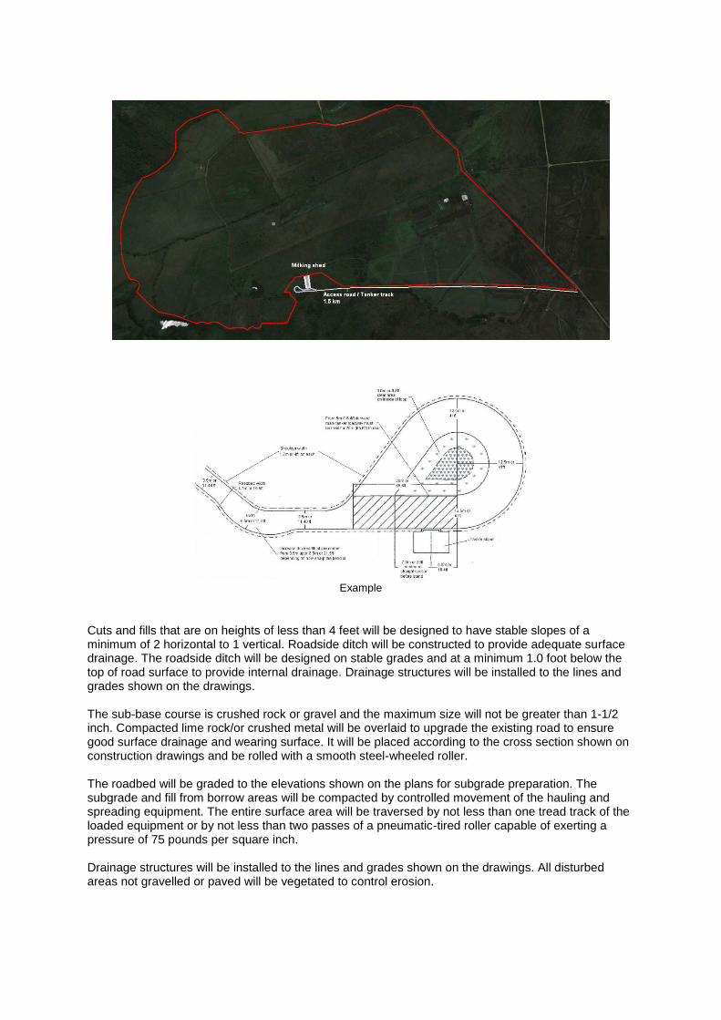
Example
Cuts and fills that are on heights of less than 4 feet will be designed to have stable slopes of a minimum of 2 horizontal to 1 vertical. Roadside ditch will be constructed to provide adequate surface drainage. The roadside ditch will be designed on stable grades and at a minimum 1.0 foot below the top of road surface to provide internal drainage. Drainage structures will be installed to the lines and grades shown on the drawings. The sub-base course is crushed rock or gravel and the maximum size will not be greater than 1-1/2 inch. Compacted lime rock/or crushed metal will be overlaid to upgrade the existing road to ensure good surface drainage and wearing surface. It will be placed according to the cross section shown on construction drawings and be rolled with a smooth steel-wheeled roller. The roadbed will be graded to the elevations shown on the plans for subgrade preparation. The subgrade and fill from borrow areas will be compacted by controlled movement of the hauling and spreading equipment. The entire surface area will be traversed by not less than one tread track of the loaded equipment or by not less than two passes of a pneumatic-tired roller capable of exerting a pressure of 75 pounds per square inch. Drainage structures will be installed to the lines and grades shown on the drawings. All disturbed areas not gravelled or paved will be vegetated to control erosion.
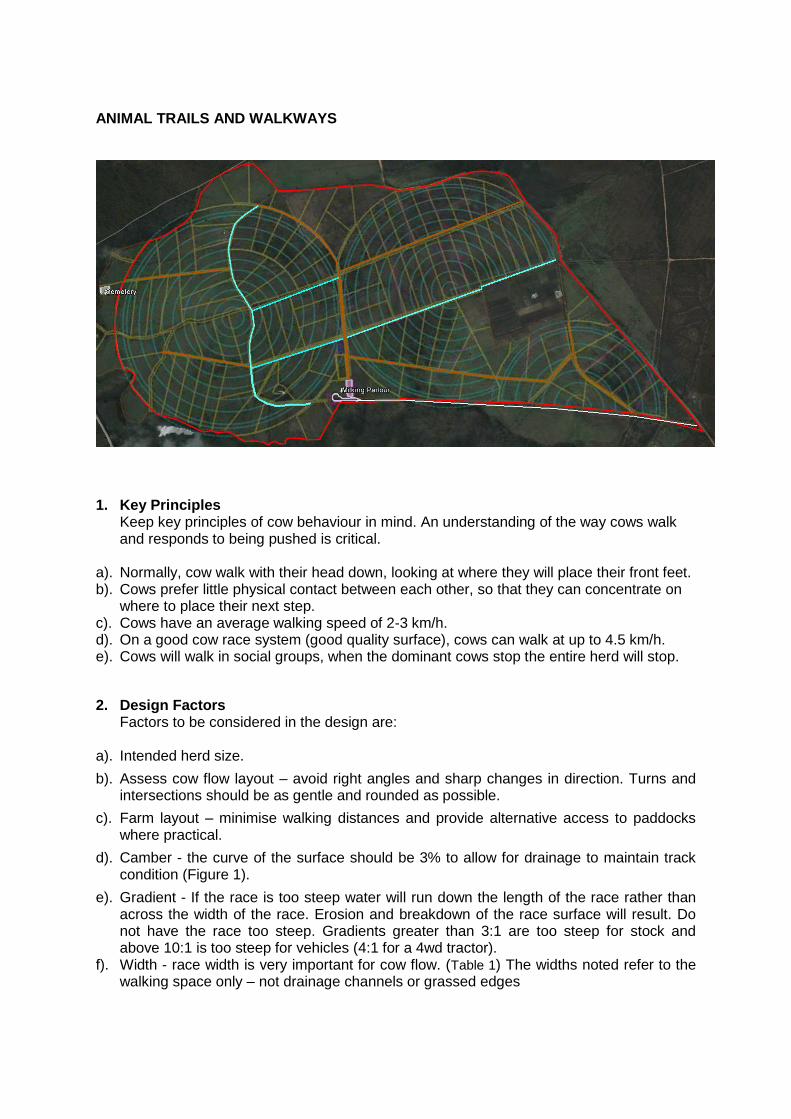
ANIMAL TRAILS AND WALKWAYS
1. Key Principles Keep key principles of cow behaviour in mind. An understanding of the way cows walk and responds to being pushed is critical.
a). Normally, cow walk with their head down, looking at where they will place their front feet. b). Cows prefer little physical contact between each other, so that they can concentrate on
where to place their next step. c). Cows have an average walking speed of 2-3 km/h. d). On a good cow race system (good quality surface), cows can walk at up to 4.5 km/h. e). Cows will walk in social groups, when the dominant cows stop the entire herd will stop.
2. Design Factors Factors to be considered in the design are:
a). Intended herd size.
b). Assess cow flow layout – avoid right angles and sharp changes in direction. Turns and intersections should be as gentle and rounded as possible.
c). Farm layout – minimise walking distances and provide alternative access to paddocks where practical.
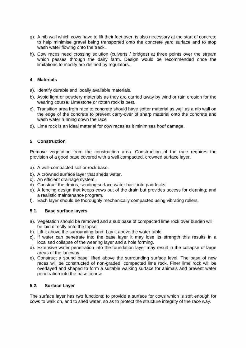
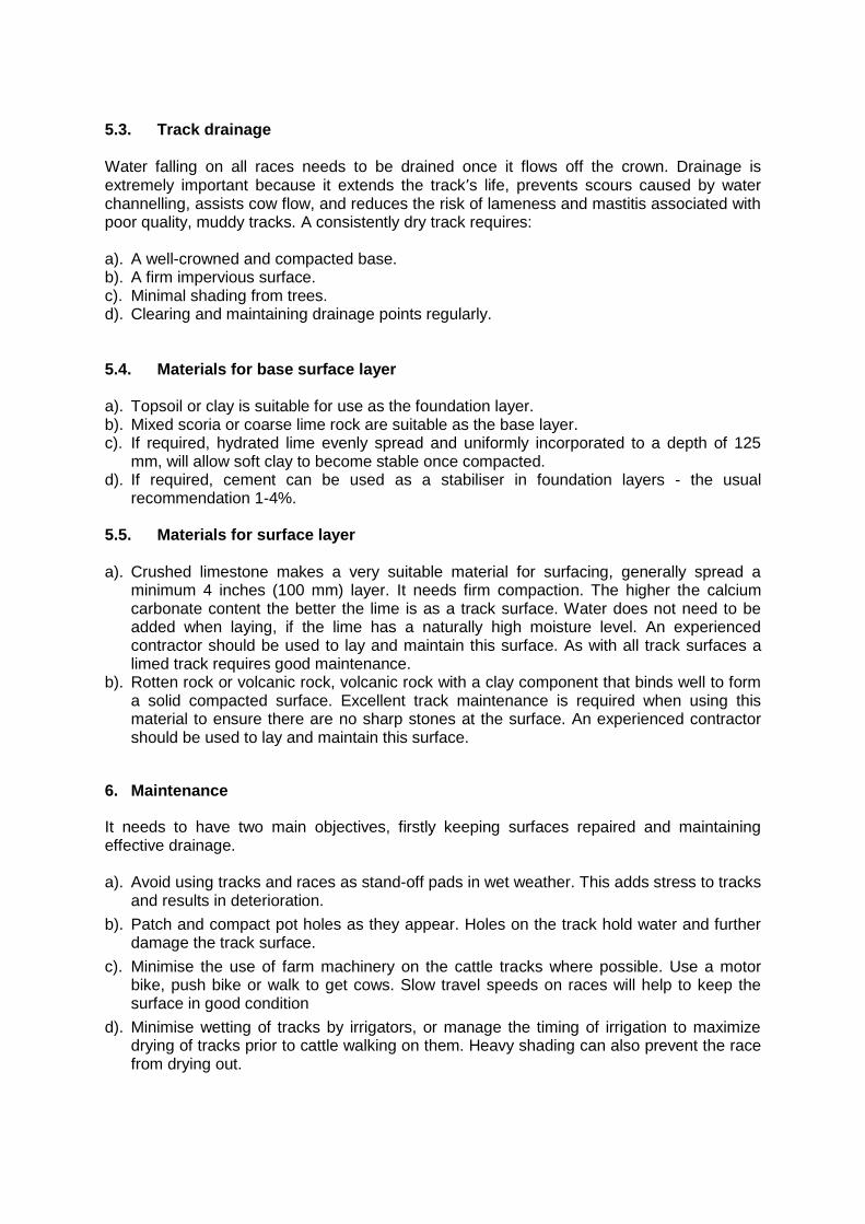
d). Camber - the curve of the surface should be 3% to allow for drainage to maintain track condition (Figure 1).
e). Gradient - If the race is too steep water will run down the length of the race rather than across the width of the race. Erosion and breakdown of the race surface will result. Do not have the race too steep. Gradients greater than 3:1 are too steep for stock and above 10:1 is too steep for vehicles (4:1 for a 4wd tractor).
f). Width - race width is very important for cow flow. (Table 1) The widths noted refer to the walking space only – not drainage channels or grassed edges
g). Drainage - The shape and drainage of tracks is extremely important as it will have an impact on cow flow, lameness, and the repairs and maintenance which will be required. See below for detail.
h). Gateways should be of a sufficient width to allow free flowing transition of animals without causing pressure points. Gate widths of 6m-8m are acceptable.
i). Direct more attention and capital expenditure to races which are most frequently used e.g., those closest to the milking parlour.
Factors mentioned above are critical to minimise lameness.
3. Design Consideration
a). Camber – maximum crossfall of 3 %. Otherwise the effect will be cows will not utilizing the whole track width causing cow flow issues.
b). Width –6.0 meters available for cows to walk, distance from fence to fence 7 meters.
Race widths
Herd Size (Cows) Race Width (m)
< 120 5.0
120 – 250 5.5
250 – 330 6.0
330 – 450 6.5
> 450 Herd will be split, refer above
Table 1 – It does not include drainage channels or grassed edges
c). Drainage - Water falling on races needs to be drained away once it flows off the crown. Poor drainage results in lameness as dirty hooves are pre-dispose to infections. Construct 1 meter kikuyu filter berm to keep sentiment washed off into drains.
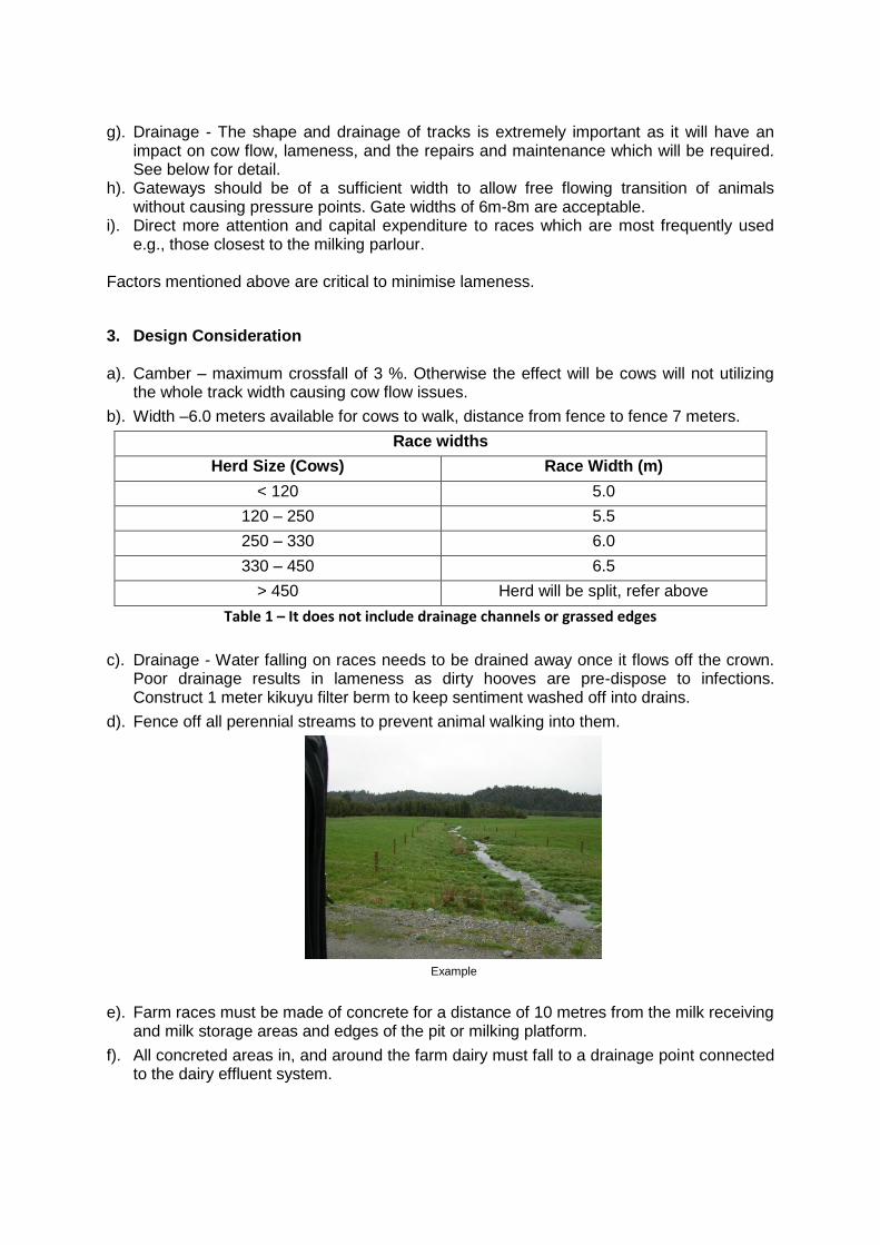
d). Fence off all perennial streams to prevent animal walking into them.
Example
e). Farm races must be made of concrete for a distance of 10 metres from the milk receiving and milk storage areas and edges of the pit or milking platform.
f). All concreted areas in, and around the farm dairy must fall to a drainage point connected to the dairy effluent system.
g). A nib wall which cows have to lift their feet over, is also necessary at the start of concrete to help minimise gravel being transported onto the concrete yard surface and to stop wash water flowing onto the track.
h). Cow races need crossing solution (culverts / bridges) at three points over the stream which passes through the dairy farm. Design would be recommended once the limitations to modify are defined by regulators.
4. Materials
a). Identify durable and locally available materials.
b). Avoid light or powdery materials as they are carried away by wind or rain erosion for the wearing course. Limestone or rotten rock is best.
c). Transition area from race to concrete should have softer material as well as a nib wall on the edge of the concrete to prevent carry-over of sharp material onto the concrete and wash water running down the race
d). Lime rock is an ideal material for cow races as it minimises hoof damage.
5. Construction Remove vegetation from the construction area. Construction of the race requires the provision of a good base covered with a well compacted, crowned surface layer.
a). A well-compacted soil or rock base.
b). A crowned surface layer that sheds water. c). An efficient drainage system. d). Construct the drains, sending surface water back into paddocks. e). A fencing design that keeps cows out of the drain but provides access for cleaning; and
a realistic maintenance program. f). Each layer should be thoroughly mechanically compacted using vibrating rollers. 5.1. Base surface layers
a). Vegetation should be removed and a sub base of compacted lime rock over burden will
be laid directly onto the topsoil. b). Lift it above the surrounding land. Lay it above the water table. c). If water can penetrate into the base layer it may lose its strength this results in a
localised collapse of the wearing layer and a hole forming. d). Extensive water penetration into the foundation layer may result in the collapse of large
areas of the laneway e). Construct a sound base, lifted above the surrounding surface level. The base of new
races will be constructed of non-graded, compacted lime rock. Finer lime rock will be overlayed and shaped to form a suitable walking surface for animals and prevent water penetration into the base course
5.2. Surface Layer The surface layer has two functions; to provide a surface for cows which is soft enough for cows to walk on, and to shed water, so as to protect the structure integrity of the race way.
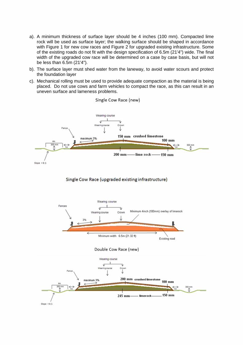
a). A minimum thickness of surface layer should be 4 inches (100 mm). Compacted lime rock will be used as surface layer; the walking surface should be shaped in accordance with Figure 1 for new cow races and Figure 2 for upgraded existing infrastructure. Some of the existing roads do not fit with the design specification of 6.5m (21'4") wide. The final width of the upgraded cow race will be determined on a case by case basis, but will not be less than 6.5m (21'4").
b). The surface layer must shed water from the laneway, to avoid water scours and protect the foundation layer
c). Mechanical rolling must be used to provide adequate compaction as the material is being placed. Do not use cows and farm vehicles to compact the race, as this can result in an uneven surface and lameness problems.
5.3. Track drainage Water falling on all races needs to be drained once it flows off the crown. Drainage is extremely important because it extends the track’s life, prevents scours caused by water channelling, assists cow flow, and reduces the risk of lameness and mastitis associated with poor quality, muddy tracks. A consistently dry track requires: a). A well-crowned and compacted base. b). A firm impervious surface. c). Minimal shading from trees. d). Clearing and maintaining drainage points regularly.
5.4. Materials for base surface layer a). Topsoil or clay is suitable for use as the foundation layer. b). Mixed scoria or coarse lime rock are suitable as the base layer. c). If required, hydrated lime evenly spread and uniformly incorporated to a depth of 125
mm, will allow soft clay to become stable once compacted. d). If required, cement can be used as a stabiliser in foundation layers - the usual
recommendation 1-4%. 5.5. Materials for surface layer
a). Crushed limestone makes a very suitable material for surfacing, generally spread a
minimum 4 inches (100 mm) layer. It needs firm compaction. The higher the calcium carbonate content the better the lime is as a track surface. Water does not need to be added when laying, if the lime has a naturally high moisture level. An experienced contractor should be used to lay and maintain this surface. As with all track surfaces a limed track requires good maintenance.
b). Rotten rock or volcanic rock, volcanic rock with a clay component that binds well to form a solid compacted surface. Excellent track maintenance is required when using this material to ensure there are no sharp stones at the surface. An experienced contractor should be used to lay and maintain this surface.
6. Maintenance
It needs to have two main objectives, firstly keeping surfaces repaired and maintaining effective drainage. a). Avoid using tracks and races as stand-off pads in wet weather. This adds stress to tracks
and results in deterioration.
b). Patch and compact pot holes as they appear. Holes on the track hold water and further damage the track surface.
c). Minimise the use of farm machinery on the cattle tracks where possible. Use a motor bike, push bike or walk to get cows. Slow travel speeds on races will help to keep the surface in good condition
d). Minimise wetting of tracks by irrigators, or manage the timing of irrigation to maximize drying of tracks prior to cattle walking on them. Heavy shading can also prevent the race from drying out.
7. Appendix
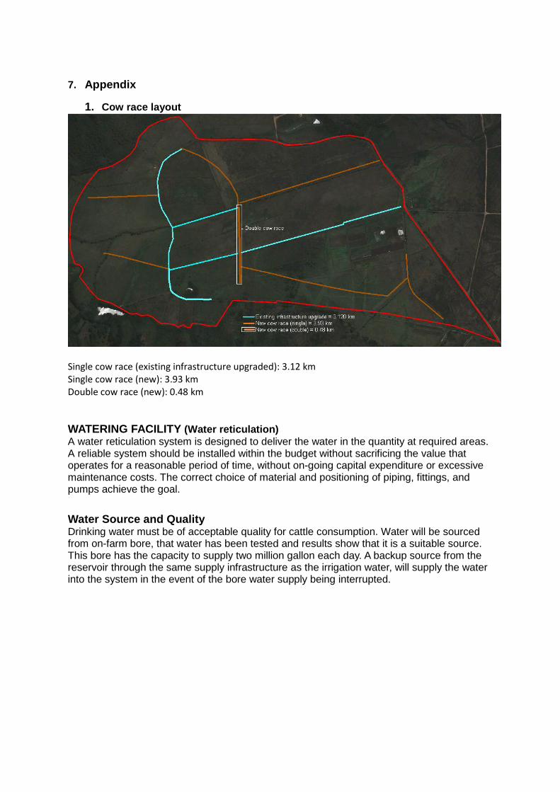
1. Cow race layout
Single cow race (existing infrastructure upgraded): 3.12 km Single cow race (new): 3.93 km Double cow race (new): 0.48 km
WATERING FACILITY (Water reticulation)
A water reticulation system is designed to deliver the water in the quantity at required areas. A reliable system should be installed within the budget without sacrificing the value that operates for a reasonable period of time, without on-going capital expenditure or excessive maintenance costs. The correct choice of material and positioning of piping, fittings, and pumps achieve the goal.
Water Source and Quality Drinking water must be of acceptable quality for cattle consumption. Water will be sourced from on-farm bore, that water has been tested and results show that it is a suitable source. This bore has the capacity to supply two million gallon each day. A backup source from the reservoir through the same supply infrastructure as the irrigation water, will supply the water into the system in the event of the bore water supply being interrupted.
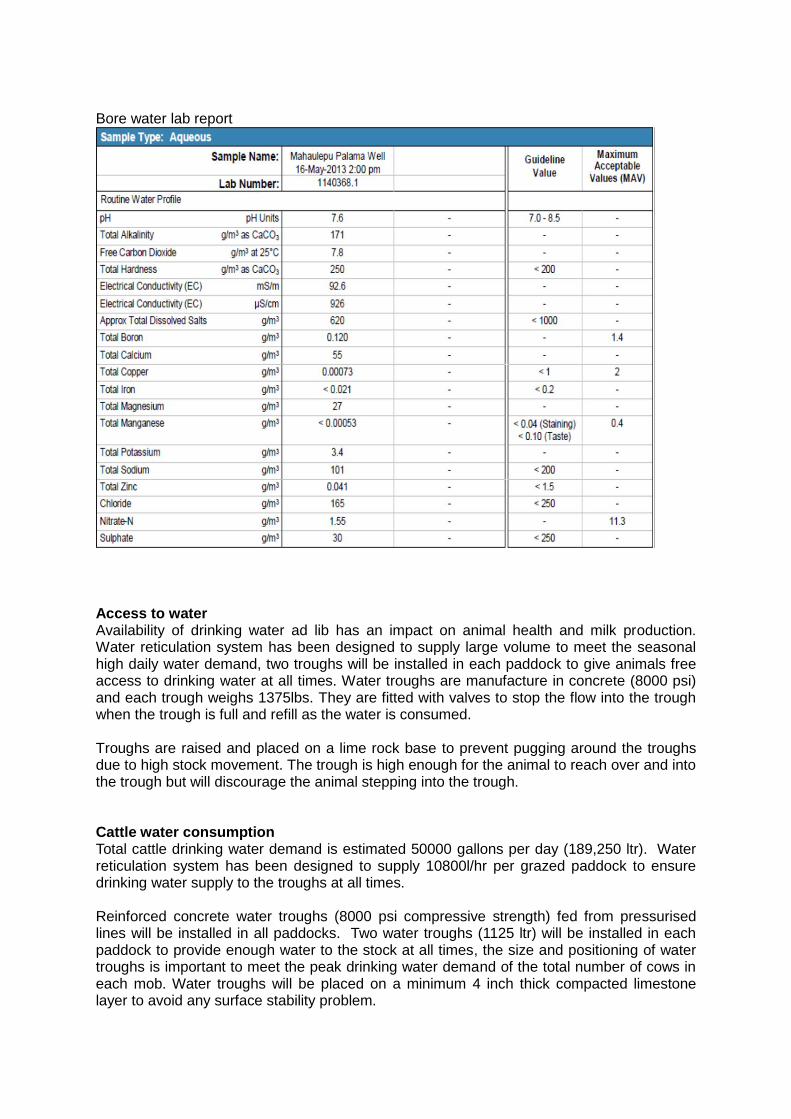
Bore water lab report
Access to water Availability of drinking water ad lib has an impact on animal health and milk production. Water reticulation system has been designed to supply large volume to meet the seasonal high daily water demand, two troughs will be installed in each paddock to give animals free access to drinking water at all times. Water troughs are manufacture in concrete (8000 psi) and each trough weighs 1375lbs. They are fitted with valves to stop the flow into the trough when the trough is full and refill as the water is consumed. Troughs are raised and placed on a lime rock base to prevent pugging around the troughs due to high stock movement. The trough is high enough for the animal to reach over and into the trough but will discourage the animal stepping into the trough. Cattle water consumption Total cattle drinking water demand is estimated 50000 gallons per day (189,250 ltr). Water reticulation system has been designed to supply 10800l/hr per grazed paddock to ensure drinking water supply to the troughs at all times. Reinforced concrete water troughs (8000 psi compressive strength) fed from pressurised lines will be installed in all paddocks. Two water troughs (1125 ltr) will be installed in each paddock to provide enough water to the stock at all times, the size and positioning of water troughs is important to meet the peak drinking water demand of the total number of cows in each mob. Water troughs will be placed on a minimum 4 inch thick compacted limestone layer to avoid any surface stability problem.
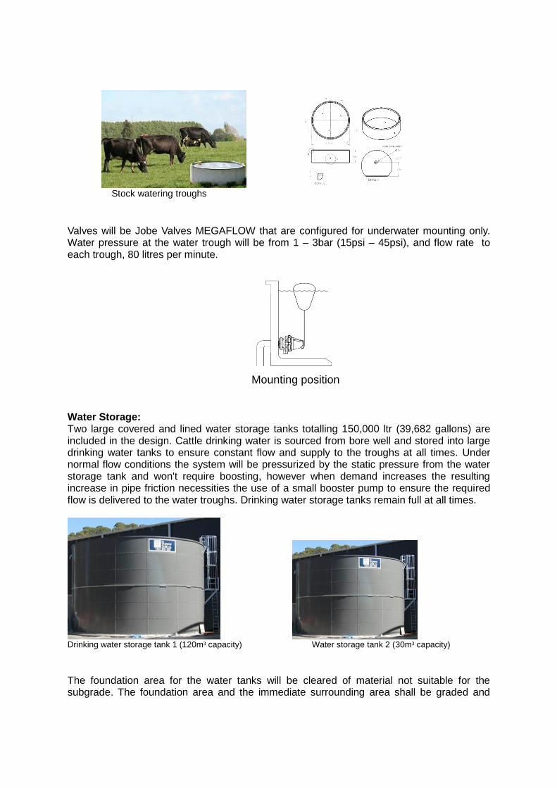
Stock watering troughs
Valves will be Jobe Valves MEGAFLOW that are configured for underwater mounting only. Water pressure at the water trough will be from 1 – 3bar (15psi – 45psi), and flow rate to each trough, 80 litres per minute.
Mounting position
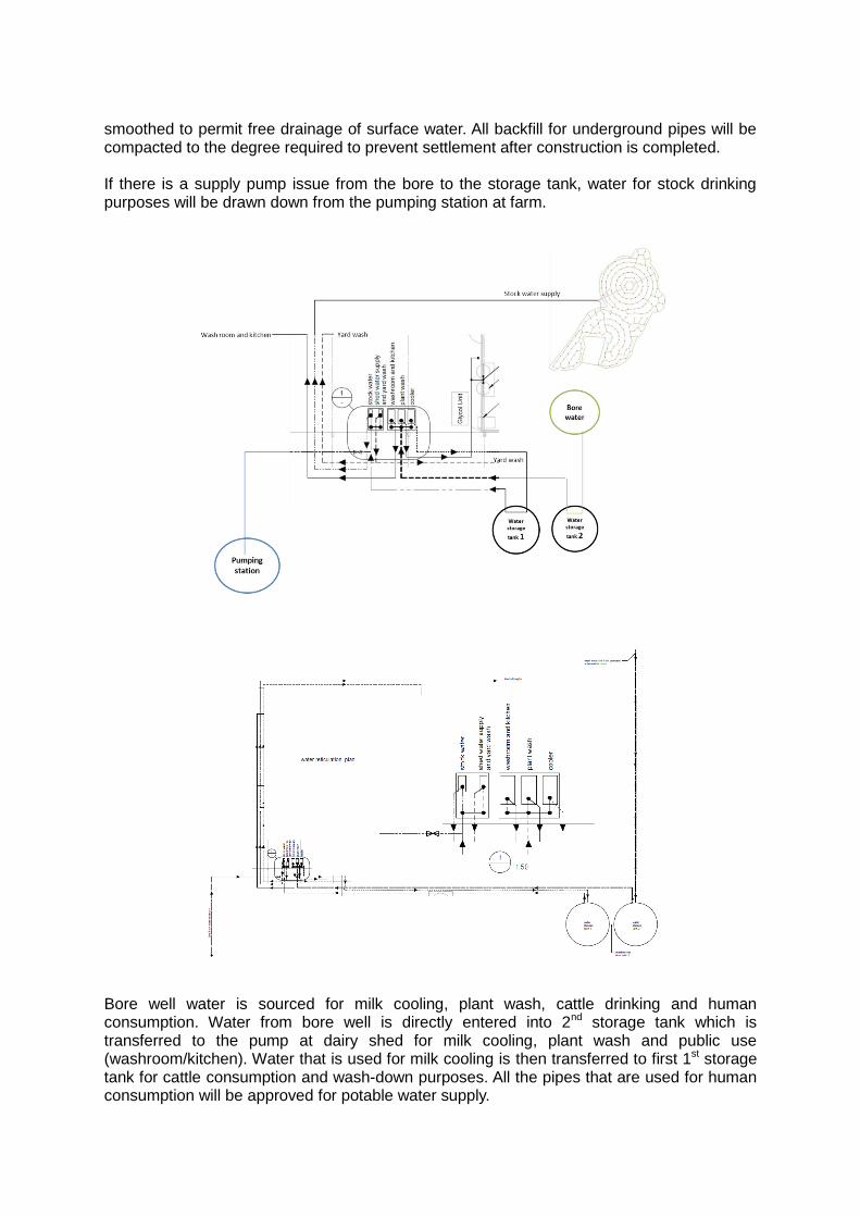
Water Storage: Two large covered and lined water storage tanks totalling 150,000 ltr (39,682 gallons) are included in the design. Cattle drinking water is sourced from bore well and stored into large drinking water tanks to ensure constant flow and supply to the troughs at all times. Under normal flow conditions the system will be pressurized by the static pressure from the water storage tank and won't require boosting, however when demand increases the resulting increase in pipe friction necessities the use of a small booster pump to ensure the required flow is delivered to the water troughs. Drinking water storage tanks remain full at all times.
Drinking water storage tank 1 (120m³ capacity) Water storage tank 2 (30m³ capacity)
The foundation area for the water tanks will be cleared of material not suitable for the subgrade. The foundation area and the immediate surrounding area shall be graded and
smoothed to permit free drainage of surface water. All backfill for underground pipes will be compacted to the degree required to prevent settlement after construction is completed. If there is a supply pump issue from the bore to the storage tank, water for stock drinking purposes will be drawn down from the pumping station at farm.
Bore well water is sourced for milk cooling, plant wash, cattle drinking and human consumption. Water from bore well is directly entered into 2nd storage tank which is transferred to the pump at dairy shed for milk cooling, plant wash and public use (washroom/kitchen). Water that is used for milk cooling is then transferred to first 1st storage tank for cattle consumption and wash-down purposes. All the pipes that are used for human consumption will be approved for potable water supply.
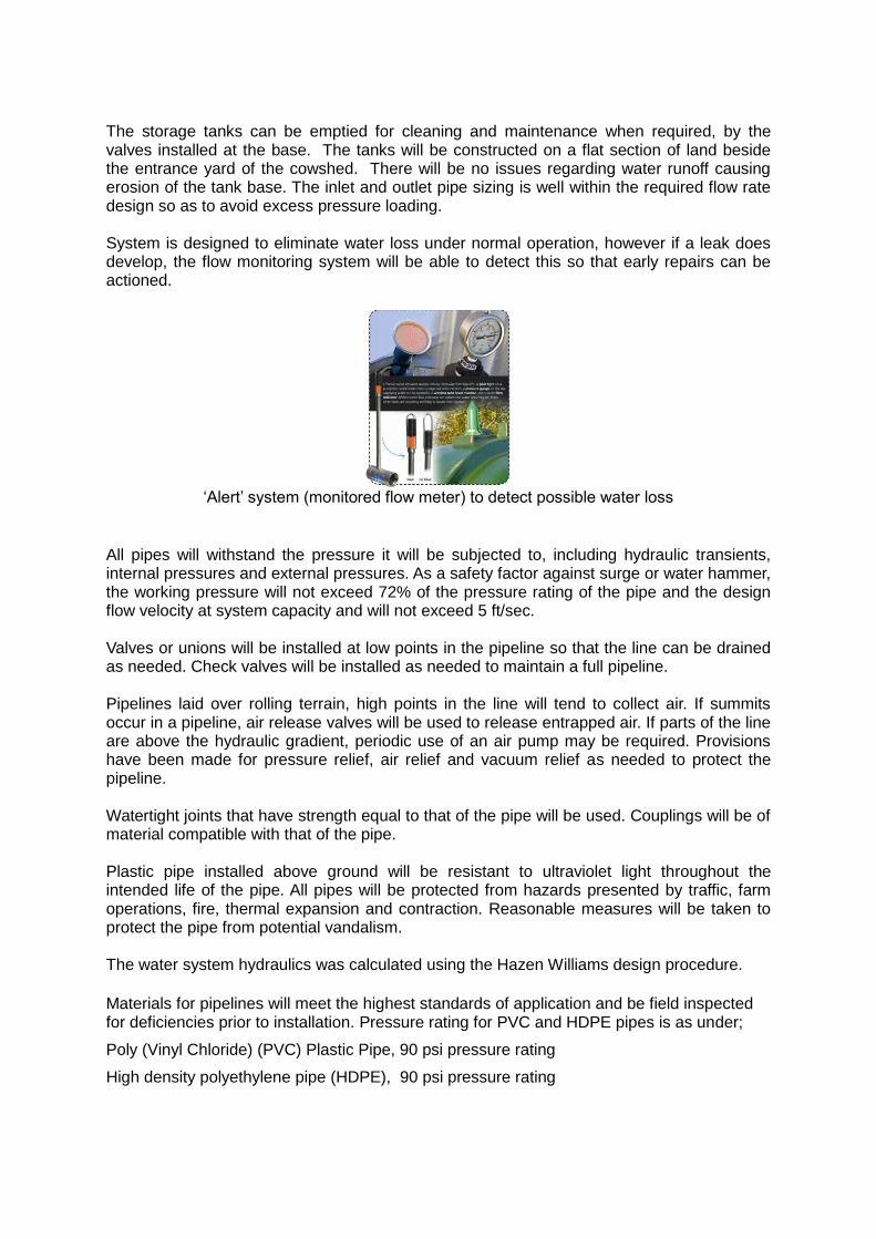
The storage tanks can be emptied for cleaning and maintenance when required, by the valves installed at the base. The tanks will be constructed on a flat section of land beside the entrance yard of the cowshed. There will be no issues regarding water runoff causing erosion of the tank base. The inlet and outlet pipe sizing is well within the required flow rate design so as to avoid excess pressure loading. System is designed to eliminate water loss under normal operation, however if a leak does develop, the flow monitoring system will be able to detect this so that early repairs can be actioned.
‘Alert’ system (monitored flow meter) to detect possible water loss
All pipes will withstand the pressure it will be subjected to, including hydraulic transients, internal pressures and external pressures. As a safety factor against surge or water hammer, the working pressure will not exceed 72% of the pressure rating of the pipe and the design flow velocity at system capacity and will not exceed 5 ft/sec. Valves or unions will be installed at low points in the pipeline so that the line can be drained as needed. Check valves will be installed as needed to maintain a full pipeline. Pipelines laid over rolling terrain, high points in the line will tend to collect air. If summits occur in a pipeline, air release valves will be used to release entrapped air. If parts of the line are above the hydraulic gradient, periodic use of an air pump may be required. Provisions have been made for pressure relief, air relief and vacuum relief as needed to protect the pipeline. Watertight joints that have strength equal to that of the pipe will be used. Couplings will be of material compatible with that of the pipe. Plastic pipe installed above ground will be resistant to ultraviolet light throughout the intended life of the pipe. All pipes will be protected from hazards presented by traffic, farm operations, fire, thermal expansion and contraction. Reasonable measures will be taken to protect the pipe from potential vandalism. The water system hydraulics was calculated using the Hazen Williams design procedure.
Materials for pipelines will meet the highest standards of application and be field inspected for deficiencies prior to installation. Pressure rating for PVC and HDPE pipes is as under;
Poly (Vinyl Chloride) (PVC) Plastic Pipe, 90 psi pressure rating
High density polyethylene pipe (HDPE), 90 psi pressure rating
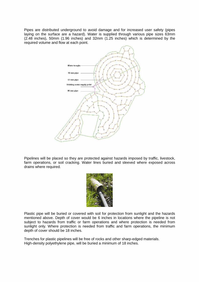
Pipes are distributed underground to avoid damage and for increased user safety (pipes laying on the surface are a hazard). Water is supplied through various pipe sizes 63mm (2.48 inches), 50mm (1.96 inches) and 32mm (1.25 inches) which is determined by the required volume and flow at each point.
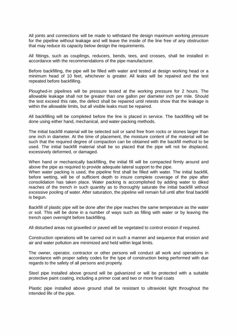
Pipelines will be placed so they are protected against hazards imposed by traffic, livestock, farm operations, or soil cracking. Water lines buried and sleeved where exposed across drains where required.
Plastic pipe will be buried or covered with soil for protection from sunlight and the hazards mentioned above. Depth of cover would be 6 inches in locations where the pipeline is not subject to hazards from traffic or farm operations and where protection is needed from sunlight only. Where protection is needed from traffic and farm operations, the minimum depth of cover should be 18 inches. Trenches for plastic pipelines will be free of rocks and other sharp-edged materials. High-density polyethylene pipe, will be buried a minimum of 18 inches.
All joints and connections will be made to withstand the design maximum working pressure for the pipeline without leakage and will leave the inside of the line free of any obstruction that may reduce its capacity below design the requirements. All fittings, such as couplings, reducers, bends, tees, and crosses, shall be installed in accordance with the recommendations of the pipe manufacturer. Before backfilling, the pipe will be filled with water and tested at design working head or a minimum head of 10 feet, whichever is greater. All leaks will be repaired and the test repeated before backfilling. Ploughed-in pipelines will be pressure tested at the working pressure for 2 hours. The allowable leakage shall not be greater than one gallon per diameter inch per mile. Should the test exceed this rate, the defect shall be repaired until retests show that the leakage is within the allowable limits, but all visible leaks must be repaired. All backfilling will be completed before the line is placed in service. The backfilling will be done using either hand, mechanical, and water-packing methods. The initial backfill material will be selected soil or sand free from rocks or stones larger than one inch in diameter. At the time of placement, the moisture content of the material will be such that the required degree of compaction can be obtained with the backfill method to be used. The initial backfill material shall be so placed that the pipe will not be displaced, excessively deformed, or damaged. When hand or mechanically backfilling, the initial fill will be compacted firmly around and above the pipe as required to provide adequate lateral support to the pipe. When water packing is used, the pipeline first shall be filled with water. The initial backfill, before wetting, will be of sufficient depth to insure complete coverage of the pipe after consolidation has taken place. Water packing is accomplished by adding water to diked reaches of the trench in such quantity as to thoroughly saturate the initial backfill without excessive pooling of water. After saturation, the pipeline will remain full until after final backfill is begun. Backfill of plastic pipe will be done after the pipe reaches the same temperature as the water or soil. This will be done in a number of ways such as filling with water or by leaving the trench open overnight before backfilling. All disturbed areas not gravelled or paved will be vegetated to control erosion if required. Construction operations will be carried out in such a manner and sequence that erosion and air and water pollution are minimized and held within legal limits. The owner, operator, contractor or other persons will conduct all work and operations in accordance with proper safety codes for the type of construction being performed with due regards to the safety of all persons and property. Steel pipe installed above ground will be galvanized or will be protected with a suitable protective paint coating, including a primer coat and two or more final coats Plastic pipe installed above ground shall be resistant to ultraviolet light throughout the intended life of the pipe.
All pipes shall be protected from hazards presented by traffic, farm operations, fire, thermal expansion and contraction. Reasonable measures should be taken to protect the pipe from potential vandalism.
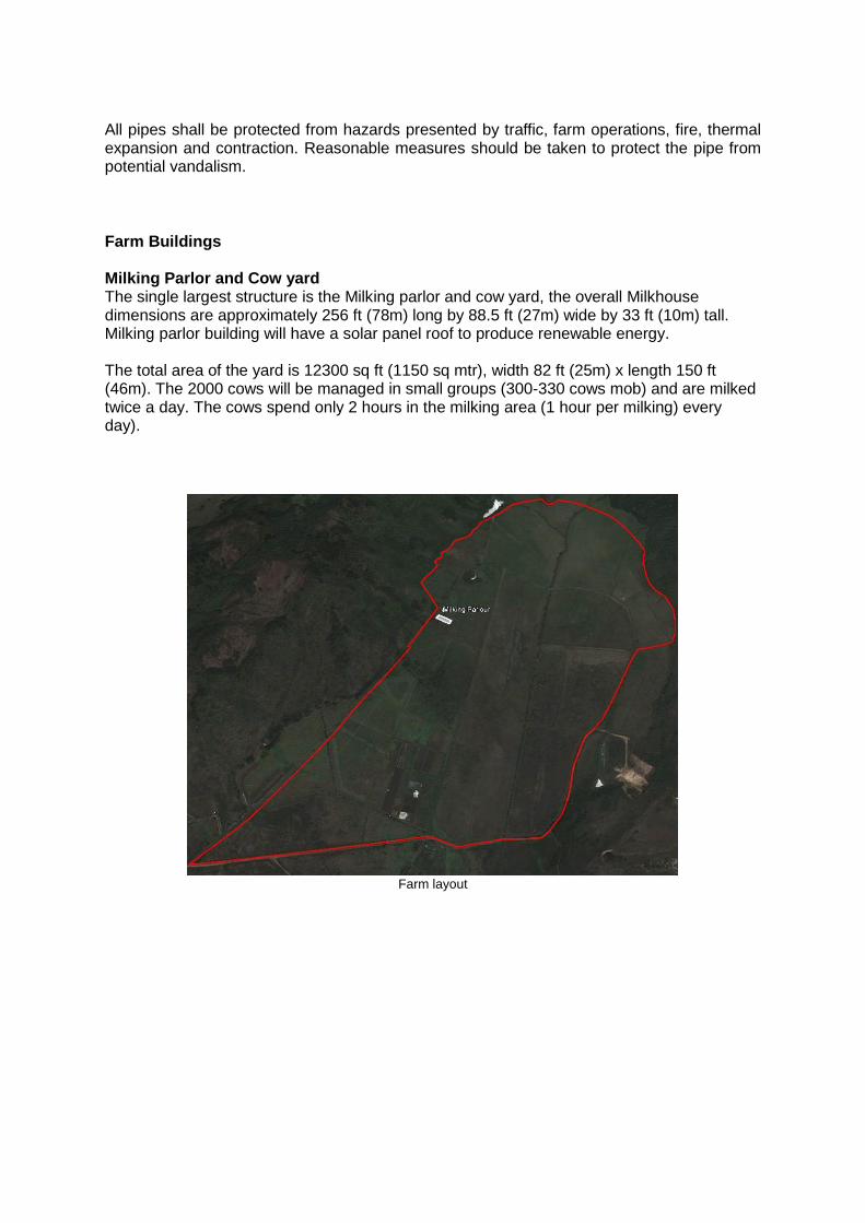
Farm Buildings Milking Parlor and Cow yard The single largest structure is the Milking parlor and cow yard, the overall Milkhouse dimensions are approximately 256 ft (78m) long by 88.5 ft (27m) wide by 33 ft (10m) tall. Milking parlor building will have a solar panel roof to produce renewable energy. The total area of the yard is 12300 sq ft (1150 sq mtr), width 82 ft (25m) x length 150 ft (46m). The 2000 cows will be managed in small groups (300-330 cows mob) and are milked twice a day. The cows spend only 2 hours in the milking area (1 hour per milking) every day).
Farm layout
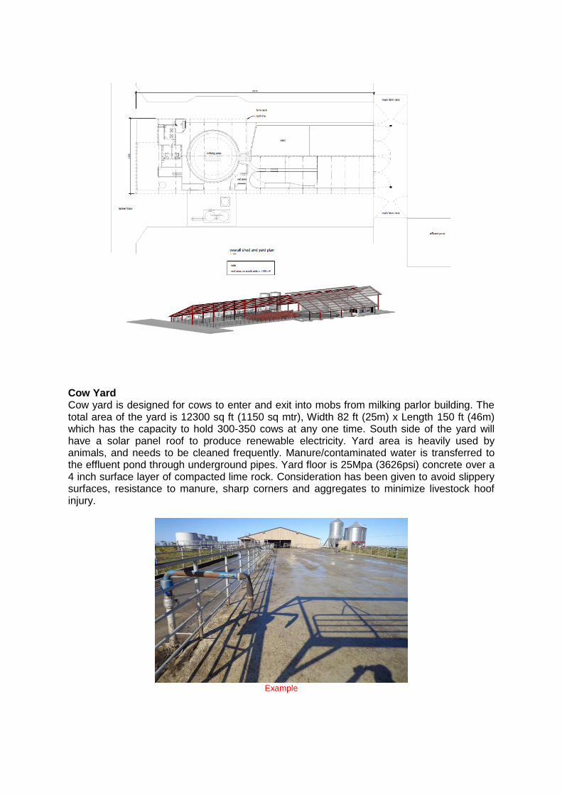
Cow Yard Cow yard is designed for cows to enter and exit into mobs from milking parlor building. The total area of the yard is 12300 sq ft (1150 sq mtr), Width 82 ft (25m) x Length 150 ft (46m) which has the capacity to hold 300-350 cows at any one time. South side of the yard will have a solar panel roof to produce renewable electricity. Yard area is heavily used by animals, and needs to be cleaned frequently. Manure/contaminated water is transferred to the effluent pond through underground pipes. Yard floor is 25Mpa (3626psi) concrete over a 4 inch surface layer of compacted lime rock. Consideration has been given to avoid slippery surfaces, resistance to manure, sharp corners and aggregates to minimize livestock hoof injury.
Example
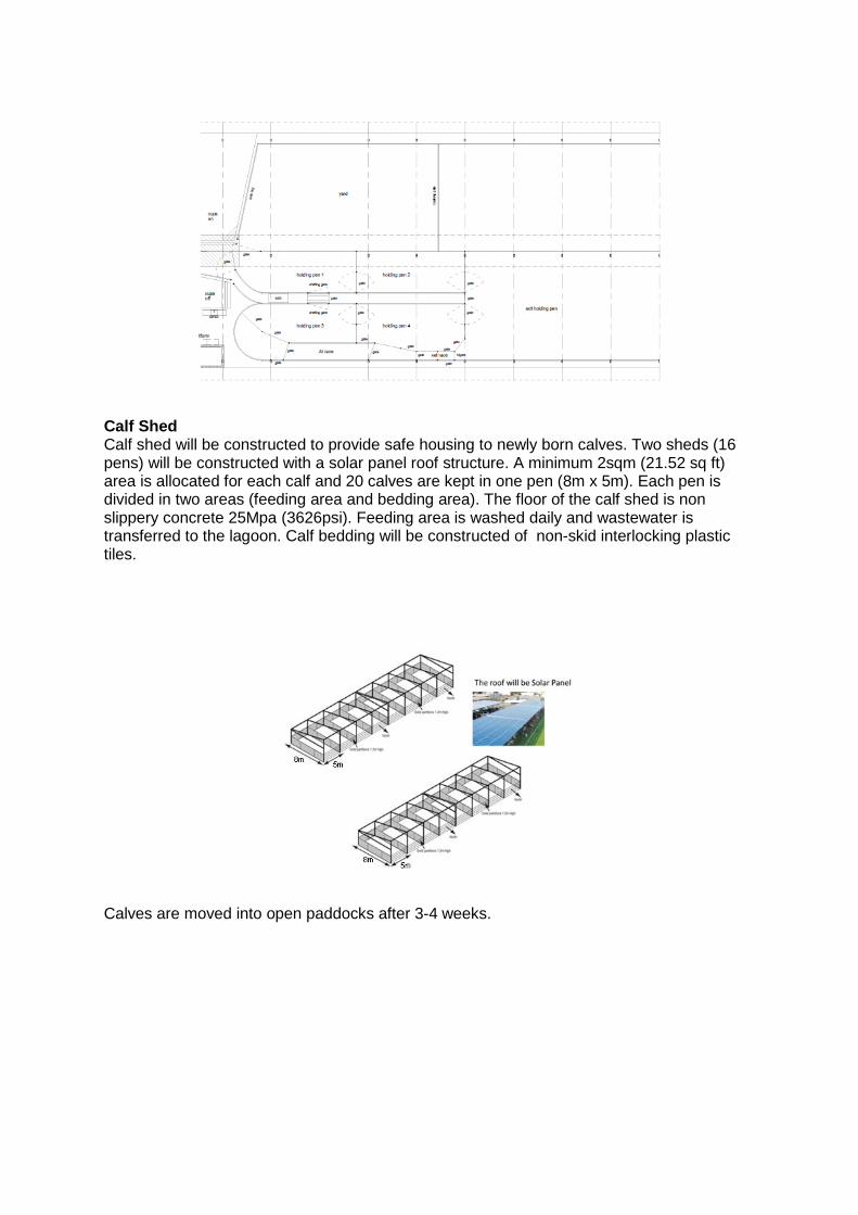
Calf Shed Calf shed will be constructed to provide safe housing to newly born calves. Two sheds (16 pens) will be constructed with a solar panel roof structure. A minimum 2sqm (21.52 sq ft) area is allocated for each calf and 20 calves are kept in one pen (8m x 5m). Each pen is divided in two areas (feeding area and bedding area). The floor of the calf shed is non slippery concrete 25Mpa (3626psi). Feeding area is washed daily and wastewater is transferred to the lagoon. Calf bedding will be constructed of non-skid interlocking plastic tiles.
Calves are moved into open paddocks after 3-4 weeks.

Implement Shed Implement shed or workshop will be constructed for equipment and tools storage and farm machinery parking. Total area required for implement shed is 20m (L) x 8m (W), this building requires a very basic structure with solar panel roof on it, floor of the building will be 25Mpa (3626 psi) concrete. Solar panel roof
ROOF RUNOFF STRUCTURE Roof runoff structure will be designed to collect rain water from milking parlor building which is later used for irrigation. Roof runoff structure will be designed with a minimum design life of ten years and has minimum chances of damage by livestock and equipment. To design roof runoff structure, 25-years, 24-hour storm event has been taken into account. The maximum 24-hour, 25-years storm event at Mahaulepu is 6.6 inches or 168mm which was recorded on 03/02/1989.
*Data sourced from U.S. Department of Commerce National Oceanic & Atmospheric Administration
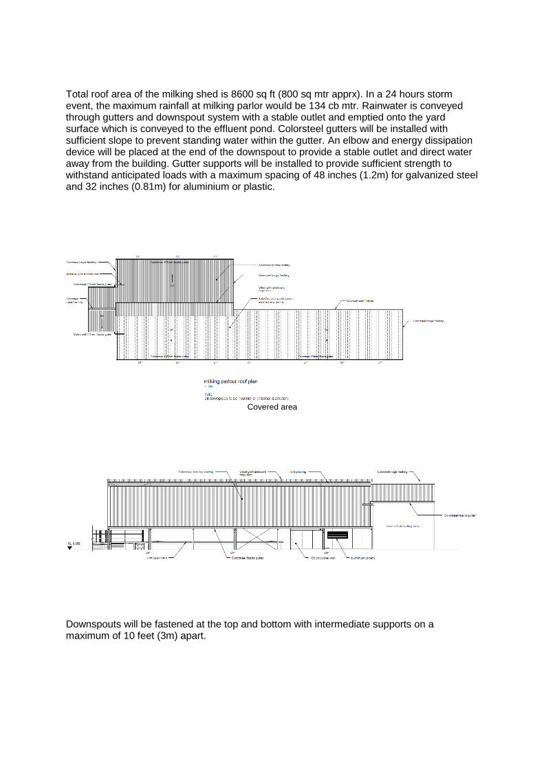
Total roof area of the milking shed is 8600 sq ft (800 sq mtr apprx). In a 24 hours storm event, the maximum rainfall at milking parlor would be 134 cb mtr. Rainwater is conveyed through gutters and downspout system with a stable outlet and emptied onto the yard surface which is conveyed to the effluent pond. Colorsteel gutters will be installed with sufficient slope to prevent standing water within the gutter. An elbow and energy dissipation device will be placed at the end of the downspout to provide a stable outlet and direct water away from the building. Gutter supports will be installed to provide sufficient strength to withstand anticipated loads with a maximum spacing of 48 inches (1.2m) for galvanized steel and 32 inches (0.81m) for aluminium or plastic.
Covered area
Downspouts will be fastened at the top and bottom with intermediate supports on a maximum of 10 feet (3m) apart.
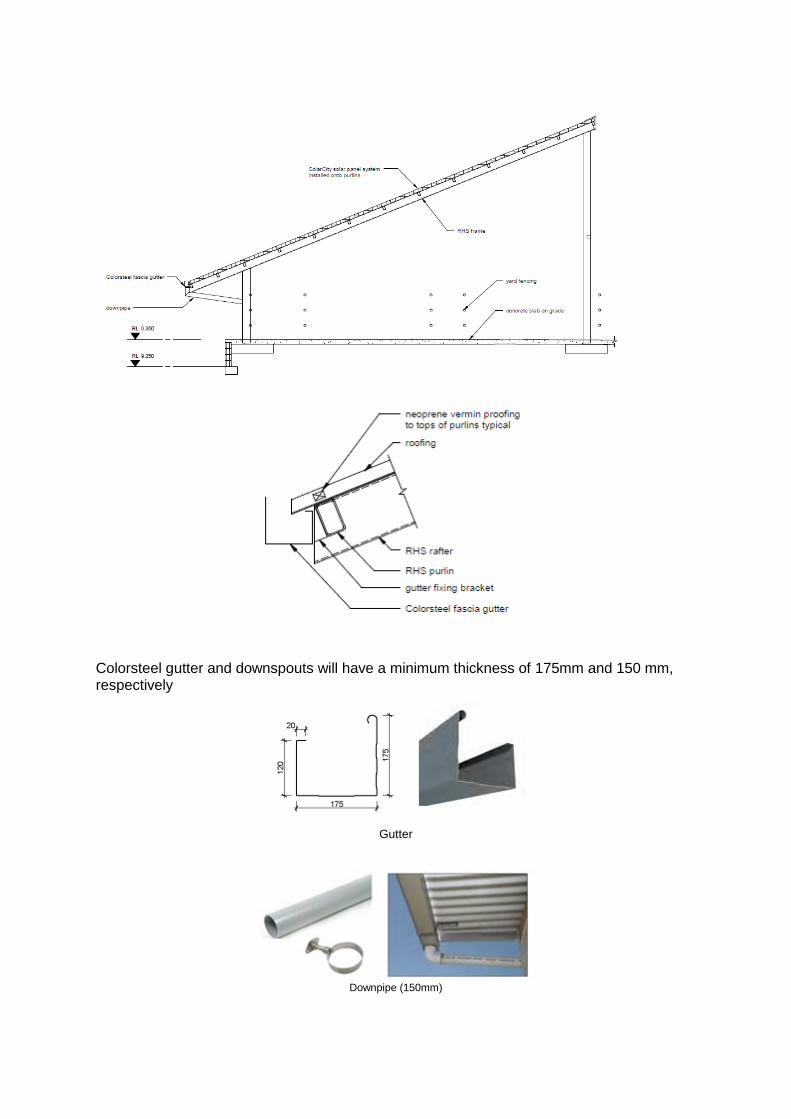
Colorsteel gutter and downspouts will have a minimum thickness of 175mm and 150 mm, respectively
Gutter
Downpipe (150mm)
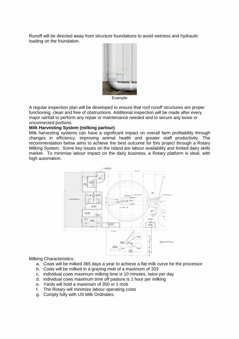
Runoff will be directed away from structure foundations to avoid wetness and hydraulic loading on the foundation.
Example
A regular inspection plan will be developed to ensure that roof runoff structures are proper functioning, clean and free of obstructions. Additional inspection will be made after every major rainfall to perform any repair or maintenance needed and to secure any loose or unconnected portions. Milk Harvesting System (milking parlour) Milk harvesting systems can have a significant impact on overall farm profitability through changes in efficiency, improving animal health and greater staff productivity. The recommendation below aims to achieve the best outcome for this project through a Rotary Milking System. Some key issues on the Island are labour availability and limited dairy skills market. To minimise labour impact on the dairy business, a Rotary platform is ideal, with high automation.
Milking Characteristics:
a. Cows will be milked 365 days a year to achieve a flat milk curve for the processor b. Cows will be milked in a grazing mob of a maximum of 333 c. individual cows maximum milking time is 10 minutes, twice per day d. individual cows maximum time off pasture is 1 hour per milking e. Yards will hold a maximum of 350 or 1 mob f. The Rotary will minimize labour operating costs g. Comply fully with US Milk Ordinates.
Milk quality Target
a). Milk to be cooled below 2°C by Plate Heat Exchanger (PHE) using a Glycol solution and
delivered directly into the Tanker truck for offsite storage; b). Compliant with the Dean Foods quality standards
MILKING SYSTEM
General Requirements
The milking plant in a farm dairy must be designed and maintained to ensure that the materials and substances coming into contact with the milk do not contaminate it or cause the milk to deteriorate. The supplier and/or installer of the milking system must demonstrate that all of the milk contact surfaces and the installation are safe for foods.
Design Factors
The milking system needs to be designed: a). to minimise physical damage to the milk while it is being harvested; b). to allow for efficient internal cleaning; and c). to drain condensation and other liquids. d). All pipelines must be capable of being readily drained. Airlines and interceptors (where
fitted) must be self-draining. e). The receiver airline must be connected to either an interceptor or a self-draining sanitary
trap. f). The design of the milking plant can affect milk quality, both microbiologically and
physically. g). Cluster claws with a form of automatic vacuum shut-off device or automatic cluster
removal device form part of the milking system. These have been shown to prevent excessive air, manure and soils from entering the plant during cluster changing or drop off, thus resulting in greater vacuum stability and better quality milk.
h). An airflow meter connection point at or near the interceptor. i). Installed to allow easy accessibility for cleaning. j). Able to be cleaned either manually or preferably in-place under normal conditions of
installation and use. k). Capable of being drained, preferably self-drained, and all milk and air lines sloped to
drain points, so that no pools of standing liquid are left after cleaning.
Material
All milk contact and cleaning system surfaces will be from suitable materials which are smooth, free from cracks and crevices, impervious, durable, and are cleaned adequately by normal procedures.
a). In the completed or installed form, the material must not release toxic substances or tainting substances.
b). The material must be able to be cleaned (free from visible contamination and having no measurable effect on the quality of milk) by approved detergents and sanitizers following cleaning procedures specified by the manufacturer or detergent supplier.
c). Resistant to water and water vapour. d). Resistant to milk and chemicals. e). Resistant to physical damage. f). Resistant to attack by micro-organisms (.maintain its original properties after being
subjected to temperature changes that may occur in a farm dairy. Normally this will be from minus 20°C to plus 100°C unless otherwise specified by the manufacturer).
g). Must be designed and manufactured to discourage stress corrosion, crevice corrosion or any other corrosion which could cause hygiene or contamination problems.
Rotary Milking System Technical Requirements
a). Rotary Milking System of 60 Clusters that provides for a throughput of 360 cows every
hour and allows for a maximum milking time of 6 hours approximately per milking and 12 hours per day;
b). Galvanized bail structure with top support rail. No welding on the Galvanised structure above cow standing area;
c). Double beam platform, rollers must not have bearings; d). Control consoles build with stainless steel and waterproof switches, forward with
adjustable speed, inch reverse, cow crush switch at entry, rope stop and emergency stop or star switch around full perimeter of rotary. All safety mechanisms to equal or exceed Guide in appendix one;
e). Electric platform drive; f). Cluster needs to meet the following, high-yielding, fast milking, and good sealing
properties around the teat, resist impact damage, minimal distortion and minimal air admission during cluster attachment. Front/Rear pulsation split;
g). Pulsator needs to be accurate; h). Milk lines and receivers need to be sized correctly to allow milk lines provide good
stratified milk flow and aid vacuum stability in the milking system; i). Milk pumping needs to comply with international industry hygiene standards, quiet in
operation, cost effective and requiring minimal maintenance (one for milking and one for washing);
j). Milk filters need to have high quality fabrication and material to ensure high filtering performance, also to operate with CIP (Cleaning in place).Need to be sized at 6 cm2 per cow. Minimum of 620 cows per filter;
k). Vacuum system controls that cancel much of the noise generated, extremely accurate and reduce power consumption, variable speed drive;
l). Automatic CIP system easy to use and deliver a set flow rate of wash water to the cluster ensuring maximum hygiene. Cluster washers must be adjustable for flow;
m). Overall minimal maintenance; n). Full control from the milking point using automated cluster removers for efficiency and
cow restraints. o). Milk pump controls to reduce water usage and interlocks eliminating the risk of
accidental cooling of hot wash water. p). Two underpasses opposite to the cups on one by office area and the other for pipes for
maintenance,
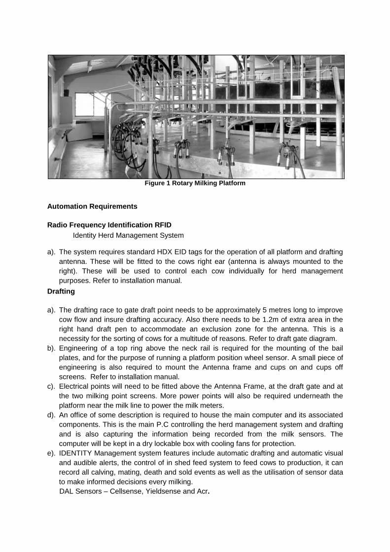
Figure 1 Rotary Milking Platform
Automation Requirements
Radio Frequency Identification RFID
Identity Herd Management System a). The system requires standard HDX EID tags for the operation of all platform and drafting
antenna. These will be fitted to the cows right ear (antenna is always mounted to the
right). These will be used to control each cow individually for herd management
purposes. Refer to installation manual.
Drafting
a). The drafting race to gate draft point needs to be approximately 5 metres long to improve
cow flow and insure drafting accuracy. Also there needs to be 1.2m of extra area in the
right hand draft pen to accommodate an exclusion zone for the antenna. This is a
necessity for the sorting of cows for a multitude of reasons. Refer to draft gate diagram.
b). Engineering of a top ring above the neck rail is required for the mounting of the bail
plates, and for the purpose of running a platform position wheel sensor. A small piece of
engineering is also required to mount the Antenna frame and cups on and cups off
screens. Refer to installation manual.
c). Electrical points will need to be fitted above the Antenna Frame, at the draft gate and at
the two milking point screens. More power points will also be required underneath the
platform near the milk line to power the milk meters.
d). An office of some description is required to house the main computer and its associated
components. This is the main P.C controlling the herd management system and drafting
and is also capturing the information being recorded from the milk sensors. The
computer will be kept in a dry lockable box with cooling fans for protection.
e). IDENTITY Management system features include automatic drafting and automatic visual
and audible alerts, the control of in shed feed system to feed cows to production, it can
record all calving, mating, death and sold events as well as the utilisation of sensor data
to make informed decisions every milking.
DAL Sensors – Cellsense, Yieldsense and Acr.
a). The Cellsense somatic cell sensor is the only one of its kind in the market and will give
actual “LIVE” SCC results at the bail. These results will then be sent to the Herd
Management system and will be used to build history for each individual animal. This will
require mounting the Cellsense to the milk line and fitting a re-agent system which feeds
to each Cellsense for its testing. A simple network is also fitted with a wireless unit to
transmit data to the main P.C.
b). The Yieldsense sensor measures the cow’s milk yield, fat, protein, lactose and
conductivity and also monitors the plants wash performance. This sensor is also
mounted underneath the platform near the Cellsense and uses the same network for
communications back to the P.C. The information gathered from the sensors is like
having a herd test every milking without having to do anything other than milk the cow.
a). The Automatic cup removers consist in a 75mm (3”) stainless steel ram with adjustable
parameters for pre and post milking. Take off point selection by flow of time with global
messages allowing changes during milking. Independent electronic cow restraint
operation integrated with Yieldsense and Cellsense alerts
CLEANING IN PLACE (CIP)
General Requirements
a). Potable water (bore water only) which is free from E-coli and safe for human
consumption will be used for plant wash b). Ensure that all milk contact surfaces can be effectively cleaned and are safe for food. c). The cleaning system must be constructed of materials which are smooth, impervious,
durable and do not contaminate the milk or cleaning solutions. d). Ensure maximum turbulence of the cleaning liquids through the milking machine. A
velocity of 1.5 metres/second in normal is recommended e). A filter of suitable materials fitted to the CIP intake line for the milking machine. f). Hot wash discharge temperatures must be greater than 55°C. g). Allow a minimum of 10 litres/cluster of hot and cold water, at a flow rate of not less than
3 litres/minute through each jetter.
IN SHED FEEDING SYSTEM
In-shed feeding is offered to the cows to provide additional nutrients which improves animal health and milk production. Cows are eager to enter into the shed to be milked so milking time is typically improved. In-shed feeding system must be defined with the feeding management needs of the dairy farm. Consideration should be given to cows’ potential eating rates of the selected feed and the quantity required. As a small portion of feed (3kg) is offered to cows during the milking time (8-10 min), consideration should be given to high quality feed. Design considerations In shed feeding system needs to be designed for:

a). Cow flow, 6 mobs x 333 milking cows , milking twice a day, total 2000 milking cow/day twice a day
b). Calving pattern, (6 mobs x 333 cows, 6 calving in a year ( every 2 month) c). type of feeds fed through the system, (corn meal, soy meal, Distillers, Canola Meal,
Rolled Barley are available in Hawaii, preference is Corn meal). Designed system has the ability to feed all above products; moisture should be under 18% to avoid flow issues.
d). form of the feed be in, (crushed grain) Products that can be milled are maize-barley-wheat-oats
e). periodicity of feed type change, see feed management f). time allowed for cows to consume feed while milking is about 10 min (a complete round
of 60 bail rotary) g). expected milk production, year one, 17 litres, stable state 22.5 litres h). labour and skill required, a simple system that requires minimum labour and skilled is
preferred. The PPP in shed feed system runs off an Electronic Identification system (EID). PPP feed system is totally automated and only requires routine maintenance such as greasing of bearings etc. . Motors etc. standard can be easily sourced.
i). Maintenance for failures that could be expected would be; motors (PPP use standard motors), bearings because of lack of grease (easily sourced as are common bearing sizes), broken auger (can be welded by engineer). There are other potential issues but most of this relates to lack of maintenance and or non-grain products being continuously found in feed to be milled etc.
j). feeding vs. cow health.. Animal health improves fertility and general wellbeing improves as well and once expensive vet bills for animal ill thrift and metabolic problems don’t become on farm issues.
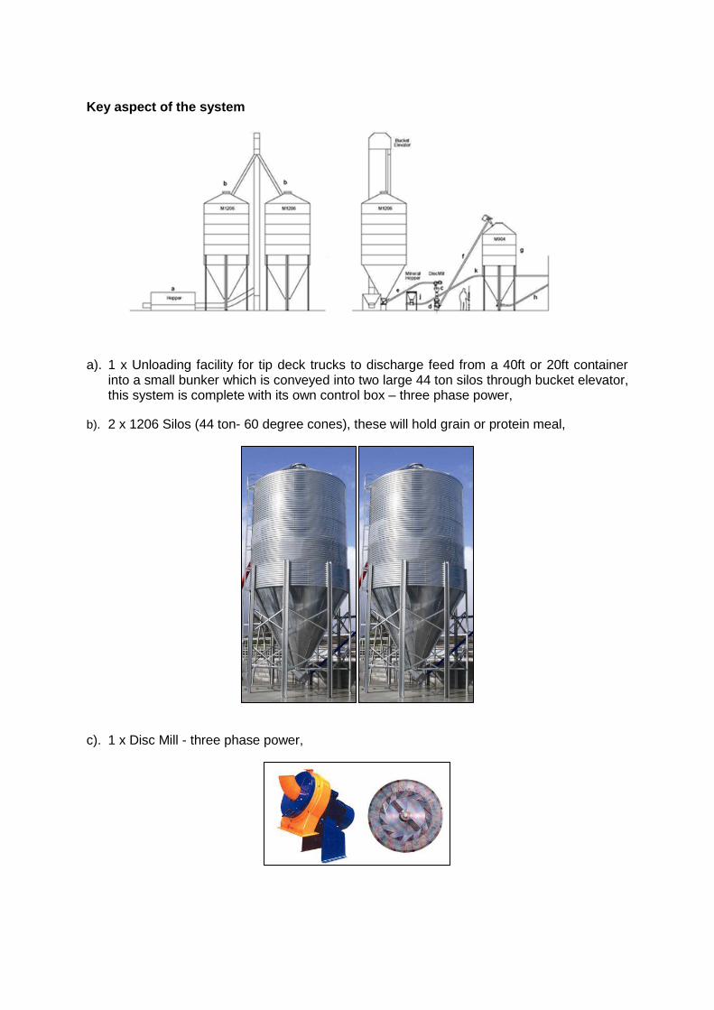
Key aspect of the system
a). 1 x Unloading facility for tip deck trucks to discharge feed from a 40ft or 20ft container into a small bunker which is conveyed into two large 44 ton silos through bucket elevator, this system is complete with its own control box – three phase power,
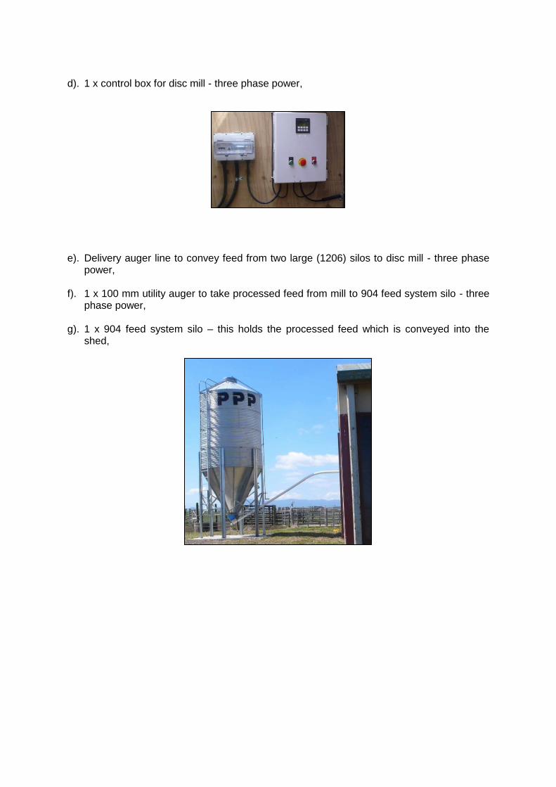
b). 2 x 1206 Silos (44 ton- 60 degree cones), these will hold grain or protein meal,
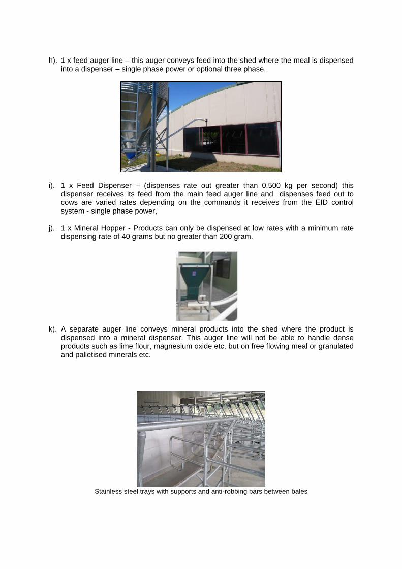
c). 1 x Disc Mill - three phase power,
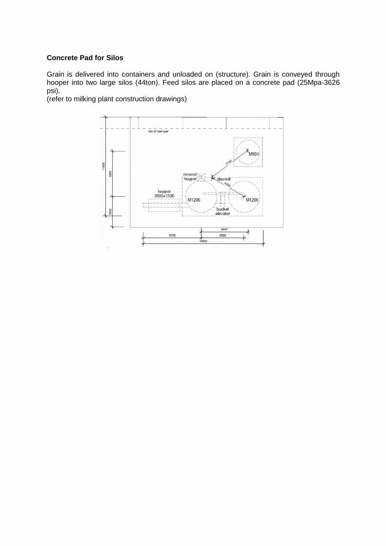
d). 1 x control box for disc mill - three phase power,
e). Delivery auger line to convey feed from two large (1206) silos to disc mill - three phase power,
f). 1 x 100 mm utility auger to take processed feed from mill to 904 feed system silo - three phase power,
g). 1 x 904 feed system silo – this holds the processed feed which is conveyed into the
shed,
h). 1 x feed auger line – this auger conveys feed into the shed where the meal is dispensed into a dispenser – single phase power or optional three phase,
i). 1 x Feed Dispenser – (dispenses rate out greater than 0.500 kg per second) this dispenser receives its feed from the main feed auger line and dispenses feed out to cows are varied rates depending on the commands it receives from the EID control system - single phase power,
j). 1 x Mineral Hopper - Products can only be dispensed at low rates with a minimum rate dispensing rate of 40 grams but no greater than 200 gram.
k). A separate auger line conveys mineral products into the shed where the product is
dispensed into a mineral dispenser. This auger line will not be able to handle dense products such as lime flour, magnesium oxide etc. but on free flowing meal or granulated and palletised minerals etc.
Stainless steel trays with supports and anti-robbing bars between bales
Concrete Pad for Silos Grain is delivered into containers and unloaded on (structure). Grain is conveyed through hooper into two large silos (44ton). Feed silos are placed on a concrete pad (25Mpa-3626 psi). (refer to milking plant construction drawings)
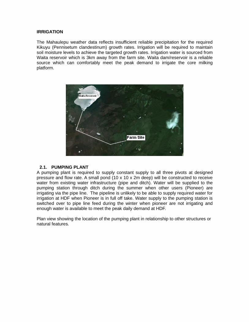
IRRIGATION The Mahaulepu weather data reflects insufficient reliable precipitation for the required Kikuyu (Pennisetum clandestinum) growth rates. Irrigation will be required to maintain soil moisture levels to achieve the targeted growth rates. Irrigation water is sourced from Waita reservoir which is 3km away from the farm site. Waita dam/reservoir is a reliable source which can comfortably meet the peak demand to irrigate the core milking platform.
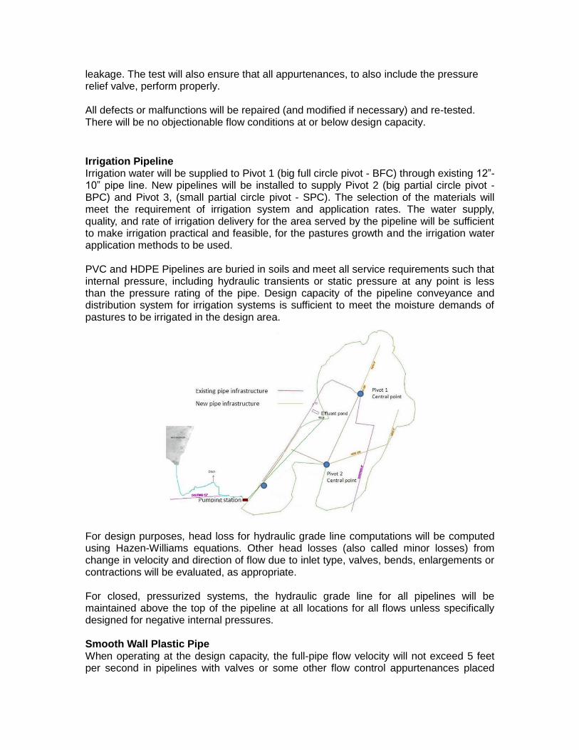
2.1. PUMPING PLANT A pumping plant is required to supply constant supply to all three pivots at designed pressure and flow rate. A small pond (10 x 10 x 2m deep) will be constructed to receive water from existing water infrastructure (pipe and ditch). Water will be supplied to the pumping station through ditch during the summer when other users (Pioneer) are irrigating via the pipe line. The pipeline is unlikely to be able to supply required water for irrigation at HDF when Pioneer is in full off take. Water supply to the pumping station is switched over to pipe line feed during the winter when pioneer are not irrigating and enough water is available to meet the peak daily demand at HDF. Plan view showing the location of the pumping plant in relationship to other structures or natural features.
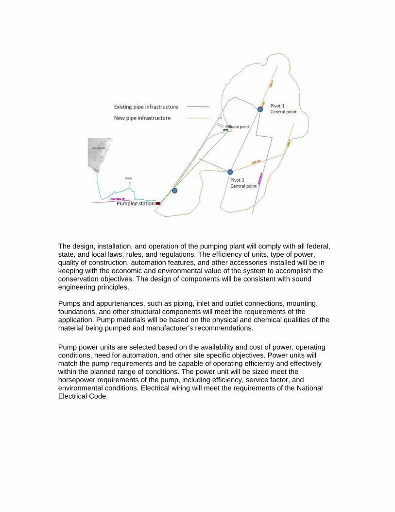
The design, installation, and operation of the pumping plant will comply with all federal, state, and local laws, rules, and regulations. The efficiency of units, type of power, quality of construction, automation features, and other accessories installed will be in keeping with the economic and environmental value of the system to accomplish the conservation objectives. The design of components will be consistent with sound engineering principles. Pumps and appurtenances, such as piping, inlet and outlet connections, mounting, foundations, and other structural components will meet the requirements of the application. Pump materials will be based on the physical and chemical qualities of the material being pumped and manufacturer's recommendations.
Pump power units are selected based on the availability and cost of power, operating conditions, need for automation, and other site specific objectives. Power units will match the pump requirements and be capable of operating efficiently and effectively within the planned range of conditions. The power unit will be sized meet the horsepower requirements of the pump, including efficiency, service factor, and environmental conditions. Electrical wiring will meet the requirements of the National Electrical Code.
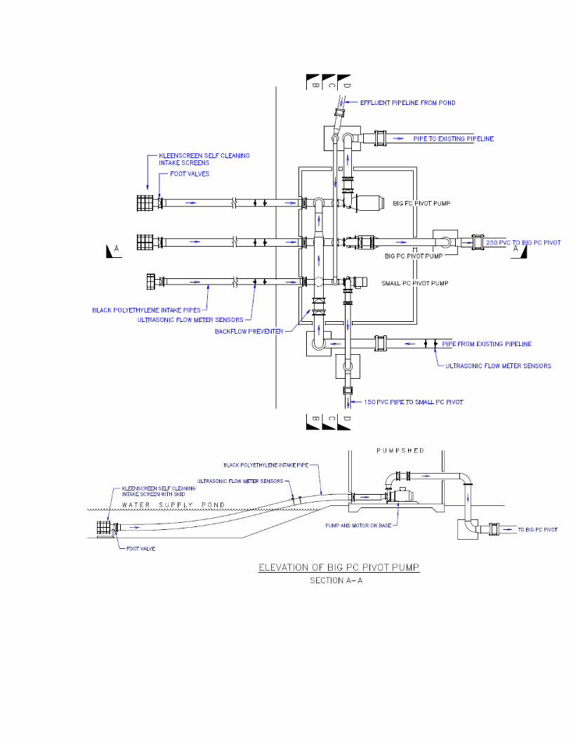
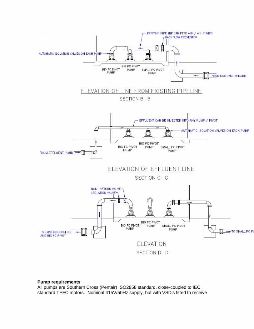
Pump requirements All pumps are Southern Cross (Pentair) ISO2858 standard, close-coupled to IEC standard TEFC motors. Nominal 415V/50Hz supply, but with VSD's fitted to receive
480V/60Hz. Pumps are fitted with VSD's to allow pressure variation on the pivots when they are at different heights and on the effluent transfer pump to allow different rates to be applied depending on the management requirements. The VSD handles pressure, motor overload and thermal protections. Pump for Pivot # 1 (BIG FC PIVOT PUMP) Design flow rate = 65L/s (235m³/h, 1,035gpm) Range of operating heads = 48-60m (72-90psi) Pump types = End suction centrifugal Horsepower requirement of the pumps = 45kW (60hp) Required power unit per pump = 55kW (75hp) Size of suction and discharge pipe = Pump suction flange - 5", Suction pipe 10", Pump discharge flange 4", discharge pipe 8" Description of appurtenances 9gate valves, check valves, pressure reducing valves, pressure gages, pipe connections, and other protective devices) = Wafer check valve, butterfly valve, pressure gauge, ultrasonic flow meter. Intake screen = Stainless steel, self-cleaning intake screen, 8" flange Backflow prevention devices = Foot valve and air gap above pond Pressure gauge = Fitted to discharge pipe, electronic gauge in VSD for pivot pressure. Pump for Pivot # 2 (BIG PC PIVOT PUMP) Design flow rate = 52L/s (187m³/h, 825gpm) Range of operating heads = 27-33m (40-50psi) Pump types = End suction centrifugal Horsepower requirement of the pumps 18kW (25hp) Required power unit per pump = 30kW (40hp) Size of suction and discharge pipe = Pump suction flange - 5", Suction pipe 10", Pump discharge flange 4", discharge pipe 8" Description of appurtenances 9gate valves, check valves, pressure reducing valves, pressure gages, pipe connections, and other protective devices) = Wafer check valve, butterfly valve, pressure gauge, ultrasonic flow meter Intake screen = Stainless steel, self-cleaning intake screen, 8" flange Backflow prevention devices = Foot valve and air gap above pond Pressure gauge = Fitted to discharge pipe, electronic gauge in VSD for pivot pressure Pump for Pivot # 3 (SMALL PC PIVOT PUMP) Design flow rate = 18L/s (65m³/h, 285gpm) Range of operating heads = 21-28m (30-40psi) Pump types = End suction centrifugal Horsepower requirement of the pumps = 6.5kW (8.5hp) Required power unit per pump = 7.5kW (10hp) Size of suction and discharge pipe = Pump suction flange - 4", Suction pipe 6", Pump discharge flange 2-1/2", discharge pipe 6" Description of appurtenances 9gate valves, check valves, pressure reducing valves, pressure gages, pipe connections, and other protective devices) = Wafer check valve, butterfly valve, pressure gauge, ultrasonic flow meter. Intake screen = Stainless steel, self-cleaning intake screen, 6" flange Backflow prevention devices = Foot valve and air gap above pond
Pressure gauge = Fitted to discharge pipe, electronic gauge in VSD for pivot pressure. A Variable Frequency Drive will be installed prior to installation and electric power provider will be informed. Variable frequency drive will follow the requirements of the electric power provider. The Variable Frequency Drive will be protected against overheating. The Variable Frequency Drive control panel will provide the read out display of flow rate or pressure. Suction and discharge pipes To prevent cavitation, suction and discharge pipes will be designed to account for suction lift, net positive suction head, pipe diameter and length, minor losses, temperature, and altitude. The size of suction and discharge pipes will be based on hydraulic analysis, operating costs, and compatibility with other system components. Appurtenances such as gate valves, check valves, pressure reducing valves, pressure gages, pipe connections, and other protective devices, will be included to meet the requirements of the application. Screens, filters, trash racks, or other devices will be installed as needed to prevent the intake of sand, gravel, debris, or other objectionable material into the pump. Intake screens will be designed according to applicable Federal and State guidelines, to avoid entrainment or trapping of aquatic organisms. Backflow prevention devices will be included according to Federal, State, and Local laws, to prevent contamination of water sources connected to the pumping plant. An appropriate high quality pressure gauge will be installed on the discharge of all pressurized systems. Pumps will be securely mounted on a solid concrete foundation. Foundations will be designed to safely support the loads imposed by the pumping plant and appurtenances. Sheet piling or other measures will be used, as required, to prevent piping beneath the foundation. The total area required for pumping station is 120 sq ft, provisions will be included for adequate ventilation and accessibility for equipment maintenance, repairs, or removal. Suction bays or sumps will be designed to prevent the introduction of air at the intake. The discharge bay or the connection to the distribution system will meet all hydraulic and structural requirements. Structures and equipment will be designed to provide adequate safety features to protect operators, workers, and the public from potential injury. Drive shaft covers will be installed on all exposed rotating shafts. Provisions for the connection of flow and pressure measurement devices will be included in power plant system design. Replacement pumping plants will have lower total emissions of oxides of nitrogen and fine particulate matter, compared to the unit being replaced. New, replacement, or retrofitted pumping equipment will utilize a non-combustion power source, or cleaner-burning technologies or fuels. Protective sensors will be included to detect low or stopped flow, or pressures that are too high or too low.
The visual appearance of buildings or structures associated with the pumping plant will be compatible with the surrounding environment. Consideration will be given to minimizing the effects of noise generated by the pumping plant.
The pump will achieve an efficiency of at least 75%. Electric motor will achieve an efficiency of at least 90%
The work will consist of furnishing labour, equipment, and materials for construction to the lines, grades, and elevations as shown on the drawings, as staked in the field, or both. Construction will be in accordance with the construction drawings and these specifications. All components will conform to the approved design and drawings and the manufacturer’s recommendations. Proper installation of the foot valve, suction pipe, control valves, pressure relief valve, outlet pipeline, and all connections will be insured according to the design drawings and the supplier/manufacturer’s requirements to withstand the maximum expected vacuum/pressure without damage or leakage. Pumping plant components include: Electrical panel - 3 phase supply fully enclosed in metal cabinet Load capacity- 110 KW Starting and shut-off switches, protective covers, and necessary safety overload shut-off devices. The installation and all components will conform to the manufacturer’s recommendations and meet all applicable electrical codes. All other elements necessary for successful operation of the pumping plant such as pressure gauges, sump, measuring device, flow detection device, alternative power sources, brackets, and bracing will be installed as per the drawings and manufacturer/supplier requirements. Construction operations will be carried out in such a manner and sequence that erosion and air and water pollution are minimized and held within legal limits. All trees, stumps, roots, brush, weeds, large rocks, and other objectionable material will be removed to allow an adequate and safe work area for pumping plant installation. To prevent differential settlement and to ensure a stable foundation, backfill adjacent to the pumping plant and appurtenances is critical and will be to the approximate same density as adjacent undisturbed earth. Area surrounding the pumping plant will be graded to provide free drainage of surface water. All disturbed areas will be gravelled, paved, or otherwise protected to control erosion. All construction will be performed in a workmanlike manner, and the job site will have a neat appearance when finished. As determined by procedures developed by the system designer, the system will be thoroughly and completely tested at the design pressure and capacity for strength and
leakage. The test will also ensure that all appurtenances, to also include the pressure relief valve, perform properly. All defects or malfunctions will be repaired (and modified if necessary) and re-tested. There will be no objectionable flow conditions at or below design capacity.
Irrigation Pipeline Irrigation water will be supplied to Pivot 1 (big full circle pivot - BFC) through existing 12”-10” pipe line. New pipelines will be installed to supply Pivot 2 (big partial circle pivot - BPC) and Pivot 3, (small partial circle pivot - SPC). The selection of the materials will meet the requirement of irrigation system and application rates. The water supply, quality, and rate of irrigation delivery for the area served by the pipeline will be sufficient to make irrigation practical and feasible, for the pastures growth and the irrigation water application methods to be used. PVC and HDPE Pipelines are buried in soils and meet all service requirements such that internal pressure, including hydraulic transients or static pressure at any point is less than the pressure rating of the pipe. Design capacity of the pipeline conveyance and distribution system for irrigation systems is sufficient to meet the moisture demands of pastures to be irrigated in the design area.
For design purposes, head loss for hydraulic grade line computations will be computed using Hazen-Williams equations. Other head losses (also called minor losses) from change in velocity and direction of flow due to inlet type, valves, bends, enlargements or contractions will be evaluated, as appropriate. For closed, pressurized systems, the hydraulic grade line for all pipelines will be maintained above the top of the pipeline at all locations for all flows unless specifically designed for negative internal pressures. Smooth Wall Plastic Pipe When operating at the design capacity, the full-pipe flow velocity will not exceed 5 feet per second in pipelines with valves or some other flow control appurtenances placed
within the pipeline or at the downstream end. The working pressure at all locations and under all anticipated flow conditions will not exceed 72 percent of the pressure rating of the pipe. Irrigation pipelines will be supported, where needed, to provide stability against external and internal forces. All connections will be designed and constructed to withstand the pipeline working pressure without leakage and leave the inside of the pipeline free of any obstruction that would reduce capacity.
Permissible joint deflection will be obtained from the manufacturer for the joint type and pipe material used.
For sloping steel pipe, expansion joints will be placed adjacent to and downhill from anchors or thrust blocks.
For welded pipe joints, expansion joints will be installed, as needed, to limit pipeline stresses to the allowable values.
For suspended pipelines, joints will be designed for pipe loading including the water in the pipe, wind, and the effects of thermal expansion and contraction.
Joints and connections for metal pipes should be of similar materials whenever possible. If dissimilar materials are used, the joints or connections will be protected against galvanic corrosion. Buried pipe will be installed at sufficient depth below the ground surface to provide protection from hazards imposed by traffic loads, farming operations, freezing temperatures, or soil cracking, as applicable. Pipelines will have sufficient strength to withstand all external loads on the pipe for the given installation conditions. Appropriate live loads will be used for the anticipated traffic conditions. If site conditions preclude adequate cover, extra fill will be placed over the pipeline to provide the minimum depth of cover. The top width of the fill will be no less than 2 feet wider than the trench and the side slopes no steeper than 6:1. Where it is not possible to achieve sufficient cover or sufficient strength, a carrier (encasement) pipe or other mechanical measures will be used. Pressure reduction will be incorporated in circumstances such as head gain exceeding pressure loss by a significant amount, excessive line pressure for the type of irrigation system supplied, or excessive static pressures.
Inlets
Inlets will be of adequate size to ensure design flow capacity without excessive head losses. Provision will be made to prevent the inflow of trash or other materials into the pipeline if these materials would be detrimental to the pipe capacity or performance of the irrigation application system.
A check valve will be installed between the pump discharge and the pipeline if detrimental backflow may occur. Check valves can cause extreme internal pressures, due to water hammer; if they close too fast as flow reversal occurs. Approved backflow prevention chemigation valves devices will be used on all pipelines in which fertilizer, liquid manure, waste water, pesticides, acids, or other chemicals are added to the water supply and where back flow may contaminate the source water supply or groundwater.
Pressure ratings of valves and other appurtenances will equal or exceed the pipeline working pressure. When lever operated valves are used, an analysis will be performed to evaluate potential surge/water hammer assuming an instantaneous valve closure. The inside diameter of the closed stand will be equal to or greater than that of the pipeline for at least 1 foot above the top of the uppermost inlet of outlet pipe. To facilitate attaching the pressure-relief valve and the air-and-vacuum valve, the stand may be capped at this point, or if additional height is required, the stand may be extended to the desired elevation by using the same inside diameter or a reduced cross section. If a reduced section is used, the cross-sectional area will be such that it would produce an average velocity of no more than 10 feet per second if the entire flow were discharged though it. If the discharge pipe is “dog-legged” below ground, the stand will extend at least 1 foot above the highest part of the pump discharge pipe.
An acceptable alternative design for stands requiring no vertical inlet offset (when inlet velocity is less than three times that of the outlet pipeline) will be:
Construct the dog-leg section of the pump discharge pipe with the same nominal pipe diameter as that of the pipeline.
Install the pressure-relief valve and the air-and-vacuum valve on top of the upper horizontal section of the dog-leg.
Pressure-relief and air-and-vacuum valves will be installed on stands with the nominal size pipe required to fit the valves’ threaded inlets.
COMB valves have the combined function of all three valves (CAV, VR, and AVR) in one body. COMB valves may be used for any of the conditions in which a CAV, VR, or AVR is required.
If needed to provide positive means for air escape during filling and air entry while emptying a pipeline, an AVR, VR, or COMB valve will be installed at all summits, upstream and downstream of all in-line valves as needed, at the entrance, and at the downstream end(s) of the pipelines. Such valves are needed at these locations if the pipeline is closed to the atmosphere. However, they may not be needed if other features of the pipe system, such as permanently located sprinkler nozzles or other unclosed service outlets, adequately vent the particular location during filling and emptying operations. The use of these system features must be analyzed for air flow rate and the proper use of such features described in the Operation and Maintenance plan. High points in the pipeline require a CAV unless an outlet is located at that point.
In addition to the locations described above, an AVR or COMB valve will be located at changes of grade in downward direction of flow in excess of 10 degrees (approximately 18% slope), to ensure adequate air release during filling. On long pipelines, additional AVR or COMB valves may be required to adequately vent the pipe during filling.
For air release, the AVR or COMB valve will be sized to exhaust air from the pipeline at the rate needed to prevent operational problems with the pipeline, while maintaining the proper operation of the valve. For design purposes, the exhaust pressure differential will be limited to 2 psi.
Long pipelines may require CAV valves spaced in the range of 1,200 to 3,000 feet. Without site specific analysis, a spacing of ¼ mile is recommended.
For vacuum relief, the AVR, VR, or COMB valves will be sized for air entry into the pipeline, ensuring the pipeline does not collapse due to vacuum created during drainage
of the pipeline. For design purposes, the vacuum pressure differential will be limited to 5 psi, or the computed pipe collapse pressure, whichever is smaller.
If the required vacuum relief orifice diameter is significantly larger than the required air release orifice diameter, separate valves may be required to help eliminate excessive water hammer caused when the air is released too fast from the pipeline.
CAV or COMB valves will be used as needed to permit air to escape while the line is at working pressure. Small orifices of these valve types will be sized according to the design working pressure and venting requirements recommended by the valve manufacturer.
The location of the CAV or COMB valves will be sufficient distance downstream from the introduction of air into the system (under pressure conditions) to allow the air to be collected at the top of the pipe. Under some circumstances (e.g., pumped system with low pressure or velocity) consideration should be given to installing vent chambers for CAV or COMB valves. The vent chamber should be constructed according to the requirements under the second criterion in the “Vents” section of this standard.
Air vent size will be based on pipeline size, pipe slope towards drains, and filling requirements. For pipeline size up to 3-inch diameter, 1/2-inch diameter valves are generally adequate for filling operations, or preventing a vacuum from forming during emptying.
For the corresponding pipe material below, the following size air valves will be used:
For Plastic ≤ 50 psi - 0.22 x pipe diameter
For Plastic > 50 psi - 0.10 x pipe diameter
For Metal - 0.125 x pipe diameter
For Concrete - 0.125 x pipe diameter
Manufacturers of air valves marketed for use under this standard will provide dimensional data or a capacity table based on performance tests, which will be the basis for selection and acceptance of these valves.
Outlets
Outlets will have adequate capacity and pressure rating to deliver the required flow to the centre pivot at required operating pressure. Outlets will be designed to minimize physical damage, or deterioration due to exposure.
Filling
The pipe system will have a means of controlling the filling of the pipeline to prevent entrapped air and excessive transient pressures.
Filling velocities greater than 1 foot per second in a closed-to-the-atmosphere pipe system (i.e., all outlets closed) requires special evaluation and provisions to remove entrapped air and prevent transient pressures.
If filling at a low flow rate is not possible, the system will be open to the atmosphere (outlets open) prior to pressurizing. The valves to the supplied irrigation system components (gated pipe, wheel line, pivot, etc.) should be opened to release entrapped air and minimize transient pressures in the system. The system will be designed for air removal and excessive transient pressures that may develop at higher filling rates.
Safe Discharge of Water
Provisions will be made for water being discharged from valves, especially air valves and pressure relief valves, such valves will be located such that flows are directed away from system operators, electrical equipment and other control valves or hook-ups.
Thrust Control
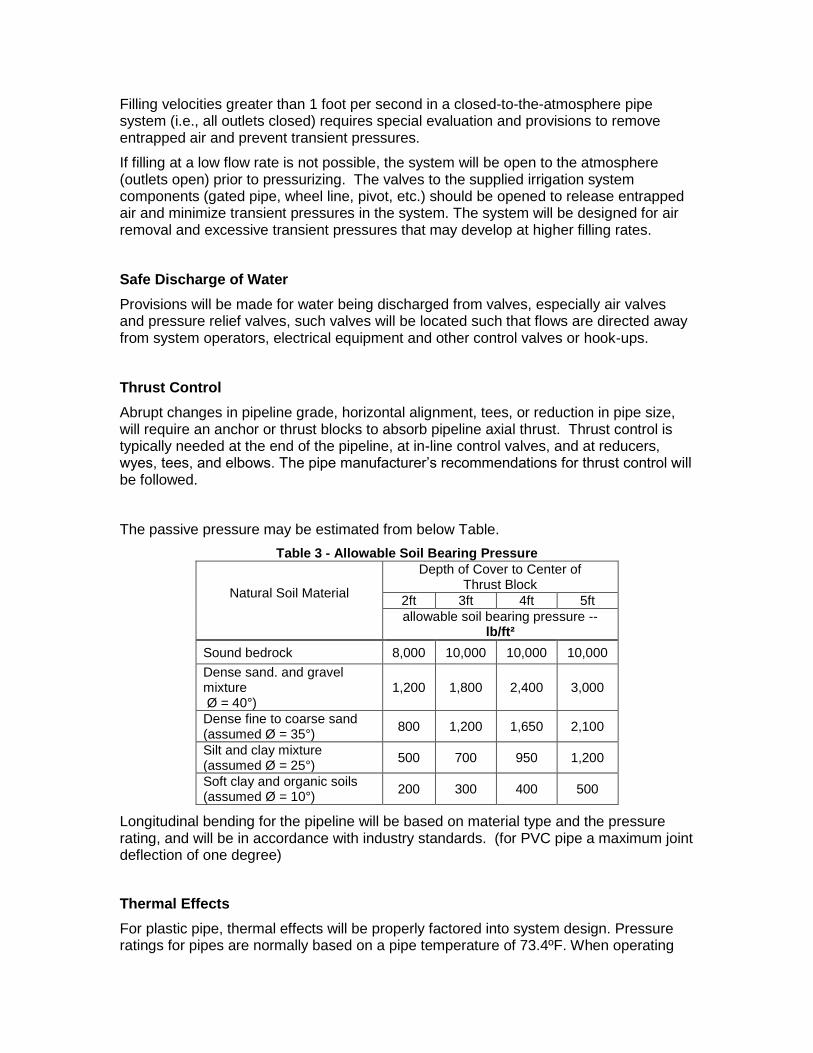
Abrupt changes in pipeline grade, horizontal alignment, tees, or reduction in pipe size, will require an anchor or thrust blocks to absorb pipeline axial thrust. Thrust control is typically needed at the end of the pipeline, at in-line control valves, and at reducers, wyes, tees, and elbows. The pipe manufacturer’s recommendations for thrust control will be followed.
The passive pressure may be estimated from below Table.
Table 3 - Allowable Soil Bearing Pressure
Natural Soil Material
Depth of Cover to Center of Thrust Block
2ft 3ft 4ft 5ft
allowable soil bearing pressure --lb/ft²
Sound bedrock 8,000 10,000 10,000 10,000
Dense sand. and gravel mixture Ø = 40°)
1,200 1,800 2,400 3,000
Dense fine to coarse sand (assumed Ø = 35°)
800 1,200 1,650 2,100
Silt and clay mixture (assumed Ø = 25°)
500 700 950 1,200
Soft clay and organic soils (assumed Ø = 10°)
200 300 400 500
Longitudinal bending for the pipeline will be based on material type and the pressure rating, and will be in accordance with industry standards. (for PVC pipe a maximum joint deflection of one degree)
Thermal Effects
For plastic pipe, thermal effects will be properly factored into system design. Pressure ratings for pipes are normally based on a pipe temperature of 73.4ºF. When operating
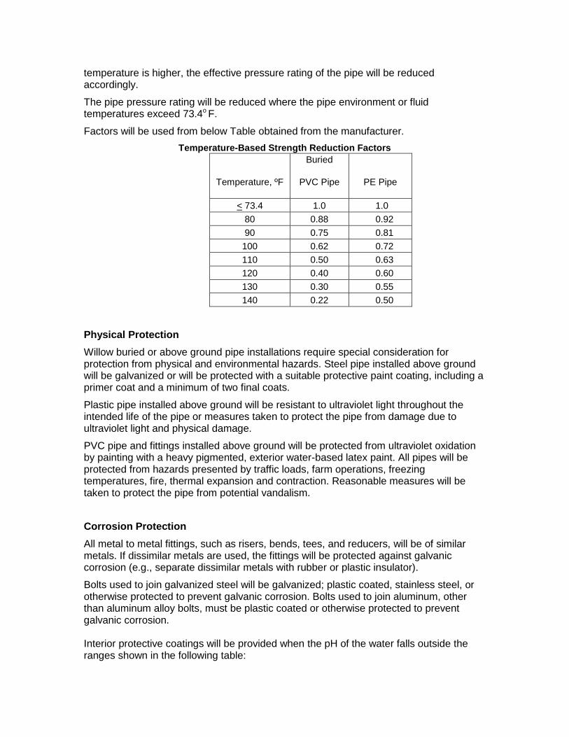
temperature is higher, the effective pressure rating of the pipe will be reduced accordingly.
The pipe pressure rating will be reduced where the pipe environment or fluid temperatures exceed 73.4o F.
Factors will be used from below Table obtained from the manufacturer.
Temperature-Based Strength Reduction Factors
Temperature, ºF
Buried
PVC Pipe
PE Pipe
< 73.4 1.0 1.0
80 0.88 0.92
90 0.75 0.81
100 0.62 0.72
110 0.50 0.63
120 0.40 0.60
130 0.30 0.55
140 0.22 0.50
Physical Protection
Willow buried or above ground pipe installations require special consideration for protection from physical and environmental hazards. Steel pipe installed above ground will be galvanized or will be protected with a suitable protective paint coating, including a primer coat and a minimum of two final coats.
Plastic pipe installed above ground will be resistant to ultraviolet light throughout the intended life of the pipe or measures taken to protect the pipe from damage due to ultraviolet light and physical damage.
PVC pipe and fittings installed above ground will be protected from ultraviolet oxidation by painting with a heavy pigmented, exterior water-based latex paint. All pipes will be protected from hazards presented by traffic loads, farm operations, freezing temperatures, fire, thermal expansion and contraction. Reasonable measures will be taken to protect the pipe from potential vandalism.
Corrosion Protection
All metal to metal fittings, such as risers, bends, tees, and reducers, will be of similar metals. If dissimilar metals are used, the fittings will be protected against galvanic corrosion (e.g., separate dissimilar metals with rubber or plastic insulator).
Bolts used to join galvanized steel will be galvanized; plastic coated, stainless steel, or otherwise protected to prevent galvanic corrosion. Bolts used to join aluminum, other than aluminum alloy bolts, must be plastic coated or otherwise protected to prevent galvanic corrosion. Interior protective coatings will be provided when the pH of the water falls outside the ranges shown in the following table:
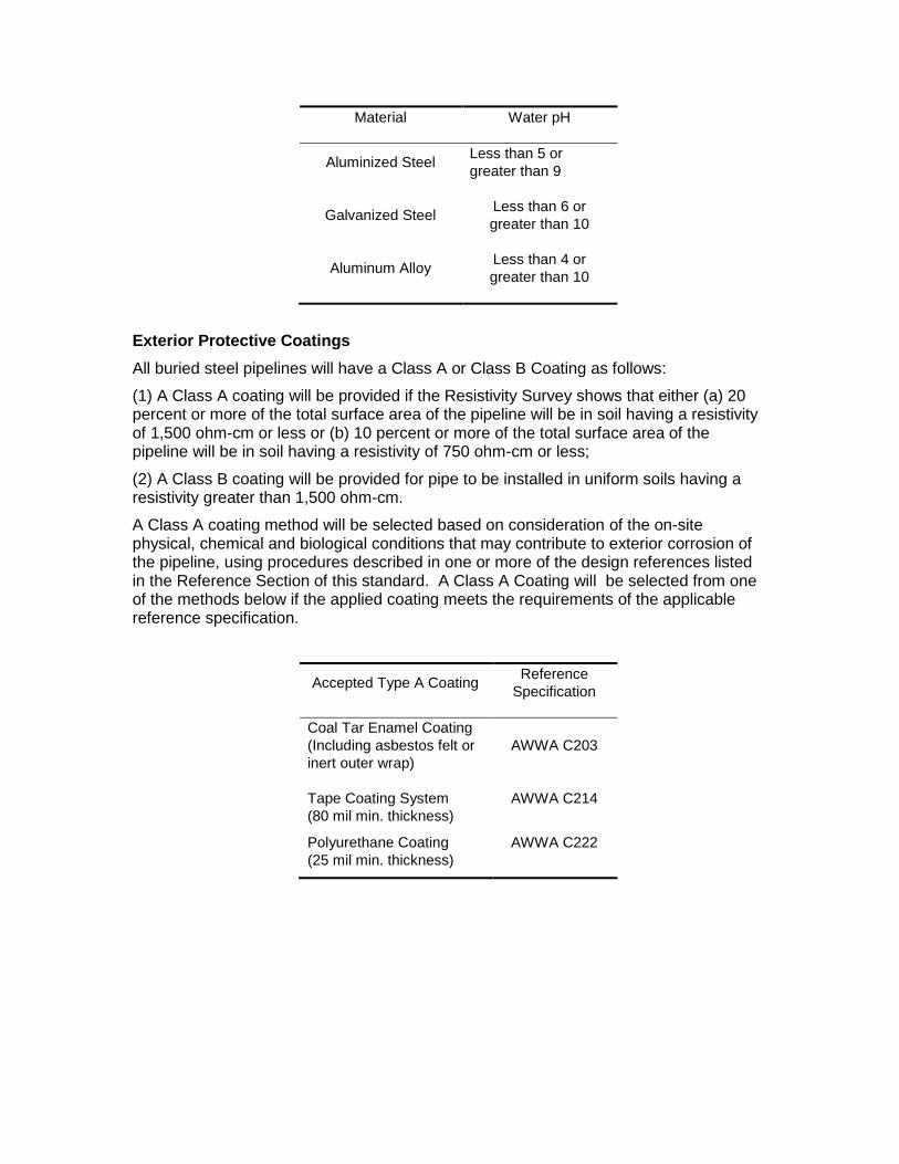
Material Water pH
Aluminized Steel Less than 5 or
greater than 9
Galvanized Steel Less than 6 or
greater than 10
Aluminum Alloy Less than 4 or
greater than 10
Exterior Protective Coatings
All buried steel pipelines will have a Class A or Class B Coating as follows:
(1) A Class A coating will be provided if the Resistivity Survey shows that either (a) 20 percent or more of the total surface area of the pipeline will be in soil having a resistivity of 1,500 ohm-cm or less or (b) 10 percent or more of the total surface area of the pipeline will be in soil having a resistivity of 750 ohm-cm or less;
(2) A Class B coating will be provided for pipe to be installed in uniform soils having a resistivity greater than 1,500 ohm-cm.
A Class A coating method will be selected based on consideration of the on-site physical, chemical and biological conditions that may contribute to exterior corrosion of the pipeline, using procedures described in one or more of the design references listed in the Reference Section of this standard. A Class A Coating will be selected from one of the methods below if the applied coating meets the requirements of the applicable reference specification.
Accepted Type A Coating Reference
Specification
Coal Tar Enamel Coating
(Including asbestos felt or
inert outer wrap)
AWWA C203
Tape Coating System
(80 mil min. thickness)
AWWA C214
Polyurethane Coating
(25 mil min. thickness)
AWWA C222
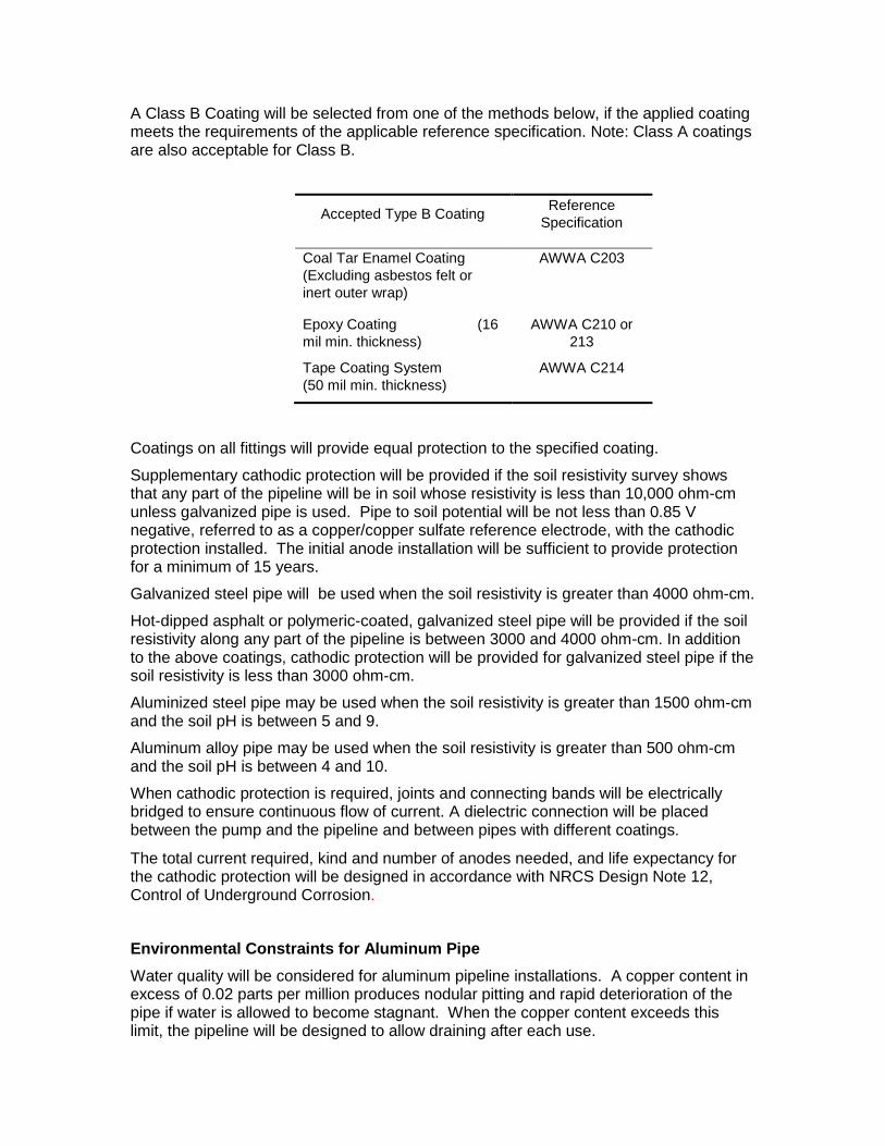
A Class B Coating will be selected from one of the methods below, if the applied coating meets the requirements of the applicable reference specification. Note: Class A coatings are also acceptable for Class B.
Accepted Type B Coating Reference
Specification
Coal Tar Enamel Coating
(Excluding asbestos felt or
inert outer wrap)
AWWA C203
Epoxy Coating (16
mil min. thickness)
AWWA C210 or
213
Tape Coating System
(50 mil min. thickness)
AWWA C214
Coatings on all fittings will provide equal protection to the specified coating.
Supplementary cathodic protection will be provided if the soil resistivity survey shows that any part of the pipeline will be in soil whose resistivity is less than 10,000 ohm-cm unless galvanized pipe is used. Pipe to soil potential will be not less than 0.85 V negative, referred to as a copper/copper sulfate reference electrode, with the cathodic protection installed. The initial anode installation will be sufficient to provide protection for a minimum of 15 years.
Galvanized steel pipe will be used when the soil resistivity is greater than 4000 ohm-cm.
Hot-dipped asphalt or polymeric-coated, galvanized steel pipe will be provided if the soil resistivity along any part of the pipeline is between 3000 and 4000 ohm-cm. In addition to the above coatings, cathodic protection will be provided for galvanized steel pipe if the soil resistivity is less than 3000 ohm-cm.
Aluminized steel pipe may be used when the soil resistivity is greater than 1500 ohm-cm and the soil pH is between 5 and 9.
Aluminum alloy pipe may be used when the soil resistivity is greater than 500 ohm-cm and the soil pH is between 4 and 10.
When cathodic protection is required, joints and connecting bands will be electrically bridged to ensure continuous flow of current. A dielectric connection will be placed between the pump and the pipeline and between pipes with different coatings.
The total current required, kind and number of anodes needed, and life expectancy for the cathodic protection will be designed in accordance with NRCS Design Note 12, Control of Underground Corrosion.
Environmental Constraints for Aluminum Pipe
Water quality will be considered for aluminum pipeline installations. A copper content in excess of 0.02 parts per million produces nodular pitting and rapid deterioration of the pipe if water is allowed to become stagnant. When the copper content exceeds this limit, the pipeline will be designed to allow draining after each use.

Protection from corrosion will be provided for aluminum pipe installed in contact with concrete.
Pipelines installed below the ground surface should have a soil plan describing soil reconstruction of disturbed soil during and after pipeline installation so original soil productivity is restored after pipeline installation. Appropriate vegetation should be established to stabilize disturbed areas that will not be cropped.
Pipe and fittings materials will meet the minimum cell classification and material designation as stated in Table 1. The pipe will be matric sized and rated and meet the applicable ISO standards comparable to ASTMA standards. listed in Table 2. Except for corrugated PE, all pipes will be pressure-rated for water. ABS pipe will be of solid wall construction. Pipe will be as uniform as commercially practicable in color, opaqueness, density, and other specified properties. It will be free of visible cracks, holes, foreign inclusions, sunburn, bleaching, or other defects. The pipe dimensions and ratings will be matric standard that is AS/NZS 4130. The wall thickness for all pipes installed under this standard, regardless of pressure rating or type, will not be less than 0.060 inches. All fittings will meet or exceed the same strength, pressure, and dimension requirements as those of the pipe and will be made of material that is recommended for use with the pipe. Joints and fittings will meet the applicable ISO standards comparable to ASTM specification and will be used and installed according to the recommendations of the manufacturer. All pipe fittings will meet the standard AS/NZS 4129. Solvent for solvent cement joints will conform to ASTM specifications D-2564 for PVC pipe and fittings and D-2235 for ABS pipe and fittings. Fittings or belled ends for solvent cement joints will have tapered sockets with socket lengths as per ASTM D2672. Sleeves for clamp-type joints will provide a minimum of 4 inches overlap between the sleeve and the pipe or fitting.
Table 1 - Material Requirements Material
Cell Class Allowable Material Designation
Applicable Material Specification
Polyvinyl Chloride 12454 PVC1120 ASTM D1784
PVC1220 14333 PVC2120 Polyethylene 345464C or greater PE3408 or greater ASTM D3350
ASTM F2306 (corrugated PE)
Acrylonitrile-Butadiene-Styrene
20643 or greater ABS1210 or greater ASTM D3965

Rubber gasket joints Rubber gasket joints will conform to ASTM Specification D3139 for pressure pipe or D3212 for corrugated PE pipe. All rubber gaskets will conform to ASTM F477. Gasket lubricant will be suitable for use in water transmission applications. The gasket will be the sole element depended upon to make the joint flexible and water tight. All surfaces of the joint upon or against which the gasket may bear, will be smooth, free of cracks, fractures, or imperfections that could adversely affect the integrity of the joint. Markings Fitting markings will include, as a minimum, the following information:
Manufacturer’s name or trademark
Nominal size
Pipe Schedule/pressure class/rating for water at 73 degrees F
Materials name and designation (PVC1120, PE3408, etc.)
Recognized standard to which fitting is designed and manufactured
Pipe markings will be repeated at a minimum interval of 5 ft along the pipe and will include, in addition to fitting marking requirements, the following information:
Specific production code including month and year
Outside diameter base/system (IPS, PIP, etc.) INSTALLATION Construction activities will follow all OSHA standards and regulations. All work will be neat and of a professional quality, as determined by the engineer. Site preparation (mobilization and demobilization, clearing and grubbing, structure removal, pollution control, and water for construction) will follow NRCS PI Supplemental Construction Specifications or others as appropriate. If pipe is stored outside for more than 15 days, it will be covered by a durable, light-colored, opaque material, and vented to prevent heat buildup. Avoid awkward placement of pipe that could affect pipe integrity and strength. Polyethylene plastic pipe, PE-3408 or better, up to 4-inch diameter, may be laid on the ground surface at locations where minimal hazards are imposed by fire, farm operations, traffic, vandalism, or theft. Snaking the pipe is necessary for surface pipes and an additional minimum 4% must be added to the length to accommodate the expansion and contraction. Surface pipe laid on steep slopes will be anchored to control creep and resulting added stresses at intervals of no less than 200 feet. At vehicle crossings, burial, encasement of pipe, or other approved methods will be used. Pipes are installed at sufficient depth below the ground surface to provide protection from hazards imposed by traffic crossings, farming operations, freezing temperatures, or soil cracking.
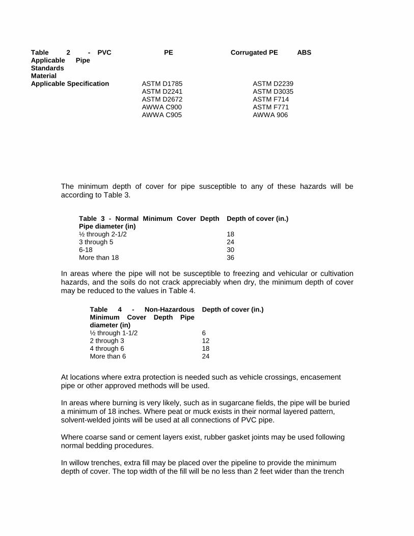
Table 2 - Applicable Pipe Standards Material
PVC PE Corrugated PE ABS
Applicable Specification ASTM D1785 ASTM D2241 ASTM D2672 AWWA C900 AWWA C905
ASTM D2239 ASTM D3035 ASTM F714 ASTM F771 AWWA 906
The minimum depth of cover for pipe susceptible to any of these hazards will be according to Table 3.
Table 3 - Normal Minimum Cover Depth Pipe diameter (in)
Depth of cover (in.)
½ through 2-1/2 18 3 through 5 24 6-18 30 More than 18 36
In areas where the pipe will not be susceptible to freezing and vehicular or cultivation hazards, and the soils do not crack appreciably when dry, the minimum depth of cover may be reduced to the values in Table 4.
At locations where extra protection is needed such as vehicle crossings, encasement pipe or other approved methods will be used. In areas where burning is very likely, such as in sugarcane fields, the pipe will be buried a minimum of 18 inches. Where peat or muck exists in their normal layered pattern, solvent-welded joints will be used at all connections of PVC pipe. Where coarse sand or cement layers exist, rubber gasket joints may be used following normal bedding procedures. In willow trenches, extra fill may be placed over the pipeline to provide the minimum depth of cover. The top width of the fill will be no less than 2 feet wider than the trench
Table 4 - Non-Hazardous Minimum Cover Depth Pipe diameter (in)
Depth of cover (in.)
½ through 1-1/2 6 2 through 3 12 4 through 6 18 More than 6 24
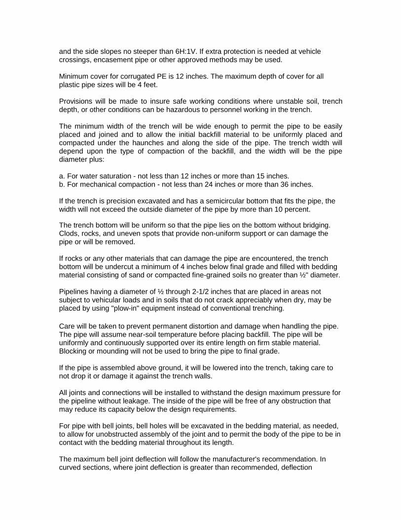
and the side slopes no steeper than 6H:1V. If extra protection is needed at vehicle crossings, encasement pipe or other approved methods may be used. Minimum cover for corrugated PE is 12 inches. The maximum depth of cover for all plastic pipe sizes will be 4 feet. Provisions will be made to insure safe working conditions where unstable soil, trench depth, or other conditions can be hazardous to personnel working in the trench. The minimum width of the trench will be wide enough to permit the pipe to be easily placed and joined and to allow the initial backfill material to be uniformly placed and compacted under the haunches and along the side of the pipe. The trench width will depend upon the type of compaction of the backfill, and the width will be the pipe diameter plus: a. For water saturation - not less than 12 inches or more than 15 inches. b. For mechanical compaction - not less than 24 inches or more than 36 inches. If the trench is precision excavated and has a semicircular bottom that fits the pipe, the width will not exceed the outside diameter of the pipe by more than 10 percent.
The trench bottom will be uniform so that the pipe lies on the bottom without bridging. Clods, rocks, and uneven spots that provide non-uniform support or can damage the pipe or will be removed. If rocks or any other materials that can damage the pipe are encountered, the trench bottom will be undercut a minimum of 4 inches below final grade and filled with bedding material consisting of sand or compacted fine-grained soils no greater than ½" diameter. Pipelines having a diameter of ½ through 2-1/2 inches that are placed in areas not subject to vehicular loads and in soils that do not crack appreciably when dry, may be placed by using "plow-in" equipment instead of conventional trenching.
Care will be taken to prevent permanent distortion and damage when handling the pipe. The pipe will assume near-soil temperature before placing backfill. The pipe will be uniformly and continuously supported over its entire length on firm stable material. Blocking or mounding will not be used to bring the pipe to final grade. If the pipe is assembled above ground, it will be lowered into the trench, taking care to not drop it or damage it against the trench walls. All joints and connections will be installed to withstand the design maximum pressure for the pipeline without leakage. The inside of the pipe will be free of any obstruction that may reduce its capacity below the design requirements. For pipe with bell joints, bell holes will be excavated in the bedding material, as needed, to allow for unobstructed assembly of the joint and to permit the body of the pipe to be in contact with the bedding material throughout its length. The maximum bell joint deflection will follow the manufacturer's recommendation. In curved sections, where joint deflection is greater than recommended, deflection

couplings or elbows will be used. A pipe section will never be bent, deformed, blocked, or braced to hold a curve. Allow heat fused and solvent-cemented joints to cool or cure for the minimum prescribed time before moving the pipe. Fittings made of steel or other metals susceptible to corrosion will be adequately protected by being wrapped with plastic tape or by being coated with a substance that has high corrosion-preventative qualities. If plastic tape is used, all surfaces will be thoroughly cleaned and coated with a primer compatible with the tape before wrapping. Thrust blocks will be used at all major changes in alignment, under valves, intersections, and dead ends. Thrust blocks must be formed against a solid hand-excavated trench wall undamaged by mechanical equipment. They will be constructed of concrete with a compressive strength of no less than 2000-psi and framed with wood or soil to restrain the freshly placed concrete. The space between the pipe and trench wall will be filled with concrete to the height of the outside diameter of the pipe or as specified by the manufacturer. Allow sufficient time for concrete to cure before burying the thrust block or pressurizing the pipe. Where pipes are located close to utilities, roads, right-of-ways, in locations where development is anticipated, or as indicated in the drawings, tracing wire will be installed. At a minimum, 14 gauge braided copper tracer wire will be secured to the top of the pipes and will surface at all ends and air vents. Wire will be continuous or have an approved splice. Tracer tape is acceptable. The pipeline will be tested for pressure strength, leakage, and proper functioning. The tests may be performed before backfilling or any time after the pipeline is ready for service. Partial backfills needed to hold the pipe in place during testing will be placed as specified in the Initial backfill section. The line will be slowly filled with water. Adequate provisions will be made for air release during filling operations, taking care to bleed all entrapped air. The pressure will be slowly built up to the maximum design working pressure of the system. While this pressure is maintained, all exposed pipe fittings, valves, hydrants, joints, appurtenances, and covered parts of the line will be examined for leaks. Any leaks will be repaired and the system retested. The pipeline will be tested to insure that it functions properly at design capacity. At or below design capacity, there will be no objectionable flow conditions. Initial backfill method may be hand, mechanical, or water packing, however, all special backfilling recommendations of the pipe manufacturer will be met. The initial backfill material will be soil or sand that is free from rocks or stones larger than 1 inch in diameter and earth clods greater than about 2 inches in diameter. Initial backfill will extend 6 inches above the top of the pipe. At the time of placement, the moisture content of the material will be such that the required degree of compaction can be obtained with the backfill method to be used. The material will be placed so that the pipe will not be displaced, deformed, or damaged.
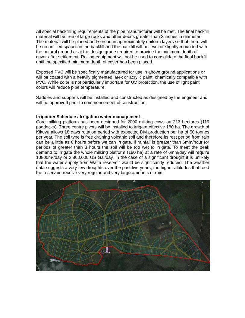
All special backfilling requirements of the pipe manufacturer will be met. The final backfill material will be free of large rocks and other debris greater than 3 inches in diameter. The material will be placed and spread in approximately uniform layers so that there will be no unfilled spaces in the backfill and the backfill will be level or slightly mounded with the natural ground or at the design grade required to provide the minimum depth of cover after settlement. Rolling equipment will not be used to consolidate the final backfill until the specified minimum depth of cover has been placed. Exposed PVC will be specifically manufactured for use in above ground applications or will be coated with a heavily pigmented latex or acrylic paint, chemically compatible with PVC. While color is not particularly important for UV protection, the use of light paint colors will reduce pipe temperature. Saddles and supports will be installed and constructed as designed by the engineer and will be approved prior to commencement of construction.
Irrigation Schedule / Irrigation water management Core milking platform has been designed for 2000 milking cows on 213 hectares (119 paddocks). Three centre pivots will be installed to irrigate effective 180 ha. The growth of Kikuyu allows 18 days rotation period with expected DM production per ha of 50 tonnes per year. The soil type is free draining volcanic soil and therefore its rest period from rain can be a little as 6 hours before we can irrigate, if rainfall is greater than 6mm/hour for periods of greater than 3 hours the soil will be too wet to irrigate. To meet the peak demand to irrigate the whole milking platform (180 ha) at a rate of 6mm/day will require 10800m³/day or 2,860,000 US Gal/day. In the case of a significant drought it is unlikely that the water supply from Waita reservoir would be significantly reduced. The weather data suggests a very few droughts over the past five years, the higher altitudes that feed the reservoir, receive very regular and very large amounts of rain.
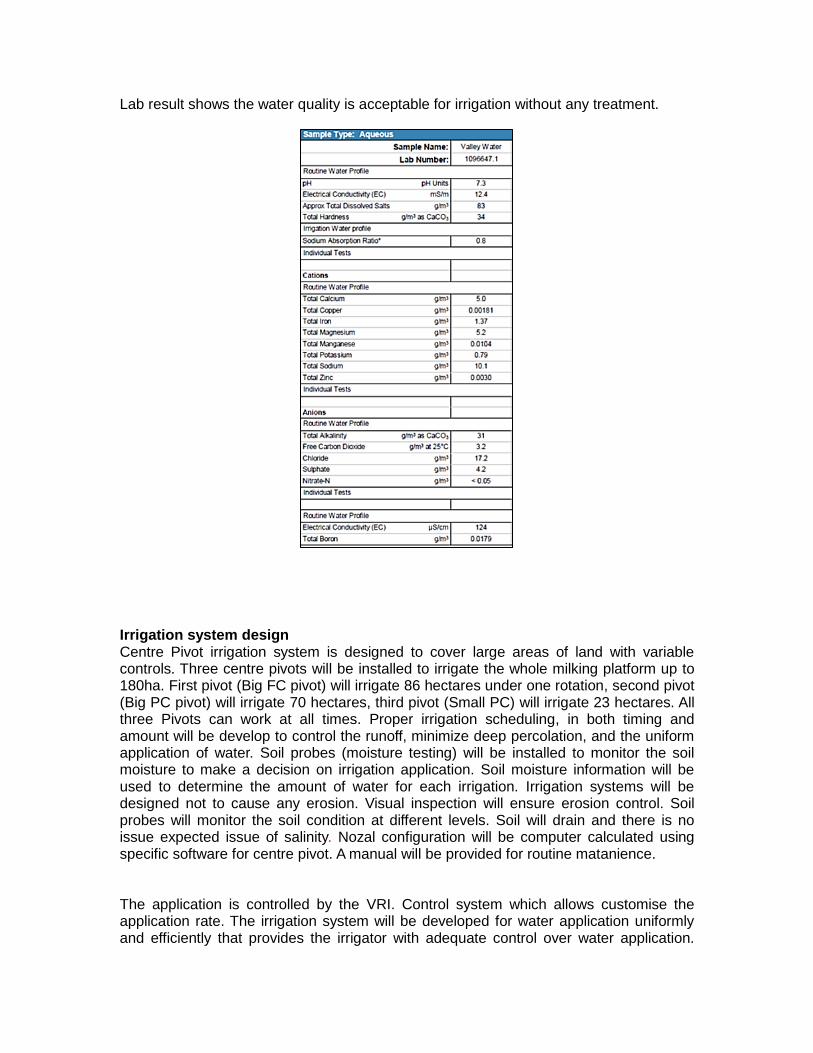
Lab result shows the water quality is acceptable for irrigation without any treatment.
Irrigation system design Centre Pivot irrigation system is designed to cover large areas of land with variable controls. Three centre pivots will be installed to irrigate the whole milking platform up to 180ha. First pivot (Big FC pivot) will irrigate 86 hectares under one rotation, second pivot (Big PC pivot) will irrigate 70 hectares, third pivot (Small PC) will irrigate 23 hectares. All three Pivots can work at all times. Proper irrigation scheduling, in both timing and amount will be develop to control the runoff, minimize deep percolation, and the uniform application of water. Soil probes (moisture testing) will be installed to monitor the soil moisture to make a decision on irrigation application. Soil moisture information will be used to determine the amount of water for each irrigation. Irrigation systems will be designed not to cause any erosion. Visual inspection will ensure erosion control. Soil probes will monitor the soil condition at different levels. Soil will drain and there is no issue expected issue of salinity. Nozal configuration will be computer calculated using specific software for centre pivot. A manual will be provided for routine matanience.
The application is controlled by the VRI. Control system which allows customise the application rate. The irrigation system will be developed for water application uniformly and efficiently that provides the irrigator with adequate control over water application.
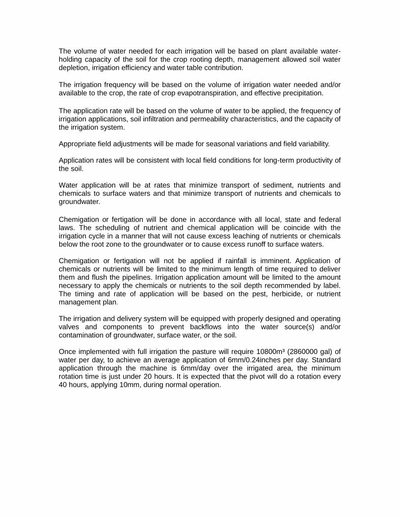
The volume of water needed for each irrigation will be based on plant available water-holding capacity of the soil for the crop rooting depth, management allowed soil water depletion, irrigation efficiency and water table contribution. The irrigation frequency will be based on the volume of irrigation water needed and/or available to the crop, the rate of crop evapotranspiration, and effective precipitation.
The application rate will be based on the volume of water to be applied, the frequency of irrigation applications, soil infiltration and permeability characteristics, and the capacity of the irrigation system. Appropriate field adjustments will be made for seasonal variations and field variability. Application rates will be consistent with local field conditions for long-term productivity of the soil. Water application will be at rates that minimize transport of sediment, nutrients and chemicals to surface waters and that minimize transport of nutrients and chemicals to groundwater.
Chemigation or fertigation will be done in accordance with all local, state and federal laws. The scheduling of nutrient and chemical application will be coincide with the irrigation cycle in a manner that will not cause excess leaching of nutrients or chemicals below the root zone to the groundwater or to cause excess runoff to surface waters. Chemigation or fertigation will not be applied if rainfall is imminent. Application of chemicals or nutrients will be limited to the minimum length of time required to deliver them and flush the pipelines. Irrigation application amount will be limited to the amount necessary to apply the chemicals or nutrients to the soil depth recommended by label. The timing and rate of application will be based on the pest, herbicide, or nutrient management plan. The irrigation and delivery system will be equipped with properly designed and operating valves and components to prevent backflows into the water source(s) and/or contamination of groundwater, surface water, or the soil. Once implemented with full irrigation the pasture will require 10800m³ (2860000 gal) of water per day, to achieve an average application of 6mm/0.24inches per day. Standard application through the machine is 6mm/day over the irrigated area, the minimum rotation time is just under 20 hours. It is expected that the pivot will do a rotation every 40 hours, applying 10mm, during normal operation.
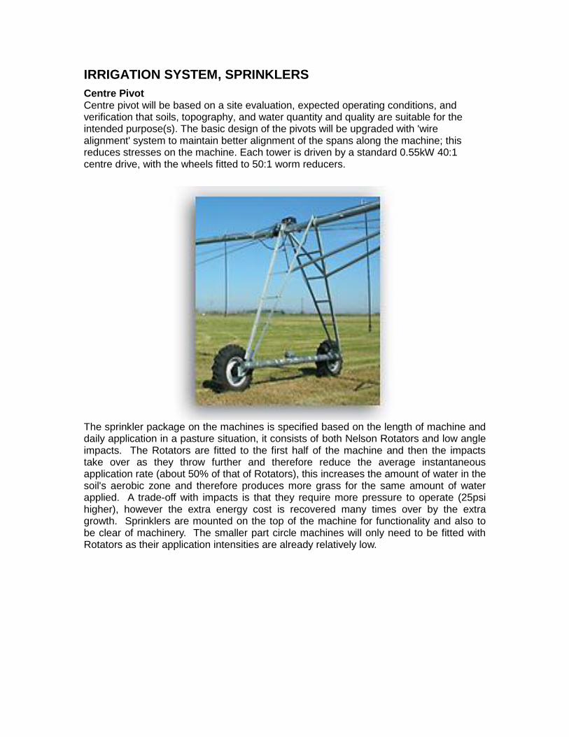
IRRIGATION SYSTEM, SPRINKLERS
Centre Pivot Centre pivot will be based on a site evaluation, expected operating conditions, and verification that soils, topography, and water quantity and quality are suitable for the intended purpose(s). The basic design of the pivots will be upgraded with 'wire alignment' system to maintain better alignment of the spans along the machine; this reduces stresses on the machine. Each tower is driven by a standard 0.55kW 40:1 centre drive, with the wheels fitted to 50:1 worm reducers.
The sprinkler package on the machines is specified based on the length of machine and daily application in a pasture situation, it consists of both Nelson Rotators and low angle impacts. The Rotators are fitted to the first half of the machine and then the impacts take over as they throw further and therefore reduce the average instantaneous application rate (about 50% of that of Rotators), this increases the amount of water in the soil's aerobic zone and therefore produces more grass for the same amount of water applied. A trade-off with impacts is that they require more pressure to operate (25psi higher), however the extra energy cost is recovered many times over by the extra growth. Sprinklers are mounted on the top of the machine for functionality and also to be clear of machinery. The smaller part circle machines will only need to be fitted with Rotators as their application intensities are already relatively low.
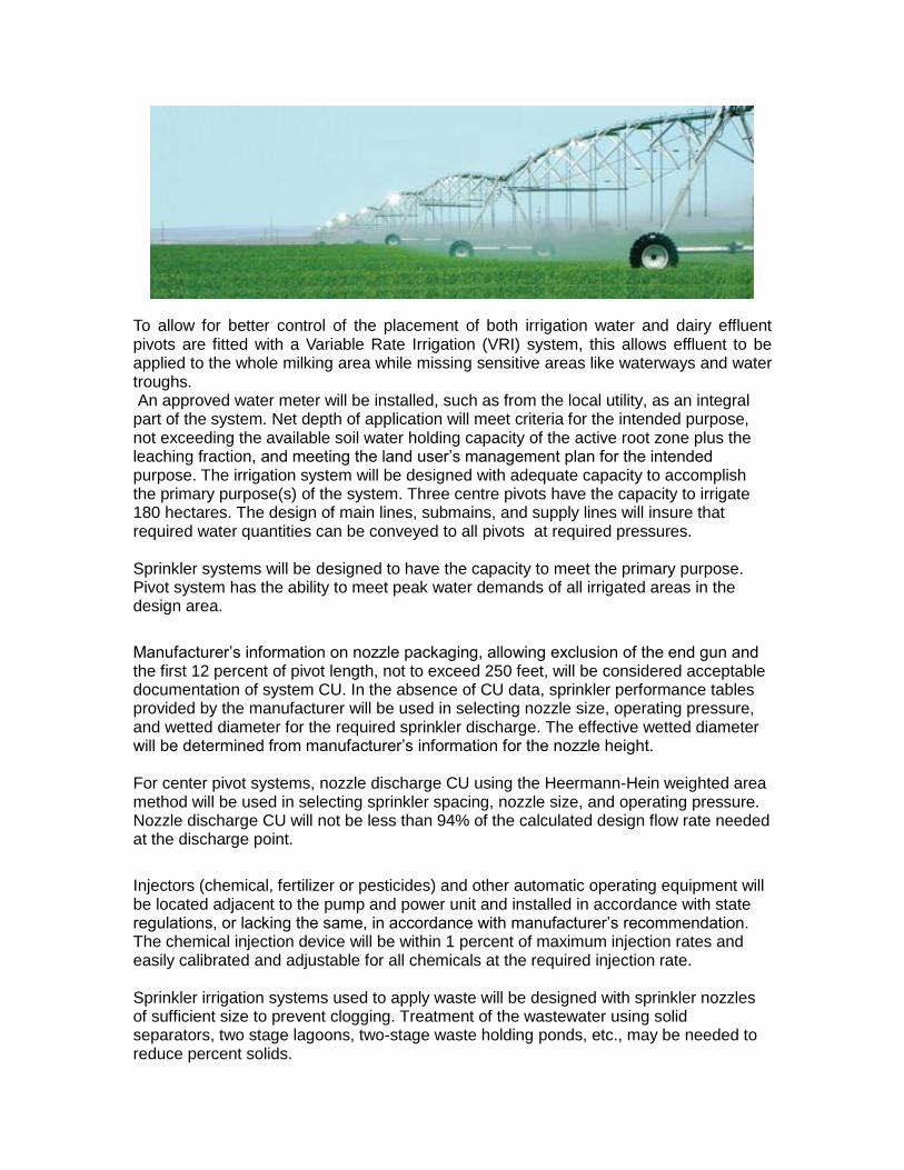
To allow for better control of the placement of both irrigation water and dairy effluent pivots are fitted with a Variable Rate Irrigation (VRI) system, this allows effluent to be applied to the whole milking area while missing sensitive areas like waterways and water troughs. An approved water meter will be installed, such as from the local utility, as an integral part of the system. Net depth of application will meet criteria for the intended purpose, not exceeding the available soil water holding capacity of the active root zone plus the leaching fraction, and meeting the land user’s management plan for the intended purpose. The irrigation system will be designed with adequate capacity to accomplish the primary purpose(s) of the system. Three centre pivots have the capacity to irrigate 180 hectares. The design of main lines, submains, and supply lines will insure that required water quantities can be conveyed to all pivots at required pressures. Sprinkler systems will be designed to have the capacity to meet the primary purpose. Pivot system has the ability to meet peak water demands of all irrigated areas in the design area.
Manufacturer’s information on nozzle packaging, allowing exclusion of the end gun and the first 12 percent of pivot length, not to exceed 250 feet, will be considered acceptable documentation of system CU. In the absence of CU data, sprinkler performance tables provided by the manufacturer will be used in selecting nozzle size, operating pressure, and wetted diameter for the required sprinkler discharge. The effective wetted diameter will be determined from manufacturer’s information for the nozzle height. For center pivot systems, nozzle discharge CU using the Heermann-Hein weighted area method will be used in selecting sprinkler spacing, nozzle size, and operating pressure. Nozzle discharge CU will not be less than 94% of the calculated design flow rate needed at the discharge point.
Injectors (chemical, fertilizer or pesticides) and other automatic operating equipment will be located adjacent to the pump and power unit and installed in accordance with state regulations, or lacking the same, in accordance with manufacturer’s recommendation. The chemical injection device will be within 1 percent of maximum injection rates and easily calibrated and adjustable for all chemicals at the required injection rate. Sprinkler irrigation systems used to apply waste will be designed with sprinkler nozzles of sufficient size to prevent clogging. Treatment of the wastewater using solid separators, two stage lagoons, two-stage waste holding ponds, etc., may be needed to reduce percent solids.
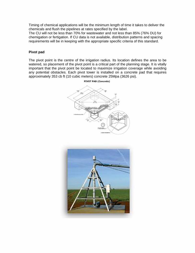
Timing of chemical applications will be the minimum length of time it takes to deliver the chemicals and flush the pipelines at rates specified by the label. The CU will not be less than 70% for wastewater and not less than 85% (76% DU) for chemigation or fertigation. If CU data is not available, distribution patterns and spacing requirements will be in keeping with the appropriate specific criteria of this standard.
Pivot pad The pivot point is the centre of the irrigation radius. Its location defines the area to be watered, so placement of the pivot point is a critical part of the planning stage. It is vitally important that the pivot point be located to maximize irrigation coverage while avoiding any potential obstacles. Each pivot tower is installed on a concrete pad that requires approximately 353 cb ft (10 cubic meters) concrete 25Mpa (3626 psi).
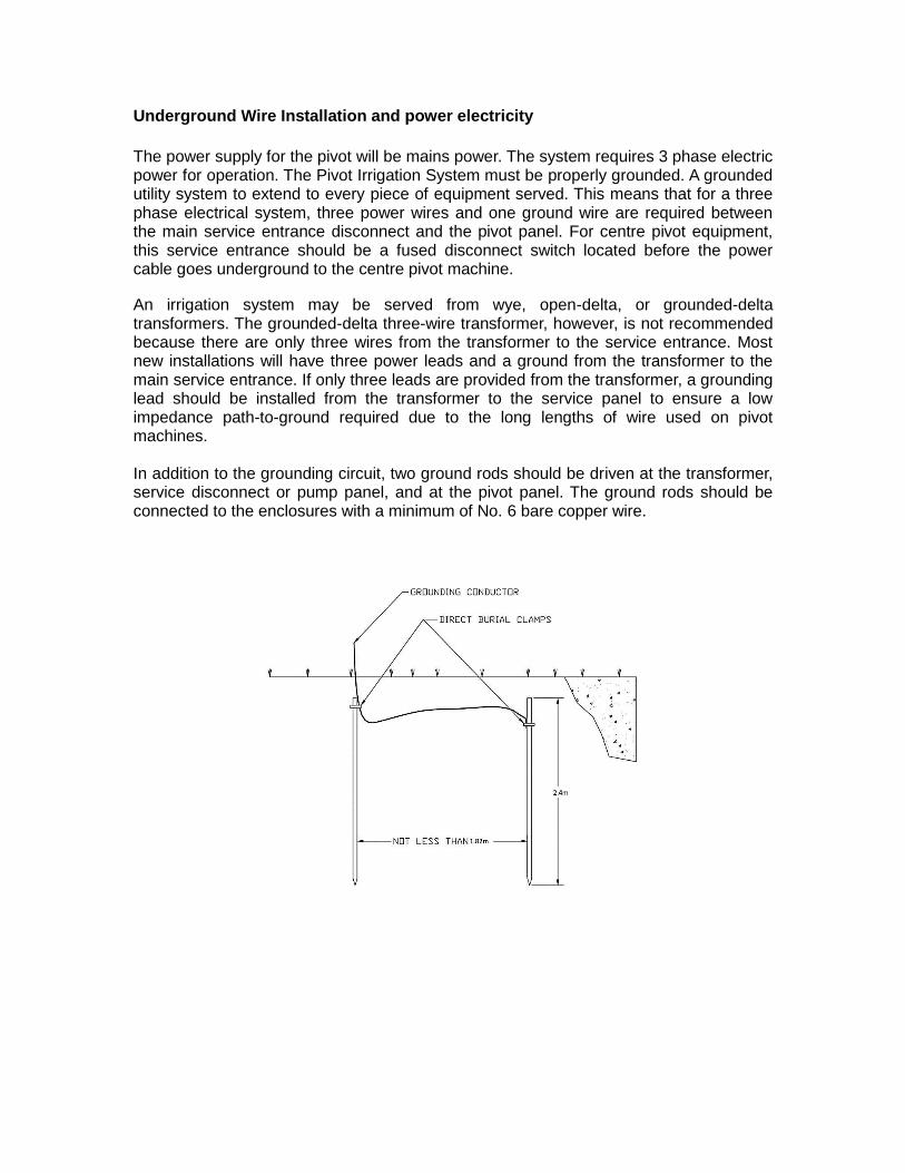
Underground Wire Installation and power electricity
The power supply for the pivot will be mains power. The system requires 3 phase electric power for operation. The Pivot Irrigation System must be properly grounded. A grounded utility system to extend to every piece of equipment served. This means that for a three phase electrical system, three power wires and one ground wire are required between the main service entrance disconnect and the pivot panel. For centre pivot equipment, this service entrance should be a fused disconnect switch located before the power cable goes underground to the centre pivot machine.
An irrigation system may be served from wye, open-delta, or grounded-delta transformers. The grounded-delta three-wire transformer, however, is not recommended because there are only three wires from the transformer to the service entrance. Most new installations will have three power leads and a ground from the transformer to the main service entrance. If only three leads are provided from the transformer, a grounding lead should be installed from the transformer to the service panel to ensure a low impedance path-to-ground required due to the long lengths of wire used on pivot machines. In addition to the grounding circuit, two ground rods should be driven at the transformer, service disconnect or pump panel, and at the pivot panel. The ground rods should be connected to the enclosures with a minimum of No. 6 bare copper wire.
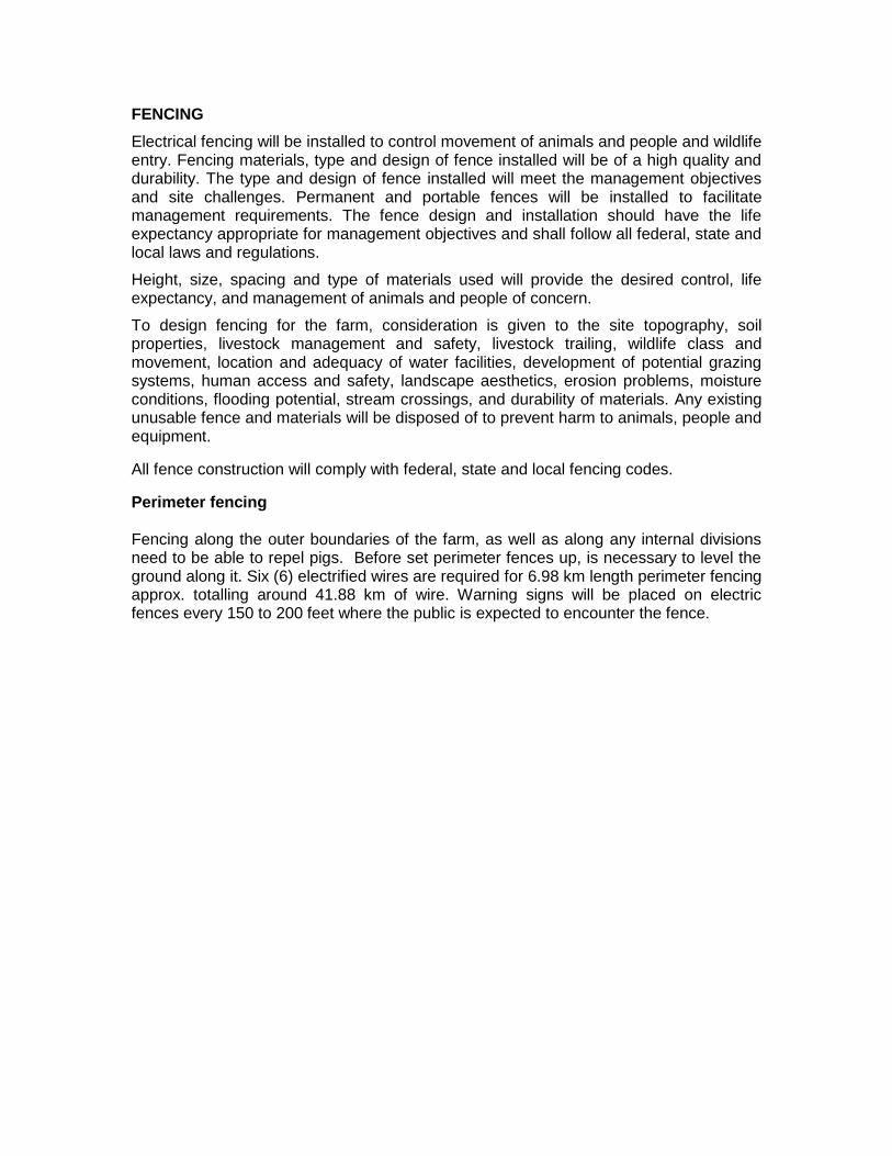
FENCING
Electrical fencing will be installed to control movement of animals and people and wildlife entry. Fencing materials, type and design of fence installed will be of a high quality and durability. The type and design of fence installed will meet the management objectives and site challenges. Permanent and portable fences will be installed to facilitate management requirements. The fence design and installation should have the life expectancy appropriate for management objectives and shall follow all federal, state and local laws and regulations.
Height, size, spacing and type of materials used will provide the desired control, life expectancy, and management of animals and people of concern.
To design fencing for the farm, consideration is given to the site topography, soil properties, livestock management and safety, livestock trailing, wildlife class and movement, location and adequacy of water facilities, development of potential grazing systems, human access and safety, landscape aesthetics, erosion problems, moisture conditions, flooding potential, stream crossings, and durability of materials. Any existing unusable fence and materials will be disposed of to prevent harm to animals, people and equipment.
All fence construction will comply with federal, state and local fencing codes.
Perimeter fencing Fencing along the outer boundaries of the farm, as well as along any internal divisions need to be able to repel pigs. Before set perimeter fences up, is necessary to level the ground along it. Six (6) electrified wires are required for 6.98 km length perimeter fencing approx. totalling around 41.88 km of wire. Warning signs will be placed on electric fences every 150 to 200 feet where the public is expected to encounter the fence.
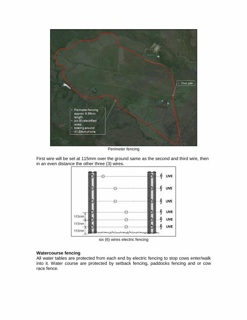
Perimeter fencing
First wire will be set at 115mm over the ground same as the second and third wire, then in an even distance the other three (3) wires.
six (6) wires electric fencing
Watercourse fencing All water tables are protected from each end by electric fencing to stop cows enter/walk into it. Water course are protected by setback fencing, paddocks fencing and or cow race fence.
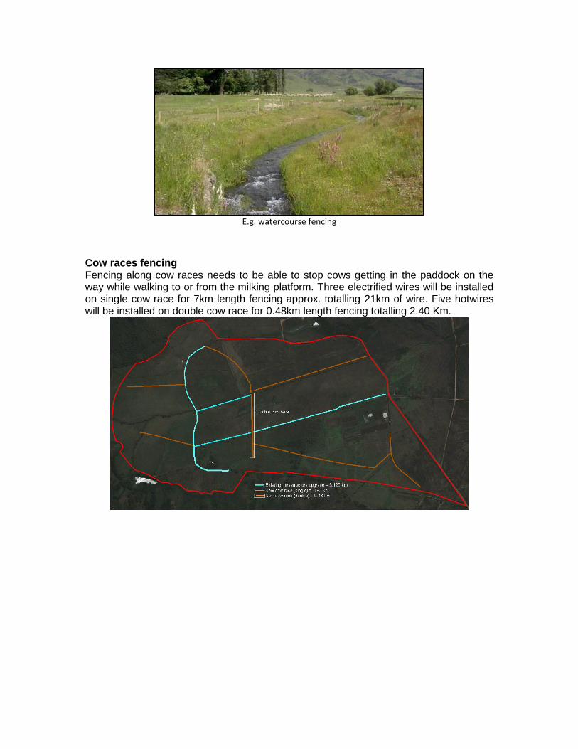
E.g. watercourse fencing
Cow races fencing Fencing along cow races needs to be able to stop cows getting in the paddock on the way while walking to or from the milking platform. Three electrified wires will be installed on single cow race for 7km length fencing approx. totalling 21km of wire. Five hotwires will be installed on double cow race for 0.48km length fencing totalling 2.40 Km.
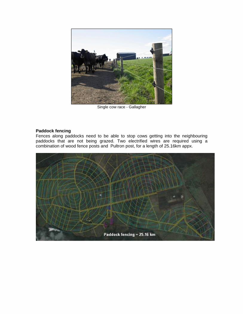
Single cow race - Gallagher
Paddock fencing Fences along paddocks need to be able to stop cows getting into the neighbouring paddocks that are not being grazed. Two electrified wires are required using a combination of wood fence posts and Pultron post, for a length of 25.16km appx.
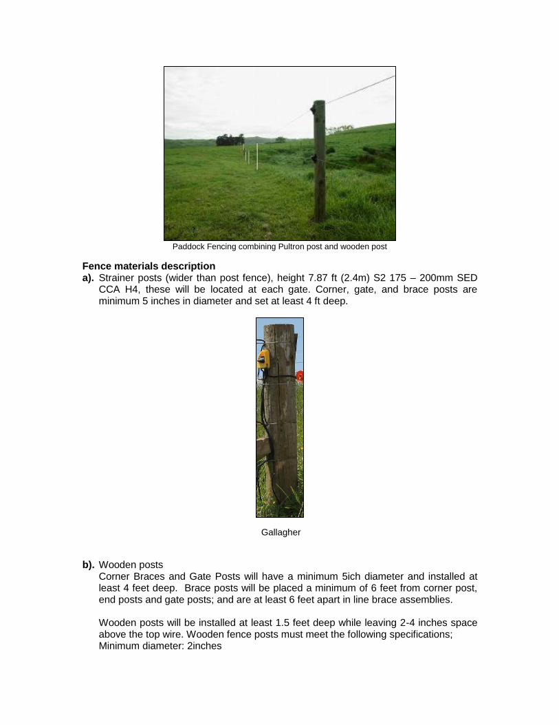
Paddock Fencing combining Pultron post and wooden post
Fence materials description a). Strainer posts (wider than post fence), height 7.87 ft (2.4m) S2 175 – 200mm SED
CCA H4, these will be located at each gate. Corner, gate, and brace posts are minimum 5 inches in diameter and set at least 4 ft deep.
Gallagher
b). Wooden posts
Corner Braces and Gate Posts will have a minimum 5ich diameter and installed at least 4 feet deep. Brace posts will be placed a minimum of 6 feet from corner post, end posts and gate posts; and are at least 6 feet apart in line brace assemblies. Wooden posts will be installed at least 1.5 feet deep while leaving 2-4 inches space above the top wire. Wooden fence posts must meet the following specifications; Minimum diameter: 2inches
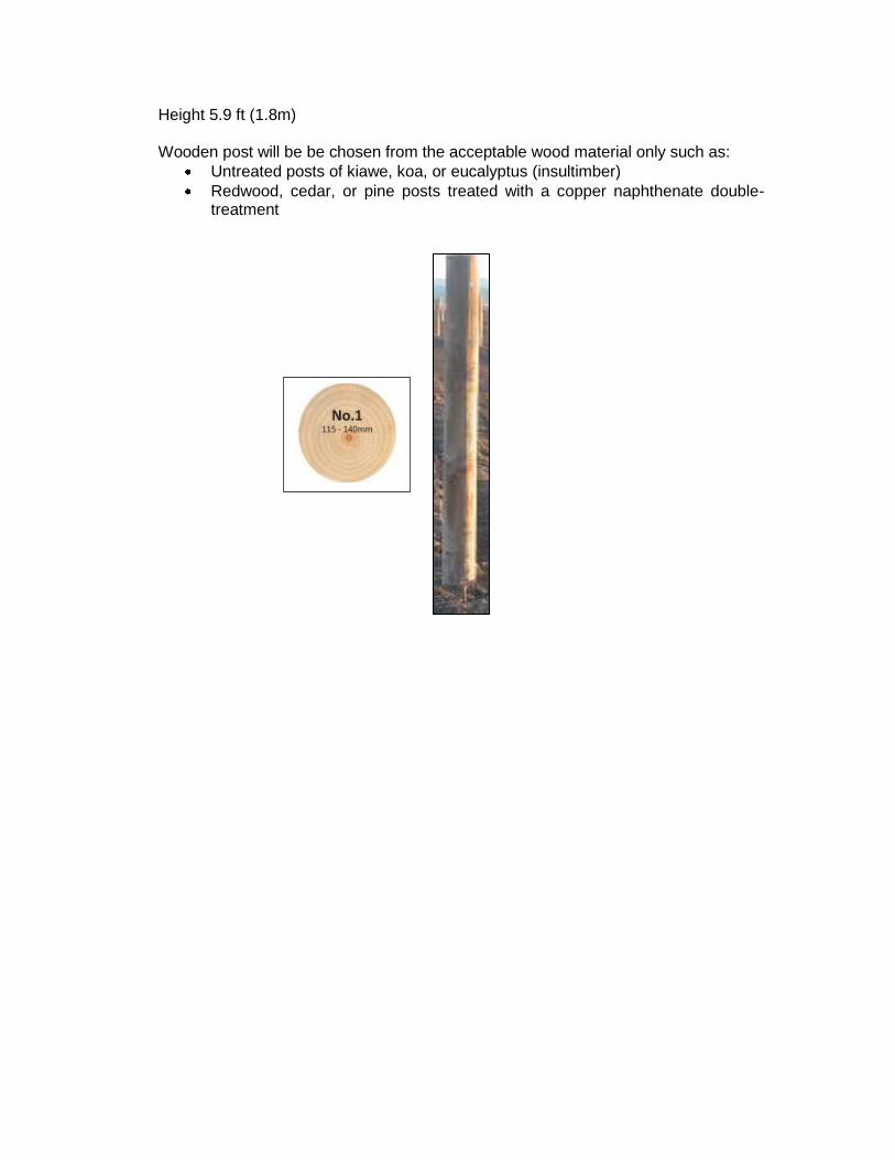
Height 5.9 ft (1.8m) Wooden post will be be chosen from the acceptable wood material only such as:
Untreated posts of kiawe, koa, or eucalyptus (insultimber)
Redwood, cedar, or pine posts treated with a copper naphthenate double-treatment
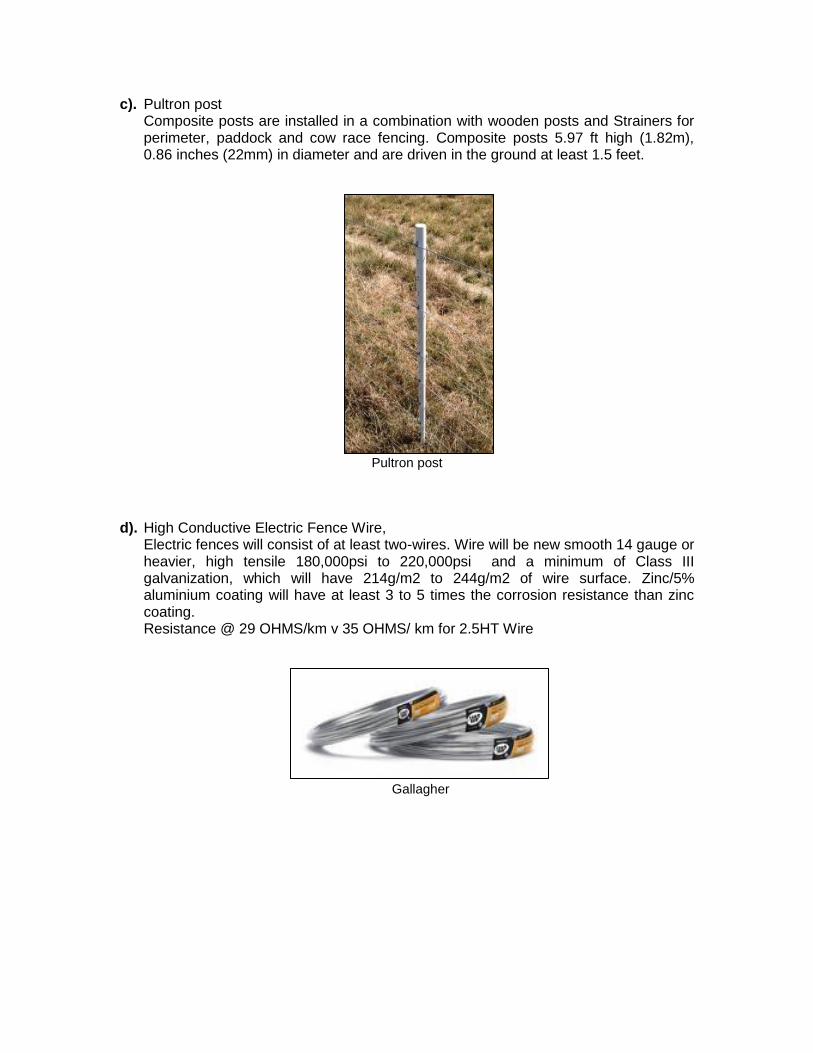
c). Pultron post Composite posts are installed in a combination with wooden posts and Strainers for perimeter, paddock and cow race fencing. Composite posts 5.97 ft high (1.82m), 0.86 inches (22mm) in diameter and are driven in the ground at least 1.5 feet.
Pultron post
d). High Conductive Electric Fence Wire,
Electric fences will consist of at least two-wires. Wire will be new smooth 14 gauge or heavier, high tensile 180,000psi to 220,000psi and a minimum of Class III galvanization, which will have 214g/m2 to 244g/m2 of wire surface. Zinc/5% aluminium coating will have at least 3 to 5 times the corrosion resistance than zinc coating. Resistance @ 29 OHMS/km v 35 OHMS/ km for 2.5HT Wire
Gallagher
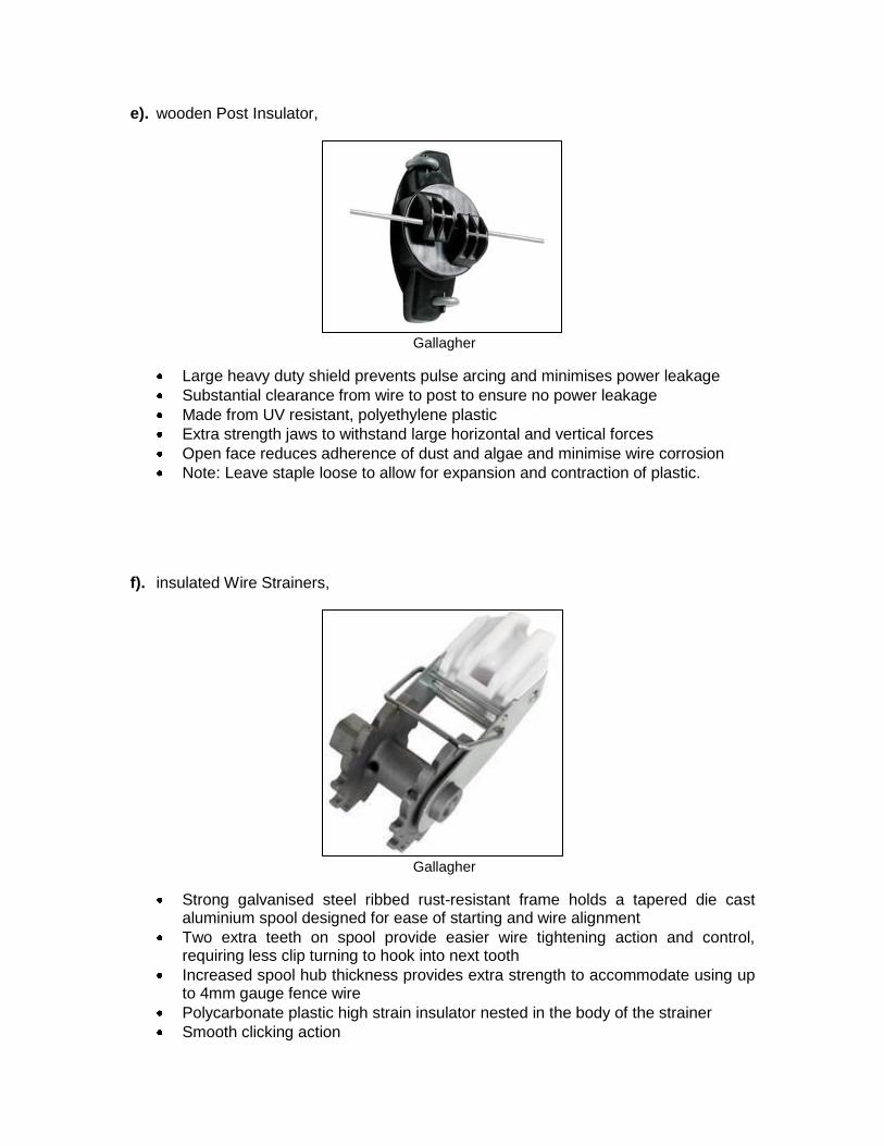
e). wooden Post Insulator,
Gallagher
Large heavy duty shield prevents pulse arcing and minimises power leakage
Substantial clearance from wire to post to ensure no power leakage
Made from UV resistant, polyethylene plastic
Extra strength jaws to withstand large horizontal and vertical forces
Open face reduces adherence of dust and algae and minimise wire corrosion
Note: Leave staple loose to allow for expansion and contraction of plastic.
f). insulated Wire Strainers,
Gallagher
Strong galvanised steel ribbed rust-resistant frame holds a tapered die cast aluminium spool designed for ease of starting and wire alignment
Two extra teeth on spool provide easier wire tightening action and control, requiring less clip turning to hook into next tooth
Increased spool hub thickness provides extra strength to accommodate using up to 4mm gauge fence wire
Polycarbonate plastic high strain insulator nested in the body of the strainer
Smooth clicking action
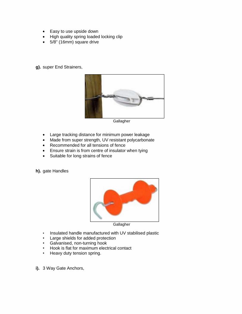
Easy to use upside down
High quality spring loaded locking clip
5/8" (16mm) square drive g). super End Strainers,
Gallagher
Large tracking distance for minimum power leakage
Made from super strength, UV resistant polycarbonate
Recommended for all tensions of fence
Ensure strain is from centre of insulator when tying
Suitable for long strains of fence
h). gate Handles
Gallagher
• Insulated handle manufactured with UV stabilised plastic • Large shields for added protection • Galvanised, non-turning hook • Hook is flat for maximum electrical contact • Heavy duty tension spring.
i). 3 Way Gate Anchors,
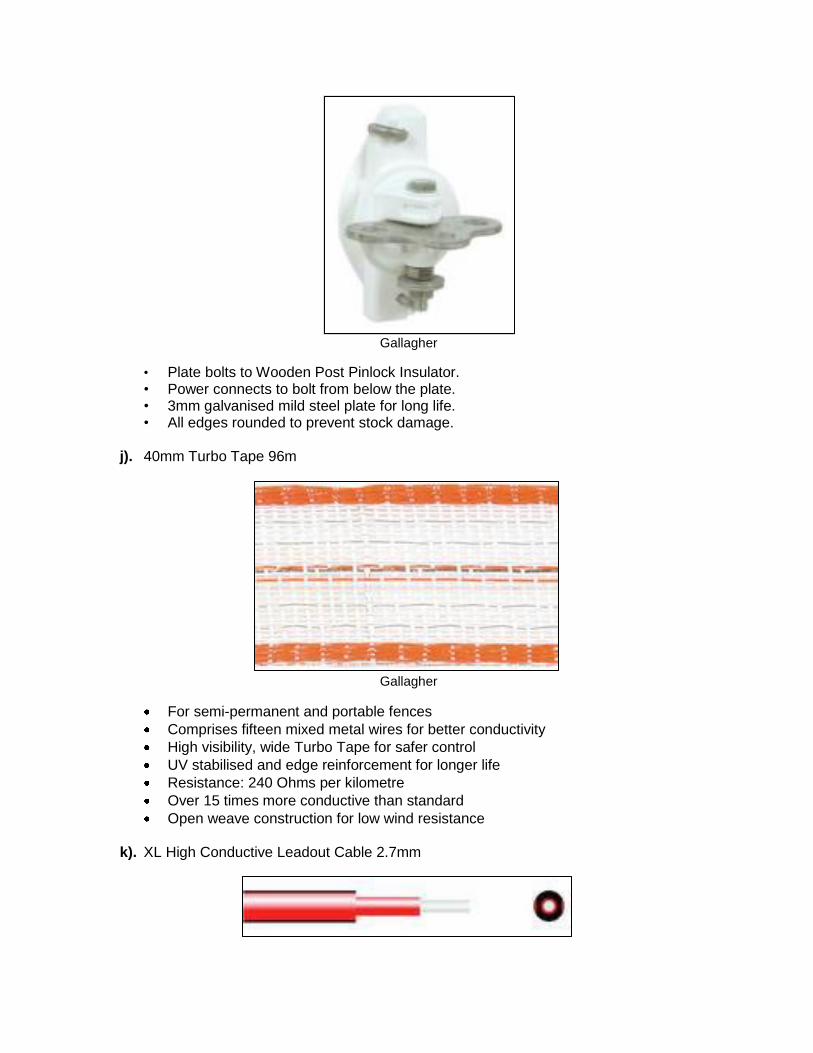
Gallagher
• Plate bolts to Wooden Post Pinlock Insulator. • Power connects to bolt from below the plate. • 3mm galvanised mild steel plate for long life. • All edges rounded to prevent stock damage.
j). 40mm Turbo Tape 96m
Gallagher
For semi-permanent and portable fences
Comprises fifteen mixed metal wires for better conductivity
High visibility, wide Turbo Tape for safer control
UV stabilised and edge reinforcement for longer life
Resistance: 240 Ohms per kilometre
Over 15 times more conductive than standard
Open weave construction for low wind resistance k). XL High Conductive Leadout Cable 2.7mm
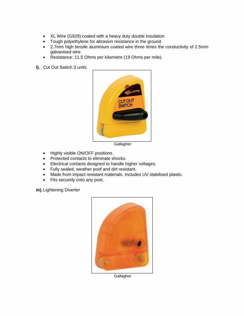
XL Wire (G929) coated with a heavy duty double insulation
Tough polyethylene for abrasion resistance in the ground
2.7mm high tensile aluminium coated wire three times the conductivity of 2.5mm galvanised wire
Resistance: 11.5 Ohms per kilometre (19 Ohms per mile).
l). Cut Out Switch 3 units
Gallagher
Highly visible ON/OFF positions.
Protected contacts to eliminate shocks.
Electrical contacts designed to handle higher voltages.
Fully sealed, weather poof and dirt resistant.
Made from impact resistant materials. Includes UV stabilised plastic.
Fits securely onto any post.
m). Lightening Diverter
Gallagher
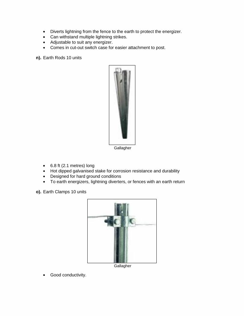
Diverts lightning from the fence to the earth to protect the energizer.
Can withstand multiple lightning strikes.
Adjustable to suit any energizer.
Comes in cut-out switch case for easier attachment to post. n). Earth Rods 10 units
Gallagher
6.8 ft (2.1 metres) long
Hot dipped galvanised stake for corrosion resistance and durability
Designed for hard ground conditions
To earth energizers, lightning diverters, or fences with an earth return
o). Earth Clamps 10 units
Gallagher
Good conductivity.
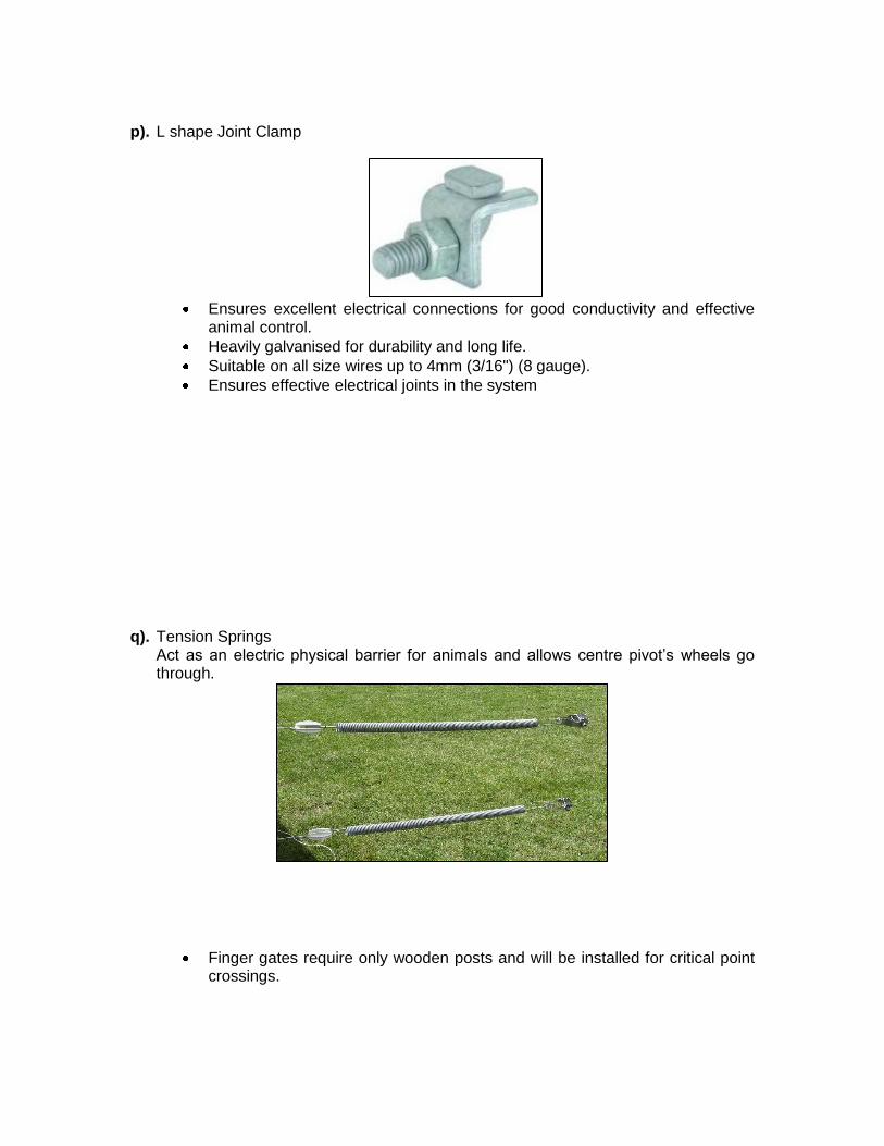
p). L shape Joint Clamp
Ensures excellent electrical connections for good conductivity and effective
animal control.
Heavily galvanised for durability and long life.
Suitable on all size wires up to 4mm (3/16") (8 gauge).
Ensures effective electrical joints in the system
q). Tension Springs Act as an electric physical barrier for animals and allows centre pivot’s wheels go through.
Finger gates require only wooden posts and will be installed for critical point crossings.
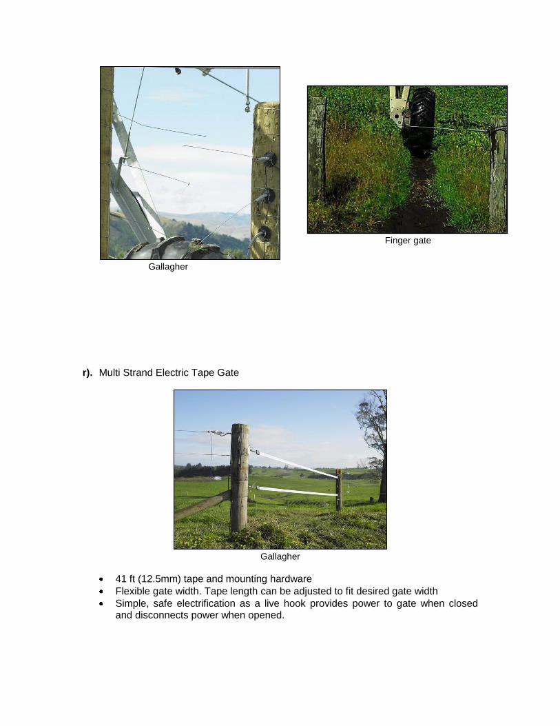
Gallagher
r). Multi Strand Electric Tape Gate
Gallagher
41 ft (12.5mm) tape and mounting hardware
Flexible gate width. Tape length can be adjusted to fit desired gate width
Simple, safe electrification as a live hook provides power to gate when closed and disconnects power when opened.
Finger gate
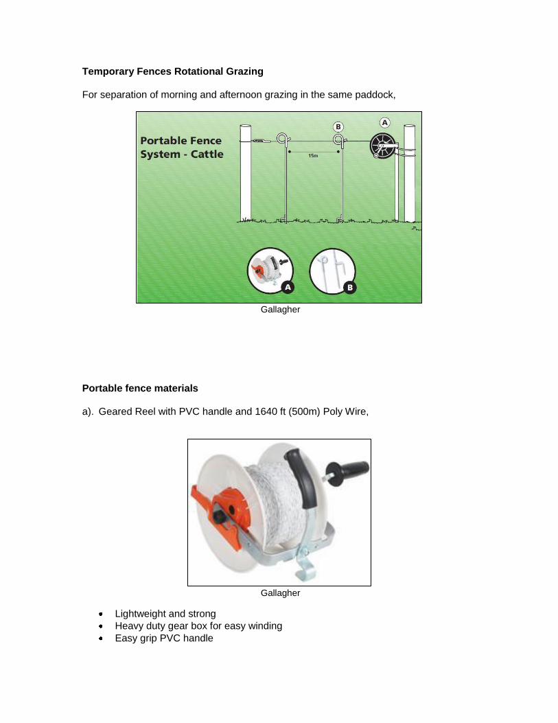
Temporary Fences Rotational Grazing For separation of morning and afternoon grazing in the same paddock,
Gallagher
Portable fence materials
a). Geared Reel with PVC handle and 1640 ft (500m) Poly Wire,
Gallagher
Lightweight and strong
Heavy duty gear box for easy winding
Easy grip PVC handle
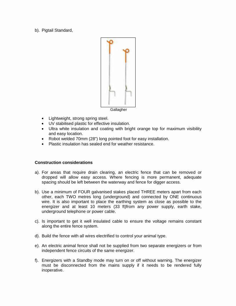
b). Pigtail Standard,
Gallagher
Lightweight, strong spring steel.
UV stabilised plastic for effective insulation.
Ultra white insulation and coating with bright orange top for maximum visibility and easy location.
Robot welded 70mm (28") long pointed foot for easy installation.
Plastic insulation has sealed end for weather resistance.
Construction considerations
a). For areas that require drain clearing, an electric fence that can be removed or dropped will allow easy access. Where fencing is more permanent, adequate spacing should be left between the waterway and fence for digger access.
b). Use a minimum of FOUR galvanised stakes placed THREE meters apart from each other, each TWO metres long (underground) and connected by ONE continuous wire. It is also important to place the earthing system as close as possible to the energizer and at least 10 meters (33 ft)from any power supply, earth stake, underground telephone or power cable.
c). Is important to get it well insulated cable to ensure the voltage remains constant
along the entire fence system.
d). Build the fence with all wires electrified to control your animal type.
e). An electric animal fence shall not be supplied from two separate energizers or from independent fence circuits of the same energizer.
f). Energizers with a Standby mode may turn on or off without warning. The energizer
must be disconnected from the mains supply if it needs to be rendered fully inoperative.
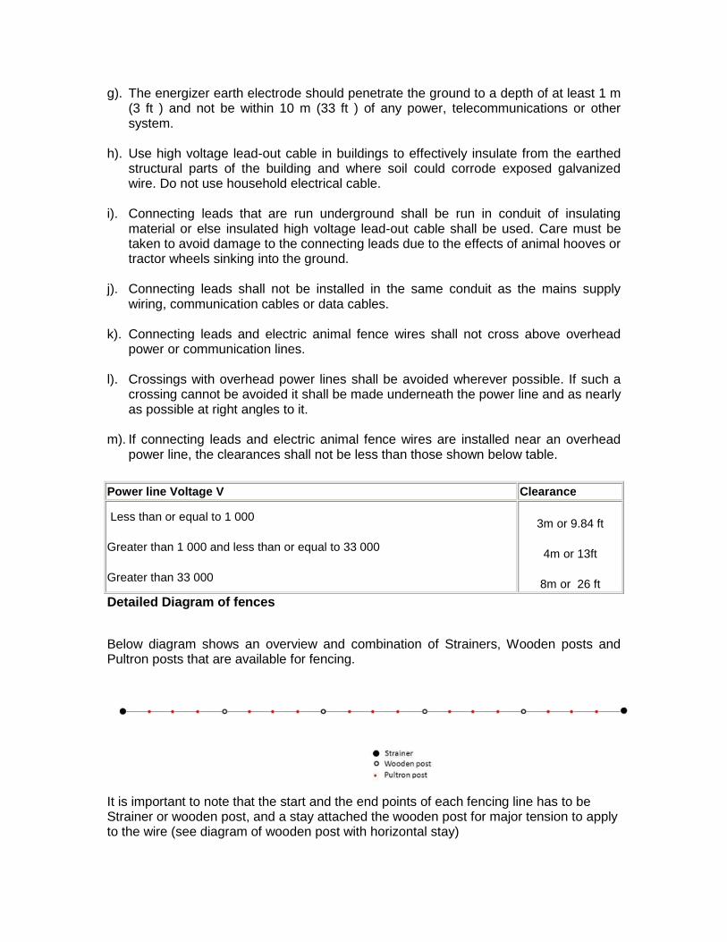
g). The energizer earth electrode should penetrate the ground to a depth of at least 1 m (3 ft ) and not be within 10 m (33 ft ) of any power, telecommunications or other system.
h). Use high voltage lead-out cable in buildings to effectively insulate from the earthed
structural parts of the building and where soil could corrode exposed galvanized wire. Do not use household electrical cable.
i). Connecting leads that are run underground shall be run in conduit of insulating
material or else insulated high voltage lead-out cable shall be used. Care must be taken to avoid damage to the connecting leads due to the effects of animal hooves or tractor wheels sinking into the ground.
j). Connecting leads shall not be installed in the same conduit as the mains supply
wiring, communication cables or data cables.
k). Connecting leads and electric animal fence wires shall not cross above overhead power or communication lines.
l). Crossings with overhead power lines shall be avoided wherever possible. If such a
crossing cannot be avoided it shall be made underneath the power line and as nearly as possible at right angles to it.
m). If connecting leads and electric animal fence wires are installed near an overhead
power line, the clearances shall not be less than those shown below table.
Detailed Diagram of fences
Below diagram shows an overview and combination of Strainers, Wooden posts and Pultron posts that are available for fencing.
It is important to note that the start and the end points of each fencing line has to be Strainer or wooden post, and a stay attached the wooden post for major tension to apply to the wire (see diagram of wooden post with horizontal stay)
Power line Voltage V Clearance
Less than or equal to 1 000
Greater than 1 000 and less than or equal to 33 000
Greater than 33 000
3m or 9.84 ft
4m or 13ft
8m or 26 ft
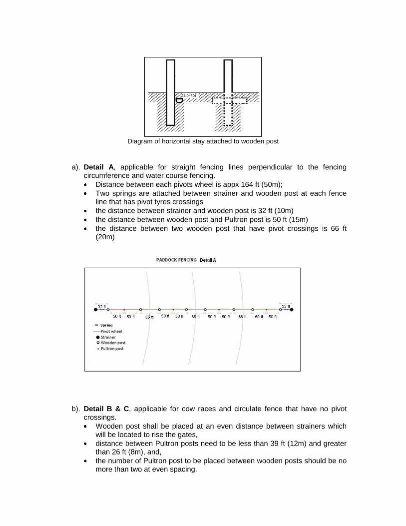
Diagram of horizontal stay attached to wooden post
a). Detail A, applicable for straight fencing lines perpendicular to the fencing circumference and water course fencing.
Distance between each pivots wheel is appx 164 ft (50m);
Two springs are attached between strainer and wooden post at each fence line that has pivot tyres crossings
the distance between strainer and wooden post is 32 ft (10m)
the distance between wooden post and Pultron post is 50 ft (15m)
the distance between two wooden post that have pivot crossings is 66 ft (20m)
b). Detail B & C, applicable for cow races and circulate fence that have no pivot crossings.
Wooden post shall be placed at an even distance between strainers which will be located to rise the gates,
distance between Pultron posts need to be less than 39 ft (12m) and greater than 26 ft (8m), and,
the number of Pultron post to be placed between wooden posts should be no more than two at even spacing.
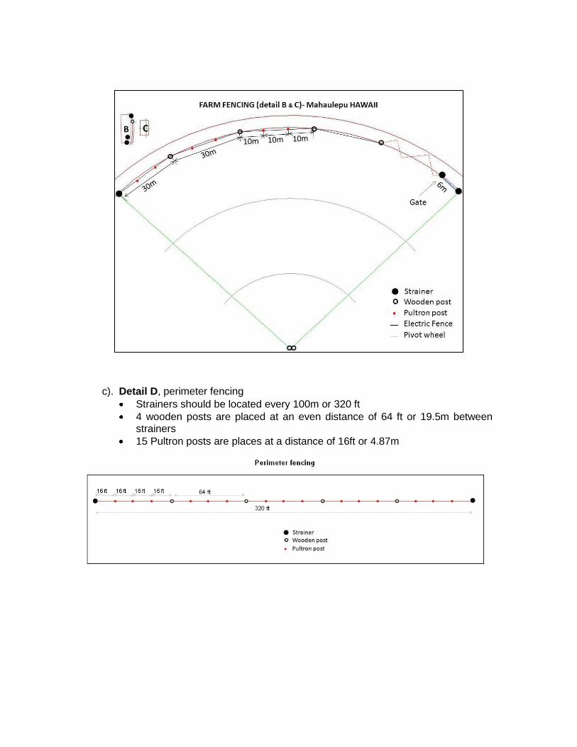
c). Detail D, perimeter fencing
Strainers should be located every 100m or 320 ft
4 wooden posts are placed at an even distance of 64 ft or 19.5m between strainers
15 Pultron posts are places at a distance of 16ft or 4.87m
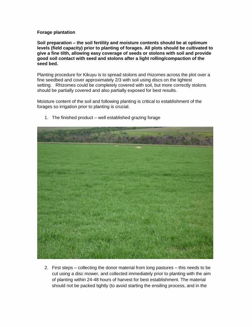
Forage plantation Soil preparation – the soil fertility and moisture contents should be at optimum levels (field capacity) prior to planting of forages. All plots should be cultivated to give a fine tilth, allowing easy coverage of seeds or stolons with soil and provide good soil contact with seed and stolons after a light rolling/compaction of the seed bed.
Planting procedure for Kikuyu is to spread stolons and rhizomes across the plot over a fine seedbed and cover approximately 2/3 with soil using discs on the lightest setting. Rhizomes could be completely covered with soil, but more correctly stolons should be partially covered and also partially exposed for best results.
Moisture content of the soil and following planting is critical to establishment of the forages so irrigation prior to planting is crucial.
1. The finished product – well established grazing forage
2. First steps – collecting the donor material from long pastures – this needs to be
cut using a disc mower, and collected immediately prior to planting with the aim
of planting within 24-48 hours of harvest for best establishment. The material
should not be packed tightly (to avoid starting the ensiling process, and in the
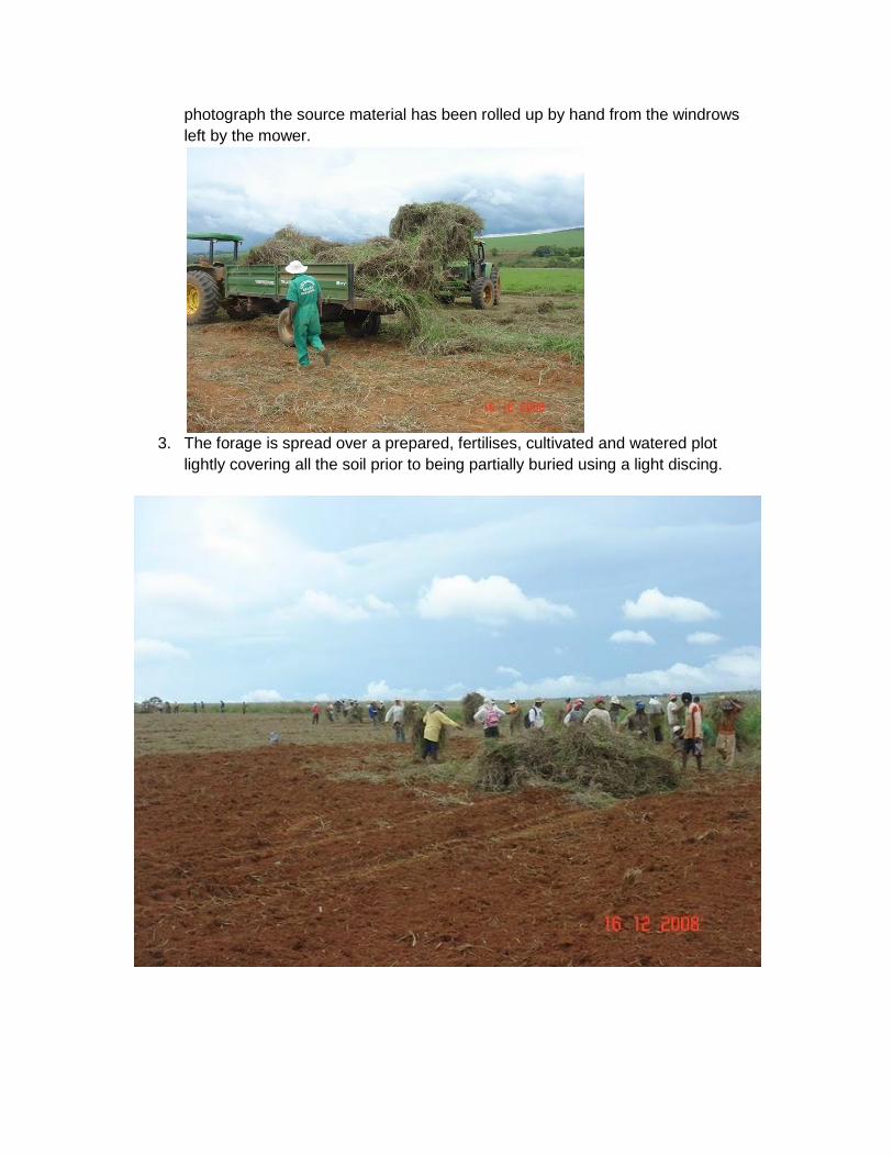
photograph the source material has been rolled up by hand from the windrows
left by the mower.
3. The forage is spread over a prepared, fertilises, cultivated and watered plot
lightly covering all the soil prior to being partially buried using a light discing.
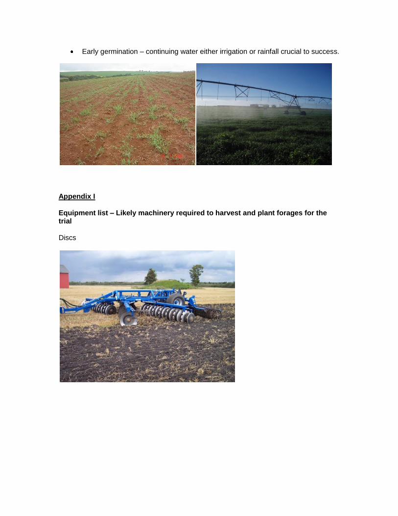
Early germination – continuing water either irrigation or rainfall crucial to success.
Appendix I Equipment list – Likely machinery required to harvest and plant forages for the trial Discs
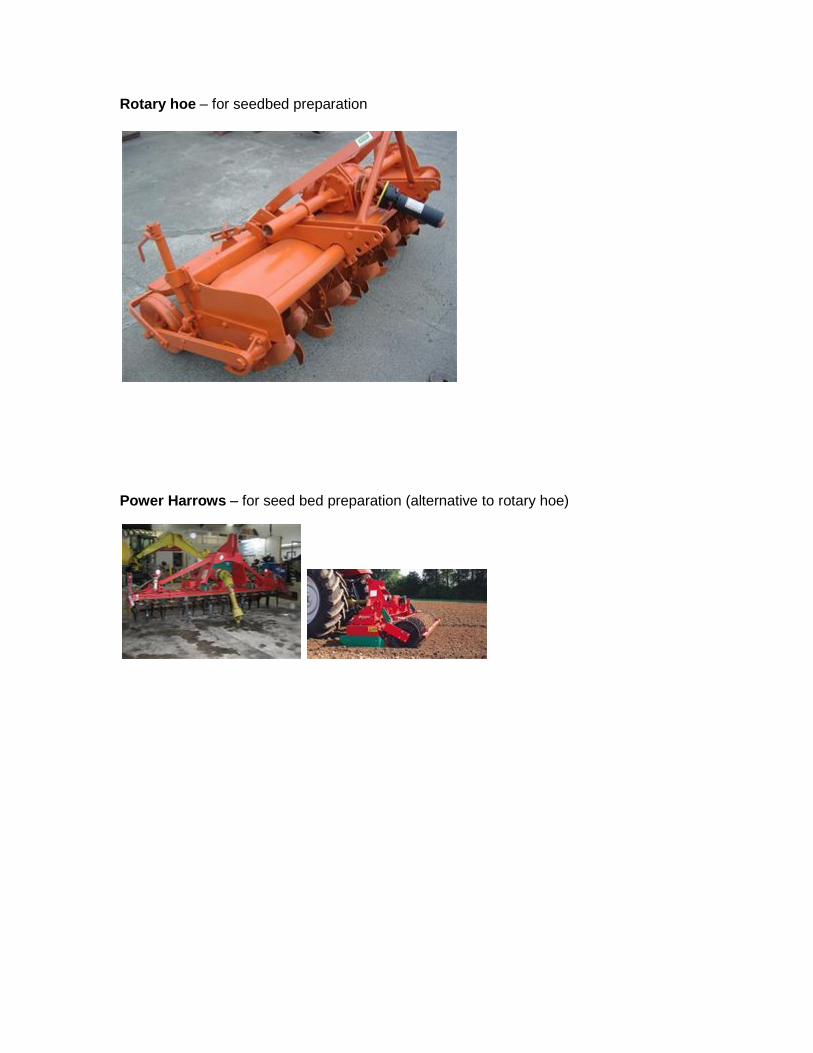
Rotary hoe – for seedbed preparation
Power Harrows – for seed bed preparation (alternative to rotary hoe)
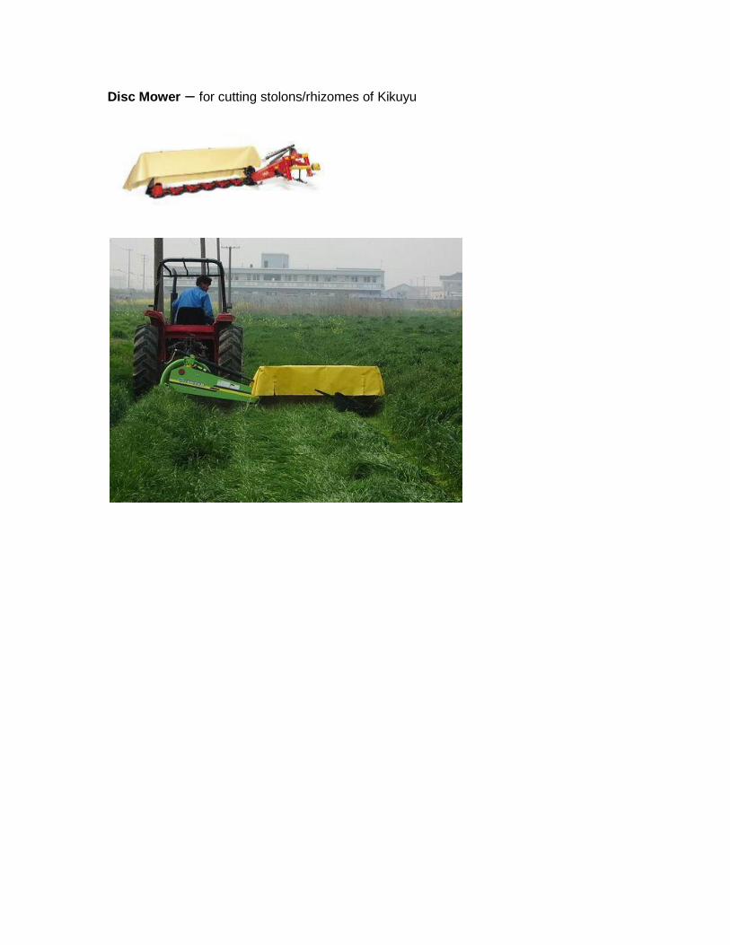
Disc Mower – for cutting stolons/rhizomes of Kikuyu
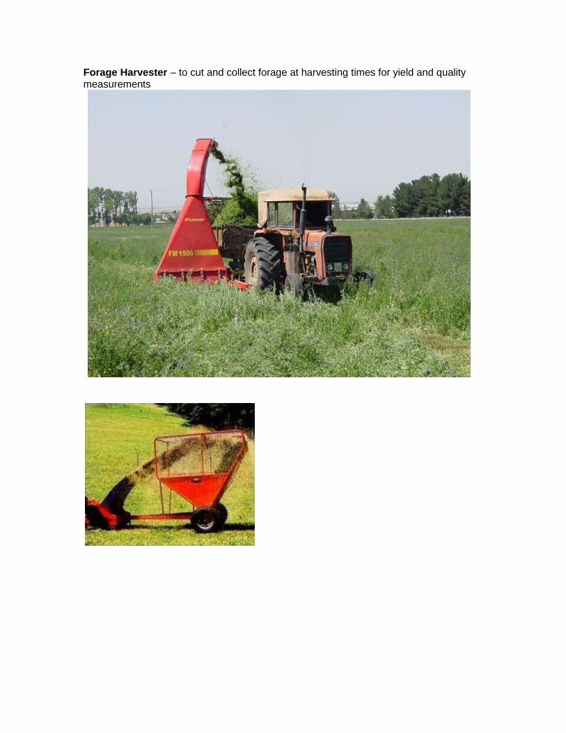
Forage Harvester – to cut and collect forage at harvesting times for yield and quality measurements
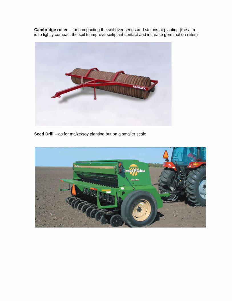
Cambridge roller – for compacting the soil over seeds and stolons at planting (the aim is to lightly compact the soil to improve soil/plant contact and increase germination rates)
Seed Drill – as for maize/soy planting but on a smaller scale
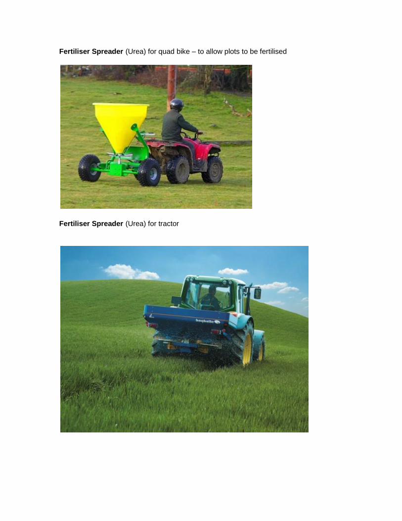
Fertiliser Spreader (Urea) for quad bike – to allow plots to be fertilised
Fertiliser Spreader (Urea) for tractor
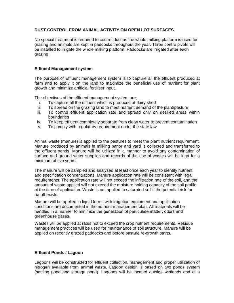
DUST CONTROL FROM ANIMAL ACTIVITY ON OPEN LOT SURFACES No special treatment is required to control dust as the whole milking platform is used for grazing and animals are kept in paddocks throughout the year. Three centre pivots will be installed to irrigate the whole milking platform. Paddocks are irrigated after each grazing. Effluent Management system The purpose of Effluent management system is to capture all the effluent produced at farm and to apply it on the land to maximize the beneficial use of nutrient for plant growth and minimize artificial fertiliser input. The objectives of the effluent management system are;
i. To capture all the effluent which is produced at dairy shed ii. To spread on the grazing land to meet nutrient demand of the plant/pasture iii. To control effluent application rate and spread only on desired areas within
boundaries iv. To keep effluent completely separate from clean water to prevent contamination v. To comply with regulatory requirement under the state law
Animal waste (manure) is applied to the pastures to meet the plant nutrient requirement. Manure produced by animals in milking parlor and yard is collected and transferred to the effluent ponds. Manure will be utilized in a manner to avoid any contamination of surface and ground water supplies and records of the use of wastes will be kept for a minimum of five years. The manure will be sampled and analysed at least once each year to identify nutrient and specification concentrations. Manure application rate will be consistent with legal requirements. The application rate will not exceed the infiltration rate of the soil, and the amount of waste applied will not exceed the moisture holding capacity of the soil profile at the time of application. Waste is not applied to saturated soil if the potential risk for runoff exists.
Manure will be applied in liquid forms with irrigation equipment and application conditions are documented in the nutrient management plan. All materials will be handled in a manner to minimize the generation of particulate matter, odors and greenhouse gases.
Wastes will be applied at rates not to exceed the crop nutrient requirements. Residue management practices will be used for maintenance of soil structure. Manure will be applied on recently grazed paddocks and before pasture re-growth starts.
Effluent Ponds / Lagoon Lagoons will be constructed for effluent collection, management and proper utilization of nitrogen available from animal waste. Lagoon design is based on two ponds system (settling pond and storage pond). Lagoons will be located outside wetlands and at a
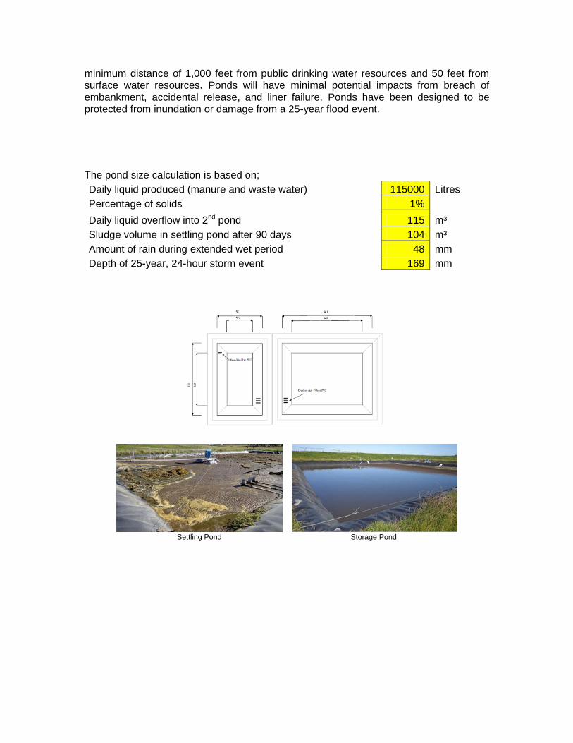
minimum distance of 1,000 feet from public drinking water resources and 50 feet from surface water resources. Ponds will have minimal potential impacts from breach of embankment, accidental release, and liner failure. Ponds have been designed to be protected from inundation or damage from a 25-year flood event.
The pond size calculation is based on;
Daily liquid produced (manure and waste water) 115000 Litres
Percentage of solids 1% Daily liquid overflow into 2nd pond 115 m³
Sludge volume in settling pond after 90 days 104 m³
Amount of rain during extended wet period 48 mm
Depth of 25-year, 24-hour storm event 169 mm
Settling Pond Storage Pond
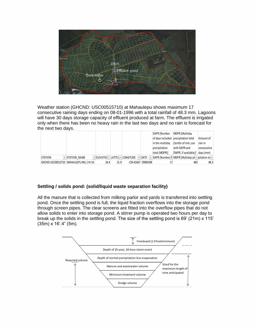
Weather station (GHCND: USC00515710) at Mahaulepu shows maximum 17 consecutive raining days ending on 08-01-1996 with a total rainfall of 48.3 mm. Lagoons will have 30 days storage capacity of effluent produced at farm. The effluent is irrigated only when there has been no heavy rain in the last two days and no rain is forecast for the next two days.
Settling / solids pond: (solid/liquid waste separation facility)
All the manure that is collected from milking parlor and yards is transferred into settling pond. Once the settling pond is full, the liquid fraction overflows into the storage pond through screen pipes. The clear screens are fitted into the overflow pipes that do not allow solids to enter into storage pond. A stirrer pump is operated two hours per day to break up the solids in the settling pond. The size of the settling pond is 69’ (21m) x 115’ (35m) x 16’.4” (5m).
DAPR [Number
of days included
in the multiday
precipitation
total (MDPR)]
MDPR [Multiday
precipitation total
(tenths of mm; use
with DAPR and
DWPR, if available)]
Amount of
rain in
consecutive
days (mm)
STATION STATION_NAME ELEVATION LATITUDE LONGITUDE DATE DAPR [Number of days included in the multiday precipitation total (MDPR)]MDPR [Multiday precipitation total (tenths of mm; use with DAPR and DWPR, if available)]
GHCND:USC00515710 MAHAULEPU 941.1 HI US 24.4 21.9 -159.41667 19960108 17 483 48.3
Required volume
Sized for the
maximum length of
time anticipated
Depth of normal precipitation less evaporation
Freeboard (1.0 footminimum)
Depth of 25-year, 24-hour storm event
Sludge volume
Manure and wastewater volume
Minimum treatment volume
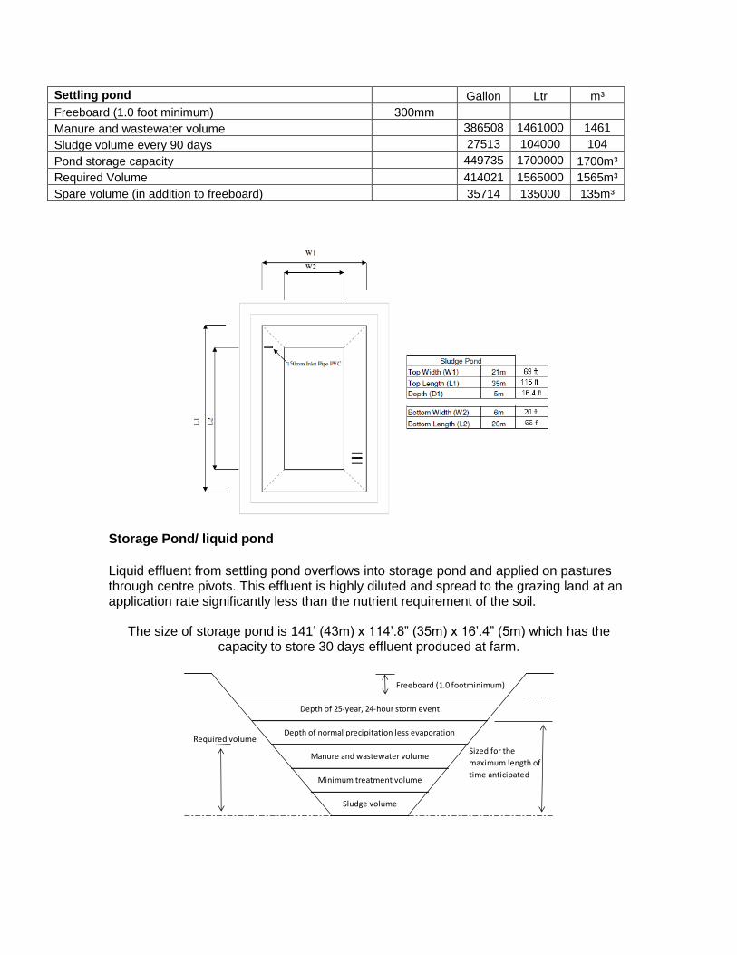
Settling pond Gallon Ltr m³
Freeboard (1.0 foot minimum) 300mm
Manure and wastewater volume 386508 1461000 1461
Sludge volume every 90 days 27513 104000 104
Pond storage capacity
449735 1700000 1700m³
Required Volume
414021 1565000 1565m³
Spare volume (in addition to freeboard) 35714 135000 135m³
Storage Pond/ liquid pond
Liquid effluent from settling pond overflows into storage pond and applied on pastures through centre pivots. This effluent is highly diluted and spread to the grazing land at an application rate significantly less than the nutrient requirement of the soil.
The size of storage pond is 141’ (43m) x 114’.8” (35m) x 16’.4” (5m) which has the capacity to store 30 days effluent produced at farm.
Required volume
Sized for the
maximum length of
time anticipated
Depth of normal precipitation less evaporation
Freeboard (1.0 footminimum)
Depth of 25-year, 24-hour storm event
Sludge volume
Manure and wastewater volume
Minimum treatment volume
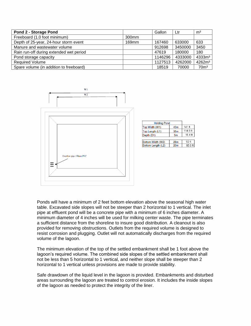
Pond 2 - Storage Pond Gallon Ltr m³
Freeboard (1.0 foot minimum) 300mm
Depth of 25-year, 24-hour storm event 169mm 167460 633000 633
Manure and wastewater volume 912698 3450000 3450
Rain run-off during extended wet period 47619 180000 180
Pond storage capacity
1146296 4333000 4333m³
Required Volume
1127513 4262000 4262m³
Spare volume (in addition to freeboard) 18519 70000 70m³
Ponds will have a minimum of 2 feet bottom elevation above the seasonal high water table. Excavated side slopes will not be steeper than 2 horizontal to 1 vertical. The inlet pipe at effluent pond will be a concrete pipe with a minimum of 6 inches diameter. A minimum diameter of 4 inches will be used for milking center waste. The pipe terminates a sufficient distance from the shoreline to insure good distribution. A cleanout is also provided for removing obstructions. Outlets from the required volume is designed to resist corrosion and plugging. Outlet will not automatically discharges from the required volume of the lagoon. The minimum elevation of the top of the settled embankment shall be 1 foot above the lagoon’s required volume. The combined side slopes of the settled embankment shall not be less than 5 horizontal to 1 vertical, and neither slope shall be steeper than 2 horizontal to 1 vertical unless provisions are made to provide stability. Safe drawdown of the liquid level in the lagoon is provided. Embankments and disturbed areas surrounding the lagoon are treated to control erosion. It includes the inside slopes of the lagoon as needed to protect the integrity of the liner.

The lagoon will be fenced around the perimeter and warning signs posted to prevent children and others from using it for other than its intended purpose. A marker or water level measuring device will be installed in the Lagoon to measure the stored volume and/or storage capacity remaining. The maximum operating level is the lagoon level that provides the required lagoon volume less the 25-year, 24-hour storm event precipitation and do not exceed the site and aeration equipment limitations. The entire pond area will be cleared of all trees, stumps, roots, brush, boulders, sod and debris. Topsoil containing more than 10% organic matter will be removed. All material cleared from the area will be disposed of at sites away from the work area, in accordance to state and county laws.
To establish vegetation, the topsoil and sod will be stockpiled and spread on the completed pond. Foundation surfaces will be sloped no steeper than 1:1. The foundation area will be stripped of all loose material, and thoroughly scarified before placement of the first layer of fill material. The foundation surface will have moisture added and be compacted prior to fill placement. Required excavations will be cut to the lines and grades shown on the drawings. Excavated materials could be used to construct the embankment. The material placed in the fill should be free of sod, roots, and stones over 3 inches (77mm) in diameter. All fill material are obtained from required excavations and designated borrow areas. Fill will be placed once required excavation and foundation preparation have been completed and the foundation has been inspected and approved. The foundation surface should be scarified and loosened to a depth of not less than 2 inches (51mm) before placement of the first layer of fill. If the surface of any layer becomes too hard and smooth for proper bond with the succeeding layer, it shall be scarified parallel to the axis of the fill to a depth of not less than 2 inches (51mm) before the next layer is placed. The placing and spreading of fill material is started at the lowest point of the foundation. The fill should be brought up in horizontal layers of a maximum thickness as shown in the Compaction section below. The fill will be constructed in continuous horizontal layers except where openings or sectionalized fills are required. The bonding surface will be treated the same as that specified for the foundation so as to insure a good bond with the new fill. Embankments shall be constructed in continuous horizontal layers. The distribution and gradation of materials shall be such that no lenses, pockets, streaks, or layers of material differ substantially in texture or gradation from the surrounding material. The complete work will conform to the lines, grades and elevations shown on the drawings or as staked in the field. Selected backfill material is placed around structures and pipe conduits at about the same rate on all sides of prevent damage from unequal loading. Fill placed around structures will be brought up at approximately uniform height, not to exceed a difference in elevation of 8 inches, on all sides of the structure.
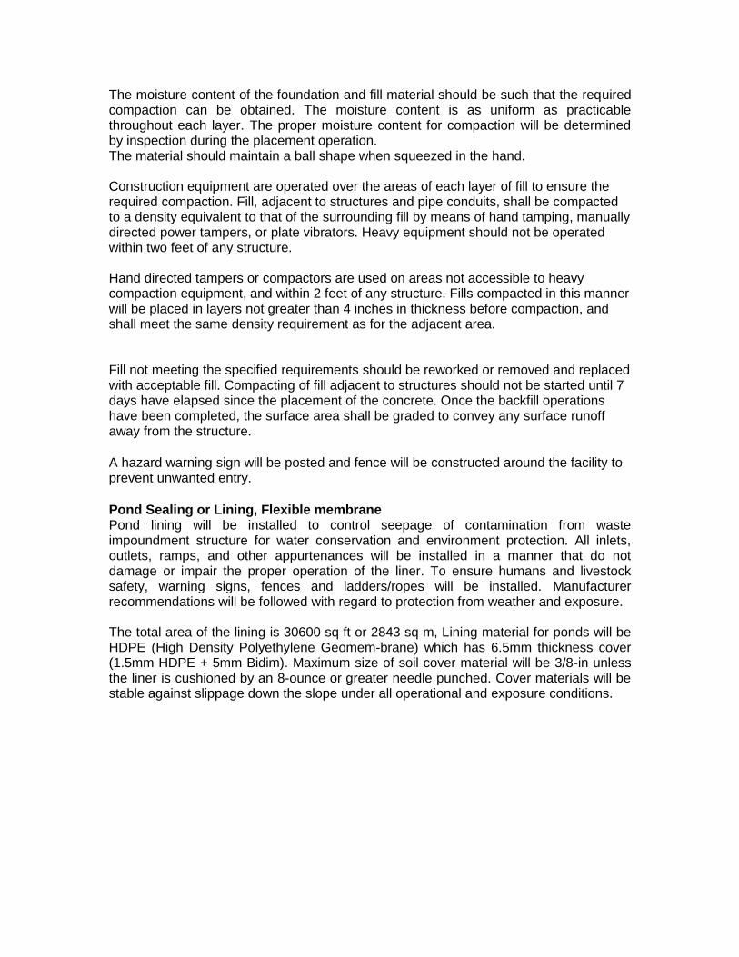
The moisture content of the foundation and fill material should be such that the required compaction can be obtained. The moisture content is as uniform as practicable throughout each layer. The proper moisture content for compaction will be determined by inspection during the placement operation. The material should maintain a ball shape when squeezed in the hand. Construction equipment are operated over the areas of each layer of fill to ensure the required compaction. Fill, adjacent to structures and pipe conduits, shall be compacted to a density equivalent to that of the surrounding fill by means of hand tamping, manually directed power tampers, or plate vibrators. Heavy equipment should not be operated within two feet of any structure. Hand directed tampers or compactors are used on areas not accessible to heavy compaction equipment, and within 2 feet of any structure. Fills compacted in this manner will be placed in layers not greater than 4 inches in thickness before compaction, and shall meet the same density requirement as for the adjacent area. Fill not meeting the specified requirements should be reworked or removed and replaced with acceptable fill. Compacting of fill adjacent to structures should not be started until 7 days have elapsed since the placement of the concrete. Once the backfill operations have been completed, the surface area shall be graded to convey any surface runoff away from the structure. A hazard warning sign will be posted and fence will be constructed around the facility to prevent unwanted entry. Pond Sealing or Lining, Flexible membrane Pond lining will be installed to control seepage of contamination from waste impoundment structure for water conservation and environment protection. All inlets, outlets, ramps, and other appurtenances will be installed in a manner that do not damage or impair the proper operation of the liner. To ensure humans and livestock safety, warning signs, fences and ladders/ropes will be installed. Manufacturer recommendations will be followed with regard to protection from weather and exposure. The total area of the lining is 30600 sq ft or 2843 sq m, Lining material for ponds will be HDPE (High Density Polyethylene Geomem-brane) which has 6.5mm thickness cover (1.5mm HDPE + 5mm Bidim). Maximum size of soil cover material will be 3/8-in unless the liner is cushioned by an 8-ounce or greater needle punched. Cover materials will be stable against slippage down the slope under all operational and exposure conditions.
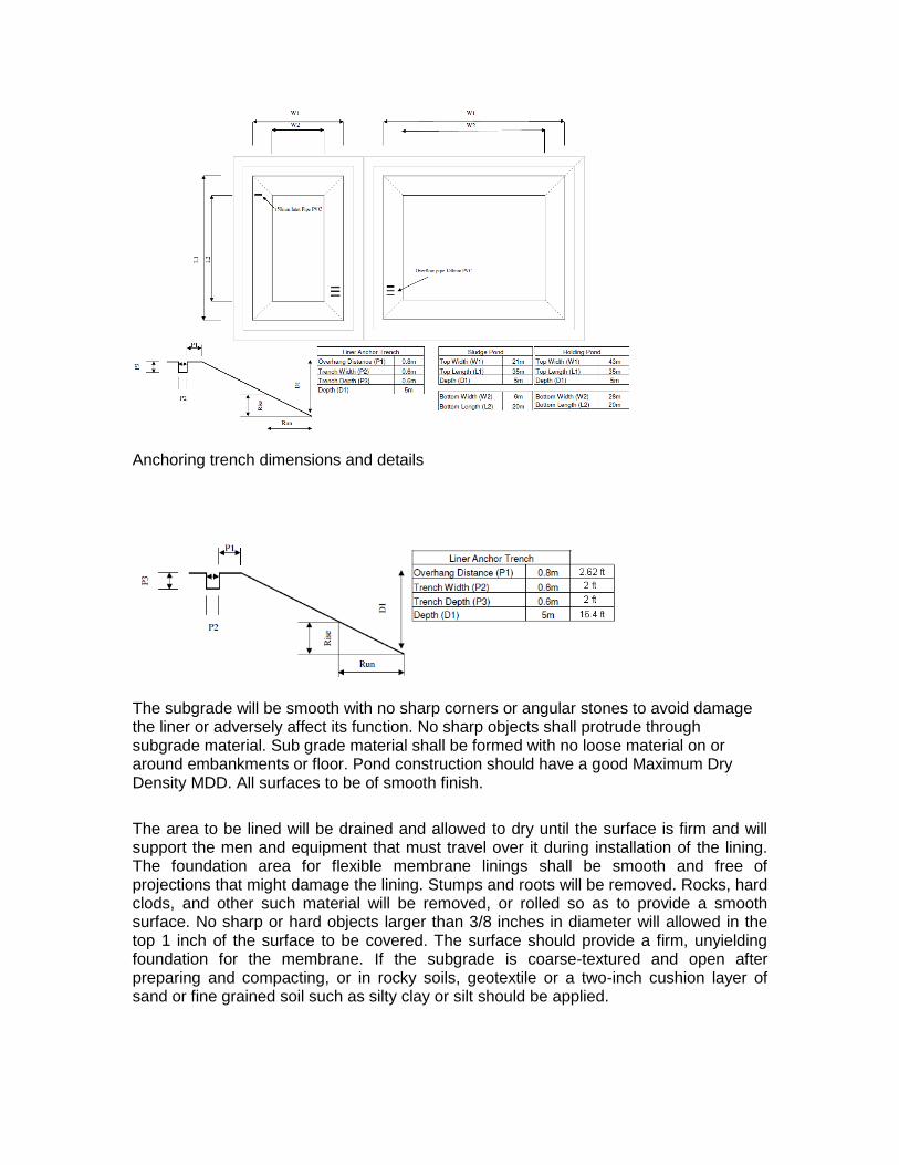
Anchoring trench dimensions and details
The subgrade will be smooth with no sharp corners or angular stones to avoid damage the liner or adversely affect its function. No sharp objects shall protrude through subgrade material. Sub grade material shall be formed with no loose material on or around embankments or floor. Pond construction should have a good Maximum Dry Density MDD. All surfaces to be of smooth finish.
The area to be lined will be drained and allowed to dry until the surface is firm and will support the men and equipment that must travel over it during installation of the lining. The foundation area for flexible membrane linings shall be smooth and free of projections that might damage the lining. Stumps and roots will be removed. Rocks, hard clods, and other such material will be removed, or rolled so as to provide a smooth surface. No sharp or hard objects larger than 3/8 inches in diameter will allowed in the top 1 inch of the surface to be covered. The surface should provide a firm, unyielding foundation for the membrane. If the subgrade is coarse-textured and open after preparing and compacting, or in rocky soils, geotextile or a two-inch cushion layer of sand or fine grained soil such as silty clay or silt should be applied.
All lining material should be free of damage or defect. Membranes will be carefully spread over the subgrade so they lie in a relaxed state. Polyethylene film requires about 5 percent slack for satisfactory results. Backfill in anchor trench will be compacted to a density equivalent to that of the surrounding area. All field splices will be made in accordance with the manufacturer's recommended technique, using materials furnished for the purpose. The joints will be watertight and maintain its integrity through the expected life of the lining. The maximum particle size of soil cover material will be 3/8-inch unless the liner is cushioned by an 8-ounce or greater needle punched, non-woven geotextile padding material. The cover shall be placed to the specified depth without damage to the membrane.
The liner installation will be complete with product panel placement, seam placement and test results. As the liner is fabricated on site the information is documented post install. A standard Quality assurance is completed post installation. This Q A includes.
Material type/size/date deployed and roll number
Technician details
Subgrade material acceptance
Trial weld log including shear/peel testing and machine settings
Panel Placement log including pipe boots/attachments/appurtenances
Non-destructive Testing reports (seam tested welds )
Repair report logged in diagram also in panel log
Completion Certificate
Warranty Certificate
Nutrient Management We assume that Kikuyu grass producing 50 MT DM requires 800 kg of nitrogen per hectare per year. All the manure which is collected at farm is applied on the pastures within limits that do not exceed nitrogen demand of the plant. Effluent is applied on grazing land significantly below the limits of nutrient loading. The soil type is free draining volcanic soil and therefore its rest period from rain can be as little as 6 hours before it can be irrigated, if rainfall is greater than 6mm/hour for periods of greater than 3 hours the soil will be too wet to irrigate effluent.
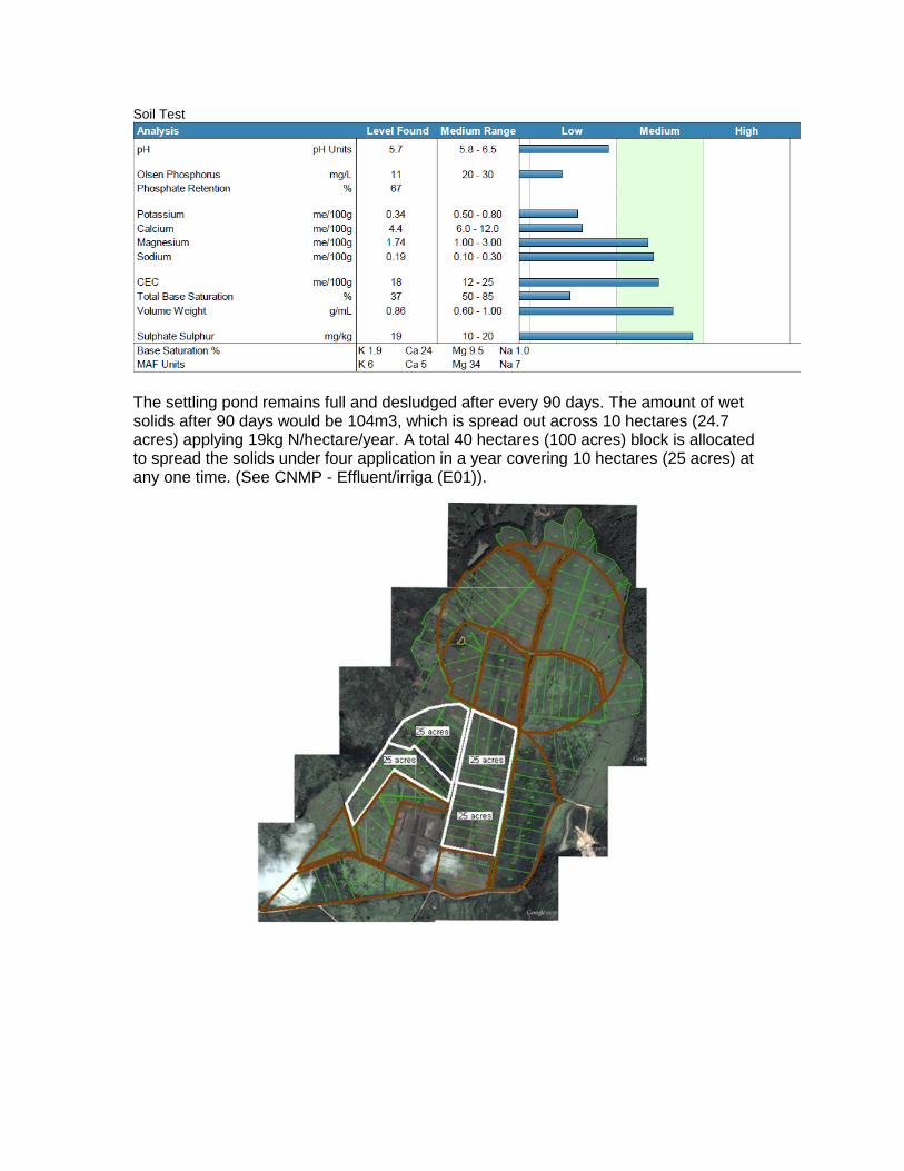
Soil Test
The settling pond remains full and desludged after every 90 days. The amount of wet solids after 90 days would be 104m3, which is spread out across 10 hectares (24.7 acres) applying 19kg N/hectare/year. A total 40 hectares (100 acres) block is allocated to spread the solids under four application in a year covering 10 hectares (25 acres) at any one time. (See CNMP - Effluent/irriga (E01)).
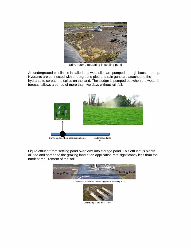
Stirrer pump operating in settling pond
An underground pipeline is installed and wet solids are pumped through booster pump. Hydrants are connected with underground pipe and rain guns are attached to the hydrants to spread the solids on the land. The sludge is pumped out when the weather forecast allows a period of more than two days without rainfall.
Liquid effluent from settling pond overflows into storage pond. This effluent is highly diluted and spread to the grazing land at an application rate significantly less than the nutrient requirement of the soil.
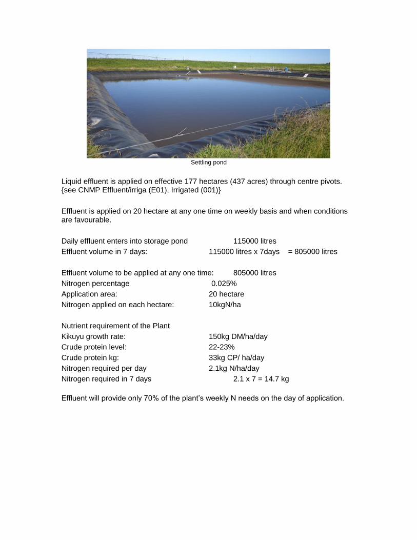
Settling pond
Liquid effluent is applied on effective 177 hectares (437 acres) through centre pivots. {see CNMP Effluent/irriga (E01), Irrigated (001)}
Effluent is applied on 20 hectare at any one time on weekly basis and when conditions are favourable.
Daily effluent enters into storage pond 115000 litres
Effluent volume in 7 days: 115000 litres x 7days = 805000 litres
Effluent volume to be applied at any one time: 805000 litres
Nitrogen percentage 0.025%
Application area: 20 hectare
Nitrogen applied on each hectare: 10kgN/ha
Nutrient requirement of the Plant
Kikuyu growth rate: 150kg DM/ha/day
Crude protein level: 22-23%
Crude protein kg: 33kg CP/ ha/day
Nitrogen required per day 2.1kg N/ha/day
Nitrogen required in 7 days 2.1 x 7 = 14.7 kg
Effluent will provide only 70% of the plant’s weekly N needs on the day of application.
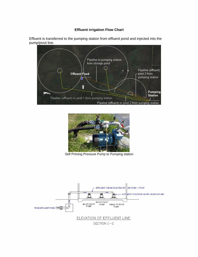
Effluent irrigation Flow Chart
Effluent is transferred to the pumping station from effluent pond and injected into the pump/pivot line.
Self Priming Pressure Pump to Pumping station
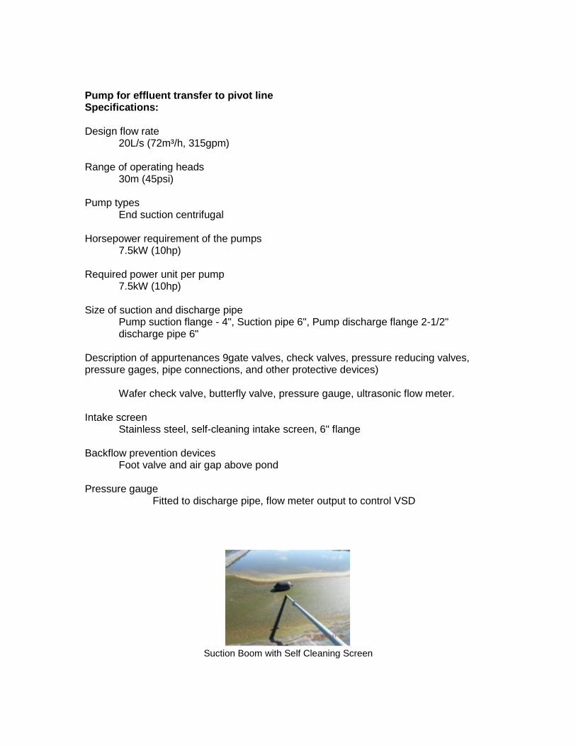
Pump for effluent transfer to pivot line Specifications: Design flow rate
20L/s (72m³/h, 315gpm) Range of operating heads
30m (45psi) Pump types
End suction centrifugal Horsepower requirement of the pumps 7.5kW (10hp) Required power unit per pump
7.5kW (10hp)
Size of suction and discharge pipe Pump suction flange - 4", Suction pipe 6", Pump discharge flange 2-1/2" discharge pipe 6"
Description of appurtenances 9gate valves, check valves, pressure reducing valves, pressure gages, pipe connections, and other protective devices)
Wafer check valve, butterfly valve, pressure gauge, ultrasonic flow meter. Intake screen Stainless steel, self-cleaning intake screen, 6" flange Backflow prevention devices Foot valve and air gap above pond Pressure gauge
Fitted to discharge pipe, flow meter output to control VSD
Suction Boom with Self Cleaning Screen
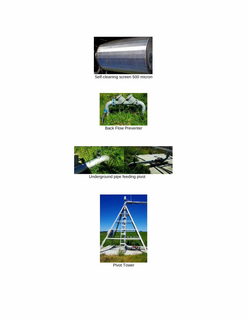
Self-cleaning screen 500 micron
Back Flow Preventer
Underground pipe feeding pivot
Pivot Tower
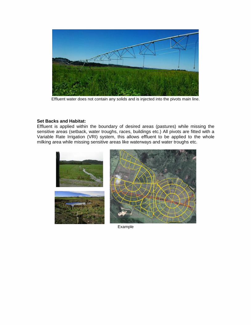
Effluent water does not contain any solids and is injected into the pivots main line.
Set Backs and Habitat: Effluent is applied within the boundary of desired areas (pastures) while missing the sensitive areas (setback, water troughs, races, buildings etc.) All pivots are fitted with a Variable Rate Irrigation (VRI) system, this allows effluent to be applied to the whole milking area while missing sensitive areas like waterways and water troughs etc.
Example