Harwin Product Catalog - ClarkeM225 - XXX 00 46 TYPE 253 Female Crimp 22-24 AWG, Reeled 254 Female...
18
218 www.harwin.com 2mm (.079") PITCH 218 M225 Connectors Current rating of 3A per signal contact (all electrically loaded; 3.3A per individual contact) Female crimp contacts on continuous strip for automated crimping Polarized and fully shrouded housings to prevent accidental damage Increased operating temperature range: -55°C to +125°C Simple locking mechanism – push fixing pin fully home to expand and lock the rubber collar into the male connector Suitable for 22 to 28AWG PTFE equipment cables 2.00mm pitch high performance industrial connector range. Available in a selection of crimp sizes and pin counts, this cable-to-board system gives a more robust connection than the M22 series. The three points of contact on the female crimp contact enable resistance against industrial levels of vibration and shock. Added strain relief and vibration resistance is obtained with the use of the rubber locking collars and fixing pin system. Industrial: factory and mobile machinery, control panels and sus-systems, drives, robotics and other automation Instrumentation: test equipment and portable hand-held devices Site Control: remote control devices, ground and machinery monitoring M225 Series Connectors provide an excellent connection system for demanding industrial environments: Specifications Materials Mouldings, Pins: High Temperature Plastic, UL94V-0 Contacts Female: Beryllium Copper, Tin finish Male: Phosphor Bronze, Tin finish Rubber Locking Collar: Fluoroelastic Polymer Electrical Current Individual contacts in isolation: 3.3A max (at 25°C) 2.6A max (at 85°C) All contacts simultaneously: 3.0A max (at 25°C) 2.2A max (at 85°C) Working voltage: 800V DC or AC peak Voltage proof: 1,200V DC or AC peak Contact resistance: 25mΩ max Insulation resistance: 100MΩ min Mechanical Durability: 50 operations Insertion force (max): 2.8N per contact Withdrawal force (min): 0.2N per contact Environmental Environmental classification: 55/125/56 days at 95% RH Operational temperature: -55°C to +125°C *Vibration sensitivity: 10Hz to 20000Hz, 0.75mm, 98m/s 2 (10G), duration 6 hours *Bump severity: 390m/s 2 (40G), 4000 ±10 bumps *Shock severity: 981m/s 2 (100G), for 6ms *Acceleration severity: 490m/s 2 (50G) * Tested with fixing pins fully engaged Pin Numbering Mating Profile FEMALE MALE No. 1 contact mark No. 1 contact mark 13.34 max Clarke & Severn Electronics Ph +612 9482 1944 Email [email protected] www.clarke.com.au
Transcript of Harwin Product Catalog - ClarkeM225 - XXX 00 46 TYPE 253 Female Crimp 22-24 AWG, Reeled 254 Female...

218www.harwin.com
2mm
(.07
9")
PITC
H
218
M225 Connectors
Current rating of 3A per signal contact (all electrically loaded; 3.3A per individual contact)
Female crimp contacts on continuous strip for automated crimping
Polarized and fully shrouded housings to prevent accidental damage
Increased operating temperature range: -55°C to +125°C
Simple locking mechanism – push fixing pin fully home to expand and lock the rubber collar into the male connector
Suitable for 22 to 28AWG PTFE equipment cables
2.00mm pitch high performance industrial connector range. Available in a selection of crimp sizes and pin counts, this cable-to-board system gives a more robust connection than the M22 series. The three points of contact on the female crimp contact enable resistance against industrial levels of vibration and shock. Added strain relief and vibration resistance is obtained with the use of the rubber locking collars and fixing pin system.
Industrial: factory and mobile machinery, control panels and sus-systems, drives, robotics and other automation
Instrumentation: test equipment and portable hand-held devices
Site Control: remote control devices, ground and machinery monitoring
M225 Series Connectors provide an excellent connection system for demanding industrial environments:
Specifications Materials
Mouldings, Pins: High Temperature Plastic, UL94V-0Contacts
Female: Beryllium Copper, Tin finish Male: Phosphor Bronze, Tin finish
Rubber Locking Collar: Fluoroelastic Polymer
Electrical
Current Individual contacts in isolation: 3.3A max (at 25°C)
2.6A max (at 85°C) All contacts simultaneously: 3.0A max (at 25°C)
2.2A max (at 85°C)Working voltage: 800V DC or AC peakVoltage proof: 1,200V DC or AC peakContact resistance: 25mΩ maxInsulation resistance: 100MΩ min
Mechanical
Durability: 50 operationsInsertion force (max): 2.8N per contactWithdrawal force (min): 0.2N per contact
Environmental
Environmental classification: 55/125/56 days at 95% RHOperational temperature: -55°C to +125°C*Vibration sensitivity: 10Hz to 20000Hz, 0.75mm,
98m/s2 (10G), duration 6 hours*Bump severity: 390m/s2 (40G), 4000 ±10 bumps*Shock severity: 981m/s2 (100G), for 6ms*Acceleration severity: 490m/s2 (50G)
* Tested with fixing pins fully engaged
Pin Numbering Mating ProfileFEMALE MALE
No. 1contact
mark
No. 1 contact mark
13.34 max
Clarke & Severn Electronics Ph +612 9482 1944 Email [email protected] www.clarke.com.au

M225 Connectors
219www.harwin.com
Female Crimp Housings Female crimp housing kits - contacts are ordered separately (shown on following page).
Housings are supplied fitted with the rubber locking collars, and supplied with loose fixing pins. Collars and pins only needed to be ordered separately if spares are required.
2mm
(.079") PITCH
All dimensions in mm.
HOUSING SPARE RUBBER LOCKING COLLAR
SPARE FIXING PIN
CALCULATIONA B + 12
B Total no. of contacts - 2
C B + 7
HOW TO ORDER
M225 - 455 XX 98
SERIES CODE NO. OF CONTACTS10, 20, 26, 34, 50
B
2.00
11.11 max
No. 1 contact
C
9.70
2.50Ø4.00
5.60 maxA
ORDER CODEM225-0500098
ORDER CODEM225-0600098
Housing Kit includes 2 x Rubber Locking Collars (fitted) and 2 x Fixing Pins (loose).

220www.harwin.com
2mm
(.07
9")
PITC
H
All dimensions in mm.
Crimp contacts must be ordered separately, see previous pages for applicable housings.
Crimp contacts are available loose, or in continuous reeled format for automated crimping.
Female Crimp Contacts
M225 Connectors
CRIMP CONTACTS HAND CRIMP TOOL
REMOVAL TOOL
2.70-3.00
Ø1.10 max
Reeled
HOW TO ORDER
M225 - XXX 00 46
TYPE253 Female Crimp 22-24 AWG, Reeled
254 Female Crimp 26-28 AWG, Reeled
283 Female Crimp 22-24 AWG, Loose
284 Female Crimp 26-28 AWG, Loose
SERIES CODE
FINISH46 Tin
14.18
Loose
10.20
WIRE STRIPPING DETAIL
ORDER CODEZ80-258
For removal of crimped contacts from mouldings. Instruction sheet available at
www.harwin.com/instructions.
Instruction sheet available at www.harwin.com/instructions.
ORDER CODEZ80-255

M225 Connectors
221www.harwin.com
Male Vertical PC Tail Polarised mouldings. Fully shrouded contacts.
2mm
(.079") PITCH
All dimensions in mm.
M225 - 520 XX 46
SERIES CODEFINISH46 Tin
TOTAL NO. OF CONTACTS10, 20, 26, 34, 50
HOW TO ORDER
MALE CALCULATIONA B + 12
B Total no. of contacts - 2
C B + 7
B
5.55No. 1 contact
C
0.50
5.60
2.00
2.003.30
Ø0.50
A
Recommended PC Board Pattern
2.002.00
B
Ø0.65-0.75
222
2mm
(.07
9")
PITC
H
All dimensions in mm.
www.harwin.com
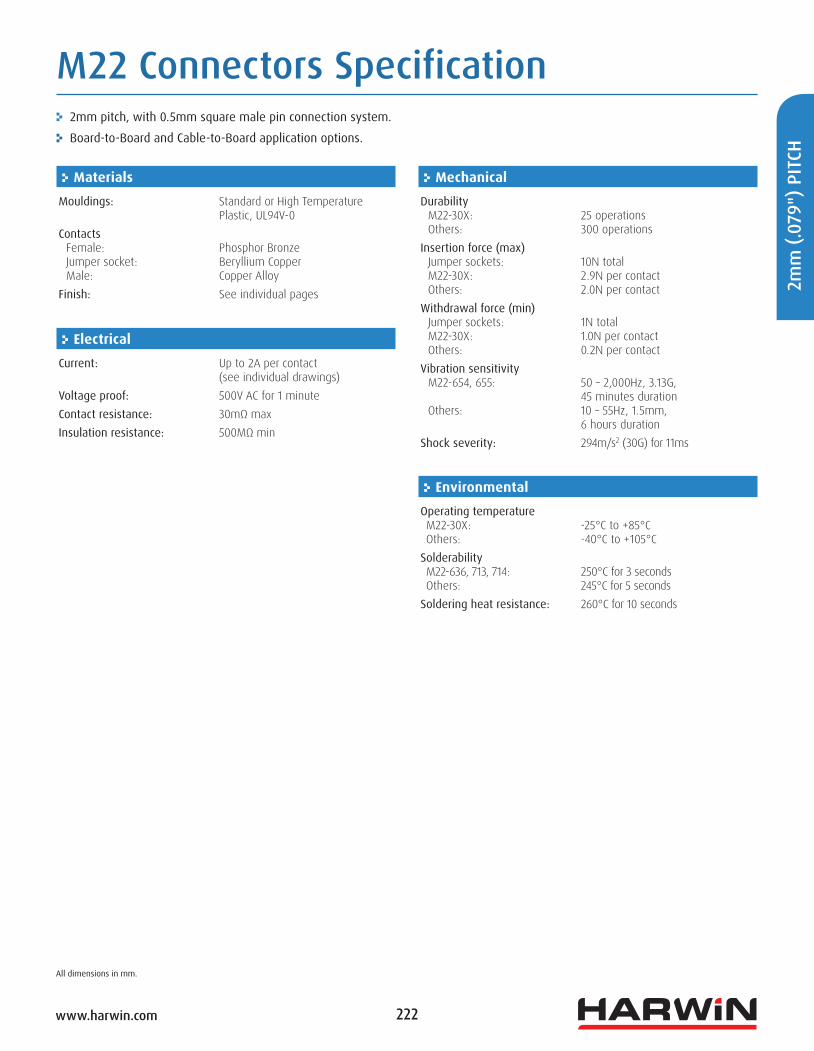
M22 Connectors Specification
Materials
Mouldings: Standard or High Temperature Plastic, UL94V-0
Contacts Female: Phosphor Bronze Jumper socket: Beryllium Copper Male: Copper AlloyFinish: See individual pages
Electrical
Current: Up to 2A per contact (see individual drawings) Voltage proof: 500V AC for 1 minuteContact resistance: 30mΩ maxInsulation resistance: 500MΩ min
Mechanical
Durability M22-30X: 25 operations Others: 300 operationsInsertion force (max) Jumper sockets: 10N total M22-30X: 2.9N per contact Others: 2.0N per contactWithdrawal force (min) Jumper sockets: 1N total M22-30X: 1.0N per contact Others: 0.2N per contactVibration sensitivity M22-654, 655: 50 – 2,000Hz, 3.13G, 45 minutes duration Others: 10 – 55Hz, 1.5mm,
6 hours durationShock severity: 294m/s2 (30G) for 11ms
Environmental
Operating temperature M22-30X: -25°C to +85°C Others: -40°C to +105°CSolderability M22-636, 713, 714: 250°C for 3 seconds Others: 245°C for 5 secondsSoldering heat resistance: 260°C for 10 seconds
2mm pitch, with 0.5mm square male pin connection system.
Board-to-Board and Cable-to-Board application options.

223
2mm
(.079") PITCH
www.harwin.com
All dimensions in mm.
M22 Connectors Mating ProfilesFEMALE
VERTICAL PC TAIL VERTICAL SMT
VERTICAL SMT Low Profile HORIZONTAL SMT CRIMP
SIL DIL DIL DIL SIL DIL SIL DIL
MAL
E
VERT
ICAL
PC
TAIL
HORI
ZON
TAL
PC T
AIL
VERT
ICAL
SM
TVE
RTIC
AL S
MT
With
Peg
sHO
RIZO
NTA
L SM
T
5.90 5.80 5.80 3.60 9.10 max
9.10 max
13.10 max
11.00 max7.359.559.55
7.65
6.80 6.80 4.60 10.40 max
16.02 max
12.60 max
10.3212.5212.529.20
10.6513.95
12.40 17.70
14.95
14.70
20.4113.69
6.55 6.55 4.35 10.00 max
224www.harwin.com
2mm
(.07
9")
PITC
H
All dimensions in mm.
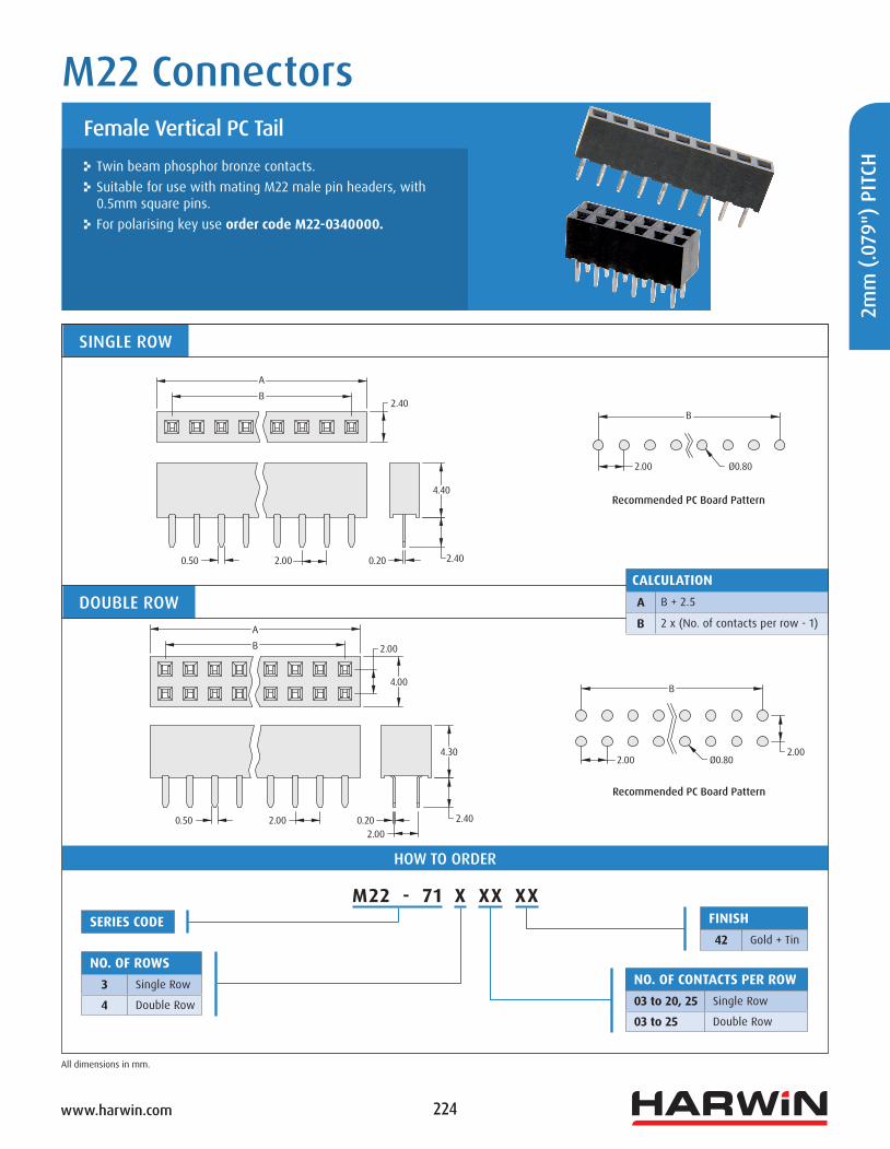
Twin beam phosphor bronze contacts. Suitable for use with mating M22 male pin headers, with 0.5mm square pins.
For polarising key use order code M22-0340000.
Female Vertical PC Tail
M22 Connectors
SINGLE ROW
HOW TO ORDER
DOUBLE ROW
Recommended PC Board Pattern
CALCULATIONA B + 2.5
B 2 x (No. of contacts per row - 1)
M22 - 71 X XX XXSERIES CODE
NO. OF ROWS3 Single Row
4 Double Row
NO. OF CONTACTS PER ROW03 to 20, 25 Single Row
03 to 25 Double Row
Recommended PC Board Pattern
FINISH42 Gold + Tin
2.40
4.40
2.40
0.202.000.50
AB 2.00
4.00
0.50 2.00 0.20
2.00 Ø0.802.00
2.00
4.30
2.40
B
AB
B
2.00 Ø0.80

225www.harwin.com
2mm
(.079") PITCH
All dimensions in mm.
Dual entry sockets - can be used as either a top entry or bottom entry configuration.
The low profile socket has locating pegs, to assist with correct positioning and minimised movement during soldering.
Twin beam contact for cost-effective reliability. Contact [email protected] for Tape and Reel options.
Female Vertical Surface Mount, Dual Entry
M22 Connectors
Recommended PC Board Pattern
4.30mm HIGH CALCULATIONA B + 2.5
B 2 x (No. of contacts per row - 1)
2.10mm HIGH CALCULATIONA 2 x No. of contacts per row
B 2 x (No. of contacts per row - 1)
C B – 2
HOW TO ORDER
M22 - 63 X XX XX
SERIES CODE
TYPE4 4.30mm high
6 2.10mm highNO. OF CONTACTS PER ROW03 to 20 4.30mm high
02 to 20 2.10mm high
FINISH42 Gold + Tin
46 Tin (2.10mm high only)
Recommended PC Board Pattern
2.00
4.50
2.000.50A
4.30
2.00
0.89 2.00 2.10
7.40
Ø1.00
6.20
B2.00
4.00
2.000.50
2.10
0.90
2.00
BC
2.00 1.65
6.80
0.89 Ø1.00 Ø0.856.00
B
B
A
C

226www.harwin.com
2mm
(.07
9")
PITC
H
All dimensions in mm.
Rear tail configuration, to allow mounting right up to the edge of the PCB.
Supplied in Tape and Reel packaging as standard for use in automated assembly systems.
Female Horizontal Surface Mount
M22 Connectors
SINGLE ROW DOUBLE ROWCALCULATIONA B + 2.3
B 2 x (No. of contacts per row - 1)
HOW TO ORDER
M22 - 65 X XX XX R
SERIES CODE
TYPE4 Single Row
5 Double RowNO. OF CONTACTS PER ROW02 to 06, 08, 10
CALCULATIONA B + 2.3
B 2 x (No. of contacts per row - 1)
FINISH42 Gold + Tin
PACKAGINGR Tape & Reeled
Recommended PC Board Pattern Recommended PC Board Pattern
B
2.00 0.50 square
6.35
2.80
1.00
2.00
A
B
2.00 2.00
1.00
0.50 square2.00
2.004.00
2.00
B
A
2.001.00
5.30
6.35
6.10
2.80
2 x 1.00

227www.harwin.com
2mm
(.079") PITCH
All dimensions in mm.
Female crimp housing - contacts are ordered separately (shown on following page).
For polarising key use order code M22-0340000.
Female Crimp Housings
M22 Connectors
SINGLE ROW DOUBLE ROWCALCULATIONA B + 2.3
B 2 x (No. of contacts per row - 1)
HOW TO ORDER
M22 - 30 X XX 00SERIES CODE
TYPE1 Single Row
2 Double Row
NO. OF CONTACTS PER ROW02 to 20
CALCULATIONA B + 2.2
B 2 x (No. of contacts per row - 1)
B
A
2.00
2.00
7.20
2.00
2.00
4.00A
B
7.20

228www.harwin.com
2mm
(.07
9")
PITC
H
All dimensions in mm.
Loose or reeled contacts. Open crimp design, ideal for automation. Use with female crimp housings shown on previous page. Suitable for connection with male pin headers with a mating length of 4.00mm or longer.
Female Crimp Contacts
M22 Connectors
CONTACTS HAND CRIMP TOOL
HOW TO ORDER
M22 - 30 X 00 XX
TYPE4 Reeled Contacts
5 Loose Contacts
FINISH42 Gold
46 Tin
WIRE STRIPPING DETAILS
ORDER CODEZ22-020
Reeled (continuous strip) Order code is for one reel of 10,000 contacts.
Instruction sheet is available at www.harwin.com/instructions. For use with loose contacts.
Loose (cropped) Order code is for one pack of 100 contacts.
SERIES CODE
5.50
9.64
6.00 Ø1.40 max 24 to 30 AWG
1.00 to 1.50

229www.harwin.com
2mm
(.079") PITCH
All dimensions in mm.
HOW TO ORDER
Can be fitted and removed by hand. Used with male pin headers, Jumper Sockets give an alternative on-board programming method to DIP switches.
Jumper Sockets have an open top for use with test probes.
Jumper Sockets, Polarising Key
M22 Connectors
JUMPER SOCKET POLARISING KEY
For use with Female Vertical PC Tail connectors, M22-713 and M22-714 series.
For use with Female Cable Housings, M22-301 and M22-302 series.
M22 - 19 X 00 XX
SERIES CODE
COLOUR0 Black
1 Blue
2 Red
3 Grey
FINISH05 Gold
46 Tin
ORDER CODEM22-0340000
3.85
1.30
3.35 1.68 Ø0.55 max
2.60
3.45
2.00
1.93
Exposed contact for probing

230www.harwin.com
2mm
(.07
9")
PITC
H
All dimensions in mm.
M22 Connectors
Suitable for use with female PCB connectors and jumper sockets. 4.2mm mating pin length recommended for use with female cable connections.
Pin headers can be cut into smaller sizes. Also available with variable dimensions.
Male Vertical PC Tail
SINGLE ROW
DOUBLE ROWCALCULATIONA 2 x No. of contacts per row
B 2 x (No. of contacts per row - 1)
HOW TO ORDER
M22 - 2XX XX XX
SERIES CODE
NO. OF CONTACTS PER ROW02 to 25, 50 M22-201, M22-202
02 to 20, 25, 40, 50 M22-251
02 to 20, 25, 40 M22-252
02 to 20 M22-271, M22-272
TYPESINGLE ROW DOUBLE ROW MATING LENGTH TAIL
201 202 3.50mm 3.40mm
251 252 3.50mm 2.30mm
271 272 4.20mm 2.30mm
FINISH05 Gold
46 Tin
AB
2.00
B
2.00
2.00
4.00
1.50
A
1.50
2.00
0.50 square
0.50 square
Tail
Mating Length
Tail
2.00 Ø0.802.00
B
B
2.00 Ø0.80
Mating Length
Recommended PC Board Pattern
Recommended PC Board Pattern
231www.harwin.com
2mm
(.079") PITCH
All dimensions in mm.
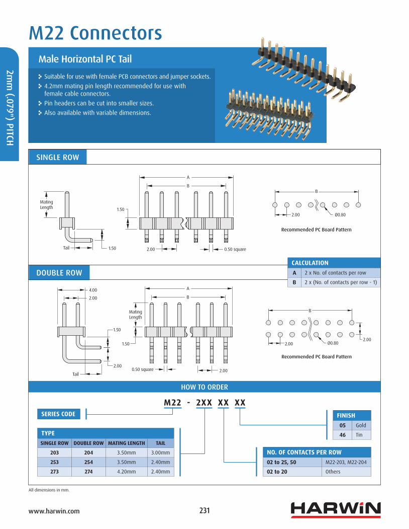
Suitable for use with female PCB connectors and jumper sockets. 4.2mm mating pin length recommended for use with female cable connectors.
Pin headers can be cut into smaller sizes. Also available with variable dimensions.
Male Horizontal PC Tail
M22 Connectors
SINGLE ROW
DOUBLE ROWCALCULATIONA 2 x No. of contacts per row
B 2 x (No. of contacts per row - 1)
HOW TO ORDER
M22 - 2XX XX XXSERIES CODE
TYPESINGLE ROW DOUBLE ROW MATING LENGTH TAIL
203 204 3.50mm 3.00mm
253 254 3.50mm 2.40mm
273 274 4.20mm 2.40mm
NO. OF CONTACTS PER ROW02 to 25, 50 M22-203, M22-204
02 to 20 Others
FINISH05 Gold
46 Tin
2.00 0.50 square
B
A
1.50
1.50Mating Length
Tail
4.00
2.00
1.50
1.50
2.00
Tail
Mating Length
A
B
0.50 square 2.00
B
2.00 Ø0.80
2.00 Ø0.802.00
B
Recommended PC Board Pattern
Recommended PC Board Pattern
232www.harwin.com
2mm
(.07
9")
PITC
H
All dimensions in mm.
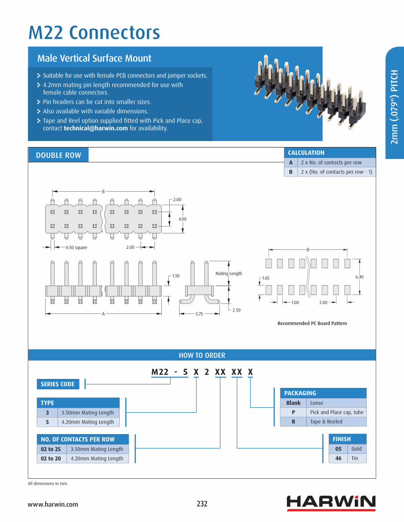
Suitable for use with female PCB connectors and jumper sockets. 4.2mm mating pin length recommended for use with female cable connectors.
Pin headers can be cut into smaller sizes. Also available with variable dimensions. Tape and Reel option supplied fitted with Pick and Place cap, contact [email protected] for availability.
Male Vertical Surface Mount
M22 Connectors
DOUBLE ROW CALCULATIONA 2 x No. of contacts per row
B 2 x (No. of contacts per row - 1)
HOW TO ORDER
M22 - 5 X 2 XX XX XSERIES CODE
TYPE3 3.50mm Mating Length
5 4.20mm Mating Length
NO. OF CONTACTS PER ROW02 to 25 3.50mm Mating Length
02 to 20 4.20mm Mating Length
FINISH05 Gold
46 Tin
PACKAGINGBlank Loose
P Pick and Place cap, tube
R Tape & Reeled
Recommended PC Board Pattern
Mating Length
0.50 square 2.00
2.00
4.00
1.50
5.752.50
2.001.00
1.65 6.40
B
B
A

233www.harwin.com
2mm
(.079") PITCH
All dimensions in mm.
Suitable for use with female PCB connectors and jumper sockets.
Supplied with location pegs for additional placement accuracy. Tape and Reel option supplied fitted with Pick and Place cap.
Male Vertical Surface Mount
M22 Connectors
DOUBLE ROW CALCULATIONA 2 x No. of contacts per row
B 2 x (No. of contacts per row - 1)
C B – 2
HOW TO ORDER
M22 - 530 XX 05 X
SERIES CODE
NO. OF CONTACTS PER ROW02 to 06, 10 Loose
02, 03, 05 Tape & ReeledFINISH05 Gold
PACKAGINGBlank Loose
R Tape & Reeled
Recommended PC Board Pattern
0.50 square
B
C
A
2.00
1.50
2.00
4.003.50
2.25
1.00
5.75
1.02 2.00
6.75
2.40
B
C
Ø1.20
2.00

234www.harwin.com
2mm
(.07
9")
PITC
H
All dimensions in mm.
Suitable for use with female PCB connectors and jumper sockets. 4.2mm mating pin length recommended for use with female cable connectors.
Single row pin headers can be cut into smaller sizes. Locating pegs on double row, to assist with correct positioning and minimised movement during soldering.
Contact [email protected] for Tape and Reel options.
Male Horizontal Surface Mount
M22 Connectors
Recommended PC Board Pattern
SINGLE ROW CALCULATIONA 2 x No. of contacts per row
B 2 x (No. of contacts per row - 1)
DOUBLE ROW CALCULATIONA 2 x No. of contacts per row
B 2 x (No. of contacts per row - 1)
C B – 2
HOW TO ORDER
M22 - 5 X 3 XX 05
NO. OF CONTACTS PER ROW02 to 15 M22-533
03 to 15, 20 M22-543
03 to 20 M22-563
SERIES CODE
TYPE3 Single Row
4 Double Row, 3.2mm Mating Length
6 Double Row, 4.2mm Mating Length
FINISH05 Gold
Recommended PC Board Pattern
2.80
2.00
2.00
Ø1.00
Ø1.20
B
A
0.50 square 2.00
2.00
2.00
4.20 2.80
1.27
2.000.89
B
A
CB
0.50 square 2.00
1.00
6.22
Mating Length
4.00
1.271.27
2.03
0.89 2.00
5.45
1.93C
B
2.03

235www.harwin.com
2mm
(.079") PITCH
All dimensions in mm.
If you are unable to specify the connector you require from our standard range of M22 connectors, use the order code below to create an application-specific connector.
Contact [email protected] for further information, or search online for M22-XXX.
Suitable for use with female connectors shown on previous pages.
Pin Header Variants
M22 Connectors
TERMINATION STYLES
HOW TO ORDER
M22 - XXX XXX X XX XX
NO. OF CONTACTS PER ROW02 to 50
FINISH05 Gold
46 Tin
Vertical PC Tail Pin section is 0.50mm square.
PCB mounting hole is Ø0.80mm.
V Series W Series Horizontal PC Tail Pin section is 0.50mm square.
PCB mounting hole is Ø0.80mm.
Maximum B dimension is 6.00mm.
H Series J Series
Extended PC Tail Pin section is 0.50mm square.
PCB mounting hole is Ø0.80mm.
E Series (3mm Tail)K Series (2.4mm Tail)
F Series (3mm Tail)L Series (2.4mm Tail)
Vertical SMT Extended SMT Pin section is 0.50mm square.
For PCB pad layout see standard Male SMT pin header.
B dimension is 000 on S series.
S Series T Series
SERIES CODE
DIMENSION AExample: 7.8mm = 078
DIMENSION BExample: 5.0mm = 050
SINGLE ROW DOUBLE ROWV W Vertical
H J Horizontal
E F Extended
K L Extended (2.4mm Tail)
– S Surface Mount
– T Extended Surface Mount
2.00A
B
Tail
1.50
A
B
2.00
1.50
4.00
A
B
2.00
1.50
4.00
1.501.50
A 2.00
B
1.50
2.00
4.00
1.50
Tail2.00
A
B
1.50
2.00 A
B
4.002.00
1.50
1.50
4.002.00
1.255.75
A
A
B5.75 0.70