Harvester Operation and Service...
25
1 Before Setting Up Your Harvester . . . . . . . . . . . . . . . . . . . . . . . . . . . . . . . . . . . . . . . . . . . . . . . . . .3 Parts List . . . . . . . . . . . . . . . . . . . . . . . . . . . . . . . . . . . . . . . . . . . . . . . . . . . . . . . . . . . . . . . . . . . . .3 Requirements . . . . . . . . . . . . . . . . . . . . . . . . . . . . . . . . . . . . . . . . . . . . . . . . . . . . . . . . . . . . . . . . .3 Harvester Installation . . . . . . . . . . . . . . . . . . . . . . . . . . . . . . . . . . . . . . . . . . . . . . . . . . . . . . . . . . .4 Wash Installation . . . . . . . . . . . . . . . . . . . . . . . . . . . . . . . . . . . . . . . . . . . . . . . . . . . . . . . . . . . . . .5 Vacuum Installation . . . . . . . . . . . . . . . . . . . . . . . . . . . . . . . . . . . . . . . . . . . . . . . . . . . . . . . . . . . .6 Operation . . . . . . . . . . . . . . . . . . . . . . . . . . . . . . . . . . . . . . . . . . . . . . . . . . . . . . . . . . . . . . . . . . . .8 Adjustments . . . . . . . . . . . . . . . . . . . . . . . . . . . . . . . . . . . . . . . . . . . . . . . . . . . . . . . . . . . . . . . . .10 Options . . . . . . . . . . . . . . . . . . . . . . . . . . . . . . . . . . . . . . . . . . . . . . . . . . . . . . . . . . . . . . . . . . . . .15 Tubing . . . . . . . . . . . . . . . . . . . . . . . . . . . . . . . . . . . . . . . . . . . . . . . . . . . . . . . . . . . . . . . . . . . . . .20 General Maintenance . . . . . . . . . . . . . . . . . . . . . . . . . . . . . . . . . . . . . . . . . . . . . . . . . . . . . . . . . .22 Tips for Using Your Harvester . . . . . . . . . . . . . . . . . . . . . . . . . . . . . . . . . . . . . . . . . . . . . . . . . . . .23 Filter Paper . . . . . . . . . . . . . . . . . . . . . . . . . . . . . . . . . . . . . . . . . . . . . . . . . . . . . . . . . . . . . . . . . .24 Warranty Information . . . . . . . . . . . . . . . . . . . . . . . . . . . . . . . . . . . . . . . . . . . . . . . . . . . . . . . . . .25 Harvester Operation and Service Manual
Transcript of Harvester Operation and Service...

1
Before Setting Up Your Harvester . . . . . . . . . . . . . . . . . . . . . . . . . . . . . . . . . . . . . . . . . . . . . . . . . .3Parts List . . . . . . . . . . . . . . . . . . . . . . . . . . . . . . . . . . . . . . . . . . . . . . . . . . . . . . . . . . . . . . . . . . . . .3Requirements . . . . . . . . . . . . . . . . . . . . . . . . . . . . . . . . . . . . . . . . . . . . . . . . . . . . . . . . . . . . . . . . .3Harvester Installation . . . . . . . . . . . . . . . . . . . . . . . . . . . . . . . . . . . . . . . . . . . . . . . . . . . . . . . . . . .4Wash Installation . . . . . . . . . . . . . . . . . . . . . . . . . . . . . . . . . . . . . . . . . . . . . . . . . . . . . . . . . . . . . .5Vacuum Installation . . . . . . . . . . . . . . . . . . . . . . . . . . . . . . . . . . . . . . . . . . . . . . . . . . . . . . . . . . . .6Operation . . . . . . . . . . . . . . . . . . . . . . . . . . . . . . . . . . . . . . . . . . . . . . . . . . . . . . . . . . . . . . . . . . . .8Adjustments . . . . . . . . . . . . . . . . . . . . . . . . . . . . . . . . . . . . . . . . . . . . . . . . . . . . . . . . . . . . . . . . .10Options . . . . . . . . . . . . . . . . . . . . . . . . . . . . . . . . . . . . . . . . . . . . . . . . . . . . . . . . . . . . . . . . . . . . .15Tubing . . . . . . . . . . . . . . . . . . . . . . . . . . . . . . . . . . . . . . . . . . . . . . . . . . . . . . . . . . . . . . . . . . . . . .20General Maintenance . . . . . . . . . . . . . . . . . . . . . . . . . . . . . . . . . . . . . . . . . . . . . . . . . . . . . . . . . .22Tips for Using Your Harvester . . . . . . . . . . . . . . . . . . . . . . . . . . . . . . . . . . . . . . . . . . . . . . . . . . . .23Filter Paper . . . . . . . . . . . . . . . . . . . . . . . . . . . . . . . . . . . . . . . . . . . . . . . . . . . . . . . . . . . . . . . . . .24Warranty Information . . . . . . . . . . . . . . . . . . . . . . . . . . . . . . . . . . . . . . . . . . . . . . . . . . . . . . . . . .25
Harvester Operation and Service Manual

Thank You
Brandel would like to thank you for your purchase.
Your new Harvester is the product of more than 25 years of ongoing refinement, designedto provide you with many years of use and satisfaction with a minimum of maintenance.We are confident that you will find your Harvester to be one of the best pieces of equip-ment available today, and for years to come.
If you have any questions or suggestions, now or in the future, please do not hesitate tocontact us.
About this Manual
Copies of this manual are posted on the Brandel web site in Adobe Acrobat® (pdf) format.If you misplace your original or find the digital form more convenient, please feel free todownload a copy and save it on your computer for future onscreen reference or printing.
We strongly encourage you to read this manual carefully as you unpack and assem-ble your Harvester. The time you spend doing so will help you to better understand itsworkings and capabilities, and will minimize the amount of time spent on installation.
Please refer to the General Maintenance section on page 22 for suggestions on keepingyour Harvester in optimal condition.
On page 23 you will find Helpful Tips and answers to frequently asked questions.
BRANDEL, Inc.8561 Atlas DriveGaithersburg, MD 20877
E-mail: [email protected]://www.brandel.com
Telephone: 800-948-6506Fax: 301-869-5570
The systems and products displayed in this manual are for illustration purposes only.Due to technical advances, actual products may not be exactly as illustrated.
2

3
Before Setting Up Your HarvesterRemove all packing materials and inspect for shipping damage!
If there is any damage, please report the nature of the damage to your local branch of theshipping company who delivered your Harvester. If necessary, contact Brandel forreplacement parts.
Connect handle into “on-off” valve on the bottom, right of harvester. This handle was disconnected for shipping purposes.
Your Shipment Includes1 each Harvester 1 each Power Cord1 each 4 litre Wash Bottle; CH-100 1 each Test Tube Rack (if harvesting from test tubes); CH-111 (standard) or CH-1121 each 4 litre Collection Reservoir; CH-300 1 each Wash Pump; CH-600 1 each Solenoid Bay; CH-200 1 each Vacuum Gauge; CH-9001 each On-Off Valve; CH-4501 box Whatman Filter Paper 1 piece Wash Tubing (for wash bottle to wash pump), connected to Wash Bottle1 piece Wash Tubing (for wash pump to solenoid), connected to Wash Pump1 each Flow Regulator Valve; CH-6011 pkg. Flow Adjustment Wrenches1 piece Vacuum Hose (for trap bottle to vacuum source), 1 piece Vacuum Hose (for trap bottle to on-off valve), connected to Collection Reservoir3 each 3 amp Fuse1 each Operation and Service Manual
Additional items will be included if they were ordered with the Harvester.
Requirements For Use• Standard electric wall outlet (110V or 220V depending on your region)• Vacuum source (house) or vacuum pump. Vacuum source must be equivalent to 20” of
3 Hg. at 3.5 cf./min.• Please Note: A faucet aspirator will not provide sufficient vacuum for the Harvester to
perform properly.• Brandel offers a full line of vacuum pumps which are ideal for use with your Harvester.
Please contact Brandel for ordering information, or visit our Web site to learn more.
BRANDEL, Inc.8561 Atlas DriveGaithersburg, MD 20877Telephone: 800-948-6506Fax: 301-869-5570E-mail: [email protected]://www.brandel.com

Installing Your HarvesterPlease Note: The power switch, located on the side of the solenoid box, must be turned onin order for the Harvester to be activated. Brandel strongly suggests that this switch beturned off at the end of each day or harvesting session. Turning this switch off will removevoltage from all components.
In the event of a power surge, or if the power switch is inoperative, replace the fuse (extra3 amp fuses have been supplied) which is located next to the power switch on the sole-noid box.
1. Electrical InstallationConnect the male plug from the harvesting probe switch to the matching outlet on theback of the solenoid chassis box.
Plug the female end of the Harvester power cord into the EC 320 connector located on theback of the solenoid, plug the male end of the cord into a standard wall outlet (110V or220V depending on your region). Depressing the wash switch on the right side of the har-vesting probe should cause a clicking sound from the solenoid. Plug the cord from thewash pump into the remaining outlet on the back of the solenoid chassis box.
4
Insta
llatio
n
110V ACFor Wash Pump
Fuse
Power Switch
SIDE BACK
Plug For Harvesting Probe
IEC 320 INLETFor Power Cable
110V SOLENOID CHASSIS BOX

2. Wash InstallationConnect the tubing from the wash media bottle to the open inlet connector on the washpump.
Confirm that the tubing from the outlet connector of the wash pump to the inlet (open) con-nector on the solenoid is in place. This tubing was connected to the wash pump prior toshipment.
Fill the wash media bottle with the desired buffer. With the wash pump electricallyunplugged but with all tubing connected, elevate the wash bottle above the level of thewash media pump. Depress the wash switch on the harvesting probe. Allow buffer solutionto flow through the wash pump until all air is removed from the pump. Outlet tubing fromthe wash pump will begin to fill with wash media. Plug the wash pump electrical cord intothe back of the solenoid. Finally, place the wash media bottle at the desired level (abovethe wash pump).
CAUTIONS
• Do not run pump dry.• Do not tighten top on wash media bottle.• Do not place wash media bottle lower than the wash pump.• If it becomes necessary at some point to dislodge air bubbles from inside the wash
pump, re-prime the wash pump using the same procedure described above.
5
Insta
llatio
n
WASHBOTTLE
FLOW REGULATOR VALVE(Optional)
SOLENOID
WASHPUMP

3. Vacuum InstallationThis section only applies to machines without the programmable controller (on page 15).
The on-off valve, located on the front, right corner of the base plate, eliminates the needfor turning on/off your vacuum after each harvesting procedure. Prior to harvesting, thevacuum hose, labeled “connect to on/off valve” on the collection reservoir should havebeen connected to the open plastic connector of the on-off valve. Turning the handle tothe “Harvest” position (Fig. A) will open your vacuum to the Harvester. Turning the handlecompletely inward to the “Purge” position (Fig. B) will aspirate your buffer solution backtowards the wash manifold and prevent any drippage from the harvesting probe when theHarvester is not in use. The “off” position (middle position of valve) will completely shut-down the vacuum to the Harvester and allow for filter paper removal.
A. COMMON COLLECTION OF FILTRATE
Install the tubing on the collection reservoir (labeled “connect to vacuum source”) to ahouse vacuum line (vacuum source must be equivalent to 20” of 3 Hg. at 3.5 cf./min.) orthe vacuum pump. Install the tubing (labeled “connect to on-off valve”) to the open 3/8”hose adapter on the on-off valve.
Brandel strongly suggests placing a second collection reservoir in the line going to your vacuum source to prevent water vapor from entering your system.
6
OFFHARVEST
PURGE
OFFHARVEST
PURGE
A B
ON/OFF VALVE
Insta
llatio
n

B. INDIVIDUAL COLLECTION OF FILTRATE
When using the individual collection box, remove the four wing nuts from the interchange-able block(s) (plastic hose adapter is located in the middle of the block) located under-neath the top plate on the back, right corner and replace with the interchangeableblock(s),which is tubed to the individual collection box.
Make certain that the dowel pins located on the interchangeable block(s) fit into the corre-sponding hole of the matching interchangeable block(s).
Remove the vacuum hose which is connected to your on-off vacuum valve on the base ofthe Harvester. Place the vacuum hose coming from the individual collection box, onto thesame on-off valve connector.
When using your individual collection box, the “BRANDEL” engraving on the lid of the indi-vidual collection box should face towards the front of the Harvester. The row closest to the“front” of the individual collection box corresponds with the first row on your filter block.When finished collecting your individual filtrates, open the three-way valve, (located on thevacuum hose coming from the individual collection box), to release the vacuum frominside of the individual collection box.
7
Insta
llatio
n

Operation of Your Harvester
1. Microtitre Tray & Test Tube Rack HolderThe tray on the front of the harvester is for securing your micro-titre plate or test tube rackin place while harvesting. To put the tray into its functioning position, lift the front of the trayuntil the dowel pins are aligned with the grooves in the tray holders (which hold the tray onthe top plate). Push the tray straight back until the dowel pins enter and clear the groove,then push down softly until the plate stops.
To disengage the tray, lift the front of the tray until you can see the dowel pins in the centerof the groove. Pull the tray forward, clearing the dowel pins from inside the holders.Continue to pull the tray forward until it comes to a stop, then lower the front of the tray.The tray should now be hanging down and out of the way, in front of the Harvester.
2. Proper AspirationMake certain that the aspiration needles in the harvesting probe are not touching the bot-tom of the wells when aspirating. Hold the probe slightly above the bottom of the wells inorder to prevent the bottom of the aspiration needles from sealing against the bottom ofthe wells. If the aspiration needles are sealing, individual wells may overflow.
Make certain that with a strip of filter paper inside the filtering block, your vacuum gauge isreading a minimum of 18” Hg. while aspirating. A vacuum reading of less than 18” Hg.may lead to poor aspiration, and individual wells overflowing.
When the Harvester is not in use, keep the filter block closed, but not latched, to preventunnecessary strain on the o-rings.
When using a microtitre plate configuration, make certain that the two-way valve on theblack wash pump has been adjusted to prevent excessive delivery into each individualwell.
Make certain that the handle on the on-off vacuum valve is fully turned to the “HARVEST”position in order to ensure proper aspiration from the harvesting probe.
If you are using the tray on the front of the Harvester, and are harvesting (especially fromtest tubes), make certain that while the harvesting probe is held off the bottom of the wellsthat the tubing is not being crimped on the back side of the harvesting probe. Holding theprobe near the latches on the filter block (at the back edge of the tray) and very high offthe bottom of the wells (5” or more) may cause a decrease in aspiration.
8
Opera
tion

3. Proper DeliveryMake certain that the handle on the on-off vacuum valve is fully turned to the “HARVEST”position and secured in place to allow for delivery of buffer to the harvesting probe. If thehandle is not turned to this position your buffer solution will go directly into your collectionflask.
Make certain that the wash pump has been completely primed (see page 5).
If you are using a two-way valve on the black wash pump make certain that the valve isnot closed so far as to prevent an adequate amount of delivery into each individual well.
4. Securing the Harvesting Probe After HarvestingWhen not in use, the harvesting probe should be inverted and the two metal rods shouldbe placed into the two holes in the filter block. Invert the probe such that when facing thefront of the Harvester the washswitch cap on the harvesting probeis located on the right side.
Prior to placing the two metal rodsof the harvesting probe into the cor-responding holes on the top half ofthe filter block, pull back on thetygon tubing which is above the fil-ter block. Pulling this tubingtowards the back of the Harvesterwill allow the harvesting probe rests(two metal rods) to fit better andremain seated in the filter block.
9
Opera
tion M-24 Filter Block Shown

Making Adjustments to Your Harvester
1. Microtitre Tray & Test Tube Rack HolderThe two white plastic pieces on the tray and test tube rack holder have been slotted toallow adjustment of how tightly the plate/test tube rack is held in place while harvesting. Toadjust the fit on the tray/test tube rack, loosen the two screws on the two plastic pieces.Slide the pieces in the necessary direction until the proper fit is obtained. Re-tighten thetwo screws. Do not over-tighten the screws on the two plastic pieces.
2. Wash Fluid PressureOn Harvesters working from micro-titre plates the flow regulator valve between the washpump and the solenoid has been pre-adjusted to prevent an overflow in the wells.Harvesters working only from test tubes have been set to achieve the maximum flow possi-ble. However, if a change in flow rate is desired follow the procedure below.
If a decrease in flow is desired (and the harvester is working from test tubes) substitute theadditional hose (supplied with the flow regulator valve) which was labeled and packed inthe accessory box, for the hose which is currently between the wash pump and the solenoid.
Obtain a minimum reading of 18” of Hg. on the Harvester vacuum gauge. Place the har-vesting probe in the plate or test tubes and depress the switch.
Adjust the two-way valve such that the flow washes all wells sufficiently but does not over-flow individual wells.
Caution: Do not turn the two-way valve so far as to allow only a drippage of wash fluid tobe delivered to any well.
10
Adju
stmen
ts OPEN - Maximum Wash Fluid Pressue
CLOSED - No Wash Fluid Pressue
VACUUM PUMP FLOW REGULATOR VALVE

3. Individual Flow Adjustment for Each WellAlthough this procedure is detailed below, it should never need to be done!Please contact Brandel before attempting individual flow adjustment!
The flow of each channel has been adjusted such that all channels deliver an equalamount of wash solution. Usually these channels never need to be adjusted. However, ifthe system requires some further adjustment, adjust the fastest channel such that it deliv-ers the same rate of wash solution as the slowest channel.
WHEN USING THE COLLECTION MANIFOLD...
1.Place the probes into individual test tubes or wells. Depress the wash switch on the harvesting probe until the test tubes are approximately 3/4 full.
2.On the flow adjustment bar (secures tubing above harvesting probe) are individual set screws that adjust the flow of each individual delivery needle. To decrease the flow, turn the corresponding set screw in approximately 1/2 turn, (or less) if a very small change is needed. An allen wrench is supplied.
3.Repeat first step.
WHEN USING THE INDIVIDUAL COLLECTION FILTRATE BOX...
1.Depress the wash switch on the harvesting probe and allow wash media to aspirate until the collection tubes in the collection box are approximately 3/4 full.
2.On the flow adjustment bar (secures tubing above harvesting probe) are individual set screws that adjust the flow of each individual delivery needle. To decrease the flow, turn the corresponding set screw in approximately 1/2 turn, (or less) if a very small change is needed. An allen wrench is supplied.
3.Repeat first step.
11
Adju
stmen
ts
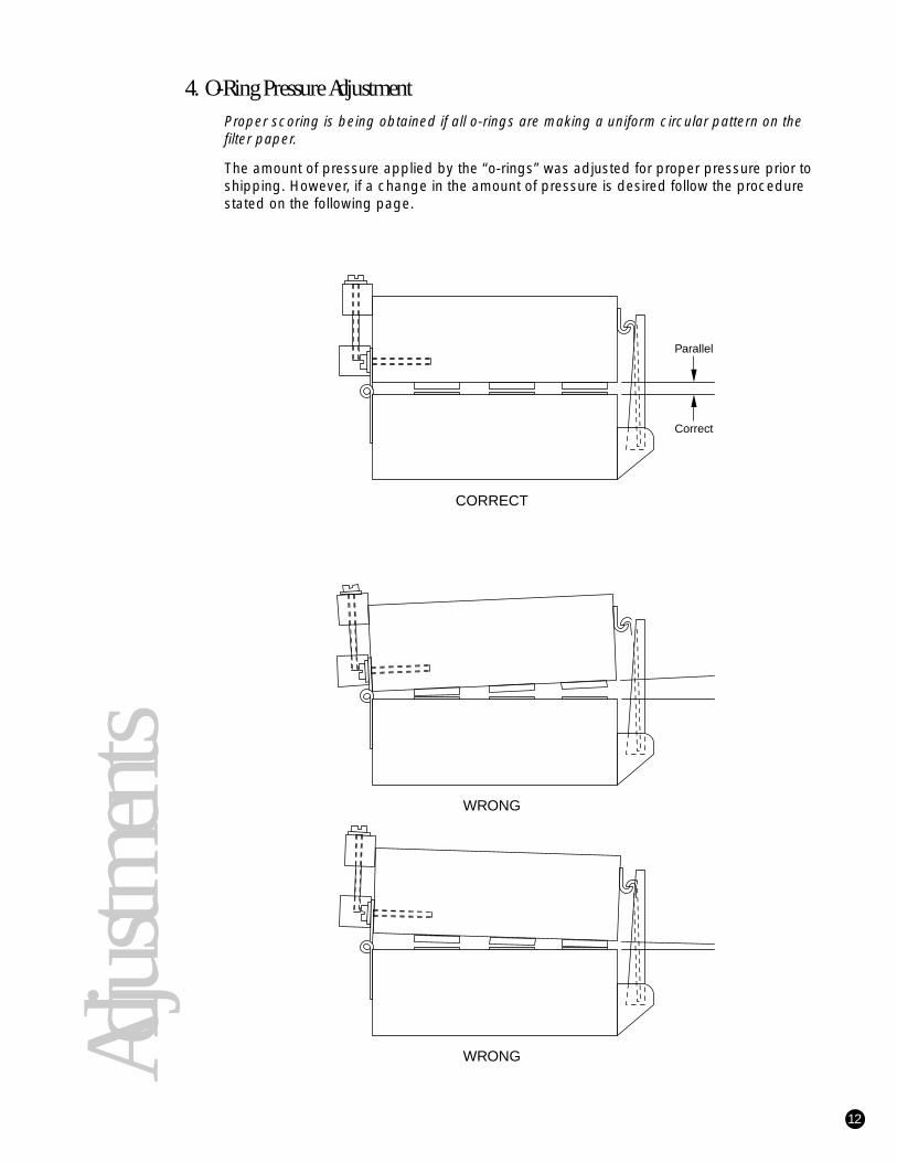
4. O-Ring Pressure AdjustmentProper scoring is being obtained if all o-rings are making a uniform circular pattern on thefilter paper.
The amount of pressure applied by the “o-rings” was adjusted for proper pressure prior toshipping. However, if a change in the amount of pressure is desired follow the procedurestated on the following page.
12
Adju
stmen
ts
WRONG
Parallel
Correct
CORRECT
WRONG

5. Adjusting Pressure on the Front Half of the Filter BlockAdjust the three (or four) latches on the front of the filter block. Turning the latches clock-wise will increase the amount of pressure applied by the front half of the filter block.Turning the latches counter-clockwise will decrease the amount of pressure.
Warning: Only turn the latches one full rotation at a time before re-testing the pressurebeing applied to the front half of the filter block.
6. Adjusting Pressure on the Back Half of the Filter BlockRelease the three (or four) latches on the front of the filter block and loosen the six “topscrews” on the top half of the filter block hinge.
Turning the “adjustment screws” clockwise will increase the amount of pressure beingapplied by the back half of the filter block. Turning the “adjustment screws” counter-clock-wise will decrease the amount of pressure being applied by the back half of the filterblock.
Warning: Only turn each “adjustment screw” 1/2 rotation before re-testing the pressurebeing applied to the back half of the filter block.
Prior to re-testing the back pressure of the filter block make certain the six “top screws”have been re-tightened.
13
Adju
stmen
ts
Adjustment Screws
Hinge Adjustment Blocks
Top Screws
Hinge
SIDE VIEW OF FILTER BLOCK
Latches
Front

7. AspirationCaution: Release the three (or four) latches on the block when the Harvester is not in useto prevent any “flattening” of the o-rings.
Release the latches on the filter block and raise the top half of the filter block. Place onestrip of filter paper over the metal screens on the bottom half of the filter block. The filterpaper should be wet to prevent leakage around the edges. Close the filter block, makingcertain all o-rings are completely inside the strip of filter paper. Fasten the latches to thestrikes on the top half of the filter block. Turn on the vacuum source, or open on-off vacu-um valve if vacuum source is already on. Check the vacuum gauge indication to makecertain a reading of 18” of Hg. or more is being obtained.
If the vacuum gauge does not read at least 18”of Hg. place the harvesting probe into micro-titre plates or test tubes (depending on type ofprobe being used) and repeatedly depresswash switch on probe until a reading of 18” ofHg. is obtained.
If a reading of 18” of Hg. is still not obtainedmake certain that all o-rings are “scoring” thepaper sufficiently and that all tubes in thesystem are secured.
Please contact Brandel if these steps arenot sufficient to obtain proper vacuum, asthe problem may be an insufficient vacu-um source.
14
Adju
stmen
ts
0
5
10
30
25
2015
Hg
VACUUM GUAGE

Optional Components for Your Harvester
1. Remote Programmable ControllerFor detailed instructions on using the Remote Programmable Controller, (if ordered) pleaseconsult the Remote Programmable Controller Manual.
To connect the remote programmable controller to your Harvester, first plug the Harvesterswitch cable into the “Harvester Switch” jack on the back of the controller.
Next, plug the timer box into a standard wall outlet.
It is strongly recommended that the Harvester power cord be plugged into CH #2 and thewas pump be plugged into CH #1. Using these two outlets will enable the user to have themanual wash available at any time.
2. Large-Capacity Reservoir with Auto-DrainThere are three main components that make up the auto-drain system.
1.Large-Capacity Collection Reservoir2.Auto-Drain Controller3.Auto-Drain Pump
Notice that on all the tubes attached to the reservoir are labels specifying where each tubing connection should be made.
1.Connect the tubing labeled “Drain Reservoir” to the drain on the plexiglass reservoir.2.Connect the tubing labeled “Connect to Drain Pump” the the auto-drain pump on the
horizontal fitting.3.Connect the tubing labeled “Connect to Collection Reservoir” coming from the fitting on
the auto-drain box to the top of he collection reservoir.4.Attach the tubing labeled “Connect to Vacuum Source” to a vacuum supply.5.The tubing attached to the drain pump that has no label goes to your final drain
receptacle.
Three electrical connections must also be made to the auto-drain box.
1.Connect the power cord to the auto-drain box2.Connect the collection reservoir sensor to the auto-drain box.3.Connect the auto-drain pump to the auto-drain controller
The included keys are to be used to switch the auto-drain box to either automatic or manu-al mode. In manual mode, the the collection reservoir can only be drained by depressingthe black button. When the collection reservoir is filled to the upper sensor, a red, flashinglight is activated and an audible alarm is sounded (if selected). In automatic mode, thecollection reservoir empties when filled to the top of the sensor. When harvesting in thismode, it is critical that the drain tubing from the pump is placed in an emptying receptacle.
In either mode, the collection reservoir will empty only to the point of the bottom of the sen-sor. If more drainage is required, depress and continually hold the black manual drain but-ton. Care must be taken so as not to completely empty the bottle and the pump as this willnecessitate a repriming of the pump.
15
Optio
ns

3. Hot-Cold Collection ValveThe hot-cold wash valve is designed to provide the ability for separate collection ofradioactive and non-radioactive waste.
If the hot-cold wash valve was not originally ordered with the Harvester and installed byBrandel, use the two extra holes located on the left side of the base plate of the Harvesterfor mounting the hot-cold wash valve.
When using the hot-cold wash valve connect the vinyl tubes on the collection reservoirbottles (labeled “connect to valve”) to the two remaining connectors on the bottom half ofthe hot-cold wash valve. Connect the tube on the plastic “Y” (labeled “connect to vacuumsource”) to your vacuum source. Connect the two remaining tubes on the plastic “Y”(labeled “connect to trap bottles”) to the collection bottles.
When using and disposing of non-radioactive waste turn the top half of the valve (usingthe handle installed in the valve) in the direction of “cold” port. Turning the valve clockwise(as far as possible) will allow for the use and disposal of radioactive waste into the “hot”collection reservoir bottle.
To disassemble the hot-cold wash valve remove the two screws located on the bottomside of the base plate which are securing the valve. Remove the four caphead screws onthe top half of the valve cover, counter-clockwise, thus removing the white colored valvehousing on the top of the valve. Remove the large cap screw inside the top half of thevalve such that both pieces will come apart. Use your fingers to remove the o-rings. Donot use a sharp instrument to remove the o-rings.
To assemble, reverse the above process. When tightening the cap screw make certainthat the o-rings are sealing against the bottom of the top half of the valve. Check the turn-ing motion for ease of movement.
16
Optio
ns
COLD
HOT
HOT
COLD
Harvester
Hot/ColdValve
'Y' Connector
CollectionBottles
Vacuum Source
On/OffValve
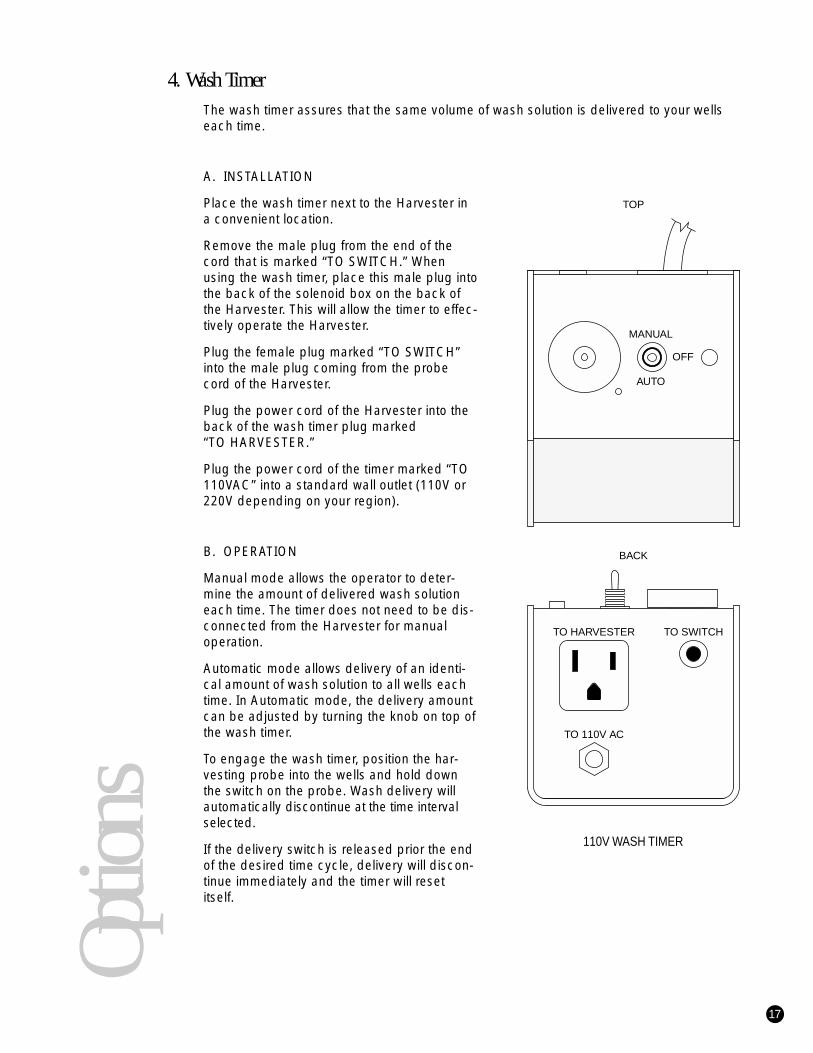
4. Wash TimerThe wash timer assures that the same volume of wash solution is delivered to your wellseach time.
A. INSTALLATION
Place the wash timer next to the Harvester ina convenient location.
Remove the male plug from the end of thecord that is marked “TO SWITCH.” Whenusing the wash timer, place this male plug intothe back of the solenoid box on the back ofthe Harvester. This will allow the timer to effec-tively operate the Harvester.
Plug the female plug marked “TO SWITCH”into the male plug coming from the probecord of the Harvester.
Plug the power cord of the Harvester into theback of the wash timer plug marked “TO HARVESTER.”
Plug the power cord of the timer marked “TO110VAC” into a standard wall outlet (110V or220V depending on your region).
B. OPERATION
Manual mode allows the operator to deter-mine the amount of delivered wash solutioneach time. The timer does not need to be dis-connected from the Harvester for manualoperation.
Automatic mode allows delivery of an identi-cal amount of wash solution to all wells eachtime. In Automatic mode, the delivery amountcan be adjusted by turning the knob on top ofthe wash timer.
To engage the wash timer, position the har-vesting probe into the wells and hold downthe switch on the probe. Wash delivery willautomatically discontinue at the time intervalselected.
If the delivery switch is released prior the endof the desired time cycle, delivery will discon-tinue immediately and the timer will resetitself.
17
Optio
ns
TO 110V AC
TO HARVESTER TO SWITCH
MANUAL
AUTO
OFF
TOP
BACK
110V WASH TIMER
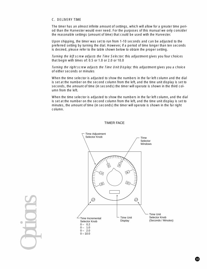
C. DELIVERY TIME
The timer has an almost infinite amount of settings, which will allow for a greater time peri-od than the Harvester would ever need. For the purposes of this manual we only considerthe reasonable settings (amount of time) that could be used with the Harvester.
Upon shipping, the timer was set to run from 1-10 seconds and can be adjusted to thepreferred setting by turning the dial. However, if a period of time longer than ten secondsis desired, please refer to the table shown below to obtain the proper setting.
Turning the left screw adjusts the Time Selector: this adjustment gives you four choicesthat begin with times of: 0.5 or 1.0 or 2.0 or 10.0
Turning the right screw adjusts the Time Unit Display: this adjustment gives you a choiceof either seconds or minutes
When the time selector is adjusted to show the numbers in the far left column and the dialis set at the number on the second column from the left, and the time unit display is set toseconds, the amount of time (in seconds) the timer will operate is shown in the third col-umn from the left.
When the time selector is adjusted to show the numbers in the far left column, and the dialis set at the number on the second column from the left, and the time unit display is set tominutes, the amount of time (in seconds) the timer will operate is shown in the far right column.
18
Optio
ns
01
2 3
45
Time IncrementalSelector Knob0 – 0.20 – 1.00 – 2.00 – 10.0
Time Adjustment Selector Knob
Time Unit Display
TImeSelector Windows
Time Unit Selector Knob(Seconds / Minutes)
TIMER FACE

5. Multi-Wash Systems(for additional washes)
A complete wash system (if ordered) consists of:1 each Wash Pump (optional)1 each Wash Media Bottle1 each Multi-Wash Table with Switch1 each Wash Trough (mounted onto multi-wash table)1 each Solenoid (mounted onto multi-wash table)1 each 2-Way Flow Regulator Valve 1 each Necessary Tubing
Only part of the system may have been ordered with your Harvester. All instructions shouldbe modified accordingly.
A. CONNECTIONS AND INSTALLATION
1.Connect the tubing from the multi-wash buffer bottle, labeled “connect to multi-wash pump,” to the wash pump.
2.Connect the tubing labeled “connect to multi-wash solenoid” to the white fitting of the solenoid on the multi-wash table.
3.Prime the multi-wash pump in the same manner as priming the wash pump for the harvester(see page 3).
4.Place the multi-wash table near the Harvester in such a manner that the wash trough is close to the front edge of the Harvester.
5.The flow regulator valve has already been pre-set. If a change in flow is desired turn the handle on the flow regulator valve. (Turning the handle parallel to the valve increases the flow, turning the handle perpendicular decreases the flow).
6.Plug the multi-wash pump plug into the back of the multi-wash solenoid.7.Plug the multi-wash switch (located on the multi-wash table) into the back of the
multi-wash solenoid.8.Plug the multi-wash solenoid into a standard wall outlet (110V or 220V depending on
your region).
The wash is fed into the trough by the depression of its corresponding switch located onthe multi-wash table. (If a wash pump was purchased with the multi-wash system, the two-way valve on the tubing from the wash pump can be adjusted to regulate the rate of flowinto the wash trough). With vacuum pressure applied and after filling the wash trough,place the harvesting probe into the wash trough. The harvesting probe will aspirate theadditional wash fluid from the trough onto the filter paper. Additional washings may beaccomplished by repeating this procedure.
19
Optio
ns

Tubing for 12-Sample Harvesters
1. Modification for Interchangeable Harvesting ProbeAll BRANDEL Harvesters are pre-equipped for interchangeable harvesting probes.
2. Mounting Interchangeable Harvesting ProbesThe receptacle for the interchangeable harvesting probe is mounted onto the three holes on the leftside of the top filter block. The receptacle plug (one receptacle is included for each probe) for theinterchangeable harvesting probe is mounted on top of the receptacle. Mount the receptacle suchthat the tubing clip is facing towards the inside of the Harvester. Push down gently on the receptaclewith a rocking motion until the receptacle is resting on top of the red rubber gasket. Do not bend anyof the needles in the plug. Place wing nuts onto the four threaded posts and tighten until they juststart applying pressure to the red gasket. Tighten wing nuts alternately, one turn at a time, until moderate pressure is applied to ensure no vacuum leakage.
Caution: Do not tighten wing nuts excessivelysuch that needles in the receptacle mountand needles in the receptacle plug touch.
A new wash manifold must also be substituted when changing harvestingprobes. Remove the four wing nuts. Makecertain the “o-ring” is still in place and notresting on top of the four metal nuts. Placethe second wash manifold on (make certain“o-ring” is outside all needles of wash mani-fold) and gently tighten the wing nuts untilthey just start applying pressure on the “o-ring”. Next, tighten the wing nuts, alternately,one turn at a time, until moderate pressure isapplied to the “o-ring”.
Caution: Do not tighten wing nuts excessively.
20
Tubin
g
Top Receptacle
Bottom Receptacle
Rubber Gasket
Plug Mount

3. Tubing Diagram for the 12-Sample HarvesterRefer to the diagram below for tubing information.
The tubing from the top of the filter block should run to the receptacle mount and correspond witheach number, (i.e., # 1 on the filter block to # 1 on the receptacle, #2 to #2, etc.). Tubing from thereceptacle plug should then correspond with the harvesting probe in the same manner.
21
Tubin
g
12
34
56
78
910
1112
XX 2 7 12
XX 1 6 11
XX
5 10
XX X 4
9
XX X 3
8
1 2 3 4 5 6 7 8 9 10 11 12

General MaintenanceYour Brandel Harvester has been designed for relatively maintenance free service.However, certain steps should be taken to provide optimal service from your Harvester.The steps detailed below will not only keep your Harvester aesthetically clean, but alsoprovide for uniform delivery and aspiration – even after years of use.
After shipment, and/or continued use of the Harvester the white plastic permanent tiesbinding together the clear plastic tubing may need to be tightened. However, cautionshould be exercised so as not to pinch shut any tubes. Normally, pushing down on thesquare part (head) of the plastic permanent tie for one or two notches is sufficient tosecure the tubes into a firmly held bundle.
All outside lucite parts can be cleaned with alcohol, Windex or any other cleaning agent ofyour choice which is not abrasive or a solvent to lucite.
After a few hours of occasional use or continued use over the course of a day the tubingshould be rinsed out with deionized water or a solution of 30% alcohol. After a period oftime a chemical solution can also be used to prevent or eliminate any counts from remain-ing inside the tubing.
A soft bristled brush (such as a toothbrush) may be used with water or alcohol to clean thestainless steel filter screens.
After prolonged use over years you may wish Brandel to provide replacement tubing, o-rings or screens.
Brandel can provide tubing in coils (you re-tube the lines to be changed) or all tubes com-ing to and going from harvesting probe pre-cut with a new wash manifold (for your conve-nience), labeled and ready to be installed. This tubing can also be pre-cut for your collec-tion manifold (new collection manifold, for your convenience), labeled and ready to beinstalled.
All o-rings are supplied with epoxy for replacement.
Your Harvester’s stainless steel filter screens have been pressed into your filter block.Brandel will supply the replacement screens for you to fit back into place. Simply removethe old screen; pry out with a suitable object, and place the new screens into place.
Main
tenan
ce
22

Tips for Using Your Harvester
1. Proper AspirationMake certain that the aspiration needles in the harvesting probe are not sitting on the bot-tom of the wells when aspirating. Hold the probe slightly above the bottom of the wells inorder to prevent the bottom of the aspiration needles from sealing against the bottom ofthe wells. If the aspiration needles of the harvesting probe are sealing against the bottomof the wells, certain wells may overflow.
Make certain that with a strip of filter paper inside the filtering block your vacuum gauge isreading a minimum of 18” Hg. while aspirating. A vacuum reading of less than 18” Hg.may lead to poor aspiration, and individual wells overflowing.
While not using the Harvester, the filter block should be closed but not latched, to prevent unnecessary strain on the o-rings.
Make certain that if you are using a microtitre plate configuration you have adjusted thetwo way valve on the black wash pump to prevent an excessive amount of delivery intoeach individual well.
Make certain that the handle on the on-off vacuum valve is fully turned to the “HARVEST”position in order to ensure proper aspiration from the harvesting probe.
If you are using the tray on the front of the Harvester, and are harvesting (especially fromtest tubes), make certain that while the harvesting probe is held off the bottom of the wellsthat the tubing is not being crimped on the back side of the harvesting probe. Holding theprobe near the latches on the filter block (in other words, at the back edge of the tray) andvery high off the bottom of the wells (5” or more) may cause a decrease in the aspiration.
2. Proper DeliveryMake certain that the handle on the on-off vacuum valve is fully turned to the “HARVEST”position and secured in place to allow for delivery to the harvesting probe. If the handle isnot fully turned to the “HARVEST” position, the buffer solution will go directly into your col-lection flask.
Make certain that the wash pump has been completely primed.
Make certain that if you are using a two-way valve on the black wash pump not to have thevalve closed so far as to prevent an adequate amount of delivery into each individual well.
3. After HarvestingPrior to placing the two metal rods of the harvesting probe into the corresponding holes onthe top half of the filter block, pull back on the tygon tubing which is above the filter block.Pulling this tubing toward the back of the Harvester will allow the harvesting probe rests(two metal rods) to fit better and remain seated into the filter block.
23

Filter Paper for All Harvesters
BRANDEL, Inc.8561 Atlas DriveGaithersburg, MD 20850Telephone: 301-948-6506Fax: 301-869-5570E-mail: [email protected]://www.brandel.com
24
Filter
Pap
er
* Please enter the letter that corresponds to your counter or direct reader: B Beckman L LKB P PackardOthers filters available on request
Harvester Reeves Angel 934H Whatman GF/B Whatman GF/C
For Standard Format Harvesters without Deposit/Dispensing Systems12-sample Harvesters FP-12 FP-101 FP-20124-sample Harvesters FP-24 FP-100 FP-20030-sample Harvesters FP-30 FP-130 FP-23036-sample Harvesters FP-36 FP-136 FP-23648-sample Harvesters FP-48 FP-105 FP-20596-sample Harvesters FPD-96 FPD-196 FPD-296
For Standard Format Harvesters with Deposit/Dispensing Systems12-sample Harvesters FPD-12 FPD-101 FPD-20124-sample Harvesters FPD-24 FPD-100 FPD-20030-sample Harvesters FPD-30 FPD-130 FPD-23036-sample Harvesters FPD-36 FPD-136 FPD-23648-sample Harvesters FPD-48 FPD-105 FPD-20596-sample Harvesters FPD-96 FPD-19 FPD-296
For All Counter-Compatible Harvesters12-sample, 20ml vials FP*-12 FP*-112 FP*-21218-sample, 5 or 7ml vials FP*-18 FP*-118 FP*-21824-sample, 20ml vials FP*-24 FP*-124 FP*-22430-sample, 20ml vials FP*-30 FP*-130 FP*-23036-sample, 5 or 7ml vials FP*-36 FP*-136 FP*-23636-sample, 20ml vials FP*-36L FP*-136L FP*-23648-sample, 5 or 7ml vials FP*-48 FP*-148 FP*-24848-sample, 20ml vials FP*-48L FP*-148L FP*-248L96-sample, 5 or 7ml vials FP*-96 FP*-196 FP*-29696-sample, 20ml vials FP*-96L FP*-196L FP*-296L
For All Direct Radioactive Reader Compatibles24-sample 4x6 format FP*R-24 FP*R-124 FP*R-22448-sample 4x12 format FP*R-05 FP*R-105 FP*R-20596-sample 6x16 format FP*R-96 FP*R-196 FP*R-29696-sample microtitre FPX*R-96 FPX*R-196 FPX*R-29

WarrantyBiomedical Research and Development Laboratory, Inc. (BRANDEL) guarantees for aperiod of one year from the original date of shipment, all parts manufactured by it to befree from defects in workmanship and materials. All defective parts will be replaced with-out charge for parts or labor. BRANDEL will not accept expense or labor incident to thereplacement of any part outside of its factory.
WarningThe purchaser assumes all risks in the use and handling of items sold by BRANDEL.BRANDEL is not liable for loss or damage resulting from use or misuse of the productssold by BRANDEL.
25