
Harvard Peristaltic Pump Series User’s Guide Manuals/Harvard... · Harvard Peristaltic Pump...
94
Publication 5423-001- Rev D Harvard Peristaltic Series MA1 70-7xxx Harvard Peristaltic Pump Series User’s Guide PATENTS PENDING
Transcript of Harvard Peristaltic Pump Series User’s Guide Manuals/Harvard... · Harvard Peristaltic Pump...

Publication 5423-001- Rev D
Harvard Peristaltic Series MA1 70-7xxx
Harvard Peristaltic
Pump Series
User’s Guide
PATENTS PENDING
Table of Contents 2
Publication 5423-001-Rev-D Harvard Peristaltic Pump Series User’s Manual
Quick Guide ......................................................................................................................... 5
10 Things You Need To Know ..................................................................................... 5
General Information .......................................................................................................... 6
Conventions Used In This Guide ................................................................................. 6
Warranty and Repair Information ................................................................................. 7
Manual Description ................................................................................................... 7
Warranty ..................................................................................................................... 7
Repair Facilities and Parts ......................................................................................... 7
Serial Numbers ........................................................................................................... 7
Calibrations ................................................................................................................ 7
Safety Information ......................................................................................................... 8
Introduction To The Harvard Peristaltic Pump ........................................................... 9
Product Overview – Theory of Operation ................................................................... 9
Pump Models ................................................................................................................. 9
Specifications ............................................................................................................... 10
Setting Up The Harvard Peristaltic With EZ PRO™..................................................... 12
Physical Views ............................................................................................................. 12
Power Connections and Pump Startup ...................................................................... 13
Navigating The Harvard Peristaltic EZ PRO™ Software .............................................. 14
The Harvard Peristaltic Workspace ........................................................................ 14
Selecting An Item From A Menu List .................................................................. 15
Information/Warning messages .......................................................................... 16
EZ PRO™ Touch Screen Button Reference ............................................................. 17
System Setting Adjustments ........................................................................................ 18
Setting the Audible Alarms ...................................................................................... 18
Locking The Touch Screen .................................................................................... 20
Setting the Time and Date ...................................................................................... 21
Change Logo ............................................................................................................ 21
Setting Backlight Level ............................................................................................ 22
Setting Pump Address Value ................................................................................... 22
Pump Information ................................................................................................... 23
Power Up Running .................................................................................................. 23
Tubing Loading ........................................................................................................... 24
SUBJECT PAGE NO.
Table of Contents

3
Publication 5423-001-Rev-D Harvard Peristaltic Pump Series User’s Manual
Using The Harvard Peristaltic ........................................................................................ 25
Pump Operation Overview ......................................................................................... 25
Overview of Methods .................................................................................................. 25
Method Types .............................................................................................................. 25
EZ PRO™ Quick Start Methods ................................................................................ 25
EZ PRO™ Preloaded Methods .................................................................................. 25
EZ PRO™ User-Defined Methods ............................................................................. 25
Running The Pump ..................................................................................................... 26
Controlling The Pump ............................................................................................ 26
Basic Method Operations ........................................................................................ 26
Viewing Current Method Parameters .................................................................. 26
Tube Selection ..................................................................................................... 27
Combined Flow Operation .................................................................................. 28
Tube Run-in ......................................................................................................... 30
Tube Calibration .................................................................................................. 30
Controlling The Pump Using A Stored Method ................................................. 31
Using an EZ PRO™ Quick Start Method ...................................................................... 34
Basic Operation ....................................................................................................... 34
Quick Start Method Variables ................................................................................. 35
Rate Select ............................................................................................................ 35
Target Volume/Time Select ................................................................................ 36
Using an EZ PRO™ Preloaded/User-Defined Method ................................................ 37
Preloaded/User-Defined Method Workflow ......................................................... 38
Setting A Time Delay For Method Operation ........................................................ 39
Creating an EZ PRO™ New Method ............................................................................ 40
Modifying a Preloaded/User-Defined Method ....................................................... 42
Changing the Order of Steps in a Method ......................................................... 42
Deleting a Step From a Method .......................................................................... 42
Duplicating a Step In a Method .......................................................................... 43
Defining Method Step Parameters .............................................................................. 43
Pump Operation Profiles ......................................................................................... 44
Constant Rate Profile ........................................................................................... 45
Ramp Profile ......................................................................................................... 46
Stepped Profile ..................................................................................................... 48
Pulse Profile ......................................................................................................... 50
Concentration Profile ........................................................................................... 52
Incorporating Advanced Options (Commands and I/O) Into A Method ............. 55
Go To Step ........................................................................................................... 55
Delay .................................................................................................................... 56
Repeat Step .......................................................................................................... 57
Table of Contents

4
Publication 5423-001-Rev-D Harvard Peristaltic Pump Series User’s Manual
Link Method ......................................................................................................... 58
Stop ....................................................................................................................... 58
I/O Event Triggers ............................................................................................... 59
I/O Trigger (out) .................................................................................................. 59
I/O Event (in) ....................................................................................................... 61
I/O Event Link (in) .............................................................................................. 62
Managing EZ PRO™ Methods ...................................................................................... 63
Saving A Copy Of A Method .................................................................................. 63
Renaming A Method ............................................................................................... 63
Appending A Method .............................................................................................. 64
Deleting A Method .................................................................................................. 64
Method Export and Import ..................................................................................... 65
External Pump Control ................................................................................................ 66
Pump Chain Commands ............................................................................................. 67
Using the Harvard Peristaltic Pump Chain Commands ......................................... 67
Error Messages ......................................................................................................... 68
System Commands .................................................................................................. 69
Run Commands ....................................................................................................... 73
Rate Commands ....................................................................................................... 73
Volume Commands ................................................................................................. 76
Time Commands ...................................................................................................... 77
Digital I/O Commands ............................................................................................ 78
Internal Commands ................................................................................................. 79
Appendices ........................................................................................................................ 80
Appendix A: Tubing Tables ....................................................................................... 80
Appendix B: External connections ............................................................................. 83
User I/O Connector Specifications ......................................................................... 83
Analog Input ............................................................................................................ 84
USB .......................................................................................................................... 85
RS-485 ....................................................................................................................... 87
Setting the Address on the Control Box / Master Unit ........................................ ..88
Appendix C: Maintenance .......................................................................................... 89
Maintenance ............................................................................................................. 89
Battery Replacement ................................................................................................ 89
Troubleshooting ....................................................................................................... 90
Upgrading EZ PRO™ Software ................................................................................ 91
Harvard Peristaltic Display Error Messages ............................................................ 92
Appendix D: Ordering Information ............................................................................ 93
Table of Contents
5
Publication 5423-001-Rev-D Harvard Peristaltic Pump Series User’s Manual
Quick Guide
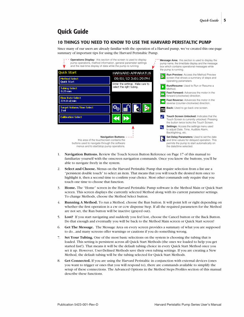
10 THINGS YOU NEED TO KNOW TO USE THE HARVARD PERISTALTIC PUMPSince many of our users are already familiar with the operation of a Harvard pump, we’ve created this one-page summary of important tips for using the Harvard Peristaltic Pump.
1. Navigation Buttons. Review the Touch Screen Button Reference on Page 17 of this manual to familiarize yourself with the onscreen navigation commands. Once you know the buttons, you’ll be able to navigate freely in the system.
2. Select and Choose. Menus on the Harvard Peristaltic Pump that require selection from a list use a “persistent double touch” to select an item. That means that you will touch the desired item once to highlight it, then a second time to confirm your choice. Most other commands only require that you touch one time to choose that function.
3. Home. The “Home” screen in the Harvard Peristaltic Pump software is the Method Main or Quick Start screen. This screen displays the currently selected Method along with its current parameter settings. To change Methods, choose the Method Select button.
4. Running A Method. To run a Method, choose the Run button. It will point left or right depending on whether the first operation is a cw or ccw dispense Step. If all the required parameters for the Method are not set, the Run button will be inactive (grayed out).
5. Lost? If you start navigating and suddenly you feel lost, choose the Cancel button or the Back Button. Do that enough and eventually you will be back to the Method Main screen or Quick Start screen!
6. Get The Message. The Message Area on every screen provides a summary of what you are supposed to do...and many screens offer warnings or cautions if you do something wrong.
7. Set Your Tubing. One of the most basic selections on the system is choosing the tubing that is loaded. This setting is persistent across all Quick Start Methods (the ones we loaded to help you get started fast!). That means it will be the default tubing choice in every Quick Start Method once you set it up. However, User-Defined Methods save their own tubing settings. If you are creating a New Method, the default tubing will be the tubing selected for Quick Start Methods.
8. Get Connected. If you are using the Harvard Peristaltic in conjunction with external devices (ones you want to trigger or ones that you will respond to), there are commands available to simplify the setup of these connections. The Advanced Options in the Method Steps Profiles section of this manual describe these functions.
Back: Used to go back one screen.
Run Preview: Access the Method Preview screen that shows a summary of steps and operating parameters.
Fast Forward: Advances the motor in the forward (clockwise) direction.
Fast Reverse: Advances the motor in the reverse (counter-clockwise) direction.
Settings: Access the settings menu used to adjust Date, Time, Audible Alarm, Backlighting, etc.
Set Delay Parameters: Used to set the date and time values for delayed operation. This permits the pump to start automatically on the date/time selected.
Run/Resume: Used to Run or Resume a Method.
Touch Screen Unlocked: Indicates that the Touch Screen is currently unlocked. Pressing the button twice locks the Touch Screen.
Navigation Buttons: this area of the touchscreen contains the
buttons used to navigate through the software menus and to start/stop pump operations.
Message Area: this section is used to display the pump name, the time/date display and the message box which contains operational messages while the pump is running.
Operations Display: this section of the screen is used to display pump operations, method information, general parameter settings and the real-time display of data while the pump is running.
Quick Guide
General Information
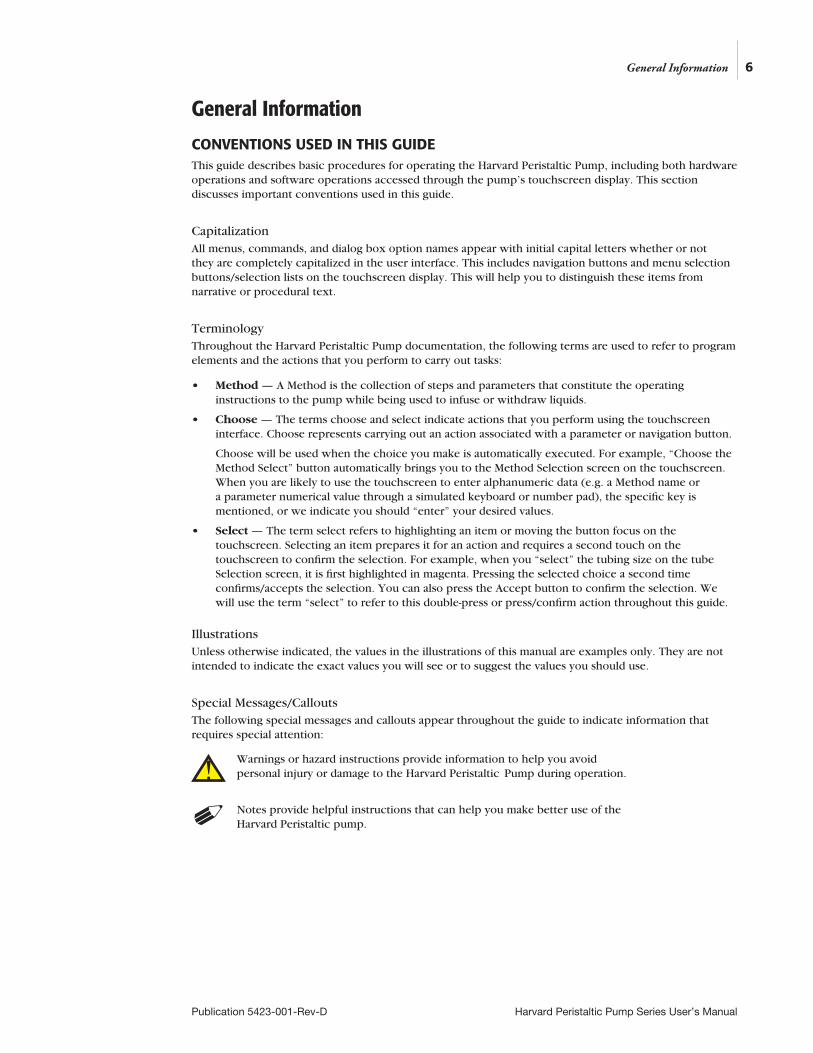
CONVENTIONS USED IN THIS GUIDEThis guide describes basic procedures for operating the Harvard Peristaltic Pump, including both hardware operations and software operations accessed through the pump’s touchscreen display. This section discusses important conventions used in this guide.
CapitalizationAll menus, commands, and dialog box option names appear with initial capital letters whether or not they are completely capitalized in the user interface. This includes navigation buttons and menu selection buttons/selection lists on the touchscreen display. This will help you to distinguish these items from narrative or procedural text.
TerminologyThroughout the Harvard Peristaltic Pump documentation, the following terms are used to refer to program elements and the actions that you perform to carry out tasks:
• Method — A Method is the collection of steps and parameters that constitute the operating instructions to the pump while being used to infuse or withdraw liquids.
• Choose — The terms choose and select indicate actions that you perform using the touchscreen interface. Choose represents carrying out an action associated with a parameter or navigation button.
Choose will be used when the choice you make is automatically executed. For example, “Choose the Method Select” button automatically brings you to the Method Selection screen on the touchscreen. When you are likely to use the touchscreen to enter alphanumeric data (e.g. a Method name or a parameter numerical value through a simulated keyboard or number pad), the specific key is mentioned, or we indicate you should “enter” your desired values.
• Select — The term select refers to highlighting an item or moving the button focus on the touchscreen. Selecting an item prepares it for an action and requires a second touch on the touchscreen to confirm the selection. For example, when you “select” the tubing size on the tube Selection screen, it is first highlighted in magenta. Pressing the selected choice a second time confirms/accepts the selection. You can also press the Accept button to confirm the selection. We will use the term “select” to refer to this double-press or press/confirm action throughout this guide.
IllustrationsUnless otherwise indicated, the values in the illustrations of this manual are examples only. They are not intended to indicate the exact values you will see or to suggest the values you should use.
Special Messages/CalloutsThe following special messages and callouts appear throughout the guide to indicate information that requires special attention:
Warnings or hazard instructions provide information to help you avoid personal injury or damage to the Harvard Peristaltic Pump during operation.
Notes provide helpful instructions that can help you make better use of the Harvard Peristaltic pump.
6
Publication 5423-001-Rev-D Harvard Peristaltic Pump Series User’s Manual
General Information
!
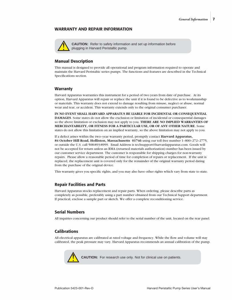
WARRANTY AND REPAIR INFORMATION
Manual DescriptionThis manual is designed to provide all operational and program information required to operate and maintain the Harvard Peristaltic series pumps. The functions and features are described in the Technical Specifications section.
WarrantyHarvard Apparatus warranties this instrument for a period of two years from date of purchase. At its option, Harvard Apparatus will repair or replace the unit if it is found to be defective as to workmanship or materials. This warranty does not extend to damage resulting from misuse, neglect or abuse, normal wear and tear, or accident. This warranty extends only to the original consumer purchaser.
IN NO EVENT SHALL HARVARD APPARATUS BE LIABLE FOR INCIDENTAL OR CONSEQUENTIAL DAMAGES. Some states do not allow the exclusion or limitation of incidental or consequential damages so the above limitation or exclusion may not apply to you. THERE ARE NO IMPLIED WARRANTIES OF MERCHANTABILITY, OR FITNESS FOR A PARTICULAR USE, OR OF ANY OTHER NATURE. Some states do not allow this limitation on an implied warranty, so the above limitation may not apply to you.
If a defect arises within the two–year warranty period, promptly contact Harvard Apparatus, 84 October Hill Road, Holliston, Massachusetts 01746 using our toll free number 1–800–272–2775, or outside the U.S. call 508-893-8999. Email Address is [email protected]. Goods will not be accepted for return unless an RMA (returned materials authorization) number has been issued by our customer service department. The customer is responsible for shipping charges for non-warranty repairs. Please allow a reasonable period of time for completion of repairs or replacement. If the unit is replaced, the replacement unit is covered only for the remainder of the original warranty period dating from the purchase of the original device.
This warranty gives you specific rights, and you may also have other rights which vary from state to state.
Repair Facilities and PartsHarvard Apparatus stocks replacement and repair parts. When ordering, please describe parts as completely as possible, preferably using a part number obtained from our Technical Support department. If practical, enclose a sample part or sketch. We offer a complete reconditioning service.
Serial NumbersAll inquiries concerning our product should refer to the serial number of the unit, located on the rear panel.
CalibrationsAll electrical apparatus are calibrated at rated voltage and frequency. While the flow and volume will stay calibrated, the peak pressure may vary. Harvard Apparatus recommends an annual calibration of the pump.
CAUTION: For research use only. Not for clinical use on patients.
CAUTION: Refer to safety information and set up information before plugging in Harvard Peristaltic pump.
7
Publication 5423-001-Rev-D Harvard Peristaltic Pump Series User’s Manual
General Information
!
!
SAFETY INFORMATION
Please read the following safety precautions to ensure proper use of your pump. If the equipment is used in a manner not specified, the protection provided by the equipment may be impaired.
To Prevent Hazard or Injury:
Use Proper Power SupplyThe pump is supplied with an approved power supply and line cord. To maintain the safety integrity of the device, use only the following power supplies:
Globtek Inc. Model: GTM-21097-5048-18 Output: 30 VAC, 1.67 A Input: 100-240V~50-60 Hz 1.6 A
Use Proper Line CordUse only the specified line cord for this product and make sure line cord is certified for country of use. The operating voltage for the Harvard Peristaltic Series is 30 VDC. The universal power supply operating voltage range is 100-240 VAC, 50-60 Hz.
Make Proper ConnectionsMake sure all connections are made properly and securely. Any signal wire connections to the unit must be no longer than 3 meters (except RS485 pump-to-pump communication cable).
Observe All Terminal RatingsReview the operating manual to learn the ratings on all connections.
Avoid Exposed CircuitryDo not touch any electronic circuitry inside of the product.
Avoid Pinch HazardA pinch hazard may exist between the rollers. Avoid placing fingers between these points while the pump is running.
Do Not Operate with Suspected FailuresIf damage is suspected on or to the product do not operate the product. Contact qualified service personnel to perform inspection.
Orient the Equipment ProperlyDo not orient the equipment so that it is difficult to manage the connection and disconnection of devices.
Place Product in Proper EnvironmentReview the operating manual for guidelines for proper operating environments.
Observe all Warning Labels on ProductRead all labels on product to ensure proper usage.
Protective Ground Terminal
CAUTION Refer to Manual
8
Publication 5423-001-Rev-D Harvard Peristaltic Pump Series User’s Manual
General Information
!
9
Publication 5423-001-Rev-D Harvard Peristaltic Pump Series User’s Manual
Introduction To The Harvard Peristaltic Pump
PRODUCT OVERVIEW – THEORY OF OPERATIONThe Harvard Peristaltic Pump series is a family of high-accuracy peristaltic pumps designed for applications including large volume infusion, sample preparation, recirculating baths, organ/tissue perfusion, dosing/filling, dispensing cell culture media and large volume dispensing. The Harvard Peristaltic Pump incorporates a microprocessor controlled, small step angle stepping motor. Advanced micro-stepping techniques are employed to further reduce the step angle to eliminate flow pulsation. The pump is engineered to provide flow accuracy within 1%.
The Harvard Peristaltic Pump uses a touchscreen interface and advanced software to control operation. External I/O interfaces permit external control via an independent computer or device. The application software provides convenient selection of common tube sizes from a Lookup Table, as well as insertion of custom tube sizes. The system is then able to calculate the cross-sectional area of the tube selected and calibrate the flow rate and volume accumulation, displaying real-time operating characteristics via on-screen graphics.
PUMP MODELSThe Harvard Peristaltic Pump is available with three pump heads designed for different operating environments and varying degrees of operational flexibility. All configurations support dispensing in either direction (clockwise or counter-clockwise). All can support simplified “Quick-start” pumping or advanced pumping profiles and I/O interactions, “Methods”.
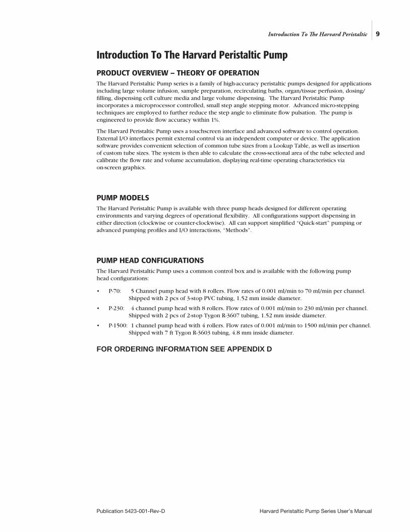
PUMP HEAD CONFIGURATIONSThe Harvard Peristaltic Pump uses a common control box and is available with the following pump head configurations:
• P-70: 5 Channel pump head with 8 rollers. Flow rates of 0.001 ml/min to 70 ml/min per channel. Shipped with 2 pcs of 3-stop PVC tubing, 1.52 mm inside diameter.
• P-230: 4 channel pump head with 8 rollers. Flow rates of 0.001 ml/min to 230 ml/min per channel. Shipped with 2 pcs of 2-stop Tygon R-3607 tubing, 1.52 mm inside diameter.
• P-1500: 1 channel pump head with 4 rollers. Flow rates of 0.001 ml/min to 1500 ml/min per channel. Shipped with 7 ft Tygon R-3603 tubing, 4.8 mm inside diameter.
FOR ORDERING INFORMATION SEE APPENDIX D
Introduction To The Harvard Peristaltic
10
Publication 5423-001-Rev-D Harvard Peristaltic Pump Series User’s Manual
Introduction To The Harvard Peristaltic
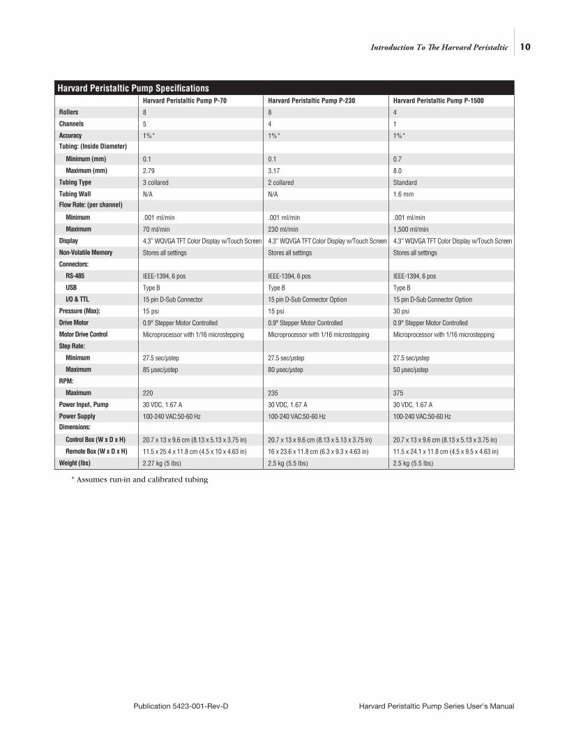
Harvard Peristaltic Pump SpecificationsHarvard Peristaltic Pump P-70 Harvard Peristaltic Pump P-230 Harvard Peristaltic Pump P-1500
Rollers 8 8 4
Channels 5 4 1
Accuracy 1%* 1%* 1%*
Tubing: (Inside Diameter)
Minimum (mm) 0.1 0.1 0.7
Maximum (mm) 2.79 3.17 8.0
Tubing Type 3 collared 2 collared Standard
Tubing Wall N/A N/A 1.6 mm
Flow Rate: (per channel)
Minimum .001 ml/min .001 ml/min .001 ml/min
Maximum 70 ml/min 230 ml/min 1,500 ml/min
Display 4.3” WQVGA TFT Color Display w/Touch Screen 4.3” WQVGA TFT Color Display w/Touch Screen 4.3” WQVGA TFT Color Display w/Touch Screen
Non-Volatile Memory Stores all settings Stores all settings Stores all settings
Connectors:
RS-485 IEEE-1394, 6 pos IEEE-1394, 6 pos IEEE-1394, 6 pos
USB Type B Type B Type B
I/O & TTL 15 pin D-Sub Connector 15 pin D-Sub Connector Option 15 pin D-Sub Connector Option
Pressure (Max): 15 psi 15 psi 30 psi
Drive Motor 0.9° Stepper Motor Controlled 0.9° Stepper Motor Controlled 0.9° Stepper Motor Controlled
Motor Drive Control Microprocessor with 1/16 microstepping Microprocessor with 1/16 microstepping Microprocessor with 1/16 microstepping
Step Rate:
Minimum 27.5 sec/µstep 27.5 sec/µstep 27.5 sec/µstep
Maximum 85 µsec/µstep 80 µsec/µstep 50 µsec/µstep
RPM:
Maximum 220 235 375
Power Input, Pump 30 VDC, 1.67 A 30 VDC, 1.67 A 30 VDC, 1.67 A
Power Supply 100-240 VAC:50-60 Hz 100-240 VAC:50-60 Hz 100-240 VAC:50-60 Hz
Dimensions:
Control Box (W x D x H) 20.7 x 13 x 9.6 cm (8.13 x 5.13 x 3.75 in) 20.7 x 13 x 9.6 cm (8.13 x 5.13 x 3.75 in) 20.7 x 13 x 9.6 cm (8.13 x 5.13 x 3.75 in)
Remote Box (W x D x H) 11.5 x 25.4 x 11.8 cm (4.5 x 10 x 4.63 in) 16 x 23.6 x 11.8 cm (6.3 x 9.3 x 4.63 in) 11.5 x 24.1 x 11.8 cm (4.5 x 9.5 x 4.63 in)
Weight (lbs) 2.27 kg (5 lbs) 2.5 kg (5.5 lbs) 2.5 kg (5.5 lbs)
* Assumes run-in and calibrated tubing
11
Publication 5423-001-Rev-D Harvard Peristaltic Pump Series User’s Manual
Introduction To The Harvard Peristaltic
Harvard Peristaltic Specifications (continued)
Harvard Peristaltic Pump P-70 Harvard Peristaltic Pump P-230 Harvard Peristaltic Pump P-1500
Atmospheric Specifications:
Operating Temperature 4°C to 40°C (40°F to 104°F)* 4°C to 40°C (40°F to 104°F) 4°C to 40°C (40°F to 104°F)
Storage Temperature -10°C to 70°C (14°F to 158°F) -10°C to 70°C (14°F to 158°F) -10°C to 70°C (14°F to 158°F)
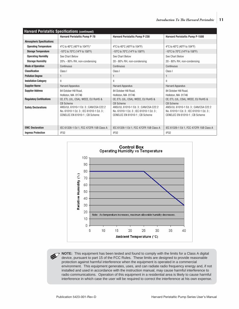
Operating Humidity See Chart Below See Chart Below See Chart Below
Storage Humidity 20% - 80% RH, non-condensing 20 - 80% RH, non-condensing 20 - 80% RH, non-condensing
Mode of Operation Continuous Continuous Continuous
Classification Class I Class I Class I
Pollution Degree 1 1 1
Installation Category II II II
Supplier Name Harvard Apparatus Harvard Apparatus Harvard Apparatus
Supplier Address 84 October Hill Road, Holliston, MA 01746
84 October Hill Road, Holliston, MA 01746
84 October Hill Road, Holliston, MA 01746
Regulatory Certifications CE, ETL (UL, CSA), WEEE, EU RoHS & CB Scheme
CE, ETL (UL, CSA), WEEE, EU RoHS & CB Scheme
CE, ETL (UL, CSA), WEEE, EU RoHS & CB Scheme
Safety Declarations ANSI/UL 61010-1 Ed. 3 ; CAN/CSA C22.2 No. 61010-1 Ed. 3 ; IEC 61010-1 Ed. 3 ; CENELEC EN 61010-1 ; CB Scheme
ANSI/UL 61010-1 Ed. 3 ; CAN/CSA C22.2 No. 61010-1 Ed. 3 ; IEC 61010-1 Ed. 3 ; CENELEC EN 61010-1 ; CB Scheme
ANSI/UL 61010-1 Ed. 3 ; CAN/CSA C22.2 No. 61010-1 Ed. 3 ; IEC 61010-1 Ed. 3 ; CENELEC EN 61010-1 ; CB Scheme
EMC Declaration IEC 61326-1 Ed 1, FCC 47CFR 15B Class A IEC 61326-1 Ed 1, FCC 47CFR 15B Class A IEC 61326-1 Ed 1, FCC 47CFR 15B Class A
Ingress Protection IP32 IP32 IP32
NOTE: This equipment has been tested and found to comply with the limits for a Class A digital device, pursuant to part 15 of the FCC Rules. These limits are designed to provide reasonable protection against harmful interference when the equipment is operated in a commercial environment. This equipment generates, uses, and can radiate radio frequency energy and, if not installed and used in accordance with the instruction manual, may cause harmful interference to radio communications. Operation of this equipment in a residential area is likely to cause harmful interference in which case the user will be required to correct the interference at his own expense.
Control Box
12
Publication 5423-001-Rev-D Harvard Peristaltic Pump Series User’s Manual
SPECIFICATIONS
Setting Up The Harvard Peristaltic With EZ PRO™
PHYSICAL VIEWS
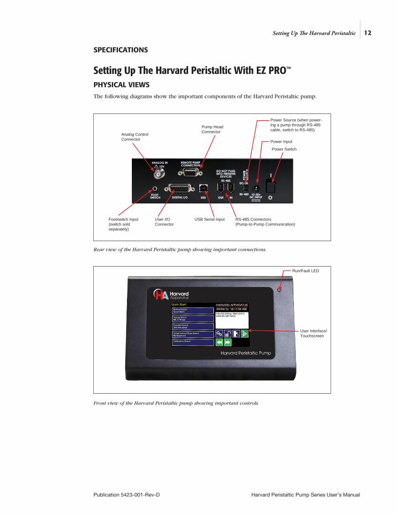
The following diagrams show the important components of the Harvard Peristaltic pump.
Rear view of the Harvard Peristaltic pump showing important connections.
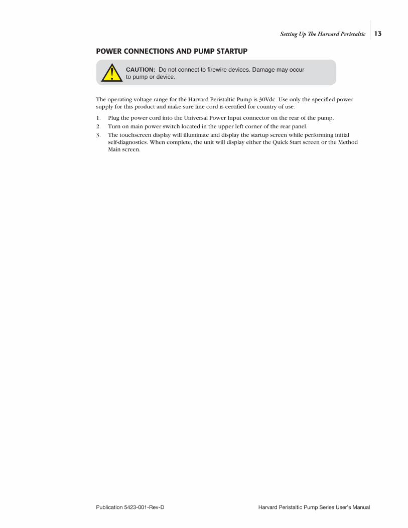
Front view of the Harvard Peristaltic pump showing important controls.
Setting Up The Harvard Peristaltic
Analog Control Connector
Pump Head Connector
Power Source (when power-ing a pump through RS-485 cable, switch to RS-485)
Power Switch
Power Input
RS-485 Connectors(Pump-to-Pump Communication)
USB Serial InputUser I/O Connector
Footswitch Input (switch sold separately)
Run/Fault LED
User Interface/ Touchscreen
13
Publication 5423-001-Rev-D Harvard Peristaltic Pump Series User’s Manual
Setting Up The Harvard Peristaltic
POWER CONNECTIONS AND PUMP STARTUP
The operating voltage range for the Harvard Peristaltic Pump is 30Vdc. Use only the specified power supply for this product and make sure line cord is certified for country of use.
1. Plug the power cord into the Universal Power Input connector on the rear of the pump.
2. Turn on main power switch located in the upper left corner of the rear panel.
3. The touchscreen display will illuminate and display the startup screen while performing initial self-diagnostics. When complete, the unit will display either the Quick Start screen or the Method Main screen.
CAUTION: Do not connect to firewire devices. Damage may occur to pump or device.!
NAVIGATING THE HARVARD PERISTALTIC EZ PRO™ SOFTWAREThe Harvard Peristaltic Pump uses a high resolution touchscreen with an icon-enabled graphical user interface and an advanced methods architecture to streamline simple to complex tasks.
The Harvard Peristaltic Workspace
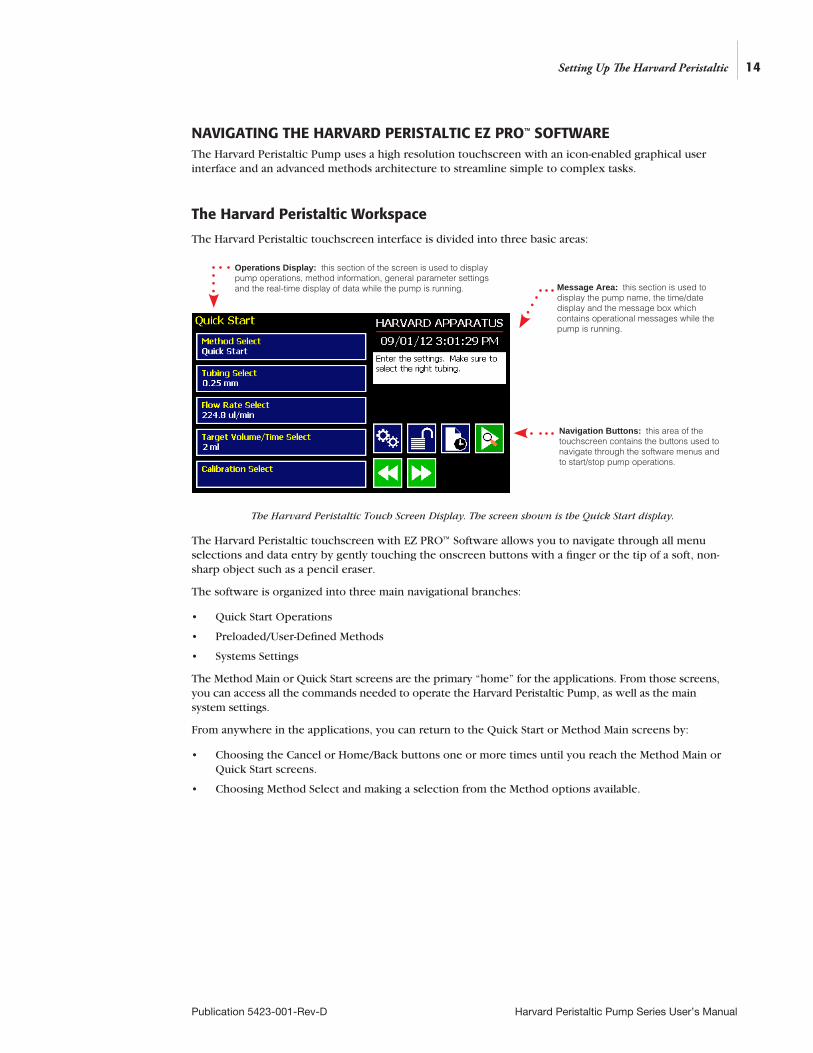
The Harvard Peristaltic touchscreen interface is divided into three basic areas:
The Harvard Peristaltic Touch Screen Display. The screen shown is the Quick Start display.
The Harvard Peristaltic touchscreen with EZ PRO™ Software allows you to navigate through all menu selections and data entry by gently touching the onscreen buttons with a finger or the tip of a soft, non-sharp object such as a pencil eraser.
The software is organized into three main navigational branches:
• Quick Start Operations
• Preloaded/User-Defined Methods
• Systems Settings
The Method Main or Quick Start screens are the primary “home” for the applications. From those screens, you can access all the commands needed to operate the Harvard Peristaltic Pump, as well as the main system settings.
From anywhere in the applications, you can return to the Quick Start or Method Main screens by:
• Choosing the Cancel or Home/Back buttons one or more times until you reach the Method Main or Quick Start screens.
• Choosing Method Select and making a selection from the Method options available.
Navigation Buttons: this area of the touchscreen contains the buttons used to navigate through the software menus and to start/stop pump operations.
Message Area: this section is used to display the pump name, the time/date display and the message box which contains operational messages while the pump is running.
Operations Display: this section of the screen is used to display pump operations, method information, general parameter settings and the real-time display of data while the pump is running.
14
Publication 5423-001-Rev-D Harvard Peristaltic Pump Series User’s Manual
Setting Up The Harvard Peristaltic
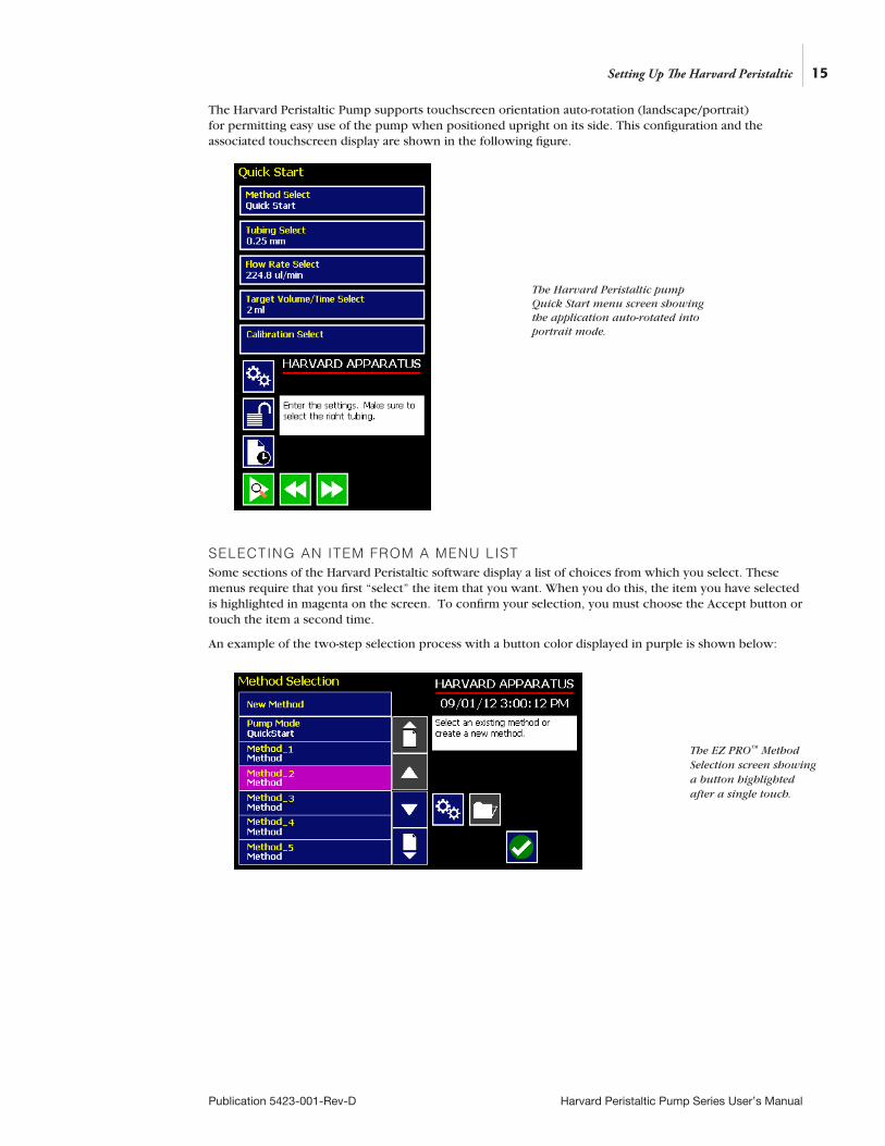
The Harvard Peristaltic Pump supports touchscreen orientation auto-rotation (landscape/portrait) for permitting easy use of the pump when positioned upright on its side. This configuration and the associated touchscreen display are shown in the following figure.
SELECTING AN ITEM FROM A MENU LISTSome sections of the Harvard Peristaltic software display a list of choices from which you select. These menus require that you first “select” the item that you want. When you do this, the item you have selected is highlighted in magenta on the screen. To confirm your selection, you must choose the Accept button or touch the item a second time.
An example of the two-step selection process with a button color displayed in purple is shown below:
15
Publication 5423-001-Rev-D Harvard Peristaltic Pump Series User’s Manual
Setting Up The Harvard Peristaltic
The EZ PRO™ Method Selection screen showing a button highlighted after a single touch.
The Harvard Peristaltic pump Quick Start menu screen showing the application auto-rotated into portrait mode.
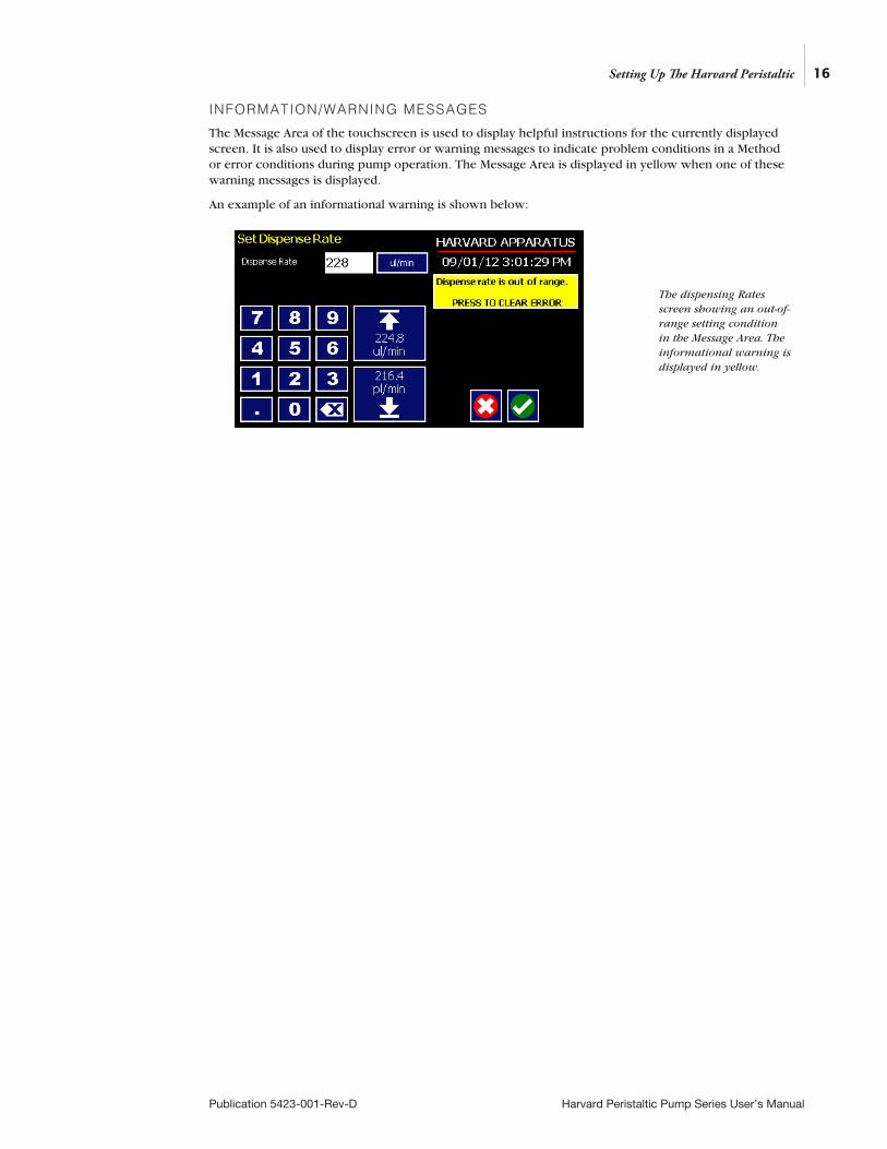
INFORMATION/WARNING MESSAGES
The Message Area of the touchscreen is used to display helpful instructions for the currently displayed screen. It is also used to display error or warning messages to indicate problem conditions in a Method or error conditions during pump operation. The Message Area is displayed in yellow when one of these warning messages is displayed.
An example of an informational warning is shown below:
16
Publication 5423-001-Rev-D Harvard Peristaltic Pump Series User’s Manual
Setting Up The Harvard Peristaltic
The dispensing Rates screen showing an out-of-range setting condition in the Message Area. The informational warning is displayed in yellow.

17
Publication 5423-001-Rev-D Harvard Peristaltic Pump Series User’s Manual
EZ PRO™ Touch Screen Button ReferenceThe following buttons are part of the Harvard Peristaltic software
Setting Up The Harvard Peristaltic
Settings: Access the settings menu used to adjust: Date and Time, Audible Alarms, Backlighting, RS-232 Communications, etc.
Fast Forward: Advances motor in the forward (clockwise) direction.
Fast Reverse: Advances the motor in the reverse (counter-colockwise) direction.
Increase Rate
Decrease Rate
Direction (CCW): Sets direction to counter clockwise.
Direction (CW): Sets direction to clockwise.
Accept: Used to accept the parameters/settings on a screen and advance to next screen in the menu.
Cancel: Used to cancel any changes/entries on a screen and return to the previous screen in the menu.
Back: Used to go back one screen.
Set Delay Parameters: Used to set the date and time values for delayed operation. This permits the pump to start automatically at a preset date and time.
Set Delay Parameters: Indicates the Delay Timer has been set. The pump will start automatically on the day/time selected.
Run Preview: Access the Method Preview screen that shows a summary of steps and operating parameters.
Run/Resume: Used to Run or Resume a Method.
Re-Run: Clears counters/timers and runs the selected method from the beginning.
Stop: Used to stop running a Method.
Clear: Clears the counters/timers.
Minimum Value Allowed: Used to select minimum value allowed.
Maximum Value Allowed: Used to select maximum value allowed.
Page Down: Used to page down in a display list.
Page Up: Used to page up in a display list.
Scroll Up: Used to scroll up in a display list.
Scroll Down: Used to scroll down in a display list.
Insert Step: Used to insert a new Step in a Method after the Step that is currently selected.
Delete Step: Used to delete the selected Step in a Method.
Move Step Up: Moves the currently selected Step in a Method up one position in the Method Order.
Move Step Down: Moves the currently selected Step in a Method down one position in the Method Order.
Copy Step: Creates a duplicate (copy) of the currently selected Step in a Method and inserts it as the last Step.
Touch Screen Unlocked: Indicates that the Touch Screen is currently unlocked. Pressing the button twice locks the Touch Screen.
Touch Screen Locked: Indicates that the Touch Screen is currently locked. Press the button and enter password to unlock the Touch Screen.
File Options: Access the File Options menu that is used to manage the list of Methods and to export Method information to an externally linked pump or to a connected computer.
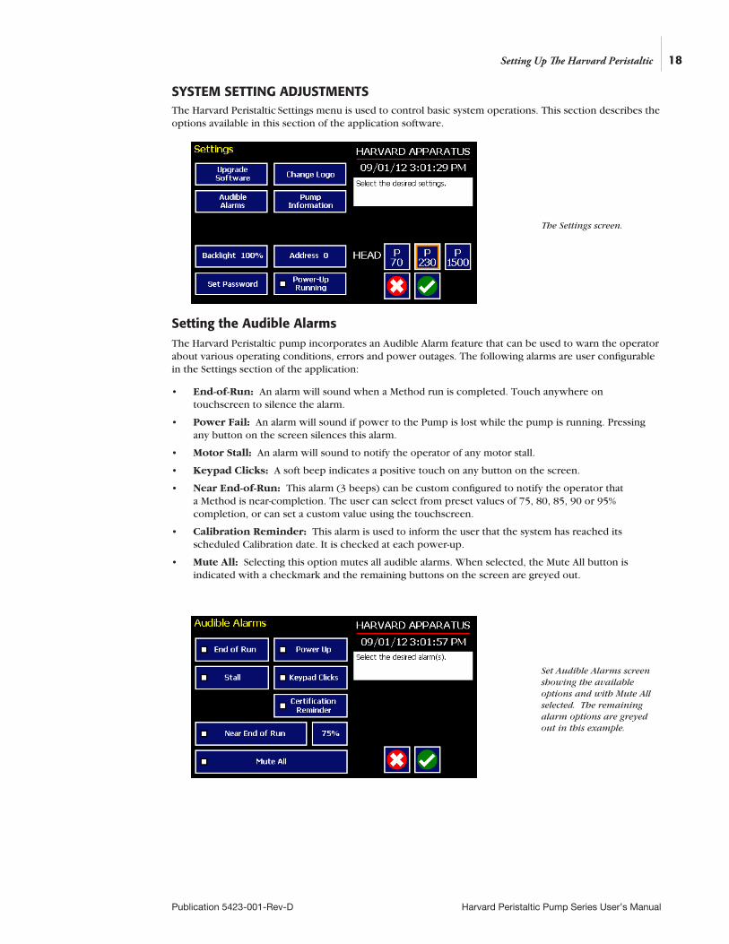
SYSTEM SETTING ADJUSTMENTSThe Harvard Peristaltic Settings menu is used to control basic system operations. This section describes the options available in this section of the application software.
Setting the Audible AlarmsThe Harvard Peristaltic pump incorporates an Audible Alarm feature that can be used to warn the operator about various operating conditions, errors and power outages. The following alarms are user configurable in the Settings section of the application:
• End-of-Run: An alarm will sound when a Method run is completed. Touch anywhere on touchscreen to silence the alarm.
• Power Fail: An alarm will sound if power to the Pump is lost while the pump is running. Pressing any button on the screen silences this alarm.
• Motor Stall: An alarm will sound to notify the operator of any motor stall.
• Keypad Clicks: A soft beep indicates a positive touch on any button on the screen.
• Near End-of-Run: This alarm (3 beeps) can be custom configured to notify the operator that a Method is near-completion. The user can select from preset values of 75, 80, 85, 90 or 95% completion, or can set a custom value using the touchscreen.
• Calibration Reminder: This alarm is used to inform the user that the system has reached its scheduled Calibration date. It is checked at each power-up.
• Mute All: Selecting this option mutes all audible alarms. When selected, the Mute All button is indicated with a checkmark and the remaining buttons on the screen are greyed out.
18
Publication 5423-001-Rev-D Harvard Peristaltic Pump Series User’s Manual
Setting Up The Harvard Peristaltic
The Settings screen.
Set Audible Alarms screen showing the available options and with Mute All selected. The remaining alarm options are greyed out in this example.
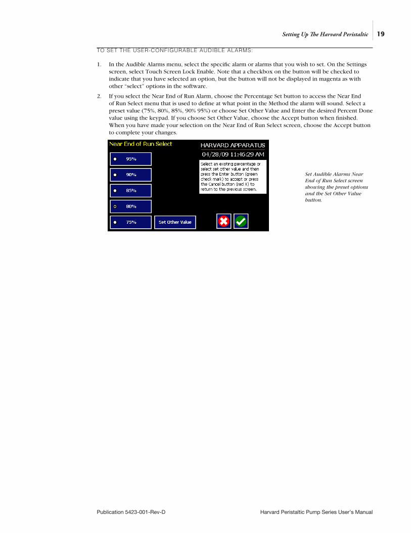
TO SET THE USER-CONFIGURABLE AUDIBLE ALARMS:
1. In the Audible Alarms menu, select the specific alarm or alarms that you wish to set. On the Settings screen, select Touch Screen Lock Enable. Note that a checkbox on the button will be checked to indicate that you have selected an option, but the button will not be displayed in magenta as with other “select” options in the software.
2. If you select the Near End of Run Alarm, choose the Percentage Set button to access the Near End of Run Select menu that is used to define at what point in the Method the alarm will sound. Select a preset value (75%, 80%, 85%, 90% 95%) or choose Set Other Value and Enter the desired Percent Done value using the keypad. If you choose Set Other Value, choose the Accept button when finished. When you have made your selection on the Near End of Run Select screen, choose the Accept button to complete your changes.
19
Publication 5423-001-Rev-D Harvard Peristaltic Pump Series User’s Manual
Setting Up The Harvard Peristaltic
Set Audible Alarms Near End of Run Select screen showing the preset options and the Set Other Value button.
20
Publication 5423-001-Rev-D Harvard Peristaltic Pump Series User’s Manual
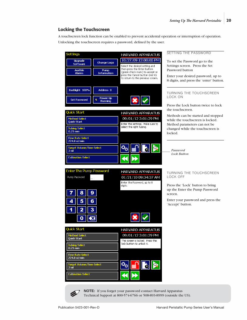
Locking the Touchscreen A touchscreen lock function can be enabled to prevent accidental operation or interruption of operation.
Unlocking the touchscreen requires a password, defined by the user.
Setting Up The Harvard Peristaltic
NOTE: If you forget your password contact Harvard Apparatus Technical Support at 800-574-6766 or 508-893-8999 (outside the US).
SETTING THE PASSWORD
To set the Password go to the Settings screen. Press the Set Password button
Enter your desired password, up to 8 digits, and press the ‘enter’ button.
TURNING THE TOUCHSCREEN LOCK ON
Press the Lock button twice to lock the touchscreen.
Methods can be started and stopped while the touchscreen is locked. Method parameters can not be changed while the touchscreen is locked.
TURNING THE TOUCHSCREEN LOCK OFF
Press the ‘Lock’ button to bring up the Enter the Pump Password screen.
Enter your password and press the ‘Accept’ button.
Password Lock Button
21
Publication 5423-001-Rev-D Harvard Peristaltic Pump Series User’s Manual
Setting the Time and DateThe Harvard Peristaltic Pump displays the date and time on each screen in the user interface. Built-in battery backups maintain the date and time even if the pump loses power or is unplugged for a period of time.
If it is necessary to set the date and time values, follow the instructions below.
TO SET THE DATE AND TIME DISPLAY:
1. From the Quick Start or Method Main screen, choose the Settings button.
2. On the Settings screen, choose the Date/Time Display box to enter the Set Date and Time screen.
3. To change the Date, select the Date button and enter the Date values using the keypad in the format defined by the date Format button to the right of the Date entry box. You can toggle between m/d/y (Month/Day/Year), d/m/y (Day/Month/Year) and y/m/d (Year/Month/day) display by successive selection of the Date Units button.
4. To change the Time, select the Time button and enter the current time in hh:mm:ss (hours:minutes:seconds) format. Select the Time Format button to toggle between AM, 24 Hour and PM values for the Time.
5. When the Date and Time values are correct, choose the Accept button to save your changes and return to the Settings screen.
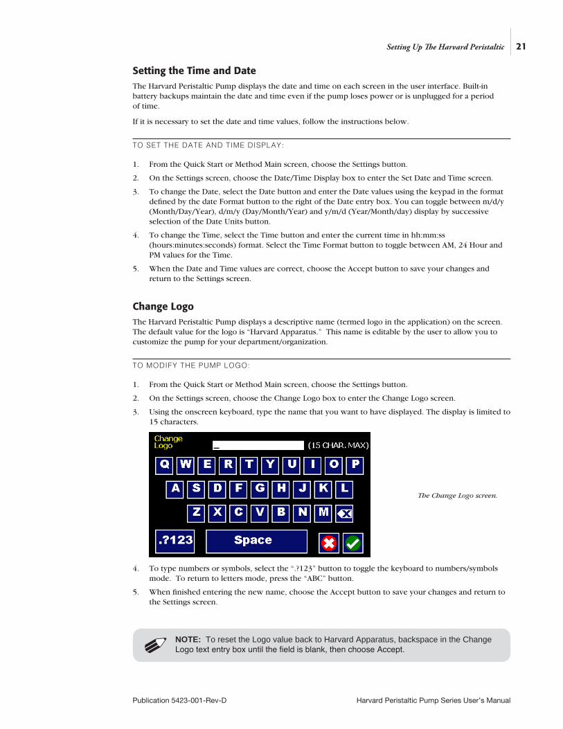
Change LogoThe Harvard Peristaltic Pump displays a descriptive name (termed logo in the application) on the screen. The default value for the logo is “Harvard Apparatus.” This name is editable by the user to allow you to customize the pump for your department/organization.
TO MODIFY THE PUMP LOGO:
1. From the Quick Start or Method Main screen, choose the Settings button.
2. On the Settings screen, choose the Change Logo box to enter the Change Logo screen.
3. Using the onscreen keyboard, type the name that you want to have displayed. The display is limited to 15 characters.
4. To type numbers or symbols, select the “.?123” button to toggle the keyboard to numbers/symbols mode. To return to letters mode, press the “ABC” button.
5. When finished entering the new name, choose the Accept button to save your changes and return to the Settings screen.
NOTE: To reset the Logo value back to Harvard Apparatus, backspace in the Change Logo text entry box until the field is blank, then choose Accept.
Setting Up The Harvard Peristaltic
The Change Logo screen.
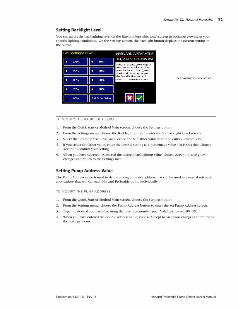
Setting Backlight LevelYou can adjust the backlighting level on the Harvard Peristaltic touchscreen to optimize viewing in your specific lighting conditions. On the Settings screen, the Backlight button displays the current setting on the button.
TO MODIFY THE BACKLIGHT LEVEL:
1. From the Quick Start or Method Main screen, choose the Settings button.
2. From the Settings menu, choose the Backlight button to enter the Set Backlight Level screen.
3. Select the desired preset level value or use the Set Other Value button to enter a custom level.
4. If you select Set Other value, enter the desired setting as a percentage value (10-100%) then choose Accept to confirm your setting.
5. When you have selected or entered the desired backlighting value, choose Accept to save your changes and return to the Settings menu.
Setting Pump Address ValueThe Pump Address value is used to define a programmable address that can be used in external software applications that will call each Harvard Peristaltic pump individually.
TO MODIFY THE PUMP ADDRESS:
1. From the Quick Start or Method Main screen, choose the Settings button.
2. From the Settings menu, choose the Pump Address button to enter the Set Pump Address screen.
3. Type the desired address value using the onscreen number pad. Valid entries are: 00 - 99.
4. When you have entered the desired address value, choose Accept to save your changes and return to the Settings menu.
22
Publication 5423-001-Rev-D Harvard Peristaltic Pump Series User’s Manual
Setting Up The Harvard Peristaltic
Set Backlight Level screen.
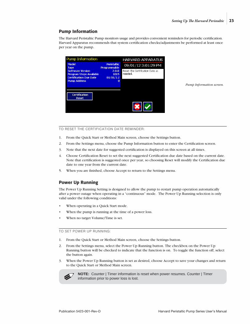
Pump InformationThe Harvard Peristaltic Pump monitors usage and provides convenient reminders for periodic certification. Harvard Apparatus recommends that system certification checks/adjustments be performed at least once per year on the pump.
TO RESET THE CERTIFICATION DATE REMINDER:
1. From the Quick Start or Method Main screen, choose the Settings button.
2. From the Settings menu, choose the Pump Information button to enter the Certification screen.
3. Note that the next date for suggested certification is displayed on this screen at all times.
4. Choose Certification Reset to set the next suggested Certification due date based on the current date. Note that certification is suggested once per year, so choosing Reset will modify the Certification due date to one year from the current date.
5. When you are finished, choose Accept to return to the Settings menu.
23
Publication 5423-001-Rev-D Harvard Peristaltic Pump Series User’s Manual
Setting Up The Harvard Peristaltic
Pump Information screen.
Power Up RunningThe Power Up Running Setting is designed to allow the pump to restart pump operation automatically after a power outage when operating in a “continuous” mode. The Power Up Running selection is only valid under the following conditions:
• When operating in a Quick Start mode.
• When the pump is running at the time of a power loss.
• When no target Volume/Time is set.
TO SET POWER UP RUNNING:
1. From the Quick Start or Method Main screen, choose the Settings button.
2. From the Settings menu, select the Power Up Running button. The checkbox on the Power Up Running button will be checked to indicate that the function is on. To toggle the function off, select the button again.
3. When the Power Up Running button is set as desired, choose Accept to save your changes and return to the Quick Start or Method Main screen.
NOTE: Counter | Timer information is reset when power resumes. Counter | Timer information prior to power loss is lost.
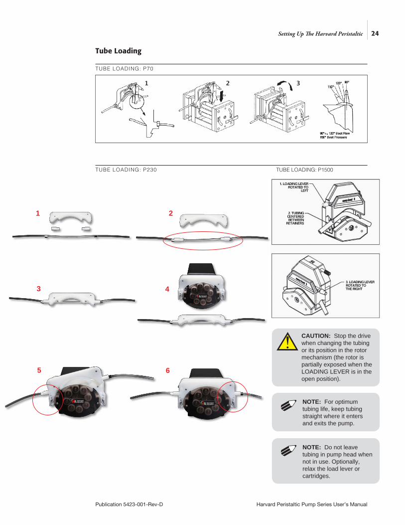
Tube Loading
TUBE LOADING: P70
TUBE LOADING: P230
24
Publication 5423-001-Rev-D Harvard Peristaltic Pump Series User’s Manual
Setting Up The Harvard Peristaltic
1 2 3
TUBE LOADING: P1500
NOTE: For optimum tubing life, keep tubing straight where it enters and exits the pump.
NOTE: Do not leave tubing in pump head when not in use. Optionally, relax the load lever or cartridges.
CAUTION: Stop the drive when changing the tubing or its position in the rotor mechanism (the rotor is partially exposed when the LOADING LEVER is in the open position).
1 2
3 4
5 6
!
25
Publication 5423-001-Rev-D Harvard Peristaltic Pump Series User’s Manual
OVERVIEW OF METHODSTo operate the Harvard Peristaltic Pump, you will define all the required parameters for withdrawing or infusing liquids through a Pump Control Method. The Pump Control Methods will be commonly referred to as Methods.
The Harvard Peristaltic is shipped with:
EZ PRO™ Quick StartEZ PRO™ Quick Start Method is designed for simple dispensing applications, pumping at a constant flow rate for either a predetermined time period until a preset volume is pumped, or running in continuous operation until stopped.
EZ PRO™ Preloaded
Preloaded Methods have been designed by Harvard Apparatus engineers to accommodate commonly employed pump control delivery protocols. These applications include the constant pressure protocol.
Preloaded Methods can be edited but not copied or deleted.
EZ PRO™ User-Defined MethodsUser-Defined Methods are created by the user through the application. To create a custom Pump Control Method, you select New Method. After naming the method, select the tubing, then define the dispensing operations desired using the available Pump Operation Profiles. User-Defined Methods can be stored on the Harvard Peristaltic up to the maximum memory capacity of approximately 1000 program steps. The user can manage the library of stored Methods using convenient touchscreen controls.
• Multiple dispenses
• Ramped or stepped flow rates
• Periodic dispensing loops
• Combination dispensing profiles (cw & ccw)
• External system control or response to external signals
Using The Harvard Peristaltic
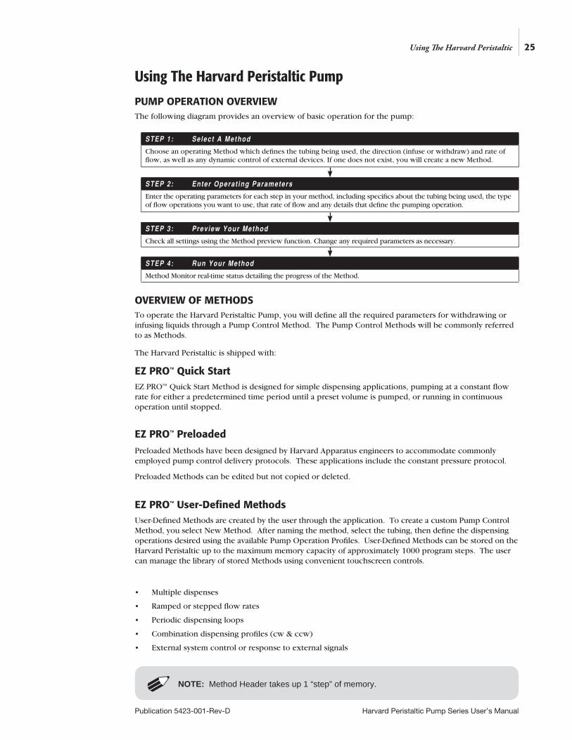
STEP 1: Se lect A Method
Choose an operating Method which defines the tubing being used, the direction (infuse or withdraw) and rate of flow, as well as any dynamic control of external devices. If one does not exist, you will create a new Method.
STEP 2: Enter Operat ing Parameters
Enter the operating parameters for each step in your method, including specifics about the tubing being used, the type of flow operations you want to use, that rate of flow and any details that define the pumping operation.
STEP 3: Prev iew Your Method
Check all settings using the Method preview function. Change any required parameters as necessary.
STEP 4: Run Your Method
Method Monitor real-time status detailing the progress of the Method.
Using The Harvard Peristaltic Pump
PUMP OPERATION OVERVIEWThe following diagram provides an overview of basic operation for the pump:
NOTE: Method Header takes up 1 “step” of memory.
26
Publication 5423-001-Rev-D Harvard Peristaltic Pump Series User’s Manual
RUNNING THE PUMP
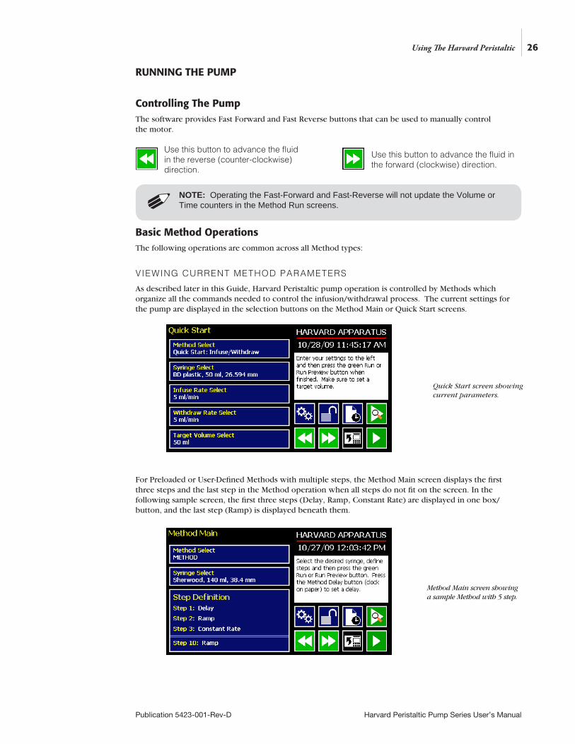
Controlling The Pump The software provides Fast Forward and Fast Reverse buttons that can be used to manually control the motor.
Basic Method OperationsThe following operations are common across all Method types:
VIEWING CURRENT METHOD PARAMETERS
As described later in this Guide, Harvard Peristaltic pump operation is controlled by Methods which organize all the commands needed to control the infusion/withdrawal process. The current settings for the pump are displayed in the selection buttons on the Method Main or Quick Start screens.
For Preloaded or User-Defined Methods with multiple steps, the Method Main screen displays the first three steps and the last step in the Method operation when all steps do not fit on the screen. In the following sample screen, the first three steps (Delay, Ramp, Constant Rate) are displayed in one box/button, and the last step (Ramp) is displayed beneath them.
NOTE: Operating the Fast-Forward and Fast-Reverse will not update the Volume or Time counters in the Method Run screens.
Use this button to advance the fluid in the reverse (counter-clockwise) direction.
Use this button to advance the fluid in the forward (clockwise) direction.
Using The Harvard Peristaltic
Quick Start screen showing current parameters.
Method Main screen showing a sample Method with 5 step.

27
Publication 5423-001-Rev-D Harvard Peristaltic Pump Series User’s Manual
TUBING SELECTION
In order to accurately control the flow rate or volume delivery of the pump, the Harvard Peristaltic Pump requires that each method include accurate setting of the tubing inside diameter. All Methods require a tube definition, either by selecting from the specifications list or by defining a new (Custom) tubing in the application.
The built-in Tubing Lookup Table provides a convenient lookup function that allows users to select from a wide variety of tubes. This Guide also includes a reference table of major common tubing diameter parameters in Appendix A.
TO SELECT A TUBE USING THE TUBING LOOKUP FUNCTION:
1. From the Quick Start or Method Main screen, choose the Tube Select button.
2. From the Tube Selection menu, double tap the button for the desired tube type to enter the tube Size Selection screen.
3. Double tap the dimensions/capacity button for the tube you will be using.
Using The Harvard Peristaltic
Tube Selection screen.
Tube Size Selection screen showing inside diameter.
28
Publication 5423-001-Rev-D Harvard Peristaltic Pump Series User’s Manual
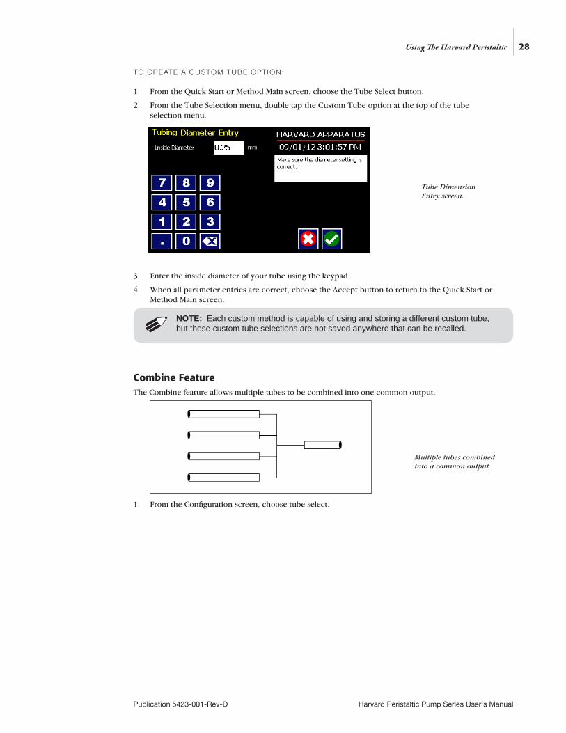
TO CREATE A CUSTOM TUBE OPTION:
1. From the Quick Start or Method Main screen, choose the Tube Select button.
2. From the Tube Selection menu, double tap the Custom Tube option at the top of the tube selection menu.
3. Enter the inside diameter of your tube using the keypad.
4. When all parameter entries are correct, choose the Accept button to return to the Quick Start or Method Main screen.
Combine FeatureThe Combine feature allows multiple tubes to be combined into one common output.
1. From the Configuration screen, choose tube select.
Using The Harvard Peristaltic
Tube Dimension Entry screen.
Multiple tubes combined into a common output.
NOTE: Each custom method is capable of using and storing a different custom tube, but these custom tube selections are not saved anywhere that can be recalled.
29
Publication 5423-001-Rev-D Harvard Peristaltic Pump Series User’s Manual
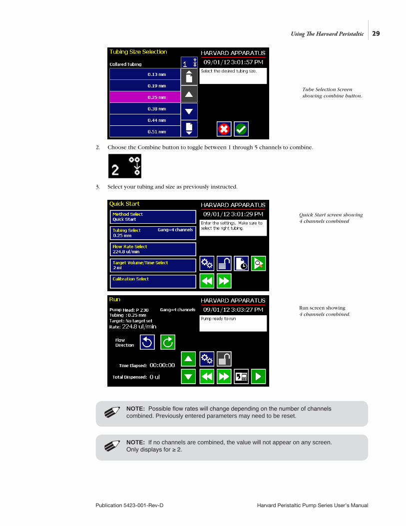
2. Choose the Combine button to toggle between 1 through 5 channels to combine.
3. Select your tubing and size as previously instructed.
Using The Harvard Peristaltic
Tube Selection Screen showing combine button.
Quick Start screen showing 4 channels combined
NOTE: Possible flow rates will change depending on the number of channels combined. Previously entered parameters may need to be reset.NOTE: If no channels are combined, the value will not appear on any screen. Only displays for ≥ 2.
Run screen showing 4 channels combined.

30
Publication 5423-001-Rev-D Harvard Peristaltic Pump Series User’s Manual
Tubing Run-in
New tubing or tubing that has been idle for extended periods, should be run-in prior to use. The pump comes standard with Methods to complete this task. The method run time is 15 minutes.
Tube Calibration
1. From the Quick Start screen, make appropriate selections for tubing size and flow rate.
2. Insert appropriate tubing into Pump Head.
3. Insert tube inlet into supply fluid.
4. Press and hold the prime button to prime the tubing. Priming will stop when the button is released.
5. Insert tube outlet into a container to be placed on a scale. The weight to volume conversion for water is 1 gram= 1 ml.
6. Press the run button. The drive will run until stopped by the user.
WARNING: Any tube size that meets the diameter specifications for the appropriate pump head can be used. DO NOT change the Method to alter the tubing displayed. It will display the max tube size for the head.
Using The Harvard Peristaltic
Quick Start Screen
Method Selection screen showing tube run-in methods for the different pump heads
NOTE: See previous section for tubing break-in procedure.
NOTE: The pumping direction for calibration is always clockwise.
!
31
Publication 5423-001-Rev-D Harvard Peristaltic Pump Series User’s Manual
Using The Harvard Peristaltic
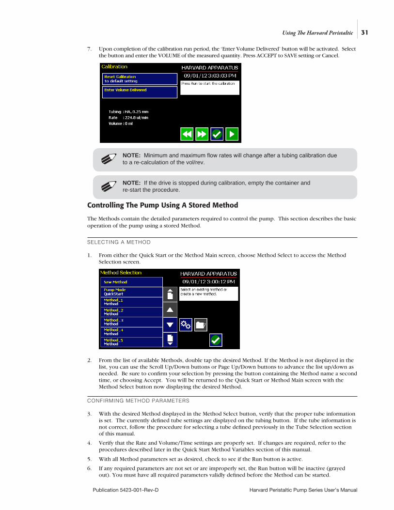
7. Upon completion of the calibration run period, the ‘Enter Volume Delivered’ button will be activated. Select the button and enter the VOLUME of the measured quantity. Press ACCEPT to SAVE setting or Cancel.
Controlling The Pump Using A Stored Method
The Methods contain the detailed parameters required to control the pump. This section describes the basic operation of the pump using a stored Method.
SELECTING A METHOD
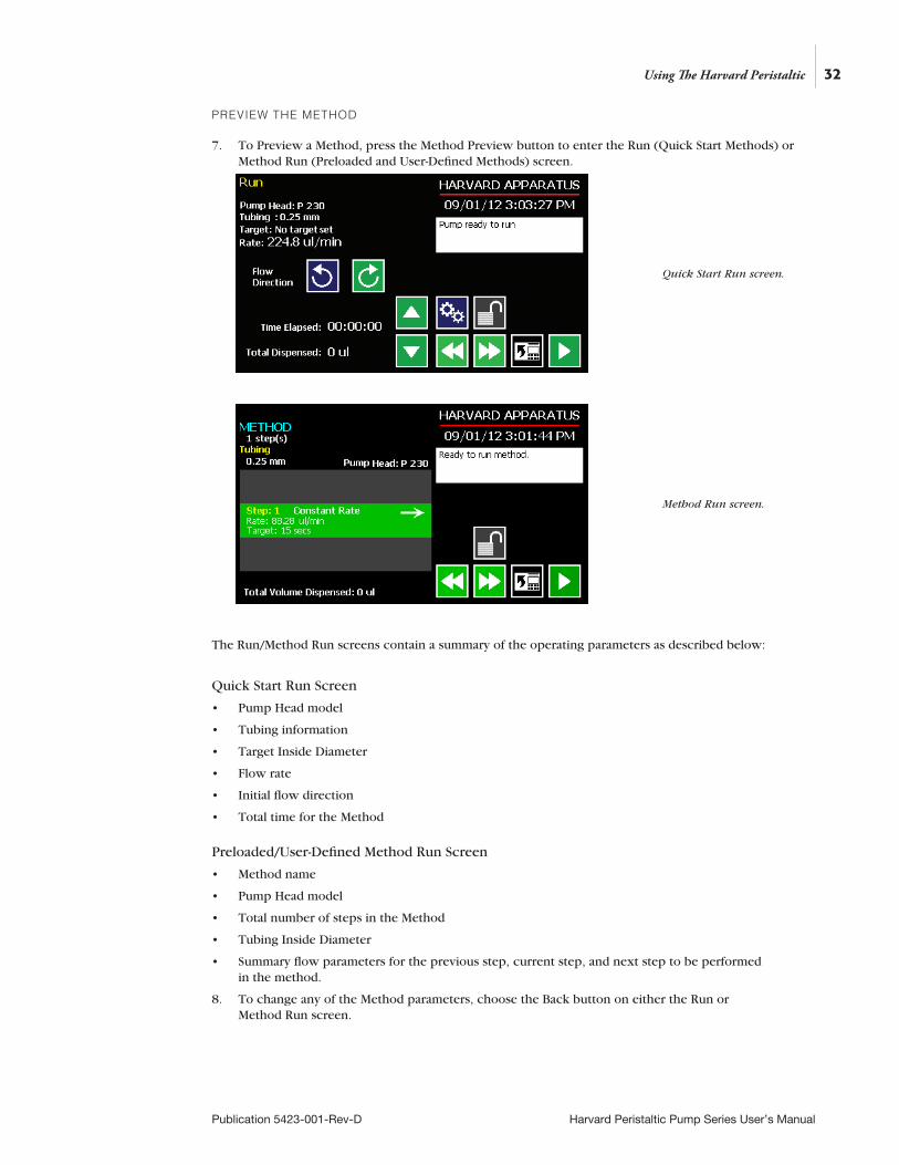
1. From either the Quick Start or the Method Main screen, choose Method Select to access the Method Selection screen.
2. From the list of available Methods, double tap the desired Method. If the Method is not displayed in the list, you can use the Scroll Up/Down buttons or Page Up/Down buttons to advance the list up/down as needed. Be sure to confirm your selection by pressing the button containing the Method name a second time, or choosing Accept. You will be returned to the Quick Start or Method Main screen with the Method Select button now displaying the desired Method.
CONFIRMING METHOD PARAMETERS
3. With the desired Method displayed in the Method Select button, verify that the proper tube information is set. The currently defined tube settings are displayed on the tubing button. If the tube information is not correct, follow the procedure for selecting a tube defined previously in the Tube Selection section of this manual.
4. Verify that the Rate and Volume/Time settings are properly set. If changes are required, refer to the procedures described later in the Quick Start Method Variables section of this manual.
5. With all Method parameters set as desired, check to see if the Run button is active.
6. If any required parameters are not set or are improperly set, the Run button will be inactive (grayed out). You must have all required parameters validly defined before the Method can be started.
NOTE: If the drive is stopped during calibration, empty the container and re-start the procedure.
NOTE: Minimum and maximum flow rates will change after a tubing calibration due to a re-calculation of the vol/rev.
32
Publication 5423-001-Rev-D Harvard Peristaltic Pump Series User’s Manual
PREVIEW THE METHOD
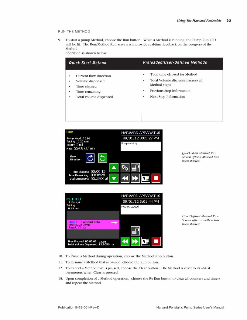
7. To Preview a Method, press the Method Preview button to enter the Run (Quick Start Methods) or Method Run (Preloaded and User-Defined Methods) screen.
The Run/Method Run screens contain a summary of the operating parameters as described below:
Quick Start Run Screen
• Pump Head model
• Tubing information
• Target Inside Diameter
• Flow rate
• Initial flow direction
• Total time for the Method
Preloaded/User-Defined Method Run Screen
• Method name
• Pump Head model
• Total number of steps in the Method
• Tubing Inside Diameter
• Summary flow parameters for the previous step, current step, and next step to be performed in the method.
8. To change any of the Method parameters, choose the Back button on either the Run or Method Run screen.
Using The Harvard Peristaltic
Quick Start Run screen.
Method Run screen.
33
Publication 5423-001-Rev-D Harvard Peristaltic Pump Series User’s Manual
RUN THE METHOD
9. To start a pump Method, choose the Run button. While a Method is running, the Pump Run LED will be lit. The Run/Method Run screen will provide real-time feedback on the progress of the Method operation as shown below:
10. To Pause a Method during operation, choose the Method Stop button.
11. To Resume a Method that is paused, choose the Run button.
12. To Cancel a Method that is paused, choose the Clear button. The Method is reset to its initial parameters when Clear is pressed.
13. Upon completion of a Method operation, choose the Re-Run button to clear all counters and timers and repeat the Method.
Quick Star t Method
• Current flow direction
• Volume dispensed
• Time elapsed
• Time remaining
• Total volume dispensed
Preloaded/User -Def ined Methods • Total time elapsed for Method
• Total Volume dispensed across all Method steps
• Previous Step Information
• Next Step Information
Using The Harvard Peristaltic
Quick Start Method Run screen after a Method has been started.
User Defined Method Run Screen after a method has been started.
34
Publication 5423-001-Rev-D Harvard Peristaltic Pump Series User’s Manual
USING AN EZ PRO™ QUICK START METHODQuick Start Methods are designed to help you quickly and conveniently use the Harvard Peristaltic for simple dispensing applications. Each Quick Start Method requires a minimal number of user entries to operate.
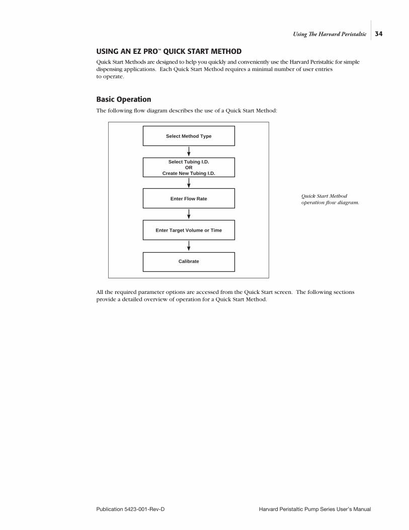
Basic OperationThe following flow diagram describes the use of a Quick Start Method:
All the required parameter options are accessed from the Quick Start screen. The following sections provide a detailed overview of operation for a Quick Start Method.
Select Method Type
Enter Flow Rate
Select Tubing I.D. OR
Create New Tubing I.D.
Enter Target Volume or Time
Using The Harvard Peristaltic
Quick Start Method operation flow diagram.
Calibrate
35
Publication 5423-001-Rev-D Harvard Peristaltic Pump Series User’s Manual
Quick Start Method Variables
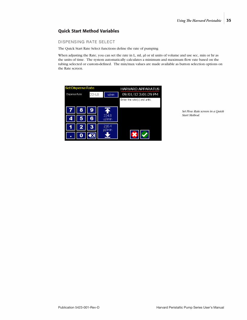
DISPENSING RATE SELECT
The Quick Start Rate Select functions define the rate of pumping
When adjusting the Rate, you can set the rate in L, ml, µl or nl units of volume and use sec, min or hr as the units of time. The system automatically calculates a minimum and maximum flow rate based on the tubing selected or custom-defined. The min/max values are made available as button selection options on the Rate screen.
Using The Harvard Peristaltic
Set Flow Rate screen in a Quick Start Method.

36
Publication 5423-001-Rev-D Harvard Peristaltic Pump Series User’s Manual
TO SET THE RATE:
1. From the Quick Start or Method Main screen, choose the Rate Select button.
2. On the Set Rate screen, enter the desired rate value using the keypad or select the Minimum or Maximum Rate button.
3. If the Units of Rate are not correct for your application, choose the Units button.
4. On the Units Selection screen, select the unit of measure (L, ml, µl or nl) and the unit of time (sec, min, hr) as appropriate, then choose Accept to confirm your selections.
5. When all parameters are correctly set on the Rate screen, choose Accept to confirm your settings and return to the Quick Start or Method Main screen.
TARGET VOLUME/TIME SELECT
The Target Volume/Time Select function is used to control how long the pump will operate at the set flow rate. The run time can be controlled by either pumping to a total volume pumped or the total length of time pumped.
When setting this parameter, you can choose between the following units of volume (L, ml, µl or nl) and the following units of time(sec, h:min:sec).
TO SET THE TARGET VOLUME OR TIME:
1. From the Quick Start screen, choose the Target Volume/Time Select button.
2. On the Set Target Volume or Time screen, select the Volume or Time button, as desired.
3. Enter the desired value using the keypad, or select the Maximum Volume button.
4. If the Units of Volume/Time are not correct for your application, choose the Units button to the right of the parameter entry box. For the Units of Volume, this choice takes you to the Units Selection screen. For the Units of Time option, this choice will toggle the button between sec (seconds) and h:m:s (hours:minutes:seconds). To use the h:m:s option, enter your time value in hours, minutes and seconds, separating each value with a colon.
5. If you are changing the Units of Volume, on the Units Selection screen, select the unit of measure (L, ml, µl or nl) as appropriate, then choose Accept to confirm your selection.
6. When all parameters are correctly set on the Set Target Volume or Time screen, choose Accept to confirm your settings and return to the Quick Start screen.
Using The Harvard Peristaltic
Set Target Volume/Time for setting pumping duration in a Quick Start Infuse Only Method.
37
Publication 5423-001-Rev-D Harvard Peristaltic Pump Series User’s Manual
USING AN EZ PRO™ PRELOADED/USER-DEFINED METHODThe Preloaded Methods and User-defined Methods each use the Harvard Peristaltic’s integrated tools that guide users through creation/editing of a custom Pump Control Method. Pump Control Methods consist of the following set of operating parameters:
• The Method Name
• Tubing Information
• The set of Pump Operation Profile steps that describe how the pump will control the flow of material
• Any additional commands to control the execution of the steps
• Any input/output (I/O) triggers/responses used to control external devices or respond to input signals from external devices.
Both the Preloaded and User-Defined Methods offer the user the flexibility to apply pumping profiles other than continuous rate dispenses. The Harvard Peristaltic Pump offers a menu of advanced pumping profiles, including:
• Constant Rate: a single continuous rate of flow
• Ramped Rate: a linearly changing flow rate between a starting and ending flow rate
• Stepped Rate: an evenly-stepped, changing flow rate between a starting and ending flow rate
• Pulsed Flow: an oscillating flow rate varying between a starting and a target rate
• Concentration Dispense: a measured flow rate based on delivery of a specific dosage to a recipient based on the recipient’s weight In addition, you have access to a variety of Advanced Options that allow the Harvard Peristaltic Pump to repeat, loop back or jump forward in a Method, as well as send signals to external devices or react to signals received from external devices. This package of pumping profiles and commands provides users with an extremely broad array of applications that can be easily configured without the use of complex external programming.
Using The Harvard Peristaltic
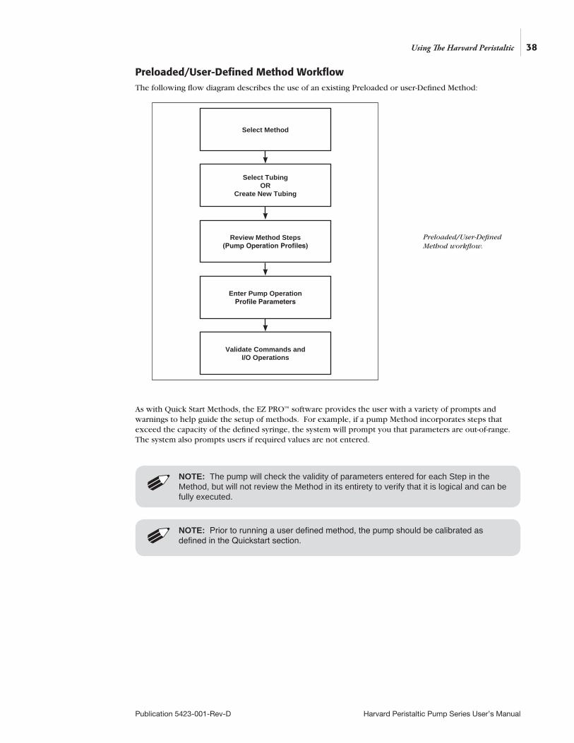
Preloaded/User-Defined Method Workflow The following flow diagram describes the use of an existing Preloaded or user-Defined Method:
As with Quick Start Methods, the EZ PRO™ software provides the user with a variety of prompts and warnings to help guide the setup of methods. For example, if a pump Method incorporates steps that exceed the capacity of the defined syringe, the system will prompt you that parameters are out-of-range. The system also prompts users if required values are not entered.
NOTE: The pump will check the validity of parameters entered for each Step in the Method, but will not review the Method in its entirety to verify that it is logical and can be fully executed.
Select Method
Review Method Steps (Pump Operation Profiles)
Select Tubing OR
Create New Tubing
Enter Pump Operation Profile Parameters
Validate Commands and I/O Operations
38
Publication 5423-001-Rev-D Harvard Peristaltic Pump Series User’s Manual
Using The Harvard Peristaltic
Preloaded/User-Defined Method workflow.
NOTE: Prior to running a user defined method, the pump should be calibrated as defined in the Quickstart section.
39
Publication 5423-001-Rev-D Harvard Peristaltic Pump Series User’s Manual
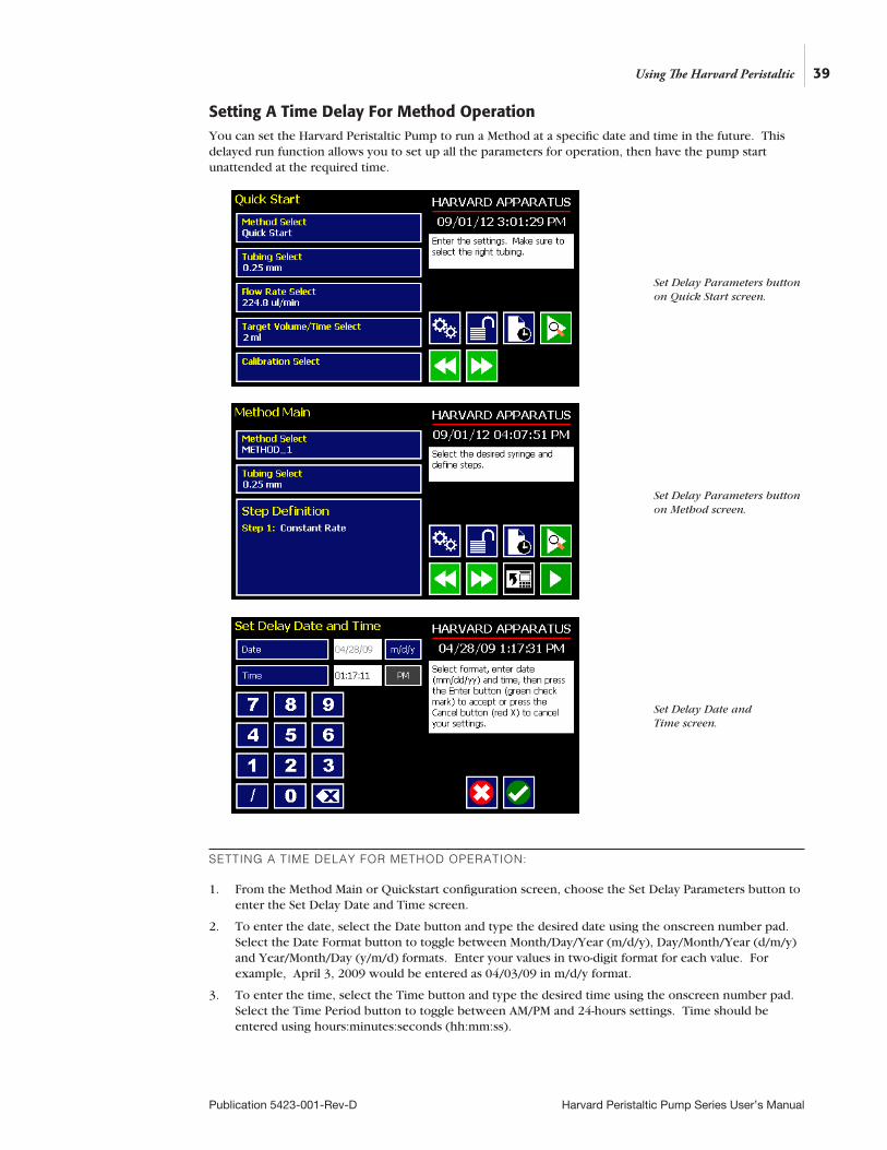
Setting A Time Delay For Method OperationYou can set the Harvard Peristaltic Pump to run a Method at a specific date and time in the future. This delayed run function allows you to set up all the parameters for operation, then have the pump start unattended at the required time.
SETTING A TIME DELAY FOR METHOD OPERATION:
1. From the Method Main or Quickstart configuration screen, choose the Set Delay Parameters button to enter the Set Delay Date and Time screen.
2. To enter the date, select the Date button and type the desired date using the onscreen number pad. Select the Date Format button to toggle between Month/Day/Year (m/d/y), Day/Month/Year (d/m/y) and Year/Month/Day (y/m/d) formats. Enter your values in two-digit format for each value. For example, April 3, 2009 would be entered as 04/03/09 in m/d/y format.
3. To enter the time, select the Time button and type the desired time using the onscreen number pad. Select the Time Period button to toggle between AM/PM and 24-hours settings. Time should be entered using hours:minutes:seconds (hh:mm:ss).
Using The Harvard Peristaltic
Set Delay Parameters button on Quick Start screen.
Set Delay Parameters button on Method screen.
Set Delay Date and Time screen.
40
Publication 5423-001-Rev-D Harvard Peristaltic Pump Series User’s Manual
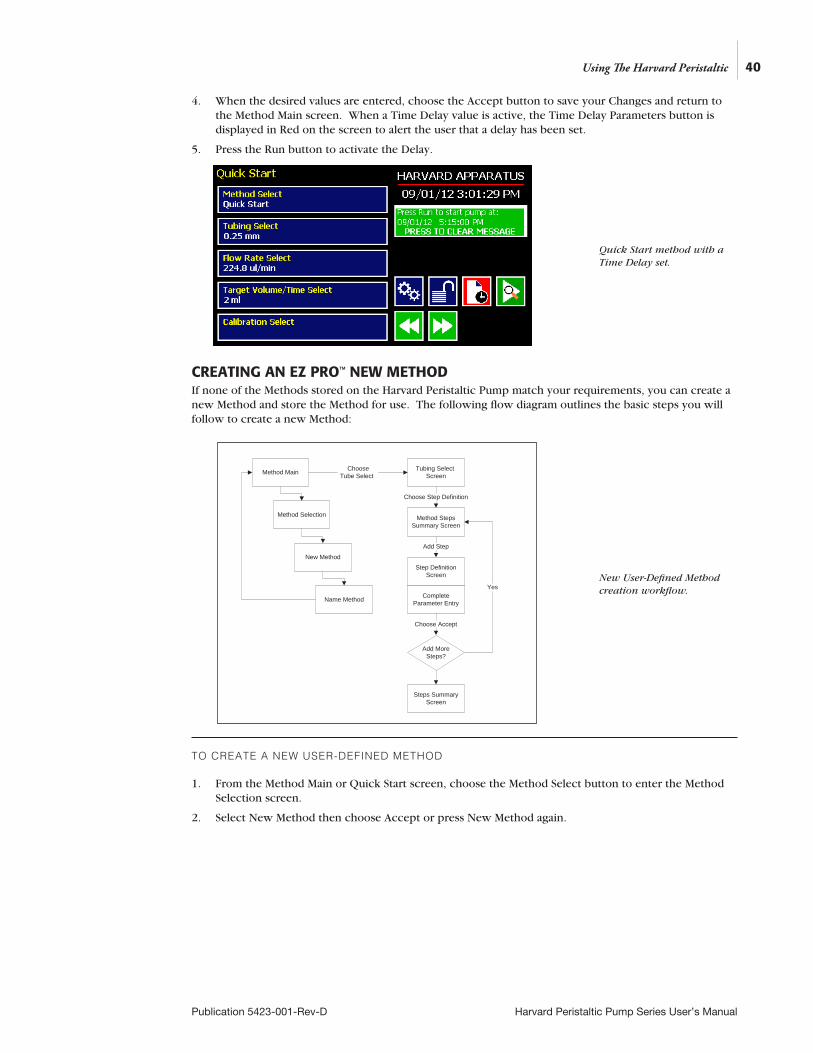
4. When the desired values are entered, choose the Accept button to save your Changes and return to the Method Main screen. When a Time Delay value is active, the Time Delay Parameters button is displayed in Red on the screen to alert the user that a delay has been set.
5. Press the Run button to activate the Delay.
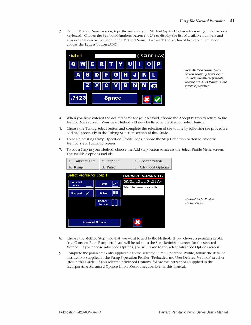
CREATING AN EZ PRO™ NEW METHODIf none of the Methods stored on the Harvard Peristaltic Pump match your requirements, you can create a new Method and store the Method for use. The following flow diagram outlines the basic steps you will follow to create a new Method:
TO CREATE A NEW USER-DEFINED METHOD
1. From the Method Main or Quick Start screen, choose the Method Select button to enter the Method Selection screen.
2. Select New Method then choose Accept or press New Method again.
Using The Harvard Peristaltic
Quick Start method with a Time Delay set.
New User-Defined Method creation workflow.
Method Main
Method Selection
New Method
Name Method
Tubing Select
Screen
Method Steps
Summary Screen
Choose
Tube Select
Choose Step Definition
Step Definition
Screen
Add Step
Complete
Parameter Entry
Steps Summary
Screen
Yes
Add More
Steps?
Choose Accept
41
Publication 5423-001-Rev-D Harvard Peristaltic Pump Series User’s Manual
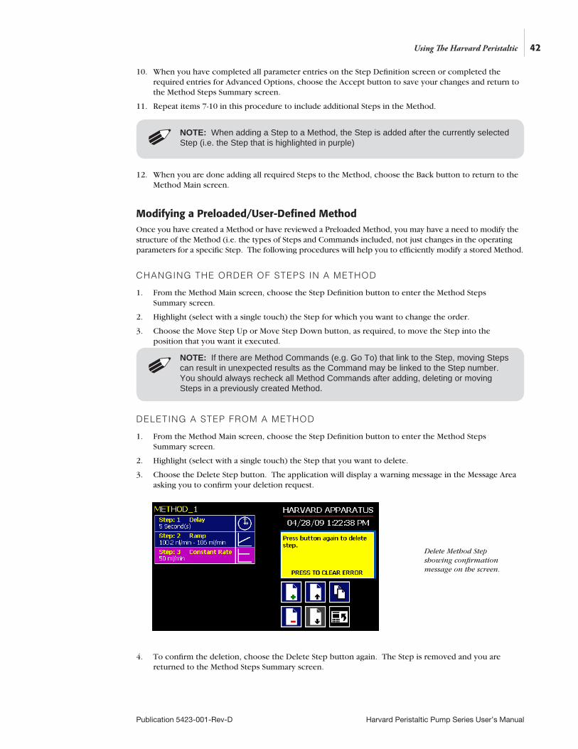
3. On the Method Name screen, type the name of your Method (up to 15 characters) using the onscreen keyboard. Choose the Symbols/Numbers button (.?123) to display the list of available numbers and symbols that can be included in the Method Name. To switch the keyboard back to letters mode, choose the Letters button (ABC).
4. When you have entered the desired name for your Method, choose the Accept button to return to the Method Main screen. Your new Method will now be listed in the Method Select button.
5. Choose the Tubing Select button and complete the selection of the tubing by following the procedure outlined previously in the Tubing Selection section of this Guide.
6. To begin creating Pump Operation Profile Steps, choose the Step Definition button to enter the Method Steps Summary screen.
7. To add a Step to your Method, choose the Add Step button to access the Select Profile Menu screen. The available options include:
8. Choose the Method Step type that you want to add to the Method. If you choose a pumping profile (e.g. Constant Rate, Ramp, etc.) you will be taken to the Step Definition screen for the selected Method. If you choose Advanced Options, you will taken to the Select Advanced Options screen.
9. Complete the parameter entry applicable to the selected Pump Operation Profile, follow the detailed instructions supplied in the Pump Operation Profiles (Preloaded and User-Defined Methods) section later in this Guide. If you selected Advanced Options, follow the instructions supplied in the Incorporating Advanced Options Into a Method section later in this manual.
Using The Harvard Peristaltic
New Method Name Entry screen showing letter keys. To view numbers/symbols, choose the .?123 button in the lower left corner.
Method Steps Profile Menu screen.
a. Constant Rate
b. Ramp
c. Stepped
d. Pulse
e. Concentration
f. Advanced Options
42
Publication 5423-001-Rev-D Harvard Peristaltic Pump Series User’s Manual
10. When you have completed all parameter entries on the Step Definition screen or completed the required entries for Advanced Options, choose the Accept button to save your changes and return to the Method Steps Summary screen.
11. Repeat items 7-10 in this procedure to include additional Steps in the Method.
12. When you are done adding all required Steps to the Method, choose the Back button to return to the Method Main screen.
Modifying a Preloaded/User-Defined MethodOnce you have created a Method or have reviewed a Preloaded Method, you may have a need to modify the structure of the Method (i.e. the types of Steps and Commands included, not just changes in the operating parameters for a specific Step. The following procedures will help you to efficiently modify a stored Method.
CHANGING THE ORDER OF STEPS IN A METHOD
1. From the Method Main screen, choose the Step Definition button to enter the Method Steps Summary screen.
2. Highlight (select with a single touch) the Step for which you want to change the order.
3. Choose the Move Step Up or Move Step Down button, as required, to move the Step into the position that you want it executed.
DELETING A STEP FROM A METHOD
1. From the Method Main screen, choose the Step Definition button to enter the Method Steps Summary screen.
2. Highlight (select with a single touch) the Step that you want to delete.
3. Choose the Delete Step button. The application will display a warning message in the Message Area asking you to confirm your deletion request.
4. To confirm the deletion, choose the Delete Step button again. The Step is removed and you are returned to the Method Steps Summary screen.
NOTE: If there are Method Commands (e.g. Go To) that link to the Step, moving Steps can result in unexpected results as the Command may be linked to the Step number. You should always recheck all Method Commands after adding, deleting or moving Steps in a previously created Method.
NOTE: When adding a Step to a Method, the Step is added after the currently selected Step (i.e. the Step that is highlighted in purple)
Using The Harvard Peristaltic
Delete Method Step showing confirmation message on the screen.
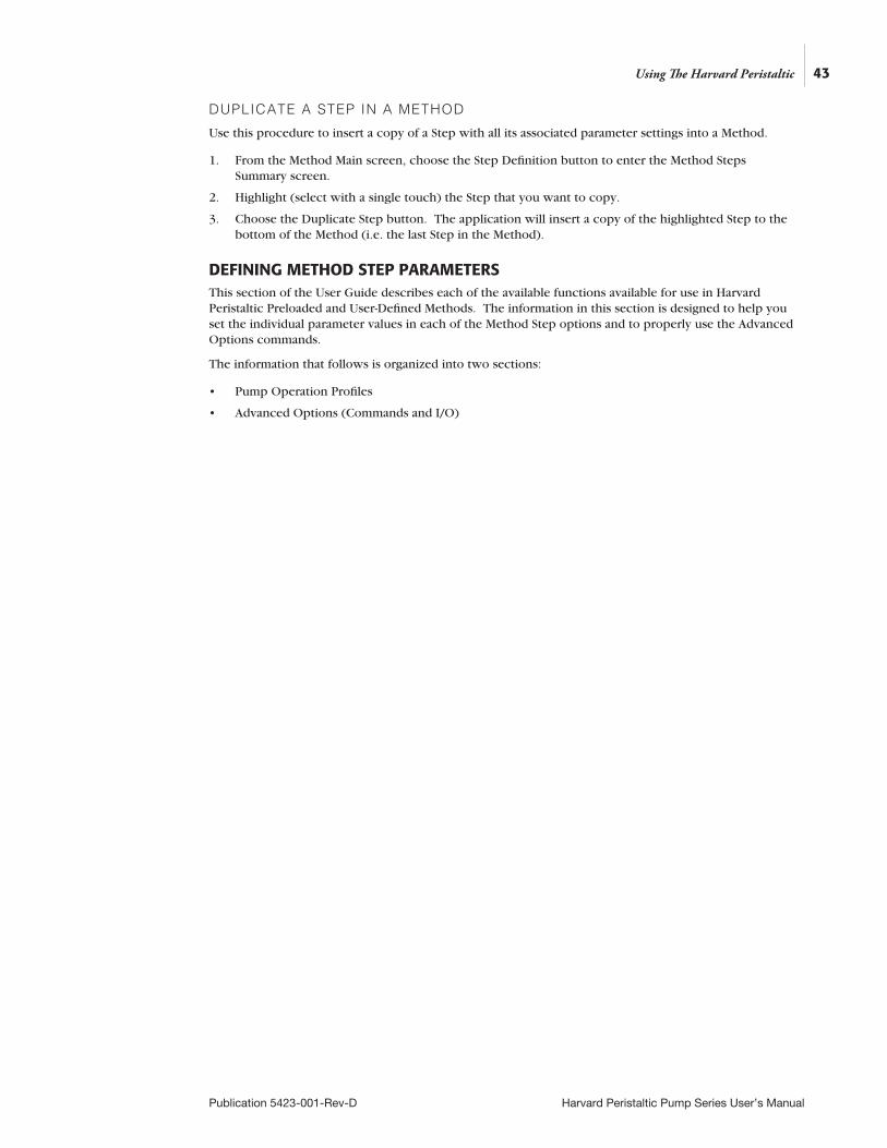
DUPLICATE A STEP IN A METHOD
Use this procedure to insert a copy of a Step with all its associated parameter settings into a Method.
1. From the Method Main screen, choose the Step Definition button to enter the Method Steps Summary screen.
2. Highlight (select with a single touch) the Step that you want to copy.
3. Choose the Duplicate Step button. The application will insert a copy of the highlighted Step to the bottom of the Method (i.e. the last Step in the Method).
DEFINING METHOD STEP PARAMETERSThis section of the User Guide describes each of the available functions available for use in Harvard Peristaltic Preloaded and User-Defined Methods. The information in this section is designed to help you set the individual parameter values in each of the Method Step options and to properly use the Advanced Options commands.
The information that follows is organized into two sections:
• Pump Operation Profiles
• Advanced Options (Commands and I/O)
43
Publication 5423-001-Rev-D Harvard Peristaltic Pump Series User’s Manual
Using The Harvard Peristaltic
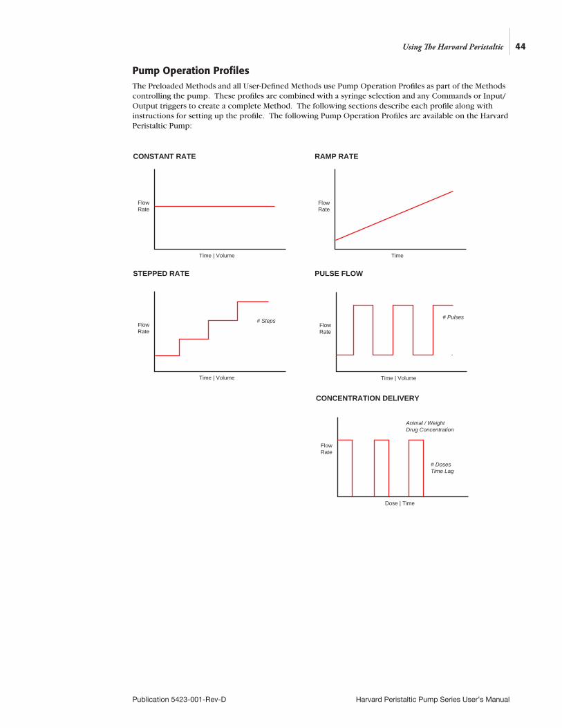
Pump Operation ProfilesThe Preloaded Methods and all User-Defined Methods use Pump Operation Profiles as part of the Methods controlling the pump. These profiles are combined with a syringe selection and any Commands or Input/Output triggers to create a complete Method. The following sections describe each profile along with instructions for setting up the profile. The following Pump Operation Profiles are available on the Harvard Peristaltic Pump:
44
Publication 5423-001-Rev-D Harvard Peristaltic Pump Series User’s Manual
Using The Harvard Peristaltic
RAMP RATE
Flow Rate
Time | Volume
Flow Rate
Time
Flow Rate
Time | Volume
Flow Rate
Time | Volume
STEPPED RATE PULSE FLOW
CONCENTRATION DELIVERY
Flow Rate
Dose | Time
# Pulses
Animal / Weight Drug Concentration
# Doses Time Lag
CONSTANT RATE
# Steps
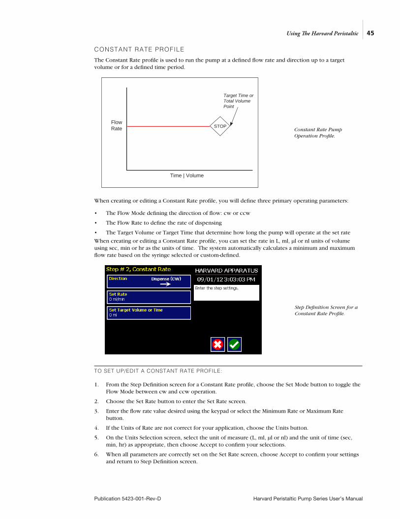
45
Publication 5423-001-Rev-D Harvard Peristaltic Pump Series User’s Manual
CONSTANT RATE PROFILE
The Constant Rate profile is used to run the pump at a defined flow rate and direction up to a target volume or for a defined time period.
When creating or editing a Constant Rate profile, you will define three primary operating parameters:
• The Flow Mode defining the direction of flow: cw or ccw
• The Flow Rate to define the rate of dispensing
• The Target Volume or Target Time that determine how long the pump will operate at the set rate
When creating or editing a Constant Rate profile, you can set the rate in L, ml, µl or nl units of volume using sec, min or hr as the units of time. The system automatically calculates a minimum and maximum flow rate based on the syringe selected or custom-defined.
TO SET UP/EDIT A CONSTANT RATE PROFILE:
1. From the Step Definition screen for a Constant Rate profile, choose the Set Mode button to toggle the Flow Mode between cw and ccw operation.
2. Choose the Set Rate button to enter the Set Rate screen.
3. Enter the flow rate value desired using the keypad or select the Minimum Rate or Maximum Rate button.
4. If the Units of Rate are not correct for your application, choose the Units button.
5. On the Units Selection screen, select the unit of measure (L, ml, µl or nl) and the unit of time (sec, min, hr) as appropriate, then choose Accept to confirm your selections.
6. When all parameters are correctly set on the Set Rate screen, choose Accept to confirm your settings and return to Step Definition screen.
Flow Rate
Time | Volume
Target Time or Total Volume Point
Using The Harvard Peristaltic
Step Definition Screen for a Constant Rate Profile.
Constant Rate Pump Operation Profile.
STOP
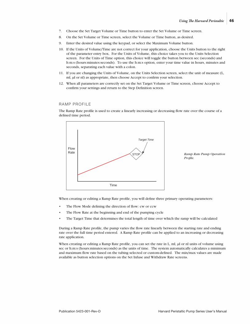
46
Publication 5423-001-Rev-D Harvard Peristaltic Pump Series User’s Manual
7. Choose the Set Target Volume or Time button to enter the Set Volume or Time screen.
8. On the Set Volume or Time screen, select the Volume or Time button, as desired.
9. Enter the desired value using the keypad, or select the Maximum Volume button.
10. If the Units of Volume/Time are not correct for your application, choose the Units button to the right of the parameter entry box. For the Units of Volume, this choice takes you to the Units Selection screen. For the Units of Time option, this choice will toggle the button between sec (seconds) and h:m:s (hours:minutes:seconds). To use the h:m:s option, enter your time value in hours, minutes and seconds, separating each value with a colon.
11. If you are changing the Units of Volume, on the Units Selection screen, select the unit of measure (L, ml, µl or nl) as appropriate, then choose Accept to confirm your selection.
12. When all parameters are correctly set on the Set Target Volume or Time screen, choose Accept to confirm your settings and return to the Step Definition screen.
RAMP PROFILE
The Ramp Rate profile is used to create a linearly increasing or decreasing flow rate over the course of a defined time period.
When creating or editing a Ramp Rate profile, you will define three primary operating parameters:
• The Flow Mode defining the direction of flow: cw or ccw
• The Flow Rate at the beginning and end of the pumping cycle
• The Target Time that determines the total length of time over which the ramp will be calculated
During a Ramp Rate profile, the pump varies the flow rate linearly between the starting rate and ending rate over the full time period entered. A Ramp Rate profile can be applied to an increasing or decreasing rate application.
When creating or editing a Ramp Rate profile, you can set the rate in L, ml, µl or nl units of volume using sec or h:m:s (hours:minutes:seconds) as the units of time. The system automatically calculates a minimum and maximum flow rate based on the tubing selected or custom-defined. The min/max values are made available as button selection options on the Set Infuse and Withdraw Rate screens.
Flow Rate
Time
STOP
Target Time
Using The Harvard Peristaltic
Ramp Rate Pump Operation Profile.
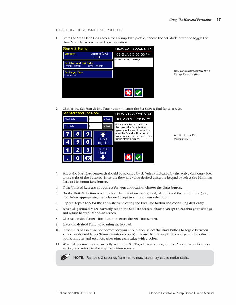
47
Publication 5423-001-Rev-D Harvard Peristaltic Pump Series User’s Manual
TO SET UP/EDIT A RAMP RATE PROFILE:
1. From the Step Definition screen for a Ramp Rate profile, choose the Set Mode button to toggle the Flow Mode between cw and ccw operation.
2. Choose the Set Start & End Rate button to enter the Set Start & End Rates screen.
3. Select the Start Rate button (it should be selected by default as indicated by the active data entry box to the right of the button). Enter the flow rate value desired using the keypad or select the Minimum Rate or Maximum Rate button.
4. If the Units of Rate are not correct for your application, choose the Units button.
5. On the Units Selection screen, select the unit of measure (L, ml, µl or nl) and the unit of time (sec, min, hr) as appropriate, then choose Accept to confirm your selections.
6. Repeat Steps 3 to 5 for the End Rate by selecting the End Rate button and continuing data entry.
7. When all parameters are correctly set on the Set Rate screen, choose Accept to confirm your settings and return to Step Definition screen.
8. Choose the Set Target Time button to enter the Set Time screen.
9. Enter the desired Time value using the keypad.
10. If the Units of Time are not correct for your application, select the Units button to toggle between sec (seconds) and h:m:s (hours:minutes:seconds). To use the h:m:s option, enter your time value in hours, minutes and seconds, separating each value with a colon.
11. When all parameters are correctly set on the Set Target Time screen, choose Accept to confirm your settings and return to the Step Definition screen.
NOTE: Ramps ≤ 2 seconds from min to max rates may cause motor stalls.
Using The Harvard Peristaltic
Step Definition screen for a Ramp Rate profile.
Set Start and End Rates screen.

48
Publication 5423-001-Rev-D Harvard Peristaltic Pump Series User’s Manual
STEPPED PROFILE
The Stepped Rate profile is used to create an increasing or decreasing flow rate that varies in a series of equal steps between a starting and ending flow rate.
When creating or editing a Stepped Rate profile, you will define four primary operating parameters:
• The Flow Mode defining the direction of flow
• The Flow Rate at the beginning and end of the pumping cycle
• The Target Time that determines the total length of time over which the stepped profile will be calculated
• The Number of Steps that will be created in the profile
During a Stepped Rate profile, the Harvard Peristaltic Pump calculates a series of equal rate increases that will vary the flow from the starting value to the ending value. You enter the Number of Steps you want to use. The Target Time defines the total length of pumping time, with the Target Time value divided equally into each stepped rate. A Stepped Rate profile can be applied to an increasing or decreasing rate application.
When creating or editing a Stepped Rate profile, you can set the rate in L, ml, µl or nl units of volume using sec or h:m:s (hours:minutes:seconds) as the units of time. The system automatically calculates a minimum and maximum flow rate based on the tubing selected or custom-defined. The min/max values are made available as button selection options on the Set screen.
Flow Rate
# Steps
Time | Volume
Using The Harvard Peristaltic
Stepped Rate Pump Operation Profile.
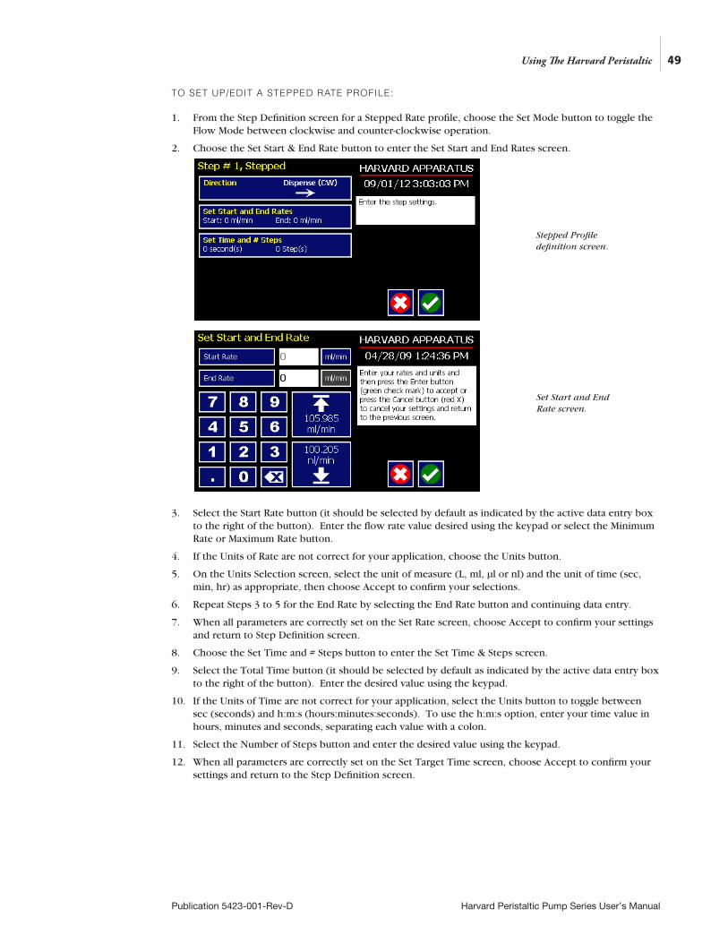
49
Publication 5423-001-Rev-D Harvard Peristaltic Pump Series User’s Manual
TO SET UP/EDIT A STEPPED RATE PROFILE:
1. From the Step Definition screen for a Stepped Rate profile, choose the Set Mode button to toggle the Flow Mode between clockwise and counter-clockwise operation.
2. Choose the Set Start & End Rate button to enter the Set Start and End Rates screen.
3. Select the Start Rate button (it should be selected by default as indicated by the active data entry box to the right of the button). Enter the flow rate value desired using the keypad or select the Minimum Rate or Maximum Rate button.
4. If the Units of Rate are not correct for your application, choose the Units button.
5. On the Units Selection screen, select the unit of measure (L, ml, µl or nl) and the unit of time (sec, min, hr) as appropriate, then choose Accept to confirm your selections.
6. Repeat Steps 3 to 5 for the End Rate by selecting the End Rate button and continuing data entry.
7. When all parameters are correctly set on the Set Rate screen, choose Accept to confirm your settings and return to Step Definition screen.
8. Choose the Set Time and # Steps button to enter the Set Time & Steps screen.
9. Select the Total Time button (it should be selected by default as indicated by the active data entry box to the right of the button). Enter the desired value using the keypad.
10. If the Units of Time are not correct for your application, select the Units button to toggle between sec (seconds) and h:m:s (hours:minutes:seconds). To use the h:m:s option, enter your time value in hours, minutes and seconds, separating each value with a colon.
11. Select the Number of Steps button and enter the desired value using the keypad.
12. When all parameters are correctly set on the Set Target Time screen, choose Accept to confirm your settings and return to the Step Definition screen.
Using The Harvard Peristaltic
Stepped Profile definition screen.
Set Start and End Rate screen.
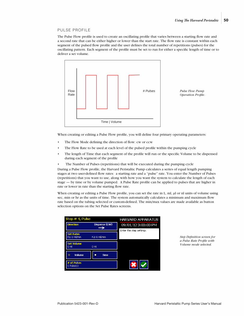
PULSE PROFILE
The Pulse Flow profile is used to create an oscillating profile that varies between a starting flow rate and a second rate that can be either higher or lower than the start rate. The flow rate is constant within each segment of the pulsed flow profile and the user defines the total number of repetitions (pulses) for the oscillating pattern. Each segment of the profile must be set to run for either a specific length of time or to deliver a set volume.
When creating or editing a Pulse Flow profile, you will define four primary operating parameters:
• The Flow Mode defining the direction of flow: cw or ccw
• The Flow Rate to be used at each level of the pulsed profile within the pumping cycle
• The length of Time that each segment of the profile will run or the specific Volume to be dispensed during each segment of the profile
• The Number of Pulses (repetitions) that will be executed during the pumping cycle
During a Pulse Flow profile, the Harvard Peristaltic Pump calculates a series of equal length pumping stages at two user-defined flow rates: a starting rate and a “pulse” rate. You enter the Number of Pulses (repetitions) that you want to use, along with how you want the system to calculate the length of each stage — by time or by volume pumped. A Pulse Rate profile can be applied to pulses that are higher in rate or lower in rate than the starting flow rate.
When creating or editing a Pulse Flow profile, you can set the rate in L, ml, µl or nl units of volume using sec, min or hr as the units of time. The system automatically calculates a minimum and maximum flow rate based on the tubing selected or custom-defined. The min/max values are made available as button selection options on the Set Pulse Rates screens.
FlowRate
Time | Volume
# Pulses
50
Publication 5423-001-Rev-D Harvard Peristaltic Pump Series User’s Manual
Using The Harvard Peristaltic
Pulse Flow Pump Operation Profile.
Step Definition screen for a Pulse Rate Profile with Volume mode selected.
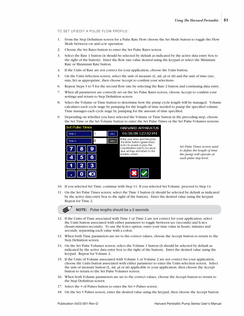
51
Publication 5423-001-Rev-D Harvard Peristaltic Pump Series User’s Manual
TO SET UP/EDIT A PULSE FLOW PROFILE:
1. From the Step Definition screen for a Pulse Rate Flow choose the Set Mode button to toggle the Flow Mode between cw and ccw operation.
2. Choose the Set Rates button to enter the Set Pulse Rates screen.
3. Select the Rate 1 button (it should be selected by default as indicated by the active data entry box to the right of the button). Enter the flow rate value desired using the keypad or select the Minimum Rate or Maximum Rate button.
4. If the Units of Rate are not correct for your application, choose the Units button.
5. On the Units Selection screen, select the unit of measure (L, ml, µl or nl) and the unit of time (sec, min, hr) as appropriate, then choose Accept to confirm your selections.
6. Repeat Steps 3 to 5 for the second flow rate by selecting the Rate 2 button and continuing data entry.
7. When all parameters are correctly set on the Set Pulse Rates screen, choose Accept to confirm your settings and return to Step Definition screen.
8. Select the Volume or Time button to determine how the pump cycle length will be managed. Volume calculates each cycle stage by pumping for the length of time needed to pump the specified volume. Time manages each cycle stage by pumping for the amount of time specified.
9. Depending on whether you have selected the Volume or Time button in the preceding step, choose the Set Time or the Set Volume button to enter the Set Pulse Times or the Set Pulse Volumes screens.
10. If you selected Set Time, continue with Step 11. If you selected Set Volume, proceed to Step 14.
11. On the Set Pulse Times screen, select the Time 1 button (it should be selected by default as indicated by the active data entry box to the right of the button). Enter the desired value using the keypad. Repeat for Time 2.
12. If the Units of Time associated with Time 1 or Time 2 are not correct for your application, select the Units button associated with either parameter to toggle between sec (seconds) and h:m:s (hours:minutes:seconds). To use the h:m:s option, enter your time value in hours, minutes and seconds, separating each value with a colon.
13. When both Time parameters are set to the correct values, choose the Accept button to return to the Step Definition screen.
14. On the Set Pulse Volumes screen, select the Volume 1 button (it should be selected by default as indicated by the active data entry box to the right of the button). Enter the desired value using the keypad. Repeat for Volume 2.
15. If the Units of Volume associated with Volume 1 or Volume 2 are not correct for your application, choose the Units button associated with either parameter to enter the Units selection screen. Select the unit of measure button (L, ml, µl or nl) applicable to your application, then choose the Accept button to return to the Set Pulse Volumes screen.
16. When both Volume parameters are set to the correct values, choose the Accept button to return to the Step Definition screen.
17. Select the # of Pulses button to enter the Set # Pulses screen.
18. On the Set # Pulses screen, enter the desired value using the keypad, then choose the Accept button.
Using The Harvard Peristaltic
Set Pulse Times screen used to define the length of time the pump will operate at each pulse step level.
NOTE: Pulse lengths should be ≥ 2 seconds

52
Publication 5423-001-Rev-D Harvard Peristaltic Pump Series User’s Manual
CONCENTRATION PROFILE
The Concentration Delivery profile is used to manage infusion of a defined concentration of drug or other liquid to a set dosage level based on the subject’s weight.
When creating or editing a Concentration Delivery profile, you will define the following operating parameters:
• The Weight of the target subject
• The Flow Rate to be used during dispensing
• The concentration of the drug or other liquid being dispensed.
• Either the target dosage or the target dispensing time — the pump automatically calculates whichever value you do not enter.
• If you wish to dispense multiple doses to the target, you can specify the number of doses along with a delay between dosings.
When creating or editing a Concentration flow profile, you can set the rate in L, ml, µl or nl units of volume using sec, min or hr as the units of time. The system automatically calculates a minimum and maximum flow rate based on the tubing selected or custom-defined. The min/max values are made available as button selection options on the Set Rate and Concentration screen. The ingredient concentration is entered in mg/ml.
Flow Rate
Animal Weight Drug Concentration# Doses
Dose | Time
Time Between Doses
Using The Harvard Peristaltic
Concentration Delivery Pump Operation Profile.
Step Definition screen for a Concentration Delivery profile.
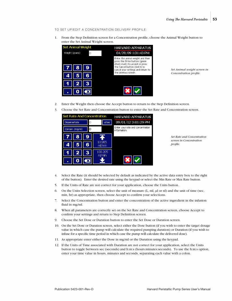
53
Publication 5423-001-Rev-D Harvard Peristaltic Pump Series User’s Manual
TO SET UP/EDIT A CONCENTRATION DELIVERY PROFILE:
1. From the Step Definition screen for a Concentration profile, choose the Animal Weight button to enter the Set Animal Weight screen.
2. Enter the Weight then choose the Accept button to return to the Step Definition screen.
3. Choose the Set Rate and Concentration button to enter the Set Rate and Concentration screen.
4. Select the Rate (it should be selected by default as indicated by the active data entry box to the right of the button). Enter the desired rate using the keypad or select the Min Rate or Max Rate button.
5. If the Units of Rate are not correct for your application, choose the Units button.
6. On the Units Selection screen, select the unit of measure (L, ml, µl or nl) and the unit of time (sec, min, hr) as appropriate, then choose Accept to confirm your selections.
7. Select the Concentration button and enter the concentration of the active ingredient in the infusion fluid in mg/ml.
8. When all parameters are correctly set on the Set Rate and Concentration screen, choose Accept to confirm your settings and return to Step Definition screen.
9. Choose the Set Dose or Duration button to enter the Set Dose or Duration screen.
10. On the Set Dose or Duration screen, select either the Dose button (if you wish to enter the target dosage value in which case the pump will calculate the required pumping duration) or Duration (if you wish to infuse for a specific time period in which case the pump will calculate the delivered dose).
11. As appropriate enter either the Dose in mg/ml or the Duration using the keypad.
12. If the Units of Time associated with Duration are not correct for your application, select the Units button to toggle between sec (seconds) and h:m:s (hours:minutes:seconds). To use the h:m:s option, enter your time value in hours, minutes and seconds, separating each value with a colon.
Using The Harvard Peristaltic
Set Animal weight screen in Concentration profile.
Set Rate and Concentration screen in Concentration profile.
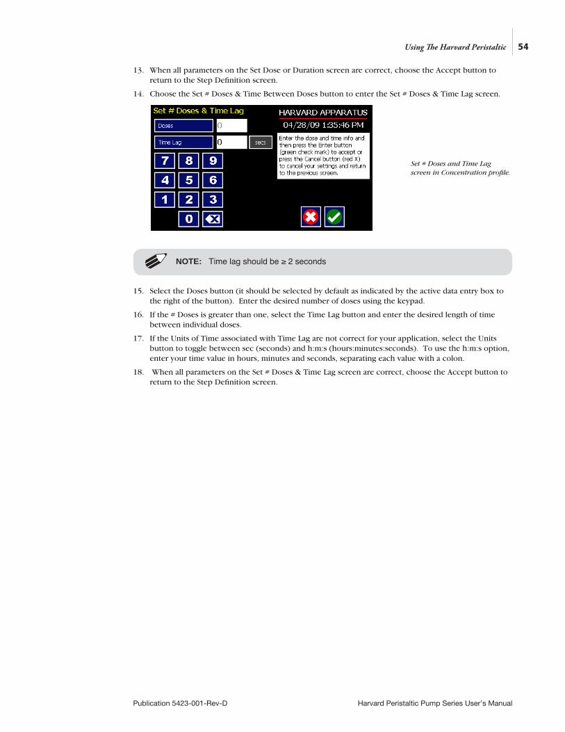
54
Publication 5423-001-Rev-D Harvard Peristaltic Pump Series User’s Manual
13. When all parameters on the Set Dose or Duration screen are correct, choose the Accept button to return to the Step Definition screen.
14. Choose the Set # Doses & Time Between Doses button to enter the Set # Doses & Time Lag screen.
15. Select the Doses button (it should be selected by default as indicated by the active data entry box to the right of the button). Enter the desired number of doses using the keypad.
16. If the # Doses is greater than one, select the Time Lag button and enter the desired length of time between individual doses.
17. If the Units of Time associated with Time Lag are not correct for your application, select the Units button to toggle between sec (seconds) and h:m:s (hours:minutes:seconds). To use the h:m:s option, enter your time value in hours, minutes and seconds, separating each value with a colon.
18. When all parameters on the Set # Doses & Time Lag screen are correct, choose the Accept button to return to the Step Definition screen.
Using The Harvard Peristaltic
Set # Doses and Time Lag screen in Concentration profile.
NOTE: Time lag should be ≥ 2 seconds
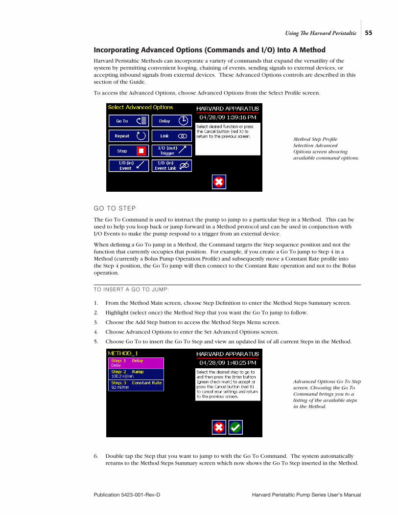
55
Publication 5423-001-Rev-D Harvard Peristaltic Pump Series User’s Manual
Incorporating Advanced Options (Commands and I/O) Into A MethodHarvard Peristaltic Methods can incorporate a variety of commands that expand the versatility of the system by permitting convenient looping, chaining of events, sending signals to external devices, or accepting inbound signals from external devices. These Advanced Options controls are described in this section of the Guide.
To access the Advanced Options, choose Advanced Options from the Select Profile screen.
GO TO STEP
The Go To Command is used to instruct the pump to jump to a particular Step in a Method. This can be used to help you loop back or jump forward in a Method protocol and can be used in conjunction with I/O Events to make the pump respond to a trigger from an external device.
When defining a Go To jump in a Method, the Command targets the Step sequence position and not the function that currently occupies that position. For example, if you create a Go To jump to Step 4 in a Method (currently a Bolus Pump Operation Profile) and subsequently move a Constant Rate profile into the Step 4 position, the Go To jump will then connect to the Constant Rate operation and not to the Bolus operation.
TO INSERT A GO TO JUMP:
1. From the Method Main screen, choose Step Definition to enter the Method Steps Summary screen.
2. Highlight (select once) the Method Step that you want the Go To jump to follow.
3. Choose the Add Step button to access the Method Steps Menu screen.
4. Choose Advanced Options to enter the Set Advanced Options screen.
5. Choose Go To to insert the Go To Step and view an updated list of all current Steps in the Method.
6. Double tap the Step that you want to jump to with the Go To Command. The system automatically returns to the Method Steps Summary screen which now shows the Go To Step inserted in the Method.
Using The Harvard Peristaltic
Method Step Profile Selection Advanced Options screen showing available command options.
Advanced Options Go To Step screen. Choosing the Go To Command brings you to a listing of the available steps in the Method.
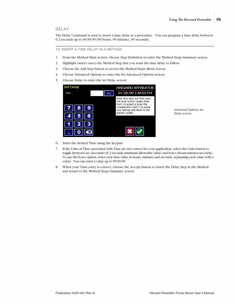
DELAY
The Delay Command is used to insert a time delay in a procedure. You can program a time delay between 0.2 seconds up to 99:99:99 (99 hours, 99 minutes, 99 seconds).
TO INSERT A TIME DELAY IN A METHOD:
1. From the Method Main screen, choose Step Definition to enter the Method Steps Summary screen.
2. Highlight (select once) the Method Step that you want the time delay to follow.
3. Choose the Add Step button to access the Method Steps Menu screen.
4. Choose Advanced Options to enter the Set Advanced Options screen.
5. Choose Delay to enter the Set Delay screen.
6. Enter the desired Time using the keypad.
7. If the Units of Time associated with Time are not correct for your application, select the Units button to toggle between sec (seconds) [0.2 seconds minimum allowable value] and h:m:s (hours:minutes:seconds). To use the h:m:s option, enter your time value in hours, minutes and seconds, separating each value with a colon. You can enter a value up to 99:99:99.
8. When your Time entry is correct, choose the Accept button to insert the Delay Step in the Method and return to the Method Steps Summary screen.
56
Publication 5423-001-Rev-D Harvard Peristaltic Pump Series User’s Manual
Using The Harvard Peristaltic
Advanced Options Set Delay screen.
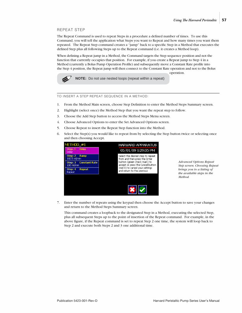
REPEAT STEP
The Repeat Command is used to repeat Steps in a procedure a defined number of times. To use this Command, you will tell the application what Steps you want to Repeat and how many times you want them repeated. The Repeat Step command creates a “jump” back to a specific Step in a Method that executes the defined Step plus all following Steps up to the Repeat command (i.e. it creates a Method loop).
When defining a Repeat jump in a Method, the Command targets the Step sequence position and not the function that currently occupies that position. For example, if you create a Repeat jump to Step 4 in a Method (currently a Bolus Pump Operation Profile) and subsequently move a Constant Rate profile into the Step 4 position, the Repeat jump will then connect to the Constant Rate operation and not to the Bolus
operation.
TO INSERT A STEP REPEAT SEQUENCE IN A METHOD:
1. From the Method Main screen, choose Step Definition to enter the Method Steps Summary screen.
2. Highlight (select once) the Method Step that you want the repeat step to follow.
3. Choose the Add Step button to access the Method Steps Menu screen.
4. Choose Advanced Options to enter the Set Advanced Options screen.
5. Choose Repeat to insert the Repeat Step function into the Method.
6. Select the Step(s) you would like to repeat from by selecting the Step button twice or selecting once and then choosing Accept.
7. Enter the number of repeats using the keypad then choose the Accept button to save your changes and return to the Method Steps Summary screen.
This command creates a loopback to the designated Step in a Method, executing the selected Step, plus all subsequent Steps up to the point of insertion of the Repeat command. For example, in the above figure, if the Repeat command is set to repeat Step 2 one time, the system will loop back to Step 2 and execute both Steps 2 and 3 one additional time.
57
Publication 5423-001-Rev-D Harvard Peristaltic Pump Series User’s Manual
Using The Harvard Peristaltic
Advanced Options Repeat Step screen. Choosing Repeat brings you to a listing of the available steps in the Method.
NOTE: Do not use nested loops (repeat within a repeat)
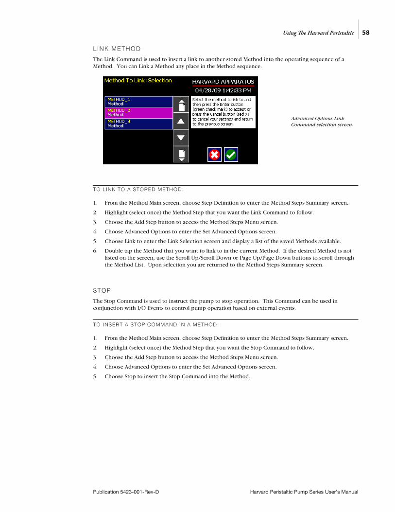
LINK METHOD
The Link Command is used to insert a link to another stored Method into the operating sequence of a Method. You can Link a Method any place in the Method sequence.
TO LINK TO A STORED METHOD:
1. From the Method Main screen, choose Step Definition to enter the Method Steps Summary screen.
2. Highlight (select once) the Method Step that you want the Link Command to follow.
3. Choose the Add Step button to access the Method Steps Menu screen.
4. Choose Advanced Options to enter the Set Advanced Options screen.
5. Choose Link to enter the Link Selection screen and display a list of the saved Methods available.
6. Double tap the Method that you want to link to in the current Method. If the desired Method is not listed on the screen, use the Scroll Up/Scroll Down or Page Up/Page Down buttons to scroll through the Method List. Upon selection you are returned to the Method Steps Summary screen.
STOP
The Stop Command is used to instruct the pump to stop operation. This Command can be used in conjunction with I/O Events to control pump operation based on external events.
TO INSERT A STOP COMMAND IN A METHOD:
1. From the Method Main screen, choose Step Definition to enter the Method Steps Summary screen.
2. Highlight (select once) the Method Step that you want the Stop Command to follow.
3. Choose the Add Step button to access the Method Steps Menu screen.
4. Choose Advanced Options to enter the Set Advanced Options screen.
5. Choose Stop to insert the Stop Command into the Method.
58
Publication 5423-001-Rev-D Harvard Peristaltic Pump Series User’s Manual
Using The Harvard Peristaltic
Advanced Options Link Command selection screen.
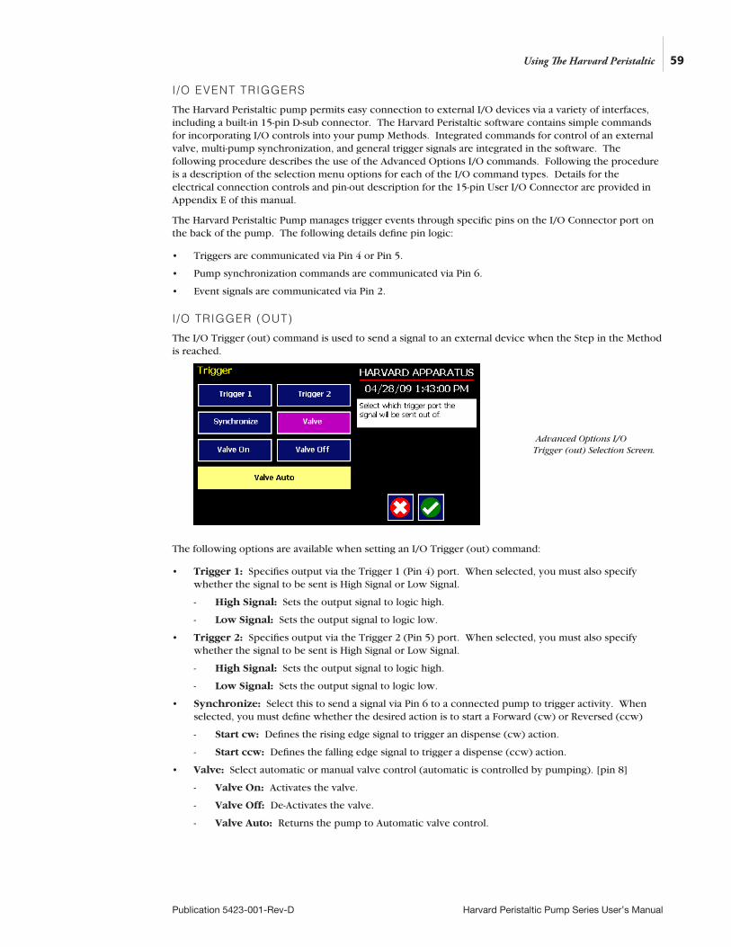
59
Publication 5423-001-Rev-D Harvard Peristaltic Pump Series User’s Manual
I /O EVENT TRIGGERS
The Harvard Peristaltic pump permits easy connection to external I/O devices via a variety of interfaces, including a built-in 15-pin D-sub connector. The Harvard Peristaltic software contains simple commands for incorporating I/O controls into your pump Methods. Integrated commands for control of an external valve, multi-pump synchronization, and general trigger signals are integrated in the software. The following procedure describes the use of the Advanced Options I/O commands. Following the procedure is a description of the selection menu options for each of the I/O command types. Details for the electrical connection controls and pin-out description for the 15-pin User I/O Connector are provided in Appendix E of this manual.
The Harvard Peristaltic Pump manages trigger events through specific pins on the I/O Connector port on the back of the pump. The following details define pin logic:
• Triggers are communicated via Pin 4 or Pin 5.
• Pump synchronization commands are communicated via Pin 6.
• Event signals are communicated via Pin 2.
I /O TRIGGER (OUT)
The I/O Trigger (out) command is used to send a signal to an external device when the Step in the Method is reached.
The following options are available when setting an I/O Trigger (out) command:
• Trigger 1: Specifies output via the Trigger 1 (Pin 4) port. When selected, you must also specify whether the signal to be sent is High Signal or Low Signal.
- High Signal: Sets the output signal to logic high.
- Low Signal: Sets the output signal to logic low.
• Trigger 2: Specifies output via the Trigger 2 (Pin 5) port. When selected, you must also specify whether the signal to be sent is High Signal or Low Signal.
- High Signal: Sets the output signal to logic high.
- Low Signal: Sets the output signal to logic low.
• Synchronize: Select this to send a signal via Pin 6 to a connected pump to trigger activity. When selected, you must define whether the desired action is to start a Forward (cw) or Reversed (ccw)
- Start cw: Defines the rising edge signal to trigger an dispense (cw) action.
- Start ccw: Defines the falling edge signal to trigger a dispense (ccw) action.
• Valve: Select automatic or manual valve control (automatic is controlled by pumping). [pin 8]
- Valve On: Activates the valve.
- Valve Off: De-Activates the valve.
- Valve Auto: Returns the pump to Automatic valve control.
Using The Harvard Peristaltic
Advanced Options I/O Trigger (out) Selection Screen.
TO INSERT AN I/O TRIGGER (OUT) COMMAND:
1. From the Method Main screen, choose Step Definition to enter the Method Steps Summary screen.
2. Highlight (select once) the Method Step that you want the I/O Trigger (Out) to follow.
3. Choose the Add Step button to access the Method Steps Menu screen.
4. Choose Advanced Options to enter the Select Advanced Options screen.
5. Choose the I/O Trigger (out) button to enter the Trigger Step Definition Screen.
6. Set your Trigger settings by choosing the appropriate option from the following sub-procedures:
a. To send a Trigger signal to an external device via Pin 4, select the Trigger 1 button. To send a Trigger signal via Pin 5, select the Trigger 2 button. Then select whether the signal will be High or Low by selecting the appropriate button.
b. To send a trigger signal to an external valve, select Valve. Then select whether the trigger will actuate (On button) or close (Off button) by selecting the appropriate button. This overrides the ‘Valve Auto’ setting, which means that the valve is controlled by a direction change. The valve will default back to ‘auto’ after leaving the Method Run screen.
c. To send a synchronization signal to a connected pump, select Synchronize. Then select whether you want to start a cw or ccw dispense by selecting the appropriate button.
7. Choose the Accept button to save your changes and return to the Method Steps Summary screen.
NOTE: When using triggers, the first step in your method should define the trigger starting level (High or Low). You may then use the trigger command to change the level as desired for your Method.
60
Publication 5423-001-Rev-D Harvard Peristaltic Pump Series User’s Manual
Using The Harvard Peristaltic
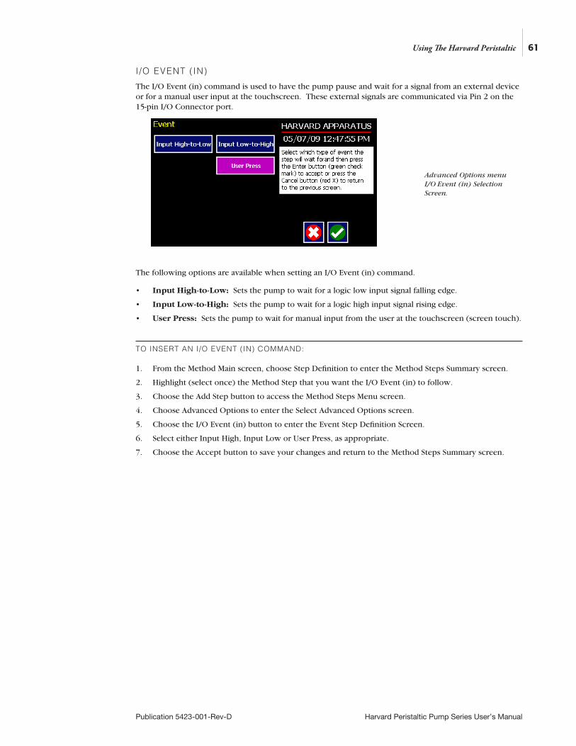
I /O EVENT ( IN)
The I/O Event (in) command is used to have the pump pause and wait for a signal from an external device or for a manual user input at the touchscreen. These external signals are communicated via Pin 2 on the 15-pin I/O Connector port.
The following options are available when setting an I/O Event (in) command.
• Input High-to-Low: Sets the pump to wait for a logic low input signal falling edge.
• Input Low-to-High: Sets the pump to wait for a logic high input signal rising edge.
• User Press: Sets the pump to wait for manual input from the user at the touchscreen (screen touch).
TO INSERT AN I/O EVENT (IN) COMMAND:
1. From the Method Main screen, choose Step Definition to enter the Method Steps Summary screen.
2. Highlight (select once) the Method Step that you want the I/O Event (in) to follow.
3. Choose the Add Step button to access the Method Steps Menu screen.
4. Choose Advanced Options to enter the Select Advanced Options screen.
5. Choose the I/O Event (in) button to enter the Event Step Definition Screen.
6. Select either Input High, Input Low or User Press, as appropriate.
7. Choose the Accept button to save your changes and return to the Method Steps Summary screen.
61
Publication 5423-001-Rev-D Harvard Peristaltic Pump Series User’s Manual
Using The Harvard Peristaltic
Advanced Options menu I/O Event (in) Selection Screen.

I /O EVENT LINK (IN)
The I/O Event Link (in) command is used to have the pump jump to a linked method if the signal is received. The external signals are communicated via Pin 2 on the 15-pin I/O Connector.
The following options are available when setting an I/O Event Link (in) command. This command requires that you have a method set with the specific actions (steps) you want to perform if the event occurs so that you can choose the Method name being linked by this command.
• Input High-to-Low: Will link to the desired method upon a logic low input signal falling edge.
• Input Low-to-High: Will link to the desired method upon a logic high input signal rising edge.
• User Press: Will link to the desired method upon a manual input.
• Motor Stall: Will link to the desired method upon a Motor Stall event.
• CCW: Will link to the desired method upon a CCW motor rotation.
• CW: Will link to the desired method upon a CW motor rotation.
TO INSERT AN I/O EVENT LINK (IN) COMMAND:
1. From the Method Main screen, choose Step Definition to enter the Method Summary screen.
2. Highlight (select once) the Method Step that you want the I/O Event Link (in) command to follow.
3. Choose the Add Step button to access the Method Steps Menu screen.
4. Choose Advanced Options to enter the Select Advanced Options screen.
5. Choose the I/O Event Link (in) button to enter the Event Link Step Definition Screen.
6. Select the desired Event type that you want to have the event associated with from the options available (Input Low, Input High, User Press, Motor Stall, CCW, CW).
7. After selecting the desired option in the Event Link screen, choose Accept to access the Method Steps Summary selection screen. Choose the Method name to jump to. To use this command, you must have defined a linkable Method.
8. Choose the Accept button to save your changes and return to the Method Steps Summary screen.
NOTE: Since the ‘Event Link’ will cause a jump (link) to a different method, be cautious not to use embedded links in your method programming.
62
Publication 5423-001-Rev-D Harvard Peristaltic Pump Series User’s Manual
Using The Harvard Peristaltic
Advanced Options I/O Event Link (in) Selection Screen.
MANAGING EZ PRO™ METHODSAll Preloaded and User-Defined Methods are stored in the Method List for ongoing use. Over time, you may want to manage previously created Methods to keep your Method List easy to navigate. In addition, the Harvard Peristaltic Pump allows you to export Method information to an externally connected pump or to a computer that will be used to control operation. This section of the Guide describes the file management facilities available on the pump.
Saving A Copy Of A MethodFollow these instructions to save a copy of a Method under a new name:
1. From the Quick Start or Method Main screen, choose the Method Select button to enter the Method Selection screen.
2. From the list of available Methods, select (press once) the Method you want to save a copy of, then choose the File Options button to enter the File Options screen.
3. Choose Save As/Copy to access the Method Name Entry screen. The current Method Name will be displayed in the text entry box.
4. On the Method Name screen, type the new name for your Method (up to 15 characters) using the onscreen keyboard. Choose the Symbols/Numbers button (.?123) to display the list of available numbers and symbols that can be included in the Method Name. To switch the keyboard back to letters mode, choose the Letters button (ABC).
5. When finished entering the new Method Name, choose Accept to save your changes and return to the File Options screen.
6. Choose Back to return to the Method Selection screen.
Renaming A Method Follow these instructions to rename a previously saved Method:
1. From the Quick Start or Method Main screen, choose the Method Select button to enter the Method Selection screen.
2. From the list of available Methods, select (press once) the Method you want to rename, then choose the File Options button to enter the File Options screen.
3. Choose Rename Method to access the Method Name Entry screen. The current Method Name will be displayed in the text entry box.
4. On the Method Name screen, type the new name for your Method using the onscreen keyboard. Choose the Symbols/Numbers button (.?123) to display the list of available numbers and symbols that can be included in the Method Name. To switch the keyboard back to letters mode, choose the Letters button (ABC).
5. When finished entering the new Method Name, choose Accept to save your changes and return to the File Options screen.
6. Choose Back to return to the Method Selection screen.
NOTE: The method management procedures outlined in this section are not available for Quick Start, Pressure or Analog Mode Methods.
63
Publication 5423-001-Rev-D Harvard Peristaltic Pump Series User’s Manual
Using The Harvard Peristaltic
Appending A MethodFollow these instructions to Append a previously created Method into a new Method:
1. From the Quick Start or Method Main screen, choose the Method Select button to enter the Method Selection screen.
2. From the list of available Methods, select (press once) the Method you want as the base Method.
3. Choose the File Options button to enter the File Options screen.
4. Choose Append to access the Method to Append screen.
5. Choose (press twice) the Method you would like to Append (attach) to your base Method. The pump will return you to the File Options screen and display a confirmation that the Method was copied.
6. Choose Back to return to the Method Selection screen.
Deleting A MethodFollow these instructions to delete a previously saved Method:
1. From the Quick Start or Method Main screen, choose the Method Select button to enter the Method Selection screen.
2. From the list of available Methods, select (press once) the Method you want to delete, then choose the File Options button to enter the File Options screen.
3. Choose Delete Method. The application will display a warning message in the Message Area asking you to confirm your deletion request.
4. Choose Delete Method again to confirm the deletion and return to the Method Selection screen.
64
Publication 5423-001-Rev-D Harvard Peristaltic Pump Series User’s Manual
Using The Harvard Peristaltic
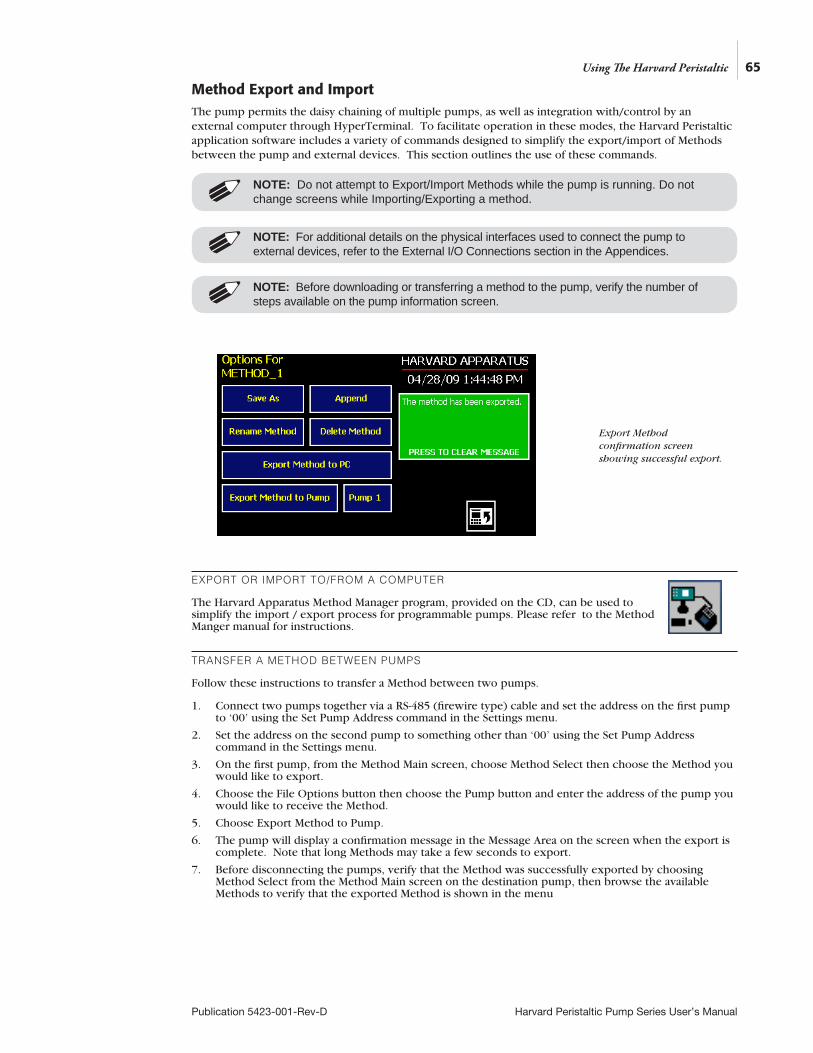
65
Publication 5423-001-Rev-D Harvard Peristaltic Pump Series User’s Manual
Method Export and ImportThe pump permits the daisy chaining of multiple pumps, as well as integration with/control by an external computer through HyperTerminal. To facilitate operation in these modes, the Harvard Peristaltic application software includes a variety of commands designed to simplify the export/import of Methods between the pump and external devices. This section outlines the use of these commands.
EXPORT OR IMPORT TO/FROM A COMPUTER
The Harvard Apparatus Method Manager program, provided on the CD, can be used to simplify the import / export process for programmable pumps. Please refer to the Method Manger manual for instructions.
TRANSFER A METHOD BETWEEN PUMPS
Follow these instructions to transfer a Method between two pumps.
1. Connect two pumps together via a RS-485 (firewire type) cable and set the address on the first pump to ‘00’ using the Set Pump Address command in the Settings menu.
2. Set the address on the second pump to something other than ‘00’ using the Set Pump Address command in the Settings menu.
3. On the first pump, from the Method Main screen, choose Method Select then choose the Method you would like to export.
4. Choose the File Options button then choose the Pump button and enter the address of the pump you would like to receive the Method.
5. Choose Export Method to Pump.
6. The pump will display a confirmation message in the Message Area on the screen when the export is complete. Note that long Methods may take a few seconds to export.
7. Before disconnecting the pumps, verify that the Method was successfully exported by choosing Method Select from the Method Main screen on the destination pump, then browse the available Methods to verify that the exported Method is shown in the menu
NOTE: Do not attempt to Export/Import Methods while the pump is running. Do not change screens while Importing/Exporting a method.
Using The Harvard Peristaltic
Export Method confirmation screen showing successful export.
NOTE: For additional details on the physical interfaces used to connect the pump to external devices, refer to the External I/O Connections section in the Appendices.
NOTE: Before downloading or transferring a method to the pump, verify the number of steps available on the pump information screen.
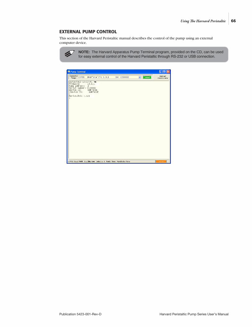
66
Publication 5423-001-Rev-D Harvard Peristaltic Pump Series User’s Manual
EXTERNAL PUMP CONTROLThis section of the Harvard Peristaltic manual describes the control of the pump using an external computer device.
Using The Harvard Peristaltic
NOTE: The Harvard Apparatus Pump Terminal program, provided on the CD, can be used for easy external control of the Harvard Peristaltic through RS-232 or USB connection.
67
Publication 5423-001-Rev-D Harvard Peristaltic Pump Series User’s Manual
PUMP CHAIN COMMANDSThe Pump Chain commands allow all pump control information to be managed from an external computer source. These commands can also be used to control a series of pumps (up to 100) from a single computer interface.
Commands are communicated to the pump via the USB port interfaces through the Pump Terminal program found on the CD or a terminal program such as HyperTerminal. In using the Pump Chain commands, you will need to assign each pump in the pump chain a unique address, using the Set Pump Address command in the Settings menu. The address range is from 00 to 99. This address value is used to identify which pump is to receive a command and which pump is responding. The first pump in the chain, the one connected to the computer, must use address 0 (zero). Configure each pump with its assigned address and baud rate as described in the Pump Settings section of this Guide.
Using Pump Chain CommandsCommands may be abbreviated to the first four letters, i.e. address would be abbreviated addr. A space must follow the command if arguments are included.
If the pump address is nonzero, the one or two-digit pump address precedes the command without any separator. For example, to set the infuse rate for pump 12, the command would look like “12irat 3.2 u/m”. If the pump address is one digit, it doesn’t have to be preceded by a 0. Note that if the USB port is used on a pump with a nonzero address, the pump address doesn’t need to be used.
Every line of the response from a pump with a nonzero address is prefixed by the two digit pump address (prefixed with a 0 if necessary) followed by a colon. No colon is used to separate the pump address from the prompt however.
In the command list below, the following convention is used:
Required parameter
[ ] Optional parameter
| Separator between parameter choices
# Numeric value without preceding zeros
### Numeric value with preceding zeros
#-# A range of values
<cr> Carriage return
<lf> Line feed
<sp> Space
[prefix] Pump address prefix in the format #: if the pump address is not zero
<prompt> Prompt (see below)
NOTE: System commands and start/stop commands can be executed from method or Quickstart screens. For parameter commands it is necessary to run from Quickstart screen.
NOTE: Once communication is established, if you manipulate the touchscreen, you must reestablish communication <CR>.
Using The Harvard Peristaltic
NOTE: To maximize communication speed [as fast as 50 ms rate changes]: (a) prefix commands with the @ symbol to turn off GUI updates (ex: @irate 100 u/m) (b) use the ‘NVRAM off’ command to turn off writes of rate to memory
68
Publication 5423-001-Rev-D Harvard Peristaltic Pump Series User’s Manual
Pump Chain Commands (continued)The following prompts are returned after a command is executed:
: The pump is idle
> The pump is dispensing in clockwise (cw) direction
< The pump is dispensing in counter-clockwise (ccw) direction
* The pump stalled
T* The target was reached
If the pump is in poll REMOTE mode, there will be no prompts or carraige returns.
If the pump is in poll ON mode, an XON character is added after the prompt.
If the pump address is nonzero, the pump address is prefixed to the prompt without a colon.
In the following list of commands:
• The pump address is prefixed to every response line followed by a colon.
• <lf>[##]<prompt> is the response unless otherwise noted.
Error messagesError messages are displayed if the entered command cannot be executed for some reason. The error message will take up two lines with the first line being the message type and the second line describing the error itself. The second line may be up to 80 characters long.
COMMAND ERRORS
Command errors are displayed when the command is unrecognized, entered in the wrong mode, or the state of the pump keeps the command from executing (i.e. using the IRUN command if a limit switch is active).
The command error has the following format:
<lf>[##:]Command error:<cr>
<lf>[##:]<sp><sp><sp>error message<cr>
<lf>[##]<prompt>
ARGUMENT ERRORS
Argument errors are displayed when a command argument is unrecognized or out of range. The argument in question will be displayed except in the case of missing arguments.
The argument error has the following format:
<lf>[##:]Argument error: [bad argument]<cr>
<lf>[##:]<sp><sp><sp>error message<cr>
<lf>[##]<prompt>
Using The Harvard Peristaltic
69
Publication 5423-001-Rev-D Harvard Peristaltic Pump Series User’s Manual
System commands ADDRESS
Sets or displays the pump address. Valid range is 0 to 99.
Command format:
address [0-99]
Query response:
<lf>[##:]Pump address is #<cr>
<lf>[##]<prompt>
Notes:
The first pump in a daisy-chain must be set to 0 CATALOG
Displays a catalog of methods stored in the pump.
Command format:
cat
Query response:
<lf>[##:]Method name Size<cr>
<lf>[##:]———————- ——<cr>
<lf>[##:]method name #<cr> This line is repeated for each file on the disk
<lf><lf>[##:]# file(s) using # steps<cr>
<lf>[##]<prompt>
Notes:
The file size is the number of steps in the method plus one for the file information header. The last line shows the number of files and the total number of steps being used on the disk.
CONFIG
Sets or displays the pump configuration.
Command format: config[config designation|value]
DELMETHOD
Deletes a method stored in the pump.
Command format: delmethod method
Using The Harvard Peristaltic
NOTE: After changing the configuration, the pump must be power cycled.
70
Publication 5423-001-Rev-D Harvard Peristaltic Pump Series User’s Manual
DIM
Sets or displays the backlight level in percent. Valid range is 0 to 100. Note that specifying 0 will turn the backlight off so that the screen will not be visible.
Command format: dim [0-100]
Query response: <lf>[##:] #%<cr>
<lf>[##]<prompt>
ECHO
Sets or displays the USB echo state. Valid states are on or off.
Command format: echo [on|off]
Query response: <lf>[##:]OFF<cr>
<lf>[##]<prompt>
or:
<lf>[##:] ON<cr>
<lf>[##]<prompt>
FREE
Displays the number of free method steps left on the disk.
Command format:
free
Query response:
<lf>[##:]# steps used<cr>
<lf>[##:]# steps free<cr>
<lf>[##:]# total steps<cr>
<lf>[##]<prompt>
The number of steps displayed is a four digit number, right justified, and padded with spaces.
Using The Harvard Peristaltic

71
Publication 5423-001-Rev-D Harvard Peristaltic Pump Series User’s Manual
FTSWITCH
Sets or displays the footswitch setting. The footswitch may be used in a toggle on or off mode (momentary), a press to run mode (falling), or a release to run mode (rising).
Command format:
ftswitch [mom|rise|fall]
Query response:
<lf>[##:]Momentary<cr>
<lf>[##]<prompt>
or:
<lf>[##:]Active high<cr>
<lf>[##]<prompt>
or:
<lf>[##:]Active low<cr>
<lf>[##]<prompt> POLL
Sets or displays the polling mode state.
When polling mode is off, prompts are displayed when an event happens, such as a target being reached.
When polling mode is on, prompts are not displayed when an event happens, and a XON character is output when the pump is ready for another command
When polling mode is in remote mode, the following occurs
• Prompts are not displayed
• Carraige returns are not displayed
• The pump address is displayed even if 0
• Echo is forced off and the echo command is illegal
Command format:
poll [on|off|remote]
Query response:
<lf>[##:] OFF<cr>
<lf>[##]<prompt>
or:
<lf>[##:] ON<cr>
<lf>[##]<prompt><xon>
or:
[##:] REMOTE<lf>
Using The Harvard Peristaltic
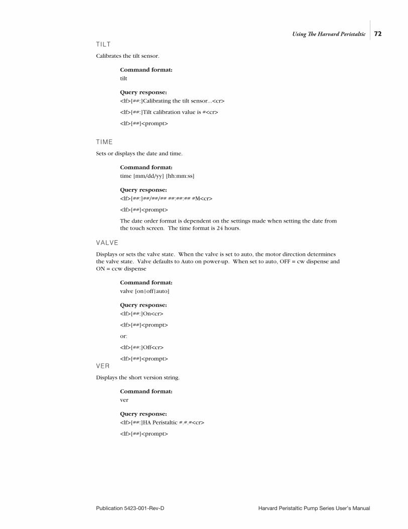
72
Publication 5423-001-Rev-D Harvard Peristaltic Pump Series User’s Manual
TILT
Calibrates the tilt sensor.
Command format:
tilt
Query response:
<lf>[##:]Calibrating the tilt sensor...<cr>
<lf>[##:]Tilt calibration value is #<cr>
<lf>[##]<prompt>
TIME
Sets or displays the date and time.
Command format:
time [mm/dd/yy] [hh:mm:ss]
Query response:
<lf>[##:]##/##/## ##:##:## #M<cr>
<lf>[##]<prompt>
The date order format is dependent on the settings made when setting the date from the touch screen. The time format is 24 hours. VALVE
Displays or sets the valve state. When the valve is set to auto, the motor direction determines the valve state. Valve defaults to Auto on power-up. When set to auto, OFF = cw dispense and ON = ccw dispense
Command format:
valve [on|off|auto]
Query response:
<lf>[##:]On<cr>
<lf>[##]<prompt>
or:
<lf>[##:]Off<cr>
<lf>[##]<prompt> VER
Displays the short version string.
Command format:
ver
Query response:
<lf>[##:]HA Peristaltic #.#.#<cr>
<lf>[##]<prompt>
Using The Harvard Peristaltic
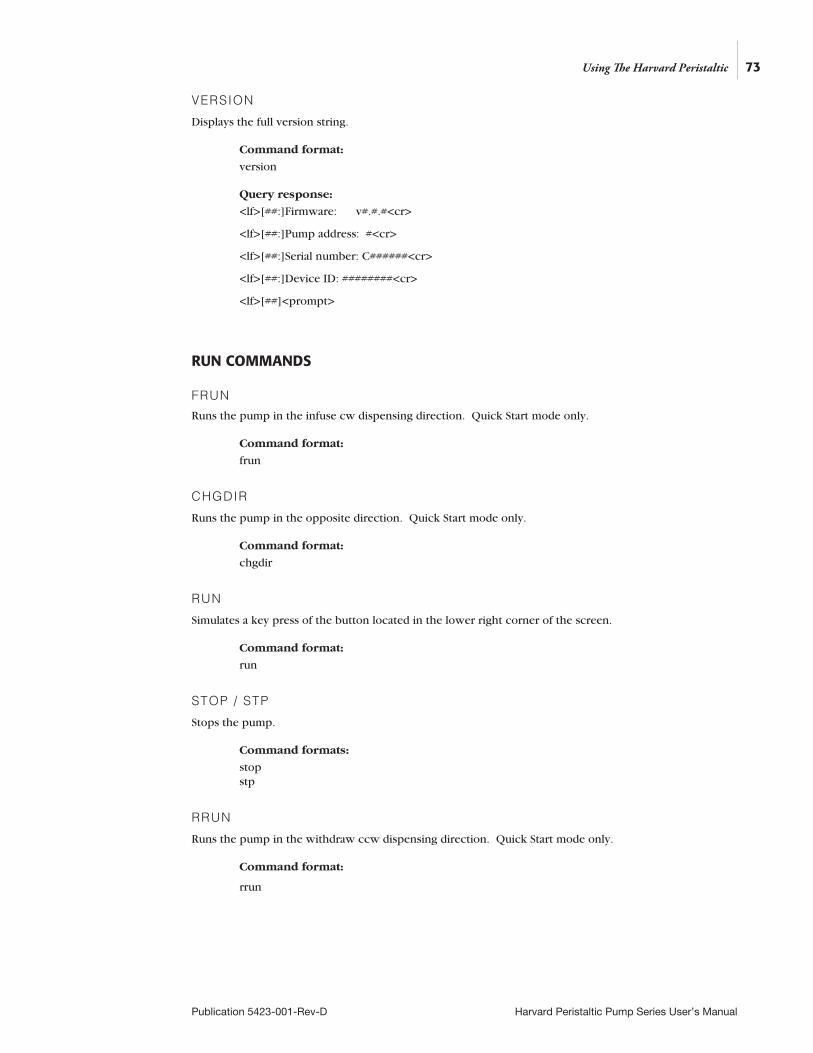
73
Publication 5423-001-Rev-D Harvard Peristaltic Pump Series User’s Manual
VERSION
Displays the full version string.
Command format:
version
Query response:
<lf>[##:]Firmware: v#.#.#<cr>
<lf>[##:]Pump address: #<cr>
<lf>[##:]Serial number: C######<cr>
<lf>[##:]Device ID: ########<cr>
<lf>[##]<prompt>
RUN COMMANDS
FRUN
Runs the pump in the infuse cw dispensing direction. Quick Start mode only.
Command format:
frun
CHGDIR
Runs the pump in the opposite direction. Quick Start mode only.
Command format:
chgdir
RUN
Simulates a key press of the button located in the lower right corner of the screen.
Command format:
run
STOP / STP
Stops the pump.
Command formats:
stop stp
RRUN
Runs the pump in the withdraw ccw dispensing direction. Quick Start mode only.
Command format:
rrun
Using The Harvard Peristaltic
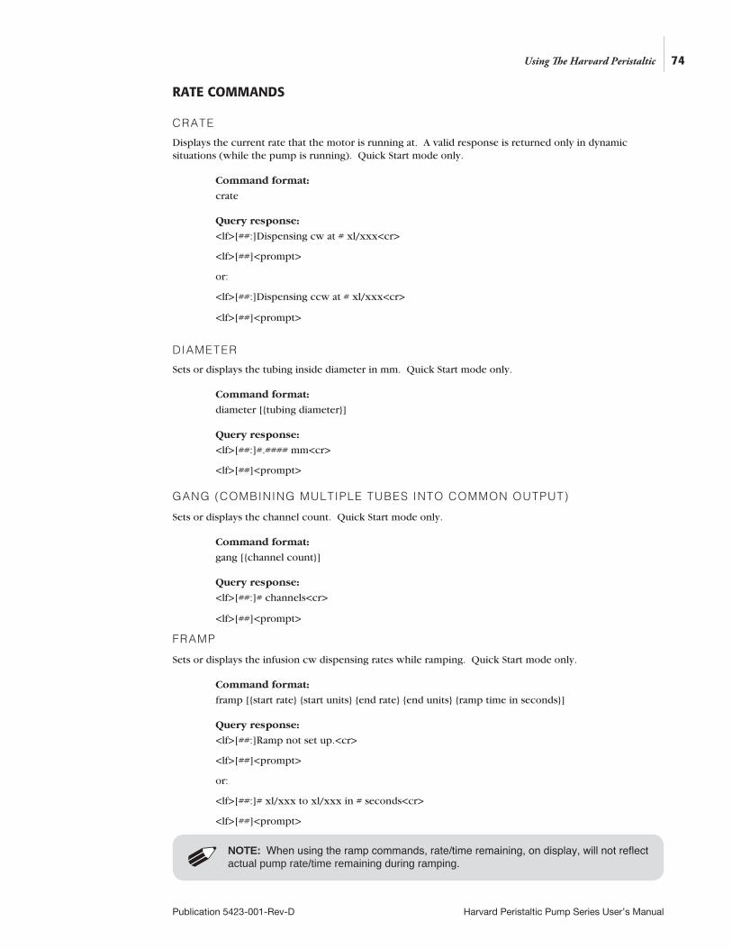
74
Publication 5423-001-Rev-D Harvard Peristaltic Pump Series User’s Manual
RATE COMMANDS
CRATE
Displays the current rate that the motor is running at. A valid response is returned only in dynamic situations (while the pump is running). Quick Start mode only.
Command format:
crate
Query response:
<lf>[##:]Dispensing cw at # xl/xxx<cr>
<lf>[##]<prompt>
or:
<lf>[##:]Dispensing ccw at # xl/xxx<cr>
<lf>[##]<prompt>
DIAMETER
Sets or displays the tubing inside diameter in mm. Quick Start mode only.
Command format:
diameter [tubing diameter]
Query response:
<lf>[##:]#.#### mm<cr>
<lf>[##]<prompt> GANG (COMBINING MULTIPLE TUBES INTO COMMON OUTPUT)
Sets or displays the channel count. Quick Start mode only.
Command format:
gang [channel count]
Query response:
<lf>[##:]# channels<cr>
<lf>[##]<prompt>
FRAMP
Sets or displays the infusion cw dispensing rates while ramping. Quick Start mode only.
Command format:
framp [start rate start units end rate end units ramp time in seconds]
Query response:
<lf>[##:]Ramp not set up.<cr>
<lf>[##]<prompt>
or:
<lf>[##:]# xl/xxx to xl/xxx in # seconds<cr>
<lf>[##]<prompt>
Using The Harvard Peristaltic
NOTE: When using the ramp commands, rate/time remaining, on display, will not reflect actual pump rate/time remaining during ramping.
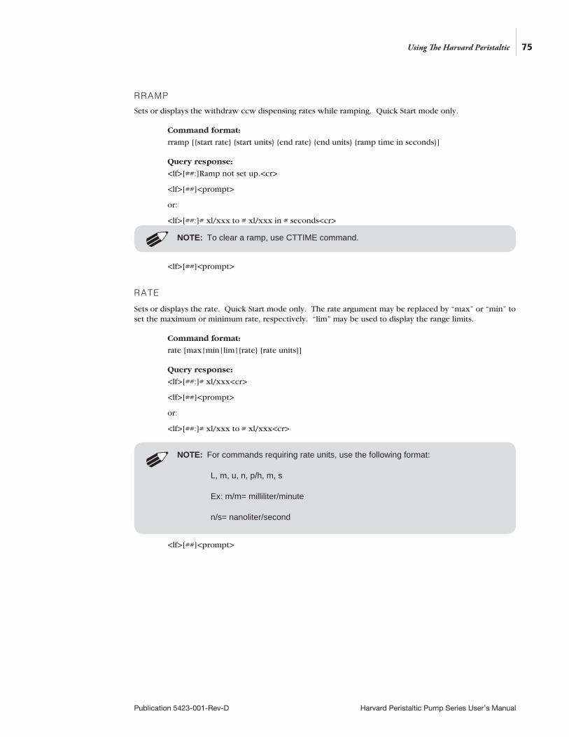
RRAMP
Sets or displays the withdraw ccw dispensing rates while ramping. Quick Start mode only.
Command format:
rramp [start rate start units end rate end units ramp time in seconds]
Query response:
<lf>[##:]Ramp not set up.<cr>
<lf>[##]<prompt>
or:
<lf>[##:]# xl/xxx to # xl/xxx in # seconds<cr>
<lf>[##]<prompt>
RATE
Sets or displays the rate. Quick Start mode only. The rate argument may be replaced by “max” or “min” to set the maximum or minimum rate, respectively. “lim” may be used to display the range limits.
Command format:
rate [max|min|lim|rate rate units]
Query response:
<lf>[##:]# xl/xxx<cr>
<lf>[##]<prompt>
or:
<lf>[##:]# xl/xxx to # xl/xxx<cr>
<lf>[##]<prompt>
75
Publication 5423-001-Rev-D Harvard Peristaltic Pump Series User’s Manual
Using The Harvard Peristaltic
NOTE: To clear a ramp, use CTTIME command.
NOTE: For commands requiring rate units, use the following format:
L, m, u, n, p/h, m, s
Ex: m/m= milliliter/minute
n/s= nanoliter/second
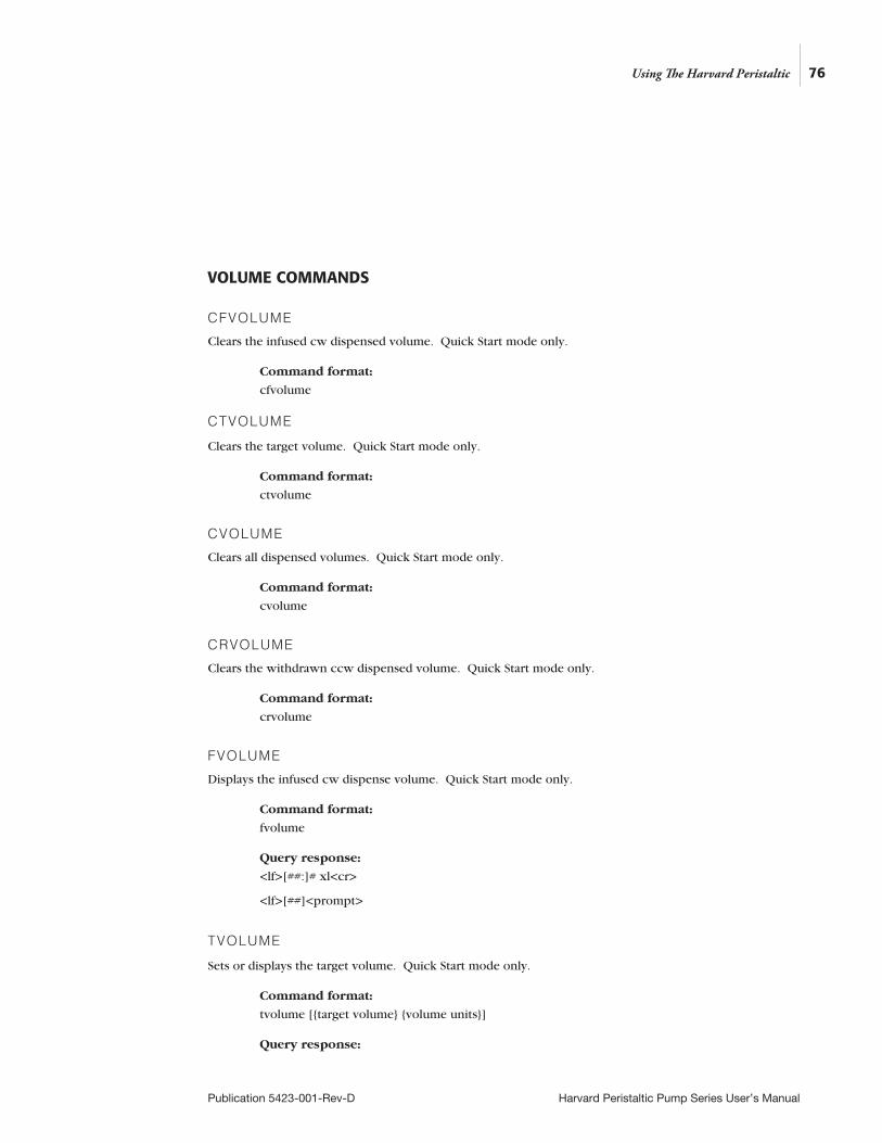
76
Publication 5423-001-Rev-D Harvard Peristaltic Pump Series User’s Manual
VOLUME COMMANDS
CFVOLUME
Clears the infused cw dispensed volume. Quick Start mode only.
Command format:
cfvolume CTVOLUME
Clears the target volume. Quick Start mode only.
Command format:
ctvolume
CVOLUME
Clears all dispensed volumes. Quick Start mode only.
Command format:
cvolume
CRVOLUME
Clears the withdrawn ccw dispensed volume. Quick Start mode only.
Command format:
crvolume
FVOLUME
Displays the infused cw dispense volume. Quick Start mode only.
Command format:
fvolume
Query response:
<lf>[##:]# xl<cr>
<lf>[##]<prompt>
TVOLUME
Sets or displays the target volume. Quick Start mode only.
Command format:
tvolume [target volume volume units]
Query response:
Using The Harvard Peristaltic
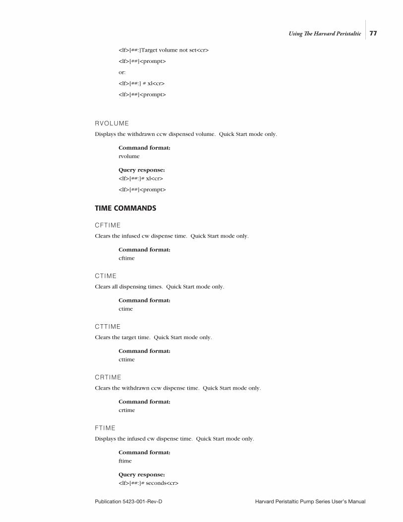
77
Publication 5423-001-Rev-D Harvard Peristaltic Pump Series User’s Manual
<lf>[##:]Target volume not set<cr>
<lf>[##]<prompt>
or:
<lf>[##:] # xl<cr>
<lf>[##]<prompt>
RVOLUME
Displays the withdrawn ccw dispensed volume. Quick Start mode only.
Command format:
rvolume
Query response:
<lf>[##:]# xl<cr>
<lf>[##]<prompt>
TIME COMMANDS
CFTIME
Clears the infused cw dispense time. Quick Start mode only.
Command format:
cftime
CTIME
Clears all dispensing times. Quick Start mode only.
Command format:
ctime
CTTIME
Clears the target time. Quick Start mode only.
Command format:
cttime
CRTIME
Clears the withdrawn ccw dispense time. Quick Start mode only.
Command format:
crtime
FTIME
Displays the infused cw dispense time. Quick Start mode only.
Command format:
ftime
Query response:
<lf>[##:]# seconds<cr>
Using The Harvard Peristaltic

78
Publication 5423-001-Rev-D Harvard Peristaltic Pump Series User’s Manual
<lf>[##]<prompt>
or:
<lf>[##:]##:##:##<cr>
<lf>[##]<prompt>
TTIME
Sets or displays the target time. Quick Start mode only.
Command format:
ttime [target time]
Query response:
<lf>[##:]Target time not set<cr>
<lf>[##]<prompt>
or:
<lf>[##:]# seconds<cr>
<lf>[##]<prompt>
or:
<lf>[##:]##:##:##<cr>
<lf>[##]<prompt>
RTIME
Displays the withdrawn ccw dispense time. Quick Start mode only.
Command format:
rtime
Query response:
<lf>[##:]# seconds<cr>
<lf>[##]<prompt>
or:
<lf>[##:]##:##:##<cr>
<lf>[##]<prompt>
DIGITAL I/O COMMANDS
INPUT
Reads and displays the trigger input port status.
Command format:
input
Query response:
<lf>[##:]Low.<cr>
Using The Harvard Peristaltic
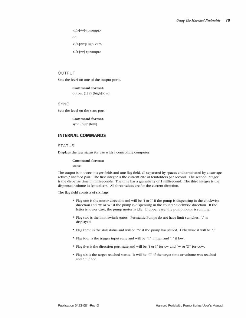
79
Publication 5423-001-Rev-D Harvard Peristaltic Pump Series User’s Manual
<lf>[##]<prompt>
or:
<lf>[##:]High.<cr>
<lf>[##]<prompt>
OUTPUT
Sets the level on one of the output ports.
Command format:
output 1|2 high|low
SYNC
Sets the level on the sync port.
Command format:
sync high|low
INTERNAL COMMANDS
STATUS
Displays the raw status for use with a controlling computer.
Command format:
status
The output is in three integer fields and one flag field, all separated by spaces and terminated by a carriage return / linefeed pair. The first integer is the current rate in femtoliters per second. The second integer is the dispense time in milliseconds. The time has a granularity of 1 millisecond. The third integer is the dispensed volume in femtoliters. All three values are for the current direction.
The flag field consists of six flags.
• Flag one is the motor direction and will be “i or I” if the pump is dispensing in the clockwise direction and “w or W” if the pump is dispensing in the counter-clockwise direction. If the letter is lower case, the pump motor is idle. If upper case, the pump motor is running.
• Flag two is the limit switch status. Peristaltic Pumps do not have limit switches, “.” is displayed.
• Flag three is the stall status and will be “S” if the pump has stalled. Otherwise it will be “.”.
• Flag four is the trigger input state and will be “T” if high and “.” if low.
• Flag five is the direction port state and will be “i or I” for cw and “w or W” for ccw.
• Flag six is the target reached status. It will be “T” if the target time or volume was reached and “.” if not.
Using The Harvard Peristaltic
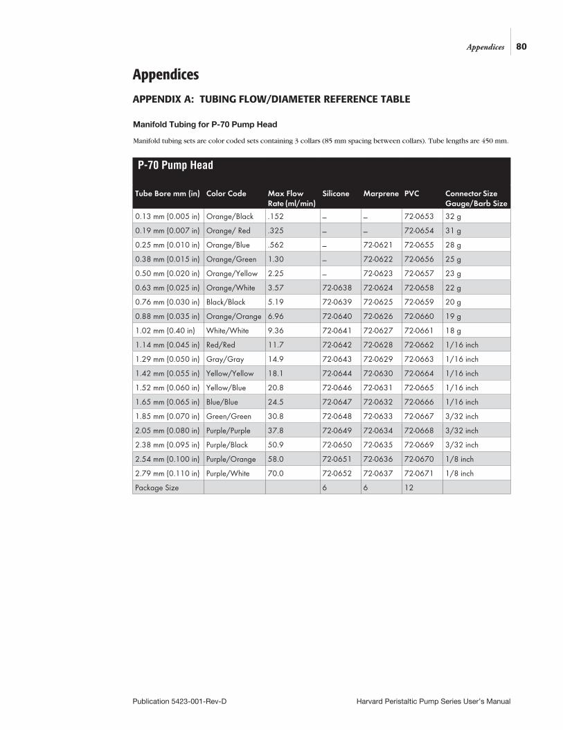
80Appendices
Publication 5423-001-Rev-D Harvard Peristaltic Pump Series User’s Manual
Appendices
APPENDIX A: TUBING FLOW/DIAMETER REFERENCE TABLE
P-70 Pump Head
Tube Bore mm (in) Color Code Max Flow Rate (ml/min)
Silicone Marprene PVC Connector Size Gauge/Barb Size
0.13 mm (0.005 in) Orange/Black .152 _ _ 72-0653 32 g
0.19 mm (0.007 in) Orange/ Red .325 _ _ 72-0654 31 g
0.25 mm (0.010 in) Orange/Blue .562 _ 72-0621 72-0655 28 g
0.38 mm (0.015 in) Orange/Green 1.30 _ 72-0622 72-0656 25 g
0.50 mm (0.020 in) Orange/Yellow 2.25 _ 72-0623 72-0657 23 g
0.63 mm (0.025 in) Orange/White 3.57 72-0638 72-0624 72-0658 22 g
0.76 mm (0.030 in) Black/Black 5.19 72-0639 72-0625 72-0659 20 g
0.88 mm (0.035 in) Orange/Orange 6.96 72-0640 72-0626 72-0660 19 g
1.02 mm (0.40 in) White/White 9.36 72-0641 72-0627 72-0661 18 g
1.14 mm (0.045 in) Red/Red 11.7 72-0642 72-0628 72-0662 1/16 inch
1.29 mm (0.050 in) Gray/Gray 14.9 72-0643 72-0629 72-0663 1/16 inch
1.42 mm (0.055 in) Yellow/Yellow 18.1 72-0644 72-0630 72-0664 1/16 inch
1.52 mm (0.060 in) Yellow/Blue 20.8 72-0646 72-0631 72-0665 1/16 inch
1.65 mm (0.065 in) Blue/Blue 24.5 72-0647 72-0632 72-0666 1/16 inch
1.85 mm (0.070 in) Green/Green 30.8 72-0648 72-0633 72-0667 3/32 inch
2.05 mm (0.080 in) Purple/Purple 37.8 72-0649 72-0634 72-0668 3/32 inch
2.38 mm (0.095 in) Purple/Black 50.9 72-0650 72-0635 72-0669 3/32 inch
2.54 mm (0.100 in) Purple/Orange 58.0 72-0651 72-0636 72-0670 1/8 inch
2.79 mm (0.110 in) Purple/White 70.0 72-0652 72-0637 72-0671 1/8 inch
Package Size 6 6 12
Manifold Tubing for P-70 Pump Head
Manifold tubing sets are color coded sets containing 3 collars (85 mm spacing between collars). Tube lengths are 450 mm.
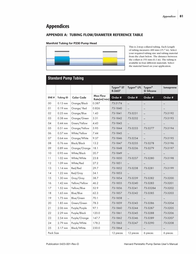
81
Publication 5423-001-Rev-D Harvard Peristaltic Pump Series User’s Manual
Appendices
Standard Pump Tubing
Tygon® ST R-3607
Tygon® LFL Tygon® SI Silicone 3350
Ismaprene
ENE # Tubing ID Color CodeMax Flow Rate(ml/min)
Order # Order # Order # Order #
00 0.13 mm Orange/Black 0.387 73-3174 _ _ _
01 0.19 mm Orange/ Red 0.826 73-1840 _ _ _
02 0.25 mm Orange/Blue 1.43 73-1841 73-3231 _ 73-3192
03 0.38 mm Orange/Green 3.31 73-1842 73-3232 _ 73-3193
04 0.44 mm Green/Yellow 4.43 73-1843 _ _ _
05 0.51 mm Orange/Yellow 5.95 73-1844 73-3233 73-3277 73-3194
06 0.57 mm White/Yellow 7.44 73-1845 _ _ _
07 0.64 mm Orange/White 9.37 73-1846 73-3234 _ 73-3195
08 0.76 mm Black/Black 13.2 73-1847 73-3235 73-3278 73-3196
09 0.89 mm Orange/Orange 18.1 73-1848 73-3236 73-3279 73-3197
10 0.95 mm White/Black 20.7 73-1849 _ _ _
11 1.02 mm White/White 23.8 73-1850 73-3237 73-3280 73-3198
12 1.09 mm White/Red 27.2 73-1851 _ _ _
13 1.14 mm Red/Red 29.7 73-1852 73-3238 73-3281 73-3199
14 1.22 mm Red/Gray 34.1 73-1853 _ _ _
15 1.30 mm Gray/Gray 38.7 73-1854 73-3239 73-3282 73-3200
16 1.42 mm Yellow/Yellow 46.2 73-1855 73-3240 73-3283 73-3201
17 1.52 mm Yellow/Blue 52.9 73-1856 73-3241 73-33284 73-3202
18 1.65 mm Blue/Blue 62.3 73-1857 73-3242 73-3285 73-3203
19 1.75 mm Blue/Green 70.1 73-1858 _ _ _
20 1.85 mm Green/Green 78.3 73-1859 73-3243 73-3286 73-3204
21 2.06 mm Purple/Purple 97.1 73-1860 73-3244 73-3287 73-3205
22 2.29 mm Purple/Black 120.0 73-1861 73-3245 73-3288 73-3206
23 2.54 mm Purple/Orange 147.7 73-1862 73-3246 73-3289 73-3207
24 2.79 mm Purple/White 178.2 73-1863 73-3247 73-3290 73-3208
25 3.17 mm Black/White 230.0 73-1864 _ _ _
Pack Size 12 pieces 12 pieces 6 pieces 6 pieces
Manifold Tubing for P230 Pump Head
Appendices
APPENDIX A: TUBING FLOW/DIAMETER REFERENCE TABLE
This is 2-stop collared tubing. Each Length of tubing measures 400 mm (15.7 in). Select your required tubing size and tubing material from the chart below. The distance between the collars is 153 mm (6.1 in). The tubing is available in four different materials. Select the material based on your application.
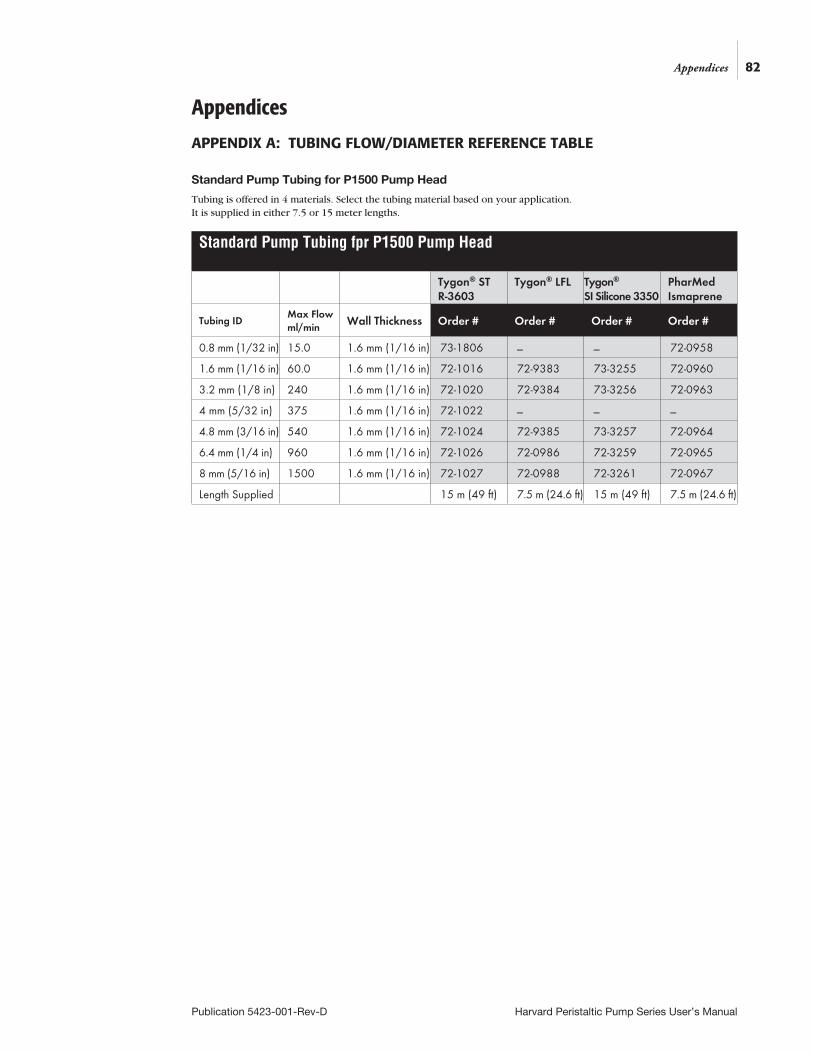
82
Publication 5423-001-Rev-D Harvard Peristaltic Pump Series User’s Manual
Appendices
APPENDIX A: TUBING FLOW/DIAMETER REFERENCE TABLE
Appendices
Standard Pump Tubing fpr P1500 Pump Head
Tygon® ST R-3603
Tygon® LFL Tygon® SI Silicone 3350
PharMed Ismaprene
Tubing IDMax Flow ml/min Wall Thickness Order # Order # Order # Order #
0.8 mm (1/32 in) 15.0 1.6 mm (1/16 in) 73-1806 _ _ 72-0958
1.6 mm (1/16 in) 60.0 1.6 mm (1/16 in) 72-1016 72-9383 73-3255 72-0960
3.2 mm (1/8 in) 240 1.6 mm (1/16 in) 72-1020 72-9384 73-3256 72-0963
4 mm (5/32 in) 375 1.6 mm (1/16 in) 72-1022 _ _ _
4.8 mm (3/16 in) 540 1.6 mm (1/16 in) 72-1024 72-9385 73-3257 72-0964
6.4 mm (1/4 in) 960 1.6 mm (1/16 in) 72-1026 72-0986 72-3259 72-0965
8 mm (5/16 in) 1500 1.6 mm (1/16 in) 72-1027 72-0988 72-3261 72-0967
Length Supplied 15 m (49 ft) 7.5 m (24.6 ft) 15 m (49 ft) 7.5 m (24.6 ft)
Standard Pump Tubing for P1500 Pump Head
Tubing is offered in 4 materials. Select the tubing material based on your application. It is supplied in either 7.5 or 15 meter lengths.
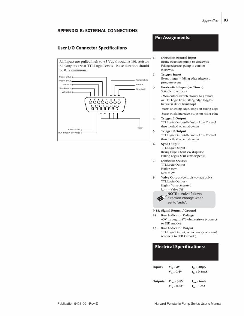
83
Publication 5423-001-Rev-D Harvard Peristaltic Pump Series User’s Manual
APPENDIX B: EXTERNAL CONNECTIONS
User I/O Connector Specifications
Appendices
All Inputs are pulled high to +5 Vdc through a 10k resistor All Outputs are at TTL Logic Levels. Pulse duration should be 0.1s minimum.
Trigger 1 Out
Trigger 2 Out
Sync Out
Direction Out
Valve Out
Footswitch In
Event In
Direction In
Run IndicatorRun Indicator or Voltage
Pin Assignments:
1. Direction control input Rising edge sets pump to clockwise Falling edge sets pump to counter-clockwise
2. Trigger Input Event trigger – falling edge triggers a program event
3. Footswitch Input (or Timer) Settable to work as:
- Momentary switch closure to ground or TTL Logic Low; falling edge toggles between states (run/stop)
-Starts on rising edge, stops on falling edge
-Starts on falling edge, stops on rising edge
4. Trigger 1 Output TTL Logic Output-Default = Low Control thru method or serial comm
5. Trigger 2 Output TTL Logic Output-Default = Low Control thru method or serial comm
6. Sync Output TTL Logic Output – Rising Edge = Start cw dispense Falling Edge= Start ccw dispense
7. Direction Output TTL Logic Output – High = ccw Low = cw
8. Valve Output (controls voltage only) TTL Logic Output – High = Valve Actuated Low = Valve Off
9-13. Signal Return / Ground
14. Run Indicator Voltage +5V through a 470 ohm resistor (connect to LED Anode)
15. Run Indicator Output TTL Logic Output, active low (low = run) (connect to LED Cathode)
Electrical Specifications:
Inputs: VIH ≥ 2V IIH ≤ 20µA
VIL ≤ 0.4V IIL ≤ 0.5mA
Outputs: VOH ≥ 3.8V IOH ≤ 6mA
VOL ≤ 0.4V IOL ≤ 6mA
NOTE: Valve follows direction change when set to ‘auto’.
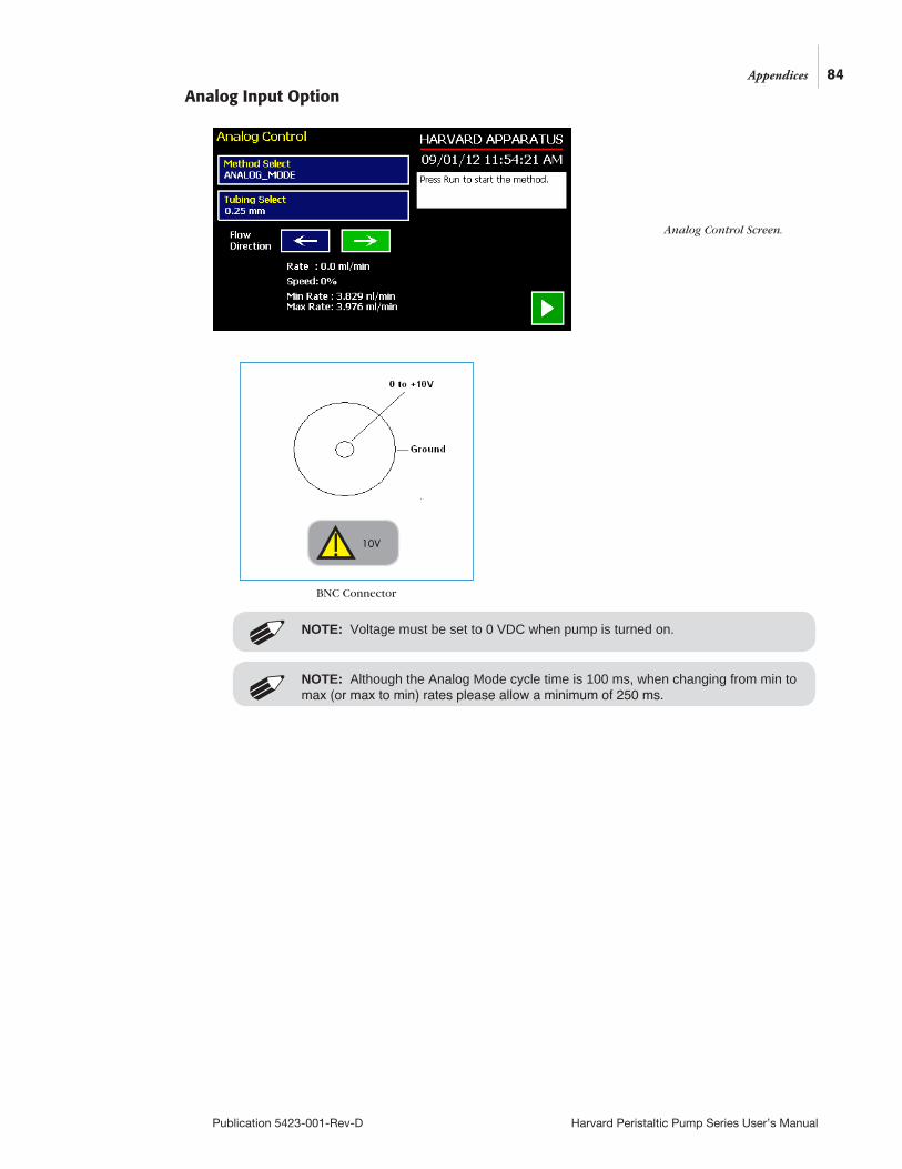
84
Publication 5423-001-Rev-D Harvard Peristaltic Pump Series User’s Manual
Analog Input Option
Appendices
Analog Control Screen.
NOTE: Although the Analog Mode cycle time is 100 ms, when changing from min to max (or max to min) rates please allow a minimum of 250 ms.
NOTE: Voltage must be set to 0 VDC when pump is turned on.
10V
BNC Connector
!
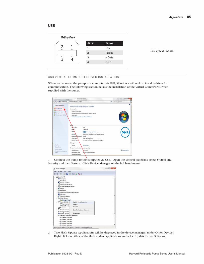
85
Publication 5423-001-Rev-D Harvard Peristaltic Pump Series User’s Manual
USB
USB VIRTUAL COMMPORT DRIVER INSTALLATION
When you connect the pump to a computer via USB, Windows will seek to install a driver for communication. The following section details the installation of the Virtual CommPort Driver supplied with the pump.
1. Connect the pump to the computer via USB. Open the control panel and select System and Security and then System. Click Device Manager on the left hand menu.
2. Two Flash Update Applications will be displayed in the device manager, under Other Devices. Right click on either of the flash update applications and select Update Driver Software.
Appendices
USB Type B Female.
Mating Face
Pin # Signal
1 +5V2 - Data3 + Data4 GND
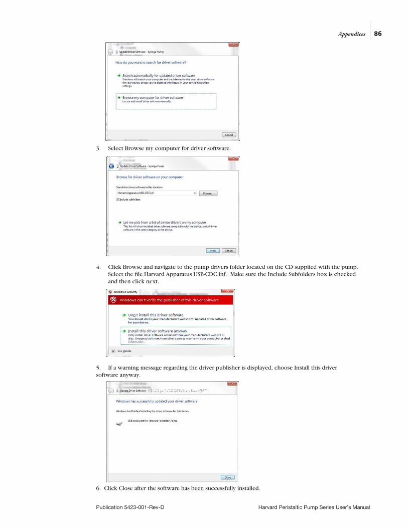
86
Publication 5423-001-Rev-D Harvard Peristaltic Pump Series User’s Manual
3. Select Browse my computer for driver software.
4. Click Browse and navigate to the pump drivers folder located on the CD supplied with the pump. Select the file Harvard Apparatus USB-CDC.inf. Make sure the Include Subfolders box is checked and then click next.
5. If a warning message regarding the driver publisher is displayed, choose Install this driver software anyway.
6. Click Close after the software has been successfully installed.
Appendices
USB serial port for Harvard Peristaltic Pump (COM7)
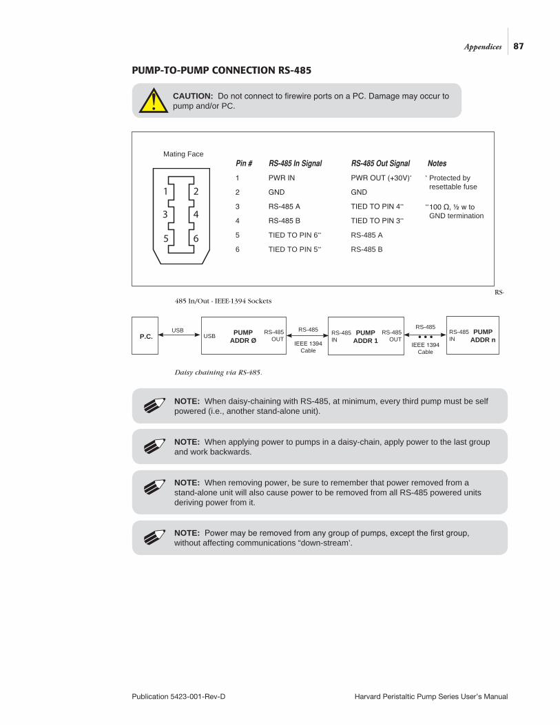
87
Publication 5423-001-Rev-D Harvard Peristaltic Pump Series User’s Manual
PUMP-TO-PUMP CONNECTION RS-485
RS- 485 In/Out - IEEE-1394 Sockets
Daisy chaining via RS-485.
NOTE: Power may be removed from any group of pumps, except the first group, without affecting communications “down-stream’.
NOTE: When removing power, be sure to remember that power removed from a stand-alone unit will also cause power to be removed from all RS-485 powered units deriving power from it.
NOTE: When applying power to pumps in a daisy-chain, apply power to the last group and work backwards.
NOTE: When daisy-chaining with RS-485, at minimum, every third pump must be self powered (i.e., another stand-alone unit).
P.C. PUMP ADDR Ø
USBUSB RS-485
OUTPUMP
ADDR 1RS-485
OUTRS-485 IN
PUMP ADDR n
RS-485 IN
RS-485
IEEE 1394 Cable
RS-485
• • •IEEE 1394
Cable
1 2
3 4
5 6
Pin # RS-485 In Signal RS-485 Out Signal Notes
1 PWR IN PWR OUT (+30V)*
2 GND GND
3 RS-485 A TIED TO PIN 4**
4 RS-485 B TIED TO PIN 3**
5 TIED TO PIN 6** RS-485 A
6 TIED TO PIN 5** RS-485 B
Mating Face
* Protected by resettable fuse
** 100 Ω, ½ w to GND termination
CAUTION: Do not connect to firewire ports on a PC. Damage may occur to pump and/or PC.
Appendices
!

Setting the Address on the Control Box / Master UnitThe address of the master unit must always be set to 0 (zero).
1. On the pump’s touchscreen go to the Settings menu
2. Press the ‘Address button
3. Set the Pump Address to 0 (for Master) or 1-99 for other pumps in the chain
4. Press ‘Accept’
88
Publication 5423-001-Rev-D Harvard Peristaltic Pump Series User’s Manual
Appendices
Settings screen showing the ‘Address button’
Set Pump Address screen
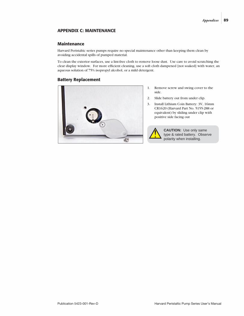
89
Publication 5423-001-Rev-D Harvard Peristaltic Pump Series User’s Manual
APPENDIX C: MAINTENANCE
MaintenanceHarvard Peristaltic series pumps require no special maintenance other than keeping them clean by avoiding accidental spills of pumped material.
To clean the exterior surfaces, use a lint-free cloth to remove loose dust. Use care to avoid scratching the clear display window. For more efficient cleaning, use a soft cloth dampened [not soaked] with water, an aqueous solution of 75% isopropyl alcohol, or a mild detergent.
Battery Replacement
1. Remove screw and swing cover to the side.
2. Slide battery out from under clip.
3. Install Lithium Coin Battery: 3V, 16mm CR1620 (Harvard Part No. 5155-288 or equivalent) by sliding under clip with positive side facing out
CAUTION: Use only same type & rated battery. Observe polarity when installing.
Appendices
!
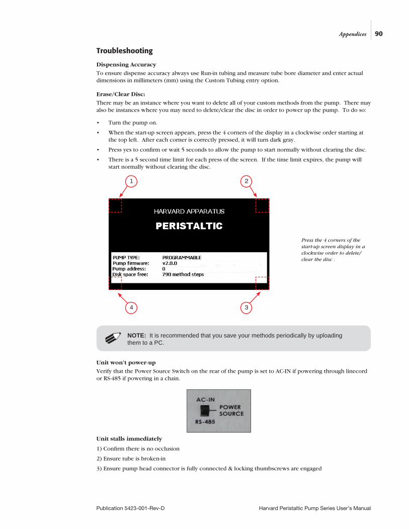
90
Publication 5423-001-Rev-D Harvard Peristaltic Pump Series User’s Manual
Appendices
Troubleshooting
Dispensing Accuracy
To ensure dispense accuracy always use Run-in tubing and measure tube bore diameter and enter actual dimensions in millimeters (mm) using the Custom Tubing entry option.
Erase/Clear Disc:
There may be an instance where you want to delete all of your custom methods from the pump. There may also be instances where you may need to delete/clear the disc in order to power up the pump. To do so:
• Turn the pump on.
• When the start-up screen appears, press the 4 corners of the display in a clockwise order starting at the top left. After each corner is correctly pressed, it will turn dark gray.
• Press yes to confirm or wait 5 seconds to allow the pump to start normally without clearing the disc.
• There is a 5 second time limit for each press of the screen. If the time limit expires, the pump will start normally without clearing the disc.
Unit won’t power-up
Verify that the Power Source Switch on the rear of the pump is set to AC-IN if powering through linecord or RS-485 if powering in a chain.
Unit stalls immediately
1) Confirm there is no occlusion
2) Ensure tube is broken-in
3) Ensure pump head connector is fully connected & locking thumbscrews are engaged
NOTE: It is recommended that you save your methods periodically by uploading them to a PC.
2
3
1
4
Press the 4 corners of the start-up screen display in a clockwise order to delete/clear the disc .
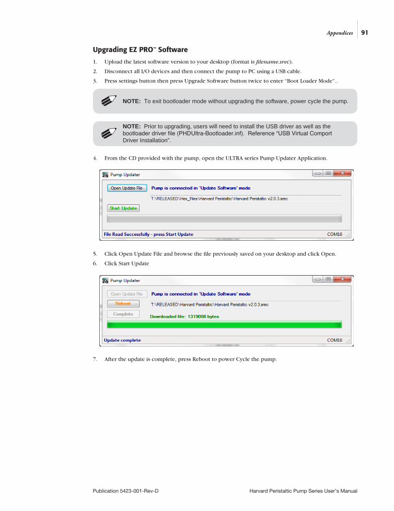
91
Publication 5423-001-Rev-D Harvard Peristaltic Pump Series User’s Manual
Appendices
Upgrading EZ PRO™ Software
1. Upload the latest software version to your desktop (format is filename.srec).
2. Disconnect all I/O devices and then connect the pump to PC using a USB cable.
3. Press settings button then press Upgrade Software button twice to enter “Boot Loader Mode”..
4. From the CD provided with the pump, open the ULTRA series Pump Updater Application.
5. Click Open Update File and browse the file previously saved on your desktop and click Open.
6. Click Start Update
7. After the update is complete, press Reboot to power Cycle the pump.
NOTE: Prior to upgrading, users will need to install the USB driver as well as the bootloader driver file (PHDUltra-Bootloader.inf). Reference “USB Virtual Comport Driver Installation”.
NOTE: To exit bootloader mode without upgrading the software, power cycle the pump.
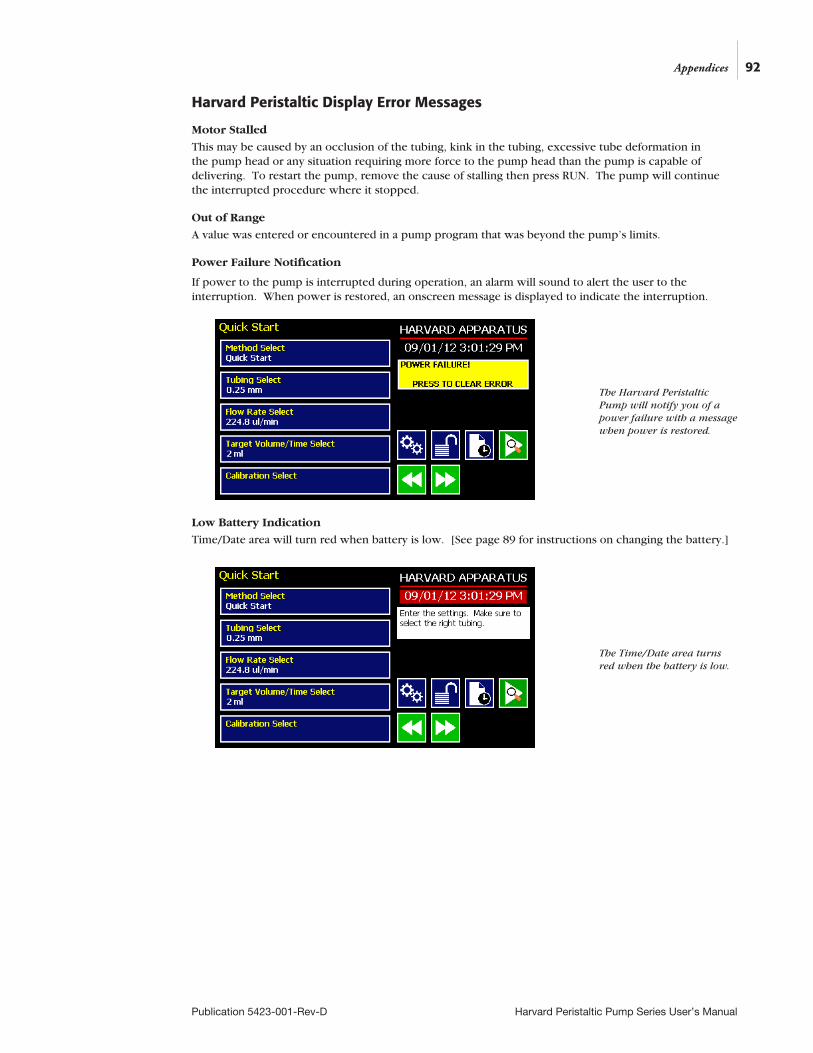
92
Publication 5423-001-Rev-D Harvard Peristaltic Pump Series User’s Manual
Appendices
Harvard Peristaltic Display Error Messages
Motor Stalled
This may be caused by an occlusion of the tubing, kink in the tubing, excessive tube deformation in the pump head or any situation requiring more force to the pump head than the pump is capable of delivering. To restart the pump, remove the cause of stalling then press RUN. The pump will continue the interrupted procedure where it stopped.
Out of Range
A value was entered or encountered in a pump program that was beyond the pump’s limits.
Power Failure Notification
If power to the pump is interrupted during operation, an alarm will sound to alert the user to the interruption. When power is restored, an onscreen message is displayed to indicate the interruption.
Low Battery Indication
Time/Date area will turn red when battery is low. [See page 89 for instructions on changing the battery.]
The Harvard Peristaltic Pump will notify you of a power failure with a message when power is restored.
The Time/Date area turns red when the battery is low.
93
Publication 5423-001-Rev-D Harvard Peristaltic Pump Series User’s Manual
Appendices
APPENDIX D: ORDERING INFORMATION
Standard Version
Description P-70 P-230 P-1500
Harvard Peristaltic Pump with Pump Head 70-7000 70-7001 70-7002
Pump Head only 70-7003 70-7004 70-7005
Accessories
Catalog # Description
70-4000 RS-485 Cable for Pump-to-Pump Communication, 0.5 m
70-4021 RS-485 Cable for Pump-to-Pump Communication, 1 m
70-4001 RS-485 Cable for Pump-to-Pump Communication, 2 m
70-4020 RS-485 Cable for Pump-to-Pump Communication, 30 ft
70-4002 USB Cable for PC-to-Pump Communication, 2 m
70-4003 USB Cable for PC-to-Pump Communication, 5 m
5113-001 Line Cord, US (115 v)
70-3039 Cable for Analog Control Option (BNC with flying leads)
70-4006 Adapter, D-sub 15 to Term. Blk
70-2215 Footswitch (w/ Phono Plug)
55-7010 Auto Fill Valve Box, Low Pressure
55-7012 Auto Fill Valve Box, Medium Pressure
55-7008 Auto Fill Valve Box, High Pressure
55-7009 Continuous Delivery Valve Box, Low Pressure
55-7013 Continuous Delivery Valve Box, Medium Pressure
55-7007 Continuous Delivery Valve Box, High Pressure
For tubing, see Appendix A.
For additional items, please visit our website www.harvardapparatus.com or call (800) 272-2775.
Declaration of Conformity
Beth Bauman
VP Engineering / Operations
(Signature)
(Full Name)
(Position)
Manufacturer: Harvard Apparatus, Inc. 84 October Hill Road Holliston, Massachusetts 01746-1388, U.S.A. Phone: (508) 893-8999
We herewith declare that the following product:
Product Name: Harvard Peristaltic Pump SeriesModel No.: Harvard Peristaltic - Catalog # 70-7xxx
To which this declaration relates, is in conformity with the applicable EC Directives,
harmonized standards, and other normative requirements:
Application of Council Directive(s): 2006/95/EC Low Voltage Directive 2004/108/EC Electromagnetic Compatibility Directive 2011/65/EU RoHS DirectiveStandard(s) to which conformity is declared:
Safety: EN 61010-1:2012 (3rd Edition)
Emmissions/Immunity: IEC 61326-1:2005, Ed.1 IEC 61000-4-2 IEC 61000-4-3:2002 IEC 61000-4-4:2004 IEC 61000-4-5:2001 IEC 61000-4-6:2003 IEC 61000-4-8:1993 IEC 61000-4-11:2004 IEC 61000-3-2:2000 IEC 61000-3-3:2002 CISPR11:2003+A1:2004, Group 1, Class B
EMC and Safety compliance were evaluated by Intertek/ETL Semko
Reference test report file numbers: 100898583 BOX-001A, -002, -003
I, the undersigned, hereby declare that the equipment specified above conforms to the above Directive(s) and Standard(s).
Place: United States of AmericaDate: October 10, 2012