HARTZELL PROPELLER INC. One Propeller Place Piqua, Ohio...
22
MANUAL REVISION TRANSMITTAL MANUAL 173 (61-10-73) Composite Spinner Field Maintenance and Minor Repair Manual REVISION 1 dated December 2014 Attached is a copy of Revision 1 to Hartzell Propeller Inc. Manual 173 Page Control Chart for Revision 1: Remove Insert Chapter/Page No. Chapter/Page No. COVER COVER Cover and Inside Cover Cover and Inside Cover REVISION HIGHLIGHTS REVISION HIGHLIGHTS pages 1 and 2 pages 1 and 2 LIST OF EFFECTIVE PAGES LIST OF EFFECTIVE PAGES pages 1 and 2 pages 1 and 2 MINOR REPAIR MINOR REPAIR pages 2-3 and 2-4 pages 2-3 and 2-4 pages 2-4.1 and 2-4.2 pages 2-5 and 2-6 pages 2-5 and 2-6 pages 2-25 and 2-26 pages 2-25 and 2-26 FINISH PROCEDURES FINISH PROCEDURES pages 3-11 and 3-12 pages 3-11 and 3-12 pages 3-29 thru 3-32 pages 3-29 thru 3-32 NOTE 1: When the manual revision has been inserted in the manual, record the information required on the Record of Revisions pages in this manual. NOTE 2: Pages distributed in this revision may include pages from previous revisions if they are on the opposite side of revised pages. This is done as a convenience to those users who wish to print a two-sided copy of the new revision. HARTZELL PROPELLER INC. One Propeller Place Piqua, Ohio 45356-2634 U.S.A. Telephone: 937.778.4200 Fax: 937.778.4391 This page may be discarded after the revision has been inserted in the manual.
Transcript of HARTZELL PROPELLER INC. One Propeller Place Piqua, Ohio...

MANUAL REVISION TRANSMITTALMANUAL 173 (61-10-73)
Composite Spinner Field Maintenance and Minor Repair ManualREVISION 1 dated December 2014
Attached is a copy of Revision 1 to Hartzell Propeller Inc. Manual 173 Page Control Chart for Revision 1:Remove Insert Chapter/Page No. Chapter/Page No.COVER COVER Cover and Inside Cover Cover and Inside Cover
REVISION HIGHLIGHTS REVISION HIGHLIGHTS pages 1 and 2 pages 1 and 2
LIST OF EFFECTIVE PAGES LIST OF EFFECTIVE PAGES pages 1 and 2 pages 1 and 2
MINOR REPAIR MINOR REPAIR pages 2-3 and 2-4 pages 2-3 and 2-4 pages 2-4.1 and 2-4.2 pages 2-5 and 2-6 pages 2-5 and 2-6 pages 2-25 and 2-26 pages 2-25 and 2-26
FINISH PROCEDURES FINISH PROCEDURES pages 3-11 and 3-12 pages 3-11 and 3-12 pages 3-29 thru 3-32 pages 3-29 thru 3-32
NOTE 1: When the manual revision has been inserted in the manual, record the information required on the Record of Revisions pages in this manual.
NOTE 2: Pages distributed in this revision may include pages from previous revisions if they are on the opposite side of revised pages. This is done as a convenience to those users who wish to print a two-sided copy of the new revision.
HARTZELL PROPELLER INC.One Propeller PlacePiqua, Ohio 45356-2634 U.S.A.Telephone: 937.778.4200Fax: 937.778.4391
This page may be discarded after the revision has been inserted in the manual.

(This page is intentionally blank.)

Hartzell Propeller Inc.One Propeller PlacePiqua, Ohio 45356-2634 U.S.A.Phone: 937.778.4200Fax: 937.778.4391
Manual No. 17361-10-73Revision 1December 2014
Composite Spinner Field Maintenance and Minor Repair Manual
Composite Spinner Assemblies
D-5253D-5311-( )D-5362E-5579-6D-7409-( )E-7480101298 (hybrid)102870103409 (hybrid)103585 (hybrid)103629 (hybrid)104529104888 (hybrid)105085105127105656 (hybrid)105675 (hybrid)105945 (hybrid)

Inside Cover Rev. 1 Dec/1461-16-73COVER
COMPOSITE SPINNER FIELD MAINTENANCE AND MINOR REPAIR MANUAL
173
© 1997, 2004, 2007, 2008, 2010, 2013, 2014 - Hartzell Propeller Inc. - All rights reserved

COMPOSITE SPINNER FIELD MAINTENANCE AND MINOR REPAIR MANUAL
173
Page 1 Rev. 1 Dec/14
61-10-73REVISION HIGHLIGHTS
REVISION HIGHLIGHTS
Revision 1, dated December 2014, incorporates the following:
• COVER
• Revisedtomatchthemanualrevision
• REVISION HIGHLIGHTS
• Revisedtomatchthemanualrevision
• LISTOFEFFECTIVEPAGES
• Revisedtomatchthemanualrevision
• MINORREPAIR
• RevisedTable2-1,"SpinnerRepairMaterials" • RevisedTable2-2,"NutplatesandRivetsThatCanBeReplaced"
• FINISHPROCEDURES
• RevisedTable3-1,"FinishProcedures" • RevisedFigure3-1,"ResistanceCheckoftheDome" • RevisedFigure3-2,"ResistanceCheckoftheBulkhead"

COMPOSITE SPINNER FIELD MAINTENANCE AND MINOR REPAIR MANUAL
173
Page 2 Rev. 1 Dec/14
61-10-73REVISION HIGHLIGHTS
REVISION HIGHLIGHTS
1. Introduction
A. General
(1) Thisisalistofcurrentrevisionsthathavebeenissuedagainstthismanual.PleasecomparetoRECORDOFREVISIONSpagetoensurethatallrevisionshavebeenaddedtothemanual.
B. Components
(1) RevisionNo.indicatestherevisionsincorporatedinthismanual.
(2) IssueDateisthedateofrevision.
(3) Commentsindicatestheleveloftherevision.
(a) NewIssueisanewmanualdistribution.Themanualisdistributedinitsentirety.Alltherevisiondatesarethesameandnochangebarsareused.
(b) Reissueisarevisiontoanexistingmanualthatincludesmajorcontentand/ormajorformatchanges.Themanualisdistributedinitsentirety.Alltherevisiondatesarethesameandnochangebarsareused.
(c) MajorRevisionisarevisiontoanexistingmanualthatincludesmajorcontentorminorformatchangesoveralargeportionofthemanual.Themanualisdistributedinitsentirety.Alltherevisiondatesarethesame,butchangebarsareusedtoindicatethechangesincorporatedinthelatestrevisionofthemanual.
(d) MinorRevisionisarevisiontoanexistingmanualthatincludesminorcontentchangestothemanual.Onlytherevisedpagesofthemanualaredistributed.Eachpageretainsthedateandthechangebarsassociatedwith the last revision to that page.
Revision No. IssueDate Comments
Original Sep/14 NewIssue Rev.1 Dec/14 MinorRevision

Page 1 Rev. 1 Dec/14
LIST OF EFFECTIVE PAGES 61-10-73
LIST OF EFFECTIVE PAGES
Chapter Page Rev. Level Date
COMPOSITE SPINNER FIELD MAINTENANCE AND MINOR REPAIR MANUAL
173
Cover/Cover Back Cover/Cover Back Rev. 1 Dec/14Revision Highlights 1 and 2 Rev. 1 Dec/14Record of Revisions 1 and 2 Original Sep/14Record of Temporary Revisions 1 and 2 Original Sep/14Service Document List 1 and 2 Original Sep/14Airworthiness Limitations 1 and 2 Original Sep/14List of Effective Pages 1 and 2 Rev. 1 Dec/14Table of Contents 1 and 2 Original Sep/14Introduction 1 thru 14 Original Sep/14Repair Limits 1-1 thru 1-18 Original Sep/14Minor Repair 2-1 thru 2-3 Original Sep/14Minor Repair 2-4 Rev. 1 Dec/14Minor Repair 2-4.1 and 2-4.2 Rev. 1 Dec/14Minor Repair 2-5 Rev. 1 Dec/14Minor Repair 2-6 thru 2-24 Original Sep/14Minor Repair 2-25 Rev. 1 Dec/14Minor Repair 2-26 thru 2-32 Original Sep/14Finish Procedures 3-1- thru 3-10 Original Sep/14Finish Procedures 3-11 and 3-12 Rev. 1 Dec/14Finish Procedures 3-13 thru 3-29 Original Sep/14Finish Procedures 3-30 Rev. 1 Dec/14Finish Procedures 3-31 Original Sep/14Finish Procedures 3-32 Rev. 1 Dec/14Finish Procedures 3-33 thru 36 Original Sep/14Tooling 4-1 thru 4-4 Original Sep/14

Page 2 Rev. 1 Dec/14
LIST OF EFFECTIVE PAGES 61-10-73
COMPOSITE SPINNER FIELD MAINTENANCE AND MINOR REPAIR MANUAL
173
(This page is intentionally blank.)

Page 2-3 MINOR REPAIR 61-10-73 Sep/14
COMPOSITE SPINNER FIELD MAINTENANCE AND MINOR REPAIR MANUAL
173
1. General
A. Fordefinitionsandpersonnelrequirements,refertotheIntroductionchapterofthismanual.
2. Dome
A. NoseErosion
(1) Thisrepairmaybeperformedonerosionofthecompositematerialatthedomenoseofnotmorethanonelayer.
(a) Forcuredplythicknessofthematerial,refertoTable2-1SpinnerRepair Materials.
(b) Ifthedamageismorethanonelayer,contactHartzellPropellerInc.forevaluation.
(c) Thisrepairdoesapplytotherepairofthedomeerosionshield.ForrepairofthedomeerosionshieldrefertotheDomeErosionShieldRepairsectioninthischapter.
(2) Usingagrinderorsanderwith140gritorfinersandpaper,removethepaintfromaroundthedamagedareatoproduceasmoothtransitionfromthedamagedareatothedomesurface.
WARNING: ADHESIVESANDSOLVENTSAREFLAMMABLEANDTOXICTOTHESKIN,EYES,ANDRESPIRATORYTRACT.SKINANDEYEPROTECTIONAREREQUIRED.AVOIDPROLONGEDCONTACTANDBREATHINGOFVAPORS.USESOLVENTRESISTANTGLOVESTOMINIMIZESKINCONTACTANDWEARSAFETYGLASSESFOREYEPROTECTION.USEINAWELLVENTILATEDAREAAWAYFROMSPARKSANDFLAME.READANDOBSERVEALLWARNINGLABELS.
(3) UsingcleancheeseclothCM159orequivalentdampenedwithsolvent acetoneCM173,MEKCM106,orMPKCM219,cleanthearea.
(4) PermitthesolventacetoneCM173,MEKCM106,orMPKCM219toevaporate.
(5) UsingadhesiveCM14orCM15,laminateenoughfiberglassfabricCM42orCM55tothedamagedareatoachievetheoriginalshape.
(6) Permittheadhesivetocureinaccordancewithstep2.A.(6)(a)or step2.A.(6)(b).
(a) For12hoursatroomtemperatureabove70°F(21.1°C)
(b) Foraminimumof2hoursat130°to145°F(55to62°C)
(7) Sandtherepairedareatotheoriginalshape.

Page 2-4 MINOR REPAIR 61-10-73 Rev.1Dec/14
COMPOSITE SPINNER FIELD MAINTENANCE AND MINOR REPAIR MANUAL
173
Spinner Repair Materials Table 2-1
Spinner Assembly
PartNumber
Dome Unit
PartNumber
MainBulkhead/AdapterRingPartNumber
Construction Repair Material
Cured Ply
ThicknessD-5253
D-5263 Carbon CM111 0.0190inch (0.215mm)
D-5264 Carbon CM111 0.0190inch (0.215mm)
D-5311-()
D-5312-() Carbon CM111 0.0190inch (0.215mm)
D-5313-() Carbon CM111 0.0190inch (0.215mm)
D-5362
D-5363 Carbon CM111 0.0190inch (0.215mm)
D-5364 Carbon CM111 0.0190inch (0.215mm)
E-5579-6
E-5580-4 Carbon CM111 0.0190inch (0.215mm)
E-5581 Carbon CM111 0.0190inch (0.215mm)
D-7409-()
D-7408-() Carbon CM111 0.0190inch (0.215mm)
D-7404-() Carbon CM111 0.0190inch (0.215mm)
E-7480
E-7481 Carbon CM111 0.0190inch (0.215mm)
D-6666 Carbon CM111 0.0190inch (0.215mm)
101298
101299 Carbon CM111 0.0190inch (0.215mm)
D-7084-1G Metal --- ---102870
102885 Carbon/ Fiberglass CM55 0.085inch
0.215mm)
102892 Carbon/ Fiberglass CM55 0.085inch
0.215mm)

Page 2-4.1 MINOR REPAIR 61-10-73 Rev.1Dec/14
COMPOSITE SPINNER FIELD MAINTENANCE AND MINOR REPAIR MANUAL
173
Spinner Repair Materials Table 2-1, continued
103409
103410 Fiberglass CM55 0.085inch 0.215mm)
C-2472-6P Metal --- ---103585
103582 Fiberglass CM55 0.085inch 0.215mm)
103584 AdapterRingUnit Metal --- ---
103629
103627 Fiberglass CM55 0.085inch 0.215mm)
103628() AdapterRingUnit Metal --- ---
104529
104573 Carbon/ Fiberglass CM55 0.085inch
0.215mm)104572
MainBulkheadCarbon/ Fiberglass CM55 0.085inch
0.215mm)104571
FairingUnit (DoesNotInclude
theTab)
Carbon/ Fiberglass CM55 0.085inch
0.215mm)
104888
104886 Fiberglass CM55 0.085inch 0.215mm)
104887 Metal --- ---105085
105122 Carbon/ Fiberglass CM55 0.085inch
0.215mm)
105123 Carbon/ Fiberglass --- ---
105127
105129 Carbon/ Fiberglass CM55 0.085inch
0.215mm)
105307 Carbon/ Fiberglass CM55 0.085inch
0.215mm)105656
105651 Carbon/ Fiberglass CM55 0.085inch
0.215mm)105652 Metal --- ---
Spinner Assembly
PartNumber
Dome Unit
PartNumber
MainBulkhead/AdapterRing/ FairingUnitPartNumber
Construction Repair Material
Cured Ply
Thickness

Page 2-4.2 MINOR REPAIR 61-10-73 Rev.1Dec/14
COMPOSITE SPINNER FIELD MAINTENANCE AND MINOR REPAIR MANUAL
173
Spinner Assembly
PartNumber
Dome Unit
PartNumber
MainBulkhead/AdapterRing/ FairingUnitPartNumber
Construction Repair Material
Cured Ply
Thickness
105675
105674 Fiberglass CM55 0.085inch 0.215mm)
105672 Metal --- ---105945
105943 Fiberglass CM55 0.085inch 0.215mm)
105944 Metal --- ---
Spinner Repair Materials Table 2-1, continued

Page2-5 MINOR REPAIR 61-10-73 Rev.1Dec/14
COMPOSITE SPINNER FIELD MAINTENANCE AND MINOR REPAIR MANUAL
173
(Thispageisintentionallyblank.)

Page2-6 MINOR REPAIR 61-10-73 Sep/14
COMPOSITE SPINNER FIELD MAINTENANCE AND MINOR REPAIR MANUAL
173
Minor Repair Limits of Crushed or Missing Material for the Dome OD TrimlineFigure 2-1
APS1021B
HalftheDistancetoHoleCenterline
DistancetoHoleCenterline
Taperof0.25inch(6.4mm)minimum
CrushedorMissingMaterial
Crack
Taperof0.25inch(6.4mm)minimum

Page2-25 MINOR REPAIR 61-10-73 Rev.1Dec/14
COMPOSITE SPINNER FIELD MAINTENANCE AND MINOR REPAIR MANUAL
173
Spinner Assembly
Bulkhead/AdapterRing
FillerPlate
HoopUnit
Nutplate Type Rivet
103629 103628() B-3846-3 B-3849-3
Fixed Floating B-3847-4
104529() 104572 B-3849-3 Floating B-3878-3-4
104888() 104887 B-3846-3 B-3849-3
Fixed Floating B-3847-5
105085() 105123() B-3849-3 Floating B-3878-3-4
105127() 105307 B-3846-3 B-3849-3
Fixed Floating B-3847-4
105656() 105652() B-3846-3 B-3849-3
Fixed Floating B-3847-5
105945 105944 B-3846-3 B-3849-3
Fixed Floating B-3847-4
Nutplates and Rivets That Can Be ReplacedTable 2-2, page 2 of 2

Page2-26 MINOR REPAIR 61-10-73 Sep/14
COMPOSITE SPINNER FIELD MAINTENANCE AND MINOR REPAIR MANUAL
173
G.ReplacingaNutplateonaCompositeBulkhead
(1) NutplateRemoval,Method1
WARNING: SOLVENTSAREFLAMMABLEANDTOXICTOTHESKIN,EYES,ANDRESPIRATORYTRACT.SKINANDEYEPROTECTIONAREREQUIRED.AVOIDPROLONGEDCONTACTANDBREATHINGOFVAPORS.USESOLVENTRESISTANTGLOVESTOMINIMIZESKINCONTACTANDWEARSAFETYGLASSESFOREYEPROTECTION.USEINAWELLVENTILATEDAREAAWAYFROMSPARKSANDFLAME.READANDOBSERVEALLWARNINGLABELS.
(a) UsingsolventacetoneCM173,MEKCM106,orMPKCM219,thoroughlycleanalloilandgreasefrombothsidesofthebulkhead,aroundthenutplatetoberemoved.
(b) Applymaskingmaterial(aluminumfoiltape)totheareaaroundthenutplatetoavoiddamagingthecompositematerialduringgrinding.
CAUTION1: USEEXTREMECAUTIONWHENGRINDINGTHERIVETSHANKSTOAVOIDDAMAGETOTHECOMPOSITEBULKHEAD.ADAMAGEDBULKHEADMUSTBERETURNEDTOHARTZELLPROPELLERINC.
CAUTION2: DONOTOVERHEATTHECOMPOSITEMATERIALDURINGGRINDINGOFTHERIVETHEADS.IFNECESSARY,USEWATERTOCOOLTHENUTPLATEDURINGGRINDING.
(c) Usingasmallhand-grinder,removetheheadoftherivetsthatholdthenutplateinplaceonthebulkhead.
CAUTION: USEEXTREMECAUTIONWHENREMOVINGTHENUTPLATESTOAVOIDPULLINGTHERIVETHEADSTHROUGHTHEBULKHEAD.ADAMAGEDBULKHEADMUSTBERETURNEDTOHARTZELLPROPELLERINC.
(d) Removethenutplatefromthebulkheadbylightlypullingwithpliers.
1 Ifthenutplatecannotberemoved,usethegrindertoremovemorematerialfromthenutplateandrivetsuntilthenutplatecanberemoved.
(e) Removetherivetsfromthebulkhead.
1 Ifnecessary,removetherivetheadsfromthebacksideofthebulkheadbyusingasmallpinpunch.
(f) Removethemaskingmaterial(aluminumfoiltape).
(g) UsingacetoneCM173,MEKCM106,orMPKCM219,cleantheholeandtheareaaroundthehole.

Finish Procedures Table 3-1, Continued
Finish Sequence
Finish Procedure
SpinnerAssembly 105085
SpinnerAssembly 105127
SpinnerAssembly 105656
Dome 105122
Bulkhead 105123
Dome 105129
Bulkhead 105307
Dome 105651
Bulkhead 105652
1 Masking --- --- --- --- --- ---
2 Primer Filler X X X X X ---
3
Minor Blemish
Correction See NOTE 1
X X X X X ---
4 Primer Sealer X X X X X ---
5 Conductive Coating --- --- --- --- --- ---
6 Masking Instruction 2 --- --- --- --- --- X
7 Wash Primer --- --- --- --- --- X
8 Primer Sealer --- --- --- --- --- ---
9 Finish Paint See NOTE 2 X X X X X X
10 Paint Inspection X X X X X X
11Dome
Resistance Check
X --- X --- X ---
12Bulkhead
Resistance Check
--- X --- X --- ---
13Erosion Mask Removal and Installation
--- --- --- --- --- ---
14 Identification X X X X X X
NOTE 1: Thestepsinthesection2.E."MinorBlemishCorrection"inthischaptermaybeperformedatanytimeduringthePrimerFillerorPrimerSealerprocedures.
NOTE 2: AnyHartzellPropellerInc.approvedPolane®TorAcryGlo® Series 571 (including metallic, H code)paintcolorsmaybeusedasfinishpaintforthesecomponents.
COMPOSITE SPINNER FIELD MAINTENANCE AND MINOR REPAIR MANUAL
173
Page 3-11Rev.1Dec/1461-10-73FINISH PROCEDURES

Finish Procedures Table 3-1, Continued
Finish Sequence
Finish Procedure
Spinner Assembly 105675
Spinner Assembly 105945
Dome 105674
Bulkhead 105672
Dome 105943
Adapter Ring
105944
Filler Plate 104001
1 Masking --- --- --- --- ---
2 Primer Filler X --- X --- X
3
Minor Blemish
Correction See NOTE 1
X --- X --- X
4 Primer Sealer X --- X --- X
5 Conductive Coating --- --- X --- X
6 Masking Instruction 2 --- X X X X
7 Wash Primer --- X --- X ---
8 Primer Sealer --- --- X --- X
9 Finish Paint See NOTE 2 X X X X X
10 Paint Inspection X X X X X
11Dome
Resistance Check
--- --- X --- X
12Bulkhead
Resistance Check
--- --- --- --- ---
13Erosion Mask Removal and Installation
--- --- --- --- ---
14 Identification X X X X X
NOTE 1: The steps in the section "Minor Blemish Correction" in this chapter may be performed at any time during the Primer Filler or Primer Sealer procedures.
NOTE 2: Any Hartzell approved Polane® T or Acry Glo® Series 571 (including metallic, H code) paint colors may be used as finish paint for these components.
COMPOSITE SPINNER FIELD MAINTENANCE AND MINOR REPAIR MANUAL
173
Page 3-12Rev. 1 Dec/1461-10-73FINISH PROCEDURES

I. Erosion Mask Installation
NOTE: For the finish procedures applicable to each spinner assembly, refer to Table 3-1 Finish Procedures in this chapter.
(1) Inspect for missing paint, pin holes, pitting, and porosity as follows:
(a) Visually examine the dome erosion shield forward of the dome erosion shield parting line.
(b) Visually examine the spinner dome aft of the dome erosion shield parting line.
(c) Repair any defect in accordance with the section "Dome Erosion Shield Repair" in the Minor Repair chapter of this manual.
(2) Inspect the spinner dome aft of the dome erosion shield parting line.
(3) Inspect the spinner dome aft of the dome erosion shield parting line.
(4) If the dome erosion shield and spinner dome do not require repairs, continue with the steps in the following Installation Procedure.
(5) Cleaning
WARNING: ADHESIVES AND SOLVENTS ARE FLAMMABLE AND TOXIC TO THE SKIN, EYES, AND RESPIRATORY TRACT. SKIN AND EYE PROTECTION ARE REQUIRED. AVOID PROLONGED CONTACT AND BREATHING OF VAPORS. USE SOLVENT RESISTANT GLOVES TO MINIMIZE SKIN CONTACT AND WEAR SAFETY GLASSES FOR EYE PROTECTION. USE IN A WELL VENTILATED AREA AWAY FROM SPARKS AND FLAME. READ AND OBSERVE ALL WARNING LABELS.
(a) Using cheesecloth CM159 or equivalent dampened with solvent acetone CM173, MEK CM106, or MPK CM219, wipe the surface clean where the UHMW tape CM137 will be installed on the forward bulkhead of the dome.
(6) Installation Procedure
CAUTION 1: DO NOT TRIM THE EROSION MASK ON THE SPINNER DOME BECAUSE DAMAGE TO THE SPINNER DOME WILL OCCUR.
CAUTION 2: DO NOT INSTALL THE EROSION MASK ON THE DOME EROSION SHIELD UNTIL THE PAINT HAS CURED FOR A MINIMUM OF EIGHT (8) HOURS OR THE EROSION MASK WILL NOT ADHERE PROPERLY.
(a) Refer to Table 3-1 Finish Procedures in this chapter, for approval for installation of the erosion mask.
COMPOSITE SPINNER FIELD MAINTENANCE AND MINOR REPAIR MANUAL
173
Page 3-29Sep/1461-10-73FINISH PROCEDURES

Resistance Check of the Dome Figure 3-1
Dome Unit
Screw (spinner dome mounting)
Washer (spinner dome mounting)
B-3839-3 Nut (or any nut of an appropriate size)
A-1040 Washer (or any non-conductive
washer of an appropriate size, that prevents contact between the nut and the
inside surface of the dome)
For the Permitted
Resistance, Refer to the Table
in this Figure
Dome Unit
Spinner Assembly Part Number
Dome Part Number
Maximum Permitted Resistance
E-5579-( ) E-5580-( ) 2 ohmsD-7409-( ) D-7408-( ) 2 ohmsE-7480 E-7481-( ) 2 ohms101298 101299 2 ohms102870 102885 0.1 Megohm103409 103410 0.1 Megohm103585 103582 0.1 Megohm103629 103627 0.1 Megohm104592 104573 0.1 Megohm104888 104886 0.1 Megohm105085 105122 0.1 Megohm105127 105129 0.1 Megohm105656 105651 0.1 Megohm105945 105943 0.1 Megohm
TI-0
0114
COMPOSITE SPINNER FIELD MAINTENANCE AND MINOR REPAIR MANUAL
173
Page 3-30Rev. 1 Dec/1461-10-73FINISH PROCEDURES
(b) Part Numbers
1 792200091 supplied by Hartzell Propeller Inc.
2 SJ8665FP202 supplied by 3M Company, 3M Bldg. 220-8E, St. Paul, MN 55144, Tele: 1.800.362.3550, Fax: 612.733.9175
3 PM-91 supplied by PM Research, 4110 Niles Hill Rd., Wellsville, NY 14895, Tele: 716.593.3169, Fax: 716.593.5637
(c) Except for trimming the erosion mask when installed on the spinner, follow the manufacturer's instructions for making a template and trimming the customer procured erosion mask.
1 Using a measurement of 5.0 inches (127.0 mm) along the surface of the erosion mask, from the top centerline down the side of the erosion mask produces a mask of satisfactory size.
(d) Install the erosion mask to the dome erosion shield in accordance with manufacturer's installation instructions.
1 The erosion mask must be smooth over the dome erosion shield and the spinner dome with no air pockets.
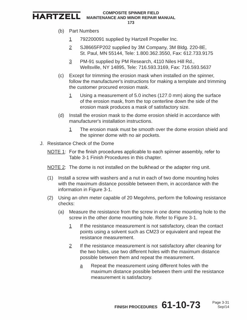
J. Resistance Check of the Dome
NOTE 1: For the finish procedures applicable to each spinner assembly, refer to Table 3-1 Finish Procedures in this chapter.
NOTE 2: The dome is not installed on the bulkhead or the adapter ring unit.
(1) Install a screw with washers and a nut in each of two dome mounting holes with the maximum distance possible between them, in accordance with the information in Figure 3-1.
(2) Using an ohm meter capable of 20 Megohms, perform the following resistance checks:
(a) Measure the resistance from the screw in one dome mounting hole to the screw in the other dome mounting hole. Refer to Figure 3-1.
1 If the resistance measurement is not satisfactory, clean the contact points using a solvent such as CM23 or equivalent and repeat the resistance measurement.
2 If the resistance measurement is not satisfactory after cleaning for the two holes, use two different holes with the maximum distance possible between them and repeat the measurement.
a Repeat the measurement using different holes with the maximum distance possible between them until the resistance measurement is satisfactory.
COMPOSITE SPINNER FIELD MAINTENANCE AND MINOR REPAIR MANUAL
173
Page 3-31Sep/1461-10-73FINISH PROCEDURES
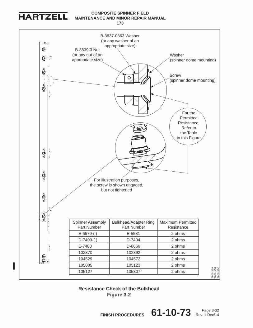
Resistance Check of the Bulkhead Figure 3-2
B-3837-0363 Washer (or any washer of an
appropriate size)B-3839-3 Nut
(or any nut of an appropriate size)
Washer (spinner dome mounting)
Screw (spinner dome mounting)
For the Permitted
Resistance, Refer to the Table
in this Figure
For illustration purposes, the screw is shown engaged,
but not tightened
Spinner Assembly Part Number
Bulkhead/Adapter Ring Part Number
Maximum Permitted Resistance
E-5579-( ) E-5581 2 ohmsD-7409-( ) D-7404 2 ohmsE-7480 D-6666 2 ohms102870 102892 2 ohms104529 104572 2 ohms105085 105123 2 ohms105127 105307 2 ohms
TI-0
0115
A TI
-001
15B
TI
-001
15C
COMPOSITE SPINNER FIELD MAINTENANCE AND MINOR REPAIR MANUAL
173
Page 3-32Rev. 1 Dec/1461-10-73FINISH PROCEDURES