HART® Connection Systems - MTL Instruments · 4.5 HTP-SC16x backplanes ... INM MTL4851_52 Rev1 1 1...
48
DRAFT - 27 November 2014 MTL4851 and MTL4852 HART® Connection Systems March 2015 INM 4851_52 Rev1 Instruction Manual MTL HART ® Interfacing Solutions
Transcript of HART® Connection Systems - MTL Instruments · 4.5 HTP-SC16x backplanes ... INM MTL4851_52 Rev1 1 1...
DRAFT - 27 November 2014
MTL4851 and MTL4852 HART® Connection Systems
March 2015INM 4851_52 Rev1
Instruction ManualMTL HART® Interfacing Solutions

DRAFT - 27 November 2014
ii
DRAFT - 27 November 2014 DRAFT - 27 November 2014
INM MTL4851_52 Rev1
DECLARATION OF CONFORMITY
We declare under our sole responsibility that the MTL4851 and MTL4852 and associated products listed below, to which this declaration relates, conform to the requirements of the Directives below by compliance with the standards listed:
1. Council Directive 2004/108/EC (EMC Directive) relating to Electro-Magnetic Compatibility. EN 61326-1:2006 Class A equipment. Table 2 - Industrial Locations
2. Council Directive 94/9/EC (ATEX Directive) relating to equipment and protective systems intended for use in potentially explosive atmospheres. EN 60079-0:2012, EN 60079-15:2010
Product Description EMC1 LVD2 ATEX3 Cat1/Cat2ATEX Cert No.
Cat3 ATEX Cert No.
MTL4851 HART multiplexer master
Yes N/R Yes None MTL08ATEX4850X
MTL4852 HART multiplexer secondary
Yes N/R Yes None MTL08ATEX4850X
HMx64 HART multiplexer carrier
Yes N/R Yes None MTL08ATEX4850X
HTP-SC16x HART multiplexer carrier
Yes N/R Yes None MTL08ATEX4850X
HCU16x HART connectionunit
Yes N/R Yes None MTL08ATEX4850X
Notes relating to CE Marking:
1. Entries in this column may be:
Yes Product conforms to the EMC Directive
N/R Product is not required to conform to the EMC Directive
2. Entries in this column may be:
Yes Product conforms to the LVD Directive
N/R Product is not required to conform to the LVD Directive
3. Entries in this column may be:
Yes Product conforms to the ATEX Directive
N/R Product is not required to conform to the ATEX Directive

DRAFT - 27 November 2014DRAFT - 27 November 2014 DRAFT - 27 November 2014
INM MTL4851_52 Rev1 iii
GENERAL SAFETY INFORMATION
The following methods are used in this manual to alert the user to important information:-
WARNING!
Warnings are provided to ensure operator safety and MUST be followed.
CAUTION
Cautions are provided to prevent damage to the instrument
NOTE
These are used to give general information to ensure correct operation
Safety instructions for installation and operating personnel
The operating instructions provided here contain essential safety instructions for installation personnel and those engaged in the operation, maintenance and servicing of the equipment.
WARNING!
Failure to comply with these instructions can endanger the lives or health of personnel and risk damage to the plant and the environment.
WARNING!
The responsibility for planning, installation, commissioning, operation and maintenance, particularly with respect to applications in explosion-hazard areas,
lies with the plant operator
Before commencing installation or commissioning:
• Read and understand the contents of this manual and the product datasheet
• Ensure installation and operating personnel have received adequate training for this task
• Ensure that any operating instructions are fully understood by the personnel responsible.
• Observe national and local installation and mounting regulations (e.g. IEC 60079-14).
WARNING!
If these assemblies have been used previously in general electrical
installations, they MAY NOT be used in explosion-hazard area applications.
During operation:
• Make the relevant instructions available at all times to the operating personnel.
• Observe safety instructions.
• Observe national safety and accident prevention regulations.
• Operate the equipment within its published specification.
• Servicing, maintenance work or repairs not described in this manual must not be performed without prior agreement with the manufacturer.
• Any damage to this equipment may render its explosion protection null and void.
• No changes to any of the components that might impair their explosion protection are permitted.
If any information provided here is not clear, contact MTL or one of its representatives.
NOTE
Incorrect installation and operation of this equipment can result in invalidation of the guarantee.
DRAFT - 27 November 2014DRAFT - 27 November 2014
iv
DRAFT - 27 November 2014
INM MTL4851_52 Rev1
CONTENTS
1 INTRODUCTION . . . . . . . . . . . . . . . . . . . . . . . . . . . . . . . . . . . . . . . . . . . . . . . . . . . . . . . . . . . . . . . . . . . . . . . . . . . . . . 1
2 DESCRIPTION . . . . . . . . . . . . . . . . . . . . . . . . . . . . . . . . . . . . . . . . . . . . . . . . . . . . . . . . . . . . . . . . . . . . . . . . . . . . . . . . 1
2.1 New features . . . . . . . . . . . . . . . . . . . . . . . . . . . . . . . . . . . . . . . . . . . . . . . . . . . . . . . . . . . . . . . . . . . . . . . . . . . . . .1
2.2 Compatibility . . . . . . . . . . . . . . . . . . . . . . . . . . . . . . . . . . . . . . . . . . . . . . . . . . . . . . . . . . . . . . . . . . . . . . . . . . . . .1
2.3 System structure . . . . . . . . . . . . . . . . . . . . . . . . . . . . . . . . . . . . . . . . . . . . . . . . . . . . . . . . . . . . . . . . . . . . . . . . . .2
2.4 General purpose or IS? . . . . . . . . . . . . . . . . . . . . . . . . . . . . . . . . . . . . . . . . . . . . . . . . . . . . . . . . . . . . . . . . . . . . .3
2.5 Generic or custom? . . . . . . . . . . . . . . . . . . . . . . . . . . . . . . . . . . . . . . . . . . . . . . . . . . . . . . . . . . . . . . . . . . . . . . . .3
2.6 Small or large-scale application? . . . . . . . . . . . . . . . . . . . . . . . . . . . . . . . . . . . . . . . . . . . . . . . . . . . . . . . . . . . . .3
2.6.1 Up to 80 field loops . . . . . . . . . . . . . . . . . . . . . . . . . . . . . . . . . . . . . . . . . . . . . . . . . . . . . . . . . . . . . . . . . . . . . . . .3
2.6.2 Installations likely to use more than 80 field loops . . . . . . . . . . . . . . . . . . . . . . . . . . . . . . . . . . . . . . . . . . . . . .3
2.7 Connection methods . . . . . . . . . . . . . . . . . . . . . . . . . . . . . . . . . . . . . . . . . . . . . . . . . . . . . . . . . . . . . . . . . . . . . . .4
3 SAFETY INFORMATION . . . . . . . . . . . . . . . . . . . . . . . . . . . . . . . . . . . . . . . . . . . . . . . . . . . . . . . . . . . . . . . . . . . . . . . 5
3.1 Precautions - General . . . . . . . . . . . . . . . . . . . . . . . . . . . . . . . . . . . . . . . . . . . . . . . . . . . . . . . . . . . . . . . . . . . . . . .5
3.2 Precautions - HMM64 & HMS64 . . . . . . . . . . . . . . . . . . . . . . . . . . . . . . . . . . . . . . . . . . . . . . . . . . . . . . . . . . . . . .5
4 INSTALLATION . . . . . . . . . . . . . . . . . . . . . . . . . . . . . . . . . . . . . . . . . . . . . . . . . . . . . . . . . . . . . . . . . . . . . . . . . . . . . . . 5
4.1 System overview . . . . . . . . . . . . . . . . . . . . . . . . . . . . . . . . . . . . . . . . . . . . . . . . . . . . . . . . . . . . . . . . . . . . . . . . . .5
4.2 HMM64 & HMS64 HART backplanes . . . . . . . . . . . . . . . . . . . . . . . . . . . . . . . . . . . . . . . . . . . . . . . . . . . . . . . . . .5
4.2.1 Mounting . . . . . . . . . . . . . . . . . . . . . . . . . . . . . . . . . . . . . . . . . . . . . . . . . . . . . . . . . . . . . . . . . . . . . . . . . . . . . . . . .7
4.2.2 DC power connection . . . . . . . . . . . . . . . . . . . . . . . . . . . . . . . . . . . . . . . . . . . . . . . . . . . . . . . . . . . . . . . . . . . . . .7
4.2.3 HART signal connections. . . . . . . . . . . . . . . . . . . . . . . . . . . . . . . . . . . . . . . . . . . . . . . . . . . . . . . . . . . . . . . . . . . .7
4.2.4 Links from additional HMS64 backplanes . . . . . . . . . . . . . . . . . . . . . . . . . . . . . . . . . . . . . . . . . . . . . . . . . . . . . .7
4.2.5 MTL4851/52 modules fitting and configuration . . . . . . . . . . . . . . . . . . . . . . . . . . . . . . . . . . . . . . . . . . . . . . . . .8
4.2.6 RS485 communication connections . . . . . . . . . . . . . . . . . . . . . . . . . . . . . . . . . . . . . . . . . . . . . . . . . . . . . . . . . . .8
4.2.7 HART address switches . . . . . . . . . . . . . . . . . . . . . . . . . . . . . . . . . . . . . . . . . . . . . . . . . . . . . . . . . . . . . . . . . . . . .8
4.2.8 ALARM connection . . . . . . . . . . . . . . . . . . . . . . . . . . . . . . . . . . . . . . . . . . . . . . . . . . . . . . . . . . . . . . . . . . . . . . . .8
4.3 HCU16 HART connection unit . . . . . . . . . . . . . . . . . . . . . . . . . . . . . . . . . . . . . . . . . . . . . . . . . . . . . . . . . . . . . . . .9
4.4 HCU16AO HART connection unit . . . . . . . . . . . . . . . . . . . . . . . . . . . . . . . . . . . . . . . . . . . . . . . . . . . . . . . . . . . .10
4.5 HTP-SC16x backplanes . . . . . . . . . . . . . . . . . . . . . . . . . . . . . . . . . . . . . . . . . . . . . . . . . . . . . . . . . . . . . . . . . . . .13
4.5.1 Application examples . . . . . . . . . . . . . . . . . . . . . . . . . . . . . . . . . . . . . . . . . . . . . . . . . . . . . . . . . . . . . . . . . . . . .13
4.5.2 Mounting . . . . . . . . . . . . . . . . . . . . . . . . . . . . . . . . . . . . . . . . . . . . . . . . . . . . . . . . . . . . . . . . . . . . . . . . . . . . . . . .15
4.5.3 DC power connection . . . . . . . . . . . . . . . . . . . . . . . . . . . . . . . . . . . . . . . . . . . . . . . . . . . . . . . . . . . . . . . . . . . . .15
4.5.4 Field wiring (loop) connections . . . . . . . . . . . . . . . . . . . . . . . . . . . . . . . . . . . . . . . . . . . . . . . . . . . . . . . . . . . . .15
4.5.5 Linking additional HTP-SC16S backplanes . . . . . . . . . . . . . . . . . . . . . . . . . . . . . . . . . . . . . . . . . . . . . . . . . . . .15
4.5.6 MTL4851/52 modules fitting and configuration . . . . . . . . . . . . . . . . . . . . . . . . . . . . . . . . . . . . . . . . . . . . . . . .15
4.5.7 RS485 communication connections . . . . . . . . . . . . . . . . . . . . . . . . . . . . . . . . . . . . . . . . . . . . . . . . . . . . . . . . . .15
4.5.8 RS485 address switch . . . . . . . . . . . . . . . . . . . . . . . . . . . . . . . . . . . . . . . . . . . . . . . . . . . . . . . . . . . . . . . . . . . . .16
4.5.9 Alarm connection . . . . . . . . . . . . . . . . . . . . . . . . . . . . . . . . . . . . . . . . . . . . . . . . . . . . . . . . . . . . . . . . . . . . . . . . .16
4.6 CPH-SC16x backplanes . . . . . . . . . . . . . . . . . . . . . . . . . . . . . . . . . . . . . . . . . . . . . . . . . . . . . . . . . . . . . . . . . . . .16
4.6.1 RS485 communication connections . . . . . . . . . . . . . . . . . . . . . . . . . . . . . . . . . . . . . . . . . . . . . . . . . . . . . . . . . .18
4.6.2 DC power connections . . . . . . . . . . . . . . . . . . . . . . . . . . . . . . . . . . . . . . . . . . . . . . . . . . . . . . . . . . . . . . . . . . . . .18
4.6.3 HART addressing . . . . . . . . . . . . . . . . . . . . . . . . . . . . . . . . . . . . . . . . . . . . . . . . . . . . . . . . . . . . . . . . . . . . . . . . .18
4.7 Mechanical mounting of backplanes . . . . . . . . . . . . . . . . . . . . . . . . . . . . . . . . . . . . . . . . . . . . . . . . . . . . . . . . .18
4.7.1 Surface mounting . . . . . . . . . . . . . . . . . . . . . . . . . . . . . . . . . . . . . . . . . . . . . . . . . . . . . . . . . . . . . . . . . . . . . . . . .19
4.7.2 DIN-rail mounting . . . . . . . . . . . . . . . . . . . . . . . . . . . . . . . . . . . . . . . . . . . . . . . . . . . . . . . . . . . . . . . . . . . . . . . . .19
DRAFT - 27 November 2014DRAFT - 27 November 2014
INM MTL4851_52 Rev1 v
DRAFT - 27 November 2014
4.8 Backplanes – identification and tagging . . . . . . . . . . . . . . . . . . . . . . . . . . . . . . . . . . . . . . . . . . . . . . . . . . . . . .20
4.9 Backplane earth rails . . . . . . . . . . . . . . . . . . . . . . . . . . . . . . . . . . . . . . . . . . . . . . . . . . . . . . . . . . . . . . . . . . . . . .21
4.10 Backplanes – connections . . . . . . . . . . . . . . . . . . . . . . . . . . . . . . . . . . . . . . . . . . . . . . . . . . . . . . . . . . . . . . . . . .22
4.10.1 Hazardous area - field wiring connections . . . . . . . . . . . . . . . . . . . . . . . . . . . . . . . . . . . . . . . . . . . . . . . . . . . . .22
4.10.2 Safe area - control system connections . . . . . . . . . . . . . . . . . . . . . . . . . . . . . . . . . . . . . . . . . . . . . . . . . . . . . . .22
4.10.3 Power supply connections . . . . . . . . . . . . . . . . . . . . . . . . . . . . . . . . . . . . . . . . . . . . . . . . . . . . . . . . . . . . . . . . .22
4.10.4 Safe area – “ring-main” power supplies . . . . . . . . . . . . . . . . . . . . . . . . . . . . . . . . . . . . . . . . . . . . . . . . . . . . . .23
4.11 MTL customised backplanes . . . . . . . . . . . . . . . . . . . . . . . . . . . . . . . . . . . . . . . . . . . . . . . . . . . . . . . . . . . . . . . .24
4.12 General cabling recommendations . . . . . . . . . . . . . . . . . . . . . . . . . . . . . . . . . . . . . . . . . . . . . . . . . . . . . . . . . .24
4.12.1 HART signals cables . . . . . . . . . . . . . . . . . . . . . . . . . . . . . . . . . . . . . . . . . . . . . . . . . . . . . . . . . . . . . . . . . . . . . . .24
4.12.2 RS485 connection . . . . . . . . . . . . . . . . . . . . . . . . . . . . . . . . . . . . . . . . . . . . . . . . . . . . . . . . . . . . . . . . . . . . . . . . .25
4.12.3 RS485 2-wire interconnection . . . . . . . . . . . . . . . . . . . . . . . . . . . . . . . . . . . . . . . . . . . . . . . . . . . . . . . . . . . . . . .26
4.12.4 Data converters. . . . . . . . . . . . . . . . . . . . . . . . . . . . . . . . . . . . . . . . . . . . . . . . . . . . . . . . . . . . . . . . . . . . . . . . . . .26
5 MODULES . . . . . . . . . . . . . . . . . . . . . . . . . . . . . . . . . . . . . . . . . . . . . . . . . . . . . . . . . . . . . . . . . . . . . . . . . . . . . . . . . . 27
5.1 MTL4851/52 – installation . . . . . . . . . . . . . . . . . . . . . . . . . . . . . . . . . . . . . . . . . . . . . . . . . . . . . . . . . . . . . . . . . .27
5.2 Isolator modules (if used) . . . . . . . . . . . . . . . . . . . . . . . . . . . . . . . . . . . . . . . . . . . . . . . . . . . . . . . . . . . . . . . . . .27
5.3 Set-up and configuration. . . . . . . . . . . . . . . . . . . . . . . . . . . . . . . . . . . . . . . . . . . . . . . . . . . . . . . . . . . . . . . . . . .27
5.3.1 HART address . . . . . . . . . . . . . . . . . . . . . . . . . . . . . . . . . . . . . . . . . . . . . . . . . . . . . . . . . . . . . . . . . . . . . . . . . . . .27
5.3.2 Operation at power-up . . . . . . . . . . . . . . . . . . . . . . . . . . . . . . . . . . . . . . . . . . . . . . . . . . . . . . . . . . . . . . . . . . . . .28
6 FAULT FINDING AND ROUTINE MAINTENANCE . . . . . . . . . . . . . . . . . . . . . . . . . . . . . . . . . . . . . . . . . . . . . . . . . . . 28
6.1 Fault finding procedures for MTL4851 and MTL4852 modules . . . . . . . . . . . . . . . . . . . . . . . . . . . . . . . . . . . . . . . . 28
6.1.1 MTL4851 module . . . . . . . . . . . . . . . . . . . . . . . . . . . . . . . . . . . . . . . . . . . . . . . . . . . . . . . . . . . . . . . . . . . . . . . . .28
6.1.2 MTL4852 module . . . . . . . . . . . . . . . . . . . . . . . . . . . . . . . . . . . . . . . . . . . . . . . . . . . . . . . . . . . . . . . . . . . . . . . . .29
6.2 Fault finding on isolator backplanes . . . . . . . . . . . . . . . . . . . . . . . . . . . . . . . . . . . . . . . . . . . . . . . . . . . . . . . . .29
6.3 Maintenance precautions for MTL4500 modules on backplane . . . . . . . . . . . . . . . . . . . . . . . . . . . . . . . . . . .30
6.4 Routine maintenance . . . . . . . . . . . . . . . . . . . . . . . . . . . . . . . . . . . . . . . . . . . . . . . . . . . . . . . . . . . . . . . . . . . . . .30
7 SOFTWARE CONNECTIVITY . . . . . . . . . . . . . . . . . . . . . . . . . . . . . . . . . . . . . . . . . . . . . . . . . . . . . . . . . . . . . . . . . . . 30
7.1 Introduction . . . . . . . . . . . . . . . . . . . . . . . . . . . . . . . . . . . . . . . . . . . . . . . . . . . . . . . . . . . . . . . . . . . . . . . . . . . . .30
7.2 Communication modes . . . . . . . . . . . . . . . . . . . . . . . . . . . . . . . . . . . . . . . . . . . . . . . . . . . . . . . . . . . . . . . . . . . .31
7.3 Software setup . . . . . . . . . . . . . . . . . . . . . . . . . . . . . . . . . . . . . . . . . . . . . . . . . . . . . . . . . . . . . . . . . . . . . . . . . . .31
8 APPLICATIONS INVOLVING ZONE 2 HAZARDOUS AREAS . . . . . . . . . . . . . . . . . . . . . . . . . . . . . . . . . . . . . . . . . . 32
8.1 General . . . . . . . . . . . . . . . . . . . . . . . . . . . . . . . . . . . . . . . . . . . . . . . . . . . . . . . . . . . . . . . . . . . . . . . . . . . . . . . . .32
8.2 Installation . . . . . . . . . . . . . . . . . . . . . . . . . . . . . . . . . . . . . . . . . . . . . . . . . . . . . . . . . . . . . . . . . . . . . . . . . . . . . .32
8.3 Inspection and maintenance . . . . . . . . . . . . . . . . . . . . . . . . . . . . . . . . . . . . . . . . . . . . . . . . . . . . . . . . . . . . . . . .32
8.4 Repair . . . . . . . . . . . . . . . . . . . . . . . . . . . . . . . . . . . . . . . . . . . . . . . . . . . . . . . . . . . . . . . . . . . . . . . . . . . . . . . . . .33
8.5 Marking . . . . . . . . . . . . . . . . . . . . . . . . . . . . . . . . . . . . . . . . . . . . . . . . . . . . . . . . . . . . . . . . . . . . . . . . . . . . . . . . .33
APPENDIX A - TYPICAL COMPATIBLE SYSTEMS. . . . . . . . . . . . . . . . . . . . . . . . . . . . . . . . . . . . . . . . . . . . . . . . . . . . . . . . . . . 34
APPENDIX B - ALARM EVENT LOG. . . . . . . . . . . . . . . . . . . . . . . . . . . . . . . . . . . . . . . . . . . . . . . . . . . . . . . . . . . . . . . . . . . . . . 34
APPENDIX C - COMPATABILITY WITH EARLIER MTL4840 SYSTEM. . . . . . . . . . . . . . . . . . . . . . . . . . . . . . . . . . . . . . . . . . . 37
APPENDIX D - INTEGRATION OF NEW EQUIPMENT INTO EARLIER INSTALLATIONS . . . . . . . . . . . . . . . . . . . . . . . . . . 38

DRAFT - 27 November 2014
vi
DRAFT - 27 November 2014 DRAFT - 27 November 2014
INM MTL4851_52 Rev1
THIS PAGE IS LEFT INTENTIONALLY BLANK

DRAFT - 27 November 2014DRAFT - 27 November 2014 DRAFT - 27 November 2014
INM MTL4851_52 Rev1 1
1 INTRODUCTIONThis instruction manual describes the procedures for installing, connecting, checking and maintaining the MTL4851/52 HART® maintenance system, which is a simple interface between ‘smart’ devices in the field and HART instrument management software running on a PC/workstation.
The following sections are outlined here.
Section 2 describes the system and the solutions available
Section 3 covers some important safety aspects.
Section 4 deals with installing the backplanes
Section 5 describes the installation and configuration of the modules
Section 6 provides information on fault-finding, and maintenance
Section 7 introduces software for the MTL4851/52 system.
See the MTL web site (www.mtl-inst.com) for the full specifications of the MTL4851/52 system components and accessories, and of the MTL4500 Series isolators that are frequently used with this system.
2 DESCRIPTION
2.1 New featuresThe MTL4851/52 HART Maintenance System is the “next generation” leading on from the popular MTL4840 system enabling a user to calibrate, configure and maintain an entire network of ‘smart’ field devices from a single workstation. While similar in a number of ways to the earlier MTL4840 system, the newer MTL4851/52 system offers greater speed; compatibility with newer versions of HART devices, e.g. Rev. 5, 6 and 7; simpler setup using fewer parameter definitions; an Ethernet communication option, and easier integration into custom interface solutions.
2.2 CompatibilityWhile the MTL4851/52 system is the recommended path for new installations, it can work effectively alongside existing MTL4840 equipment. Although the modules are not plug compatible, and therefore use different carriers, they can readily occupy adjacent RS485 addresses on the system and work in harmony with existing installations. See also Appendix C & D for additional information on integration and maintenance of existing systems.
MTL4851/52 HART multiplexer
Figure 1.1 - HMM64 and HTP-SC16M HART multiplexer carriers

DRAFT - 27 November 2014DRAFT - 27 November 2014
2
DRAFT - 27 November 2014
INM MTL4851_52 Rev1
2.3 System structureThe controlling elements are the MTL4851 ‘Master’ and MTL4852 ‘Secondary’ HART interface modules, respectively. These two new modules, like their predecessors, provide the means for multiplexing HART signals for the individual field devices, making each one addressable and identifiable.
Also important are the circuit boards that simplify the interconnection of the field devices to the MTL4851/52 modules. Carriers, terminal boards and backplanes are available to suit general applications but custom versions can also be designed to suit individual OEMs and their applications.
The MTL4851and MTL4852 modules use the same case style as the current MTL4850 HART multiplexer, providing a quick and easy installation method onto the backplanes.
The system is organised in multiples of 16 (sixteen), and reference to Figure 2.1 will assist the user in understanding the way the system interconnects. The MTL4851 and the MTL4852 modules are similar in that both have sixteen channels for individual field devices; however, the MTL4851 ‘Master’ module also has control facilities to enable it to manage up to fifteen MTL4852 ‘Secondary’ modules connected to it, as well as an RS485 interface allowing it to communicate with the workstation running the management software.
HART® is a registered trademark of the HART Communication Foundation
Safe areaHazardous area
Figure 2.1 - System Overview (typical installation)
Workstation PCrunning instrumentmanagement software Up to 7936 HART® devices
Ethernet/RS485convertor
I
P
I
P
Process controlsystem eg DCS, PLC
Ethernet
RS485
1–16
2 1611
15
22
161 15
1–16 1–16 1–16
1–161–16 1–16 1–16
MTL4852
MTL4852
MTL4852
MTL4851
HART transmittersand valve
4/20mA+ HARTsignals
1
2
16
I5
HARTsignalsMTL
4541
MTL4546
HARTsignals
HARTsignals
HARTsignals
Each MTL485x module will handle up to 16 channels
To up to a total of 31
MTL4851 modules
Terminal
Terminal
MTL4852
MTL4852
MTL4852
MTL4851

DRAFT - 27 November 2014DRAFT - 27 November 2014
INM MTL4851_52 Rev1 3
DRAFT - 27 November 2014
2.4 General purpose or IS?
NOTE
For intrinsically safe (IS) applications, consideration must be given to the safety parameters for each loop. For further information please refer to MTL or your local representative.
MTL’s HART Management Systems can be used to control and maintain field devices that are located in safe area or hazardous areas.
For safe areas, HART Connection Units (HCUs) - described in Sections 4.3 and 4.4 - provide the necessary terminals to connect up to 16 field devices, with organised links to the MTL4851/52 interface modules.
Hazardous-area field devices can be handled through IS isolating interfaces mounted on backplanes, such as the CPH-SC16M and CPH-SC16S. Having the isolators mounted on a backplane dramatically reduces the amount of hand wiring required and therefore reduces the number of potential wiring errors. The hazardous-area wiring terminates on the isolating modules, not the backplane, consequently the backplanes do not need IS certification.
2.5 Generic or custom?A range of generic connection units is available for both input and output field-device wiring. These are not designed for any particular DCS type and may be used universally.
The alternative is to choose a connection unit or backplane that integrates with the type of DCS being used on the plant. The key advantage of this method is the backplane’s use of a DCS’s specific connector type, which simplifies and unifies the wiring of the connection units into the system. Various solutions are available to suit individual DCS types and MTL or one its representatives should be consulted for further details.
2.6 Small or large-scale application?MTL’s HART maintenance solution is capable of addressing many thousands of field devices, but many real world applications are significantly smaller than this.
2.6.1 Up to 80 field loops
MTL has devised a simple, integrated solution to handle up to 80 field devices, in multiples of sixteen, to suit smaller installations, by using the following carriers.
HTP-SC16M Master carrier with one MTL4851 and up to 16 field device signals
HTP-SC16S Secondary carrier with one MTL4852 and up to 16 field device signals
Four of the HTP-SC16S carriers can be ‘daisy-chained’ back to the HTP-SC16M to provide a total of 80 loops from one RS485 address. See Section 4.6 for further details.
Other carriers/backplanes, including those for intrinsic safety interfaces, employ a similar regime to handle up to 80 loops.
NOTE
MTL encourages users and potential users to discuss their requirements with their local representative to ensure that the optimum solution is recognised for any given application
2.6.2 Installations likely to use more than 80 field loops
For installations required to accommodate more than 80 loops, the system should probably be based upon the HMM64 and HMS64 HART backplanes - see Section 4.2. An HMM64 backplane will accommodate one MTL4851 master module and up to three MTL4852 secondary modules to accommodate a total of 64 loops. A further three HMS64 backplanes, each carrying four MTL4852 modules, can be ‘daisy-chained’ back to the HMM64, providing an extra 3 x 64 loops for a total of 256, all provided from one RS485 address location.
By repeating this structure a further 30 times it is possible to service a total of 7,936 loops!

DRAFT - 27 November 2014DRAFT - 27 November 2014
4
DRAFT - 27 November 2014
INM MTL4851_52 Rev1
CAUTION
Speed-of-operation can be affected when too many field devices are addressed on a system. The speed of polling and response times should always be taken into account when planning
a HART maintenance system.
2.7 Connection methodsThere are essentially three methods of interfacing to the HART signals that are carried on the loop wiring:
a) via a basic connection unit - e.g. an HCU style unit linked to a backplane fitted with MTL4851 and MTL4852 modules
b) via a generic or customised I/O isolator module backplane - linked to a backplane fitted with MTL4851 and MTL4852 modules
c) via a HART + I/O module backplane - e.g. a CPH style backplane with I/O modules and a dedicated MTL4851 or MTL4852 module
A basic HCU connection unit - see Figure 2.2 - has one set of screw terminals for the field devices and another set of screw terminals for connection to the main system. The HART signals are derived from the combined signals passing through the connection unit and routed to the HART maintenance system. This connection unit method is normally used for field devices in non-hazardous area
The second method of getting the HART signals for the maintenance system is to pick them off a generic or customised backplane used to accommodate intrinsic safety isolators, e.g. MTL4500 Series units as illustrated in Figure 2.3.
The backplane can be customised to provide a host/system connector that best suits the user’s choice of DCS or PLC.
In both of the above two cases the derived HART signals are routed to a backplane fitted with either an MTL4581 and/or an MTL4852 multiplexer for their transmission to the maintenance system.
The third alternative is to use a backplane that integrates both the I/O modules and an MTL4581 or MTL4852 multiplexer with an RS485 port that links it to the management system and this method is discussed in Section 4.8.
To HMP-HM64HART Interface
MTL485x
software
Figure 2.2 – Generic HCU connection unit
Figure 2.3 – I/O isolator module backplane connection unit
DRAFT - 27 November 2014DRAFT - 27 November 2014
INM MTL4851_52 Rev1 5
DRAFT - 27 November 2014
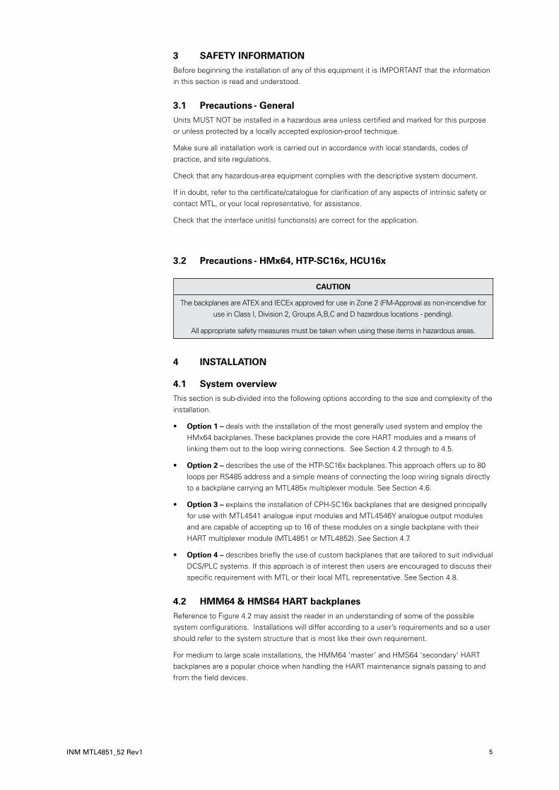
3 SAFETY INFORMATIONBefore beginning the installation of any of this equipment it is IMPORTANT that the information in this section is read and understood.
3.1 Precautions - GeneralUnits MUST NOT be installed in a hazardous area unless certified and marked for this purpose or unless protected by a locally accepted explosion-proof technique.
Make sure all installation work is carried out in accordance with local standards, codes of practice, and site regulations.
Check that any hazardous-area equipment complies with the descriptive system document.
If in doubt, refer to the certificate/catalogue for clarification of any aspects of intrinsic safety or contact MTL, or your local representative, for assistance.
Check that the interface unit(s) functions(s) are correct for the application.
3.2 Precautions - HMx64, HTP-SC16x, HCU16x
CAUTION
The backplanes are ATEX and IECEx approved for use in Zone 2 (FM-Approval as non-incendive for use in Class I, Division 2, Groups A,B,C and D hazardous locations - pending).
All appropriate safety measures must be taken when using these items in hazardous areas.
4 INSTALLATION
4.1 System overviewThis section is sub-divided into the following options according to the size and complexity of the installation.
• Option 1 – deals with the installation of the most generally used system and employ the HMx64 backplanes. These backplanes provide the core HART modules and a means of linking them out to the loop wiring connections. See Section 4.2 through to 4.5.
• Option 2 – describes the use of the HTP-SC16x backplanes. This approach offers up to 80 loops per RS485 address and a simple means of connecting the loop wiring signals directly to a backplane carrying an MTL485x multiplexer module. See Section 4.6.
• Option 3 – explains the installation of CPH-SC16x backplanes that are designed principally for use with MTL4541 analogue input modules and MTL4546Y analogue output modules and are capable of accepting up to 16 of these modules on a single backplane with their HART multiplexer module (MTL4851 or MTL4852). See Section 4.7.
• Option 4 – describes briefly the use of custom backplanes that are tailored to suit individual DCS/PLC systems. If this approach is of interest then users are encouraged to discuss their specific requirement with MTL or their local MTL representative. See Section 4.8.
4.2 HMM64 & HMS64 HART backplanesReference to Figure 4.2 may assist the reader in an understanding of some of the possible system configurations. Installations will differ according to a user’s requirements and so a user should refer to the system structure that is most like their own requirement.
For medium to large scale installations, the HMM64 ‘master’ and HMS64 ‘secondary’ HART backplanes are a popular choice when handling the HART maintenance signals passing to and from the field devices.

DRAFT - 27 November 2014DRAFT - 27 November 2014
6
DRAFT - 27 November 2014
INM MTL4851_52 Rev1
The HMM64 ‘Master’ backplane accommodates 1 x MTL4851 ‘master’ module (16 loops) and up to 3 x MTL4852 ‘secondary’ modules (an additional 3 x 16 loops) for a total of 64 loops. One MTL4851 ‘master’ module can however support up to 15 x MTL4852 modules, and so the system has been designed to expand easily by ‘daisy-chaining’ additional HMS64 backplanes, each carrying 4 x MTL4852 ‘Secondary’ modules. See Figure 4.2.
HMM64 HMS64
155
125.4
155
125.4
Figure 4.1 – HMM64 and HMS64 backplane units
To additional30 (max.)HMM64
backplanes
RS485Comms
HMM64
MTL4851
HART
HCU16
HCU16AO
CUSTOMISED BACKPLANE
HART
HART
HMS64
HMS64
HMS64
Additional+ 64ch
Additional+ 16ch
DCSterminals
DCSterminals
DCSterminals
16chHART
outputs(filtered)
16ch4-20mA
analogue+ HARTsignals
16ch to DCSanalogue input/output
16chHART
inputs oroutputs
Additional+ 64ch
HARTcables
HM64RIB20-x.x
Additional+ 64ch
+24V
linksbetween
backplanesHMRIB16-x.x
Max. total length 4m
Figure 4.2 – System diagram showing an HMM64 together with all three permitted HMS4 backplanes and other key components

DRAFT - 27 November 2014DRAFT - 27 November 2014
INM MTL4851_52 Rev1 7
DRAFT - 27 November 2014
4.2.1 Mounting
The HMM64 and HMS64 backplanes are designed for mounting in a control room equipment cabinet and are supplied fitted on a carrier suitable for T- or G- section DIN-rail mounting in any orientation.
HMM64 HMS64
Weight (excluding modules): 215g approx. 200g approx.
MTL4851 MTL4852
Weight of module: 95g approx. 75g approx.
Footprint dimensions: See Figure 4.2
Height (modules fitted): 155mm from top of DIN rail
4.2.2 DC power connection
DC power is required on the HMM64 only. HMS64 backplanes receive their power through the cable from the HMM64 or the preceding HMS64 backplane.
The HMM64 has a removable, 4-way, screw-clamp terminal connector that provides for redundant 24V dc supply connections.
Power requirements: Voltage: 21–35V dc SELV
Current: 72mA @ 24V dc
Connect the dc power to the board as shown in Figure 4.3. Single or dual power feeds may be applied.
4.2.3 HART signal connections
Each MTL4851/52 module has a DIN41651 connector (P1–P4) beside it to accept a 20-way ribbon cable. MTL can provide 20-way cables in a range of different lengths (x.x) on request (part. # HM64RIB20-x.x).
Each one provides 16 signal connection pins and 4 ground return pins for the module. These connectors receive the HART signals coming from either connection units or backplanes equipped with similar DIN41651 connectors. See Section 4.12 for cabling recommendations and limits.
Connect the ribbon cables to the appropriate connector for the corresponding MTL4851/52 module.
4.2.4 Links from additional HMS64 backplanes
A chain of up to three additional HMS64 backplanes may be linked back to the HMM64 master to provide a total of sixteen MTL485x modules – i.e. 256 channels – from a single HART address (see Figure 4.2). 16-way connectors labelled ‘NEXT’ and ‘PREVIOUS’ (Figure 4.1) are used to link the backplanes together as illustrated in Figure 4.2.
See Section 4.12 for cabling recommendations and limits. MTL can provide 16-way cables in a range of different lengths on request (part. # HMRIB16-x.x)
NOTE
The maximum total length between Master and all Secondary backplanes is 4m.
0V0V12POWER
PSU 124V
power in
–– ++
PSU 224V
power in
Figure 4.3 - DC power connections

DRAFT - 27 November 2014DRAFT - 27 November 2014
8
DRAFT - 27 November 2014
INM MTL4851_52 Rev1
4.2.5 MTL4851/52 modules fitting and configuration
The module fitting and configuration depends upon the backplane concerned. The HMM64 backplane will always be the first in the chain.
HMM64 The MTL4851 module must be fitted in position ‘1’ closest to the RS485 address switches – and the only one labelled to accept the MTL4851. The other three positions are used for MTL4852 modules. These may be fitted in any order, as the MTL4851 will allocate an address without any further intervention from the installer.
HMS64 The MTL4852 modules may be fitted in any order as the MTL4851 on the ‘master’ will allocate an address without any further intervention from the installer.
See Section 5 for further details.
4.2.6 RS485 communication connections
Two sets of RS485 connections are provided on the board - see Figure 4.1 or 4.2. These are used to connect the HMM64 backplane to the PC running the maintenance software and to onward link to other HART addressed backplanes. The provision of multiple terminals avoids the need to insert two wires into the same terminal position.
Further details of the RS485 link are provided in Sections 4.12.2 and 4.12.3.
4.2.7 HART address switches
Information on the address switches and their settings is covered in Section 5.3.
4.2.8 ALARM connection
The MTL4851 maintains a log of alarm events – see Appendix B – and is equipped with an alarm indicator to signal the occurrence of these alarm events. If one, or more, of these alarm conditions occurs the “Fault” LED on the module will light. In addition, the connector located on the HMM64 carrier provides an open collector output, referenced to 0V that may be used to link the alarm condition signal to an external alarm circuit.
The table below indicates the maximum values associated with the open collector “OUT” port.
Parameter Maximum rating
Supply voltage 35V
Collector current 5mA
Power dissipation 100mW
NOTE
For convenience, it is possible to reset the alarm condition from the HMM64 board. This avoids the need to go to the maintenance software workstation to reset it.
To reset the alarm - interrupt the current flowing through the alarm circuit for a period of greater than 1 second, see Figure 4.4 below.
OUT
0VALA
RM
0V
+V (35V max.)
(5mA max.)
Load(e.g. LED, relay, etc)
Break circuitfor >1sec
Figure 4.5 – Alarm connections
0V OUT
ALARM
Figure 4.4 – INM4851 Alarm reset

DRAFT - 27 November 2014DRAFT - 27 November 2014
INM MTL4851_52 Rev1 9
DRAFT - 27 November 2014
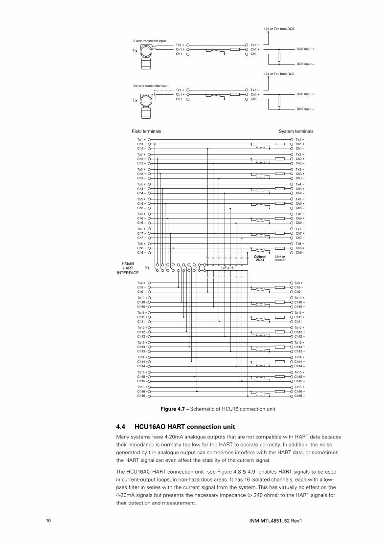
4.3 HCU16 HART connection unitThe HCU16 HART connection unit - see Figures 4.6 & 4.7 - provides a termination interface (for use in non-hazardous areas) for the field wiring and an onward link to the host/system control. It also provides a take-off point for the HART signals to the maintenance system.
Connections to the field signals and to the host/system are via screw-clamp terminals along each side of the backplane. Each channel has three terminals: +ve, -ve and a transmitter supply terminal (Tx +) – see Figure 4.5.
The link to the HMM64 or HMS64 is via a 20-way ribbon cable (HM64RIB20-x.x) that plugs into the DIN41651 style connector (P1) on the short edge of the backplane.
NOTE
HCU16 backplanes may be marked with “HMx64 HART interface” or “BPHM64 HART interface”. Both models can be used with the HMx64 boards because the pin identities and cable connectors are the same.
For optimum performance, HART signal need to be terminated with a minimum impedance of approximately 240 ohms. Positions are provided on the circuit board to fit parallel resistors (normally 250 ohms), or an appropriate series resistor to make up the difference if it is less than 240 ohms. The HCU16 unit can be used with analogue outputs if the system’s current signal is compatible with HART communications.
The HCU16 backplane is supplied fitted in a carrier for DIN-rail mounting. The footprint of the carrier is 150 x 125mm and the height from the top face of T-section DIN rail is approximately 55mm.
HMx64HART
INTERFACE
Figure 4.6 – HCU16 connection unit
DRAFT - 27 November 2014
10
DRAFT - 27 November 2014 DRAFT - 27 November 2014
INM MTL4851_52 Rev1
HMx64HART
INTERFACE
4.4 HCU16AO HART connection unitMany systems have 4-20mA analogue outputs that are not compatible with HART data because their impedance is normally too low for the HART to operate correctly. In addition, the noise generated by the analogue output can sometimes interfere with the HART data, or sometimes the HART signal can even affect the stability of the current signal.
The HCU16AO HART connection unit - see Figure 4.8 & 4.9 - enables HART signals to be used in current-output loops, in non-hazardous areas. It has 16 isolated channels, each with a low-pass filter in series with the current signal from the system. This has virtually no effect on the 4-20mA signals but presents the necessary impedance (> 240 ohms) to the HART signals for their detection and measurement.
Figure 4.7 – Schematic of HCU16 connection unit

DRAFT - 27 November 2014DRAFT - 27 November 2014 DRAFT - 27 November 2014
INM MTL4851_52 Rev1 11
��� ���
����� ������
�
�
�
�
�
�
�
�
���
�
�
�
�
�
�
�
�
�
�
�
�
�
�
�
�
���
�
�
�
�
�
�
�
�
�
�
�
�
�
�
�
�
�
�
�
�
�
�
�
�
���
���
�
�
�
�
�
�
�
�
���
�
�
�
�
�
�
�
�
���
����
������
�����
�
Figure 4.8 – HCU16AO connection unit

DRAFT - 27 November 2014
12
DRAFT - 27 November 2014 DRAFT - 27 November 2014
INM MTL4851_52 Rev1
As with the HCU16, the HART data is transferred to the HMM64 or HMS64 HART multiplexer interface via a 20-way ribbon cable (P1).
NOTE
HCU16AO backplanes may be marked with “HMx64 HART interface” or “BPHM64 HART interface”. Both models can be used with the HMx64 boards because the pin
identities and cable connectors are the same.
Field and system connections are made via pluggable 8-way, screw-clamp terminals, in 4 groups of 4 channels.
The HCU16AO is supplied in a carrier for DIN rail mounting.
Overall footprint of carrier: 275 x 125mm.
Height from top of DIN rail to top of screw connectors: 58mm
HMx64HART
INTERFACE

DRAFT - 27 November 2014DRAFT - 27 November 2014 DRAFT - 27 November 2014
INM MTL4851_52 Rev1 13
4.5 HTP-SC16x backplanesThe HTP-SC16M and the HTP-SC16S are master and secondary backplanes mounted on carriers as shown in Figure 4.9. Each backplane will provide for 16 field loops. These are linked in a chain beginning with the HTP-SC16M followed by up to four HTP-SC16S backplanes. This method will accommodate up to 80 field device loops on one RS485 address. Additional chains may be added by onward-linking the RS485 connection with different addresses.
As a simple solution for handling the HART maintenance signals passing to and from the field devices the HTP-SC16x will often be the primary method of choice. It is intended for analogue input signals but may also be used for analogue outputs if the host system is compatible with HART communications. Able to handle up to 16 channels through its screw-clamp field and system terminals, it is a convenient way to integrate HART maintenance facilities. The HTP-SC16x provides a self-contained solution because the MTL4851/52 HART multiplexer is already on-board and requires only DC power and a simple RS485 link to the host management PC to get started. Two terminals are provided for each channel enabling connections to be made to 2-wire transmitters, 4/20mA current loops or voltage inputs. Each channel is isolated so it may be connected to any suitable point in the analogue loop, and input and output types may be mixed. HART signals have to be terminated into an impedance of >240Ω, so provision is made as an option on the circuit board to fit a series resistor if the input impedance at the point of connection is <240Ω. The models including this option are identified with a –S240 suffix.
4.5.1 Application examples
125.4
155
125.4
155
HTP-SC16M
-CCHTP-SC16S
-S240-S240CC
0VO
UT
ALA
RM
12
0V0V
PO
WE
RA
BC
PREVIOUS
ON
14
1632
82
HA
RT
AD
DR
ES
S
FIELD
NEXT
A
SYSTEM
AB
B
1
2
3
4
5
6
7
8
9
10
11
12
13
14
15
16
1
2
3
4
5
6
7
8
9
10
11
12
13
14
15
16
!
AB
C
DATECODELABEL
SYSCONN. IDENT
32
14
5O N
6
RS
485
R11 R12
R14
R17
R20
R15
R18
R21
R23
R26
R29
R32
R35
R24
R27
R30
R33
R36
R38
R41
R44
R47
R50
R53
R39
R42
R45
R48
R51
R54
R56 R57
R10
R13
R16
R19
R22
R25
R28
R31
R34
R37
R40
R43
R46
R49
R52
R55
R4 R11 R12
R14
R17
R20
R15
R18
R21
R23
R26
R29
R32
R35
R24
R27
R30
R33
R36
R38
R41
R44
R47
R50
R53
R39
R42
R45
R48
R51
R54
R56 R57
R10
R13
R16
R19
R22
R25
R28
R31
R34
R37
R40
R43
R46
R49
R52
R55
R4
ABA
B
HTP-SC16M
-CCHTP-SC16S
-S240-S240CC
0VO
UT
ALA
RM
12
0V0V
PO
WE
R
PREVIOUS
ON
14
1632
82
HA
RT
AD
DR
ES
S
SYSTEMFIELD
NEXT
1
2
3
4
5
6
7
8
9
10
11
12
13
14
15
16
1
2
3
4
5
6
7
8
9
10
11
12
13
14
15
16
!
BC
DATECODELABEL
SYSCONN. IDENT
RS
485
R11 R12
R14
R17
R20
R15
R18
R21
R23
R26
R29
R32
R35
R24
R27
R30
R33
R36
R38
R41
R44
R47
R50
R53
R39
R42
R45
R48
R51
R54
R56 R57
R10
R13
R16
R19
R22
R25
R28
R31
R34
R37
R40
R43
R46
R49
R52
R55
R4 R11 R12
R14
R17
R20
R15
R18
R21
R23
R26
R29
R32
R35
R24
R27
R30
R33
R36
R38
R41
R44
R47
R50
R53
R39
R42
R45
R48
R51
R54
R56 R57
R10
R13
R16
R19
R22
R25
R28
R31
R34
R37
R40
R43
R46
R49
R52
R55
R4
DC supply inHARTaddressswitches
Connection from anHTP-SC16x backplane
125.4 125.4
160
Alarmout
RS485ports
Connectionto an
HTP-SC16Sbackplane
Figure 4.9 – HTP-SC16M and HTP-SC16S backplanes
4-wiretransmitterinput
Ch-
Ch+ B
A
B
A
Ch+
Ch-
DCS input +
DCS input -
HART
HTP-SC16for 4-wire TX
250R
TX
Power
2-wiretransmitterinput
TX
Tx-
Tx+ A
B
A
B
Tx+
Ch+
+24V or Tx+ from DCS
DCS input +
DCS input -
250R
HART
HTP-SC16for 2-wire TX
Ch-
Ch+ B
A
B
A
Ch+
Ch-
DCS output +
DCS output -
HART
HTP-SC16or -S240
240R
Smart PositionerI/P converter
2-wiretransmitterinput
TX
Tx-
Tx+ A
B
A
B
Tx+
Ch+
+24V or Tx+ from DCS
DCS input +
DCS input -
50R
HART
HTP-SC16-S240for 2-wire TX 240R
Figure 4.10 – Application examples

DRAFT - 27 November 2014DRAFT - 27 November 2014
14
DRAFT - 27 November 2014
INM MTL4851_52 Rev1
Systemconnections
Systemconnections
Systemconnections
Systemconnections
Up to16 field
connections
Up to16 field
connections
Up to16 field
connections
Up to16 field
connections
Up to16 field
connectionsSystem
connections
24Vdc (nominal)
RS485 from maintenancesystem
MTL
4851
HTP-SC16M
MTL
4852
MTL
4852
MTL
4852
MTL
4852
HTP-SC16S
HTP-SC16S
HTP-SC16S
HTP-SC16S
Figure 4.11 – HTP-SC16M and HTP-SC16S backplane interconnection

DRAFT - 27 November 2014DRAFT - 27 November 2014
INM MTL4851_52 Rev1 15
DRAFT - 27 November 2014
4.5.2 Mounting
The HTP-SC16M and HTP-SC16S backplanes are designed for mounting in a control room equipment cabinet and are supplied fitted on a carrier suitable for T- or G- section DIN-rail mounting in any orientation.
HTP-SC16M HTP-SC16S
Weight (excluding modules): 300g 285g
Weight (including modules): 395g approx. 360g approx.
Footprint dimensions: See Figure 4.9
Height (modules fitted): 155mm from top of DIN rail
4.5.3 DC power connection
DC power is required only on the HTP-SC16M. The HTP-SC16S backplane receives its power through the cable link from the master. It has a removable, 4-way, screw-clamp terminal connector.
Power requirements: Voltage: 21–35V dc SELV
Current: 72mA @ 24V dc
Connect the dc power to the board as shown in Figure 4.12. Single or dual power feeds may be applied.
4.5.4 Field wiring (loop) connections
On both units, field wiring is passed through the backplane using two sets of screw terminal connectors – one set for the field wiring and the other for the system wiring. Refer to Figure 4.9 for further details.
4.5.5 Linking additional HTP-SC16S backplanes
Up to four additional HTP-SC16S backplanes may be linked back to the HTP-SC16M to monitor a total of 80 possible loop connections. 16-way connectors NEXT and PREVIOUS (Figure 4.9) are used to link the backplanes together.
See Section 4.12 for cabling recommendations and limits. MTL provides 16-way cables in a range of pre-defined lengths, but user must ensure that the total length of these cables is less than 4metres.
4.5.6 MTL4851/52 modules fitting and configuration
The module fitting and configuration depends upon the backplane concerned.
HTP-SC16M This backplane must be fitted with an MTL4851 module.
HTP-SC16S This backplane must be fitted with an MTL4852 module.
See Section 5 for further details.
4.5.7 RS485 communication connections
An RS485 port is provided on the board with tiered parallel screw-terminals. One set of terminals connects the HTP-SC16M backplane to the PC running the maintenance software and the other to onward link to other HART management backplanes.
Full details of this communications link are provided in Sections 4.12.3 and 4.12.4.
0V0V12POWER
PSU 124V
power in
–– ++
PSU 224V
power in
Figure 4.12 - DC power connections

DRAFT - 27 November 2014DRAFT - 27 November 2014
16
DRAFT - 27 November 2014
INM MTL4851_52 Rev1
4.5.8 RS485 address switches
Setting of the address switches is covered in Section 5.3.
4.5.9 ALARM connection
The MTL4851 maintains a log of alarm events – see Appendix B – and is equipped with an alarm indicator to signal the occurrence of these alarm events. If one, or more, of these alarm conditions occurs the “Fault” LED on the module will light. In addition, the connector located on the HMM64 carrier provides an open collector output, referenced to 0V that may be used to link the alarm condition signal to an external alarm circuit. The table indicates the maximum values associated with the open collector “OUT” port.
Parameter Maximum rating
Supply voltage 35V
Collector current 5mA
Power dissipation 100mW
NOTE
For convenience, it is possible to reset the alarm condition from the HTP-SC16M board. This avoids the need to go to the maintenance software workstation to reset it. To reset the alarm - interrupt the current flowing through the alarm circuit for a period of greater than 1 second, see Figure 4.13 below.
4.6 CPH-SC16x backplanesThe CPH-SC16M ‘master’ and the CPH-SC16S ‘secondary’ backplanes are designed principally for use with the MTL4541 analogue input modules and MTL4546Y analogue output modules. These backplanes can accommodate 16 analogue input, or output, modules plus an appropriate MTL4851 or MTL4852 HART module mounting in non-hazardous area only. Like the HTP-SC16x backplanes, illustrated in Figure 4.11, they can be linked together to service up to 80 field loops from one RS485 address.
Both backplanes are also available with 250 ohm input conditioning resistors for use with MTL4541/4541A modules only. Such backplanes carry an additional ‘-R’ designation and provide a conditioned 1–5V output for the host.
The backplanes, i.e. both ‘master’ and ‘secondary’, are equipped with dual redundant power supply connectors for maximum availability.
All the channels are isolated from 0V so that they may be connected into loops where the signals are not grounded, or where there are feedback sensors in the return leg.
Up to four CPH-SC16S ‘secondary’ backplane can be linked in a chain back to a single CPH-SC16M ‘master’ backplane to provide 80 channels from one HART address on the RS485.
Use a cable type HMRIB16-x.x, of suitable length between connector P2 on the CPH-SC16M ‘master’ backplane to connector P1 on a CPH-SC16S ‘secondary’ backplane. Link connector P2 to P1 with similar cables to incorporate additional CPH-SC16S backplanes
OUT
0VALA
RM
0V
+V (35V max.)
(5mA max.)
Load(e.g. LED, relay, etc)
Break circuitfor >1sec
Figure 4.5 – Alarm connections
0V OUT
ALARM
Figure 4.13 – INM4851 Alarm reset

DRAFT - 27 November 2014DRAFT - 27 November 2014
INM MTL4851_52 Rev1 17
DRAFT - 27 November 2014
ERK18
ERK18
FUSE
PWR20V 0VPWR1
MTL4546Y
PWR
TSK
18 1 2 3 4 5 6 7
1 2 3 4 5 6 7
109 1513 1411 12
8 9 10 161513 1411 12
TSK
18
PWR1 PWR2
D5
D2
D6R2R1
FS1 FS2
R3 R4
D1
MTL4541
PWR
MTL4541
PWR
MTL4541
PWR
MTL4541
PWR
MTL4541
PWR
MTL4541
PWR
MTL4541
PWR
MTL4541
PWR
MTL4541
PWR
RS485 B
RS485 AC B A
SW1
1
16
21 3 4 5 6 7 8 9 10 1611 1312 14 15DATECODE
HARTADDRESS
Measurement Technology Ltd. Luton, England
ALARM0V0UT
248
16
MTL4851
PWR
FAULT
HOST
HART
TO
P2
NEXT
2.5A-m
32
C B A
FUSE
2.5A-m
MTL4546Y
PWR
MTL4546Y
PWR
MTL4546Y
PWR
MTL4546Y
PWR
MTL4546Y
PWR
MTL4546Y
PWR
28.5 mm
CPH-SC16MMeasurement Technology LtdLuton. England.
C.A.Asquith 22-1-2009
BPSH16.SKD
170.0
mm
132.0
mm
315.3 mm112.0 mm 112.0 mm
CPH-SC16S-R
CPH-SC16M
-CC
MTL4852
PWR
FAULT
HOST
HART
28.5 mm
CPH-SC16S
170.0
mm
132.0
mm
315 mm112.0 mm 112.0 mm
MTL4546Y
PWR
MTL4546Y
PWR
MTL4546Y
PWR
MTL4546Y
PWR
MTL4546Y
PWR
MTL4546Y
PWR
ERK18TSK18 1 2 3 4 5 6 7
1 2 3 4 5 6 7
108 9 1513 1411 12
8 9 10 161513 1411 12
ERK18
TSK18
MTL4541
PWR
MTL4541
PWR
MTL4541
PWR
MTL4541
PWR
MTL4541
PWR
MTL4541
PWR
MTL4541
PWR
MTL4541
PWR
MTL4541
PWR
TO
16
21 3 4 5 6 7 8 9 10 1611 1312 14 15
P1
MTL4546Y
PWR
DATECODE
PREVIOUS
Measurement Technology Ltd. Luton, England
TO
P2
NEXT
CPH-SC16S-R
CPH-SC16M
-CC
FUSE
PWR20V 0VPWR1
PWR1 PWR2
D5
D2
D6R2R1
FS1 FS2
R3 R4
D1
2.5A-mFUSE
2.5A-m
Figure 4.14 – CPH-SC16M(-R) backplane
Figure 4.15 – CPH-SC16S(-R) backplane

DRAFT - 27 November 2014DRAFT - 27 November 2014
18
DRAFT - 27 November 2014
INM MTL4851_52 Rev1
4.6.1 RS485 communication connections
The CPH-SC16M ‘master’ backplane has two sets of RS485 terminals fitted - see Figure 4.14 – one to connect to the PC running the maintenance software and the other to onward link to other ‘master’ backplanes or similar HART interfaces.
Full details of this communications link are provided in Sections 4.12.
4.6.2 DC power connections
The backplanes have dual redundant 24V dc supply feeds via independent 4-way, screw-clamp, terminal connectors. LED indicators are provided to indicate the presence of power to each of the redundant power inputs. Inline input diodes prevent interaction between the two power supplies and 2.5A self-reseting fuses protect against over current.
NOTE
The CPH-SC16M ‘master’ backplane provides power to both the MTL4851 and the I/O modules fitted. Power connections on ‘secondary’ CPH-SC16S backplanes are for the I/O modules alone. Power for the MTL4852 modules on the secondary backplanes is carried on the ribbon bus cable (HMRIB16-x.x) that links them.
Power requirements
Voltage: 20–35V dc
Current (with all channels at 20mA): 0.65A max. @ 24V dc - CPH-SC16M(R)
1.2A max. @ 24V dc - CPH-SC16S(R)
See Section 4.10.3 for connection details.
4.6.3 HART addressing
A 6-way DIP switch (SW1) is provided on the CPH-SC16M ‘master’ backplane to enable a unique HART address to be set for the MTL4851. The switch is binary coded and the relevant ‘bits’ should be switched to the ON position. See Section 5.3.2 for additional information.
4.7 Mechanical mounting of backplanesThese backplanes may be mounted onto a flat surface or onto T- or G-section DIN rail. In either case, the installer should consider the overall weight of the backplanes when fitted with 16 I/O modules plus the HART module and ensure that both the mounting surface and the fixings are capable of supporting the combined weights as outlined below.
CPH-SC16M CPH-SC16S
Weight of backplane: 500g 500g
Weight of HART module: 95g approx. 75g approx.
Nominal weight of I/O modules: 140g approx. 140g approx.
4.7.1 Surface mounting
Surface mounting kit (type SMS01) is available for this purpose. SMS01 contains 40 sets of the components shown in Figure 4.16.

DRAFT - 27 November 2014DRAFT - 27 November 2014
INM MTL4851_52 Rev1 19
DRAFT - 27 November 2014
Refer to figures 4.16
a) Select an M4 x 20mm screw (A).
b) Place a locking washer (B) and a plain washer (C) over it.
c) Insert the screw through a fixing hole on the baseplate.
d) Fit a 10mm spacer (D) and retain it with washer (E).
e) Repeat steps a) to d) for the other five (5) mounting holes.
f) Attach the baseplate using the prepared panel holes. Retain the screws with a suitable nut if the holes are not tapped.
4.7.2 DIN-rail mounting
The backplanes should be mounted on a pair of DIN rails with their long sides parallel to the DIN rails as shown in Figure 4.17. The rails may be installed vertically or horizontally but optimum air flow through the modules is achieved with the rails horizontal.
The installer should assess the total heat budget in the mounting cabinet and install additional cooling if required.
DIN-rail mounting kits (type DMK01) are available for this purpose. DMK01 contains 40 sets of the components shown in Figure 4.18. The BMK16 kit, with 6 sets of hardware for surface or DIN-rail mounting, is also available for individual backplanes.
������������������
� ��������������
�����������������
����� ���
��������������������
����������������
Figure 4.16 – Surface mounting kit components and assembly details
112.0 112.0
DIN-railcentres132.0
Figure 4.17 – DIN rail positions

DRAFT - 27 November 2014DRAFT - 27 November 2014
20
DRAFT - 27 November 2014
INM MTL4851_52 Rev1
The boards require two parallel lengths of T- or G-section DIN-rail with centres spaced 132mm apart – see Figure 4.17. Refer to Figure 4.18.
a) Clip six mounting feet (F) to the DIN rail and position them on approximately 112mm centres.
b) Select six No. 6 x 1/2-inch screws (A) and fit each with a locking washer (B) and a plain washer (C).
c) Insert each screw assembly, in turn, through the backplane.
d) Fit each screw with an M4 spacer (D) and a retaining washer (E).
e) Offer up the backplane to the mounting feet on the DIN rail, locate the screws into the middle holes in the feet and secure each in turn.
f) When all screws are fitted, return to each screw and tighten them before finishing.
NOTE
For vertically orientated backplanes it is recommended that end stops with screw fixings are fitted on the DIN rails immediately below the lowest backplane fixing. This will avoid the chance of backplane slippage down the DIN rail.
4.8 Backplanes – identification and taggingA rectangular area for identification is provided on each backplane. In addition, tagging strips are available (TSK18) for mounting over the backplane safe-area connections - see Figure 4.19. Two areas, in the corner of each backplane, are provided with threaded inserts for attaching the tagging strip mounting posts.
���������������������
��
������������ ������������
���������������
�������������� �������
����������������� ����������
����������������
Figure 4.18 – DIN-rail mounting kit components and assembly details
�
�
�
�
�
�
�
��
����
�
�
Figure 4.19 – Tagging strip details (TSK18)
DRAFT - 27 November 2014DRAFT - 27 November 2014
INM MTL4851_52 Rev1 21
DRAFT - 27 November 2014
a) Mount the tagging strip to the backplanes as follows:-
b) Attach each tagging strip mounting post (1) with two M3 x 12 mounting screws (2) and washers (3).
c) Attach colour coding labels (6) onto tag label (5).
d) Mark tag label (5) with tag references.
e) Slide tag label (5) into tag strip holder (4) and retain with plastic retaining rivet (7).
f) Attach plastic retaining tie (8) with two plastic rivets (7).
g) Clip tag strip holder (4) onto mounting posts (1) by pushing downwards.
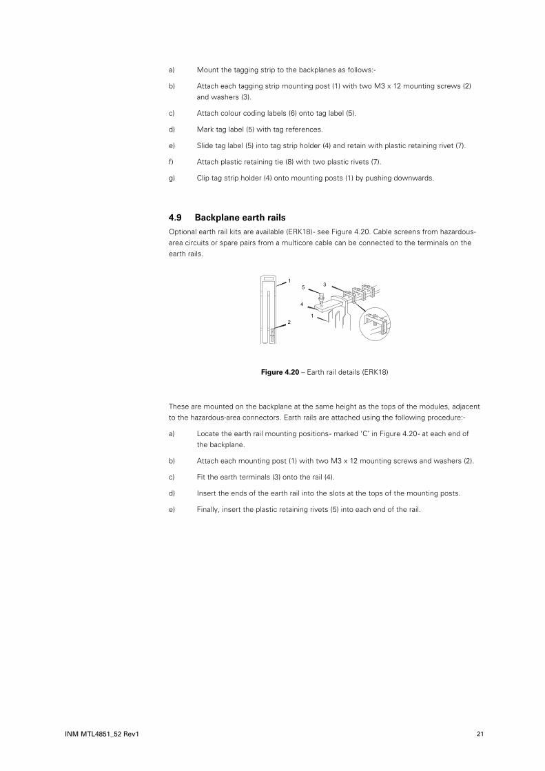
4.9 Backplane earth railsOptional earth rail kits are available (ERK18) - see Figure 4.20. Cable screens from hazardous-area circuits or spare pairs from a multicore cable can be connected to the terminals on the earth rails.
These are mounted on the backplane at the same height as the tops of the modules, adjacent to the hazardous-area connectors. Earth rails are attached using the following procedure:-
a) Locate the earth rail mounting positions - marked ‘C’ in Figure 4.20 - at each end of the backplane.
b) Attach each mounting post (1) with two M3 x 12 mounting screws and washers (2).
c) Fit the earth terminals (3) onto the rail (4).
d) Insert the ends of the earth rail into the slots at the tops of the mounting posts.
e) Finally, insert the plastic retaining rivets (5) into each end of the rail.
���
�
�
�
���
Figure 4.20 – Earth rail details (ERK18)

DRAFT - 27 November 2014DRAFT - 27 November 2014
22
DRAFT - 27 November 2014
INM MTL4851_52 Rev1
4.10 Backplanes – connections
4.10.1 Hazardous area - field wiring connections
NOTE
Personnel that carry out connection of wiring to or from hazardous areas must be correctly trained. Unless this work is done correctly, it can endanger the lives of site workers and seriously damage equipment.
Hazardous area wiring is terminated, not on the backplane but on the isolator modules, using
the blue terminals provided on them. For full information on the wiring of MTL4500 isolators
consult MTL publication INM4500.
4.10.2 Safe area - control system connections
Each channel is provided with a 2-way split-level terminal block for safe area signals. See Figure 4.21.
The numbering on the terminals corresponds to the channel number.
NOTE
The same channel terminals are used for input or output field devices because the backplane handles the necessary interconnections.
Maximum wire gauge is 2.5mm2 (12 AWG) and the wire enters from the side of the block.
4.10.3 Power supply connections
All of the CPH-SC16x (including -R) backplanes have provision for dual, redundant 24V dc power supplies. The supplies have individual, screw-terminal, plug-in connectors and two LEDs are provided on the backplane to indicate which supplies are operational. A series diode in each supply input means that the higher of the two voltage supplies is used and there is an automatic switch-over of supplies if one fails.
Connect each of the two power supply connectors to the independent supply sources according to the terminal assignments shown in Figure 4.22.
The maximum wire size is 2.5mm2 (12AWG).
Plug the connectors into the sockets on the backplanes.
The backplane has two fuses, one for each power supply. These fuses are rated at 2.5A and may be obtained as accessory FUS2.5ATE5 which contains 10 spare fuses.
Figure 4.21 – Control wiring connections – channel 3 shown
��
�
������������������ �
��������������������
Figure 4.22 – Redundant power supply wiring for backplanes

DRAFT - 27 November 2014DRAFT - 27 November 2014
INM MTL4851_52 Rev1 23
DRAFT - 27 November 2014
4.10.4 Safe area – “ring-main” power supplies
A “ring-main” system can be used to distribute power to these backplanes in a safe area. This permits individual backplanes to be taken out of service without affecting supplies to other backplanes. Two or more backplanes can be removed, provided they are neighbours, without disrupting the supply to other backplanes. Make the connections as shown in Figure 4.23, which shows ‘master’ backplanes but the same method can also be used to include ‘secondary’ backplanes.
NOTE
The ring-main option should not be used if the circuit current will exceed 12A. Wire sizes up to 2.5mm2 (12AWG) can be used and should be chosen according to current load and hence the voltage drop.
ERK18
FUS
E
PW
R2
0V0V
PWR
1
MTL
4546
Y
PWR
TSK18
PWR
1P
WR
2
D5
D2
D6
R2
R1
FS1
FS2
R3R4
D1
L454
1
PWR
MTL
4541 PW
R
RS
485
B
RS
485
AC
B
A
SW1
1
89
1016
1113
1214
15DA
TECO
DE
HAR
TAD
DR
ESS
ALA
RM 0V
0UT
2 4 8 16
MTL
4851
PWR
FAU
LT
HO
ST
HAR
T
TOP2 NEX
T
2.5A
-m
32
C B
A
FUS
E
2.5A
-m
MTL
4546
Y
PWR
MTL
4546
Y
PWR
MTL
4546
Y
PWR
MTL
4546
Y
PWR
MTL
4546
Y
PWR
MTL
4546
Y
PWR
CP
H-S
C16S -R
CP
H-S
C16M
-CC
Figure 4.23 – “Ring-main” style supply circuit for interconnecting backplanes

DRAFT - 27 November 2014DRAFT - 27 November 2014
24
DRAFT - 27 November 2014
INM MTL4851_52 Rev1
4.11 MTL customised backplanesMTL has a range of customised backplanes that accept MTL4500 Series isolators. These have been produced for various types of DCS and PLC equipment and have system connectors that suit the equipment type. Many are fitted with a DIN41651 20-way ribbon cable connector to enable the backplane to be connected to a HART maintenance system. See Appendix A or check with MTL for availability.
4.12 General cabling recommendations
4.12.1 HART signals cables
20-way HART signal ribbon cables
20-way ribbon cables are used to connect HMM64 and HMS64 backplanes with HART connection units or an IS backplane.
Connector type 20-way DIN 41651 bump polarised
Cable 0.05 inch pitch standard ribbon
Maximum length 15 metres / 50 feet *
Standard lengths of this 20-way cable are available from MTL using the part number HM64RIB20-x.x, where the x.x denotes lengths between 0.5 and 6.0 metres.
*NOTE
Cables up to the maximum length indicated above may be used, but cables exceeding 6.0 metres in length should incorporate some EMI shielding and, if used between cabinets, should be provided with additional mechanical protection in the form of rugged sheathing.
16-way HART bus ribbon cables
16-way ribbon cables are used for Master to Secondary and Secondary to Secondary backplane connections
Connector type 16-way DIN 41651 bump polarised
Cable 0.05 inch pitch standard ribbon
Length 0.5, 1.0, or 2.0 metres
Standard lengths of this 16-way cable are available from MTL using the part number HMRIB16-x.x, where the x.x denotes length.
WARNING
When the equipment is used in Zone 2 hazardous-areas, retaining clip (part number RIB-CLIP16) must be used over the 16-way connector – see below.
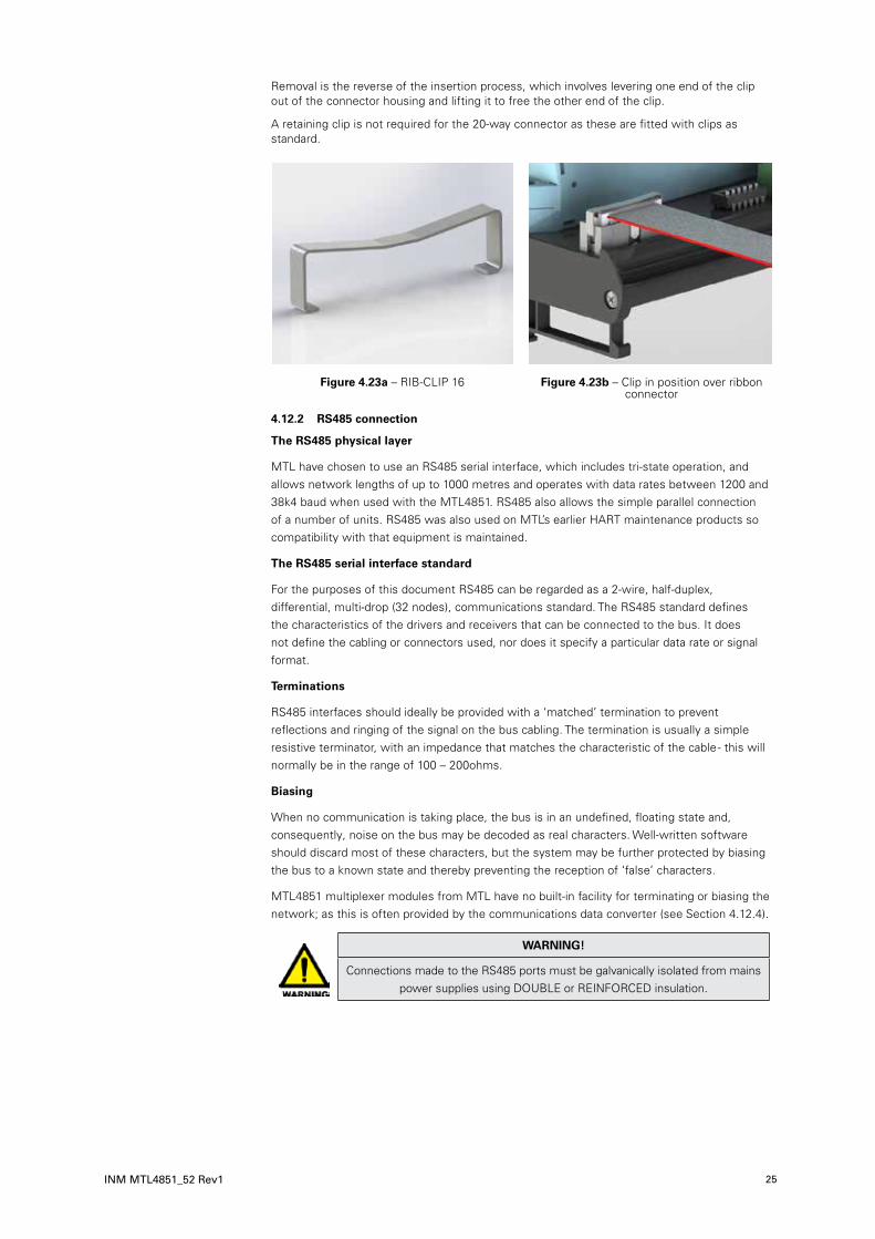
RIB-CLIP16 retaining clip
The RIB-CLIP16 retaining clip (Figure 4.23a) must be fitted over the 16-way connector (see Figure 4.23b) when the equipment is used in a Zone 2 hazardous area. This clip is required to prevent accidental disconnection of the 16-way connector while powered.
Fit one end of the clip into the connector housing – as shown in Figure 4.23b, then bend the clip until the end of it fits over the other end of the connector and press down until the clip locks into the housing on the other side. Check that both ends are securely located.
DRAFT - 27 November 2014DRAFT - 27 November 2014
INM MTL4851_52 Rev1 25
DRAFT - 27 November 2014
Removal is the reverse of the insertion process, which involves levering one end of the clip out of the connector housing and lifting it to free the other end of the clip.
A retaining clip is not required for the 20-way connector as these are fitted with clips as standard.
4.12.2 RS485 connection
The RS485 physical layer
MTL have chosen to use an RS485 serial interface, which includes tri-state operation, and allows network lengths of up to 1000 metres and operates with data rates between 1200 and 38k4 baud when used with the MTL4851. RS485 also allows the simple parallel connection of a number of units. RS485 was also used on MTL’s earlier HART maintenance products so compatibility with that equipment is maintained.
The RS485 serial interface standard
For the purposes of this document RS485 can be regarded as a 2-wire, half-duplex, differential, multi-drop (32 nodes), communications standard. The RS485 standard defines the characteristics of the drivers and receivers that can be connected to the bus. It does not define the cabling or connectors used, nor does it specify a particular data rate or signal format.
Terminations
RS485 interfaces should ideally be provided with a ‘matched’ termination to prevent reflections and ringing of the signal on the bus cabling. The termination is usually a simple resistive terminator, with an impedance that matches the characteristic of the cable - this will normally be in the range of 100 – 200ohms.
Biasing
When no communication is taking place, the bus is in an undefined, floating state and, consequently, noise on the bus may be decoded as real characters. Well-written software should discard most of these characters, but the system may be further protected by biasing the bus to a known state and thereby preventing the reception of ‘false’ characters.
MTL4851 multiplexer modules from MTL have no built-in facility for terminating or biasing the network; as this is often provided by the communications data converter (see Section 4.12.4).
WARNING!
Connections made to the RS485 ports must be galvanically isolated from mains power supplies using DOUBLE or REINFORCED insulation.
Figure 4.23a – RIB-CLIP 16 Figure 4.23b – Clip in position over ribbon connector
DRAFT - 27 November 2014DRAFT - 27 November 2014
26
DRAFT - 27 November 2014
INM MTL4851_52 Rev1
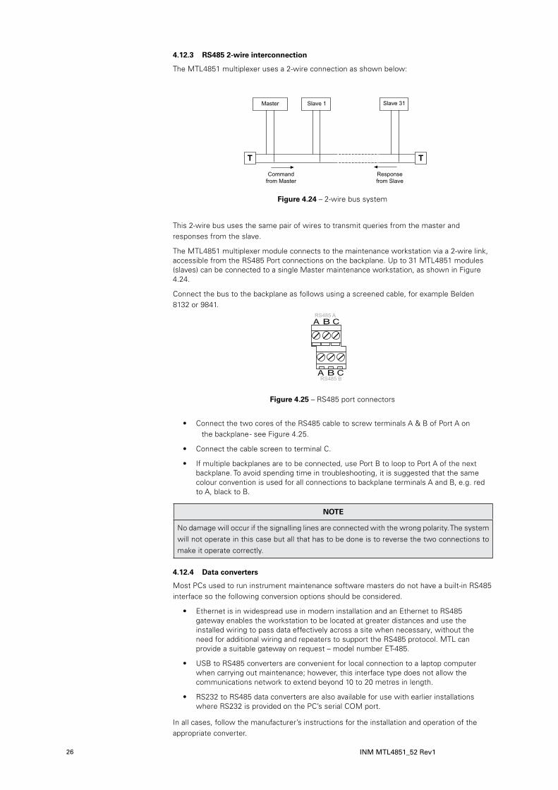
4.12.3 RS485 2-wire interconnection
The MTL4851 multiplexer uses a 2-wire connection as shown below:
This 2-wire bus uses the same pair of wires to transmit queries from the master and responses from the slave.
The MTL4851 multiplexer module connects to the maintenance workstation via a 2-wire link, accessible from the RS485 Port connections on the backplane. Up to 31 MTL4851 modules (slaves) can be connected to a single Master maintenance workstation, as shown in Figure 4.24.
Connect the bus to the backplane as follows using a screened cable, for example Belden 8132 or 9841.
• Connect the two cores of the RS485 cable to screw terminals A & B of Port A on the backplane - see Figure 4.25.
• Connect the cable screen to terminal C.
• If multiple backplanes are to be connected, use Port B to loop to Port A of the next backplane. To avoid spending time in troubleshooting, it is suggested that the same colour convention is used for all connections to backplane terminals A and B, e.g. red to A, black to B.
NOTE
No damage will occur if the signalling lines are connected with the wrong polarity. The system will not operate in this case but all that has to be done is to reverse the two connections to make it operate correctly.
4.12.4 Data converters
Most PCs used to run instrument maintenance software masters do not have a built-in RS485 interface so the following conversion options should be considered.
• Ethernet is in widespread use in modern installation and an Ethernet to RS485 gateway enables the workstation to be located at greater distances and use the installed wiring to pass data effectively across a site when necessary, without the need for additional wiring and repeaters to support the RS485 protocol. MTL can provide a suitable gateway on request – model number ET-485.
• USB to RS485 converters are convenient for local connection to a laptop computer when carrying out maintenance; however, this interface type does not allow the communications network to extend beyond 10 to 20 metres in length.
• RS232 to RS485 data converters are also available for use with earlier installations where RS232 is provided on the PC’s serial COM port.
In all cases, follow the manufacturer’s instructions for the installation and operation of the appropriate converter.
Master
Commandfrom Master
Responsefrom Slave
Slave 1 Slave 31
T T
Figure 4.24 – 2-wire bus system
Figure 4.25 – RS485 port connectors

DRAFT - 27 November 2014DRAFT - 27 November 2014
INM MTL4851_52 Rev1 27
DRAFT - 27 November 2014
5 MODULES
5.1 MTL4851/52 – installationIdentify the correct position for the multiplexer module (MTL4851 or MTL4852) on the backplane, place it over its marked connector and press it evenly and fully onto the backplane before tightening each of the two captive mounting screws (Figure 5.1). All circuit and power connections are made through the connector in the base and so it must be fully seated on the backplane.
(In the event that the module does not operate properly, the correct mounting and seating of the module should be the first point to check.)
5.2 Isolator modules (if used)If the backplane accommodates isolators, refer to instruction manual INM4500 for information on wiring hazardous-area connectors for MTL4500 Series isolators.
Position each isolator module in its appropriate location on the backplane. Ensure that the module is not tilted, which could damage the connector pins, then press it carefully to the backplane. All safe-area circuit and power connections are made through this connector.
WARNING !
Personnel that carry out connection of wiring to or from hazardous areas must be correctly trained. Unless this work is done correctly, it can endanger the lives of site workers and seriously damage equipment.
Hazardous area wiring is terminated on the isolator modules using the blue terminals provided on them. For full information on the wiring of MTL4500 isolators consult MTL publication INM4500.
5.3 Set-up and configurationVery little set-up is required for operation. For example, the speed for the RS485 interface is auto-detected within the range 38400, 19200, 9600 or 1200 baud, and requires no setting by the user.
5.3.1 HART address
Up to 31 MTL4851 multiplexer modules can be connected as a single RS485 highway. Each MTL4851 must have a unique address, which is set using the DIP switches located beside the module on the circuit board. The address switches are binary coded and the address is set by constructing the required number from the switch options provided, i.e. 1, 2, 4, 8, 16 and 32.
For example, address number 29 (16 + 8 + 4 + 1 = 29) would be set by setting the individual switches marked 1, 4, 8 and 16 to the ON position, and all others in the OFF position as shown in Figure 5.2.
Figure 5.1 – Captive mounting screw in the base of a multiplexer module
Captivemounting
screw

DRAFT - 27 November 2014
28
DRAFT - 27 November 2014 DRAFT - 27 November 2014
INM MTL4851_52 Rev1
5.3.2 Operation at power-up
The HART system is controlled by a host computer running instrument management software. Although the software is needed to operate the system, some checks can be made on the correct functioning of the hardware alone. These checks are made by observing the operation of the LEDs on top of the MTL4851.
Correct operation
At power on, the power (PWR) LED should light and the multiplexer should start to build, or rebuild, an internal scan list of the HART loops connected to it. This will be indicated by a regular flashing sequence (equal on and off duration) of the Fault LED. At the end of this process the Fault LED should go OFF to indicate that it is now in its “running” state.
Problems
If problems occurred during this power up sequence the Fault LED will either emit short and long flashes to indicate that it could not find any HART loops, or it will adopt a steady ON state to indicate that a fault was detected and the process of building the list was halted.
The MTL4851 is delivered with the default of “scanning disabled”. In either case the instrument maintenance software can be used to change the MTL4851’s scanning mode.
Scan list
During power up, or if the instrument maintenance software resets the MTL4851, a ‘scan list’ is created. This scan list will contain the identity of any loop that has a HART device connected to it. Loops can also be added individually or removed from the scan list using the ‘loop rebuild’ facility in the instrument maintenance software.
Scanning enabled
The MTL4851 scans continuously round all loops on the scan list.
6 FAULT FINDING AND ROUTINE MAINTENANCE
6.1 Fault finding procedures for MTL4851 and MTL4852 modulesBoth the HART modules are provided with LED indicators to assist the user in recognising normal operation as well as possible fault conditions.
6.1.1 MTL4851 module
The MTL4851 module is fitted with four indicator LEDs. The following table lists the operating states and provides a description of their meaning.
Figure 5.2 – Typical HART address switches set to address ‘29’
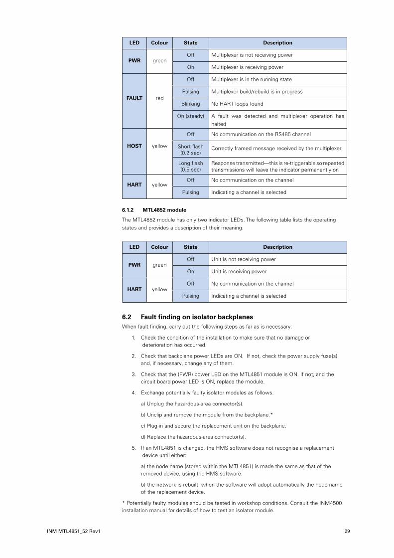
DRAFT - 27 November 2014DRAFT - 27 November 2014 DRAFT - 27 November 2014
INM MTL4851_52 Rev1 29
LED Colour State Description
PWR greenOff Multiplexer is not receiving power
On Multiplexer is receiving power
FAULT red
Off Multiplexer is in the running state
Pulsing Multiplexer build/rebuild is in progress
Blinking No HART loops found
On (steady) A fault was detected and multiplexer operation has halted
HOST yellow
Off No communication on the RS485 channel
Short flash(0.2 sec)
Correctly framed message received by the multiplexer
Long flash(0.5 sec)
Response transmitted—this is re-triggerable so repeated transmissions will leave the indicator permanently on
HART yellowOff No communication on the channel
Pulsing Indicating a channel is selected
6.1.2 MTL4852 module
The MTL4852 module has only two indicator LEDs. The following table lists the operating states and provides a description of their meaning.
LED Colour State Description
PWR greenOff Unit is not receiving power
On Unit is receiving power
HART yellowOff No communication on the channel
Pulsing Indicating a channel is selected
6.2 Fault finding on isolator backplanes When fault finding, carry out the following steps as far as is necessary:
1. Check the condition of the installation to make sure that no damage or deterioration has occurred.
2. Check that backplane power LEDs are ON. If not, check the power supply fuse(s) and, if necessary, change any of them.
3. Check that the (PWR) power LED on the MTL4851 module is ON. If not, and the circuit board power LED is ON, replace the module.
4. Exchange potentially faulty isolator modules as follows.
a) Unplug the hazardous-area connector(s).
b) Unclip and remove the module from the backplane.*
c) Plug-in and secure the replacement unit on the backplane.
d) Replace the hazardous-area connector(s).
5. If an MTL4851 is changed, the HMS software does not recognise a replacement device until either:
a) the node name (stored within the MTL4851) is made the same as that of the removed device, using the HMS software.
b) the network is rebuilt; when the software will adopt automatically the node name of the replacement device.
* Potentially faulty modules should be tested in workshop conditions. Consult the INM4500 installation manual for details of how to test an isolator module.
DRAFT - 27 November 2014
30
DRAFT - 27 November 2014 DRAFT - 27 November 2014
INM MTL4851_52 Rev1
6.3 Maintenance precautions for MTL4500 modules on backplanes
Most codes of practice permit live maintenance on intrinsically safe devices and systems, provided that precautions are taken to preserve the integrity of the device or system. During live maintenance of MTL4500 modules, the hazardous-area connectors that plug into the tops of the modules are likely to be removed, so the cables going into the hazardous-area connectors must be reasonably flexible in order to allow connectors to be inserted and removed easily from the module tops.
When a hazardous area connector is unplugged, care must be taken to ensure that it is not laid in a position where it could come into contact with the backplane or backplane components. The backplane is connected to safe-area circuits and is therefore not intrinsically safe. An unprotected connector could by-pass the essential segregation between the safe-area and hazardous-area circuits. This can be avoided by:
a) plugging the connector into an MTL4599 dummy isolator or other uninstalled MTL4500 module directly upon removal (but NOT into any other module mounted on the backplane).
b) providing some method of securing the connector temporarily so that it cannot touch the backplane or the safe-area circuits.
6.4 Routine maintenanceIt is advisable to check the general condition of the installation occasionally to make sure that no damage or deterioration has occurred. The following should be checked at least once every two years (more frequently for particularly harsh environments):
1 Modules are of the types specified in the relevant documentation and are mounted in the correct positions on the associated backplanes.
2 Modules and hazardous area connectors are correctly and legibly tagged; that the connectors are plugged into the matching modules and that the tag details given comply with the relevant documentation.
3 Modules and hazardous area connectors are securely plugged into their matching sockets.
4 All connections to the backplane, and to the hazardous area connectors, are properly made.
5 Connecting cables to backplanes and to the hazardous area connectors are of the specified type and rating. They should be correctly routed and segregated and not frayed or otherwise damaged.
6 Cable screens are properly earthed.
CAUTION
It is strongly recommended that users only undertake the tests and routine maintenance described in sections 6.1 and 6.2.
If an MTL4500 module is judged faulty, repairs or modifications MUST NOT be made as these may affect the intrinsic safety of the module. For repair or replacement, any faulty units or backplanes should be returned to MTL or the representative from which they were purchased.
7 SOFTWARE CONNECTIVITY
7.1 IntroductionThe MTL HART system provides access from a PC to the HART field devices for configuration, diagnostics and the monitoring of device performance. HART devices may be selected for regular status monitoring, and an alert issued if the status changes. An internal alarm log is also maintained which may be accessed through the Instrument Management Software (IMS) package - see Appendix B for further details.

DRAFT - 27 November 2014DRAFT - 27 November 2014 DRAFT - 27 November 2014
INM MTL4851_52 Rev1 31
In addition, MTL’s HART connection system supports dedicated software packages for valve positioners to optimise valve maintenance schedules.
7.2 Communication modesMany of the IMS packages available are based upon the use of Device Driver (DD) files or upon FDT Technology as a frame for the various communication elements.
MTL provides the software driver files to support each of these approaches.
The example below shows the integration of an MTL4851 HART Multiplexer within the Emerson AMS package applying the MTL4851 DD file.
This second example shows the deployment of the MTL4851 Comms DTM (Device Type Manager) within the Fieldcare package from Endress+Hauser and Metso that uses FDT Technology.
The MTL4851 Comms DTM enables an MTL4851 system to pass HART data to any IMS that utilises the FDT/DTM concept.
The DD and DTM files are free of charge and can be downloaded from the MTL website at:www.mtl-inst.com/product/hart_software
7.3 Software setupHaving connected the MTL4851 system, as described in this manual, set up the software as described in the software user’s manual.
Acknowedgements: Windows is a trademark of Microsoft Corporation HART is a registered trademark of HART Communication Foundation

DRAFT - 27 November 2014
32
DRAFT - 27 November 2014 DRAFT - 27 November 2014
INM MTL4851_52 Rev1
8 APPLICATIONS INVOLVING ZONE 2 HAZARDOUS AREASImportant: see the Declaration of Conformity on page ii at the front of this manual
for important additional information regarding the use of these products in countries
governed by the ATEX Directive. The following information is in accordance with the
Essential Health and Safety Requirements (Annex II) of the EU Directive 94/9/EC [the
ATEX Directive – safety of apparatus] and is provided for those locations where the ATEX
Directive is applicable.
8.1 Generala) This equipment must only be installed, operated and maintained by competent personnel. Such personnel shall have undergone training, which included instruction on the various types of protection and installation practices, the relevant rules and regulations, and on the general principles of area classification. Appropriate refresher training shall be undertaken on a regular basis. [See clause 4.2 of EN 60079-17].
b) This equipment has been designed to provide protection against all the relevant additional hazards referred to in Annex II of the directive, such as those in clause 1.2.7.
c) The MTL4851/MTL4852 and associated products mentioned in the DoC are certified as meeting the requirements of IEC/EN 60079-15 for Zone 2 applications and the European Community permits Category 3G equipment, such as these items from the MTL4850 Series, to be installed in Zone 2 flammable atmospheres provided it meets the requirements of the ATEX Directive.
8.2 Installationa) The installation must comply with the appropriate European, national and local regulations, which may include reference to the code of practice IEC/EN 60079-14. In addition, particular industries or end users may have specific requirements relating to the safety of their installations and these requirements should also be met. For the majority of installations the Directive 1999/92/EC [the ATEX Directive - safety of installations] is also applicable.
b) This apparatus may be installed in a safe area and also in a Zone 2 location providing that the relevant installation conditions are met, as given in the Special Conditions here below:
Special conditions of Safe Use for Zone 2 applications
1) The equipment must be installed in an area of not more than pollution degree 2 in accordance with IEC/EN 60664-1, and in an enclosure that provides a minimum degree of protection of at least IP54 and complies with the relevant requirements of IEC/EN 60079-0 and IEC/EN 60079-15.
2) External connections to the equipment and internal connections between the modules forming the equipment must not be inserted or removed unless either the area in which the equipment is installed is known to be non-hazardous, or the circuits connected have been de-energised.
3) The certified equipment to which the HCU16-xxx is connected must be fitted with transient protection devices meeting the requirements of clause 13 of IEC/EN 60079-15.
8.3 Inspection and maintenancea) Inspection and maintenance should be carried out in accordance with European, national and local regulations which may refer to the standard IEC/EN 60079-17. In addition specific industries or end users may have specific requirements which should also be met.
b) Access to the internal circuitry must not be made during operation.
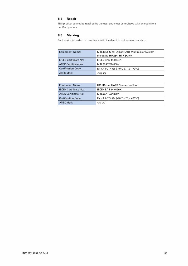
DRAFT - 27 November 2014DRAFT - 27 November 2014 DRAFT - 27 November 2014
INM MTL4851_52 Rev1 33
8.4 RepairThis product cannot be repaired by the user and must be replaced with an equivalent certified product.
8.5 MarkingEach device is marked in compliance with the directive and relevant standards.
Equipment Name: MTL4851 & MTL4852 HART Multiplexer System including HMx64, HTP-SC16x
IECEx Certificate No: IECEx BAS 14.0124X
ATEX Certificate No: MTL08ATEX4850X
Certification Code Ex nA IIC T4 Gc (-40°C ≤ Ta ≤ +70°C)
ATEX Mark II 3G
Equipment Name: HCU16-xxx HART Connection Unit
IECEx Certificate No: IECEx BAS 14.0126X
ATEX Certificate No: MTL08ATEX4850X
Certification Code Ex nA IIC T4 Gc (-40°C ≤ Ta ≤ +70°C)
ATEX Mark II 3G
DRAFT - 27 November 2014DRAFT - 27 November 2014
34
DRAFT - 27 November 2014
INM MTL4851_52 Rev1
APPENDIX A - TYPICAL COMPATIBLE SYSTEMS
MTL offer a range of backplanes for mounting MTL4500 Series IS isolators that are customized to the requirements of the particular control or shutdown system. Many of these custom boards for the analogue I/O signals include a connector for the ribbon cable connection to an HMP-HM64. Typical system examples are:
Emerson
DeltaV and DeltaV SIS s ystems
HIMA
HiMax
Honeywell
Experion C300, Safety Manager, Process Manager I/O systems
Invensys
Foxboro FBM systems, Triconex Tricon & Trident systems
Siemens
ET200M
Yokogawa
Centum R3, Prosafe RS systems
Contact MTL with details of your specific requirements.
APPENDIX B - ALARM EVENT LOG
The multiplexer maintains a log of alarm events that may read using the Instrument Management Software. The types of event that might appear can be grouped into the following categories:
• General information
• Multiplexer internal parameters or values
• Diagnostic errors causing reset
The possible event log messages are listed below by category, and the meaning or appropriate action is supplied beside them.

DRAFT - 27 November 2014DRAFT - 27 November 2014
INM MTL4851_52 Rev1 35
DRAFT - 27 November 2014
General logs Meaning or required action
!Alarm generated by HART test command 242 MTL diagnostic test activated
!No storage space for transmitter Memory full of field device data
!Found a pre Rev 5 HART transmitter Check manufacturer for update
!Other master detected on loop Secondary master present
!Alarm Clear input used to reset alarms
Download of bootloader started Firmware update in progress
Bootloader download complete, module will restart Firmware update completed
Debug mode. No CRC installed in flash memory
Reset due to Watchdog or Brownout See list of causes below
Module Powered Up
Module failed watchdog test Return to MTL if alarm persists.
Warm start - Event Log or status corrupt
Unknown reason for module reset
Logs followed by a value: Meaning or required action
!Duplicate Transmitter Unique Id. ID used on loop Check manufacturer for update
!+12V Supply out of range Check power supply to multiplexer is within specification.
Return to MTL if alarm persists.
!-12V Supply out of range Return to MTL if alarm persists.
!VBias out of range Return to MTL if alarm persists.
!VLeak out of range Return to MTL if alarm persists.
Power up scan complete - Transmitters found = Number, 0-32
Logs followed by 2 values: Meaning or required action
!VH signal out of range Check power supply to multiplexer is within specification.
Return to MTL if alarm persists.
Log messages following an error thatcaused the module to reset
Meaning or required action
!CRC error in RAM copy of serial number Return to MTL if alarm persists.
!CRC error in RAM image of configuration parameters Return to MTL if alarm persists.
!An internal watchdog reset occurred Return to MTL if alarm persists.
!A clock monitor reset occurred Return to MTL if alarm persists.
!Module restarted due to failure in Startup Ram test Return to MTL if alarm persists.
!Background RAM word test failed Return to MTL if alarm persists.
!Background Ram byte test failed Return to MTL if alarm persists.
!Background Ram block test failed Return to MTL if alarm persists.
!Cold start flash test failed Return to MTL if alarm persists.
!Incremental flash test failed Return to MTL if alarm persists.
!Incremental flash test switch variable corrupt Return to MTL if alarm persists.
!Illegal instruction trap did not execute Return to MTL if alarm persists.
!Stack overflowed Return to MTL if alarm persists.
!Stack underflowed Return to MTL if alarm persists.
nued|

DRAFT - 27 November 2014DRAFT - 27 November 2014
36
DRAFT - 27 November 2014
INM MTL4851_52 Rev1
Log messages following an error thatcaused the module to reset
Meaning or required action
!Background diagnostics not running Return to MTL if alarm persists.
!RAM test not running Return to MTL if alarm persists.
!Bad call to diagnostic monitor Return to MTL if alarm persists.
!RAM test copy address corrupted Return to MTL if alarm persists.
!RAM corruption of TQ data in diag Return to MTL if alarm persists.
!Incremental CPU test failed Return to MTL if alarm persists.
Diagnostic session counter corrupted Return to MTL if alarm persists.
!EEPROM Group1 CRC error Return to MTL if alarm persists.
!EEPROM Group2 CRC error Return to MTL if alarm persists.
!RAM corruption in TQ data in EHS Return to MTL if alarm persists.
!An unused interrupt has occurred Return to MTL if alarm persists.
!PLL out of lock Return to MTL if alarm persists.
!An illegal instruction has been encountered Return to MTL if alarm persists.
!Cold start CPU test failed Return to MTL if alarm persists.
!Bad call to program monitor Return to MTL if alarm persists.
!Stack pointer corrupted Return to MTL if alarm persists.
!Sequence error: Main initialisation Return to MTL if alarm persists.
!Sequence error: Main startup Return to MTL if alarm persists.
!Sequence error: First Field I/O Return to MTL if alarm persists.
!Sequence error: Timer Queue Return to MTL if alarm persists.
!Sequence error: Second Field I/O Return to MTL if alarm persists.
!Sequence error: Event handler Return to MTL if alarm persists.
!Sequence error: Diagnostic processing Return to MTL if alarm persists.
!Module state corrupted Return to MTL if alarm persists.
!RAM corruption of TQ data in main Return to MTL if alarm persists.
!The 1ms timer ISR executed late Return to MTL if alarm persists.
The 1ms timer ISR executed early Return to MTL if alarm persists.
!Program monitor failed to report Return to MTL if alarm persists.
!Diagnostic monitor failed to report Return to MTL if alarm persists.
!Cancelled timer can’t be found Return to MTL if alarm persists.
!TQ Run out of sequence Return to MTL if alarm persists.
Single or occasional occurrence of these events may be due to noise or interruptions of the power supply, but multiple or frequent events might indicate problems with the installation, or with the module, in which case it should be returned to MTL for investigation.
continued from page 33

DRAFT - 27 November 2014DRAFT - 27 November 2014
INM MTL4851_52 Rev1 37
DRAFT - 27 November 2014
APPENDIX C COMPATABILITY WITH EARLIER MTL4840 SYSTEM
The MTL4851 and MTL4852 HART modules described in this manual are a later generation of HART instrument maintenance equipment based upon the earlier and very popular MTL4840 system, which is in widespread use today.
The new MTL4851 system is a development that builds upon the success of its predecessor and incorporates many of the features introduced by the newer 32-channel MTL4850 multiplexer. It offers a number of benefits that were outlined at the beginning of this manual, including greater operating speed; compatibility with later versions of HART devices, e.g. Rev. 5, 6 and 7; simpler setting-up procedure using fewer parameter definitions; together with the additional benefit of lower installation cost as well as a lower cost per channel.
Obtaining these benefits has involved a number of changes being necessary to boards, operating busses, data structures, etc. This means that the older generation of MTL4841 and MTL4842 modules are not plug-compatible with the latest models. Also different backplanes have had to be designed to obtain the benefits that the newer modules offer. The backplane changes have resulted in significant simplification in the interconnection wiring of backplanes where, in most cases, there is a reduced need for power wiring as the d.c. power is now incorporated in the bus wiring.
All these changes mean that the original MTL4840 modules and associated hardware and backplanes cannot be interchanged at module or board level.
Compatibility is maintained however at sub-system level where MTL4851 system equipment can be installed alongside existing MTL4840 equipment, and where they may then share the same RS485 bus, controlled simultaneously by the same management software.
For example, an existing installation of MTL4840 equipment could be expanded using the latest MTL4851/52 equipment, where each new ‘master’ backplane is given the next available HART address. The new MTL4851/52 equipment may then be connected to more recent HART devices running revision 5, 6 or 7, to allow them to be integrated into the existing system architecture.
MTL4841 MTL4841 MTL4850 MTL4850 MTL4851
Ethernetnetwork
ET485MTL4842
CONN4
D6 D5
MTL4842
CONN1
DATECODE
LABEL
SYSCONN. IDENTRS485 PORT1
A
MTL4842
CONN2
MTL4842
CONN3
1234
BPHM64
D1
D2
P1
R2 R1
P2
PWR2
PWR1
P3P4
D3
D4
RS485 PORT2
BCABC
Luto
n. En
glan
dM
easurem
ent Tech
no
log
y Ltd
MTL4841
CONN5
P6
FUSE
P5
0VPWR
1PWR
2
FS1
SYSCONN. IDENT
DATEH
MP
-HM
64
P4P3
P2P1
BA
BC
A
RS485
C
12
RS485 ARS485 B
ON
CODE
FUSE
FUSE
D5
SW1
2 8 32
D2D4
D6
R2
D3R1
D1
SKT 1
FS1
FS2
R3
R4
0VPW
R2
PWR
1
0.5A-m
0.5A-m
CH1-32CH33-64
CH
1-16
CH
17-32
CH
49-64
CH
33-48
PWR1
PWR2
4 16
HARTADDRESS
Ch1-
Ch1+
Tx1+Tx2+
Ch2-
Ch2+Tx2+
Ch2+
Ch2-Ch1-
Ch1+
Tx1+
1
11
15
13
9
7
5
3
HMU16
P1
SystemField
2
12
16
14
10
8
6
4
C
P1 P2
RS48
5
C
MTL
4841
MTL
4842
CONN
2
POW
ER
MTL
4842
AB
RS48
5
AB
SystemFieldA ABB1234567891011121314151616
123456789101112131415
A BB A
-P250
ON
17181920212223242526272829303132
17181920212223242526272829303132
-S150-S200-S240
D2
R1
FS1FUSE
0.5A-m
R3
R4 FS2FUSE
0.5A-m
D1
D5
R2
D6
HART SW1
2 8 321 4 16
SYSCONN. ID
ENT
RS485 BRS485 A
0V
PW
R1
1
PW
R2
C
ADDRESS
DATECODE
B
A
C
B
A
PWR2
0V0V
12
PO
WE
R0V
OU
T
ALA
RM
A
RS
485 A
BB
C
HA
RT
AD
DR
ES
S
14
162
832
NE
XT
!O
N
4 3 2 1
P4 P3 P2 P1
DAT
EC
OD
ELA
BE
L
SY
SC
ON
N. I
DE
NT
C
PR
EV
IOU
S
HMM64HMS64-CC
O N
PC terminal
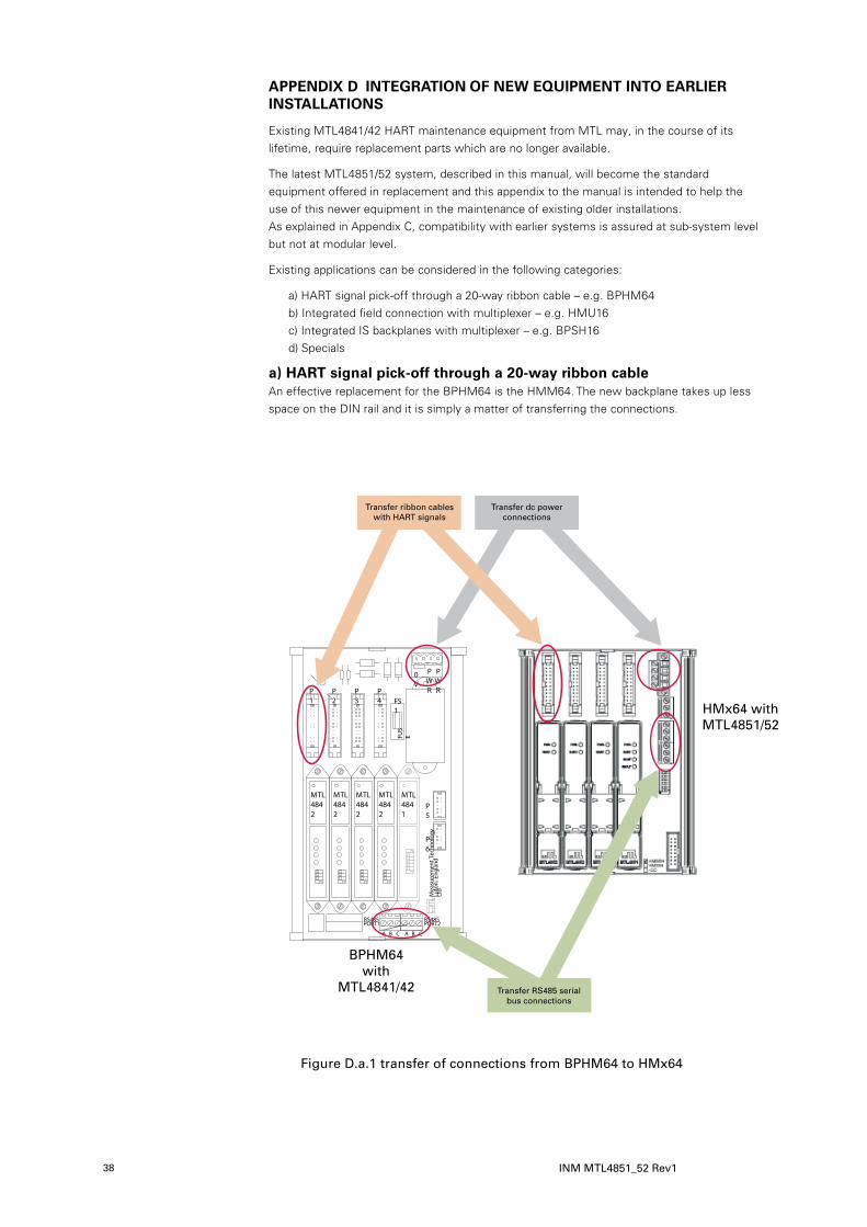
DRAFT - 27 November 2014DRAFT - 27 November 2014
38
DRAFT - 27 November 2014
INM MTL4851_52 Rev1
APPENDIX D INTEGRATION OF NEW EQUIPMENT INTO EARLIER INSTALLATIONS
Existing MTL4841/42 HART maintenance equipment from MTL may, in the course of its lifetime, require replacement parts which are no longer available.
The latest MTL4851/52 system, described in this manual, will become the standard equipment offered in replacement and this appendix to the manual is intended to help the use of this newer equipment in the maintenance of existing older installations. As explained in Appendix C, compatibility with earlier systems is assured at sub-system level but not at modular level.
Existing applications can be considered in the following categories:
a) HART signal pick-off through a 20-way ribbon cable – e.g. BPHM64 b) Integrated field connection with multiplexer – e.g. HMU16 c) Integrated IS backplanes with multiplexer – e.g. BPSH16 d) Specials
a) HART signal pick-off through a 20-way ribbon cable An effective replacement for the BPHM64 is the HMM64. The new backplane takes up less space on the DIN rail and it is simply a matter of transferring the connections.
FUS
E
FS1
MTL4842
MTL4842
MTL4842
MTL4842
RS485
BA B C A
Luto
n. E
ngla
ndM
easu
rem
ent T
echn
olog
y Lt
d
RS485
C
P1
P2
P3
P4
P5
P6
MTL4841
0V
PWR
PWR
PORT1 PORT2
Transfer ribbon cables with HART signals
Transfer ribbon cableswith HART signals
Transfer dc powerconnections
Transfer RS485 serialbus connections
BPHM64with
MTL4841/42
HMx64 withMTL4851/52
Figure D.a.1 transfer of connections from BPHM64 to HMx64
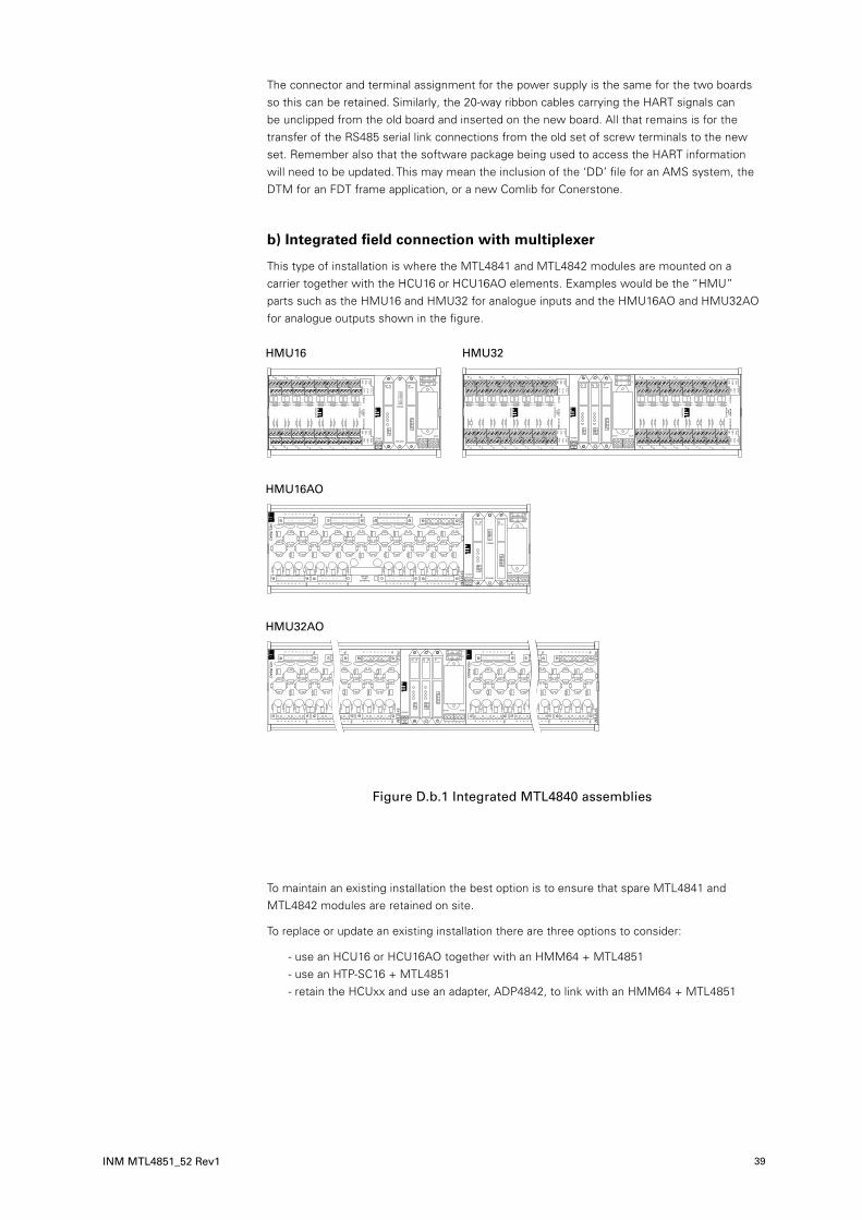
DRAFT - 27 November 2014DRAFT - 27 November 2014
INM MTL4851_52 Rev1 39
DRAFT - 27 November 2014
The connector and terminal assignment for the power supply is the same for the two boards so this can be retained. Similarly, the 20-way ribbon cables carrying the HART signals can be unclipped from the old board and inserted on the new board. All that remains is for the transfer of the RS485 serial link connections from the old set of screw terminals to the new set. Remember also that the software package being used to access the HART information will need to be updated. This may mean the inclusion of the ‘DD’ file for an AMS system, the DTM for an FDT frame application, or a new Comlib for Conerstone.
b) Integrated field connection with multiplexer
This type of installation is where the MTL4841 and MTL4842 modules are mounted on a carrier together with the HCU16 or HCU16AO elements. Examples would be the “HMU” parts such as the HMU16 and HMU32 for analogue inputs and the HMU16AO and HMU32AO for analogue outputs shown in the figure.
Figure D.b.1 Integrated MTL4840 assemblies
To maintain an existing installation the best option is to ensure that spare MTL4841 and MTL4842 modules are retained on site.
To replace or update an existing installation there are three options to consider:
- use an HCU16 or HCU16AO together with an HMM64 + MTL4851 - use an HTP-SC16 + MTL4851 - retain the HCUxx and use an adapter, ADP4842, to link with an HMM64 + MTL4851
HMU16 HMU32
HMU16AO
HMU32AO

DRAFT - 27 November 2014DRAFT - 27 November 2014
40
DRAFT - 27 November 2014
INM MTL4851_52 Rev1
The space on the DIN rail occupied by these solutions is different, but it may be practical to mount the HMM64 carrier to serve a number of HMU assemblies being replaced within a cabinet, connected by 20-way ribbon cables.
The alternative HTP-SC16 is smaller but does not offer the same connection arrangement for the field and system signals. On the HCU16 boards three terminals are available for each channel whereas on the HTP-SC16 only two terminals per channel are provided. Swapping the HMU16 for an HTP-SC16 may be an attractive option but this is only possible if the signal connectivity provided by the latter item is suitable for the application. Check each requirement carefully and refer to MTL for advice if needed.
Remember that the application software will need to be updated to include support for the MTL4851.
c) Integrated IS backplanes with multiplexer and Specials
Each of these installations needs to be considered individually.
The majority of existing integrated IS applications will be using isolators from the MTL4000 range and the opportunity should be taken to update this interface equipment to the current MTL4500 family.
Maintenance of the HART multiplexer parts of existing installations is likely to be best implemented through continued use of the MTL4841/42 spare parts that the user should have already purchased. There is little point in attempting to upgrade just the multiplexer since the remaining lifetime of the rest of the installation is going to be short. One possible solution is to use the ADP4842 adapter in place of the MTL4842 to connect the HART signals to a supplementary multiplexer board using either the MTL4850 or MTL4851 equipment.
Figure D.c.1 ADP4842 adapter

DRAFT - 27 November 2014DRAFT - 27 November 2014
INM MTL4851_52 Rev1 41
DRAFT - 27 November 2014
THIS PAGE IS LEFT INTENTIONALLY BLANK

DRAFT - 27 November 2014DRAFT - 27 November 2014
EUROPE (EMEA):
+44 (0)1582 723633 [email protected]
THE AMERICAS:
+1 800 835 7075 [email protected]
ASIA-PACIFIC:
+65 6 645 9888 [email protected]
The given data is only intended as a product description and should not be regarded as a legal warranty of properties or guarantee. In the interest of further technical developments, we reserve the right to make design changes.
Measurement Technology Limited, Great Marlings, Butterfield, LutonBeds, LU2 8DL, UK.Tel: + 44 (0)1582 723633 Fax: + 44 (0)1582 422283E-mail: [email protected]
© 2015 MTL All Rights ReservedPublication No. INM MTL4851_52 Rev1March 2015
AUSTRALIAMTL Instruments Pty Ltd,205-209 Woodpark Road, Smithfield,New South Wales 2164, AustraliaTel: + 61 1300 308 374 Fax: + 61 1300 308 463
E-mail: [email protected]
CHINACooper Electric (Shanghai) Co. Ltd955 Shengli Road, Heqing Industrial ParkPudong New Area, Shanghai 201201Tel: + 86 21 2899 3817 Fax: + 86 21 2899 3992
E-mail: [email protected]
FRANCEMTL Instruments sarl,7 rue des Rosiéristes, 69410 Champagne au Mont d’OrFranceTel: + 33 (0)4 37 46 16 70 Fax: +33 (0)4 37 46 17 20
E-mail: [email protected]
GERMANYMTL Instruments GmbH,Heinrich-Hertz-Str. 12, 50170 Kerpen, GermanyTel: + 49 (0)22 73 98 12 - 0 Fax: + 49 (0)22 73 98 12 - 2 00
E-mail: [email protected]
INDIAMTL India,No.36, Nehru Street, Off Old Mahabalipuram RoadSholinganallur, Chennai - 600 119, IndiaTel: + 91 (0) 44 24501660 /24501857 Fax: + 91 (0) 44 24501463
E-mail: [email protected]
ITALYMTL Italia srl,Via A. Meucci, 10, I-20094 Corsico (MI), ItalyTel: + 39 (0)2 61802011 Fax: + 39 (0)2 61294560
E-mail: [email protected]
JAPANCooper Crouse-Hinds Japan KK,MT Building 3F, 2-7-5 Shiba Daimon, Minato-ku,Tokyo, Japan 105-0012Tel: + 81 (0)3 6430 3128 Fax: + 81 (0)3 6430 3129
E-mail: [email protected]
BeNeLuxMTL Instruments BVTerheijdenseweg 465, 4825 BK BredaThe NetherlandsTel: +31 (0) 76 7505360 Fax: +31 (0) 76 7505370
E-mail: [email protected]
NORWAYNorex ASFekjan 7c, Postboks 147,N-1378 Nesbru, NorwayTel: +47 66 77 43 80 Fax: +47 66 84 55 33
E-mail: [email protected]
SINGAPORECooper Crouse-Hinds Pte LtdNo 2 Serangoon North Avenue 5, #06-01 Fu Yu BuildingSingapore 554911Tel: + 65 6 645 9888 Fax: + 65 6 487 7997
E-mail: [email protected]
SOUTH KOREACooper Crouse-Hinds Korea12F, Vision Tower, 707-2 Yeoksam-Dong Gangnam-Gu,Seoul 135-080, South Korea.Tel: +82 2 538 3481 Fax: +82 2 538 3505
E-mail: [email protected]
UNITED ARAB EMIRATESCooper Industries/Eaton CorporationOffice 205/206, 2nd Floor SJ Towers, off. Old Airport Road,Abu Dhabi, United Arab EmiratesTel: +971 2 44 66 840 Fax: +971 2 44 66 841
E-mail: [email protected]
UNITED KINGDOMMeasurement Technology Limited,Great Marlings, Butterfield, LutonBeds LU2 8DLTel: + 44 (0)1582 723633 Fax: + 44 (0)1582 422283
E-mail: [email protected]
AMERICASCooper Crouse-Hinds MTL Inc.3413 N. Sam Houston Parkway W.Suite 210, Houston TX 77086, USATel: + 1 281-571-8065 Fax: + 1 281-571-8069
E-mail: [email protected]