HARRISTON PICK POTATO PLANTER...5 SAFETY. YOU are responsible for the operation and SAFE maintenance...
83
HARRISTON PICK POTATO PLANTER Dickey John/Ground Drive
Transcript of HARRISTON PICK POTATO PLANTER...5 SAFETY. YOU are responsible for the operation and SAFE maintenance...
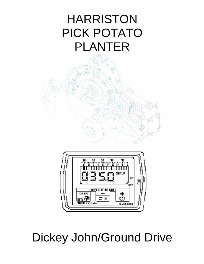
HARRISTON
PICK POTATO
PLANTER
Dickey John/Ground Drive


To set the Controller, follow this procedure: a. Turn Console on. Console should momentarily display application rate, then display “0.0” . NOTE: If the display shows OFF, then place the OFF/AUTO/FLUSH switch to the OFF position. b. Enter SETUP Mode by pressing and holding the Oper/Setup button until Setup appears (flashing) in the upper right corner of the display. c. The setup pointer will be under the “A” and the left most digit will flash. d. The “+“ (Plus) button is used to change the value of the digit that is flashing. e. When required number is displayed, press the “-” (Minus) button to move to the next digit. f. Press the “+” (Plus) button again to set second number. g. Repeat procedure until all digits are set/ h. Press and hold the “-“ (Minus) button to sequence the decimal point. When the decimal point is not shown on the display, the 4 digits comprise a whole number. Decimal must be in correct position shown in all constant settings. i. Confirm or adjust all constant settings by pressing the Oper/Setup button to sequence to each setup position (A-I). g. Exit the Setup mode by pressing and holding the Oper/Setup button until “0.0” is displayed. Seed spacing change is now complete and controller is ready for use.
Setup Pos. Setting A ---------- Seed Spacing 32” Rows=2.67 B 0.2 34” Rows=2.85 C ------------------- --------------- 36” Rows=3.00 D 1.728 38” Rows=3.16 E --------------- 48.00 40” Rows=3.33 F 1.5 G ---------------- 4.50 H .75 I Ground Speed Calibration (See Page 11 in DJ Manual)
Setup Pos.A Seed Spacing 165.07 1 82.54 2 55.02 3 41.27 4 33.01 5 27.51 6 23.58 7 20.63 8 18.34 9 16.51 10 15.01 11 13.76 12 12.70 13 11.79 14 11.01 15 10.32 16 09.71 17 09.17 18 08.69 19 08.25 20 For plant population, find the seed spacing desired. Enter into setup position (A) a plant population in 1000th. Example: 12 inch seed spacing. Find 13756 plants per acre. Enter 13.76 into the CCS100

Console Constant Settings A: Seed spacing: (See seed chart)
B: Application Rate +/-: .25 (This number must be entered but is normally not used in planter operation)
C: Row Spacing (entered in feet, not inches). Number is the same regardless of the number of rows.
32” Row Spacing = 2.67 feet
34” Row Spacing = 2.85 feet 36” Row Spacing = 3.00 feet 38” Row Spacing = 3.16 feet 40” Row Spacing = 3.33 feet D: Density: This is the average density of potato seed (always set at 1.728).
E: Spreader Constant: This is the number of digits on application rate sensor per pick arm per row (always 48.0).
F: Flush Flow Rate: This is the speed the planter will run with the OFF/AUTO/FLUSH switch held in “FLUSH” position. Set in a range from 1 to 2.5 (normal setting is 1.500).
G: Bargraph: This number indicates the speed of the Application Rate sensor. Set within a range of 4.00-6.00 (normal setting is 4.500)
H: System Response: This number determines how fast the planter will respond to the tractor hydraulics. Start with a setting between 0.650 to 0.750. If planter surges when starting or changing speed, reduce number by 0.100 until planter runs smooth. Never set higher than 0.750 on planters.
I: Radar calibration number: Speed calibration number. Normal setting is 6096. To refine this number, see page 11 in the Dickey John Manual. Radar scope must be set at 35° from horizontal to read accurately!
Helpful Hints/Troubleshooting
If the tractor has not moved for 60 seconds, the monitor will shut off.
Start the flow control valve at the #3 setting.
Start the hydraulic speed control (rabbit and turtle) on the tractor at just under half speed. if there is not enough oil, the monitor will flash “APER”.
If the Monitor is turned on with the flush in the auto position and it does not work properly, check the 3 Point safety switch.
Always connect the power source directly to the battery.
The frame should be level and set high enough so the parallel linkage is lower in back by 1 to 3 inches.
Keep the potato level in the bowl as low as possible.
Clear the potatoes away from the switch at the end of the day.
If seed pieces are planted too shallow, reduce speed and/or check gauge wheel depth.
18 RPM on the picker wheels has been shown to have the best consistency.
Do not use the hydraulic system to operate other equipment.
If all feeds do not run, this does not indicate an electrical problem.
Horizontal

Table of Contents on Following Page

1
TABLE OF CONTENTS Index on Page 76
SECTION DESCRIPTION PAGE
1 Introduction ...................................................................... 3 2 Safety ................................................................................ 4 2.1 General Safety .......................................................................... 4 2.2 Operating Safety ....................................................................... 6 2.3 Maintenance Safety ................................................................... 6 2.4 Chemical Safety ........................................................................ 7 2.5 Hydraulic safety ......................................................................... 8 2.6 Transport Safety ........................................................................ 8 2.7 Storage Safety .......................................................................... 9 2.8 Tire Safety ................................................................................. 9 2.9 Assembly Safety ....................................................................... 9 2.10 Safety Decals ............................................................................ 9 2.11 Sign-Off Form .......................................................................... 10 3 Safety Decal Locations ................................................. 11 4 Operation ........................................................................ 17 4.1 To the New Operator or Owner ............................................... 17 4.2 Principle Components ............................................................. 18 4.3 Pre-Start and Break-In ............................................................ 19 4.4 Pre-Operation Checklist .......................................................... 19 4.5 Equipment Matching ................................................................ 20 4.6 Dickey John Hydraulic Control System .................................... 21 4.7 Dickey John Components ........................................................ 21 4.8 Dickey John Console Calibration ............................................. 22 4.9 Attaching Tractor ..................................................................... 24 4.10 Daily Inspection ....................................................................... 25 4.11 Machine Settings ..................................................................... 26 4.11.1 Gauge Wheels ........................................................................ 26 4.11.2 Picker Wheel/Seed Bowl Clearance ........................................ 26 4.11.3 Pick Placement in Pick Arms ................................................... 27 4.11.4 Picker Wheel Cam ................................................................... 28 4.11.5 Feedbox Chain Speed ............................................................. 29 4.11.6 Planter Shoe Depth Rear ........................................................ 29 4.11.7 Closing Disc Adjustments ........................................................ 29 4.11.8 Seed Bowl Volume .................................................................. 30 4.11.9 Field Operation ........................................................................ 32 4.12 Operating Hints ....................................................................... 34 4.13 Transporting ............................................................................ 35 4.14 Storage ................................................................................... 36 4.11.1 Placing in Storage ................................................................... 36 4.11.2 Removing from Storage........................................................... 38

2
SECTION DESCRIPTION ............................................. PAGE 5 Service And Maintenance ............................................. 39 5.1 Service .................................................................................... 39 5.1.1 Fluids and Lubricants ........................................................................... 39 5.1.2 Greasing............................................................................................... 39 5.1.3 Service Intervals .................................................................................. 41 5.2 Maintenance ............................................................................ 44 5.2.1 Picker Wheel Drive Sprocket ............................................................... 44 5.2.2 Picker Wheel to Seed Bowl Clearance ................................................ 45 5.2.3 Re-Timing Picker Wheels .................................................................... 45 5.2.4 Row Unit Shear Bolts ........................................................................... 46 5.2.5 Hydraulics ............................................................................................ 46 5.2.6 Roller Chain Tension ........................................................................... 46 5.2.7 Hydraulic Drive Chain .......................................................................... 46 5.2.8 Picker Wheel Drive Chain .................................................................... 47 5.2.9 Feedbox Roller Chain Drive ................................................................. 47 5.2.10 Feed Chain Tension ............................................................................. 47 5.2.11 Operation of Feedbox Motor ................................................................ 48 5.2.12 Feedbox Motor Testing ........................................................................ 49 5.2.13 Replacing Bowl Switch ......................................................................... 50 5.2.14 Rebuilding Shoes ................................................................................. 50 5.2.15 Walking Beam/Tracking Adjustment .................................................... 51 6 Optional Equipment ....................................................... 53 6.1 Row Markers ........................................................................................ 53 6.2 Hill Rollers ............................................................................................ 53 6.3 Deer Tong Ripper Shank ..................................................................... 54 6.4 Trash Shank ......................................................................................... 54 6.5 Rear Ripper .......................................................................................... 54 6.6 Pesticide Applicator ............................................................................. 55 6.7 Mechanical Fertilizer Attachment ......................................................... 55 Fertilizer Rate Charts ........................................................................... 57 Ground Drive Seed Spacing Chart ...................................................... 61 7 Troubleshooting ............................................................ 63 7.1 Machine Troubleshooting..................................................................... 63 7.2 Control System Troubleshooting ......................................................... 66 8 Shipping And Assembly ............................................... 73 9 Specifications ................................................................ 74 9.1 Bolt Torque.............................................................................. 74 9.2 Hydraulic Fitting Torque .......................................................... 74 9.3 Mechanical .............................................................................. 75 10 Index ............................................................................... 76

3
1 INTRODUCTION Congratulations on your choice of a Harriston potato planter to complement your farming operation. This equipment has been designed and manufactured to meet the needs of a discerning potato industry for the efficient planting of potatoes. Safe, efficient, and trouble-free operation of your Harriston planter requires that you and anyone else who will be operating or maintaining the planter read and understand all of the safety, operation, maintenance, and trouble shooting information contained in this Operator's Manual. This manual covers the 2, 4, 6, and 8 row models. Differences are covered and explained where appropriate. Keep this manual handy for frequent reference and to pass on to new operators and owners. Call your Harriston dealer or distributor if you need assistance, information, or additional copies of the manual.
OPERATOR ORIENTATION - The directions left, right, front, and rear, as mentioned throughout the manual, are as seen from the driver's seat and facing in the direction of travel
Serial # 40YYXX YY = Year of ManufactureModel #4004 (4 Row Pull-Type) #4006 (6 Row Pull-Type) #4008 (8 Row Pull-Type) #4014 (4 Row Semi-Mount) #4016 (6 Row Semi-Mount)

4
2 SAFETY
SAFETY ALERT SYMBOL This Safety Alert symbol means ATTENTION! BECOME ALERT! YOUR SAFETY IS INVOLVED!
3 Big Reasons SIGNAL WORDS: Note the use of the signal words DANGER, WARNING, AND CAUTION with the safety messages. The appropriate signal word for each message has been selected using the following guidelines:
The Safety Alert symbol identifies important safety messages on the Harriston Planter and in the manual. When you see this symbol, be alert to the possibility of personal injury or death. Follow the instructions in the safety message.
Accidents Disable and Kill Accidents Cost Accidents Can Be Avoided DANGER - An immediate and specific hazard, which WILL result in severe personal injury or death if the proper precautions are not taken. WARNING - A specific hazard or unsafe practice, which COULD result in severe personal injury or death if proper precautions are not taken. CAUTION - Unsafe practices which could result in personal injury if proper practices are not taken, or as a reminder of good safety
Why is SAFETY Important to you?

5
SAFETY
YOU are responsible for the SAFE operation and maintenance of your Harriston Potato Planter. YOU must ensure that you and anyone else who is going to operate, maintain, or work around the Planter be familiar with the operating and maintenance procedures and related SAFETY information contained in this manual. This manual will take you step-by-step through your working day and alerts you to all good safety practices that should be adhered to while operating the planter. Remember, YOU are the key to safety. Good safety practices not only protect you but also the people around you. Make these practices a working part of your safety program. Be certain that EVERYONE operating this equipment is familiar with the recommended operating and maintenance procedures and follows all the safety precautions. Most accidents can be prevented. Do not risk injury by ignoring good safety practices. Planter owners must give operating instructions to operators or employees before allowing them to operate the planter, and at least annually thereafter per OSHA (Occupational Safety and Health Administration) regulation 1928.57. The most important safety device on this equipment is a SAFE operator. It is the operator's responsibility to read and understand ALL safety and operating instructions in the manual and to follow them. Most accidents can be avoided. A person who has not read and understood all operating and safety instructions is not qualified to operate the machine. An untrained operator exposes himself and bystanders to possible serious injury or death. Do not modify the equipment in any way. Unauthorized modification may impair the function and/or safety and could affect the life of the equipment. Think SAFETY! Work SAFELY!
2.1 GENERAL SAFETY
1. Read and understand the Operator's Manual and all safety signs before operating, maintaining, or adjusting the planter. 2. Provide a first-aid kit for use in case of an accident. Store in a highly visible place. 3. Provide a fire extinguisher for use in case of an accident. Store in a highly visible place. 4. Wear appropriate protective gear. This list includes, but is not limited to: A hard hat Protective shoes with slip resistant soles Protective glasses or goggles Heavy gloves Wet weather gear Hearing protection Respirator or filter mask 5. Install and secure all guards before starting. 6. Do not allow riders. 7. Wear suitable ear protection for prolonged exposure to excessive noise. 8. Stop tractor engine, lower machine to the ground, place all controls in neutral, set park brake, remove ignition key, and wait for all moving parts to stop before servicing, adjusting, repairing, or unplugging. 9. Clear the area of people, especially small children, before starting the unit. 10. Review safety related items annually with all personnel who will be operating or maintaining the planter.

6
2.2 OPERATING SAFETY
1. Read and understand the Operator's Manual and all safety signs before operating, servicing, adjusting, repairing, unplugging, or filling. 2. Do not allow riders. 3. Install and secure all guards and shields before starting or operating. 4. Keep hands, feet, hair, and clothing away from moving parts. 5. Stop tractor engine, lower machine to the ground, place all controls in neutral, set park brake, remove ignition key, and wait for all moving parts to stop before servicing, adjusting, repairing, unplugging, or filling. 6. Place all tractor controls in neutral before starting. 7. Operate machine only while seated on the tractor seat. 8. Clear the area of bystanders, especially small children, before starting. 9. Keep all hydraulic lines, fittings, and couplers tight and free of leaks before using. 10. Clean reflectors, slow moving vehicle sign, and lights before transporting. 11. Add extra lights and use pilot vehicle when transporting during times of limited visibility. 12. Use hazard flashers on tractor when transporting. 13. Install safety chain when attaching to tractor. 14. Follow chemical manufacturers' handling and safety instructions exactly when using chemicals with machine. 15. Review safety instructions with all operators annually.
2.3 MAINTENANCE SAFETY
1. Follow all the operating, maintenance, and safety information in the manual. 2. Support the machine with blocks or safety stands when changing tires or working beneath it. 3. Stop tractor engine, lower machine to the ground, place all controls in neutral, set park brake, remove ignition key, and wait for all moving parts to stop before servicing, adjusting, repairing, unplugging, or filling. 4. Make sure all guards are in place and properly secured when maintenance work is completed. 5. Never wear ill-fitting, baggy, or frayed clothing when working around or on any of the drive system components. 6. Before applying pressure to a hydraulic system, make sure all lines, fittings, and couplers are tight and in good condition. 7. Install safety rod and pin securely in position on hitch cylinder frame before working under frame. 8. Relieve pressure from hydraulic circuit before servicing or disconnecting from tractor. 9. Keep hands, feet, hair, and clothing away from moving or rotating parts. 10. Clear the area of bystanders, especially small children, when carrying out any maintenance and repairs or making adjustments. 11. Wear appropriate protective gear when contacting chemical handling components on machine.

7
2.4 CHEMICAL SAFETY
1. Some agricultural chemicals are among the most toxic substances known to man. Minute quantities can contaminate clothing, machinery, the workplace, and the environment. Follow the chemical manufacturers' instructions exactly. Death can result from their improper use. 2. Misuse, including excessive rates, uneven application, and label violations, can cause injury to crops, livestock, people, and the environment. 3. Do not breathe, touch, or ingest chemicals or the dust. Always wear protective clothing and follow safe handling procedures. 4. Follow the manufacturers' instructions for chemical storage. Avoid unnecessary storage by purchasing only the quantity needed for the crop year. 5. Keep all chemicals out of the reach of children and away from livestock and animals. 6. Store chemicals only in their original containers in a locked area. 7. Check with local authorities regarding the disposal of small quantities of chemicals, chemical containers and wash water. 8. Do not burn the containers or leave them lying in the field or ditches. Take them to your local container disposal site. 9. Wash thoroughly before eating. Use detergent to remove all chemical residue. Rinse carefully and dry with disposable towels.
10. Do not eat in the field where chemicals are being applied. 11. In case of chemical poisoning, get immediate medical attention. 12. Know the Poison Control Emergency telephone number for your area before using agricultural chemicals. United States – 1-800-222-1222 Alberta – 1-800-332-1414 Manitoba – (204)-787-2591 Ottawa – 1-800-267-1373 13. Thoroughly wash clothing and equipment contaminated by chemicals. 14. Wash the applicators immediately after field work. Dispose of wash water in an environmentally safe manner. Wash water can contaminate the soil or a clean water supply.

8
2.5 HYDRAULIC SAFETY
1. Make sure that all components in the hydraulic system are kept in good condition and are clean. 2. Replace any worn, cut, abraded, flattened, or crimped hoses and metal lines. 3. Do not attempt any makeshift repairs to the hydraulic lines, fittings, or hoses by using tape clamps, or cements. The hydraulic system operates under extremely high pressure. Such repairs will fail suddenly and create a hazardous and unsafe condition. 4. Wear proper hand and eye protection when searching for a high-pressure hydraulic leak. Use a piece of wood or cardboard as a backstop instead of hands to isolate and identify a leak. 5. If injured by a concentrated high-pressure stream of hydraulic fluid, seek medical attention immediately. Serious infection or toxic reaction can develop from hydraulic fluid piercing the skin surface. 6. Before applying pressure to the system, make sure all components are tight and that lines, hoses, and couplings are not damaged.
2.6 TRANSPORT SAFETY
1. Make sure you are in compliance with all local regulations regarding transporting equipment on public roads and highways. 2. Make sure the SMV (Slow Moving Vehicle) emblem and all the lights and reflectors that are required by the local highway and transport authorities are in place, are clean, and can be seen clearly by all overtaking and oncoming traffic. 3. Do not allow anyone to ride on the Planter or tractor during transport. 4. Do not exceed 32 km/h (20 mph). Reduce speed on rough roads and surfaces. 5. Do not transport with a full seed or fertilizer tank.

9
2.7 STORAGE SAFETY
1. Store away from areas of human activity. Do not permit children to play on or around the stored machine. 2. Make sure the unit is sitting, or blocked up firm and solid and will not tip or sink into a soft area. 3. Cover with a weather - proof tarpaulin and tie down securely. 2.8 TIRE SAFETY
1. Failure to follow proper procedures when mounting a tire on a wheel or rim can produce an explosion, which may result in serious injury or death. 2. Do not attempt to mount a tire unless you have the proper equipment and experience to do the job. 3. Have a qualified tire dealer or repair service perform required tire maintenance. 2.9 ASSEMBLY SAFETY
1. Assemble in an area with sufficient space to handle the largest component and access to all sides of machine. 2. Use only lifts, cranes, jacks, and tools, with sufficient capacity for the load. 3. Use two people to handle the large bulky components. 4. Do not allow spectators in the working area.
2.10 SAFETY DECALS
1. Keep safety decals and signs clean and legible at all times. 2. Replace safety decals and signs that are missing or have become illegible. 3. Replaced parts that displayed a safety sign should also display the current sign. 4. Safety decals or signs are available from your Dealer Parts Department. HOW TO INSTALL SAFETY DECALS:
1. Be sure that the installation area is clean and dry. 2. Decide on the exact position before you remove the backing paper. 3. Remove the smallest portion of the split backing paper. 4. Align the decal over the specified area and carefully press the small portion with the exposed sticky backing in place. 5. Slowly peel back the remaining paper and carefully smooth the remaining portion of the decal in place. 6. Small air pockets can be pierced with a pin and smoothed out using the piece of decal backing paper.

10
2.11 SIGN-OFF FORM Harriston Industries follows the general Safety Standards specified by the American Society of Agricultural Engineers (ASAE) and the Occupational Safety and Health Administration (OSHA). Anyone who will be operating and/or maintaining the Potato Planter must read and clearly understand ALL Safety, Operating, and Maintenance information presented in this manual. Do not operate or allow anyone else to operate this equipment until such information has been reviewed. Annually review this information before the season start-up. Make these periodic reviews of Safety and Operation a standard practice for all of your equipment. We feel that an untrained operator is unqualified to operate this machine. A sign-off sheet is provided for your record keeping to show that all personnel who will be working with the equipment have read and understand the information in the Operator's Manual and have been instructed in the operation of the equipment.
SIGN OFF FORM
Date Employees Signature Employers Signature

11
3 SAFETY DECAL LOCATIONS

12
3 SAFETY DECAL LOCATIONS
The types of decals and locations on the equipment are shown in the illustration below. Good safety requires that you familiarize yourself with the various Safety Decals, the type of warning and the area, or particular function related to that area, that requires your SAFETY AWARENESS.5
1. Read Operator's Manual before using machine. 2. Stop tractor engine, lower machine to the ground place all controls in neutral, set park brake, remove ignition key, and wait for all moving parts to stop before servicing, adjusting, repairing, unplugging, or filling. 3. Install and secure all guards before starting. 4. Keep hands, feet, hair and clothing away from moving parts. 5. Do not allow riders. 6. Keep all hydraulic lines, fittings, and couplers tight and free of leaks before using. 7. Clean reflectors, SMV, and lights before transporting. 8. Install safety rod and pin securely in position on hitch cylinder frame before working under frame or transporting machine.
9. Add extra lights and use pilot vehicle when transporting during items of limited visibility.
10. Use hazard flashers on tractor when transporting.
11. Install safety chain when attaching to tractor.
12. Follow chemical manufacturers' handling and safety instructions exactly when using chemicals with machine.
13. Review safety instructions with all operators
1
11
REMEMBER - If Safety Decals have been damaged, removed, become illegible, or parts replaced without decals, new decals must be applied. New decals are available from your authorized dealer.

13
SAFETY DECAL LOCATIONS

14
The types of decals and locations on the equipment are shown in the illustration below. Good safety requires that you familiarize yourself with the various Safety Decals, the type of warning, and the area, or particular function related to that area, that requires your SAFETY AWARENESS 8 15
16
REMEMBER - If Safety Decals have been damaged, removed, become illegible, or parts replaced without decals, new decals must be applied. New decals are available from your authorized dealer.

15
SAFETY DECAL LOCATIONS

16
13
6 12
1 093006 Warning Falling Hazard 2 080021 Decal Yellow Reflector 3 080020 Decal Red Reflector 4 093057 Decal Harriston Large 5 093001 Decal Caution (Hitch) 6 093052 Decal Attention Check Torque 7 093056 Decal Made with Pride 8 093003 Decal Missing Shield 9 093055 Decal Harriston Quality 10 093058 Decal Slow Moving Sign 11 093005 Decal Warning High Pressure 12 093020 Attention Alteration to Hydraulic 13 093016 Decal Warning Falling Hazard Small 14 093009 Serial Number Plate 15 093004 Danger Toxic Chemical 16 093018 Warning – Empty Seed Tank for Transport 17 093044 Warning – Moving Parts Hazard 18 093019 Warning – Rotating Parts Hazard
17
4 OPERATION
1. Read and understand the Operator's Manual and all safety signs before operating, servicing, adjusting, repairing, unplugging, or filling. 2. Do not allow riders. 3. Install and secure all guards and shields before starting or operating. 4. Keep hands, feet, hair, and clothing away from moving parts. 5. Stop tractor engine, lower machine to the ground, place all controls in neutral, set park brake, remove ignition key, and wait for all moving parts to stop before servicing, adjusting, repairing, unplugging, or filling. 6. Place all tractor controls in neutral before starting. 7. Operate machine only while seated on the tractor seat. 8. Clear the area of bystanders, especially small children, before starting. 9. Keep all hydraulic lines, fittings, and couplers tight and free of leaks before using. 10. Clean reflectors, SMV, and lights before transporting. 11. Add extra lights and use pilot vehicle when transporting during times of limited visibility. 12. Use hazard flashers on tractor when transporting. 13. Install safety chain when attaching to tractor. 14. Follow chemical manufacturers' handling and safety instructions exactly when using chemicals with machine. 15. Review safety instructions with all operators annually.
4.1 TO THE NEW OPERATOR OR OWNER
Harriston potato planters are designed to quickly and efficiently plant potatoes with almost any row spacing and in a variety of seed placement spacings. The ground or hydraulic drive ensures accurate placement of seed at any reasonable speed. Many features incorporated into this machine are the result of suggestions made by customers like you. Read this manual carefully to learn how to operate the machine safely and to set it to provide maximum field efficiency. By following the operating instructions in conjunction with a good maintenance program, your planter will provide many years of trouble-free service.

18
4.2 PRINCIPLE COMPONENTS The Harriston potato planter uses a large hopper (A) to carry cut potatoes over the field for planting. A small hydraulically powered feed chain (B) moves the seed into the seed bowl (C) next to the planting wheels (D). An electrical switch in the bowl activates the potato chain when more seed is required. Ground driven tires or a hydraulic system drive the planting wheels through a series of adjustable chains and sprockets used to set the spacing between each plant. A series of spring-loaded picks (E) select a potato as it moves through the bowl. As the picker wheels (D) turn, the picks are pulled back when they contact a cam on the lower portion of the arc. The potato is released and drops into the ground. The shoe (G) ahead of the planting wheel opens the ground to receive the seed. Discs (I), behind the row unit, close the seedbed and start the hilling process. Adjustable gauge wheels (G) allow the operator to set the depth of the seed.
Before starting to work, all operators should familiarize themselves with the location and function of the controls on the planter and tractor. The Harriston Planter is offered with four different drive systems: Raven 662 Hydraulic, Raven 760 Hydraulic, Dickey-John CCS100, and Ground (Mechanical)
ALL ELECTRICAL CONNECTIONS MUST BE MADE DIRECTLY TO THE BATTERY WITH 'CLEAN' LEADS. GROUND WIRE MUST BE FREE FROM CORROSION
ANY SYSTEM MALFUNCTIONS CAUSED BY CONNECTION OF ELECTRICAL LEADS TO ANY
OTHER POWER SOURCE WILL NOT BE COVERED BY HARRISTON INDUSTRIES

19
4.3 PRE-START AND BREAK IN Although there are no operational restrictions on the Planter when it is used for the first time, it is recommended that the following mechanical items be checked. PRE-START INSPECTION 1. Read the Operator's Manual
2. 2. Tighten wheel bolts to 140 ft-lbs (24 N.m) torque
3. 3. Check that tires are inflated to their specified pressure.
4. 4. Check that the hydraulic lines and electrical harness are routed where they will not contact moving parts. Be sure all components are clipped, taped, or tied securely in place.
5. 5. Check that all guards are installed and secured.
6. 6. Tighten all mounting bolts on rear ladder and loading platform if so equipped.
7. 7. Check that all picks are in place and straight. Install or straighten as required.
8. 8. Rotate each picker wheel to be sure that the overrunning clutch and drives are functioning properly. Lubricate or adjust as required.
9. 9. Check that all required nuts and bolts are installed and tightened to their specified torque.
10. 10. Lubricate the machine.
AFTER OPERATING FOR 2 HOURS 1. Re-torque all wheel bolts.
2. Check tire pressure.
3. Re-torque all other fasteners and hardware.
4. Check that no hoses are being pinched, crimped, or are rubbing. Reroute as required.
5. Check that the wiring harness is not being pinched, crimped, or rubbing. Reroute as required.
6. Check the tension and alignment of all drive and feed chains. Adjust as required.
7. Check the condition of the picks on each wheel. Replace or straighten as required.
8. Lubricate the machine.
AFTER OPERATING FOR 10 HOURS 1. Re-torque all wheel bolts.
2. Re-torque all fasteners and hardware.
3. Check the routing of hydraulic lines and the wiring harness. Reroute as required to prevent pinching, crimping, binding or rubbing.
4. Check the tension and alignment of all drive and conveyor chains. Adjust as required.
5. Check the condition of the picks on each wheel. Replace or straighten as required.
6. Go to the normal Service and Maintenance schedule.
RE-TORQUE WHEEL BOLTS EVERY 50 HOURS. 4.4 PRE OPERATION CHECKLIST Efficient and safe operation of the Harriston planter requires that each operator reads and understands the operating procedures and all related safety precautions outlined in this section. A pre-operation checklist is provided for the operator. It is important for both personal safety and maintaining the good mechanical condition of the machine that this checklist is followed. Before operating the Planter and each time thereafter, the following areas should be checked: 1. Lubricate the machine per the schedule outlined
in the Maintenance Section.
2. Check the drives for entangled material.
3. Check that the picks are not broken or bent. Replace or straighten as required.
4. Check the chains and sprockets for proper tension and alignment. Adjust as required.
5. Ensure that all bearings turn freely.
6. Make sure all guards and shields are in place secured, and functioning as designed.
7. Check that all hydraulic fittings and connections are tight and in good condition.

20
4.5 EQUIPMENT MATCHING The Harriston potato planter was designed to be used on large 2-wheel drive or front wheel assist agricultural tractors. To ensure good field performance, the following list of specifications must be met.: HYDRAULICS The towing tractor must be capable of 12 gpm @ 2000 p.s.i. to operate hydraulic drive. Additional flow must be provided for the following: Ground Drive (4 gallons) Rear Lift (3 gallons) Markers (2 gallons) Fertilizer (5 gallons) Hydraulic Drive (12 gallons) Air Insecticide (4 gallons) THREE POINT HITCH With 2 point semi-mount attaching systems, a Cat III 3 point is recommended. HORSEPOWER Machine Level Rolling Size Firm Soil 2 Row 60 HP 100 HP
Soft Soil
4 Row 125 HP 170 HP 6 Row 150 HP 180 HP 8 Row 180 HP 200 HP TIRE CONFIGURATION It is recommended that a tire width be used on the tractor that will allow the tire footprint to fit between the rows being planted. The row spacing of the Planter can be adjusted. Tires that are too wide for the available space will compact the seedbed and affect plant growth.
TRACTOR WEIGHT By following the recommendations for tractor power, the tractor will have sufficient weight to provide stability for the unit during field operations or transporting. It is also recommended that each tractor be equipped with a full complement of suitcase weights on the front of the tractor. This will provide the required weight on the front for turning as well as extra traction if equipped with front wheel assist. ELECTRICAL Each machine requires a 12 volt 20 amp power supply to operate the solenoid for the feed chain into the seed bowl. An additional 12 volt 5 amp supply is required for the hydraulic drive models. The switch is routed into the cab for easy access during operation

21
4.6 CONTROL SYSTEM Before starting to work, all operators should familiarize themselves with the location and function of the controls on the electrical boxes and the tractor. GROUND DRIVE MODEL A switch on an electrical box is routed into the cab to control the feed chain system. The switch needs to be ON for the feed system to operate. When the switch is OFF, the feed system will stop. DICKEY JOHN HYDRAULIC DRIVE MODEL The hydraulic drive model is equipped with a switch on an electrical box that is routed into the cab for operating the feed chains the same as for the ground drive.
4.7 HYDRAULIC DRIVE COMPONENTS:
NOTE: A valve in the circuit automatically turns the hydraulic system OFF if the machine has not moved for 40 seconds. This feature prevents inadvertent operation if the circuit isn’t turned OFF when stopping for at least 40 seconds
An electrically operatedsolenoid valve to meterhydraulic oil to the motorthat drives the picker wheels
A radar gun mountedon the rear frame tomeasure machine movementand ground speed
An electrical control box that is routed into thecab to operate the system. The box takes thesignal from the radar unit to determine the amountof oil for the motor to produce a known planting rate
ROTATING PART HAZARD When inspecting or servicing the planter, disengage hydraulic system by shutting off tractor to prevent accidental engagement of hydraulics as a result of motion detected by the radar scope.
22
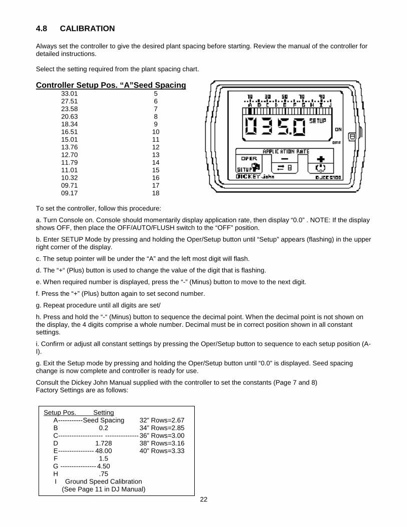
4.8 CALIBRATION Always set the controller to give the desired plant spacing before starting. Review the manual of the controller for detailed instructions. Select the setting required from the plant spacing chart.
33.01 5 Controller Setup Pos. “A”Seed Spacing
27.51 6 23.58 7 20.63 8 18.34 9 16.51 10 15.01 11 13.76 12 12.70 13 11.79 14 11.01 15 10.32 16 09.71 17 09.17 18 To set the controller, follow this procedure:
a. Turn Console on. Console should momentarily display application rate, then display “0.0” . NOTE: If the display shows OFF, then place the OFF/AUTO/FLUSH switch to the “OFF” position.
b. Enter SETUP Mode by pressing and holding the Oper/Setup button until “Setup” appears (flashing) in the upper right corner of the display.
c. The setup pointer will be under the “A” and the left most digit will flash.
d. The “+“ (Plus) button is used to change the value of the digit that is flashing.
e. When required number is displayed, press the “-” (Minus) button to move to the next digit.
f. Press the “+” (Plus) button again to set second number.
g. Repeat procedure until all digits are set/
h. Press and hold the “-“ (Minus) button to sequence the decimal point. When the decimal point is not shown on the display, the 4 digits comprise a whole number. Decimal must be in correct position shown in all constant settings.
i. Confirm or adjust all constant settings by pressing the Oper/Setup button to sequence to each setup position (A-I).
g. Exit the Setup mode by pressing and holding the Oper/Setup button until “0.0” is displayed. Seed spacing change is now complete and controller is ready for use.
Consult the Dickey John Manual supplied with the controller to set the constants (Page 7 and 8) Factory Settings are as follows:
Setup Pos. Setting A ----------- Seed Spacing 32” Rows=2.67 B 0.2 34” Rows=2.85 C -------------------- --------------- 36” Rows=3.00 D 1.728 38” Rows=3.16 E ---------------- 48.00 40” Rows=3.33 F 1.5 G ---------------- 4.50 H .75 I Ground Speed Calibration (See Page 11 in DJ Manual)

23
Console Constant Settings
A: Seed spacing: (see seed chart)
B: Application Rate +/-: .25 (This number must be entered but is normally not used in planter operation)
C: Row Spacing (entered in feet, not inches) Number is the same regardless of the number of rows
32” Row Spacing = 2.67 feet
34” Row Spacing = 2.85 feet 36” Row Spacing = 3.00 feet 38” Row Spacing = 3.16 feet 40” Row Spacing = 3.33 feet D: Density: This is the average density of potato seed (always set at 1.728).
E: Spreader Constant: This is the number of digits on application rate sensor per pick arm per row (always 48.0).
F: Flush Flow Rate: This is the speed the planter will run with the OFF/AUTO/FLUSH switch held in “FLUSH” position. Set in a range from 1 to 2.5 (Normal setting is 1.500)
G: Bargraph: This number indicates the speed of the Application Rate sensor. Set within a range of 4.00-6.00 (Normal setting is 4.500)
H: System Response: This number determines how fast the planter will respond to the tractor hydraulics. Start with a setting between 0.650 to 0.750. If planter surges when starting or changing speed, reduce number by 0.100 until planter runs smooth. Never set higher than 0.750 on planters.
I: Radar calibration number: Speed calibration number. Normal setting is 6096. To refine this number, see page 11 in the Dickey John Manual. Radar scope must be set at 35° from horizontal to read accurately!
Horizontal
24
4.9 ATTACHING TRACTOR When hooking the Planter to a tractor, follow this procedure: 1. Clear the area of bystanders, especially small children. 2. Make sure there is enough room and clearance from obstacles to safely back up to the Planter. 3. Back up slowly and align the link arms as required for your machine. 4. Two point attachment with Quick Hitch. a. Align the claws on the Quick Hitch slightly below the mounting pins on the Planter. b. Back up until the pins on the Planter are above the claws. c. Raise the 3-point hitch until the pins seat in the claws. d. Be sure the retainers are released to hold the pins in the claws. e. Adjust the turnbuckle on the top link to position the Quick Hitch vertically when the lower lift arms are horizontal. f. Set the 3-point hitch in the non-sway position g. Set the lower links on the tractor in the free float position.
IF YOUR TRACTOR IS NOT EQUIPPED WITH A QUICK HITCH, IT WILL BE NECESSARY TO INSTALL THE MOUNTING PINS THROUGH EACH BALL ON THE 3 POINT HITCH. BE SURE TO INSTALL THE RETAINER ON EACH PIN.
5. Connect the other hydraulic circuits. 6. Route the electrical switch box and control console into the cab. Route the electrical cord over the hitch and secure in position with clips, tape, or plastic ties. Be sure the wire doesn't dangle and contact the ground or become pinched. Allow enough slack for turning. 7. Start the tractor and raise the machine. 8. Remove pin from frame stands. Raise stand into storage position and re-pin. 9. Raise and lower machine a couple of times to be sure everything is secured, tight, and functioning. 10. Check rear lift wheels for function and operation.
25
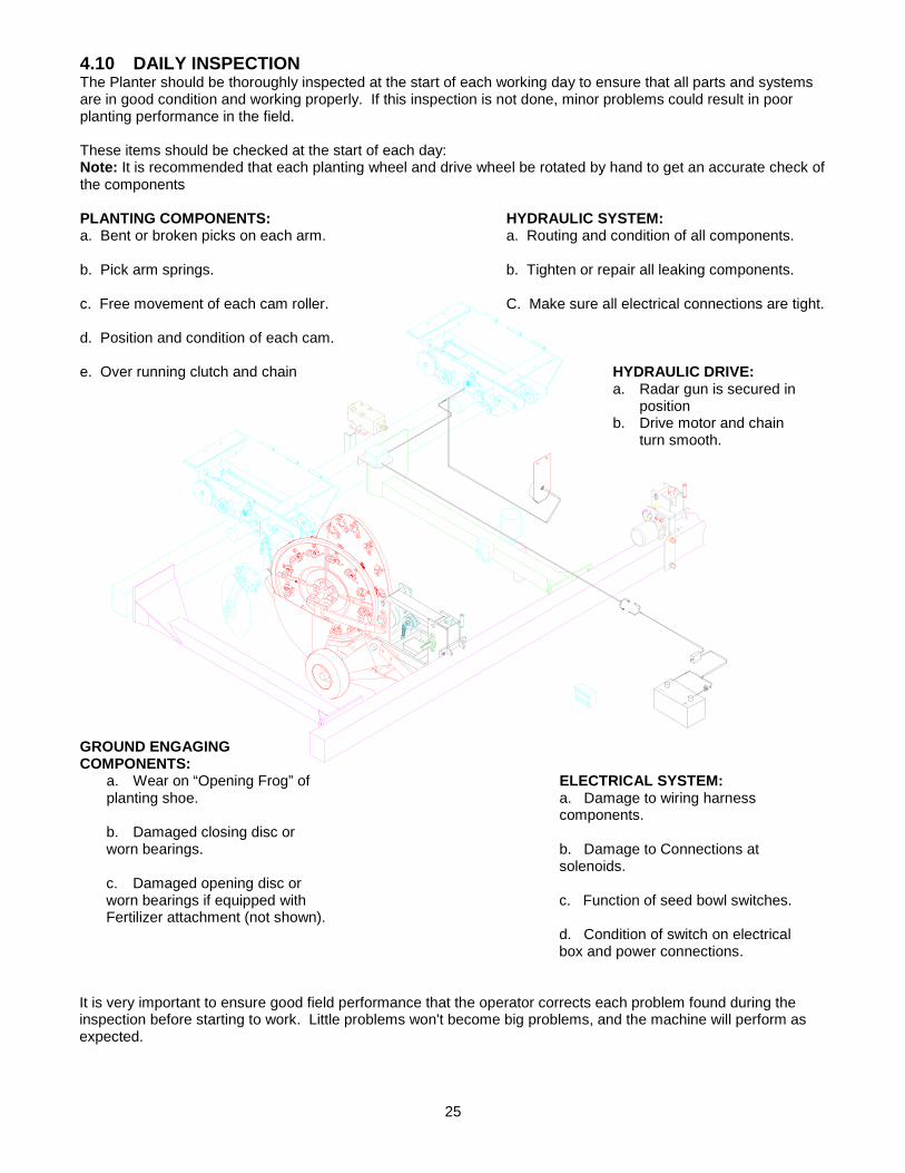
4.10 DAILY INSPECTION The Planter should be thoroughly inspected at the start of each working day to ensure that all parts and systems are in good condition and working properly. If this inspection is not done, minor problems could result in poor planting performance in the field. These items should be checked at the start of each day: Note: It is recommended that each planting wheel and drive wheel be rotated by hand to get an accurate check of the components PLANTING COMPONENTS: HYDRAULIC SYSTEM: a. Bent or broken picks on each arm. a. Routing and condition of all components. b. Pick arm springs. b. Tighten or repair all leaking components. c. Free movement of each cam roller. C. Make sure all electrical connections are tight. d. Position and condition of each cam. e. Over running clutch and chain HYDRAULIC DRIVE:
a. Radar gun is secured in position
b. Drive motor and chain turn smooth.
GROUND ENGAGING COMPONENTS:
a. Wear on “Opening Frog” of ELECTRICAL SYSTEM: planting shoe. a. Damage to wiring harness components. b. Damaged closing disc or worn bearings. b. Damage to Connections at solenoids. c. Damaged opening disc or worn bearings if equipped with c. Function of seed bowl switches. Fertilizer attachment (not shown).
d. Condition of switch on electrical box and power connections. It is very important to ensure good field performance that the operator corrects each problem found during the inspection before starting to work. Little problems won't become big problems, and the machine will perform as expected.

26
4.11 MACHINE SETTINGS During the machine inspection that the operator should do at the start of each working day, it is his responsibility to check each machine setting to ensure that they are appropriately set for the operating conditions. The following adjustments should be checked: 4.11.1 Gauge Wheels
Each row is equipped with a set of gauge wheels to control planting depth. The two gauge wheels carry part of the weight of the planting shoe as the machine moves through the field. All irregular seedbed conditions are evened out by the wheels. A variety of holes are provided to adjust gauge wheels.
The height of the gauge wheels are set by the adjusting cranks on the front of the row unit frame. Turn clockwise to raise and counter-clockwise to lower. Repeat with other gauge wheel assemblies. Always operate all gauge wheels at the same depth. The gauge wheels are also adjustable on the gauge wheel itself. Adjust here as needed, to avoid having adjusting cranks to low. 4.11.2 Picker Wheel/Seed Bowl Clearance Clearance is provided between the picker wheel and the seed bowl to: a. Allow self-cleaning: dirt, sprouts, and seed piece slivers can fall out to prevent plugging. b. Allow seed piece alignment for good pick centering and penetration. When the seed pieces fill the gap, the picks will be approximately centered in the piece. c. Provide increasing clearance as the seed moves up the tapered gap. This minimizes drag on the seed piece that can cause the piece to fall off the picks. d. Prevent contact between the seed bowl and picker wheel that would result in mechanical damage to either component. See page 45 for instructions on setting clearance.

27
4.11.3 PICK PLACEMENT IN PICK ARMS
Each pick arm is equipped with 3 or 4 holes for pick mounting. The holes provide different pick placement for different seed sizes and shapes. Although any pick placement can be used if it works, the following table should be used as a guide when starting. Seed Condition Number of Picks Average size seed. Normal Position. 2 1 and 3
Pick Placement
Factory placement 2 5 and 6 Small seed with few or no large pieces 2 1 and 2 Large average seed 2 1 & 4 or 3 & 4 Very Large Seed. Wet seed that has 4 1, 2, and 3 or difficulty staying on picks 1, 2, and 4 or 1,3, and 4
13
24
Small Seed(Too many doubles)
Factory placement(Recommended)
Large or Wet Seed(early drop)
Large or Wet Seed(early drop)

28
4.11.4 PICKER WHEEL CAM Each picker wheel is equipped with a cam mounted on the machine frame that contacts the spring loaded pick plate release arm. The cam is located on the lower segment of the picker wheel arc. As the picker wheel rotates, the pick plate release arm roller should contact the cam at the 3:30 position (viewed from the right side of the machine). This cam contact point will withdraw picks from the strike plate, retract the picks from the seed, and drop the seed behind the shoe for planting. The cam should not move the pick arm so far that a space is opened between the ends of the picks and the strike plate. A gap can allow other material to get in and prevent the arm from snapping closed when capturing the next seed. A large gap between the stripper plate and the pick can cause unnecessary wear and fatigue on the pick arm. The cam must release the arm at the 6:30 position to allow the picks to stab the next potato as the pick components move through the seed bowl. It is very important that the cam and roller are aligned to give a dynamic release and insertion action by the picks. Each pick assembly must have a spring to provide the force to close the pick arm and push the picks into the next seed. PICKER WHEEL CAM ADJUSTMENT As the picker wheel turns, the roller on the end of the pick arms contacts the stationary cam on the bottom of its arc. The cam should contact the rollers at the 3:30 position and release it at the 7:30 position (viewed from the right side of machine). The cam should be aligned to make full contact with each pick arm roller as the picker wheel rotates. When the roller contacts the cam, the pick arm pivots to withdraw the picks through the holes in the striker plate. No gap should be left between the striker plate and the ends of the picks. To adjust the cam for alignment with the roller and pick arm movement, follow this procedure:
1. Loosen the cam mounting bolts on the front and bottom of the cam.
2. Adjust cam to the required position.
3. Rotate the picker wheel to check roller alignment and
pick arm movement on each pick assembly.
4. Tighten the mounting bolts to their specified torque levels.
29
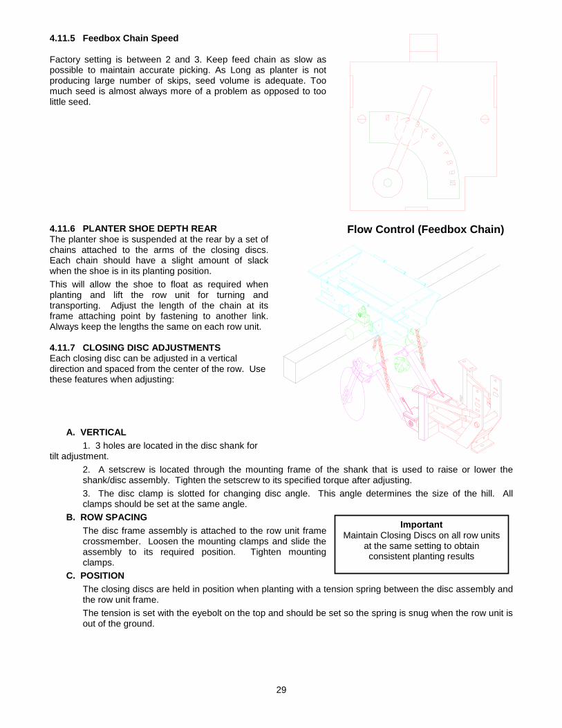
4.11.5 Feedbox Chain Speed Factory setting is between 2 and 3. Keep feed chain as slow as possible to maintain accurate picking. As Long as planter is not producing large number of skips, seed volume is adequate. Too much seed is almost always more of a problem as opposed to too little seed. 4.11.6 PLANTER SHOE DEPTH REAR The planter shoe is suspended at the rear by a set of chains attached to the arms of the closing discs. Each chain should have a slight amount of slack when the shoe is in its planting position. This will allow the shoe to float as required when planting and lift the row unit for turning and transporting. Adjust the length of the chain at its frame attaching point by fastening to another link. Always keep the lengths the same on each row unit. 4.11.7 CLOSING DISC ADJUSTMENTS Each closing disc can be adjusted in a vertical direction and spaced from the center of the row. Use these features when adjusting:
A. VERTICAL 1. 3 holes are located in the disc shank for tilt adjustment. 2. A setscrew is located through the mounting frame of the shank that is used to raise or lower the
shank/disc assembly. Tighten the setscrew to its specified torque after adjusting. 3. The disc clamp is slotted for changing disc angle. This angle determines the size of the hill. All
clamps should be set at the same angle. B. ROW SPACING
The disc frame assembly is attached to the row unit frame crossmember. Loosen the mounting clamps and slide the assembly to its required position. Tighten mounting clamps.
C. POSITION The closing discs are held in position when planting with a tension spring between the disc assembly and the row unit frame. The tension is set with the eyebolt on the top and should be set so the spring is snug when the row unit is out of the ground.
Flow Control (Feedbox Chain)
Important Maintain Closing Discs on all row units
at the same setting to obtain consistent planting results

30
4.11.8 SEED BOWL VOLUME Each seed bowl is equipped with a pivoting arm that is depressed as seed covers the arm. As the seed level drops, the seed moves to the side of the bowl and uncovers the pivoting arm. The arm will then move up. A switch is located under the pivoting arm to control the volume of seed in the seed bowl. To adjust, follow this procedure: 1. Loosen the 2 bolts mounting the switch and pivot arm assembly to the frame. 2. Move the switch arm assembly down to decrease the level of cuttings in the seed bowl. 3. Move the switch arm assembly up to increase the level of cuttings in the seed bowl. 4. Tighten the mounting bolts to their specified torque level when adjustment is completed. 5. Check all electrical connections before starting to work. 6. Repeat adjustment on other switches as required.
Note: Although moving the switch assembly will
change the level in the seed bowl, changing the feed rate can also affect the level.

31
SEED BOWL VOLUME - Continued Each planter row is equipped with a seed bowl to supply seed to each set of picker wheels. Each pick assembly captures a seed as the pick arm moves past the side of the seed bowl.
A switch is located under the seed sensing plate in the bottom of the bowl to control the running of the seed feeding chain. As the bowl fills with seed, it covers the top of the sensing plate and depresses it. The plate contacts the switch and closes it. The switch is wired to the solenoid for the feeding chain drive. When the switch closes, the solenoid is opened to divert the oil in the hydraulic circuit away from the hydraulic motor driving the feed chain. As the seed is used and the level drops, the sensing plate is released, opening the switch. When the switch opens, the solenoid closes to run the hydraulic motor driving the feeding chain. The seed bowl is filled. If the seed level in the bowl is too low, seed will not be in place to be captured when the pick arm snaps shut. If the level is too high, seed can be dragged around by the picker wheel and too much seed is dropped. The following items must work together: a. Sensing plate must pivot freely and move from the weight of the seed in the bowl. b. The switch must open and close per the releasing and contacting of the sensing plate. The switch can be moved on its mounts to change the fill level in the bowl. c. The hydraulic motor runs at a speed determined by the volume of oil flowing through the circuit. Normally, a 3 g.p.m (11 Lpm) flow rate provides the optimum feed rate. Use the flow control on the planter to set the flow rate. A high flow rate will increase the speed of the feeding chain and require excess cycling of the system. A low flow rate will require more running by the feeding chain. If it is too low, there will not be enough seed supplied for consistent planting.
32
4.11.9 Field Operation When operating the machine in the field, follow this procedure: 1. Clear the area of bystanders, especially small children, before starting. 2. Attach tractor to the machine. 3. Thoroughly inspect the machine. 4. Check that components, systems, and the machine are set appropriately for the operating conditions. 5. Transport the machine to the field. 6. After arriving at the field, fill the hopper with cuttings.
IT IS NOT RECOMMENDED THAT THE MACHINE BE TRANSPORTED WHEN THE HOPPER IS FILLED. THE EXTRA LOAD ON THE MACHINE CAN CAUSE ADVERSE HANDLING CHARACTERISTICS AND LEAD TO STRUCTURAL FAILURES FROM DYNAMIC LOADS AT FASTER SPEEDS.
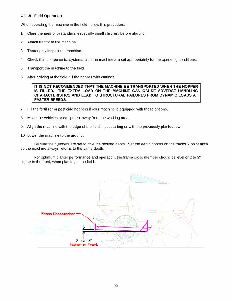
7. Fill the fertilizer or pesticide hoppers if your machine is equipped with those options. 8. Move the vehicles or equipment away from the working area. 9. Align the machine with the edge of the field if just starting or with the previously planted row. 10. Lower the machine to the ground. Be sure the cylinders are set to give the desired depth. Set the depth control on the tractor 2 point hitch so the machine always returns to the same depth. For optimum planter performance and operation, the frame cross member should be level or 2 to 3" higher in the front, when planting in the field.
33
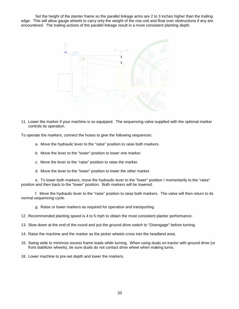
Set the height of the planter frame so the parallel linkage arms are 2 to 3 inches higher than the trailing edge. This will allow gauge wheels to carry only the weight of the row unit and float over obstructions if any are encountered. The trailing actions of the parallel linkage result in a more consistent planting depth.
11. Lower the marker if your machine is so equipped. The sequencing valve supplied with the optional marker
controls its operation. To operate the markers, connect the hoses to give the following sequences: a. Move the hydraulic lever to the “raise” position to raise both markers. b. Move the lever to the “lower” position to lower one marker. c. Move the lever to the “raise” position to raise the marker. d. Move the lever to the “lower” position to lower the other marker. e. To lower both markers, move the hydraulic lever to the “lower” position / momentarily to the “raise” position and then back to the “lower” position. Both markers will be lowered. f. Move the hydraulic lever to the “raise” position to raise both markers. The valve will then return to its normal sequencing cycle. g. Raise or lower markers as required for operation and transporting. 12. Recommended planting speed is 4 to 5 mph to obtain the most consistent planter performance. 13. Slow down at the end of the round and put the ground drive switch to “Disengage” before turning. 14. Raise the machine and the marker as the picker wheels cross into the headland area. 15. Swing wide to minimize excess frame loads while turning. When using duals on tractor with ground drive (or
front stabilizer wheels), be sure duals do not contact drive wheel when making turns. 16. Lower machine to pre-set depth and lower the markers.
34
4.12 Operating Hints If the tractor has not moved for 60 seconds, the monitor will shut off.
Start the flow control valve at the #3 setting.
Start the hydraulic speed control (rabbit and turtle) on the tractor at just under half speed. if there is not enough oil, the monitor will flash “APER”.
If the Monitor is turned on with the flush in the “auto” position and it does not work properly, check the 3-point safety switch.
Always connect the power source directly to the battery.
The frame should be level and set high enough so the parallel linkage is lower in back by 1 to 3 inches.
Keep the potato level in the bowl as low as possible.
Clear the potatoes away from the switch at the end of the day.
If seed pieces are planted too shallow, reduce speed and/or check gauge wheel depth.
18 RPM on the picker wheels has been shown to have the best consistency.
Do not use the hydraulic system to operate other equipment.
If all feeds do not run, this does not indicate an electrical problem.
SEED SIZE AND VARIETY Wide variations in the size and shape of your seed will result in poor planter performance. Although the machine can handle cut or whole seed, it has difficulty handling both at the same time because the operational settings change.
Time spent to ensure consistent seed size and type pays rich dividends in planter accuracy, consistency and faster planting.
TIRE SPACING Normally the tire spacing on the rear of the machine is set at twice the row spacing. For example: 36" rows require 72" tire spacing. However, when your machine is equipped with mono rib tires, it is recommended that the tire spacing be set to match the tire spacing of the tractor to be used during the first cultivating pass. If the spacing is not the same, the tractor will be difficult to control and keep in the center of the rows.

35
4.13 Transporting
1. Make sure you are in compliance with all local
regulations regarding transporting equipment on public roads and highways.
1. Make sure the SMV (Slow Moving Vehicle) emblem and all the lights and reflectors that are required by the local highway and transport authorities are in place, are clean, and can be seen clearly by all overtaking and oncoming traffic.
2. Do not allow anyone to ride on the Planter or
tractor during transport. 3. Do not exceed 32 km/h (20 mph). Reduce
speed on rough roads and surfaces. 4. Do not transport with tank(s) loaded.
When transporting the machine, review and follow these instructions 1. Be sure all bystanders are clear of the machine. 2. Ensure that the machine is securely attached to
the tractor and all retainer pins are installed. 3. Raise the machine and install the transport lock
before transporting. 4. Clean the SMV emblem and all lights and
reflectors before starting. 5. Be sure that all lights required by the local
highway authorities are in place, clean and functioning so they can be seen by oncoming and overtaking traffic.
6. If transporting during times of limited visibility or
dusk, install extra lights or use pilot vehicles. 7. Always use hazard flashers on the tractor when
transporting unless prohibited by law.
8. Watch through the expanded metal grill on the
hopper for overtaking traffic. Keep to the right and yield the right of way to allow faster traffic to pass. Drive on the road shoulder, if permitted by law.
9. Do not allow riders on the machine. 10. Do not transport when the machine is loaded. 11. Never exceed a safe travel speed. 12. Always shift to a lower gear when going down
hills to use the engine as a retarding force. 13. Apply the brakes carefully to prevent jackknifing. 14. Never disengage tractor drive train and coast
down hills. Always keep tractor in gear. 15. Never tow the machine faster than 20 mph (32
km/h). The ratio of the tractor weight to the planter weight plays an important role in defining acceptable travel speed.

36
4.14 STORAGE 4.14.1 PLACING IN STORAGE At the end of the planting season, the machine should be thoroughly inspected and prepared for storage. Repair or replace any worn or damaged components to prevent unnecessary down time at the beginning of the next season. Follow this procedure: 1. Thoroughly wash the machine using a pressure washer to remove all dirt, mud, debris, or residue. During the
final rinse, add a good disinfectant to the pressure washer tank to disinfect the machine.
2. If a disinfectant is not used, fungus and mildew will grow during the storage period and could contaminate
next year's crop. 3. Inspect the following components: Soil Engaging Components: a. Check for worn or damaged planting shoes. Look for signs of wear on "opening frog" of shoe. If wear is detected, rebuild or replace planting shoe. b. Check closing discs for damaged or worn bearings. Replace disc or bearings as required. c. Check opening discs for damage or worn bearings (for machines with optional fertilizer attachment). Replace disc or bearings as required. Planting Components: a. Check all pick arms for bent or broken picks. Straighten or replace as required. b. Check pick arms for damaged or broken springs. Replace as required. c. Lubricate pick arm pivot. Use WD-40, LPS -2. or equivalent to spray pivot bushing area. Work pivot arm several times to get lubricant into the bushing and then spray again. d. Rotate all picker wheels and lubricate each pick arm bushing. e. Check Cam Bearing for damage. f. Check all pick arm cams for damage, wear, or misalignment. Repair as required. g. Lubricate over-running clutch at the front of each row unit. h. Inspect and lubricate the roller chain on row unit drive. Replace damaged or worn roller chain as required. i. Repack gauge wheels on each row unit. Replace bearings with damaged seals. j. Lubricate all grease points. (see Maintenance Section).
NOTE DO NOT point high pressure directly on wire connections or encoders
If planter is equipped with fertilizer attachment, wash with a solution of 10% Vinegar / 90% Water

37
Electrical system:
a. Check the wiring harness and all wiring for damaged or worn areas. Check for cracked or worn insulation. Replace any components that have come in contact with moving parts and route to prevent damage in the future.
b. Check all seed bowl switches for proper operation. Repair or replace any damaged or malfunctioning switches or wiring harness. c. Check all hydraulic solenoids for loose or damaged wires. Repair or replace as required. 4. Make a list of all parts needed for repairs and order them immediately. Repairs can then be done when time
permits to prevent unnecessary down time at the start of next season. 5. Lubricate all grease points to remove any water residue from the washing and prevent rusting during the
storage period. Rotate all moving parts to distribute lubricant to all surfaces. 6. Coat each roller chain with a good quality chain lubricant to prevent rusting. Rotate the chain slowly by hand
to cover all surfaces. 7. Apply a light coat of grease on the shafts where the sprockets slide on the transmission driving shaft and on
the picker wheel over running clutch shaft. 8. Remove material that has become entangled in any drives. 9. Touch up all paint nicks and scratches to prevent rusting. 10. Move the machine to its storage area. 11. Select an area that is dry, level, and free of debris. 12. Place planks or blocks under the hitch pole on the pull-type model. 13. Unhook the machine from the tractor (Refer to Section 4.9). 14. Place all wiring harness and hydraulic line components in a safe place on the hitch to prevent damage and
keep clean during the storage period. 15. If the machine cannot be stored inside, cover with a waterproof tarpaulin and tie securely in place. 16. Store out of the way of human activity. 17. Do not allow children to play around stored unit.

38
4.14.2 REMOVING FROM STORAGE When removing from storage and preparing to use, follow this procedure: 1. Clear the area of bystanders, especially small children. 2. Remove the tarpaulin from the machine if it was covered. 3. Attach the tractor to the machine (See Page 24). 4. Check: a. Tire pressure. Add as required. b. Re-torque all wheel bolts. c. Re-torque all hardware. d. Routing and securing of all hydraulic lines and wiring harness. Adjust as required. 5. Rotate all components and systems by hand to see that none are seized. Loosen any seized components
with penetrating oil before starting. 6. Lubricate all grease points, roller chains, and shaft surfaces with sliding sprockets. 7. Review and follow all items on the Pre-Operation Checklist and Daily Inspection before starting.

39
5 SERVICE AND MAINTENANCE
1. Follow all the operating, maintenance, and
safety information in the manual. 2. Support the machine with blocks or safety
stands when changing tires or working beneath it.
3. Stop tractor engine, lower machine to the
ground, place all controls in neutral, set park brake, remove ignition key, and wait for all moving parts to stop before servicing, adjusting, repairing, unplugging, or filling.
4. Make sure all guards are in place and properly
secured when maintenance work is completed. 5. Never wear ill-fitting, baggy, or frayed clothing
when working around or on any of the drive system components.
6. Before applying pressure to a hydraulic system,
make sure all lines, fittings, and couplers are tight and in good condition.
7. Install safety rod and pin securely in position on
hitch cylinder frame before working under frame. Make sure safety rod is unhooked before resuming operation.
8. Relieve pressure from hydraulic circuit before
servicing or disconnecting from tractor. 9. Keep hands, feet, hair, and clothing away from
moving or rotating parts. 10. Clear the area of bystanders, especially small
children, when carrying out any maintenance and repairs or making any adjustments.
11. Wear appropriate protective gear when
contacting chemical handling components on machine.
5.1 SERVICE 5.1.1 FLUIDS AND LUBRICANTS 12. Grease
Use an SAE multi-purpose high temperature grease for all applications Also acceptable is an SAE multi-purpose lithium base grease.
13. Roller Chain Lubricant
Use WD-40, LPS-2, or equivalent to coat roller chains and bushings to prevent rusting or seizing.
14. Storing Lubricants
Your machine can operate at top efficiency only if clean lubricants are used. Use clean containers to handle all lubricants. Store them in an area protected from dust, moisture, and other contaminants.
15. When pressure washing, do not directly spray
the side (seal) of the bearing. This will damage the seal and reduce the life of the bearing.
5.1.2 GREASING Use the Maintenance Checklist provided to keep a record of all scheduled maintenance. 1. Use only a hand-held grease gun for all
greasing. Air powered greasing systems can damage the seals on bearings and lead to early bearing failure.
IMPORTANT Over-greasing can damage bearing seals. A
damaged seal will lead to early bearing failure. Replace all bearings with damaged seals
immediately. 2. Wipe grease fitting with a clean cloth before
greasing, to avoid injecting dirt and grit. 3. Replace and repair broken fittings immediately. 4. If a fitting will not take grease, remove and clean
thoroughly. Also clean lubricant passageway. Replace fitting if necessary.

40
SEALED BEARINGS Sealed bearings are used at several locations on this machine. All sealed bearings are lubricated at the factory and the seals retain the grease inside the bearing and prevent dirt and other contaminants from getting inside. The life of the sealed is virtually limitless provided it is not damaged in any way. When sealed bearings are greased, the grease is introduced next to the outer face of the seal. When a hand held grease gun is used, the grease slips in next to the seal without damaging it. An air powered greasing system will inject the grease so fast that it is no uncommon for them to damage a seal. Once the seal is damaged, the factory installed grease comes out and the bearing runs dry. Seizing will then occur in a short time. Should you notice that a seal is damaged, replace the bearing immediately to prevent problems at a later time. SEALED BEARINGS Occasional greasing of sealed bearings is required to remove moisture and contaminants from the space next to the seals. It is not recommended that sealed bearings on the machine be greased any oftener than once every season after the machine is washed and then only give them one shot. More frequent lubrication runs the risk of damaging the seals and causing bearing failure. The exception to this rule is at the beginning and end of the season. At those times, each bearing should be given only one shot of grease to remove moisture or water next to the seal that can accumulate during washing or storage. ROLLER CHAINS Check all chains daily for tension. Lubricate chains every 20 hours of operation. Tighten chains so there is approximately 1/4 to 1/2" of slack on the side of the chain opposite the tightener or so that you can slide the chain back and forth with your fingers on one of the sprockets. DO NOT over tighten. Replace all shields after servicing chains. Action Code L = Lubricate R = Repack CL = Clean D = Disinfect
Hours Maintenance Serviced By
L Gauge Wheels L Walking Beam L Over-Running Clutch L Rear Wheel Pivots
Annually L Roller Chains L Picker Wheel Drive Chain L Feeding System Drive Chain L Hydraulic Drive Roller Chain R Rear Wheel Bearings R Gauge Wheel Bearings R Picker Wheel Hubs CL & D Machine

41
5.1.3 SERVICE INTERVALS

42
SERVICE INTERVALS
Grease Daily 2 Locations per row
Grease Daily 2 Locations per Walking Beam
Repack Wheel Bearings Annually
Grease Daily 2 Locations per row
Grease Daily 8 Locations per row

43
SERVICE INTERVALS

44
5.2 MAINTENANCE 5.2.1 PICKER WHEEL DRIVE SPROCKET Each picker wheel is driven by a sprocket that mates with a roller chain on the circumference of the wheel. To check and adjust the clearance, follow this procedure: a. Checking clearance Hold the picker wheel in a stationary position and turn the drive sprocket by hand. The teeth on the sprocket should move approximately 1/16 inch (1.5 mm) to have proper clearance. Less clearance or movement can introduce vibration into the picker wheel and cause the potatoes to fall off the picks. More clearance or movement can cause uneven plant spacing. b. Adjusting clearance Loosen the bearing mount bolts on the sprocket shaft. Move bearing and shaft to the required position. Tighten the bearing bolts to their specified torque.

45
5.2.2 PICKER WHEEL TO SEED BOWL CLEARANCE The machine is designed to have a tapered clearance between the seed bowl and the picker wheel. This clearance provides a self-cleaning action, eliminates contact damage, and reduces drag on the seed piece. To set or adjust this clearance, follow this procedure: 1. Clear the area of bystanders, especially small children. 2. Raise the machine and place safety stands under the front frame. 3. Loosen the four bolts attaching the seed bowl to the row unit frame. 4. Move the bowl to the desired position. 5. The clearance at the bottom should be 1/8 to 3/16 inches (3 to 4.5 mm). 6. The clearance at the top front of the seed bowl should be 3/8 inch (9 mm). 7. Measure the clearance dimensions carefully before tightening mounting bolts. 8. Tighten mounting bolts to their specified torque levels. 9. Remove safety stands. Always support frame with safety stands before working under machine. 5.2.3 RETIMING PICKER WHEELS The picker wheels are designed to drop seed pieces into the planting shoe in an alternating sequence. To maintain proper seed spacing, the dimensions between the picking arms on the facing picking wheel must be equal. Should wear, mechanical damage or repairs change this dimension, retime the picker wheels by following this procedure: 1. Clear the area of bystanders, especially small children. 2. Raise the machine and place safety stands under the front frame. 3. Measure the distance between the pick arms so that they are centered between the two arms on the opposite wheel. 4. If not equal: a. Loosen the bearing mounting bolts on one of the picker wheel shafts. b. Slide the picker wheel back until the driving sprocket clears the wheel. c. Rotate the picker wheel slightly. d. Measure the dimension between the picking arms. e. If the dimensions are equal, move the picker wheel back into position and secure in place. f. If the dimensions are not equal, rotate the picker wheel until they are equal. g. Tighten picker wheel shaft mounting bolts to their specified torque levels. 5. Remove safety stands

46
5.2.4 ROW UNIT SHEAR BOLTS The drive of each row unit is protected by shear bolts on the driving sprocket should the picker wheel jam. To replace shear bolts, follow this procedure: 1. Clear the area of bystanders, especially small children. 2. Place all controls in neutral, stop engine, set the park brake, and remove ignition key. 3. Carefully remove remaining shear bolt using a hammer and punch if necessary. Do not enlarge holes. 4. Install new shear bolts (2 required and tighten). 5.2.5 HYDRAULICS Daily: 1. Check indicator on hydraulic filter. Replace element when indicator is in red zone. 2. Check hydraulic hoses for pinching, fraying, etc. Replace any damaged hoses. 3. Check for leaking fittings, couplers, or cylinders. Replace, repair as needed. 4. Check hydraulic control valve for any visible damage. Repair as necessary. 5.2.6 ROLLER CHAIN TENSION The machine has several roller chains that are used to transmit power. To adjust the tension of these chains, follow this procedure: 5.2.7 HYDRAULIC DRIVE CHAIN 1. The hydraulic drive chain tension is set by the idler sprocket. 2. Loosen the nut on the sprocket and slide or tap to the required position. Tighten until the long span is snug. 3. Tighten the nut on the idler sprocket.
IMPORTANT Whenever replacing hydraulic hoses and coupling or uncoupling hoses to
tractor, be sure hoses are clean to prevent contamination.

47
5.2.8 PICKER WHEEL DRIVE CHAIN 1. The picker wheels on a row unit are driven by a single chain. 2. The chain tension is set with a spring loaded idler. 3. Normal spring tension will give 1/8 inch (3mm) spacing between the coils. 4. This will keep the chain on the long span snug. 5. Check the springs on other row units as required. 5.2.9 FEEDBOX ROLLER CHAIN DRIVE 1. Each feed chain is driven by a hydraulic motor through a roller chain. 2. Loosen the nut securing the idler sprocket. 3. Slide or tap the idler into its required position. 4. The chain on the long span should be snug. Do not overtighten. 5. Tighten the idler bolt to its specified torque. 6. Repeat on the other row units as required. 5.2.10 FEED CHAIN TENSION The feed chain moves cuttings from the hopper into the seed bowls for planting. To adjust the tension, follow this procedure: 1. Loosen the chain idler bolts on both sides of the feed chain. 2. Adjust until there is approximately 1 inch (25 mm) of sag on the loose (bottom) side of the chain. 3. Tighten the chain idler bolts to their specified torque. 4. Adjust tension on the other feed chains as required.
Machine is shown with guards removed for illustrative purposes only. Do not
operate with guards removed

48
5.2.11 Operation of Feedbox Motor Control Solenoid On Harriston planters, the feedbox providing seed to the planter bowl is controlled by an electric solenoid mounted on a hydraulic motor. Oil for the hydraulic motor flows from the return side of the planter shaker drive motor. Oil flow is regulated by a manual flow control. An electric switch in the feed bowl provides 12 V.D.C. to the solenoid for control of oil flow for each individual feedbox. When the seed bowl is being filled, the electric switch is closed, which sends current to the solenoid. The solenoid closes the by-pass line in the motor manifold, which directs oil to the hydraulic motor.
In Figure 1, electric current is off, the by-pass is open, which diverts hydraulic oil away from motor; therefore the motor does not run. In Figure 2, Electric current activates magnetic solenoid. The solenoid closes the by-pass and directs oil flow to the hydraulic motor (motor runs). All feedbox motors are connected in a hydraulic series, which means hydraulic oil flows from one motor to the next. Oil flow is the same regardless of how many motors are in the circuit. As the number of motors (rows) increase, oil pressure increases proportionally. Example: one motor requires 150 P.S.I., 4 motors require 600 P.S.I. Motors that are operating require pressure. Motors that are not operating (because solenoid has opened by-pass) will not increase pressure. Pressure will continuously vary, depending upon how many motors are operating at any given time. Because all motors are connected in a series, if one stalls because of a jammed feed chain, all motors will stall because oil flow will be blocked.
Fig. 2
Oil Flow
By-pass closed
Oil flowturns motor
Spring
Valve Plunger
Fig. 1
Resistance keepsmotor from turning
Oil Flow
By-pass open
Spring
Valve Plunger
Elec. Solenoid(Power OFF)
Elec. Solenoid(Power ON)
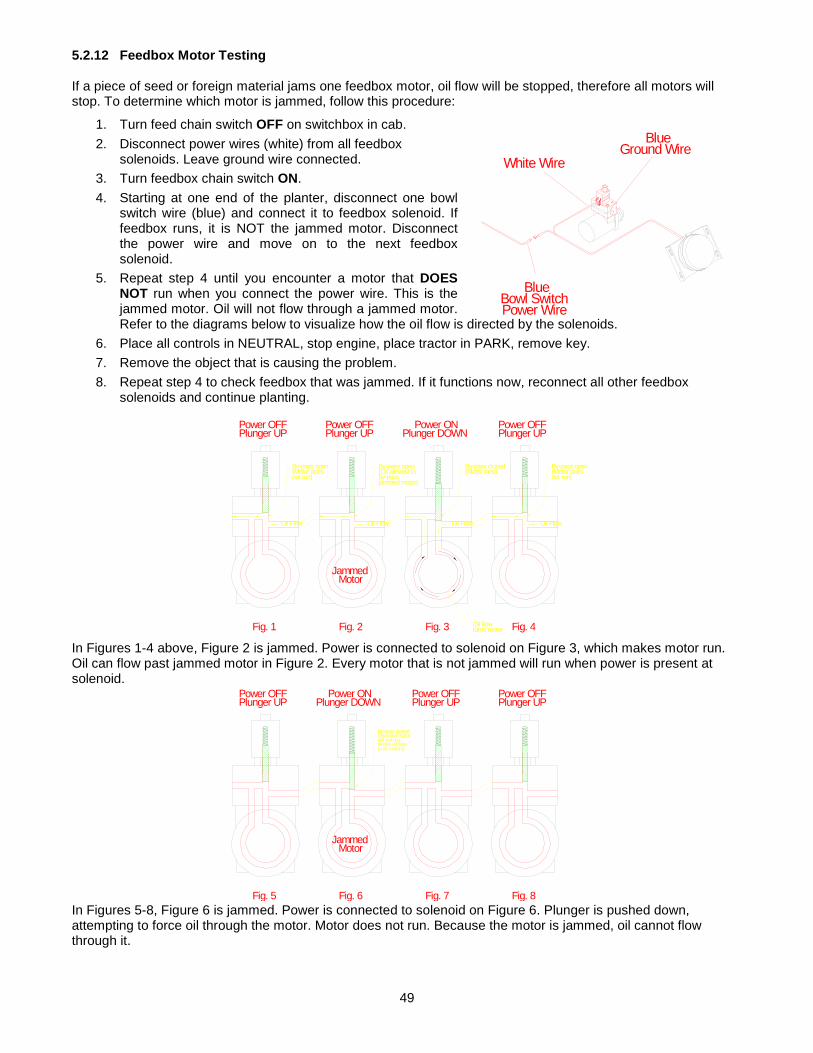
49
5.2.12 Feedbox Motor Testing If a piece of seed or foreign material jams one feedbox motor, oil flow will be stopped, therefore all motors will stop. To determine which motor is jammed, follow this procedure:
1. Turn feed chain switch OFF on switchbox in cab. 2. Disconnect power wires (white) from all feedbox
solenoids. Leave ground wire connected. 3. Turn feedbox chain switch ON. 4. Starting at one end of the planter, disconnect one bowl
switch wire (blue) and connect it to feedbox solenoid. If feedbox runs, it is NOT the jammed motor. Disconnect the power wire and move on to the next feedbox solenoid.
5. Repeat step 4 until you encounter a motor that DOES NOT run when you connect the power wire. This is the jammed motor. Oil will not flow through a jammed motor. Refer to the diagrams below to visualize how the oil flow is directed by the solenoids.
6. Place all controls in NEUTRAL, stop engine, place tractor in PARK, remove key. 7. Remove the object that is causing the problem. 8. Repeat step 4 to check feedbox that was jammed. If it functions now, reconnect all other feedbox
solenoids and continue planting. In Figures 1-4 above, Figure 2 is jammed. Power is connected to solenoid on Figure 3, which makes motor run. Oil can flow past jammed motor in Figure 2. Every motor that is not jammed will run when power is present at solenoid. In Figures 5-8, Figure 6 is jammed. Power is connected to solenoid on Figure 6. Plunger is pushed down, attempting to force oil through the motor. Motor does not run. Because the motor is jammed, oil cannot flow through it.
Power OFFPlunger UP
Power OFFPlunger UP
Power OFFPlunger UP
Power ONPlunger DOWN
JammedMotor
Fig. 5 Fig. 6 Fig. 7 Fig. 8
By-pass closed(Jammed motor will not run,blocks oil flowto all motors)
JammedMotor
Power OFFPlunger UP
Power OFFPlunger UP
Power OFFPlunger UP
Power ONPlunger DOWN
Oil Flow Oil Flow Oil Flow Oil Flow
Fig. 1 Fig. 2 Fig. 3 Fig. 4Oil flowturns motor
By-pass closed(Motor runs)
By-pass open(Motor doesnot run)
By-pass open(Oil allowed toby-passjammed motor)
By-pass open(Motor doesnot run)
BlueGround Wire
BlueBowl SwitchPower Wire
White Wire

50
5.2.13 Replacing Bowl Switch Pictured below is the wiring diagram for bowl switch. Always replace diode when replacing bowl switch. DIODE MUST BE INSTALLED AS SHOWN. PAY ATTENTION TO LOCATION OF GREY STRIPE.
5.2.14 Rebuilding Shoes If you wish to build up worn planter shoes, the following figures show the approximate dimensions of new shoes.
Com
OnNC
Black
Grey Stripe
White
Diode

51
5.2.15 Walking Beam Tracking/Adjustment The walking beams must be adjusted to make the planter track properly (pull straight) behind the tractor. The walking beams must be parallel to the tool bar under the tank. Follow this procedure to adjust walking beams:
a. Seed / fertilizer tanks should be empty prior to adjusting walking beams (A). b. Position planter on smooth firm surface. c. The goal is for the measurement at (B) to be equal at both ends of each walking beam. d. Loosen (DO NOT REMOVE) 4 bolts (C) on walking beam frame. e. Using a method of tightening one adjusting bolt (D) and loosening the other one, adjust until
measurement is the same at both ends of walking beam. f. Use a square as shown (E) or a tape measure if a square is not available. After adjusting, tighten
bolts to recommended torque, move planter forward 50 – 100’ and recheck measurements.
A
B B
C
C
CC
D
D
E
Gro
und
B

52
PICK WHEEL SPEED BASED ON GROUND SPEED & SEED SPACING18 RPMS (TARGET RPM)
seed spacingspeed 6 7 8 9 10 11 12 13 14 15 16 17
1.00 7.3 6.3 5.5 4.9 4.4 4.0 3.7 3.4 3.1 2.9 2.8 2.61.50 11.0 9.4 8.3 7.3 6.6 6.0 5.5 5.1 4.7 4.4 4.1 3.92.00 14.7 12.6 11.0 9.8 8.8 8.0 7.3 6.8 6.3 5.9 5.5 5.22.50 18.3 15.7 13.8 12.2 11.0 10.0 9.2 8.5 7.9 7.3 6.9 6.52.75 20.2 17.3 15.1 13.4 12.1 11.0 10.1 9.3 8.6 8.1 7.6 7.12.81 20.6 17.7 15.5 13.7 12.4 11.2 10.3 9.5 8.8 8.2 7.7 7.33.00 22.0 18.9 16.5 14.7 13.2 12.0 11.0 10.2 9.4 8.8 8.3 7.83.25 23.8 20.4 17.9 15.9 14.3 13.0 11.9 11.0 10.2 9.5 8.9 8.43.50 25.7 22.0 19.3 17.1 15.4 14.0 12.8 11.8 11.0 10.3 9.6 9.13.75 27.5 23.6 20.6 18.3 16.5 15.0 13.8 12.7 11.8 11.0 10.3 9.74.00 29.3 25.1 22.0 19.6 17.6 16.0 14.7 13.5 12.6 11.7 11.0 10.44.10 30.1 25.8 22.6 20.0 18.0 16.4 15.0 13.9 12.9 12.0 11.3 10.64.25 31.2 26.7 23.4 20.8 18.7 17.0 15.6 14.4 13.4 12.5 11.7 11.04.50 33.0 28.3 24.8 22.0 19.8 18.0 16.5 15.2 14.1 13.2 12.4 11.64.75 34.8 29.9 26.1 23.2 20.9 19.0 17.4 16.1 14.9 13.9 13.1 12.35.00 36.7 31.4 27.5 24.4 22.0 20.0 18.3 16.9 15.7 14.7 13.8 12.95.25 38.5 33.0 28.9 25.7 23.1 21.0 19.3 17.8 16.5 15.4 14.4 13.65.50 40.3 34.6 30.3 26.9 24.2 22.0 20.2 18.6 17.3 16.1 15.1 14.25.75 42.2 36.1 31.6 28.1 25.3 23.0 21.1 19.5 18.1 16.9 15.8 14.96.00 44.0 37.7 33.0 29.3 26.4 24.0 22.0 20.3 18.9 17.6 16.5 15.56.25 45.8 39.3 34.4 30.6 27.5 25.0 22.9 21.2 19.6 18.3 17.2 16.26.50 47.7 40.9 35.8 31.8 28.6 26.0 23.8 22.0 20.4 19.1 17.9 16.86.75 49.5 42.4 37.1 33.0 29.7 27.0 24.8 22.8 21.2 19.8 18.6 17.57.00 51.3 44.0 38.5 34.2 30.8 28.0 25.7 23.7 22.0 20.5 19.3 18.17.50 55.0 47.1 41.3 36.7 33.0 30.0 27.5 25.4 23.6 22.0 20.6 19.48.00 58.7 50.3 44.0 39.1 35.2 32.0 29.3 27.1 25.1 23.5 22.0 20.7
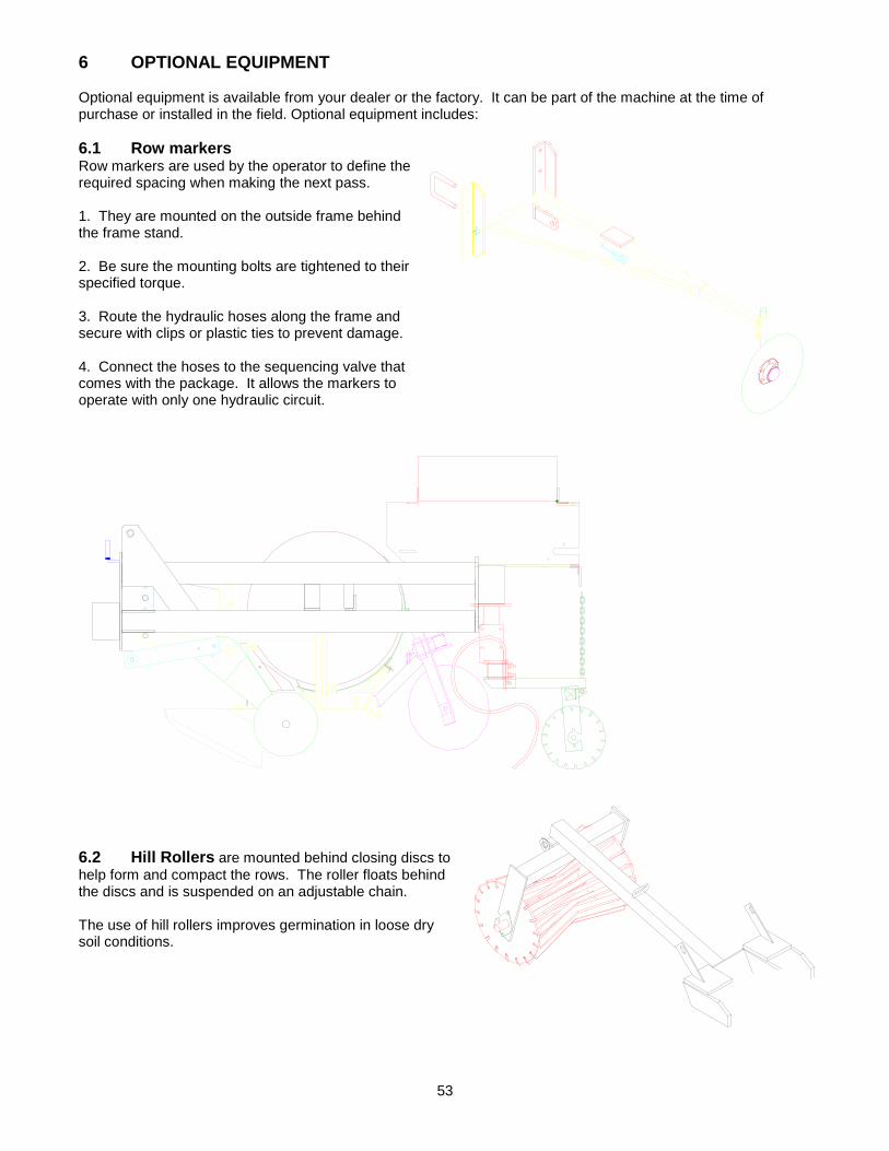
53
6 OPTIONAL EQUIPMENT Optional equipment is available from your dealer or the factory. It can be part of the machine at the time of purchase or installed in the field. Optional equipment includes: 6.1 Row markers Row markers are used by the operator to define the required spacing when making the next pass. 1. They are mounted on the outside frame behind the frame stand. 2. Be sure the mounting bolts are tightened to their specified torque. 3. Route the hydraulic hoses along the frame and secure with clips or plastic ties to prevent damage. 4. Connect the hoses to the sequencing valve that comes with the package. It allows the markers to operate with only one hydraulic circuit.
6.2 Hill Rollers are mounted behind closing discs to help form and compact the rows. The roller floats behind the discs and is suspended on an adjustable chain. The use of hill rollers improves germination in loose dry soil conditions.

54
6.3 Deer Tong Ripper Shank This ripper shank is used to break up the tractor tire track. It mounts on the front of the planter frame directly behind the tractor tire.
6.4 Trash Shank In soil with heavy trash conditions, a toolbar mounted 1” flex coil shank can be used in front of each row unit. They are attached with an adjustable bracket.
6.5 Rear Ripper This S-Tine is used to break up the tire track or break up the ground between all the rows.

55
6.6 Pesticide Applicator The package consists of a 90 lb (40 kg) box for one or two rows (must be specified at the time of purchase), mounting frame, and drive system. Mounting may differ depending on planter options installed; platforms, dry fertilizer, etc. 1. Install the mounting frame to the planter frame so the boxes are positioned above the parallel linkage arms. 2. Tighten mounting bolts to their specified torque. 3. Install the drive system on the left side of the machine. A sprocket is installed on the shaft and a roller chain transmits the power to the common metering shaft. (see applicator instructions). 4. Install the applicator boxes on the frame. 5. Install the metering shaft between each box. 6. Install the material tubes to the bottom of the boxes. 7. Tighten all mounts and fasteners. 8. Install all shields. 6.7 HARRISTON MECHANICAL DRIVE FERTILIZER The mechanical drive system transmits power from the row unit drive shaft to the 21 speed gearbox and then to the fertilizer feedbox. Application rates are adjusted by the gearbox in combinations with an adjustable gate. Rates can be adjusted from less than 150 lbs... to over 200 lbs per acre. NEVER TRANSPORT PLANTER WITH FERTILIZER TANK FULL. TO CHANGE RATIO OF GEARBOX: Release the center gear by turning center handle 180°. Never attempt to change ratios with the center gear in locked position. Engage center gear by turning operating handle 180° to operating position. If handle does not engage easily it may be necessary to turn either input or output shaft slightly to realign gears.
Never force any of the selector handles or the operating handle. If center operating handle cannot be easily turned or if selector handles are not in desired notches , remove cover from gearbox and check the gear alignment. With the selector handles in A-5 position as shown at right, selector gears must be in outer most positions. If gears are not in position shown, release center gear by turning release handle 180°. Loosen set screws located on operating handles and place handles in A-5 position. Move sliding gears to outer most positions on center gear. Lock operating handle, and tighten set screws. If the sliding gears are not in the correct position gear ratios will not correspond with chart. Gearbox should have approximately 2-1/2 gallons of 80-90 oil.
48 Teeth
42 Teeth36 Teeth
30 Teeth
24 Teeth24 Teeth

56
The fertilizer rates that appear in the following tables should only be used as a guideline. The rates shown were determined mathematically. Various factors such as fertilizer blend, granular size, and humidity can drastically affect actual delivery rates. Rate variation of 10% from chart is not uncommon. Always calibrate your machine to determine actual rate applied. To determine actual fertilizer output of your machine select gearbox and gate opening, tie a catch bag or pail to the output from each row. Measure out and drive the distance shown for your row spacing. Weigh the collected fertilizer and multiply by 100. Weigh the amount collected from each row separately. Distance to travel row spacing 32" 163 ft
to cover 100th of an acre/row
34 154 36 145 38 138 40 131 Check calibration periodically and adjust as necessary. Conditions such as humidity and blend may change application rate. Check gearbox oil weekly. Repack fertilizer disc bearings annually. Before storage or if unit will not be used for an extended period thoroughly wash unit with a 90% water 10% vinegar solution. After unit is dry spray with light oil or diesel fuel. The fertilizer charts are provided for 12" seed spacings. To set the application rate for other seed spacing, use the conversion multipliers. To use the chart, first determine the weight of the fertilizer you are using in lbs per cubic feet, the rate per acre you wish to apply, seed spacing, and the row spacing of your planter. Example: 900 lb rate 34" rows 55 lb fertilizer 10" seed spacing On the 34" row spacing chart find the conversion multiplier (middle of page) for 10" seed spacing (.833). 900 lbs X .833 = 749.7 (750) On the chart in the 55 column find the closest number to 750 which is 753. On the left side of the chart will be the gearbox setting - C-2 with a 1" Gate opening. Four charts are included in this book 34",36",38",40" at 1/2" and 1" gate openings. Other spacings or gate openings are available by calling Harriston Industries..
For 36" rows travel 145 ft the average fertilizer collected per row 63 lbs. 63 x 100 = 630 lbs per acre.

57
FERTILIZER RATE CHARTS 0.5 " Gate opening 34 " Row Spacing 12 " Seed Spacing
above chain
Gearbox Fertilizer (lbs. per cubic foot)Gear Ratio Setting 45 50 55 60 65 70 75 80 85
0.500 E-5 163 181 200 218 236 254 272 290 3080.570 E-4 186 207 228 248 269 290 310 331 3520.625 D-5 204 227 249 272 295 318 340 363 3860.667 E-3 218 242 266 290 315 339 363 387 4110.710 D-4 232 258 283 309 335 361 386 412 4380.750 C-5 245 272 299 327 354 381 408 435 4630.800 E-2 261 290 319 348 377 406 435 464 4940.833 D-3 272 302 333 363 393 423 453 484 5140.860 C-4 281 312 343 374 406 437 468 499 5310.875 B-5 286 318 349 381 413 445 476 508 5401.000 A-5 327 363 399 435 472 508 544 581 6171.140 A-4 372 414 455 496 538 579 621 662 7031.167 B-3 381 423 466 508 551 593 635 678 7201.200 C-2 392 435 479 523 566 610 653 697 7401.250 D-1 408 454 499 544 590 635 680 726 7711.333 A-3 435 484 532 580 629 677 726 774 8221.400 B-2 457 508 559 610 660 711 762 813 8641.500 C-1 490 544 599 653 708 762 816 871 9251.600 A-2 523 581 639 697 755 813 871 929 9871.750 B-1 572 635 699 762 826 889 953 1016 10802.000 A-1 653 726 798 871 943 1016 1089 1161 1234
6" = .5 10" = .833 14" = 1.167 18" = 1.507" = .583 11" = .916 15" = 1.25 19" = 1.5838" = .667 12" = 1.00 16" = 1.333 20" = 1.6679" = .750 13" = 1.08 17" = 1.416
1 " Gate opening (inches) 34 " Row Spacing 12 " Seed Spacingabove chain
Gearbox Fertilizer (lbs. per cubic foot)Gear Ratio Setting 45 50 55 60 65 70 75 80 85
0.500 E-5 257 285 314 342 371 399 428 456 4850.570 E-4 293 325 358 390 423 455 488 520 5530.625 D-5 321 356 392 428 463 499 535 570 6060.667 E-3 342 380 418 456 494 532 571 609 6470.710 D-4 364 405 445 486 526 567 607 648 6880.750 C-5 385 428 470 513 556 599 642 684 7270.800 E-2 411 456 502 547 593 639 684 730 7760.833 D-3 428 475 523 570 618 665 713 760 8080.860 C-4 441 490 539 588 638 687 736 785 8340.875 B-5 449 499 549 599 649 699 748 798 8481.000 A-5 513 570 627 684 741 798 855 912 9691.140 A-4 585 650 715 780 845 910 975 1040 11051.167 B-3 599 665 732 799 865 932 998 1065 11311.200 C-2 616 684 753 821 890 958 1026 1095 11631.250 D-1 642 713 784 855 927 998 1069 1140 12121.333 A-3 684 760 836 912 988 1064 1140 1216 12921.400 B-2 719 798 878 958 1038 1118 1198 1277 13571.500 C-1 770 855 941 1026 1112 1198 1283 1369 14541.600 A-2 821 912 1004 1095 1186 1277 1369 1460 1551
Example: to convert from 12" seed spacing to 10" at 900 lbs/ cubic feet at 55 lb fert.
900 x .833 = 750753 at a 1" gate = C-2
Conversion Multipliers

58
FERTILIZER RATE CHARTS 0.5 " Gate opening 36 " Row Spacing 12 " Seed Spacing
above chain
Gearbox Fertilizer (lbs. per cubic foot)Gear Ratio Setting 45 50 55 60 65 70 75 80 85
0.500 E-5 154 171 188 206 223 240 257 274 2910.570 E-4 176 195 215 234 254 273 293 313 3320.625 D-5 193 214 236 257 278 300 321 343 3640.667 E-3 206 229 251 274 297 320 343 366 3890.710 D-4 219 243 268 292 316 341 365 389 4140.750 C-5 231 257 283 308 334 360 386 411 4370.800 E-2 247 274 302 329 356 384 411 439 4660.833 D-3 257 285 314 343 371 400 428 457 4850.860 C-4 265 295 324 354 383 413 442 472 5010.875 B-5 270 300 330 360 390 420 450 480 5101.000 A-5 308 343 377 411 446 480 514 548 5831.140 A-4 352 391 430 469 508 547 586 625 6641.167 B-3 360 400 440 480 520 560 600 640 6801.200 C-2 370 411 452 494 535 576 617 658 6991.250 D-1 386 428 471 514 557 600 643 685 7281.333 A-3 411 457 503 548 594 640 685 731 7771.400 B-2 432 480 528 576 624 672 720 768 8161.500 C-1 463 514 565 617 668 720 771 823 8741.600 A-2 494 548 603 658 713 768 823 877 9321.750 B-1 540 600 660 720 780 840 900 960 10202.000 A-1 617 685 754 823 891 960 1028 1097 1165
6" = .5 10" = .833 14" = 1.167 18" = 1.507" = .583 11" = .916 15" = 1.25 19" = 1.5838" = .667 12" = 1.00 16" = 1.333 20" = 1.6679" = .750 13" = 1.08 17" = 1.416
1 " Gate opening (inches) 36 " Row Spacing 12 " Seed Spacingabove chain
Gearbox Fertilizer (lbs. per cubic foot)Gear Ratio Setting 45 50 55 60 65 70 75 80 85
0.500 E-5 242 269 296 323 350 377 404 431 4580.570 E-4 276 307 338 368 399 430 460 491 5220.625 D-5 303 337 370 404 438 471 505 539 5720.667 E-3 323 359 395 431 467 503 539 575 6110.710 D-4 344 382 421 459 497 535 574 612 6500.750 C-5 364 404 444 485 525 565 606 646 6870.800 E-2 388 431 474 517 560 603 646 689 7320.833 D-3 404 449 493 538 583 628 673 718 7630.860 C-4 417 463 509 556 602 648 695 741 7870.875 B-5 424 471 518 565 613 660 707 754 8011.000 A-5 485 539 592 646 700 754 808 862 9161.140 A-4 553 614 675 737 798 860 921 982 10441.167 B-3 566 629 691 754 817 880 943 1006 10681.200 C-2 582 646 711 776 840 905 969 1034 10991.250 D-1 606 673 741 808 875 942 1010 1077 11441.333 A-3 646 718 790 861 933 1005 1077 1149 12201.400 B-2 679 754 829 905 980 1056 1131 1206 12821.500 C-1 727 808 889 969 1050 1131 1212 1293 13731.600 A-2 776 862 948 1034 1120 1206 1293 1379 1465
Example: to convert from 12" seed spacing to 10" at 900 lbs/ cubic feet at 55 lb fert.
900 x .833 = 750741 at a 1" gate = D-1
Conversion Multipliers

59
FERTILIZER RATE CHARTS 0.5 " Gate opening 38 " Row Spacing 12 " Seed Spacing
above chain
Gearbox Fertilizer (lbs. per cubic foot)Gear Ratio Setting 45 50 55 60 65 70 75 80 85
0.500 E-5 146 162 179 195 211 227 244 260 2760.570 E-4 167 185 204 222 241 259 278 296 3150.625 D-5 183 203 223 244 264 284 304 325 3450.667 E-3 195 217 238 260 282 303 325 347 3680.710 D-4 207 231 254 277 300 323 346 369 3920.750 C-5 219 244 268 292 317 341 365 390 4140.800 E-2 234 260 286 312 338 364 390 416 4420.833 D-3 243 270 298 325 352 379 406 433 4600.860 C-4 251 279 307 335 363 391 419 447 4750.875 B-5 256 284 313 341 369 398 426 455 4831.000 A-5 292 325 357 390 422 455 487 519 5521.140 A-4 333 370 407 444 481 518 555 592 6291.167 B-3 341 379 417 455 493 530 568 606 6441.200 C-2 351 390 429 468 507 545 584 623 6621.250 D-1 365 406 446 487 528 568 609 649 6901.333 A-3 390 433 476 519 563 606 649 692 7361.400 B-2 409 455 500 545 591 636 682 727 7731.500 C-1 438 487 536 584 633 682 731 779 8281.600 A-2 468 519 571 623 675 727 779 831 8831.750 B-1 511 568 625 682 739 795 852 909 9662.000 A-1 584 649 714 779 844 909 974 1039 1104
6" = .5 10" = .833 14" = 1.167 18" = 1.507" = .583 11" = .916 15" = 1.25 19" = 1.5838" = .667 12" = 1.00 16" = 1.333 20" = 1.6679" = .750 13" = 1.08 17" = 1.416
1 " Gate opening (inches) 38 " Row Spacing 12 " Seed Spacingabove chain
Gearbox Fertilizer (lbs. per cubic foot)Gear Ratio Setting 45 50 55 60 65 70 75 80 85
0.500 E-5 230 255 281 306 332 357 383 408 4340.570 E-4 262 291 320 349 378 407 436 465 4940.625 D-5 287 319 351 383 415 446 478 510 5420.667 E-3 306 340 374 408 442 476 510 545 5790.710 D-4 326 362 398 435 471 507 543 580 6160.750 C-5 344 383 421 459 497 536 574 612 6510.800 E-2 367 408 449 490 531 571 612 653 6940.833 D-3 383 425 468 510 553 595 638 680 7230.860 C-4 395 439 483 527 570 614 658 702 7460.875 B-5 402 446 491 536 580 625 670 714 7591.000 A-5 459 510 561 612 663 714 765 816 8671.140 A-4 523 582 640 698 756 814 872 931 9891.167 B-3 536 595 655 715 774 834 893 953 10121.200 C-2 551 612 673 735 796 857 918 980 10411.250 D-1 574 638 702 765 829 893 957 1020 10841.333 A-3 612 680 748 816 884 952 1020 1088 11561.400 B-2 643 714 786 857 929 1000 1071 1143 12141.500 C-1 689 765 842 918 995 1071 1148 1225 13011.600 A-2 735 816 898 980 1061 1143 1225 1306 1388
Example: to convert from 12" seed spacing to 10" at 900 lbs/ cubic feet at 55 lb fert.
900 x .833 = 750748 at a 1" gate = A-3
Conversion Multipliers

60
FERTILIZER RATE CHARTS 0.5 " Gate opening 40 " Row Spacing 12 " Seed Spacing
above chain
Gearbox Fertilizer (lbs. per cubic foot)Gear Ratio Setting 45 50 55 60 65 70 75 80 85
0.500 E-5 139 154 170 185 200 216 231 247 2620.570 E-4 158 176 193 211 229 246 264 281 2990.625 D-5 174 193 212 231 251 270 289 308 3280.667 E-3 185 206 226 247 267 288 309 329 3500.710 D-4 197 219 241 263 285 307 328 350 3720.750 C-5 208 231 254 278 301 324 347 370 3930.800 E-2 222 247 271 296 321 345 370 395 4190.833 D-3 231 257 283 308 334 360 385 411 4370.860 C-4 239 265 292 318 345 371 398 424 4510.875 B-5 243 270 297 324 351 378 405 432 4591.000 A-5 278 308 339 370 401 432 463 494 5241.140 A-4 316 352 387 422 457 492 527 563 5981.167 B-3 324 360 396 432 468 504 540 576 6121.200 C-2 333 370 407 444 481 518 555 592 6291.250 D-1 347 386 424 463 501 540 578 617 6551.333 A-3 370 411 452 493 535 576 617 658 6991.400 B-2 389 432 475 518 561 605 648 691 7341.500 C-1 416 463 509 555 601 648 694 740 7871.600 A-2 444 494 543 592 642 691 740 790 8391.750 B-1 486 540 594 648 702 756 810 864 9182.000 A-1 555 617 679 740 802 864 925 987 1049
6" = .5 10" = .833 14" = 1.167 18" = 1.507" = .583 11" = .916 15" = 1.25 19" = 1.5838" = .667 12" = 1.00 16" = 1.333 20" = 1.6679" = .750 13" = 1.08 17" = 1.416
1 " Gate opening (inches) 40 " Row Spacing 12 " Seed Spacingabove chain
Gearbox Fertilizer (lbs. per cubic foot)Gear Ratio Setting 45 50 55 60 65 70 75 80 85
0.500 E-5 218 242 267 291 315 339 364 388 4120.570 E-4 249 276 304 332 359 387 414 442 4700.625 D-5 273 303 333 364 394 424 454 485 5150.667 E-3 291 323 356 388 420 453 485 517 5500.710 D-4 310 344 379 413 447 482 516 551 5850.750 C-5 327 364 400 436 473 509 545 582 6180.800 E-2 349 388 427 465 504 543 582 620 6590.833 D-3 363 404 444 485 525 565 606 646 6860.860 C-4 375 417 459 500 542 584 625 667 7090.875 B-5 382 424 467 509 551 594 636 679 7211.000 A-5 436 485 533 582 630 679 727 776 8241.140 A-4 497 553 608 663 718 774 829 884 9391.167 B-3 509 566 622 679 735 792 848 905 9621.200 C-2 523 582 640 698 756 814 872 931 9891.250 D-1 545 606 666 727 788 848 909 969 10301.333 A-3 582 646 711 775 840 905 969 1034 10981.400 B-2 611 679 746 814 882 950 1018 1086 11541.500 C-1 654 727 800 872 945 1018 1091 1163 12361.600 A-2 698 776 853 931 1008 1086 1163 1241 1318
Example: to convert from 12" seed spacing to 10" at 900 lbs/ cubic feet at 55 lb fert.
900 x .833 = 750746 at a 1" gate = B-2
Conversion Multipliers

61
Ground Drive Seed Spacing Charts
1 095048 #60 Roller Chain 2 095048 #60 Roller Chain U.S. 095049 #60 Connector Link NOTE: Sprocket “D” is on Wheel
STANDARD
A
B
C
D
1
2

62
Ground Drive Seed Spacing Charts

63
7 TROUBLE SHOOTING If you encounter a problem that is difficult to solve, even after having read through this trouble shooting section, please call your local dealer or the factory. Before you call, please have this Operator's Manual and the serial number from your planter ready. 7.1 MACHINE TROUBLE SHOOTING
PROBLEM CAUSE SOLUTION All hydraulic feeds do not run
Hydraulic lever on tractor in neutral position.
Place hydraulic lever in work position.
NOTE: this will not indicate an electrical problem
Hydraulic hose not connected. Plug hose into tractor
NOTE: Hydraulic feed is equipped with a one way check valve to prevent system from running in reverse
Operator is attempting to operate hydraulic drive in reverse.
Run hydraulic drive in proper direction.
One way check valve malfunctioning
Replace check valve. (Valve is located behind hydraulic coupler on inlet line).
Malfunctioning hydraulic coupler. Check coupler for foreign object, replace if necessary
Malfunctioning tractor hydraulic coupler
Plug couplers into another valve if available, check with tractor dealer.
Hydraulic flow control set too low or shut off.
Increase hydraulic flow
One hydraulic drive does not run, all others O.K.
Potato seed piece has wedged electric control switch in closed position.
Remove wedged potato seed piece. Note: If this is a common problem, readjust electric switch UP on mounting plate.
Malfunctioning control switch. If unit doesn't run while in “ON” position, replace switch
Object wedged in feed chain Remove wedged object Malfunctioning hydraulic motor Replace hydraulic motor
Broken drive chain Repair or replace chain Malfunctioning solenoid valve on
hydraulic motor Replace solenoid
One hydraulic drive runs continuously, all others normal
(No power at switch). Broken or unplugged wire between junction box and row unit switch
Plug wire back in. Repair broken wire. Correct problem that broke wire.
(Power at switch). Bad switch Replace switch (see page 50) (Power at switch, no power at
solenoid). Broken wire between junction box and solenoid.
Repair broken wire, correct problem that broke wire.
Seed piece wedged between switch plate and seed bowl.
Remove seed pieces. Adjust switch plate UP if problem continues.

64
PROBLEM CAUSE SOLUTION All hydraulic drives will not run Main wire harness broken,
unplugged Repair broken wire. Plug wire back in.
NOTE: When checking for electrical problems, it is suggested that a continuity tester and test light be used.
Fuse blown. Replace fuse, check for reason fuse blew.
Defective ON-OFF switch Replace switch in switchbox
Planter has too many misses, empty picks
Bent or broken picks. Replace picks Find reason for damaged picks; rocks in seed, etc.
Picks in wrong position for seed size.
Change pick position (see page 27)
Planting speed too slow. Seed cutter improperly adjusted.
Increase planting speed. Readjust seed cutter
Seed drops OFF picks before reaching release point. (Early drop).
Picks in wrong position. Change pick position (see page 27)
Planting speed too slow. Increase planting speed Pick wheel to drive sprocket
clearance too tight Readjust drive sprocket clearance (see page 44)
Planter picking too many doubles Picks in wrong position. Change pick position (see page 27)
Seed cut too small. Readjust seed cutter. Too much seed in seed bowl Reduce amount of seed in seed
bowl. (see page 30) Planter wheel carrying seed around that is not on picks.
Planting speed too fast. Slow down planting speed
Too much seed in seed bowls Reduce amount of seed in seed bowl. (See page 30)
Feed chain constantly over-fills seed bowl.
Feed chain running too fast Slow down feed chain (see page 29)
One or more pick arms not opening
Missing cam roller Replace cam roller
Broken arm, misadjusted cam Replace, readjust cam One or more pick arms not closing
Broken pick arm spring Replace spring
Damaged pick arm Replace pick arm Foreign object wedged behind
pick arm. Clean out pick arm
Soil plugging between gauge wheels and planter shoe.
Too much debris in field Rework field if possible.
Uneven planting depth Front of planter frame too low. Lift planter hitch slightly Field condition too soft. Rework field to improve seedbed. Plant spacing not the same as indicated on seed chart (Ground Drive)
Excess wheel slippage. Tighten springs on drive wheel.
Rework field to improve seedbed.
Change to different speed ratio to compensate for wheel slippage.
Improper drive wheel tire pressure
Inflate tire to proper pressure.

65
PROBLEM CAUSE SOLUTION
One row unit not planting all others normal
Broken shear bolts Replace shear bolts (see page 46)
Poor seed placement. Number of seed pieces is correct but placement is unacceptable.
Excess speed. Slow down.
Worn planter shoe Rebuild or replace shoe. Closing discs are set too deep
(distributing seed furrow). Set closing discs to a shallower position.
Seed piece depth uneven, seed is at different depths in hill
Closing discs set too close together or at too much of an angle (filling in seed furrow before seed drops).
Readjust closing discs.
Front of planter frame is too low. Raise front of planter slightly.

66
7.2 CONTROL SYSTEM CHECK PROCEDURE If the Dickey John Control System does not work properly, follow this checklist to attempt to determine the source of problem. 1. Shut the tractor hydraulics off.
2. Disconnect the Status Switch if planter is equipped with one.
3. Turn Off/Auto/Flush Switch to “Off”.
4. Hold Off/Auto/Flush Switch in the “FLUSH” position for approx. 5 seconds
5. If display shows APER , and Alarm sounds, release Off/Auto/Flush Switch. The console, Off/Auto/Flush Switch module, wiring harness to valve/driver module, and hydraulic valve are all working properly if APER disappears from the display & the alarm stops when switch is released.
6. Turn the tractor hydraulics on and repeat test. If the planter does not run, the problem is likely to do with the hydraulic system and not the electrical system.
7. If APER does not appear in display when Off/Auto/Flush Switch is held in the “FLUSH” position with the hydraulics off, check all wiring connections and valve driver module. The most common problem is driver module failure.
HYDRAULIC SYSTEM CHECK PROCEDURE.
All planters may be operated either in an open or closed center mode. On 1998 and newer planters a selector valve has been provided to operate in either an open or closed mode. When the selector valve is in vertical position hydraulic system is in open center. Turning selector valve handle to horizontal position puts system in closed center. The selector valve is located directly below planter control valve. Check with your tractor dealer as to which system your tractor should be operated in. Some tractor brands vary systems from model to model. As a general rule all JD systems are operated as a closed system. It is recommended that Case IH and Ford New Holland be operated as an open system. On tractors with priority valves, it has been observed that tractor hydraulic system runs more efficiently if planter is not run on priority valve. If it is suspected that the hydraulic drive motor may be malfunctioning: Remove drive chain Remove both hydraulic hoses Turn motor slowly with a wrench - stay clear of hydraulic oil coming from motor. Observe the feel of the motor through 3 or 4 complete rotations. You will feel some resistance as motor turns past gear rotors, but motor should have the same feel through a complete rotation. If motor binds or feels very rough through any part of rotation, replace hydraulic motor.
More Trouble Shooting for control system on next page.

67
CONTROL SYSTEM TROUBLE SHOOTING
PROBLEM CAUSE SOLUTION Console will not turn on
Console not connected to 12V. Console must be connected to 12V. Console must be connected directly to battery. Do not connect to convenience outlet in tractor
Broken wire. Check all connections. Repair broken wire
Poor or corroded connection Make sure all connections are clean & free from corrosion, especially ground wire.
Blown Fuse Find cause of blown fuse. Replace fuse.
Console reads “OFF” Off/Auto/Flush Switch module in auto position.
Return to “OFF” Position
Battery Voltage below 9 Volts. Console must be connected directly to battery. Do not connect to convenience outlet in tractor
Alarm sounds continuously Battery Voltage low (below 10.5V).
Check voltage. Console must be connected to 12V. Console must be connected directly to battery. Do not connect to convenience outlet in tractor
“SETUP” flashing on console Console is in SETUP Mode To enter OPERATE Mode, press and hold the OPER/SETUP touch switch until “SETUP” message turns off (approx. 3 Seconds)
Alarm sounds (beeps) APER Flashes
Normal alarm condition for application error (valve wide open)
OFF/AUTO/FLUSH switch module is in AUTO or FLUSH, Console displays APER
Control valve is wide open Check shaft speed sensor
Console doesn’t read shaft speed monitor fast enough for the speed you are driving
Check hydraulic oil flow. Drive slower
Inadequate oil flow from tractor Increase oil flow
Planter does not run when tractor is moving/planter runs in FLUSH Mode
Faulty wires to Radar Scope Check/clean all wire connections
Incorrect Radar mounting angle Radar must be mounted at 35° (see page 23)
If the radar wiring harness is equipped with a “Y” cable, yellow tag on cable connects to planter harness.
Defective Radar Replace radar unit. NOTE: NEVER ATTEMPT ANY REPAIRS ON THE RADAR UNIT

68
PROBLEM CAUSE SOLUTION
System will not run in AUTO Mode
Planter must be moving for the system to run in “AUTO”.
Will it run in “FLUSH” Mode?
a. System runs in FLUSH Mode, Alarm beeps and display shows APER
Control valve is wide open whenever APER message is displayed.
Check hyd. fluid level
Check hyd. couplers on tractor
b. Display shows .0 and bar graph area is blank
No ground speed or extremely slow ground speed for programmed application rate.
Speed sensor setup position I (see page 22)
Defective Speed Sensor Replace speed sensor.
System will not run in FLUSH Mode
Flush Flow Rate set incorrectly Set Flush Flow Rate in console, position F. (See page 22)
a. Alarm beeps and display shows APER
Control valve is wide open whenever APER message is displayed. No oil flow from tractor or oil flow is too low.
Increase oil flow from tractor
b. Display shows .0 and bar graph area is blank
Flush Flow Rate is set to 0000. Set Flush Flow Rate in console, position F. (see page 22)
Defective OFF/AUTO/FLUSH switch module.
Replace Switch Module
APER displayed flashing. Alarm should also be beeping
Control valve is wide open. The console is looking for a higher shaft speed than is available.
What happens in “FLUSH” Mode?
System runs at full speed. APER displayed and alarm is beeping
No Signal from shaft speed sensor.
Check shaft speed sensor coupler for loose mounting screws
Broken/corroded sensor wire Check/clean all sensor wire connections
Defective sensor Replace sensor
Planter does not completely stop when tractor stops
Setscrew on control valve has worked loose
Zero out control valve and retighten setscrew.
Planter does not hold a constant speed or seed spacing is not uniform. Planter stops when there is no forward movement and planter works in FLUSH Mode
Radar Scope mounted incorrectly Radar must be mounted at 35° (see page 23)
Faulty wires to Radar Scope Check/clean all wire connections
Obstruction(s) in radar line of sight
Remove obstruction(s)
Low voltage Console must be connected to 12V. Console must be connected directly to battery. Do not connect to convenience outlet in tractor (Very important on JD tractors equipped with radar)
Defective Radar Replace Radar

69
PROBLEM CAUSE SOLUTION
Planter does not hold a constant speed or surges when planting and also in FLUSH Mode
Loose mounting screws on shaft speed sensor
Tighten screws on shaft speed sensor
Shaft speed sensor wires broken or corroded
Check/clean all sensor wire connections
Incorrect System Response number in console program
System Response number must be .750 or less. (Make sure decimal point is in proper position-see page 23)
Planter surges constantly when planting and in FLUSH position. ELECTRICAL COMPONENTS AND WIRING ARE WORKING PROPERLY
Drive chains binding Defective bearing(s)
Replace any failed roller chains or bearings.
Defective hydraulic motor Replace hydraulic motor (see hydraulic section)
Drive chain on row unit(s) contacting top linkage
Shorten lift chains on row unit so that drive chain does not contact top linkage.
Large amount of oil leakage in hydraulic valve area
Hydraulic fitting or hose failure IMMEDIATELY shut off all hydraulic power and stop tractor. NEVER attempt any hydraulic repair with hydraulic power on. This could result in serious injury or death! Repair or replace defective fittings and/or hoses.
Defective hydraulic valve Replace hydraulic valve. The hydraulic valve cannot be field repaired. ANY DISASSEMBLY OR ATTEMPTED REPAIR OF HYDRAULIC VALVE WILL VOID WARRANTY.
Hydraulic Valve continues to get out of adjustment. Must be reset to stop (planter creep)
Oil flow to planter too high. On most tractors, approximately 1/3 flow (7 to 9 gpm) is adequate. More flow than necessary may damage hydraulic valve.
Set oil flow so APER signal does not come on at normal planting speed
Hydraulic hoses between planter and tractor surge. APER signal may come on. Increasing oil flow does not correct problem. Problem may gradually get worse or may be intermittent
Tractor hydraulic valve control lever in wrong position
Tractor hydraulic valve control lever should be locked in the forward position. If lever is locked forward, try reversing hydraulic hoses at couplers and lock the lever in the rear position. If planter runs properly this way, tractor hydraulic control needs adjusting. This problem may occur with CaseIH, Cat, or Ford-New Holland. It has not been found on JD tractors yet.

70
PROBLEM CAUSE SOLUTION
Planter surges or runs unevenly. Seed spacing may vary. APER Signal may occasionally come on when using multiple hydraulic functions such as air delivery insecticide systems or automatic guidance hitches
Inadequate oil flow for planter control system.
Set oil flow to other functions at a minimum to operate them.
If tractor is equipped with priority system, have planter on higher priority than other functions.
Contact tractor dealer if problem persists.
Planter will not start.
APER Signal appears when OFF/AUTO/FLUSH switch is held in FLUSH Mode
Tractor hydraulics are functioning properly
If planter is in raised position, lower planter down-drive chains may be binding on upper linkage.
Planter locked up Remove drive chain from Hydraulic motor. If motor runs with chain removed, planter is locked up. Check drive chains, bearings, and row units for problems. If motor does not run, try replacing the coupler tips or try running the planter on a different hydraulic bank.
All feed units do not run Pick wheels must be running in order for feed units to run on hydraulic drive planters.
Feed unit ON/OFF Switch has blown fuse
Replace fuse
Damaged/corroded wire between tractor and electrical junction box located on rear toolbar of planter.
Check/clean all wire connections
Flow control incorrectly adjusted Set flow control to #2 or #3
One or more feed units do not run. Other units run properly
Stuck or defective bowl switch Check bowl switch for proper operation. Replace if defective.
Damaged/corroded wire(s) from bowl switch to solenoid located on top of hydraulic feedbox motor or from solenoid to junction box.
Check/clean all wire connections
One or more feed units run continuously
Stuck or defective bowl switch Check bowl switch for proper operation. Replace if defective.
Defective solenoid Disconnect power wire to feed unit solenoid. If unit continues to run with power wire disconnected, solenoid is defective-replace.
One or more feed units overfill bowls
Bowl switch(es) set too high Lower the bowl switch(es) (see page 30)
Bowl switch too far from switch boot
Adjust bowl switch closer to switch boot.
Flow control set incorrectly Set flow control to # 2 or #3

71
Problem
Planter runs at full speed after forward travel stops. A.P.E.R. Signal is on. Planter runs even when the “FLUSH” switch is in the “OFF” position
PROCEDURE TO CHECK PROBLEM
Remove the cover from hydraulic valve. Using a small screwdriver, rotate valve coupling slightly toward the “close” position. (page 17 of DJ CCS 100 manual) With the power on to console, valve should automatically return to “close” position. If the valve does not return to close position, see solution below.
SOLUTION
Replace driver module. If the valve returns to the “close” position, continue operating planter. If the problem persists, the hydraulic valve will need to be replaced.
1. Loosen the upper setscrew. 2. Rotate the shaft clockwise. Do not adjust lower setscrew. Doing so will make the valve unusable
12
Do NOT adjust
NOTE: Gap should be 1/8 to 3/16"If set collar is pushed too high,set screw will miss shaft.This can damage the set collar,making the valve inoperable

72
PROBLEM
Hydraulic hoses between tractor and planter surging. Tractor oil overheating. Tractor hydraulics operating poorly.
PROCEDURE TO CHECK PROBLEM
Make sure planter valve is operating in proper open or closed position. Check tractor manual for proper hydraulic circuit .
SOLUTION
valve lever straight down - open center valve lever horizontal - closed center John Deere tractors are closed center. Case-IH should be run in open center. Case IH, Ford-New Holland, and Caterpillar usually work better if planter is not run on Number 1 (priority) valve.

73
8 SHIPPING AND ASSEMBLY If the machine is shipped by truck, certain components are removed to bring the unit to the legal transport width. Although the machine is heavy, it is not difficult to handle by following this procedure: 1. Clear the area of bystanders. 2. Spread the forks on the forklift as wide as possible to match the frame clearance points. 3. Drive the forklift to the machine and slide the forks under the frame but away from moving parts. Do not lift on any of the row units or drives. 4. Attach a couple of chains or slings between the frame and mast to prevent tipping. 5. Lift slightly to tighten the chains. 6. If using a crane or hoist, attach chains to frame at 3 or 4 locations to prevent tipping. 7. Lift slightly to tighten the chain. 8. Loosen and release all machine tie-downs. 9. Slowly raise the machine to lift it slightly above the truck bed. 10. Be sure the unit is balanced before moving. 11. Raise the machine until the truck bed is cleared. 12. Back slowly always and carefully move to the assembly area. Carry close to the ground when moving to minimize the tendency to tip. 13. Lower the machine to the ground at the assembly site but do not unhook until the rear wheels are mounted. ASSEMBLY 1. Open the crate and cartons containing the attaching components and mounting hardware. 2. Determine the machine row spacing required. 3. Mark the center of the frame and measure toward each end to establish the positions for the rear wheels. 4. Install the rear wheels and tighten the U-bolts to their specified torque. 5. Be sure the frame stands are pinned in their supporting position. 6. Lower the machine to the ground and remove chains or slings. 7. Tighten all U-bolts to their specified torque. 8. Install the rear platform and ladder and tighten mounting bolts to their specified torque. 9. Install optional equipment as required. The Harriston Potato Planter uses ground wheels or hydraulic drive to transmit power to a series of picks that select and meter seed for planting. It is a simple and reliable system that requires minimal maintenance.
1. Keep bystanders away. 2. Use a forklift, crane, or hoist with adequate lift capacity and stability to handle the machine. 3. Securely chain the frame to the lifting device before moving. 4. Use 2 men when handling the machine.

74
9 SPECIFICATIONS 9.1 BOLT TORQUE
CHECKING BOLT TORQUE
The tables shown below give correct torque values for various bolts and capscrews. Tighten all bolts to the torques specified in chart unless otherwise noted. Check tightness of bolts periodically, using bolt torque chart as a guide. Replace hardware with the same strength bolt.
ENGLISH TORQUE SPECIFICATIONS
Torque figures indicated above are valid for non-greased or non-oiled threads and heads unless otherwise specified. Therefore, do not grease or oil bolts or capscrews unless otherwise specified in this manual. When using locking elements, increase torque values by 5%. * Torque value for bolts and capscrews are identified by their head markings. 9.2 HYDRAULIC FITTING TORQUE
TIGHTENING FLARE TYPE TUBE FITTINGS *
1. Check flare and flare seat for defects that might cause leakage.
2. Align tube with fitting before tightening. 3. Lubricate connection and hand tighten swivel
nut until snug. 4. To prevent twisting the tube(s), use two
wrenches. Place one wrench on the connector body and with the second tighten the swivel nut to the torque shown.
* The torque values shown are based on
lubricated connections as in reassembly.
Bolt Diameter
SAE 2
Bolt Torque SAE 5
SAE 8
“A” N.m. (lb-ft) N.m. (lb-ft) N.m. (lb-ft) 1/4” 8 (6) 12 (9) 17 (12) 5/16” 13 (10) 25 (19) 36 (27) 3/8” 27 (20) 45 (33) 63 (45) 7/16” 41 (30) 72 (53) 100 (75) 1/2” 61 (45) 110 (80) 155 (115) 9/16” 95 (70) 155 (115) 220 (165) 5/8” 128 (95) 215 (160) 305 (220) 3/4” 225 (165) 390 (290) 540 (400) 7/8” 230 (170) 570 (420) 880 (650) 1” 345 (225) 850 (630) 1320 (970)
Tube Size OD
Nut Size
Across Flats
Torque Value*
Recommended Turns to tighten
(After finger tight)
(Inch) (Inch) (N.m.) (lb-ft) (Flats) (Turns) 3/16 7/16 8 6 1 1/6 1/4 9/16 12 9 1 1/6 5/16 5/8 16 12 1 1/6 3/8 11/16 24 18 1 1/6 1/2 7/8 46 34 1 1/6 5/8 1 62 46 1 1/6 3/4 1-1/4 102 75 3/4 1/8 7/8 1-3/8 122 90 3/4 1/8
A
SAE 2 SAE 5 SAE 8

75
9.3 MECHANICAL 4 Row 6 Row 8 Row
Height Without Hopper Ext. With Hopper Ext.
7’ 8” (2.3m) 8’ 8” (2.6m)
7’ 8” (2.3m) 8’ 8” (2.6m)
7’ 8” (2.3m) 8’ 8” (2.6m)
Width 16’ 8” (5.0m) 21’ 8” (6.6m) 36” Rows 25’ 4” (7.8m) 40” Rows 28’ 0” (8.5m)
Length Pull Type Front to Rear In Field Position
18’ 0” (5.5m) 18’ 0” (5.5m) 19’ 2” (5.8m)
Weight Empty (Estimated) 7,600 lbs. (3455 kg)
11,900 lbs. (5409 kg)
15,600 lbs. (7090 kg)
Seed Capacity (without ext.) 70 cwt. 112 cwt. 150 cwt.
Recommended Tractor H.P. (Minimum)
90 130 160
Tires (Drive) 9.5 x 24” 25 psi (172 kPa)
9.5 x 24” 25 psi (172 kPa)
N/A
Tires (Gauge Wheel) 5.70 x 4.00 x 8” 4.80 x 4.00 x 8” 50 psi (345 kPa)
5.70 x 4.00 x 8” 4.80 x 4.00 x 8” 50 psi (345 kPa)
5.70 x 4.00 x 8” 4.80 x 4.00 x 8” 50 psi (345 kPa)
Seed Spacing Hydraulic Optional or Ground Drive
Hydraulic Optional or Ground Drive
Hydraulic Optional or Ground Drive
Planting Capacity Up to 7 acres/hour (2.8 ha/hour)
Up to 12 acres/hour (4.8 ha/hour)
Up to 16 acres/hour (6.4 ha/hour)
Planting Speed 4 to 6.5 mph (6 to 11 km/h) recommended speed
SPECIFICATIONS SUBJECT TO CHANGE WITHOUT NOTICE

76
10 INDEX
D
Dickey John Console Calibration .................................................... 22 Console Constant Settings .......................................... 23 Hydraulic Drive Components ..................................... 21
F
Fertilizer Rate Charts ...................................................... 57 Field Operation ............................................................... 32
G
Ground Drive Seed Spacing Charts ................................ 61
I
Introduction ...................................................................... 3
M
Maintenance .................................................................... 44 Feed Chain Tension .................................................... 47 Feedbox Motor Solenoid ............................................ 48 Feedbox Motor Testing ............................................... 49 Feedbox Roller Chain Drive ....................................... 47 Hydraulic Drive Chain ................................................ 46 Hydraulics ................................................................... 46 Picker Wheel Drive Chain .......................................... 47 Picker Wheel Drive Sprocket...................................... 44 Picker Wheel to Seed Bowl Clearance ....................... 45 Re-Build Shoes ........................................................... 50 Replace Bowl Switch .................................................. 50 Re-Timing Picker Wheels ........................................... 45 Roller Chain Tension .................................................. 46 Row Unit Shear Bolt ................................................... 46 Walking Beam Tracking ............................................. 51
O
Operation ........................................................................ 17 Attaching Tractor ........................................................ 24 Control System ........................................................... 21 Daily Inspection .......................................................... 25 Equipment Matching................................................... 20 Machine Settings ........................................................ 26 Operating Hints ........................................................... 34 Placing in Storage ....................................................... 36 Pre-Operation Checklist .............................................. 19 Pre-Start and Break-In ................................................ 19 Principle Components ................................................. 18 Removing From Storage ............................................. 38 Storage ........................................................................ 36 To The New Operator or Owner ................................. 17
Transporting................................................................ 35 Optional Equipment ........................................................ 53
Deer Tong Ripper Shank ............................................ 54 Fertilizer System ......................................................... 55 Hill Rollers ................................................................. 53 Pesticide Applicator .................................................... 55 Rear Ripper ................................................................. 54 Row Markers .............................................................. 53 Trash Shank ................................................................ 54
P
Pick Wheel RPM vrs. Ground Speed.............................. 52
S
Safety ................................................................................ 4 Assembly Safety ........................................................... 9 Chemical Safety ............................................................ 7 General Safety .............................................................. 5 Hydraulic Safety ........................................................... 8 Maintenance Safety ...................................................... 6 Operating Safety ........................................................... 6 Safety Decals ................................................................ 9 Sign-Off Form ............................................................ 10 Storage Safety ............................................................... 9 Tire Safety .................................................................... 9 Transport Safety ........................................................... 8
Safety Decal Locations ................................................... 11 Service
Fluids and Lubricants ................................................. 39 Greasing ...................................................................... 39 Service Intervals ......................................................... 41
Service And Maintenance ............................................... 39 Settings
Closing Disc Adjustments .......................................... 29 Feedbox Chain Speed ................................................. 29 Gauge Wheels ............................................................. 26 Pick Placement ........................................................... 27 Picker Wheel Cam ...................................................... 28 Picker Wheel/Seed Bowl Clearance ........................... 26 Planter Shoe Depth Rear ............................................. 29 Seed Bowl Volume ..................................................... 30
Shipping And Assembly ................................................. 73 Specifications ................................................................. 74
Bolt Torque ................................................................. 74 Hydraulic Fitting Torque ............................................ 74 Mechanical ................................................................. 75
T
Table of Contents.............................................................. 1 Trouble Shooting ............................................................ 63

NOTES:

Box 378, Minto, ND 58261 (800)437-8205 (701)248-3286
Fax: (701)248-3070 [email protected] www.harriston-mayo.com
PRINTED IN USA ISSUE DATE: February 2005 PART NUMBER: 93010