Harmony MBSE Modeling Standards for use with UML, SysML...
51
Harmony MBSE Modeling Guidelines Rev 2.0 Page 1 of 51 © IBM 2015 Bruce Powel Douglass, Ph.D. Harmony MBSE Modeling Standards for use with UML, SysML, and Rhapsody Prepared by Dr. Bruce Powel Douglass, Ph.D. Chief Evangelist IBM Rational
Transcript of Harmony MBSE Modeling Standards for use with UML, SysML...

Harmony MBSE Modeling Guidelines Rev 2.0
Page 1 of 51 © IBM 2015 Bruce Powel Douglass, Ph.D.
Harmony MBSE Modeling Standards for use with UML,SysML, and Rhapsody
Prepared byDr. Bruce Powel Douglass, Ph.D.
Chief EvangelistIBM Rational

Harmony MBSE Modeling Guidelines Rev 2.0
Page 1 of 51 © Telelogic, 2006 Bruce Powel Douglass, Ph.D.

Harmony MBSE Modeling Guidelines Rev 2.0
Page 2 of 51 Bruce Powel Douglass, Ph.D.
Table of Contents
1.0 SCOPE .................................................................................................................................42.0 REFERENCED DOCUMENTS..............................................................................................43.0 MODELING STANDARDS....................................................................................................4
3.1 Naming Conventions ........................................................................................................................... 43.2 Modeling Guidelines ............................................................................................................................ 83.3 Model Reviews .................................................................................................................................. 133.4 General Diagram Guidelines ............................................................................................................. 143.5 Use Case Diagram Guidelines .......................................................................................................... 173.6 Class Diagram Guidelines ................................................................................................................. 253.7 Sequence Diagram Guidelines.......................................................................................................... 333.8 State Diagram Guidelines.................................................................................................................. 363.9 Activity Diagram Guidelines............................................................................................................... 453.10 Deployment Diagram Guidelines....................................................... Error! Bookmark not defined.3.11 UML Extension Guidelines ................................................................ Error! Bookmark not defined.
APPENDIX A – RHAPSODY ACTION LANGUAGE.................................................................46BASIC SYNTAX .......................................................................................................................46ASSIGNMENT AND ARITHMETIC OPERATORS....................................................................47PRINTING.................................................................................................................................47COMPARISON OPERATORS ..................................................................................................47CONDITIONAL STATEMENTS ................................................................................................48INCREMENTAL LOOPING STATEMENTS..............................................................................48CONDITIONAL LOOPING STATEMENTS ...............................................................................48INVOKING OPERATIONS........................................................................................................49GENERATING EVENTS ...........................................................................................................49REFERRING TO EVENT PARAMETERS IN TRANSITIONS ...................................................49TESTING THE PORT ON WHICH AN EVENT ARRIVES.........................................................49TESTING THE STATE OF A STATE MACHINE.......................................................................50

Harmony MBSE Modeling Guidelines Rev 2.0
Page 3 of 51 Bruce Powel Douglass, Ph.D.
FiguresFigure 1: Naming Blocks and Features......................................................................................................... 5Figure 2: Naming on an Internal Block Diagram ........................................................................................... 6Figure 3: Naming States and Transitions...................................................................................................... 7Figure 4: Naming Use Cases ........................................................................................................................ 8Figure 5: Domain Vocabulary........................................................................................................................ 8Figure 6: Recommended Model Organization Set ........................................................................................ 9Figure 7: Recommend SE Model Organization........................................................................................... 10Figure 8: Subsystem Model Organization ................................................................................................... 11Figure 9: Shared Model Organization ......................................................................................................... 11Figure 10: Domains..................................................................................................................................... 12Figure 12: Subsystem Model Organization ................................................................................................. 13Figure 13: Example Class Diagram with Mission........................................................................................ 15Figure 14: Example Project Overview diagram........................................................................................... 17Figure 15: Use Case Description ................................................................................................................ 18Figure 16: Scenario with description ........................................................................................................... 20Figure 16: Fault Classification in Scenarios ................................................................................................ 21Figure 17: Executable Use Cases Models as Objects ................................................................................ 23Figure 18: Executable Use Case Statecharts ............................................................................................. 24Figure 19: Executable Use Case Scenarios ............................................................................................... 25Figure 20: Parameterized Classes.............................................................................................................. 27Figure 21: Interfaces and Ports Example.................................................................................................... 28Figure 22: Multiple Interface Implementations ............................................................................................ 29Figure 23: Reflexive Associations ............................................................................................................... 30Figure 24: Relations Example ..................................................................................................................... 30Figure 25: Role Names Example ................................................................................................................ 31Figure 26: Association Class....................................................................................................................... 31Figure 27: Parameterization and Generalization......................................................................................... 32Figure 28: Role Names Subclasses Example............................................................................................. 33Figure 29: Sequence Diagram Example ..................................................................................................... 34Figure 30: Interaction Fragment.................................................................................................................. 34Figure 31: Loop Operator ............................................................................................................................ 35Figure 32: Opt and Alt Operators ................................................................................................................ 36Figure 33: Nested States............................................................................................................................. 37Figure 34: Complex statechart before decomposition into submachines ................................................... 38Figure 35: Statechart decomposed into submachines – level 0.................................................................. 38Figure 36: Statechart decomposed into submachines – level 1.................................................................. 39Figure 37: Statechart decomposed into submachines – level 2.................................................................. 40Figure 38: Coordinating And-States ............................................................................................................ 41Figure 39: Use Case Statechart .................................................................................................................. 42Figure 40: Forcing action closure................................................................................................................ 43Figure 41: Race Condition in And-States .................................................................................................... 44Figure 42: Mixing activity diagrams and state machines............................................................................. 46

Harmony MBSE Modeling Guidelines Rev 2.0
Page 4 of 51 Bruce Powel Douglass, Ph.D.
1.0 SCOPEThis document provides the modeling guidelines to be developers using UML and Rhapsody to developmentsystems and software. This document does not discuss coding standards.
2.0 REFERENCED DOCUMENTSDouglass, Bruce Powel Real-Time UML 3rd Edition: Advances in the UML for Real-Time Systems (Addison-Wesley, 2004)
Douglass, Bruce Powel Doing Hard Time: Developing Real-Time Systems with UML, Objects, Frameworks,and Patterns (Addison-Wesley, 1999)
Douglass, Bruce Powel Real-Time Design Patterns: Robust Scalable Architectures for Real-Time Systems(Addison-Wesley, 2002)
Douglass, Bruce Powel Real-Time UML Workshop (Elsevier Press, 2006)
Douglass, Bruce Powel Real-Time Agility (Addison-Wesley, 2009)
Douglass, Bruce Powel Design Patterns for Embedded Systems in C (Elsevier Press, 2010)
Douglass, Bruce Powel Agile Systems Engineering (Elsevier Press, 2015 (2016))
3.0 MODELING STANDARDS
As much as possible, standards will be enforced using a common properties file, macros, and explicitprocedures.
3.1 Naming Conventions
3.1.1 Naming conventionFigure 1 through Figure 4 show examples of the following naming conventions:
Model element names shall be taken from the appropriate domain vocabulary, whether it is aproblem-domain (e.g. Tracking or Navigation) or technical design (e.g. NDDS or hardware) domain
o In general, no “default names” assigned by the tool are acceptable in a model under formalreview
Model element names will not contain white space or “special characters” except for the underscore(“_”) except for use case and actor names, which may contain white space
o In general, names must be “compilable” Blocks, data types, value types and event names begin with an uppercase letter Block feature names will begin with a lower case letter. Block features include
o Block values (attributes)o Block functions (operations)o Block event receptionso Block portso Block association roleso Block parts
Block instance (object) name will begin with a lower case letter.

Harmony MBSE Modeling Guidelines Rev 2.0
Page 5 of 51 Bruce Powel Douglass, Ph.D.
“Things” (e.g. objects, blocks, attributes) should be named with strong nouns or noun phrases “Actions” (e.g. operations, use cases, functions) should be named with strong verb or verb phrases Association role names shall refer to the usage or role an instance of the block plays with respect to
the block at the other end of the association, e.g.o myDataSourceo itsDataQueueo theCommController
In multiple word names, make the first letter of every word (after the first) upper case Port names shall begin with a lower case “p” and be named either by
o Their semantic content (e.g. pConfigData)o The actor with which they connect (e.g. pTracker)o As an alternative, the primary name may be suffixed with the word “port” instead of using
the prefix “p” Interfaces shall be named in terms of their semantic concept (e.g. iNavData or iFLIRCommands)
and their names shall be prefixed with a lower case ‘i’ Interface blocks shall be named in terms of their semantic concept and their names shall be
prefixed with a lower case “ib” (e.g. ibRadarCmd) Interface names shall begin with a lower-case “i” and follow standard identifier naming conventions
Figure 1: Naming Blocks and Features

Harmony MBSE Modeling Guidelines Rev 2.0
Page 6 of 51 Bruce Powel Douglass, Ph.D.
Figure 2: Naming on an Internal Block Diagram

Harmony MBSE Modeling Guidelines Rev 2.0
Page 7 of 51 Bruce Powel Douglass, Ph.D.
Figure 3: Naming States and Transitions

Harmony MBSE Modeling Guidelines Rev 2.0
Page 8 of 51 Bruce Powel Douglass, Ph.D.
Figure 4: Naming Use Cases
3.1.2 Domain VocabularyWhere possible, use domain vocabulary to name elements as shown in Figure 5, e.g.
Targeting domain: Target, combatID, Track Communication domain: Socket, Message Operating System (OS) domain: Thread, Task, Semaphore Hardware domain: Interrupt, Address, MemoryMappedDevice
Figure 5: Domain Vocabulary
3.2 Modeling Guidelines
3.2.1 Large models or projects should be split across multiple Rhapsody modelsBasic large model organization should be:
One systems requirements & architecture model as shown in Figure 6.o Note: If the Systems model is large, it can be split into multiple models
As can be seen, this would contain the use cases, requirements and architecture of the overallsystem.
The recommended SE Model organization is shown in Figure 7. One model per subsystem (Figure 8). This would contain the model components for an individual
subsystem.o One package shall contain the requirements, use cases, and other specification elements
for the model, imported from the SE model.o One package shall represent the deployment architecture (electronics, mechanical,
software allocatrions) of the subsystem under developmento One package shall represent the software aspects and is further decomposed.o Referenced packages from the Shared Model permit access to shared data and interface
specificationso Note: Large subsystem models may be broken up into multiple models.
One (occasionally more) shared model containing common classes, interfaces, and types (Figure 9)

Harmony MBSE Modeling Guidelines Rev 2.0
Page 9 of 51 Bruce Powel Douglass, Ph.D.
When transitioning from systems engineering model to the software model, the SE model organization shallprovide a package for the specification of each subsystem, as shown in Figure 6
The SubsystemSpecification package in the SE model is organized as one package per subsystem The subsystem model begins by importing the relevant subsystem specification package from the
system SE modelo The subsystem spec package is added by value (“as unit” in Rhapsody)
The shared packages are added into the subsystem models (aka “client models”) by reference sothat changes to those packages are reflected in the client models when they are loaded
Figure 6: Recommended Model Organization Set

Harmony MBSE Modeling Guidelines Rev 2.0
Page 10 of 51 Bruce Powel Douglass, Ph.D.
Figure 7: Recommend SE Model Organization

Harmony MBSE Modeling Guidelines Rev 2.0
Page 11 of 51 Bruce Powel Douglass, Ph.D.
Figure 8: Subsystem Model Organization
Figure 9: Shared Model Organization

Harmony MBSE Modeling Guidelines Rev 2.0
Page 12 of 51 Bruce Powel Douglass, Ph.D.
3.2.2 Use Domains to organize common design elementsIn Platform Independent Models (PIMs), blocks (henceforth known as “analysis blocks”) fall into two broadcategories – reusable and non-reusable. In this section “blocks” shall refer to all structural elements, e.g.classes, objects, and types.
Non-reusable analysis blocks and objects shall be specified in the package which owns the blockdiagram in which they appear
Reusable analysis blocks and objects should be clustered into domains as shown in Figure 10.o A domain is a stereotype of package that contains elements within a single subject matter
(e.g. communications, GUI, alarming, medical concepts, target tracking, navigation, generictypes, etc).
o Each reusable analysis block and type should be specified in a single domain If a block appears to belong in multiple domains, break up the block into domain-
specific concepts e.g. “Alarm” into AlarmDomain::alarm and GUIDomain ::TextDisplay
If a reusable block doesn’t appear to belong to any domain, then create a newdomain for that block and concepts within its subject matter
o Specialized blocks (i.e. blocks which subclass other blocks) which are reusable reside in thesame domain as their parent block, in packages nested within that domain, or in specializedfrom that domain.
o Specialized blocks which are not reusable shall be treated as non-reusable blocks, asspecified above.
Figure 10: Domains

Harmony MBSE Modeling Guidelines Rev 2.0
Page 13 of 51 Bruce Powel Douglass, Ph.D.
3.2.3 Specify Design Objects, Blocks, and Types in the Subsystem Models In this section “classes” shall refer to all structural elements, e.g. blocks, objects, and types. Design block are specified within either the subsystem model or, if they are to be shared, within
specialized domains as shown in Figure 11o E.g. CommunicationsDomain can be specialized for a particular technology, such as
802.11g to create a Comm802-11gDomain. Blocks defined within theCommunicationsDomain are subclassed in the Comm802_11gDomain to add designdetails.
Figure 11: Subsystem Model Organization
3.3 Model ReviewsIn an MBSE environment, models and associated views (diagrams) are the primary artifacts to be reviewed,not the source code.
3.3.1 General guidelines for Reviews Models should be reviewed in coherent subunits, rather than all at once, for example
o Requirements Models, including related work products, for example, on a per use casebasis, review related Requirements Trace table(s) Use case diagram(s) Use case “Black box” sequence diagrams Activity diagram Use case execution context State machine Generated sequence diagrams
o Architecture Model Subsystem diagram (BDD or IBD) Interfaces or Interface Blocks Allocated requirements

Harmony MBSE Modeling Guidelines Rev 2.0
Page 14 of 51 Bruce Powel Douglass, Ph.D.
Allocated use cases “White box” sequence diagrams
o Subsystem Specification Review (per subsystem) Allocated requirements Subsystem use cases Trace table(s) Use case diagram(s) Use case Activity diagram Use case execution context State machine Generated sequence diagrams
Model Reviewo Harmony Review Workflow (based on Fagan Inspection protocol)
Determine objectives and purpose for review Prepare materials for review Disseminate materials to reviews 5-14 days prior to review Schedule review Reviewers individually review material and create issues/ questions During meeting, address raised issues and questions Any unresolved issues result in work items Subsequent reviews only review changed items and work items from previous
reviews See Perform Review task in Harmony aMBSE workflow
o Models will be reviewed for Achievement of model objectives Correctness, accuracy, completeness and level of fidelity Adherence to the modeling guidelines (this document) – this is performed by QA
personnel Low complexity
3.4 General Diagram Guidelines
3.4.1 Every diagram should have a singular missionEvery diagram should have a single important concept that it is trying to show as shown in Figure 12. This iscalled its mission. This is especially important for block, activity, parametric, and sequence diagrams (lessimportant for state diagrams due to their “built-in” mission).
The mission should be stated on the diagram. Some common block diagram missions include Show a use case execution context Show a design-level collaboration Show a single generalization taxonomy Show a logical or physical data schema Show the contents of a package Show an aspect of system architecture
o Show the subsystem architectureo Show the concurrency architectureo Show the distribution architecture
A diagram should show elements related to a single purpose – asingular concept, a question (or answer), or to support a line ofreasoning. This is the mission of the diagram.

Harmony MBSE Modeling Guidelines Rev 2.0
Page 15 of 51 Bruce Powel Douglass, Ph.D.
o Show the deployment architectureo Show the safety architectureo Show the reliability architectureo Show the security architecture
Show a design pattern
Figure 12: Example Class Diagram with Mission
3.4.2 Show only the elements that contribute to the mission on the diagram Very complex diagrams usually have too many missions or only a vague purpose Large diagrams can be decomposed into multiple diagrams in two primary ways
o Grouping (common purpose)o Abstraction level
Add comments to your diagrams (note this may (optionally) be in the diagram description instead ifpreferred)
o Comments should address WHY; let the diagram itself address WHATo Every structural diagram shall have a comment explicitly describing the mission or purpose
of that diagramo Structural diagrams include
Block Definition Diagram (BDD) Internal Block Diagram (IBD) Deployment Architecture Diagram
o Every interaction diagram shall have a shall have a comment explicitly describing The corresponding use case (if applicable) The mission or purpose of that diagram The pre- and post conditions of the diagram
o Interaction diagrams include Sequence diagram Communication diagram (UML) Timing diagram (UML)
o Every functional diagram shall have a commend explicitly describing

Harmony MBSE Modeling Guidelines Rev 2.0
Page 16 of 51 Bruce Powel Douglass, Ph.D.
The mission or purpose of the diagram The pre- and post-conditions of the diagram
o Functional diagrams include: Use case diagrams Information flow diagrams Requirements diagrams
o Parametric diagrams shall have a comment describing their purpose Use consistent naming conventions. Minimize line crossing. To avoid line crossing:
o Use diagram connectors. These are elements for showing line connections when it isinconvenient to draw the line between the two elements
o Replicate a block or diagram element. It is perfectly permissible to show a block or typemultiple times on a diagram. Do this when it minimizes diagrammatic complexity.
o Use multiple diagrams As much as possible, inputs should come from the left or top and output should leave at the right or
bottom Use similar line styles (straight, rectilinear or curved) for semantically similar lines (e.g. rectilinear for
associations, straight for generalization, curved for transitions). Shapes should be similarly sized except for containment hierarchies (i.e. structured blocks are
larger than their contained parts) Avoiding using color to show semantics
o Color may be used for emphasis or to improve readability Add constraints to show special or custom semantics or user-defined semantic rules
3.4.3 Create user-defined model navigation links with hyperlinks Create a Model Overview Diagram (BDD) as a project-level (i.e. not nested within a package) that
containso Model organization descriptiono Package structure shown as packageso Model view paths with hyperlinks based on purpose of the view, e.g.
Requirements Architecture PIMs PSMs Design Performance Data Data Definitions Tests
Hyperflows are trees or acyclic graphics constructed from sets of hyperlinks. Create hyperflows tosupport user navigation through the model
Every time you construct a diagram, add links into that diagram that make sense and add links fromelements of this diagram to subsequent diagrams that make sense
o There should be very few diagrams that are not the targets or sources of hyperlinks or donot contain elements that are the sources of hyperlinks
Add hyperlinks to related views and diagrams as you construct the diagram not after the fact. Hyperlinks to controlled files (including the DoDAF generated products) can be added by simply
dragging the product to the diagram. Double clicking on that artifact will open the product in itsnative application
Add hyperlinks to diagramso Create a comment and enter text. Select appropriate text, right click, and select Hyperlink.
From there you can either select an external file or an internal model element as the targetfor the hyperlink.
o Primarily use diagrams and controlled files as the targets for hyperlinks Add hyperlinks to elements

Harmony MBSE Modeling Guidelines Rev 2.0
Page 17 of 51 Bruce Powel Douglass, Ph.D.
o Select the source element either in the browser (use Cntrl-L to locate the element in thebrowser if starting from a diagram)
o Right-click and select Add New -> Hyperlinko Right-click on the new hyperlink and select Featureso In the features diagram,
select the target diagram or external file name the hyperlink appropriately by purpose or by target name
Using text hyperlinkso Click on blue text in comment to activate the hyperlink
Use element hyperlinkso Right click on element in diagramo Select desired hyperlink from list to open the target of the hyperlink
Figure 13: Example Project Overview diagram
3.5 Use Case Diagram Guidelines
3.5.1 Use Cases Adhere to general diagram guidelines, above Model an operational capability as a use case For each use case, specify in the description (see Figure 14)
o Use case nameo Purpose or goalo Description

Harmony MBSE Modeling Guidelines Rev 2.0
Page 18 of 51 Bruce Powel Douglass, Ph.D.
o Preconditions – invariants that must be true before the use case is startedo Post-conditions – invariants the system guarantees when the use case completeso Quality of Service (QoS) constraints, such as reliability, safety, worst case execution time,
performance, etc. when needed for your system
Figure 14: Use Case Description
A use case is not a single requirement; it is a container for a (possibly large) set of requirementso Note: A typical use case might be 10-100 requirements but this varies widely depending on
the project, level of abstraction, and complexity of the problemo Example: “Turn On” would not be a use case if it contained a single message “On” to the
system from an actor, but it might be if there was a complex interaction involved in turningon the system. In the former case, the single message would be part of a more complexuse case that might have, as its first activity, turning the system on.
Use cases should be named with a strong verb or verb phrase Use cases should be independent in terms of the requirements (but needn’t be in terms of their
design realization)o Example: “Configure Sensor” and “Acquire Data” are independent in terms of their
requirements, but in the implementation, the configuration settings are used in theacquisition of the data
If use cases are tightly coupled in terms of operational requirements, join them into a single usecase
o E.g., “Manage Pedestrian Traffic” and “Manage Vehicular Traffic” are tightly coupled; jointhese into a “Manage Traffic” use case
Constrain a use case only when that constraint applies to all scenarios of the use case Most, but not all, use cases are initiated by an actor
o Use cases can have autonomous and time-based behavior

Harmony MBSE Modeling Guidelines Rev 2.0
Page 19 of 51 Bruce Powel Douglass, Ph.D.
All use cases should interact at least one actor Define a use case with both scenarios and specifications Use packages and/or to manage many use cases, organized by some criterion, such as
o Common actorso Common purposeo Common area of concerno Common specification team
3.5.2 ScenariosA scenario is a specific sequencing of messages between the actors the system while executing the usecase. Scenarios are invaluable for both requirements capture and validation (via walking through the desiredbehavior with the customer) and for verification (via execution of the system, automatic construction of theresulting sequence diagram, and automatic comparison with the requirements sequence diagram).
Use sequence diagrams to capture scenarioso For system-level use cases, only actors and the system (or use case) may be shown as
lifelines, not internal elementso For subsystem-level use cases, actors, the system, and the subsystems may be shown as
life lineso System- and subsystem-level views of the same scenarios should be linked with “vertical
decomposition” between the system-level lifeline and the subsystem-level scenario Use “horizontal decomposition” of scenarios (via referenced interaction fragments) when a group of
messages is to be reused or when it simplifies the overall model complexity For each use case scenario, specify all additional pre- and post-conditions above and beyond those
for the use caseo e.g. “Precondition: This scenario starts with a received Associated Measurement Report
(AMR) and assumes the target is visible to sensors. ” Focus first on “sunny day” scenarios; later identify “rainy day” scenarios
o Sunny day scenarios are those that depict normal or typical operationso Rainy day scenarios are those that depict unusual, error, or exceptional scenarios
Create fault classifications for rainy day scenarioso This means for a given fault classification, create a single (or small set) of scenarios, rather
than one scenario for each potential fault in the fault classo A fault class is a set of faults that are treated identically from the system perspective
E.g. “Gas supply failure”, “Gas pipeline leak”, and “Gas pipeline obstruction” may beall treated identically and therefore would form a fault class “Gas Supply Fault”
o This is to avoid “scenario explosion” as there are almost always orders of magnitude morefault scenarios than “sunny day” scenarios
o Specify the set of faults within the fault classification either as a class, enumerated type,and/or or in a constraint
o See Figure 16 for an example of fault classification

Harmony MBSE Modeling Guidelines Rev 2.0
Page 20 of 51 Bruce Powel Douglass, Ph.D.
Figure 15: Scenario with description

Harmony MBSE Modeling Guidelines Rev 2.0
Page 21 of 51 Bruce Powel Douglass, Ph.D.
Figure 16: Fault Classification in Scenarios
A use case scenario is a path within a specification (use case) statechart or activity diagram Create a minimal spanning scenario set (MSSS). This is the set of scenarios such that every
requirement is represented in at least one scenario , and every action and event on the use casestate machine is represented in at least one scenario
3.5.3 Specifications Use text to explain “why”; use a formal language (i.e. statecharts or activity diagram) to define
“what” or “how” Representing formal behavioral specifications
o Use a statechart especially for discrete-time and event-driven use case behavioro Use an activity diagram to specify behavior that is primarily flow-basedo Use an activity diagram to specify behavior that is continuous in time or valueo The formal specification (i.e. statechart or activity diagram) must represent every possible
scenario of that use case
3.5.4 Actors Actors are objects outside the scope of the system that interact with the system when it executes
the use case Actors should be given singular noun names from the problem domain If it’s “in the box” then its not an actor
o If it connects to or interacts with your system at the customer site, then it is an actor Avoid identifying technology as actors; the actors should be the problem domain element of interest,
not the means by which the actor connects to your systemo The actor might be “Hospital Information System” not the “Network Interface Card” that
connects the HIS to your system

Harmony MBSE Modeling Guidelines Rev 2.0
Page 22 of 51 Bruce Powel Douglass, Ph.D.
Don’t model interaction among actorso Since you’re not building the actor, their interaction is unimportant in your system design –
focus on what you’re trying to build NEVER model “Time” as an actor; a use case can initiate behavior on its own with internal timeout
events
3.5.5 Relations Use directed associations only when message flow is unidirectional Subclass actors when the specialized actor participates in special relations or additional use cases
over the base actor Use generalization to indicate specialized forms when technology realizations add distinct
requirementso E.g. “Identify User” use case holds requirements common to all its specialized forms, but
“Identify via Fingerprint Scan” adds some unique requirements over “Identify via Password” Use <<include>> to map system-level use cases to subsystem-level use cases Use <<include>> to encapsulate capabilities that are used in multiple (larger) use cases <<include>> arrowhead should point to the “part” use case, not the “whole” Use <<extends>> infrequently Use <<extends>> for optional functionality that can be inserted at a specific extension point <<extends>> arrowhead points toward the “whole” use case, not the “part” Use <<allocate>> to show the relation between a use case and a requirement allocated to it
3.5.6 Executable Use CasesExecutable use cases are done mechanistically by representing the actors and the use case as blockinstances connected with ports, typed by interfaces, such as shown in Figure 17. This has some technicaladvantages in terms of interface specification, ease of execution, and specifying the operational contractsamong elements.
Use executable use cases wheno The cost of requirements errors is higho The requirements are vague, imprecise, ambiguouso The requirements are complexo The requirements must be well-validatedo The requirements or their effect must be demonstrated to stakeholders
Use one port on the “use case object” per actor Ports shall explicitly be typed by their interfaces
o “Rapid ports” (i.e. uptyped ports) may be used early on, but before the model is formallyreviewed, ports should be explicitly typed

Harmony MBSE Modeling Guidelines Rev 2.0
Page 23 of 51 Bruce Powel Douglass, Ph.D.
Figure 17: Executable Use Cases Models as Block Instances
The behavior of the executable use cases shall be represented as statecharts, such as Figure 18 The interaction of the executable use cases with the actors shall be depicted on sequence
diagrams, as shown in Figure 19

Harmony MBSE Modeling Guidelines Rev 2.0
Page 24 of 51 Bruce Powel Douglass, Ph.D.
Figure 18: Executable Use Case Statecharts

Harmony MBSE Modeling Guidelines Rev 2.0
Page 25 of 51 Bruce Powel Douglass, Ph.D.
Figure 19: Executable Use Case Scenarios
3.6 Block Diagram Guidelines
3.6.1 Block and Objects Blocks, objects, and attributes should have names that are noun or noun phrases.
o Analysis elements should be named using domain vocabulary Blocks, objects, and attributes should have singular nouns for names
o Plurality is handled with multiplicity of the element Operations and event receptions should be named with a strong verb

Harmony MBSE Modeling Guidelines Rev 2.0
Page 26 of 51 Bruce Powel Douglass, Ph.D.
Only show block features if they contribute to the diagram mission. These includeo Operationso Eventso Attributes (values)o Relationso Interfaceso Portso Constraints
Features should have protected visibility unless their access is directly required by clientso Attributes should always have protected visibility; their mutators and accessors should be
public only when direct access to the attributes is required by a client Use friend dependency infrequently
o Friend dependencies are particularly useful for “testing buddy” classes Use usage dependency to show a relation when an instance of a specified block is passed as a
parameter but not otherwise the object of an association Use bind dependency to show the relation between a parameterized class (one with unbound formal
parameters) and an instantiated parameterized class (an instantiable class with actual parametersbound to the formal parameters) – see Figure 201.
1 In this case, the instantiated parameters are shown in a “free form box” because Rhapsody doesn’t depictthat aspect although it does depict the formal parameters (dashed box).

Harmony MBSE Modeling Guidelines Rev 2.0
Page 27 of 51 Bruce Powel Douglass, Ph.D.
Figure 20: Parameterized Classes
3.6.2 Interfaces and Ports Ports are a design pattern (see Real-Time Design Patterns by Dr. Bruce Powel Douglass) and
therefore have both costs and benefitso Benefit: ports enforce object encapsulation and reuse of classeso Cost: Ports are objects and have memory and performance impact
Ports are best used between large-scale classes (e.g. systems, subsystems, and components) butnot, as a general rule, between parts inside a structured class
o If the architecture is many levels deep, this rule may apply only at the bottom or “leaf” levelof abstraction
Ports should always be defined in terms of the contract that they support

Harmony MBSE Modeling Guidelines Rev 2.0
Page 28 of 51 Bruce Powel Douglass, Ph.D.
o Offered or provided interfaces specify synchronous operations or asynchronous eventsprovided or handled by the element owning the port.
o In general, in SE models, asynchronous communications are preferred in logical interfaces.o Required interfaces specify synchronous operations or asynchronous events required by
the element owning the port Ports should be named in terms of the client role that connects to it or the semantic content of the
data or services that traverse it, as shown in Figure 21.
Figure 21: Interfaces and Ports Example
Interfaces should not define or reveal design or implementation of the block realizing the interface. Always use an interface if there is more than one design or implementation used to meet a
responsibility, as shown in Figure 22. QoS constraints on services in interfaces must narrow in subclassed interfaces to preserve Liskov
Substitution Principle, i.e. a block realizing the subclassed interface may be substituted for a blockrealizing the base interface without violating the constraints

Harmony MBSE Modeling Guidelines Rev 2.0
Page 29 of 51 Bruce Powel Douglass, Ph.D.
Figure 22: Multiple Interface Implementations
3.6.3 Relations The use of ports is an alternative to the use of associations:
o Ports can only be connected between instance or instance roleso Associations are relations between blocks; links (connectors) are instances of associations
Whenever the instances of two blocks must exchange a message, an association may be usedo Exception: when an object is passed as a parameter to an operation, don’t draw an
association to the class of that parameter, but use a usage dependency to the class of theparameter
Always show multiplicity on associationso Exception: you need not show the multiplicity on the “whole” end of a composition, as this is
always “1” Use role ends names on associations
o Show responsibilities via good role end namingo Role end names should specify a usage that one or more instances at that role end fulfill at
run-timeo Role end names are almost always more important that association nameso Don’t show both role end names and association names, unless the association name
clearly aids understanding Always show role names on associations
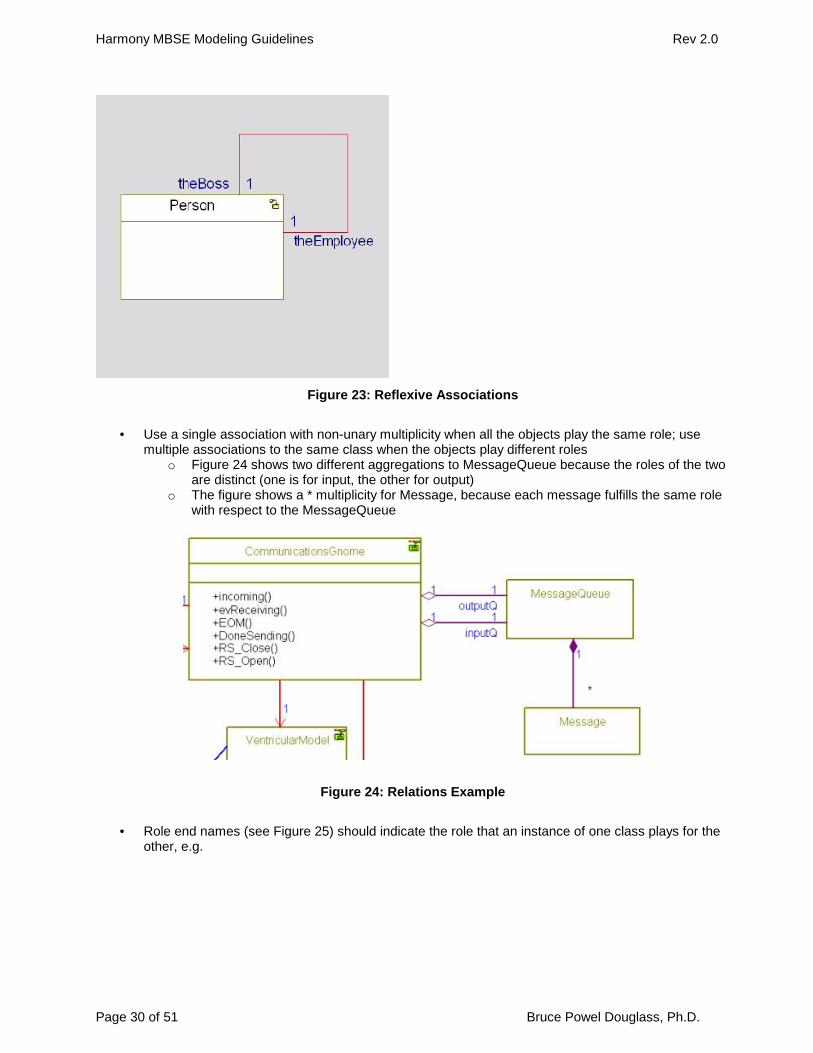
o When there are multiple associations between a pair of classeso When the association is to and from the same class (see Figure 23).
Harmony MBSE Modeling Guidelines Rev 2.0
Page 30 of 51 Bruce Powel Douglass, Ph.D.
Figure 23: Reflexive Associations
Use a single association with non-unary multiplicity when all the objects play the same role; usemultiple associations to the same class when the objects play different roles
o Figure 24 shows two different aggregations to MessageQueue because the roles of the twoare distinct (one is for input, the other for output)
o The figure shows a * multiplicity for Message, because each message fulfills the same rolewith respect to the MessageQueue
Figure 24: Relations Example
Role end names (see Figure 25) should indicate the role that an instance of one class plays for theother, e.g.

Harmony MBSE Modeling Guidelines Rev 2.0
Page 31 of 51 Bruce Powel Douglass, Ph.D.
Figure 25: Role Names Example
Most associations should be unidirectionalo Most associations model a client-server relation with the client being able to navigate to the
server, but not vice versa.o Early models may use bidirectional associations when the direction of message flow isn’t
clear but later models should resolve most of these into unidirectional associations Use association classes when the association is rich, either in information or behavior, e.g.
o Socketo Marriage
If the association class must participate in relations, then use a (regular) block instead of anassociation class, and draw associations from it to the two other participant classes
o Note: This is the most common design realization of association blocks anyway
Figure 26: Association Class
Use rectilinear lines for association (including aggregation and composition) and straight lines forgeneralization

Harmony MBSE Modeling Guidelines Rev 2.0
Page 32 of 51 Bruce Powel Douglass, Ph.D.
Use composition only when you want to enforce creation and destruction semantics, e.g. the wholeis responsible for creation and destruction of the part
Composition is a relationship between blocks (i.e. specifications);a structured block with parts is arelation between a block and object roles that specify it (i.e. block and part)
Minimize use of dependency relationo When used, use stereotypes to classify the dependency (e.g. bind, friend, etc)o For requirements traceability, use the «trace» dependency (if done in the model rather than
in a separate requirements traceability tool) Use generalization only when the specialized block extends and/or specializes the base block Don’t use generalization to indicate object roles
o “Up button” and “Down button” are not different subclasses – difference is in usage not inspecification
o Indicate role either as an association end role or as a part name inside a structured class Use generalization and parameterization properly
o Use generalization when you want the subclass to work on exactly the same data types butyou want the behaviors on that data to work differently
o Use parameterization (“templates” in C++ or “generics” in Ada) when you want exactly thesame behavior but want it to operate on different data types
Figure 27: Parameterization and Generalization
Graphically position subclasses and bound parameterized blocks below their base elements asshown in Figure 28.

Harmony MBSE Modeling Guidelines Rev 2.0
Page 33 of 51 Bruce Powel Douglass, Ph.D.
Figure 28: Role Names Subclasses Example
3.7 Sequence Diagram Guidelines As much as possible, arrange the lifelines to make messages go from left to right, as shown in
Figure 29. Use horizontal lines for synchronous messages and slanted lines for asynchronous Use execution occurrences (“activation bars”) sparingly and only for synchronously invoked
messages Add comments to the sequence to describe why steps are being taken and to describe parallel
activities not shown in the messages To show scenarios at different levels of abstraction, use a structured class on the abstract scenario,
decompose the lifeline on a nested diagram to show how parts of the structured class interact

Harmony MBSE Modeling Guidelines Rev 2.0
Page 34 of 51 Bruce Powel Douglass, Ph.D.
Figure 29: Sequence Diagram Example
To shorten long scenario, wrap up sets of related messages into a referenced interaction fragment,as shown in Figure 30.
Figure 30: Interaction Fragment
To reuse sets of messages, use a referenced interaction fragment Name messages the same as the operations or events they represent or invoke For special semantics use relevant interaction fragment operators, e.g.
o Loopo Parallelo Opt (optional) for “if”

Harmony MBSE Modeling Guidelines Rev 2.0
Page 35 of 51 Bruce Powel Douglass, Ph.D.
o Alt (alternative) for “select case”
Figure 31: Loop Operator

Harmony MBSE Modeling Guidelines Rev 2.0
Page 36 of 51 Bruce Powel Douglass, Ph.D.
Figure 32: Opt and Alt Operators
3.8 State Diagram Guidelines State diagrams should be used to specify reactive (i.e. “reacts to events”) behavior for blocks and
use cases, including blocks at different levels of abstraction (e.g. systems and subsystems) Use a statechart to model behavior of classifiers when that behavior
o is event driven oro is modal, i.e. the behavior differs depending on state
Always, at every level of nesting, indicate the default state State diagrams may be either asynchronous (asynchronous event-driven) or synchronous (call-
driven) but not usually botho Great care must be taken with state machines with both synchronous and asynchronous
triggers to avoid race conditions
3.8.1 States Use names for states that come from the problem vocabulary (domain) Use composite states when one transition exiting the composite applies to all nested states or when
the composite state logically contains the nested states (e.g. note the evEOS event fromParsingNumber state in Figure 33).

Harmony MBSE Modeling Guidelines Rev 2.0
Page 37 of 51 Bruce Powel Douglass, Ph.D.
Figure 33: Nested States
Use submachines to simplify complex state machines such as shown in the following sets offigures. Figure 34 shows a complex statechart with 3 levels of abstraction before it is decomposedinto nested submachines. Figure 35 through Figure 37 show exactly the same statechartdecomposed into a set of layered submachines.

Harmony MBSE Modeling Guidelines Rev 2.0
Page 38 of 51 Bruce Powel Douglass, Ph.D.
Figure 34: Complex statechart before decomposition into submachines
Figure 35: Statechart decomposed into submachines – level 0

Harmony MBSE Modeling Guidelines Rev 2.0
Page 39 of 51 Bruce Powel Douglass, Ph.D.
Figure 36: Statechart decomposed into submachines – level 1

Harmony MBSE Modeling Guidelines Rev 2.0
Page 40 of 51 Bruce Powel Douglass, Ph.D.
Figure 37: Statechart decomposed into submachines – level 2
Use and-states when the order of execution of actions between the and-states is irrelevant When and-states must synchronize, use one or more of the four primary methods
o Broadcast events – each event is processed independently by all active and-states This is logically equivalent to each and-state receiving its own copy of the event
sent to the objecto Propagated events – an action is executed when an event is executed by one and-state,
and this event is consumed in the next modeling step by another and-state, enforcing aspecific order of transition execution E.g. /GEN(evStep2);
o Guards – guards may be used to ensure that another and-state is in a particular state usingthe IS_IN() operator, e.g. IS_IN(DOOR_CLOSED)
o Common attributes – the scope of a state machine is the object, so all object features are“visible” to all and-states
o See Figure 38 for examples of and-state synchronization

Harmony MBSE Modeling Guidelines Rev 2.0
Page 41 of 51 Bruce Powel Douglass, Ph.D.
Figure 38: Coordinating And-States
Separate and-states into different objects when the features they use don’t significantly overlapo If and-states manipulate different attributes of the object and use different services of the
object, separate them into multiple objects with associations Use of and-states in use cases is not uncommon, but it is relatively rare to find them in the class
model. Figure 39 is a use case statechart with and-states.

Harmony MBSE Modeling Guidelines Rev 2.0
Page 42 of 51 Bruce Powel Douglass, Ph.D.
Figure 39: Use Case Statechart
3.8.2 Transitions Use null-triggered events when you add a state for the purpose of forcing closure of the state
machine stepo This is typically done to force action completion so that the result of those actions can be
used in guards

Harmony MBSE Modeling Guidelines Rev 2.0
Page 43 of 51 Bruce Powel Douglass, Ph.D.
Figure 40: Forcing action closure
Pay attention to action placemento Add actions to state entry only when the actions should be executed whenever the state is
entered regardless of which transition is takeno Add actions to state exit only when the actions should be executed whenever the state is
exited regardless of which transition is takeno Add actions to transitions when the above conditions are not met
In the presence of and-states, avoid race conditionso Race conditions are defined to be when a computational result depends on a specific order
of execution, but that order is not knowableo Race conditions occur when the same event is processed in simultaneously active and-
states and Incompatible target states are specified, or Actions on the transitions manipulate the same attributes, or Incompatible actions are executed
o See Figure 41 for an example of an avoidable race condition

Harmony MBSE Modeling Guidelines Rev 2.0
Page 44 of 51 Bruce Powel Douglass, Ph.D.
Figure 41: Race Condition in And-States
3.8.3 Actions Actions are run-to-completion, therefore actions should generally have a short execution time Actions may be direct attribute manipulations, operations defined on the class, or operations defined
on classes to which the current class has an association Complex actions should be modeled as operations; those operations can then be specified using
activity diagramso E.g rather than “/x = foo(z); y = sin(x)^2 – tan(x); z = hsin(x + y);”, wrap the set of actions in
to an operation and invoke it “/computeZ();” Simple actions may be direct action language statements to manipulate attributes of the object
o E.g. ev1/ x = sin(y) + cos(z);
3.8.4 Guards Guards should not have side-effects
o In C, C++, or Java, “x = 0” should not be used as a guard; “x == 0” would be better Guards on transition segments exiting conditional connectors should have non-overlapping
conditionso For example, “[x>0]” and “[x>10}” would not be good guards from the same conditional
connector as if x==20, both guards would evaluate to TRUE Don’t use the result of actions in guards on the same transition
o Guards are evaluated prior to the execution of actionso See Forcing Closure rule above
Use an [else] guard when the event triggering the transition must always be handled If you use a choice point, you must always have an [else] guard on an exiting transition

Harmony MBSE Modeling Guidelines Rev 2.0
Page 45 of 51 Bruce Powel Douglass, Ph.D.
3.8.5 SubmachinesA submachine is a set of nested states that are placed in a separate diagram to decrease the visualcomplexity of a state machine.
Remember that submachines are “syntactic sugar” only – the submachine is still logically a part ofthe containing statemachine; submachine merely aid in visualization of complex state machines
Use submachines to manage complexityo when a composite state is part of a complex state machine, that composite state can be
decomposed on a separate state diagram (submachine)o recommended when there are few, if any, non-default transitions
Use exit and entry points only when non-default transitions are usedo If there are more than a very small number of non-default transitions, it is recommended not
to decompose the nested state into a submachine See State Guidelines and Figure 35 through Figure 37, above.
3.9 Activity Diagram Guidelines Use activity diagrams to model behavior that is flow (rather than event-) based such as algorithms
or when modeling behavior that is continuous in time or value such as continuous pressure on apedal
Model algorithmic behavior (flow of control) with activity diagramso Operations can be specified with activity diagrams
Always indicate starting activity or action state Use forks and joins to model concurrency in activity diagrams Use swim lanes to allocate activities to classifiers Transitions should activate upon completion of the previous activity rather than the reception of an
event Use guards only on transitions exiting a condition or branch point Complexity in activity diagrams is managed by decomposition
o Use activity submachines to manage complex activity diagrams, oro Decompose the operation into multiple operation calls
Each operation can have its own activity diagram Activity diagrams and state machine should be mixed with the statechart “on top”

Harmony MBSE Modeling Guidelines Rev 2.0
Page 46 of 51 Bruce Powel Douglass, Ph.D.
Figure 42: Mixing activity diagrams and state machines
APPENDIX A – RHAPSODY ACTION LANGUAGE
Basic syntaxThe following appendix provides a brief introduction to Rhapsody’s action language. Action languagestatements are used in five primary places:
In operation implementation bodies (Open the Features dialog for the operation, and select theImplementation pane), e.g.
o For (j=0;j<10;j++) {x += foo(j);}
As actions on statecharts eithero As state entry actionso As state exit actionso As transition actions
E.g. ev1[x>=15]/foo(params->z); As guards on transitions
o E.g. [IS_IN(Closed) && (x < 10)] As action specifications in actions or activities on activity diagrams As guards on transitions in activity diagrams

Harmony MBSE Modeling Guidelines Rev 2.0
Page 47 of 51 Bruce Powel Douglass, Ph.D.
The language is case sensitive. That is, “evmove” is different from “evMove”.
Each action statement not within a guard must end with a semi-colon.
All names must start with a letter and may contain additional letters, numbers, and the underscorecharacters, but cannot contain spaces. Special characters are not permitted in names, except forunderscores (_). However, a name should never start with an underscore.
The following words are reserved and should not be used for names: asm, auto, break, case, catch, char,class, const, continue, default, delete, do, double, else, enum, extern, float, for, friend, GEN, goto, id, if,inline, int, IS_IN, IS_PORT, long, new, operator, OPORT, OUT_PORT, params, private, protected, public,register, return, short, signed, sizeof, static, struct, switch, template, this, throw, try, typedef, union,unsigned, virtual, void, volatile, while.
Assignment and Arithmetic Operators
X=1; (Sets X equal to 1)
X=Y; (Sets X equal to Y)
X=X+5; (Adds 5 to X)
X=X-3; (Subtracts 3 from X)
X=X*4; (Multiplies X by 4)
X=X/2; (Divides X by 2)
X=X%5; (Sets X to the remainder of X divided by 5)
X++; (Increments X by 1)
X--; (Decrements X by 1)
PrintingThe “cout” operator prints to the screen. Elements to be printed are separated by the “<<” operator.Text strings are surrounded by double quotes. Attributes are referenced using their names. The“endl” operator prints a carriage return. So, to print out the current value of X, use the followingcommand:
cout << “The value of X is “ << X << endl;
If the current value of X is 5, this statement prints the following message on the screen:
The value of X is 5
Comparison OperatorsX==5 (X equal to 5)
X!=5 (X not equal to 5)
Harmony MBSE Modeling Guidelines Rev 2.0
Page 48 of 51 Bruce Powel Douglass,Ph.D.
X<3 (X less than 3)
X<=3 (X less than or equal to 3)
X>4 (X greater than 4)
X>=4 (X greater than or equal to 4)
X>2 && X<7 (X greater than 2 and X less than 7
X<2 || X==7 (X less than 2 or X equal to 7)
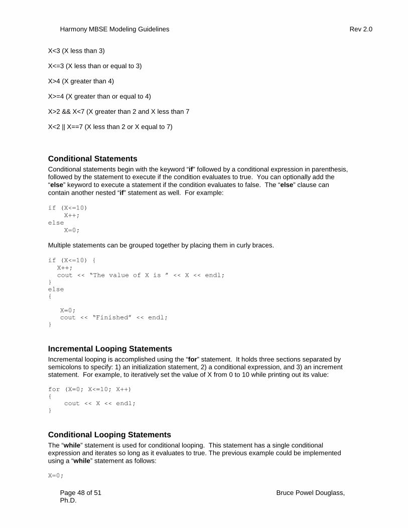
Conditional StatementsConditional statements begin with the keyword “if” followed by a conditional expression in parenthesis,followed by the statement to execute if the condition evaluates to true. You can optionally add the“else” keyword to execute a statement if the condition evaluates to false. The “else” clause cancontain another nested “if” statement as well. For example:
if (X<=10)X++;
elseX=0;
Multiple statements can be grouped together by placing them in curly braces.
if (X<=10) {X++;cout << “The value of X is ” << X << endl;
}else{
X=0;cout << “Finished” << endl;
}
Incremental Looping StatementsIncremental looping is accomplished using the “for” statement. It holds three sections separated bysemicolons to specify: 1) an initialization statement, 2) a conditional expression, and 3) an incrementstatement. For example, to iteratively set the value of X from 0 to 10 while printing out its value:
for (X=0; X<=10; X++){
cout << X << endl;}
Conditional Looping StatementsThe “while” statement is used for conditional looping. This statement has a single conditionalexpression and iterates so long as it evaluates to true. The previous example could be implementedusing a “while” statement as follows:
X=0;

Harmony MBSE Modeling Guidelines Rev 2.0
Page 49 of 51 Bruce Powel Douglass,Ph.D.
while(X<=10){
cout << X << endl;X++;
}
Invoking OperationsTo invoke an operation on a block, use the operation name followed by parenthesis. For example, toinvoke the “go” operation:
go();
If an operation takes parameters, place them in a comma-separated list. For example, to invoke the“min” operation with two parameters:
min(X,Y);
Generating EventsThe “OUT_PORT” and “GEN” keywords are used to generate events through ports. For example, tosend an event named “evStart” out the port named “p2”, issue the following statement:
OUT_PORT(p2)->GEN(evStart);
To generate an event with parameters, place them into a comma-separated list. For example, togenerate an event named “evMove” with two parameters for velocity and direction:
OUT_PORT(p2)->GEN(evMove(10,2));
NOTE: The “OPORT” keyword can be used in place of “OUT_PORT”.
Referring to Event Parameters in TransitionsThe “params” keyword followed by the “->” operator is used to reference the parameters of the eventthat caused the current transition. For example, if an event named “evMove” has a parameter named“velocity”, that parameter can be referenced using “params->velocity”. This syntax can also beembedded in statements within the action on the transition. For example,
if (params->velocity <= 5)…
Testing the Port on which an Event ArrivesThe “IS_PORT” keyword is used to test whether the event that caused the current transition arrivedthrough a specific port. For example:
if (IS_PORT(p2))…

Harmony MBSE Modeling Guidelines Rev 2.0
Page 50 of 51 © Telelogic, 2006 Bruce Powel Douglass, Ph.D.
Testing the State of a State MachineThe “IS_IN” keyword is used to test whether a state machine is in a specific state. For example, to test whetherthe state machine of a block is in a state called “Accelerating”:
if (IS_IN(Accelerating))...


![[MBSE 2021] ESA MBSE Evolution: From ESA SysML Toolbox to ...](https://static.fdocuments.us/doc/165x107/61f003bcc08c1e795d73caa3/mbse-2021-esa-mbse-evolution-from-esa-sysml-toolbox-to-.jpg)