Harley Davidson Indianapolis | Motorcycle Dealers : Indywesthd
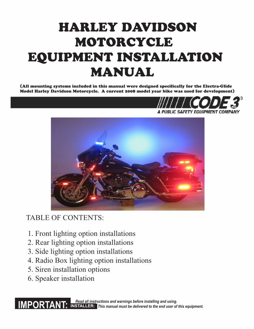
harley davidson motorcycle equipment installation manual
table of contents:
1. front lighting option installations2. Rear lighting option installations3. side lighting option installations4. Radio box lighting option installations5. siren installation options6. speaker installation
Read all instructions and warnings before installing and using. This manual must be delivered to the end user of this equipment.INSTALLER: IMPOR-IMPORTANT: INSTALLER:
(all mounting systems included in this manual were designed specifically for the electra-Glide model harley davidson motorcycle. a current 2008 model year bike was used for development)
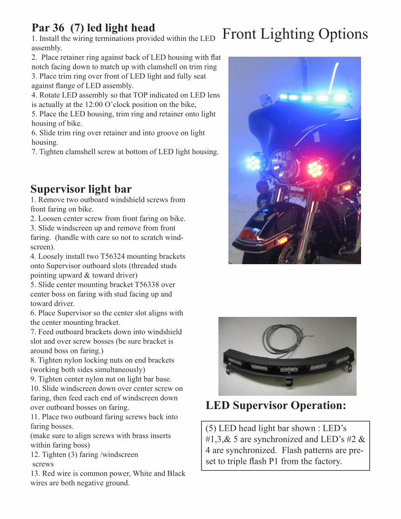
Par 36 (7) led light head1. Install the wiring terminations provided within the leD assembly.2. Place retainer ring against back of LED housing with flat notch facing down to match up with clamshell on trim ring3. Place trim ring over front of leD light and fully seat against flange of LED assembly.4. Rotate leD assembly so that toP indicated on leD lens is actually at the 12:00 o’clock position on the bike, 5. Place the leD housing, trim ring and retainer onto light housing of bike. 6. slide trim ring over retainer and into groove on light housing. 7. tighten clamshell screw at bottom of leD light housing.
Supervisor light bar1. Remove two outboard windshield screws from front faring on bike.2. loosen center screw from front faring on bike.3. slide windscreen up and remove from front faring. (handle with care so not to scratch wind-screen).4. loosely install two t56324 mounting brackets onto supervisor outboard slots (threaded studs pointing upward & toward driver)5. slide center mounting bracket t56338 over center boss on faring with stud facing up and toward driver. 6. Place supervisor so the center slot aligns with the center mounting bracket.7. feed outboard brackets down into windshield slot and over screw bosses (be sure bracket is around boss on faring.)8. tighten nylon locking nuts on end brackets (working both sides simultaneously)9. tighten center nylon nut on light bar base.10. slide windscreen down over center screw on faring, then feed each end of windscreen down over outboard bosses on faring. 11. Place two outboard faring screws back into faring bosses.(make sure to align screws with brass inserts within faring boss)12. tighten (3) faring /windscreen screws13. Red wire is common power, White and black wires are both negative ground.
front lighting options
LED Supervisor Operation:
(5) leD head light bar shown : leD’s #1,3,& 5 are synchronized and leD’s #2 & 4 are synchronized. flash patterns are pre-set to triple flash P1 from the factory.
front end side lighting options
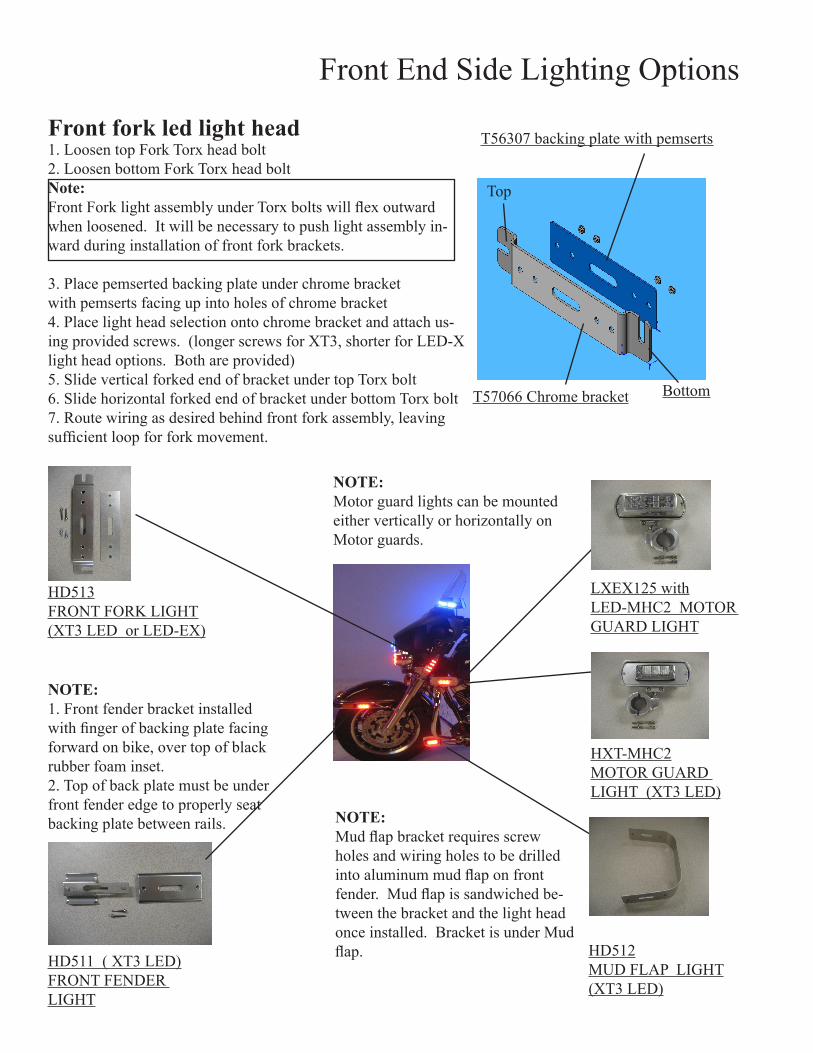
Front fork led light head1. loosen top fork torx head bolt 2. loosen bottom fork torx head bolt Note: Front Fork light assembly under Torx bolts will flex outward when loosened. It will be necessary to push light assembly in-ward during installation of front fork brackets.
3. Place pemserted backing plate under chrome bracketwith pemserts facing up into holes of chrome bracket 4. Place light head selection onto chrome bracket and attach us-ing provided screws. (longer screws for Xt3, shorter for leD-X light head options. both are provided)5. slide vertical forked end of bracket under top torx bolt6. slide horizontal forked end of bracket under bottom torx bolt7. Route wiring as desired behind front fork assembly, leaving sufficient loop for fork movement.
t56307 backing plate with pemserts
t57066 chrome bracket
top
bottom
hD513fRont foRk lIght(Xt3 leD or leD-eX)
hD511 ( Xt3 leD)fRont fenDeR lIght
lXeX125 withleD-mhc2 motoR guaRD lIght
hXt-mhc2motoR guaRD lIght (Xt3 leD)
hD512muD flaP lIght(Xt3 leD)
NOtE:motor guard lights can be mounted either vertically or horizontally on motor guards.
NOtE:Mud flap bracket requires screw holes and wiring holes to be drilled into aluminum mud flap on front fender. Mud flap is sandwiched be-tween the bracket and the light head once installed. bracket is under mud flap.
NOtE:1. front fender bracket installed with finger of backing plate facing forward on bike, over top of black rubber foam inset. 2. top of back plate must be under front fender edge to properly seat backing plate between rails.
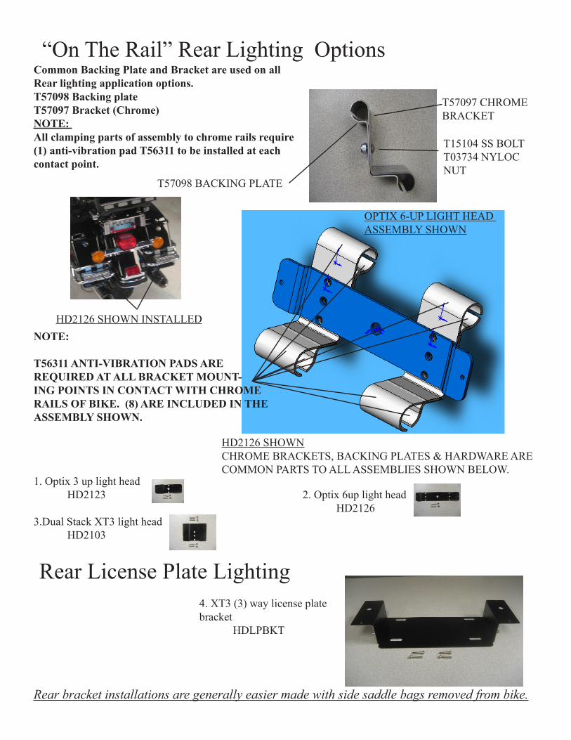
“on the Rail” Rear lighting options Common Backing Plate and Bracket are used on all Rear lighting application options.t57098 Backing platet57097 Bracket (Chrome)NOtE: All clamping parts of assembly to chrome rails require (1) anti-vibration pad t56311 to be installed at each contact point.
1. optix 3 up light head hD2123 2. optix 6up light head hD21263.Dual stack Xt3 light head hD2103
Rear bracket installations are generally easier made with side saddle bags removed from bike.
4. Xt3 (3) way license plate bracket hDlPbkt
t57097 chRome bRacket
t15104 ss boltt03734 nYloc nut
t57098 backIng Plate
NOtE:
t56311 ANtI-VIBRAtION PADS ARE REQUIRED At ALL BRACKEt MOUNt-ING POINtS IN CONtACt WItH CHROME RAILS OF BIKE. (8) ARE INCLUDED IN tHE ASSEMBLY SHOWN.
Rear license Plate lighting
oPtIX 6-uP lIght heaD assemblY shoWn
hD2126 shoWnchRome bRackets, backIng Plates & haRDWaRe aRe common PaRts to all assemblIes shoWn beloW.
hD2126 shoWn InstalleD
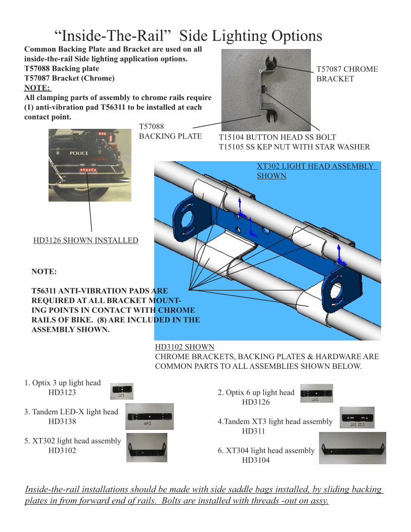
Common Backing Plate and Bracket are used on all inside-the-rail Side lighting application options.t57088 Backing platet57087 Bracket (Chrome)NOtE: All clamping parts of assembly to chrome rails require (1) anti-vibration pad t56311 to be installed at each contact point.
“Inside-the-Rail” side lighting options
1. optix 3 up light head hD3123 2. optix 6 up light head hD31263. tandem leD-X light head hD3138 4.tandem Xt3 light head assembly hD3115. Xt302 light head assembly hD3102 6. Xt304 light head assembly hD3104
Inside-the-rail installations should be made with side saddle bags installed, by sliding backing plates in from forward end of rails. Bolts are installed with threads -out on assy.
hD3102 shoWnchRome bRackets, backIng Plates & haRDWaRe aRe common PaRts to all assemblIes shoWn beloW.
Xt302 lIght heaD assemblY shoWn
NOtE:
t56311 ANtI-VIBRAtION PADS ARE REQUIRED At ALL BRACKEt MOUNt-ING POINtS IN CONtACt WItH CHROME RAILS OF BIKE. (8) ARE INCLUDED IN tHE ASSEMBLY SHOWN.
t57087 chRome bRacket
t57088 backIng Plate t15104 button heaD ss bolt
t15105 ss keP nut WIth staR WasheR
hD3126 shoWn InstalleD
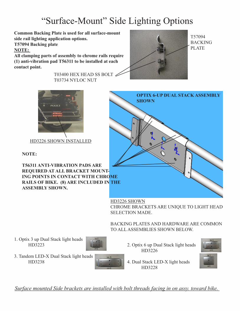
Common Backing Plate is used for all surface-mount side rail lighting application options. t57094 Backing plateNOtE: All clamping parts of assembly to chrome rails require (1) anti-vibration pad t56311 to be installed at each contact point.
1. optix 3 up Dual stack light heads hD3223 2. optix 6 up Dual stack light heads hD32263. tandem leD-X Dual stack light heads hD3238 4. Dual stack leD-X light heads hD3228
Surface mounted Side brackets are installed with bolt threads facing in on assy. toward bike.
“surface-mount” side lighting options
NOtE:
t56311 ANtI-VIBRAtION PADS ARE REQUIRED At ALL BRACKEt MOUNt-ING POINtS IN CONtACt WItH CHROME RAILS OF BIKE. (8) ARE INCLUDED IN tHE ASSEMBLY SHOWN.
OPtIX 6-UP DUAL StACK ASSEMBLY SHOWN
hD3226 shoWnchRome bRackets aRe unIQue to lIght heaD selectIon maDe.
backIng Plates anD haRDWaRe aRe common to all assemblIes shoWn beloW.
t57094backIng Plate
t03400 heX heaD ss boltt03734 nYloc nut
hD3226 shoWn InstalleD
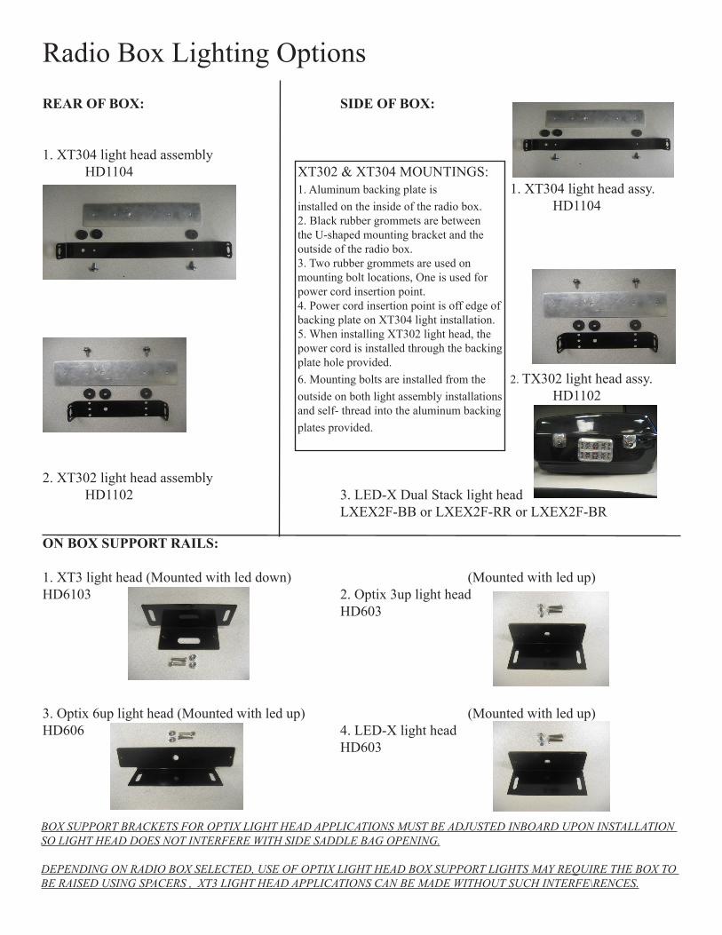
Radio box lighting options
ON BOX SUPPORt RAILS:
1. Xt3 light head (mounted with led down) (mounted with led up)hD6103 2. optix 3up light head hD603
3. optix 6up light head (mounted with led up) (mounted with led up)hD606 4. leD-X light head hD603
REAR OF BOX: SIDE OF BOX:
1. Xt304 light head assembly hD1104 Xt302 & Xt304 mountIngs: 1. aluminum backing plate is 1. Xt304 light head assy. installed on the inside of the radio box. hD1104 2. black rubber grommets are between the u-shaped mounting bracket and the outside of the radio box. 3. two rubber grommets are used on mounting bolt locations, one is used for power cord insertion point. 4. Power cord insertion point is off edge of backing plate on Xt304 light installation. 5. When installing Xt302 light head, the power cord is installed through the backing plate hole provided. 6. mounting bolts are installed from the 2. tX302 light head assy. outside on both light assembly installations hD1102 and self- thread into the aluminum backing plates provided. 2. Xt302 light head assembly hD1102 3. leD-X Dual stack light head lXeX2f-bb or lXeX2f-RR or lXeX2f-bR
BOX SUPPORT BRACKETS FOR OPTIX LIGHT HEAD APPLICATIONS MUST BE ADJUSTED INBOARD UPON INSTALLATION SO LIGHT HEAD DOES NOT INTERFERE WITH SIDE SADDLE BAG OPENING.
DEPENDING ON RADIO BOX SELECTED, USE OF OPTIX LIGHT HEAD BOX SUPPORT LIGHTS MAY REQUIRE THE BOX TO BE RAISED USING SPACERS , XT3 LIGHT HEAD APPLICATIONS CAN BE MADE WITHOUT SUCH INTERFE\RENCES.
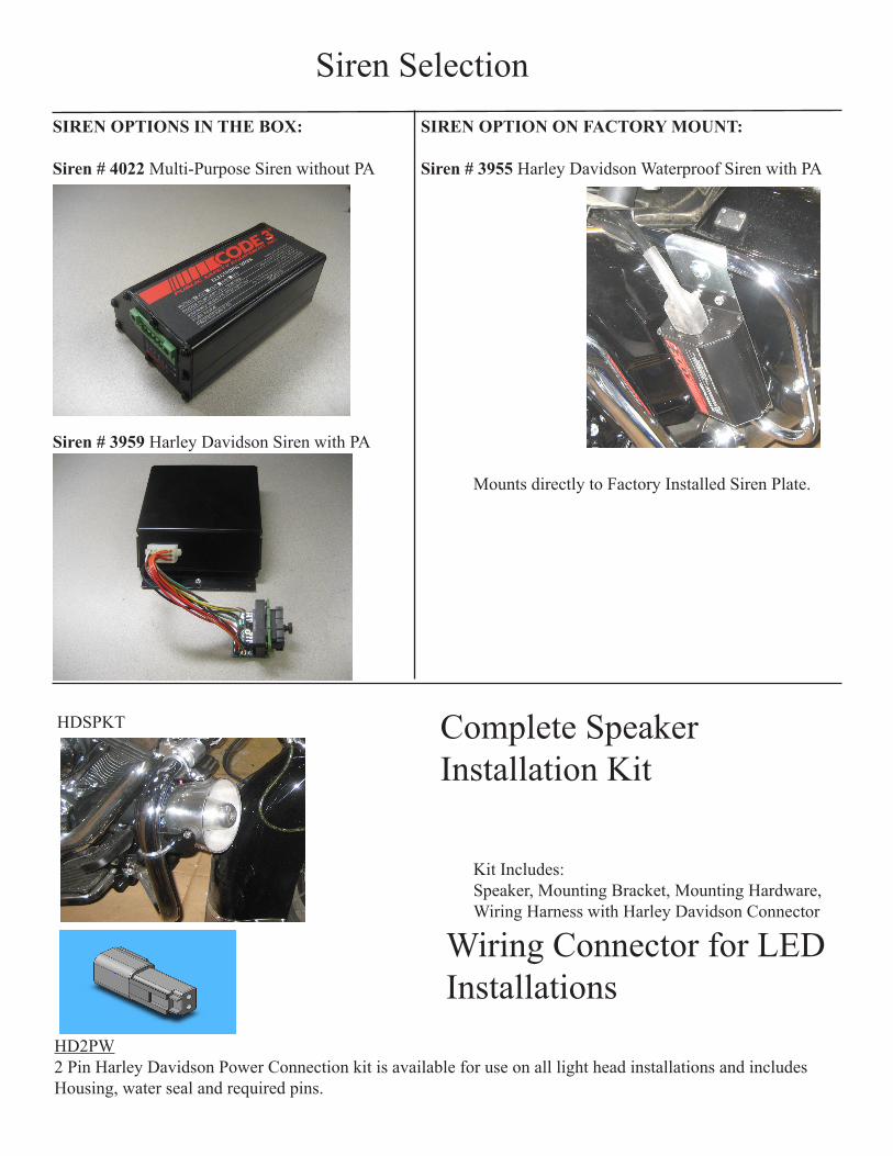
siren selection
complete speaker Installation kit
SIREN OPtIONS IN tHE BOX: SIREN OPtION ON FACtORY MOUNt:
Siren # 4022 multi-Purpose siren without Pa Siren # 3955 harley Davidson Waterproof siren with Pa
Siren # 3959 harley Davidson siren with Pa
mounts directly to factory Installed siren Plate.
hDsPkt
kit Includes: speaker, mounting bracket, mounting hardware, Wiring harness with harley Davidson connector
hD2PW2 Pin harley Davidson Power connection kit is available for use on all light head installations and includes Housing, water seal and required pins.
Wiring connector for leD Installations

NOtES:
This page provided for installation notes

NOtES:
This page provided for installation notes

NOtES:
This page provided for installation notes
Code 3® is a registered trademark of Code 3, Inc., a subsidiary of Public Safety Equipment, Inc.
PRODUCT RETURNSIf a product must be returned for repair or replacement*, please contact our factory to obtain a Return Goods Authorization Number
(RGA number) before you ship the product to Code 3, Inc. Write the RGA number clearly on the package near the mailing label. Be sure you use sufficient packing materials to avoid damage to the product being returned while in transit.
*Code 3, Inc. reserves the right to repair or replace at its discretion. Code 3, Inc. assumes no responsibility or liability for expenses incurred for the removal and /or reinstallation of products requiring service and/or repair.; nor for the packaging, handling, and shipping: nor for the handling of products return to sender after the service has been rendered.
PROBLEMS OR QUESTIONS? CALL OUR TECHNICAL ASSISTANCE HOTLINE (314) 996-2800WWW.CODE3PSE.COM
Code 3®, Inc.10986 N. Warson Road
St. Louis, Missouri 63114-2029—USAPh. (314) 426-2700 Fax (314) 426-1337
Part No. T56340 Rev. 0 06/2008©2008 Code 3, Inc
WARRANTYCode 3, ®Inc.'s emergency devices are tested and found to be operational at the time of manufacture. Provided they are installed and
operated in accordance with manufacturer's recommendations, Code 3, Inc. guarantees all parts and components except the lamps to a period of 1 year (unless otherwise expressed) from the date of purchase or delivery, whichever is later. Units demonstrated to be defective within the warranty period will be repaired or replaced at the factory service center at no cost.
Use of lamp or other electrical load of a wattage higher than installed or recommended by the factory, or use of inappropriate or inadequate wiring or circuit protection causes this warranty to become void. Failure or destruction of the product resulting from abuse or unusual use and/or accidents is not covered by this warranty. Code 3, Inc. shall in no way be liable for other damages including consequential, indirect or special damages whether loss is due to negligence or breach of warranty.
CODE 3, INC. MAkES NO OTHER ExPRESS OR IMPLIED WARRANTY INCLUDINg, WITHOUT LIMITATION, WARRANTIES Of fITNESS OR MERCHANTABILITY, WITH RESPECT TO THIS PRODUCT.
Larger wires and tight connections will provide longer service life for components. For high current wires it is highly recommended that terminal blocks or soldered connections be used with shrink tubing to protect the connections. Do not use insulation displacement connectors (e.g. 3M® Scotchlock type connectors). Route wiring using grommets and sealant when passing through compartment walls. Minimize the number of splices to reduce voltage drop. High ambient temperatures (e.g. underhood) will significantly reduce the current carrying capacity of wires, fuses, and circuit breakers. Use "SXL" type wire in engine compartment. All wiring should conform to the minimum wire size and other recommendations of the manufacturer and be protected from moving parts and hot surfaces. Looms, grommets, cable ties, and similar installation hardware should be used to anchor and protect all wiring. Fuses or circuit breakers should be located as close to the power takeoff points as possible and properly sized to protect the wiring and devices. Particular attention should be paid to the location and method of making electrical connections and splices to protect these points from corrosion and loss of conductivity. Ground terminations should only be made to substantial chassis components, preferably directly to the vehicle battery. The user should install a fuse sized to approximately 125% of the maximum Amp capacity in the supply line to protect against short circuits. For example, a 30 Amp fuse should carry a maximum of 24 Amps. DO NOT USE 1/4" DIAMETER GLASS FUSES AS THEY ARE NOT SUITABLE FOR CONTINUOUS DUTY IN SIZES ABOVE 15 AMPS. Circuit breakers are very sensitive to high temperatures and will "false trip" when mounted in hot environments or operated close to their capacity.
WARNINg!