HARDWARE REALISATION OF SELF PROPELLED ...jestec.taylors.edu.my › Vol 13 issue 1 January 2018 ›...
19
Journal of Engineering Science and Technology Vol. 13, No. 1 (2018) 083 - 101 © School of Engineering, Taylor’s Uni versity 83 HARDWARE REALISATION OF SELF PROPELLED SAFETY MONITORING SYSTEM USING CAN PROTOCOL C. R. BALAMURUGAN*, R. BENSRAJ Department of EEE, Karpagam College of Engineering, Coimbatore Department of EEE, Annamalai University, Chidambaram, India *Corresponding Author: [email protected] Abstract The automotive vehicle is the most importance in transportation. This paper discussed various safety measures that can be implemented in vehicles for safe travelling. The drawbacks that are observed in the existing system are glaring effect due to the opposite vehicle light illumination, gas leakage, short circuit in electrical wiring, high volume in horn causing noise pollution. Distance between two vehicles should be maintained certain meters to avoid accidents, unequal wheel pressure may lead to accidents, inaccurate fuel level in analog meters and high engine area temperature may cause damages to the engine. The GSM (Global System for Mobile communication) and GPS (Global Positioning System) are used to access the location during fault occurred (or) during cause of accident, it will send the information to the rescue people. These sensors are connected through Master and Slave modules and it is communicated using CAN (Controller Area Network) protocol. The simulation and experimental results show that the vehicle with a safety monitoring system provides a better safety to the persons in the vehicle and thereby accidents can be avoided. This proposed work was simulated and implemented through hardware. The observed results closely match with simulation and hardware results. Keywords: Control area network, Global positioning system, Global system for mobile communication, Vehicle, Hardware. 1. Introduction The controller area network is most commonly used in the automotive vehicle communication. The proposed work provides monitoring of various sensors to provide safety and gives alert to the persons in the vehicle and to the rescue team. Automotive electronics is a rapidly expanding area with an increasing number of
Transcript of HARDWARE REALISATION OF SELF PROPELLED ...jestec.taylors.edu.my › Vol 13 issue 1 January 2018 ›...

Journal of Engineering Science and Technology Vol. 13, No. 1 (2018) 083 - 101 © School of Engineering, Taylor’s University
83
HARDWARE REALISATION OF SELF PROPELLED SAFETY MONITORING SYSTEM USING CAN PROTOCOL
C. R. BALAMURUGAN*, R. BENSRAJ
Department of EEE, Karpagam College of Engineering, Coimbatore
Department of EEE, Annamalai University, Chidambaram, India
*Corresponding Author: [email protected]
Abstract
The automotive vehicle is the most importance in transportation. This paper
discussed various safety measures that can be implemented in vehicles for safe
travelling. The drawbacks that are observed in the existing system are glaring
effect due to the opposite vehicle light illumination, gas leakage, short circuit in
electrical wiring, high volume in horn causing noise pollution. Distance
between two vehicles should be maintained certain meters to avoid accidents,
unequal wheel pressure may lead to accidents, inaccurate fuel level in analog
meters and high engine area temperature may cause damages to the engine. The
GSM (Global System for Mobile communication) and GPS (Global Positioning
System) are used to access the location during fault occurred (or) during cause
of accident, it will send the information to the rescue people. These sensors are
connected through Master and Slave modules and it is communicated using
CAN (Controller Area Network) protocol. The simulation and experimental
results show that the vehicle with a safety monitoring system provides a better
safety to the persons in the vehicle and thereby accidents can be avoided. This
proposed work was simulated and implemented through hardware. The
observed results closely match with simulation and hardware results.
Keywords: Control area network, Global positioning system, Global system for
mobile communication, Vehicle, Hardware.
1. Introduction
The controller area network is most commonly used in the automotive vehicle
communication. The proposed work provides monitoring of various sensors to
provide safety and gives alert to the persons in the vehicle and to the rescue team.
Automotive electronics is a rapidly expanding area with an increasing number of

84 C. R. Balamurugan and R. Bensraj
Journal of Engineering Science and Technology January 2018, Vol. 13(1)
Abbreviations
ADC Analog to Digital Converter
AFHAS Automatic Front Headlight Adjustment System
CAN Controller Area Network
DC Direct Current
DCMs Digital Clock Manager
ECU Electronic Controller Control
EEPROM Electrically Erasable Programmable Read Only Memory
GPS Global Positioning System
GS Ground-Scattering
GSM Global System for Mobile communication
IR Infra-Red
LCD Liquid Crystal Display
LDR Light Dependent Resister
MCU Microcontroller Unit
MPPT Maximum Power Point Tracking
OW Optical Wireless
PIC Programmable Interface Controller RMS
RMS Root Mean Square
RTU Remote Terminal Unit
SUV Sports Utility Vehicle
TPMS Temperature Pressure Monitoring Systems
VCN Vehicle Control Networks
safety, driver assistance, and infotainment devices. Current vehicles generally
employ a number of different networking protocols to integrate the systems into
the vehicle. The introduction of large numbers of sensors to provide driver
assistance applications and the associated high-bandwidth requirements of these
sensors has accelerated the demand for faster and more flexible network
communication technologies within the vehicle. This proposed system includes
seven safety measures.
These safety measures are the most common reasons for road accidents during
day and night time driving. In this proposed system, the included measures are,
the first one is to reduce night time driving accidents due to opponent headlight
illumination by AFHAS (Automatic Front Headlight Adjustment System).
Because most of the accidents arise at night time driving. The second one is to
reduce the short circuit faults at the vehicle wiring connections. The third one is to
detect gas leakage and prevention. The fourth one is to monitor the temperature
near engine location. The fifth one is to automatically adjust horn volume for
respective surroundings. The sixth one is to display accurate fuel level and the
seventh is monitoring the wheel pressure. Here some literature review is made for
implementing proposed work. Kim et al. [1] reported a new methodology for the
optimal Vehicle Control Networks (VCN) design. The VCN design was rest
denned as the temporal and spatial joint optimization problem, and some of the
challenges in solving the problem were presented. To tackle the challenges, an
analytical model for examining the fundamental characteristics of the problem
was derived. A repeated matching-based fast solution method was next provided
to optimize the VCN design. Yim designed a preview controller method for
rollover prevention has been proposed. Differential braking and active suspension
Hardware Realisation of Self Propelled Safety Monitoring System . . . . 85
Journal of Engineering Science and Technology January 2018, Vol. 13(1)
have been adopted as actuators. Under the assumption that the steering input is
preview able, the rollover prevention controller has been designed with LQ SOF
preview control [2].
Hock et al. [3] developed a wireless controller area network using low cost
microcontroller. The system is low cost and low power consumption for CAN
application in order to receive data such as velocity, temperature and batteries
power from Maximum Power Point Tracking (MPPT). Jankovic et al. [4]
approached the CAN based monitoring the vehicles mechatronics systems which
can significantly reduce time for vehicle instrumentation and enable development
engineers to conduct testing in already existing vehicle before making the prototype
of the new vehicle or system under development. Guo and Yue [5] investigated a
control design for the platoon of automated vehicles whose sensors have limited
sensing capability. A novel hybrid platoon model was established, in which actuator
delay (e.g., the fuelling and braking delay) and the effect of sensing range limitation
are involved. Ramya and Palaniappan [6] designed an embedded system for a
vehicle cabin, which senses the gases like carbon-monoxide and oxygen and
displayed at each and every second. If the level of the CO increases than the normal
level (30 ppm) or the level of the oxygen decreases than the normal level (19%), an
alarm strikes automatically and also ventilation is provided immediately. A warning
message is sent to the authorized user via GSM.
Higgins et al. [7] implemented a simple linearly scalable 1-W infrared (IR)
transmitter, which is centrally located on the ceiling of a sports utility vehicle
(SUV), and for 15 passenger configurations, an analysis into the received power,
power deviation, minimum bandwidth, and maximum root-mean-square (RMS)
delay spread is provided for the regions of the vehicle most likely to benefit from
the deployment of intra vehicle optical wireless (OW) communication system.
Kwon et al. [8] proposed a new geometry-based channel model for wide-band
polarized body area network channels consisting of four propagation modes:
cylindrical-surface-scattering (CSS) for above ground off-body scattering, body-
scattering (BS) for body diffracted and on-body scattering, ground-scattering
(GS), and line-of-sight [8]. Raibagi et al. [9] focuses on building a user-friendly
device that specializes in detecting intrusions besides doing close range obstacle
detection. Automobile safety can be improved by anticipating a crash before it
occurs and thereby providing additional time to deploy safety technologies.
Reddy et al. [10] developed an advanced Automobile Safety Information
System (SMART). By using MEMS accelerometer and GPS tracking system we
can get the information of accidental occurrence through GSM module. MEMS is
a Micro electro mechanical sensor which is a high sensitive sensor and capable of
detecting the tilt. The device is capable of performing all the tilt functions like
forward, reverse, left and right directions. Elbert et al. analysed the globally
optimal engine ON/OFF conditions are derived analytically [11]. It is
demonstrated that the optimal engine ON/OFF strategy is to switch the engine on
if and only if the requested power exceeds a certain non-constant threshold. By
iteratively computing the threshold and the power split using convex
optimization, the optimal solution to the energy management problem is found.
Joerer et al. [12] defines a collision probability estimation scheme that allows
assessment of the criticality of an intersection approach based on exchanged
beacons, such as CAMs or BSMs. Given information about two approaching

86 C. R. Balamurugan and R. Bensraj
Journal of Engineering Science and Technology January 2018, Vol. 13(1)
vehicles (such as their current position and speed), we are able to derive potential
future trajectories and calculate the probability of a crash.
Kachroo presents the overall framework for high performance vehicle streams
that integrates the transportation and the communication layered architectures
together [13]. It shows the process in establishing an infrastructure for high-
performance vehicles and the theoretical development and deployment of
cooperative adaptive cruise control (CACC) for heterogeneous vehicles that is
integrated with lateral control. Song proposed a feature points are extracted using
an improved Moravec algorithm [14]. A specially designed template is used to
track the feature points through the image sequences. Then, trajectories of feature
points can be obtained, whereas unqualified track trajectories are removed using
decision rules. Finally, the vehicle behaviour analysis algorithms are applied on
the track trajectories for traffic event detection. Deng and Zhang focuses on
technologies still can’t prevent the traffic accident very well; this brings new
study on the active safety technology based on various factors of traffic accidents
[15]. It focuses on how to prevent the collision and accidents and look on the
human condition and road condition monitoring.
Kim et al. [16] developed a novel tire-road friction coefficient estimation
method based on 6-DoF acceleration measurement was proposed and validated
under longitudinal emergency braking manoeuvres. Experimental results
indicated that tire-road friction coefficient could be estimated by the proposed
method accurately in real-time during longitudinal emergency braking, and its
relation to tire slip was consistent with the anticipated physical trends. Liu et al.
focused on improving positioning accuracy in vehicular networks using GPS
pseudo range measurements [17]. Two algorithms, namely WLS-DD and
DLEA, are proposed to enable the cooperative positioning. An extensive
simulation study demonstrates that the proposed solutions can effectively
improve the positioning accuracy under a variety of conditions. Belyaev et al.
[18] proposed a low-complexity unequal packet loss protection and rate control
algorithms for a scalable video coding based on the three-dimensional discrete
wavelet transform. IEEE 802.11p communication technology makes it possible
to introduce new automotive applications, which make use of broadband
vehicle-to-vehicle and vehicle-to-roadside connectivity. We have developed and
evaluated a new surveillance system aimed at improving public transport
security and road traffic control.
Shih and Tsai proposed a convenient indoor vision-based parking lot system
using wide-angle fish eye-lens or catadioptric cameras [19]. This is easy to set up
by a user with no technical background. Easiness in the system setup mainly
comes from the use of a new camera model that can be calibrated using only one
space line without knowing its position and direction, as well as from the
allowance of convenient changes in detected parking space boundaries. Căilean,
and Dimian [20] focused on the design of the VLC sensors intended for vehicular
communication applications, offering a review of the solutions found to mitigate
the effect of the problematic conditions. Furthermore, summarizes these solutions
and proposes an environmental adaptive VLC receiver that would be capable to
optimally adjust its settings in order to maximize the communication efficiency,
but without affecting the communication robustness to noise. The literature
survey reviles some recent papers related to area of work on automotive safety
and monitoring system.
Hardware Realisation of Self Propelled Safety Monitoring System . . . . 87
Journal of Engineering Science and Technology January 2018, Vol. 13(1)
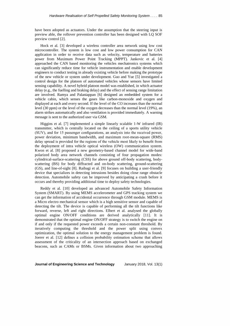
2. CAN Architecture and Protocol
The Controller Area Network is a method of communication between various
electronic devices like lighting control, air conditioning, central locking, gas
monitoring, and distance monitoring etcm embedded in automobile. Robert
Bosch in 1983 discussed how to improve the quality of automobiles and
thereby making them more reliable, safe and fuel efficient. CAN provide a
mechanism which is incorporated in the hardware and the software by which
different electronic modules can communicate with each other using a
common cable. Figure 1 shows the CAN protocol architecture and Fig. 2
shows the Bus architecture of CAN protocol.
Fig. 1. Controller area network architecture.
Fig. 2. Controller area network bus.
3. Master and Slave Module
In this proposed work the automotive vehicle safety measures are monitored and
alerts the user through message during abnormal conditions and during

88 C. R. Balamurugan and R. Bensraj
Journal of Engineering Science and Technology January 2018, Vol. 13(1)
emergency periods like accidents. The proposed system contains PIC 16f877A
microcontroller, various sensors and CAN Protocol that communicates with the
PIC microcontrollers. The sensors are connected in two microcontrollers and it is
named as Master and Slave. The two microcontrollers are communicating using
CAN protocol which is a two-wire serial communication.
The various sensors used for measuring the parameters are
a) Temperature sensor for monitoring engine temperature.
b) Digital fuel level sensor for monitoring accurate fuel level.
c) RFID for automatic horn volume adjustment.
d) Tire pressure monitoring sensor (TPMS) for monitoring pressure in the tire.
e) Current sensor for monitoring short circuit fault detection.
f) Gas leakage detection using gas sensor.
g) LDR for automatic headlight brightness adjustment during night time travelling.
h) IR sensor for distance monitoring to maintain a safer distance.
i) GPS and GSM used for sending alert message to the rescue persons during
accident and emergency situations.
Figure 3 shows the block diagram of the proposed work. The PIC
microcontrollers are named as Master and Slave. All the sensors are connected to
master and slave unit. These systems provide the monitoring and alert system for
automotive vehicles. The LCD and Buzzer are used to display the current sensor
information and buzzer during abnormal conditions.
Fig. 3. Proposed block diagram.
3.1. Master module
In Master module, PIC 16f877A microcontroller and sensors are connected
through I/O ports. The data are transferred using serial communication. The types
of sensor used in the master module are (a) GSM, (b) GPS, (c) IR Sensor, (d) Gas
leakage sensor-MQ4, (e) Fuel level sensor, and (f) Accident detection switch.

Hardware Realisation of Self Propelled Safety Monitoring System . . . . 89
Journal of Engineering Science and Technology January 2018, Vol. 13(1)
(a) GSM
The GSM is the Global System for Mobile Communication. It is commonly used
for transmitting the messages from one device to other mobile devices. GSM is
used to send the alert message during abnormal conditions and during occurrence
of accident to the rescue persons. Figure 4 show the GSM module.
Fig. 4. GSM module.
(b) GPS
GPS is the Global Positioning System which is mainly used to detect the latitude
and longitude of the particular location. During the abnormal changes in sensors
and on the accident period, it detects the location and sends the information to the
PIC microcontroller. This information is used by rescue persons to easily finding
the exact location. Figure 5 shows the GPS module.
(c) IR sensor
The IR sensor is operating during the object detection when the IR signal reflects
back to the sensor. The distance between two vehicles should maintain 10 m and
above, if it is lesser there may be chance of accidents or damage to the vehicle.
Figure 6 shows the IR sensor. The IR sensor placed in the vehicle continuously
monitors the distance and it alerts when the distance is below 10 m in range.
(d) Gas sensor MQ4
Many of the vehicles use GAS as an alternative energy for driving the vehicle.
GAS leakage in vehicle may cause severe damage to the vehicle. Figure 7 shows
the MQ4 gas sensor. The MQ4 gas sensor is used to monitor the leakage of gas
and if there is any leakage it alerts the driver and sends the message to the rescue
person during the abnormal condition.
(e) Fuel level sensor
The analog fuel level sensors which are commonly used in automotive vehicle are
inaccurate and it does not show exact fuel value. This can be overcome by using
digital fuel level sensor.

90 C. R. Balamurugan and R. Bensraj
Journal of Engineering Science and Technology January 2018, Vol. 13(1)
(f) Accident detection switch
The emergency or accident situation can be occurred any time, during this period
the persons inside the vehicle cannot access the outside rescue persons for help so
this can be overcome by placing an accident alert switch which sends the accident
alert along with the location of the vehicle to the rescue persons.
Fig. 5. GPS module. Fig. 6. IR module.
Fig. 7. Gas sensor module.
3.2. Slave module
The slave module contains PIC 16f877A microcontroller and sensors, which are
communicating using serial communication. The sensors that are used are
(a) TPMS, (b) LDR, (c) Temperature sensor - LM35, (d) Current sensor -
CT1270, and (e) RFID - EM18.
(a) TPMS
The Tire Pressure Monitoring Sensor is used to monitor the air pressure in the
tires. The uneven air pressure may cause the performance poor and increase the
heat in the wheel, Due to this it may leads to accidents.
(b) LDR
The LDR is the Light Dependent Resistor which is used to adjust the brightness
of the light so that the vehicle can be easily driven in night time. The brightness of
the light is adjusted by varying the LDR value.
(c) Temperature sensor- LM35
The temperature sensor used here is LM35.It is used to monitor the temperature
of the engine. The operating range of LM35 is from 0’C – 100 ‘C. In this
proposed work the temperature limit for normal value is set to 35’C.If the

Hardware Realisation of Self Propelled Safety Monitoring System . . . . 91
Journal of Engineering Science and Technology January 2018, Vol. 13(1)
temperature exceeds the limit it warns the driver by indicating a beep sound
through buzzer and sends the message to the rescue person about the abnormal
changes in the temperature. Figure 8 shows the LM35 temperature sensor.
(d) Current sensor - CT1270
The current measurement is more important in the electrical wirings in the
vehicle. Figure 9 shows the current sensor. If there is any fault in wiring it may
cause damages to the circuit in vehicles. The current sensor used in this proposed
work is used to monitor the current level of a DC motor which is 1 Amps in
rating. If there is any change or no power supply is detected in current sensor it
alerts the driver.
Fig. 8. Temperature sensor. Fig. 9. Current sensor module.
(e) RFID – EM18
The RF transmitter and Receiver are the EM18 receiver and RFID tag for
transmitter. Figure 10 shows RFID transmitter and receiver. The main objective
of this sensor is receiving the magnetic signal whenever the tag is placed near by
it and changes the mode of operation according to the condition. This sensor
is used for changing the volume of the vehicle according to area zone and to
reduce the noise pollution.
Fig. 10. RFID transmitter and receiver.
4. Simulation Results
The proposed work can be simulated by using proteus simulation tool. Figure 11
shows the simulated proposed work in the proteus tool.

92 C. R. Balamurugan and R. Bensraj
Journal of Engineering Science and Technology January 2018, Vol. 13(1)
In this simulation, the values of the sensors are taken by using ADC input and
it is processed in microcontroller. The sensors which are used in simulation are
temperature sensor, current sensor, luminance sensor LDR, gas sensor, digital fuel
sensor and tire pressure sensor. The output of the Master and Slave modules are
connected through the CAN protocol and the output is taken from the RS232 port
to the virtual terminal. The simulation of the proposed work provides the required
output and the proposed work can be implemented through hardware. The
following parameters are used for the simulation. Output of each sensor is
monitored through the LCD display. The sensors operate in two ways during
normal and abnormal conditions.
Fig. 11. Proposed simulation circuit.
4.1. Master during normal condition
Table 1 shows the simulation results of the master module under normal condition
for temperature, gas and luminance variations.
Table 1. Master module during normal condition.
Sensors Range LED Motor Intensity
Temp sensor Below 30 D1-OFF - -
Gas Sensor Below 30 D2- OFF OFF
Luminance sensor Below 92 - - Low
Hardware Realisation of Self Propelled Safety Monitoring System . . . . 93
Journal of Engineering Science and Technology January 2018, Vol. 13(1)
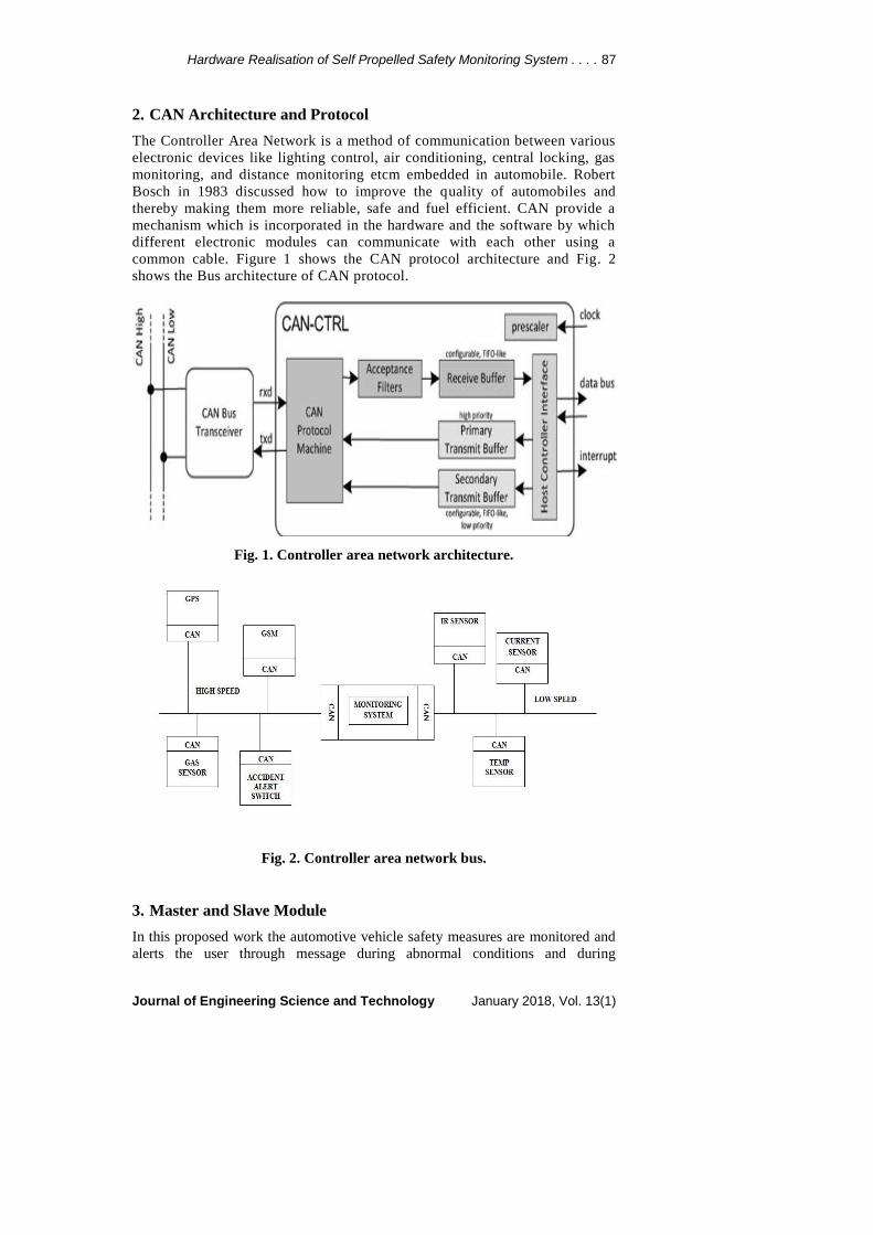
a) Temperature value
Figure 12 represents the temperature setting during normal condition. The sensor
D1 is used to measure the temperature of the master unit.
Fig. 12. Temperature during normal.
b) Front light adjustment
Figure 13 shows the front light adjustment for short range. The light dependent
resistor is used to sense the distance.
Fig. 13. Luminance during short range.
c) Gas level
The sensor D2 is used to sense the gas level. Figure 14 displays the gas level.
Fig. 14. Normal gas level.
4.2. Master during abnormal condition
Table 2 displays the simulation results of the master module under abnormal
condition for temperature, gas and luminance variations.
Table 2. Master during abnormal condition.
Sensors Range LED Motor Intensity
Temp. sensor Above 30 D1-ON - -
Gas Sensor Above 30 D2-ON ON
Luminance sensor Above 92 - - High
a) Temperature
Figure 15 represents the temperature setting during abnormal condition. The
sensor D1 is used to measure the temperature of the master unit.

94 C. R. Balamurugan and R. Bensraj
Journal of Engineering Science and Technology January 2018, Vol. 13(1)
Fig. 15. Temperature during abnormal.
b) Front light adjustment
Figure 16 shows the front light adjustment for short range. The light dependent
resistor is used to sense the distance. The LCD display shows the exact range of
front light.
Fig. 16. Luminance during long range.
c) Gas level
The sensor D2 with window motor is used to sense the gas level. Figure 17
displays the gas level.
Fig. 17. Gas leakage detected.
4.3. Slave during normal condition
Table 3 shows the simulation results of the slave module under normal condition
for fuel, current, RFID and Wheel pressure variations.
Table 3. Slave during normal condition.
Sensors Range LED Zone
Fuel sensor Above 15 ltr D3 - OFF -
Current Sensor Above .32 Amps D4 - OFF
RFID sensor Above 30 Mtr - General
Wheel Pressure Sensor Above 30 D5 - OFF

Hardware Realisation of Self Propelled Safety Monitoring System . . . . 95
Journal of Engineering Science and Technology January 2018, Vol. 13(1)
a) Fuel level
The fuel sensor D3 is used sense the level of the fuel under normal condition.
Figure 18 displays the fuel sensor output.
Fig. 18. Normal fuel level.
b) Current sensor
The current sensor D4 is used sense the amount of current flow under normal
condition. Figure19 displays the current sensor output.
Fig. 19. Normal current.
c) RFID sensor
The RFID sensor is used sense the zone under normal condition. Figure20 shows
the RFID output.
Fig. 20. General zone.
d) Wheel pressure sensor
The D5 sensor is used sense the pressure of the wheel under normal condition.
Figure 21 shows the wheel pressure sensor output.
Fig. 21. Normal wheel pressure.
4.4. Slave during abnormal condition
Table 4 shows the simulation results of the slave module under abnormal
condition for fuel, current, RFID and Wheel pressure variations. Figures 22 (a) to
(d) show the output for slave during abnormal condition.

96 C. R. Balamurugan and R. Bensraj
Journal of Engineering Science and Technology January 2018, Vol. 13(1)
Table 4. Slave during abnormal condition.
Sensors Range LED Zone
Fuel sensor Below15 ltr D3 - ON -
Current Sensor Below .30 Amps D4 - ON
RFID sensor Below 30 Mtr - Hospital/ School
Wheel Pressure Sensor Below 30 D5 - ON
a) Normal fuel level b) Normal current
c) School zone and hospital zone d) Abnormal wheel pressure
Fig. 22. Output for slave during abnormal condition.
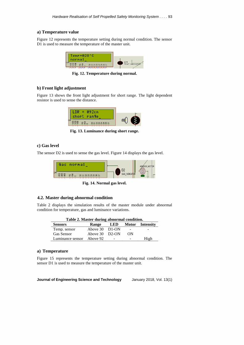
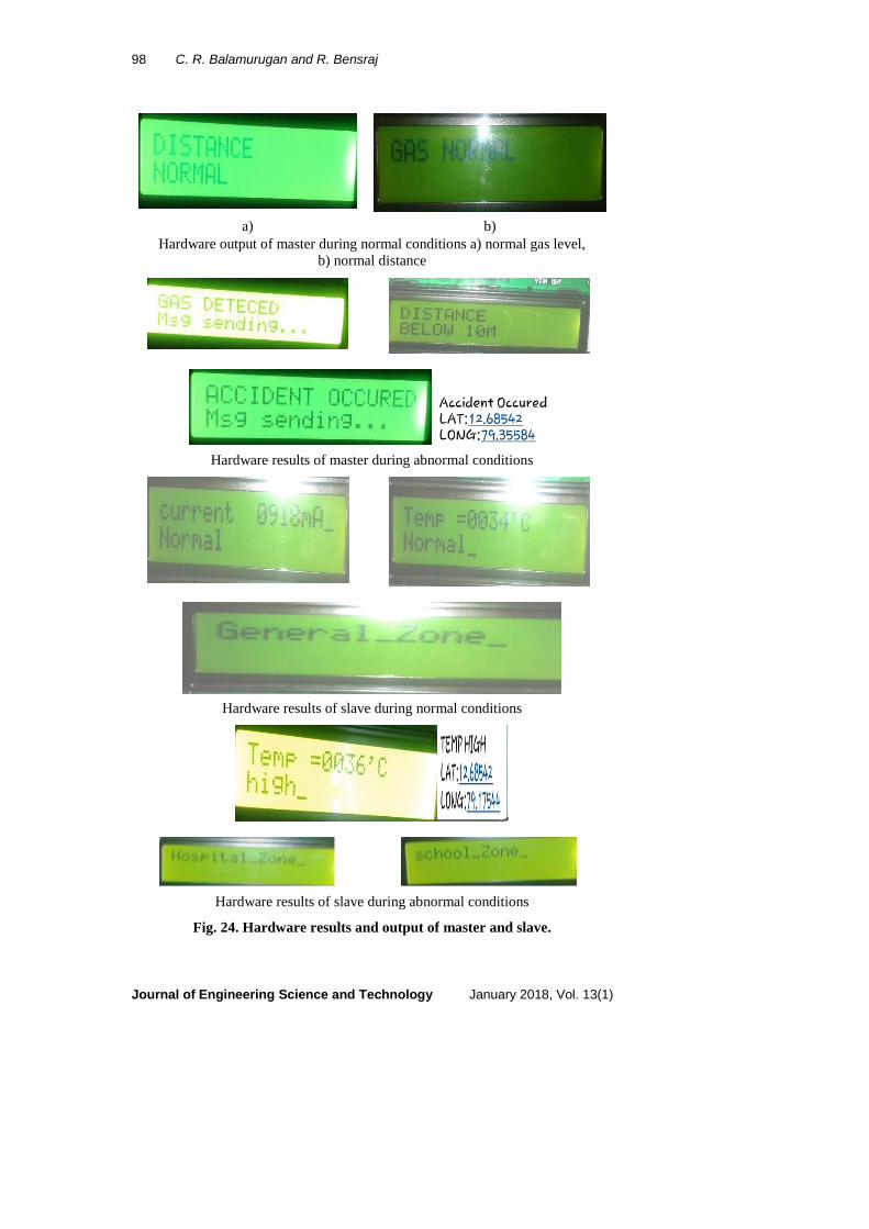
5. Hardware Results
In this hardware implementation, the sensors used in the simulation along with
other sensors are connected according to the block diagram along with the
accident alert system GPS and GSM and also with the IR sensor for distance
monitoring. The LCD and buzzer are used for indicating and displaying the sensor
value information. The GSM and GPS used to send alert message during the
emergency or accident period. It contains Master and Slave Modules; the sensors
are connected to each module separately. Figure 23 shows the hardware diagram
of the proposed work. The Master Module contains GSM, GPS for
communication, sensors like Gas sensor, IR sensor and Accident detection
switch are interfaced. In Slave module, Temperature sensor, RF transmitter
and receiver and current sensor are interfaced. Figure 24 displays the
hardware results and output of master and slave.

Hardware Realisation of Self Propelled Safety Monitoring System . . . . 97
Journal of Engineering Science and Technology January 2018, Vol. 13(1)
Fig. 23. Proposed hardware circuit.
The following parameters are used for the hardware implementation. Output
of each sensor is monitored through the LCD display. The sensors operate in two
ways during normal and abnormal conditions. Table 5 shows the comparison
between CAN and Ethernet. Similarly, Table 6 displays the comparison between
CAN, TTP and Flex ray.
Table 5. Comparison of CAN and Ethernet.
Sl. No CAN Ethernet
1 Secured communication No secured communication
2 Collision-free bus arbitration Suffer from bus arbitration collisions
3 Multi- and broadcasting are
reliable
Multi- and broadcasting are not
reliable
4 Data integrity is more Data integrity is less
Table 6. Comparison of CAN, TTP and Flex ray.
Sl. No CAN TTP Flex ray
1 Low complexity High complexity Very high complexity
2 Very less flexible
system
Less flexible
system Very flexible system
3 Ensure safety Moderate safety Motive safety
4 Lack of compos
ability
Robust level of
compos ability
High level of compos
ability
5 8 bytes Uses 2 frame Frame supports254
bytes
6 Bandwidth - 1mbps 2mbps 10 mbps
98 C. R. Balamurugan and R. Bensraj
Journal of Engineering Science and Technology January 2018, Vol. 13(1)
a) b)
Hardware output of master during normal conditions a) normal gas level,
b) normal distance
Hardware results of master during abnormal conditions
Hardware results of slave during normal conditions
Hardware results of slave during abnormal conditions
Fig. 24. Hardware results and output of master and slave.

Hardware Realisation of Self Propelled Safety Monitoring System . . . . 99
Journal of Engineering Science and Technology January 2018, Vol. 13(1)
6. Conclusions
This paper discusses about various safety measures that are needed in the
automotive vehicle. The safety measures include automatic brightness adjustment,
measuring engine area temperature, short circuit of electrical wirings, gas leakage
detection, automatic horn volume adjustment, distance maintenance, wheel
pressure monitoring, digital fuel indicating and accident alert system are provided
in this safety system. The sensors are connected to the Master and Slave modules
that are communicated through CAN protocol. The GSM and GPS are used to
send alert message to the rescue persons during emergency situations and the
simulation results and hardware implementation results are satisfactory to provide
a safety monitoring system and overcome the accidents. The comparison between
simulation and hardware results are shown in Table 7.
Table 7. Comparison of hardware and simulation results.
Sen
sors
Tem
pera
ture
sen
sor(L
M 3
5)
Cu
rren
t se
nso
r
Ga
s se
nso
r (
MQ
4)
IR s
en
sor
Lu
min
an
ce s
en
sor L
DR
RF
ID z
on
e E
M 1
8
Wh
eel
pre
ssu
re
TP
MS
Fu
el l
evel
sen
sor
Accid
en
t ale
rt
GP
S, G
SM
Sim
ula
tio
n R
esult
s
No
rmal
Con
dit
ion
Bel
ow
30 o
CD
1 O
FF
Bel
ow
0.3
2 A
mp
s
Bel
ow
30
D2
OF
F
-
Bel
ow
92
Ab
ov
e30
MG
ener
al
Ab
ov
eD5
OF
F
Ab
ov
e15
Ltr
sD3
OF
F
-
Ab
no
rmal
Cond
itio
n
Ab
ov
e30
o C
D1
ON
Ab
ov
e0.3
2 a
mp
s D
4
ON
Ab
ov
e30
D2 O
N
-
Ab
ov
e92
Bel
ow
30M
Ho
spit
al/S
choo
l
Bel
ow
D5 O
N
Bel
ow
15
Ltr
s D
3 O
N
-
Har
dw
are
Res
ult
s
No
rmal
con
dit
ion
Bel
ow
35
oC
Buzz
er O
FF
Ab
ov
e0.9
Am
ps
No
lea
kag
e
Ab
ov
e30
D6
OF
F
-
Ab
ov
e10
MG
ener
al
- - -
Ab
no
rmal
Cond
itio
n
Ab
ov
e35
o C
Bu
zzer
ON
Ale
rt S
MS
-
Lea
kag
e A
lert
SM
S
Bel
ow
30 D
6 O
N
-
Bel
ow
10M
Ho
spit
al/S
choo
l
- -
Acc
iden
t A
lert
SM
S

100 C. R. Balamurugan and R. Bensraj
Journal of Engineering Science and Technology January 2018, Vol. 13(1)
References
1. Kim, S.; Lee, E.; Choi, H.; and Seo, S. (2011). Design optimization of
vehicle control networks. IEEE Transactions on Vehicular Technology,
60(7), 3002-3016.
2. Yim, S. (2011). Design of a preview controller for vehicle rollover
prevention. IEEE Transactions on Vehicular Technology, 60(9), 4217-4226.
3. Hock, G.C.; Han, C.V.; Heong, O.K.; Md Din, N.; bin Ismail, A.; Jamaludin,
M.Z.; and Chakrabarty, C.K. (2011). Development of wireless controller area
network using low cost and low power consumption ARM microcontroller
for solar car application. IEEE International Conference on Control System,
Computing and Engineering, 244-248.
4. Jankovic, D.; Kleut, I.; and Blagojevic, V. (2011). Controller area network
based monitoring of vehicle’s mechatronics system. IEEE 9th International
Symposium on Intelligent Systems and Informatics, 269-274.
5. Guo, G.; and Yue, W. (2012) Autonomous platoon control allowing range-
limited sensors. IEEE Transactions on Vehicular Technology, 61(7), 2901-2912.
6. Ramya, V.; and Palaniappan, B. (2012). Embedded technology for vehicle
cabin safety monitoring and alerting system. International Journal of
Computer Science, Engineering and Applications (IJCSEA), 2(2), 83-94.
7. Higgins, M.D.; Green, R.J.; and Leeson, M.S. (2013). Optical wireless for
intravehicle communications: incorporating passenger presence scenarios.
IEEE Transactions. on Vehicular Technology, 62(8), 3510-3517.
8. Kwon, S.-C.; Stüber, G.L.; López; A.V.; and Papapolymerou, J. (2013).
Geometrically based statistical model for polarized body area network
channels. IEEE Trans. on Vehicular Technology, 62(8), 3518-3530.
9. Raibagi, A.S.; Anand, B.S.; and Swetha, R. (2013). Ultrasonic anti crashing
system for automobiles. International Journal of Advanced Research in
Computer and Communication Engineering, 2(4), 1774-1778.
10. Reddy, M.S.; Sreenivasulu, M.; Sudhakar; and Chakrapani. (2013) Advanced
SMART automobile safety information system. International Journal of
Engineering Trends and Technology, 4(7), 3154-3159.
11. Elbert, F.; Nüesch, T.; Ritter, A.; Murgovski, N.; and Guzzella, L. (2014).
Engine ON/OFF control for the energy management of a serial hybrid
electric bus via convex optimization. IEEE Transactions on Vehicular
Technology, 63(8), 3549-3559.
12. Joerer, S.; Segata, M.; Bloessl, B; Cigno, R.L.; Sommer, C.; and Dressler, F.
(2014). A vehicular networking perspective on estimating vehicle collision
probability at intersections. IEEE Transactions on Vehicular Technology,
63(4), 1802-1812.
13. Kachroo, P.; Shlayan, N.; Roy, S.; and Zhang, M. (2014). High-performance
vehicle streams: communication and control architecture. IEEE Transactions
on Vehicular Technology, 63(8), 3560-3568.
14. Song; H.-S.; Lu, S.-N.; Ma, X.; Yang, Y.; Liu, X.-Q.; and Zhang, P. (2014)
Vehicle behaviour analysis using target motion trajectories. IEEE
Transactions on Vehicular Technology, 63(8), 3580-3592.

Hardware Realisation of Self Propelled Safety Monitoring System . . . . 101
Journal of Engineering Science and Technology January 2018, Vol. 13(1)
15. Deng, B.; and Zhang, X. (2014). Car networking application in vehicle
safety. IEEE Workshop on Advanced Research and Technology in Industry
Applications, 834-837.
16. Kim, C.-S.; Hahn, J.-O.; Hong, K.-S.; and Yoo, W.-S. (2015) Estimation of
tire-road friction based on on-board 6-DoF acceleration measurement. IEEE
Transaction on Vehicular Technology, 64(8), 3368-3377.
17. Liu, K.; Lim, H.B.; Frazzoli, E.; Ji, H.; and Lee, V.C.S. (2015). Improving
positioning accuracy using GPS pseudorange measurements for cooperative
vehicular localization. IEEE Transactions on Vehicular Technology, 63(6),
2544-2556.
18. Belyaev; E.; Vinel, A.; Surak, A.; Gabbouj, M.; Jonsson, M.; and Egiazarian,
K. (2015). Robust vehicle-to-infrastructure video transmission for road
surveillance applications. IEEE Transactions on Vehicular Technology,
64(7), 2991-3003.
19. Shih, S.-E.; Tsai, W.-H. (2015). A convenient vision-based system for
automatic detection of parking spaces in indoor parking lots using wide-angle
cameras. IEEE Transactions on Vehicular Technology, 63(6), 2521-2532.
20. Căilean, A.-M.; and Dimian, M. (2016) Towards environmental-adaptive
visible light communications receivers for automotive applications: A
review. IEEE Sensors Journal, 16(9), 2903-3811.