Hardware co-simulations for image processing applications using MATLAB Simulink Xilinx Block-set «...
19
T hilina's Blog Hope this will work.. Hardware co-simulations for image processing applications using MATLAB Simulink Xilinx Block-set When working with image processing applications on hardware level, during the simulations I personally felt, very hard to work with bit/byte data, without seeing the resulting image/video data. For this kind of application we need to stream in and stream out data bits/bytes to and for the hardware module we implemented. MATLAB Simulink with combination of Xilinx Block-set gives great help in dealing this issue. By using MATLAB we can reshape images in to data stream as well as reshape data streams back in to images in MATLAB environment as I discussed in my previous article ( hp://thilinasameera.wordpress.com/2011/09/25/view-streamed-image-data-on-simulink-in-real-time/ ). But the problem rises with the complexity of the system in interest. According to the performance of your computer the simulation time can be varying, sometimes it may be able to take hours. Hardware Co simulations on MATLAB come as the solution for the pc performance limitation issue. In this article I am going to share my experiences on performing a hardware co-simulation on MATLAB with the FPGA development kit Atlys Spartan 6 with xls45-3 FPGA. Let’s take contract stretching technique ( hp://thilinasameera.wordpress.com/2011/03/23/contrast- stretching/ ) in image processing. In MATLAB; maer of fact just a few lines of codes. But when it goes to hardware level there are many important operations dealing on it. To perform this kind of an operation we need to keep concentrate on following factors. Data input is not a single matrix, but a stream of bits/bytes (in this case I use 8 bit parallel bus to transmit 1 byte per clock cycle Data input must perform when the system is ready to accept data You cannot input/ output floating point data into Xilinx block set. They must be either integer or fixed point Integer to double conversion, in this case we can use fixed to float conversion with acceptable precision Obtaining row and column Division Floating point multiplication resources vs. latency and clocking frequency Conversion back to fixed point (in this case to integer) All internal modules has to be synchronized A bout these ads ( hp://en.wordpress.com/about-these-ads/ ) Hardware co-simulations for image processing applications using MATL... http://thilinasameera.wordpress.com/2011/12/06/hardware-co-simulation... 1 of 19 2/4/2014 11:04 PM
-
Upload
vishal-nair -
Category
Documents
-
view
49 -
download
1
description
Brightness and Contrast in Matlab « Developers, Developers, Developers!
Transcript of Hardware co-simulations for image processing applications using MATLAB Simulink Xilinx Block-set «...
Thilina's Blog
Hope this will work..
Hardware co-simulations for image processing
applications using MATLAB Simulink Xilinx Block-set
When working with image processing applications on hardware level, during the simulations Ipersonally felt, very hard to work with bit/byte data, without seeing the resulting image/video data. Forthis kind of application we need to stream in and stream out data bits/bytes to and for the hardwaremodule we implemented. MATLAB Simulink with combination of Xilinx Block-set gives great help indealing this issue. By using MATLAB we can reshape images in to data stream as well as reshape datastreams back in to images in MATLAB environment as I discussed in my previous article(h(p://thilinasameera.wordpress.com/2011/09/25/view-streamed-image-data-on-simulink-in-real-time/).
But the problem rises with the complexity of the system in interest. According to the performance ofyour computer the simulation time can be varying, sometimes it may be able to take hours. HardwareCo simulations on MATLAB come as the solution for the pc performance limitation issue. In this articleI am going to share my experiences on performing a hardware co-simulation on MATLAB with theFPGA development kit Atlys Spartan 6 with xls45-3 FPGA.
Let’s take contract stretching technique (h(p://thilinasameera.wordpress.com/2011/03/23/contrast-stretching/) in image processing. In MATLAB; ma(er of fact just a few lines of codes. But when it goesto hardware level there are many important operations dealing on it. To perform this kind of anoperation we need to keep concentrate on following factors.
Data input is not a single matrix, but a stream of bits/bytes (in this case I use 8 bit parallel bus totransmit 1 byte per clock cycleData input must perform when the system is ready to accept dataYou cannot input/ output floating point data into Xilinx block set. They must be either integer orfixed pointInteger to double conversion, in this case we can use fixed to float conversion with acceptableprecisionObtaining row and columnDivisionFloating point multiplication resources vs. latency and clocking frequencyConversion back to fixed point (in this case to integer)All internal modules has to be synchronized
About these ads (h(p://en.wordpress.com/about-these-ads/)
Hardware co-simulations for image processing applications using MATL... http://thilinasameera.wordpress.com/2011/12/06/hardware-co-simulation...
1 of 19 2/4/2014 11:04 PM
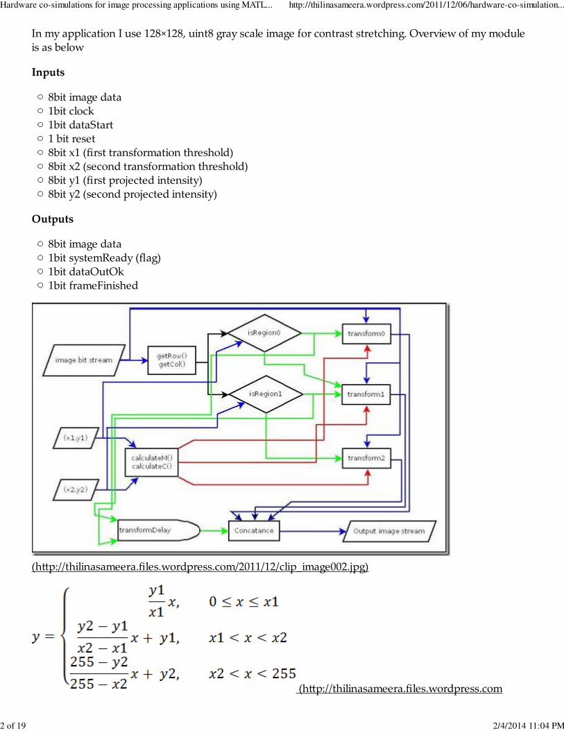
In my application I use 128×128, uint8 gray scale image for contrast stretching. Overview of my moduleis as below
Inputs
8bit image data1bit clock1bit dataStart1 bit reset8bit x1 (first transformation threshold)8bit x2 (second transformation threshold)8bit y1 (first projected intensity)8bit y2 (second projected intensity)
Outputs
8bit image data1bit systemReady (flag)1bit dataOutOk1bit frameFinished
(h(p://thilinasameera.files.wordpress.com/2011/12/clip_image002.jpg)
(h(p://thilinasameera.files.wordpress.com
Hardware co-simulations for image processing applications using MATL... http://thilinasameera.wordpress.com/2011/12/06/hardware-co-simulation...
2 of 19 2/4/2014 11:04 PM
/2011/12/clip_image003.gif)
Even-though the block diagram shows 3 transformation blocks it can be optimized for one operationblock. Since the m,c values also needed to calculate one time per operation by sacrificing few clockcycles, we can further optimize the usage of hardware resources by converting system to a simple statemachine.
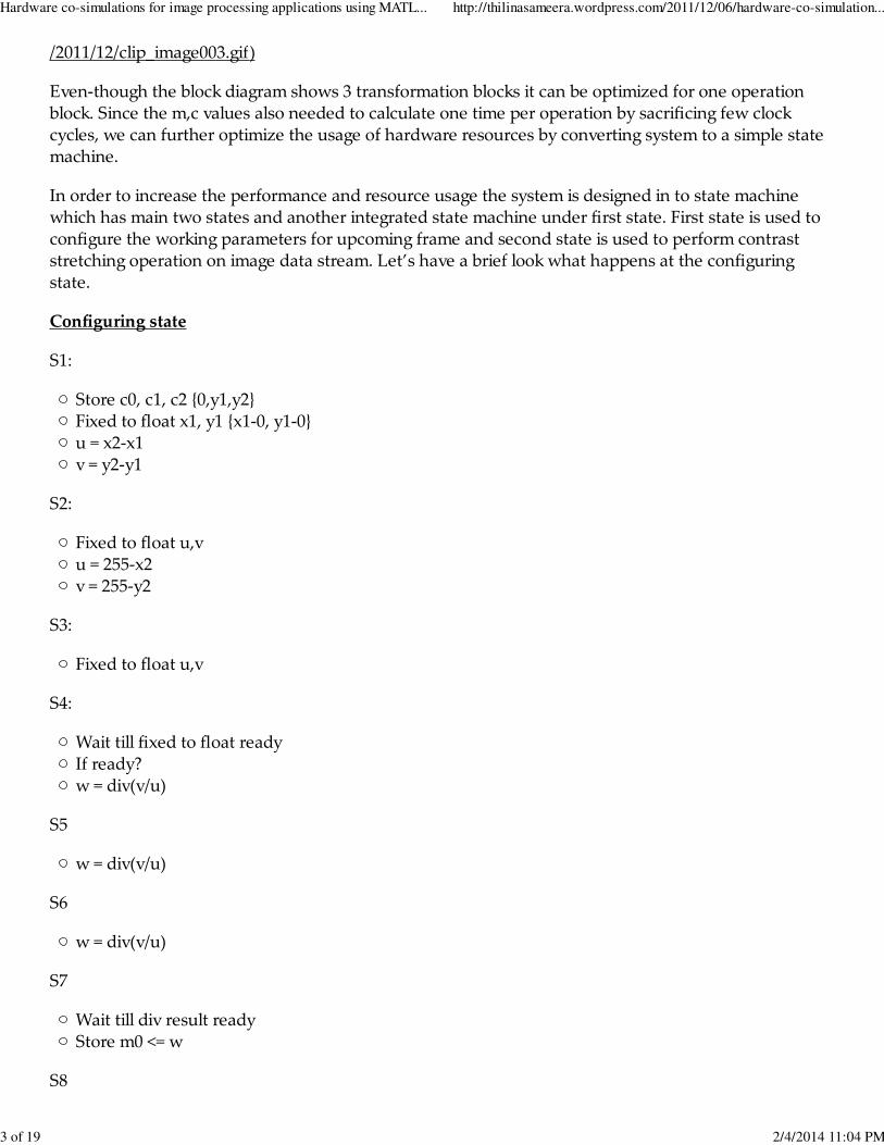
In order to increase the performance and resource usage the system is designed in to state machinewhich has main two states and another integrated state machine under first state. First state is used toconfigure the working parameters for upcoming frame and second state is used to perform contraststretching operation on image data stream. Let’s have a brief look what happens at the configuringstate.
Configuring state
S1:
Store c0, c1, c2 {0,y1,y2}Fixed to float x1, y1 {x1-0, y1-0}u = x2-x1v = y2-y1
S2:
Fixed to float u,vu = 255-x2v = 255-y2
S3:
Fixed to float u,v
S4:
Wait till fixed to float readyIf ready?w = div(v/u)
S5
w = div(v/u)
S6
w = div(v/u)
S7
Wait till div result readyStore m0 <= w
S8
Hardware co-simulations for image processing applications using MATL... http://thilinasameera.wordpress.com/2011/12/06/hardware-co-simulation...
3 of 19 2/4/2014 11:04 PM

Store m1 <=w
S9
Store m2 <=wGo to Main State 2 (processing mode)
With the operation performed in state 1 the coefficients for three transforming functions y = mx + c,now all m values are stored as floating point numbers as well as the c values are stored as integers. Theprocessing state is a pipelined system. In this system there is are two delay blocks, one for pipeline m tillthe x value converted to float and the c till x to float, multiplied by m and back converted to fix as below
One always block will check value to decide the region of x and sent it to float conversion, at the sametime using the flag corresponding m and c values will be send to delayed pipe line to use in properstates. Then the multiplication starts at the end of floating point conversion. At the end of this pipelineit will be re-converted to fixed and add the mapped C value and streamed out from the core.
You can use Xilinx Core generator to generate modules which required using in floating pointarithmetic and delay elements. Modules and its source cores are as below,
Module Core source Configuration
Fixed to float flfloating point under math operations fifixed to float
Float to fixed flfloating point under math operations flfloat to fixed
Float multiplication flfloating point under math operations multiplication
Float division flfloating point under math operations division
Delay RAM based shift register none
Special codes on the algorithm are as below.
Co-efficient generation part
Hardware co-simulations for image processing applications using MATL... http://thilinasameera.wordpress.com/2011/12/06/hardware-co-simulation...
4 of 19 2/4/2014 11:04 PM
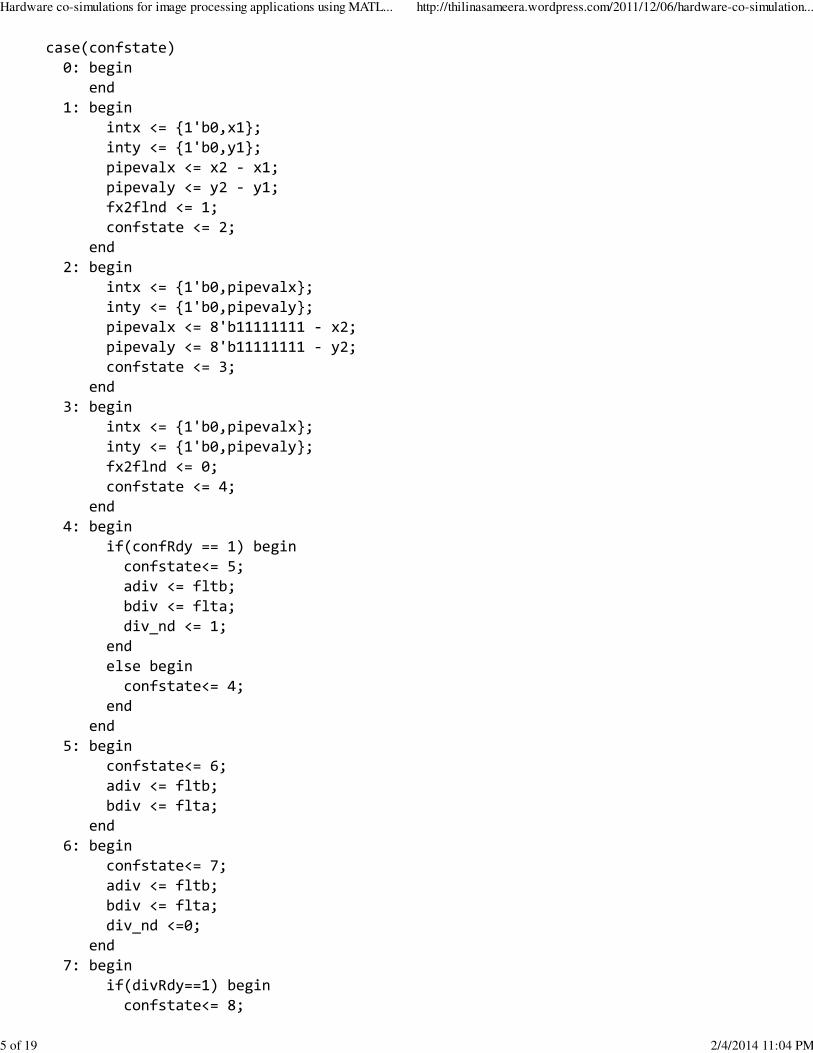
case(confstate) 0: begin end 1: begin intx <= {1'b0,x1}; inty <= {1'b0,y1}; pipevalx <= x2 - x1; pipevaly <= y2 - y1; fx2flnd <= 1; confstate <= 2; end 2: begin intx <= {1'b0,pipevalx}; inty <= {1'b0,pipevaly}; pipevalx <= 8'b11111111 - x2; pipevaly <= 8'b11111111 - y2; confstate <= 3; end 3: begin intx <= {1'b0,pipevalx}; inty <= {1'b0,pipevaly}; fx2flnd <= 0; confstate <= 4; end 4: begin if(confRdy == 1) begin confstate<= 5; adiv <= fltb; bdiv <= flta; div_nd <= 1; end else begin confstate<= 4; end end 5: begin confstate<= 6; adiv <= fltb; bdiv <= flta; end 6: begin confstate<= 7; adiv <= fltb; bdiv <= flta; div_nd <=0; end 7: begin if(divRdy==1) begin confstate<= 8;
Hardware co-simulations for image processing applications using MATL... http://thilinasameera.wordpress.com/2011/12/06/hardware-co-simulation...
5 of 19 2/4/2014 11:04 PM

m0 <= divRes; end else begin confstate<= 7; end end 8: begin confstate<= 9; m1 <= divRes; end 9: begin confstate<= 10; m2 <= divRes; ready <= 1; end 10:begin if(stream==1) begin state <= 1; end else begin confstate<=10; end endendcase
Data processing part
case(region) 0: begin md <= m0; cd <= 9'b0; intx <= streamdata; fx2flnd <= 1; end 1: begin md <= m1; cd <= {1'b0,y1}; intx <= streamdata; fx2flnd <= 1; end 2: begin md <= m2; cd <= {1'b0,y2}; intx <= streamdata; fx2flnd <= 1; endendcase
Region defining part
Hardware co-simulations for image processing applications using MATL... http://thilinasameera.wordpress.com/2011/12/06/hardware-co-simulation...
6 of 19 2/4/2014 11:04 PM

always @(negedge clk) begin if( imagedata<x1) begin streamdata <= {1'b0,imagedata}; region <= 0; end else if (imagedata<x2) begin streamdata <= {1'b0,imagedata - x1}; region <= 1; end else begin streamdata <= {1'b0,imagedata - x2}; region <= 2; endend
When considering hardware co-simulation on MATLAB we need to follow additional coding practicesto generate the co-simulation model. Additional coding methods are as below.
1. Only put the I/O variable name in module initiation area and define its sizes in the body of program.
2. Do not set initial values with the declaration of variables; initialize them separately within initial block.
3. Do not use capital le(ers in either I/O ports or interacting module names or in module name. This willcause MATLAB to give you an error when you initiate a black box.
4. Use the core initiation template to initialize your modules to main module.
5. Make sure to run MATLAB as “Run as Administrator” or else nothing will be happen.
core_name instant_name( .port_name_of_core(port_name_in_module), //..............(other ports));
Forma(ed code will be as below.
Hardware co-simulations for image processing applications using MATL... http://thilinasameera.wordpress.com/2011/12/06/hardware-co-simulation...
7 of 19 2/4/2014 11:04 PM
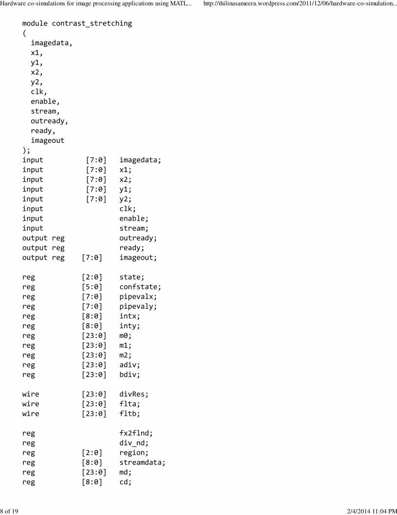
module contrast_stretching( imagedata, x1, y1, x2, y2, clk, enable, stream, outready, ready, imageout);input [7:0] imagedata;input [7:0] x1;input [7:0] x2;input [7:0] y1;input [7:0] y2;input clk;input enable;input stream;output reg outready;output reg ready;output reg [7:0] imageout;
reg [2:0] state;reg [5:0] confstate;reg [7:0] pipevalx;reg [7:0] pipevaly;reg [8:0] intx;reg [8:0] inty;reg [23:0] m0;reg [23:0] m1;reg [23:0] m2;reg [23:0] adiv;reg [23:0] bdiv;
wire [23:0] divRes;wire [23:0] flta;wire [23:0] fltb;
reg fx2flnd;reg div_nd;reg [2:0] region;reg [8:0] streamdata;reg [23:0] md;reg [8:0] cd;
Hardware co-simulations for image processing applications using MATL... http://thilinasameera.wordpress.com/2011/12/06/hardware-co-simulation...
8 of 19 2/4/2014 11:04 PM
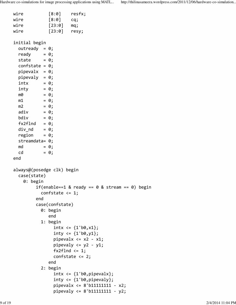
wire [8:0] resfx;wire [8:0] cq;wire [23:0] mq;wire [23:0] resy;
initial begin outready = 0; ready = 0; state = 0; confstate = 0; pipevalx = 0; pipevaly = 0; intx = 0; inty = 0; m0 = 0; m1 = 0; m2 = 0; adiv = 0; bdiv = 0; fx2flnd = 0; div_nd = 0; region = 0; streamdata= 0; md = 0; cd = 0;end
always@(posedge clk) begin case(state) 0: begin if(enable==1 & ready == 0 & stream == 0) begin confstate <= 1; end case(confstate) 0: begin end 1: begin intx <= {1'b0,x1}; inty <= {1'b0,y1}; pipevalx <= x2 - x1; pipevaly <= y2 - y1; fx2flnd <= 1; confstate <= 2; end 2: begin intx <= {1'b0,pipevalx}; inty <= {1'b0,pipevaly}; pipevalx <= 8'b11111111 - x2; pipevaly <= 8'b11111111 - y2;
Hardware co-simulations for image processing applications using MATL... http://thilinasameera.wordpress.com/2011/12/06/hardware-co-simulation...
9 of 19 2/4/2014 11:04 PM
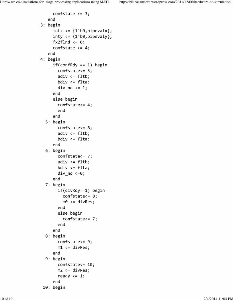
confstate <= 3; end 3: begin intx <= {1'b0,pipevalx}; inty <= {1'b0,pipevaly}; fx2flnd <= 0; confstate <= 4; end 4: begin if(confRdy == 1) begin confstate<= 5; adiv <= fltb; bdiv <= flta; div_nd <= 1; end else begin confstate<= 4; end end 5: begin confstate<= 6; adiv <= fltb; bdiv <= flta; end 6: begin confstate<= 7; adiv <= fltb; bdiv <= flta; div_nd <=0; end 7: begin if(divRdy==1) begin confstate<= 8; m0 <= divRes; end else begin confstate<= 7; end end 8: begin confstate<= 9; m1 <= divRes; end 9: begin confstate<= 10; m2 <= divRes; ready <= 1; end 10: begin
Hardware co-simulations for image processing applications using MATL... http://thilinasameera.wordpress.com/2011/12/06/hardware-co-simulation...
10 of 19 2/4/2014 11:04 PM
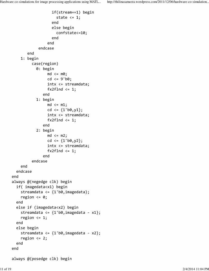
if(stream==1) begin state <= 1; end else begin confstate<=10; end end endcase end 1: begin case(region) 0: begin md <= m0; cd <= 9'b0; intx <= streamdata; fx2flnd <= 1; end 1: begin md <= m1; cd <= {1'b0,y1}; intx <= streamdata; fx2flnd <= 1; end 2: begin md <= m2; cd <= {1'b0,y2}; intx <= streamdata; fx2flnd <= 1; end endcase end endcaseendalways @(negedge clk) begin if( imagedata<x1) begin streamdata <= {1'b0,imagedata}; region <= 0; end else if (imagedata<x2) begin streamdata <= {1'b0,imagedata - x1}; region <= 1; end else begin streamdata <= {1'b0,imagedata - x2}; region <= 2; endend
always @(posedge clk) begin
Hardware co-simulations for image processing applications using MATL... http://thilinasameera.wordpress.com/2011/12/06/hardware-co-simulation...
11 of 19 2/4/2014 11:04 PM
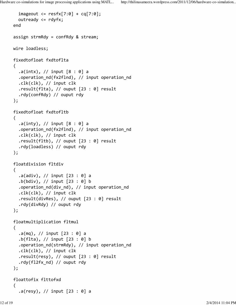
imageout <= resfx[7:0] + cq[7:0]; outready <= rdyfx;end
assign strmRdy = confRdy & stream;
wire loadless;
fixedtofloat fxdtoflta( .a(intx), // input [8 : 0] a .operation_nd(fx2flnd), // input operation_nd .clk(clk), // input clk .result(flta), // ouput [23 : 0] result .rdy(confRdy) // ouput rdy);
fixedtofloat fxdtofltb( .a(inty), // input [8 : 0] a .operation_nd(fx2flnd), // input operation_nd .clk(clk), // input clk .result(fltb), // ouput [23 : 0] result .rdy(loadless) // ouput rdy);
floatdivision fltdiv( .a(adiv), // input [23 : 0] a .b(bdiv), // input [23 : 0] b .operation_nd(div_nd), // input operation_nd .clk(clk), // input clk .result(divRes), // ouput [23 : 0] result .rdy(divRdy) // ouput rdy);
floatmultiplication fltmul( .a(mq), // input [23 : 0] a .b(flta), // input [23 : 0] b .operation_nd(strmRdy), // input operation_nd .clk(clk), // input clk .result(resy), // ouput [23 : 0] result .rdy(fl2fx_nd) // ouput rdy);
floattofix flttofxd( .a(resy), // input [23 : 0] a
Hardware co-simulations for image processing applications using MATL... http://thilinasameera.wordpress.com/2011/12/06/hardware-co-simulation...
12 of 19 2/4/2014 11:04 PM

.operation_nd(fl2fx_nd), // input operation_nd .clk(clk), // input clk .result(resfx), // ouput [8 : 0] result .rdy(rdyfx) // ouput rdy);
mtunnel mdelay( .d(md), // input [23 : 0] d .clk(clk), // input clk .q(mq) // output [23 : 0] q);
ctunnel cdelay( .d(cd), // input [8 : 0] d .clk(clk), // input clk .q(cq) // output [8 : 0] q);
endmodule
Simulation model will be as follows,
Hardware co-simulations for image processing applications using MATL... http://thilinasameera.wordpress.com/2011/12/06/hardware-co-simulation...
13 of 19 2/4/2014 11:04 PM
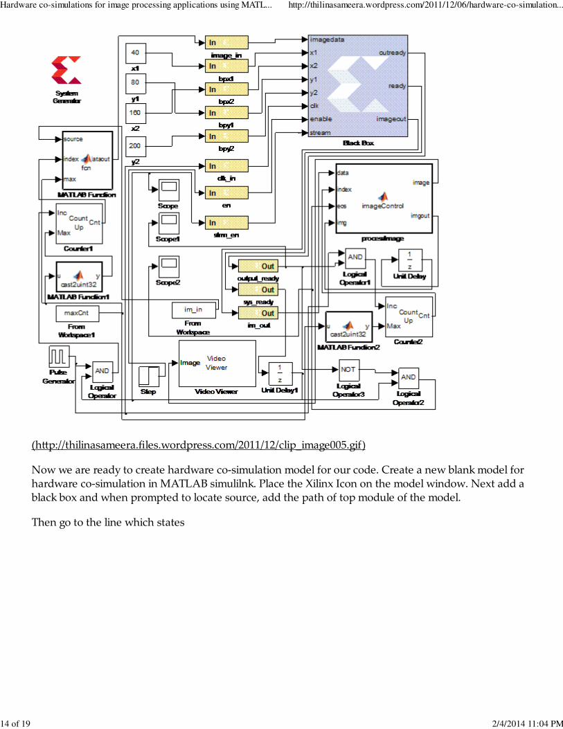
(h(p://thilinasameera.files.wordpress.com/2011/12/clip_image005.gif)
Now we are ready to create hardware co-simulation model for our code. Create a new blank model forhardware co-simulation in MATLAB simulilnk. Place the Xilinx Icon on the model window. Next add ablack box and when prompted to locate source, add the path of top module of the model.
Then go to the line which states
Hardware co-simulations for image processing applications using MATL... http://thilinasameera.wordpress.com/2011/12/06/hardware-co-simulation...
14 of 19 2/4/2014 11:04 PM
% Add addtional source files as needed.
% |-------------% | Add files in the order in which they should be compiled.% | If two files "a.vhd" and "b.vhd" contain the entities% | entity_a and entity_b, and entity_a contains a% | component of type entity_b, the correct sequence of% | addFile() calls would be:% | this_block.addFile('b.vhd');% | this_block.addFile('a.vhd');% |-------------% this_block.addFile('');% this_block.addFile('');
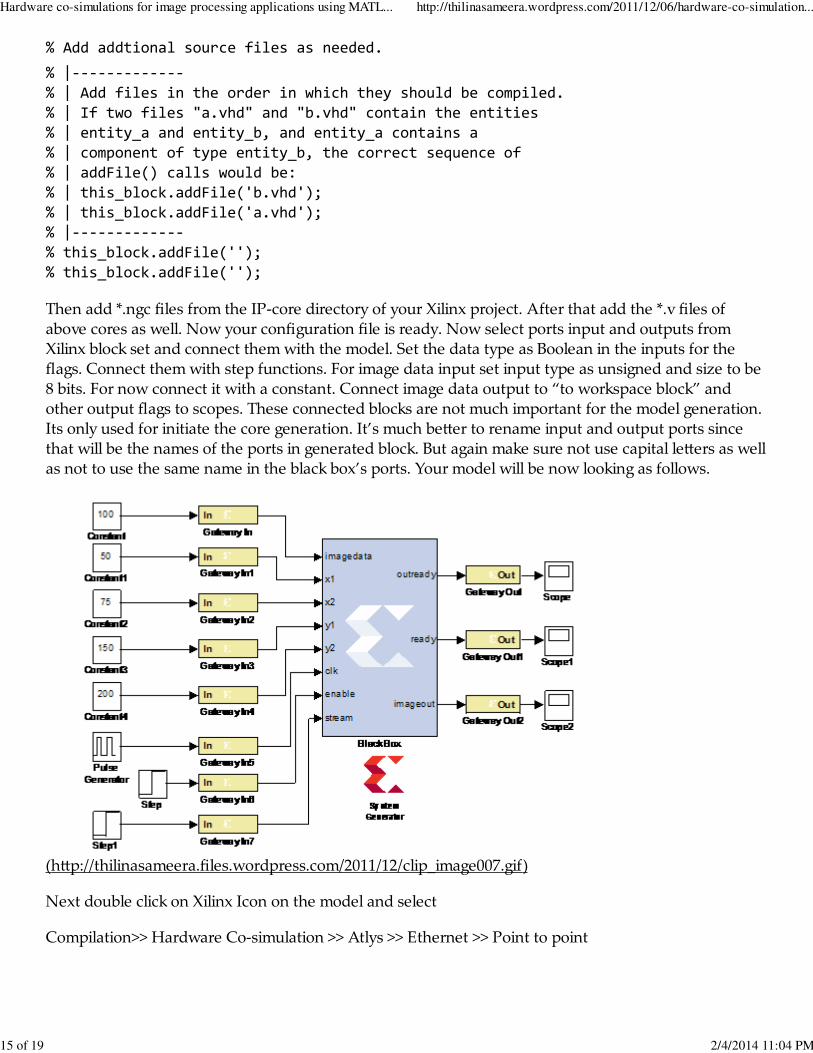
Then add *.ngc files from the IP-core directory of your Xilinx project. After that add the *.v files ofabove cores as well. Now your configuration file is ready. Now select ports input and outputs fromXilinx block set and connect them with the model. Set the data type as Boolean in the inputs for theflags. Connect them with step functions. For image data input set input type as unsigned and size to be8 bits. For now connect it with a constant. Connect image data output to “to workspace block” andother output flags to scopes. These connected blocks are not much important for the model generation.Its only used for initiate the core generation. It’s much be(er to rename input and output ports sincethat will be the names of the ports in generated block. But again make sure not use capital le(ers as wellas not to use the same name in the black box’s ports. Your model will be now looking as follows.
(h(p://thilinasameera.files.wordpress.com/2011/12/clip_image007.gif)
Next double click on Xilinx Icon on the model and select
Compilation>> Hardware Co-simulation >> Atlys >> Ethernet >> Point to point
Hardware co-simulations for image processing applications using MATL... http://thilinasameera.wordpress.com/2011/12/06/hardware-co-simulation...
15 of 19 2/4/2014 11:04 PM
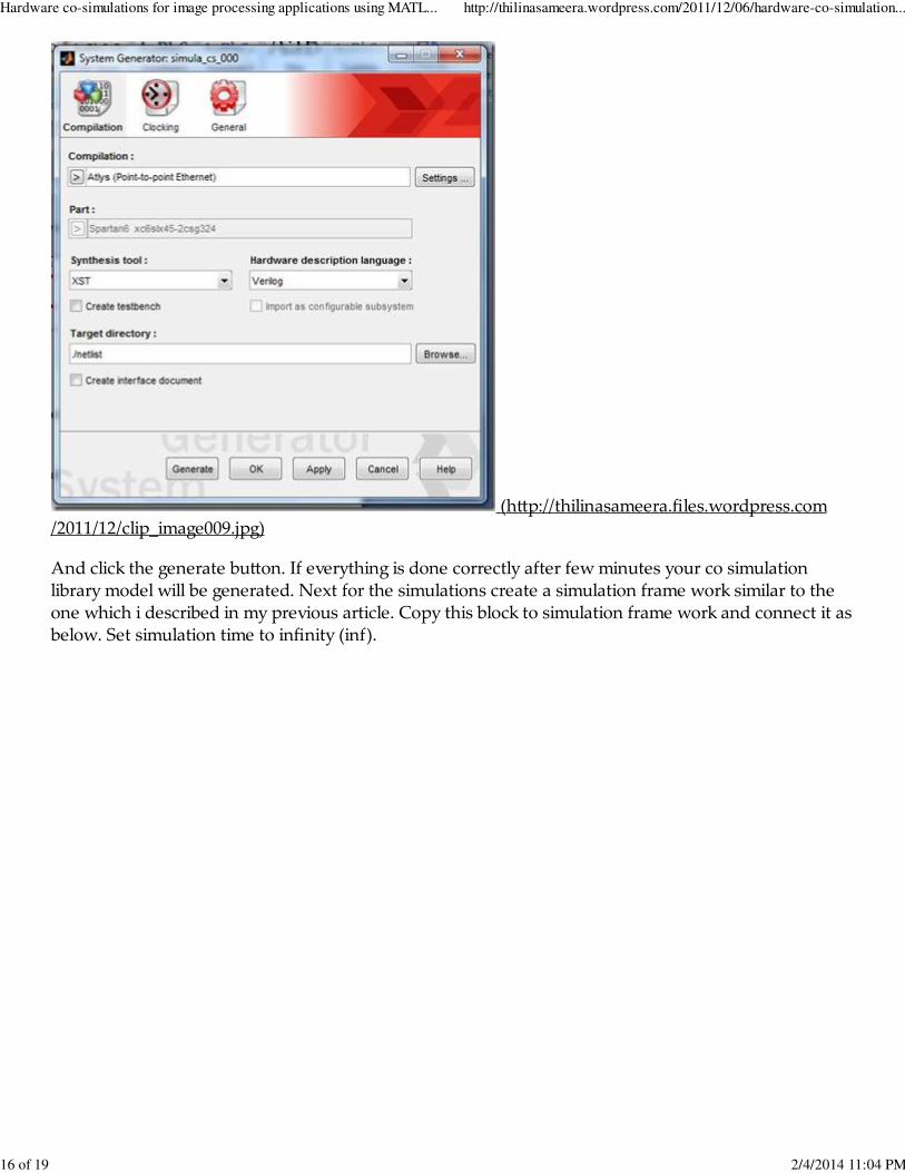
(h(p://thilinasameera.files.wordpress.com/2011/12/clip_image009.jpg)
And click the generate bu(on. If everything is done correctly after few minutes your co simulationlibrary model will be generated. Next for the simulations create a simulation frame work similar to theone which i described in my previous article. Copy this block to simulation frame work and connect it asbelow. Set simulation time to infinity (inf).
Hardware co-simulations for image processing applications using MATL... http://thilinasameera.wordpress.com/2011/12/06/hardware-co-simulation...
16 of 19 2/4/2014 11:04 PM
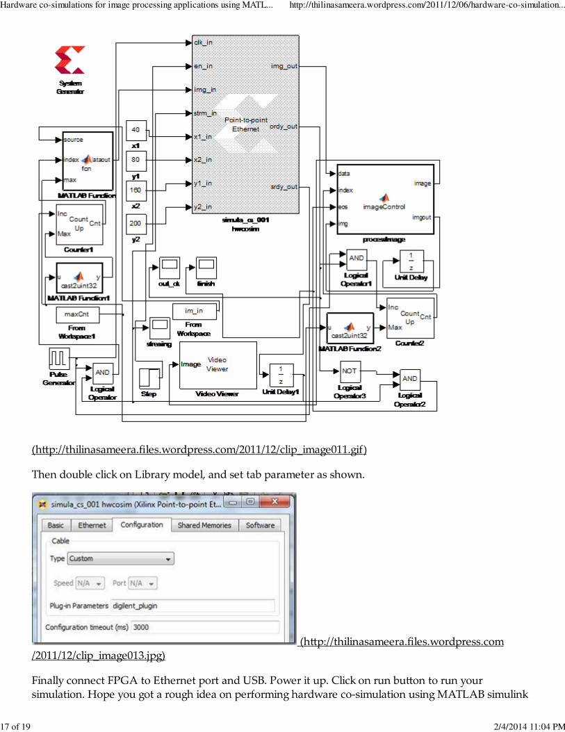
(h(p://thilinasameera.files.wordpress.com/2011/12/clip_image011.gif)
Then double click on Library model, and set tab parameter as shown.
(h(p://thilinasameera.files.wordpress.com/2011/12/clip_image013.jpg)
Finally connect FPGA to Ethernet port and USB. Power it up. Click on run bu(on to run yoursimulation. Hope you got a rough idea on performing hardware co-simulation using MATLAB simulink
Hardware co-simulations for image processing applications using MATL... http://thilinasameera.wordpress.com/2011/12/06/hardware-co-simulation...
17 of 19 2/4/2014 11:04 PM

for Xilinx FPGA devices. Thank you very much for reading.
2011 December 6 - Posted by Thilina S. | Electronics, FPGA, Image Processing, MATLAB, Technology
1 Comment »
Hello sirits, a really good article for simulink and xilinx block co-simulation. I also tried read an image,process it and display it. But when I read the image, searilize it again deserilize it and send to videoviewer it works ok (this is only for demo purpose). But when I connect the Gateway In, Black Boxand Gateway Out, I get only black image. Can you address me about the problem? If you give meyour email address, I can send the model also to you. Expecting your reply.
RegardsRavi
Comment by Ravindra Patil | 2011 December 29 | Reply
1.
About
I am Thilina Sameera from Sri Lanka. I completed my undergraduate studies on Electronic andTelecommunication Engineering in University of Moratuwa and currently doing my post graduatestudies on Computer Vision and Processor Design at the Department of Electronic andTelecommunication Engineering, University of Moratuwa. I am working as a Biomedical ResearchEngineer at “Premium International – University of Moratuwa, Research and Development Laboratoryfor Biomedical Technologies” at the Department of Electronic and Telecommunication Engineering,University of Moratuwa.
Site info
Thilinaʹs BlogThe Andreas04 Theme.
Follow
Hardware co-simulations for image processing applications using MATL... http://thilinasameera.wordpress.com/2011/12/06/hardware-co-simulation...
18 of 19 2/4/2014 11:04 PM

Follow “Thilina's Blog”
Powered by WordPress.com
Hardware co-simulations for image processing applications using MATL... http://thilinasameera.wordpress.com/2011/12/06/hardware-co-simulation...
19 of 19 2/4/2014 11:04 PM