Hardware and System Software Specification (Bill of ... CRM Connector for Salesforce.com, PeopleSoft...
71
Hardware and System Software Specification (Bill of Materials) for Cisco Unified ICM/Contact Center Enterprise & Hosted Release 9.0(x) Revision 1.21 Last Updated: October 26, 2015 Corporate Headquarters Cisco Systems, Inc. 170 West Tasman Drive San Jose, CA 95134-1706 USA http://www.cisco.comTel: 408 526-4000 800 553-NETS (6387) Fax: 408 526-4100
Transcript of Hardware and System Software Specification (Bill of ... CRM Connector for Salesforce.com, PeopleSoft...
Hardware and System Software Specification (Bill of Materials) for Cisco Unified ICM/Contact Center Enterprise & Hosted
Release 9.0(x)
Revision 1.21
Last Updated: October 26, 2015
Corporate Headquarters
Cisco Systems, Inc. 170 West Tasman Drive San Jose, CA 95134-1706 USA Uhttp://www.cisco.comU Tel: 408 526-4000 800 553-NETS (6387) Fax: 408 526-4100
Cisco Unified ICM/Contact Center Enterprise & Hosted Editions, Release 9.0(x)
Hardware and System Software Specification
© 2008 – 2014 Cisco Systems, Inc. i
THE SPECIFICATIONS AND INFORMATION REGARDING THE PRODUCTS IN THIS MANUAL
ARE SUBJECT TO CHANGE WITHOUT NOTICE. ALL STATEMENTS, INFORMATION, AND
RECOMMENDATIONS IN THIS MANUAL ARE BELIEVED TO BE ACCURATE BUT ARE
PRESENTED WITHOUT WARRANTY OF ANY KIND, EXPRESS OR IMPLIED. USERS MUST
TAKE FULL RESPONSIBILITY FOR THEIR APPLICATION OF ANY PRODUCTS.
THE SOFTWARE LICENSE AND LIMITED WARRANTY FOR THE ACCOMPANYING PRODUCT
ARE SET FORTH IN THE INFORMATION PACKET THAT SHIPPED WITH THE PRODUCT AND
ARE INCORPORATED HEREIN BY THIS REFERENCE. IF YOU ARE UNABLE TO LOCATE THE
SOFTWARE LICENSE OR LIMITED WARRANTY, CONTACT YOUR CISCO REPRESENTATIVE
FOR A COPY.
The Cisco implementation of TCP header compression is an adaptation of a program developed by the
University of California, Berkeley (UCB) as part of UCBs public domain version of the UNIX operating
system. All rights reserved. Copyright 1981, Regents of the University of California.
NOTWITHSTANDING ANY OTHER WARRANTY HEREIN, ALL DOCUMENT FILES AND
SOFTWARE OF THESE SUPPLIERS ARE PROVIDED "AS IS" WITH ALL FAULTS. CISCO AND
THE ABOVE-NAMED SUPPLIERS DISCLAIM ALL WARRANTIES, EXPRESSED OR IMPLIED,
INCLUDING, WITHOUT LIMITATION, THOSE OF MERCHANTABILITY, FITNESS FOR A
PARTICULAR PURPOSE AND NONINFRINGEMENT OR ARISING FROM A COURSE OF
DEALING, USAGE, OR TRADE PRACTICE.
IN NO EVENT SHALL CISCO OR ITS SUPPLIERS BE LIABLE FOR ANY INDIRECT, SPECIAL,
CONSEQUENTIAL, OR INCIDENTAL DAMAGES, INCLUDING, WITHOUT LIMITATION, LOST
PROFITS OR LOSS OR DAMAGE TO DATA ARISING OUT OF THE USE OR INABILITY TO USE
THIS MANUAL, EVEN IF CISCO OR ITS SUPPLIERS HAVE BEEN ADVISED OF THE
POSSIBILITY OF SUCH DAMAGES.
Cisco and the Cisco logo are trademarks or registered trademarks of Cisco and/or its affiliates in the U.S.
and other countries. To view a list of Cisco trademarks, go to Uhttp://www.cisco.com/go/trademarksU
CCVP, the Cisco logo, and Welcome to the Human Network are trademarks of Cisco Systems, Inc.;
Changing the Way We Work, Live, Play, and Learn is a service mark of Cisco Systems, Inc.; and Access
Registrar, Aironet, Catalyst, CCDA, CCDP, CCIE, CCIP, CCNA, CCNP, CCSP, Cisco, the Cisco Certified
Internetwork Expert logo, Cisco IOS, Cisco Press, Cisco Systems, Cisco Systems Capital, the Cisco
Systems logo, Cisco Unity, Enterprise/Solver, EtherChannel, EtherFast, EtherSwitch, Fast Step, Follow Me
Browsing, FormShare, GigaDrive, HomeLink, Internet Quotient, IOS, iPhone, IP/TV, iQ Expertise, the iQ
logo, iQ Net Readiness Scorecard, iQuick Study, LightStream, Linksys, MeetingPlace, MGX, Networkers,
Networking Academy, Network Registrar, PIX, ProConnect, ScriptShare, SMARTnet, StackWise, The
Fastest Way to Increase Your Internet Quotient, and TransPath are registered trademarks of Cisco Systems,
Inc. and/or its affiliates in the United States and certain other countries. Any Internet Protocol (IP)
addresses used in this document are not intended to be actual addresses. Any examples, command display
output, and figures included in the document are shown for illustrative purposes only. Any use of actual IP
addresses in illustrative content is unintentional and coincidental.
Third-party trademarks mentioned are the property of their respective owners. The use of the word partner
does not imply a partnership relationship between Cisco and any other company. (1110R)
Copyright 2008–2014 Cisco Systems, Inc. All rights reserved.
Cisco Unified ICM/Contact Center Enterprise & Hosted Editions, Release 9.0(x)
Hardware and System Software Specification
© 2008 – 2014 Cisco Systems, Inc. ii
Table of Contents
1 OVERVIEW ........................................................................................................................................ 1
1.1 HARDWARE, SYSTEM SOFTWARE*, AND CAPACITY SIZING .............................................................. 1 1.2 UPDATED INFORMATION IN THIS DOCUMENT ................................................................................... 2
2 REFERENCES .................................................................................................................................... 3
3 SERVERS FOR CISCO CONTACT CENTER PRODUCTS ........................................................ 4
3.1 SERVER HARDWARE CONFIGURATION GUIDELINES.......................................................................... 5
4 SUPPORTED REDUNDANT HARDWARE ................................................................................... 5
4.1.1 CPU ........................................................................................................................................ 5 4.1.2 NIC Speed/Duplex Configuration ........................................................................................... 5 4.1.3 Storage Hardware .................................................................................................................. 6 4.1.4 Configuration Guidelines ....................................................................................................... 6
4.1.4.1 Supported Configurations .................................................................................................................. 7 4.1.4.2 4BUnsupported Configurations ......................................................................................................... 7
4.1.5 Alternative Storage Option ..................................................................................................... 7 4.1.6 Unqualified Backup Options ................................................................................................... 8
5 SOFTWARE UPGRADE AND INSTALLATION CONSIDERATIONS ..................................... 9
6 SOFTWARE SCALABILITY, CONSTRAINTS, AND OPERATING CONDITIONS .............10
6.1 UNIFIED ICM/CCE CONFIGURATION LIMITS AND SCALABILITY CONSTRAINTS ..............................10 6.1.1 Deployment-specific limits for AW and HDS Servers per Logger Side .................................15
6.2 UNIFIED ICM/UNIFIED CCE OPERATING CONDITIONS ....................................................................15 6.3 CONGESTION CONTROL ...................................................................................................................16 6.4 UNIFIED ICM/UNIFIED CCE SCALABILITY ......................................................................................17
6.4.1 CTI OS Security Scalability ...................................................................................................17 6.4.2 Mobile Agents Scalability ......................................................................................................17 6.4.3 Outbound Option Scalability .................................................................................................17 6.4.4 Agent Greeting Scalability .....................................................................................................18
7 SERVER HARDWARE REQUIREMENTS...................................................................................19
7.1 CISCO UNIFIED CONTACT CENTER ENTERPRISE ..............................................................................19 7.1.1 Agent PG Configuration Options ..........................................................................................19 7.1.2 New Deployments and Technology Refresh ...........................................................................20
7.1.2.1 Option 1: Supports up to 450 Agents .............................................................................................. 20 7.1.2.2 Option 2: Supports up to 4000 Agents ............................................................................................ 21 7.1.2.3 Option 3: Supports up to 8000 Agents ............................................................................................ 21 7.1.2.4 Option 4: Supports up to 12,000 Agents ......................................................................................... 22
7.1.3 Common Ground Upgrade ....................................................................................................22 7.1.3.1 Option 1: Supports up to 450 Agents .............................................................................................. 22 7.1.3.2 Option 2: Supports up to 1275 Agents ............................................................................................ 23 7.1.3.3 Option 3: Supports up to 5100 Agents ............................................................................................ 23 7.1.3.4 Agent PGs ....................................................................................................................................... 23
7.1.4 Remote Silent Monitoring ......................................................................................................24 7.2 UNIFIED CONTACT CENTER HOSTED ...............................................................................................24 7.3 UNIFIED CONTACT CENTER MANAGEMENT PORTAL .......................................................................26
7.3.1 Hardware Requirements ........................................................................................................26 7.3.2 Server Configuration .............................................................................................................26 7.3.3 Drive Partition Layout ...........................................................................................................27 7.3.4 Network Recommendations ...................................................................................................27
7.4 UNIFIED ICM ENTERPRISE ...............................................................................................................27 7.4.1 Note on Agent Capacity .........................................................................................................28
Cisco Unified ICM/Contact Center Enterprise & Hosted Editions, Release 9.0(x)
Hardware and System Software Specification
© 2008 – 2014 Cisco Systems, Inc. iii
7.4.2 New Deployments and Technology Refresh ...........................................................................28 7.4.3 Common Ground Upgrade ....................................................................................................29
7.5 UNIFIED ICM HOSTED .....................................................................................................................30 7.6 UNIFIED ICM/UNIFIED CCE COMMON COMPONENTS .....................................................................31
7.6.1 Unified ICM/Unified CCE Router .........................................................................................31 7.6.2 Unified ICM/Unified CCE Logger .........................................................................................32
7.6.2.1 New Deployments and Technology Refresh ................................................................................... 32 7.6.2.2 Common Ground Upgrade .............................................................................................................. 32
7.6.3 Administration & Data Server ...............................................................................................33 7.6.4 Administration & Data Server – Historical and Detail Data Servers ...................................33
7.6.4.1 New Deployments and Technology Refresh ................................................................................... 34 7.6.4.2 Common Ground Upgrade .............................................................................................................. 35
7.6.5 Administration Client ............................................................................................................36 7.6.6 Internet Script Editor .............................................................................................................36 7.6.7 VRU Peripheral Gateway (PG) .............................................................................................36 7.6.8 Unified Contact Center Gateway ...........................................................................................37 7.6.9 TDM ACD Peripheral Gateway (PG) ...................................................................................37
7.6.9.1 TDM ACD PG ................................................................................................................................ 37 7.6.9.2 Other TDM ACD PG Requirements ............................................................................................... 38
7.6.10 Unified ICM/CCE SS7 Network Interface Option.............................................................39 7.6.11 CTI OS Server ...................................................................................................................39 7.6.12 Silent Monitor Service for CTI OS ....................................................................................40
7.6.12.1 Silent Monitor Server ................................................................................................................. 40 7.6.12.2 Silent Monitor Service for Unified CC Toolkit .......................................................................... 40
7.6.13 Citrix MetaFrame Presentation Server .............................................................................40 7.6.14 Citrix XenApp Server 5 with Microsoft Windows Server (32-bit and 64-bit R2) Support
for CTI OS 40 7.6.15 Citrix XenApp Server 5 with Windows 7 Support for CTI OS...........................................41 7.6.16 Windows 7 (64-bit) Support for CTI OS ...........................................................................41 7.6.17 CTI OS Agent and Supervisor Desktops ...........................................................................41 7.6.18 Siebel.................................................................................................................................41
7.6.18.1 CTI Driver for Siebel ................................................................................................................. 41 7.6.18.2 Cisco Data Store ........................................................................................................................ 42
7.6.19 CRM Connector ................................................................................................................43 7.6.19.1 CRM Connector for Salesforce.com, PeopleSoft and Microsoft CRM 3.0 ................................ 43 7.6.19.2 CRM Connector for SAP ........................................................................................................... 44 7.6.19.3 CRM Connector Supported Platforms ....................................................................................... 45
7.6.20 Cisco Agent and Supervisor Desktops ..............................................................................45 7.6.21 Cisco Media Blender for Web Collaboration Option .......................................................46 7.6.22 Cisco Unified Web Interaction Manager (Unified WIM) ..................................................46 7.6.23 Cisco Unified E-Mail Interaction Manager (Unified EIM) ..............................................46 7.6.24 Cisco Finesse Server .........................................................................................................46 7.6.25 Cisco Finesse Desktops.....................................................................................................46
8 SYSTEM SOFTWARE REQUIREMENTS ....................................................................................48
8.1 MICROSOFT WINDOWS SERVER 2008 R2 .........................................................................................48 8.2 MICROSOFT WINDOWS ACTIVE DIRECTORY ....................................................................................49 8.3 MICROSOFT SQL SERVER 2008 R2 ..................................................................................................49 8.4 MICROSOFT WINDOWS LOCALIZATION SUPPORT.............................................................................49 8.5 OPERATING SYSTEM AND DATABASE REQUIREMENTS ....................................................................50 8.6 CTI SUPPORTED PLATFORMS ...........................................................................................................52 8.7 SUPPORTED THIRD-PARTY SOFTWARE ............................................................................................53 8.8 SERVER VIRTUALIZATION ................................................................................................................54
8.8.1 Virtualization with Media Convergence Servers (MCS) ........................................................54 8.8.2 Virtualization with Cisco UCS ...............................................................................................55
8.9 UNIFIED CONTACT CENTER MANAGEMENT PORTAL SOFTWARE REQUIREMENTS ...........................56
9 APPENDIX A – SERVER CLASSES ..............................................................................................58
Cisco Unified ICM/Contact Center Enterprise & Hosted Editions, Release 9.0(x)
Hardware and System Software Specification
© 2008 – 2014 Cisco Systems, Inc. iv
10 APPENDIX B – RAID CONFIGURATION REQUIREMENTS ..................................................61
11 APPENDIX C – ACRONYMS AND TERMS .................................................................................62
Cisco Unified ICM/Contact Center Enterprise & Hosted Editions, Release 9.0(x)
Hardware and System Software Specification
© 2008 – 2014 Cisco Systems, Inc. v
List of Tables
Table 1-1: Publication Updates ................................................................................................................ 2
Table 3-1: Supported and Unsupported Redundant Hardware ................................................................ 5
Table 3-2: NIC Speed/Duplex Configuration ............................................................................................ 5
Table 3-3: Storage Hardware Requirements ............................................................................................ 6
Table 5-1: Configuration Limits and Scalability Constraints—Unified ICM, Unified CCE .................... 10
Table 5-2: Administration and Data Server Deployment Limits ............................................................. 15
Table 5-3: Operating Conditions, Unified ICM, Unified CCE ................................................................ 15
Table 5-4: Deployment Types ................................................................................................................. 16
Table 6-1: Agent PG Configuration Options with CTI OS, Unified CCE ................................................ 19
Table 6-2: Agent PG Configuration Options with Cisco Agent Desktop, Unified CCE............................ 20
Table 6-3: Agent PG Configuration Options with Cisco Finesse, Unified CCE ....................................... 20
Table 6-4: Progger Servers, Unified CCE, New Deployments and Technology Refresh ......................... 20
Table 6-5: Rogger Servers, Unified CCE, New Deployments and Technology Refresh ............................ 21
Table 6-6: Router/Logger Servers, Unified CCE, New Deployments and Technology Refresh ................ 21
Table 6-7: Agent PG Servers, Unified CCE, New Deployments and Technology Refresh ........................ 21
Table 6-8: Router/Logger Servers, Unified CCE New Deployments ....................................................... 22
Table 6-9: Progger Servers, Unified CCE, Common Ground Upgrade ................................................... 22
Table 6-10: Rogger Servers, Unified CCE, Common Ground Upgrade .................................................. 23
Table 6-11: Standalone Router/Logger Servers, Unified CCE, Common Ground Upgrade .................... 23
Table 6-12: Agent PG Servers, Unified CCE, Common Ground Upgrade .............................................. 24
Table 6-13: Remote Silent Monitoring Servers, Unified CCE, Unified CCH ........................................... 24
Table 6-14: NAM Rogger Servers, Unified CCH .................................................................................... 24
Table 6-15: CICM Router/Logger Servers, Unified CCH, New Deployments / Tech. Refresh ................. 25
Table 6-16: CICM Router/Logger Servers, Unified CCH, Common Ground Upgrade ........................... 25
Table 6-17: Multi-Instance Agent PG with CTI OS Servers, Unified CCH ............................................. 25
Table 6-18: Hardware Requirements, Unified CCMP ............................................................................ 26
Table 6-19: Server Configuration, Unified CCMP ................................................................................. 26
Table 6-20: Physical Drive Layout, Unified CCMP ................................................................................ 27
Table 6-21: Rogger Servers, Unified ICME, New Deployments and Technology Refresh ....................... 28
Table 6-22: Standalone Router/Logger Servers, Unified ICME, New Deployments and Technology
Refresh .................................................................................................................................................. 28
Table 6-23: Rogger Servers, Unified ICME, Common Ground Upgrade ................................................ 29
Table 6-24: Standalone Router/Logger Servers, Unified ICME, Common Ground Upgrade .................. 29
Table 6-25: Logger on Other Generic Hardware, Unified ICME, Common Ground Upgrade ................ 29
Table 6-26: CTI OS Servers, Unified ICME, Common Ground Upgrade ............................................... 29
Table 6-27: NAM Router Servers, Unified ICMH .................................................................................. 30
Table 6-28: NAM Logger Servers, Unified ICMH .................................................................................. 30
Table 6-29: CICM Router and CICM Logger Servers Unified ICMH .................................................... 30
Table 6-30: Network Interface Requirements, Unified ICM Router Servers........................................... 31
Table 6-31: Logger Servers, Unified ICM/CCE, New Deployments and Technology Refresh ................. 32
Table 6-32: Logger Servers, Unified ICM/CCE, Common Ground Upgrade .......................................... 32
Table 6-33: Administration Server and Real-Time Data Server (AW) .................................................... 33
Table 6-34: Reporting Data Set .............................................................................................................. 34
Cisco Unified ICM/Contact Center Enterprise & Hosted Editions, Release 9.0(x)
Hardware and System Software Specification
© 2008 – 2014 Cisco Systems, Inc. vi
Table 6-35: Historical / Detail Data Servers, Unified CCE, 12,000 Agent New Deployments / Technology
Refresh .................................................................................................................................................. 34
Table 6-36: Historical/Detail Data Server, Common Ground Upgrade ................................................... 35
Table 6-37: Administration Client.......................................................................................................... 36
Table 6-38: Internet Script Editor Client Hardware/Software Requirements ......................................... 36
Table 6-39: VRU PG Servers, New Deployments and Technology Refresh ............................................. 36
Table 6-40: VRU PG Servers, Common Ground Upgrade ...................................................................... 37
Table 6-41: Unified Contact Center Gateway Servers ............................................................................ 37
Table 6-42: TDM ACD PG Servers, Unified ICME/H, New Deployments and Technology Refresh ........ 37
Table 6-43: TDM ACD PG Servers, Unified ICME/H, Common Ground Upgrade ................................ 37
Table 6-44: Avaya (Definity) TDM ACD PG Servers, Unified ICME/H, New Deployments and
Technology Refresh, CTI OS ................................................................................................................. 38
Table 6-45: Avaya (Definity) TDM ACD PG Servers, Unified ICME/H, Common Ground Upgrade, No
CTI OS .................................................................................................................................................. 38
Table 6-46: TDM ACD PG Hardware and Software Requirements........................................................ 38
Table 6-47: Network Gateway Servers ................................................................................................... 39
Table 6-48: Silent Monitor Service Servers ............................................................................................ 40
Table 6-49: CTI OS Agent and Supervisor Desktop Servers ................................................................... 41
Table 6-50: CTI OS Silent Monitoring Hardware Requirements ............................................................ 41
Table 6-51: CTI Driver for Siebel Servers .............................................................................................. 42
Table 6-52: Cisco Data Store Servers ..................................................................................................... 42
Table 6-53: CRM Connector Server ....................................................................................................... 43
Table 6-54: CRM Connector Adapter for Salesforce.com....................................................................... 43
Table 6-55: CRM Connector Adapter for PeopleSoft ............................................................................. 44
Table 6-56: CRM Connector Adapter for Microsoft CRM 3.0 ............................................................... 44
Table 6-57: CRM Connector for SAP .................................................................................................... 44
Table 6-58: CRM Connector Supported Platforms and Requirements ................................................... 45
Table 6-59: CAD Agent and Supervisor Desktop Servers ....................................................................... 45
Table 6-60: Cisco Finesse Agent Desktop ............................................................................................... 48
Table 6-61: Cisco Finesse Administration Console ................................................................................. 48
Table 7-1: Supported Microsoft Software Localizations ......................................................................... 49
Table 7-2: Operating System and Database Requirements, Unified ICME/ICMH/CCE/CCH ................ 50
Table 7-3: Special Considerations (OS and DB Requirements), Unified ICME/ICMH/CCE/CCH .......... 51
Table 7-4: CTI Supported Platforms ...................................................................................................... 52
Table 7-5: Supported Third-Party Software ........................................................................................... 53
Table 7-6: Virtualized Avaya TDM ACD PG Requirements .................................................................. 55
Table 7-7: Unified Contact Center Management Portal Software Requirements .................................... 56
Table A.0-1: Series ‘40’ of MCS Server Classes (Dual Processor) ........................................................... 58
Table A.0-2: Series ‘30’ of MCS Server Classes (Single Processor) ......................................................... 59
Table A.0-3: Series ‘20’ of MCS Server Classes (Single Processor) ......................................................... 59
Table A.0-4: Series ‘10’ of MCS Server Classes (Single Processor Desktops) .......................................... 59
Table A.0-5: Series ‘50’ of Generic Server Classes (Quad Processor) ..................................................... 59
Table A.0-6: Series ‘40’ of Generic Server Classes (Dual Processor)....................................................... 59
Table A.0-7: Series ‘30’ of Generic Server Classes (Single Processor) .................................................... 59
Table A.0-8: Series ‘20’ of Generic Server Classes (Single Processor) .................................................... 60
Cisco Unified ICM/Contact Center Enterprise & Hosted Editions, Release 9.0(x)
Hardware and System Software Specification
© 2008 – 2014 Cisco Systems, Inc. vii
Table A.0-9: Generic Server Classes for Client Software (Desktops) ...................................................... 60
Table B.0-1: RAID Configuration Requirements ................................................................................... 61
Table C.0-1: Acronyms and Terms ........................................................................................................ 62
Cisco Unified ICM/Contact Center Enterprise & Hosted Editions, Release 9.0(x)
Hardware and System Software Specification
© 2008 – 2014 Cisco Systems, Inc. 1
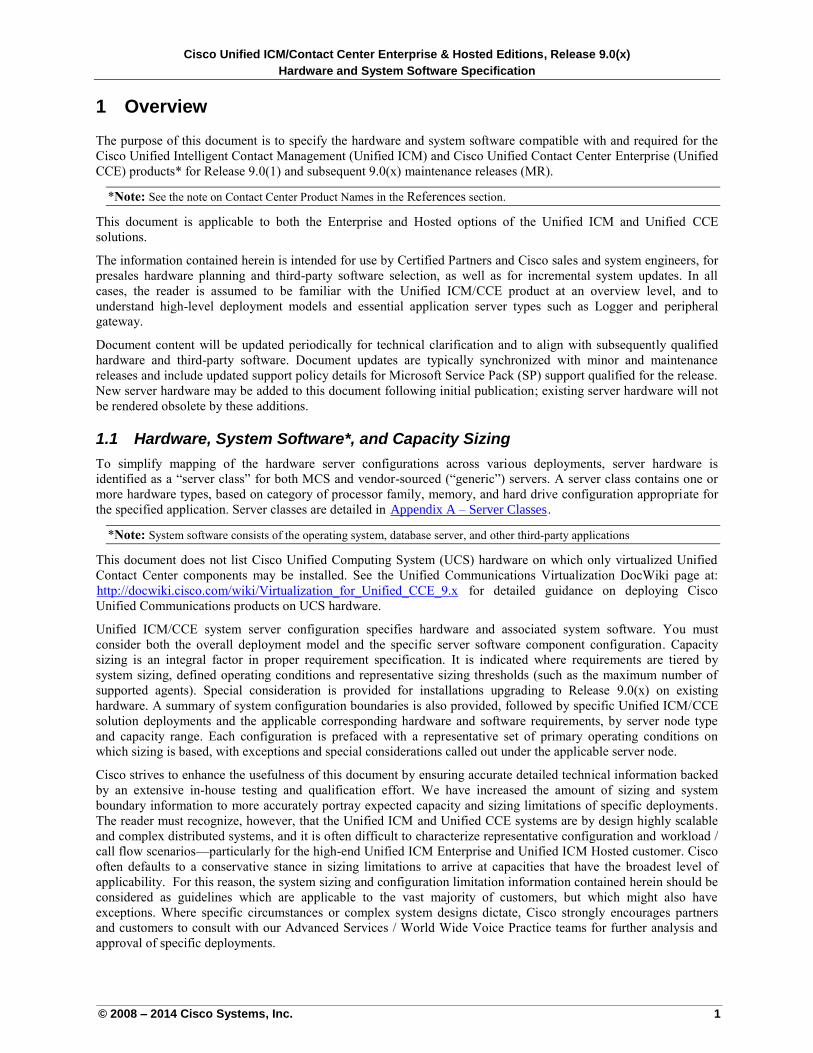
1 Overview
The purpose of this document is to specify the hardware and system software compatible with and required for the
Cisco Unified Intelligent Contact Management (Unified ICM) and Cisco Unified Contact Center Enterprise (Unified
CCE) products* for Release 9.0(1) and subsequent 9.0(x) maintenance releases (MR).
*Note: See the note on Contact Center Product Names in the References section.
This document is applicable to both the Enterprise and Hosted options of the Unified ICM and Unified CCE
solutions.
The information contained herein is intended for use by Certified Partners and Cisco sales and system engineers, for
presales hardware planning and third-party software selection, as well as for incremental system updates. In all
cases, the reader is assumed to be familiar with the Unified ICM/CCE product at an overview level, and to
understand high-level deployment models and essential application server types such as Logger and peripheral
gateway.
Document content will be updated periodically for technical clarification and to align with subsequently qualified
hardware and third-party software. Document updates are typically synchronized with minor and maintenance
releases and include updated support policy details for Microsoft Service Pack (SP) support qualified for the release.
New server hardware may be added to this document following initial publication; existing server hardware will not
be rendered obsolete by these additions.
1.1 Hardware, System Software*, and Capacity Sizing
To simplify mapping of the hardware server configurations across various deployments, server hardware is
identified as a “server class” for both MCS and vendor-sourced (“generic”) servers. A server class contains one or
more hardware types, based on category of processor family, memory, and hard drive configuration appropriate for
the specified application. Server classes are detailed in UAppendix A – Server ClassesU.
*Note: System software consists of the operating system, database server, and other third-party applications
This document does not list Cisco Unified Computing System (UCS) hardware on which only virtualized Unified
Contact Center components may be installed. See the Unified Communications Virtualization DocWiki page at:
Uhttp://docwiki.cisco.com/wiki/Virtualization_for_Unified_CCE_9.x U for detailed guidance on deploying Cisco
Unified Communications products on UCS hardware.
Unified ICM/CCE system server configuration specifies hardware and associated system software. You must
consider both the overall deployment model and the specific server software component configuration. Capacity
sizing is an integral factor in proper requirement specification. It is indicated where requirements are tiered by
system sizing, defined operating conditions and representative sizing thresholds (such as the maximum number of
supported agents). Special consideration is provided for installations upgrading to Release 9.0(x) on existing
hardware. A summary of system configuration boundaries is also provided, followed by specific Unified ICM/CCE
solution deployments and the applicable corresponding hardware and software requirements, by server node type
and capacity range. Each configuration is prefaced with a representative set of primary operating conditions on
which sizing is based, with exceptions and special considerations called out under the applicable server node.
Cisco strives to enhance the usefulness of this document by ensuring accurate detailed technical information backed
by an extensive in-house testing and qualification effort. We have increased the amount of sizing and system
boundary information to more accurately portray expected capacity and sizing limitations of specific deployments.
The reader must recognize, however, that the Unified ICM and Unified CCE systems are by design highly scalable
and complex distributed systems, and it is often difficult to characterize representative configuration and workload /
call flow scenarios—particularly for the high-end Unified ICM Enterprise and Unified ICM Hosted customer. Cisco
often defaults to a conservative stance in sizing limitations to arrive at capacities that have the broadest level of
applicability. For this reason, the system sizing and configuration limitation information contained herein should be
considered as guidelines which are applicable to the vast majority of customers, but which might also have
exceptions. Where specific circumstances or complex system designs dictate, Cisco strongly encourages partners
and customers to consult with our Advanced Services / World Wide Voice Practice teams for further analysis and
approval of specific deployments.
Cisco Unified ICM/Contact Center Enterprise & Hosted Editions, Release 9.0(x)
Hardware and System Software Specification
© 2008 – 2014 Cisco Systems, Inc. 2
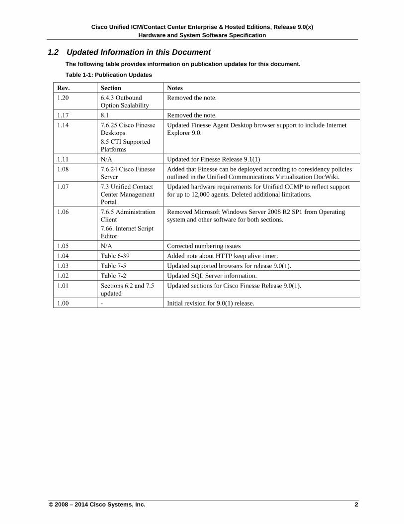
1.2 Updated Information in this Document
The following table provides information on publication updates for this document.
Table 1-1: Publication Updates
Rev. Section Notes
1.20 6.4.3 Outbound
Option Scalability
Removed the note.
1.17 8.1 Removed the note.
1.14 7.6.25 Cisco Finesse
Desktops
8.5 CTI Supported
Platforms
Updated Finesse Agent Desktop browser support to include Internet
Explorer 9.0.
1.11 N/A Updated for Finesse Release 9.1(1)
1.08 7.6.24 Cisco Finesse
Server
Added that Finesse can be deployed according to coresidency policies
outlined in the Unified Communications Virtualization DocWiki.
1.07 7.3 Unified Contact
Center Management
Portal
Updated hardware requirements for Unified CCMP to reflect support
for up to 12,000 agents. Deleted additional limitations.
1.06 7.6.5 Administration
Client
7.66. Internet Script
Editor
Removed Microsoft Windows Server 2008 R2 SP1 from Operating
system and other software for both sections.
1.05 N/A Corrected numbering issues
1.04 Table 6-39 Added note about HTTP keep alive timer.
1.03 Table 7-5 Updated supported browsers for release 9.0(1).
1.02 Table 7-2 Updated SQL Server information.
1.01 Sections 6.2 and 7.5
updated
Updated sections for Cisco Finesse Release 9.0(1).
1.00 - Initial revision for 9.0(1) release.
Cisco Unified ICM/Contact Center Enterprise & Hosted Editions, Release 9.0(x)
Hardware and System Software Specification
© 2008 – 2014 Cisco Systems, Inc. 3
2 References
Cisco Unified Intelligent Contact Management/Unified Contact Center Enterprise and Hosted (Unified ICME and
Unified ICMH) product information can be found on Uwww.cisco.comU.
Product documentation, including planning, upgrade, installation, configuration, reporting, reference, and developer
documentation, is available at: UCisco Product SupportU.
Other useful documents include:
Cisco Unified ICM Software ACD Supplements
Uhttp://www.cisco.com/en/US/products/sw/custcosw/ps1844/prod_technical_reference_list.html
Cisco Unified ICM ACD PG Supportability Matrices
Uhttp://www.cisco.com/en/US/docs/voice_ip_comm/cust_contact/contact_center/ipcc_enterprise/compatibili
ty_matrix/icmacdmx.pdfU
Cisco Unified Contact Center Enterprise Software Compatibility Guide
Uhttp://docwiki.cisco.com/wiki/Compatibility_Matrix_for_Unified_CCE U
Cisco End-of-Life and End-of-Sale Notices
Uhttp://www.cisco.com/en/US/products/sw/custcosw/ps1001/prod_eol_notices_list.htmlU
Cisco Unified Contact Center Enterprise 9.x Solution Reference Network Design (SRND)
Uhttp://www.cisco.com/en/US/products/sw/custcosw/ps1844/products_implementation_design_guides_list.h
tmlU
Cisco Unified Customer Voice Portal Solution Reference Network Design (SRND)
Uhttp://www.cisco.com/en/US/products/sw/custcosw/ps1006/products_implementation_design_guides_list.h
tmlU
Virtualization Guide for Cisco Unified Intelligent Contact Management and Contact Center Enterprise
Uhttps://www.cisco.com/en/US/docs/voice_ip_comm/cust_contact/contact_center/icm_enterprise/icm_enter
prise_7_5/user/guide/VirtualizationGde753.pdfU
Bill of Material Guide for Cisco Unified Intelligence Center
Uhttp://www.cisco.com/en/US/docs/voice_ip_comm/cust_contact/contact_center/intelligence_suite/intellige
nce_suite_852/Design/guide/UnifiedIntellCenterBOM_852.pdf U
Cisco Unified Customer Voice Portal Hardware and System Software Specification
Uhttp://www.cisco.com/en/US/products/sw/custcosw/ps1006/products_implementation_design_guides_list.h
tmlU
Note: The documents listed above are not necessarily updated on the same schedule as the Hardware and System
Software Specification (Bill of Materials). For that reason, specification data might differ between this
document and the references cited. For Unified ICM/CCE 9.0, see the most recent revision of these
documents or those revisions listed within the specific Unified ICM/CCE release heading on Cisco.com.
The use of the generic abbreviation “Unified ICM” is intended to include both Unified ICMH and Unified ICME.
The use of the generic abbreviation “Unified CCE” in this document is intended to include Unified CCH and
Unified CCE, but not Cisco Unified Contact Center Express (Unified CCX).
Cisco Unified ICM/Contact Center Enterprise & Hosted Editions, Release 9.0(x)
Hardware and System Software Specification
© 2008 – 2014 Cisco Systems, Inc. 4
3 Servers for Cisco Contact Center Products
The Cisco Unified Contact Center Enterprise 9.0(x) product is fully supported on Cisco Unified Computing System
(UCS) servers in a virtualized environment. See UUnified Communications in a Virtualized Environment U for more
details about this deployment option.
The Unified ICM/CCE solutions are fully supported on the Cisco 7800 Series Media Convergence Server (MCS)
family of Intel-based, high-performance hardware servers. The MCS 7800 family is an integral part of a complete
and scalable Cisco Voice architecture solution for the enterprise, thoroughly tested for compatibility and optimal
performance with the Unified ICM/ CCE product. MCS servers have a proven track record of high reliability, offer a
common consistent architecture across Cisco Voice applications, and accommodate value-added Cisco support
services such as SMARTnet (technical support services).
The range of MCS server sizes aligns with specific Unified ICM/CCE server node types and the corresponding
anticipated capacity of a given solution. As explained in the UOverviewU section, and as listed in UAppendix A – Server
ClassesU, MCS servers are categorized in this document by “server class” designation. Specific classes are, in turn,
listed as applicable to a given Unified ICM/CCE server node type and capacity in, UUnified ICM/Unified Contact
Center Operating ConditionsU. Where specific Unified ICM/CCE component server requirements dictate certain
hardware capabilities (for example, SAS-II disk drives for high transaction SQL Server deployments, or dual
processor configurations to achieve specific system performance metrics), the applicable MCS servers are depicted.
Full detail on the range of MCS servers and their features can be found at the following reference:
Uhttp://www.cisco.com/go/mcsU.
Unlike the Cisco Unified Communications Manager (Unified CM) and associated products, MCS servers ordered
for Unified ICM/CCE deployments do not include a customized distribution of the operating system. Users ordering
MCS for Unified ICM/CCE must also order the appropriate editions of Microsoft Windows Server 2008 R2, and, for
database, SQL Server 2008 64-bit. Unified ICM/CCE MCS customers assume primary maintenance responsibility
for their Windows environment.
Beginning with Release 8.5, a virtualized UCS server solution or an MCS server solution is required for all Cisco
Unified Contact Center Enterprise deployments. Only exact-match OEM servers from Cisco-selected manufacturers
(see Uhttp://www.cisco.com/go/swonlyU for details), or generic hardware for those components specifically indicated,
can be substituted for Cisco UCS or MCS servers for Unified Contact Center Enterprise deployments. This
requirement applies to new deployments and expansions on physical servers as well as on ESX server.
If you have non-MCS hardware, you can upgrade to a 9.0 release and remain on that hardware as long as your
hardware specifications comply with UAppendix A – Server ClassesU and your contact center capacity requirements
are within the capacity limits listed in USoftware Constraints and Operating ConditionsU. For Unified ICME and
Unified ICMH customers, non-MCS (“generic”) servers that essentially match MCS specifications for a given server
class can be deployed; these are separately specified in UAppendix A – Server ClassesU. Note that high-end carrier-
class generic servers are specified for specific applications that have no current MCS equivalent.
Cisco Unified ICM/Contact Center Enterprise & Hosted Editions, Release 9.0(x)
Hardware and System Software Specification
© 2008 – 2014 Cisco Systems, Inc. 5
3.1 Server Hardware Configuration Guidelines
This section provides system integrators and customers with guidelines, supported and unsupported server
hardware, and storage configurations. Cisco MCS servers prepackage a number of the specified options; however,
Cisco Unified ICM and Unified CCE applications require special consideration to meet the high performance
demands of the system. Whether you are acquiring Cisco MCS servers or third-party hardware, take special care
to choose the appropriate level of hardware redundancy and a storage solution specific to the application nodes for
which the servers are intended. Of particular importance are the storage controller, number (and capacity) of
disks, and RAID configuration available. Additional guidelines are provided, for customers with large
configurations and those that require long historical data retention periods.
Note that Cisco does not currently fully support deployment of the Unified ICM/CCE solution on a third-party
server “blade” chassis form factor.
Note: When you plan a “technology refresh” upgrade for a Peripheral Gateway(PG), ensure at least 40 GB of
hard disk space free to ensure that the OPC capture serviceability feature, when enabled, will have
sufficient disk space available. This capability is vital for troubleshooting PG-related issues.
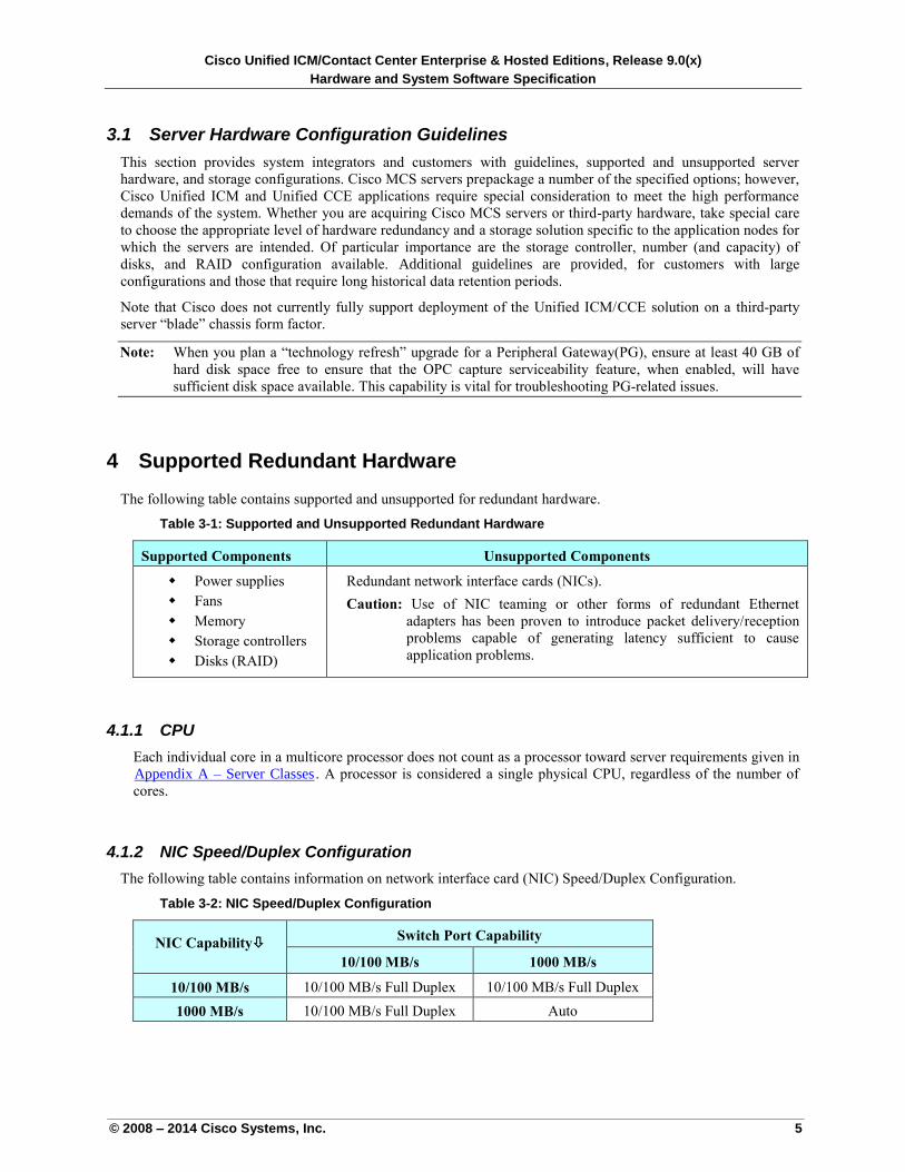
4 Supported Redundant Hardware
The following table contains supported and unsupported for redundant hardware.
Table 3-1: Supported and Unsupported Redundant Hardware
Supported Components Unsupported Components
Power supplies
Fans
Memory
Storage controllers
Disks (RAID)
Redundant network interface cards (NICs).
Caution: Use of NIC teaming or other forms of redundant Ethernet
adapters has been proven to introduce packet delivery/reception
problems capable of generating latency sufficient to cause
application problems.
4.1.1 CPU
Each individual core in a multicore processor does not count as a processor toward server requirements given in
UAppendix A – Server ClassesU. A processor is considered a single physical CPU, regardless of the number of
cores.
4.1.2 NIC Speed/Duplex Configuration
The following table contains information on network interface card (NIC) Speed/Duplex Configuration.
Table 3-2: NIC Speed/Duplex Configuration
NIC Capability Switch Port Capability
10/100 MB/s 1000 MB/s
10/100 MB/s 10/100 MB/s Full Duplex 10/100 MB/s Full Duplex
1000 MB/s 10/100 MB/s Full Duplex Auto
Cisco Unified ICM/Contact Center Enterprise & Hosted Editions, Release 9.0(x)
Hardware and System Software Specification
© 2008 – 2014 Cisco Systems, Inc. 6
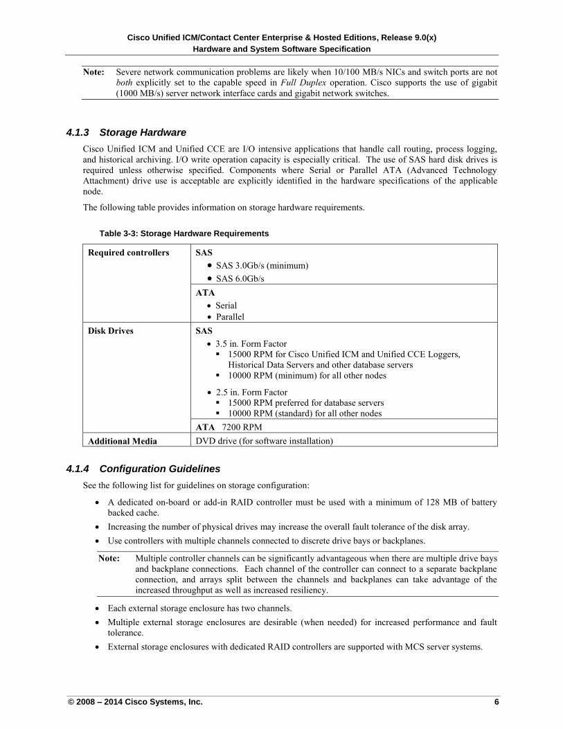
Note: Severe network communication problems are likely when 10/100 MB/s NICs and switch ports are not
both explicitly set to the capable speed in Full Duplex operation. Cisco supports the use of gigabit
(1000 MB/s) server network interface cards and gigabit network switches.
4.1.3 Storage Hardware
Cisco Unified ICM and Unified CCE are I/O intensive applications that handle call routing, process logging,
and historical archiving. I/O write operation capacity is especially critical. The use of SAS hard disk drives is
required unless otherwise specified. Components where Serial or Parallel ATA (Advanced Technology
Attachment) drive use is acceptable are explicitly identified in the hardware specifications of the applicable
node.
The following table provides information on storage hardware requirements.
Table 3-3: Storage Hardware Requirements
Required controllers
SAS
SAS 3.0Gb/s (minimum)
SAS 6.0Gb/s
ATA
Serial
Parallel
Disk Drives
SAS
3.5 in. Form Factor
15000 RPM for Cisco Unified ICM and Unified CCE Loggers,
Historical Data Servers and other database servers
10000 RPM (minimum) for all other nodes
2.5 in. Form Factor
15000 RPM preferred for database servers
10000 RPM (standard) for all other nodes
ATA 7200 RPM
Additional Media DVD drive (for software installation)
4.1.4 Configuration Guidelines
See the following list for guidelines on storage configuration:
A dedicated on-board or add-in RAID controller must be used with a minimum of 128 MB of battery
backed cache.
Increasing the number of physical drives may increase the overall fault tolerance of the disk array.
Use controllers with multiple channels connected to discrete drive bays or backplanes.
Note: Multiple controller channels can be significantly advantageous when there are multiple drive bays
and backplane connections. Each channel of the controller can connect to a separate backplane
connection, and arrays split between the channels and backplanes can take advantage of the
increased throughput as well as increased resiliency.
Each external storage enclosure has two channels.
Multiple external storage enclosures are desirable (when needed) for increased performance and fault
tolerance.
External storage enclosures with dedicated RAID controllers are supported with MCS server systems.
Cisco Unified ICM/Contact Center Enterprise & Hosted Editions, Release 9.0(x)
Hardware and System Software Specification
© 2008 – 2014 Cisco Systems, Inc. 7
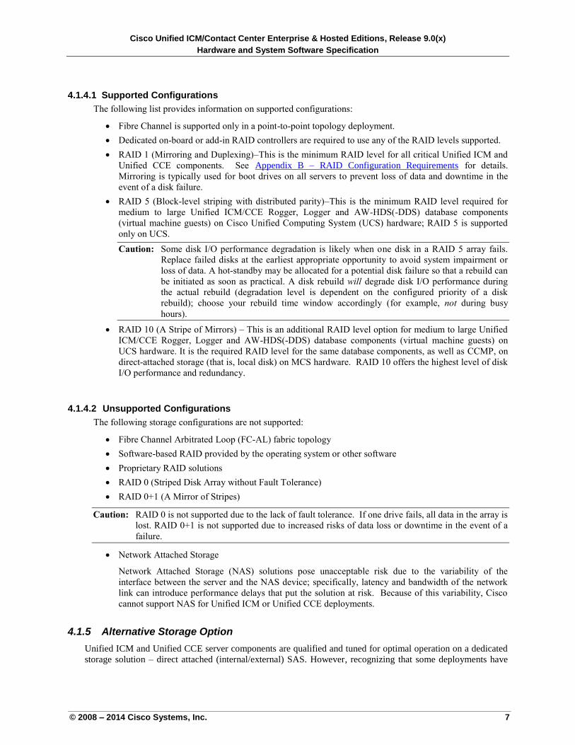
4.1.4.1 Supported Configurations
The following list provides information on supported configurations:
Fibre Channel is supported only in a point-to-point topology deployment.
Dedicated on-board or add-in RAID controllers are required to use any of the RAID levels supported.
RAID 1 (Mirroring and Duplexing)–This is the minimum RAID level for all critical Unified ICM and
Unified CCE components. See UAppendix B – RAID Configuration RequirementsU for details.
Mirroring is typically used for boot drives on all servers to prevent loss of data and downtime in the
event of a disk failure.
RAID 5 (Block-level striping with distributed parity)–This is the minimum RAID level required for
medium to large Unified ICM/CCE Rogger, Logger and AW-HDS(-DDS) database components
(virtual machine guests) on Cisco Unified Computing System (UCS) hardware; RAID 5 is supported
only on UCS.
Caution: Some disk I/O performance degradation is likely when one disk in a RAID 5 array fails.
Replace failed disks at the earliest appropriate opportunity to avoid system impairment or
loss of data. A hot-standby may be allocated for a potential disk failure so that a rebuild can
be initiated as soon as practical. A disk rebuild will degrade disk I/O performance during
the actual rebuild (degradation level is dependent on the configured priority of a disk
rebuild); choose your rebuild time window accordingly (for example, not during busy
hours).
RAID 10 (A Stripe of Mirrors) – This is an additional RAID level option for medium to large Unified
ICM/CCE Rogger, Logger and AW-HDS(-DDS) database components (virtual machine guests) on
UCS hardware. It is the required RAID level for the same database components, as well as CCMP, on
direct-attached storage (that is, local disk) on MCS hardware. RAID 10 offers the highest level of disk
I/O performance and redundancy.
4.1.4.2 4BUnsupported Configurations
The following storage configurations are not supported:
Fibre Channel Arbitrated Loop (FC-AL) fabric topology
Software-based RAID provided by the operating system or other software
Proprietary RAID solutions
RAID 0 (Striped Disk Array without Fault Tolerance)
RAID 0+1 (A Mirror of Stripes)
Caution: RAID 0 is not supported due to the lack of fault tolerance. If one drive fails, all data in the array is
lost. RAID 0+1 is not supported due to increased risks of data loss or downtime in the event of a
failure.
Network Attached Storage
Network Attached Storage (NAS) solutions pose unacceptable risk due to the variability of the
interface between the server and the NAS device; specifically, latency and bandwidth of the network
link can introduce performance delays that put the solution at risk. Because of this variability, Cisco
cannot support NAS for Unified ICM or Unified CCE deployments.
4.1.5 Alternative Storage Option
Unified ICM and Unified CCE server components are qualified and tuned for optimal operation on a dedicated
storage solution – direct attached (internal/external) SAS. However, recognizing that some deployments have
Cisco Unified ICM/Contact Center Enterprise & Hosted Editions, Release 9.0(x)
Hardware and System Software Specification
© 2008 – 2014 Cisco Systems, Inc. 8
data retention needs that exceed the storage capabilities of direct attached disk arrays, Cisco does endorse the
use of a Storage Area Network (SAN) under the following conditions:
1. A SAN RAID group must be dedicated to Unified ICM/CCE database components; these SAN RAID
groups must not be shared by other applications.
2. The SAN host interface (for example, Fibre Channel) must meet or exceed the performance
specifications of supported (direct attached) SAS interfaces. See UStorage Hardware, Required
ControllersU.
3. Each individual drive in the SAN array must meet or exceed the performance specifications of
supported (direct attached) disk drives. See UStorage Hardware, Disk SpeedU.
Note: SATA drives are not supported with SAN.
4. The SAN disk array must be configured as RAID 5 or RAID 10, for added performance and fault
tolerance.
SAN solutions are typically deployed in a shared environment where multiple applications are contending for
storage access. Because of the real-time nature of the Unified ICM/CCE application, a shared disk environment
cannot be supported (for example, Unified CCE application component sharing a LUN with another
application); the conditions listed above are necessary to ensure that the deployment performs within published
capacity limits. If the SAN storage deployment is identified as affecting the functions of the Unified CCE
solution, you will be required to deploy a direct attached storage solution instead. Moreover, if in the process of
troubleshooting, the SAN itself is identified as the problem, contact the system integrator or the SAN vendor for
resolution.
4.1.6 Unqualified Backup Options
Backup device/software option decisions (and procedures) are left to the end customer; no backup products are
explicitly qualified by Cisco.
Caution: For performance reasons, backups must be performed outside of business hours or during periods of
lowest activity. Cisco does not provide recommendations for specific backup devices or products,
but internal and other direct-attached devices might have restrictions as to which platforms they are
compatible with. Consult your backup product vendor to determine options for internal or external
backup storage.
Cisco Unified ICM/Contact Center Enterprise & Hosted Editions, Release 9.0(x)
Hardware and System Software Specification
© 2008 – 2014 Cisco Systems, Inc. 9
5 Software Upgrade and Installation Considerations
For information about upgrading to Unified ICM/CCE, Release 9.0(1), see the Upgrade Guide for ICM and CTI
OS for Cisco Unified Contact Center Enterprise, Release 9.0(1). For additional information on Release 9.0(1)
upgrade and installation, see also the Release Notes for Cisco Unified Contact Center Enterprise, Release 9.0(1).
For information about upgrading to Unified ICM/CCE, Release 8.5(2), see the Upgrade Guide for ICM and CTI
OS for Cisco Unified Contact Center Enterprise, Release 8.5(2). For additional information on Release 8.5(2)
upgrade and installation, see also the Release Notes for Cisco Unified Contact Center Enterprise, Release 8.5(2).
Cisco Unified ICM/Contact Center Enterprise & Hosted Editions, Release 9.0(x)
Hardware and System Software Specification
© 2008 – 2014 Cisco Systems, Inc. 10
6 Software Scalability, Constraints, and Operating Conditions
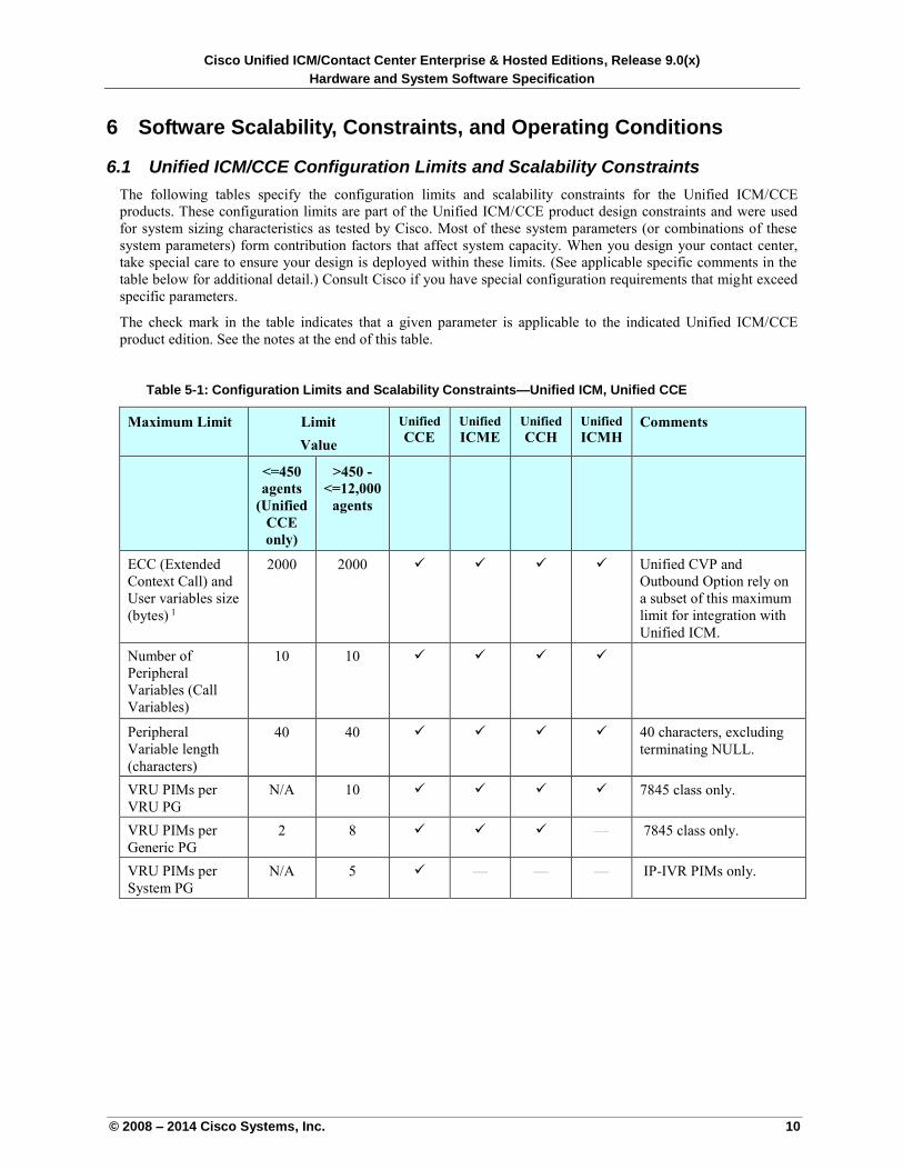
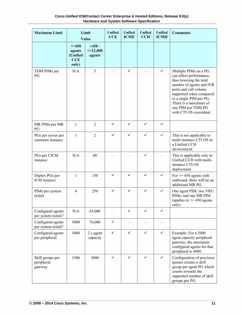
6.1 Unified ICM/CCE Configuration Limits and Scalability Constraints
The following tables specify the configuration limits and scalability constraints for the Unified ICM/CCE
products. These configuration limits are part of the Unified ICM/CCE product design constraints and were used
for system sizing characteristics as tested by Cisco. Most of these system parameters (or combinations of these
system parameters) form contribution factors that affect system capacity. When you design your contact center,
take special care to ensure your design is deployed within these limits. (See applicable specific comments in the
table below for additional detail.) Consult Cisco if you have special configuration requirements that might exceed
specific parameters.
The check mark in the table indicates that a given parameter is applicable to the indicated Unified ICM/CCE
product edition. See the notes at the end of this table.
Table 5-1: Configuration Limits and Scalability Constraints—Unified ICM, Unified CCE
Maximum Limit Limit
Value
Unified
CCE
Unified
ICME
Unified
CCH
Unified
ICMH
Comments
<=450
agents
(Unified
CCE
only)
>450 -
<=12,000
agents
ECC (Extended
Context Call) and
User variables size
(bytes) 1
2000 2000 Unified CVP and
Outbound Option rely on
a subset of this maximum
limit for integration with
Unified ICM.
Number of
Peripheral
Variables (Call
Variables)
10 10
Peripheral
Variable length
(characters)
40 40 40 characters, excluding
terminating NULL.
VRU PIMs per
VRU PG
N/A 10 7845 class only.
VRU PIMs per
Generic PG
2 8 — 7845 class only.
VRU PIMs per
System PG
N/A 5 — — — IP-IVR PIMs only.
Cisco Unified ICM/Contact Center Enterprise & Hosted Editions, Release 9.0(x)
Hardware and System Software Specification
© 2008 – 2014 Cisco Systems, Inc. 11
Maximum Limit Limit
Value
Unified
CCE
Unified
ICME
Unified
CCH
Unified
ICMH
Comments
<=450
agents
(Unified
CCE
only)
>450 -
<=12,000
agents
TDM PIMs per
PG
N/A 5 — — Multiple PIMs on a PG
can affect performance,
thus lowering the total
number of agents and IVR
ports and call volume
supported when compared
to a single PIM per PG.
There is a maximum of
one PIM per TDM PG
with CTI OS coresident.
MR PIMs per MR
PG
1 2
PGs per server per
customer instance
1 2 This is not applicable to
multi-instance CTI OS in
a Unified CCH
environment.
PGs per CICM
instance
N/A 80 — —
— This is applicable only to
Unified CCH with multi-
instance CTI OS
deployment.
Duplex PGs per
ICM instance
1 150 For <= 450 agents with
outbound, there will be an
additional MR PG.
PIMs per system
(total)
4 250 One agent PIM, two VRU
PIMs, and one MR PIM
(applies to >= 450 agents
only).
Configured agents
per system (total) 2
N/A 65,000 —
Configured agents
per system (total)2
3000 76,000 — — —
Configured agents
per peripheral
3000 2 x agent
capacity
Example: For a 2000
agent capacity peripheral
gateway, the maximum
configured agents for that
peripheral is 4000.
Skill groups per
peripheral
gateway
1500 3000 Configuration of precision
queues creates a skill
group per agent PG which
counts towards the
supported number of skill
groups per PG.
Cisco Unified ICM/Contact Center Enterprise & Hosted Editions, Release 9.0(x)
Hardware and System Software Specification
© 2008 – 2014 Cisco Systems, Inc. 12
Maximum Limit Limit
Value
Unified
CCE
Unified
ICME
Unified
CCH
Unified
ICMH
Comments
<=450
agents
(Unified
CCE
only)
>450 -
<=12,000
agents
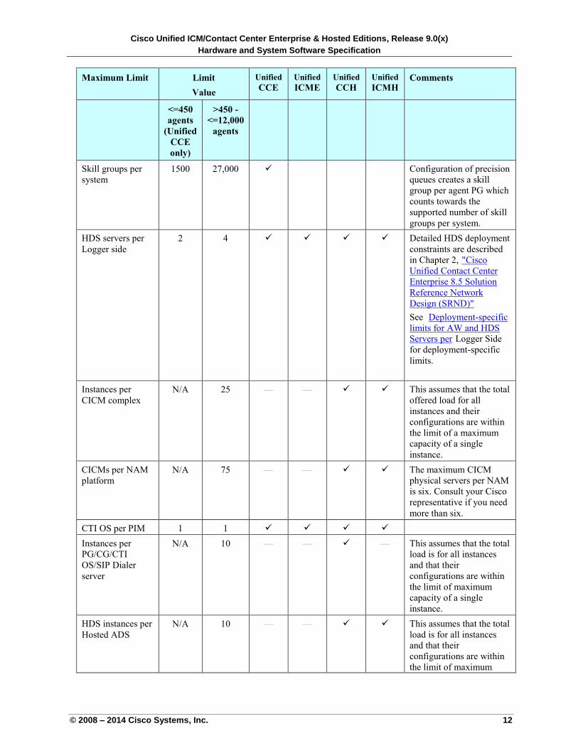
Skill groups per
system
1500 27,000 Configuration of precision
queues creates a skill
group per agent PG which
counts towards the
supported number of skill
groups per system.
HDS servers per
Logger side
2 4 Detailed HDS deployment
constraints are described
in Chapter 2, U"Cisco
Unified Contact Center
Enterprise 8.5 Solution
Reference Network
Design (SRND)" U
See UDeployment-specific
limits for AW and HDS
Servers perU Logger Side
for deployment-specific
limits.
Instances per
CICM complex
N/A 25 — — This assumes that the total
offered load for all
instances and their
configurations are within
the limit of a maximum
capacity of a single
instance.
CICMs per NAM
platform
N/A 75 — — The maximum CICM
physical servers per NAM
is six. Consult your Cisco
representative if you need
more than six.
CTI OS per PIM 1 1
Instances per
PG/CG/CTI
OS/SIP Dialer
server
N/A 10 — — — This assumes that the total
load is for all instances
and that their
configurations are within
the limit of maximum
capacity of a single
instance.
HDS instances per
Hosted ADS
N/A 10 — — This assumes that the total
load is for all instances
and that their
configurations are within
the limit of maximum
Cisco Unified ICM/Contact Center Enterprise & Hosted Editions, Release 9.0(x)
Hardware and System Software Specification
© 2008 – 2014 Cisco Systems, Inc. 13
Maximum Limit Limit
Value
Unified
CCE
Unified
ICME
Unified
CCH
Unified
ICMH
Comments
<=450
agents
(Unified
CCE
only)
>450 -
<=12,000
agents
capacity of a single
instance.
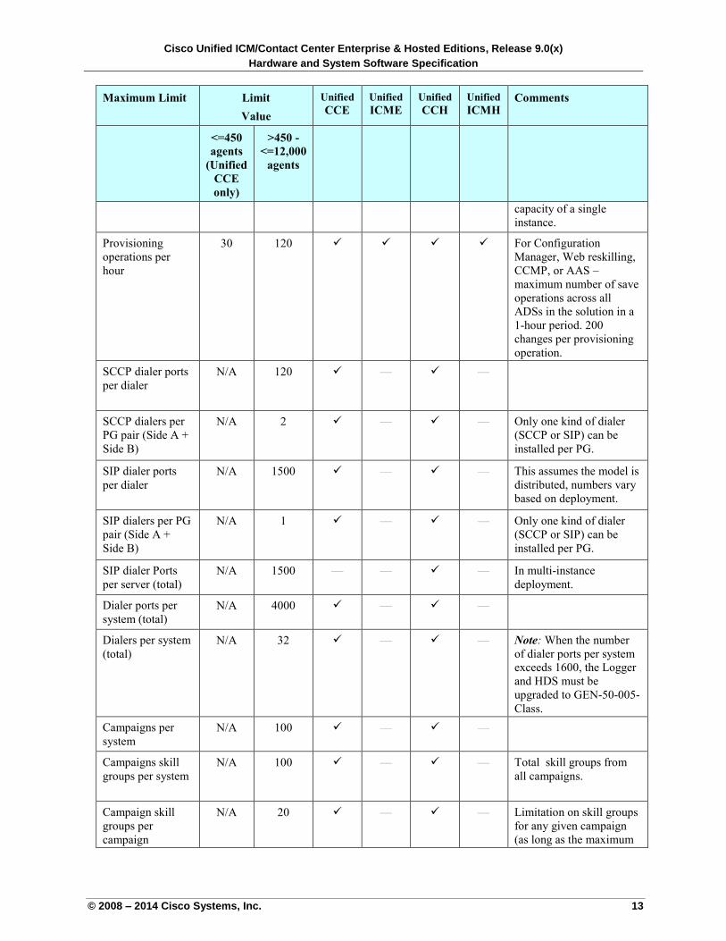
Provisioning
operations per
hour
30 120 For Configuration
Manager, Web reskilling,
CCMP, or AAS –
maximum number of save
operations across all
ADSs in the solution in a
1-hour period. 200
changes per provisioning
operation.
SCCP dialer ports
per dialer
N/A 120 — —
SCCP dialers per
PG pair (Side A +
Side B)
N/A 2 — — Only one kind of dialer
(SCCP or SIP) can be
installed per PG.
SIP dialer ports
per dialer
N/A 1500 — — This assumes the model is
distributed, numbers vary
based on deployment.
SIP dialers per PG
pair (Side A +
Side B)
N/A 1 — — Only one kind of dialer
(SCCP or SIP) can be
installed per PG.
SIP dialer Ports
per server (total)
N/A 1500 — — — In multi-instance
deployment.
Dialer ports per
system (total)
N/A 4000 — —
Dialers per system
(total)
N/A 32 — — Note: When the number
of dialer ports per system
exceeds 1600, the Logger
and HDS must be
upgraded to GEN-50-005-
Class.
Campaigns per
system
N/A 100 — —
Campaigns skill
groups per system
N/A 100 — — Total skill groups from
all campaigns.
Campaign skill
groups per
campaign
N/A 20 — — Limitation on skill groups
for any given campaign
(as long as the maximum
Cisco Unified ICM/Contact Center Enterprise & Hosted Editions, Release 9.0(x)
Hardware and System Software Specification
© 2008 – 2014 Cisco Systems, Inc. 14
Maximum Limit Limit
Value
Unified
CCE
Unified
ICME
Unified
CCH
Unified
ICMH
Comments
<=450
agents
(Unified
CCE
only)
>450 -
<=12,000
agents
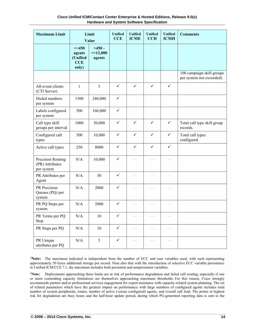
100 campaign skill groups
per system not exceeded).
All-event clients
(CTI Server)
1 5
Dialed numbers
per system
1500 240,000
Labels configured
per system
500 160,000
Call type skill
groups per interval
1000 30,000 Total call type skill group
records.
Configured call
types
500 10,000 Total call types
configured.
Active call types 250 8000
Precision Routing
(PR) Attributes
per system
N/A 10,000 — — —
PR Attributes per
Agent
N/A 50 — — —
PR Precision
Queues (PQ) per
system
N/A 2000 — — —
PR PQ Steps per
system
N/A 5000 — — —
PR Terms per PQ
Step
N/A 10 — — —
PR Steps per PQ N/A 10 — — —
PR Unique
attributes per PQ
N/A 5 — — —
1Note: The maximum indicated is independent from the number of ECC and user variables used, with each representing
approximately 50 bytes additional storage per record. Note also that with the introduction of selective ECC variable persistence in Unified ICM/CCE 7.1, the maximum includes both persistent and nonpersistent variables.
2Note: Deployments approaching these limits are at risk of performance degradation and failed call routing, especially if one
or more contending capacity limitations are themselves approaching maximum thresholds. For this reason, Cisco strongly
recommends partner and/or professional services engagement for expert assistance with capacity-related system planning. The set
of related parameters which have the greatest impact on performance with large numbers of configured agents includes total
number of system peripherals, routes, number of active (versus configured) agents, and overall call load. The points at highest
risk for degradation are busy hours and the half-hour update period, during which PG-generated reporting data is sent to the
Cisco Unified ICM/Contact Center Enterprise & Hosted Editions, Release 9.0(x)
Hardware and System Software Specification
© 2008 – 2014 Cisco Systems, Inc. 15
Central Controller. System administrators can lessen their exposure to these issues by purging unused configured agents, retiring inactive peripherals, and maintaining systems at current maintenance release levels.
Note: For Unified CCH running with SCCP dialer, there is only one instance of Outbound Option per CICM
platform/complex with a maximum of two dialers per PG pair.
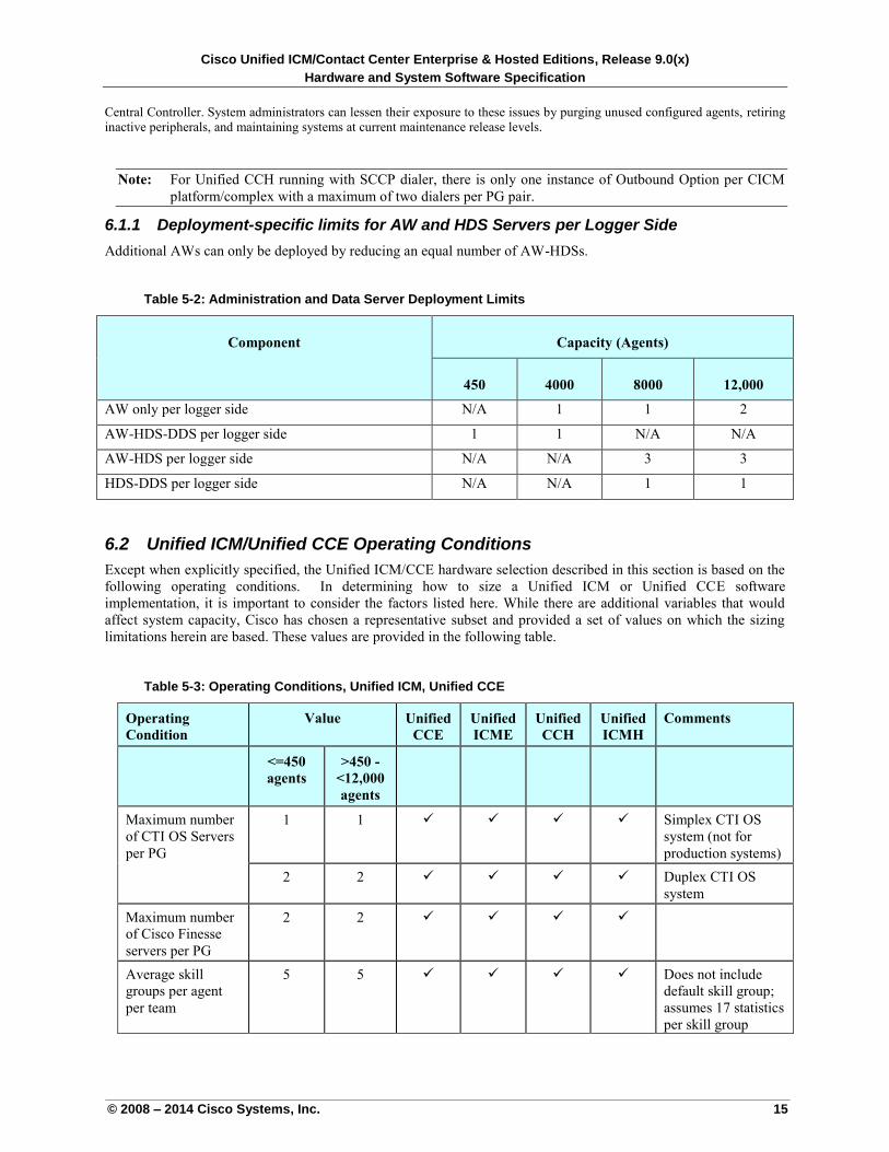
6.1.1 Deployment-specific limits for AW and HDS Servers per Logger Side
Additional AWs can only be deployed by reducing an equal number of AW-HDSs.
Table 5-2: Administration and Data Server Deployment Limits
Component Capacity (Agents)
450 4000 8000 12,000
AW only per logger side N/A 1 1 2
AW-HDS-DDS per logger side 1 1 N/A N/A
AW-HDS per logger side N/A N/A 3 3
HDS-DDS per logger side N/A N/A 1 1
6.2 Unified ICM/Unified CCE Operating Conditions
Except when explicitly specified, the Unified ICM/CCE hardware selection described in this section is based on the
following operating conditions. In determining how to size a Unified ICM or Unified CCE software
implementation, it is important to consider the factors listed here. While there are additional variables that would
affect system capacity, Cisco has chosen a representative subset and provided a set of values on which the sizing
limitations herein are based. These values are provided in the following table.
Table 5-3: Operating Conditions, Unified ICM, Unified CCE
Operating
Condition
Value Unified
CCE
Unified
ICME
Unified
CCH
Unified
ICMH
Comments
<=450
agents
>450 -
<12,000
agents
Maximum number
of CTI OS Servers
per PG
1 1 Simplex CTI OS
system (not for
production systems)
2 2 Duplex CTI OS
system
Maximum number
of Cisco Finesse
servers per PG
2 2
Average skill
groups per agent
per team
5 5 Does not include
default skill group;
assumes 17 statistics
per skill group
Cisco Unified ICM/Contact Center Enterprise & Hosted Editions, Release 9.0(x)
Hardware and System Software Specification
© 2008 – 2014 Cisco Systems, Inc. 16
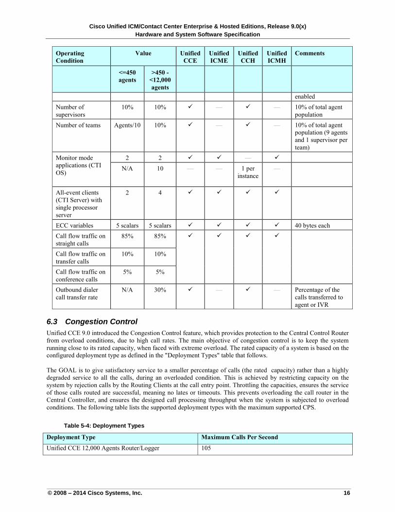
Operating
Condition
Value Unified
CCE
Unified
ICME
Unified
CCH
Unified
ICMH
Comments
<=450
agents
>450 -
<12,000
agents
enabled
Number of
supervisors
10% 10% — — 10% of total agent
population
Number of teams Agents/10 10% — — 10% of total agent
population (9 agents
and 1 supervisor per
team)
Monitor mode
applications (CTI
OS)
2 2 —
N/A 10 — — 1 per
instance
—
All-event clients
(CTI Server) with
single processor
server
2 4
ECC variables 5 scalars 5 scalars 40 bytes each
Call flow traffic on
straight calls
85% 85%
Call flow traffic on
transfer calls
10% 10%
Call flow traffic on
conference calls
5% 5%
Outbound dialer
call transfer rate
N/A 30% — — Percentage of the
calls transferred to
agent or IVR
6.3 Congestion Control
Unified CCE 9.0 introduced the Congestion Control feature, which provides protection to the Central Control Router
from overload conditions, due to high call rates. The main objective of congestion control is to keep the system
running close to its rated capacity, when faced with extreme overload. The rated capacity of a system is based on the
configured deployment type as defined in the "Deployment Types" table that follows.
The GOAL is to give satisfactory service to a smaller percentage of calls (the rated capacity) rather than a highly
degraded service to all the calls, during an overloaded condition. This is achieved by restricting capacity on the
system by rejection calls by the Routing Clients at the call entry point. Throttling the capacities, ensures the service
of those calls routed are successful, meaning no lates or timeouts. This prevents overloading the call router in the
Central Controller, and ensures the designed call processing throughput when the system is subjected to overload
conditions. The following table lists the supported deployment types with the maximum supported CPS.
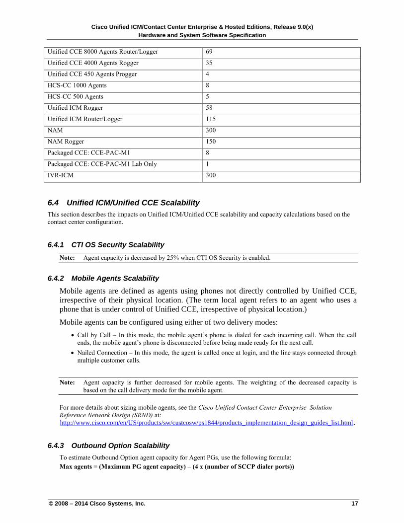
Table 5-4: Deployment Types
Deployment Type Maximum Calls Per Second
Unified CCE 12,000 Agents Router/Logger 105
Cisco Unified ICM/Contact Center Enterprise & Hosted Editions, Release 9.0(x)
Hardware and System Software Specification
© 2008 – 2014 Cisco Systems, Inc. 17
Unified CCE 8000 Agents Router/Logger 69
Unified CCE 4000 Agents Rogger 35
Unified CCE 450 Agents Progger 4
HCS-CC 1000 Agents 8
HCS-CC 500 Agents 5
Unified ICM Rogger 58
Unified ICM Router/Logger 115
NAM 300
NAM Rogger 150
Packaged CCE: CCE-PAC-M1 8
Packaged CCE: CCE-PAC-M1 Lab Only 1
IVR-ICM 300
6.4 Unified ICM/Unified CCE Scalability
This section describes the impacts on Unified ICM/Unified CCE scalability and capacity calculations based on the
contact center configuration.
6.4.1 CTI OS Security Scalability
Note: Agent capacity is decreased by 25% when CTI OS Security is enabled.
6.4.2 Mobile Agents Scalability
Mobile agents are defined as agents using phones not directly controlled by Unified CCE,
irrespective of their physical location. (The term local agent refers to an agent who uses a
phone that is under control of Unified CCE, irrespective of physical location.)
Mobile agents can be configured using either of two delivery modes:
Call by Call – In this mode, the mobile agent’s phone is dialed for each incoming call. When the call
ends, the mobile agent’s phone is disconnected before being made ready for the next call.
Nailed Connection – In this mode, the agent is called once at login, and the line stays connected through
multiple customer calls.
Note: Agent capacity is further decreased for mobile agents. The weighting of the decreased capacity is
based on the call delivery mode for the mobile agent.
For more details about sizing mobile agents, see the Cisco Unified Contact Center Enterprise Solution
Reference Network Design (SRND) at:
Uhttp://www.cisco.com/en/US/products/sw/custcosw/ps1844/products_implementation_design_guides_list.html U.
6.4.3 Outbound Option Scalability
To estimate Outbound Option agent capacity for Agent PGs, use the following formula:
Max agents = (Maximum PG agent capacity) – (4 x (number of SCCP dialer ports))
Cisco Unified ICM/Contact Center Enterprise & Hosted Editions, Release 9.0(x)
Hardware and System Software Specification
© 2008 – 2014 Cisco Systems, Inc. 18
or
Max agents = (Maximum PG agent capacity) – (1.33 x (number of SIP dialer ports))
These formulas indicate platform capacity; they are not an indicator of outbound resources in terms of how
many agents can be kept busy by the number of dialer ports in the deployment. A quick but inexact estimate is
2 ports required for each outbound agent, but your outbound resources may vary depending on hit rate, abandon
limit, and talk time for the campaigns in the deployment. Use the sizing tool to determine outbound
resources required for your campaigns.
See the Outbound Option chapter of the SRND at:
Uhttp://www.cisco.com/en/US/products/sw/custcosw/ps1844/products_implementation_design_guides_list.html U
for more details.
6.4.4 Agent Greeting Scalability
For deployments implementing the Agent Greeting feature, component scalability is affected by this feature.
For more details about sizing Agent Greeting deployments, see the Cisco Unified Contact Center Enterprise
Release 9.x Solution Reference Network Design (SRND) at:
Uhttp://www.cisco.com/en/US/products/sw/custcosw/ps1844/products_implementation_design_guides_list.html U.
Cisco Unified ICM/Contact Center Enterprise & Hosted Editions, Release 9.0(x)
Hardware and System Software Specification
© 2008 – 2014 Cisco Systems, Inc. 19
7 Server Hardware Requirements
7.1 Cisco Unified Contact Center Enterprise
This section helps you select the hardware servers for your Unified Contact Center Enterprise solution, including
both the Unified CCE and its associated deployment models.
VRU ports for Agent Peripheral Gateway (PG) and System PG should not exceed half of the maximum supported
agents listed in the capacity column. You can deploy additional VRU PGs to accommodate a greater number of
VRU ports. For VRU PG capacities, see the UVRU Peripheral Gateway (PG)U section.
UImportant Notes on Agent Capacity Calculation
For the following sections, the agent count in the capacity specification refers to the number of concurrently
logged-in agents. Consider the following factors when sizing call center resources:
CTI OS – For information about CTI OS capacity impact, see the UCTI OS Security ScalabilityU section.
Outbound Option – For information about determining Agent PG Outbound Option agent capacity, see
the UOutbound Option ScalabilityU section.
Note: All outbound call scenarios are supported when a mobile agent is deployed using nailed connection
call delivery mode. Outbound call scenarios are not supported when a mobile agent is deployed using call-
by-call call delivery mode.
Mobile Agents – See the UMobile Agents ScalabilityU section for factors that affect scalability.
Agent Greeting – For information about the impact of the Agent Greeting feature on deployment
scalability, see the UAgent Greeting ScalabilityU section.
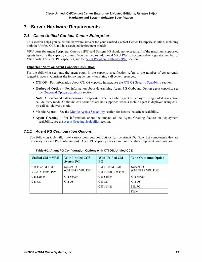
7.1.1 Agent PG Configuration Options
The following tables illustrate various configuration options for the Agent PG (they list components that are
necessary for each PG configuration). Agent PG capacity varies based on specific component configuration.
Table 6-1: Agent PG Configuration Options with CTI OS, Unified CCE
Unified CM + VRU With Unified CCE
System PG
With Unified CM
PG
With Outbound Option
CM PG (CM PIM) System PG
(CM PIM + VRU PIM)
CM PG (CM PIM) System PG
(CM PIM + VRU PIM) VRU PG (VRU PIM) CM PG (2) (CM PIM)
CTI Server CTI Server CTI Server CTI Server
CTI OS CTI OS CTI OS CTI OS
CTI OS (2) MR PG
Dialer

Cisco Unified ICM/Contact Center Enterprise & Hosted Editions, Release 9.0(x)
Hardware and System Software Specification
© 2008 – 2014 Cisco Systems, Inc. 20
Table 6-2: Agent PG Configuration Options with Cisco Agent Desktop, Unified CCE
Unified CM + VRU With Unified CCE
System PG
With Unified
Communications
Manager PG
With Outbound Option
CM PG (CM PIM) System PG
(CM PIM + VRU PIM)
CM PG (CM PIM) System PG
(CM PIM + VRU PIM) VRU PG (VRU PIM)
CTI Server CTI Server CTI Server CTI Server
CTI OS CTI OS CTI OS CTI OS
MR PG
Dialer
CAD Services CAD Services CAD Services CAD Services
Table 6-3: Agent PG Configuration Options with Cisco Finesse, Unified CCE
Unified CM + VRU With Unified Communications
Manager PG
With Outbound Option
CM PG (CM PIM) CM PG (CM PIM) System PG (CM PIM + VRU PIM)
VRU PG (VRU PIM) CTI Server
CTI Server CTI Server MR PG
Dialer
7.1.2 New Deployments and Technology Refresh
Note: The capacities that are listed in this section assume that each agent is handling 30 calls per hour.
7.1.2.1 Option 1: Supports up to 450 Agents
Progger Configuration: The Progger configuration consists of Unified CCE Router, Unified CCE Logger,
Agent PG (Unified CM PIM, VRU PIM, CG, CTI OS, and CAD Services when CAD is required) on the same
server.
Note: You can also install the Outbound Option on the Progger; however, the number of agents supported will
be reduced. For more details, see the Outbound Option Scalability section.
Table 6-4: Progger Servers, Unified CCE, New Deployments and Technology Refresh
Server Class Capacity (Agents)
Progger with CTI OS Progger with CAD
Services
MCS-30-005-Class 100 —
MCS-40-011-Class 450 297
For Progger configuration, select Unified CCE 450 Agents Progger deployment type. Override the CPS
capacity using congestion settings when the hardware configuration is lower than the capacity of MCS-40-011
class servers.
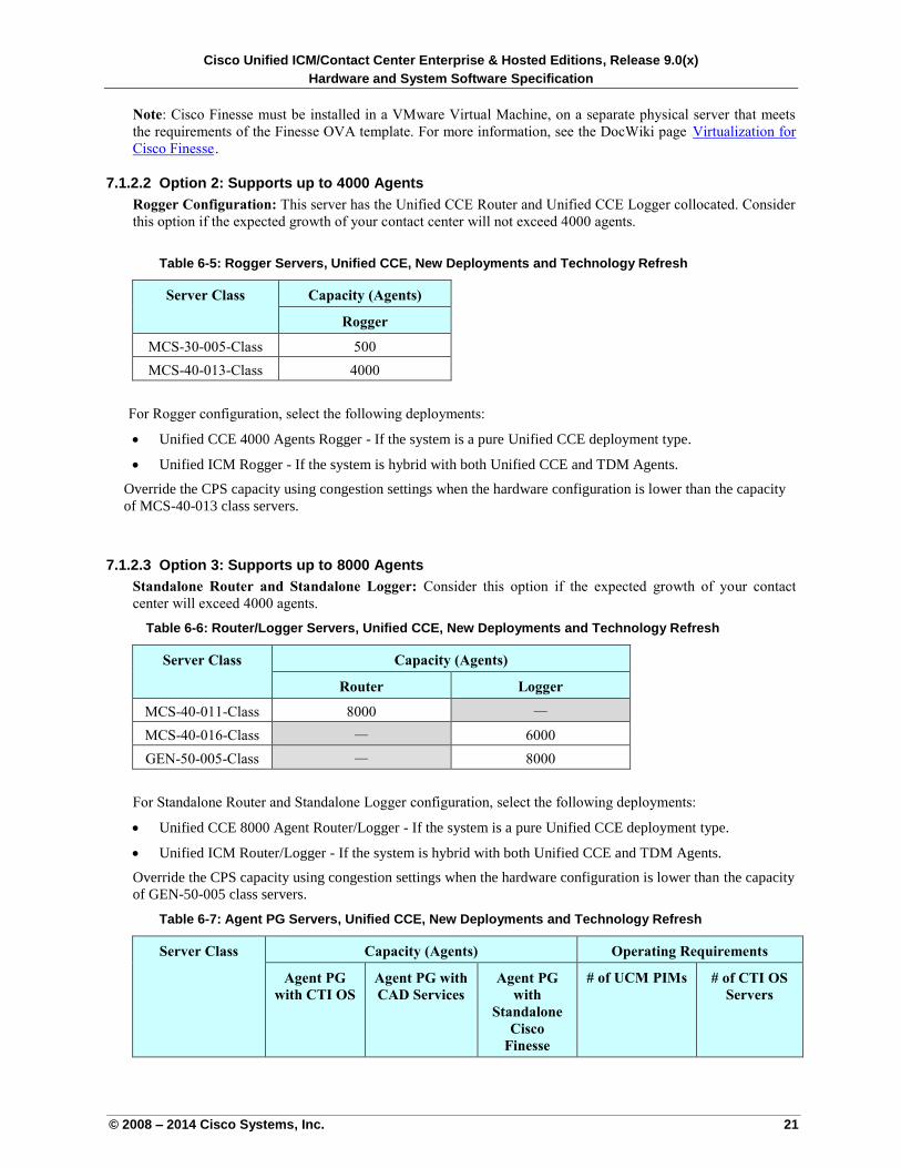
Cisco Unified ICM/Contact Center Enterprise & Hosted Editions, Release 9.0(x)
Hardware and System Software Specification
© 2008 – 2014 Cisco Systems, Inc. 21
Note: Cisco Finesse must be installed in a VMware Virtual Machine, on a separate physical server that meets
the requirements of the Finesse OVA template. For more information, see the DocWiki page UVirtualization for
Cisco FinesseU.
7.1.2.2 Option 2: Supports up to 4000 Agents
Rogger Configuration: This server has the Unified CCE Router and Unified CCE Logger collocated. Consider
this option if the expected growth of your contact center will not exceed 4000 agents.
Table 6-5: Rogger Servers, Unified CCE, New Deployments and Technology Refresh
Server Class Capacity (Agents)
Rogger
MCS-30-005-Class 500
MCS-40-013-Class 4000
For Rogger configuration, select the following deployments:
Unified CCE 4000 Agents Rogger - If the system is a pure Unified CCE deployment type.
Unified ICM Rogger - If the system is hybrid with both Unified CCE and TDM Agents.
Override the CPS capacity using congestion settings when the hardware configuration is lower than the capacity
of MCS-40-013 class servers.
7.1.2.3 Option 3: Supports up to 8000 Agents
Standalone Router and Standalone Logger: Consider this option if the expected growth of your contact
center will exceed 4000 agents.
Table 6-6: Router/Logger Servers, Unified CCE, New Deployments and Technology Refresh
Server Class Capacity (Agents)
Router Logger
MCS-40-011-Class 8000 —
MCS-40-016-Class — 6000
GEN-50-005-Class — 8000
For Standalone Router and Standalone Logger configuration, select the following deployments:
Unified CCE 8000 Agent Router/Logger - If the system is a pure Unified CCE deployment type.
Unified ICM Router/Logger - If the system is hybrid with both Unified CCE and TDM Agents.
Override the CPS capacity using congestion settings when the hardware configuration is lower than the capacity
of GEN-50-005 class servers.
Table 6-7: Agent PG Servers, Unified CCE, New Deployments and Technology Refresh
Server Class Capacity (Agents) Operating Requirements
Agent PG
with CTI OS
Agent PG with
CAD Services
Agent PG
with
Standalone
Cisco
Finesse
# of UCM PIMs # of CTI OS
Servers
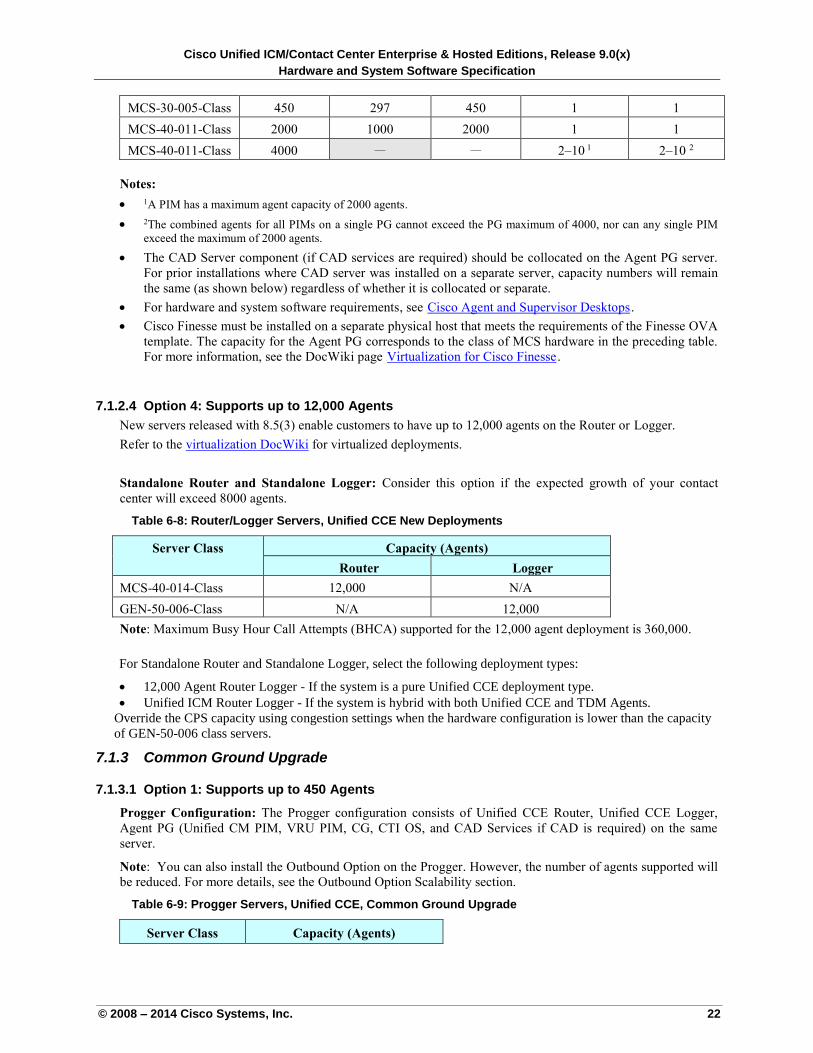
Cisco Unified ICM/Contact Center Enterprise & Hosted Editions, Release 9.0(x)
Hardware and System Software Specification
© 2008 – 2014 Cisco Systems, Inc. 22
MCS-30-005-Class 450 297 450 1 1
MCS-40-011-Class 2000 1000 2000 1 1
MCS-40-011-Class 4000 — — 2–10 1 2–10 2
Notes:
1A PIM has a maximum agent capacity of 2000 agents.
2The combined agents for all PIMs on a single PG cannot exceed the PG maximum of 4000, nor can any single PIM
exceed the maximum of 2000 agents.
The CAD Server component (if CAD services are required) should be collocated on the Agent PG server.
For prior installations where CAD server was installed on a separate server, capacity numbers will remain
the same (as shown below) regardless of whether it is collocated or separate.
For hardware and system software requirements, see UCisco Agent and Supervisor DesktopsU.
Cisco Finesse must be installed on a separate physical host that meets the requirements of the Finesse OVA
template. The capacity for the Agent PG corresponds to the class of MCS hardware in the preceding table.
For more information, see the DocWiki page UVirtualization for Cisco FinesseU.
7.1.2.4 Option 4: Supports up to 12,000 Agents
New servers released with 8.5(3) enable customers to have up to 12,000 agents on the Router or Logger.
Refer to the virtualization DocWiki for virtualized deployments.
Standalone Router and Standalone Logger: Consider this option if the expected growth of your contact
center will exceed 8000 agents.
Table 6-8: Router/Logger Servers, Unified CCE New Deployments
Server Class Capacity (Agents)
Router Logger
MCS-40-014-Class 12,000 N/A
GEN-50-006-Class N/A 12,000
Note: Maximum Busy Hour Call Attempts (BHCA) supported for the 12,000 agent deployment is 360,000.
For Standalone Router and Standalone Logger, select the following deployment types:
12,000 Agent Router Logger - If the system is a pure Unified CCE deployment type.
Unified ICM Router Logger - If the system is hybrid with both Unified CCE and TDM Agents.
Override the CPS capacity using congestion settings when the hardware configuration is lower than the capacity
of GEN-50-006 class servers.
7.1.3 Common Ground Upgrade
7.1.3.1 Option 1: Supports up to 450 Agents
Progger Configuration: The Progger configuration consists of Unified CCE Router, Unified CCE Logger,
Agent PG (Unified CM PIM, VRU PIM, CG, CTI OS, and CAD Services if CAD is required) on the same
server.
Note: You can also install the Outbound Option on the Progger. However, the number of agents supported will
be reduced. For more details, see the Outbound Option Scalability section.
Table 6-9: Progger Servers, Unified CCE, Common Ground Upgrade
Server Class Capacity (Agents)
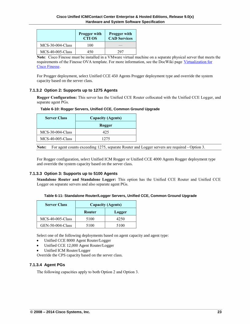
Cisco Unified ICM/Contact Center Enterprise & Hosted Editions, Release 9.0(x)
Hardware and System Software Specification
© 2008 – 2014 Cisco Systems, Inc. 23
Progger with
CTI OS
Progger with
CAD Services
MCS-30-004-Class 100 —
MCS-40-005-Class 450 297
Note: Cisco Finesse must be installed in a VMware virtual machine on a separate physical server that meets the
requirements of the Finesse OVA template. For more information, see the DocWiki page UVirtualization for
Cisco FinesseU.
For Progger deployment, select Unified CCE 450 Agents Progger deployment type and override the system
capacity based on the server class.
7.1.3.2 Option 2: Supports up to 1275 Agents
Rogger Configuration: This server has the Unified CCE Router collocated with the Unified CCE Logger, and
separate agent PGs.
Table 6-10: Rogger Servers, Unified CCE, Common Ground Upgrade
Server Class Capacity (Agents)
Rogger
MCS-30-004-Class 425
MCS-40-005-Class 1275
Note: For agent counts exceeding 1275, separate Router and Logger servers are required - Option 3.
For Rogger configuration, select Unified ICM Rogger or Unified CCE 4000 Agents Rogger deployment type
and override the system capacity based on the server class.
7.1.3.3 Option 3: Supports up to 5100 Agents
Standalone Router and Standalone Logger: This option has the Unified CCE Router and Unified CCE
Logger on separate servers and also separate agent PGs.
Table 6-11: Standalone Router/Logger Servers, Unified CCE, Common Ground Upgrade
Server Class Capacity (Agents)
Router Logger
MCS-40-005-Class 5100 4250
GEN-50-004-Class 5100 5100
Select one of the following deployments based on agent capacity and agent type:
Unified CCE 8000 Agent Router/Logger
Unified CCE 12,000 Agent Router/Logger
Unified ICM Router/Logger
Override the CPS capacity based on the server class.
7.1.3.4 Agent PGs
The following capacities apply to both Option 2 and Option 3.
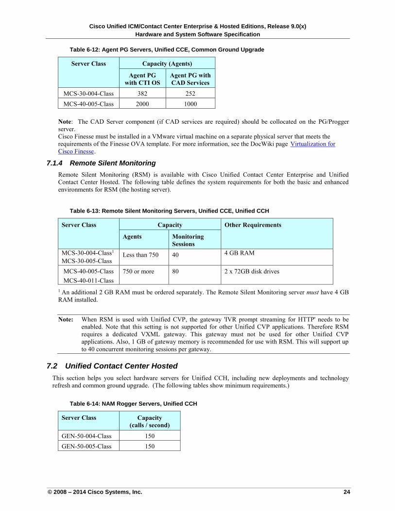
Cisco Unified ICM/Contact Center Enterprise & Hosted Editions, Release 9.0(x)
Hardware and System Software Specification
© 2008 – 2014 Cisco Systems, Inc. 24
Table 6-12: Agent PG Servers, Unified CCE, Common Ground Upgrade
Server Class Capacity (Agents)
Agent PG
with CTI OS
Agent PG with
CAD Services
MCS-30-004-Class 382 252
MCS-40-005-Class 2000 1000
Note: The CAD Server component (if CAD services are required) should be collocated on the PG/Progger
server.
Cisco Finesse must be installed in a VMware virtual machine on a separate physical server that meets the
requirements of the Finesse OVA template. For more information, see the DocWiki page UVirtualization for
Cisco FinesseU.
7.1.4 Remote Silent Monitoring
Remote Silent Monitoring (RSM) is available with Cisco Unified Contact Center Enterprise and Unified
Contact Center Hosted. The following table defines the system requirements for both the basic and enhanced
environments for RSM (the hosting server).
Table 6-13: Remote Silent Monitoring Servers, Unified CCE, Unified CCH
Server Class Capacity Other Requirements
Agents Monitoring
Sessions
MCS-30-004-Class1
MCS-30-005-Class Less than 750 40 4 GB RAM
MCS-40-005-Class
MCS-40-011-Class
750 or more 80 2 x 72GB disk drives
1 An additional 2 GB RAM must be ordered separately. The Remote Silent Monitoring server must have 4 GB
RAM installed.
Note: When RSM is used with Unified CVP, the gateway 'IVR prompt streaming for HTTP' needs to be
enabled. Note that this setting is not supported for other Unified CVP applications. Therefore RSM
requires a dedicated VXML gateway. This gateway must not be used for other Unified CVP
applications. Also, 1 GB of gateway memory is recommended for use with RSM. This will support up
to 40 concurrent monitoring sessions per gateway.
7.2 Unified Contact Center Hosted
This section helps you select hardware servers for Unified CCH, including new deployments and technology
refresh and common ground upgrade. (The following tables show minimum requirements.)
Table 6-14: NAM Rogger Servers, Unified CCH
Server Class Capacity
(calls / second)
GEN-50-004-Class 150
GEN-50-005-Class 150
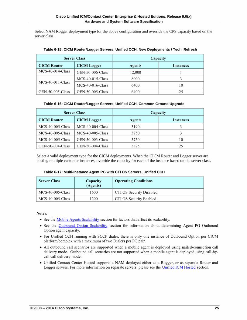
Cisco Unified ICM/Contact Center Enterprise & Hosted Editions, Release 9.0(x)
Hardware and System Software Specification
© 2008 – 2014 Cisco Systems, Inc. 25
Select NAM Rogger deployment type for the above configuration and override the CPS capacity based on the
server class.
Table 6-15: CICM Router/Logger Servers, Unified CCH, New Deployments / Tech. Refresh
Server Class Capacity
CICM Router CICM Logger Agents Instances
MCS-40-014-Class GEN-50-006-Class 12,000 1
MCS-40-011-Class MCS-40-015-Class 8000 3
MCS-40-016-Class 6400 10
GEN-50-005-Class GEN-50-005-Class 6400 25
Table 6-16: CICM Router/Logger Servers, Unified CCH, Common Ground Upgrade
Server Class Capacity
CICM Router CICM Logger Agents Instances
MCS-40-005-Class MCS-40-004-Class 3190 3
MCS-40-005-Class MCS-40-005-Class 3750 3
MCS-40-005-Class GEN-50-003-Class 3750 10
GEN-50-004-Class GEN-50-004-Class 3825 25
Select a valid deployment type for the CICM deployments. When the CICM Router and Logger server are
hosting multiple customer instances, override the capacity for each of the instance based on the server class.
Table 6-17: Multi-Instance Agent PG with CTI OS Servers, Unified CCH
Server Class Capacity
(Agents)
Operating Conditions
MCS-40-005-Class 1600 CTI OS Security Disabled
MCS-40-005-Class 1200 CTI OS Security Enabled
Notes:
See the UMobile Agents ScalabilityU section for factors that affect its scalability.
See the UOutbound Option ScalabilityU section for information about determining Agent PG Outbound
Option agent capacity.
For Unified CCH running with SCCP dialer, there is only one instance of Outbound Option per CICM
platform/complex with a maximum of two Dialers per PG pair.
All outbound call scenarios are supported when a mobile agent is deployed using nailed-connection call
delivery mode. Outbound call scenarios are not supported when a mobile agent is deployed using call-by-
call call delivery mode.
Unified Contact Center Hosted supports a NAM deployed either as a Rogger, or as separate Router and
Logger servers. For more information on separate servers, please see the UUnified ICM HostedU section.
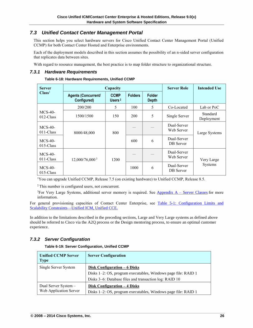
Cisco Unified ICM/Contact Center Enterprise & Hosted Editions, Release 9.0(x)
Hardware and System Software Specification
© 2008 – 2014 Cisco Systems, Inc. 26
7.3 Unified Contact Center Management Portal
This section helps you select hardware servers for Cisco Unified Contact Center Management Portal (Unified
CCMP) for both Contact Center Hosted and Enterprise environments.
Each of the deployment models described in this section assumes the possibility of an n-sided server configuration
that replicates data between sites.
With regard to resource management, the best practice is to map folder structure to organizational structure.
7.3.1 Hardware Requirements
Table 6-18: Hardware Requirements, Unified CCMP
Server
Class1
Capacity Server Role Intended Use
Agents (Concurrent/ Configured)
CCMP Users 2
Folders Folder Depth
MCS-40-
012-Class
200/200 5 100 5 Co-Located Lab or PoC
1500/1500 150 200 5 Single Server Standard
Deployment
MCS-40-
011-Class 8000/48,000 800
— — Dual-Server
Web Server Large Systems
MCS-40-
015-Class
600 6 Dual-Server
DB Server
MCS-40-
011-Class 12,000/76,000 3 1200
— — Dual-Server
Web Server Very Large
Systems MCS-40-
015-Class
1000 6 Dual-Server
DB Server
1You can upgrade Unified CCMP, Release 7.5 (on existing hardware) to Unified CCMP, Release 8.5.
2 This number is configured users, not concurrent. 3For Very Large Systems, additional server memory is required. See Appendix A – Server Classes Ufor more
information.
For general provisioning capacities of Contact Center Enterprise, see Table 5-1: Configuration Limits and
Scalability Constraints—Unified ICM, Unified CCE.
In addition to the limitations described in the preceding sections, Large and Very Large systems as defined above
should be referred to Cisco via the A2Q process or the Design mentoring process, to ensure an optimal customer
experience.
7.3.2 Server Configuration
Table 6-19: Server Configuration, Unified CCMP
Unified CCMP Server
Type
Server Configuration
Single Server System UDisk Configuration – 6 Disks
Disks 1–2: OS, program executables, Windows page file: RAID 1
Disks 3–6: Database files and transaction log: RAID 10
Dual Server System –
Web Application Server UDisk Configuration – 4 Disks
Disks 1–2: OS, program executables, Windows page file: RAID 1
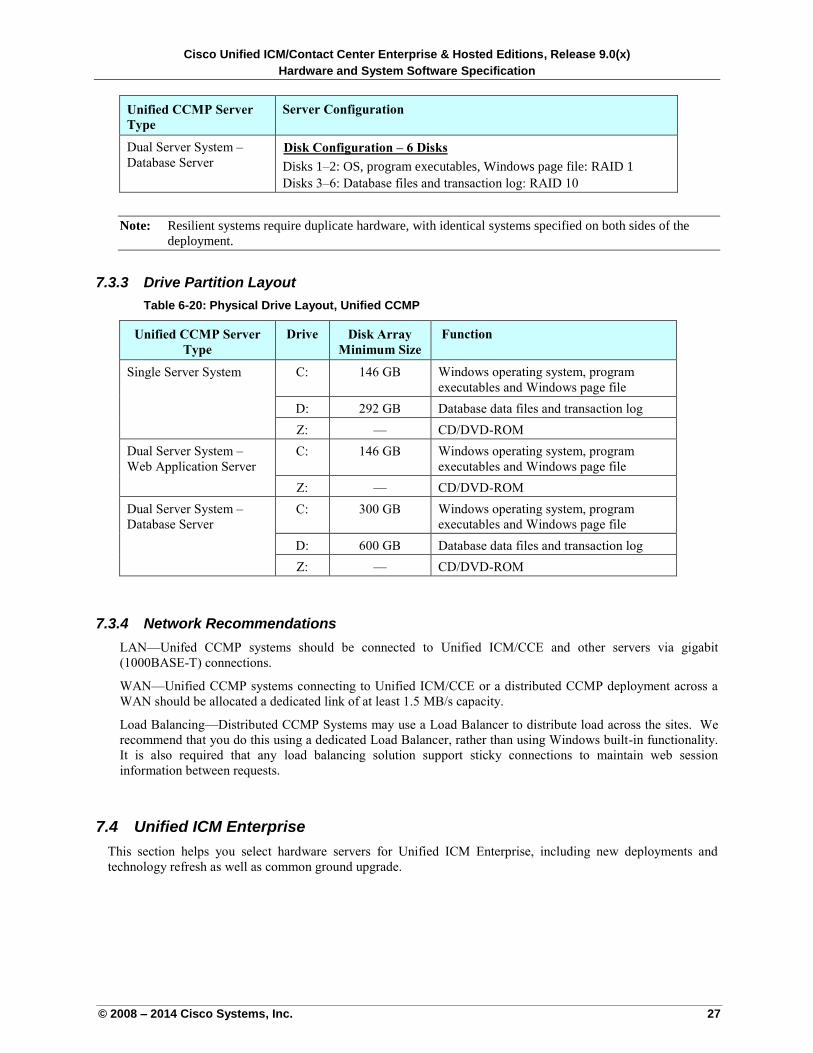
Cisco Unified ICM/Contact Center Enterprise & Hosted Editions, Release 9.0(x)
Hardware and System Software Specification
© 2008 – 2014 Cisco Systems, Inc. 27
Unified CCMP Server
Type
Server Configuration
Dual Server System –
Database Server UDisk Configuration – 6 Disks
Disks 1–2: OS, program executables, Windows page file: RAID 1
Disks 3–6: Database files and transaction log: RAID 10
Note: Resilient systems require duplicate hardware, with identical systems specified on both sides of the
deployment.
7.3.3 Drive Partition Layout
Table 6-20: Physical Drive Layout, Unified CCMP
Unified CCMP Server
Type
Drive Disk Array
Minimum Size
Function
Single Server System C: 146 GB Windows operating system, program
executables and Windows page file
D: 292 GB Database data files and transaction log
Z: — CD/DVD-ROM
Dual Server System –
Web Application Server
C: 146 GB Windows operating system, program
executables and Windows page file
Z: — CD/DVD-ROM
Dual Server System –
Database Server
C: 300 GB Windows operating system, program
executables and Windows page file
D: 600 GB Database data files and transaction log
Z: — CD/DVD-ROM
7.3.4 Network Recommendations
LAN—Unifed CCMP systems should be connected to Unified ICM/CCE and other servers via gigabit
(1000BASE-T) connections.
WAN—Unified CCMP systems connecting to Unified ICM/CCE or a distributed CCMP deployment across a
WAN should be allocated a dedicated link of at least 1.5 MB/s capacity.
Load Balancing—Distributed CCMP Systems may use a Load Balancer to distribute load across the sites. We
recommend that you do this using a dedicated Load Balancer, rather than using Windows built-in functionality.
It is also required that any load balancing solution support sticky connections to maintain web session
information between requests.
7.4 Unified ICM Enterprise
This section helps you select hardware servers for Unified ICM Enterprise, including new deployments and
technology refresh as well as common ground upgrade.
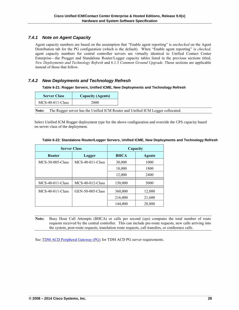
Cisco Unified ICM/Contact Center Enterprise & Hosted Editions, Release 9.0(x)
Hardware and System Software Specification
© 2008 – 2014 Cisco Systems, Inc. 28
7.4.1 Note on Agent Capacity
Agent capacity numbers are based on the assumption that “Enable agent reporting” is unchecked on the Agent
Distribution tab for the PG configuration (which is the default). When “Enable agent reporting” is checked,
agent capacity numbers for central controller servers are virtually identical to Unified Contact Center
Enterprise—the Progger and Standalone Router/Logger capacity tables listed in the previous sections titled,
New Deployments and Technology Refresh and 6.1.3 Common Ground Upgrade. Those sections are applicable
instead of those that follow.
7.4.2 New Deployments and Technology Refresh
Table 6-21: Rogger Servers, Unified ICME, New Deployments and Technology Refresh
Server Class Capacity (Agents)
MCS-40-011-Class 2000
Note: The Rogger server has the Unified ICM Router and Unified ICM Logger collocated.
Select Unified ICM Rogger deployment type for the above configuration and override the CPS capacity based
on server class of the deployment.
Table 6-22: Standalone Router/Logger Servers, Unified ICME, New Deployments and Technology Refresh
Server Class Capacity
Router Logger BHCA Agents
MCS-30-005-Class MCS-40-011-Class 30,000 1000
18,000 1800
12,000 2400
MCS-40-011-Class MCS-40-012-Class 150,000 5000
MCS-40-011-Class GEN-50-005-Class 360,000 12,000
216,000 21,600
144,000 28,800
Note: Busy Hour Call Attempts (BHCA) or calls per second (cps) computes the total number of route
requests received by the central controller. This can include pre-route requests, new calls arriving into
the system, post-route requests, translation route requests, call transfers, or conference calls.
See UTDM ACD Peripheral Gateway (PG) U for TDM ACD PG server requirements.
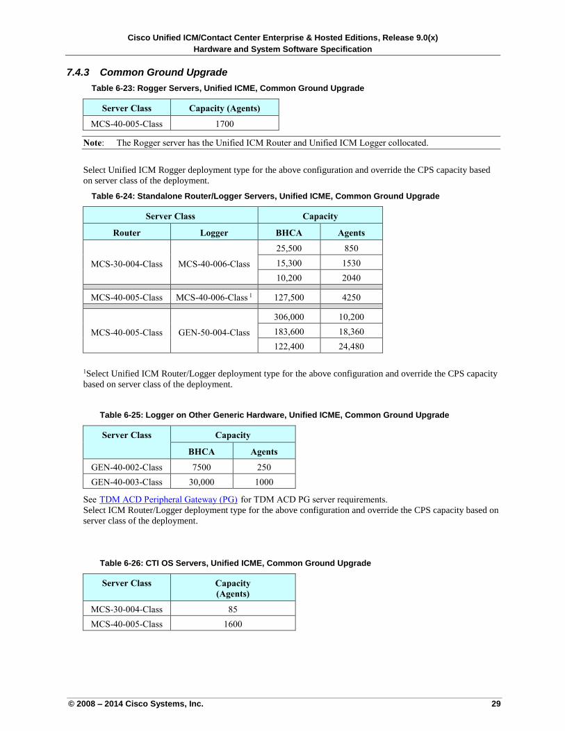
Cisco Unified ICM/Contact Center Enterprise & Hosted Editions, Release 9.0(x)
Hardware and System Software Specification
© 2008 – 2014 Cisco Systems, Inc. 29
7.4.3 Common Ground Upgrade
Table 6-23: Rogger Servers, Unified ICME, Common Ground Upgrade
Server Class Capacity (Agents)
MCS-40-005-Class 1700
Note: The Rogger server has the Unified ICM Router and Unified ICM Logger collocated.
Select Unified ICM Rogger deployment type for the above configuration and override the CPS capacity based
on server class of the deployment.
Table 6-24: Standalone Router/Logger Servers, Unified ICME, Common Ground Upgrade
Server Class Capacity
Router Logger BHCA Agents
MCS-30-004-Class MCS-40-006-Class
25,500 850
15,300 1530
10,200 2040
MCS-40-005-Class MCS-40-006-Class 1 127,500 4250
MCS-40-005-Class GEN-50-004-Class
306,000 10,200
183,600 18,360
122,400 24,480
1Select Unified ICM Router/Logger deployment type for the above configuration and override the CPS capacity
based on server class of the deployment.
Table 6-25: Logger on Other Generic Hardware, Unified ICME, Common Ground Upgrade
Server Class Capacity
BHCA Agents
GEN-40-002-Class 7500 250
GEN-40-003-Class 30,000 1000
See UTDM ACD Peripheral Gateway (PG) U for TDM ACD PG server requirements.
Select ICM Router/Logger deployment type for the above configuration and override the CPS capacity based on
server class of the deployment.
Table 6-26: CTI OS Servers, Unified ICME, Common Ground Upgrade
Server Class Capacity
(Agents)
MCS-30-004-Class 85
MCS-40-005-Class 1600
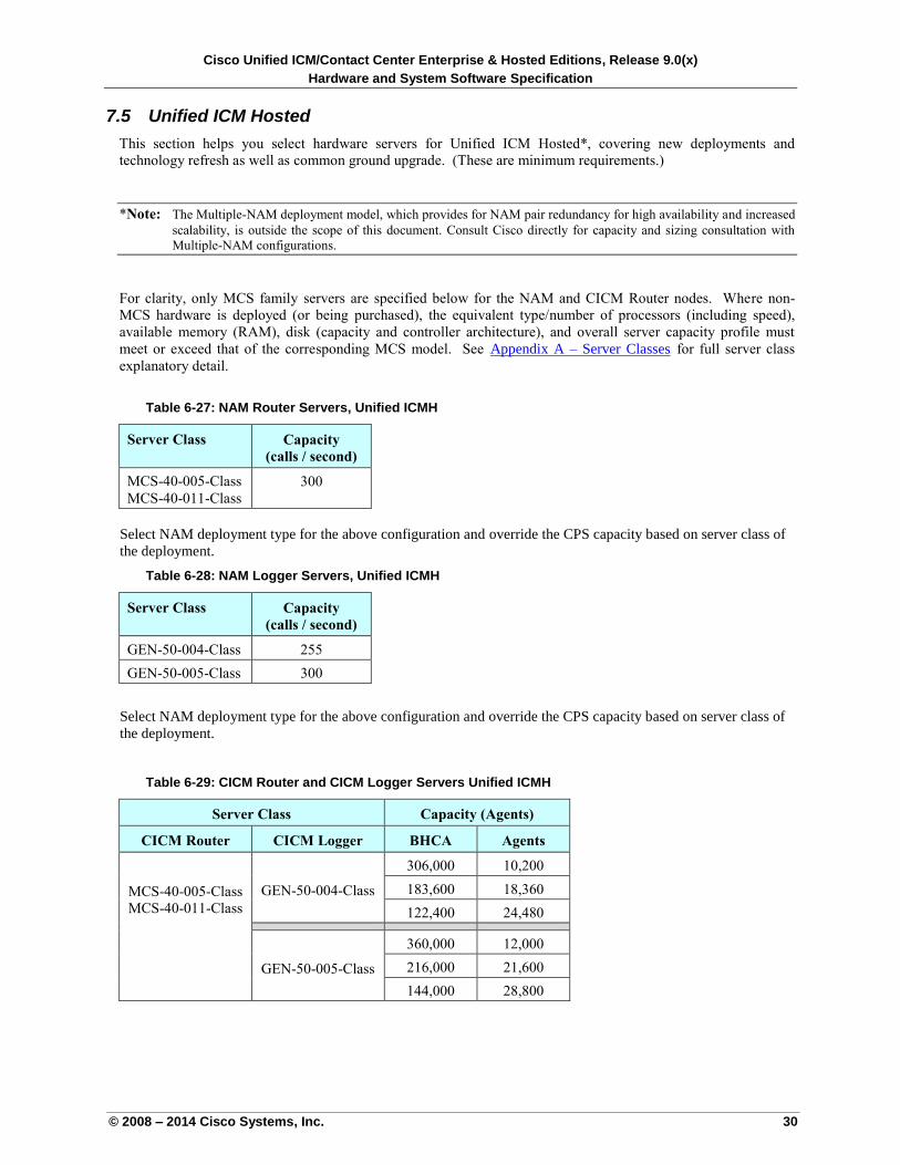
Cisco Unified ICM/Contact Center Enterprise & Hosted Editions, Release 9.0(x)
Hardware and System Software Specification
© 2008 – 2014 Cisco Systems, Inc. 30
7.5 Unified ICM Hosted
This section helps you select hardware servers for Unified ICM Hosted*, covering new deployments and
technology refresh as well as common ground upgrade. (These are minimum requirements.)
*Note: The Multiple-NAM deployment model, which provides for NAM pair redundancy for high availability and increased
scalability, is outside the scope of this document. Consult Cisco directly for capacity and sizing consultation with
Multiple-NAM configurations.
For clarity, only MCS family servers are specified below for the NAM and CICM Router nodes. Where non-
MCS hardware is deployed (or being purchased), the equivalent type/number of processors (including speed),
available memory (RAM), disk (capacity and controller architecture), and overall server capacity profile must
meet or exceed that of the corresponding MCS model. See UAppendix A – Server ClassesU for full server class
explanatory detail.
Table 6-27: NAM Router Servers, Unified ICMH
Server Class Capacity
(calls / second)
MCS-40-005-Class
MCS-40-011-Class
300
Select NAM deployment type for the above configuration and override the CPS capacity based on server class of
the deployment.
Table 6-28: NAM Logger Servers, Unified ICMH
Server Class Capacity
(calls / second)
GEN-50-004-Class 255
GEN-50-005-Class 300
Select NAM deployment type for the above configuration and override the CPS capacity based on server class of
the deployment.
Table 6-29: CICM Router and CICM Logger Servers Unified ICMH
Server Class Capacity (Agents)
CICM Router CICM Logger BHCA Agents
MCS-40-005-Class
MCS-40-011-Class
GEN-50-004-Class
306,000 10,200
183,600 18,360
122,400 24,480
GEN-50-005-Class
360,000 12,000
216,000 21,600
144,000 28,800
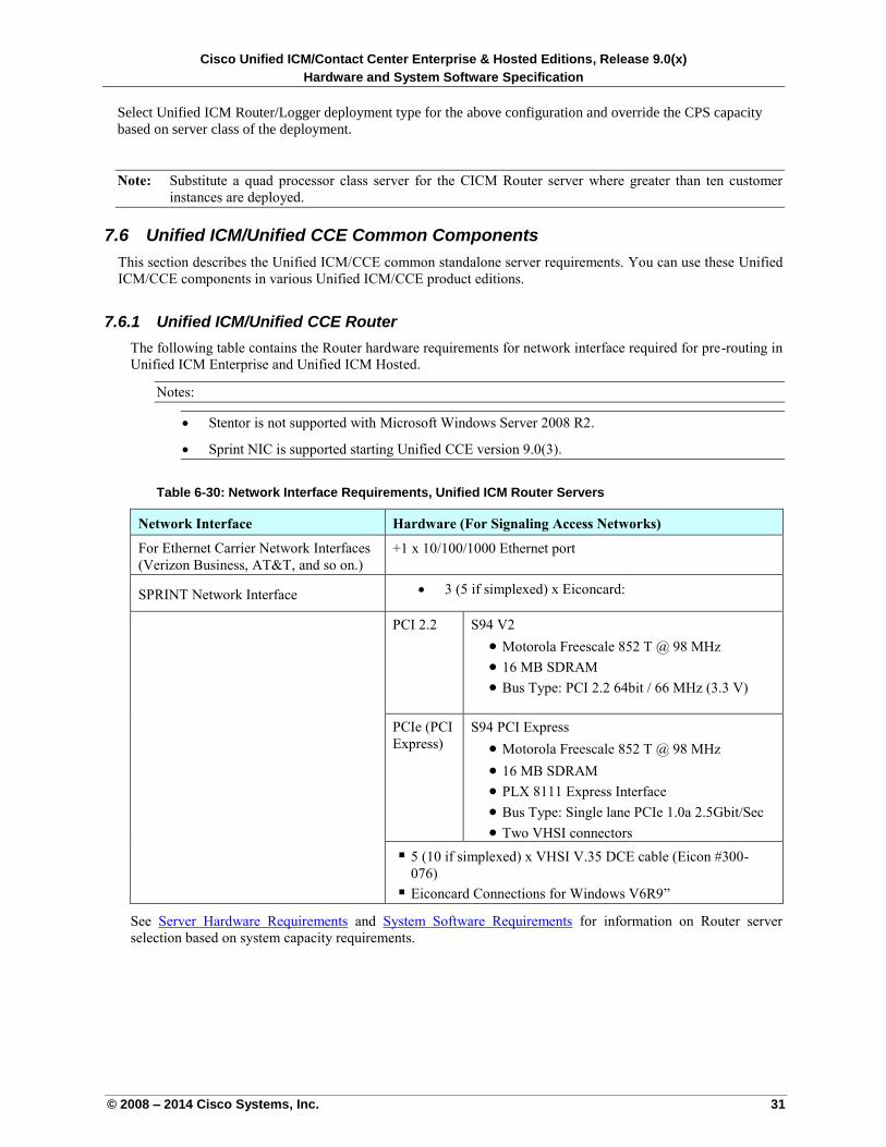
Cisco Unified ICM/Contact Center Enterprise & Hosted Editions, Release 9.0(x)
Hardware and System Software Specification
© 2008 – 2014 Cisco Systems, Inc. 31
Select Unified ICM Router/Logger deployment type for the above configuration and override the CPS capacity
based on server class of the deployment.
Note: Substitute a quad processor class server for the CICM Router server where greater than ten customer
instances are deployed.
7.6 Unified ICM/Unified CCE Common Components
This section describes the Unified ICM/CCE common standalone server requirements. You can use these Unified
ICM/CCE components in various Unified ICM/CCE product editions.
7.6.1 Unified ICM/Unified CCE Router
The following table contains the Router hardware requirements for network interface required for pre-routing in
Unified ICM Enterprise and Unified ICM Hosted.
Notes:
Stentor is not supported with Microsoft Windows Server 2008 R2.
Sprint NIC is supported starting Unified CCE version 9.0(3).
Table 6-30: Network Interface Requirements, Unified ICM Router Servers
Network Interface Hardware (For Signaling Access Networks)
For Ethernet Carrier Network Interfaces
(Verizon Business, AT&T, and so on.)
+1 x 10/100/1000 Ethernet port
SPRINT Network Interface 3 (5 if simplexed) x Eiconcard:
PCI 2.2 S94 V2
Motorola Freescale 852 T @ 98 MHz
16 MB SDRAM
Bus Type: PCI 2.2 64bit / 66 MHz (3.3 V)
PCIe (PCI
Express)
S94 PCI Express
Motorola Freescale 852 T @ 98 MHz
16 MB SDRAM
PLX 8111 Express Interface
Bus Type: Single lane PCIe 1.0a 2.5Gbit/Sec
Two VHSI connectors
5 (10 if simplexed) x VHSI V.35 DCE cable (Eicon #300-
076)
Eiconcard Connections for Windows V6R9”
See Server Hardware Requirements and System Software Requirements for information on Router server
selection based on system capacity requirements.
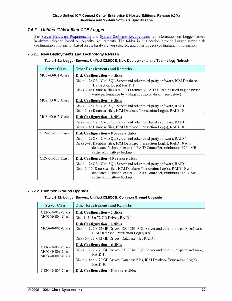
Cisco Unified ICM/Contact Center Enterprise & Hosted Editions, Release 9.0(x)
Hardware and System Software Specification
© 2008 – 2014 Cisco Systems, Inc. 32
7.6.2 Unified ICM/Unified CCE Logger
See Server Hardware Requirements and System Software Requirements for information on Logger server
hardware selection based on capacity requirements. The tables in this section provide Logger server disk
configuration information based on the hardware you selected, and other Logger configuration information.
7.6.2.1 New Deployments and Technology Refresh
Table 6-31: Logger Servers, Unified ICM/CCE, New Deployments and Technology Refresh
Server Class Other Requirements and Remarks
MCS-40-011-Class
UDisk Configuration – 4 disks
Disks 1–2: OS, ICM, SQL Server and other third-party software, ICM Database
Transaction Log(s) RAID 1
Disks 3–4: Database files RAID 1 (alternately RAID 10 can be used to gain better
write performance by adding additional disks – see below)
MCS-40-012-Class UDisk Configuration – 6 disks
Disks 1–2: OS, ICM, SQL Server and other third-party software, RAID 1
Disks 3–6: Database files, ICM Database Transaction Log(s), RAID 10
MCS-40-013-Class UDisk Configuration – 8 disks
Disks 1–2: OS, ICM, SQL Server and other third-party software, RAID 1
Disks 3–8: Database files, ICM Database Transaction Log(s), RAID 10
GEN-50-005-Class UDisk Configuration – 8 or more disks
Disks 1–2: OS, ICM, SQL Server and other third-party software, RAID 1
Disks 3–8: Database files, ICM Database Transaction Log(s), RAID 10 with
dedicated 2 channel external RAID Controller, minimum of 256 MB
cache with battery backup
GEN-50-006-Class UDisk Configuration –10 or more disks
Disks 1–2: OS, ICM, SQL Server and other third-party software, RAID 1
Disks 3–10: Database files, ICM Database Transaction Log(s), RAID 10 with
dedicated 2 channel external RAID Controller, minimum of 512 MB
cache with battery backup
7.6.2.2 Common Ground Upgrade
Table 6-32: Logger Servers, Unified ICM/CCE, Common Ground Upgrade
Server Class Other Requirements and Remarks
GEN-30-002-Class
MCS-30-004-Class UDisk Configuration – 2 disks
Disk 1–2: 2 x 72 GB Drives, RAID 1
MCS-40-005-Class
UDisk Configuration – 4 disks
Disks 1–2: 2 x 72 GB Drives: OS, ICM, SQL Server and other third-party software,
ICM Database Transaction Log(s) RAID 1
Disks 3–4: 2 x 72 GB Drives: Database files RAID 1
GEN-40-003-Class
MCS-40-006-Class
MCS-40-009-Class
UDisk Configuration – 6 disks
Disks 1–2: 2 x 72 GB Drives: OS, ICM, SQL Server and other third-party software,
RAID 1
Disks 3–6: 4 x 72 GB Drives: Database files, ICM Database Transaction Log(s),
RAID 10
GEN-40-003-Class UDisk Configuration – 8 or more disks
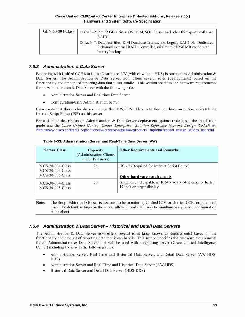
Cisco Unified ICM/Contact Center Enterprise & Hosted Editions, Release 9.0(x)
Hardware and System Software Specification
© 2008 – 2014 Cisco Systems, Inc. 33
GEN-50-004-Class
Disks 1–2: 2 x 72 GB Drives: OS, ICM, SQL Server and other third-party software,
RAID 1
Disks 3–*: Database files, ICM Database Transaction Log(s), RAID 10. Dedicated
2 channel external RAID Controller, minimum of 256 MB cache with
battery backup
7.6.3 Administration & Data Server
Beginning with Unified CCE 8.0(1), the Distributor AW (with or without HDS) is renamed as Administration &
Data Server. The Administration & Data Server now offers several roles (deployments) based on the
functionality and amount of reporting data that it can handle. This section specifies the hardware requirements
for an Administration & Data Server with the following roles:
Administration Server and Real-time Data Server
Configuration-Only Administration Server
Please note that these roles do not include the HDS/DDS. Also, note that you have an option to install the
Internet Script Editor (ISE) on this server.
For a detailed description on Administration & Data Server deployment options (roles), see the installation
guide and the Cisco Unified Contact Center Enterprise Solution Reference Network Design (SRND) at:
Uhttp://www.cisco.com/en/US/products/sw/custcosw/ps1844/products_implementation_design_guides_list.html U
Table 6-33: Administration Server and Real-Time Data Server (AW)
Server Class Capacity
(Administration Clients
and/or ISE users)
Other Requirements and Remarks
MCS-20-004-Class
MCS-20-005-Class
MCS-20-006-Class
25 IIS 7.5 (Required for Internet Script Editor)
UOther hardware requirements
Graphics card capable of 1024 x 768 x 64 K color or better
17 inch or larger display MCS-30-004-Class
MCS-30-005-Class
50
Note: The Script Editor or ISE user is assumed to be monitoring Unified ICM or Unified CCE scripts in real
time. The default settings on the server allow for only 10 users to simultaneously reload configuration
at the client.
7.6.4 Administration & Data Server – Historical and Detail Data Servers
The Administration & Data Server now offers several roles (also known as deployments) based on the
functionality and amount of reporting data that it can handle. This section specifies the hardware requirements
for an Administration & Data Server that will be used with a reporting server (Cisco Unified Intelligence
Center) including those with the following roles:
Administration Server, Real-Time and Historical Data Server, and Detail Data Server (AW-HDS-
DDS)
Administration Server and Real-Time and Historical Data Server (AW-HDS)
Historical Data Server and Detail Data Server (HDS-DDS)
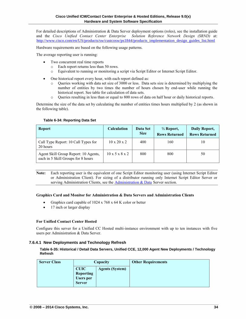
Cisco Unified ICM/Contact Center Enterprise & Hosted Editions, Release 9.0(x)
Hardware and System Software Specification
© 2008 – 2014 Cisco Systems, Inc. 34
For detailed descriptions of Administration & Data Server deployment options (roles), see the installation guide
and the Cisco Unified Contact Center Enterprise Solution Reference Network Design (SRND) at:
Uhttp://www.cisco.com/en/US/products/sw/custcosw/ps1844/products_implementation_design_guides_list.html U
Hardware requirements are based on the following usage patterns.
The average reporting user is running:
Two concurrent real time reports
o Each report returns less than 50 rows.
o Equivalent to running or monitoring a script via Script Editor or Internet Script Editor.
One historical report every hour, with each report defined as:
o Queries working with data set size of 3000 or less. Data sets size is determined by multiplying the
number of entities by two times the number of hours chosen by end-user while running the
historical report. See table for calculation of data sets.
o Queries resulting in less than or equal to 800 rows of data on half hour or daily historical reports.
Determine the size of the data set by calculating the number of entities times hours multiplied by 2 (as shown in
the following table).
Table 6-34: Reporting Data Set
Report Calculation Data Set
Size
½ Report,
Rows Returned
Daily Report,
Rows Returned
Call Type Report: 10 Call Types for
20 hours
10 x 20 x 2 400 160 10
Agent Skill Group Report: 10 Agents,
each in 5 Skill Groups for 8 hours
10 x 5 x 8 x 2 800 800 50
Note: Each reporting user is the equivalent of one Script Editor monitoring user (using Internet Script Editor
or Administration Client). For sizing of a distributor running only Internet Script Editor Server or
serving Administration Clients, see the UAdministration & DataU Server section.
Graphics Card and Monitor for Administration & Data Servers and Administration Clients
Graphics card capable of 1024 x 768 x 64 K color or better
17 inch or larger display
For Unified Contact Center Hosted
Configure this server for a Unified CC Hosted multi-instance environment with up to ten instances with five
users per Administration & Data Server.
7.6.4.1 New Deployments and Technology Refresh
Table 6-35: Historical / Detail Data Servers, Unified CCE, 12,000 Agent New Deployments / Technology Refresh
Server Class Capacity Other Requirements
CUIC
Reporting
Users per
Server
Agents (System)
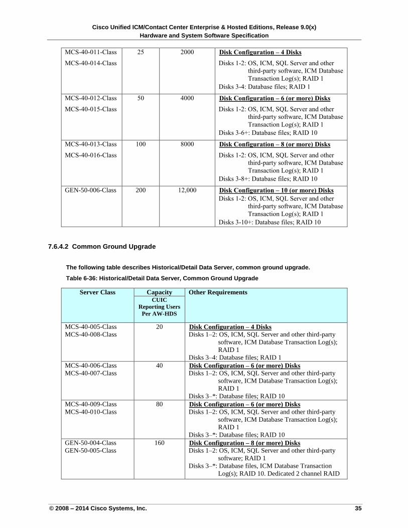
Cisco Unified ICM/Contact Center Enterprise & Hosted Editions, Release 9.0(x)
Hardware and System Software Specification
© 2008 – 2014 Cisco Systems, Inc. 35
7.6.4.2 Common Ground Upgrade
The following table describes Historical/Detail Data Server, common ground upgrade.
Table 6-36: Historical/Detail Data Server, Common Ground Upgrade
MCS-40-011-Class
MCS-40-014-Class
25 2000 UDisk Configuration – 4 Disks
Disks 1-2: OS, ICM, SQL Server and other
third-party software, ICM Database
Transaction Log(s); RAID 1
Disks 3-4: Database files; RAID 1
MCS-40-012-Class
MCS-40-015-Class
50 4000 UDisk Configuration – 6 (or more) Disks
Disks 1-2: OS, ICM, SQL Server and other
third-party software, ICM Database
Transaction Log(s); RAID 1
Disks 3-6+: Database files; RAID 10
MCS-40-013-Class
MCS-40-016-Class
100 8000 UDisk Configuration – 8 (or more) Disks
Disks 1-2: OS, ICM, SQL Server and other
third-party software, ICM Database
Transaction Log(s); RAID 1
Disks 3-8+: Database files; RAID 10
GEN-50-006-Class 200 12,000 UDisk Configuration – 10 (or more) Disks
Disks 1-2: OS, ICM, SQL Server and other
third-party software, ICM Database
Transaction Log(s); RAID 1
Disks 3-10+: Database files; RAID 10
Server Class Capacity Other Requirements CUIC
Reporting Users
Per AW-HDS
MCS-40-005-Class
MCS-40-008-Class
20 UDisk Configuration – 4 DisksU Disks 1–2: OS, ICM, SQL Server and other third-party
software, ICM Database Transaction Log(s);
RAID 1
Disks 3–4: Database files; RAID 1
MCS-40-006-Class
MCS-40-007-Class
40 UDisk Configuration – 6 (or more) DisksU Disks 1–2: OS, ICM, SQL Server and other third-party
software, ICM Database Transaction Log(s);
RAID 1
Disks 3–*: Database files; RAID 10
MCS-40-009-Class
MCS-40-010-Class
80 UDisk Configuration – 6 (or more) DisksU Disks 1–2: OS, ICM, SQL Server and other third-party
software, ICM Database Transaction Log(s);
RAID 1
Disks 3–*: Database files; RAID 10
GEN-50-004-Class
GEN-50-005-Class
160 UDisk Configuration – 8 (or more) DisksU Disks 1–2: OS, ICM, SQL Server and other third-party
software; RAID 1
Disks 3–*: Database files, ICM Database Transaction
Log(s); RAID 10. Dedicated 2 channel RAID
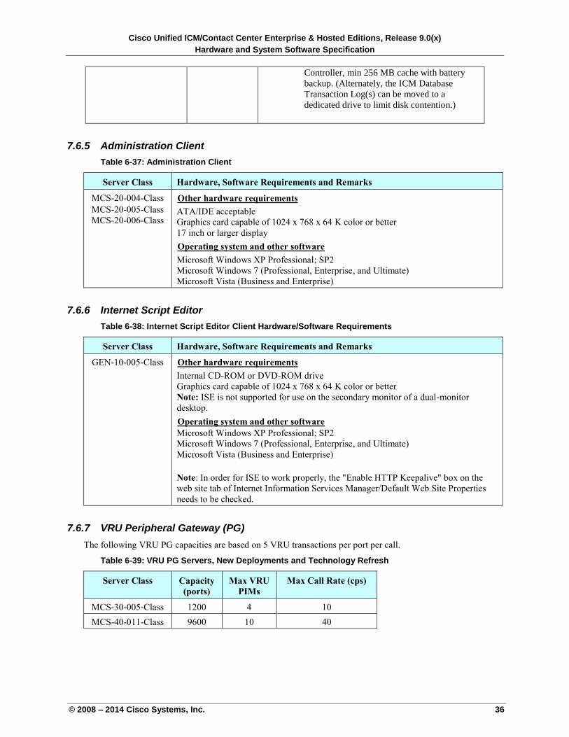
Cisco Unified ICM/Contact Center Enterprise & Hosted Editions, Release 9.0(x)
Hardware and System Software Specification
© 2008 – 2014 Cisco Systems, Inc. 36
7.6.5 Administration Client
Table 6-37: Administration Client
Server Class Hardware, Software Requirements and Remarks
MCS-20-004-Class
MCS-20-005-Class
MCS-20-006-Class
UOther hardware requirements
ATA/IDE acceptable
Graphics card capable of 1024 x 768 x 64 K color or better
17 inch or larger display
UOperating system and other software
Microsoft Windows XP Professional; SP2
Microsoft Windows 7 (Professional, Enterprise, and Ultimate)
Microsoft Vista (Business and Enterprise)
7.6.6 Internet Script Editor
Table 6-38: Internet Script Editor Client Hardware/Software Requirements
Server Class Hardware, Software Requirements and Remarks
GEN-10-005-Class UOther hardware requirements
Internal CD-ROM or DVD-ROM drive
Graphics card capable of 1024 x 768 x 64 K color or better
Note: ISE is not supported for use on the secondary monitor of a dual-monitor
desktop.
UOperating system and other software
Microsoft Windows XP Professional; SP2
Microsoft Windows 7 (Professional, Enterprise, and Ultimate)
Microsoft Vista (Business and Enterprise)
Note: In order for ISE to work properly, the "Enable HTTP Keepalive" box on the
web site tab of Internet Information Services Manager/Default Web Site Properties
needs to be checked.
7.6.7 VRU Peripheral Gateway (PG)
The following VRU PG capacities are based on 5 VRU transactions per port per call.
Table 6-39: VRU PG Servers, New Deployments and Technology Refresh
Server Class Capacity
(ports)
Max VRU
PIMs
Max Call Rate (cps)
MCS-30-005-Class 1200 4 10
MCS-40-011-Class 9600 10 40
Controller, min 256 MB cache with battery
backup. (Alternately, the ICM Database
Transaction Log(s) can be moved to a
dedicated drive to limit disk contention.)
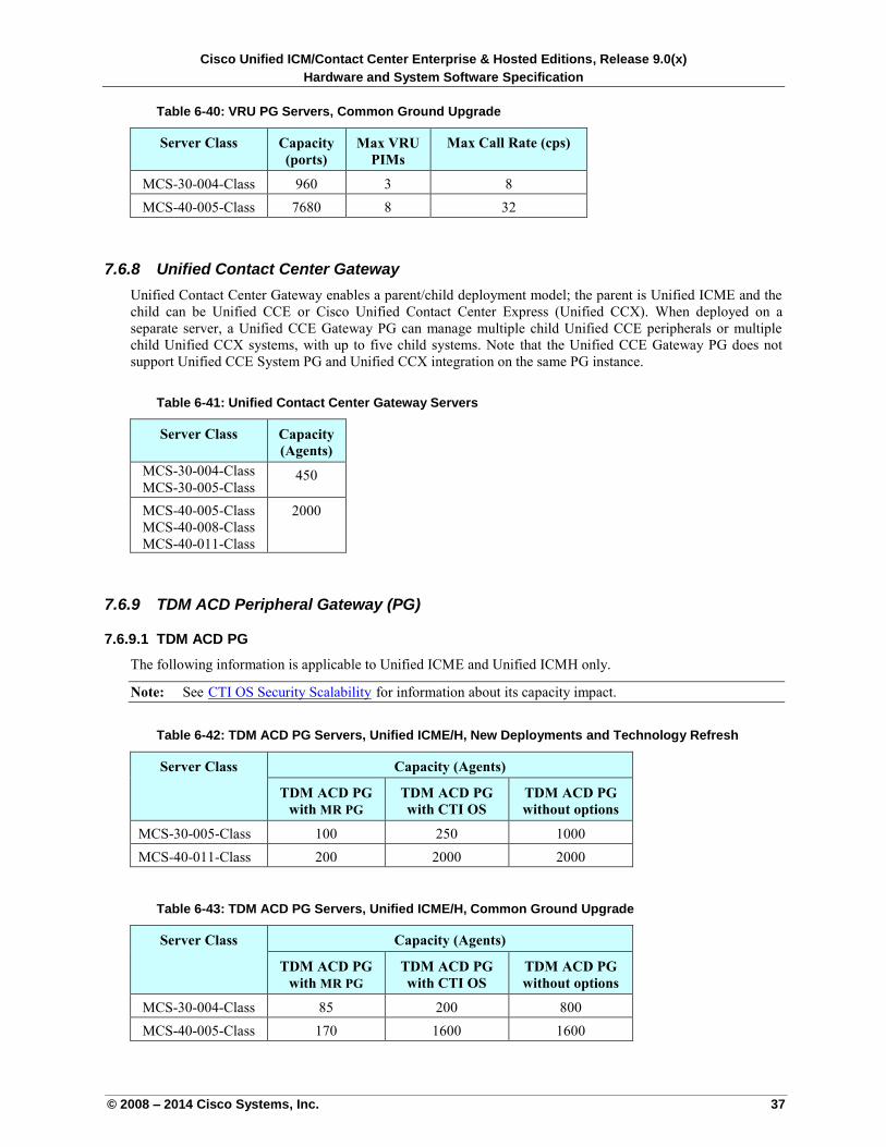
Cisco Unified ICM/Contact Center Enterprise & Hosted Editions, Release 9.0(x)
Hardware and System Software Specification
© 2008 – 2014 Cisco Systems, Inc. 37
Table 6-40: VRU PG Servers, Common Ground Upgrade
Server Class Capacity
(ports)
Max VRU
PIMs
Max Call Rate (cps)
MCS-30-004-Class 960 3 8
MCS-40-005-Class 7680 8 32
7.6.8 Unified Contact Center Gateway
Unified Contact Center Gateway enables a parent/child deployment model; the parent is Unified ICME and the
child can be Unified CCE or Cisco Unified Contact Center Express (Unified CCX). When deployed on a
separate server, a Unified CCE Gateway PG can manage multiple child Unified CCE peripherals or multiple
child Unified CCX systems, with up to five child systems. Note that the Unified CCE Gateway PG does not
support Unified CCE System PG and Unified CCX integration on the same PG instance.
Table 6-41: Unified Contact Center Gateway Servers
Server Class Capacity
(Agents)
MCS-30-004-Class
MCS-30-005-Class 450
MCS-40-005-Class
MCS-40-008-Class
MCS-40-011-Class
2000
7.6.9 TDM ACD Peripheral Gateway (PG)
7.6.9.1 TDM ACD PG
The following information is applicable to Unified ICME and Unified ICMH only.
Note: See UCTI OS Security ScalabilityU for information about its capacity impact.
Table 6-42: TDM ACD PG Servers, Unified ICME/H, New Deployments and Technology Refresh
Server Class Capacity (Agents)
TDM ACD PG
with MR PG
TDM ACD PG
with CTI OS
TDM ACD PG
without options
MCS-30-005-Class 100 250 1000
MCS-40-011-Class 200 2000 2000
Table 6-43: TDM ACD PG Servers, Unified ICME/H, Common Ground Upgrade
Server Class Capacity (Agents)
TDM ACD PG
with MR PG
TDM ACD PG
with CTI OS
TDM ACD PG
without options
MCS-30-004-Class 85 200 800
MCS-40-005-Class 170 1600 1600
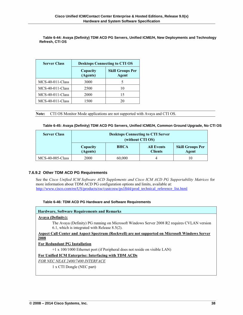
Cisco Unified ICM/Contact Center Enterprise & Hosted Editions, Release 9.0(x)
Hardware and System Software Specification
© 2008 – 2014 Cisco Systems, Inc. 38
Table 6-44: Avaya (Definity) TDM ACD PG Servers, Unified ICME/H, New Deployments and Technology Refresh, CTI OS
Server Class Desktops Connecting to CTI OS
Capacity
(Agents)
Skill Groups Per
Agent
MCS-40-011-Class 3000 5
MCS-40-011-Class 2500 10
MCS-40-011-Class 2000 15
MCS-40-011-Class 1500 20
Note: CTI OS Monitor Mode applications are not supported with Avaya and CTI OS.
Table 6-45: Avaya (Definity) TDM ACD PG Servers, Unified ICME/H, Common Ground Upgrade, No CTI OS
Server Class Desktops Connecting to CTI Server
(without CTI OS)
Capacity
(Agents)
BHCA All Events
Clients
Skill Groups Per
Agent
MCS-40-005-Class 2000 60,000 4 10
7.6.9.2 Other TDM ACD PG Requirements
See the Cisco Unified ICM Software ACD Supplements and Cisco ICM ACD PG Supportability Matrices for
more information about TDM ACD PG configuration options and limits, available at:
Uhttp://www.cisco.com/en/US/products/sw/custcosw/ps1844/prod_technical_reference_list.html U
Table 6-46: TDM ACD PG Hardware and Software Requirements
Hardware, Software Requirements and Remarks
UAvaya (Definity):
The Avaya (Definity) PG running on Microsoft Windows Server 2008 R2 requires CVLAN version
6.1, which is integrated with Release 8.5(2).
UAspect Call Center and Aspect Spectrum (Rockwell) are not supported on Microsoft Windows Server
2008
UFor Redundant PG Installation
+1 x 100/1000 Ethernet port (if Peripheral does not reside on visible LAN)
UFor Unified ICM Enterprise: Interfacing with TDM ACDs
UFOR NEC NEAX 2400/7400 INTERFACE
1 x CTI Dongle (NEC part)
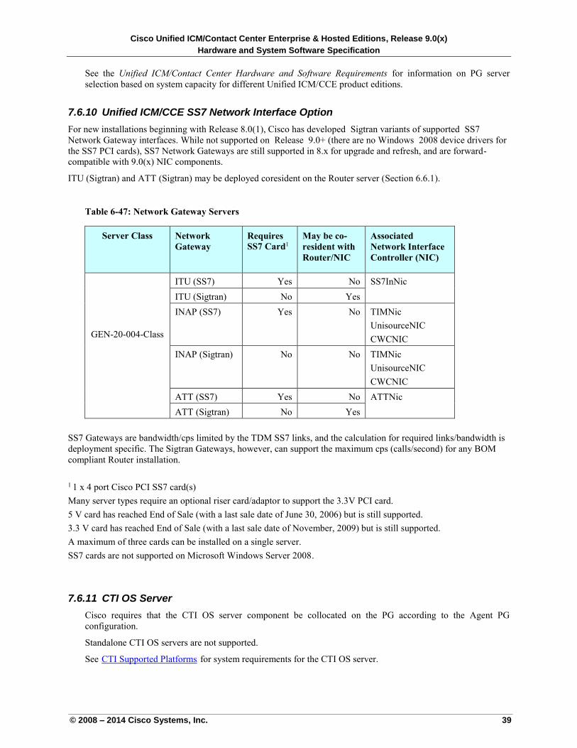
Cisco Unified ICM/Contact Center Enterprise & Hosted Editions, Release 9.0(x)
Hardware and System Software Specification
© 2008 – 2014 Cisco Systems, Inc. 39
See the Unified ICM/Contact Center Hardware and Software Requirements for information on PG server
selection based on system capacity for different Unified ICM/CCE product editions.
7.6.10 Unified ICM/CCE SS7 Network Interface Option
For new installations beginning with Release 8.0(1), Cisco has developed Sigtran variants of supported SS7
Network Gateway interfaces. While not supported on Release 9.0+ (there are no Windows 2008 device drivers for
the SS7 PCI cards), SS7 Network Gateways are still supported in 8.x for upgrade and refresh, and are forward-
compatible with 9.0(x) NIC components.
ITU (Sigtran) and ATT (Sigtran) may be deployed coresident on the Router server (Section 6.6.1).
Table 6-47: Network Gateway Servers
Server Class Network
Gateway
Requires
SS7 Card1
May be co-
resident with
Router/NIC
Associated
Network Interface
Controller (NIC)
GEN-20-004-Class
ITU (SS7) Yes No SS7InNic
ITU (Sigtran) No Yes
INAP (SS7) Yes
No
TIMNic
UnisourceNIC
CWCNIC
INAP (Sigtran) No No TIMNic
UnisourceNIC
CWCNIC
ATT (SS7) Yes No ATTNic
ATT (Sigtran) No Yes
SS7 Gateways are bandwidth/cps limited by the TDM SS7 links, and the calculation for required links/bandwidth is
deployment specific. The Sigtran Gateways, however, can support the maximum cps (calls/second) for any BOM
compliant Router installation.
1 1 x 4 port Cisco PCI SS7 card(s)
Many server types require an optional riser card/adaptor to support the 3.3V PCI card.
5 V card has reached End of Sale (with a last sale date of June 30, 2006) but is still supported.
3.3 V card has reached End of Sale (with a last sale date of November, 2009) but is still supported.
A maximum of three cards can be installed on a single server.
SS7 cards are not supported on Microsoft Windows Server 2008.
7.6.11 CTI OS Server
Cisco requires that the CTI OS server component be collocated on the PG according to the Agent PG
configuration.
Standalone CTI OS servers are not supported.
See UCTI Supported PlatformsU for system requirements for the CTI OS server.
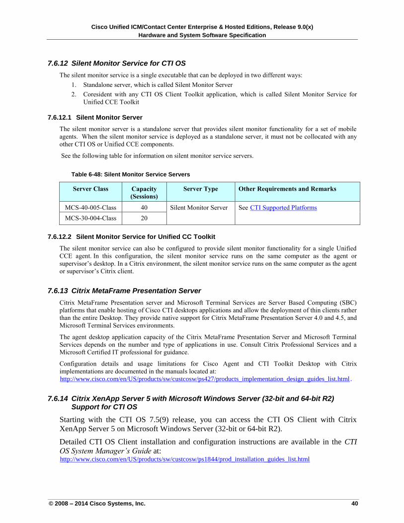
Cisco Unified ICM/Contact Center Enterprise & Hosted Editions, Release 9.0(x)
Hardware and System Software Specification
© 2008 – 2014 Cisco Systems, Inc. 40
7.6.12 Silent Monitor Service for CTI OS
The silent monitor service is a single executable that can be deployed in two different ways:
1. Standalone server, which is called Silent Monitor Server
2. Coresident with any CTI OS Client Toolkit application, which is called Silent Monitor Service for
Unified CCE Toolkit
7.6.12.1 Silent Monitor Server
The silent monitor server is a standalone server that provides silent monitor functionality for a set of mobile
agents. When the silent monitor service is deployed as a standalone server, it must not be collocated with any
other CTI OS or Unified CCE components.
See the following table for information on silent monitor service servers.
Table 6-48: Silent Monitor Service Servers
Server Class Capacity
(Sessions)
Server Type Other Requirements and Remarks
MCS-40-005-Class 40 Silent Monitor Server See UCTI Supported PlatformsU
MCS-30-004-Class 20
7.6.12.2 Silent Monitor Service for Unified CC Toolkit
The silent monitor service can also be configured to provide silent monitor functionality for a single Unified
CCE agent. In this configuration, the silent monitor service runs on the same computer as the agent or
supervisor’s desktop. In a Citrix environment, the silent monitor service runs on the same computer as the agent
or supervisor’s Citrix client.
7.6.13 Citrix MetaFrame Presentation Server
Citrix MetaFrame Presentation server and Microsoft Terminal Services are Server Based Computing (SBC)
platforms that enable hosting of Cisco CTI desktops applications and allow the deployment of thin clients rather
than the entire Desktop. They provide native support for Citrix MetaFrame Presentation Server 4.0 and 4.5, and
Microsoft Terminal Services environments.
The agent desktop application capacity of the Citrix MetaFrame Presentation Server and Microsoft Terminal
Services depends on the number and type of applications in use. Consult Citrix Professional Services and a
Microsoft Certified IT professional for guidance.
Configuration details and usage limitations for Cisco Agent and CTI Toolkit Desktop with Citrix
implementations are documented in the manuals located at:
Uhttp://www.cisco.com/en/US/products/sw/custcosw/ps427/products_implementation_design_guides_list.html U.
7.6.14 Citrix XenApp Server 5 with Microsoft Windows Server (32-bit and 64-bit R2) Support for CTI OS
Starting with the CTI OS 7.5(9) release, you can access the CTI OS Client with Citrix
XenApp Server 5 on Microsoft Windows Server (32-bit or 64-bit R2).
Detailed CTI OS Client installation and configuration instructions are available in the CTI
OS System Manager’s Guide at: Uhttp://www.cisco.com/en/US/products/sw/custcosw/ps1844/prod_installation_guides_list.htmlU
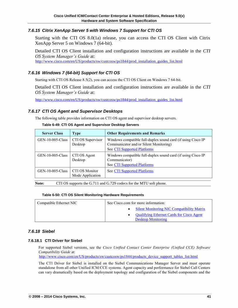
Cisco Unified ICM/Contact Center Enterprise & Hosted Editions, Release 9.0(x)
Hardware and System Software Specification
© 2008 – 2014 Cisco Systems, Inc. 41
7.6.15 Citrix XenApp Server 5 with Windows 7 Support for CTI OS
Starting with the CTI OS 8.0(1a) release, you can access the CTI OS Client with Citrix
XenApp Server 5 on Windows 7 (64-bit).
Detailed CTI OS Client installation and configuration instructions are available in the CTI
OS System Manager’s Guide at: Uhttp://www.cisco.com/en/US/products/sw/custcosw/ps1844/prod_installation_guides_list.htmlU
7.6.16 Windows 7 (64-bit) Support for CTI OS
Starting with CTI OS Release 8.5(2), you can access the CTI OS Client on Windows 7 64-bit.
Detailed CTI OS Client installation and configuration instructions are available in the CTI
OS System Manager’s Guide at:
Uhttp://www.cisco.com/en/US/products/sw/custcosw/ps1844/prod_installation_guides_list.html U
7.6.17 CTI OS Agent and Supervisor Desktops
The following table provides information on CTI OS agent and supervisor desktop servers.
Table 6-49: CTI OS Agent and Supervisor Desktop Servers
Server Class Type Other Requirements and Remarks
GEN-10-005-Class CTI OS Supervisor
Desktop
Windows compatible full-duplex sound card (if using Cisco IP
Communicator and/or Silent Monitoring)
See UCTI Supported PlatformsU
GEN-10-005-Class CTI OS Agent
Desktop
Windows compatible full-duplex sound card (if using Cisco IP
Communicator)
See UCTI Supported PlatformsU
GEN-10-005-Class CTI OS Monitor
Mode Application
See UCTI Supported PlatformsU
Note: CTI OS supports the G.711 and G.729 codecs for the MTU soft phone.
Table 6-50: CTI OS Silent Monitoring Hardware Requirements
Compatible Ethernet NIC See Cisco.com for more information:
USilent Monitoring NIC Compatibility MatrixU
UQualifying Ethernet Cards for Cisco Agent
Desktop MonitoringU
7.6.18 Siebel
7.6.18.1 CTI Driver for Siebel
For supported Siebel versions, see the Cisco Unified Contact Center Enterprise (Unified CCE) Software
Compatibility Guide at:
Uhttp://www.cisco.com/en/US/products/sw/custcosw/ps1844/products_device_support_tables_list.html
The CTI Driver for Siebel is installed on the Siebel Communications Manager Server and must operate
standalone from all other Unified ICM/CCE systems. Agent capacity and performance for Siebel Call Centers
can vary dramatically based on the deployment topology and configuration of the Siebel components and the
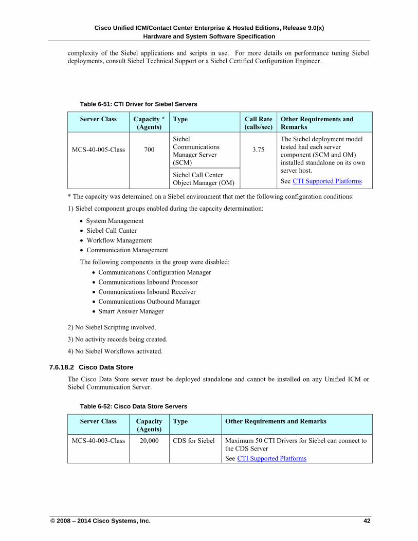
Cisco Unified ICM/Contact Center Enterprise & Hosted Editions, Release 9.0(x)
Hardware and System Software Specification
© 2008 – 2014 Cisco Systems, Inc. 42
complexity of the Siebel applications and scripts in use. For more details on performance tuning Siebel
deployments, consult Siebel Technical Support or a Siebel Certified Configuration Engineer.
Table 6-51: CTI Driver for Siebel Servers
Server Class Capacity *
(Agents)
Type Call Rate
(calls/sec)
Other Requirements and
Remarks
MCS-40-005-Class
700
Siebel
Communications
Manager Server
(SCM)
3.75
The Siebel deployment model
tested had each server
component (SCM and OM)
installed standalone on its own
server host.
See UCTI Supported PlatformsU Siebel Call Center
Object Manager (OM)
* The capacity was determined on a Siebel environment that met the following configuration conditions:
1) Siebel component groups enabled during the capacity determination:
System Management
Siebel Call Canter
Workflow Management
Communication Management
The following components in the group were disabled:
Communications Configuration Manager
Communications Inbound Processor
Communications Inbound Receiver
Communications Outbound Manager
Smart Answer Manager
2) No Siebel Scripting involved.
3) No activity records being created.
4) No Siebel Workflows activated.
7.6.18.2 Cisco Data Store
The Cisco Data Store server must be deployed standalone and cannot be installed on any Unified ICM or
Siebel Communication Server.
Table 6-52: Cisco Data Store Servers
Server Class Capacity
(Agents)
Type Other Requirements and Remarks
MCS-40-003-Class 20,000 CDS for Siebel Maximum 50 CTI Drivers for Siebel can connect to
the CDS Server
See UCTI Supported PlatformsU
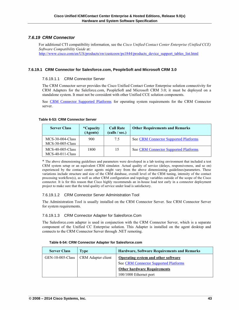
Cisco Unified ICM/Contact Center Enterprise & Hosted Editions, Release 9.0(x)
Hardware and System Software Specification
© 2008 – 2014 Cisco Systems, Inc. 43
7.6.19 CRM Connector
For additional CTI compatibility information, see the Cisco Unified Contact Center Enterprise (Unified CCE)
Software Compatibility Guide at:
Uhttp://www.cisco.com/en/US/products/sw/custcosw/ps1844/products_device_support_tables_list.html U
7.6.19.1 CRM Connector for Salesforce.com, PeopleSoft and Microsoft CRM 3.0
7.6.19.1.1 106BCRM Connector Server
The CRM Connector server provides the Cisco Unified Contact Center Enterprise solution connectivity for
CRM Adapters for the Saleforce.com, PeopleSoft and Microsoft CRM 3.0; it must be deployed on a
standalone system. It must not be coresident with other Unified CCE solution components.
See UCRM Connector Supported PlatformsU for operating system requirements for the CRM Connector
server.
Table 6-53: CRM Connector Server
Server Class *Capacity
(Agents)
Call Rate
(calls / sec.)
Other Requirements and Remarks
MCS-30-004-Class
MCS-30-005-Class
900 7.5 See UCRM Connector Supported PlatformsU
MCS-40-005-Class
MCS-40-011-Class
1800 15 See UCRM Connector Supported PlatformsU
* The above dimensioning guidelines and parameters were developed in a lab testing environment that included a test
CRM system setup or an equivalent CRM simulator. Actual quality of service (delays, responsiveness, and so on)
experienced by the contact center agents might vary from the above dimensioning guidelines/parameters. These
variations include structure and size of the CRM database, overall level of the CRM tuning, intensity of the contact
processing workflow(s), as well as other CRM configuration and topology variables outside of the scope of the Cisco
connector. It is for this reason that Cisco highly recommends an in-house load test early in a connector deployment
project to make sure that the total quality of service under load is satisfactory.
7.6.19.1.2 107BCRM Connector Server Administration Tool
The Administration Tool is usually installed on the CRM Connector Server. See CRM Connector Server
for system requirements.
7.6.19.1.3 108BCRM Connector Adapter for Salesforce.Com
The Salesforce.com adapter is used in conjunction with the CRM Connector Server, which is a separate
component of the Unified CC Enterprise solution. This Adapter is installed on the agent desktop and
connects to the CRM Connector Server through .NET remoting.
Table 6-54: CRM Connector Adapter for Salesforce.com
Server Class Type Hardware, Software Requirements and Remarks
GEN-10-005-Class CRM Adapter client UOperating system and other software
See UCRM Connector Supported Platforms
UOther hardware Requirements
100/1000 Ethernet port
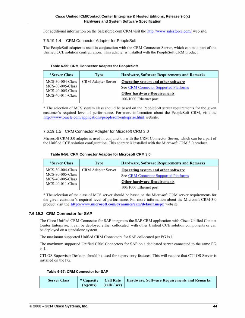
Cisco Unified ICM/Contact Center Enterprise & Hosted Editions, Release 9.0(x)
Hardware and System Software Specification
© 2008 – 2014 Cisco Systems, Inc. 44
For additional information on the Salesforce.com CRM visit the Uhttp://www.salesforce.com/U web site.
7.6.19.1.4 CRM Connector Adapter for PeopleSoft
The PeopleSoft adapter is used in conjunction with the CRM Connector Server, which can be a part of the
Unified CCE solution configuration. This adapter is installed with the PeopleSoft CRM product.
Table 6-55: CRM Connector Adapter for PeopleSoft
*Server Class Type Hardware, Software Requirements and Remarks
MCS-30-004-Class
MCS-30-005-Class
MCS-40-005-Class
MCS-40-011-Class
CRM Adapter Server UOperating system and other software
See UCRM Connector Supported Platforms
UOther hardware Requirements
100/1000 Ethernet port
* The selection of MCS system class should be based on the PeopleSoft server requirements for the given
customer’s required level of performance. For more information about the PeopleSoft CRM, visit the
Uhttp://www.oracle.com/applications/peoplesoft-enterprise.htmlU website.
7.6.19.1.5 CRM Connector Adapter for Microsoft CRM 3.0
Microsoft CRM 3.0 adapter is used in conjunction with the CRM Connector Server, which can be a part of
the Unified CCE solution configuration. This adapter is installed with the Microsoft CRM 3.0 product.
Table 6-56: CRM Connector Adapter for Microsoft CRM 3.0
*Server Class Type Hardware, Software Requirements and Remarks
MCS-30-004-Class
MCS-30-005-Class
MCS-40-005-Class
MCS-40-011-Class
CRM Adapter Server UOperating system and other software
See UCRM Connector Supported Platforms
UOther hardware Requirements
100/1000 Ethernet port
* The selection of the class of MCS server should be based on the Microsoft CRM server requirements for
the given customer’s required level of performance. For more information about the Microsoft CRM 3.0
product visit the Uhttp://www.microsoft.com/dynamics/crm/default.mspxU website.
7.6.19.2 CRM Connector for SAP
The Cisco Unified CRM Connector for SAP integrates the SAP CRM application with Cisco Unified Contact
Center Enterprise; it can be deployed either collocated with other Unified CCE solution components or can
be deployed on a standalone system.
The maximum supported Unified CRM Connectors for SAP collocated per PG is 1.
The maximum supported Unified CRM Connectors for SAP on a dedicated server connected to the same PG
is 1.
CTI OS Supervisor Desktop should be used for supervisory features. This will require that CTI OS Server is
installed on the PG.
Table 6-57: CRM Connector for SAP
Server Class * Capacity
(Agents)
Call Rate
(calls / sec)
Hardware, Software Requirements and Remarks

Cisco Unified ICM/Contact Center Enterprise & Hosted Editions, Release 9.0(x)
Hardware and System Software Specification
© 2008 – 2014 Cisco Systems, Inc. 45
MCS-30-004-Class
MCS-30-005-Class
250 3 UOperating system and other software
See UCRM Connector Supported Platforms
* The above dimensioning guidelines and parameters were developed in a lab testing environment that
included a test CRM system setup or an equivalent CRM simulator. Actual quality of service (delays,
responsiveness, etc.) experienced by the contact center agents might vary from the above dimensioning
guidelines/parameters. These variations include structure and size of the CRM database, overall level of the
CRM tuning, intensity of the contact processing workflow(s), as well as other CRM configuration and
topology variables outside of the scope of the Cisco connector. It is for this reason that Cisco highly
recommends an in-house load test early in a connector deployment project to make sure that the total quality
of service under load is satisfactory.
7.6.19.3 CRM Connector Supported Platforms
Table 6-58: CRM Connector Supported Platforms and Requirements
* The Admin tool can use Microsoft SQL Server Express, which is available from Microsoft at no charge.
1 See the Cisco Unified CRM Connector Implementation and Administration Guide for Microsoft CRM,
Oracle PeopleSoft and Salesforce.com guide for detailed implementation and installation information for
these CRM Connector products.
2 See the Installation and Configuration Guide: Cisco Unified CRM Connector for SAP, Release 1.0(1) for the
CRM Connector for SAP.
N/A = Not Available
N/R = Not Required
7.6.20 Cisco Agent and Supervisor Desktops
Cisco agent and supervisor desktops are used in conjunction with the CAD server, which can be a part of the
Unified CCE solution configuration.
Table 6-59: CAD Agent and Supervisor Desktop Servers
Server Class Type Hardware, Software Requirements and Remarks
CRM Connector
Operating System
Additional Software
Windows Server
2008 R2
Windows XP Pro;
SP2
Windows Vista
Microsoft .NET
Framework V2.0
Microsoft Message Queuing (MSMQ)
Microsoft Internet
Information Server (IIS)
Microsoft SQL
Server
D C O M
ASP.
NET 2.0
JRE 1.6.3
Server N/A N/A N/R N/R
Server Admin Tool
N/A
N/A
N/R
*
N/R
Oracle PeopleSoft Adapter 1
N/A
N/A
N/R
N/R
N/R
N/R
N/R
Microsoft CRM 3.0 Adapter 1
N/A
N/A
N/R
N/R
N/R
Salesforce .com Adapter 1
N/A N/R N/R N/R N/R N/R
SAP 2 N/A N/A N/R N/R N/R N/R N/R N/R N/R
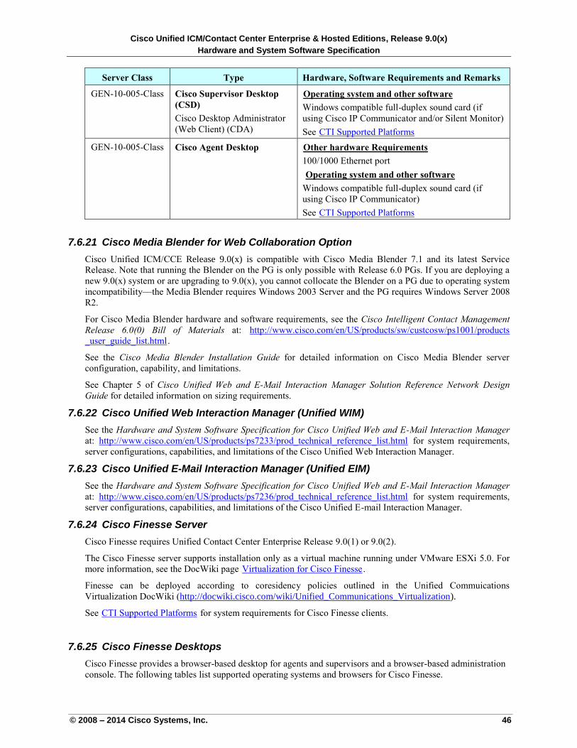
Cisco Unified ICM/Contact Center Enterprise & Hosted Editions, Release 9.0(x)
Hardware and System Software Specification
© 2008 – 2014 Cisco Systems, Inc. 46
Server Class Type Hardware, Software Requirements and Remarks
GEN-10-005-Class Cisco Supervisor Desktop
(CSD)
Cisco Desktop Administrator
(Web Client) (CDA)
UOperating system and other software
Windows compatible full-duplex sound card (if
using Cisco IP Communicator and/or Silent Monitor)
See UCTI Supported PlatformsU
GEN-10-005-Class Cisco Agent Desktop UOther hardware Requirements
100/1000 Ethernet port
UOperating system and other software
Windows compatible full-duplex sound card (if
using Cisco IP Communicator)
See UCTI Supported PlatformsU
7.6.21 Cisco Media Blender for Web Collaboration Option
Cisco Unified ICM/CCE Release 9.0(x) is compatible with Cisco Media Blender 7.1 and its latest Service
Release. Note that running the Blender on the PG is only possible with Release 6.0 PGs. If you are deploying a
new 9.0(x) system or are upgrading to 9.0(x), you cannot collocate the Blender on a PG due to operating system
incompatibility—the Media Blender requires Windows 2003 Server and the PG requires Windows Server 2008
R2.
For Cisco Media Blender hardware and software requirements, see the Cisco Intelligent Contact Management
Release 6.0(0) Bill of Materials at: Uhttp://www.cisco.com/en/US/products/sw/custcosw/ps1001/products
_user_guide_list.htmlU.
See the Cisco Media Blender Installation Guide for detailed information on Cisco Media Blender server
configuration, capability, and limitations.
See Chapter 5 of Cisco Unified Web and E-Mail Interaction Manager Solution Reference Network Design
Guide for detailed information on sizing requirements.
7.6.22 Cisco Unified Web Interaction Manager (Unified WIM)
See the Hardware and System Software Specification for Cisco Unified Web and E-Mail Interaction Manager
at: Uhttp://www.cisco.com/en/US/products/ps7233/prod_technical_reference_list.html U for system requirements,
server configurations, capabilities, and limitations of the Cisco Unified Web Interaction Manager.
7.6.23 Cisco Unified E-Mail Interaction Manager (Unified EIM)
See the Hardware and System Software Specification for Cisco Unified Web and E-Mail Interaction Manager
at: Uhttp://www.cisco.com/en/US/products/ps7236/prod_technical_reference_list.html U for system requirements,
server configurations, capabilities, and limitations of the Cisco Unified E-mail Interaction Manager.
7.6.24 Cisco Finesse Server
Cisco Finesse requires Unified Contact Center Enterprise Release 9.0(1) or 9.0(2).
The Cisco Finesse server supports installation only as a virtual machine running under VMware ESXi 5.0. For
more information, see the DocWiki page UVirtualization for Cisco FinesseU.
Finesse can be deployed according to coresidency policies outlined in the Unified Commuications
Virtualization DocWiki (http://docwiki.cisco.com/wiki/Unified_Communications_Virtualization).
See UCTI Supported PlatformsU for system requirements for Cisco Finesse clients.
7.6.25 Cisco Finesse Desktops
Cisco Finesse provides a browser-based desktop for agents and supervisors and a browser-based administration
console. The following tables list supported operating systems and browsers for Cisco Finesse.
Cisco Unified ICM/Contact Center Enterprise & Hosted Editions, Release 9.0(x)
Hardware and System Software Specification
© 2008 – 2014 Cisco Systems, Inc. 47
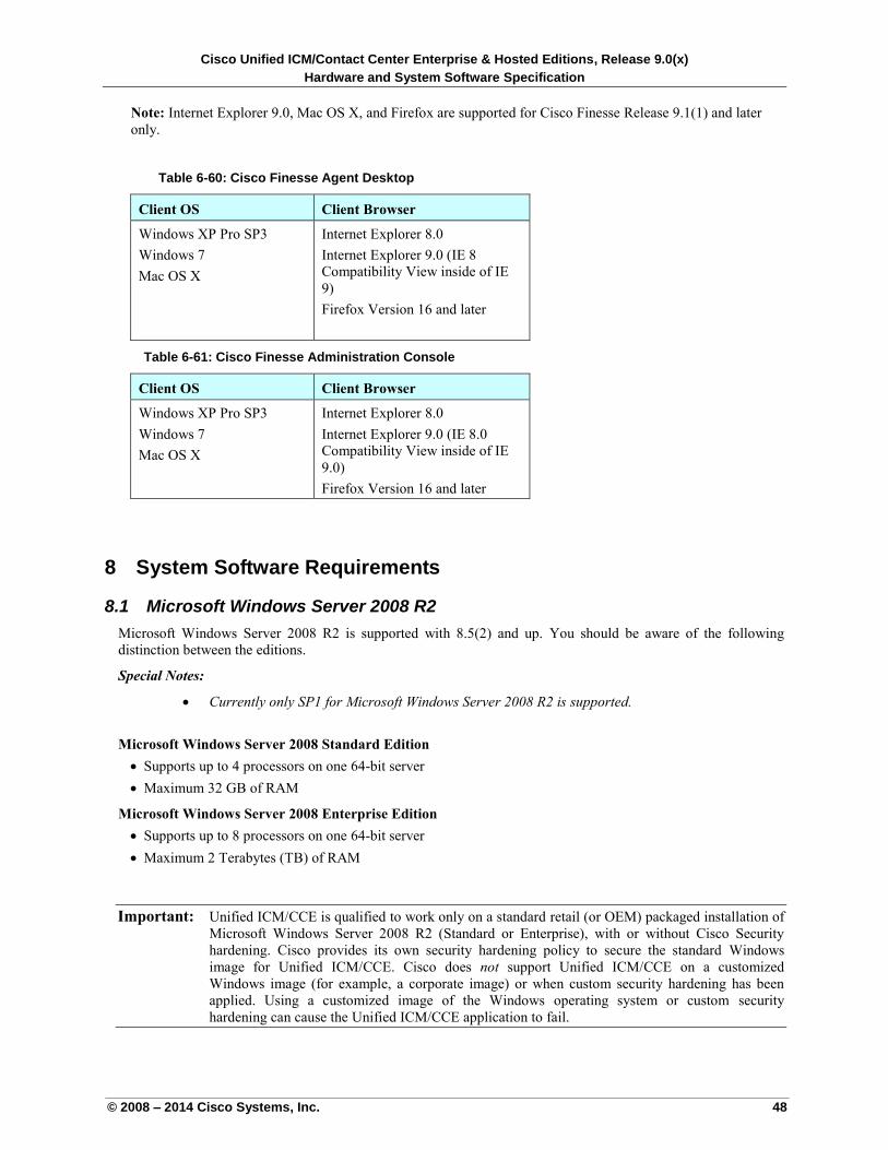
Cisco Unified ICM/Contact Center Enterprise & Hosted Editions, Release 9.0(x)
Hardware and System Software Specification
© 2008 – 2014 Cisco Systems, Inc. 48
Note: Internet Explorer 9.0, Mac OS X, and Firefox are supported for Cisco Finesse Release 9.1(1) and later
only.
Table 6-60: Cisco Finesse Agent Desktop
Client OS Client Browser
Windows XP Pro SP3
Windows 7
Mac OS X
Internet Explorer 8.0
Internet Explorer 9.0 (IE 8
Compatibility View inside of IE
9)
Firefox Version 16 and later
Table 6-61: Cisco Finesse Administration Console
Client OS Client Browser
Windows XP Pro SP3
Windows 7
Mac OS X
Internet Explorer 8.0
Internet Explorer 9.0 (IE 8.0
Compatibility View inside of IE
9.0)
Firefox Version 16 and later
8 System Software Requirements
8.1 Microsoft Windows Server 2008 R2
Microsoft Windows Server 2008 R2 is supported with 8.5(2) and up. You should be aware of the following
distinction between the editions.
Special Notes:
Currently only SP1 for Microsoft Windows Server 2008 R2 is supported.
Microsoft Windows Server 2008 Standard Edition
Supports up to 4 processors on one 64-bit server
Maximum 32 GB of RAM
Microsoft Windows Server 2008 Enterprise Edition
Supports up to 8 processors on one 64-bit server
Maximum 2 Terabytes (TB) of RAM
Important: Unified ICM/CCE is qualified to work only on a standard retail (or OEM) packaged installation of
Microsoft Windows Server 2008 R2 (Standard or Enterprise), with or without Cisco Security
hardening. Cisco provides its own security hardening policy to secure the standard Windows
image for Unified ICM/CCE. Cisco does not support Unified ICM/CCE on a customized
Windows image (for example, a corporate image) or when custom security hardening has been
applied. Using a customized image of the Windows operating system or custom security
hardening can cause the Unified ICM/CCE application to fail.
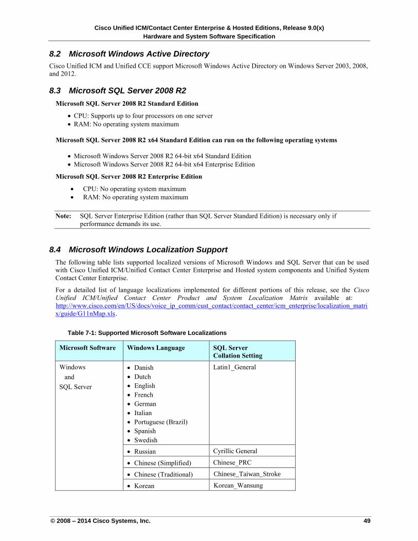
Cisco Unified ICM/Contact Center Enterprise & Hosted Editions, Release 9.0(x)
Hardware and System Software Specification
© 2008 – 2014 Cisco Systems, Inc. 49
8.2 Microsoft Windows Active Directory
Cisco Unified ICM and Unified CCE support Microsoft Windows Active Directory on Windows Server 2003, 2008,
and 2012.
8.3 Microsoft SQL Server 2008 R2
Microsoft SQL Server 2008 R2 Standard Edition
CPU: Supports up to four processors on one server
RAM: No operating system maximum
Microsoft SQL Server 2008 R2 x64 Standard Edition can run on the following operating systems
Microsoft Windows Server 2008 R2 64-bit x64 Standard Edition
Microsoft Windows Server 2008 R2 64-bit x64 Enterprise Edition
Microsoft SQL Server 2008 R2 Enterprise Edition
CPU: No operating system maximum
RAM: No operating system maximum
Note: SQL Server Enterprise Edition (rather than SQL Server Standard Edition) is necessary only if
performance demands its use.
8.4 Microsoft Windows Localization Support
The following table lists supported localized versions of Microsoft Windows and SQL Server that can be used
with Cisco Unified ICM/Unified Contact Center Enterprise and Hosted system components and Unified System
Contact Center Enterprise.
For a detailed list of language localizations implemented for different portions of this release, see the Cisco
Unified ICM/Unified Contact Center Product and System Localization Matrix available at:
Uhttp://www.cisco.com/en/US/docs/voice_ip_comm/cust_contact/contact_center/icm_enterprise/localization_matri
x/guide/G11nMap.xlsU.
Table 7-1: Supported Microsoft Software Localizations
Microsoft Software Windows Language SQL Server
Collation Setting
Windows
and
SQL Server
Danish
Dutch
English
French
German
Italian
Portuguese (Brazil)
Spanish
Swedish
Latin1_General
Russian Cyrillic General
Chinese (Simplified) Chinese_PRC
Chinese (Traditional) Chinese_Taiwan_Stroke
Korean Korean_Wansung
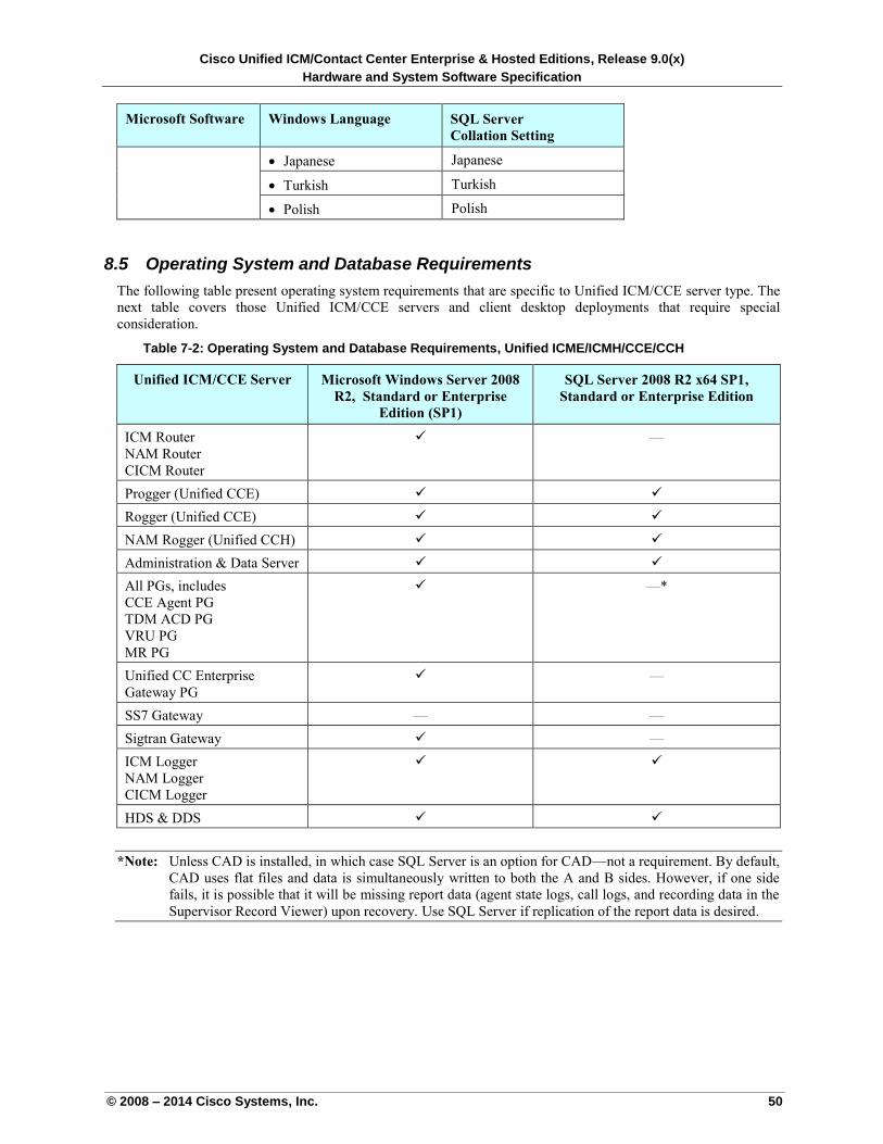
Cisco Unified ICM/Contact Center Enterprise & Hosted Editions, Release 9.0(x)
Hardware and System Software Specification
© 2008 – 2014 Cisco Systems, Inc. 50
Microsoft Software Windows Language SQL Server
Collation Setting
Japanese Japanese
Turkish Turkish
Polish Polish
8.5 Operating System and Database Requirements
The following table present operating system requirements that are specific to Unified ICM/CCE server type. The
next table covers those Unified ICM/CCE servers and client desktop deployments that require special
consideration.
Table 7-2: Operating System and Database Requirements, Unified ICME/ICMH/CCE/CCH
Unified ICM/CCE Server Microsoft Windows Server 2008
R2, Standard or Enterprise
Edition (SP1)
SQL Server 2008 R2 x64 SP1,
Standard or Enterprise Edition
ICM Router
NAM Router
CICM Router
—
Progger (Unified CCE)
Rogger (Unified CCE)
NAM Rogger (Unified CCH)
Administration & Data Server
All PGs, includes
CCE Agent PG
TDM ACD PG
VRU PG
MR PG
—*
Unified CC Enterprise
Gateway PG
—
SS7 Gateway — —
Sigtran Gateway —
ICM Logger
NAM Logger
CICM Logger
HDS & DDS
*Note: Unless CAD is installed, in which case SQL Server is an option for CAD—not a requirement. By default,
CAD uses flat files and data is simultaneously written to both the A and B sides. However, if one side
fails, it is possible that it will be missing report data (agent state logs, call logs, and recording data in the
Supervisor Record Viewer) upon recovery. Use SQL Server if replication of the report data is desired.
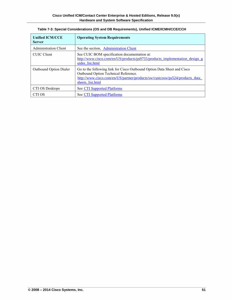
Cisco Unified ICM/Contact Center Enterprise & Hosted Editions, Release 9.0(x)
Hardware and System Software Specification
© 2008 – 2014 Cisco Systems, Inc. 51
Table 7-3: Special Considerations (OS and DB Requirements), Unified ICME/ICMH/CCE/CCH
Unified ICM/CCE
Server
Operating System Requirements
Administration Client See the section, UAdministration ClientU
CUIC Client See CUIC BOM specification documentation at:
http://www.cisco.com/en/US/products/ps9755/products_implementation_design_g
uides_list.htmlU
Outbound Option Dialer Go to the following link for Cisco Outbound Option Data Sheet and Cisco
Outbound Option Technical Reference.
Uhttp://www.cisco.com/en/US/partner/products/sw/custcosw/ps524/products_data_
sheets_list.htmlU
CTI OS Desktops See UCTI Supported PlatformsU
CTI OS See UCTI Supported PlatformsU
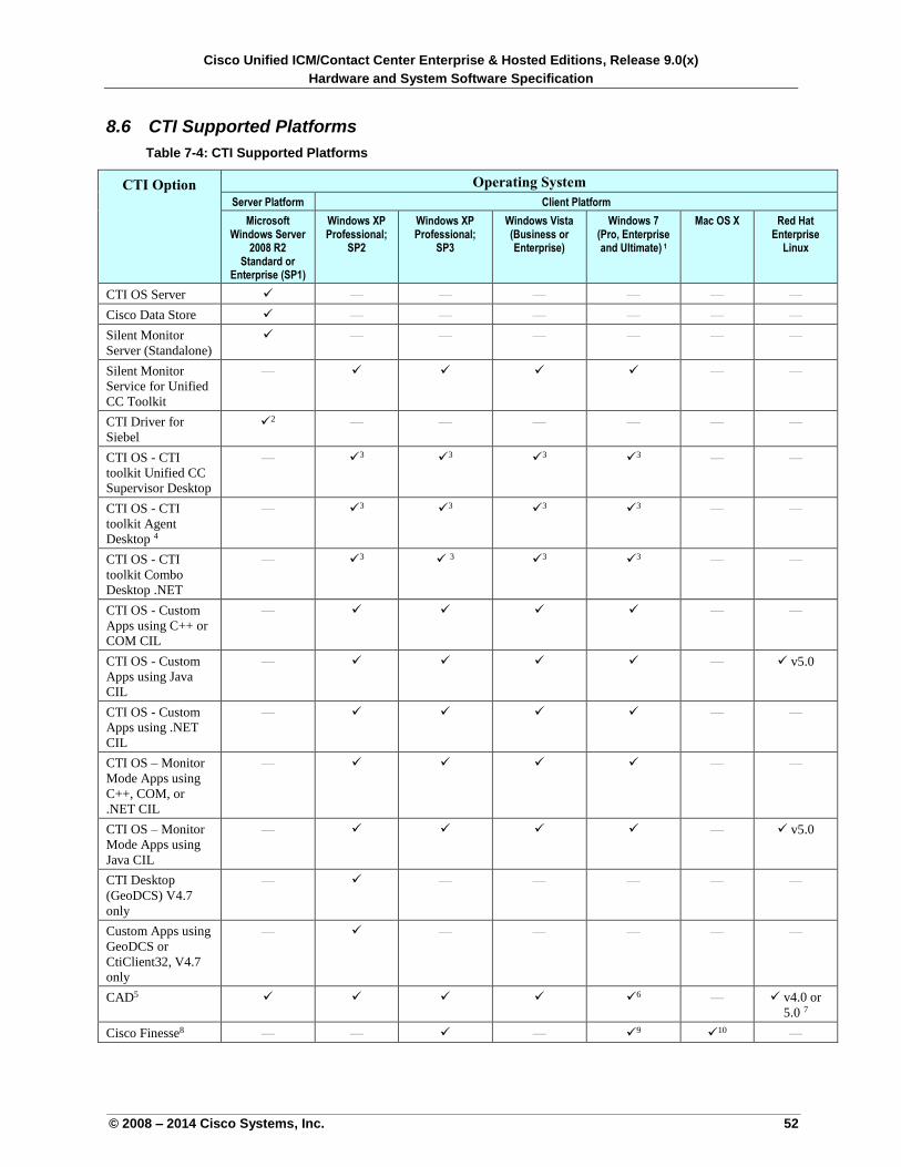
Cisco Unified ICM/Contact Center Enterprise & Hosted Editions, Release 9.0(x)
Hardware and System Software Specification
© 2008 – 2014 Cisco Systems, Inc. 52
8.6 CTI Supported Platforms
Table 7-4: CTI Supported Platforms
CTI Option Operating System
Server Platform Client Platform
Microsoft Windows Server
2008 R2 Standard or
Enterprise (SP1)
Windows XP Professional;
SP2
Windows XP Professional;
SP3
Windows Vista (Business or Enterprise)
Windows 7
(Pro, Enterprise and Ultimate) 1
Mac OS X Red Hat Enterprise
Linux
CTI OS Server — — — — — —
Cisco Data Store — — — — — —
Silent Monitor
Server (Standalone)
— — — — — —
Silent Monitor
Service for Unified
CC Toolkit
— — —
CTI Driver for
Siebel
2 — — — — — —
CTI OS - CTI
toolkit Unified CC
Supervisor Desktop
— 3
3 3
3 — —
CTI OS - CTI
toolkit Agent
Desktop 4
— 3
3 3
3 — —
CTI OS - CTI
toolkit Combo
Desktop .NET
— 3 3
3 3 — —
CTI OS - Custom
Apps using C++ or
COM CIL
— — —
CTI OS - Custom
Apps using Java
CIL
— — v5.0
CTI OS - Custom
Apps using .NET
CIL
— — —
CTI OS – Monitor
Mode Apps using
C++, COM, or
.NET CIL
— — —
CTI OS – Monitor
Mode Apps using
Java CIL
— — v5.0
CTI Desktop
(GeoDCS) V4.7
only
— — — — — —
Custom Apps using
GeoDCS or
CtiClient32, V4.7
only
— — — — — —
CAD5 6 — v4.0 or
5.0 7
Cisco Finesse8 — — — 9
10 —
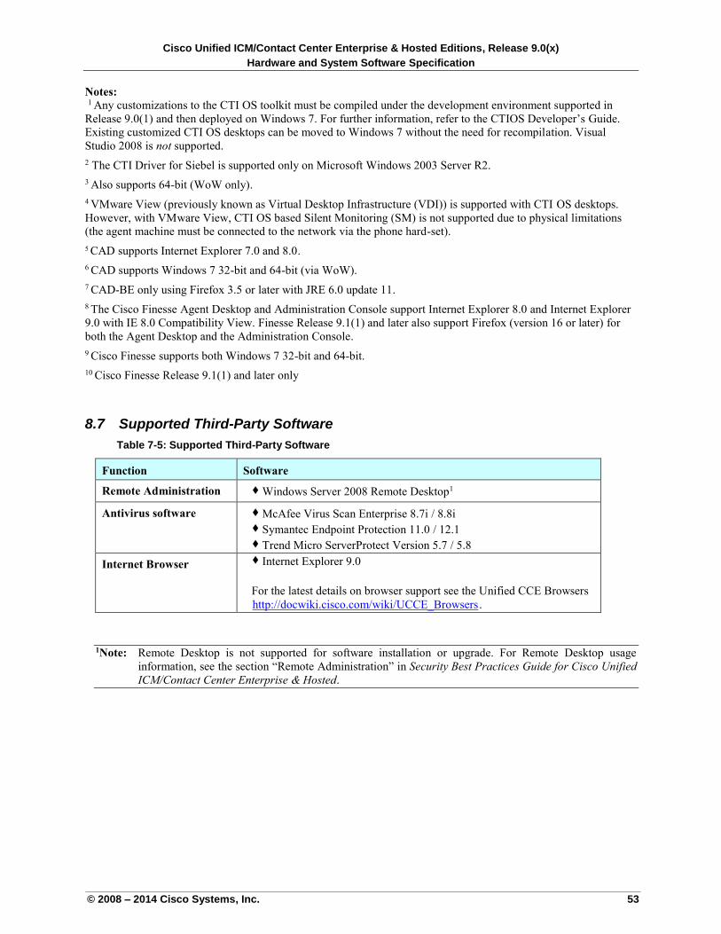
Cisco Unified ICM/Contact Center Enterprise & Hosted Editions, Release 9.0(x)
Hardware and System Software Specification
© 2008 – 2014 Cisco Systems, Inc. 53
Notes:
1 Any customizations to the CTI OS toolkit must be compiled under the development environment supported in
Release 9.0(1) and then deployed on Windows 7. For further information, refer to the CTIOS Developer’s Guide.
Existing customized CTI OS desktops can be moved to Windows 7 without the need for recompilation. Visual
Studio 2008 is not supported.
2 The CTI Driver for Siebel is supported only on Microsoft Windows 2003 Server R2.
3 Also supports 64-bit (WoW only).
4 VMware View (previously known as Virtual Desktop Infrastructure (VDI)) is supported with CTI OS desktops.
However, with VMware View, CTI OS based Silent Monitoring (SM) is not supported due to physical limitations
(the agent machine must be connected to the network via the phone hard-set).
5 CAD supports Internet Explorer 7.0 and 8.0.
6 CAD supports Windows 7 32-bit and 64-bit (via WoW).
7 CAD-BE only using Firefox 3.5 or later with JRE 6.0 update 11.
8 The Cisco Finesse Agent Desktop and Administration Console support Internet Explorer 8.0 and Internet Explorer
9.0 with IE 8.0 Compatibility View. Finesse Release 9.1(1) and later also support Firefox (version 16 or later) for
both the Agent Desktop and the Administration Console.
9 Cisco Finesse supports both Windows 7 32-bit and 64-bit.
10 Cisco Finesse Release 9.1(1) and later only
8.7 Supported Third-Party Software
Table 7-5: Supported Third-Party Software
Function Software
Remote Administration Windows Server 2008 Remote Desktop1
Antivirus software McAfee Virus Scan Enterprise 8.7i / 8.8i Symantec Endpoint Protection 11.0 / 12.1 Trend Micro ServerProtect Version 5.7 / 5.8
Internet Browser Internet Explorer 9.0
For the latest details on browser support see the Unified CCE Browsers
Uhttp://docwiki.cisco.com/wiki/UCCE_BrowsersU.
1Note: Remote Desktop is not supported for software installation or upgrade. For Remote Desktop usage
information, see the section “Remote Administration” in Security Best Practices Guide for Cisco Unified
ICM/Contact Center Enterprise & Hosted.
Cisco Unified ICM/Contact Center Enterprise & Hosted Editions, Release 9.0(x)
Hardware and System Software Specification
© 2008 – 2014 Cisco Systems, Inc. 54
Remote Management and Support
Remote management capability allows Cisco TAC support or Cisco partners to provide system maintenance and
system troubleshooting from a remote site.
You can provide remote management and remote support capability in one of the following two ways:
Provide secured VPN to your network where your Unified ICM/CCE server resides.
8.8 Server Virtualization
Server virtualization allows customers to reduce data center footprint and introduces VMware deployment and
management tools into the contact center. The following sections describe virtualization options for Cisco MCS
and UCS series servers. Cisco supports specific Unified ICM/CC components on virtual machines. However,
Cisco does not provide technical support for VMware products. Contact VMware or VMware partners for product
support and training for all VMware products.
VMware ESXi 5.0 is the only supported hypervisor for Unified Contact Center Enterprise release 9.x.
VMware infrastructure training is required and the necessary knowledge and experience regarding deployment
and management of virtual machines must be acquired before attempting to deploy Unified ICM/CC components
on VMware virtual machines.
If you desire 24/7 VMware support, subscribe to VMware Platinum Support & Subscription Service from
VMware. For more information on VMware support, see:
Uwww.vmware.comU (Uhttp://www.vmware.com/support/services/Platinum.html U)
Caution: Virtual machine snapshots are not supported in production environments because they have significant
impact on system performance.
8.8.1 Virtualization with Media Convergence Servers (MCS)
To consolidate servers, you can deploy a virtualization solution with VMware on MCSs. Unified ICM and
Unified Contact Center 8.0(1) and later support Administrative Clients and Peripheral Gateways deployed in
VMware guests on specific MCSs; supported PGs require TCP/IP (rather than special I/O) to connect to
peripherals. The following Peripheral Gateway types are supported virtualized on MCSs:
Cisco Unified Communications Manager (Unified CM) PG
Cisco Unified CCE System PG
Cisco Unified Agent Routing Services (ARS) PG
Cisco Voice Response Unit (VRU) PG
Cisco Media Routing (MR) PG (for multichannel applications)
UCC Enterprise Gateway
UCC Express Gateway
Avaya (Definity)
Avaya Aura CC (Symposium)
Computing Resource Requirements and Capacities
For information about computing resource requirements for PGs see the Unified Communications Virtualization
DocWiki at http://docwiki.cisco.com/wiki/Virtualization_for_Unified_CCE_9.x. You may use the published
OVAs thereon to create the virtual machines for the PG components listed above on MCS hardware; published
agent PG capacities apply to TDM PGs as well (with the exception of the Avaya TDM ACD PG—see below for
specific capacity details for Avaya PGs).
Published OVAs for Administrative Clients may also be used for virtualized Admin Clients on MCS hardware.
Computing resource requirements and capacity for Admin Clients is published on the Unified Communications
Virtualization Doc Wiki as well.
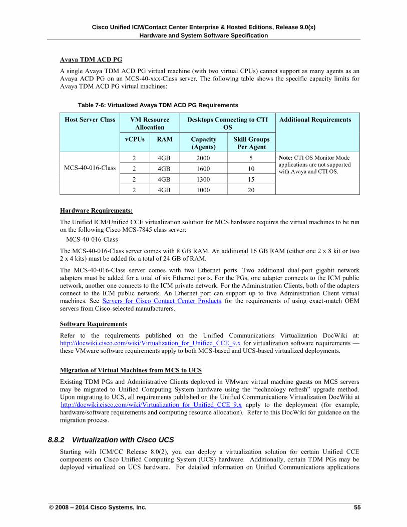
Cisco Unified ICM/Contact Center Enterprise & Hosted Editions, Release 9.0(x)
Hardware and System Software Specification
© 2008 – 2014 Cisco Systems, Inc. 55
Avaya TDM ACD PG
A single Avaya TDM ACD PG virtual machine (with two virtual CPUs) cannot support as many agents as an
Avaya ACD PG on an MCS-40-xxx-Class server. The following table shows the specific capacity limits for
Avaya TDM ACD PG virtual machines:
Table 7-6: Virtualized Avaya TDM ACD PG Requirements
Host Server Class VM Resource
Allocation
Desktops Connecting to CTI
OS
Additional Requirements
vCPUs RAM Capacity
(Agents)
Skill Groups
Per Agent
MCS-40-016-Class
2 4GB 2000 5 Note: CTI OS Monitor Mode
applications are not supported
with Avaya and CTI OS. 2 4GB 1600 10
2 4GB 1300 15
2 4GB 1000 20
Hardware Requirements:
The Unified ICM/Unified CCE virtualization solution for MCS hardware requires the virtual machines to be run
on the following Cisco MCS-7845 class server:
MCS-40-016-Class
The MCS-40-016-Class server comes with 8 GB RAM. An additional 16 GB RAM (either one 2 x 8 kit or two
2 x 4 kits) must be added for a total of 24 GB of RAM.
The MCS-40-016-Class server comes with two Ethernet ports. Two additional dual-port gigabit network
adapters must be added for a total of six Ethernet ports. For the PGs, one adapter connects to the ICM public
network, another one connects to the ICM private network. For the Administration Clients, both of the adapters
connect to the ICM public network. An Ethernet port can support up to five Administration Client virtual
machines. See UServers for Cisco Contact Center ProductsU for the requirements of using exact-match OEM
servers from Cisco-selected manufacturers.
Software Requirements
Refer to the requirements published on the Unified Communications Virtualization DocWiki at:
http://docwiki.cisco.com/wiki/Virtualization_for_Unified_CCE_9.x for virtualization software requirements —
these VMware software requirements apply to both MCS-based and UCS-based virtualized deployments.
Migration of Virtual Machines from MCS to UCS
Existing TDM PGs and Administrative Clients deployed in VMware virtual machine guests on MCS servers
may be migrated to Unified Computing System hardware using the “technology refresh” upgrade method.
Upon migrating to UCS, all requirements published on the Unified Communications Virtualization DocWiki at
UUhttp://docwiki.cisco.com/wiki/Virtualization_for_Unified_CCE_9.x apply to the deployment (for example,
hardware/software requirements and computing resource allocation). Refer to this DocWiki for guidance on the
migration process.
8.8.2 Virtualization with Cisco UCS
Starting with ICM/CC Release 8.0(2), you can deploy a virtualization solution for certain Unified CCE
components on Cisco Unified Computing System (UCS) hardware. Additionally, certain TDM PGs may be
deployed virtualized on UCS hardware. For detailed information on Unified Communications applications
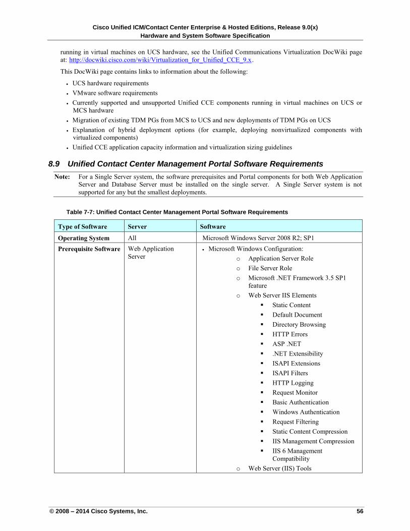
Cisco Unified ICM/Contact Center Enterprise & Hosted Editions, Release 9.0(x)
Hardware and System Software Specification
© 2008 – 2014 Cisco Systems, Inc. 56
running in virtual machines on UCS hardware, see the Unified Communications Virtualization DocWiki page
at: Uhttp://docwiki.cisco.com/wiki/Virtualization_for_Unified_CCE_9.x U.
This DocWiki page contains links to information about the following:
UCS hardware requirements
VMware software requirements
Currently supported and unsupported Unified CCE components running in virtual machines on UCS or
MCS hardware
Migration of existing TDM PGs from MCS to UCS and new deployments of TDM PGs on UCS
Explanation of hybrid deployment options (for example, deploying nonvirtualized components with
virtualized components)
Unified CCE application capacity information and virtualization sizing guidelines
8.9 Unified Contact Center Management Portal Software Requirements
Note: For a Single Server system, the software prerequisites and Portal components for both Web Application
Server and Database Server must be installed on the single server. A Single Server system is not
supported for any but the smallest deployments.
Table 7-7: Unified Contact Center Management Portal Software Requirements
Type of Software Server Software
Operating System All Microsoft Windows Server 2008 R2; SP1
Prerequisite Software Web Application
Server
Microsoft Windows Configuration:
o Application Server Role
o File Server Role
o Microsoft .NET Framework 3.5 SP1
feature
o Web Server IIS Elements
Static Content
Default Document
Directory Browsing
HTTP Errors
ASP .NET
.NET Extensibility
ISAPI Extensions
ISAPI Filters
HTTP Logging
Request Monitor
Basic Authentication
Windows Authentication
Request Filtering
Static Content Compression
IIS Management Compression
IIS 6 Management
Compatibility
o Web Server (IIS) Tools
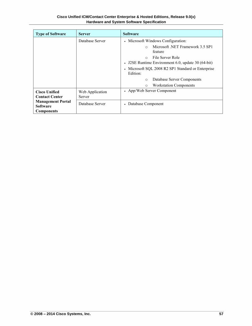
Cisco Unified ICM/Contact Center Enterprise & Hosted Editions, Release 9.0(x)
Hardware and System Software Specification
© 2008 – 2014 Cisco Systems, Inc. 57
Type of Software Server Software
Database Server Microsoft Windows Configuration:
o Microsoft .NET Framework 3.5 SP1
feature
o File Server Role
J2SE Runtime Environment 6.0, update 30 (64-bit)
Microsoft SQL 2008 R2 SP1 Standard or Enterprise
Edition:
o Database Server Components
o Workstation Components
Cisco Unified
Contact Center
Management Portal
Software
Components
Web Application
Server
App/Web Server Component
Database Server Database Component
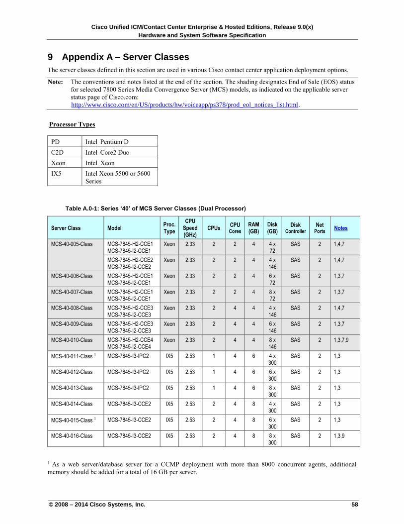
Cisco Unified ICM/Contact Center Enterprise & Hosted Editions, Release 9.0(x)
Hardware and System Software Specification
© 2008 – 2014 Cisco Systems, Inc. 58
9 Appendix A – Server Classes
The server classes defined in this section are used in various Cisco contact center application deployment options.
Note: The conventions and notes listed at the end of the section. The shading designates End of Sale (EOS) status
for selected 7800 Series Media Convergence Server (MCS) models, as indicated on the applicable server
status page of Cisco.com:
Uhttp://www.cisco.com/en/US/products/hw/voiceapp/ps378/prod_eol_notices_list.html U.
10BUProcessor Types
PD Intel Pentium D
C2D Intel Core2 Duo
Xeon Intel Xeon
IX5 Intel Xeon 5500 or 5600
Series
Table A.0-1: Series ‘40’ of MCS Server Classes (Dual Processor)
Server Class Model Proc. Type
CPU Speed (GHz)
CPUs CPU Cores
RAM (GB)
Disk (GB)
Disk Controller
Net Ports
UNotesU
MCS-40-005-Class MCS-7845-H2-CCE1 MCS-7845-I2-CCE1
Xeon 2.33 2 2 4 4 x 72
SAS 2 1,4,7
MCS-7845-H2-CCE2 MCS-7845-I2-CCE2
Xeon 2.33 2 2 4 4 x 146
SAS 2 1,4,7
MCS-40-006-Class MCS-7845-H2-CCE1 MCS-7845-I2-CCE1
Xeon 2.33 2 2 4 6 x 72
SAS 2 1,3,7
MCS-40-007-Class MCS-7845-H2-CCE1 MCS-7845-I2-CCE1
Xeon 2.33 2 2 4 8 x 72
SAS 2 1,3,7
MCS-40-008-Class MCS-7845-H2-CCE3 MCS-7845-I2-CCE3
Xeon 2.33 2 4 4 4 x 146
SAS 2 1,4,7
MCS-40-009-Class MCS-7845-H2-CCE3 MCS-7845-I2-CCE3
Xeon 2.33 2 4 4 6 x 146
SAS 2 1,3,7
MCS-40-010-Class MCS-7845-H2-CCE4 MCS-7845-I2-CCE4
Xeon 2.33 2 4 4 8 x 146
SAS 2 1,3,7,9
MCS-40-011-Class 1 MCS-7845-I3-IPC2 IX5 2.53 1 4 6 4 x 300
SAS 2 1,3
MCS-40-012-Class MCS-7845-I3-IPC2 IX5 2.53 1 4 6 6 x 300
SAS 2 1,3
MCS-40-013-Class MCS-7845-I3-IPC2 IX5 2.53 1 4 6 8 x 300
SAS 2 1,3
MCS-40-014-Class MCS-7845-I3-CCE2 IX5 2.53 2 4 8 4 x 300
SAS 2 1,3
MCS-40-015-Class 1 MCS-7845-I3-CCE2 IX5 2.53 2 4 8 6 x 300
SAS 2 1,3
MCS-40-016-Class MCS-7845-I3-CCE2 IX5 2.53 2 4 8 8 x 300
SAS 2 1,3,9
1 As a web server/database server for a CCMP deployment with more than 8000 concurrent agents, additional
memory should be added for a total of 16 GB per server.
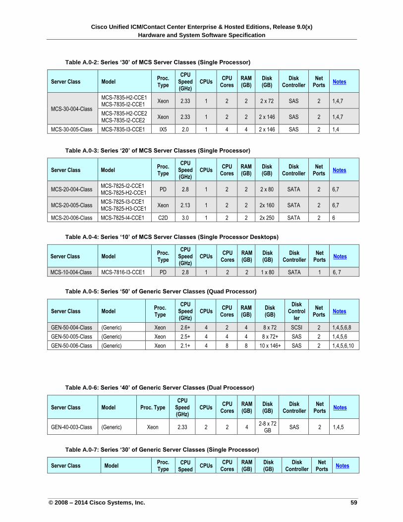
Cisco Unified ICM/Contact Center Enterprise & Hosted Editions, Release 9.0(x)
Hardware and System Software Specification
© 2008 – 2014 Cisco Systems, Inc. 59
Table A.0-2: Series ‘30’ of MCS Server Classes (Single Processor)
Server Class Model Proc. Type
CPU Speed (GHz)
CPUs CPU
Cores RAM (GB)
Disk (GB)
Disk Controller
Net Ports
UNotesU
MCS-30-004-Class
MCS-7835-H2-CCE1 MCS-7835-I2-CCE1
Xeon 2.33 1 2 2 2 x 72 SAS 2 1,4,7
MCS-7835-H2-CCE2 MCS-7835-I2-CCE2
Xeon 2.33 1 2 2 2 x 146 SAS 2 1,4,7
MCS-30-005-Class MCS-7835-I3-CCE1 IX5 2.0 1 4 4 2 x 146 SAS 2 1,4
Table A.0-3: Series ‘20’ of MCS Server Classes (Single Processor)
Server Class Model Proc. Type
CPU Speed (GHz)
CPUs CPU
Cores RAM (GB)
Disk (GB)
Disk Controller
Net Ports
UNotesU
MCS-20-004-Class MCS-7825-I2-CCE1 MCS-7825-H2-CCE1
PD 2.8 1 2 2 2 x 80 SATA 2 6,7
MCS-20-005-Class MCS-7825-I3-CCE1 MCS-7825-H3-CCE1
Xeon 2.13 1 2 2 2x 160 SATA 2 6,7
MCS-20-006-Class MCS-7825-I4-CCE1 C2D 3.0 1 2 2 2x 250 SATA 2 6
Table A.0-4: Series ‘10’ of MCS Server Classes (Single Processor Desktops)
Server Class Model Proc. Type
CPU Speed (GHz)
CPUs CPU
Cores RAM (GB)
Disk (GB)
Disk Controller
Net Ports
UNotesU
MCS-10-004-Class MCS-7816-I3-CCE1 PD 2.8 1 2 2 1 x 80 SATA 1 6, 7
Table A.0-5: Series ‘50’ of Generic Server Classes (Quad Processor)
Server Class Model Proc. Type
CPU Speed (GHz)
CPUs CPU
Cores RAM (GB)
Disk (GB)
Disk Control
ler
Net Ports
UNotesU
GEN-50-004-Class (Generic) Xeon 2.6+ 4 2 4 8 x 72 SCSI 2 1,4,5,6,8
GEN-50-005-Class (Generic) Xeon 2.5+ 4 4 4 8 x 72+ SAS 2 1,4,5,6
GEN-50-006-Class (Generic) Xeon 2.1+ 4 8 8 10 x 146+ SAS 2 1,4,5,6,10
Table A.0-6: Series ‘40’ of Generic Server Classes (Dual Processor)
Server Class Model Proc. Type CPU
Speed (GHz)
CPUs CPU
Cores RAM (GB)
Disk (GB)
Disk Controller
Net Ports
UNotesU
GEN-40-003-Class (Generic) Xeon 2.33 2 2 4 2-8 x 72
GB SAS 2 1,4,5
Table A.0-7: Series ‘30’ of Generic Server Classes (Single Processor)
Server Class Model Proc. Type
CPU Speed
CPUs CPU
Cores RAM (GB)
Disk (GB)
Disk Controller
Net Ports
UNotesU
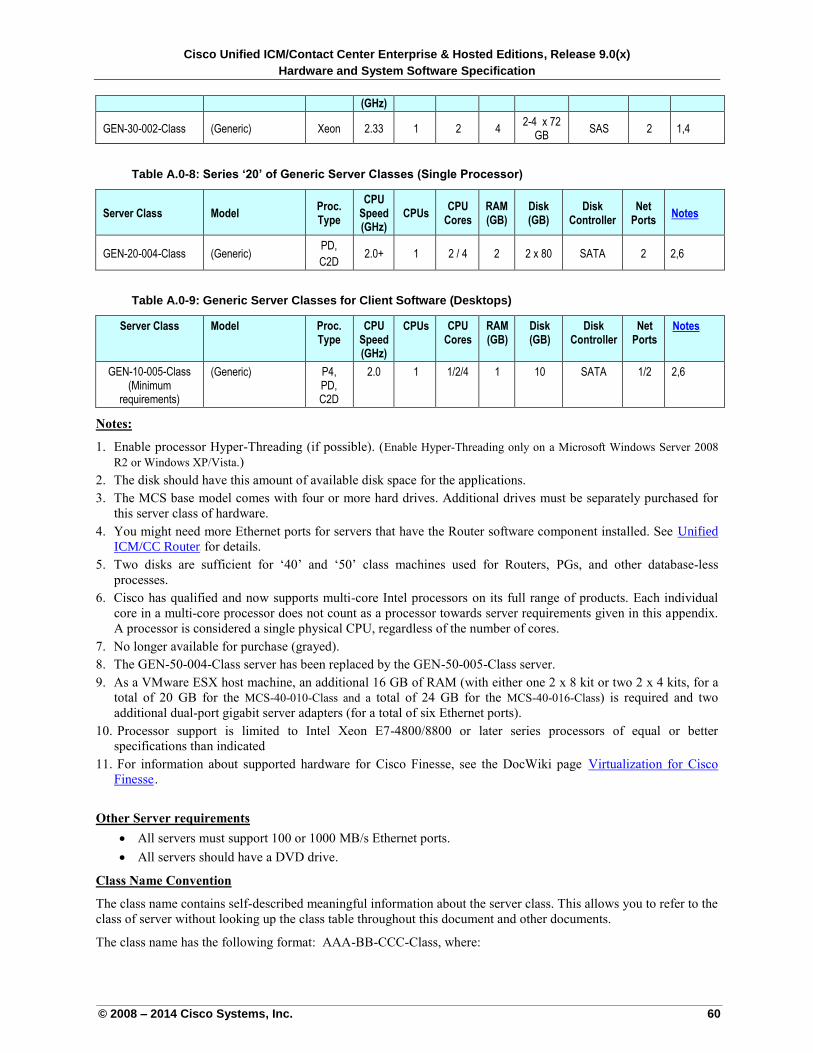
Cisco Unified ICM/Contact Center Enterprise & Hosted Editions, Release 9.0(x)
Hardware and System Software Specification
© 2008 – 2014 Cisco Systems, Inc. 60
(GHz)
GEN-30-002-Class (Generic) Xeon 2.33 1 2 4 2-4 x 72
GB SAS 2 1,4
Table A.0-8: Series ‘20’ of Generic Server Classes (Single Processor)
Server Class Model Proc. Type
CPU Speed (GHz)
CPUs CPU
Cores RAM (GB)
Disk (GB)
Disk Controller
Net Ports
UNotesU
GEN-20-004-Class (Generic) PD,
C2D 2.0+ 1 2 / 4 2 2 x 80 SATA 2 2,6
Table A.0-9: Generic Server Classes for Client Software (Desktops)
Server Class Model Proc. Type
CPU Speed (GHz)
CPUs CPU Cores
RAM (GB)
Disk (GB)
Disk Controller
Net Ports
UNotesU
GEN-10-005-Class (Minimum
requirements)
(Generic) P4, PD, C2D
2.0 1 1/2/4 1 10 SATA 1/2 2,6
Notes:
1. Enable processor Hyper-Threading (if possible). (Enable Hyper-Threading only on a Microsoft Windows Server 2008
R2 or Windows XP/Vista.)
2. The disk should have this amount of available disk space for the applications.
3. The MCS base model comes with four or more hard drives. Additional drives must be separately purchased for
this server class of hardware.
4. You might need more Ethernet ports for servers that have the Router software component installed. See UUnified
ICM/CC RouterU for details.
5. Two disks are sufficient for ‘40’ and ‘50’ class machines used for Routers, PGs, and other database-less
processes.
6. Cisco has qualified and now supports multi-core Intel processors on its full range of products. Each individual
core in a multi-core processor does not count as a processor towards server requirements given in this appendix.
A processor is considered a single physical CPU, regardless of the number of cores.
7. No longer available for purchase (grayed).
8. The GEN-50-004-Class server has been replaced by the GEN-50-005-Class server.
9. As a VMware ESX host machine, an additional 16 GB of RAM (with either one 2 x 8 kit or two 2 x 4 kits, for a
total of 20 GB for the MCS-40-010-Class and a total of 24 GB for the MCS-40-016-Class) is required and two
additional dual-port gigabit server adapters (for a total of six Ethernet ports).
10. Processor support is limited to Intel Xeon E7-4800/8800 or later series processors of equal or better
specifications than indicated
11. For information about supported hardware for Cisco Finesse, see the DocWiki page UVirtualization for Cisco
FinesseU.
Other Server requirements
All servers must support 100 or 1000 MB/s Ethernet ports.
All servers should have a DVD drive.
Class Name Convention
The class name contains self-described meaningful information about the server class. This allows you to refer to the
class of server without looking up the class table throughout this document and other documents.
The class name has the following format: AAA-BB-CCC-Class, where:
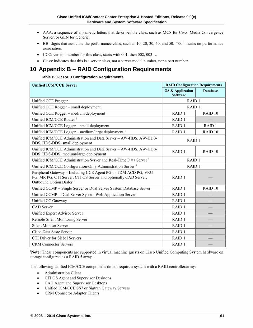
Cisco Unified ICM/Contact Center Enterprise & Hosted Editions, Release 9.0(x)
Hardware and System Software Specification
© 2008 – 2014 Cisco Systems, Inc. 61
AAA: a sequence of alphabetic letters that describes the class, such as MCS for Cisco Media Convergence
Server, or GEN for Generic.
BB: digits that associate the performance class, such as 10, 20, 30, 40, and 50. “00” means no performance
association.
CCC: version number for this class, starts with 001, then 002, 003 …
Class: indicates that this is a server class, not a server model number, nor a part number.
10 Appendix B – RAID Configuration Requirements
Table B.0-1: RAID Configuration Requirements
Unified ICM/CCE Server RAID Configuration Requirements
OS & Application
Software
Database
Unified CCE Progger RAID 1
Unified CCE Rogger – small deployment RAID 1
Unified CCE Rogger – medium deployment 1 RAID 1 RAID 10
Unified ICM/CCE Router 1 RAID 1 —
Unified ICM/CCE Logger – small deployment RAID 1 RAID 1
Unified ICM/CCE Logger – medium/large deployment 1 RAID 1 RAID 10
Unified ICM/CCE Administration and Data Server – AW-HDS, AW-HDS-
DDS, HDS-DDS; small deployment RAID 1
Unified ICM/CCE Administration and Data Server – AW-HDS, AW-HDS-
DDS, HDS-DDS; medium/large deployment RAID 1 RAID 10
Unified ICM/CCE Administration Server and Real-Time Data Server 1 RAID 1
Unified ICM/CCE Configuration-Only Administration Server 1 RAID 1
Peripheral Gateway – Including CCE Agent PG or TDM ACD PG, VRU
PG, MR PG, CTI Server, CTI OS Server and optionally CAD Server,
Outbound Option Dialer 1
RAID 1 —
Unified CCMP – Single Server or Dual Server System Database Server RAID 1 RAID 10
Unified CCMP – Dual Server System Web Application Server RAID 1 —
Unified CC Gateway RAID 1 —
CAD Server RAID 1 —
Unified Expert Advisor Server RAID 1 —
Remote Silent Monitoring Server RAID 1 —
Silent Monitor Server RAID 1 —
Cisco Data Store Server RAID 1 —
CTI Driver for Siebel Servers RAID 1 —
CRM Connector Servers RAID 1 —
1Note: These components are supported in virtual machine guests on Cisco Unified Computing System hardware on
storage configured as a RAID 5 array.
The following Unified ICM/CCE components do not require a system with a RAID controller/array:
Administration Client
CTI OS Agent and Supervisor Desktops
CAD Agent and Supervisor Desktops
Unified ICM/CCE SS7 or Sigtran Gateway Servers
CRM Connector Adapter Clients
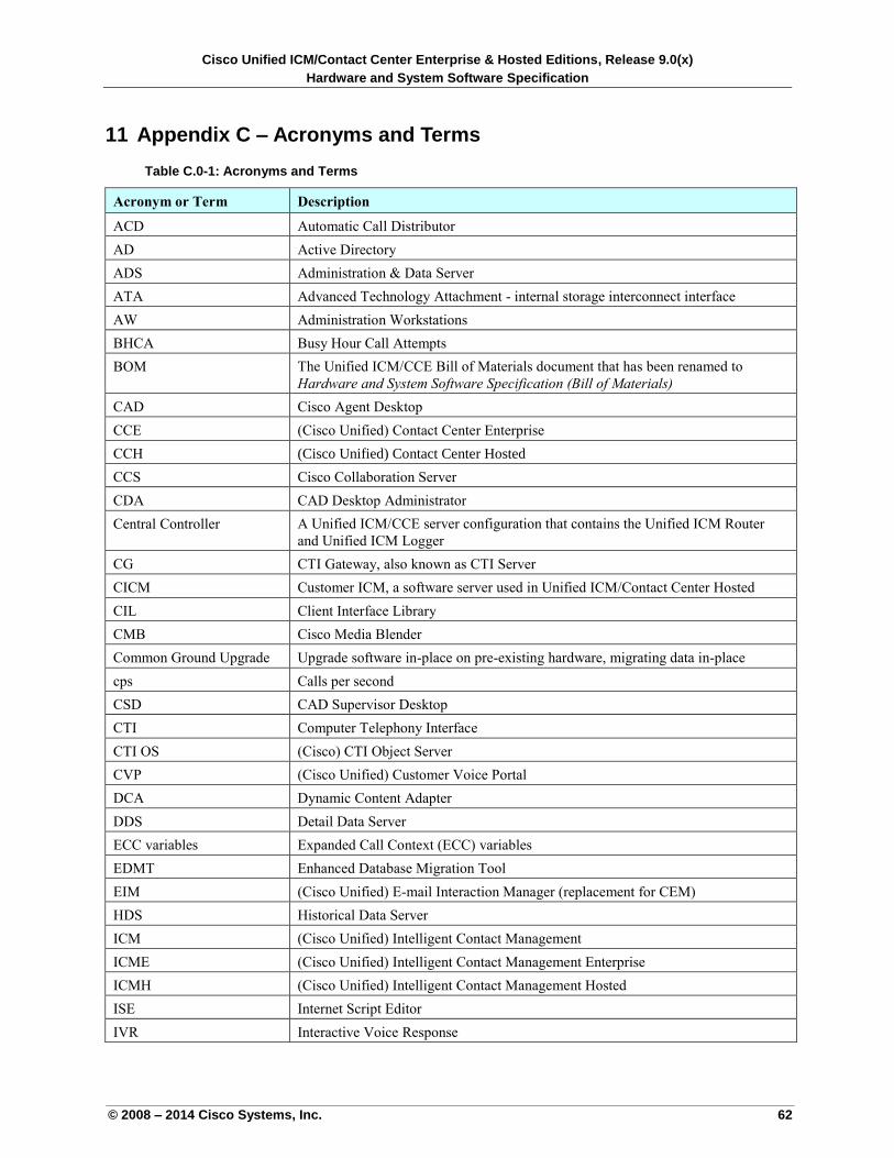
Cisco Unified ICM/Contact Center Enterprise & Hosted Editions, Release 9.0(x)
Hardware and System Software Specification
© 2008 – 2014 Cisco Systems, Inc. 62
11 Appendix C – Acronyms and Terms
Table C.0-1: Acronyms and Terms
Acronym or Term Description
ACD Automatic Call Distributor
AD Active Directory
ADS Administration & Data Server
ATA Advanced Technology Attachment - internal storage interconnect interface
AW Administration Workstations
BHCA Busy Hour Call Attempts
BOM The Unified ICM/CCE Bill of Materials document that has been renamed to
Hardware and System Software Specification (Bill of Materials)
CAD Cisco Agent Desktop
CCE (Cisco Unified) Contact Center Enterprise
CCH (Cisco Unified) Contact Center Hosted
CCS Cisco Collaboration Server
CDA CAD Desktop Administrator
Central Controller A Unified ICM/CCE server configuration that contains the Unified ICM Router
and Unified ICM Logger
CG CTI Gateway, also known as CTI Server
CICM Customer ICM, a software server used in Unified ICM/Contact Center Hosted
CIL Client Interface Library
CMB Cisco Media Blender
Common Ground Upgrade Upgrade software in-place on pre-existing hardware, migrating data in-place
cps Calls per second
CSD CAD Supervisor Desktop
CTI Computer Telephony Interface
CTI OS (Cisco) CTI Object Server
CVP (Cisco Unified) Customer Voice Portal
DCA Dynamic Content Adapter
DDS Detail Data Server
ECC variables Expanded Call Context (ECC) variables
EDMT Enhanced Database Migration Tool
EIM (Cisco Unified) E-mail Interaction Manager (replacement for CEM)
HDS Historical Data Server
ICM (Cisco Unified) Intelligent Contact Management
ICME (Cisco Unified) Intelligent Contact Management Enterprise
ICMH (Cisco Unified) Intelligent Contact Management Hosted
ISE Internet Script Editor
IVR Interactive Voice Response
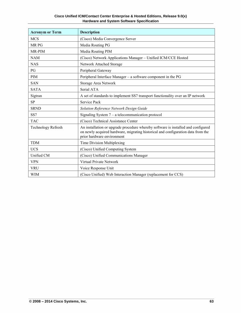
Cisco Unified ICM/Contact Center Enterprise & Hosted Editions, Release 9.0(x)
Hardware and System Software Specification
© 2008 – 2014 Cisco Systems, Inc. 63
Acronym or Term Description
MCS (Cisco) Media Convergence Server
MR PG Media Routing PG
MR-PIM Media Routing PIM
NAM (Cisco) Network Applications Manager – Unified ICM/CCE Hosted
NAS Network Attached Storage
PG Peripheral Gateway
PIM Peripheral Interface Manager – a software component in the PG
SAN Storage Area Network
SATA Serial ATA
Sigtran A set of standards to implement SS7 transport functionality over an IP network
SP Service Pack
SRND Solution Reference Network Design Guide
SS7 Signaling System 7 – a telecommunication protocol
TAC (Cisco) Technical Assistance Center
Technology Refresh An installation or upgrade procedure whereby software is installed and configured
on newly acquired hardware, migrating historical and configuration data from the
prior hardware environment
TDM Time Division Multiplexing
UCS (Cisco) Unified Computing System
Unified CM (Cisco) Unified Communications Manager
VPN Virtual Private Network
VRU Voice Response Unit
WIM (Cisco Unified) Web Interaction Manager (replacement for CCS)