HARBEN CENTURY PUMP SERVICE MANUALharben.com/.../12/COMPRESSED_Century_Manual_-Issue-6.pdf ·...
80
HARBEN CENTURY PUMP SERVICE MANUAL This manual contains IMPORTANT Safety Information Part No. 061357 Flowplant Group Ltd Issue 6 November 2016
Transcript of HARBEN CENTURY PUMP SERVICE MANUALharben.com/.../12/COMPRESSED_Century_Manual_-Issue-6.pdf ·...
HARBEN
CENTURY PUMP
SERVICE MANUAL
This manual contains
IMPORTANT Safety Information
Part No. 061357
Flowplant Group Ltd Issue 6 November 2016
FLOWPLANT
AMENDMENTS
CENTURY PUMP SERVICE MANUAL
AMENDMENTS
Change Number
Page(s) Amended Date Signature
5 Re-formatted 05/16 TWC
5.2 Warranty section amended 10/16 GHM
6 Re-formatted / Health & Safety section amended
28/11 AC
HARBEN
CENTURY TYPE PUMP
SERVICE MANUAL
Contents
Section Page
FOREWORD 2 HEALTH AND SAFETY AT WORK 3 SECTION 1 PUMP TECHNICAL DATA 11 SECTION 2 PUMP INSTALLATION 22 SECTION 3 GENERAL OPERATING INFORMATION 29 SECTION 4 PUMP MAINTENANCE AND OVERHAUL PROCEDURES 44 SECTION 5 WARRANTY 72
A detailed contents list precedes each section
FLOWPLANT
1
Flowplant Century Pump Manual
FOREWORD
This manual is primarily concerned with the Harben Century Type Pump. In addition,
general safety and operating information for the equipment into which the pump is
installed is also included.
The conversion of pressurised water into a high velocity jet and its use as a cleaning
and cutting tool is now familiar to, and used by, many people in a wide range of
industries.
High pressure water can achieve remarkable results without the use of heat or
chemicals and cost savings over conventional maintenance methods can in many
cases show that a water jetting unit will pay for itself in hours rather than years.
Many companies have problems for which high pressure water offers a rapid
solution, yet hesitate to consider this method because of the generally accepted high
cost of such equipment. Backed by many years of design and manufacturing
experience, Harben pumps are setting new standards of performance and reliability.
The capital and operating costs are such that these offer and attractive return on
investment that really makes sense.
Flowplant Group Ltd have a policy of continual research and improvement and we
reserve the right to make such modifications and design changes as are considered
necessary in the light of experience, however, this copy of the manual will not be
amended.
No part of this manual may be reproduced or copied in any manner without written
permission from Flowplant Group Ltd.
FLOWPLANT
2
Flowplant Century Pump Manual
HEALTH AND SAFETY AT WORK There are two main categories of risk. These are:
a) Injury from impact of water
b) Injury from environment.
All persons involved in water jetting should be made aware of the risks.
INJURY FROM IMPACT OF WATER
In the event that a person is injured by the impact of a water jet, the injury caused
may appear insignificant and give little indication of the extent of the injury beneath
the skin and the damage to deeper tissues. Large quantities of water may have
punctured the skin, flesh and organs through a very small hole that may not even
bleed.
Immediate hospital attention is required and medical staff must be informed of the
cause of the injury. To ensure that this is not overlooked, all operators engaged on
jetting should carry an immediately accessible waterproof card which outlines the
possible nature of the injury and bears the following text which has been endorsed
by the Employment Medical Advisory Service (EMAS) of the Health and Safety
Executive:
Please take this into account when making your diagnosis. Unusual infections with
micro-aerophilic organisms occurring at lower temperatures have been reported.
These may have gram negative pathogens such as are found in sewage. Bacterial
swabs and blood cultures may therefore be helpful.
A letter containing this and other relevant information should be sent to the doctor of
each operator.
Where surgical examination is not immediately possible in remote situations, first aid
measures should be confined to dressing the wound and observing the patient
closely until a medical examination has been arranged.
THIS MAN HAS BEEN INVOLVED WITH HIGH PRESSURE WATER JETTING
AT PRESSURE UP TO 36750 LB/IN2 (250 MPA, 2500 BAR, 2548 KG/CM2)
WITH A JET VELOCITY OF 1536 MILES (2458 KM) PER HOUR.
FLOWPLANT
3
Flowplant Century Pump Manual
If any person, object or article is accidentally struck by the jet, this fact must be
reported to the operator's representative.
INJURY FROM ENVIRONMENT
Work should only be carried out if it is safe to do so. A thorough examination of the
site should be carried out before work is started. Refer to the Warnings and
Cautions.
Special care should be taken where there is a danger of infection. There are many
situations where infection can take place. As a guide to avoiding infection, the
following points should be considered:
a) Full protective clothing must be worn.
b) Always clean scratches or cuts immediately. Disinfect and cover with a strip of
gauze and impermeable plaster. SEEK MEDICAL HELP.
c) Avoid rubbing eyes, nose or mouth with hands during working.
d) All contaminated clothing, vehicles and equipment should be thoroughly
cleaned.
e) Operators should wash thoroughly after work and before eating, drinking or
smoking.
FLOWPLANT
4
Flowplant Century Pump Manual
SAFETY CODE OF PRACTICE
Full details of the Safety Code of Practice, when working with equipment containing
a Harben pump, are given in Section 3 of this manual. The basic rules of this code
are as follows:
1. ALWAYS WEAR THE CORRECT PROTECTIVE CLOTHING.
2. ALWAYS ENSURE ALL EQUIPMENT IS IN A FIRST CLASS CONDITION.
3. NEVER WORK FROM A LADDER.
4. NEVER USE THE GUN WITH THE TRIGGER LOCKED ON.
5. NEVER POINT THE GUN AT ANYONE, EVEN IF SWITCHED OFF.
Only a responsible person who has received instruction in the operation of high
pressure water jetting equipment should be allowed to operate the equipment.
FLOWPLANT
5
Flowplant Century Pump Manual
POTENTIAL HAZARDS AND MISUSE OF HIGH PRESSURE EQUIPMENT
Never use a jetter that isn’t regularly serviced according to the manufacturer’s
recommendations.
When a jetter is used to clean drains & sewers that are contaminated with a
hazardous substance it is possible these may be entrained in the resulting
aerosol and inhaled by operators. Consider using respiratory protection.
Do not spray flammable liquids – there is a risk of
explosion.
Ensure the correct fuel is used on all occasions or there
is a risk of explosion.
Never start the jetter when frozen. Operating a jetter whilst frozen could cause
high speed ice bullets to be ejected from the jetter hose on machine start up.
Never start jetting a drain, sewer or pipe unless the jet nozzle is safely inside the drain and pointing in the direction that you intend it to travel.
When drain jetting a drain, sewer or pipe with an inside diameter that is not small enough to prevent the hose from turning back on itself, a drain jet extension (a piece of straight rigid tube equivalent to the pipe diameter) should be fitted between the end of the hose and the nozzle.
Always use a safety leader hose at the beginning of the main jetting hose to alert operators when the jet nozzle is nearing the manhole entrance.
Always consider the use of a tiger tail hose feed guide to protect the jetting hose from abrasion and prevent premature failure.
Be aware that high pressure hoses can generate static electricity which may
need to be controlled when working in hazardous areas.
Never direct a high pressure water jet at electric power lines or electrical equipment as serious injury or death from electrocution could occur.
When jetting drains or sewers if there is a danger to the general public from hoses laying across public walkways they must be covered in such a way as to protect against injury from hose failure and tripping hazards.
Failure to follow the instructions where
this icon is shown can result in serious
injury or even death
FLOWPLANT
6
Flowplant Century Pump Manual
POTENTIAL HAZARDS AND MISUSE OF HIGH PRESSURE EQUIPMENT
Before starting work, check and ensure the drain jets have no blocked holes or nozzles as this may cause the pumping system to over pressurise which could result in burst disc failure or bursting the jetting hose.
Never attempt to unblock a fully choked drain or pipe before considering the consequence of releasing the blockage and having a plan to deal with it. E.g. flooding, material ejection, drain nozzle ejection.
Never attempt to clean drains or pipes in one pass because this could lead to debris build up behind the jet nozzle causing a pressure build up in the drainage system. Be aware that a pressure build up in the drain or pipe could cause the jet nozzle to be ejected at speed back towards the operator.
Never enter the manhole to either place the jet nozzle into or extract it from the drain entrance unless the required confined space regulations have been met.
Never work in a manhole with a radio remote control transmitter that is not
classified for use in such areas.
Never use the hydraulic hose reel facility as a winch to retract a jetting hose that has become stuck in the drain or pipe. Damage to the hose could be caused that will make subsequent hose failure more likely.
Never allow jetting hoses to become kinked and always remove from service any jetting hose with an outer cover that has worn through to the reinforcing braid.
Never use the high pressure jetting hose for any purpose other than sewer, drain or pipe cleaning, e.g. winching vehicles or other plant.
Never use jetting nozzles and/or accessories that have not been calibrated for the jetting machine pump performance as this could cause rapid over pressurisation catching operators unaware.
Never attempt to clean a drain or pipe with a nozzle that has more forward force than rear force. It could be ejected back toward the operator causing injury.
Never attempt to clean a drain or pipe with a chain flail type jet that has unequal chain lengths as this could lead to severe vibration and high pressure hose failure.
Failure to follow the instructions where this
icon is shown can result in serious injury
or even death
FLOWPLANT
7
Flowplant Century Pump Manual
POTENTIAL HAZARDS AND MISUSE OF HIGH PRESSURE EQUIPMENT
When using a venturi jet pump to remove fluid from a flooded manhole never place your fingers into the pump inlet as they could be trapped by the vacuum and cause injury.
When using a venturi jet pump to remove fluid from a flooded manhole always secure the free end of the pump hose securely and ensure adequate drainage is in place to deal with high volumes of pumped water.
Never use a dry shut type foot control valve on a jetter that does not have a pressure unloader valve as this could result in burst disc failure or bursting the jetting hose.
When using a dry shut type system be aware that high pressure can be retained in the jetting hose even after the machine has been shut down. Always discharge pressure in a safe manner after machine shut down.
When working with a gun always consider using a safety shroud to provide
the operator with greater protection in the event of a hose burst.
Never point the gun at anyone as injury from high pressure water will occur if the jet stream comes into contact with body parts.
Never work on a slippery surface because the reaction force of the jetting gun could cause you to become unstable and lose your footing.
Never work from a ladder as the reaction force of the jetting gun could cause the ladder to fall backwards from the working area causing possible injury.
Never work from scaffolding unless it is designed, erected and managed by competent persons and it is adequately secured to prevent it being pushed over by jetting gun reaction forces.
When using the jetting gun to clean hard surfaces be aware that splash back could contain hard debris travelling at speed.
When using the jetting gun to clean contaminated surfaces be aware that splash back could contain dangerous contaminants.
Never use the jetting gun to clean a surface that could be damage or penetrated by the water pressure unless that is the desired effect.
Failure to follow the instructions where this
icon is shown can result in serious injury
or even death
FLOWPLANT
8
Flowplant Century Pump Manual
POTENTIAL HAZARDS AND MISUSE OF HIGH PRESSURE EQUIPMENT
Always ensure that an adequate area is cordoned off around the working zone so that flying debris and contamination cannot injure passers-by.
Be aware that the use of water jetting guns fitted with oscillating or rotating heads tend to produce higher hand arm vibration levels than simple fixed head jets.
When using a jetting gun or nozzle to clean at floor level wear suitable protective foot wear.
Never use a high pressure jetting gun to clean down PPE whilst you or others are still wearing it as serious injury and death could result.
Never use a high pressure jetting gun to wash or cool down livestock as serious injury and death could result.
Drainage systems may carry bacteria and micro-organisms which can cause severe illness or death. Avoid exposing eyes, nose, mouth, ears, hands, cuts or abrasions to waste water or faecal matter during drain cleaning operations. After working around drainage systems help protect yourself by always washing hands.
Failure to follow the instructions where this
icon is shown can result in serious injury
or even death
FLOWPLANT
9
Flowplant Century Pump Manual
PERSONAL PROTECTIVE EQUIPMENT (PPE) All persons using high pressure water jetting equipment should use all necessary PPE suitable for the task being carried out. This includes, but is not limited to:
Ear protection
Eye protection: a helmet with chin guard and visor is recommended
Hand protection
Waterproof clothing
Safety boots with toe protection Please note: A site specific Risk Assessment / Job Hazard Analysis must be completed to analyse which PPE must be worn.
FLOWPLANT
10
Section 1
Pump Technical Data
FLOWPLANT
11
Section 1
Technical Data
Contents
Section Page
1.1 Introduction 13
1.2 Pump Description 14
1.2.1 Function 14
1.2.2 Filtration 14
1.2.3 Fluid Flow 14
1.3 Identity 15
1.3.1 Manufacturer 15
1.3.2 Pump Operation / Identification 15
1.4 Design and Performance Data 16
1.4.1 Physical Data 16
1.4.2 Performance Characteristics 16
1.5 Equipment Details 17
1.6 Associated Publications 17
Illustration
Fig Page
1.1 Pump General arrangement 18
1.2 Performance Data Litres 19
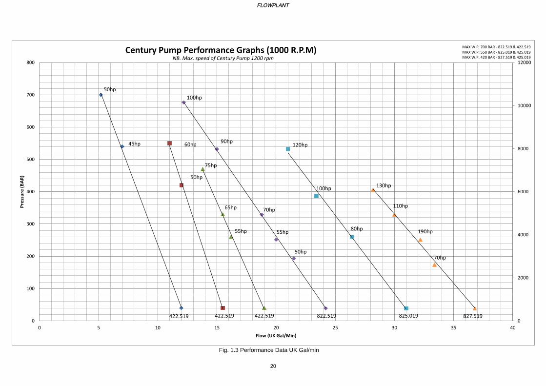
1.3 Performance Data Gallons 20
Tables
Table Page
1.1 Pump Physical Data 16
1.2 Pump Performance Data 16
FLOWPLANT
12
Flowplant Century Pump Manual
1.1 INTRODUCTION
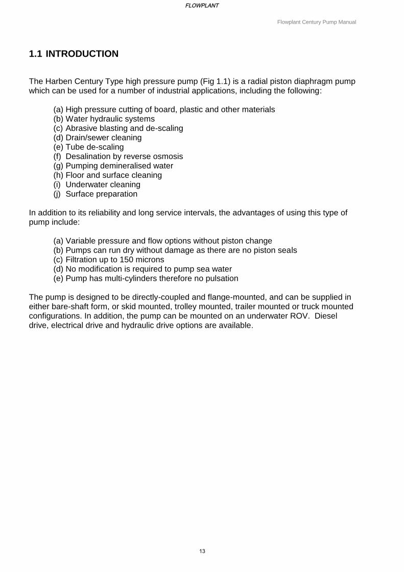
The Harben Century Type high pressure pump (Fig 1.1) is a radial piston diaphragm pump which can be used for a number of industrial applications, including the following:
(a) High pressure cutting of board, plastic and other materials (b) Water hydraulic systems (c) Abrasive blasting and de-scaling (d) Drain/sewer cleaning (e) Tube de-scaling (f) Desalination by reverse osmosis (g) Pumping demineralised water (h) Floor and surface cleaning (i) Underwater cleaning (j) Surface preparation
In addition to its reliability and long service intervals, the advantages of using this type of pump include:
(a) Variable pressure and flow options without piston change (b) Pumps can run dry without damage as there are no piston seals (c) Filtration up to 150 microns (d) No modification is required to pump sea water (e) Pump has multi-cylinders therefore no pulsation
The pump is designed to be directly-coupled and flange-mounted, and can be supplied in either bare-shaft form, or skid mounted, trolley mounted, trailer mounted or truck mounted configurations. In addition, the pump can be mounted on an underwater ROV. Diesel drive, electrical drive and hydraulic drive options are available.
FLOWPLANT
13
Flowplant Century Pump Manual
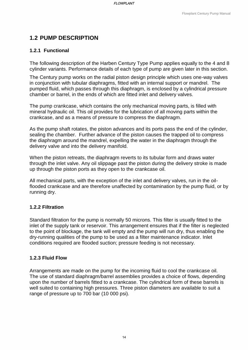
1.2 PUMP DESCRIPTION
1.2.1 Functional
The following description of the Harben Century Type Pump applies equally to the 4 and 8 cylinder variants. Performance details of each type of pump are given later in this section.
The Century pump works on the radial piston design principle which uses one-way valves in conjunction with tubular diaphragms, fitted with an internal support or mandrel. The pumped fluid, which passes through this diaphragm, is enclosed by a cylindrical pressure chamber or barrel, in the ends of which are fitted inlet and delivery valves. The pump crankcase, which contains the only mechanical moving parts, is filled with mineral hydraulic oil. This oil provides for the lubrication of all moving parts within the crankcase, and as a means of pressure to compress the diaphragm.
As the pump shaft rotates, the piston advances and its ports pass the end of the cylinder, sealing the chamber. Further advance of the piston causes the trapped oil to compress the diaphragm around the mandrel, expelling the water in the diaphragm through the delivery valve and into the delivery manifold. When the piston retreats, the diaphragm reverts to its tubular form and draws water through the inlet valve. Any oil slippage past the piston during the delivery stroke is made up through the piston ports as they open to the crankcase oil. All mechanical parts, with the exception of the inlet and delivery valves, run in the oil-flooded crankcase and are therefore unaffected by contamination by the pump fluid, or by running dry.
1.2.2 Filtration
Standard filtration for the pump is normally 50 microns. This filter is usually fitted to the inlet of the supply tank or reservoir. This arrangement ensures that if the filter is neglected to the point of blockage, the tank will empty and the pump will run dry, thus enabling the dry-running qualities of the pump to be used as a filter maintenance indicator. Inlet conditions required are flooded suction; pressure feeding is not necessary.
1.2.3 Fluid Flow
Arrangements are made on the pump for the incoming fluid to cool the crankcase oil. The use of standard diaphragm/barrel assemblies provides a choice of flows, depending upon the number of barrels fitted to a crankcase. The cylindrical form of these barrels is well suited to containing high pressures. Three piston diameters are available to suit a range of pressure up to 700 bar (10 000 psi).
FLOWPLANT
14

Flowplant Century Pump Manual
1.3 IDENTITY
1.3.1 Manufacturer
The Harben Pumps are manufactured by:
Flowplant Group Ltd., Gemini House, Brunel Road,
Churchfields Industrial Estate, Salisbury, Wiltshire, SP2 7PU, ENGLAND
Tel: +44 (0)1722 325 424 Fax: +44 (0)1722 411 329
www.flowplant.com [email protected]
1.3.2 Pump Options/Identification
The Century Pump is available in either 4 or 8 cylinder options, with each having a choice of piston/cylinder diameter options of 22.5 mm, 25.0 mm or 27.5 mm. All barrels are given a letter code to indicate their position in the crankcase (refer to Section 4, Fig 4.2). This letter code can be found stamped on the face adjacent the inner cylinder. Letters A to H are used. Each barrel of a different code is given its own part number.
A pump specification label is fitted on the pump crankcase, adjacent to the oil filler cap.
This label will give the pump type, ie number of cylinders and piston/cylinder diameter.
For example:
8 22.5
no. of cyl piston dia.
The label also gives the pump serial number, the type of oil to be used (Shell Tellus or equivalent), the maximum working pressure, the maximum working flow, and the pump's year of manufacture.
FLOWPLANT
15
Flowplant Century Pump Manual
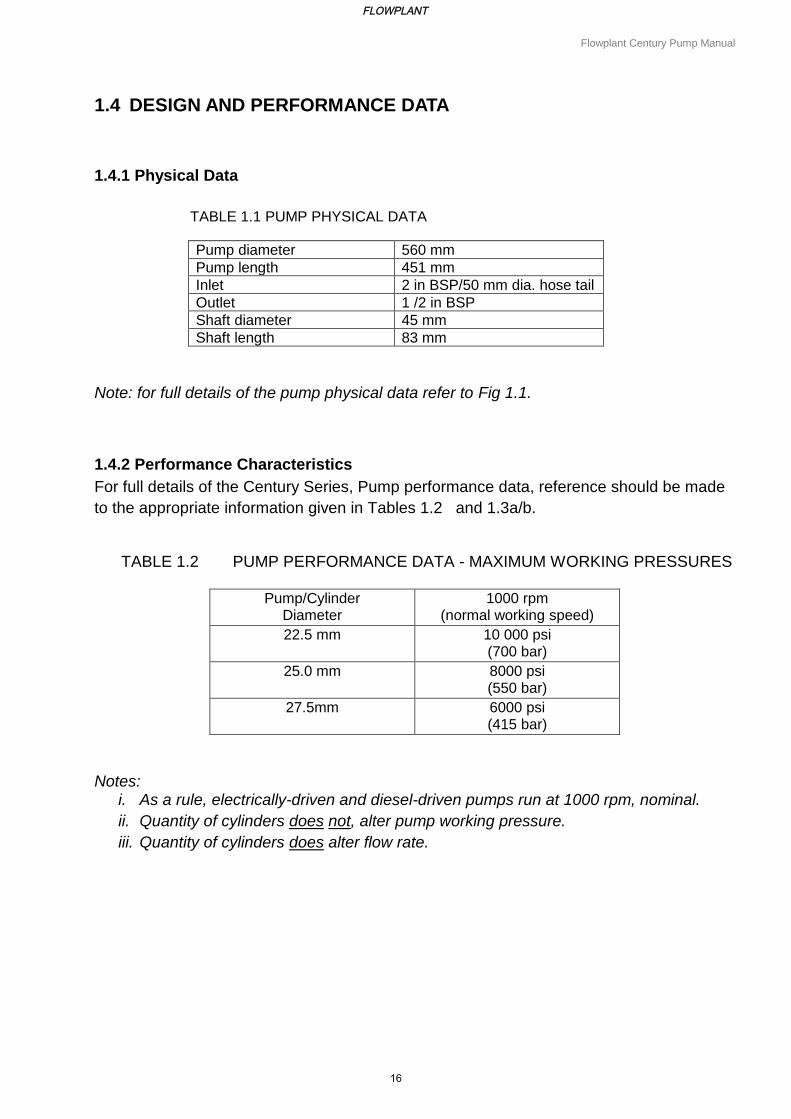
1.4 DESIGN AND PERFORMANCE DATA
1.4.1 Physical Data
TABLE 1.1 PUMP PHYSICAL DATA
Pump diameter 560 mm
Pump length 451 mm
Inlet 2 in BSP/50 mm dia. hose tail
Outlet 1 /2 in BSP
Shaft diameter 45 mm
Shaft length 83 mm
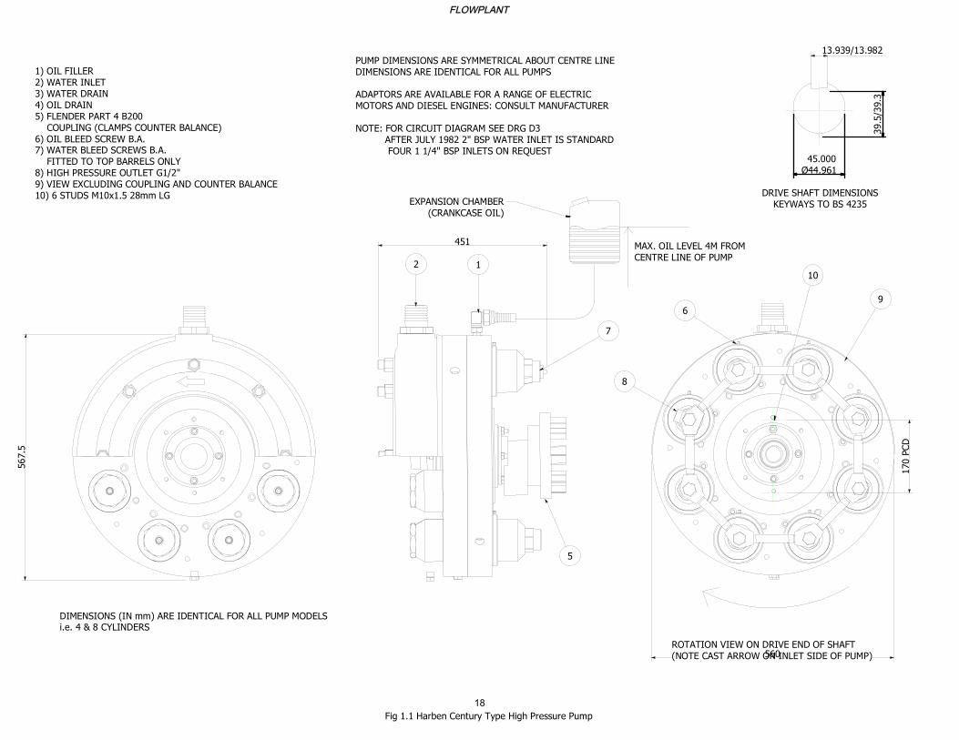
Note: for full details of the pump physical data refer to Fig 1.1.
1.4.2 Performance Characteristics
For full details of the Century Series, Pump performance data, reference should be made
to the appropriate information given in Tables 1.2 and 1.3a/b.
TABLE 1.2 PUMP PERFORMANCE DATA - MAXIMUM WORKING PRESSURES
Pump/Cylinder Diameter
1000 rpm (normal working speed)
22.5 mm 10 000 psi (700 bar)
25.0 mm 8000 psi (550 bar)
27.5mm 6000 psi (415 bar)
Notes:
i. As a rule, electrically-driven and diesel-driven pumps run at 1000 rpm, nominal.
ii. Quantity of cylinders does not, alter pump working pressure.
iii. Quantity of cylinders does alter flow rate.
FLOWPLANT
16
Flowplant Century Pump Manual
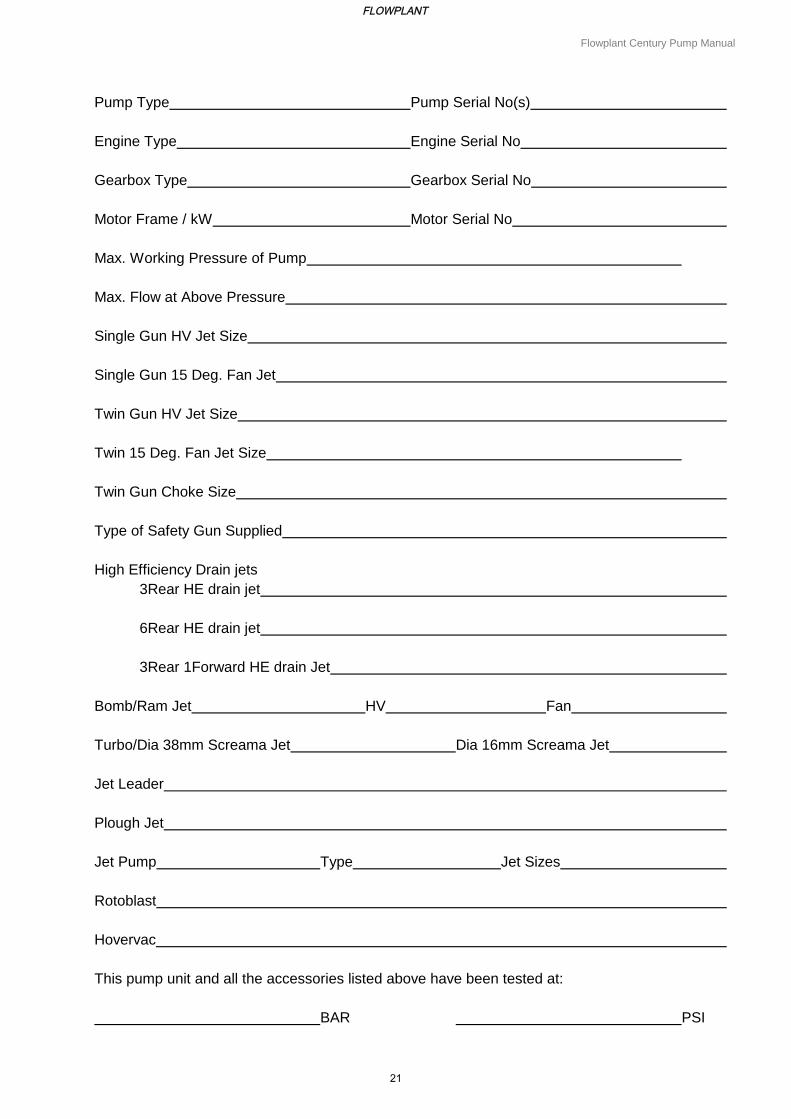
1.5 EQUIPMENT DETAILS
Details relevant to the pump and associated equipment should be entered on the form
shown in Table 1.3, at the rear of this section, for future reference.
1.6 ASSOCIATED PUBLICATIONS
Associated with this manual are the following publications:
Operators guide - Part no. 061-225
Code of practice - Part no. 057-062
FLOWPLANT
17
PARTS LIST
DESCRIPTIONQTYPART NUMBERITEM
1100-3361
BARREL Mk 4 CENTURY81004972
1043-1773
2100-334 Sheet 2
4
8100-0765
1100-6556
NUT DELIVERY TUFTRIDED81002997
1100-6548
9100-1849
Double End Stud8CSN 02 1174 - A M10 x 1610
ISO metric hexagon nuts, including thin
nuts, slotted nuts and castle nuts
4AS 1112 - M10
11
Rotary shaft lip type seals 3 - Assembled1
ANSI/B93.98M - 60x80x8-Type 312
ISO metric hexagon nuts, including thin
nuts, slotted nuts and castle nuts
4AS 1112 - M10 Type 513
ISO metric hexagon nuts, including thin
nuts, slotted nuts and castle nuts
1AS 1112 - M64 Type 514
1100-65215
Hex Head Plug3ASME B16.11 Hex Head Plug 3/816
1100-655_117
1inlet case cutaway - manual drawing18
NUT INLET410049919
1100-51720
8100-34521
1023-30522
1023-72023
1023-59924
1) OIL FILLER
2) WATER INLET
3) WATER DRAIN
4) OIL DRAIN
5) FLENDER PART 4 B200
COUPLING (CLAMPS COUNTER BALANCE)
6) OIL BLEED SCREW B.A.
7) WATER BLEED SCREWS B.A.
FITTED TO TOP BARRELS ONLY
8) HIGH PRESSURE OUTLET G1/2"
9) VIEW EXCLUDING COUPLING AND COUNTER BALANCE
10) 6 STUDS M10x1.5 28mm LG
PUMP DIMENSIONS ARE SYMMETRICAL ABOUT CENTRE LINE
DIMENSIONS ARE IDENTICAL FOR ALL PUMPS
ADAPTORS ARE AVAILABLE FOR A RANGE OF ELECTRIC
MOTORS AND DIESEL ENGINES: CONSULT MANUFACTURER
NOTE: FOR CIRCUIT DIAGRAM SEE DRG D3
AFTER JULY 1982 2" BSP WATER INLET IS STANDARD
FOUR 1 1/4" BSP INLETS ON REQUEST
13.939/13.982
45.000
44.961
39.5/39.3
DRIVE SHAFT DIMENSIONS
KEYWAYS TO BS 4235
567.5
DIMENSIONS (IN mm) ARE IDENTICAL FOR ALL PUMP MODELS
i.e. 4 & 8 CYLINDERS
451
560
ROTATION VIEW ON DRIVE END OF SHAFT
(NOTE CAST ARROW ON INLET SIDE OF PUMP)
MAX. OIL LEVEL 4M FROM
CENTRE LINE OF PUMP
EXPANSION CHAMBER
(CRANKCASE OIL)
21
7
5
8
10
9
6
170 PCD
Fig 1.1 Harben Century Type High Pressure Pump
FLOWPLANT
18
0
2000
4000
6000
8000
10000
12000
0
100
200
300
400
500
600
700
800
0 20 40 60 80 100 120 140 160 180
Pre
ssu
re (
BA
R)
Flow (Litres/min)
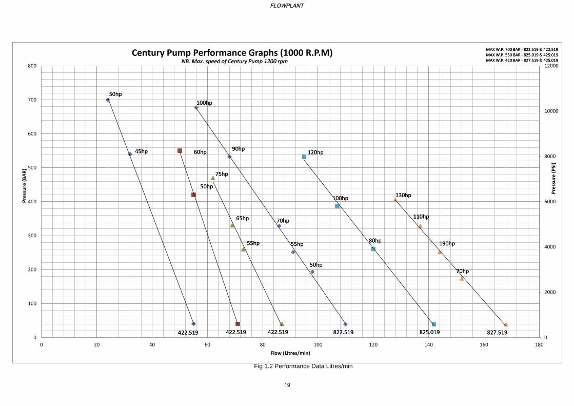
Century Pump Performance Graphs (1000 R.P.M)
50hp
60hp
100hp
120hp
75hp
130hp
MAX W.P. 700 BAR - 822.519 & 422.519 MAX W.P. 550 BAR - 825.019 & 425.019 MAX W.P. 420 BAR - 827.519 & 425.019
NB. Max. speed of Century Pump 1200 rpm
422.519 422.519 422.519 822.519 825.019 827.519
45hp
50hp
65hp
55hp
90hp
70hp
55hp
50hp
100hp
80hp
110hp
190hp
70hp
50hp
60hp
100hp
120hp
75hp
130hp
MAX W.P. 700 BAR - 822.519 & 422.519 MAX W.P. 550 BAR - 825.019 & 425.019 MAX W.P. 420 BAR - 827.519 & 425.019
NB. Max. speed of Century Pump 1200 rpm
422.519 422.519 422.519 822.519 825.019 827.519
45hp
50hp
65hp
55hp
90hp
70hp
55hp
50hp
100hp
80hp
110hp
190hp
70hp
Pre
ssu
re (
PSI
)
Fig 1.2 Performance Data Litres/min
FLOWPLANT
19
george
Text Box
425.019
george
Text Box
427.519
george
Text Box
427.519
0
2000
4000
6000
8000
10000
12000
0
100
200
300
400
500
600
700
800
0 5 10 15 20 25 30 35 40
Pre
ssu
re (
BA
R)
Flow (UK Gal/Min)
Century Pump Performance Graphs (1000 R.P.M)
50hp
60hp
100hp
120hp
75hp
130hp
MAX W.P. 700 BAR - 822.519 & 422.519 MAX W.P. 550 BAR - 825.019 & 425.019 MAX W.P. 420 BAR - 827.519 & 425.019
NB. Max. speed of Century Pump 1200 rpm
422.519 422.519 422.519 822.519 825.019 827.519
45hp
50hp
65hp
55hp
90hp
70hp
55hp
50hp
100hp
80hp
110hp
190hp
70hp
Fig. 1.3 Performance Data UK Gal/min
FLOWPLANT
20
george
Text Box
425.019
george
Text Box
427.519
george
Text Box
427.519
Flowplant Century Pump Manual
Pump Type Pump Serial No(s)
Engine Type Engine Serial No
Gearbox Type Gearbox Serial No
Motor Frame / kW Motor Serial No
Max. Working Pressure of Pump
Max. Flow at Above Pressure
Single Gun HV Jet Size
Single Gun 15 Deg. Fan Jet
Twin Gun HV Jet Size
Twin 15 Deg. Fan Jet Size
Twin Gun Choke Size
Type of Safety Gun Supplied
High Efficiency Drain jets
3Rear HE drain jet
6Rear HE drain jet
3Rear 1Forward HE drain Jet
Bomb/Ram Jet HV Fan
Turbo/Dia 38mm Screama Jet Dia 16mm Screama Jet
Jet Leader
Plough Jet
Jet Pump Type Jet Sizes
Rotoblast
Hovervac
This pump unit and all the accessories listed above have been tested at:
BAR PSI
FLOWPLANT
21
Section 2
Pump Installation
FLOWPLANT
22
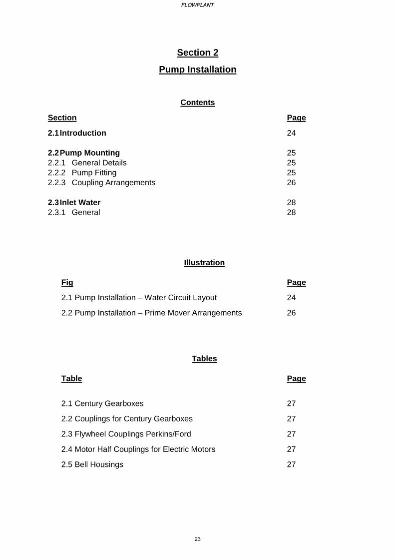
Section 2
Pump Installation
Contents
Section Page
2.1 Introduction 24
2.2 Pump Mounting 25
2.2.1 General Details 25
2.2.2 Pump Fitting 25
2.2.3 Coupling Arrangements 26
2.3 Inlet Water 28
2.3.1 General 28
Illustration
Fig Page
2.1 Pump Installation – Water Circuit Layout 24
2.2 Pump Installation – Prime Mover Arrangements 26
Tables
Table Page
2.1 Century Gearboxes 27
2.2 Couplings for Century Gearboxes 27
2.3 Flywheel Couplings Perkins/Ford 27
2.4 Motor Half Couplings for Electric Motors 27
2.5 Bell Housings 27
FLOWPLANT
23
Flowplant Century Pump Manual
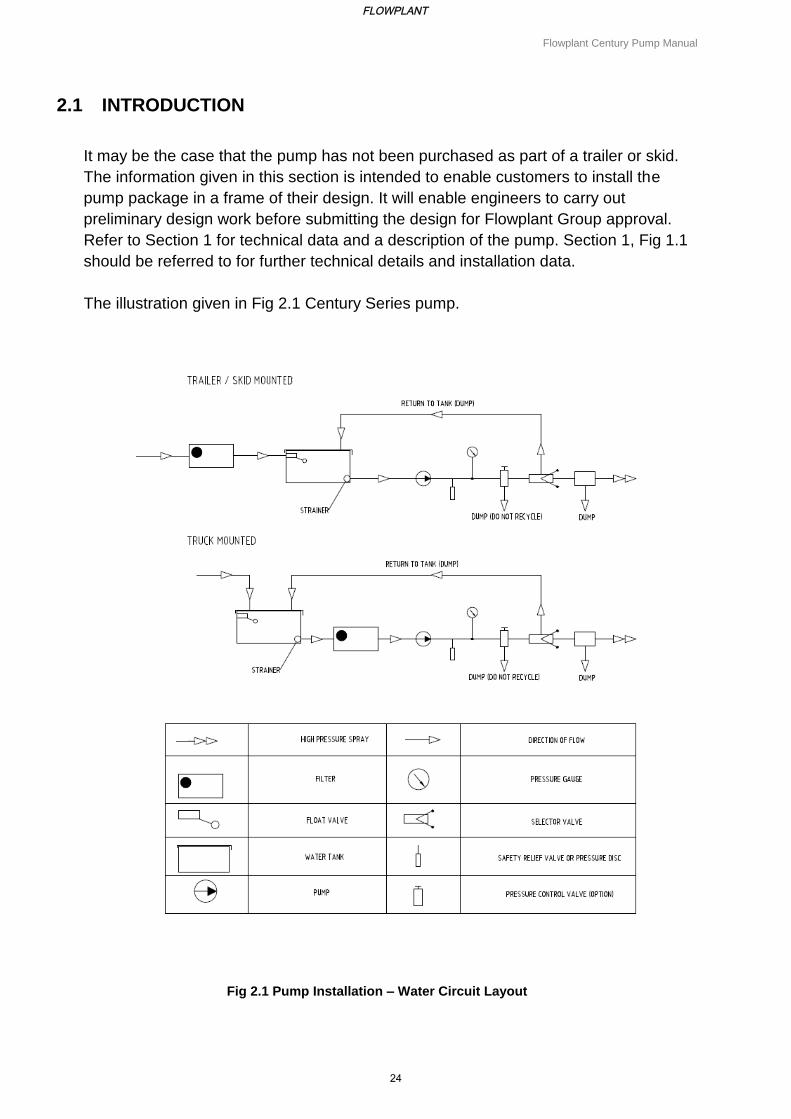
2.1 INTRODUCTION
It may be the case that the pump has not been purchased as part of a trailer or skid.
The information given in this section is intended to enable customers to install the
pump package in a frame of their design. It will enable engineers to carry out
preliminary design work before submitting the design for Flowplant Group approval.
Refer to Section 1 for technical data and a description of the pump. Section 1, Fig 1.1
should be referred to for further technical details and installation data.
The illustration given in Fig 2.1 Century Series pump.
Fig 2.1 Pump Installation – Water Circuit Layout
FLOWPLANT
24
Flowplant Century Pump Manual
2.2 PUMP MOUNTING
2.2.1 General Details
The Century Series pumps are designed for direct drive and flange mounting. The normal operating speed is 1000 rpm, nominal. Maximum operating speed is 1200 rpm. The pump must rotate anticlockwise, looking at the front of the pump ('arrow' cast into crank- case). The maximum inlet water pressure for the pump is 0.5 bar (5.0 metre head), whilst the maximum oil pressure for the pump is 4.0 metre head to centre line of pump. The pump can be inclined between horizontal and 45 degrees (delivery end uppermost). If further inclination is required, between 45 degrees and vertical, Flowplant Group Ltd should be contacted at the address given in Section 1. The weight of a pump with oil in the crankcase, drive coupling fitted and bell housing, depends on the number of cylinders fitted, as follows: 4 cyl - 160 kg 8 cyl - 205 kg The engineer should ensure that all couplings are fitted with a 3 mm clearance. Where a bell housing (pump mounting and coupling shaft and cover) cannot be fitted due to a difference in spigot or bolt locations, an adaptor ring may be fitted. Refer to Para 9 for further details of coupling arrangements. It is recommended that a detailed layout be drawn and the following points considered:
(a) Selection of bell housing most suitable for adaptor ring. Additional machining to the bell housing may be required.
(b) Sufficient coupling engagement on the shaft whilst maintaining the recommended clearance.
(c) Clearance between shafts; careful design can eliminate the shortening of motor/engine shaft.
2.2.2 Pump Fitting
When the pump is to be fitted in position, the following points should be noted:
(a) When the pump is first married up to the prime mover, access is required to check coupling clearance. When Flender B200 couplings are used, sight/gauge holes are drilled in the bell housing for this purpose.
(b) It depends on the particular installation whether the pump head is removed to a workshop for maintenance, e.g. diaphragm or valve replacement or whether work is carried out in-situ.
(c) Where a pump 'strip-down' is required, the pump should be removed to the workshop. The use of an assembly stand (part no 100-279) is recommended.
FLOWPLANT
25
Flowplant Century Pump Manual
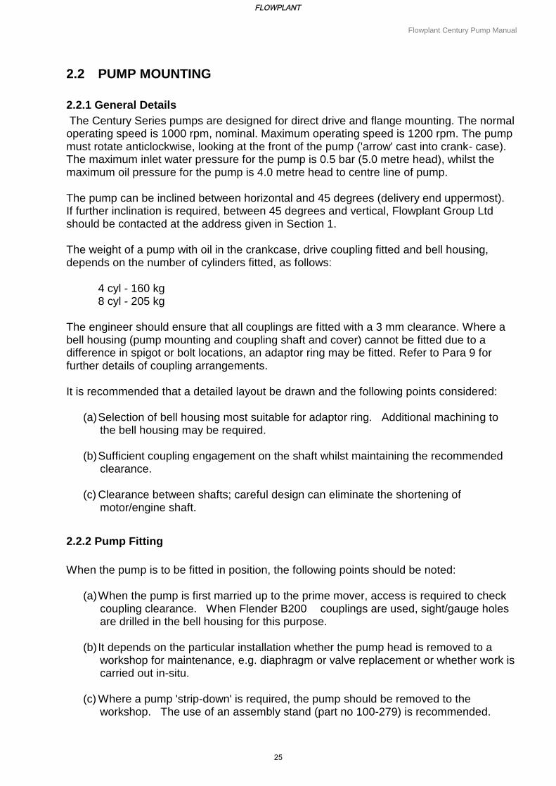
2.2.3 Coupling Arrangements
Arrangements are made on the pump for the incoming fluid to cool the crankcase oil. The use of standard diaphragm/barrel assemblies provides a choice of flows, depending upon the number of barrels fitted to a crankcase. The cylindrical form of these barrels is well suited to containing high pressures. Three piston diameters are available to suit a range of pressure up to 700 bar (10 000 psi).
For details of the prime mover/gearbox/pump coupling arrangements for diesel-driven and
electrically-driven pumps, refer to Fig 2.2 and Tables 2.1 to 2.5.
Fig 2.2 Pump Installation – Prime Movers/Gearbox/Pump Coupling Arrangements
FLOWPLANT
26
Flowplant Century Pump Manual
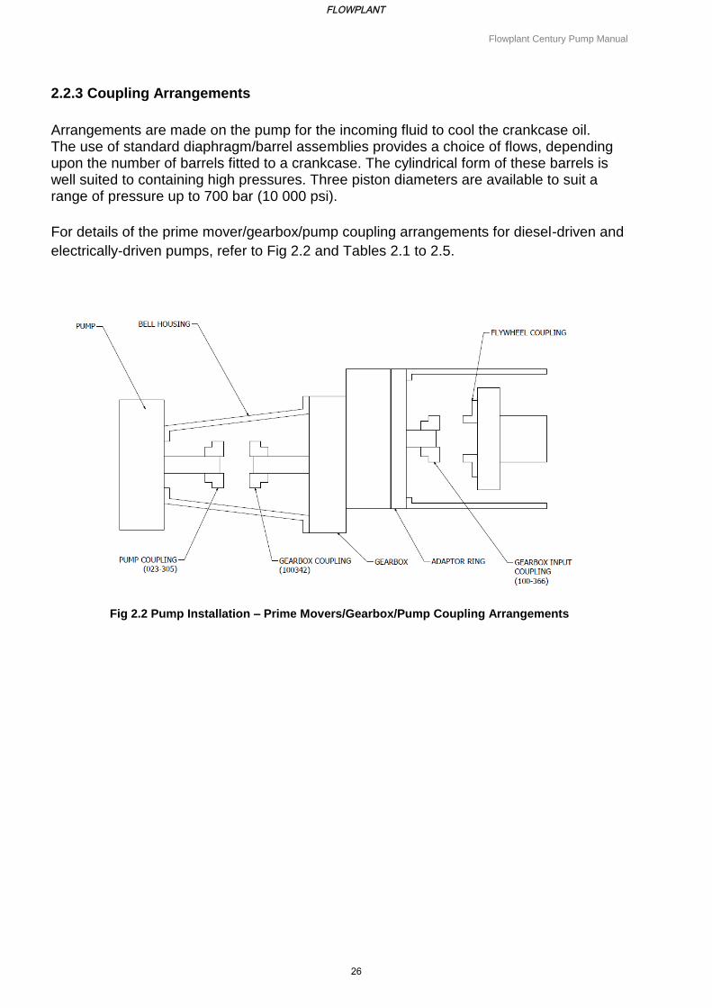
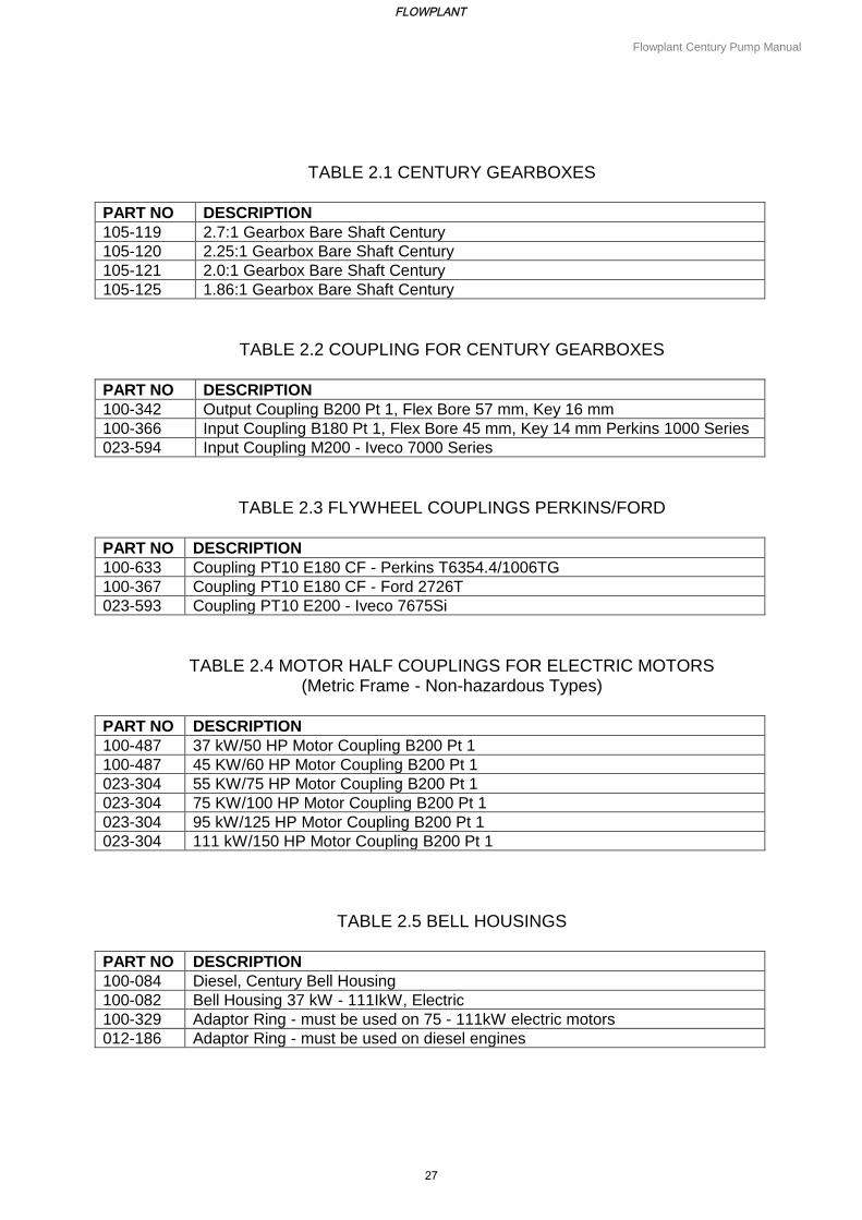
TABLE 2.1 CENTURY GEARBOXES
PART NO DESCRIPTION
105-119 2.7:1 Gearbox Bare Shaft Century
105-120 2.25:1 Gearbox Bare Shaft Century
105-121 2.0:1 Gearbox Bare Shaft Century
105-125 1.86:1 Gearbox Bare Shaft Century
TABLE 2.2 COUPLING FOR CENTURY GEARBOXES
PART NO DESCRIPTION
100-342 Output Coupling B200 Pt 1, Flex Bore 57 mm, Key 16 mm
100-366 Input Coupling B180 Pt 1, Flex Bore 45 mm, Key 14 mm Perkins 1000 Series
023-594 Input Coupling M200 - Iveco 7000 Series
TABLE 2.3 FLYWHEEL COUPLINGS PERKINS/FORD
PART NO DESCRIPTION
100-633 Coupling PT10 E180 CF - Perkins T6354.4/1006TG
100-367 Coupling PT10 E180 CF - Ford 2726T
023-593 Coupling PT10 E200 - Iveco 7675Si
TABLE 2.4 MOTOR HALF COUPLINGS FOR ELECTRIC MOTORS (Metric Frame - Non-hazardous Types)
PART NO DESCRIPTION
100-487 37 kW/50 HP Motor Coupling B200 Pt 1
100-487 45 KW/60 HP Motor Coupling B200 Pt 1
023-304 55 KW/75 HP Motor Coupling B200 Pt 1
023-304 75 KW/100 HP Motor Coupling B200 Pt 1
023-304 95 kW/125 HP Motor Coupling B200 Pt 1
023-304 111 kW/150 HP Motor Coupling B200 Pt 1
TABLE 2.5 BELL HOUSINGS
PART NO DESCRIPTION
100-084 Diesel, Century Bell Housing
100-082 Bell Housing 37 kW - 111IkW, Electric
100-329 Adaptor Ring - must be used on 75 - 111kW electric motors
012-186 Adaptor Ring - must be used on diesel engines
FLOWPLANT
27
Flowplant Century Pump Manual
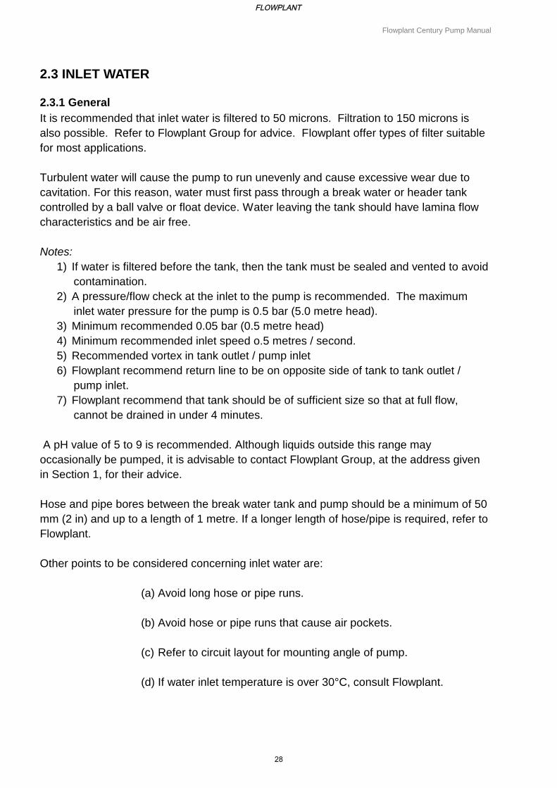
2.3 INLET WATER
2.3.1 General
It is recommended that inlet water is filtered to 50 microns. Filtration to 150 microns is
also possible. Refer to Flowplant Group for advice. Flowplant offer types of filter suitable
for most applications.
Turbulent water will cause the pump to run unevenly and cause excessive wear due to
cavitation. For this reason, water must first pass through a break water or header tank
controlled by a ball valve or float device. Water leaving the tank should have lamina flow
characteristics and be air free.
Notes:
1) If water is filtered before the tank, then the tank must be sealed and vented to avoid
contamination.
2) A pressure/flow check at the inlet to the pump is recommended. The maximum
inlet water pressure for the pump is 0.5 bar (5.0 metre head).
3) Minimum recommended 0.05 bar (0.5 metre head)
4) Minimum recommended inlet speed o.5 metres / second.
5) Recommended vortex in tank outlet / pump inlet
6) Flowplant recommend return line to be on opposite side of tank to tank outlet /
pump inlet.
7) Flowplant recommend that tank should be of sufficient size so that at full flow,
cannot be drained in under 4 minutes.
A pH value of 5 to 9 is recommended. Although liquids outside this range may
occasionally be pumped, it is advisable to contact Flowplant Group, at the address given
in Section 1, for their advice.
Hose and pipe bores between the break water tank and pump should be a minimum of 50
mm (2 in) and up to a length of 1 metre. If a longer length of hose/pipe is required, refer to
Flowplant.
Other points to be considered concerning inlet water are:
(a) Avoid long hose or pipe runs.
(b) Avoid hose or pipe runs that cause air pockets.
(c) Refer to circuit layout for mounting angle of pump.
(d) If water inlet temperature is over 30°C, consult Flowplant.
FLOWPLANT
28

Section 3
General Operating Information
FLOWPLANT
29
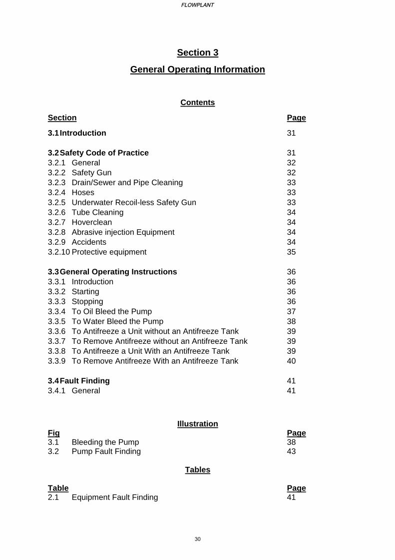
Section 3
General Operating Information
Contents
Section Page
3.1 Introduction 31
3.2 Safety Code of Practice 31
3.2.1 General 32
3.2.2 Safety Gun 32
3.2.3 Drain/Sewer and Pipe Cleaning 33
3.2.4 Hoses 33
3.2.5 Underwater Recoil-less Safety Gun 33
3.2.6 Tube Cleaning 34
3.2.7 Hoverclean 34
3.2.8 Abrasive injection Equipment 34
3.2.9 Accidents 34
3.2.10 Protective equipment 35
3.3 General Operating Instructions 36
3.3.1 Introduction 36
3.3.2 Starting 36
3.3.3 Stopping 36
3.3.4 To Oil Bleed the Pump 37
3.3.5 To Water Bleed the Pump 38
3.3.6 To Antifreeze a Unit without an Antifreeze Tank 39
3.3.7 To Remove Antifreeze without an Antifreeze Tank 39
3.3.8 To Antifreeze a Unit With an Antifreeze Tank 39
3.3.9 To Remove Antifreeze With an Antifreeze Tank 40
3.4 Fault Finding 41
3.4.1 General 41
Illustration Fig Page 3.1 Bleeding the Pump 38 3.2 Pump Fault Finding 43
Tables Table Page 2.1 Equipment Fault Finding 41
FLOWPLANT
30
Flowplant Century Pump Manual
3.1 INTRODUCTION
This section gives general information on safety, protective clothing to be used by operators,
and general starting and stopping procedures when the pump is incorporated in a machine. It
should be remembered that the operating procedures given are to be used as a guide only,
and the equipment handbook operating procedures should be used where applicable.
3.2 SAFETY CODE OF PRACTICE
BASIC RULES
1. ALWAYS WEAR THE CORRECT PROTECTIVE CLOTHING.
2. ALWAYS ENSURE ALL EQUIPMENT IS IN A FIRST CLASS CONDITION.
3. NEVER WORK FROM A LADDER.
4. NEVER USE THE GUN WITH THE TRIGGER LOCKED ON.
NEVER POINT THE GUN AT ANYONE, EVEN IF SWITCHED OFF.
This Code of Practice is intended to provide guidance on the safe operation of high pressure
water jetting equipment.
The term 'high pressure water jetting' covers all water jetting, including the use of additives
and abrasives, where there is an energy input to increase the pressure of water.
This code applies to high pressure water jetting as defined above where there is a
foreseeable risk of injury.
FLOWPLANT
31
Flowplant Century Pump Manual
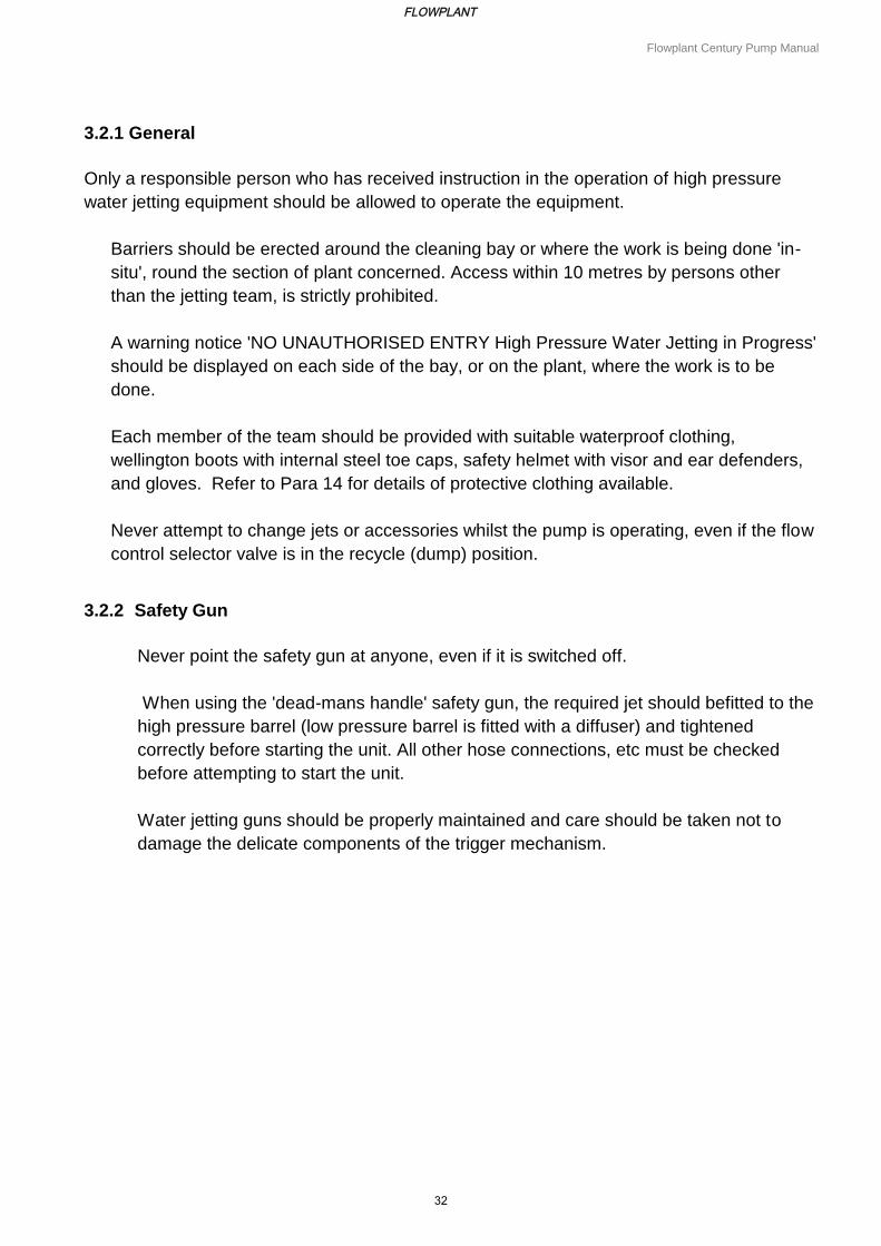
3.2.1 General
Only a responsible person who has received instruction in the operation of high pressure
water jetting equipment should be allowed to operate the equipment.
Barriers should be erected around the cleaning bay or where the work is being done 'in-
situ', round the section of plant concerned. Access within 10 metres by persons other
than the jetting team, is strictly prohibited.
A warning notice 'NO UNAUTHORISED ENTRY High Pressure Water Jetting in Progress'
should be displayed on each side of the bay, or on the plant, where the work is to be
done.
Each member of the team should be provided with suitable waterproof clothing,
wellington boots with internal steel toe caps, safety helmet with visor and ear defenders,
and gloves. Refer to Para 14 for details of protective clothing available.
Never attempt to change jets or accessories whilst the pump is operating, even if the flow
control selector valve is in the recycle (dump) position.
3.2.2 Safety Gun
Never point the safety gun at anyone, even if it is switched off.
When using the 'dead-mans handle' safety gun, the required jet should befitted to the
high pressure barrel (low pressure barrel is fitted with a diffuser) and tightened
correctly before starting the unit. All other hose connections, etc must be checked
before attempting to start the unit.
Water jetting guns should be properly maintained and care should be taken not to
damage the delicate components of the trigger mechanism.
FLOWPLANT
32
Flowplant Century Pump Manual
3.2.3 Drain/Sewer
In addition to the protective clothing listed in Para 5(4), the other equipment should be used
when entering confined spaces, such as safety harness and rescue line, atmospheric
testing equipment, escape breathing apparatus and hand lamps (intrinsically safe
where appropriate).
To prevent snaking or reverse travel of a flexible hose inside the tube being cleaned, a
section of steel pipe, slightly longer than the diameter of the tube to be cleaned, should be
connected between the flexible hose and the nozzle (drain jet extension).
During drain cleaning operations it is advisable to use a coloured leader hose to act as a
warning to the operator that the hose recovery is almost complete.
In addition to Where drain or pipe jetting operations are to be carried out remote from the
high pressure pump unit, i.e. where communication between the person controlling the pump
and the equipment operator is not possible, it is essential that a remote control kit or foot
control valve is used at the work point.
3.2.4 Hoses
Care should be taken to ensure that all hoses are maintained in good condition and are of the correct specification for the pressure being used. Never loop the hose into an excessively tight radius, particularly adjacent to couplings. When fitting re-usable couplings, always ensure that the current type of couplings are being used in relation to the hose specification.
3.2.5 Underwater Recoil-less Safety Gun
The Harben Underwater Recoil-less Safety Gun is designed for use under-water only. Extreme care should be taken to avoid rear-facing balance jets when testing the equipment above water. If working in shallow water, where there is a possibility of the diver surfacing inadvertently during water blasting, care should be taken to ensure that the recoil balance jet protection tube is sufficiently long to prevent the diver directing it at himself.
FLOWPLANT
33
Flowplant Century Pump Manual
3.2.6 Tube Cleaning
Where tube cleaning is to be done by means of a lance, the charge hand who operates the remote control valve should first insert the lance into the tube, leaving the other end of the lance supported by one man. Once the tube has been inserted, the other men required to support the control lance should take up their places, and only then should the charge hand operate the valve.
Note: When the person operating the remote control valve is unable to speak directly to the man, or men, controlling the lance, a clearly understood system of signals and instructions must be agreed upon. A barrier should be placed at the far end of the tube being cleaned for protection against flying debris. A shield fitted to the lance to protect the operator from debris ejected by backward pointing jets should be used for certain operations.
3.2.7 Hoverclean
The angle of the jet holders determine the rotational speed of the spray bar; this is set and locked in position at the works, and on no account must this angle be altered.
3.2.8 Abrasive Injection Equipment
Because water/abrasive jetting can give rise to dangerous splash back, ensure all protective clothing, detailed in 3.2.1, is used. Some abrasives are known to produce residues which may be serious to health and should not be used for blasting, such as sand containing free silica.
3.2.9 Accidents
In the event of a person being injured by the impact of a water jet, the injury caused may appear insignificant and give little indication of the extent of the injury beneath the skin and the damage to deeper tissues. Large quantities of water may have punctured the skin, flesh and organs through a very small hole that may not even bleed/
Operators should carry a card which explains to medical staff the possible nature of the injury, both relating to the high pressure water and any unusual infections that may be found in sewage, such as leptospirosis, better known as Weil's Disease.
FLOWPLANT
34
Flowplant Century Pump Manual
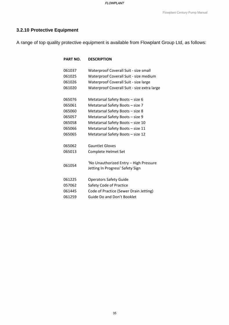
3.2.10 Protective Equipment
A range of top quality protective equipment is available from Flowplant Group Ltd, as follows:
PART NO. DESCRIPTION
061037 Waterproof Coverall Suit - size small
061025 Waterproof Coverall Suit - size medium
061026 Waterproof Coverall Suit - size large
061020 Waterproof Coverall Suit - size extra large
065076 Metatarsal Safety Boots – size 6
065061 Metatarsal Safety Boots – size 7
065060 Metatarsal Safety Boots – size 8
065057 Metatarsal Safety Boots – size 9
065058 Metatarsal Safety Boots – size 10
065066 Metatarsal Safety Boots – size 11
065065 Metatarsal Safety Boots – size 12
065062 Gauntlet Gloves
065013 Complete Helmet Set
061054 ‘No Unauthorized Entry – High Pressure Jetting In Progress’ Safety Sign
061225 Operators Safety Guide
057062 Safety Code of Practice
061445 Code of Practice (Sewer Drain Jetting)
061259 Guide Do and Don’t Booklet
FLOWPLANT
35
Flowplant Century Pump Manual
3.3 GENERAL OPERATING INSTRUCTIONS
3.3.1 Introduction
The following operating instructions are of a general nature with reference being made to the
appropriate manufacturer's handbook for the machine.
3.3.2 Starting
To start the unit, carry out the following instructions:
i. Prior to starting the unit, carry out the following pre-checks:
a) Set the high pressure selector to the recycle (dump) position. b) Ensure the unit is on level ground. c) Check that the water supply is connected and the header tank is full. d) Check that all guns and nozzles are connected. Ensure correct fitting and correct
size for the pressure required.
ii. Start the unit. Refer to the manufacturer's handbook for information concerning engine/electric motor starting procedure. Note: Before starting the unit and carrying out water and/or oil bleed operations (refer to 3.3.4, 3.3.5 respectively), familiarise yourself with the units controls and the stopping instructions (3.3.3).
iii. Move the selector to the High Pressure position.
iv. Increase engine rpm (if diesel) to achieve desired pressure.
3.3.3 Stopping
To shut down the unit, carry out the following instructions:
i. Reduce engine revs to tick-over speed.
ii. Move the high pressure selector to the recycle (dump) position.
iii. Switch off the prime mover by following the instructions given in the manufacturers and book for the engine/electric motor.
iv. If there is the risk of freezing, follow the instructions given the frost precautions
(anti-freeze procedures, (3.3.6, 3.3.8). v. If the unit is to be stored for more than 7 days without running, an inhibitor should be
run through the system. Do not drain prior to storage; always leave full of fresh water or inhibitor.
FLOWPLANT
36
Flowplant Century Pump Manual
vi. Refer to the manufacturer's handbook for information concerning engine/ electric motor protection/storage.
3.3.4 To Oil Bleed the Pump
As delivered from the factory, the pump would have already been oil bled (except pump
heads supplied separately). If necessary, oil bleed the pump as follows:
Note: Refer to the lubrication chart given in Section 4, Table 4.2 for details of pump oil types
and capacities.
i. Fill the pump to the top of the crankcase with the correct oil (or ensure oil is in the expansion bottle, if fitted).
ii. Set the selector valve to the recycle (dump) position and start the engine/motor. Run at 750 rpm tick-over to prime, or inch electric motor (on/off). Note: If the unit is fitted with a shut-down protection device, hold in the override button
for 10 seconds (this allows the engine oil pressure to build up).
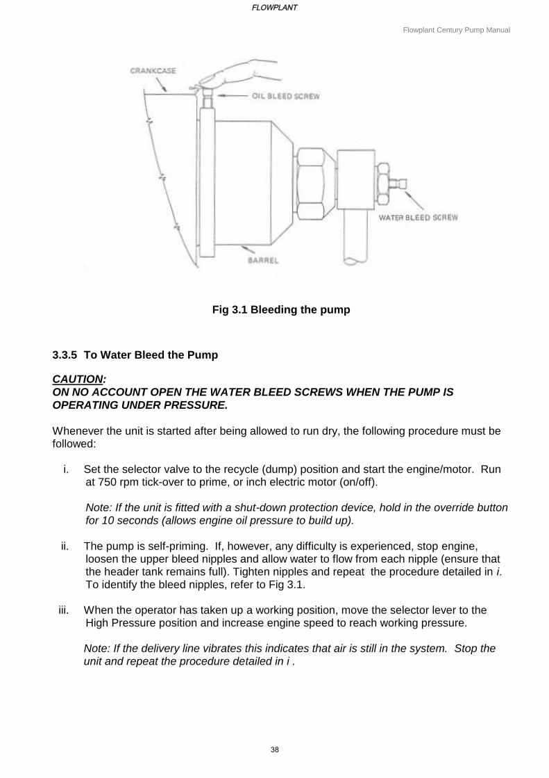
iii. With reference to Fig 3.1, put a finger on top of an oil bleed screw on a lower barrel and open the screw slowly using a suitable spanner. When air-free oil flows, tighten the bleed screw firmly. Note: Top up oil in the pump crankcase after each barrel has been bled.
iv. Repeat the procedure detailed in iii. for each barrel, starting from the lower barrels first.
v. When the operator has taken up a working position, move the selector lever to the
High Pressure position and increase engine speed to reach working pressure.
vi. If the delivery line vibrates or the pump does not run smoothly, stop the unit and carry out a water bleed (3.3.5) and then repeat the oil bleed.
FLOWPLANT
37
Flowplant Century Pump Manual
Fig 3.1 Bleeding the pump
3.3.5 To Water Bleed the Pump
CAUTION: ON NO ACCOUNT OPEN THE WATER BLEED SCREWS WHEN THE PUMP IS OPERATING UNDER PRESSURE.
Whenever the unit is started after being allowed to run dry, the following procedure must be followed:
i. Set the selector valve to the recycle (dump) position and start the engine/motor. Run
at 750 rpm tick-over to prime, or inch electric motor (on/off). Note: If the unit is fitted with a shut-down protection device, hold in the override button for 10 seconds (allows engine oil pressure to build up).
ii. The pump is self-priming. If, however, any difficulty is experienced, stop engine, loosen the upper bleed nipples and allow water to flow from each nipple (ensure that the header tank remains full). Tighten nipples and repeat the procedure detailed in i. To identify the bleed nipples, refer to Fig 3.1.
iii. When the operator has taken up a working position, move the selector lever to the High Pressure position and increase engine speed to reach working pressure. Note: If the delivery line vibrates this indicates that air is still in the system. Stop the unit and repeat the procedure detailed in i .
FLOWPLANT
38
Flowplant Century Pump Manual
3.3.6 To Antifreeze a Unit Without an Antifreeze Tank
i. Prepare 5 gallons (or larger quantity if required) of 30% to 50% anti-freeze solution.
ii. Drain the water tanks.
iii. Pour the anti-freeze solution into the break tanks.
iv. Remove any jet or accessory from the end of the high pressure hose.
v. Ensure the high pressure selector lever is in the dump (or off) position. Start the engine and allow to run for 1 minute.
vi. Holding the outlet end of the hose, move the selector to high pressure position and allow the engine to run until the anti-freeze solution can be seen coming from the high pressure hose.
vii. Stop the engine. The unit is now anti-freezed.
3.3.7 To Remove Antifreeze from a Unit Without an Antifreeze Tank
Note: During this procedure, carry out the air bleed procedure detailed in Para 19, if necessary.
i. Drain any anti-freeze solution from break tanks into a container.
ii. Fill break tanks with water.
iii. Place the outlet of the high pressure hose into the container.
iv. Place the selector lever in the high pressure position, and whilst holding the high pressure hose, start the engine.
v. Run the engine until all solution is returned to the container and clean water is seen flowing from the hose. The unit is now ready to use.
3.3.8 To Antifreeze a Unit with an Antifreeze Tank Fitted
i. Ensure the anti-freeze tank is full of 30% to 50% anti-freeze solution.
ii. Turn the 3-port valve to the anti-freeze position and open valve on the anti-freeze tank (if fitted).
iii. Remove any jet or accessory from the end of the high pressure hose.
FLOWPLANT
39
Flowplant Century Pump Manual
iv. Move the selector lever to the high pressure (or on) position.
v. Holding the end of the hose, start the engine.
vi. Allow engine to run on tick-over until the anti-freeze solution can be seen coming from the high pressure hose.
vii. Move the selector to the recycle (dump) position for 5 seconds (this allows the dump hose to be anti-freezed).
viii. If Jump Jet or Remote Control kits are fitted, ensure they are anti-freezed. The unit is now anti-freezed.
3.3.9 To Remove Antifreeze from a Unit with an Antifreeze Tank Fitted
i. Move the 3-port valve to the water position.
ii. Fill the water tanks.
iii. Place the outlet of the high pressure hose into the anti-freeze tank.
iv. Place the selector lever in the high pressure position.
v. Start the engine. Allow it to run at tick-over and pump anti-freeze solution into the anti freeze tank. Stop the engine when clear water is seen flowing out of the high pressure hose. The unit is now ready to use.
FLOWPLANT
40
Flowplant Century Pump Manual
3.4 FAULT FINDING
3.4.1 General
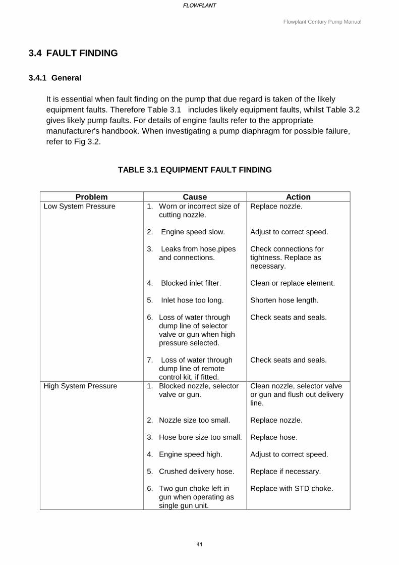
It is essential when fault finding on the pump that due regard is taken of the likely
equipment faults. Therefore Table 3.1 includes likely equipment faults, whilst Table 3.2
gives likely pump faults. For details of engine faults refer to the appropriate
manufacturer's handbook. When investigating a pump diaphragm for possible failure,
refer to Fig 3.2.
TABLE 3.1 EQUIPMENT FAULT FINDING
Problem Cause Action Low System Pressure 1. Worn or incorrect size of
cutting nozzle.
2. Engine speed slow.
3. Leaks from hose,pipes and connections.
4. Blocked inlet filter.
5. Inlet hose too long.
6. Loss of water through dump line of selector valve or gun when high pressure selected.
7. Loss of water through dump line of remote control kit, if fitted.
Replace nozzle. Adjust to correct speed. Check connections for tightness. Replace as necessary. Clean or replace element. Shorten hose length. Check seats and seals. Check seats and seals.
High System Pressure 1. Blocked nozzle, selector valve or gun.
2. Nozzle size too small.
3. Hose bore size too small.
4. Engine speed high.
5. Crushed delivery hose.
6. Two gun choke left in gun when operating as single gun unit.
Clean nozzle, selector valve or gun and flush out delivery line. Replace nozzle. Replace hose. Adjust to correct speed. Replace if necessary. Replace with STD choke.
FLOWPLANT
41
Flowplant Century Pump Manual
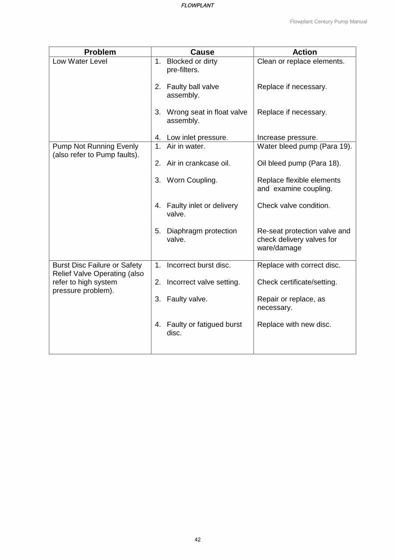
Problem Cause Action Low Water Level 1. Blocked or dirty
pre-filters.
2. Faulty ball valve assembly.
3. Wrong seat in float valve assembly.
4. Low inlet pressure.
Clean or replace elements. Replace if necessary. Replace if necessary. Increase pressure.
Pump Not Running Evenly (also refer to Pump faults).
1. Air in water.
2. Air in crankcase oil.
3. Worn Coupling.
4. Faulty inlet or delivery valve.
5. Diaphragm protection valve.
Water bleed pump (Para 19). Oil bleed pump (Para 18). Replace flexible elements and examine coupling. Check valve condition. Re-seat protection valve and check delivery valves for ware/damage
Burst Disc Failure or Safety Relief Valve Operating (also refer to high system pressure problem).
1. Incorrect burst disc.
2. Incorrect valve setting.
3. Faulty valve.
4. Faulty or fatigued burst disc.
Replace with correct disc. Check certificate/setting. Repair or replace, as necessary. Replace with new disc.
FLOWPLANT
42
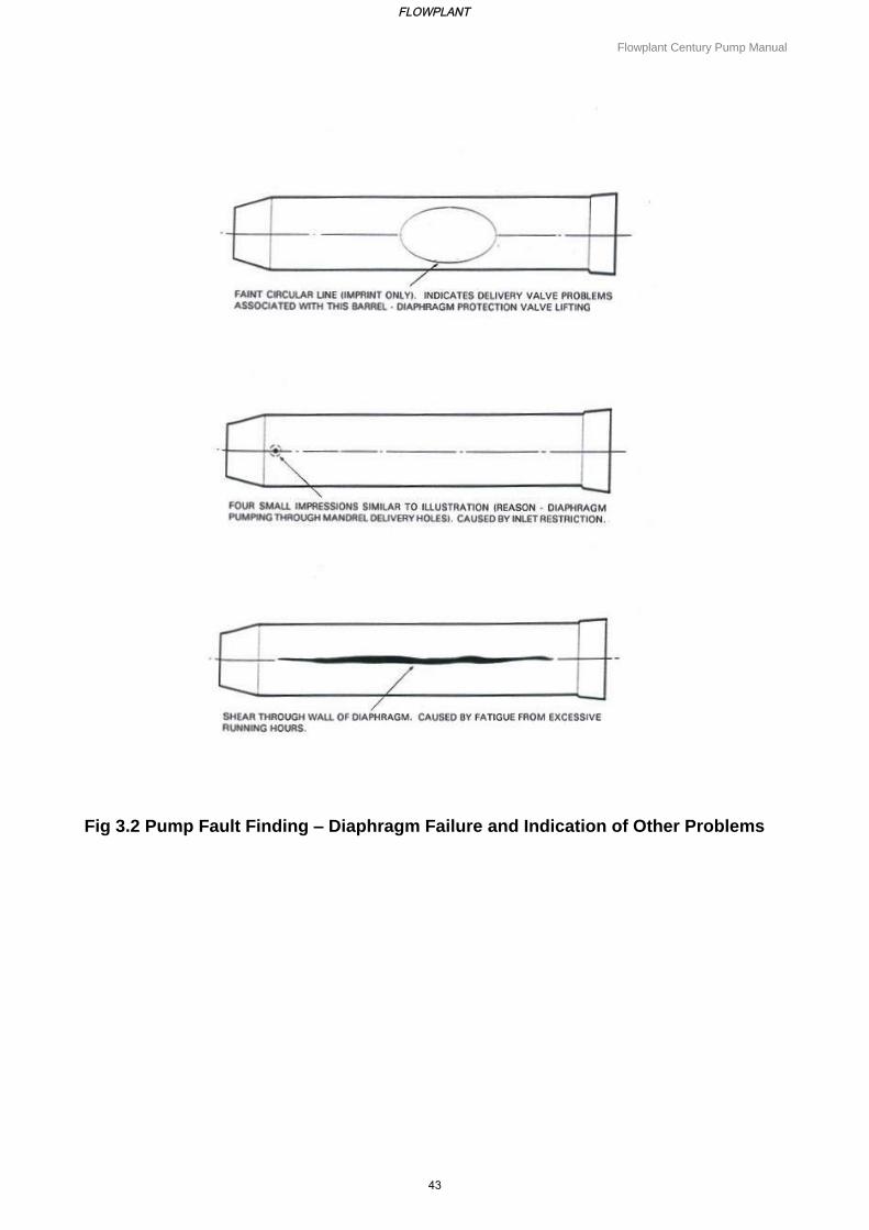
Flowplant Century Pump Manual
Fig 3.2 Pump Fault Finding – Diaphragm Failure and Indication of Other Problems
FLOWPLANT
43
Section 4
Pump Maintenance and
Overhaul Procedures
FLOWPLANT
44
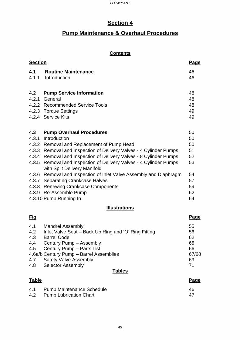
Section 4
Pump Maintenance & Overhaul Procedures
Contents
Section Page
4.1 Routine Maintenance 46
4.1.1 Introduction 46
4.2 Pump Service Information 48
4.2.1 General 48
4.2.2 Recommended Service Tools 48
4.2.3 Torque Settings 49
4.2.4 Service Kits 49
4.3 Pump Overhaul Procedures 50
4.3.1 Introduction 50
4.3.2 Removal and Replacement of Pump Head 50
4.3.3 Removal and Inspection of Delivery Valves - 4 Cylinder Pumps 51
4.3.4 Removal and Inspection of Delivery Valves - 8 Cylinder Pumps 52
4.3.5 Removal and Inspection of Delivery Valves - 4 Cylinder Pumps 53
with Split Delivery Manifold
4.3.6 Removal and Inspection of Inlet Valve Assembly and Diaphragm 54
4.3.7 Separating Crankcase Halves 57
4.3.8 Renewing Crankcase Components 59
4.3.9 Re-Assemble Pump 62
4.3.10 Pump Running In 64
Illustrations
Fig Page
4.1 Mandrel Assembly 55 4.2 Inlet Valve Seat – Back Up Ring and ‘O’ Ring Fitting 56 4.3 Barrel Code 62 4.4 Century Pump – Assembly 65 4.5 Century Pump – Parts List 66 4.6a/b Century Pump – Barrel Assemblies 67/68 4.7 Safety Valve Assembly 69 4.8 Selector Assembly 71
Tables
Table Page
4.1 Pump Maintenance Schedule 46 4.2 Pump Lubrication Chart 47
FLOWPLANT
45
Flowplant Century Pump Manual
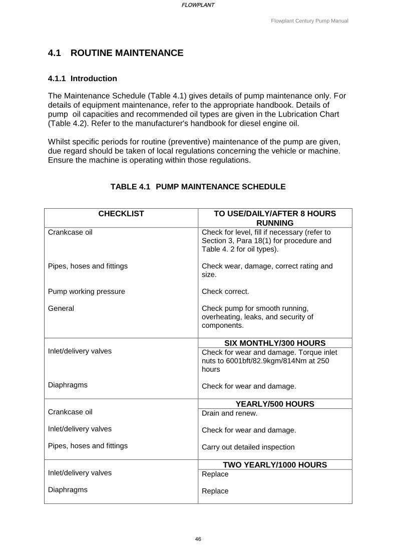
4.1 ROUTINE MAINTENANCE
4.1.1 Introduction
The Maintenance Schedule (Table 4.1) gives details of pump maintenance only. For details of equipment maintenance, refer to the appropriate handbook. Details of pump oil capacities and recommended oil types are given in the Lubrication Chart (Table 4.2). Refer to the manufacturer's handbook for diesel engine oil. Whilst specific periods for routine (preventive) maintenance of the pump are given, due regard should be taken of local regulations concerning the vehicle or machine. Ensure the machine is operating within those regulations.
TABLE 4.1 PUMP MAINTENANCE SCHEDULE
CHECKLIST TO USE/DAILY/AFTER 8 HOURS
RUNNING Crankcase oil Pipes, hoses and fittings Pump working pressure General
Check for level, fill if necessary (refer to Section 3, Para 18(1) for procedure and Table 4. 2 for oil types). Check wear, damage, correct rating and size. Check correct. Check pump for smooth running, overheating, leaks, and security of components.
Inlet/delivery valves Diaphragms
SIX MONTHLY/300 HOURS Check for wear and damage. Torque inlet nuts to 6001bft/82.9kgm/814Nm at 250 hours Check for wear and damage.
Crankcase oil Inlet/delivery valves Pipes, hoses and fittings
YEARLY/500 HOURS Drain and renew. Check for wear and damage. Carry out detailed inspection
Inlet/delivery valves Diaphragms
TWO YEARLY/1000 HOURS Replace Replace
FLOWPLANT
46
Flowplant Century Pump Manual
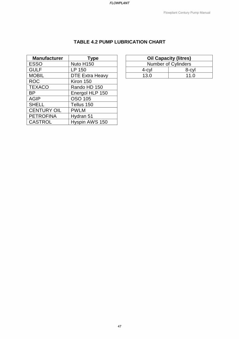
TABLE 4.2 PUMP LUBRICATION CHART
Manufacturer Type Oil Capacity (litres)
ESSO Nuto H150 Number of Cylinders
GULF LP 150 4-cyl 8-cyl
MOBIL DTE Extra Heavy 13.0 11.0
ROC Kiron 150
TEXACO Rando HD 150
BP Energol HLP 150
AGIP OSO 105
SHELL Tellus 150
CENTURY OIL PWLM
PETROFINA Hydran 51
CASTROL Hyspin AWS 150
FLOWPLANT
47
Flowplant Century Pump Manual
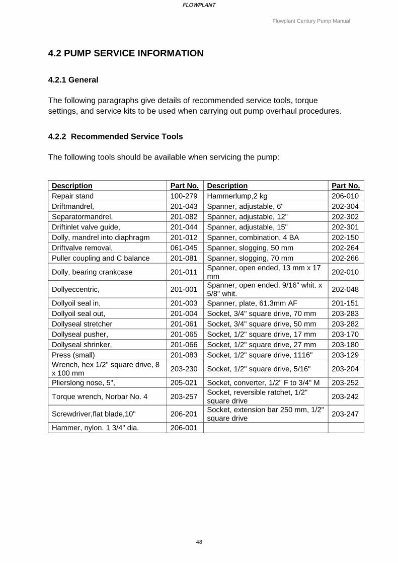
4.2 PUMP SERVICE INFORMATION
4.2.1 General
The following paragraphs give details of recommended service tools, torque
settings, and service kits to be used when carrying out pump overhaul procedures.
4.2.2 Recommended Service Tools
The following tools should be available when servicing the pump:
Description Part No. Description Part No.
Repair stand 100-279 Hammerlump,2 kg 206-010
Driftmandrel, 201-043 Spanner, adjustable, 6" 202-304
Separatormandrel, 201-082 Spanner, adjustable, 12" 202-302
Driftinlet valve guide, 201-044 Spanner, adjustable, 15" 202-301
Dolly, mandrel into diaphragm 201-012 Spanner, combination, 4 BA 202-150
Driftvalve removal, 061-045 Spanner, slogging, 50 mm 202-264
Puller coupling and C balance 201-081 Spanner, slogging, 70 mm 202-266
Dolly, bearing crankcase 201-011 Spanner, open ended, 13 mm x 17 mm
202-010
Dollyeccentric, 201-001 Spanner, open ended, 9/16" whit. x 5/8" whit.
202-048
Dollyoil seal in, 201-003 Spanner, plate, 61.3mm AF 201-151
Dollyoil seal out, 201-004 Socket, 3/4" square drive, 70 mm 203-283
Dollyseal stretcher 201-061 Socket, 3/4" square drive, 50 mm 203-282
Dollyseal pusher, 201-065 Socket, 1/2" square drive, 17 mm 203-170
Dollyseal shrinker, 201-066 Socket, 1/2" square drive, 27 mm 203-180
Press (small) 201-083 Socket, 1/2" square drive, 1116" 203-129
Wrench, hex 1/2" square drive, 8 x 100 mm
203-230 Socket, 1/2" square drive, 5/16" 203-204
Plierslong nose, 5", 205-021 Socket, converter, 1/2" F to 3/4" M 203-252
Torque wrench, Norbar No. 4 203-257 Socket, reversible ratchet, 1/2" square drive
203-242
Screwdriver,flat blade,10" 206-201 Socket, extension bar 250 mm, 1/2" square drive
203-247
Hammer, nylon. 1 3/4" dia. 206-001
FLOWPLANT
48
Flowplant Century Pump Manual
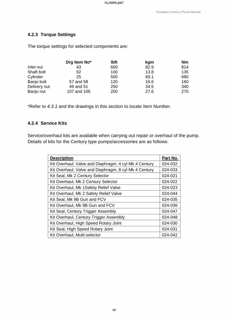
4.2.3 Torque Settings
The torque settings for selected components are:
Drg Item No* lbft kgm Nm Inlet nut 43 600 82.9 814 Shaft bolt 92 100 13.8 135 Cylinder 25 500 69.1 680 Banjo bolt 57 and 58 120 16.6 160 Delivery nut 49 and 51 250 34.5 340 Banjo nut 107 and 106 200 27.6 270
*Refer to 4.3.1 and the drawings in this section to locate Item Number.
4.2.4 Service Kits
Service/overhaul kits are available when carrying out repair or overhaul of the pump.
Details of kits for the Century type pumps/accessories are as follows:
Description Part No.
Kit Overhaul, Valve and Diaphragm, 4 cyl Mk 4 Century 024-032
Kit Overhaul, Valve and Diaphragm, 8 cyl Mk 4 Century 024-033
Kit Seal, Mk 2 Century Selector 024-021
Kit Overhaul, Mk 2 Century Selector 024-022
Kit Overhaul, Mk 1Safety Relief Valve 024-023
Kit Overhaul, Mk 2 Safety Relief Valve 024-044
Kit Seal, Mk 9B Gun and FCV 024-035
Kit Overhaul, Mk 9B Gun and FCV 024-036
Kit Seal, Century Trigger Assembly 024-047
Kit Overhaul, Century Trigger Assembly 024-048
Kit Overhaul, High Speed Rotary Joint 024-030
Kit Seal, High Speed Rotary Joint 024-031
Kit Overhaul, Multi-selector 024-042
FLOWPLANT
49
Flowplant Century Pump Manual
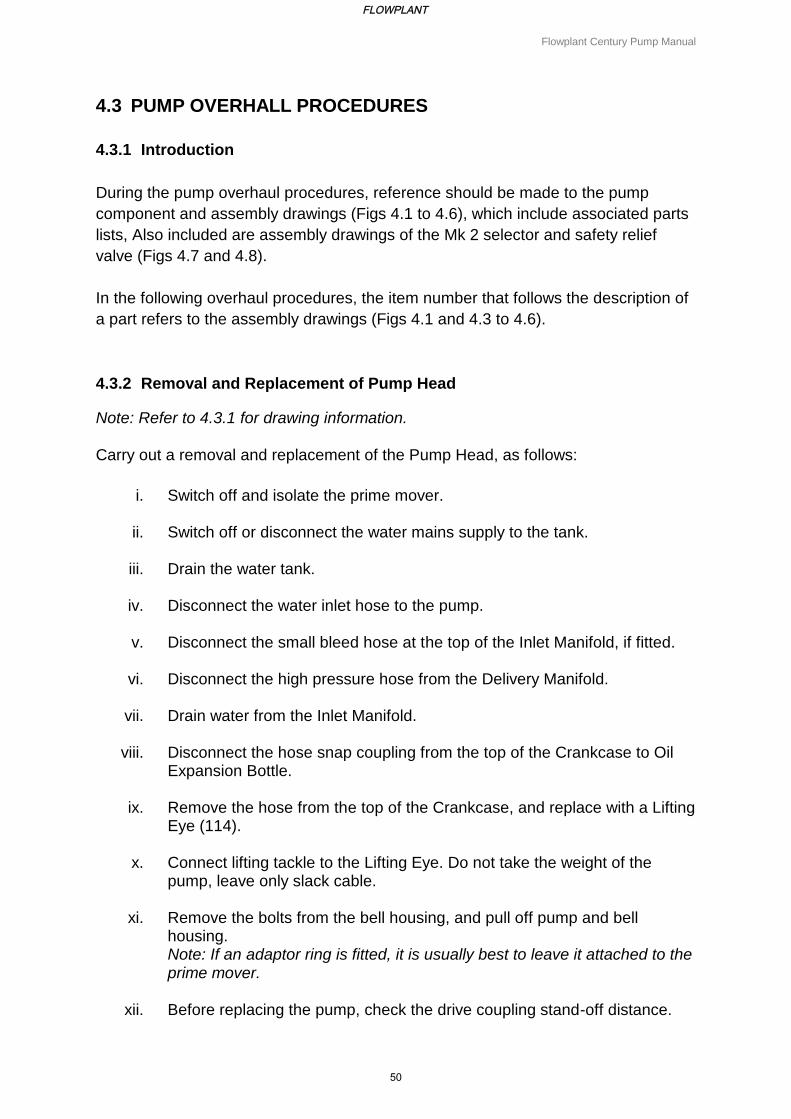
4.3 PUMP OVERHALL PROCEDURES
4.3.1 Introduction
During the pump overhaul procedures, reference should be made to the pump
component and assembly drawings (Figs 4.1 to 4.6), which include associated parts
lists, Also included are assembly drawings of the Mk 2 selector and safety relief
valve (Figs 4.7 and 4.8).
In the following overhaul procedures, the item number that follows the description of
a part refers to the assembly drawings (Figs 4.1 and 4.3 to 4.6).
4.3.2 Removal and Replacement of Pump Head
Note: Refer to 4.3.1 for drawing information.
Carry out a removal and replacement of the Pump Head, as follows:
i. Switch off and isolate the prime mover.
ii. Switch off or disconnect the water mains supply to the tank.
iii. Drain the water tank.
iv. Disconnect the water inlet hose to the pump.
v. Disconnect the small bleed hose at the top of the Inlet Manifold, if fitted.
vi. Disconnect the high pressure hose from the Delivery Manifold.
vii. Drain water from the Inlet Manifold.
viii. Disconnect the hose snap coupling from the top of the Crankcase to Oil Expansion Bottle.
ix. Remove the hose from the top of the Crankcase, and replace with a Lifting Eye (114).
x. Connect lifting tackle to the Lifting Eye. Do not take the weight of the pump, leave only slack cable.
xi. Remove the bolts from the bell housing, and pull off pump and bell housing. Note: If an adaptor ring is fitted, it is usually best to leave it attached to the prime mover.
xii. Before replacing the pump, check the drive coupling stand-off distance.
FLOWPLANT
50
Flowplant Century Pump Manual
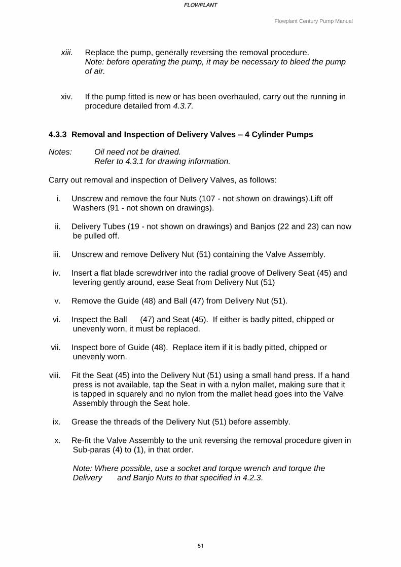
xiii. Replace the pump, generally reversing the removal procedure. Note: before operating the pump, it may be necessary to bleed the pump of air.
xiv. If the pump fitted is new or has been overhauled, carry out the running in procedure detailed from 4.3.7.
4.3.3 Removal and Inspection of Delivery Valves – 4 Cylinder Pumps
Notes: Oil need not be drained. Refer to 4.3.1 for drawing information.
Carry out removal and inspection of Delivery Valves, as follows:
i. Unscrew and remove the four Nuts (107 - not shown on drawings).Lift off Washers (91 - not shown on drawings).
ii. Delivery Tubes (19 - not shown on drawings) and Banjos (22 and 23) can now be pulled off.
iii. Unscrew and remove Delivery Nut (51) containing the Valve Assembly. iv. Insert a flat blade screwdriver into the radial groove of Delivery Seat (45) and
levering gently around, ease Seat from Delivery Nut (51)
v. Remove the Guide (48) and Ball (47) from Delivery Nut (51). vi. Inspect the Ball (47) and Seat (45). If either is badly pitted, chipped or
unevenly worn, it must be replaced. vii. Inspect bore of Guide (48). Replace item if it is badly pitted, chipped or
unevenly worn. viii. Fit the Seat (45) into the Delivery Nut (51) using a small hand press. If a hand
press is not available, tap the Seat in with a nylon mallet, making sure that it is tapped in squarely and no nylon from the mallet head goes into the Valve Assembly through the Seat hole.
ix. Grease the threads of the Delivery Nut (51) before assembly.
x. Re-fit the Valve Assembly to the unit reversing the removal procedure given in
Sub-paras (4) to (1), in that order. Note: Where possible, use a socket and torque wrench and torque the Delivery and Banjo Nuts to that specified in 4.2.3.
FLOWPLANT
51
Flowplant Century Pump Manual
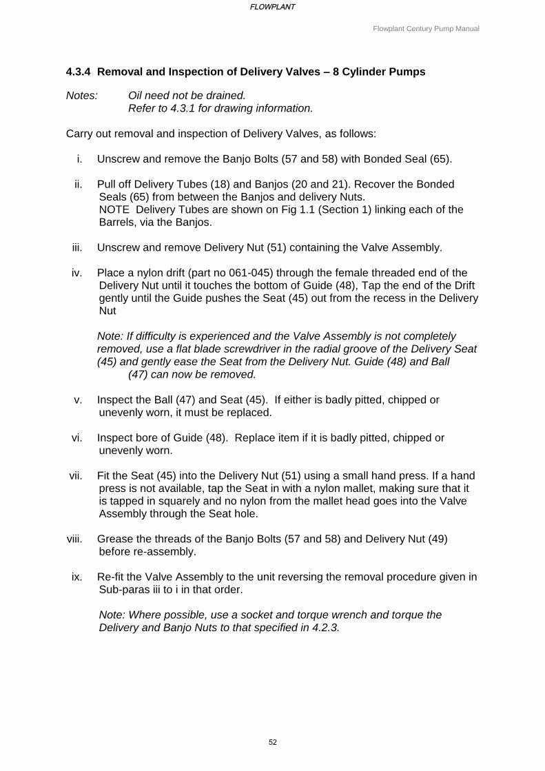
4.3.4 Removal and Inspection of Delivery Valves – 8 Cylinder Pumps
Notes: Oil need not be drained. Refer to 4.3.1 for drawing information.
Carry out removal and inspection of Delivery Valves, as follows:
i. Unscrew and remove the Banjo Bolts (57 and 58) with Bonded Seal (65).
ii. Pull off Delivery Tubes (18) and Banjos (20 and 21). Recover the Bonded Seals (65) from between the Banjos and delivery Nuts. NOTE Delivery Tubes are shown on Fig 1.1 (Section 1) linking each of the Barrels, via the Banjos.
iii. Unscrew and remove Delivery Nut (51) containing the Valve Assembly. iv. Place a nylon drift (part no 061-045) through the female threaded end of the
Delivery Nut until it touches the bottom of Guide (48), Tap the end of the Drift gently until the Guide pushes the Seat (45) out from the recess in the Delivery Nut Note: If difficulty is experienced and the Valve Assembly is not completely removed, use a flat blade screwdriver in the radial groove of the Delivery Seat (45) and gently ease the Seat from the Delivery Nut. Guide (48) and Ball (47) can now be removed.
v. Inspect the Ball (47) and Seat (45). If either is badly pitted, chipped or
unevenly worn, it must be replaced. vi. Inspect bore of Guide (48). Replace item if it is badly pitted, chipped or
unevenly worn. vii. Fit the Seat (45) into the Delivery Nut (51) using a small hand press. If a hand
press is not available, tap the Seat in with a nylon mallet, making sure that it is tapped in squarely and no nylon from the mallet head goes into the Valve Assembly through the Seat hole.
viii. Grease the threads of the Banjo Bolts (57 and 58) and Delivery Nut (49)
before re-assembly. ix. Re-fit the Valve Assembly to the unit reversing the removal procedure given in
Sub-paras iii to i in that order. Note: Where possible, use a socket and torque wrench and torque the Delivery and Banjo Nuts to that specified in 4.2.3.
FLOWPLANT
52
Flowplant Century Pump Manual
4.3.5 Removal and Inspection of Delivery Valves – 8 Cylinder Pumps with Split
Delivery Manifold
Notes: Oil need not be drained. Refer to 4.3.1 for drawing information.
Carry out removal and inspection of Delivery Valves, as follows:
i. Unscrew and remove the four Nuts (106 - not shown on drawings).
ii. Lift off Washers (90 - not shown on drawings)
iii. Delivery Tubes (19 - not shown on drawings) and Banjos (22 and 23) can
now be pulled off.
iv. Unscrew and remove the four Nuts (107 - not shown on drawings).
v. Lift off Washers (91- not shown on drawings).
vi. The second set of Delivery Tubes and Banjos can now be pulled off.
vii. Unscrew and remove Delivery Nuts (50 and 51) containing the Valve Assembly.
viii. Insert a flat blade screwdriver into the radial groove of Delivery Seat (45) and levering gently around, ease Seat from Delivery Nut (50 and 51)
ix. Remove the Guide (48) and Ball (47) from Delivery Nut (50 and 51).
x. Inspect the Ball (47) and Seat (45). If either is badly pitted, chipped or unevenly worn, it must be replaced.
xi. Inspect bore of Guide (48). Replace item if it is badly pitted, chipped or unevenly worn.
xii. Fit the Seat (45) into the Delivery Nut (50 and 51) using a small hand press. If a hand press is not available, tap the Seat in with a nylon mallet, making sure that it is tapped in squarely and no nylon from the mallet head goes into the Valve Assembly through the Seat hole.
xiii. Grease the threads of the Delivery Nuts (50 and 51) before assembly. xiv. Re-fit the Valve Assembly to the unit reversing the removal procedure
given in Sub-paras (7) to (1), in that order.
Note: Where possible, use a socket and torque wrench and torque the Delivery and Banjo Nuts to that specified in 4.2.3.
FLOWPLANT
53
Flowplant Century Pump Manual
4.3.6 Removal and Inspection of Inlet Valve Assembly and Diaphragm
Notes: It is reccomended that oil is drained from the pump before commencing the following procedure. Refer to 4.3.1 for drawing information.
The initial dismantling procedure depends upon the type of pump, as follows:
i. If 4-cylinder pump, carry out the procedure detailed in 4.3.3, i to iv.
ii. If 8-cylinder pump, carry out the procedure detailed in 4.3.4, i to iii.
iii. If 8-cylinder pump with split delivery manifold, carry out the procedure detailed in 4.3.5, i to vii.
With the appropriate initial dismantling procedure completed, carry out removal and
inspection of the Inlet Valve Assembly and Diaphragm, as follows:
i. Unscrew and remove Nuts (105).
ii. Pull the Inlet Manifold (16) off its Studs (101).
iii. Unscrew Inlet Nuts (43) using a 70 mm slogging spanner (part no 202-266), taking care not to damage Studs (101).
iv. Insert a Drift (part no 201-043) into the end of the Mandrel, from delivery end. Tap the end of the Drift to remove Collar (42), Inlet Seat (41), Spring (36), Valve 40, Mandrel Assembly (38) and Diaphragm (37) from the inlet end of the Barrel.
v. Pull the Inlet Seat (41) from the Mandrel Assembly (38). Remove Valve (40) and Spring (36).
vi. Using Extractor (part no 201-082), remove Diaphragm (37) from Mandrel Assembly (38). Inspect the Diaphragm for splits or holes, replace if necessary.
vii. Inspect Spring (36), replace if necessary.
viii. Inspect the seating faces of the Valve (40) and Seat (41). If either is badly pitted, chipped or unevenly worn, it must be replaced.
ix. Inspect the bore of Bush (114).. It should be noted that if the bore is worn it will prevent Valve (40) from shutting smoothly and squarely onto the Seat(41) and must be replaced if necessary. The procedure for replacing the Bush is as follows:
a. Remove the Pin (115).
b. Screw an M12 tap into the Bush (114) until it bottoms.
FLOWPLANT
54
Flowplant Century Pump Manual
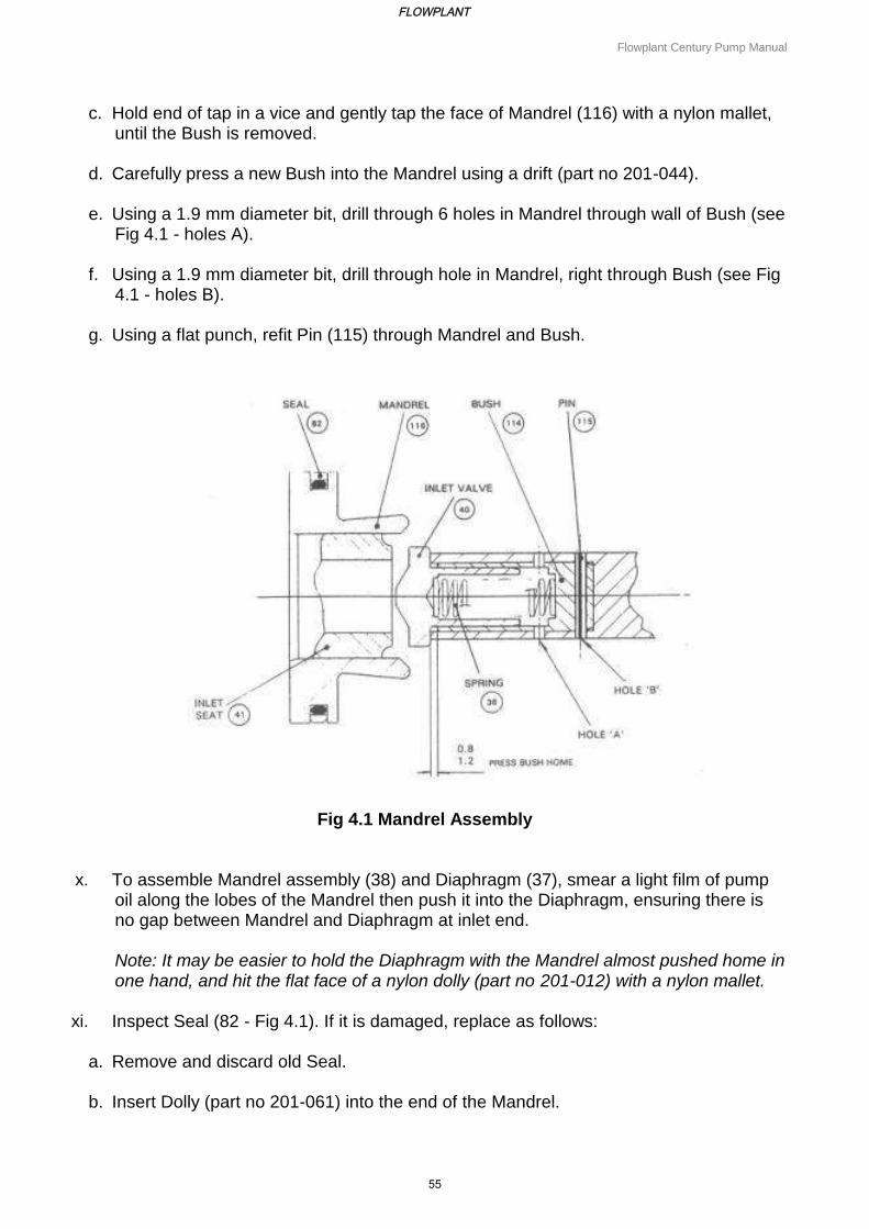
c. Hold end of tap in a vice and gently tap the face of Mandrel (116) with a nylon mallet, until the Bush is removed.
d. Carefully press a new Bush into the Mandrel using a drift (part no 201-044).
e. Using a 1.9 mm diameter bit, drill through 6 holes in Mandrel through wall of Bush (see Fig 4.1 - holes A).
f. Using a 1.9 mm diameter bit, drill through hole in Mandrel, right through Bush (see Fig
4.1 - holes B).
g. Using a flat punch, refit Pin (115) through Mandrel and Bush.
Fig 4.1 Mandrel Assembly
x. To assemble Mandrel assembly (38) and Diaphragm (37), smear a light film of pump oil along the lobes of the Mandrel then push it into the Diaphragm, ensuring there is no gap between Mandrel and Diaphragm at inlet end. Note: It may be easier to hold the Diaphragm with the Mandrel almost pushed home in one hand, and hit the flat face of a nylon dolly (part no 201-012) with a nylon mallet.
xi. Inspect Seal (82 - Fig 4.1). If it is damaged, replace as follows:
a. Remove and discard old Seal.
b. Insert Dolly (part no 201-061) into the end of the Mandrel.
FLOWPLANT
55
Flowplant Century Pump Manual
c. Fit '0' ring part of Seal into the groove of the Mandrel.
d. Push the hard plastic part of Seal over the Dolly, using Pusher (part no 201-065), and locate it in the groove on top of the '0' ring part of the Seal.
e. Using Shrinker (part no 201-066), shrink the Seal enough to fit into the Barrel without damage.
xii. Place Valve (40) and Spring (36) into Bush (114).
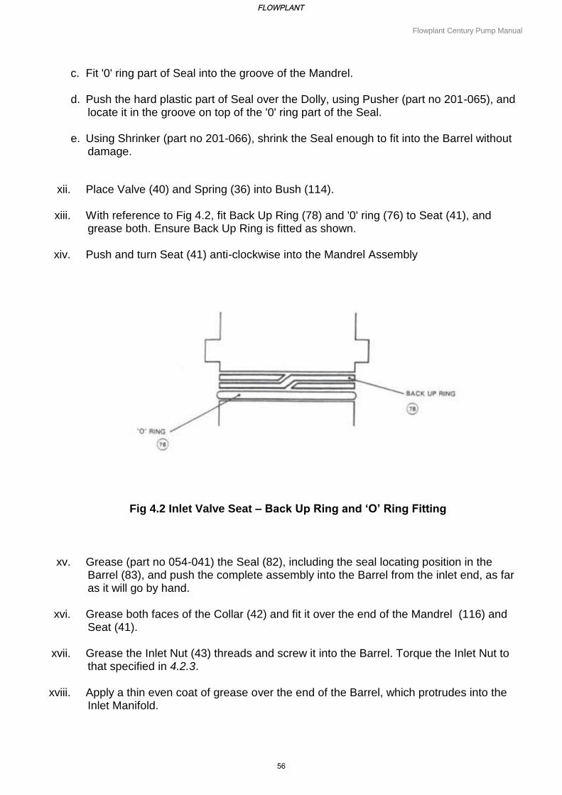
xiii. With reference to Fig 4.2, fit Back Up Ring (78) and '0' ring (76) to Seat (41), and grease both. Ensure Back Up Ring is fitted as shown.
xiv. Push and turn Seat (41) anti-clockwise into the Mandrel Assembly
Fig 4.2 Inlet Valve Seat – Back Up Ring and ‘O’ Ring Fitting
xv. Grease (part no 054-041) the Seal (82), including the seal locating position in the Barrel (83), and push the complete assembly into the Barrel from the inlet end, as far as it will go by hand.
xvi. Grease both faces of the Collar (42) and fit it over the end of the Mandrel (116) and Seat (41).
xvii. Grease the Inlet Nut (43) threads and screw it into the Barrel. Torque the Inlet Nut to that specified in 4.2.3.
xviii. Apply a thin even coat of grease over the end of the Barrel, which protrudes into the Inlet Manifold.
FLOWPLANT
56
Flowplant Century Pump Manual
xix. Check '0' rings (68 and 69) are not damaged and are in place.
xx. Locate the Inlet Manifold (16) on to Studs (101) and fit Nuts (105) and Washers (85).
xxi. Fill the pump with oil (see Table 4.2 for oil types), and bleed each individual cylinder using Bleed Screws (93).
xxii. Depending upon the type of pump, carry out a reversal of the initial dismantling procedure detailed in 4.3.6.
xxiii. The pump may now require further oil bleeding in accordance with the procedure detailed in Section 3.3.4.
4.3.7 Separating Crankcase Halves
To inspect/overhaul components within the Crankcase, the two halves of the Crankcase have to be separated. Although this operation can be achieved on the power unit, it is recommended that the pump is removed from the unit and placed in a Century Pump Stand (part no 100-279). Separate the Crankcase halves as follows: Note: Refer to 4.3.1 for drawing information.
i. Remove the pump as detailed in 4.3.2 (removal and replacement of pump head).
ii. Unscrew the Capscrew (102). If necessary hold the Coupling (5) to stop the Shaft (17) rotating.
iii. Lift the Cap (56) out of the recess in the end of the Coupling (5).
iv. Remove Coupling (5) and Counter Balance (4) from the Shaft (17). This operation is made easier using a Puller (part no 201-081).
v. Unscrew and remove Nuts (86) and Washers (103).
vi. Remove the Bell Housing (84).
vii. Remove Key (30) from the Shaft (17).
viii. Place the pump in the repair stand.
ix. Drain the oil from the pump into a suitable container.
x. Depending on the type of pump, carry out one of the following operations:
a. If unit contains a 4-cylinder pump, carry out the procedure detailed in 4.3.3. I to iii.
b. If unit contains an 8-cylinder pump, carry out the procedure detailed in 4.3.4 I to iii.
FLOWPLANT
57

Flowplant Century Pump Manual
c. If unit contains an 8-cylinder pump with split delivery manifold, carry out the procedure detailed in 4.3.5 I to vi.
xi. Unscrew and remove Nuts (105).
xii. Pull Inlet Manifold (16) off of Studs (101).
Note: Depending on the nature of the repair or investigation, either complete the appropriate operation for the pump detailed in 4.3.3, .4 or .5, or continue this procedure from 4.3.7 xiii.
xiii. Unscrew and remove the Bleed Screws (93) and pull the Bleed Ring (44) off the Barrel.
xiv. Unscrew Barrel retaining Capscrew (95) one complete turn only.
Notes: (1) Only Capscrews adjacent to Barrels need be undone (2) If a 4-cylinder pump, do not unscrew Capscrew (95).
xv. Unscrew and remove eight Nuts (111, 121) and Washers (103) from Bolt (99).
xvi. At the delivery side of the pump, unscrew Bolts (99) until end of Bolt is flush with the Inlet Crankcase (2).
xvii. Using a nylon mallet, tap the heads of Bolts (99), gently making the Inlet Crankcase (2) separate from the Delivery Crankcase (3). Ensure the Crankcase halves separate evenly. When the halves have almost separated, it may be necessary to unscrew Bolts (99) a couple more turns and tap them again to completely disengage the halves.
CAUTION
DO NOT UNSCREW BOLTS (99) MORE THAN IS NECESSARY. IF TOO FEW THREADS
ARE BEING USED IN THE INLET CRANKCASE, THREADS MAY BE STRIPPED WHEN
THE BOLTS ARE TAPPED.
xviii. When halves are apart, unscrew and remove Bolts (99).
xix. Lift Inlet Crankcase Remove Spacer Tube Assemblies (112).
xx. Remove spacer tube assemblies (112).
xxi. The pump is now prepared for Crankcase component repair or replacement.
FLOWPLANT
58
Flowplant Century Pump Manual
4.3.8 Renewing Crankcase Components
Once the crankcase has been opened (Para 16) the following major repairs/replacements can be carried out:
a) Change Float Bearing (13) – 4.3.8.1
b) Change Bearing (12) – 4.3.8.2
c) Change Cylinder (25), Piston (26) and Slipper (27) – 4.3.8.3
d) Change Bearing (11) – 4.3.8.4
e) Change Oil Seal (81) – 4.3.8.5
Note:The following procedures must be carried out sequentially. On completion of repairs/replacement of pump components, the pump should be re-assembled using the procedure detailed in Para 23.
4.3.8.1 Change float bearing (13)
i. Remove Nuts (86) and Washers (103) to remove Bearing Retainer (9).
ii. Using a press, remove the Float Bearing (13). The Bearing may be pressed out from
either side.
iii. Fit a new Bearing (13). The Bearing may be pressed in from either side, but the Circlip in the Bearing must face the inside of the Crankcase. Note: When fitting the Bearing (13), only press on to the outside race and not the inner race. Dolly(part no 201-011) is available for this purpose.
iv. Press in the Bearing so that 3 mm protrudes through the outside of the Crankcase.
v. Refit Bearing Retainer (9).
vi. Press Bearing fully home so that it locates up against the 'stop' in the Bearing Retainer
(9).
FLOWPLANT
59
Flowplant Century Pump Manual
4.3.8.2 Change Bearing (12)
i. Unscrew and remove the Shaft Bolt (92) and Washer (88).
ii. Slide Sleeve (7) off the Shaft (17).
iii. Remove Disc Springs (59), noting which way they were stacked and the quantity.
iv. Using circlip pliers, remove Circlip (54) from the groove in Bearing (11).
v. Lift off the Retaining Ring (28).
vi. Noting the position of each Barrel before removal, and dealing with one barrel at a
time, unscrew the previously loosened Capscrew (95).
vii. Lift the Barrel (83) out of the Delivery Crankcase, gently tapping with a nylon mallet, if required. Take particular care that the Piston and Slipper Assembly (26 and 27) are not damaged as the Slipper is disengaged from the bottom of the Retaining Ring (28).
viii. Repeat the procedure detailed in sub-paras (6) and (7) for the remaining Cylinders.
ix. Lift off the Retaining Ring (28) and remove the Circlip (54) from the Bearing groove.
x. Pull vertically on the Bearing (11) and it and the Eccentric (6) will slide off the Shaft (17).
xi. Remove Key (29) from the Shaft keyway.
xii. Lift the Delivery Crankcase vertically. If the Drive End Sleeve stays in the Bearing (12), push it out from the inside.
xiii. Unscrew and remove four Nuts (86) and Washers (103). Remove Oil Seal Carrier (10) and '0' ring (71).
xiv. Remove both Circlips and press the Bearing (12) out either way, being careful of the Setscrews ((97 and 98).
xv. Fit new Bearing (12), by fitting Circlip into Bearing groove and pressing from either side of the Crankcase until the Circlip rests against the Crankcase. A Dolly (part no 201-011) is available for this purpose. Note: When fitting the Bearing, only press on the outer race and not the inner race.
xvi. Put the other Circlip (55) into the Bearing groove.
FLOWPLANT
60
Flowplant Century Pump Manual
4.3.8.3 Change Cylinder (25), Piston (26) and Slipper (27)
i. Unscrew and remove Screw (100). Plug (39) may come out with the Screw or when the Cylinder is removed.
ii. Unscrew and remove the Cylinder (25).
Note: Although the previous operation is all that is necessary to change a Cylinder, it is well worth removing the Spring (35) and the Diaphragm Protection Valve (33) and cleaning them thoroughly. Always keep the Valve components in matched pairs at all times.
iii. Inspect the Seal (73) in Seat (34) and replace if necessary, and fit '0' ring (74) into greased groove.
iv. Gently push Valve (33) into Seat (34), taking care not to damage Seal (73) and ensuring the Valve touches down onto the Seat. Place complete assembly into the Barrel.
v. Place Spring (35) into the Valve.
vi. Fit '0' ring (74) in the greased groove of the Cylinder and place on top of the Spring (35).
vii. Screw Cylinder (25) down. Torque the Cylinder to that specified in Para 5.
viii. Insert Plug (39) and lock with Screw (100). 4.3.8.4 Change Bearing (11)
i. Using a press, move the Eccentric out of the Bearing (11), Ensuring that the lip on the Eccentric is furthest away from the press ram.
ii. Fit new Bearing (11).
4.3.8.5 Change Oil Seal
i. Remove old Oil Seal (81).
ii. Fit new Oil Seal (81), ensuring that the flat side of the Oil Seal is facing the outside of the pump, and taking care not to damage the lip of the Seal.
FLOWPLANT
61
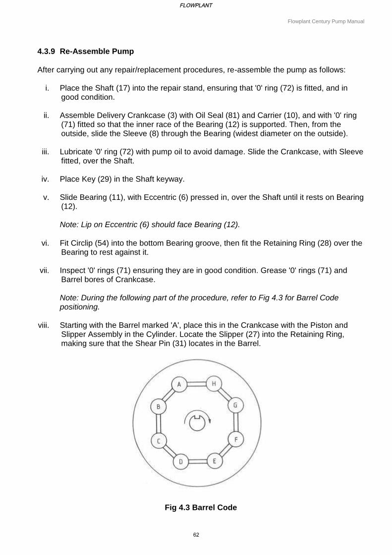
Flowplant Century Pump Manual
4.3.9 Re-Assemble Pump
After carrying out any repair/replacement procedures, re-assemble the pump as follows:
i. Place the Shaft (17) into the repair stand, ensuring that '0' ring (72) is fitted, and in good condition.
ii. Assemble Delivery Crankcase (3) with Oil Seal (81) and Carrier (10), and with '0' ring (71) fitted so that the inner race of the Bearing (12) is supported. Then, from the outside, slide the Sleeve (8) through the Bearing (widest diameter on the outside).
iii. Lubricate '0' ring (72) with pump oil to avoid damage. Slide the Crankcase, with Sleeve fitted, over the Shaft.
iv. Place Key (29) in the Shaft keyway.
v. Slide Bearing (11), with Eccentric (6) pressed in, over the Shaft until it rests on Bearing (12).
Note: Lip on Eccentric (6) should face Bearing (12).
vi. Fit Circlip (54) into the bottom Bearing groove, then fit the Retaining Ring (28) over the
Bearing to rest against it.
vii. Inspect '0' rings (71) ensuring they are in good condition. Grease '0' rings (71) and Barrel bores of Crankcase.
Note: During the following part of the procedure, refer to Fig 4.3 for Barrel Code positioning.
viii. Starting with the Barrel marked 'A', place this in the Crankcase with the Piston and
Slipper Assembly in the Cylinder. Locate the Slipper (27) into the Retaining Ring, making sure that the Shear Pin (31) locates in the Barrel.
Fig 4.3 Barrel Code
FLOWPLANT
62
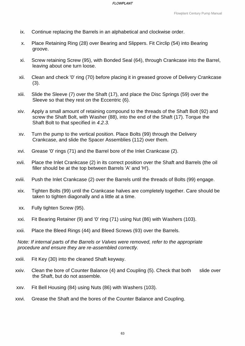
Flowplant Century Pump Manual
ix. Continue replacing the Barrels in an alphabetical and clockwise order.
x. Place Retaining Ring (28) over Bearing and Slippers. Fit Circlip (54) into Bearing groove.
xi. Screw retaining Screw (95), with Bonded Seal (64), through Crankcase into the Barrel, leaving about one turn loose.
xii. Clean and check '0' ring (70) before placing it in greased groove of Delivery Crankcase (3).
xiii. Slide the Sleeve (7) over the Shaft (17), and place the Disc Springs (59) over the Sleeve so that they rest on the Eccentric (6).
xiv. Apply a small amount of retaining compound to the threads of the Shaft Bolt (92) and screw the Shaft Bolt, with Washer (88), into the end of the Shaft (17). Torque the Shaft Bolt to that specified in 4.2.3.
xv. Turn the pump to the vertical position. Place Bolts (99) through the Delivery Crankcase, and slide the Spacer Assemblies (112) over them.
xvi. Grease '0' rings (71) and the Barrel bore of the Inlet Crankcase (2).
xvii. Place the Inlet Crankcase (2) in its correct position over the Shaft and Barrels (the oil filler should be at the top between Barrels 'A' and 'H').
xviii. Push the Inlet Crankcase (2) over the Barrels until the threads of Bolts (99) engage.
xix. Tighten Bolts (99) until the Crankcase halves are completely together. Care should be taken to tighten diagonally and a little at a time.
xx. Fully tighten Screw (95).
xxi. Fit Bearing Retainer (9) and '0' ring (71) using Nut (86) with Washers (103).
xxii. Place the Bleed Rings (44) and Bleed Screws (93) over the Barrels. Note: If internal parts of the Barrels or Valves were removed, refer to the appropriate procedure and ensure they are re-assembled correctly.
xxiii. Fit Key (30) into the cleaned Shaft keyway.
xxiv. Clean the bore of Counter Balance (4) and Coupling (5). Check that both slide over the Shaft, but do not assemble.
xxv. Fit Bell Housing (84) using Nuts (86) with Washers (103).
xxvi. Grease the Shaft and the bores of the Counter Balance and Coupling.
FLOWPLANT
63

Flowplant Century Pump Manual
xxvii. First push the Counter Balance on to the Shaft, then push the Coupling on to the Shaft.
xxviii. Fit Drive Cap (56) into the end of the Coupling, locating Pin (110) into the hole in the Shaft.
xxix. Put a small amount of retaining compound on Cap Screw (102) and tighten it into the Shaft.
xxx. Re-fit pump as detailed in Para 9 (Removal and Replacement of Pump Head.
4.3.10 Pump Running In
Prior to running in the pump after overhaul or major component replacement, the pump should be filled with oil to the correct level. Refer to Lubrication Chart (Table 4.2) for details of recommended oil types and pump oil capacities. The pump should also be bled of air in accordance with the procedures given in Sections 3.3.4, 3.3.5.
Note: Check the direction of pump rotation when first switched on.
Run the pump at maximum pressure for the following periods, whilst checking for leaks, monitoring the flow and checking the results against pump performance data:
a. Off load - 30 minutes
b. 1 /2 max. pressure - 60 minutes
c. Max. pressure - 60 minutes.
The following points should be taken into account when determining maximum pressure to be used when running in the pump:
Piston Size Maximum Pressure
22.5 mm 700 bar (10000 psi)
25.0 mm 550 bar (8000 psi)
27.5 mm 420 bar (6000 psi)
a. If the pump is being used on a system that has a lower working pressure than the maximum for the pump, then running in of the pump should be at the lower pressure.
b. Check the pump Identification Plate for the maximum working pressure of the pump before commencing the running in test. Some models of pumps have working pressures lower than stated, in which case running in should be carried out at the lower pressure.
FLOWPLANT
64
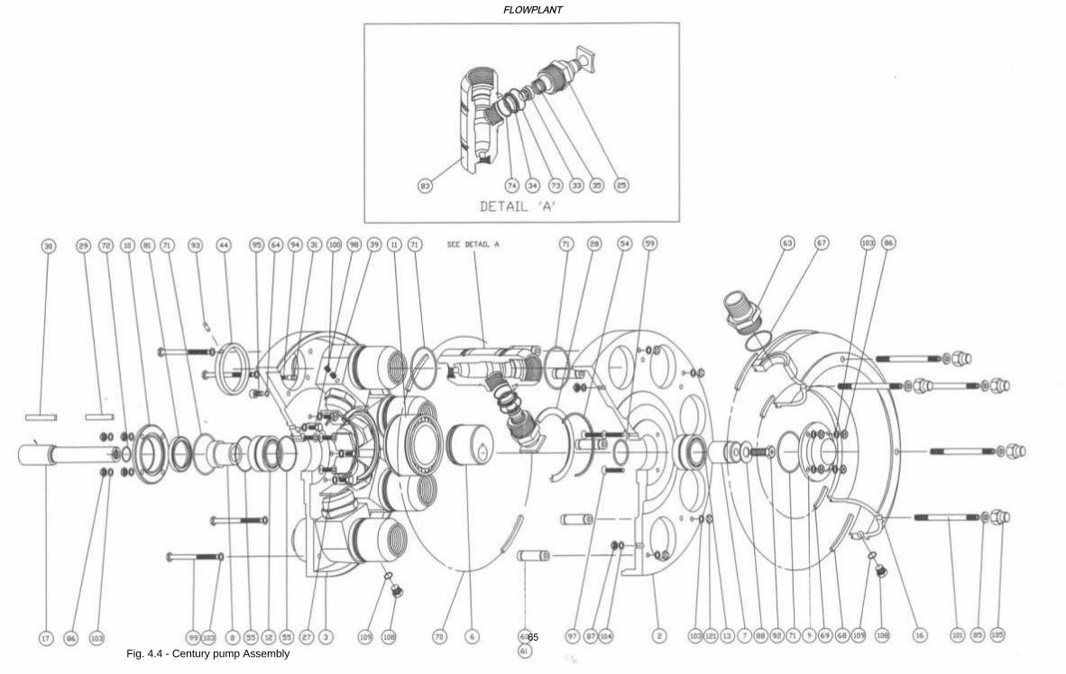
Fig. 4.4 - Century pump Assembly
FLOWPLANT
65
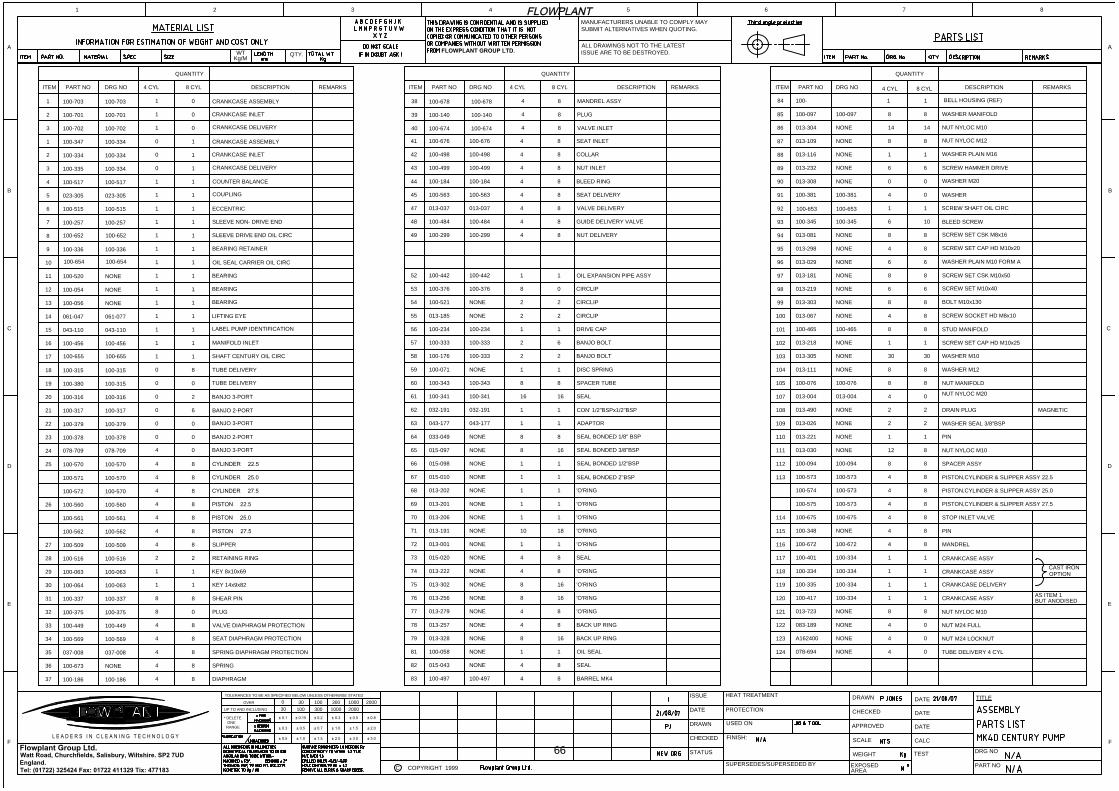
ITEM PART NO DRG NO
QUANTITY
DESCRIPTION REMARKS REMARKSDESCRIPTION
QUANTITY
ITEM PART NO DRG NO ITEM PART NO DRG NO
QUANTITY
DESCRIPTION REMARKS4 CYL 8 CYL 4 CYL 8 CYL
4 CYL 8 CYL
107013-004 013-004 4 0
NUT NYLOC M20
108013-490 NONE 2 2 DRAIN PLUG MAGNETIC
109013-026 NONE 2 2
WASHER SEAL 3/8"BSP
110 013-221 NONE 1 1 PIN
111 013-030 NONE 12 8 NUT NYLOC M10
112100-094 100-094 8 8 SPACER ASSY
113100-573 100-573 4 8
PISTON,CYLINDER & SLIPPER ASSY 22.5
100-574 100-573 4 8 PISTON,CYLINDER & SLIPPER ASSY 25.0
100-575 100-573 4 8 PISTON,CYLINDER & SLIPPER ASSY 27.5
114 100-675 100-675 4 8 STOP INLET VALVE
115100-348 NONE 4 8 PIN
116100-672 100-672 4 8 MANDREL
117100-401 100-334 1 1
CRANKCASE ASSY
118 100-334 100-334 1 1
CRANKCASE ASSY
119 100-335 100-334 1 1 CRANKCASE DELIVERY
120100-417 100-334 1 1
CRANKCASE ASSY
CAST IRON
OPTION
AS ITEM 1
BUT ANODISED
121013-723 NONE 8 8
NUT NYLOC M10
DRAWN
CHECKED
APPROVED
SCALE
WEIGHT
FINISH:
TITLE
DRG NO
PART NO
ISSUE
DATE
DRAWN
CHECKED
STATUS
TEST
WT
Kg/M
QTY.
EXPOSED
AREA
PROTECTION
USED ON
SUPERSEDES/SUPERSEDED BY
1999
Watt Road, Churchfields, Salisbury, Wiltshire. SP2 7UD
England.
Tel: (01722) 325424 Fax: 01722 411329 Tix: 477183
TOLERANCES TO BE AS SPECIFIED BELOW UNLESS OTHERWISE STATED
30UP TO AND INCLUDING
* DELETE
ONE
RANGE
OVER0
100 20001000300
30030 100 1000 2000
DATE
DATE
DATE
MANUFACTURERS UNABLE TO COMPLY MAY
SUBMIT ALTERNATIVES WHEN QUOTING.
ALL DRAWINGS NOT TO THE LATEST
ISSUE ARE TO BE DESTROYED.
Flowplant Group Ltd.
C COPYRIGHT
FLOWPLANT GROUP LTD.
A
B
C
D
E
F
21 3 4 5 6 7 8
B
C
D
E
F
CALC
L E A D E R S I N C L E A N I N G T E C H N O L O G Y
HEAT TREATMENT
122 083-189 NONE 4 0NUT M24 FULL
123 A162400 NONE 4 0NUT M24 LOCKNUT
124078-694 NONE 4 0
TUBE DELIVERY 4 CYL
11NONE013-11688
88NONE013-18197
100-076
NONE
NONE
NONE
100-465
NONE
NONE
NONE
013-218102
100-076
013-111
013-305
104
105
103
100-465
013-067
013-303
013-219
101
100
99
98
11
30
8
8
8
8
30
8
4
8
6
8
8
8
6
100-653
NONE
NONE
NONE
100-345
100-381
NONE
NONE
013-029
013-298
013-081
100-345
95
96
94
93
100-653
100-381
013-308
013-232
90
92
91
89
4
6
8
6
8
6
8
10
1
4
6
0
1
0
6
0
NONE
NONE
100-097
013-109
013-304
100-097
87
86
85
14
8
8
8
14
8
WASHER PLAIN M16
SCREW SET CSK M10x50
SCREW SET CAP HD M10x25
NUT MANIFOLD
WASHER M12
WASHER M10
STUD MANIFOLD
SCREW SOCKET HD M8x10
BOLT M10x130
SCREW SET M10x40
WASHER PLAIN M10 FORM A
SCREW SET CAP HD M10x20
SCREW SET CSK M8x16
BLEED SCREW
SCREW SHAFT OIL CIRC
SCREW HAMMER DRIVE
WASHER
WASHER M20
NUT NYLOC M12
NUT NYLOC M10
WASHER MANIFOLD
84 100- 1 1BELL HOUSING (REF)
BARREL MK4
SEAL
OIL SEAL11NONE100-05881
100-497100-497
015-04382
83
NONE 4
4
8
8
BACK UP RING
BACK UP RING
'O'RING
'O'RING
'O'RING
'O'RING
SEAL
'O'RING
'O'RING
'O'RING
'O'RING
'O'RING
SEAL BONDED 2"BSP
SEAL BONDED 1/2"BSP
SEAL BONDED 3/8"BSP
SEAL BONDED 1/8" BSP
ADAPTOR
013-328
013-257
013-279
79
78
77
NONE
NONE
NONE
013-256
013-302
013-222
015-020
013-001
74
76
75
73
72
NONE
NONE
NONE
NONE
NONE
8
4
4
16
8
8
4
8
8
4
1
8
16
16
8
1
043-177
NONE015-01067
013-191
013-206
013-201
013-202
71
70
69
68
NONE
NONE
NONE
NONE
015-098
015-097
033-049
043-177
65
66
64
63
NONE
NONE
NONE
11
10
1
1
1
18
1
1
1
8
1
8
1
16
1
8
1
CON' 1/2"BSPx1/2"BSP
SEAL
SPACER TUBE
DISC SPRING
BANJO BOLT
BANJO BOLT
DRIVE CAP
CIRCLIP
CIRCLIP
CIRCLIP
OIL EXPANSION PIPE ASSY
NUT DELIVERY
GUIDE DELIVERY VALVE
VALVE DELIVERY
08100-376100-37653
032-191
100-341
100-343
100-333
100-333
100-234
100-17658
032-191
100-341
100-343
100-071
60
62
61
59 NONE
100-333
100-234
013-185
100-521
57
56
55
54
NONE
NONE
22
8
1
16
1
8
1
16
1
2
1
2
2
6
1
2
2
100-442
100-299
100-484
013-037
100-442
100-299
52
49
100-484
013-037
48
47
1
4
1
8
4
4
8
8
SEAT DELIVERY
BLEED RING
NUT INLET
COLLAR
SEAT INLET
84100-184100-18444
100-563100-56345 4 8
100-499
100-498
100-676
100-499
100-498
100-676
43
42
41
4
4
4
8
8
8
VALVE INLET
PLUG
MANDREL ASSY
40 100-674
38
39
100-678
100-140
100-674
100-140
100-678
4
4
4
8
8
8
DIAPHRAGM
SPRING
SPRING DIAPHRAGM PROTECTION
SEAT DIAPHRAGM PROTECTION
VALVE DIAPHRAGM PROTECTION
PLUG
SHEAR PIN
KEY 14x9x82
KEY 8x10x69
RETAINING RING
SLIPPER
84
100-186100-18637
36
35
100-673
037-008
34
33
100-569
100-449
NONE
037-008
100-569
100-449
100-06430
31
32
100-337
100-375
29
28
100-063
100-516
100-063
100-375
100-337
100-063
100-516
4
4
4
4
8
8
8
8
1
8
8
1
2
1
8
0
1
2
100-570100-572
27100-509
100-562
26 100-560
100-561
100-509
100-562
100-561
100-560
25
100-571
100-570
100-570
100-570
84
4
4
4
4
8
8
8
8
4
4
8
8
BANJO 3-PORT
BANJO 2-PORT
24
23
078-709
100-378
078-709
100-378
4
0
0
0
SHAFT CENTURY OIL CIRC
BANJO 3-PORT
BANJO 2-PORT
BANJO 3-PORT
TUBE DELIVERY
TUBE DELIVERY
MANIFOLD INLET
LABEL PUMP IDENTIFICATION
LIFTING EYE
BEARING
BEARING
BEARING
OIL SEAL CARRIER OIL CIRC
BEARING RETAINER
SLEEVE DRIVE END OIL CIRC
SLEEVE NON- DRIVE END
ECCENTRIC
COUPLING
COUNTER BALANCE
CRANKCASE DELIVERY
CRANKCASE INLET
CRANKCASE ASSEMBLY
11
100-517100-5174
11
NONE100-05613
100-315100-31518
100-31620
22
21
100-379
100-317
19 100-380
100-316
100-379
100-317
100-315
17
16
100-655
100-456
15
14
043-110
061-047
100-655
100-456
043-110
061-077
80
0
0
0
0
2
0
6
0
1
1
1
1
1
1
1
1
100-654
100-52011
12100-054
10
9 100-336
NONE
NONE
100-654
100-336
100-5156
8
7
100-652
100-257
5 023-305
100-515
100-652
100-257
023-305
1
1
1
1
1
1
1
1
1
1
1
1
1
1
1
1
3
2
100-335
100-334
1 100-347
100-334
100-334
100-334
0
0
0
1
1
1
CRANKCASE ASSEMBLY
CRANKCASE INLET
CRANKCASE DELIVERY
01
100-703100-7031
100-7023
2 100-701
100-702
100-701
1
1
0
0
FLOWPLANT
66
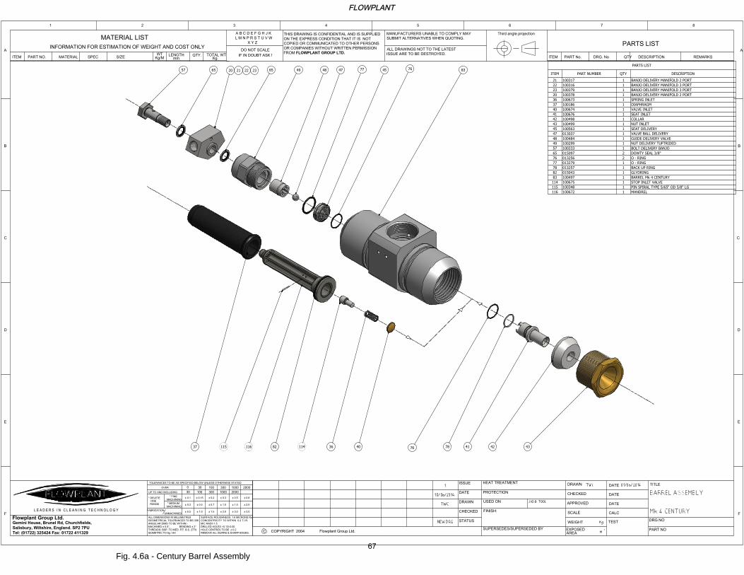
PARTS LIST
DESCRIPTIONQTYPART NUMBERITEM
BANJO DELIVERY MANIFOLD 2 PORT110031721
BANJO DELIVERY MANIFOLD 3 PORT110031622
BANJO DELIVERY MANIFOLD 3 PORT110037923
BANJO DELIVERY MANIFOLD 2 PORT110037820
SPRING INLET110067336
DIAPHRAGM110018637
VALVE INLET110067440
SEAT INLET110067641
COLLAR110049842
NUT INLET110049943
SEAT DELIVERY110056345
VALVE BALL DELIVERY101303747
GUIDE DELIVERY VALVE110048448
NUT DELIVERY TUFTRIDED110029949
BOLT DELIVERY BANJO110033357
DOWTY SEAL 3/8"201509765
O - RING201325676
O - RING101327977
BACK UP RING101325778
GLYDRING101504382
BARREL Mk 4 CENTURY110049783
STOP INLET VALVE1100675114
PIN SPIRAL TYPE 5/65" OD 5/8" LG1100348115
MANDREL1100672116
2004
DRAWN
CHECKED
APPROVED
SCALE
WEIGHT
FINISH:
TITLE
DRG NO
PART NO
ISSUE
DATE
DRAWN
CHECKED
STATUS
TEST
INFORMATION FOR ESTIMATION OF WEIGHT AND COST ONLY
MATERIAL LIST
ITEM PART NO. MATERIAL SPEC SIZE
WT
mm Kg
Kg/M
LENGTH TOTAL WTQTY.
PARTS LIST
ITEM PART No. DRG. No QTY DESCRIPTION REMARKS
EXPOSED
AREA
PROTECTION
USED ON
SUPERSEDES/SUPERSEDED BY
A B C D E F G H J K
L M N P R S T U V W
X Y Z
Gemini House, Brunel Rd, Churchfields,
Salisbury, Wiltshire, England. SP2 7PU
Tel: (01722) 325424 Fax: 01722 411329
ALL DIMENSIONS IN MILLIMETRES
GEOMETRICAL TOLERANCES TO BS 308
ANGULAR DIMS TO BE WITHIN:-
MACHINED 0.5 , BENDING 2
THREADS: BSP, TO MED. FIT. B.S. 2779
ISOMETRIC TO 6g / 6H
TOLERANCES TO BE AS SPECIFIED BELOW UNLESS OTHERWISE STATED
30UP TO AND INCLUDING
FABRICATION
UNMACHINED
* DELETE
ONE
RANGE
0.5
* MEDIUM
MACHINING
* FINE
MACHINING
0.3
0.1
OVER0
100 20001000300
SURFACE ROUGHNESS: 1.6 MICRONS Ra
CONCENTRICITY TO WITHIN 0.2 T.I.R.
M/C RADII 1.5
DRILLED HOLES +0.13/-0.00
HOLE CENTRES TO BE 0.2
REMOVE ALL BURRS & SHARP EDGES.
2.0
1.0
0.3
1.0 1.5
0.5
0.15
0.7
0.2
3.0 3.0
1.5
0.5
2.0
0.8
30030
100 1000 2000
DATE
DATE
DATE
DO NOT SCALE
IF IN DOUBT ASK !
MANUFACTURERS UNABLE TO COMPLY MAY
SUBMIT ALTERNATIVES WHEN QUOTING.
ALL DRAWINGS NOT TO THE LATEST
ISSUE ARE TO BE DESTROYED.
Flowplant Group Ltd.
C COPYRIGHT Flowplant Group Ltd.
THIS DRAWING IS CONFIDENTIAL AND IS SUPPLIED
ON THE EXPRESS CONDITION THAT IT IS NOT
COPIED OR COMMUNICATED TO OTHER PERSONS
OR COMPANIES WITHOUT WRITTEN PERMISSION
FROM FLOWPLANT GROUP LTD.
A
B
C
D
E
F
21 3 4 5 6 7 8
A
B
C
D
E
F
CALC
Third angle projection
L E A D E R S I N C L E A N I N G T E C H N O L O G Y
HEAT TREATMENT
43424178
76
40361148211611537
57 65
20 21 22 23
65 48 47
77
45
76
8349
Fig. 4.6a - Century Barrel Assembly
FLOWPLANT
67
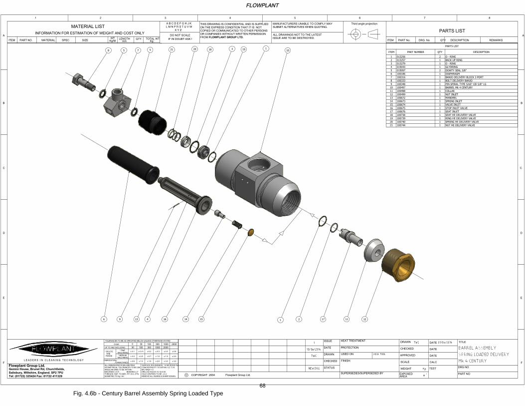
PARTS LIST
DESCRIPTIONQTYPART NUMBERITEM
O - RING20132561
BACK UP RING10132572
O - RING10132793
GLYDRING10150434
DOWTY SEAL 3/8"20150975
DIAPHRAGM11001866
BANJO DELIVERY BLOCK 3 PORT11003167
BOLT DELIVERY BANJO11003338
PIN SPIRAL TYPE 5/65" OD 5/8" LG11003489
BARREL Mk 4 CENTURY110049710
COLLAR110049811
NUT INLET110049912
MANDREL110067213
SPRING INLET110067314
VALVE INLET110067415
STOP INLET VALVE110067516
SEAT INLET110067617
SEAT HE DELIVERY VALVE110073818
RING HE DELIVERY VALVE110073919
SPRING HE DELIVERY VALVE110074020
NUT HE DELIVERY VALVE110074421
2004
DRAWN
CHECKED
APPROVED
SCALE
WEIGHT
FINISH:
TITLE
DRG NO
PART NO
ISSUE
DATE
DRAWN
CHECKED
STATUS
TEST
INFORMATION FOR ESTIMATION OF WEIGHT AND COST ONLY
MATERIAL LIST
ITEM PART NO. MATERIAL SPEC SIZE
WT
mm Kg
Kg/M
LENGTH TOTAL WTQTY.
PARTS LIST
ITEM PART No. DRG. No QTY DESCRIPTION REMARKS
EXPOSED
AREA
PROTECTION
USED ON
SUPERSEDES/SUPERSEDED BY
A B C D E F G H J K
L M N P R S T U V W
X Y Z
Gemini House, Brunel Rd, Churchfields,
Salisbury, Wiltshire, England. SP2 7PU
Tel: (01722) 325424 Fax: 01722 411329
ALL DIMENSIONS IN MILLIMETRES
GEOMETRICAL TOLERANCES TO BS 308
ANGULAR DIMS TO BE WITHIN:-
MACHINED 0.5 , BENDING 2
THREADS: BSP, TO MED. FIT. B.S. 2779
ISOMETRIC TO 6g / 6H
TOLERANCES TO BE AS SPECIFIED BELOW UNLESS OTHERWISE STATED
30UP TO AND INCLUDING
FABRICATION
UNMACHINED
* DELETE
ONE
RANGE
0.5
* MEDIUM
MACHINING
* FINE
MACHINING
0.3
0.1
OVER0
100 20001000300
SURFACE ROUGHNESS: 1.6 MICRONS Ra
CONCENTRICITY TO WITHIN 0.2 T.I.R.
M/C RADII 1.5
DRILLED HOLES +0.13/-0.00
HOLE CENTRES TO BE 0.2
REMOVE ALL BURRS & SHARP EDGES.
2.0
1.0
0.3
1.0 1.5
0.5
0.15
0.7
0.2
3.0 3.0
1.5
0.5
2.0
0.8
30030 100 1000 2000
DATE
DATE
DATE
DO NOT SCALE
IF IN DOUBT ASK !
MANUFACTURERS UNABLE TO COMPLY MAY
SUBMIT ALTERNATIVES WHEN QUOTING.
ALL DRAWINGS NOT TO THE LATEST
ISSUE ARE TO BE DESTROYED.
Flowplant Group Ltd.
C COPYRIGHTFlowplant Group Ltd.
THIS DRAWING IS CONFIDENTIAL AND IS SUPPLIED
ON THE EXPRESS CONDITION THAT IT IS NOT
COPIED OR COMMUNICATED TO OTHER PERSONS
OR COMPANIES WITHOUT WRITTEN PERMISSION
FROM FLOWPLANT GROUP LTD.
A
B
C
D
E
F
21 3 4 5 6 7 8
A
B
C
D
E
F
CALC
Third angle projection
L E A D E R S I N C L E A N I N G T E C H N O L O G Y
HEAT TREATMENT
8 5 7
5
21
20
18
19
10
1211172
1
15141641396
3
1
Fig. 4.6b - Century Barrel Assembly Spring Loaded Type
FLOWPLANT
68
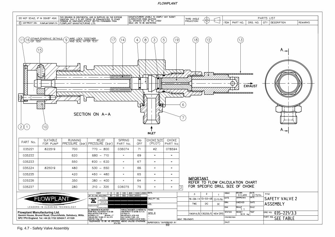
* FINE
MACHINING
FABRICATION
UNMACHINED
* MEDIUM
MACHINING
Flowplant Manufacturing Ltd.
Gemini House, Brunel Road, Churchfields, Salisbury, Wilts.
SP2 7PU England. Tel: +44 (0) 1722 325424 F. 411329
L E A D E R S I N C L E A N I N G T E C H N O L O G Y
Fig. 4.7 - Safety Valve Assembly
FLOWPLANT
69
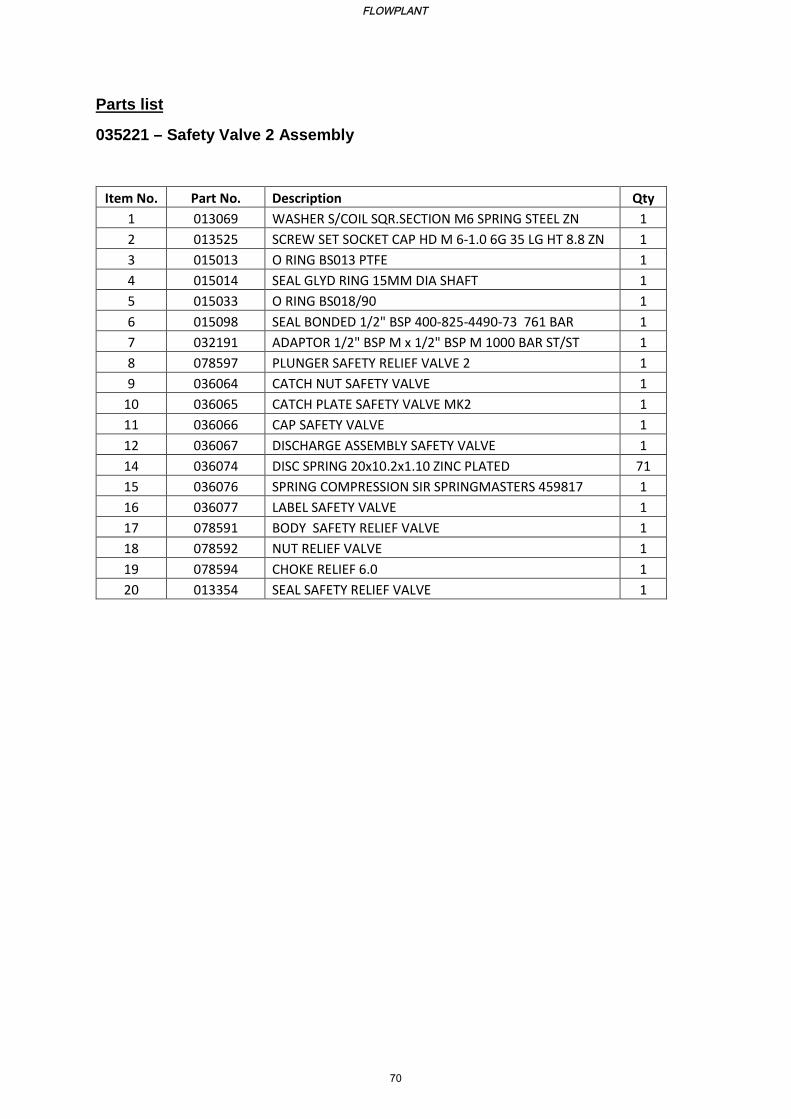
Parts list
035221 – Safety Valve 2 Assembly
Item No. Part No. Description Qty
1 013069 WASHER S/COIL SQR.SECTION M6 SPRING STEEL ZN 1
2 013525 SCREW SET SOCKET CAP HD M 6-1.0 6G 35 LG HT 8.8 ZN 1
3 015013 O RING BS013 PTFE 1
4 015014 SEAL GLYD RING 15MM DIA SHAFT 1
5 015033 O RING BS018/90 1
6 015098 SEAL BONDED 1/2" BSP 400-825-4490-73 761 BAR 1
7 032191 ADAPTOR 1/2" BSP M x 1/2" BSP M 1000 BAR ST/ST 1
8 078597 PLUNGER SAFETY RELIEF VALVE 2 1
9 036064 CATCH NUT SAFETY VALVE 1
10 036065 CATCH PLATE SAFETY VALVE MK2 1
11 036066 CAP SAFETY VALVE 1
12 036067 DISCHARGE ASSEMBLY SAFETY VALVE 1
14 036074 DISC SPRING 20x10.2x1.10 ZINC PLATED 71
15 036076 SPRING COMPRESSION SIR SPRINGMASTERS 459817 1
16 036077 LABEL SAFETY VALVE 1
17 078591 BODY SAFETY RELIEF VALVE 1
18 078592 NUT RELIEF VALVE 1
19 078594 CHOKE RELIEF 6.0 1
20 013354 SEAL SAFETY RELIEF VALVE 1
FLOWPLANT
70
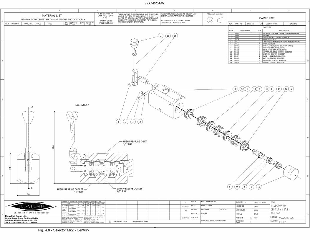
SECTION A-A
A
A
PARTS LIST
DESCRIPTIONQTYPART NUMBERITEM
PIN SPIRAL TYPE 8MM X 16MM LG STAINLESS STEEL.20140071
PIN CLEVIS10140082
CLIP CLEVIS MK2 CENTURY SELECTOR10140093
O RING BS016 PTFE10150214
STEP SEAL 19.0MM DIA SHAFT C/W BS111/90 O RING20150225
O RING BS027/9040150236
KNOB PLASTIC 1032 M8 (SELECTOR LEVER)10230027
BODY MK2 CENTURY SELECTOR10360208
SPINDLE MK2 CENTURY SELECTOR10360219
NUT RETAINING MK2 CENTURY SELECTOR103602210
LEVER MK2 CENTURY SELECTOR103602311
GLAND MK2 CENTURY SELECTOR203602412
SEAT MK2 CENTURY SELECTOR203602513
COLLAR MK2 CENTURY SELECTOR303602614
LINK MK2 CENTURY SELECTOR103602715
2004
DRAWN
CHECKED
APPROVED
SCALE
WEIGHT
FINISH:
TITLE
DRG NO
PART NO
ISSUE
DATE
DRAWN
CHECKED
STATUS
TEST
INFORMATION FOR ESTIMATION OF WEIGHT AND COST ONLY
MATERIAL LIST
ITEM PART NO. MATERIAL SPEC SIZE
WT
mm Kg
Kg/M
LENGTH TOTAL WTQTY.
PARTS LIST
ITEM PART No. DRG. No QTY DESCRIPTION REMARKS
EXPOSED
AREA
PROTECTION
USED ON
SUPERSEDES/SUPERSEDED BY
A B C D E F G H J K
L M N P R S T U V W
X Y Z
Gemini House, Brunel Rd, Churchfields,
Salisbury, Wiltshire, England. SP2 7PU
Tel: (01722) 325424 Fax: 01722 411329
ALL DIMENSIONS IN MILLIMETRES
GEOMETRICAL TOLERANCES TO BS 308
ANGULAR DIMS TO BE WITHIN:-
MACHINED 0.5 , BENDING 2
THREADS: BSP, TO MED. FIT. B.S. 2779
ISOMETRIC TO 6g / 6H
TOLERANCES TO BE AS SPECIFIED BELOW UNLESS OTHERWISE STATED
30UP TO AND INCLUDING
FABRICATION
UNMACHINED
* DELETE
ONE
RANGE
0.5
* MEDIUM
MACHINING
* FINE
MACHINING
0.3
0.1
OVER0
100 20001000300
SURFACE ROUGHNESS: 1.6 MICRONS Ra
CONCENTRICITY TO WITHIN 0.2 T.I.R.
M/C RADII 1.5
DRILLED HOLES +0.13/-0.00
HOLE CENTRES TO BE 0.2
REMOVE ALL BURRS & SHARP EDGES.
2.0
1.0
0.3
1.0 1.5
0.5
0.15
0.7
0.2
3.0 3.0
1.5
0.5
2.0
0.8
30030 100 1000 2000
DATE
DATE
DATE
DO NOT SCALE
IF IN DOUBT ASK !
MANUFACTURERS UNABLE TO COMPLY MAY
SUBMIT ALTERNATIVES WHEN QUOTING.
ALL DRAWINGS NOT TO THE LATEST
ISSUE ARE TO BE DESTROYED.
Flowplant Group Ltd.
C COPYRIGHTFlowplant Group Ltd.
THIS DRAWING IS CONFIDENTIAL AND IS SUPPLIED
ON THE EXPRESS CONDITION THAT IT IS NOT
COPIED OR COMMUNICATED TO OTHER PERSONS
OR COMPANIES WITHOUT WRITTEN PERMISSION
FROM FLOWPLANT GROUP LTD.
A
B
C
D
E
F
21 3 4 5 6 7 8
A
B
C
D
E
F
CALC
Third angle projection
L E A D E R S I N C L E A N I N G T E C H N O L O G Y
HEAT TREATMENT
60
196
82
109 55 4
12 61413 613 612 68
7 11 15
2131
HIGH PRESSURE INLET
1/2" BSP
LOW PRESSURE OUTLET
1/2" BSP
HIGH PRESSURE OUTLET
1/2" BSP
Fig. 4.8 - Selector Mk2 - Century
FLOWPLANT
71
Section 5
Warranty
FLOWPLANT
72
Section 5
Warranty
Contents
Section Page
5.1 Flowplant Warranty 74
5.2 Limited Warranty Policy 75
5.2.1 Non Warranty Items 75
5.2.2 Service and Spares 78
FLOWPLANT
73

Flowplant Century Pump Manual
5.1 FLOWPLANT WARRANTY
Warranty of new products: Equipment manufactured and supplied by Flowplant is warranted to be free from defects in materials and workmanship. The warranty includes both parts and labour necessary to correct any such defects. The warranty period for new products is 12 months from date of despatch from our factory or 2000 operating hours, whichever occurs soonest. We shall repair or, at our option, replace free of charge any product, part(s) or component(s) manufactured by Flowplant which fail due to faulty manufacture or material within the warranty period.
Warranty of spare parts: The warranty for new spare parts is 6 months from date of despatch on materials and workmanship or 250 operating hours, whichever occurs soonest.
The warranty for reconditioned spare parts is 90 days from date of despatch on materials and workmanship.
Provided always that
a) They are returned to Flowplant for inspection (carriage paid), along with a copy of the original part(s) sale invoice (where necessary); and
b) All terms agreed by Flowplant for payment of such goods have been complied with; and
c) If a defect/failure is discovered before the expiration of the warranty, notification must be given to the Flowplant service department immediately
d) Any claim hereunder is made within 30 days of the date of discovery of the defect/failure.
Provision of this warranty shall not apply to any Flowplant product which has been:
a) Used for a purpose for which it is not designed for; or
b) Applied to a use which has not been approved by Flowplant; or
c) Subject to misuse, negligence, lack of maintenance or accident; or
d) Repaired or altered in any way so as, in the judgment of Flowplant, to adversely affect its performance and reliability
FLOWPLANT
74
Flowplant Century Pump Manual
5.2 LIMITATIONS OF THE WARRANTY
The new product and spare parts warranty is limited to defects in material or workmanship of the product. It does not cover loss of time, inconvenience, property damage or any consequential damages. Repair or replacement of the product is your exclusive remedy.
Our liability under this clause shall be in lieu and to this exclusion of any warranty or conditions implied or expressed by law as to the quality or fitness for purpose of any goods supplied hereunder PROVIDED THAT nothing in this clause shall operate so as to exclude liability for death or personal injury arising from the negligence of the company or its employees.
Our obligations as aforesaid shall constitute the full extent of our liability in respect of any loss or damage sustained by the purchaser whether caused by any breach of this contract or by our negligence or otherwise and we shall not be liable to make good or pay for loss of use of the goods, loss of revenue, loss of profit or goodwill or any direct or consequential losses howsoever caused and the purchaser undertakes to indemnify us against any such claims against us by third parties.
On order to comply with the provision of the Health and Safety at work etc., Act 1974 in respect of articles manufactured, supplied or installed for use at work we test all our products before they leave our factory and supply them with adequate instructions for their proper use. Further copies of these instructions are available from us upon request.
5.2.1 Non Warranty Items
The Warranty terms are a precise statement of Flowplant Group Ltd's intention to cover the replacement or repair cost, on a standardised and agreed basis, of any product failure resulting from defective material or sub-standard workmanship during the manufacturing process. The following items are considered to be of a Maintenance nature and should not be subject of a claim.
Engine (Manufacturers Warranty Applies)
Routine servicing of injector/fuel injection equipment.
Heavy fuel consumption rectified by engine adjustment.
Adjustment of fan belts/throttle and controls.
Tightening of all sump and cover bolt/nuts water connections and exterior oilpipes and filter bolts.
Filters and the cleaning of filters.
Engine service components.
Adjustments.
FLOWPLANT
75
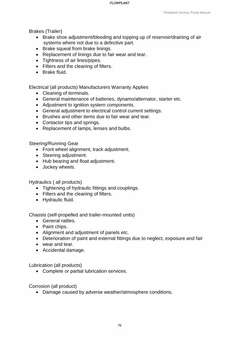
Flowplant Century Pump Manual
Brakes (Trailer)
Brake shoe adjustment/bleeding and topping up of reservoir/draining of air systems where not due to a defective part.
Brake squeal from brake linings.
Replacement of linings due to fair wear and tear.
Tightness of air lines/pipes.
Filters and the cleaning of filters.
Brake fluid.
Electrical (all products) Manufacturers Warranty Applies
Cleaning of terminals.
General maintenance of batteries, dynamo/alternator, starter etc.
Adjustment to ignition system components.
General adjustment to electrical control current settings.
Brushes and other items due to fair wear and tear.
Contactor tips and springs.
Replacement of lamps, lenses and bulbs.
Steering/Running Gear
Front wheel alignment, track adjustment.
Steering adjustment.
Hub bearing and float adjustment.
Jockey wheels.
Hydraulics ( all products)
Tightening of hydraulic fittings and couplings.
Filters and the cleaning of filters.
Hydraulic fluid.
Chassis (self-propelled and trailer-mounted units)
General rattles.
Paint chips.
Alignment and adjustment of panels etc.
Deterioration of paint and external fittings due to neglect, exposure and fair
wear and tear.
Accidental damage.
Lubrication (all products)
Complete or partial lubrication services.
Corrosion (all product)
Damage caused by adverse weather/atmosphere conditions.
FLOWPLANT
76
Flowplant Century Pump Manual
General (all products)
Fair wear and tear.
Any work carried out to improve the general finish of the machine above
what is known to be the factory standard.
Failure to maintain the equipment in accordance with the manufacturers reccomendations.
In order to comply with the provisions of the Health and Safety at Work Act 1974 in respect of articles manufactured, supplied or installed for use at work, we test all our products before they leave our factory and supply with them adequate instructions for their proper use. Further copies of these instructions are available from us on request. We shall not be liable for loss, injury or damage of whatever nature caused by goods, design, technical information, suggestions, etc supplied by us where as the case maybe they have been structurally modified or misused or misapplied or have not been properly cared for and maintained, and the purchaser hereby agrees to indemnify us against all such claims and demands or by whomsoever they are brought.
REMEMBER:
i. The replacement or repair of tyres is not covered by the Company’s warranty terms. ii. In the case of van and truck mounted equipment the warranty relating to the actual
vehicle remains the responsibility of the vehicle manufacturer or supplier.
FLOWPLANT
77
Flowplant Century Pump Manual
5.2.2 Service and Spares
Flowplant provide service and spares cover in most parts of the world. When ordering spares, please quote:-
a) Your company name and address. b) Destination of parts, if different. c) Description and part number. d) Quantity required. e) Price and method of payment. f) Delivery date. g) Order number. h) Confirmation of order.
When requesting service or repairs, please state:-
a) Your company name and address. b) Location of machine/unit if different from above. c) Type and model of machine/unit. d) Pump serial number. e) Problem(s) with machine/unit. f) Availability of machine/unit for service or repairs. g) Date of service and site contract. h) Cost and method of payment. i) Order number. j) Confirmation of order.
FLOWPLANT
78