HANDRIL CALCULATION
11
STRUCTURAL ANALYSIS TEAM BOMBARDIER TRANSPORTATION MEXICO (SAT-BTM) SAT-BTM Development Training Process Passageway Handrail Calculations Contrato No. 248 Preparado : Gonzalo Anzaldo/Omar Cuevas/ Óscar Sosa/Fernando Hernández/Gustavo Nava/José Armando Rosas Project Engineers Revisado : George Bursuc Engineering Expert
-
Upload
gonzalo-anzaldo -
Category
Documents
-
view
8 -
download
1
description
STRUCTURAL ANALYSIS
Transcript of HANDRIL CALCULATION

STRUCTURAL ANALYSIS TEAM BOMBARDIER TRANSPORTATION MEXICO (SAT-BTM)
SAT-BTM Development Training Process
Passageway Handrail Calculations
Contrato No. 248
Preparado :
Gonzalo Anzaldo/Omar Cuevas/Óscar Sosa/Fernando Hernández/Gustavo
Nava/José Armando RosasProject Engineers
Revisado : George BursucEngineering Expert
Aprobado : George BursucEngineering Expert
Nombre / Titulo, Grupo Firma Fecha
Documento No. SAT-BRA-0001 Rev. 0La información, datos técnicos y diseños contenidos en este documento son de propiedad exclusiva de Bombardier Inc. o contienen derechos de propiedad de otros y no está permitido su uso sin el consentimiento escrito de Bombardier Inc. Fecha 13/03/15
(dd/mm/aa)

Passageway Handrail Calculations SAT-BRA-0001 Revisión: 0
Revisiones del Documento
RevisionFecha
(dd.mm.aa) Descripción de los Cambios
00 18.03.2015 Emisión Original
Bombardier 2015 Página i

Passageway Handrail Calculations SAT-BRA-0001 Revisión: 0
Contenido
1. Objective.....................................................................................................................................................................................2
2. Calculation report........................................................................................................................................................................2
3. project conclusions......................................................................................................................................................................5
4. anexe & tables.............................................................................................................................................................................5
Bombardier 2015 Página ii

Passage way Handrail Calculations 820-BRA-0010 Revisión: 0
1. OBJECTIVE
Throughout this evaluation process, we are defining the amount of bolts, and their diameters according to the specific geometry on the handrail, and the two main load cases defined for this purpose.
The load cases are representing the maximum revenue service condition, and will help to determine the type, size, and number of attachments to keep in place the hand rail.
2. CALCULATION REPORT.
For the analysis, the boundary conditions for the Passageway Handrail are:
- Fixed support (both supports for the handrail).- Load in the center of the member BC (1127 N).
The method solution for the frame is the distribution of moments (Cross method). For the first step, calculated the distribution factor (DF) for every element in the frame:
Element DFDFAB 0DFDC 0DFBA 0.838DFCD 0.838DFBC 0.161DFCB 0.161
The fixed extreme moments (FEM) for every element in the frame are:
Element FEMFEMAB 0FEMBA 0FEMBC -122.074FEMCB 122.074FEMCD 0FEMDC 0
With DF and FEM values, used the table to determinate the moments in fixed support:
JOINT A B C D
MEM AB BA BC CB CD DCDF 0 0.839 0.161 0.161 0.839 0
FEM -122.074 122.0741 102.385 19.689 -19.689 -102.385
51.192 -9.845 9.845 -51.1922 8.257 1.588 -1.588 -8.257
4.128 -0.794 0.794 -4.128
2

Passage way Handrail Calculations 820-BRA-0010 Revisión: 0
3 0.666 0.128 -0.128 -0.6660.333 -0.064 0.064 -0.333
4 0.009 0.010 -0.010 -0.009 ∑ 55.654 112.155 -111.200 111.523 -110.478 -55.654
Thus, with the moments and from the free-body diagrams:
ELEMENT FORCE (CASE I, II)AX 671.235 NAY 563.5 NBX 671.235 NBY 563.5 N
According to the results for the first and second case of study (direction for the force in the frame, BC element), the values for reactions in A and B are the same, but the direction is opposite.
For this exercise, used bolts grade 1; the properties for this bolt type are:
Grade 1Sp (ksi) 33000Sy (ksi) 36000Su (ksi) 60000
The parameters are:
Parameters:External force Total (FeT) (N) 563.5
V (shear) (N) 671.3302064No. Bolts 2
Safety factor (S.F) 2
To obtain the diameter for bolt:
External force (N) 281.75External force (lbf) 63.339
At (with d < 3/4 in) 0.0481
From tables, used a size of 5/16:
3

Passage way Handrail Calculations 820-BRA-0010 Revisión: 0
To determinate the safety factor (SF), first calculated the clamping force (Fi) and the elastic constants for bolts and parts to be joined (the proposal for safety factor is 3):
Clamping forceSi (ksi) 90
Fi (lbf) 2322
The elastic constants for bolsts are:
Elastic constantsKb (lbf/in) 517357
Kc (lbf/in)5585749
With these values, the separation factor is:
N sep=40.054>2.0Finally, determinate the safety factor:
Safety factor (S.F):Nf 62.230
V 335.665
Ns 3.245
4

Passage way Handrail Calculations 820-BRA-0010 Revisión: 0
N 3.240
Them:NSF=3.240>2.0
The torque for the bolt is:
Torque:K (lubricated bolts) 0.18
T T=K id F i 80.886
To determinate the adjustment moment for bolt, have:
Adjustment moment:P (from tables) 0.049
As (in^2) AS=
π4
(d−0.938P )20.055
FM FM=0.9RP AS 3008.401
µ (from tables) 0.15MG
MG=FM ( d2 )( Pπd +1.155μ) 105.001
Finally, to determinated the torque created by the friction in the screw head is:
Torque by the friction
dw (in) (from tables) 0.511dh (in) (from tables) 0.312
DKM (in)DKM=
dW+dh2
0.412
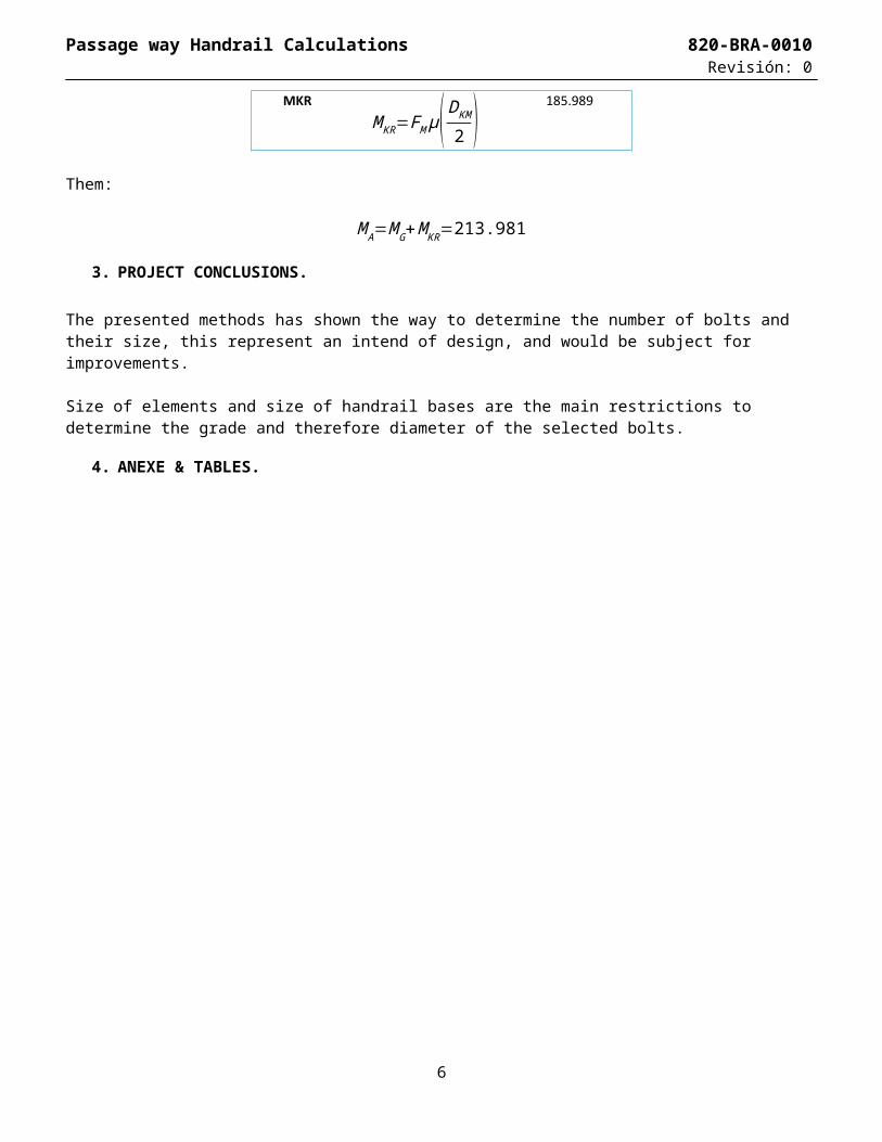
µ (from tables) 0.3MKR
MKR=FM μ( DKM
2 ) 185.989
Them:
M A=MG+MKR=213.981
3. PROJECT CONCLUSIONS.
The presented methods has shown the way to determine the number of bolts and their size, this represent an intend of design, and would be subject for improvements.
Size of elements and size of handrail bases are the main restrictions to determine the grade and therefore diameter of the selected bolts.
5

Passage way Handrail Calculations 820-BRA-0010 Revisión: 0
4. ANEXE & TABLES.
6
Passage way Handrail Calculations 820-BRA-0010 Revisión: 0
7