
Handling and Installation - Reus · Product Catalogue, e.g. stress levels, installation methods,...
414
Handling & Installation Version 2018.01
Transcript of Handling and Installation - Reus · Product Catalogue, e.g. stress levels, installation methods,...
Handling & InstallationVersion 2018.01


LOGSTOR A/S · Tel. +45 99 66 10 00 Handling and Installation 2009.07
1.0.0.1
Introduction
Contents
GeneralOverview
This section contains a presentation of the Handling and Installation Manual and some of the most essential conditions for handling, adaption and installation of preinsulated pipes under different installation situations and conditions.
- The Manual 1.1- Storage and transport 1.2- Excavation, installation and backfilling of trench 1.3- Cutting and adaption of pipes 1.4- Winter measures 1.5
Handling and Installation · 2009.07 LOGSTOR A/S · Tel. +45 99 66 10 00
1.1.0.1
GeneralThe Manual
Manuals
This manual The Handling and Installation Manual is a tool, serving the following purposes:
- Enable the contractor to carry out trenches, anchors and the like, so pipes, joints etc. are correctly installed and the system protected against unintentional influences.
- Enable fitters to install pipes and other components so the system works unproblematic during its service time.
- Enable supervisors to make quality checks so the system which the customer buys is made in accordance with LOGSTOR’s general guidelines.Naturally, requirements from local authorities must be taken into account.
If nothing else is stated, the instructions of this manual are based on the conditions in the Product Catalogue, e.g. stress levels, installation methods, temperature ranges etc.
The manual describes general installation instructions. If the installation situation deviates from the conditions in the manual, please contact LOGSTOR’s technicians.
Please note! The three manuals are independent works. Consequently, the numbering of the manuals lacks coherence.
Besides serving as a reference, the page numbering also serves as an order No., as we can offer to tailor product as well as project specific manuals.
This manual is volume 3 of LOGSTOR A/S’s manual collection which at present consists of:
· Product Catalogue· Design Manual· Handling and Installation Manual
LOGSTOR A/S · Tel. +45 99 66 10 00 Handling and Installation · 2009.07
Use of themanual
No part of the manual may be reproduced for external use without the express written permis-sion of LOGSTOR.
The information/instructions are general. Application and implementation must take place with due respect to local conditions.
Additional/specific information can be achieved from our technicians.
All rights reserved. The English version of the LOGSTOR manual is the master/pattern copy whereas the other copies are translations, made according to the best knowledge of the translators.
The information in this document is subject to change without notice.
LOGSTOR reserves the right to change or improve its products and to make changes in the contents without obligation to notify any person or organization of such changes.
LOGSTOR also makes reservations for misprints.
LOGSTOR is a trademark and may not be used without the express written permission of LOGSTOR.
1.1.0.2
GeneralThe Manual

LOGSTOR A/S · Tel. +45 99 66 10 00 Handling and Installation · 2009.07
1.2.0.1
Delivery
Storage
Unloading
GeneralStorage and transport
Delivery takes place in accordance with the sales and delivery terms of the supplier.If the buyer arranges the collection, delivery has taken place when the products have been loaded in the factory area.The driver receives instructions with requirements to truck body, straps etc.Other methods of delivery may be arranged.
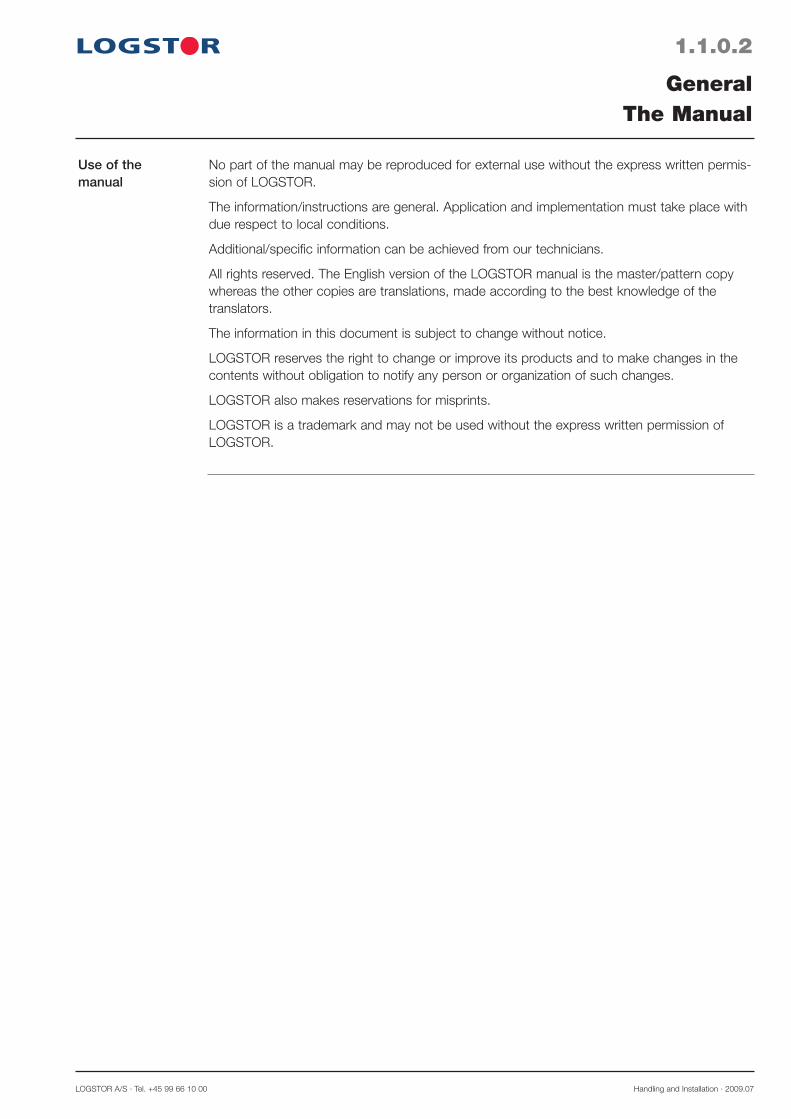
Dimension Max. stacking height, H (m) Outer casing Cushions of sand Sleepers
Stack the pipes so the maximum height is in accordance with the shown table.
FlexPipes in coils ; Hmax = 2 m
Stock pipes in such a way that they are not damaged.
Stack the pipes on a level surface of stone-less sand with cushions of sand as it appears from the illustration.
Instead of cushions of sand sleepers with a min. width of 100 mm may be used.
Place the pipes so the labels are at the same end in order to facilitate the wire connection, when installing pipes.
90-160 1.5 1.5 180-355 2.0 1.5 400-1100 3.0 2.0 1200-1400 3.0 Max. 2 layers
Store pallets with foam liquids indoors at 16-22°.Likewise store shrink materials, sealing strip and parts for the surveillance system indoors or under cover.All casing joints of plastic materials must be stored vertically, resting on one end in order to avoid ovalization.
The consignee makes material and personnel available for unloading, unless otherwise arranged.Do not throw or roll pipes and other components directly on to the ground.
max. 5 m min.400 mm
max
. H m

Handling and Installation · 2009.07 LOGSTOR A/S · Tel. +45 99 66 10 00
1.2.0.2
Handling, straight pipes
GeneralStorage and transport
100mm
Avoid damage to the outer PE-casing and the PUR-foam insulation.
Do not lift the pipes at only one spot and take care when using double straps in wet weather. They may slide together andunbalance the lift.
Only use lifting straps with a width of min. 100 mm.
Max. pressure on the outer casing< 300 kPa/ (0.3 N/mm2).
Only use chain or steel wire when lifting at the steel pipe ends.
Note! This handling may deform or dam-age the outer casing, if the strap is not long enough.
100 mmOnly use lifting straps with a width of min. 100 mm.
When using a truck protect the forks with casing pipe, rubber pads etc.
Handling, FlexPipes
LOGSTOR A/S · Tel. +45 99 66 10 00 Handling and Installation · 2009.07
1.3.0.1
GeneralExcavation, installation and backfilling of trench
<400 mmmin.
400mm
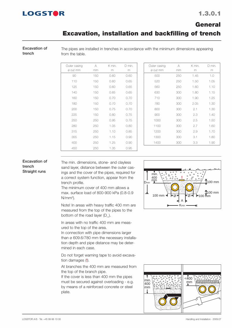
At branches the 400 mm are measured from the top of the branch pipe.If the cover is less than 400 mm the pipes must be secured against overloading - e.g. by means of a reinforced concrete or steel plate.
Excavation of trench
The pipes are installed in trenches in accordance with the minimum dimensions appearing from the table.
Outer casingø out mm
Amm
K min.m
D min.m
90 150 0.60 0.60
110 150 0.60 0.65
125 150 0.60 0.65
140 150 0.65 0.65
160 150 0.70 0.70
180 150 0.70 0.70
200 150 0.75 0.70
225 150 0.80 0.75
250 250 0.95 0.75
280 250 1.05 0.80
315 250 1.10 0.85
355 250 1.15 0.90
400 250 1.25 0.90
450 250 1.35 0.95
Outer casingø out mm
Amm
K min.m
D min.m
500 250 1.45 1.0
520 250 1.50 1.05
560 250 1.60 1.10
630 300 1.80 1.15
710 300 1.90 1.25
780 300 2.05 1.30
800 300 2.1 1.30
900 300 2.3 1.40
1000 300 2.5 1.50
1100 300 2.7 1.60
1200 300 2.9 1.70
1300 300 3.1 1.80
1400 300 3.3 1.90
Excavation of trenchStraight runs
The min. dimensions, stone- and clayless sand layer, distance between the outer cas-ings and the cover of the pipes, required for a correct system function, appear from the trench profile.The minimum cover of 400 mm allows a max. surface load of 800-900 kPa (0.8-0.9 N/mm2).
Note! In areas with heavy traffic 400 mm are measured from the top of the pipes to the bottom of the road layer (Dmin).
In areas with no traffic 400 mm are meas-ured to the top of the area.In connection with pipe dimensions larger than ø 609.6/780 mm the necessary installa-tion depth and pipe distance may be deter-mined in each case.
Do not forget warning tape to avoid excava-tion damages (!).
100 mm 100 mm
100 mm
100 mm
Kmin
Dminmm400min.
!
ØØ
A
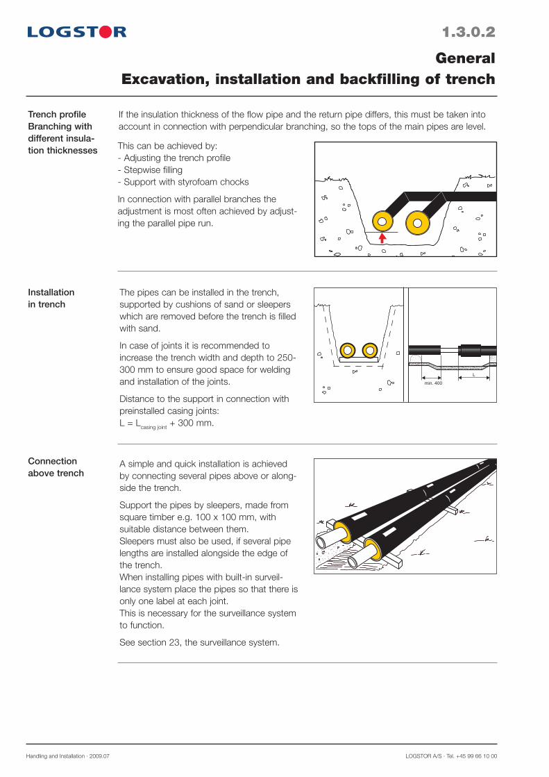
Trench profileBranching with different insula-tion thicknesses
If the insulation thickness of the flow pipe and the return pipe differs, this must be taken into account in connection with perpendicular branching, so the tops of the main pipes are level.
Handling and Installation · 2009.07 LOGSTOR A/S · Tel. +45 99 66 10 00
1.3.0.2
Installationin trench
Connection above trench
GeneralExcavation, installation and backfilling of trench
min. 400
L
.
.
.
..
..
...
..
.
.
...
.. .
...
.
. ...
. .
..
...
..
...... .
...
The pipes can be installed in the trench, supported by cushions of sand or sleepers which are removed before the trench is filled with sand.
In case of joints it is recommended to increase the trench width and depth to 250-300 mm to ensure good space for welding and installation of the joints.
Distance to the support in connection with preinstalled casing joints:L = Lcasing joint + 300 mm.
A simple and quick installation is achieved by connecting several pipes above or along-side the trench.
Support the pipes by sleepers, made from square timber e.g. 100 x 100 mm, withsuitable distance between them. Sleepers must also be used, if several pipe lengths are installed alongside the edge of the trench.When installing pipes with built-in surveil-lance system place the pipes so that there is only one label at each joint. This is necessary for the surveillance system to function.
See section 23, the surveillance system.
This can be achieved by:- Adjusting the trench profile- Stepwise filling- Support with styrofoam chocks
In connection with parallel branches the adjustment is most often achieved by adjust-ing the parallel pipe run.
LOGSTOR A/S · Tel. +45 99 66 10 00 Handling and Installation · 2009.07
1.3.0.3
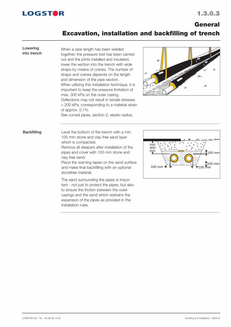
Backfilling
GeneralExcavation, installation and backfilling of trench
100 mm 100 mm
100 mm
100 mm
mm400min.
Level the bottom of the trench with a min. 100 mm stone and clay free sand layer which is compacted.Remove all sleepers after installation of the pipes and cover with 100 mm stone and clay free sand. Place the warning tapes on the sand surface and make final backfilling with an optional stonefree material.
The sand surrounding the pipes is impor-tant - not just to protect the pipes, but also to ensure the friction between the outer casings and the sand which restrains the expansion of the pipes as provided in the installation rules.
Loweringinto trench
..
......
... . ..
.. .. .
.
... .
... ..
.
. . .. . . .. ..
. ... .. .. ..
.. .. .. ....
..
. .
.
. ..
. .. .... .
... .. .. .. .....
.When a pipe length has been welded together, the pressure test has been carried out and the joints installed and insulated, lower the section into the trench with wide straps by means of cranes. The number of straps and cranes depends on the length and dimension of the pipe section.When utilizing this installation technique, it is important to keep the pressure limitation of max. 300 kPa on the outer casing. Deflections may not result in tensile stresses > 200 kPa, corresponding to a material strain of approx. 0.1%.See curved pipes, section 2, elastic radius.

Removing foamfrom possiblealarm wires
When cutting and adapting pipes with inte-gral copper wires for the surveillance system avoid to stress these wires during the remov-al of the foam insulation.Remove the foam around the wires and cut them.Then carefully pull the loosened foam insula-tion from the wire ends.
Handling and Installation · 2009.07 LOGSTOR A/S · Tel. +45 99 66 10 00
1.4.0.1
Cutting and adaption of pipes
GeneralCutting and adaption of pipes
22090˚ 90˚
440
When pipes are cut or adapted it is neces-sary to remove part of the outer casing and the PUR-foam insulation for a certain length from the steel pipe.It is essential that the bare steel pipe end is thoroughly cleaned and free from foamremnants.Also see the valid installation instructions for the casing joint in question.
Cutting the outer casing
Removal ofouter casing
440
Cut the outer casing around the entire cir-cumference with a saw - never an angle grinder, except for the cases, mentioned in the following.Beware of possible alarm wires.Hand saw and electric jig saw are preferable. Use electrical circular saw with caution.In cold periods/areas preheat the PE-outer casing, before cutting, with a soft gas flame to 20-30°C (lukewarm).Notice that the heat relatively slowly pen-etrates the plastic material; but do not super-heat, especially not on locations where plas-tic weldings are later carried out.Use a tent and a heating gun, if large wall thicknesses and diameters are to be pre-heated. Also see Winter measures, section 1.5.
Remove the outer casing by making a diag-onal cut. Do not damage the remaining outer casing, because it can cause a notch effect which might start cracks at casing pipe ends.
LOGSTOR A/S · Tel. +45 99 66 10 00 Handling and Installation · 2009.07
1.4.0.2
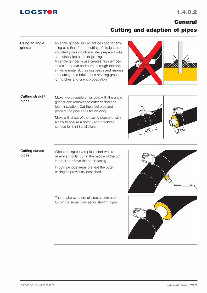
Using an angle grinder
Cutting straight pipes
Cutting curved pipes
GeneralCutting and adaption of pipes
An angle grinder should not be used for any-thing else than for the cutting of straight pre-insulated pipes which are later prepared with bare steel pipe ends for jointing.An angle grinder in use creates high temper-atures in the cut and burns through the poly-ethylene material, creating beads and making the cutting area brittle, thus creating ground for notches and crack propagation
Make two circumferential cuts with the angle grinder and remove the outer casing and foam insulation. Cut the steel pipe and prepare the pipe ends for welding.
Make a final cut of the casing pipe end with a saw to ensure a notch- and crackfree surface for joint installation.
When cutting curved pipes start with a relieving circular cut in the middle of the cut in order to relieve the outer casing.
In cold periods/areas preheat the outer casing as previously described.
Then make two normal circular cuts and follow the same rules as for straight pipes.
Handling and Installation · 2009.07 LOGSTOR A/S · Tel. +45 99 66 10 00
1.4.0.3
Removing foam
Welding
GeneralCutting and adaption of pipes
440 mm
440 mm
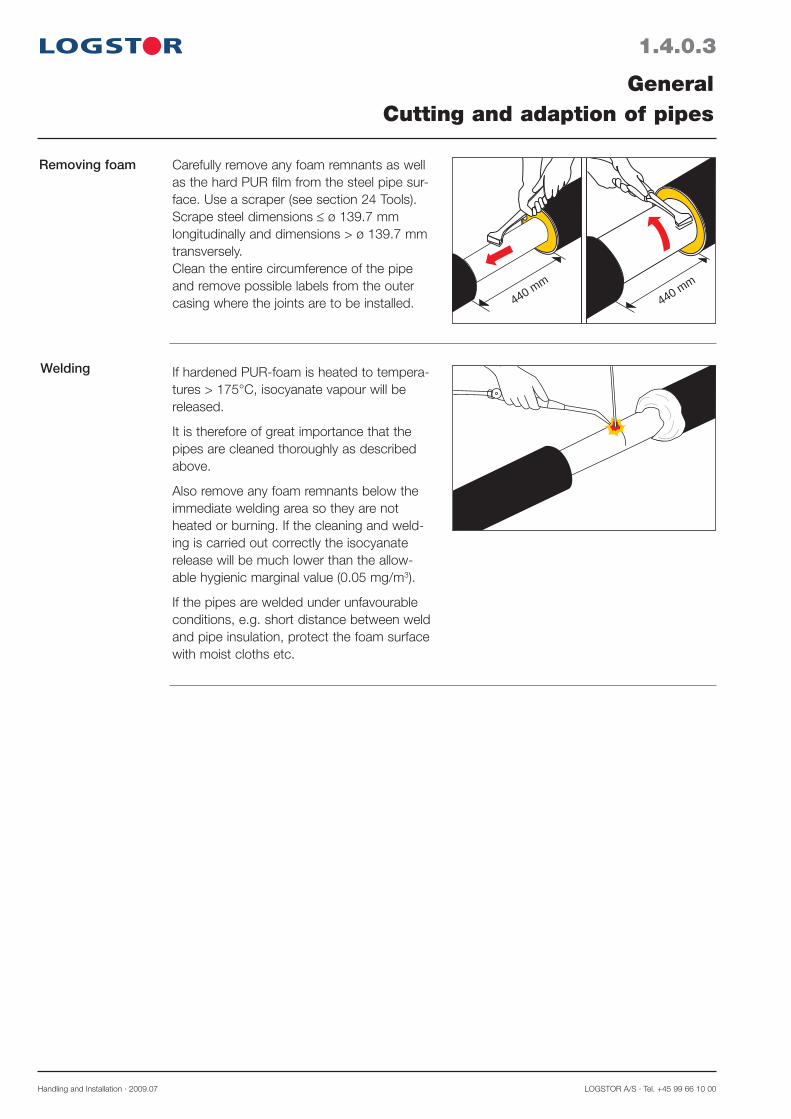
Carefully remove any foam remnants as well as the hard PUR film from the steel pipe sur-face. Use a scraper (see section 24 Tools).Scrape steel dimensions ø 139.7 mm longitudinally and dimensions > ø 139.7 mm transversely.Clean the entire circumference of the pipe and remove possible labels from the outer casing where the joints are to be installed.
If hardened PUR-foam is heated to tempera-tures > 175°C, isocyanate vapour will be released.
It is therefore of great importance that the pipes are cleaned thoroughly as described above.
Also remove any foam remnants below the immediate welding area so they are not heated or burning. If the cleaning and weld-ing is carried out correctly the isocyanate release will be much lower than the allow-able hygienic marginal value (0.05 mg/m3).
If the pipes are welded under unfavourable conditions, e.g. short distance between weld and pipe insulation, protect the foam surface with moist cloths etc.

LOGSTOR A/S · Tel. +45 99 66 10 00 Handling and Installation · 2009.07
1.5.0.1
Winter measures
Handling
Cutting and adaption
GeneralWinter measures
At outer casing temperatures lower than -10° C the measures, described below should be regarded, when
· handling· cutting and adapting· removing insulation from· bending
preinsulated pipes must be focused upon in addition to the other statements in the manual.
The reason:All plastic materials become more rigid/sensitive towards wrong treatment at low tempera-tures. During the foaming process inner stresses have been induced to the outer casing which are affected by handling and working.
Note! When working with pipes in cold periods/areas follow the given instructions, even though the sun is shining. A frozen pipe is not heated to summer conditions, just because the temperature suddenly rises.
The preheating rules at outdoor temperatures below +10°C apply to foaming and application of sealing strips/mastic etc.
Also see general preparation rules, section 5.1.
Do not expose the outer casing to extreme influences - e.g. impacts, shocks, large deflections and strong compressive forces - when handling it in cold periods/areas.
Prior to cutting preheat the outer casing with a soft gas flame to frostfree condition.
Notice that the heat relatively slowly pene-trates the plastic material, on the other hand do not superheat, especially not on locations where plastic weldings are later carried out.Use a tent and a heating gun, if large wall thicknesses and diameters are to bepreheated.
Especially at low temperatures sharp notches e.g. when making a diagonal cut must be avoided.
Always neutralize possible notches before installing a joint.
>0°C
Handling and Installation · 2009.07 LOGSTOR A/S · Tel. +45 99 66 10 00
1.5.0.2
Cutting curved pipes
Cutting for branch saddles
Bending on-site curved pipes
GeneralWinter measures
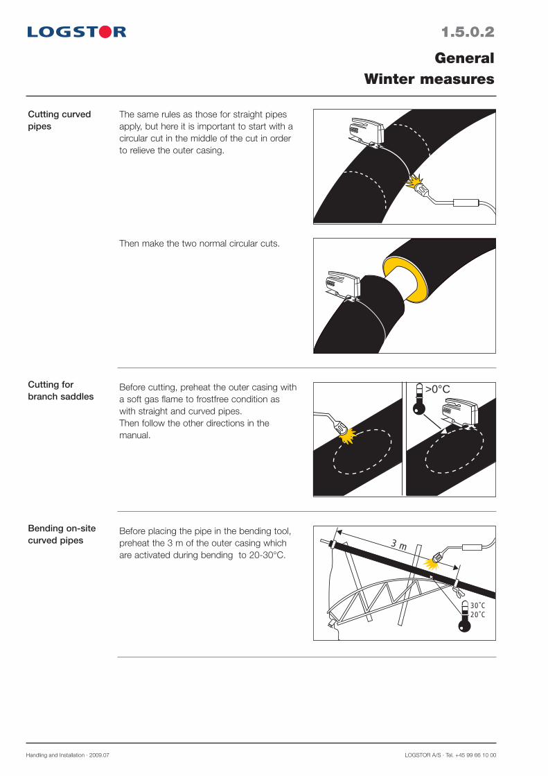
The same rules as those for straight pipes apply, but here it is important to start with a circular cut in the middle of the cut in order to relieve the outer casing.
Before cutting, preheat the outer casing with a soft gas flame to frostfree condition as with straight and curved pipes.Then follow the other directions in the manual.
Before placing the pipe in the bending tool, preheat the 3 m of the outer casing which are activated during bending to 20-30°C.
Then make the two normal circular cuts.
>0°C
30˚C20˚C
3 m

LOGSTOR A/S · Tel. +45 99 66 10 00 Handling and Installation · 2009.07
1.5.0.3
Bending FlexPipes
Storage and use of foam packs
Foamingpreparations
Sealing strip
GeneralWinter measures
When bending the outer casing, preheat the section which is influenced by the bending.The preheating rule also applies to tilted bores in the base or inlet pipes.Bend the pipe slowly and smoothly, not jerkily.Avoid to bend the utmost 25-30 cm of the pipe because of the bounce effect.Unrolling and straightening do not require preheating, only common caution.
Foam packs are stored in insulation boxes at 15-25°C.Under winter conditions this means: indoors in suitable store rooms.
Job-site temperature:If this temperature is less than +10°C, then preheat the joint parts with a soft gas flame to 20-30°C, just before filling in the foam liquid.
If hot water is circulating in the pipes, itsuffices that the joint parts have reached a temperature of approx. 20°C.
Should be stored at temperatures of 10-20°C to prevent it from becoming rigid and cold to work with. (The adhesiveness is reduced).At installation temperatures below 10° C the outer casing ends must be preheated, before installing sealing strip.Also preheat the flanges of steel fittings to achieve a good adhesiveness.
81132x1323.96
5
30°C20°C
30°C20°C
30˚C20˚C


LOGSTOR A/S · Tel. +45 99 66 10 00 Handling and Installation · 2012.04
2.0.0.1
Introduction
Contents
CurvesOverview
This sections contains rules for carrying out and handling curves on the site; both on-site and curved pipes.
Making curves on-site 2.1Installing curved pipes 2.2Utilizing elastic radius 2.3


LOGSTOR A/S · Tel. +45 99 66 10 00 Handling and Installation · 2012.04
Horizontal installation
Tools
Obtainable radii (m) with bending tools
Cover Steel pipe ø out. mm m 26.9 33.7 42.4 48.3 60.3 76.1 88.9
Bending tools in four different sizes are used.
26.9 4.9 8.2 18 39 33.7 *4.3 6.7 12 25 42.4 5.8 9.4 16 48.3 *5.4 8.5 13.3 60.3 7.5 11.0 76.1 *6.9 9.6 88.9 9.1
Steel pipe Tool No. ø out. mm 1 2 3 4
The table is based on the following minimum radii in m at the stated soil covers.(See also 2.3: Elastic radius).
The bold figures are the radii for which the tool in question is primarily constructed. The figures in the hatching indicate the radii for which tools are not required.
The figures with *) state the radii which may be made with the tool. but which require a larger installation depth than 0.4 m. See table in connection with horizontal installa-tion.
The pipes may also be established as elastic curves. See table section 2.3.
0.4 5.9 7.6 7.7 9.3 12.0 13.0 15.0 0.5 5.1 6.6 6.9 8.0 10.0 12.0 13.0 0.6 4.6 5.9 6.2 7.2 9.0 10.0 12.0 0.7 4.1 5.3 5.5 6.4 8.0 9.2 11.0 0.8 3.8 4.8 5.1 5.2 7.3 8.3 9.6
R
2.1.0.1
On-site made curves
CurvesMaking curves on-site
Preinsulated pipes in dimensions ø 26.9-88.9 mm can be bent to on-site made curves in con-nection with the installation. A condition is that the curves are installed horizontally and that a soil cover of min. 0.4 m is established.When on-site made curves are used to change level. special attention must be paid to soil cover. buoyancy etc. and consequently the min. radius is larger than the one in connection with corresponding horizontal installation.Contact LOGSTOR’s technicians for calculation of the required vertical radius.
Tool No. Radius m
1 2.9
2 3.8
3 5.1
4 6.5
Handling and Installation · 2012.04 LOGSTOR Fredericia A/S · Tel. +45 76 23 30 00
2.1.0.2
Bendinginstructions
CurvesMaking curves on-site
3 m
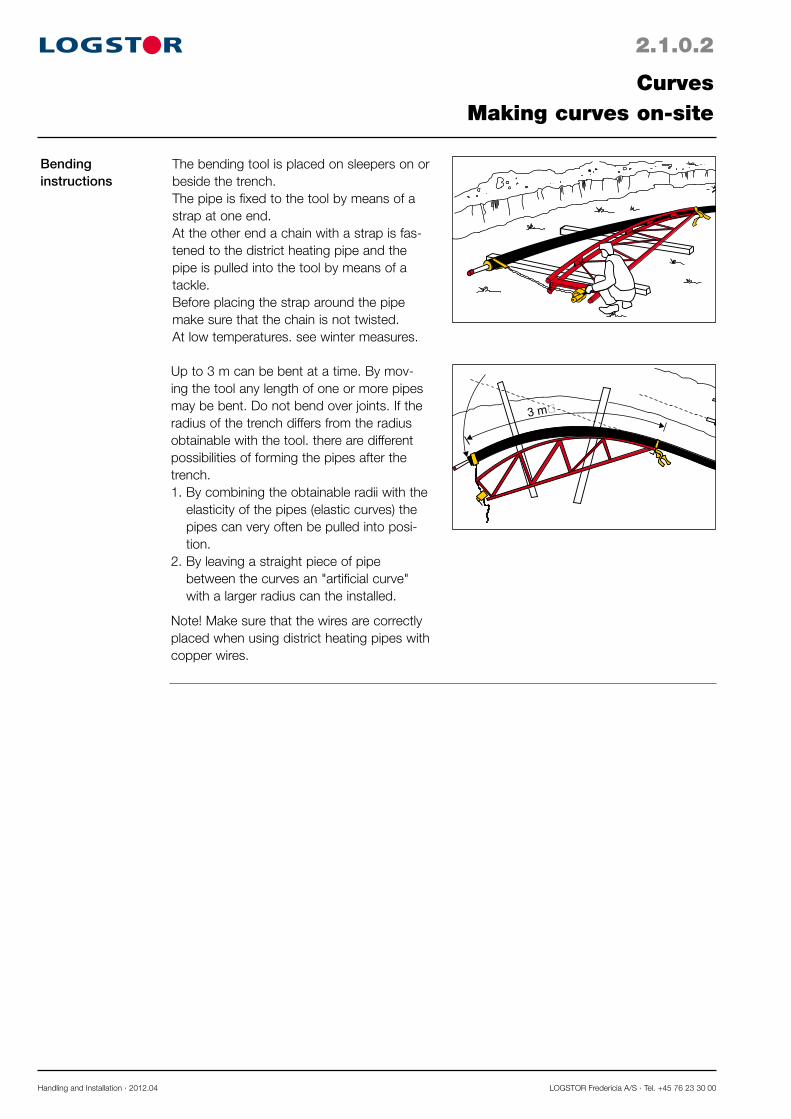
The bending tool is placed on sleepers on or beside the trench.The pipe is fixed to the tool by means of a strap at one end. At the other end a chain with a strap is fas-tened to the district heating pipe and the pipe is pulled into the tool by means of a tackle.Before placing the strap around the pipe make sure that the chain is not twisted.At low temperatures. see winter measures.
Up to 3 m can be bent at a time. By mov-ing the tool any length of one or more pipes may be bent. Do not bend over joints. If the radius of the trench differs from the radius obtainable with the tool. there are different possibilities of forming the pipes after the trench. 1. By combining the obtainable radii with the
elasticity of the pipes (elastic curves) the pipes can very often be pulled into posi-tion.
2. By leaving a straight piece of pipe between the curves an "artificial curve" with a larger radius can the installed.
Note! Make sure that the wires are correctly placed when using district heating pipes with copper wires.

LOGSTOR A/S · Tel. +45 99 66 10 00 Handling and Installation · 2012.04
2.2.0.1
Curved pipes
Installation instructions,Positioning of alarm wire
Information from the label of the curved pipe
CurvesInstalling curved pipes
Preinsulated pipes in dimensions ø 114.3-609.6 mm are delivered from our production plant bent to the project requirements.
When ordering state the required radius on the basis of the centre line of the trench and/or angular deviation each 12 m.
In some cases more curved pipes are necessary to obtain the required angle. This will appear from the pipe drawing.
Curved pipes are available in 12 or 16 m lengths and the angle and designing radius appear from the label on the curved pipe.
If the plant is made with a surveillance system it will appear from the label whether the pipe is bent · up· down· left · right
The direction is defined on the basis of the pipe position where tinned wires = alarm wires are always to the right and bare copper wires to the left.
This refers to the symbols of the surveillance diagram; full-drawn and dotted line respec-tively
From the label on the curved pipe the designing radius/angle as well as reference number and positioning according to the project drawing may appear.

Handling and Installation · 2012.04 LOGSTOR Fredericia A/S · Tel. +45 76 23 30 00
2.2.0.2
Setting out
CurvesInstalling curved pipes
Adjustment"Elastic curves"
Sp
p
A
A
t
pt
Ftp
F2
Note! When setting out the trench on site the tangent point (tp) of the curve must be marked. It is also important that the curved pipes start and end at the tangent points. The tangent point (tp) is measured from the point (sp). where the two centre lines of the trench intersect. Consequently. the points (tp) and (sp) as well as the distance (A) between these two points must always appear from the project drawing.
Curved pipes for flow and return are deliv-ered bent to the same angle. In order to make the pipes follow each other through the curve a displacement measure-ment in relation to the tangent point is calcu-lated.
The displacement measurement (F) is deter-mined as
D = outer casing diameter a = distance between the pipesv°a = angle of the curve in question
If the radius of the trench and that of the delivered curved pipes differ. an adjustment is obtained in accordance with the table of elastic radius/angle.
Steelpipe
ø out. mm
Elastic angle/radius
Angle Radius
12 m 16 m m
114.3 11 16 57
139.7 9 13 70
168.3 7 11 84
219.1 6 8 110
273 5 7 137
323.9 4 6 162
355.6 3.5 5 178
406.4 3 5 203
457 3 4 229
508 3 4 254
610 2 3 305
LOGSTOR A/S · Tel. +45 99 66 10 00 Handling and Installation · 2012.04
2.2.0.3
Example of adjustment
CurvesInstalling curved pipes
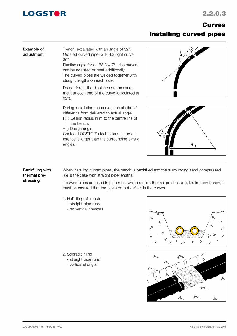
Trench. excavated with an angle of 32°.Ordered curved pipe: ø 168.3 right curve 36°Elastisc angle for ø 168.3 = 7° - the curves can be adjusted or bent additionally.The curved pipes are welded together with straight lengths on each side.
Do not forget the displacement measure-ment at each end of the curve (calculated at 32°).
During installation the curves absorb the 4° difference from delivered to actual angle.Rp : Design radius in m to the centre line of
the trench.v°p: Design angle.Contact LOGSTOR’s technicians. if the dif-ference is larger than the surrounding elastic angles.
V˚p
Rp
Backfilling with thermal pre-stressing
When installing curved pipes, the trench is backfilled and the surrounding sand compressed like is the case with straight pipe lengths.
If curved pipes are used in pipe runs, which require thermal prestressing, i.e. in open trench, it must be ensured that the pipes do not deflect in the curves.
1. Half-filling of trench - straight pipe runs - no vertical changes
2. Sporadic filling - straight pipe runs - vertical changes

Handling and Installation · 2012.04 LOGSTOR Fredericia A/S · Tel. +45 76 23 30 00
Backfilling with thermal pre-stressing, continued
ab
c
3. Control in the curvea. Lathingb. Styrofoam blocksc. Sand bags
2.2.0.4
CurvesInstalling curved pipes

LOGSTOR A/S · Tel. +45 99 66 10 00 Handling and Installation · 2012.04
2.3.0.1
Application
CurvesUtilizing elastic radius
R
p
Pipes can be installed as elastic curves in road curves with large radii of curvature in accordance with the values in the table (max. bend stress = 210 N/mm2).
Rmin allowable is 500 x the steel pipe outer diam-eter.
Weld the pipes together into one straight section and then install them in a curved trench.
Note! The natural elasticity of the pipes may also be used for small adjustments in con-nection with other pipe systems e.g. curved pipes.
Steelpipe
ø out.mm
Min.allowable
radiusR m
Directionalchange v°
each12 m/16 m
Result. archeight. p
approx mm length12 m/16 m
26.9 13 51 1320
33.7 17 41 1060
42.4 21 32 840
48.3 24 28 740
60.3 30 23 600
76.1 38 18 470
88.9 44 15 400
114.3 57 12/16 310/560
139.7 70 10/13 260/460
168.3 84 8/11 210/380
219.1 110 6/8 160/290
273 137 5/7 130/230
323.9 162 4/6 110/200
355.6 178 4/5 100/180
406.4 203 3/5 90/160
457 229 3/4 80/140
508 254 3/4 70/130
610 305 2/3 60/110


LOGSTOR A/S · Tel. +45 99 66 10 00 Handling and Installation · 2009.10
3.0.0.1
Introduction
Contents
E-CompsOverview
This section contains instructions and conditions for installing expansion components after installation method III, the E-system.
Installing E-Comps, general 3.1Installing E-Comps in the E 70-system 3.2

LOGSTOR A/S · Tel. +45 99 66 10 00 Handling and Installation · 2009.10
Requirements to the joint area
Tools
Space conditions, see section 1.2 excavation, installation.Preparing joint installation, see section 5.1.
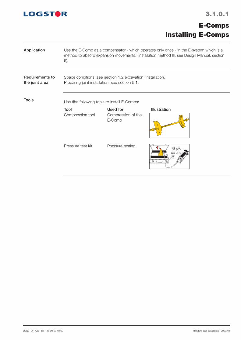
Pressure test kit Pressure testing
Use tihe following tools to install E-Comps:
Tool Used for IllustrationCompression tool Compression of the
E-Comp
3.1.0.1
Application
E-CompsInstalling E-Comps
Use the E-Comp as a compensator - which operates only once - in the E-system which is a method to absorb expansion movements. (Installation method III, see Design Manual, section 6).

Handling and Installation · 2009.10 LOGSTOR Fredericia A/S · Tel. +45 76 23 30 00
e-measurement
e
e
ø42,4 - 139,7mm
E EE
R
e
e
ø168,3 - 610mm
The e-measurement is so to speak the gap, required for the E-Comp to be able to absorb the coming expansion.
To determine the e-measurement the follow-ing factors must be known:1. td which is the normal operating tempera-
ture of the system
2. tm which is the ambient temperature at the time of installation of the E-Comp.
3. R is the length in m of the pipe section for the E-Comp to serve
These factors are included in the formula:
e mm = (td - tm) x R x 0.0062
where 0.0062 is a constant allowing for i.a. friction, allowable stresses, safety factors etc.
Example of determination of the e-measure-ment:Operating temperature: 110°CInstallation temperature: 20°CPipe length R = 144 m
e = (110 - 20) x 144 x 0.0062 = 80 mm
3.1.0.2
Determining the e-measurement for the standard E-system
E-CompsInstalling E-Comps
The E-Comp is a component which operates only once when it absorbs a movement cor-responding to the expansion of a certain pipe length, R, the first time hot water runs through the pipes.

LOGSTOR A/S · Tel. +45 99 66 10 00 Handling and Installation · 2009.10
Adjusting the E-Comp
Example of E-Comp label
e
e
td-tm (°C)
R (m)
140
120
100
80
60
40
20
0 20 40 60 80 100 120
160
180
140
120
100
80
60
40
20
e-max
Part No. 0006 0219 032 000 ø219,1
(mm)
e
E1
E2R1
R2
R e
No
90
144
144 80
2
(144)
a
b
P maxbar
0,5-9 3x45 3
15 3x45 4
24 3x55 5
37,5 3x80 5
L minmm
P maxbar
LOGSTOR pat.
0,5-9 20 5 3x45 3 110
15 20 5 3x55 3 110
24 20 5 3x85 3 110
37,5 20 5 3x125 3 110
B minmm
tmm
L minmm
a minmm
Rmm
a minmm
84218
t
a
RB
La
c
d
e
Adjust the E-Comp by means of the com-pression tool.Mark the e-measurement from the stop marking and compress the joint.The distance between the two pipe ends in the E-Comp will then be exactly the same.
a. Determination of e-measurement on the basis of design conditions
b. Reference to project drawingc. Presettingd. Fixing by means of tack weldinge. Fixing by means of fixing bars
3.1.0.3
E-CompsInstalling E-Comps
Fix the adjusted measurement by means of tack welds or fixing bars.This gives the joint mechanical strength during the installation and the pressure test of the pipeline.The number of tack welds or fixing bars and the length of the welds appear from the label on the E-Comp, see example below. The weld must comply with the a-measure-ment, stated on the label.Due to the later removal of the tacks fixing bars are recommended, as possible burrs from the welding may otherwise hamper the compression.
Fixing the E-Comp
Handling and Installation · 2009.10 LOGSTOR Fredericia A/S · Tel. +45 76 23 30 00
3.1.0.4
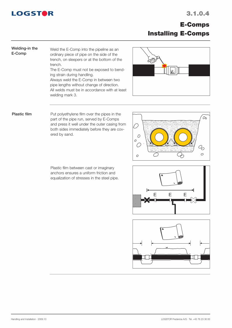
Plastic film
E-CompsInstalling E-Comps
E E E
yyyyyyyyyyyyyyyyyyyyyyyy
yyyyyyyyyyyy
Put polyethylene film over the pipes in the part of the pipe run, served by E-Comps and press it well under the outer casing from both sides immediately before they are cov-ered by sand.
Plastic film between cast or imaginary anchors ensures a uniform friction and equalization of stresses in the steel pipe.
Welding-in the E-Comp
Weld the E-Comp into the pipeline as an ordinary piece of pipe on the side of the trench, on sleepers or at the bottom of the trench.The E-Comp must not be exposed to bend-ing strain during handling.Always weld the E-Comp in between two pipe lengths without change of direction.All welds must be in accordance with at least welding mark 3.

LOGSTOR A/S · Tel. +45 99 66 10 00 Handling and Installation · 2009.10
3.1.0.5
E-CompsInstalling E-Comps
Film width The width of the film which is rolled out along the pipes varies dependent on the outer cas-ing dimension.
Outer casingø out. mm
Widthmm
110-160 500
200-315 1000
355-450 1500
500-630 2000
710-780 2500
Preparations for welding
a
Remove the tack welds or the fixing bars on the E-Comps with an angle grinder. All welding burrs must be removed to ensure correct compression of the E-Comp when the pipes are heated.This makes the E-Comps move towards each other until they meet.
Note! For practical reasons the pre-adjust-ment of the flow and return joints is the same, i.e. a sufficiently high circulation must be established to ensure the same tempera-ture in the entire system.
Now weld the compressed E-Comp by gas or arc welding.
Pressure testing Remove the iron plug from the E-Comp.
Make the pressure test by means of the connecting stub included in the pressure testing equipment.
Screw in the iron plug again and seal it with a weld.
The E-system is now established and water-proof. Future temperature variations in the system will be converted into allowable ten-sile or compressive stresses.
Steel pipe, ø out. mm a-measurement, mm 42.4-88.9 3 114.3-139.7 4 168.3-219.1 5 273-323.9 6 355.6 8 406.4-559 9 610 10

Handling and Installation · 2009.10 LOGSTOR Fredericia A/S · Tel. +45 76 23 30 00
3.1.0.6
E-CompsInstalling E-Comps
Insulation Insulate the joint as usual.
In general use longer casing joints, when insulating E-Comp joints.

LOGSTOR A/S · Tel. +45 99 66 10 00 Handling and Installation · 2009.10
3.2.0.1
E-CompsInstalling E-Comps in E 70-system
Application
Determining e-measurement for the E 70-system
e-measurement
The E 70-system is used when a preheating temperature of only 70°C (ex. summer operation) can be reached.
The E-Comp is a component which operates only once when it absorbs a movement cor-responding to the expansion of a certain pipe length, R, the first time hot water runs through the pipes.
e
e
ø42,4 - 139,7mm
E EE
R
e
e
ø168,3 - 610mm
The e-measurement is so to speak the gap, required for the E-Comp to be able to absorb the coming expansion.
R is the pipe length in m of the pipe section, served by the E-Comp.
This factor is included in the following for-mula:e (mm) = 0.43 x R (m)
Example of determination of the e-measure-ment:Pipe length R: 132 me = 0.43 x 132 = 56 mm.
Remaining installation
The remaining installation steps in the E 70-system are the same as those for standard E-Comps. See previous pages.


LOGSTOR A/S · Tel. +45 99 66 10 00 Handling and Installation · 2009.10
4.0.0.1
Introduction
Contents
Expansion and anchorageOverview
This section describes the conditions which must be present/fulfilled when preinsulated pipe systems require expansion possibilities or anchorage.
- Establishing expansion zones with sand 4.1- Establishing expansion zones with foam pads 4.2- Installing prefabricated anchors 4.3

LOGSTOR A/S · Tel. +45 99 66 10 00 Handling and Installation · 2009.10
4.1.0.1
Application
Sand pads
Expansion and AnchorageEstablishing expansion zones with sand
Max L60
2
60/2L
A1A
0,1-0,2
N/mm2
K+
10 cm
10 cm
10 cm E 10 cm
K
Pa
Pmax.
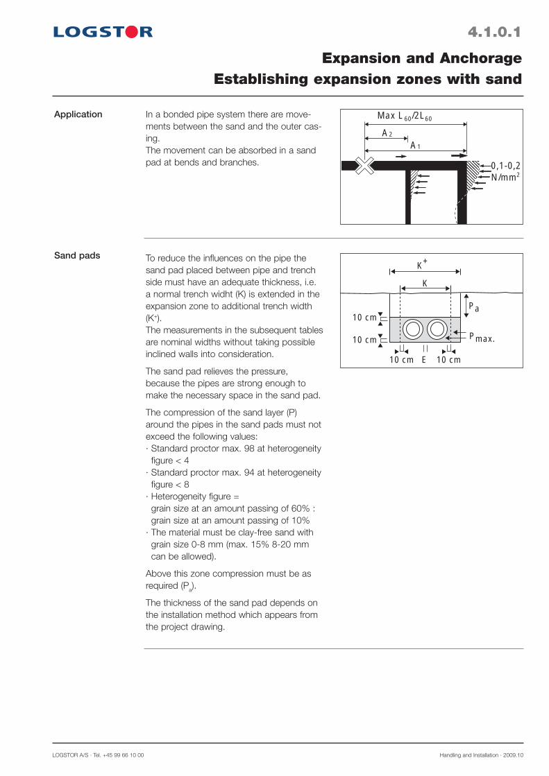
In a bonded pipe system there are move-ments between the sand and the outer cas-ing.The movement can be absorbed in a sand pad at bends and branches.
To reduce the influences on the pipe the sand pad placed between pipe and trench side must have an adequate thickness, i.e. a normal trench widht (K) is extended in the expansion zone to additional trench width (K+).The measurements in the subsequent tables are nominal widths without taking possible inclined walls into consideration.
The sand pad relieves the pressure, because the pipes are strong enough to make the necessary space in the sand pad.
The compression of the sand layer (P) around the pipes in the sand pads must not exceed the following values:· Standard proctor max. 98 at heterogeneity
figure < 4· Standard proctor max. 94 at heterogeneity
figure < 8· Heterogeneity figure =
grain size at an amount passing of 60% : grain size at an amount passing of 10%
· The material must be clay-free sand with grain size 0-8 mm (max. 15% 8-20 mm can be allowed).
Above this zone compression must be as required (Pa).
The thickness of the sand pad depends on the installation method which appears from the project drawing.
Handling and Installation · 2009.10 LOGSTOR A/S · Tel. +45 99 66 10 00
4.1.0.2
Sand pads for installation method I
Branches
Expansion and anchorageEstablishing expansion zones with sand
E
C
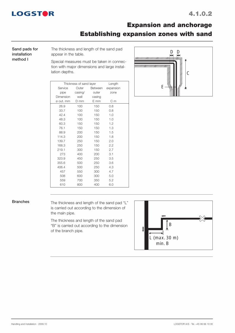
D DThe thickness and length of the sand pad appear in the table.
Special measures must be taken in connec-tion with major dimensions and large instal-lation depths.
B
L (max. 30 m) min. B
Thickness of sand layer Length Service Outer Between expansion pipe casing/ outer zone Dimension wall casing ø out. mm D mm E mm C m
26.9 100 150 0.8 33.7 100 150 0.8 42.4 100 150 1.0 48.3 100 150 1.0 60.3 150 150 1.2 76.1 150 150 1.3 88.9 200 150 1.5 114.3 200 150 1.8 139.7 250 150 2.0 168.3 250 150 2.2 219.1 300 150 2.7 273 400 200 3.1 323.9 450 250 3.5 355.6 500 250 3.6 406.4 500 250 4.3 457 550 300 4.7 508 600 300 5.0 559 700 350 5.2 610 800 400 6.0
The thickness and length of the sand pad “L” is carried out according to the dimension of the main pipe.
The thickness and length of the sand pad “B” is carried out according to the dimension of the branch pipe.
LOGSTOR A/S · Tel. +45 99 66 10 00 Handling and Installation · 2009.10
4.1.0.3
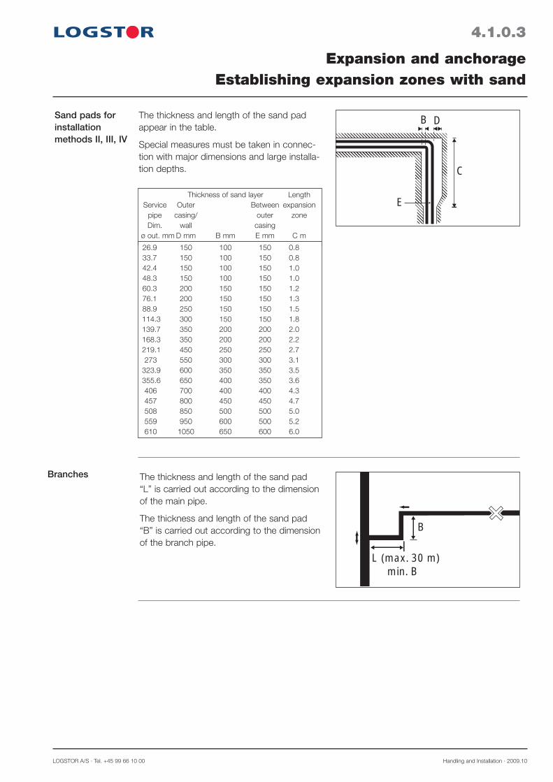
Sand pads for installation methods II, III, IV
Branches
Expansion and anchorageEstablishing expansion zones with sand
E
C
B DThe thickness and length of the sand pad appear in the table.
Special measures must be taken in connec-tion with major dimensions and large installa-tion depths.
B
L (max. 30 m) min. B
Thickness of sand layer Length Service Outer Between expansion pipe casing/ outer zone Dim. wall casing ø out. mm D mm B mm E mm C m
26.9 150 100 150 0.8 33.7 150 100 150 0.8 42.4 150 100 150 1.0 48.3 150 100 150 1.0 60.3 200 150 150 1.2 76.1 200 150 150 1.3 88.9 250 150 150 1.5 114.3 300 150 150 1.8 139.7 350 200 200 2.0 168.3 350 200 200 2.2 219.1 450 250 250 2.7 273 550 300 300 3.1 323.9 600 350 350 3.5 355.6 650 400 350 3.6 406 700 400 400 4.3 457 800 450 450 4.7 508 850 500 500 5.0 559 950 600 500 5.2 610 1050 650 600 6.0
The thickness and length of the sand pad “L” is carried out according to the dimension of the main pipe.
The thickness and length of the sand pad “B” is carried out according to the dimension of the branch pipe.

Handling and Installation · 2009.10 LOGSTOR A/S · Tel. +45 99 66 10 00
4.2.0.1
Application
Square measure of foam pads
Installing foam pads
Expansion and anchorageEstablishing expansion zones with foam pads
yyyyyyyyyyyyyyyyyyyyyyyyyyyyyyyyyyyyyyyyyyIn a number of cases the use of foam pads
has been replaced by sand pads. However, the foam pad can be used to absorb expansion movements when the first movement does not exceed the following intervals:
10 < · ΔL 35 mm, 1 layer35 < · ΔL 70 mm, 2 layers70 < · ΔL 105 mm, 3 layers
Install the pads on one or both sides of the outer casing in accordance with the project drawing.
In case of minor dimensions filament tape may be used to secure the pads.
For major dimensions and several layers it is recommended to wrap the pads in geotex-tile etc.
This prevents sand from entering between the foam pad and the outer casing, when backfilling the trench.
The foam pads are available in one size which is adjusted to the actual casing diameter.
Actual foam pad measure
The casing diameter determines the height of the foam pad, which again determines the number of foam pads.
D
LOGSTOR A/S · Tel. +45 99 66 10 00 Handling and Installation · 2009.10
4.2.0.2
The trench
Position and number of foam pads
Expansion and anchorageEstablishing expansion zones with foam pads
E
C
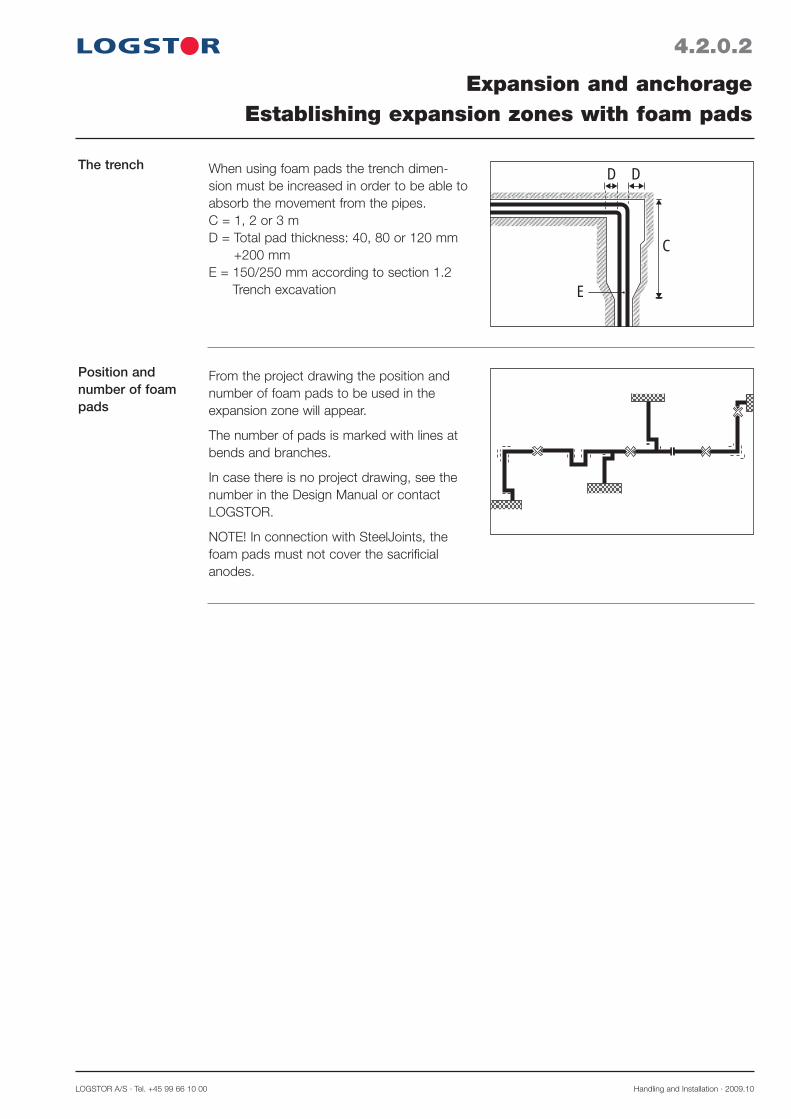
D DWhen using foam pads the trench dimen-sion must be increased in order to be able to absorb the movement from the pipes.C = 1, 2 or 3 mD = Total pad thickness: 40, 80 or 120 mm
+200 mmE = 150/250 mm according to section 1.2
Trench excavation
From the project drawing the position and number of foam pads to be used in the expansion zone will appear.
The number of pads is marked with lines at bends and branches.
In case there is no project drawing, see the number in the Design Manual or contact LOGSTOR.
NOTE! In connection with SteelJoints, the foam pads must not cover the sacrificial anodes.

Handling and Installation · 2009.10 LOGSTOR A/S · Tel. +45 99 66 10 00
4.3.0.1
Application
Prefabricated anchor, measure
Expansion and anchorageInstalling prefabricated anchor
Prefabricated anchors are installed in order to fix the pipeline for absorption of the expan-sion movements occurring in connection with pressure and temperature influences in the pipe system, if the design so requires. 220 mm
A
L/2
L
26,9 90 2000 140 110 2000 160 125 2000 165 33,7 90 2000 140 110 2000 160 125 2000 165 42,4 110 2000 170 125 2000 200 140 2000 200 48,3 110 2000 170 125 2000 200 140 2000 200 60,3 125 2000 200 140 2000 220 160 2000 220 76,1 140 2000 220 160 2000 235 180 2000 250 88,9 160 2000 235 180 2000 260 200 2000 300 114,3 200 2000 300 225 2000 320 250 2000 340 139,7 225 2000 320 250 2000 370 280 2000 370 168,3 250 2000 370 280 2000 400 315 2000 450 219,1 315 2000 450 355 2000 510 400 2500 525 273 400 2500 550 450 2500 600 500 2500 630 323,9 450 2500 600 500 2500 650 520 2500 670 355,6 500 2500 650 520 2500 700 560 2500 710 406,4 520 2500 700 560 2500 740 630 3000 800 457 560 2500 740 630 3000 800 710 3000 880 508 630 3000 800 710 3000 880 780 3000 950 610 780 3000 990 - - - - - -
Steel Series 1 Series 2 Series 3pipe Casing L A Casing L A Casing L Aout ø mm ø mm mm mm out. ø mm out. ø mm
LOGSTOR A/S · Tel. +45 99 66 10 00 Handling and Installation · 2009.10
4.3.0.2
Installation
Concrete anchor block
Expansion and anchorageInstalling prefabricated anchor
B
A
CB
A
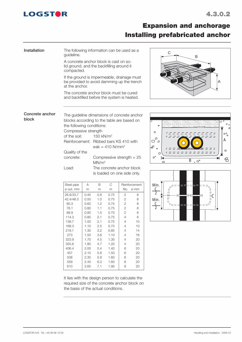
The guideline dimensions of concrete anchor blocks according to the table are based on the following conditions:Compressive strengthof the soil: 150 kN/m2
Reinforcement: Ribbed bars KS 410 with ak = 410 N/mm2
Quality of the concrete: Compressive strength = 25 MN/m2
Load: The concrete anchor block is loaded on one side only.
The following information can be used as a guideline.
A concrete anchor block is cast on so-lid ground, and the backfi lling around it compacted.
If the ground is impermeable, drainage must be provided to avoid damming up the trench at the anchor.
The concrete anchor block must be cured and backfi lled before the system is heated.
Min.C2
CMin.
C2
It lies with the design person to calculate the required size of the concrete anchor block on the basis of the actual conditions.
26.9/33.7 0.45 0.8 0.75 2 8 42.4/48.3 0.50 1.0 0.75 2 8 60.3 0.60 1.2 0.75 2 8 76.1 0.80 1.1 0.75 2 8 88.9 0.80 1.5 0.75 2 8 114.3 0.80 2.1 0.75 4 8 139.7 1.00 2.1 0.75 4 10 168.3 1.10 2.5 0.75 4 10 219.1 1.30 3.2 0.85 4 14 273 1.50 3.8 1.10 4 16 323.9 1.70 4.5 1.30 4 20 355.6 1.80 4.7 1.20 4 20 406.4 2.00 5.4 1.40 6 20 457 2.10 5.8 1.50 6 20 508 2.30 5.9 1.60 6 20 559 2.40 6.3 1.60 8 20 610 2.60 7.1 1.90 8 20
Steel pipe A B C Reinforcement ø out. mm m m m No. ø mm
Handling and Installation · 2009.10 LOGSTOR A/S · Tel. +45 99 66 10 00
4.3.0.3
Room for joint installation
Expansion and anchorageInstalling prefabricated anchor
min300
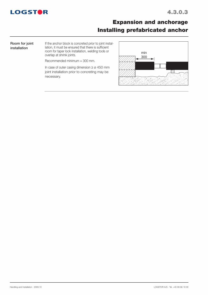
If the anchor block is concreted prior to joint instal-lation, it must be ensured that there is suffi cient room for taper lock installation, welding tools or overlap at shrink joints.
Recommended minimum = 300 mm.
In case of outer casing dimension ≥ ø 450 mm joint installation prior to concreting may be necessary.

LOGSTOR A/S · Tel. +45 99 66 10 00 Handling and Installation · 2008.10
5.0.0.1
Introduction
Contents
Installing casing joints, bends and branchesOverview
This section contains a description of the essential measures to take in connection with each joint installation.Specific measures for the different joint types are described under the installation instructions for the joint type.
Preparations for joint installation 5.1Installing straight joints 5.2Installing bends 5.3Installing branches 5.4


LOGSTOR A/S · Tel. +45 99 66 10 00 Handling and Installation · 2008.10
5.1.0.1
Preparations for joint installation
Room for instal-lation
Clean surfaces
Moist joint areas
Wet foam
Installing casing joints, bends and branchesPreparations for joint installation
After the pipes have been welded together a number of conditions must be fulfilled in order to ensure a correct installation of the joint.
. .
.. .... .
. . ... . . . .
. .....
...
.... ..
... .
.. . .
.... . . ..
..
.
.. .
..
..
.
...
. ....
. . ..... ..
... ... .
....
....
L
1. Support/excavate the pipes
2. Place sleepers min. 400 mm from the outer casing end or excavate to a corre-sponding extent.In connection with preinstalled casing joints:L = Lcasing joint + 300 mmSufficient room is necessary to make a correct and proper installation.See 1.2 regarding trench dimensions.
3. Wipe the joint area and all surfaces clean. Make sure they are both clean and dry.
Grind around the outer casing from both ends and inwards, using emery cloth, grain size 60, until the surface becomes mat.
To the EW and the band joint special proce-dures apply.
Clean and dry surfaces are a conditon of good sealing and adhesion of the joint installation.
4. Cover the joint area in moist and rainy weather.
5. Wipe the pipe ends dry and remove moist with a soft propane gas flame.
At temperatures below 10°C preheat the outer casing, before applying the sealing strip/adhesive material. See section 1.4 Winter measures.
6. Remove any wet PUR-foam from the pipe ends with a knife, e.g. if the pipe ends have been flooded.

Handling and Installation · 2008.10 LOGSTOR A/S · Tel. +45 99 66 10 00
Joint packaging 7. Keep the joints in their original packaging, until they are to beinstalled.All casing joints of plastic materials must be stored resting on one end in order to avoid deformation.Keep the joints indoors, if possible.The packaging ensures that the joints are clean and dry. Wipe possible condensed mois-ture off and/or remove it with a soft propane gas flame. The surface must be 35°C, luke-warm, in order to obtain the required effect.
5.1.0.2
Installing casing joints, bends and branchesPreparations for joint installation
The 5 Golden Rules
1. Preparation:All materials must be at hand and in the original packing, when the installation work starts.
2. Cleaning:All surfaces must be cleaned.
3. Activation:All plastic surfaces (outer casings) must be activated by means of grinding and a gas flame in order to remove the plastic oxides.
4. Installation:All parts of the joint must be installed in one work routine without interruptions. Foaming must take place the same day as the casing joint installation.
5. Inspection:Leakage test must be carried out before foaming. Checkpoints from the installation instruc-tions must be followed.
LOGSTOR A/S · Tel. +45 99 66 10 00 Handling and Installation · 2018.01
Introduction This section contains instructions for the installation of straight joints.
Contents Weld joints: - BandJoints 5.2.1 - PlateJoints 5.2.2 - EWJoints 5.2.3
Crosslinked PE shrink joints: - SXJoints 5.2.4 - SX-WPJoints 5.2.5 - BXJoints 5.2.6
PE shrink joints: - B2SJoints 5.2.7 - BSJoints 5.2.8
Repair joints: - C2L 5.2.9
5.2.0.1
Installing straight jointsOverview


LOGSTOR A/S · Tel. +45 99 66 10 00 Handling and Installation · 2018.01
5.2.1.1
Application
Installation equipment
Control of the welding process
Fitters
Installing straight jointsBandJoints
The installation must be carried out by certified fitters who have been specially educated and trained at LOGSTOR. An education and training which are kept up by follow-up courses at least every second year.
The BandJoint is an open weld joint which is installed after welding the service pipe togeth-er. It is used to insulate joints in dimensions ø 90-710 mm.The joint is made of the same material as the outer casing. Join it by means of fusion welding, by which the joint and pipe melt together in a computer controlled process.
Use a trailer containing generator, compres-sor, WeldMaster, straps and all necesssary tools for the installation work.
Carry out the welding process with LOGSTOR WeldMaster, which is a computer controlled welding machine which automati-cally controls the welding and checks that the welding temperature and the pressure between the welding surfaces are correct.
Installation instructions
The certified fitters must use the authorized installation equipment and follow the instructions in the Weld Joint Manual, which can be ordered from LOGSTOR.
WeldMaster

Handling and Installation · 2018.01 LOGSTOR A/S · Tel. +45 99 66 10 00
5.2.2.1
Application
Installation equip-ment
Control of the welding process
Fitters
Installing straight jointsPlateJoints
The installation must be carried out by certified fitters who have been specially educated and trained at LOGSTOR. An education and training which are kept up by follow-up courses at least every second year.
The PlateJoint is an open weld joint, installed after welding the service pipe together. It is used to connect pipes in casing dimensions from ø 780 mm up to and including ø 1400 mm.
It is made of a PE sheet.
It is joined by means of fusion welding, by which the joint and pipe melt together in a computer controlled welding process.
Use a trailer containing generator, compres-sor, WeldMaster, straps and all necesssary tools for the installation work.
Carry out the welding process with LOGSTOR WeldMaster, which is a computer controlled welding machine which automati-cally controls the welding and monitors the welding temperature.
WeldMaster
Installation instructions
The certified fitters must use the authorized installation equipment and follow the instructions in the Weld Joint Manual which can be ordered from LOGSTOR.

LOGSTOR A/S · Tel. +45 99 66 10 00 Handling and Installation · 2018.01
5.2.3.1
Installing straight jointsEWJoints
Application The EWJoint is a closed casing joint which is installed prior to welding the service pipe together. It is used to join pipes in outer cas-ing dimensions ø 90 mm to ø 1400 mm.
It is joined by shrinkage over hot wires, after which the sleeve and pipe melt together in a computer controlled welding process.
Installation equipment
Control of the welding process
Use a trailer containing generator, compres-sor, WeldMaster, straps and all necesssary tools for the installation work.
Carry out the welding process with LOGSTOR WeldMaster, which is a computer controlled welding machine which automati-cally controls the welding and monitors the welding temperature.
WeldMaster
Installation instructions
The certified fitters must use the authorized installation equipment and follow the instructions in the Weld Joint Manual which can be ordered from LOGSTOR.
Fitters The installation must be carried out by certified fitters who have been specially educated and trained at LOGSTOR. An education and training which are kept up by follow-up courses at least every second year.

Handling and Installation · 2018.01 LOGSTOR A/S · Tel. +45 99 66 10 00
Tools
5.2.4.1
Installing straight jointsSXJoints
Application The SXJoint is a closed shrink joint which is installted prior to welding the service pipe together. It is used for joints on pipes with outer casing dimensions ø 90-450 mm.
The two foam holes are sealed with expan-sion and wedge plugs as well as patches.
General guidelines for trench and casing joint installation, see section 5.1 ”Preparations for joint installation”.
Connecting alarm wires, see sections 23.3 and 23.4.
Foam pack: – Size, see Product Catalogue section 15 – Further information, see Handling &
Installation section 7
Preinstallation of casing joint
1. Place the shrink sleeve with packing on one of the pipes before the service pipes are joined.
The following tools must be used when installing SXJoints:
4
5 6
1 2 3
7 8
65°
9
1. Alcohol, min. 93%
2. Emery cloth, grain size 36-60
3. Gloves
4. Gas burner: ø 50 mm: Minor dimensions ø 60 mm: Major dimensions
5. Leakage test equipment
6. Hammer
7. Patch spoon
8. Patch press
9. Temperature measuring device
LOGSTOR A/S · Tel. +45 99 66 10 00 Handling and Installation · 2018.01
5.2.4.2
Installing straight jointsSXJoints
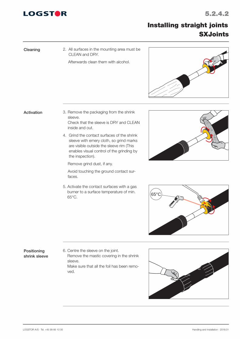
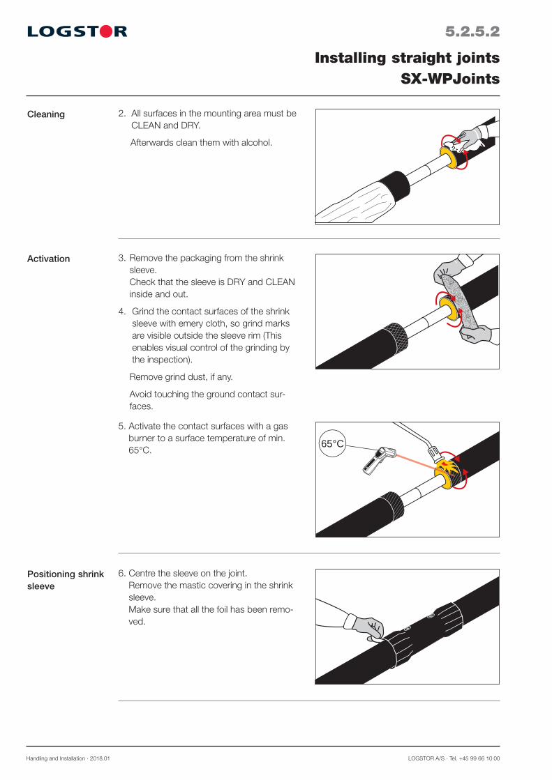
6. Centre the sleeve on the joint. Remove the mastic covering in the shrink sleeve. Make sure that all the foil has been remo-ved.
65°
65°C
5. Activate the contact surfaces with a gas burner to a surface temperature of min. 65°C.
2. All surfaces in the mounting area must be CLEAN and DRY.
Afterwards clean them with alcohol.
3. Remove the packaging from the shrink sleeve. Check that the sleeve is DRY and CLEAN inside and out.
4. Grind the contact surfaces of the shrink sleeve with emery cloth, so grind marks are visible outside the sleeve rim (This enables visual control of the grinding by the inspection).
Remove grind dust, if any.
Avoid touching the ground contact sur-faces.
Cleaning
Activation
Positioning shrink sleeve
Handling and Installation · 2018.01 LOGSTOR A/S · Tel. +45 99 66 10 00
5.2.4.3
Installing straight jointsSXJoints
Shrinkage
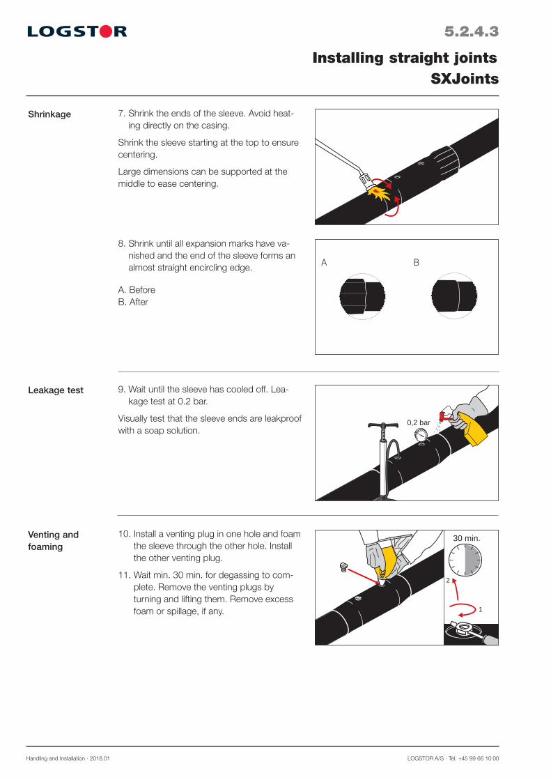
10. Install a venting plug in one hole and foam the sleeve through the other hole. Install the other venting plug.
11. Wait min. 30 min. for degassing to com-plete. Remove the venting plugs by turning and lifting them. Remove excess foam or spillage, if any. 1
2
30 min.
8. Shrink until all expansion marks have va-nished and the end of the sleeve forms an almost straight encircling edge.
A. Before B. After
7. Shrink the ends of the sleeve. Avoid heat-ing directly on the casing.
Shrink the sleeve starting at the top to ensure centering.
Large dimensions can be supported at the middle to ease centering.
A B
0,2 bar
9. Wait until the sleeve has cooled off. Lea-kage test at 0.2 bar.
Visually test that the sleeve ends are leakproof with a soap solution.
Leakage test
Venting and foaming

LOGSTOR A/S · Tel. +45 99 66 10 00 Handling and Installation · 2018.01
5.2.4.4
Installing straight jointsSXJoints
Expansion plugs 13. Remove the protective foil from the ex-pansion plugs and check the mastic.
14. Activate briefly the recessed area with a hard flame.
1-2 sec.
15. Mount the expansion plugs in the ho-les and press until the mastic is spread smoothly under the collar of the plug.
Wedge plugs 16. Centre the wedge plugs in the expansion plugs and drive them completely into the plugs with a hammer.
12. Clean the whole suface of the recessed area around the holes with alcohol. Then grind the area with emery cloth. Remove grind dust, if any.
Venting and foaming,continued
Handling and Installation · 2018.01 LOGSTOR A/S · Tel. +45 99 66 10 00
5.2.4.5
Installing straight jointsSXJoints
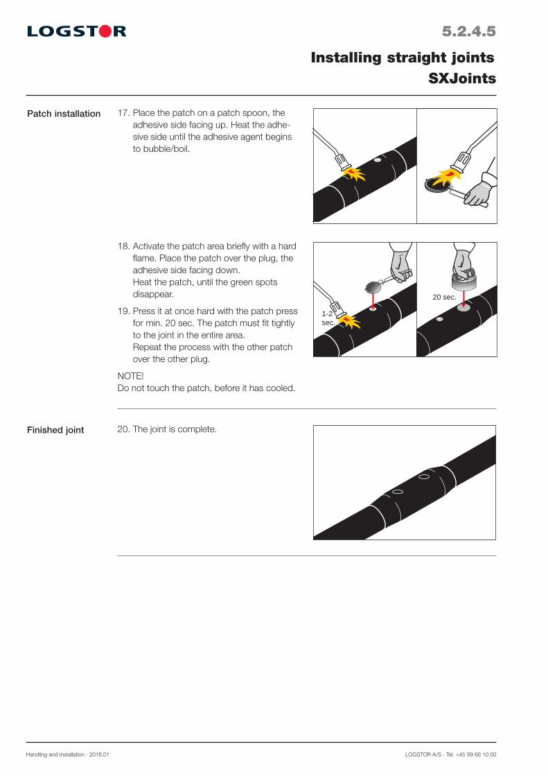
18. Activate the patch area briefly with a hard flame. Place the patch over the plug, the adhesive side facing down. Heat the patch, until the green spots disappear.
19. Press it at once hard with the patch press for min. 20 sec. The patch must fit tightly to the joint in the entire area. Repeat the process with the other patch over the other plug.
NOTE! Do not touch the patch, before it has cooled.
1-2sec.
20 sec.
Patch installation 17. Place the patch on a patch spoon, the adhesive side facing up. Heat the adhe-sive side until the adhesive agent begins to bubble/boil.
20. The joint is complete.Finished joint

LOGSTOR A/S · Tel. +45 99 66 10 00 Handling and Installation · 2018.01
Tools
5.2.5.1
Installing straight jointsSX-WPJoints
Application The SX-WPJoint is a closed shrink joint which is installted prior to welding the service pipe together. It is used for joints on pipes with outer casing dimensions ø 90-450 mm.
The two foam holes are sealed with weld plugs.
General guidelines for trench and casing joint installation, see section 5.1 ”Preparations for joint installation”.
Connecting alarm wires, see sections 23.
Foam pack: – Size, see Product Catalogue section 15 – Further information, see Handling &
Installation section 7.
Preinstallation of casing joint
1. Place the shrink sleeve with packing on one of the pipes before the service pipes are joined.
The following tools must be used when installing SX-WPJoints:
1. Alcohol, min. 93%
2. Emery cloth, grain size 36-60
3. Gloves
4. Gas burner: ø 50 mm: Minor dimensions ø 60 mm: Major dimensions
5. Drilling machine with a ø 35 mm conical mill bit
6. Leakage test equipment
7. Plug welding tool
8. Retaining tool for weld plug
9. Temperature measuring device
1 2 54
6
3
87 9
65°
Handling and Installation · 2018.01 LOGSTOR A/S · Tel. +45 99 66 10 00
5.2.5.2
Installing straight jointsSX-WPJoints
6. Centre the sleeve on the joint. Remove the mastic covering in the shrink sleeve. Make sure that all the foil has been remo-ved.
65°
65°C
5. Activate the contact surfaces with a gas burner to a surface temperature of min. 65°C.
2. All surfaces in the mounting area must be CLEAN and DRY.
Afterwards clean them with alcohol.
3. Remove the packaging from the shrink sleeve. Check that the sleeve is DRY and CLEAN inside and out.
4. Grind the contact surfaces of the shrink sleeve with emery cloth, so grind marks are visible outside the sleeve rim (This enables visual control of the grinding by the inspection).
Remove grind dust, if any.
Avoid touching the ground contact sur-faces.
Cleaning
Activation
Positioning shrink sleeve
LOGSTOR A/S · Tel. +45 99 66 10 00 Handling and Installation · 2018.01
5.2.5.3
Installing straight jointsSX-WPJoints
Shrinkage
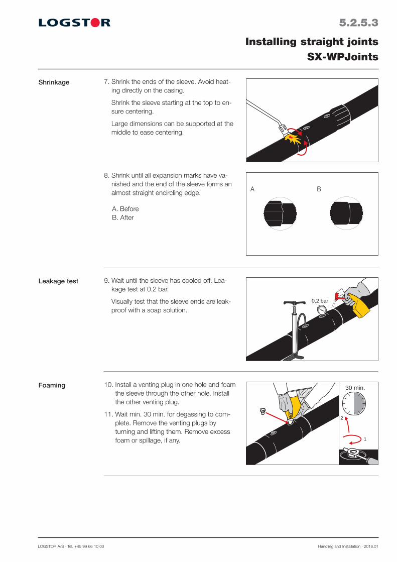
10. Install a venting plug in one hole and foam the sleeve through the other hole. Install the other venting plug.
11. Wait min. 30 min. for degassing to com-plete. Remove the venting plugs by turning and lifting them. Remove excess foam or spillage, if any. 1
2
30 min.
8. Shrink until all expansion marks have va-nished and the end of the sleeve forms an almost straight encircling edge.
A. Before B. After
7. Shrink the ends of the sleeve. Avoid heat-ing directly on the casing.
Shrink the sleeve starting at the top to en-sure centering.
Large dimensions can be supported at the middle to ease centering.
A B
0,2 bar
9. Wait until the sleeve has cooled off. Lea-kage test at 0.2 bar.
Visually test that the sleeve ends are leak-proof with a soap solution.
Leakage test
Foaming
Handling and Installation · 2018.01 LOGSTOR A/S · Tel. +45 99 66 10 00
5.2.5.4
Installing straight jointsSX-WPJoints
Weld plug
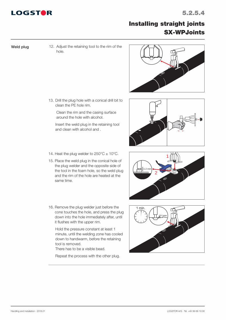
16. Remove the plug welder just before the cone touches the hole, and press the plug down into the hole immediately after, until it flushes with the upper rim.
Hold the pressure constant at least 1 minute, until the welding zone has cooled down to handwarm, before the retaining tool is removed. There has to be a visible bead.
Repeat the process with the other plug.
1-2 mm
1
2
12. Adjust the retaining tool to the rim of the hole.
14. Heat the plug welder to 250°C ± 10°C.
15. Place the weld plug in the conical hole of the plug welder and the opposite side of the tool in the foam hole, so the weld plug and the rim of the hole are heated at the same time.
13. Drill the plug hole with a conical drill bit to clean the PE hole rim.
Clean the rim and the casing surface around the hole with alcohol.
Insert the weld plug in the retaining tool and clean with alcohol and .

LOGSTOR A/S · Tel. +45 99 66 10 00 Handling and Installation · 2018.01
5.2.5.5
Installing straight jointsSX-WPJoints
17. The joint is complete.Finished joint

Handling and Installation · 2018.01 LOGSTOR A/S · Tel. +45 99 66 10 00
5.2.6.1
Installing straight jointsBXJoints
Application The BXJoint is a closed shrink joint, installed prior to welding the service pipe together. It is used to join pipes with outer casing dimen-sions ø 90-630 mm.
BXJoints can also be foamed in alu-wrap, see Installation of BXSJoint.
General guidelines for pipes and casing joint installation, see section 5.1 ”Preparations for joint installation”.
Connecting alarm wires, see sections 23.3 and 23.4.
Preinstallation of casing joint
1. Place the shrink sleeve with packing on one of the pipes, before the service pipes are joined.
2. All surfaces in the mounting area must be CLEAN and DRY
Tools The following tools must be used when installing BXJoints:
Cleaning
1. Alcohol, min. 93%
2. Emery cloth, grain size 36-60
3. Gloves
4. Gas burner: ø 50 mm: Minor dimensions ø 60 mm: Major dimensions
5. Saw
6. Temperature measuring device
5
4
1 2 3
65°
6
LOGSTOR A/S · Tel. +45 99 66 10 00 Handling and Installation · 2018.01
5.2.6.2
Installing straight jointsBXJoints
Adjusting insula-tion shells
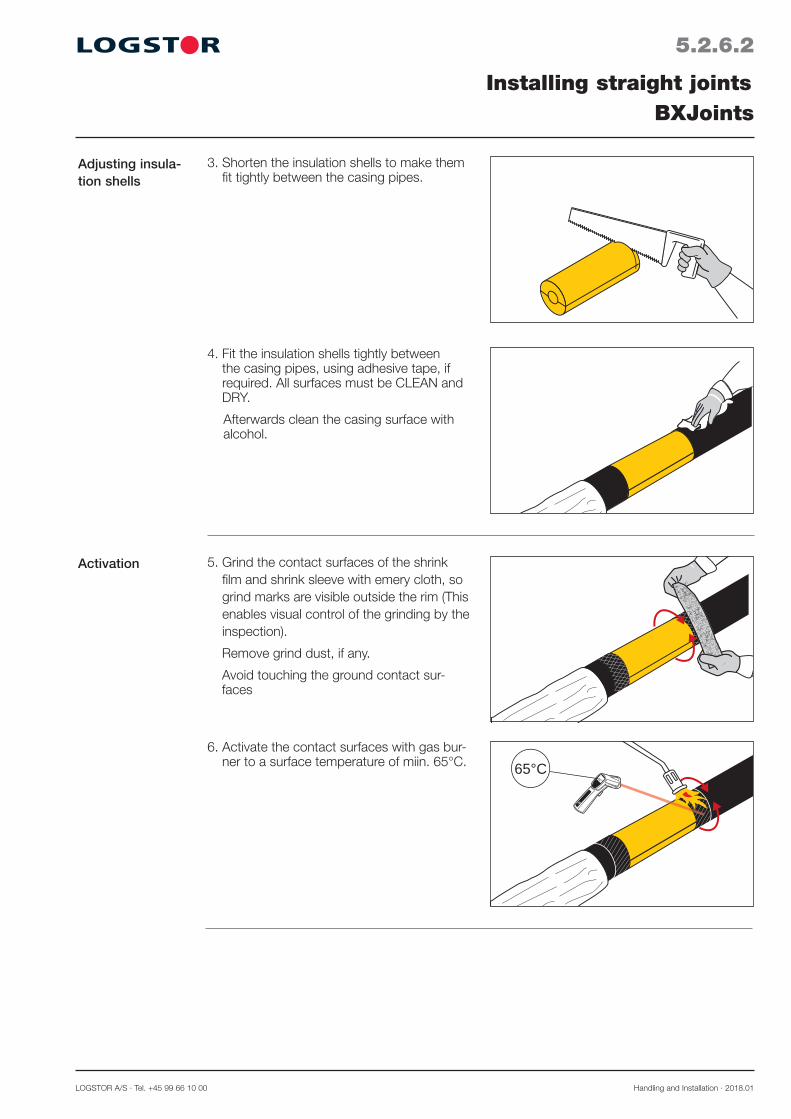
4. Fit the insulation shells tightly between the casing pipes, using adhesive tape, if required. All surfaces must be CLEAN and DRY.
Afterwards clean the casing surface with alcohol.
5. Grind the contact surfaces of the shrink film and shrink sleeve with emery cloth, so grind marks are visible outside the rim (This enables visual control of the grinding by the inspection).
Remove grind dust, if any.
Avoid touching the ground contact sur- faces
6. Activate the contact surfaces with gas bur-ner to a surface temperature of miin. 65°C.
65°
65°C
3. Shorten the insulation shells to make them fit tightly between the casing pipes.
Activation

Handling and Installation · 2018.01 LOGSTOR A/S · Tel. +45 99 66 10 00
5.2.6.3
Installing straight jointsBXJoints
Installing shrink film
10. Remove the packing from the shrink sle-eve. Check that the sleeve is CLEAN and DRY, inside and out.
11. Centre the shrink sleeve on the joint. Remove the mastic cover in the shrink sleeve and make sure that all the foil has been removed.
7. Centre the shrink film on the joint and place it around the pipe. Attach one edge of the shrink film in "10 o’clock" position.
8. Pull the film around the pipe by removing the adhesive paper so that the film adheres to the surface beneath it.
9. Heat the whole film from the centre to-wards the sides, ensuring that the shrink film is tightly fitted.
Positioning shrink sleeve

LOGSTOR A/S · Tel. +45 99 66 10 00 Handling and Installation · 2018.01
12. Srink the sleevefrom the middle towards one end, then from the middle towards the other end. Avoid heating directly on the casing.
13. Shrink until all expansion marks have va-nished and the end of the sleeve forms an almost straight encircling edge.
A. Before B. After
14. The joint is complete.
A B
5.2.6.4
Installing straight jointsBXJoints
Shrinkage
Finished joint

Handling and Installation · 2018.01 LOGSTOR A/S · Tel. +45 99 66 10 00
5.2.7.1
Installing straight jointsB2SJoints
Application The B2SJoint is a closed joint to be installed before the service pipes are welded together.
B2SJoints are used to join pipes, when a double sealing shrink joint is required in thed-imensional range ø 90-1000 mm.
The two foam holes are sealed with expan-sion and wedge plugs as well as patches. Alternatively, they can be sealed with weld plugs.
General instructions for the trench and the joint installation, see section 5.1 “Preparations for joint installation”.
As for connection of alarm wires, see sec-tions 23.
Foam packs: - Size, see Product Catalogue section 15 - Further information, see Handling &
Installation section 7.
Tools
Remove the loose components of the joint from the packing and store them in a dry environment, until later installation.
1. Place the shrink sleeve with packaging on one of the pipes, before the service pipes are joined.
Preinstallation of casing joint
The following tools must be used when installing B2SJoints:
1. Alcohol, min 93%
2. Emery cloth, grain size 36-60
3. Gloves
4. Gas burner: ø 50 mm: Minor dimensions ø 60 mm: Major dimensions
5. Drilling machine with 25 mm drill
6. Leakage test equipment
7. Hammer
8. Patch spoon
9. Patch press
10. Temperature measuring device
1 2 54
6
3
879 65°
10
LOGSTOR A/S · Tel. +45 99 66 10 00 Handling and Installation · 2018.01
5.2.7.2
Installing straight jointsB2SJoints
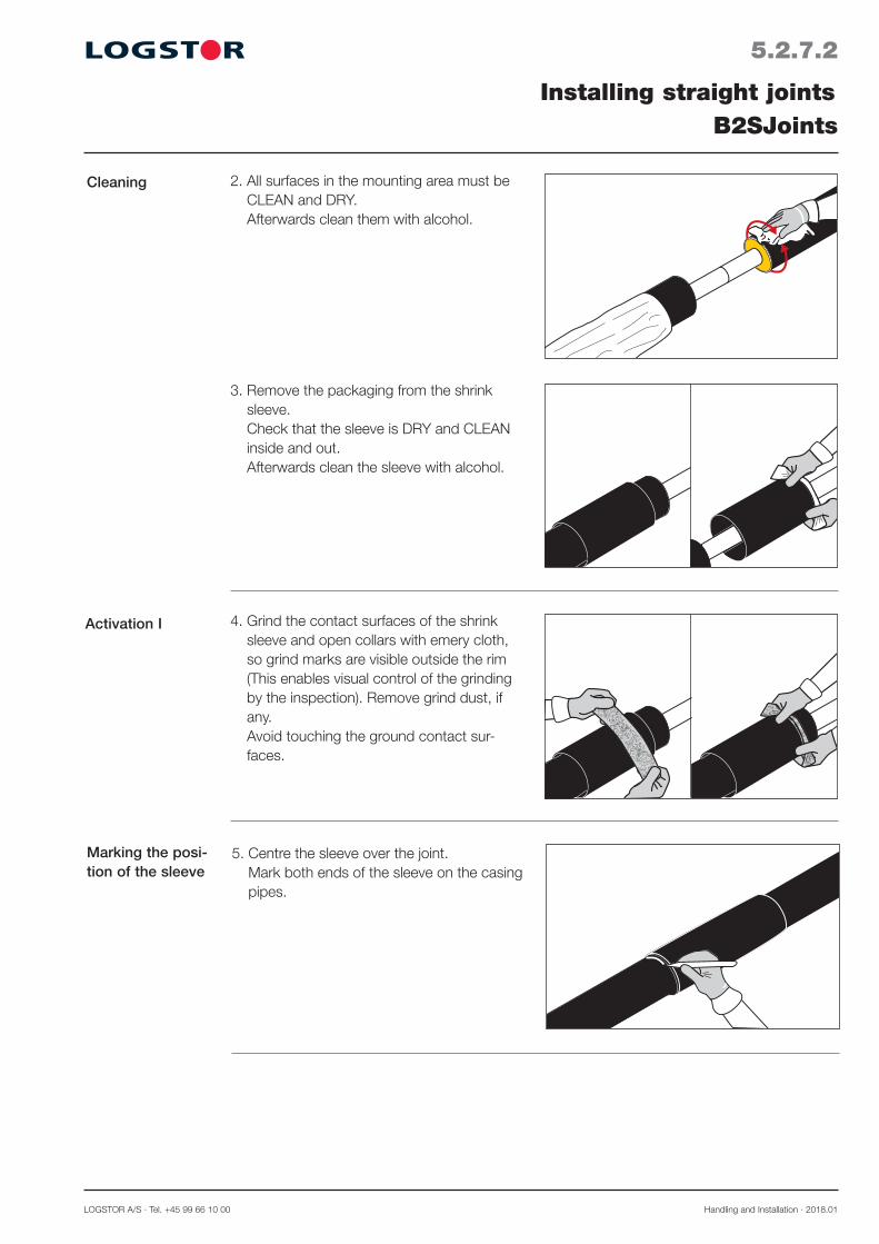
Cleaning 2. All surfaces in the mounting area must be CLEAN and DRY. Afterwards clean them with alcohol.
4. Grind the contact surfaces of the shrink sleeve and open collars with emery cloth, so grind marks are visible outside the rim (This enables visual control of the grinding by the inspection). Remove grind dust, if any. Avoid touching the ground contact sur-faces.
Activation I
3. Remove the packaging from the shrink sleeve. Check that the sleeve is DRY and CLEAN inside and out. Afterwards clean the sleeve with alcohol.
Marking the posi-tion of the sleeve
5. Centre the sleeve over the joint. Mark both ends of the sleeve on the casing pipes.
Handling and Installation · 2018.01 LOGSTOR A/S · Tel. +45 99 66 10 00
5.2.7.3
Installing straight jointsB2SJoints
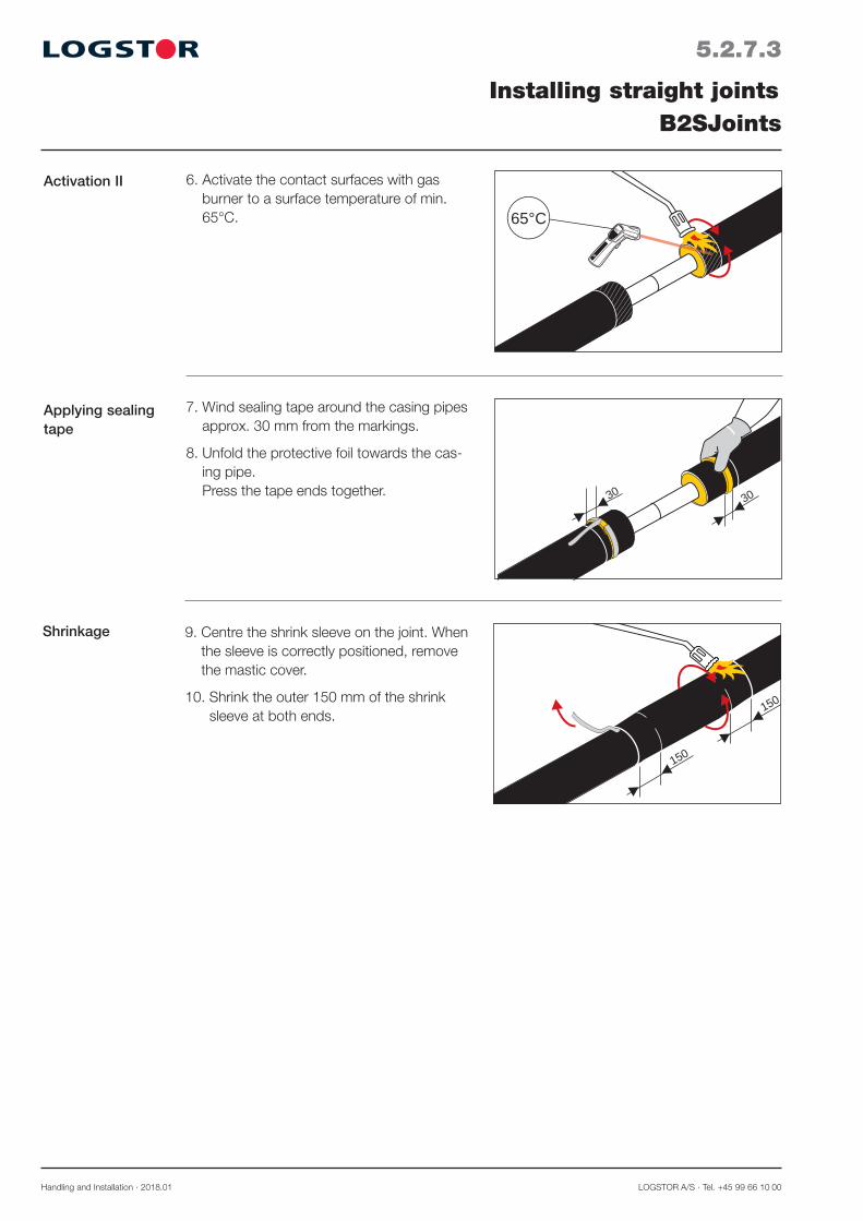
6. Activate the contact surfaces with gas burner to a surface temperature of min. 65°C.
65°
65°C
7. Wind sealing tape around the casing pipes approx. 30 mm from the markings.
8. Unfold the protective foil towards the cas-ing pipe. Press the tape ends together.
3030
Applying sealing tape
Shrinkage 9. Centre the shrink sleeve on the joint. When the sleeve is correctly positioned, remove the mastic cover.
10. Shrink the outer 150 mm of the shrink sleeve at both ends.
150
150
Activation II

LOGSTOR A/S · Tel. +45 99 66 10 00 Handling and Installation · 2018.01
5.2.7.4
Installing straight jointsB2SJoints
14. Install a venting plug in one of the holes and foam the sleeve through the other one. Install the other venting plug. Wait min. 30 min. for degassing. Remove the venting plugs by turning and lifting them. Remove excess foam or spillage, if any.
Foaming
13. Drill two ø 25 mm holes - one at each sleeve end at the summit as close to the casing ends as possible.
When the shrink sleeve has cooled to max. handwarm leakage test with 0.2 bar.
Test the sleeve ends visually with soapy water.
Leakage test
0,2 bar
1
2
30 min.
11. Centre a collar (bevelled corners) on one shrink sleeve end, so the fat end of the symbol faces the sleeve. Install the collar around the sleeve end with an overlap of 50 mm. Centre the closure patch over the joint of the collar. Heat the closure patch, until the net struc-ture can be seen on the upper side. Press down the closure patch.
12. Shrink the collar with a gas burner, moving from the shrink sleeve towards the casing pipe. The sealing compound must be visible at both sides in the entire circumference. After shrinkage the surface structure must be smooth.
Repeat with the other collar over the other sleeve end.
Shrinkage,continued
Handling and Installation · 2018.01 LOGSTOR A/S · Tel. +45 99 66 10 00
5.2.7.5
Installing straight jointsB2SJoints
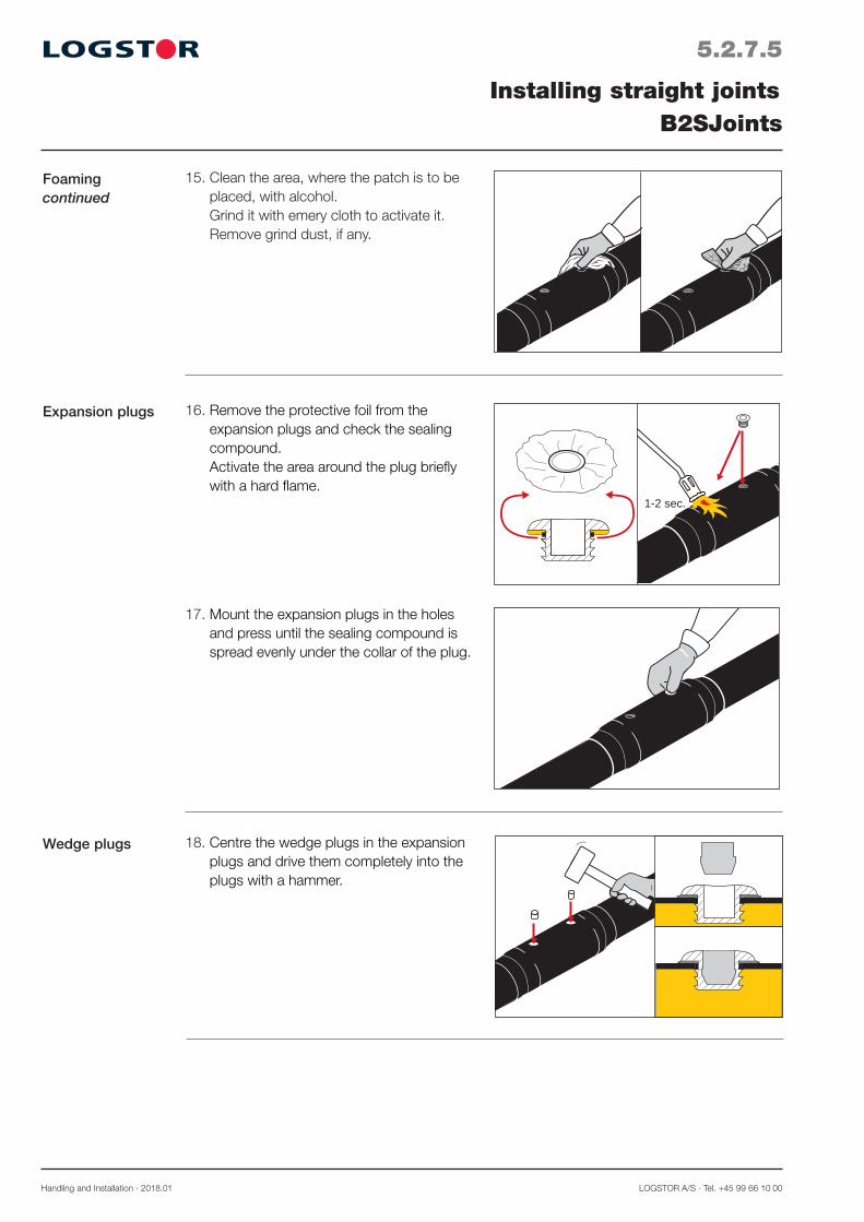
18. Centre the wedge plugs in the expansion plugs and drive them completely into the plugs with a hammer.
Wedge plugs
16. Remove the protective foil from the expansion plugs and check the sealing compound. Activate the area around the plug briefly with a hard flame.
1-2 sec.
Expansion plugs
17. Mount the expansion plugs in the holes and press until the sealing compound is spread evenly under the collar of the plug.
Foamingcontinued
15. Clean the area, where the patch is to be placed, with alcohol. Grind it with emery cloth to activate it. Remove grind dust, if any.

LOGSTOR A/S · Tel. +45 99 66 10 00 Handling and Installation · 2018.01
5.2.7.6
Installing straight jointsB2SJoints
20. Activate the patch area briefly, 1-2 sec., with a hard flame. Place the patch over the plug, the adhesive side facing down.
21. Heat the patch until the green spots disappear. Press it at once hard with the patch-press for min. 20 sec. The patch must fit tightly to the joint in the entire area. Repeat the process with the other patch over the other plug.
NOTE! Do not touch the patch, before it has cooled.
1-2sec.
20 sec.
19. Place the patch on a patch-spoon, the adhesive side facing up. Heat the adhe-sive side until the glue begins to bubble/boil.
Patch installation
22. The joint is complete.Finished joint
Handling and Installation · 2018.01 LOGSTOR A/S · Tel. +45 99 66 10 00
5.2.8.1
Installing straight jointsBSJoints
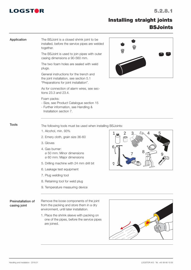
Application The BSJoint is a closed shrink joint to be installed, before the service pipes are welded together.
The BSJoint is used to join pipes with outer casing dimensions ø 90-560 mm.
The two foam holes are sealed with weld plugs.
General instructions for the trench and the joint installation, see section 5.1 “Preparations for joint installation”.
As for connection of alarm wires, see sec-tions 23.3 and 23.4.
Foam packs: - Size, see Product Catalogue section 15 - Further information, see Handling &
Installation section 7.
Tools
Remove the loose components of the joint from the packing and store them in a dry environment, until later installation.
1. Place the shrink sleeve with packing on one of the pipes, before the service pipes are joined.
The following tools must be used when installing BSJoints:
1. Alcohol, min. 93%
2. Emery cloth, grain size 36-60
3. Gloves
4. Gas burner: ø 50 mm: Minor dimensions ø 60 mm: Major dimensions
5. Drilling machine with 24 mm drill bit
6. Leakage test equipment
7. Plug welding tool
8. Retaining tool for weld plug
9. Temperature measuring device
1 2 54
6
3
87 9
65°
Preinstallation of casing joint

LOGSTOR A/S · Tel. +45 99 66 10 00 Handling and Installation · 2018.01
5.2.8.2
Installing straight jointsBSJoints
Activation I
3. Remove the packaging from the shrink sleeve. Check that the sleeve is DRY and CLEAN inside and out. Afterwards clean the sleeve with alcohol.
4. Grind the internal contact surfaces of the shrink sleeve with emery cloth, so grind marks are visible outside the sleeve rim (This enables visual control of the grinding by the inspection). Remove grind dust, if any. Avoid touching the ground contact sur-faces.
5. Centre the sleeve over the joint. Mark both ends of the sleeve on the casing pipes.
Marking the posi-tion of the sleeve
2. All surfaces in the mounting area must be CLEAN and DRY. Afterwards clean them with alcohol.
Cleaning

Handling and Installation · 2018.01 LOGSTOR A/S · Tel. +45 99 66 10 00
5.2.8.3
Installing straight jointsBSJoints
Shrinkage 9. Centre the shrink sleeve on the joint. When the sleeve is correctly positioned, remove the paper from the sealing tape.
10. Shrink the outer 150 mm of the shrink sleeve at both ends. 150
150
7. Wind sealing tape around the casing pipes approx. 30 mm from the markings.
8. Unfold the protective foil towards the cas-ing pipe. Press the tape ends together.
3030
Applying sealing tape
11. Drill 2 holes (ø24 mm) - one at each sleeve end at the summit as close to the casing ends as possible. When the shrink sleeve is hand-warm leakage test with 0.2 bar. Inspect the ends visually with soapy water.
Leakage test
0,2 bar
65°
65°C
6. Activate the contact surfaces with a gas burner to a surface temperature of min. 65°C.
Activation II
LOGSTOR A/S · Tel. +45 99 66 10 00 Handling and Installation · 2018.01
5.2.8.4
Installing straight jointsBSJoints
1 min.
0-1 mm
Weld plug
10 sec.
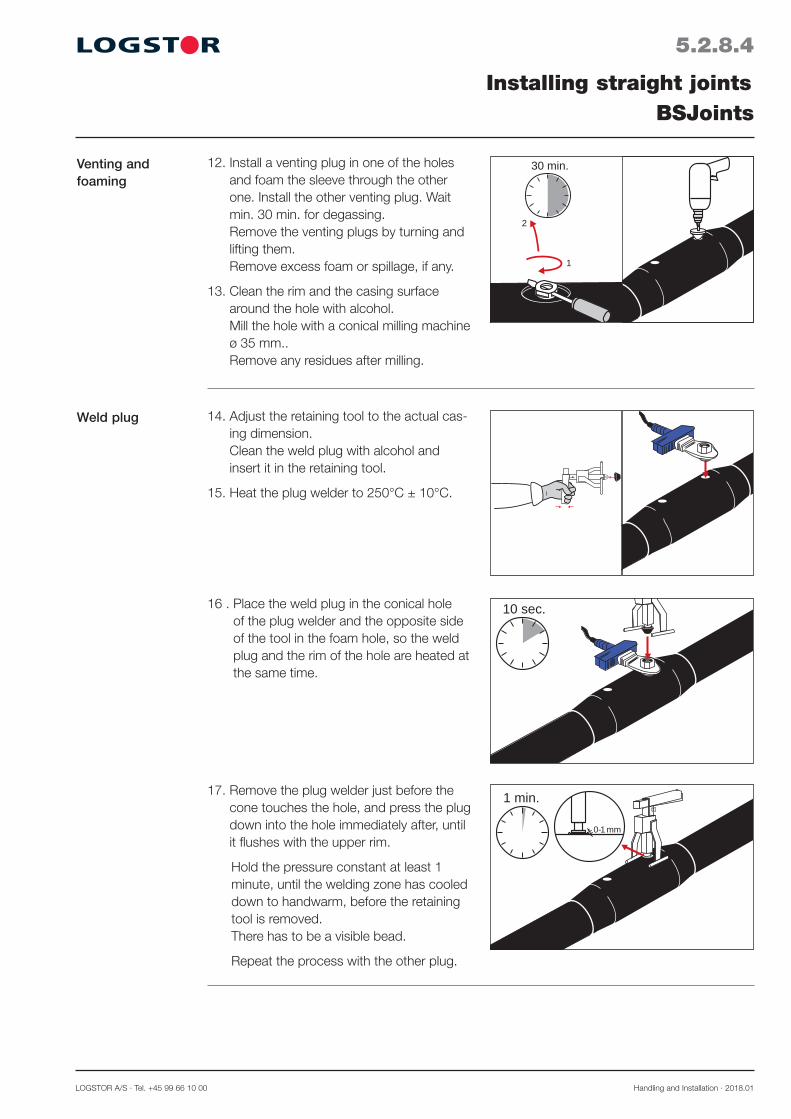
12. Install a venting plug in one of the holes and foam the sleeve through the other one. Install the other venting plug. Wait min. 30 min. for degassing. Remove the venting plugs by turning and lifting them. Remove excess foam or spillage, if any.
13. Clean the rim and the casing surface around the hole with alcohol. Mill the hole with a conical milling machine ø 35 mm.. Remove any residues after milling.
Venting and foaming
1
2
30 min.
17. Remove the plug welder just before the cone touches the hole, and press the plug down into the hole immediately after, until it flushes with the upper rim.
Hold the pressure constant at least 1 minute, until the welding zone has cooled down to handwarm, before the retaining tool is removed. There has to be a visible bead.
Repeat the process with the other plug.
14. Adjust the retaining tool to the actual cas-ing dimension. Clean the weld plug with alcohol and insert it in the retaining tool.
15. Heat the plug welder to 250°C ± 10°C.
16 . Place the weld plug in the conical hole of the plug welder and the opposite side of the tool in the foam hole, so the weld plug and the rim of the hole are heated at the same time.

Handling and Installation · 2018.01 LOGSTOR A/S · Tel. +45 99 66 10 00
5.2.8.5
Installing straight jointsBSJoints
18. The joint is complete.Finished joint

LOGSTOR A/S · Tel. +45 99 66 10 00 Handling and Installation · 2018.01
5.2.9.0
Installing straight jointsRepair joints
Joints suitable for repair
All open joint types are suitable for repair within their dimensional range.
Welded joints: BandJoints, ø 90-710 mm See section 5.2.1 PlateJoint ø 780-1400 mm See section 5.2.2
Shrink joints: C2LJoint, ø 90-630 mm See section, 5.2.9.1

Handling and Installation · 2018.01 LOGSTOR A/S · Tel. +45 99 66 10 00
5.2.9.1
Installing straight jointsC2LJoints
Application C2LJoints are used, when there is not enough space to pre-install a shrink joint, e.g. where two short bends are used immediately after each other or as a repair joint. C2LJoint are as a standard used with insulation shells for outer casing dimensions ø 90-630 mm.
Instead of insulation shells foaming in alu-wrap is possible. Foaming in alu-wrap is always done in connection with dimensions > 630 mm. As regards foaming in alu-wrap, see section 7.7.
General instructions for the trench and the joint installation, see section 5.1 ”Preparations for joint installation”.
As for connection of alarm wires, see sec-tions 23.3 and 23.4.
1. All surfaces in the mounting area must be CLEAN and DRY.
1 2
5
4
6
3
7
65°
Tools
Cleaning
The following tools must be used when install-ing C2LJoints:
1. Alcohol, min. 93%
2. Emery cloth, grain size 36-60
3. Gloves
4. Gas burner: ø 50 mm: Minor dimensions ø 60 mm: Major dimensions
5. Saw
6. Roller
7. Temperature measuring device

LOGSTOR A/S · Tel. +45 99 66 10 00 Handling and Installation · 2018.01
2. Shorten the insulation shells to make them fit tightly between the casing pipes.
3. Fit the insulation shells tightly between the casing pipes, using adhesive tape if required. All surfaces must be CLEAN and DRY. Afterwards clean the casing surfaces with alcohol.
Adjusting insula-tion shells
5.2.9.2
Installing straight jointsC2LJoints
Activation 4. Grind the contact surfaces of the shrink sleeve and wrap with emery cloth, so grind marks are visible outside the rim (This enables visual control of the grinding by the inspection). Remove grind dust, if any. Avoid touching the ground contact sur-faces.
65°
65°C
5. Activate the contact surfaces with gas burner to a surface temperature of min. 65°C.

Handling and Installation · 2018.01 LOGSTOR A/S · Tel. +45 99 66 10 00
Installing shrink film
5.2.9.3
Installing straight jointsC2LJoints
6. Centre the shrink film on the joint and place it around the pipe. Attach one edge of the shrink film in the "10 o’clock" position. Pull the film around the pipe by removing the adhesive paper so that the film adheres to the surface beneath it.
7. Heat the whole film from the centre to-wards the sides, ensuring that the shrink film is tightly fitted.
8. Remove the packaging from the shrink sleeve. Check that the sleeve is DRY and CLEAN inside and out. Open the shrink sleeve by cutting it longi-tudinally. Clean the sleeve with alcohol.Then place the shrink sleeve over the joint. Centre the shrink sleeve on the joint. The longitudinal cut of the sleeve must be on the top and its edges must adjoin.
Installing shrink sleeve
9. Centre the closure patch on the shrink sleeve cut with the hotmelt facing down-wards. The side with the hotmelt has vis-ible reinforcement. Heat the closure patch until the structure of reinforcement becomes visible on the topside. Press down the closure patch. Then roll on the closure patch with the roller to ensure a good adhesion.

LOGSTOR A/S · Tel. +45 99 66 10 00 Handling and Installation · 2018.01
Shrinking sleeve
5.2.9.4
Installing straight jointsC2LJoints
10. If necessary, turn the sleeve, so that the closure patch is in a "10 o'clock posi-tion". Shrink the sleeve with longitudinal sweeping movements from one end to the other.
11. Check the activation temperature of the contact surfaces prior to installing the shrink wrap. The temperature must be min. 65°C. Remove the protective foil from the shrink wrap, while pulling the wrap into position. Make sure that the text on the wrap en-circles the pipe and that the wrap closes at the top. The wrap must fit loosely around the pipe with an overlap of min 50 mm.
12. Centre the closure patch right above the wrap seam. Fasten as described under item 9.
13. Shrink the wrap from the centre towards the ends. Shrink until the mastic becomes visible at all edges and the entire wrap adheres to the underlying surface. After shrinkage the surface structure of the shrink wrap must be smooth and the green heat indicators must be heated, until they disappear.
Installing shrink wrap
65°
65°C
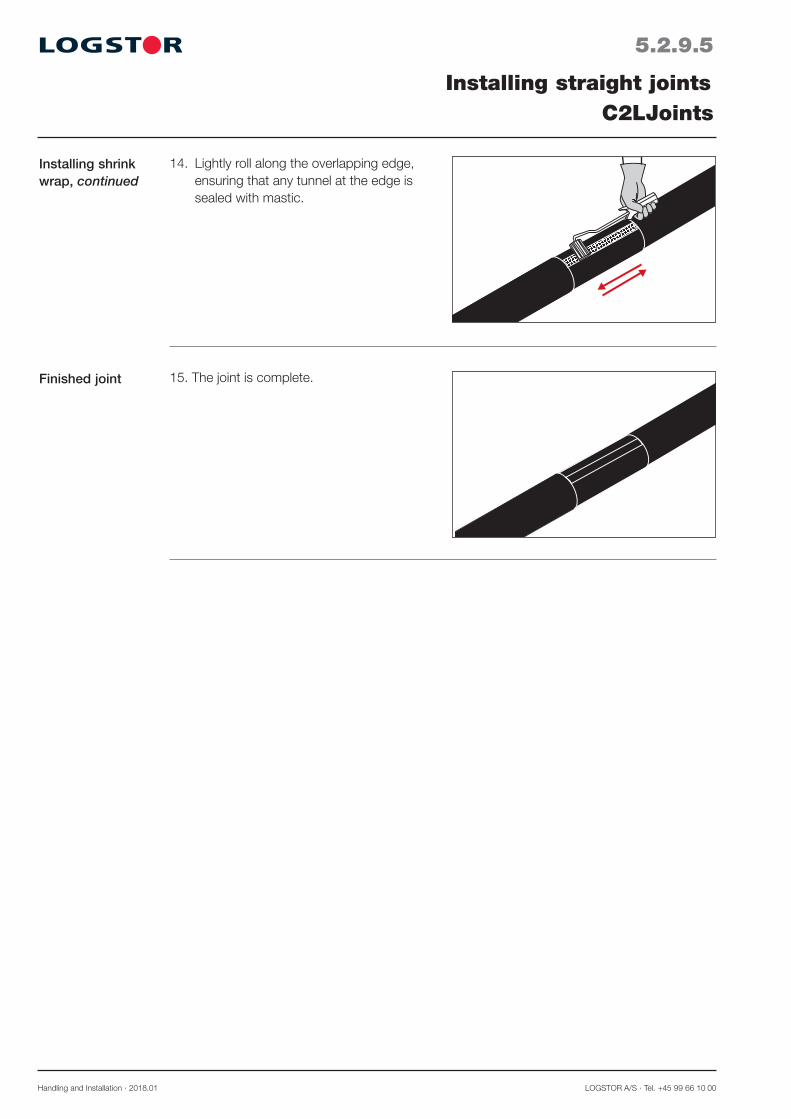
Handling and Installation · 2018.01 LOGSTOR A/S · Tel. +45 99 66 10 00
Installing shrink wrap, continued
5.2.9.5
Installing straight jointsC2LJoints
14. Lightly roll along the overlapping edge, ensuring that any tunnel at the edge is sealed with mastic.
15. The joint is complete.Finished joint

LOGSTOR A/S · Tel. +45 99 66 10 00 Handling and Installation · 2018.01
5.3.0.1
Introduction
Contents
Installing bendsOverview
This section contains instructions for installing bends.
SXBJoint 5.3.1SXB-WPJoint 5.3.2Prefabricated bends 5.3.3

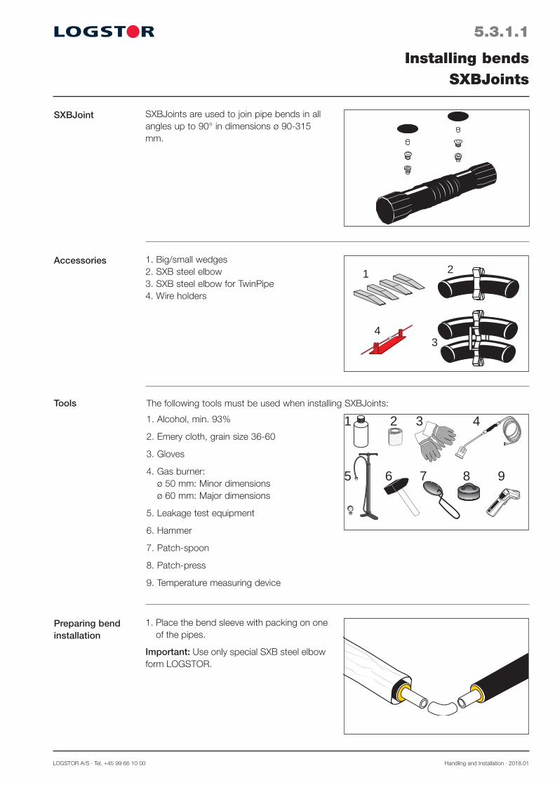
LOGSTOR A/S · Tel. +45 99 66 10 00 Handling and Installation · 2018.01
5.3.1.1
SXBJoint
Installing bendsSXBJoints
SXBJoints are used to join pipe bends in all angles up to 90° in dimensions ø 90-315 mm.
Accessories 1. Big/small wedges 2. SXB steel elbow 3. SXB steel elbow for TwinPipe4. Wire holders
Tools
1. Place the bend sleeve with packing on one of the pipes.
Important: Use only special SXB steel elbow form LOGSTOR.
Preparing bend installation
1 2
34
The following tools must be used when installing SXBJoints:
1. Alcohol, min. 93%
2. Emery cloth, grain size 36-60
3. Gloves
4. Gas burner: ø 50 mm: Minor dimensions ø 60 mm: Major dimensions
5. Leakage test equipment
6. Hammer
7. Patch-spoon
8. Patch-press
9. Temperature measuring device
4
5 6
1 2 3
7 8
65°
9

Handling and Installation · 2018.01 LOGSTOR A/S · Tel. +45 99 66 10 00
5.3.1.2
Weld elbow
Installing bendsSXBJoints
4. Measure from the welds and mark the length L on both casing pipes. The marks must be very distinctive. L is found in the tables on the last pages of this section.
To make foaming possible the free pipe ends generally have to be extended.
Measure 115 mm back from the marking L and cut off insulation.
Place the spacer in the middle of the bend. The beveled edge must face the bend sleeve.
L 115
5. Place the wire retainers and the alarm wires in „1 o’clock“ and „11 o’clock“ position on the service pipe. Check that the alarm wi-res do not touch the service pipe. Also see section 23 as regards joining alarm wires Be careful not to damage or displace the alarm wires during installation of the joint.
2. Cut the weld elbow at the wanted angle. Weld the steel elbow to the two pipe ends.
TwinPipe: It is important to mount the two SXB steel elbows parallel to each other and perpendicularly to the TwinPipe to facilitate the installation.
3. All surfaces in the mounting area must be CLEAN and DRY. Afterwards clean with alcohol.
Cleaning
Marking joint position Adjusting free ends
Alarm wires

LOGSTOR A/S · Tel. +45 99 66 10 00 Handling and Installation · 2018.01
5.3.1.3
Preheating bend joint
Installing bendsSXBJoints
9. Place the sleeve above the SXB steel el-bow, so the ends exactly meet the marks. Pull and push the sleeve around the elbow. Press the corrugation opposite the spacer if it gets stuck. Check that the foaming holes are not cove-red by the outer casing. Place the wedges under the ends of the sleeve, at the sides and at the bottom to ensure centering. Let the bend cool down, until it is stiff. Remove wedges and covering from the sleeve ends.
8. Heat the corrugation with a gas burner. Avoid heating on the smooth ends. Continue until the corrugation is so flexible that it can easily be compressed manually. Extend it again.
6. Remove the packaging from the shrink sleeve. Check that the sleeve is DRY and CLEAN inside and out. Grind the contact surfaces of the shrink sleeve with emery cloth, so grind marks are visible outside the sleeve rim (This enables visual control of the grinding by the inspec-tion). Remove grind dust, if any. Avoid touching the ground contact sur-faces.
Positioning and shrinking bend joint
Activation
7. Activate the contact surfaces with a gas burner to a surface temperature of min. 65°C.
65°
65°C
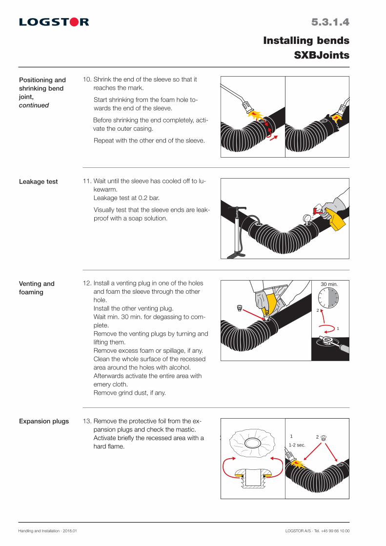
Handling and Installation · 2018.01 LOGSTOR A/S · Tel. +45 99 66 10 00
5.3.1.4
Leakage test
Installing bendsSXBJoints
11. Wait until the sleeve has cooled off to lu-kewarm. Leakage test at 0.2 bar.
Visually test that the sleeve ends are leak-proof with a soap solution.
12. Install a venting plug in one of the holes and foam the sleeve through the other hole. Install the other venting plug. Wait min. 30 min. for degassing to com-plete. Remove the venting plugs by turning and lifting them. Remove excess foam or spillage, if any. Clean the whole surface of the recessed area around the holes with alcohol. Afterwards activate the entire area with emery cloth. Remove grind dust, if any.
1
2
30 min.
13. Remove the protective foil from the ex-pansion plugs and check the mastic. Activate briefly the recessed area with a hard flame.
1
1-2 sec.
2 1
1-2 sec.
2
Venting and foaming
Expansion plugs
10. Shrink the end of the sleeve so that it reaches the mark.
Start shrinking from the foam hole to-wards the end of the sleeve.
Before shrinking the end completely, acti-vate the outer casing.
Repeat with the other end of the sleeve.
Positioning and shrinking bend joint,continued

LOGSTOR A/S · Tel. +45 99 66 10 00 Handling and Installation · 2018.01
5.3.1.5
Expansion plugs, continued
Installing bendsSXBJoints
15. Centre the wedge plugs in the expansion plugs and drive them completely into the plugs with a hammer.
16. Place the patch on a patch-spoon, the adhesive side facing up. Heat the adhesive side, until it begins to bubble/boil.
17. Activate briefly, 1-2 sec., the patch area with a hard flame. Place the patch over the plug, the adhesive side facing down. Heat the patch, until the green spots disappear. Press it at once hard with the patch-press for min. 20 sec. The patch must fit tightly to the joint in the entire area and the ad-hesive agent must be visible all around the patch. Repeat the process with the other patch over the other plug.
Note! Do not touch the patch, before it has cooled.
20 sec.
Patch installation
14. Mount the expansion plugs in the holes and press, so the mastic becomes visible all the way round.
Drive the expansion plugs completely in, using a hammer.
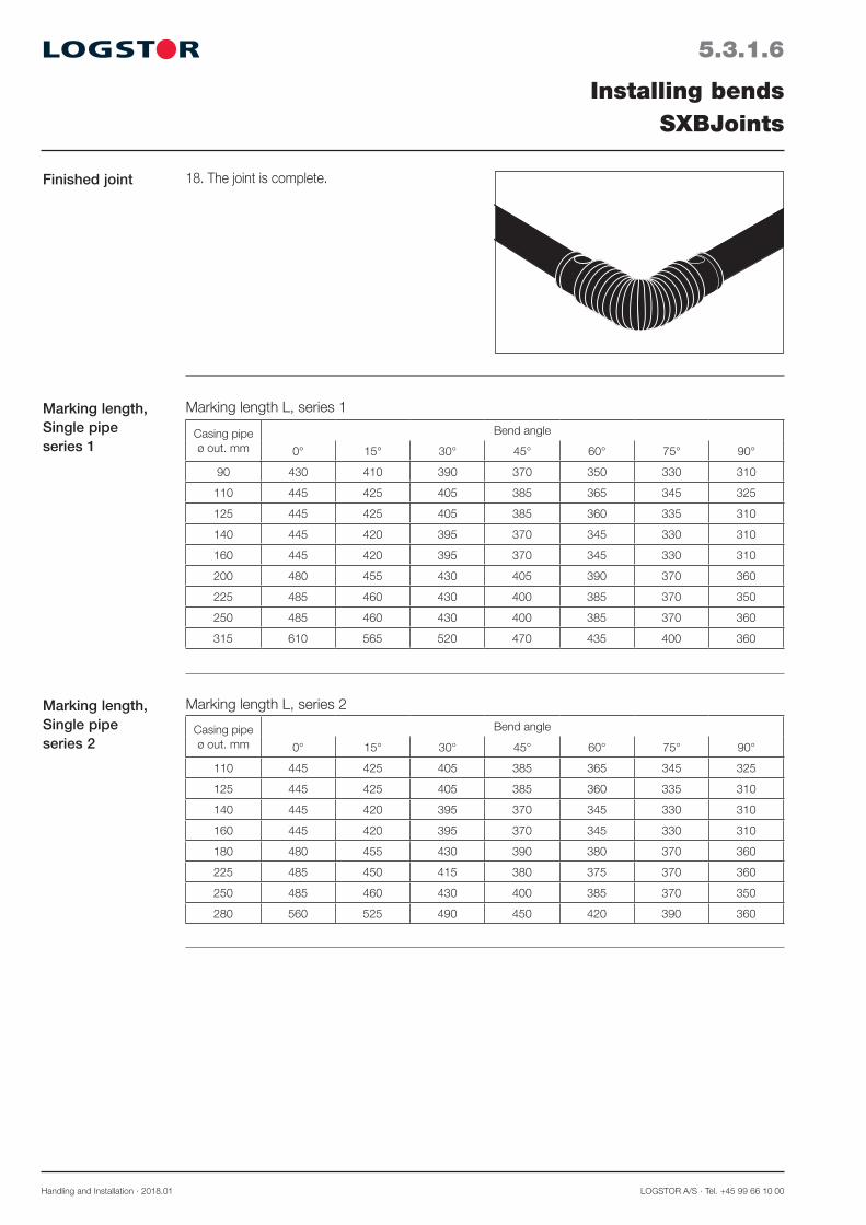
Handling and Installation · 2018.01 LOGSTOR A/S · Tel. +45 99 66 10 00
5.3.1.6
Installing bendsSXBJoints
Marking length L, series 1Marking length, Single pipeseries 1
Marking length L, series 2Marking length, Single pipe series 2
Casing pipeø out. mm
Bend angle
0° 15° 30° 45° 60° 75° 90°
90 430 410 390 370 350 330 310
110 445 425 405 385 365 345 325
125 445 425 405 385 360 335 310
140 445 420 395 370 345 330 310
160 445 420 395 370 345 330 310
200 480 455 430 405 390 370 360
225 485 460 430 400 385 370 350
250 485 460 430 400 385 370 360
315 610 565 520 470 435 400 360
Casing pipeø out. mm
Bend angle
0° 15° 30° 45° 60° 75° 90°
110 445 425 405 385 365 345 325
125 445 425 405 385 360 335 310
140 445 420 395 370 345 330 310
160 445 420 395 370 345 330 310
180 480 455 430 390 380 370 360
225 485 450 415 380 375 370 360
250 485 460 430 400 385 370 350
280 560 525 490 450 420 390 360
18. The joint is complete.Finished joint

LOGSTOR A/S · Tel. +45 99 66 10 00 Handling and Installation · 2018.01
5.3.1.7
Installing bendsSXBJoints
Marking length, TwinPipe, series 2
TwinPipe: Marking length L, series 2
TwinPipe: Marking length L, series 1Marking length, TwinPipe, series 1
Casing pipeø out. mm
Bend angle
0° 15° 30° 45° 60° 75° 90°
125 445 425 405 385 365 345 320
140 445 425 405 385 365 345 320
160 445 425 405 385 360 335 310
200 480 455 430 405 390 370 350
225 485 450 415 380 370 360 345
250 485 455 425 390 375 360 340
315 610 570 530 485 450 410 370
Marking length, TwinPipe, series 3
TwinPipe: Marking length L, series 3
Outer casing ø out. mm
Bend angle
0° 15° 30° 45° 60° 75° 90°
160 445 425 405 385 365 345 320
180 480 450 420 395 375 355 335
200 480 455 430 405 390 370 350
250 485 455 430 405 390 370 355
280 610 570 530 485 450 410 370
315 610 565 520 475 430 390 350
Outer casing ø out. mm
Bend angle
0° 15° 30° 45° 60° 75° 90°
140 445 425 405 385 365 345 320
160 445 425 405 385 365 345 320
180 480 455 430 405 390 370 350
225 485 455 430 405 390 370 355
250 485 450 415 380 370 360 345
280 610 565 520 475 430 390 350
Marking length, Single pipe series 3
Marking length L, series 3
Outer casingø out. mm
Bend angle
0° 15° 30° 45° 60° 75° 90°
125 445 430 410 390 370 350 330
140 445 425 405 385 365 345 320
160 445 420 395 370 345 320 310
180 480 455 430 405 390 370 350
200 480 455 430 390 380 370 360
250 485 450 415 380 375 370 360
280 610 560 510 460 420 380 340
315 560 525 490 450 420 390 360
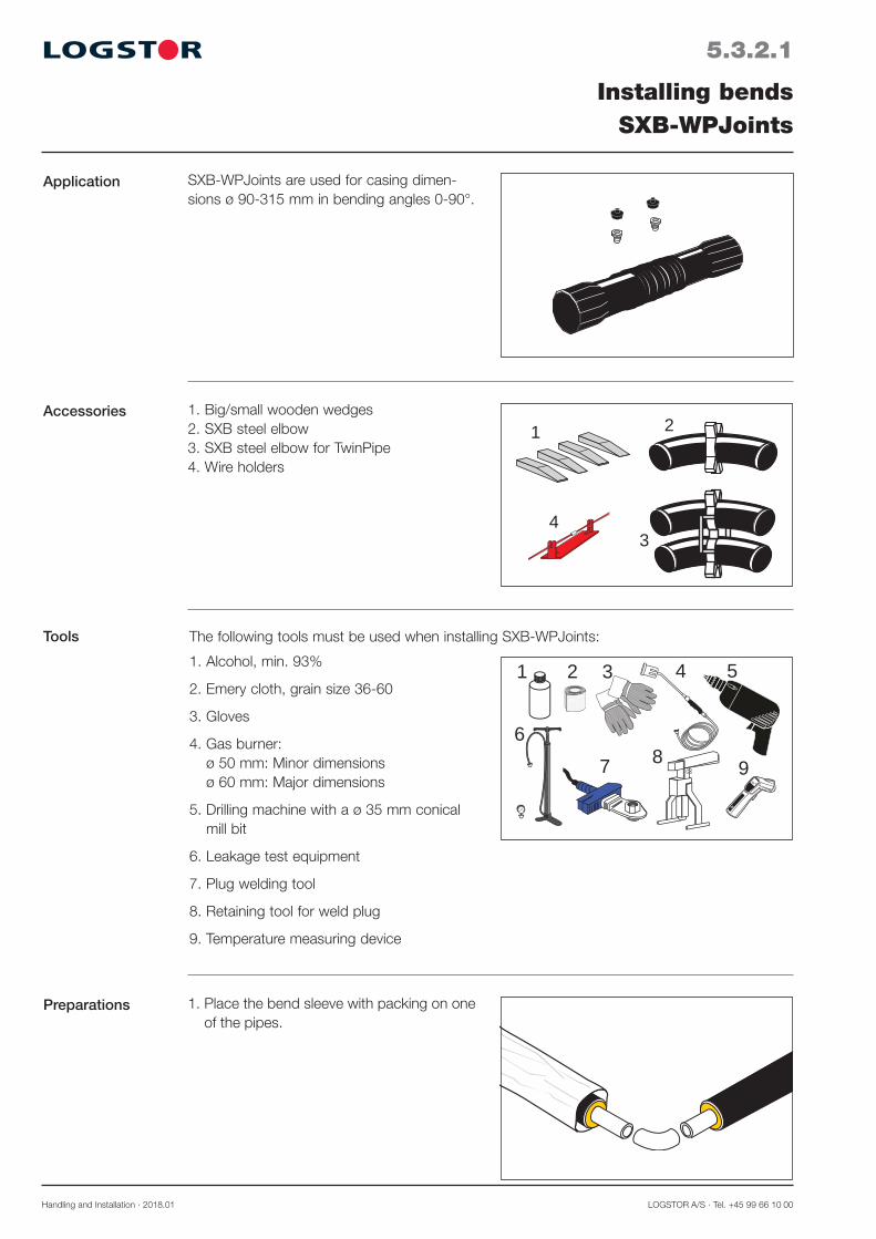
Handling and Installation · 2018.01 LOGSTOR A/S · Tel. +45 99 66 10 00
5.3.2.1
Application
Installing bendsSXB-WPJoints
SXB-WPJoints are used for casing dimen-sions ø 90-315 mm in bending angles 0-90°.
Accessories 1. Big/small wooden wedges 2. SXB steel elbow 3. SXB steel elbow for TwinPipe4. Wire holders
Tools
1. Place the bend sleeve with packing on one of the pipes.
Preparations
1 2
34
The following tools must be used when installing SXB-WPJoints:
1. Alcohol, min. 93%
2. Emery cloth, grain size 36-60
3. Gloves
4. Gas burner: ø 50 mm: Minor dimensions ø 60 mm: Major dimensions
5. Drilling machine with a ø 35 mm conical mill bit
6. Leakage test equipment
7. Plug welding tool
8. Retaining tool for weld plug
9. Temperature measuring device
1 2 54
6
3
87 9
65°

LOGSTOR A/S · Tel. +45 99 66 10 00 Handling and Installation · 2018.01
5.3.2.2
Weld elbow
Installing bendsSXB-WPJoints
4. Measure from the welds and mark the length L clearly on both casing pipes. L is found in the table for the relevant series on the last pages of this section.
Measure 115 mm back from the marking L and cut off insulation.
L 115
5. Place the spacer in the middle of the bend. The beveled edge must face the bend sleeve.
6. Place the wire retainers and the alarm wi-res as stated in section 23.4 ”Connecting alarm wires” Make sure the wires are not in contact with the service pipe.
2. Cut the steel elbow at the wanted angle and weld it in between the two pipe ends.
TwinPipe: It is important to mount the two steel elbows parallel to each other.
Important: Use only special steel elbow from LOGSTOR.
3. All surfaces must be CLEAN and DRY. Clean with alcohol.
Cleaning
Marking and adjustment
Alarm wires
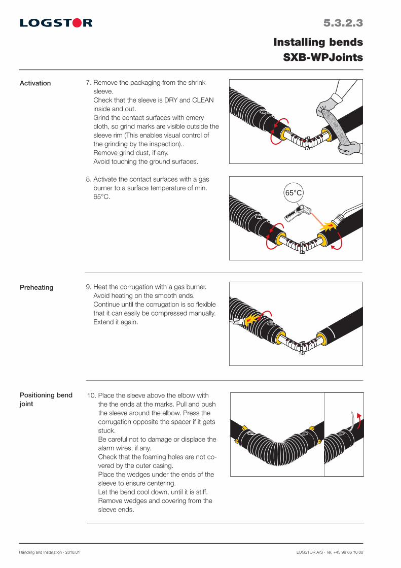
Handling and Installation · 2018.01 LOGSTOR A/S · Tel. +45 99 66 10 00
5.3.2.3
Preheating
Installing bendsSXB-WPJoints
10. Place the sleeve above the elbow with the the ends at the marks. Pull and push the sleeve around the elbow. Press the corrugation opposite the spacer if it gets stuck. Be careful not to damage or displace the alarm wires, if any. Check that the foaming holes are not co-vered by the outer casing. Place the wedges under the ends of the sleeve to ensure centering. Let the bend cool down, until it is stiff. Remove wedges and covering from the sleeve ends.
9. Heat the corrugation with a gas burner. Avoid heating on the smooth ends. Continue until the corrugation is so flexible that it can easily be compressed manually. Extend it again.
7. Remove the packaging from the shrink sleeve. Check that the sleeve is DRY and CLEAN inside and out. Grind the contact surfaces with emery cloth, so grind marks are visible outside the sleeve rim (This enables visual control of the grinding by the inspection).. Remove grind dust, if any. Avoid touching the ground surfaces.
Positioning bend joint
Activation
8. Activate the contact surfaces with a gas burner to a surface temperature of min. 65°C.
65°
65°C
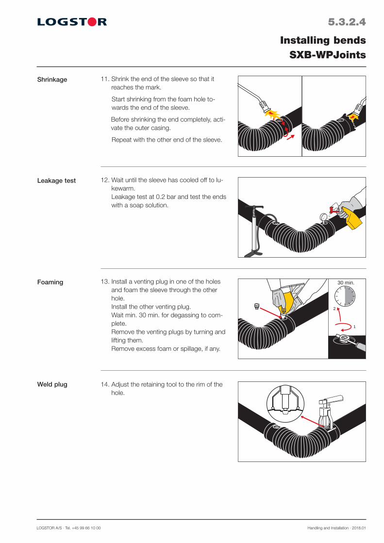
LOGSTOR A/S · Tel. +45 99 66 10 00 Handling and Installation · 2018.01
5.3.2.4
Leakage test
Installing bendsSXB-WPJoints
12. Wait until the sleeve has cooled off to lu-kewarm. Leakage test at 0.2 bar and test the ends with a soap solution.
13. Install a venting plug in one of the holes and foam the sleeve through the other hole. Install the other venting plug. Wait min. 30 min. for degassing to com-plete. Remove the venting plugs by turning and lifting them. Remove excess foam or spillage, if any.
1
2
30 min.Foaming
11. Shrink the end of the sleeve so that it reaches the mark.
Start shrinking from the foam hole to-wards the end of the sleeve.
Before shrinking the end completely, acti-vate the outer casing.
Repeat with the other end of the sleeve.
Shrinkage
Weld plug 14. Adjust the retaining tool to the rim of the hole.

Handling and Installation · 2018.01 LOGSTOR A/S · Tel. +45 99 66 10 00
5.3.2.5
Installing bendsSXB-WPJoints
Weld plug,continued
16. Heat the plug welder to 250°C ± 10°C.
17 . Place the weld plug in the conical hole of the plug welder and the opposite side of the tool in the foam hole, so the weld plug and the rim of the hole are heated at the same time.
1-2 mm
12
15. Drill the plug hole with a conical drill bit to clean the PE hole rim.
Clean the rim and the casing surface around the hole with alcohol.
Insert the weld plug in the retaining tool and clean with alcohol and .
18. Remove the plug welder just before the cone touches the hole, and immediately press the plug down into the hole, until it is flush with the upper rim.
Hold the pressure constant at least 1 minute, until the welding zone has cooled down to handwarm, before the retaining tool is removed. There has to be a visible bead.
Repeat the process with the other plug.
19. The joint is complete.Finished joint

LOGSTOR A/S · Tel. +45 99 66 10 00 Handling and Installation · 2018.01
5.3.2.6
Installing bendsSXB-WPJoints
Marking length L, series 1Marking length, Single pipeseries 1
Marking length L, series 2Marking length, Single pipe series 2
Casing pipeø out. mm
Bend angle
0° 15° 30° 45° 60° 75° 90°
90 430 410 390 370 350 330 310
110 445 425 405 385 365 345 325
125 445 425 405 385 360 335 310
140 445 420 395 370 345 330 310
160 445 420 395 370 345 330 310
200 480 455 430 405 390 370 360
225 485 460 430 400 385 370 350
250 485 460 430 400 385 370 360
315 610 565 520 470 435 400 360
Casing pipeø out. mm
Bend angle
0° 15° 30° 45° 60° 75° 90°
110 445 425 405 385 365 345 325
125 445 425 405 385 360 335 310
140 445 420 395 370 345 330 310
160 445 420 395 370 345 330 310
180 480 455 430 390 380 370 360
225 485 450 415 380 375 370 360
250 485 460 430 400 385 370 350
280 560 525 490 450 420 390 360
Marking length, Single pipe series 3
Marking length L, series 3
Outer casingø out. mm
Bend angle
0° 15° 30° 45° 60° 75° 90°
125 445 430 410 390 370 350 330
140 445 425 405 385 365 345 320
160 445 420 395 370 345 320 310
180 480 455 430 405 390 370 350
200 480 455 430 390 380 370 360
250 485 450 415 380 375 370 360
280 610 560 510 460 420 380 340
315 560 525 490 450 420 390 360
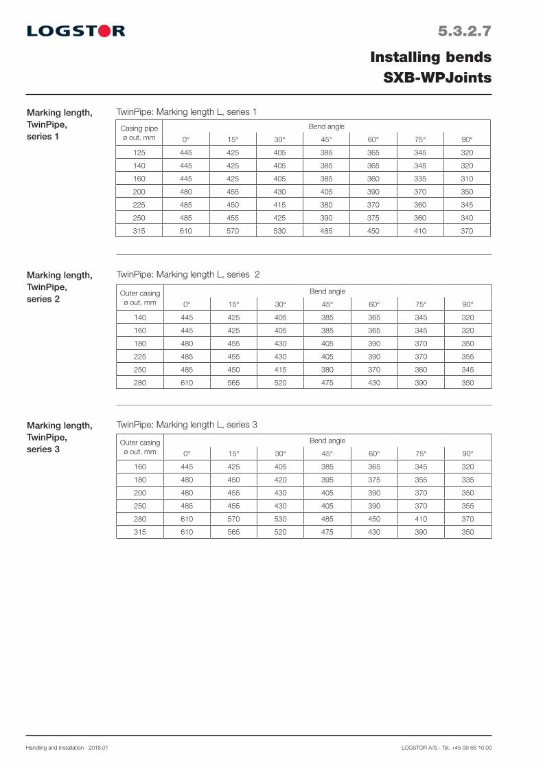
Handling and Installation · 2018.01 LOGSTOR A/S · Tel. +45 99 66 10 00
5.3.2.7
Installing bendsSXB-WPJoints
Marking length, TwinPipe, series 2
TwinPipe: Marking length L, series 2
TwinPipe: Marking length L, series 1Marking length, TwinPipe, series 1
Casing pipeø out. mm
Bend angle
0° 15° 30° 45° 60° 75° 90°
125 445 425 405 385 365 345 320
140 445 425 405 385 365 345 320
160 445 425 405 385 360 335 310
200 480 455 430 405 390 370 350
225 485 450 415 380 370 360 345
250 485 455 425 390 375 360 340
315 610 570 530 485 450 410 370
Marking length, TwinPipe, series 3
TwinPipe: Marking length L, series 3
Outer casing ø out. mm
Bend angle
0° 15° 30° 45° 60° 75° 90°
160 445 425 405 385 365 345 320
180 480 450 420 395 375 355 335
200 480 455 430 405 390 370 350
250 485 455 430 405 390 370 355
280 610 570 530 485 450 410 370
315 610 565 520 475 430 390 350
Outer casing ø out. mm
Bend angle
0° 15° 30° 45° 60° 75° 90°
140 445 425 405 385 365 345 320
160 445 425 405 385 365 345 320
180 480 455 430 405 390 370 350
225 485 455 430 405 390 370 355
250 485 450 415 380 370 360 345
280 610 565 520 475 430 390 350

LOGSTOR A/S · Tel. +45 99 66 10 00 Handling and Installation · 2018.01
5.3.3.1
Application
Installation instructions
Installing bendsPreinsulated bends
- Place the alarm wires in the upper part of the preinsulated bend.- When installing the bend vertically, note the alarm wire which has connection to the tinned
alarm wire in the straight preinsulated pipe (All wires in preinsulated bends are tinned).
Weld preinsulated bends like an ordinary preinsulated piece of pipe irrespective of angle.
Installation instructions for bends with differ-ent leg lengths
In bends with different leg lengths the alarm wires are placed in 3 and 9 o’clock position, so they may be turned upside down.
Bends with different leg lengths are used, when preinstallation of the joint on the bend is necessary. If so, the joint must be installed on the longer leg.


LOGSTOR A/S · Tel. +45 99 66 10 00 Handling and Installation · 2018.01
5.4.0.0
Introduction
Contents
Installing branch fittingsOverview
This section contains instructions for the installation of the branch joints and fittings which are included in standard pipe systems with PE outer casings.
Reinforcement plates 5.4.1
Shrink joints: SXTJoints 5.4.2 SXT-WPJoints 5.4.3
Weld joints: TSJoints 5.4.4 TS SaddleJoints 5.4.5 BandJoint branches 5.4.6 Installation equipment and requirements 5.4.7
Prefabricated branches 5.4.8 Branch from concrete duct 5.4.9


LOGSTOR A/S · Tel. +45 99 66 10 00 Handling and Installation · 2018.01
5.4.1.1
Application
Installing branch fittingsReinforcement plates
In connection with branch fittings it may be necessary to reinforce the main pipe when making cut outs for branches e.g. when the branch dimension is one or two dimensions smaller than the main pipe dimension.
This must appear from the design drawing, see the Design Manual.
In case of doubt please contact a LOGSTOR technician.
Description LOGSTOR supplies reinforcement plates, adjusted to relevant combinations of main pipe and branch pipe. See Product Catalogue, page 2.4.2.1.
The reinforcement plate is either one plate or - when the curvature of the plate exceeds the center line of the pipe - 2-part.
Welding on the reinforcement plate
The purpose of the reinforcement plate is to reinforce the main pipe.
The reinforcement plate must be fully welded to the main pipe and the branch.
The parts of a 2-part reinforcement plate must be welded together.
(A)
(A)
A/2
ø6
ød
ø6
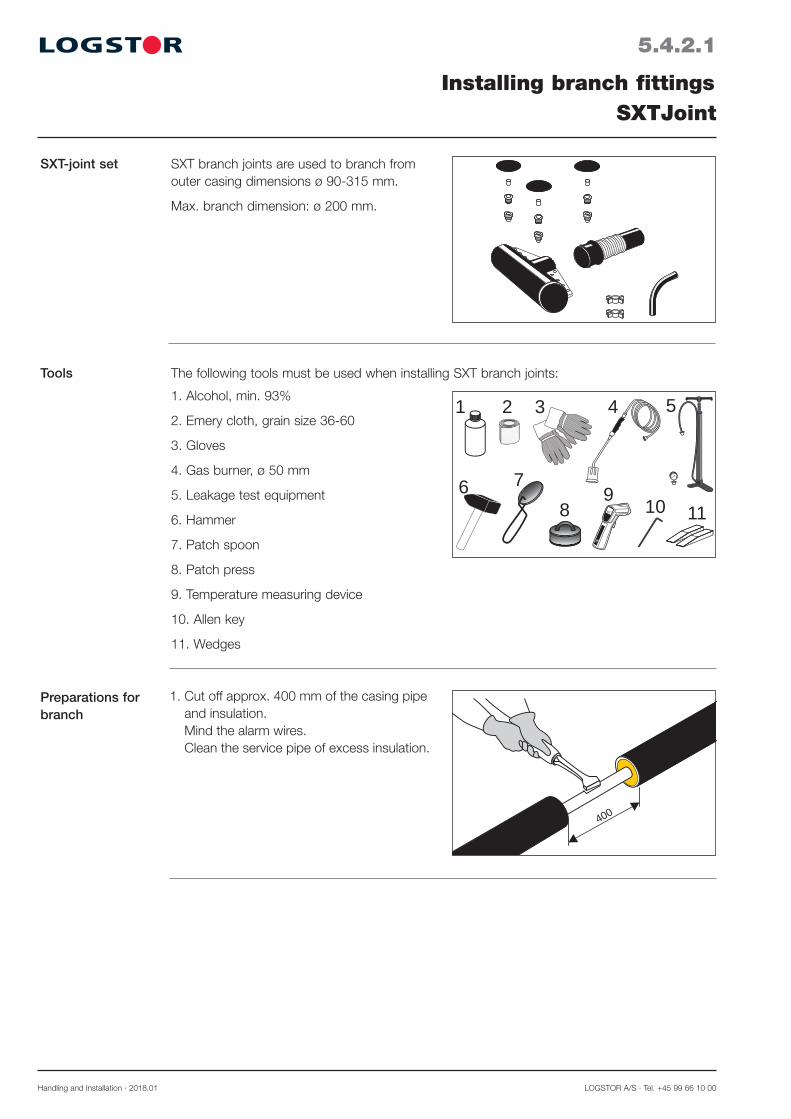
Handling and Installation · 2018.01 LOGSTOR A/S · Tel. +45 99 66 10 00
5.4.2.1
SXT-joint set
Installing branch fittingsSXTJoint
SXT branch joints are used to branch from outer casing dimensions ø 90-315 mm.
Max. branch dimension: ø 200 mm.
Tools
1. Cut off approx. 400 mm of the casing pipe and insulation. Mind the alarm wires. Clean the service pipe of excess insulation.
400
Preparations for branch
The following tools must be used when installing SXT branch joints:
1. Alcohol, min. 93%
2. Emery cloth, grain size 36-60
3. Gloves
4. Gas burner, ø 50 mm
5. Leakage test equipment
6. Hammer
7. Patch spoon
8. Patch press
9. Temperature measuring device
10. Allen key
11. Wedges
4 5
6
1 2 3
78 65°
9 10 11
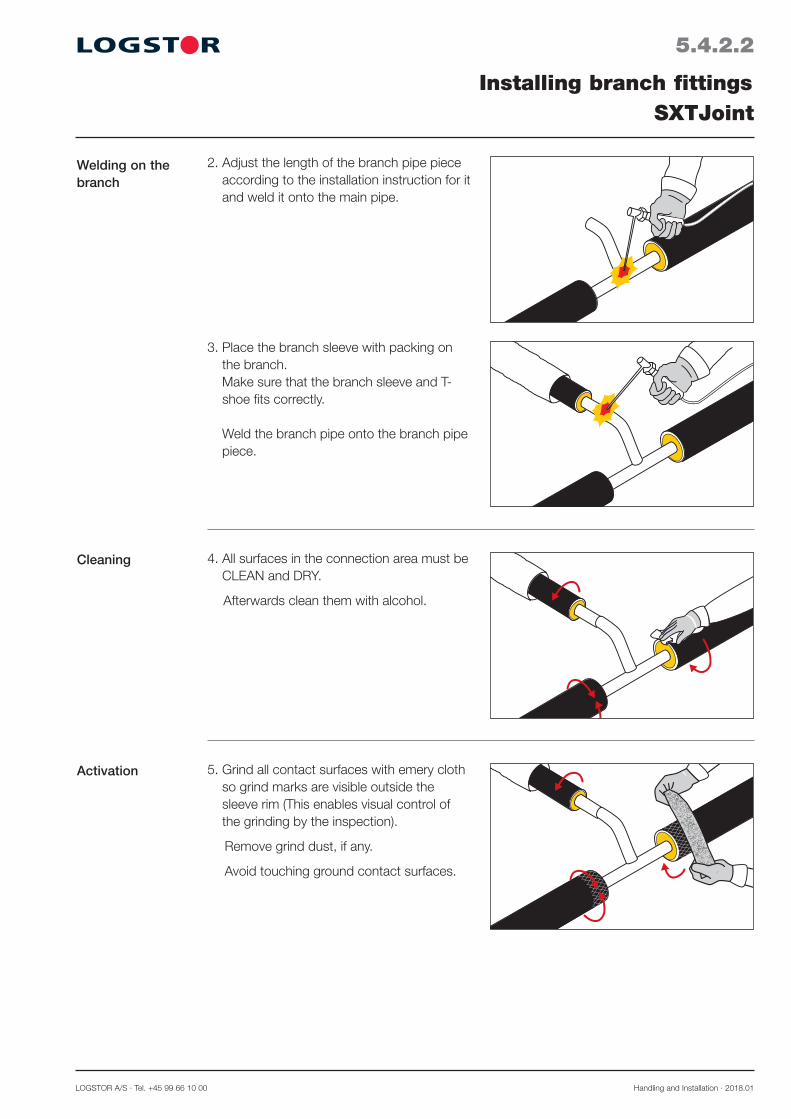
LOGSTOR A/S · Tel. +45 99 66 10 00 Handling and Installation · 2018.01
5.4.2.2
Welding on the branch
Installing branch fittingsSXTJoint
4. All surfaces in the connection area must be CLEAN and DRY.
Afterwards clean them with alcohol.
5. Grind all contact surfaces with emery cloth so grind marks are visible outside the sleeve rim (This enables visual control of the grinding by the inspection).
Remove grind dust, if any.
Avoid touching ground contact surfaces.
Cleaning
Activation
2. Adjust the length of the branch pipe piece according to the installation instruction for it and weld it onto the main pipe.
3. Place the branch sleeve with packing on the branch. Make sure that the branch sleeve and T-shoe fits correctly. Weld the branch pipe onto the branch pipe piece.

Handling and Installation · 2018.01 LOGSTOR A/S · Tel. +45 99 66 10 00
5.4.2.3
Activation, continued
Installing branch fittingsSXTJoint
L115
65°65°C
6. Activate all contact surfaces with a gas burner to a surface temperature of min. 65°C.
Installing T-shoe 8. Remove the packing from the T-shoe. Make sure that it is CLEAN and DRY inside.
Pull it over the main pipe. Turn the holes upside.
Centre the T-shoe in relation to the branch pipe piece and mark the position of the flanges on the outer casing.
7. Place a spacer in the middle of the bend and another in the middle of the straight run of the branch.
Mark the distance L from the welding onto the branch. see below table. To make foaming possible the free pipe ends generally have to be extended.
Measure 115 mm back from the marking L and cut off the insulation.
Preparing the branch
Marking length, series 1, 2, and 3
Main pipe ø mm
45° branch 90° branch
90 110 125 140 160 180 200 90 110 125 140 160 180 200
90 360 360
110 355 315 355 335
125 335 310 335 335 335 335
140 335 310 330 340 335 330 335 330
160 335 310 330 335 335 335 335 340
180 - 300 330 335 345 - 350 345 345 350
200 335 315 330 335 345 335 340 340 335 340
225 335 315 330 330 345 330 335 340 340 340 340 350
250 335 315 330 330 345 330 335 340 340 340 340 350
280 - 310 340 345 345 335 - - 350 345 345 350 340 -
315 335 320 335 335 345 - 330 335 340 340 340 340 - 350

LOGSTOR A/S · Tel. +45 99 66 10 00 Handling and Installation · 2018.01
5.4.2.4
Preparing the branch sleeve
Installing branch fittingsSXTJoint
10. Remove the packing from the branch sle-eve. Heat the corrugation at the top and bot-tom with a gas burner. Do not heat the smooth ends. Continue until the corrugation is so flexible that it can be compressed like a harmo-nica with the finger tips.
11. Remove the paper from the outer branch pipe piece. Remove the mastic cover from the inner T-shoe. Pull the branch sleeve over the branch pipe piece and insert the end in the opening of the T-shoe. The foam holes on the branch must turn upside Remove the two wooden wedges. Remove the internal flange cover and pull the two circumferential covers outside the joint ends. Place the ends of the branch sleeve exactly at the L-mark. Centre the sleeve with wedges. Place the T-shoe according to the mark on the outer casing. Mount the screws with washers and fa-sten the washers loosely with the fingers.
9. Insert 2 wooden wedges between the flan-ges over the mastic.
Installing T-shoe,continued

Handling and Installation · 2018.01 LOGSTOR A/S · Tel. +45 99 66 10 00
5.4.2.5
Leakage test
Installing branch fittingsSXTJoint
14. Leakage test at 0.2 bar. Check all joints with a soap solution. The solution must not get in contact with the plug areas.
15. Foam the sleeve via the T-shoe. Install the venting plugs in two of the ho-les and foam the sleeve through the third hole. Install the last venting plug. Wait min. 30 min. for degassing to com-plete. Remove the venting plugs by turning and lifting them. Remove excess foam or spillage, if any.
1
2
30 min.Foaming
12. Shrink the T-shoe by heating the ends, flanges and collar of the shoe. Note! Heat takes some time to penetrate plastic and steel/plastic and enter the ma-stic, which is to be softened. Heat slowly! Too hard a flame may result in no or slo-wer shrinkage. Heat the ends and collar in turn.
13. Remove the wedges and protective foil inside the branch sleeve. Shrink the outermost 100 mm of the sleeve. Wait until the sleeve has cooled down to handwarm. Tighten up the screws.
Shrinking the branch joint

LOGSTOR A/S · Tel. +45 99 66 10 00 Handling and Installation · 2018.01
5.4.2.6
Installing branch fittingsSXTJoint
18. Centre the wedge plugs in the expansion plugs and drive them into the plugs with a hammer until complete stop.
17. Mount the expansion plugs in the holes and press until the mastic is spread evenly under the collar of the plug.
1
1-2 sec.
2 Remove the protective foil from the expan-sion plugs and check the mastic. Activate briefly the recessed area with a hard flame.
Expansion plugs 16. Clean the whole surface of the recessed area around the holes with alcohol. Then grind the area with emery cloth. Remove grind dust, if any.

Handling and Installation · 2018.01 LOGSTOR A/S · Tel. +45 99 66 10 00
5.4.2.7
Installing branch fittingsSXTJoint
Finished joint 20. The joint is complete.
Patch installation 19. Place the patch on a patch spoon with the adhesive side facing up. Heat the adhesive side, until the adhesive agent is completely melted and begins to bubble/boil.
1-2sec.
20 sec.
Activate briefly the patch area with a hard flame. Place the patch over the plug with the ad-hesive side facing down. Heat the patch, until the green spots are no longer visible. Press it at once hard with the patch press for min. 20 sec. The patch must fit tightly to the area and the adhesive agent must be visible all around the patch. Repeat the process with the other two patches on top of the last two plugs.
NOTE! Do not touch the patch, before it has cooled.

LOGSTOR A/S · Tel. +45 99 66 10 00 Handling and Installation · 2018.01
5.4.3.1
Application
Installing branch fittingsSXT-WPJoint
SXT-WPJoints are used to branch from outer casing dimensions ø 90-315 mm.
Max. casing dimension of branch: ø 200 mm.
Tools
1. Cut off approx. 400 mm of the casing pipe and insulation. Mind the alarm wires.Clean the service pipe of excess insulation.
400
Preparations for branch
The following tools must be used when installing SXT-WPJoints:
1. Alcohol, min. 93%
2. Emery cloth, grain size 36-60
3. Gloves
4. Gas burner, ø 50 mm
5. Leakage test equipment
6. Drilling machine with a ø 35 mm conical mill bit
7. Plug welding tool
8. Retaining tool for weld plug
9. Temperature measuring device
10. Allen key
11. Wooden wedges
4 5
6
1 2 3
7 8 65°
9
10 11

Handling and Installation · 2018.01 LOGSTOR A/S · Tel. +45 99 66 10 00
5.4.3.2
Welding on the branch
Installing branch fittingsSXT-WPJoint
4. All surfaces in the connection area must be CLEAN and DRY.
Afterwards clean them with alcohol.
5. Grind all contact surfaces with emery cloth so grind marks are visible outside the sleeve rim (This enables visual control of the grinding by the inspection).
Remove grind dust, if any.
Avoid touching ground contact surfaces.
2. Adjust the length of the branch pipe piece according to the installation instruction for it and weld it onto the main pipe.
3. Place the branch sleeve with packing on the branch. Make sure that the branch sleeve and T-shoe fits correctly. Weld the branch pipe onto the branch pipe piece.
Cleaning
Activation

LOGSTOR A/S · Tel. +45 99 66 10 00 Handling and Installation · 2018.01
5.4.3.3
Activation, continued
Installing branch fittingsSXT-WPJoint
7. Place a spacer in the middle of the bend and another in the middle of the straight run of the branch.
Mark the distance L from the welding onto the branch. see below table. To make foaming possible the free pipe ends generally have to be extended.
Measure 115 mm back from the marking L and cut off the insulation.
L115
65°
65°C6. Activate all contact surfaces with a gas
burner to a surface temperature of min. 65°C.
Preparing the branch
Installing T-shoe 8. Remove the packing from the T-shoe. Make sure that it is CLEAN and DRY inside.
Pull it over the main pipe. Turn the holes upside.
Centre the T-shoe in relation to the branch pipe piece and mark the position of the flanges on the outer casing.
Marking length, series 1, 2, and 3
Main pipe ø mm
45° branch 90° branch
90 110 125 140 160 180 200 90 110 125 140 160 180 200
90 360 360
110 355 315 355 335
125 335 310 335 335 335 335
140 335 310 330 340 335 330 335 330
160 335 310 330 335 335 335 335 340
180 - 300 330 335 345 - 350 345 345 350
200 335 315 330 335 345 335 340 340 335 340
225 335 315 330 330 345 330 335 340 340 340 340 350
250 335 315 330 330 345 330 335 340 340 340 340 350
280 - 310 340 345 345 335 - - 350 345 345 350 340 -
315 335 320 335 335 345 - 330 335 340 340 340 340 - 350

Handling and Installation · 2018.01 LOGSTOR A/S · Tel. +45 99 66 10 00
5.4.3.4
Preparing the branch sleeve
Installing branch fittingsSXT-WPJoint
10. Remove the packing from the branch sle-eve. Heat the corrugation at the top and bot-tom with a gas burner. Do not heat the smooth ends. Continue until the corrugation is so flexible that it can be compressed like a harmo-nica with the finger tips.
11. Remove the paper from the outer branch pipe piece. Remove the mastic cover from the inner T-shoe. Pull the branch sleeve over the branch pipe piece and insert the end in the opening of the T-shoe. The foam holes on the branch must turn upside Remove the wooden wedges. Remove the internal flange cover and pull the two circumferential covers outside the joint ends. Place the ends of the branch sleeve exactly at the L-mark. Centre the sleeve with wedges. Place the T-shoe according to the mark on the outer casing. Mount the screws with washers and fa-sten the screws loosely with the fingers.
9. Insert 2 wooden wedges between the flan-ges over the mastic.
Installing T-shoe,continued
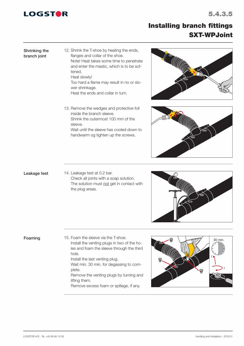
LOGSTOR A/S · Tel. +45 99 66 10 00 Handling and Installation · 2018.01
5.4.3.5
Leakage test
Installing branch fittingsSXT-WPJoint
14. Leakage test at 0.2 bar. Check all joints with a soap solution. The solution must not get in contact with the plug areas.
15. Foam the sleeve via the T-shoe. Install the venting plugs in two of the ho-les and foam the sleeve through the third hole. Install the last venting plug. Wait min. 30 min. for degassing to com-plete. Remove the venting plugs by turning and lifting them. Remove excess foam or spillage, if any.
1
2
30 min.Foaming
12. Shrink the T-shoe by heating the ends, flanges and collar of the shoe. Note! Heat takes some time to penetrate and enter the mastic, which is to be sof-tened. Heat slowly! Too hard a flame may result in no or slo-wer shrinkage. Heat the ends and collar in turn.
13. Remove the wedges and protective foil inside the branch sleeve. Shrink the outermost 100 mm of the sleeve. Wait until the sleeve has cooled down to handwarm og tighten up the screws.
Shrinking the branch joint

Handling and Installation · 2018.01 LOGSTOR A/S · Tel. +45 99 66 10 00
5.4.3.6
Installing branch fittingsSXT-WPJoint
Weld plug 16. Adjust the retaining tool to the upper rim of the hole.
18. Heat the plug welder to 250°C ± 10°C.
19 . Place the weld plug in the conical hole of the plug welder and the opposite side of the tool in the foam hole, so the weld plug and the rim of the hole are heated at the same time.
1-2 mm
1
2
17. Drill the plug hole with a conical drill bit to clean the PE hole rim.
Clean the rim and the casing surface around the hole with alcohol.
Insert the weld plug in the retaining tool and clean it with alcohol.
20. Remove the plug welder just before the cone touches the hole, and immediately press the plug down into the hole, until it is flush with the upper rim.
Hold the pressure constant at least 1 min-ute, until the welding zone is handwarm, before the retaining tool is removed. There has to be a visible bead.
Repeat the process with the other plugs in the remaining two holes.

LOGSTOR A/S · Tel. +45 99 66 10 00 Handling and Installation · 2018.01
5.4.3.7
Installing branch fittingsSXT-WPJoint
21. The joint is complete.Finished joint

Handling and Installation · 2018.01 LOGSTOR A/S · Tel. +45 99 66 10 00
5.4.4.1
Installing branch fittingsTSJoint
Application
Types
TSJoint is used to branch primarily to FlexPipes and FlextraPipes in dimensions ø 140 - 450 mm.
Branch dimensions: ø 90-125 mm.
It may be carried out as a 45° or 90° vertical branch or a 90° parallel branch.
The longitudinal opening at the main pipe is extrusion welded. The ends are sealed with mastic or EW weld-ing strips.
The branch has embedded mastic and is completed with a long shrink sleeve.
Adjusting branch pipe piece for TSJoint
x
T
L
ød
L
R
45°
ød
R
L
90°
A
A
A
X
T L
Each branch pipe piece is delivered long enough to fit SXT, TS and BandJoint branch in all three insulation series.
They are shortened prior to insulation in accordance with below instructions.
Shorten the straight part by marking two measurements: - “L” on the inside of the bend - T for the actual insulation thickness of the main pipe
(Possibly with the addition of “x” for adjustment of the main pipe).
ød,mm
20 R125 L mm
25 R125 L mm
23R160L mm
26,9 R140 L mm
33,7 R140 L mm
42,4 R140 L mm
48,3 R140L mm
60,3 R150 L mm
45° 320 320 320 320 320 320 320 350
90° 250 250 250 250 250 250 250 250
Shortening measurements for branch pipe piece

LOGSTOR A/S · Tel. +45 99 66 10 00 Handling and Installation · 2018.01
5.4.5.1
Installing branch fittingsTS SaddleJoint
Application
Types
Adjusting branch pipe piece for TS SaddleJoint
TS SaddleJoint is used to branch primarily to FlexPipes and FlextraPipes in main pipe dimen-sions ≥ 450 mm.
Branch dimensions: ø 90-125 mm.
It may be carried out as a 45° or 90° vertical branch or a 90° parallel branch.
The circumferential weld is carried out by means of extrusion welding.
The branch has embedded mastic and is completed with a long sleeve.
x
T
L
ød
L
R
45°
ød
R
L
90°
A
A
A
X
T L
Each branch pipe piece is delivered long enough to fit SXT, TS and BandJoint branch in all three insulation series.
They are shortened prior to insulation in accordance with below instructions.
Shorten the straight part by marking two measurements: - “L” on the inside of the bend - T for the actual insulation thickness of the main pipe
(Possibly with the addition of “x” for adjustment of the main pipe).
ød,mm
20 R125 L mm
25 R125 L mm
23R160L mm
26,9 R140 L mm
33,7 R140 L mm
42,4 R140 L mm
48,3 R140L mm
60,3 R150 L mm
45° 320 320 320 320 320 320 320 350
90° 250 250 250 250 250 250 250 250
Shortening measurements for branch pipe piece

Handling and Installation · 2018.01 LOGSTOR A/S · Tel. +45 99 66 10 00
5.4.6.1
Application
Distance between branching points
Placing parallel branch
Installing branch fittingsBandJoint branch
220 mm
150 mm
min. 1100 mm
220mm
min.400 mm
440 mm
90˚
45˚
90˚
The BandJoint branch is used is used to branch from main pipe ø 90-315 mm to:
- FlexPipes ø 90-140 mm - Straight pipes ø 90-140 mm
It can be carried out as 45° and 90° per-pendicular branches as well as 90° parallel branches.
Observe the shown distance measure-ments in order to ensure optimum space for the installation of the preinstalled branch BandJoint.
A mm: - øD ≤ 315 = 340
Place a 90° parallel branch in a 45° angle in relation to vertical.
Partly to ensure optimum positioning of the supporting depth guard, partly to ensure minimum height of the pipe system.
Branch pipes, flexible and straight pipes respectively.
Shortening measurements, branch pipes
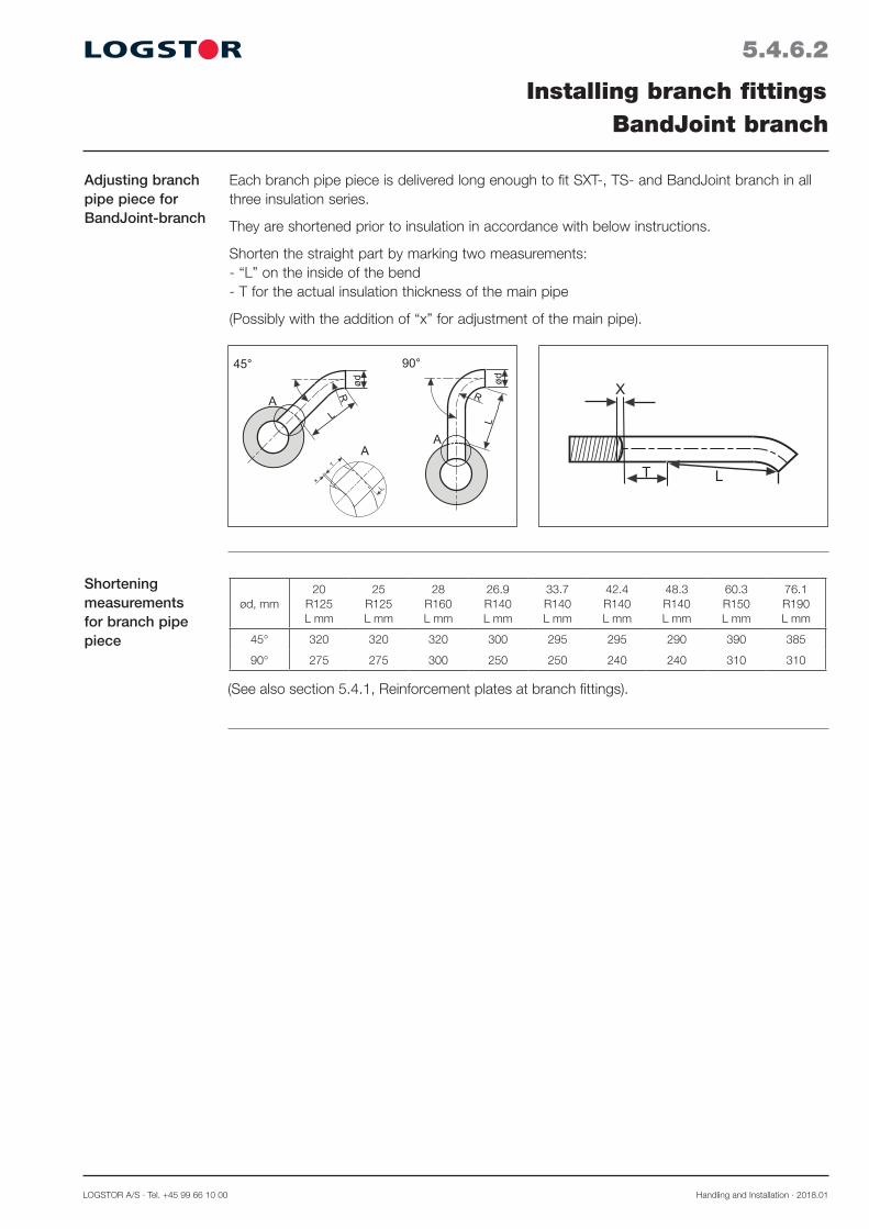
LOGSTOR A/S · Tel. +45 99 66 10 00 Handling and Installation · 2018.01
5.4.6.2
Installing branch fittingsBandJoint branch
Adjusting branch pipe piece for BandJoint-branch
x
T
L
ød
L
R
45°
ød
R
L
90°
A
A
A
X
T L
Each branch pipe piece is delivered long enough to fit SXT-, TS- and BandJoint branch in all three insulation series.
They are shortened prior to insulation in accordance with below instructions.
Shorten the straight part by marking two measurements: - “L” on the inside of the bend - T for the actual insulation thickness of the main pipe
(Possibly with the addition of “x” for adjustment of the main pipe).
ød, mm20
R125 L mm
25 R125 L mm
28 R160 L mm
26.9 R140 L mm
33.7 R140 L mm
42.4 R140 L mm
48.3 R140 L mm
60.3 R150 L mm
76.1 R190 L mm
45° 320 320 320 300 295 295 290 390 385
90° 275 275 300 250 250 240 240 310 310
(See also section 5.4.1, Reinforcement plates at branch fittings).
Shortening measurements for branch pipe piece
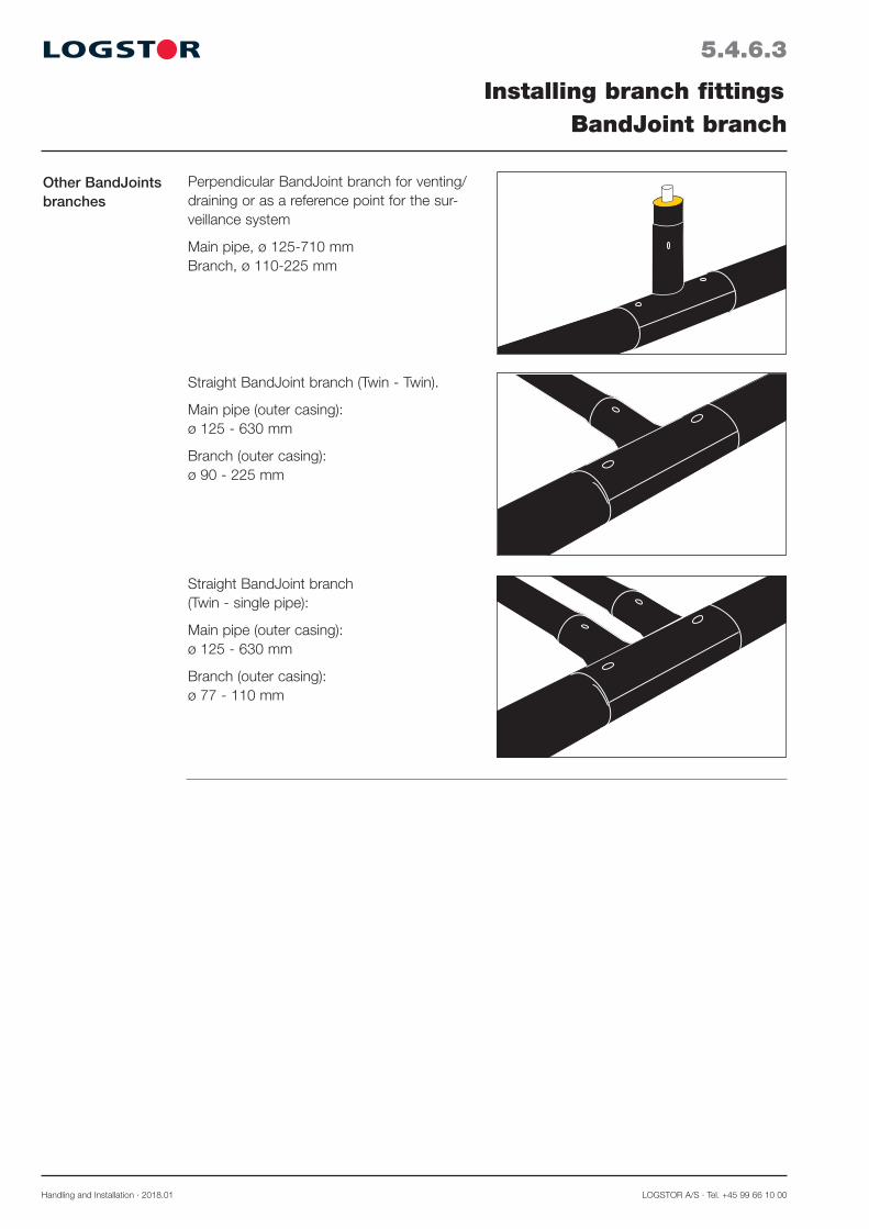
Handling and Installation · 2018.01 LOGSTOR A/S · Tel. +45 99 66 10 00
5.4.6.3
Installing branch fittingsBandJoint branch
Other BandJointsbranches
Perpendicular BandJoint branch for venting/draining or as a reference point for the sur-veillance system
Main pipe, ø 125-710 mm Branch, ø 110-225 mm
Straight BandJoint branch (Twin - Twin).
Main pipe (outer casing): ø 125 - 630 mm
Branch (outer casing): ø 90 - 225 mm
Straight BandJoint branch (Twin - single pipe):
Main pipe (outer casing): ø 125 - 630 mm
Branch (outer casing): ø 77 - 110 mm

LOGSTOR A/S · Tel. +45 99 66 10 00 Handling and Installation · 2018.01
5.4.7.1
Installing branch fittingsInstallation equipment and requirements for weld joints
Installation equip-ment
Control of the welding process
Use a LOGSTOR trailer containing generator, compressor, welding machine, straps and all necesssary tools for the installation work.
Carry out the welding process with a com-puter controlled welding machine which automatically controls the welding and checks that the welding temperature and the pressure between the welding surfaces are correct.
Fitters The installation is carried out by certified fitters who have been specially educated and trained at LOGSTOR. An education and training which are kept up by follow-up courses at least every second year.
Installation instructions
The certified fitters must use the authorized installation equipment and follow the instructions in the Weld Joint Manual, which can be ordered at LOGSTOR.

Handling and Installation · 2018.01 LOGSTOR A/S · Tel. +45 99 66 10 00
5.4.8.1
Application
Installation instructions
Installing branch fittingsPrefabricated branch
Use preinsulated T-pieces when the branch fittings systems cannot be used for dimen-sional limiting reasons.
Especially in connection with under-crossing branch pipes they are advantageous to use as there is no foaming problem.
Weld prefabricated branches like normal pre-fabricated pieces of pipe.
They are always delivered with 3 embed-ded alarm wires. The middle wire, i.e. the tinned one, has connection to the connecting branch.
The two through-going wires are blank copper wires.
Regarding connection of alarm wires, see the alarm drawing.

LOGSTOR A/S · Tel. +45 99 66 10 00 Handling and Installation · 2018.01
5.4.9.1
Application
Branch with outer casing dimensions ø 90-140 mm
Branch with outer casing dimensions > ø 140 mm
Installing branch fittingsBranching from concrete duct
750
M
1-2 min.
1. Make a hole in the concrete wall of approx. 750 mm where the branch will be established.
Prior to installation, the duct is extended.See section 10.2 Installing sealing ring as well as 10.3 Installing end-cap.
2. Pull the shrink sleeve and branch adaptor in over the branch pipe.
3. Adjust the height and length of the two branch pipes.
4. Shrink end-caps on. See section 10.3.1 Installation of end-cap
5. Weld the branch on to the main pipe6. Pull the branch adaptor into position flush
with the concrete wall.
It is very important to pay attention to the temperature conditions and the position of anchors to ensure that the branch can expand.
7. Pull the shrink sleeve over the end of the branch adaptor and shrink the sleeve.
Wait 1-2 minutes before shrinking on the outer casing.Now the installation is complete and the con-crete wall can be repaired.
When branches are made with pipes from a concrete duct, a branch adaptor is used to ensure a watertight entry into the duct and to allow the main pipe to expand with the branch.

Handling and Installation · 2018.01 LOGSTOR A/S · Tel. +45 99 66 10 00
5.4.9.2
Branching with FlexPipe
Installing branch fittingsBranching from concrete duct
1. Pull the shrink sleeve and the branch adaptor in over the branch pipe.
2. Adjust the 90° bend (200 x 300 mm) to fit horizontally and vertically in the installa-tion. Cut the bend at right angles using a hacksaw with small saw teeth.
3. Weld the adjusted bend and the welding stub together.
4. Weld the bend pipe on to the reduction piece. See section 12 FlexPipes.
5. Shrink the end-cap on the FlexPipe end. (See section 10.3 Installing end-cap).
6. Shrink the shrink tubing around the reduction piece and the free end of the FlexPipe.
7. Pull the shrink tubing on to the FlexPipe, while it is still warm.
8. Weld the branch on to the main pipe.
9. Pull the branch adaptor in position flush with the concrete wall.
It is very important to pay attention to the temperature conditions and the position of the anchors to ensure that the branch can expand.
10. Pull the shrink sleeve in over the branch adaptor end and shrink the sleeve.
Wait 1-2 minutes before shrinking the outer casing.The installation is now complete and the concrete wall can be repaired.
1-2 min.
LOGSTOR A/S · Tel. +45 99 66 10 00 Handling and Installation · 2009.11
6.0.0.1
Introduction
Contents
Hot tappingOverview
This section contains instructions for adjusting and installing hot tapping valves as well as carrying out hot tapping on district heating pipes in operation.
Adjusting and installing hot tapping valve, type 1 6.1.1Carrying out hot tapping with type 1 6.1.2
Adjusting and installing hot tapping valve, type 2 6.2.1Carrying out hot tapping with type 2 6.2.2


LOGSTOR A/S · Tel. +45 99 66 10 00 Handling and Installation · 2009.11
6.1.1.1
Hot tappingAdjusting and installing hot tapping valve, type 1
Application
Tools
Hot tapping valve, type 1, is used where branches in dimensions ø 26.9 -114.3 mm are made from main pipes in operation.
Type 1 is always used when branching to FlexPipes.
When installing hot tapping valve, type 1, use the following tools:Tools: Used for: Illustration:
7 6 5
2
14
3
Hacksaw or grinder Adjusting valve to main pipe
Hot tapping equipment Piercing main pipe
Electrical welding Welding on hotapparatus tapping valve
Adjusting welding ring and hot tap-ping valve
1. Remove the insulation and clean the sur-face of the main pipe carefully, before drill-ing and tapping.
2. Adjust the weld end of the hot tapping valve by means of a grinding machine to the rounding of the main pipe according to DIN 2559 Notch type 22. It is important that the valve is handled so grind particles or other foreign particles do not get into the valve.

Handling and Installation · 2009.11 LOGSTOR Fredericia A/S · Tel. +45 76 23 30 00
6.1.1.2
Hot tappingAdjusting and installing hot tapping valve, type 1
Checking the equipment
Before every drilling the main tool has to be inspected.
- Please make sure, that the drill/hole saw is in such a condition that the process can be car-ried through, otherwise the drill/hole saw has to be sharpened or renewed.
- Renew defective sealings and gaskets.- Tighten all screws, which hold the centre drill and the holesaw, very hard before every tap-
ping process.
Welding the hot tapping valve
3. The hot tapping valve can be welded on to the main pipe in angels that fit the actual branch.
4. During welding the valve must be in com-pletely open position!
5. The valve has to be welded on by means of electric arc welding, the thread facing outwards. It is very important that no welding mate-rial enters the valve and interferes with the drilling and the sawing.
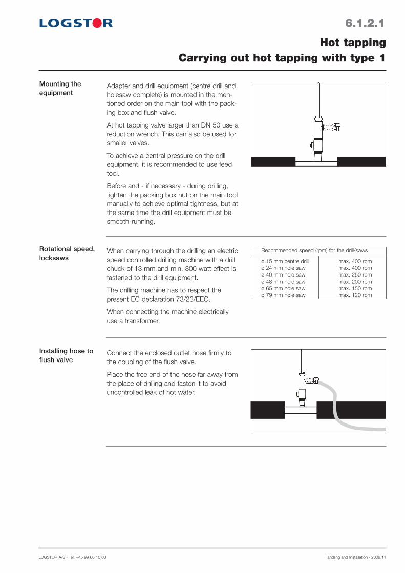
LOGSTOR A/S · Tel. +45 99 66 10 00 Handling and Installation · 2009.11
6.1.2.1
Hot tappingCarrying out hot tapping with type 1
Mounting the equipment
Adapter and drill equipment (centre drill and holesaw complete) is mounted in the men-tioned order on the main tool with the pack-ing box and flush valve.
At hot tapping valve larger than DN 50 use a reduction wrench. This can also be used for smaller valves.
To achieve a central pressure on the drill equipment, it is recommended to use feed tool.
Before and - if necessary - during drilling, tighten the packing box nut on the main tool manually to achieve optimal tightness, but at the same time the drill equipment must be smooth-running.
Rotational speed, locksaws
When carrying through the drilling an electric speed controlled drilling machine with a drill chuck of 13 mm and min. 800 watt effect is fastened to the drill equipment.
The drilling machine has to respect the present EC declaration 73/23/EEC.
When connecting the machine electrically use a transformer.
Recommended speed (rpm) for the drill/saws
ø 15 mm centre drill max. 400 rpm ø 24 mm hole saw max. 400 rpm ø 40 mm hole saw max. 250 rpm ø 48 mm hole saw max. 200 rpm ø 65 mm hole saw max. 150 rpm ø 79 mm hole saw max. 120 rpm
Installing hose to flush valve
Connect the enclosed outlet hose firmly to the coupling of the flush valve.
Place the free end of the hose far away from the place of drilling and fasten it to avoid uncontrolled leak of hot water.

Handling and Installation · 2009.11 LOGSTOR Fredericia A/S · Tel. +45 76 23 30 00
6.1.2.2
Hot tappingCarrying out hot tapping with type 1
Hot tapping 1. Before starting the process of drilling by means of the hole saw, check that the centre drill of the hole saw does not pre-vent the ball from closing.
2. Pull the drill equipment back to stop and then close the ball carefully. If the centre drill is projected too far into the passage of the valve, then the tool has to be dis-mounted and the centre drill has to be re-adjusted.
3. During drilling adjust the opening of the flush valve (depending on the pressure). Slow drilling at light feed gives small chips, which can be drained through the outlet hose. It is important that the hole saw is not pushed hard against the pipe, when the centre drill is entering the pipe.
4. When drilling it is important that a nec-essary differential pressure is achieved through optimal opening of the flush valve, at that moment, when the circular blank has been cut out. The pressure is neces-sary to keep the cut away circular blank up in the hole saw. Therefore do not enter the drill equipment further into the main pipe than necessary.
5. When the drill/holesaw is through the wall of the main pipe then pull the drill/holesaw carefully all the way back to stop. Then turn the ball of the hot tapping valve 90° to closed position by using a screwdriver/Allen key.
6. Make sure that water does not run from the hose. Since the ball in the hot tapping valve has no automatic stop, you may have to adjust the position of the ball until it is in correctly closed position.
7. Now the hot tapping tool is dismounted in opposite order and the connecting pipe can be welded on to the system.
8. Afterwards the valve can be opened and the conical screw mounted and tightened. To get a fully welded pipe system place a weld round the conical screw.

LOGSTOR A/S · Tel. +45 99 66 10 00 Handling and Installation · 2009.11
6.2.1.1
Application
Tools
Adjusting welding ring and hot tap-ping valve
Hot tappingAdjusting and installing hot tapping valve, type 2
Hot tapping valve, type 2, is used where branches in dimensions ø 33.7-114.3 mm are made from main pipes in operation.
A
1. Adjust the welding ring to suit the main pipe.
2. Check the A-measurement before weld-ing the welding ring and the hot tapping valve.
When installing hot tapping valve, type 2, use the following tools:Tools: Used for: Illustration:Hacksaw or grinder Welding ring and
hot tapping valve
Silicone oil Lubrication
Electrical welding Welding on hotapparatus tapping valve
Hot tapping equipment Piercing main pipe

Handling and Installation · 2009.11 LOGSTOR Fredericia A/S · Tel. +45 76 23 30 00
A-measurement for Series 1 pipes
A-measurements for Series 2 pipes
Branch pipe ø mm: Main pipe ø mm 33,7/90 42,4/100 48,3/110 60,3/125 76,1/140 88,9/160 114,3/200
Branch pipe ø mm: Main pipe ø mm: 33,7/110 42,4/125 48,3/125 60,3/140 76,1/160 88,9/180 114,3/225
6.2.1.2
Hot tappingAdjusting and installing hot tapping valve, type 2
48,3/110 143 60,3/125 133 156 76,1/140 132 142 140 88,9/160 133 149 137 139 114,3/200 127 147 133 140 150 139,7/225 126 149 136 135 142 128 171 168,3/250 132 147 137 137 144 131 173 219,1/315 129 144 134 134 148 131 175 273/400 104 124 114 114 134 118 147 323,9/450 104 124 114 119 135 113 150 355,6/500 105 125 115 110 136 115 157 406,4/520 106 121 121 116 136 122 159 457/560 106 126 116 116 136 122 155 508/630 109 124 114 119 139 119 153 559/710 109 124 114 114 134 119 154 610/780 104 124 114 114 129 119 149
48,3/125 131 60,3/140 130 148 76,1/160 132 152 140 88,9/180 130 150 140 140 114,3/225 134 149 140 142 147 139,7/250 132 147 142 141 148 129 177 168,3/280 130 150 140 140 150 130 180 219,1/355 129 127 117 118 127 104 153 273/450 107 129 119 119 134 118 153 323,9/500 109 129 119 119 135 119 155 355,6/520 109 125 115 115 136 120 152 406,4/560 105 125 120 115 135 126 153 457/630 105 129 119 119 134 122 153 508/710 109 124 119 119 134 119 153 559/780 104 124 119 119 134 114 154
Deviating A-measurement 3)1)
2)
max
.10
mm
min
.10
mm
max
. 10
mm
m
ax. 1
0 m
m If the A-measurement is shorter than the
measurement, stated in the table for Series 1 or Series 2 pipes, weld a pipe piece between the weld elbow and the hot tapping valve in a length, corresponding to the miss-ing mm.If the A-measurement is longer than stated there are two possibilities:1. Shorten welding ring2 + 3. Shorten hot tapping valve
Note! First shorten at item 3 after hot tap-ping has been carried out (see Final installa-tion).
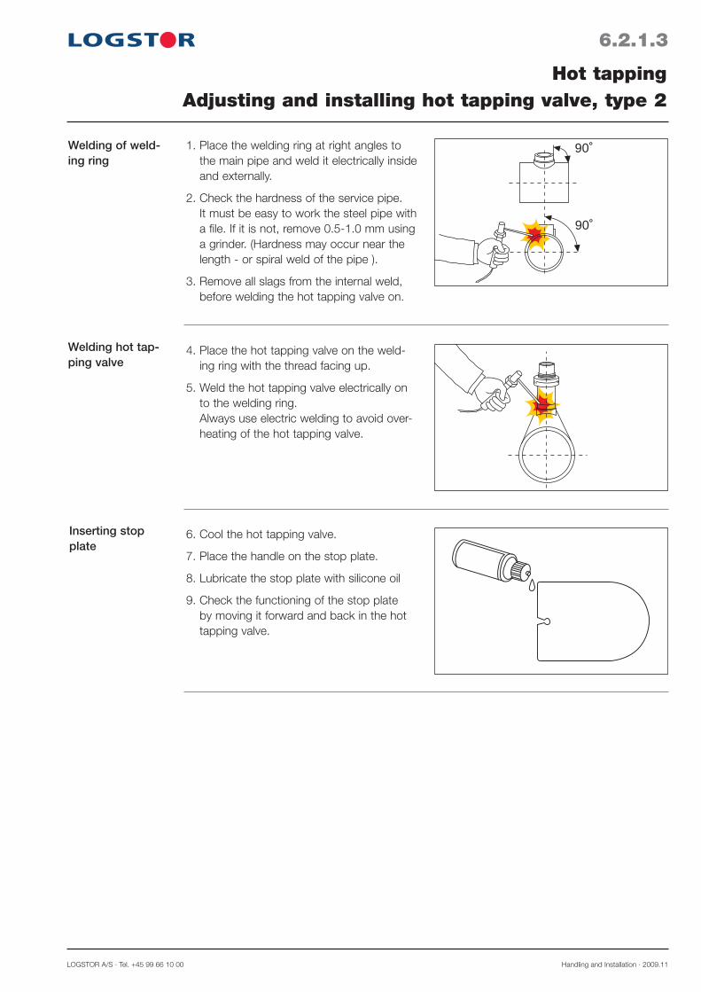
LOGSTOR A/S · Tel. +45 99 66 10 00 Handling and Installation · 2009.11
6.2.1.3
Welding of weld-ing ring
Welding hot tap-ping valve
Inserting stop plate
Hot tappingAdjusting and installing hot tapping valve, type 2
90˚
90˚1. Place the welding ring at right angles to the main pipe and weld it electrically inside and externally.
2. Check the hardness of the service pipe. It must be easy to work the steel pipe with a file. If it is not, remove 0.5-1.0 mm using a grinder. (Hardness may occur near the length - or spiral weld of the pipe ).
3. Remove all slags from the internal weld, before welding the hot tapping valve on.
4. Place the hot tapping valve on the weld-ing ring with the thread facing up.
5. Weld the hot tapping valve electrically on to the welding ring. Always use electric welding to avoid over-heating of the hot tapping valve.
6. Cool the hot tapping valve.
7. Place the handle on the stop plate.
8. Lubricate the stop plate with silicone oil
9. Check the functioning of the stop plate by moving it forward and back in the hot tapping valve.
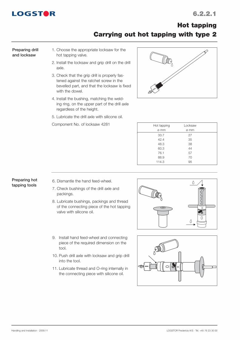
Handling and Installation · 2009.11 LOGSTOR Fredericia A/S · Tel. +45 76 23 30 00
Preparing hot tapping tools
6. Dismantle the hand feed-wheel.
7. Check bushings of the drill axle and packings.
8. Lubricate bushings, packings and thread of the connecting piece of the hot tapping valve with silicone oil.
9. Install hand feed-wheel and connecting piece of the required dimension on the tool.
10. Push drill axle with locksaw and grip drill into the tool.
11. Lubricate thread and O-ring internally in the connecting piece with silicone oil.
6.2.2.1
Preparing drill and locksaw
Hot tappingCarrying out hot tapping with type 2
1. Choose the appropriate locksaw for the hot tapping valve.
2. Install the locksaw and grip drill on the drill axle.
3. Check that the grip drill is properly fas-tened against the ratchet screw in the bevelled part, and that the locksaw is fixed with the dowel.
4. Install the bushing, matching the weld-ing ring, on the upper part of the drill axle regardless of the height.
5. Lubricate the drill axle with silicone oil.
Component No. of locksaw 4281 Hot tapping Locksaw ø mm ø mm
33.7 27 42.4 35 48.3 38 60.3 44 76.1 57 88.9 70 114.3 95

LOGSTOR A/S · Tel. +45 99 66 10 00 Handling and Installation · 2009.11
6.2.2.2
Installing hot tapping valve
Hot tappingCarrying out hot tapping with type 2
Rotational speed, locksaws
1
2
3
Hot tapping valve Locksaw Drilling machine ø mm ø mm r.p.m
12. Install the tool on the thread of the hot tapping valve and screw it fully home, achieving a sealing between the tool and the valve through the O-ring against the bare pipe piece.
13. Carefully lower the drill axle until the grip drill touches the steel pipe.
14. Pressure test the welds through the check valve (1).
15. Turn the hand feed-wheel (2) to its utter-most position.
16. Fix the adjusting/fixing screws in the most appropriate track (3).
17. Tighten the hand feed-wheel until the grip drill touches the steel pipe.
18. Install the drilling machine with gear on the drill axle and fasten it with a M8 bolt through the gear shaft.
The rotational speed of drilling machines for the individual locksaws.
Rotational speed of the grip drill: 2400 r.p.m. 33.7 27 1450-1650 42.4 35 1250-1450 48.3 38 1100-1250 60.3 44 900-1050 76.1 57 750-900 88.9 70 650-800 114.3 95 600-750

Handling and Installation · 2009.11 LOGSTOR Fredericia A/S · Tel. +45 76 23 30 00
6.2.2.3
Hot tapping
Dismantling drill-ing machine
Hot tappingCarrying out hot tapping with type 2
(1)
(2)
Hot tapping must be carried out according to the valid instructions.
After hot tapping the installation must be under pressure to obtain the necessary seal-ing.
1. Loosely tighten the hand feed-wheel (1), so that the grip drill gets a hold and drills through the pipe wall. Use the drilling machine at the highest speed. Stop the drilling machine when the drill is through the pipe wall.
2. Carefully open the venting valve (2) and check that the drill is through.
3. Ventilate until the tool is filled with water. The water helps cooling during the subse-quent hot tapping. Slow tightening is recommended.
4. Turn the hand feed-wheel to its uttermost position. Move the adjusting/fixing screws down towards the pipe and fix them in the most appropriate position.
Important! Do not lift the axle during adjust-ment, as the grip drill may be damaged.
5. Choose the speed of the locksaw and start drilling with a slight tightening of the hand feed-wheel (1).
Never fix the drilling machine for permanent run, as the locksaw may seize and the drilling machine be torn out of the hand.
6. Dismantle drilling machine with gear from drill axle, when the hole has been drilled and the pipe piece is firmly fixed in the grip drill.
7. Loosen the adjusting/fixing screws and pull them downwards, making it possible to check whether the hole is clear or not.
8. Carefully lift the adjusting/fixing screws and dismantle them. The pressure in the pipe may cause the axle to be lifted to stop.

LOGSTOR A/S · Tel. +45 99 66 10 00 Handling and Installation · 2009.11
Inserting stop plate
Dismantling of tool
12. Dismantle the hot tapping tool and put it in the transport box. Important when dismantling locksaw and grip drill: The steel plate from the pipe wall should only be removed from the drill by dismantling the drill from the drill head and push the plate out opposite the grips. The locksaw cannot be dismantled before the drill head has been loosened and the ratchet screws are clear of the locksaw.
Do not use pipe tongs on the drill axle when dismantling the drill head.Use the tools supplied for dismantling.
If an axle extension has been used, it must be loosened by means of the piercing plug and key which are part of the hot tapping tools.
9. Pull the drill axle up into the tool and insert the stop plate in the hot tapping valve.
10. Dismantle the handle on the stop plate.
11. Open the check valve and check the tightness.
6.2.2.4
Hot tappingCarrying out hot tapping with type 2

Handling and Installation · 2009.11 LOGSTOR Fredericia A/S · Tel. +45 76 23 30 00
6.2.2.5
Final installation
Hot tappingCarrying out hot tapping with type 2
1. Check the A-measurement (See page 6.1.3). In case shortening is necessary, only use a hacksaw or grinder, never a cutting torch. Place a wet cloth in the hot tapping valve in order to protect the stop plate against sparks from the grinder.
2. Place a wet cloth around the hot tapping valve and weld the branch pipe on.
3. Pressure test the stop plate.
After installation pull the stop plate 1/4" out, making it possible to fill the branch without pressure shocks.If leakage appears at the sealing slot, stop it by moving the stop plate forth and back until 100% tightness has been obtained. Tightness is best obtained with pressure in the pipeline. It is possible that leakage will appear, if the pressure in the pipeline is lowered during drilling. The leakage will then disappear, when the pressure is increased.
4. Adjust the supplied basic rod and place it at the bottom of the welding area to pro-tect the packing.
5. Weld the packing slot. For further protection of the packing the welding should be carried out 3-4 times at some minutes' interval.
6. Complete the installation with branch fittings and insulation. See section 5.4 Installing branch fittings.

LOGSTOR A/S · Tel. +45 99 66 10 00 Handling and Installation · 2010.01
7.0.0.1
Introduction
Contents
Insulating jointsOverview
Joints in the pipe systems are primarily insulated with our foam packs. It is an easy-to-apply method according to which a two-component foam liquid, after mixing and filling, forms an effective insulation with the same properties as in the rest of the pipe system.Other insulation methods may be a possibility in special cases.
Foam packsGeneral 7.1Material safety data sheet 7.2Storage and handling 7.3Use of foam packs for SteelJoints 7.4Use of foam packs for joints with welding plugs 7.5Use of foam packs for shrink joints with patches 7.6Use of foam packs for foaming in alu wrap 7.7 Alternative foam pack combinations 7.8
Tables with foam pack numbers - Single pipes 7.9 - TwinPipes 7.10 - Copper pipe system 7.11 - Alu wrap 7.12
Other insulation methods Insulation shells 7.13Can foam 7.14Machine foam 7.15


LOGSTOR A/S · Tel. +45 99 66 10 00 Handling and Installation · 2010.01
7.1.0.1
Application
Description
Insulating jointsGeneral - Foam pack
Joints in the pipe systems are primarily insulated with our foam packs.
It is an easy-to-apply method according to which a two-component foam liquid, after mixing and filling, forms an effective insulation with the same properties as in the rest of the pipe system.
Foam packs which are stored in accordance with stated rules have a time limit for use of 12 months, counting from the stated production week.
Foam packs are supplied in pre-dosed pack-ings whose foam liquid quantity and ratio of mixture are controlled by the automatic filling process in the factory.
The numbering on the foam pack cartons corresponds to the numbering on/at each joint type.
However, as each joint type has many appli-cation possibilities, only the most common joint types are provided with numbering, so it must be ensured that the joint corresponds to the actual application.
Otherwise the table numbers in this manual section must be used..
Each carton is marked with installation instructions, information about contents and storage as well as safety data.
The carton contains a multi-ply plastic bag, divided into two sections which are sepa-rated by a clip bairrier.The brown liquid (A) (isocyanate) is in a completely diffusion-tight section, in which aluminium foil forms part of the construction of the bag.
The clear liquid (B) (polyole) is in a trans-parent section which makes it possible visually to control that the mixing of the liquids has been carried out correctly.
Also see the safety instructions on the carton.
0700000000815 4809
5
5
BA

Handling and Installation · 2010.01 LOGSTOR Fredericia A/S · Tel. +45 76 23 30 00
7.1.0.2
Insulating jointsGeneral - Foam pack
Foam pack carton
Symbol of cartonrecycling
Smoking not allowed, whenworking with polyurethaneliquids
Temperature curves ofthe limited time for use
Instructions formixing and fillingtime
Description of health riskplus safety and first aid measures in differentlanguages No. of foam pack
size
Directionsfor use
Opening the foampack carton. Pullin accordance with the directionindicators
Product decla-ration in differentlanguages
Production week/production year
Part no.
LOGSTOR Fredericia A/STreldevej 191 DK-7000 Fredericia Phone + 45 76 23 30 00
t°C
10 1
525 3
0
30 2
520 1
5
70 6
0 5
0 4
5 4
0
20
20
sec.
sec.
3495
5
123
0700
000
0008
105
480
9 5
Phone +48 32 37 38 100 Emergency Phone +45 99 66 10 00 LOGSTOR Polska Sp. Z.o.o ul. Handlowa 1, PL-41-807 Zabrze
Emballagen åbnes først ved brug - Opbevar etiketten til produktet er opbrugt.Do not open the packaging before use - Keep the label until the product has been used up.
aufbewahren bis das Produkt aufgebraucht ist.Nie otwierac opakowania przed uzyciem. Zachowac etykiete do zuzycia produktu.
Die Verpackung nicht vor Anvendung öffnen - Das Etikett
Phone +48 32 37 38 100 Emergency Phone +45 99 66 10 00 LOGSTOR Polska Sp. Z.o.o ul. Handlowa 1, PL-41-807 Zabrze
Transportcode UN 1866
Description,continued
The clip barrier is removed by pulling at both sides of the bag and then the liquids mingle. The liquids are mixed by shaking the bag thoroughly at the same time as the built-in mixing stick is used for stirring.
Note! Each country poses its specific requirements to education/training and use of personal protective equipment for working with polyurethane foam. The customer or his representative is responsible for the compliance with these requirements.

LOGSTOR A/S · Tel. +45 99 66 10 00 Handling and Installation · 2010.01
7.2.0.1
Background
Material safety data sheet
Insulating jointsMaterial safety data sheet for foam pack
It is a requirement in all EU countries that material safety data sheets are issued when using hazard classified products.
Consequently, a material safety data sheet is an integrated part of the product “foam pack”.
It must always be at the user's disposal and may follow material deliveries or be forwarded separately by mail, fax and via data network.
Example The material safety data sheet contains 16 items of information SAFETY DATA SHEET
Product name FOAM PACK Version no.: 1 Page 5/5Created: 10-01-2008 Date of revision: 10-01-2008 Date of printing: 10-01-2008
Uses and Restrictions:Individuals wit more susceptibility to dermatitis should not be selected to work isocyanates.Not to be handled by persons under the age of 18 years.
Special Education:The user of the product must be thoroughly instructed in working with the product, the dangerous properties of the product and the necessary safety measurements.
OTHER INFORMATION:
R phrases:R11 Highly flammable.R20 Harmful by inhalation.R52 Harmful to aquatic organisms.R53 May cause long-term adverse effects in the aquatic environment.R36/37/38 Irritating to eyes, respiratory system and skin.R42/43 May cause sensitisation by inhalation and skin contact.
Final remarks:This safety data sheet is compiled on the basis of information from the supplier and in accordance with EU legislation. The users working conditions is outside our knowledge and control, we draw to your attention that it's always the users responsibility to take the necessary precautions and follow the given legislation.
References:CHIP3: Chemicals (Hazard Information and Packaging for Supply), Regulations 2002 (SI 2002/1689) and accompanying documentation. EH40/2005 Occupational Exposure Limits. COSHH : The Control of Substances Hazardous to Health Regulations 2992 and subsequent amendments. EC Regulation no. 1907/2006. REACH.HSE INDG388 10/03 C650 (Working with 2-pack isocyanate paints).
Drawn up by: pbb trotters apsQA ah 01-2008Updated by: pbb
16.
SAFETY DATA SHEETProduct name FOAM PACK Version no.: 1 Page 4/5Created: 10-01-2008 Date of revision: 10-01-2008 Date of printing: 10-01-2008
Accumulation:Not Known.
General information:Prevent material from entering drains, streams, lakes etc.
DISPOSAL CONSIDERATIONS:
Disposal considerations:Delivered to disposable centre according to the local regulations.
Waste code: 07 02 13 waste plastic08 05 01 waste isocyanates
General information:EAK 07 02 13 should be use when it is in a mixture or the waste from tiding up in section 6.
TRANSPORT INFORMATION:
ADR/RID UN no. 1866Class: 3Packaging group: IIHazard Identification: 33Proper Shipping Name: RESIN SOLUTION
IMDG-CODE UN no. 1866Class: 3Packaging group: IIEmS: F-E, S-EProper Shipping Name: RESIN SOLUTION
IATA UN no. 1866Class: 3Packaging group: IIProper Shipping Name: RESIN SOLUTION
General information:This Transport information is only relevant for Polyol (component B). Isocyanate (component A) is not comprised by transport regulations of dangerous goods.
REGULATORY INFORMATION:
Special labelling:Contains isocyanates.
Contains: Isocyanate (component A): Diphenylmethane-4,4´-diisocyanate, isomers and homologuePolyol (component B): Polyol with contains of cyclopentane
Labelling: Isocyanat (component A): Diphenylmethane-4,4´-diisocyanate, isomers and homologue
R20 Harmful by inhalation.R36/37/38 Irritating to eyes, respiratory system and skin.R42/43 May cause sensitisation by inhalation and skin contact.S23 Do not breathe vapour/spray.
S45 In case of accident or if you feel unwell, seek medical advice immediately (show the label where possible).
Xn
HarmfulS36/37 Wear suitable protective clothing and gloves.
Polyol (component B):R11 Highly flammable.
S9 Keep container in a well-ventilated place.S16 Keep away from sources of ignition - No smoking.
F
Highly flammable
S33 Take precautionary measures against static discharges.
14.
13.
15.
SAFETY DATA SHEETProduct name FOAM PACK Version no.: 1 Page 3/5Created: 10-01-2008 Date of revision: 10-01-2008 Date of printing: 10-01-2008
PHYSICAL AND CHEMICAL PROPERTIES:Isocyanate (component A) Polyol (component B)
Form: Liquid Liquid
Colour: Brown Clear, yellowing
Odour: Weak Weak
Density: 1,23 g/cm³ 1,04 g/cm³
Explosion limits: - 1,1-8,7 % (Cyclo pentane)
Boiling point: - > 48°C (Cyclo pentane)
Flash point: > 200°C 8°C
Melting point < 0°C <-10° C
Ignition temperature: > 400°C 380° C (Cyclo pentane)
Vapour pressure 1 hPa (20°C) 345 hPa (20°C) (Cyclo pentane)
Viscosity: 200 mPa (20°C) 690 mPa (23°C)
Water solubility: No No
STABILITY AND REACTIVITY:
Stability:Isocyanate (component A): Polymerisation occurs by 200°C. The polymerisation will develop CO2.Polyol (component B): The product is s table if it is handled and stored according to section 7.
Conditions to avoid:Temperature above 40°C.
Substances to avoid:Oxidizing agents and acids. Bases. Alcohols. Amines. Isocyanate (component A): Isocyanates reacts strongly with water under a heating development.
Hazardous Decomposition Products:When heated to high temperatures, or in case of fire, the product can liberate toxic gases/vapours of: Carbon oxides, nitrogen oxides, isocyanate, compound of cyanides.
Hardening time for Isocyanates.5 minutes at 20°C
TOXICOLOGICAL INFORMATION:
Inhalation:Isocyanate (component A): May irritate respiratory tract and may cause coughing, asthmatic breathing and difficulty in breathing. Polyol (component B): Vapours may cause bluntness and dizziness.
Contact with skin:Irritating to skin.
Contact with eyes:Irritating to eyes.
Ingestion:Ingestion may cause nausea and queasy.
Chronic effects:Isocyanate (component A): May cause sensitisation by inhalation and skin contact. Polyol (component B) Inhalation of vapours may cause drowsiness, dizziness and can cause damage to the central nervous system by prolounged exposure.
ECOLOGICAL INFORMATION:
Eco toxicity:None known.
Mobility:Isocyanate (componenet A), Polyol (componenet B) and the mixture are not soluble in water. Therefore there is no mobility in water.
Degradability:Isocyanate (component A): Bio-degradation: Difficult.Polyol (component B): Bio-degradation: Difficult.
9.
10.
11.
12.
SAFETY DATA SHEETProduct name FOAM PACK Version no.: 1 Page 2/5Created: 10-01-2008 Date of revision: 10-01-2008 Date of printing: 10-01-2008
Special protective equipment:Wear self-contained breathing apparatus and full protective gear when extinguishing fire.
General information:If it is without risk containers should be removed from the area where there is a risk of f ire.
6. ACCIDENTAL RELEASE MEASURES:Personal precautions:Remove all ignition sources and ensure sufficient ventilation. Avoid inhalation of vapours/aerosols and contact with skin and eyes. Unauthorized persons are forbidden to enter. Regarding personal protection - see section 8.
Prevent material from entering drains, streams, lakes etc.Environmental precautions:
Absorb spill with non flammable, absorbing material, e.g. sand, soil, vermiculit, and place in suitable disposable container (section 13). The container should not be closed caused by the developing of CO2 from the waste. The container should be under observation. Keep it in the open container outside. The total time of reaction: 7-14 days. Dispose according to section 13.
Methods for cleaning up:
7. HANDLING AND STORAGE:
Handling:Avoid inhalation of and contact with product. Eating, drinking, smoking or storage of food, drinks and tobacco must not take place where there is a risk of contamination of the product. Wash hands before any breaks and after working hours. Ensure adequate ventilation. Local mechanical exhaustion could be necessary. Take measures to prevent static electricity. Ensure access in the working area to "rinse the eye" facility. Ensure access to ample water, shower facility and changing-room.Personal protective equipment: Refer to section 8.
Storage:Store securely, away from children, away from food, animal foodstuffs, medicaments or the like. Stored in temperatures between 10 and 40°C. Keep the product away from ignition sources, oxidizing agents and strong acidic and basic substances.Follow the HSG51 "The storage of flammable liquids in containers."
8. EXPOSURE CONTROLS/PERSONAL PROTECTION:Engineering Control Measures:All work must be planned with a view to limit the breathing of fumes and the exposure to the skin. Ensure adequate ventilation. There must be access to ample supplies of water and eye wash bottles.
Respiratory Protection:In poor ventilated areas use fresh air equipment.
Hand Protection:Use protective gloves of nitril rubber, butyl or any suitable material. Break through time > 480 min. Follow the glove manufacturer's recommendations on use and replacement.
Eye protection:Use protective goggles or face shield.
Skin Protection:Use special working clothes.
General information:The employer has a duty to ensure that pregnant women are not exposed to any influences, which may be a risqué to the unborn child.
Occupational Exposure Limits:The general exposure limits of all isocyanates are 0,02 mg/m³. EH40/2005 Workplace exposure limits.
SAFETY DATA SHEETProduct name FOAM PACK Version no.: 1 Page 1/5Created: 10-01-2008 Date of revision: 10-01-2008 Date of printing: 10-01-2008
enFOAM PACK1. IDENTIFICATION OF THE SUBSTANCE/PREPARATION AND OF THE COMPANY/UNDERTAKING:
Product Name: FOAM PACK
Emergency telephone number :Dial 999 in case of a emergency, or NHS Direct for advice 0845 4647 (GB). Both services are available 24 hours.
Supplier:LOGSTOR A/S
Danmarksvej 11DK-9670 Loegstoer
Telephone no.: 0045 99 66 10 00Responsible for the Safty Data SheetE-mail: [email protected]
Uses:Insulation for district heating joints
2. HAZARDS IDENTIFICATION:
Main Toxicological and Ecological hazards:Isocyanate (component A): Harmful by inhalation. Irritating to eyes, respiratory system and skin. May cause sensitisation by inhalation and skin contact.Polyol (component B): Highly flammable.
3. COMPOSITION/INFORMATION ON INGREDIENTS:
Isocyanate (component A) CAS no: 9016-87-9Polyol (Component B) contains CAS no: 287-92-3
Contains:CAS number: %: Note:Chemical Name: Classification:EC-no.:
diphenylmethane-4,4'-di-isocyanate, isomers and homologue
Xn, Xi R20, R36/37/38, R42/43
9016-87-9 100%
cyclo pentane F R11, R52, R53287-92-3 206-016-6 < 10%
4. FIRST AID MEASURES:General information:In case of doubt or if the symptoms are continuous, seek medical advice.
Inhalation:Move the injured person into fresh air, if symptoms are continuously seek medical aid. If the patient is conscious examine if patient is breathing. If the unconscious person is breathing, lay person in recovery position and keep warm with blankets or the like. If breathing has stopped, apply artificial respiration. Seek medical attention.
Contact with eyes:Open your eye wide. Make sure to remove any contact lenses. Immediately flush eyes with water for at least 10 minutes. Seek medical attention.
Contact with skin:Remove contaminated clothes immediately, and wash skin thoroughly with soap and water. Always end cleansing with applying moisturising cream to degreased skin. Obtain medical attention if irritation continues.
Ingestion:Rinse mouth with water. Drink afterwards plenty of water. Seek medical attention.
Burns:Polyol (component B): Flush with plenty of water until pain ceases. Whilst flushing with water, remove all loose clothing from area of burns. If medical treatment is necessary, continue flushing until medical trained staff takes over treatment.
5. FIRE-FIGHTING MEASURES:Suitable extinguishing media:Fire is extinguished with water fog, foam, powder or carbon dioxide.
Do not use full jet of water. The fire will spread.
Extinguishing media that must not be used:
If heated or in case of fire toxic fumes are formed.
Special hazards:

Handling and Installation · 2010.01 LOGSTOR Fredericia A/S · Tel. +45 76 23 30 00
7.3.0.1
Overview
Liquid tempera-ture/Storage
Liquid tempera-ture in insulation box
Liquid tempera-ture in carton
Insulating jointsStoring and handling foam pack
Besides the correct dosing of foam liquids which is ensured through the filling in the factory and through the numbering of foam pack sizes on joints and cartons, there are 4 factors which are important for a correct foaming process:· Liquid temperature· Job-site temperature· Dry joints· Mixing
It is very important to keep the temperature of the foam liquids within certain limits to obtain a homogeneous foam quality.
As the reaction time of the foam liquids depends on the storage temperature (1), the mixing (2) and filling times (3) vary.
They appear from the foam pack carton.
It is best to keep foam liquids in storage rooms at a temperature of 16-22°C.
On condition that the cover of the insulation box is always replaced immediately after tak-ing a carton from it, the insulation box can keep the foam liquids hot or cold throughout an ordinary working day, i.e. eight hours.
When the carton is removed from the insula-tion box a correct temperature of application can be kept for approx. two hours.
Symbol key to the shown figures:tree = job-site temperaturehouse = storage temperatureThe shown figures are found on every insu-lation box and carton.
˚C ˚C81132x1323.96
5
°C°C
0700000000815 4809
5
t°C
10 25
30 20
70
20
20
3495
5
1
2
3
15 30
25 15
60 50 45 40
sec.
sec.
°C
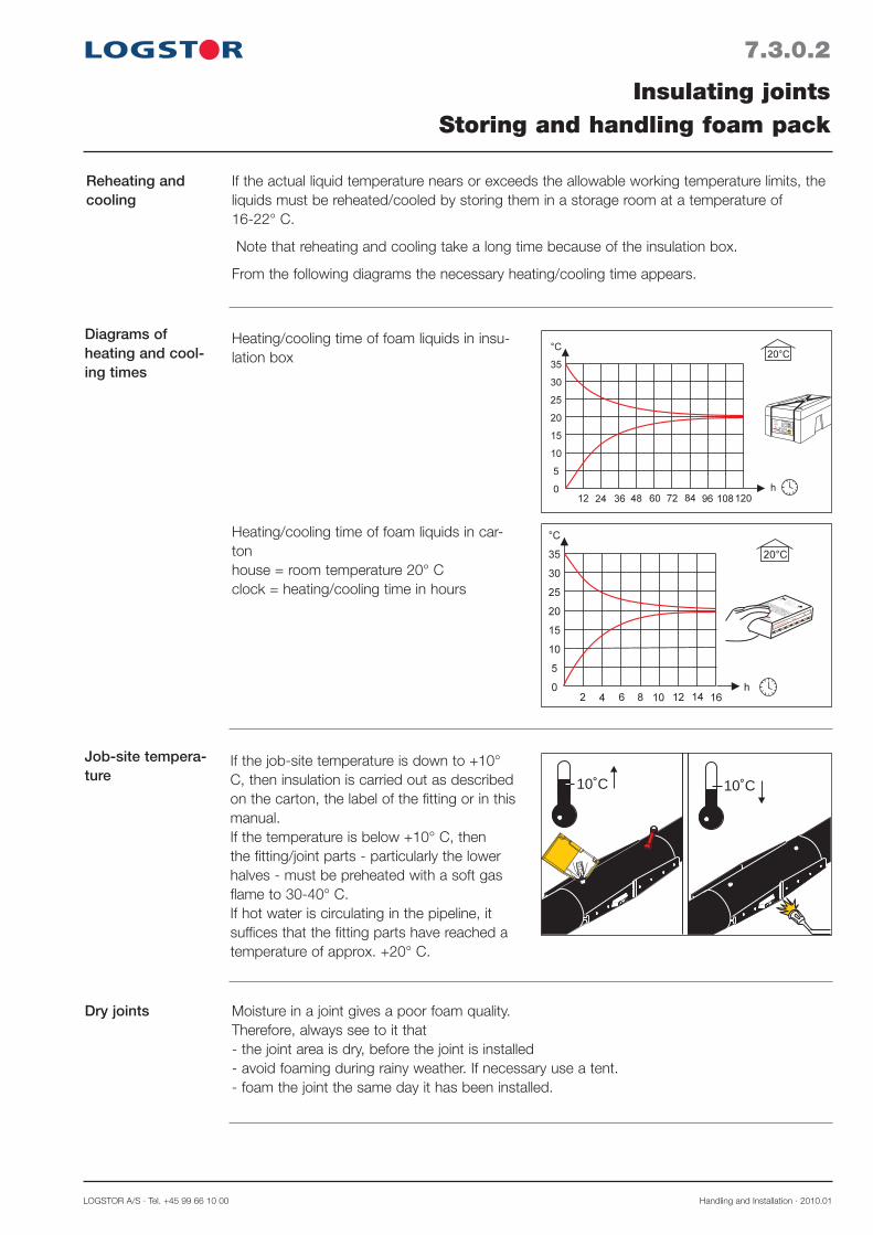
LOGSTOR A/S · Tel. +45 99 66 10 00 Handling and Installation · 2010.01
7.3.0.2
Reheating and cooling
Diagrams of heating and cool-ing times
Job-site tempera-ture
Dry joints
Insulating jointsStoring and handling foam pack
If the actual liquid temperature nears or exceeds the allowable working temperature limits, the liquids must be reheated/cooled by storing them in a storage room at a temperature of 16-22° C.
Note that reheating and cooling take a long time because of the insulation box.
From the following diagrams the necessary heating/cooling time appears.
Moisture in a joint gives a poor foam quality.Therefore, always see to it that- the joint area is dry, before the joint is installed- avoid foaming during rainy weather. If necessary use a tent.- foam the joint the same day it has been installed.
Heating/cooling time of foam liquids in insu-lation box
If the job-site temperature is down to +10° C, then insulation is carried out as described on the carton, the label of the fitting or in this manual.If the temperature is below +10° C, then the fitting/joint parts - particularly the lower halves - must be preheated with a soft gas flame to 30-40° C.If hot water is circulating in the pipeline, it suffices that the fitting parts have reached a temperature of approx. +20° C.
Heating/cooling time of foam liquids in car-ton house = room temperature 20° Cclock = heating/cooling time in hours
81132x1323.96
5
0700000000815 4809
5
10˚C 10˚C
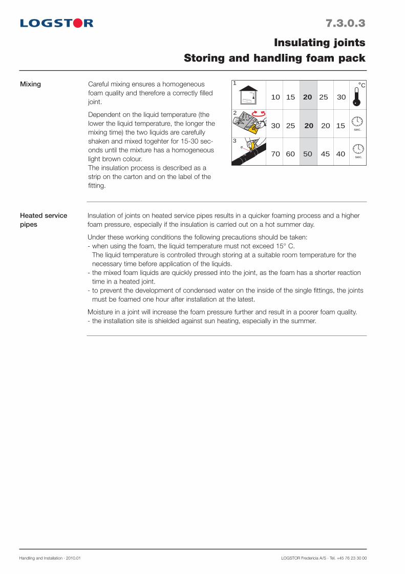
Handling and Installation · 2010.01 LOGSTOR Fredericia A/S · Tel. +45 76 23 30 00
Mixing
Heated service pipes
Insulation of joints on heated service pipes results in a quicker foaming process and a higher foam pressure, especially if the insulation is carried out on a hot summer day.
Under these working conditions the following precautions should be taken: - when using the foam, the liquid temperature must not exceed 15° C.
The liquid temperature is controlled through storing at a suitable room temperature for the necessary time before application of the liquids.
- the mixed foam liquids are quickly pressed into the joint, as the foam has a shorter reaction time in a heated joint.
- to prevent the development of condensed water on the inside of the single fittings, the joints must be foamed one hour after installation at the latest.
Moisture in a joint will increase the foam pressure further and result in a poorer foam quality.- the installation site is shielded against sun heating, especially in the summer.
t°C
10 25
30 20
70
20
20
3495
5
1
2
3
15 30
25 15
60 50 45 40
sec.
sec.
°CCareful mixing ensures a homogeneous foam quality and therefore a correctly filled joint.
Dependent on the liquid temperature (the lower the liquid temperature, the longer the mixing time) the two liquids are carefully shaken and mixed togehter for 15-30 sec-onds until the mixture has a homogeneous light brown colour.The insulation process is described as a strip on the carton and on the label of the fitting.
7.3.0.3
Insulating jointsStoring and handling foam pack
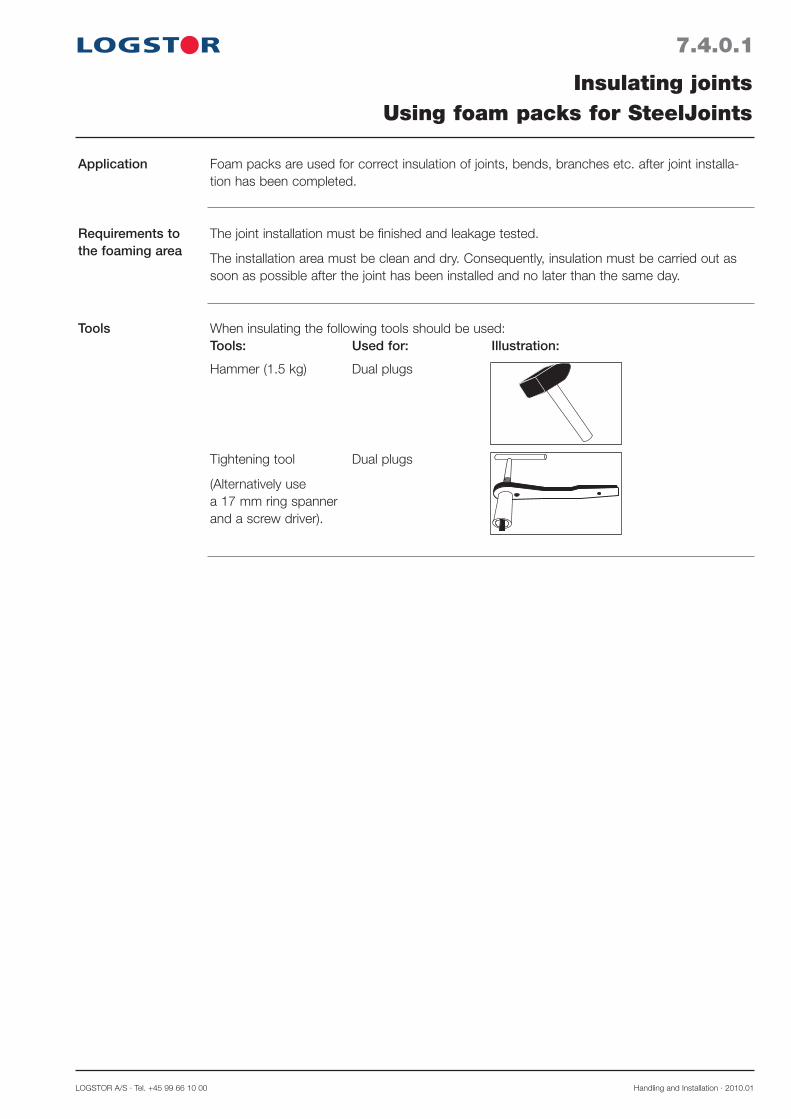
LOGSTOR A/S · Tel. +45 99 66 10 00 Handling and Installation · 2010.01
7.4.0.1
Application
Requirements to the foaming area
Tools
Insulating jointsUsing foam packs for SteelJoints
Foam packs are used for correct insulation of joints, bends, branches etc. after joint installa-tion has been completed.
The joint installation must be finished and leakage tested.
The installation area must be clean and dry. Consequently, insulation must be carried out as soon as possible after the joint has been installed and no later than the same day.
When insulating the following tools should be used:Tools: Used for: Illustration:
Hammer (1.5 kg) Dual plugs
Tightening tool Dual plugs
(Alternatively use a 17 mm ring spannerand a screw driver).

Handling and Installation · 2010.01 LOGSTOR Fredericia A/S · Tel. +45 76 23 30 00
Bend
Position of foaming holes
Taper lock joint
It is important that the foaming holes always face upwards (12 o'clock position). The foam liquid should always be filled into the lower filling hole of the joint to ensure an optimum venting.
45° branch
90° branch
Branch saddle
7.4.0.2
Insulating jointsUsing foam packs for SteelJoints
Straight taper lock branch
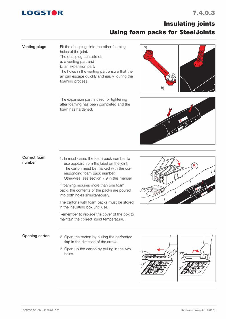
LOGSTOR A/S · Tel. +45 99 66 10 00 Handling and Installation · 2010.01
7.4.0.3
Venting plugs
Correct foam number
Opening carton
Insulating jointsUsing foam packs for SteelJoints
Fit the dual plugs into the other foaming holes of the joint.The dual plug consists of:a. a venting part and b. an expansion part.The holes in the venting part ensure that the air can escape quickly and easily during the foaming process.
1. In most cases the foam pack number to use appears from the label on the joint. The carton must be marked with the cor-responding foam pack number. Otherwise, see section 7.9 in this manual.
If foaming requires more than one foam pack, the contents of the packs are poured into both holes simultaneously.
The cartons with foam packs must be stored in the insulating box until use.
Remember to replace the cover of the box to maintain the correct liquid temperature.
2. Open the carton by pulling the perforated flap in the direction of the arrow.
3. Open up the carton by pulling in the two holes.
The expansion part is used for tightening after foaming has been completed and the foam has hardened.
a)
b)
81132x1323.96
5
0700000000815 4809
5
5

Handling and Installation · 2010.01 LOGSTOR Fredericia A/S · Tel. +45 76 23 30 00
7.4.0.4
Mixing foam liquids
Filling in foam liquid
Insulating jointsUsing foam packs for SteelJoints
2
1
4. Pull at both sides of the bag and remove the clip barrier, so the two liquids mix.
6. Place the nozzle in the open filling hole - the lower hole of the joint.
7. Press the mixing stick into the nozzle which is supported by one hand.
8. Twist the mixing stick back and forth several times until the plastic membrane breaks.
It is important that the penetration is thor-ough, so that the liquids can easily run down into the joint.
5. Mix the liquids by shaking the bag vigor-ously and stirring the two liquids with the built-in mixing stick at the same time. Mix the foam liquids carefully for the number of seconds, appearing from the table on the carton, until the liquid mixture is homogeneous light brown. Hold the mixing stick, not the nozzle.
9. Squeeze the foam liquid into the joint and flatten/wring the bag during filling, so that no air pockets appear behind the liquid in the bag.

LOGSTOR A/S · Tel. +45 99 66 10 00 Handling and Installation · 2010.01
Venting and hardening
Sealing with expansion plugs
!
min. 30 min.
10. Fit the venting part of the dual plug into the filling hole.
Proceed with the next joint. The foam liquid expands in the joint, forcing the air through the venting part.
When the ventilation is complete, a little foam will be forced through the venting holes. The insulation of the joint is complete, when the foam appearing at the holes is hard.
11. Turn the plugs and drive in the expansion part later the same day, however at the earliest 30 minutes after the hardening of the foam.
When turning the plug, tools which may damage the edge of the hole must not be used.
12. Press the plug against the edge of the foaming hole to break any back pressure from the foam insulation.
13. Tighten the nut using the fastening tool.
Note! The red plastic part must not be turned during tightening.
Always turn the dual plug the same day foaming has been carried out.
It is recommended to use the plug spanner (see Tools) which combines screwdriver and ratchet spanner.
7.4.0.5
Insulating jointsUsing foam packs for SteelJoints
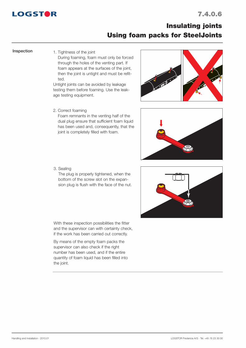
Handling and Installation · 2010.01 LOGSTOR Fredericia A/S · Tel. +45 76 23 30 00
Inspection 1. Tightness of the joint During foaming, foam must only be forced through the holes of the venting part. If foam appears at the surfaces of the joint, then the joint is untight and must be refit-ted.
Untight joints can be avoided by leakage testing them before foaming. Use the leak-age testing equipment.
2. Correct foaming Foam remnants in the venting half of the dual plug ensure that sufficient foam liquid has been used and, consequently, that the joint is completely filled with foam.
3. Sealing The plug is properly tightened, when the bottom of the screw slot on the expan-sion plug is flush with the face of the nut.
With these inspection possibilities the fitter and the supervisor can with certainty check, if the work has been carried out correctly.
By means of the empty foam packs the supervisor can also check if the right number has been used, and if the entire quantity of foam liquid has been filled into the joint.
7.4.0.6
Insulating jointsUsing foam packs for SteelJoints

LOGSTOR A/S · Tel. +45 99 66 10 00 Handling and Installation · 2010.01
7.5.0.1
Application
Tools
Insulating jointsUsing foam packs for joints with welding plug
This section describes the correct insulation with foam pack of joints, sealed with welding plugs: BandJoints, EWJoints and BSJoints.
When foaming and sealing the joints, the following tools should be used:Tool: Used for: Illustration:
BandJoint Plug box with Venting plugs and complete tool set conical welding plugs
Venting holes/plugs
a b
12It is important that the filling holes always face upwards (12 o'clock position).
The foam liquid should always be filled into the lower filling hole of the joint to ensure an optimum venting.
The holes in the venting plug ensure that the air in the joint can escape quickly and easily during the foaming process.
a. BandJoint b. EW- and BSJoint
(ø 25 mm holes must be drilled prior to foaming)
EW- and BSJoints- Drilling machine Drilling venting/filling
with 25 mm cup bit and plug holes- Plug welding tools Installing welding
plugs
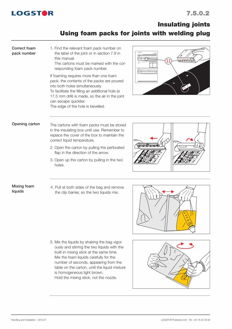
Handling and Installation · 2010.01 LOGSTOR Fredericia A/S · Tel. +45 76 23 30 00
7.5.0.2
Correct foam pack number
Opening carton
Insulating jointsUsing foam packs for joints with welding plug
1. Find the relevant foam pack number on the label of the joint or in section 7.9 in this manual. The cartons must be marked with the cor-responding foam pack number.
If foaming requires more than one foam pack, the contents of the packs are poured into both holes simultaneously.To facilitate the filling an additional hole (ø 17.5 mm drill) is made, so the air in the joint can escape quicklier.The edge of the hole is bevelled.
The cartons with foam packs must be stored in the insulating box until use. Remember to replace the cover of the box to maintain the correct liquid temperature.
2. Open the carton by pulling the perforated flap in the direction of the arrow.
3. Open up the carton by pulling in the two holes.
Mixing foam liquids
4. Pull at both sides of the bag and remove the clip barrier, so the two liquids mix.
5. Mix the liquids by shaking the bag vigor-ously and stirring the two liquids with the built-in mixing stick at the same time. Mix the foam liquids carefully for the number of seconds, appearing from the table on the carton, until the liquid mixture is homogeneous light brown. Hold the mixing stick, not the nozzle.
11
LOGSTOR A/S · Tel. +45 99 66 10 00 Product Catalogue · 2009.05
15.2.6.1
Series 1 pipesø 225-800 mmStraight joints
Series 2 pipesø 225-800 mmStraight joints
Foam packFoam pack numbers for band joint, medium
Series 1 pipesø 225-315 mmBand joint branch
The list below details which foam pack numbers to use for the different Series 1 pipes.
The list below details which foam pack numbers to use for the different Series 2 pipes.
Dimension Joint type outer casing, ø mm 225 250 315 400 450 500 520 560 630 780 800
Band joint 7 8 9 11 2x9 12 2x9 12 10+11 12+13 10+13 Band joint, long 8 9 10 12 12 13 10+11 10+11 10+12 2x13 12+13 Band joint, E 9 10 11 10+11 13 10+12 13 10+12 10+13 2x12+13 2x13 Band joint, E long 10 10 2x9 13 10+12
This list details which foam pack numbers to use for the different Series 1 pipes.
Dimension Joint type outer casing, ø mm 225 250 280 355 450 500 520 560 630 710 800
Band joint 8 9 9 11 12 10+11 10+11 10+11 10+12 12+13 12+13 Band joint, long 9 10 10 2x9 13 10+12 10+12 10+12 12+13 2x13 2x12+13 Band joint, E 10 11 11 12 10+13 10+13 10+13 10+13 12+13 2x12+13 2x12+13 Band joint, E long 11 11 2x9 10+11 10+13
590/77 8 9 10 590/90 9 9 10 590/110 9 9 10 590/125 10 10 11 590/140 10 10 11 Repair joint: 720/77 9 10 11 720/90 10 10 11 720/110 10 10 11 720/125 10 11 2x9 720/140 11 11 2x9
Length of Dimension, main pipe main pipe casing outer casing ø mm L mm/ø branch mm 225 250 315
0700000000815 4809 11
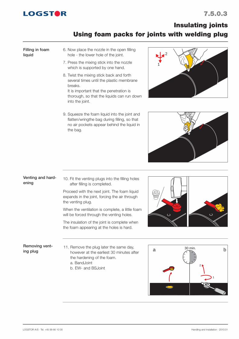
LOGSTOR A/S · Tel. +45 99 66 10 00 Handling and Installation · 2010.01
7.5.0.3
Filling in foam liquid
Venting and hard-ening
Removing vent-ing plug
Insulating jointsUsing foam packs for joints with welding plug
1
2
30 min.a b
6. Now place the nozzle in the open filling hole - the lower hole of the joint.
7. Press the mixing stick into the nozzle which is supported by one hand.
8. Twist the mixing stick back and forth several times until the plastic membrane breaks. It is important that the penetration is thorough, so that the liquids can run down into the joint.
10. Fit the venting plugs into the filling holes after filling is completed.
Proceed with the next joint. The foam liquid expands in the joint, forcing the air through the venting plug.
When the ventilation is complete, a little foam will be forced through the venting holes.
The insulation of the joint is complete when the foam appearing at the holes is hard.
11. Remove the plug later the same day, however at the earliest 30 minutes after the hardening of the foam. a. BandJoint b. EW- and BSJoint
2
1
9. Squeeze the foam liquid into the joint and flatten/wringthe bag during filling, so that no air pockets appear behind the liquid in the bag.

Handling and Installation · 2010.01 LOGSTOR Fredericia A/S · Tel. +45 76 23 30 00
7.5.0.4
Insulating jointsUsing foam packs for joints with welding plug
Installing welding plugs
12. Install welding plugs as described under the individual joints.
The joint is now complete.
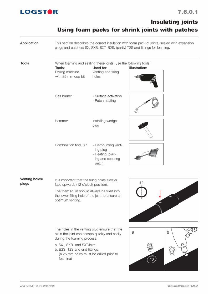
LOGSTOR A/S · Tel. +45 99 66 10 00 Handling and Installation · 2010.01
7.6.0.1
Application
Tools
Insulating jointsUsing foam packs for shrink joints with patches
This section describes the correct insulation with foam pack of joints, sealed with expansion plugs and patches: SX, SXB, SXT, B2S, (partly) T2S and fittings for foaming.
When foaming and sealing these joints, use the following tools:Tools: Used for: Illustration:Drilling machine Venting and filling with 25 mm cup bit holes
Gas burner - Surface activation - Patch heating
Hammer Installing wedge plug
Combination tool, 3P - Dismounting vent-ing plug
- Heating, plac-ing and securing patch
Venting holes/plugs
a b
12It is important that the filling holes always face upwards (12 o'clock position).
The foam liquid should always be filled into the lower filling hole of the joint to ensure an optimum venting.
The holes in the venting plug ensure that the air in the joint can escape quickly and easily during the foaming process.
a. SX-, SXB- and SXTJoint b. B2S, T2S and end fittings
(ø 25 mm holes must be drilled prior to foaming)

Handling and Installation · 2010.01 LOGSTOR Fredericia A/S · Tel. +45 76 23 30 00
7.6.0.2
Insulating jointsUsing foam packs for shrink joints with patches
Correct foam pack number
Opening carton
1. Find the relevant foam pack number on the label of the joint or in section 7.9 in this manual. The cartons must be marked with the cor-responding foam pack number.
If foaming requires more than one foam pack, the contents of the packs are poured into both holes simultaneously.To facilitate the filling an additional hole (ø 17.5 mm drill) is made, so the air in the joint can escape quicklier.The edge of the hole is bevelled.
The cartons with foam packs must be stored in the insulating box until use. Remember to replace the cover of the box to maintain the correct liquid temperature.
2. Open the carton by pulling the perforated flap in the direction of the arrow.
3. Open up the carton by pulling in the two holes.
Mixing foam liquids
4. Pull at both sides of the bag and remove the clip barrier, so the two liquids mix.
5. Mix the liquids by shaking the bag vigor-ously and stirring the two liquids with the built-in mixing stick at the same time. Mix the foam liquids carefully for the number of seconds, appearing from the table on the carton, until the liquid mixture is homogeneous light brown. Hold the mixing stick, not the nozzle.
11
LOGSTOR A/S · Tel. +45 99 66 10 00 Product Catalogue · 2009.05
15.2.6.1
Series 1 pipesø 225-800 mmStraight joints
Series 2 pipesø 225-800 mmStraight joints
Foam packFoam pack numbers for band joint, medium
Series 1 pipesø 225-315 mmBand joint branch
The list below details which foam pack numbers to use for the different Series 1 pipes.
The list below details which foam pack numbers to use for the different Series 2 pipes.
Dimension Joint type outer casing, ø mm 225 250 315 400 450 500 520 560 630 780 800
Band joint 7 8 9 11 2x9 12 2x9 12 10+11 12+13 10+13 Band joint, long 8 9 10 12 12 13 10+11 10+11 10+12 2x13 12+13 Band joint, E 9 10 11 10+11 13 10+12 13 10+12 10+13 2x12+13 2x13 Band joint, E long 10 10 2x9 13 10+12
This list details which foam pack numbers to use for the different Series 1 pipes.
Dimension Joint type outer casing, ø mm 225 250 280 355 450 500 520 560 630 710 800
Band joint 8 9 9 11 12 10+11 10+11 10+11 10+12 12+13 12+13 Band joint, long 9 10 10 2x9 13 10+12 10+12 10+12 12+13 2x13 2x12+13 Band joint, E 10 11 11 12 10+13 10+13 10+13 10+13 12+13 2x12+13 2x12+13 Band joint, E long 11 11 2x9 10+11 10+13
590/77 8 9 10 590/90 9 9 10 590/110 9 9 10 590/125 10 10 11 590/140 10 10 11 Repair joint: 720/77 9 10 11 720/90 10 10 11 720/110 10 10 11 720/125 10 11 2x9 720/140 11 11 2x9
Length of Dimension, main pipe main pipe casing outer casing ø mm L mm/ø branch mm 225 250 315
0700000000815 4809 11
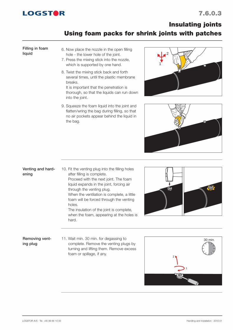
LOGSTOR A/S · Tel. +45 99 66 10 00 Handling and Installation · 2010.01
7.6.0.3
Venting and hard-ening
Insulating jointsUsing foam packs for shrink joints with patches
10. Fit the venting plug into the filling holes after filling is complete. Proceed with the next joint. The foam liquid expands in the joint, forcing air through the venting plug. When the ventilation is complete, a little foam will be forced through the venting holes. The insulation of the joint is complete, when the foam, appearing at the holes is hard.
Filling in foam liquid 2
1
6. Now place the nozzle in the open filling hole - the lower hole of the joint.
7. Press the mixing stick into the nozzle, which is supported by one hand.
8. Twist the mixing stick back and forth several times, until the plastic membrane breaks. It is important that the penetration is thorough, so that the liquids can run down into the joint.
9. Squeeze the foam liquid into the joint and flatten/wring the bag during filling, so that no air pockets appear behind the liquid in the bag.
Removing vent-ing plug
1
2
30 min.11. Wait min. 30 min. for degassing to complete. Remove the venting plugs by turning and lifting them. Remove excess foam or spillage, if any.
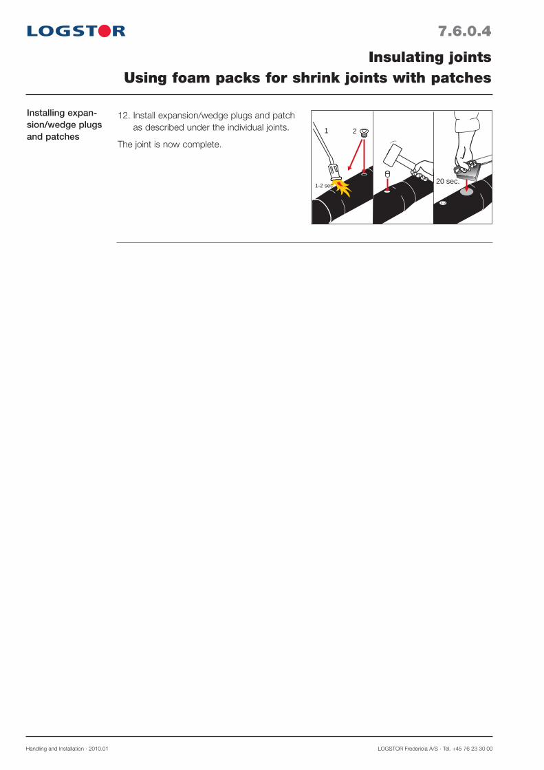
Handling and Installation · 2010.01 LOGSTOR Fredericia A/S · Tel. +45 76 23 30 00
7.6.0.4
Insulating jointsUsing foam packs for shrink joints with patches
Installing expan-sion/wedge plugs and patches
1
1-2 sec.
2
20 sec.
12. Install expansion/wedge plugs and patch as described under the individual joints.
The joint is now complete.

LOGSTOR A/S · Tel. +45 99 66 10 00 Handling and Installation · 2010.01
7.7.0.1
Insulating jointsFoam packs for foaming in alu wrap
Application
Tools
This section describes the correct use of foam packs in connection with alu-wrap, which is primarily used for BXJoints, but also for EWJoints.The wrap also acts as a diffusion barrier.
When foaming in alu-wrap use the following tools:Tools: Used for: Illustration:Rivet tongs Installing pop rivets
Straps Fixing the alu-wrap
Screwdriver Removing venting plug
1. Clean all surfaces in the mounting area.
2. Apply tape around the casing pipe, so it is flush with the pipe end.
1
2
Applying tape

Handling and Installation · 2010.01 LOGSTOR Fredericia A/S · Tel. +45 76 23 30 00
7.7.0.2
Insulating jointsFoam packs for foaming in alu wrap
Covering casing pipe ends
Installing wrap
3. Cover the casing pipe ends with the pro-tective plastic film of the sleeve and fix it with tape.
4. Install the wrap with the foaming hole tur-ning upwards by means of rivets. Fix it with straps or filament tape.
Venting and foaming
5. Foam the joint and install the venting plug. Wait at least 30 min., until degassing has taken place. Remove the venting plug by turning and lifting it.
6. Remove the plastic film and excess foam from the casing. Finish the joint installation according to the instructions for the actual joint type.
1
2
30 min.

LOGSTOR A/S · Tel. +45 99 66 10 00 Handling and Installation · 2010.01
Application The foam pack size stated on the joint or in the tables on the following pages can be replaced by a combination of some other foam packs, if required.
Foam packs for replacement
From the table the alternative possibilities for the use of foam packs appear.Note! Two foam packs replacing one foam pack must be filled in at the same time, using both filling holes.
7.8.0.1
Insulating jointsPossible combinations of foam packs
Foam pack No
Replaceable by foam pack No
1
2
3
4 1+1
5 1+2 2+2
6 2+3 3+3 1+4
2x6 5+7
7 3+4 1+5 2+5
8 4+5 2+6 3+6 1+7
9 5+6 3+7 4+7 1+8 2+8
2x9 8+10 5+11 6+11
10 6+7 5+8 2+9 3+9
11 6+9 3+10 4+10 8+8
12 8+11
13 11+11 8+12

Handling and Installation · 2010.01 LOGSTOR Fredericia A/S · Tel. +45 76 23 30 00
7.9.0.1
Introduction
Contents
Insulating jointsFoam pack numbers for joints - Overview
Joints in the pipe system are best insulated with our foam packs. It is an easy-to-apply meth-od according to which a two-component foam liquid, after mixing and filling, forms an effective insulation with the same properties as in the rest of the pipe system.
Foam pack Nos., alternative use 7.9.0
Foam pack Nos., Single pipe system- SteelJoints, insulation series 1 7.9.1- SteelJoints, insulation series 2 7.9.2- SteelJoints, insulation series 3 7.9.3- SteelJoints, hot tapping 7.9.4- BandJoint, small *) 7.9.5- BandJoint, medium *) 7.9.6- BandJoint, large 7.9.7- EWJoint 7.9.8- SX shrink sleeve 7.9.9- B2S and BS shrink sleeve 7.9.10-T2S shrink sleeve, connecting branch 7.9.11
Foam pack Nos., TwinPipe system 7.10- SteelJoints, insulation series 1 and 2 7.10.1- BandJoint *), insulation series 1 and 2 7.10.2- SX system, insulation series 1 and 2 7.10.3- EW- and B2SJoints, insulation series 1 and 2 7.10.4- TX branch tee coupling, insulation series 1 and 2 7.10.5- T-joint, straight, 2 connecting pieces, insulation series 1 and 2 7.10.6- End fittings, series 1 and 2 7.10.7
Foam pack Nos., Copper pipe system 7.11
Foam pack Nos., Foaming in alu wrap 7.12
*) Including branch band joints

LOGSTOR A/S · Tel. +45 99 66 10 00 Handling and Installation · 2010.01
Series 1 pipesø 400-780 mm
Dimension, main pipe, outer casing ø mm Joint type 400 450 500 520 560 630 780
Branch saddle outer casing ø mm*): 77 5 5 6 5 5 5 6 90 6 6 6 5 5 6 7 110 6 6 6 6 6 6 7 125 6 6 7 6 6 7 7 140 8 8 9 8 8 8 9 160 9 9 9 9 8 9 10 200 10 10 10 10 10 10 11 225 11 10 11 10 10 11 11 250 2x9 2x9 11 11 2x9 2x9 315 12 12 12 10+11
* The quantity of foam liquids has been calculated for the insulation of both the branch tee coupling and the branch bend.
7.9.1.1
Series 1 pipesø 77-315 mm
Foam packFoam pack numbers for the SteelJoints system
The lists below detail which foam pack numbers to use for the different Serie 1 pipes.
Dimension, main pipe, outer casing ø mm Joint type 77 90 110 125 140 160 200 225 250 315
Taper lock joint 0.5 1 2 2 3 4 6 7 8 9 Joint for E-Comp 3 3 4 5 7 8 9 11 90° bend 1 3 4 5 6 8 10 11 45° bend 1 2 3 4 5 7 8 9 11 15° bend 1 2 3 3 5 7 7 8 10 7.5° bend 3 5 6 7 8 10 Straight branch outer casing ø mm: 77 1 2 3 3 4 5 7 7 8 10 90 2 3 4 5 5 7 8 8 10 110 4 4 5 6 7 8 8 10 125 5 5 6 7 8 8 10 140 5 6 7 8 9 10 160 6 8 8 9 10 200 9 9 10 225 9 10 250 10 45° and 90° branch outer casing ø mm*): 77 2 3 3 4 5 5 7 8 8 10 90 3 4 5 5 6 7 8 8 10 110 5 5 6 6 8 8 9 10 125 6 6 7 8 9 9 10 140 7 7 9 9 9 10 160 8 9 10 10 11 200 10 10 11 11 225 11 11 2x9 250 2x9 2x9

Handling and Installation · 2010.01 LOGSTOR Fredericia A/S · Tel. +45 76 23 30 00
7.9.2.1
Series 2 pipesø 77-280 mm
Foam packFoam pack numbers for SteelJoints system
The lists below detail which foam pack numbers to use for the different Series 2 pipes.
Dimension, main pipe, outer casing ø mm Joint type 90 110 125 140 160 180 200 225 250 280
*1) The quantity of foam liquids has been calculated for the insulation of both the branch tee coupling and the branch bend.
*2) Straight branches are not available for ø 180 mm, the quantity of foam liquids is for ø 200 mm
Series 2 pipesø 355-800 mm
Dimension, main pipe, outer casing ø mm Joint type 355 450 500 520 560 630 710
Taper lock joint 1 2 3 4 5 6 8 9 9 Joint for E-Comp 4 5 6 7 9 10 11 90° bend 3 4 5 6 7 10 11 45° bend 2 3 5 6 7 9 10 11 15° bend 2 3 4 5 6 8 9 10 7.5° bend 4 5 6 8 9 10 Straight branch outer casing ø mm: 90 3 4 4 5 6 7 8 9 10 110 4 5 5 6 7 9 9 10 125 5 6 6 7 9 9 10 140 6 7 7 9 10 10 160 7 8 9 10 10 180 9*2) 9 10 10 225 10 11 250 11 45° and 90° branch outer casing ø mm *1): 90 3 4 5 6 6 7 9 9 10 110 5 6 6 7 8 9 10 10 125 6 7 7 8 9 10 10 140 7 8 8 10 10 11 160 9 9 10 10 11 180 10 10 11 11 225 2x9 2x9 2x9 250 2x9 12
Branch saddle outer casing ø mm *1): 90 6 7 7 6 6 7 7 110 6 7 7 7 7 7 8 125 7 8 8 7 7 8 8 140 9 9 9 9 9 9 10 160 9 10 10 10 10 10 10 180 10 10 10 10 10 10 11 225 11 11 11 11 11 11 2x9 250 12 12 2x9 2x9 12 12 280 12 12 12 12 12 12

LOGSTOR A/S · Tel. +45 99 66 10 00 Handling and Installation · 2010.01
7.9.3.1
Foam packFoam pack numbers for SteelJoints system
Series 3 pipesø 400-780 mm
Series 3 pipesø 90-315 mm
The lists below detail which foam pack numbers to use for the different Series 3 pipes.
*1) The quantity of foam liquids has been calculated for the insulation of both the branch tee coupling and the branch bend.
Taper lock joint 3 4 5 6 7 9 10 11 Joint for E-Comp 6 7 8 8 11 11 2x9 90° bend 4 5 6 7 9 11 45° bend 4 5 6 7 8 10 11 2x9 15° bend 3 4 6 6 7 10 10 11 7.5° bend 4 5 6 7 9 10 11
Straight branch outer csing ø mm: 110 5 6 7 7 8 10 10 11 125 6 6 7 8 8 10 10 11 140 6 7 8 8 10 11 11 160 7 8 9 10 11 11 180 9 10 11 11 200 10 11 11 250 11 2x9
45° and 90° branch outer casing ø mm*1): 110 5 6 7 7 8 8 10 11 11 125 7 7 8 8 9 10 11 11 140 8 8 9 9 11 11 11 160 9 9 10 11 11 2x9 180 10 10 11 2x9 2x9 200 11 2x9 2x9 2x9 250 12 12 10+11
Dimension, main pipe, outer casing ø mm Joint type 110 125 140 160 180 200 250 280 315
Dimension, main pipe, outer casing ø mm Joint type 400 500 520 560 630 710 780
Branch saddle outer casing ø mm *1): 110 7 8 8 8 8 9 9 125 8 8 8 8 8 9 9 140 10 10 10 10 10 11 11 160 10 11 10 10 11 11 11 180 10 11 11 11 11 11 11 200 11 11 11 11 11 2x9 2x9 250 12 12 12 12 10+11 10+11 280 10+11 10+11 10+11 10+11 10+11 13 315 13 13 13 10+12 10+12

Handling and Installation · 2010.01 LOGSTOR Fredericia A/S · Tel. +45 76 23 30 00
The figures in ( ) state the actual dimension of the connecting branch/branch bend.
General
Series 1 pipes
Foam packFoam pack numbers for SteelJoints, hot tapping
With a few exceptions the branch tee coupling for steel-in-plastic is always delivered with an outsize connecting branch and matching 90° branch bend.This is done owing to the dimension of the hot tapping valve and wiring the surveillance system. Another foam pack size than the usual for the pipe dimensions in question must therefore be applied.
The figures in ( ) state the actual dimension of the connecting branch/branch bend.
In connection with the dimensions, marked with *), a special branch tee coupling with built-in reduction from ø 200 to ø 160 mm is used.
Series 2 pipes
In connection with the dimensions, marked with *), a special branch tee coupling with built-in reduction from ø 200 to ø 160 mm is used.
125 6 140 7 8 160 7 8 9 180 8 9 9 11 225 9 10 10 11 11 250 10 10 11 11 11 2x9 280 10 11 11 2x9 2x9 2x9 355 7 9 9 10 10 11 450 8 10 10 11 11 2x9 500 8 10 10 11 11 2x9 520 8 9 10 11 11 2x9 560 7 9 10 11 11 11 630 8 10 10 11 11 2x9 710 8 10 10 11 11 2x9 780 9 10 11 11 11 2x9
Branch ø mm Main pipe 110 125 140 *160 180 225 ø out. mm (125) (140) (160) (200/160) (200)
110 6 125 6 8 140 7 7 9 160 7 8 9 11 200 8 9 9 11 10 225 9 9 10 11 11 2x9 250 9 10 10 11 11 2x9 315 10 11 11 2x9 2x9 2x9 400 7 9 9 10 10 11 450 7 9 9 10 10 11 500 7 9 10 11 10 11 520 7 8 9 10 10 11 560 6 8 9 10 10 11 630 7 9 9 10 10 11 710 7 9 10 11 11 11 780 8 10 10 11 11 2x9
Branch ø out. mm Main pipe 90 110 125 *140 *160 200 ø out. mm (125) (140) (160) (200/160) (200/160) (225)
7.9.4.1
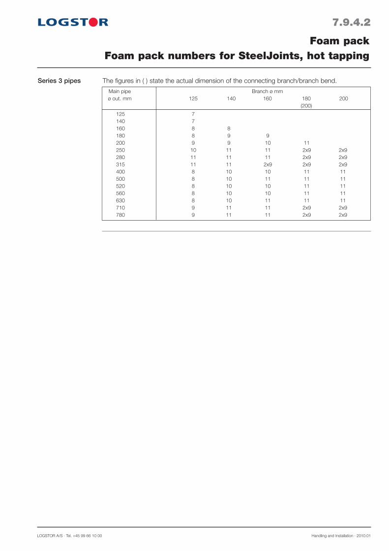
LOGSTOR A/S · Tel. +45 99 66 10 00 Handling and Installation · 2010.01
Series 3 pipes The figures in ( ) state the actual dimension of the connecting branch/branch bend.
125 7 140 7 160 8 8 180 8 9 9 200 9 9 10 11 250 10 11 11 2x9 2x9 280 11 11 11 2x9 2x9 315 11 11 2x9 2x9 2x9 400 8 10 10 11 11 500 8 10 11 11 11 520 8 10 10 11 11 560 8 10 10 11 11 630 8 10 11 11 11 710 9 11 11 2x9 2x9 780 9 11 11 2x9 2x9
Main pipe Branch ø mm ø out. mm 125 140 160 180 200 (200)
7.9.4.2
Foam packFoam pack numbers for SteelJoints, hot tapping

Handling and Installation · 2010.01 LOGSTOR Fredericia A/S · Tel. +45 76 23 30 00
Series 2 pipesø 110-180 mmStraight joints
The list below details which foam pack numbers to use for the different Series 2 pipes.
Dimension Joint type outer casing, ø mm 110 125 140 160 180
BandJoint 2 3 4 5 6 BandJoint, long 3 4 5 6 7 BandJoint, E 5 6 7 8 BandJoint, E long 6 7 8 9
The list below details which foam pack numbers to use for the different Series 1 pipes.Series 1 pipesø 90-200 mmBand joint branch
7.9.5.1
Series 1 pipesø 90-200 mmStraight joints
Foam packFoam pack numbers for BandJoint, small
BandJoint 1 2 2 3 4 6 BandJoint, long 1 3 4 4 6 7 BandJoint, E 4 5 5 7 8 BandJoint, E long 5 6 6 7 9
Dimension Joint type outer casing, ø mm 90 110 125 140 160 200
The list below details which foam pack numbers to use for the different Series 1 pipes.
570/77 4 5 5 6 6 8 570/90 5 6 6 6 7 8 570/110 6 7 7 8 9 570/125 8 8 8 9 570/140 8 9 10 Repair joint: 700/77 5 6 6 7 7 9 700/90 6 7 7 7 8 9 700/110 7 7 8 8 10 700/125 9 9 9 10 700/140 9 10 10
Length of Dimension, main pipe main pipe casing outer casing ø mm L mm/ø branch mm 90 110 125 140 160 200

LOGSTOR A/S · Tel. +45 99 66 10 00 Handling and Installation · 2010.01
7.9.5.2
Foam packFoam pack numbers for BandJoint, small
Series 3 pipesø 125-200 mm
BandJoint 3 4 5 6 7 BandJoint, long 5 6 7 7 8 BandJoint, E 6 7 8 8 9 BandJoint, E long 6 7 8 9 10
Dimension Joint type outer casing ø mm 125 140 160 180 200
The list below details which foam pack numbers to use for the different Series 3 pipes.
Series 3 pipesø 125-180 mmBandJoint branch
The list below details which foam pack numbers to use for the different Series 3 pipes.
Series 2 pipesø 110-180 mmBandjoint branch
The list below details which foam pack numbers to use for the different Series 2 pipes.
570/90 6 6 7 7 8 570/110 7 7 8 8 8 570/125 8 8 8 9 570/140 9 9 10 Repair joint: 700/90 7 7 8 8 9 700/110 8 8 8 9 9 700/125 9 9 9 10 700/140 10 10 10
Length of Dimension, main pipe main pipe casing outer casing ø mm L mm/ø branch mm 110 125 140 160 180
570/90 7 7 8 8 570/110 7 8 8 9 570/125 8 8 9 9 570/140 9 9 10 Repair joint: 700/90 8 8 9 9 700/110 8 9 9 10 700/125 9 9 10 10 700/140 10 10 10
Length of Dimension, main pipe main pipe casing outer casing ø mm L mm/ø branch mm 125 140 160 180

Handling and Installation · 2010.01 LOGSTOR Fredericia A/S · Tel. +45 76 23 30 00
7.9.6.1
Series 1 pipesø 225-800 mmStraight joints
Series 2 pipesø 225-800 mmStraight joints
Foam packFoam pack numbers for BandJoint, medium
Series 1 pipesø 225-315 mmBandJoint branch
The list below details which foam pack numbers to use for the different Series 1 pipes.
The list below details which foam pack numbers to use for the different Series 2 pipes.
Dimension Joint type outer casing, ø mm 225 250 315 400 450 500 520 560 630 780 800
BandJoint 7 8 9 11 2x9 12 2x9 12 10+11 12+13 10+13 BandJoint, long 8 9 10 12 12 13 10+11 10+11 10+12 2x13 12+13 BandJoint, E 9 10 11 10+11 13 10+12 13 10+12 10+13 2x12+13 2x13 BandJoint, E long 10 10 2x9 13 10+12
This list details which foam pack numbers to use for the different Series 1 pipes.
Dimension Joint type outer casing, ø mm 225 250 280 355 450 500 520 560 630 710 800
BandJoint 8 9 9 11 12 10+11 10+11 10+11 10+12 12+13 12+13 BandJoint, long 9 10 10 2x9 13 10+12 10+12 10+12 12+13 2x13 2x12+13 BandJoint, E 10 11 11 12 10+13 10+13 10+13 10+13 12+13 2x12+13 2x12+13 BandJoint, E long 11 11 2x9 10+11 10+13
590/77 8 9 10 590/90 9 9 10 590/110 9 9 10 590/125 10 10 11 590/140 10 10 11 Repair joint: 720/77 9 10 11 720/90 10 10 11 720/110 10 10 11 720/125 10 11 2x9 720/140 11 11 2x9
Length of Dimension, main pipe main pipe casing outer casing ø mm L mm/ø branch mm 225 250 315

LOGSTOR A/S · Tel. +45 99 66 10 00 Handling and Installation · 2010.01
7.9.6.2
Foam packFoam pack numbers for BandJoint, medium
Series 3 pipeø 250-780 mm Straight joints
The list below details which foam pack numbers to use for the different Series 3 pipes.
Dimension Joint type outer casing ø mm 250 280 315 400 500 520 560 630 710 780
Series 3 pipesø 250-315 mmBandJoint branches
The table details which foam pack numbers to use for the different Series 3 pipes.
BandJoint 9 10 11 12 13 13 10+12 10+13 12+13 2x13 BandJoint, long 10 11 2x9 10+11 10+13 10+13 10+13 12+13 2x12+13 3x13 BandJoint, E 11 2x9 2x9 10+12 BandJoint, E long 2x9 2x9 12 10+13 2x13 2x13 2x12+13 3x13 2x13+2x12 4x13
Series 2 pipesø 225-355 mmBandJoint branch
This list details which foam pack numbers to use for the different Series 2 pipes.
590/90 9 10 10 590/110 10 10 11 590/125 10 10 11 590/140 11 11 11 Repair joint: 720/90 10 11 11 720/110 11 11 11 720/125 11 11 2x9 720/140 11 2x9 2x9
Length of Dimension, main pipe main pipe casing outer casing ø mm L mm/ø branch mm 225 250 280
590/90 10 11 11 590/110 11 11 11 590/125 11 11 2x9 590/140 11 11 2x9 Repair joint: 720/90 11 2x9 2x9 720/110 11 2x9 2x9 720/125 2x9 2x9 12 720/140 2x9 2x9 12
Length of Dimension, main pipe main pipe casing outer casing ø mm L mm/ø branch mm 250 280 315

Handling and Installation · 2010.01 LOGSTOR Fredericia A/S · Tel. +45 76 23 30 00
7.9.7.1
Series 2 pipes
Foam packFoam pack numbers for BandJoint, large
Series 1 pipesø 900-1200 mm(2-part)
Series 2 or 3 pipes are not as such available in these dimensions as they are often made especially for a customer in accordance with project descriptions.Please contact LOGSTOR in these cases regarding the correct dosage of foam.
Dimension main pipe Outer casing ø mm 900 1000 1100 1200 (at steel pipe ø mm) (700) (800) (900) (1000)
Foam pack nos. 2+13 2x12+13 2x12+13 3x13
This list details which foam pack numbers to use for the different Series 1 pipes.
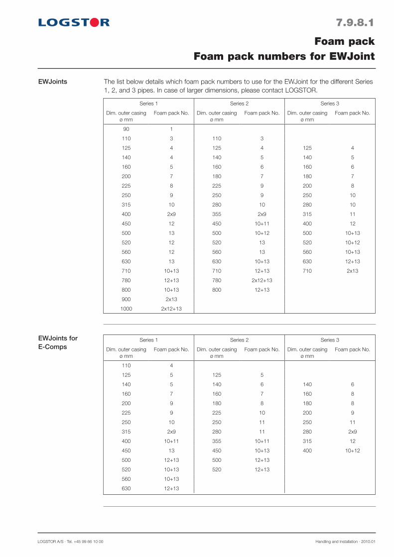
LOGSTOR A/S · Tel. +45 99 66 10 00 Handling and Installation · 2010.01
EWJoints for E-Comps
EWJoints
Series 1 Series 2 Series 3
Dim. outer casing ø mm
Foam pack No. Dim. outer casing ø mm
Foam pack No. Dim. outer casing ø mm
Foam pack No.
90 1
110 3 110 3
125 4 125 4 125 4
140 4 140 5 140 5
160 5 160 6 160 6
200 7 180 7 180 7
225 8 225 9 200 8
250 9 250 9 250 10
315 10 280 10 280 10
400 2x9 355 2x9 315 11
450 12 450 10+11 400 12
500 13 500 10+12 500 10+13
520 12 520 13 520 10+12
560 12 560 13 560 10+13
630 13 630 10+13 630 12+13
710 10+13 710 12+13 710 2x13
780 12+13 780 2x12+13
800 10+13 800 12+13
900 2x13
1000 2x12+13
The list below details which foam pack numbers to use for the EWJoint for the different Series 1, 2, and 3 pipes. In case of larger dimensions, please contact LOGSTOR.
Series 1 Series 2 Series 3
Dim. outer casing ø mm
Foam pack No. Dim. outer casing ø mm
Foam pack No. Dim. outer casing ø mm
Foam pack No.
110 4
125 5 125 5
140 5 140 6 140 6
160 7 160 7 160 8
200 9 180 8 180 8
225 9 225 10 200 9
250 10 250 11 250 11
315 2x9 280 11 280 2x9
400 10+11 355 10+11 315 12
450 13 450 10+13 400 10+12
500 12+13 500 12+13
520 10+13 520 12+13
560 10+13
630 12+13
7.9.8.1
Foam packFoam pack numbers for EWJoint

Handling and Installation · 2010.01 LOGSTOR Fredericia A/S · Tel. +45 76 23 30 00
7.9.9.1
Foam packFoam pack numbers for SX shrink sleeve
Series 1 pipesJoint type
Dimension, main pipe outer casing ø mm
90 110 125 140 160 200 225 250 315 400 450
Straight joint 1 3 3 4 5 7 8 9 10 2x9 12
Reduction joint*) ← 1 2 3 4 6 7 7 10 11 2x9
SXB bend joint 4 5 5 6 7 11 11 10 12
SXT branch, outer casing ø mm:
90 5 5 6 7 7 8 9 9 10
110 6 7 8 8 9 2x6 2x6 11
125 7 8 8 9 2x6 2x6 11
140 8 9 2x6 10 10 11
160 10 11 11 11
200 2x9 2x9 2x9
Joint type
Dimension, main pipe outer casing ø mm
110 125 140 160 180 225 250 280 355 450
Straight joint 3 4 5 6 7 9 9 10 2x9 10+11
Reduction joint*) ← 3 4 5 6 8 8 9 11 12
SXB bend joint 5 6 7 8 11 2x9 11 13
SXT branch, outer casing ø mm:
110 7 8 8 9 9 10 10 10
125 8 8 9 9 10 10 10
140 9 9 2x6 11 11 11
160 10 11 11 11
180 2x9 2x9 12
Series 2 pipes
Joint type
Dimension, main pipe outer casing ø mm
125 140 160 180 200 250 280 315 400
Straight joint 4 5 6 7 8 10 11 11 12
Reduction joint*) ← 4 5 6 7 9 10 10 2x9
SXB -bend joint 6 7 8 11 11 2x9 10+12 13
SXT-branch, outer casing ø mm:
125 8 8 9 9 2x6 11 11 11
140 9 9 2x6 2x6 11 11 2x9
160 10 11 11 2x9 2x9
180 2x9 12 12 10+11
200 12 12 10+11
Series 3 pipes
*) From stated dimension to the next smaller dimension. Foam pack numbers for SXT also apply to hot tapping.
*) From stated dimension to the next smaller dimension. Foam pack numbers for SXT also apply to hot tapping.
*) From stated dimension to the next smaller dimension. Foam pack numbers for SXT also apply to hot tapping.
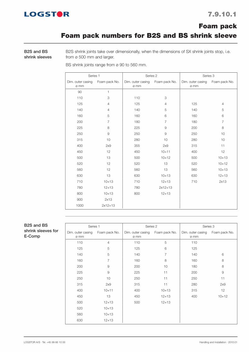
LOGSTOR A/S · Tel. +45 99 66 10 00 Handling and Installation · 2010.01
7.9.10.1
Foam packFoam pack numbers for B2S and BS shrink sleeve
B2S and BS shrink sleeves
B2S shrink joints take over dimensionally, when the dimensions of SX shrink joints stop, i.e. from ø 500 mm and larger.
BS shrink joints range from ø 90 to 560 mm.
B2S and BS shrink sleeves for E-Comp
Series 1 Series 2 Series 3
Dim. outer casing ø mm
Foam pack No. Dim. outer casing ø mm
Foam pack No. Dim. outer casing ø mm
Foam pack No.
90 1
110 3 110 3
125 4 125 4 125 4
140 4 140 5 140 5
160 5 160 6 160 6
200 7 180 7 180 7
225 8 225 9 200 8
250 9 250 9 250 10
315 10 280 10 280 10
400 2x9 355 2x9 315 11
450 12 450 10+11 400 12
500 13 500 10+12 500 10+13
520 12 520 13 520 10+12
560 12 560 13 560 10+13
630 13 630 10+13 630 12+13
710 10+13 710 12+13 710 2x13
780 12+13 780 2x12+13
800 10+13 800 12+13
900 2x13
1000 2x12+13
Series 1 Series 2 Series 3
Dim. outer casing ø mm
Foam pack No. Dim. outer casing ø mm
Foam pack No. Dim. outer casing ø mm
Foam pack No.
110 4 110 5 110
125 5 125 6 125
140 5 140 7 140 6
160 7 160 8 160 8
200 9 200 10 180 8
225 9 225 11 200 9
250 10 250 11 250 11
315 2x9 315 11 280 2x9
400 10+11 400 10+13 315 12
450 13 450 12+13 400 10+12
500 12+13 500 12+13
520 10+13
560 10+13
630 12+13

Handling and Installation · 2010.01 LOGSTOR Fredericia A/S · Tel. +45 76 23 30 00
7.9.11.1
Foam packFoam pack numbers for T2SJoint
T2SJoint T2S shrink sleeves for branching require insulation shells on the main pipe, but foam packs on the flexible connecting branch piece.
The foam quantities in the table are valid for the connecting branch piece.
Connecting branch pc.
ø mm
Dimension main pipe, outer casing,
ø mm
110-315Foam pack
No.
140-315Foam pack
No.
77-90 3 -
110-125 - 5

LOGSTOR A/S · Tel. +45 99 66 10 00 Handling and Installation · 2010.01
Series 1 pipesø 125-315 mm
7.10.1.1
Foam pack, TwinPipe systemFoam pack numbers for the SteelJoints system
The list below details which foam pack numbers to use for the different Series 1 pipes.
Joint typeMain pipe, outer casing ø mm
125 140 160 200 225 250 315
Taper lock joint (incl. reduction) 3 4 5 7 8 9 11
90° bend 4 6 7 9 10 11
Straight branch for outer casing, ø mm
110 5 6 6 8 9 10 11
125 5 6 7 8 9 10 11
140 6 7 8 9 10 11
160 7 9 9 10 11
200 10 10 11
225 10 2x9
250 2x9
Hot tapping. Branch for outer casing ø mm
110 (FlexPipe) 6 7 8 9 10 11
125 6 7 8 9 10 11
140 7 8 9 10 11
160 9 10 10 2x9
200 11 11 2x9
Branch tee coupling with 2 connecting pieces for outer casing ø 110 mm
(77, 90, 110) 7 8 9 10 10 11 2x9
Series 2 pipesø 140-280 mm
The list below details which foam pack numbers to use for the different Series 2 pipes.
Joint typeMain pipe, outer casing ø mm
140 160 180 225 250 280
Taper lock joint (incl. reduction) 4 6 6 8 9 10
90° bend 6 7 8 10 11
Straight branch for outer casing ø mm
110 6 7 7 9 10 10
140 7 7 8 10 10 11
160 8 8 10 10 11
180 10 10 11
225 11 11
Hot tapping. Branch for outer casing ø mm
110 (FlexPipe) 7 8 9 10 11
140 7 8 10 10 11
160 8 10 10 11
180 10 10 11
225 11 11
Branch tee coupling 2 connecting pieces for outer casing ø 110 mm
(77, 90, 110) 8 9 9 11 11 2x9
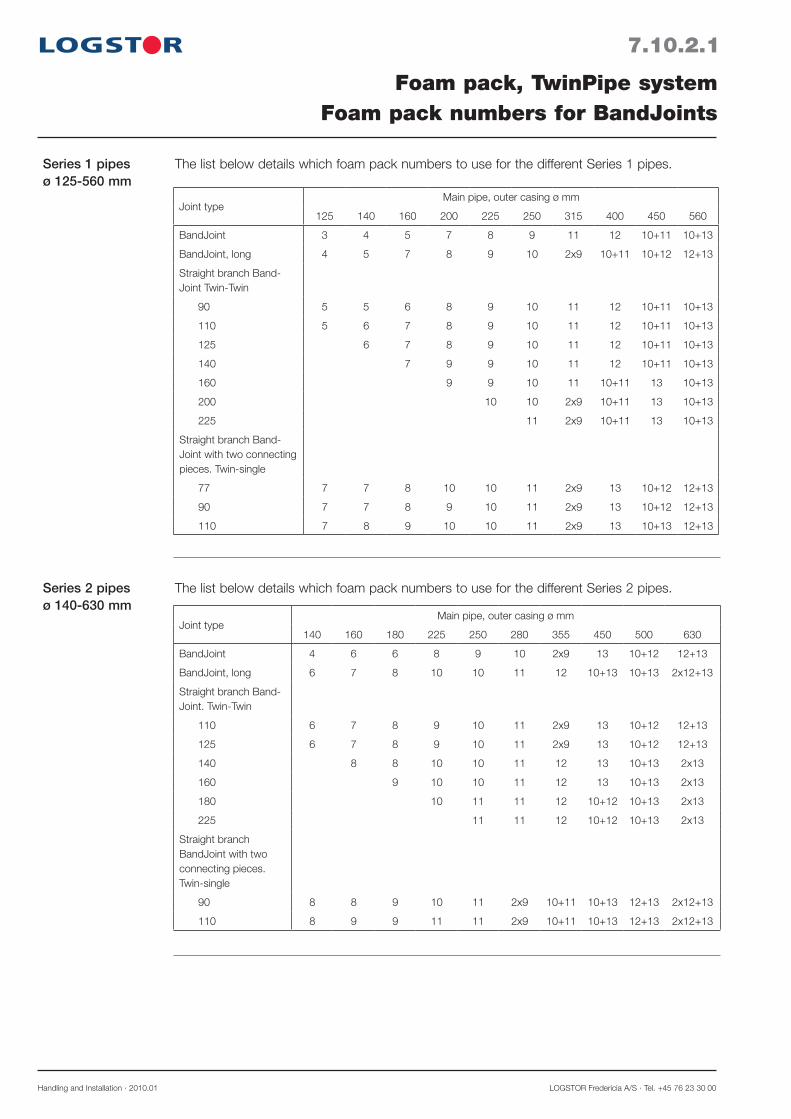
Handling and Installation · 2010.01 LOGSTOR Fredericia A/S · Tel. +45 76 23 30 00
Series 1 pipesø 125-560 mm
7.10.2.1
Foam pack, TwinPipe systemFoam pack numbers for BandJoints
The list below details which foam pack numbers to use for the different Series 1 pipes.
Series 2 pipesø 140-630 mm
The list below details which foam pack numbers to use for the different Series 2 pipes.
Joint typeMain pipe, outer casing ø mm
125 140 160 200 225 250 315 400 450 560
BandJoint 3 4 5 7 8 9 11 12 10+11 10+13
BandJoint, long 4 5 7 8 9 10 2x9 10+11 10+12 12+13
Straight branch Band-Joint Twin-Twin
90 5 5 6 8 9 10 11 12 10+11 10+13
110 5 6 7 8 9 10 11 12 10+11 10+13
125 6 7 8 9 10 11 12 10+11 10+13
140 7 9 9 10 11 12 10+11 10+13
160 9 9 10 11 10+11 13 10+13
200 10 10 2x9 10+11 13 10+13
225 11 2x9 10+11 13 10+13
Straight branch Band-Joint with two connecting pieces. Twin-single
77 7 7 8 10 10 11 2x9 13 10+12 12+13
90 7 7 8 9 10 11 2x9 13 10+12 12+13
110 7 8 9 10 10 11 2x9 13 10+13 12+13
Joint typeMain pipe, outer casing ø mm
140 160 180 225 250 280 355 450 500 630
BandJoint 4 6 6 8 9 10 2x9 13 10+12 12+13
BandJoint, long 6 7 8 10 10 11 12 10+13 10+13 2x12+13
Straight branch Band-Joint. Twin-Twin
110 6 7 8 9 10 11 2x9 13 10+12 12+13
125 6 7 8 9 10 11 2x9 13 10+12 12+13
140 8 8 10 10 11 12 13 10+13 2x13
160 9 10 10 11 12 13 10+13 2x13
180 10 11 11 12 10+12 10+13 2x13
225 11 11 12 10+12 10+13 2x13
Straight branch BandJoint with two connecting pieces. Twin-single
90 8 8 9 10 11 2x9 10+11 10+13 12+13 2x12+13
110 8 9 9 11 11 2x9 10+11 10+13 12+13 2x12+13
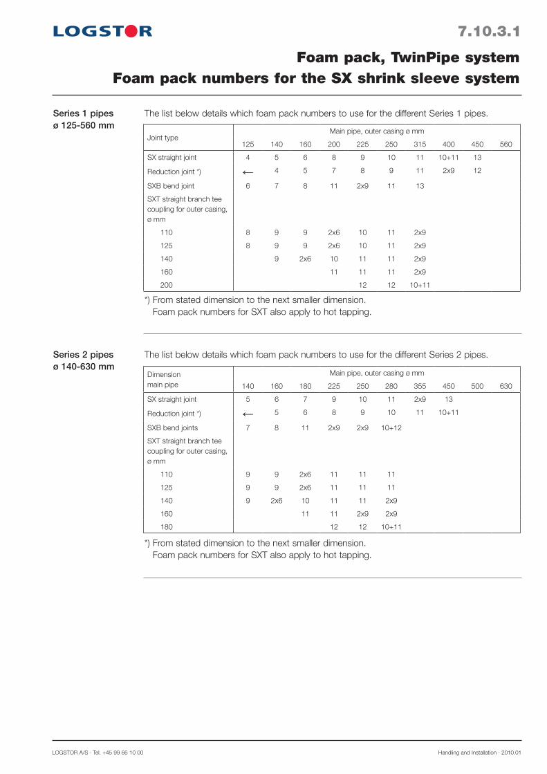
LOGSTOR A/S · Tel. +45 99 66 10 00 Handling and Installation · 2010.01
Series 1 pipesø 125-560 mm
7.10.3.1
Foam pack, TwinPipe systemFoam pack numbers for the SX shrink sleeve system
The list below details which foam pack numbers to use for the different Series 1 pipes.
Joint typeMain pipe, outer casing ø mm
125 140 160 200 225 250 315 400 450 560
SX straight joint 4 5 6 8 9 10 11 10+11 13
Reduction joint *) ← 4 5 7 8 9 11 2x9 12
SXB bend joint 6 7 8 11 2x9 11 13
SXT straight branch tee coupling for outer casing, ø mm
110 8 9 9 2x6 10 11 2x9
125 8 9 9 2x6 10 11 2x9
140 9 2x6 10 11 11 2x9
160 11 11 11 2x9
200 12 12 10+11
Series 2 pipesø 140-630 mm
The list below details which foam pack numbers to use for the different Series 2 pipes.
Dimensionmain pipe
Main pipe, outer casing ø mm
140 160 180 225 250 280 355 450 500 630
SX straight joint 5 6 7 9 10 11 2x9 13
Reduction joint *) ← 5 6 8 9 10 11 10+11
SXB bend joints 7 8 11 2x9 2x9 10+12
SXT straight branch tee coupling for outer casing, ø mm
110 9 9 2x6 11 11 11
125 9 9 2x6 11 11 11
140 9 2x6 10 11 11 2x9
160 11 11 2x9 2x9
180 12 12 10+11
*) From stated dimension to the next smaller dimension. Foam pack numbers for SXT also apply to hot tapping.
*) From stated dimension to the next smaller dimension. Foam pack numbers for SXT also apply to hot tapping.

Handling and Installation · 2010.01 LOGSTOR Fredericia A/S · Tel. +45 76 23 30 00
Series 1 pipesø 125-560 mm
7.10.4.1
Foam pack, TwinPipe systemFoam pack numbers for EW- and B2SJoints
The list below details which foam pack numbers to use for the different Series 1 pipes.
Joint typeMain pipe, outer casing ø mm
125 140 160 200 225 250 315 400 450 560
EW weld joint 8 9 10 11 10+11 13 10+13
B2S shrink sleeve 4 5 6 8 9 10 11 10+11 13 10+13
Series 2 pipesø 140-630 mm
The list below details which foam pack numbers to use for the different Series 2 pipes.
Joint typeMain pipe, outer casing ø mm
140 160 180 225 250 280 355 450 500 630
EW weld joint 9 10 11 2x9 13 10+13 2x13
B2S shrink sleeve 5 6 7 9 10 11 2x9 13 10+13 2x13
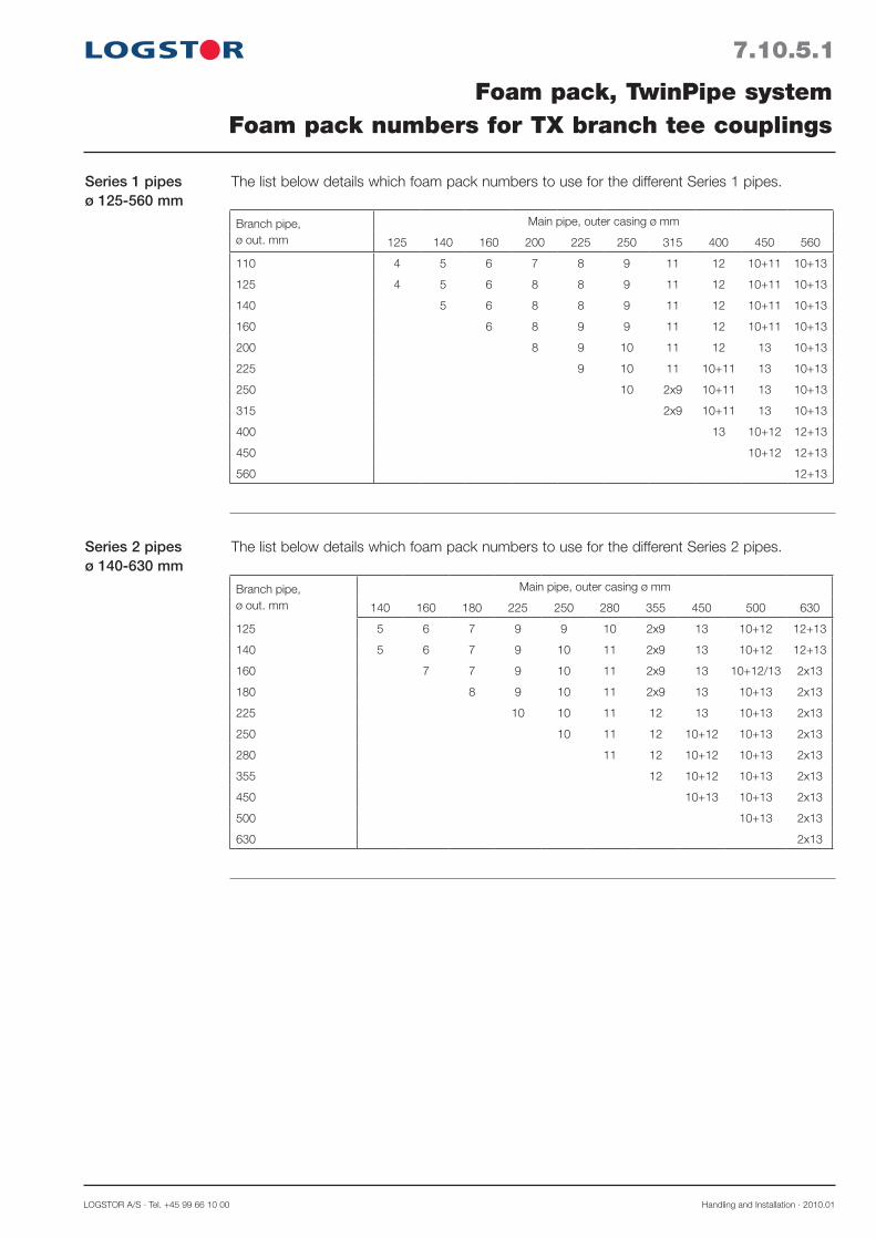
LOGSTOR A/S · Tel. +45 99 66 10 00 Handling and Installation · 2010.01
Series 1 pipesø 125-560 mm
7.10.5.1
Foam pack, TwinPipe systemFoam pack numbers for TX branch tee couplings
The list below details which foam pack numbers to use for the different Series 1 pipes.
Branch pipe,ø out. mm
Main pipe, outer casing ø mm
125 140 160 200 225 250 315 400 450 560
110 4 5 6 7 8 9 11 12 10+11 10+13
125 4 5 6 8 8 9 11 12 10+11 10+13
140 5 6 8 8 9 11 12 10+11 10+13
160 6 8 9 9 11 12 10+11 10+13
200 8 9 10 11 12 13 10+13
225 9 10 11 10+11 13 10+13
250 10 2x9 10+11 13 10+13
315 2x9 10+11 13 10+13
400 13 10+12 12+13
450 10+12 12+13
560 12+13
Series 2 pipesø 140-630 mm
The list below details which foam pack numbers to use for the different Series 2 pipes.
Branch pipe,ø out. mm
Main pipe, outer casing ø mm
140 160 180 225 250 280 355 450 500 630
125 5 6 7 9 9 10 2x9 13 10+12 12+13
140 5 6 7 9 10 11 2x9 13 10+12 12+13
160 7 7 9 10 11 2x9 13 10+12/13 2x13
180 8 9 10 11 2x9 13 10+13 2x13
225 10 10 11 12 13 10+13 2x13
250 10 11 12 10+12 10+13 2x13
280 11 12 10+12 10+13 2x13
355 12 10+12 10+13 2x13
450 10+13 10+13 2x13
500 10+13 2x13
630 2x13

Handling and Installation · 2010.01 LOGSTOR Fredericia A/S · Tel. +45 76 23 30 00
7.10.6.1
Foam pack, TwinPipe systemFoam pack numbers for T-joints with 2 connecting pieces
Series 1 pipesø 140-450 mm
The list below details which foam pack numbers to use for the different Series 1 pipes.
Branch, ø mmMain pipe, outer casing ø mm
125 140 160 200 225 250 315 400 450
77 6 7 8 9 9 10 11 10+11 13
90 7 7 8 9 10 10 2x9 10+11 13
110 8 8 9 10 10 11 2x9 10+11 13
Series 2 pipesø 140-450 mm
The list below details which foam pack numbers to use for the different Series 2 pipes.
Branch, ø mmMain pipe, outer casing ø mm
125 140 160 180 225 250 280 355 450
77 6 7 8 8 10 10 11 12 13
90 7 8 8 9 10 11 11 12 10+12
110 8 8 9 9 10 11 11 12 10+12

LOGSTOR A/S · Tel. +45 99 66 10 00 Handling and Installation · 2010.01
7.10.7.1
Foam pack, TwinPipe systemFoam pack numbers for end fittings
Series 1 pipesø 125-560 mm
The list below details which foam pack numbers to use for the different Series 1 end fittings.
TwinPipe, ø. out mm 125 140 160 200 225 250 315 400 450 560
Foam pack No. 1 2 3 6 7 8 10 2x9 12 10+12
Series 2 pipesø 140-630 mm
The list below details which foam pack numbers to use for the different Series 2 end fittings.
TwinPipe, ø. out mm 140 160 180 225 250 280 355 450 500 630
Foam pack No. 2 4 5 7 8 9 11 12 10+11 10+13

Handling and Installation · 2010.01 LOGSTOR Fredericia A/S · Tel. +45 76 23 30 00
7.11.0.1
Copper pipe systemFoam pack
Application Foam packs are used for all types of copper pipe joints.
Whether the joints is on single pipes, TwinPipes or double pipes, foam quantities for insulation series 1 corresponding to the respective joint and pipe type are used.

LOGSTOR A/S · Tel. +45 99 66 10 00 Handling and Installation · 2010.01
7.12.0.1
Foam packFoam pack numbers for foaming in alu wrap
Application When foaming in alu wrap prior to joint installation foam pack numbers, corresponding to straight casing joints of steel fittings (section 7.9.1-3) or BandJoints (sections 7.9.5-7).

Handling and Installation · 2010.01 LOGSTOR Fredericia A/S · Tel. +45 76 23 30 00
7.13.0.1
Application
Installing insula-tion shells
Insulating jointsInsulation shells
Insulation shells are used in connection with: BXJoints, C2L repair joints, and partly T2S branch joint.They may also be used as an alternative to direct foaming. Contact LOGSTOR.
Fit the insulation shells tightly between the casing pipes, using adhesive tape if required. All surfaces must be CLEAN and DRY.
See section 23.4.4 for installation with alarm wires.
Shorten the insulation shells to make them fit tightly between the casing pipes.
Reductions with insulation shells
Examples of adapting insulation shells in connec-tion with reduction with shrink joints.
a. 1 dimensional offset b. 2-3 dimensional offsets
Use 2 different sets of shells, fitting the actual casing diameters.
a
b

LOGSTOR A/S · Tel. +45 99 66 10 00 Handling and Installation · 2010.01
7.14.0.1
Overview
Liquid temperature
Storage temperature
Job-site temperature
Insulating jointsCan foam
Correct dosing of the foam liquids is ensured by measuring out the 2 liquids according to the liter specification on page 7.14.0.2, based upon corresponding foam pack Nos.. The following factors are important for a correct foaming process:- Liquid temperature- Job-site temperature- Dry joints- MixingPay attention to whether it is legal or not to openly mix foam liquids in your country.
10 15 25 30
40 30 20 15
70 60 50 45 40
20
25
20°°C
15-50sec
A+B
1)
2)
3)
20°°C
LOGSTOR Fredericia A/S
Treldevej 191 DK-7000 Fredericia Phone + 45 76 23 30 00
UN 1866
10˚C 10˚C
It is very important to keep the tempera-ture of the foam liquids within certain limits to obtain a homogeneous foam quality, because the reaction time of the foam liquids depends on the output temperature (1), the mixing (2) and filling times (3) differ.
The foam liquids are stored in storage rooms at a temperature of 16-22°C.Outside the storage room the liquid temperature will quickly rise/fall, so do not bring the foam liquids to the site before the joint is ready to be foamed.
If the job-site temperature is down to +10°C, then carry out the insulation as described on the label of the joint. If the temperature is below +10°C, then preheat the fitting parts - especially the lower part - with a soft gas flame to 30-40°C.If hot water is circulating in the pipeline, it suffices that the joint parts have reached a temperature of approx. +20°C.

Handling and Installation · 2010.01 LOGSTOR Fredericia A/S · Tel. +45 76 23 30 00
Dry joints Moisture in a joint results in a poor foam quality.
Therefore, always see to it that:- the joint area is dry, before the joint is
installed- foaming during rainy weather is avoided. If
necessary use a tent- foaming takes place the same day as the
joint is installed.
If foaming cannot be carried out immediately after the installation of the joint, then fit the venting plug temporarily into the filling holes and cover them with tape.
7.14.0.2
Insulating jointsCan foam
Pre-mixing Shake the cans before measuring out the liquids.
To find the correct mixture ratio between component A and component B:- First find the relevant foam pack No. in the
previous tables of this section.- Then find the foam pack No. in this table.
If other foam liquids than LOGSTOR's are used, the supplier must inform you of the correct mixture ratio.
LOG
STO
R Fredericia A
/STreldevej 191 D
K-7000 Fredericia P
hone + 45 76 23 30 00
UN
1866
Liquid quantityFoam pack No.
Component A, Isocyanate
litre
Component B, Polyollitre
00 0.08 0.06
01 0.18 0.14
02 0.22 0.16
03 0.27 0.20
04 0.34 0.25
05 0.41 0.30
06 0.50 0.37
07 0.62 0.46
08 0.75 0.56
09 0.92 0.68
10 1.14 0.84
11 1.42 1.06
12 2.13 1.58
13 2.84 2.11
14 0.13 0.10

LOGSTOR A/S · Tel. +45 99 66 10 00 Handling and Installation · 2010.01
7.14.0.3
Insulating jointsCan foam
Seal the cans after use in order to avoid evaporation of gases.
LOGSTOR Fredericia A/S
Treldevej 191 DK-7000 Fredericia Phone + 45 76 23 30 00
UN 1866
Sealing can
Mixing
Filling
15-50 sec
A+B
Careful mixing ensures a homogeneous foam quality and therefore a correctly filled joint.Dependent on the liquid temperature care-fully mix the 2 liquids with the supllied mixing stick or beater on the drilling machine for 15-50 seconds.
The mixture must have a homogeneous light brown colour without streaks of the A-liquid.
It is important that the filling holes always face upward (12 o'clock position).
Always fill the foam liquid into the lower filling hole of the joint.
After filling fit venting plugs into the filling holes.
B
BA
˚C22˚
10˚+
Measuring out On the inside of the plastic cup there is a level mark for correct measuring.First measure out foam liquid B and then foam liquid A.

Handling and Installation · 2010.01 LOGSTOR Fredericia A/S · Tel. +45 76 23 30 00
7.14.0.4
Insulating jointsCan foam
Heated service pipes
Insulation of joints on heated service pipes results in a quicker foaming process and a higher foam pressure, especially if the insulation is carried out on a hot summer day.
Under such working conditions the following measures are taken:1. When used the liquid temperature must not exceed 15°C.
The liquid temperature is controlled by storage at a suitable room temperature for a required time before using the liquids.
2. The mixing foam liquids are quickly pressed down into the joint, as the foam has a shorter reaction time in a heated joint.
3. Joints must be foamed 1 hour after installation at the latest in order to prevent the formation of condensed water on the inside of the fittings. Moisture in a joint will increase the foam pressure additionally and result in a poor foam quality.
4. The installation area is shielded against sun heating, especially in the summer.
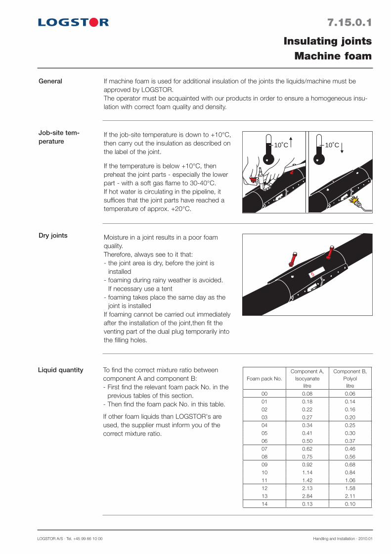
LOGSTOR A/S · Tel. +45 99 66 10 00 Handling and Installation · 2010.01
7.15.0.1
General
Job-site tem-perature
Dry joints
Insulating jointsMachine foam
If machine foam is used for additional insulation of the joints the liquids/machine must be approved by LOGSTOR.The operator must be acquainted with our products in order to ensure a homogeneous insu-lation with correct foam quality and density.
10˚C 10˚C
If the job-site temperature is down to +10°C, then carry out the insulation as described on the label of the joint.
If the temperature is below +10°C, then preheat the joint parts - especially the lower part - with a soft gas flame to 30-40°C.If hot water is circulating in the pipeline, it suffices that the joint parts have reached a temperature of approx. +20°C.
Moisture in a joint results in a poor foam quality.Therefore, always see to it that:- the joint area is dry, before the joint is
installed- foaming during rainy weather is avoided.
If necessary use a tent- foaming takes place the same day as the
joint is installedIf foaming cannot be carried out immediately after the installation of the joint,then fit the venting part of the dual plug temporarily into the filling holes.
To find the correct mixture ratio between component A and component B:- First find the relevant foam pack No. in the
previous tables of this section.- Then find the foam pack No. in this table.
If other foam liquids than LOGSTOR's are used, the supplier must inform you of the correct mixture ratio.
Liquid quantityFoam pack No.
Component A, Isocyanate
litre
Component B, Polyollitre
00 0.08 0.06
01 0.18 0.14
02 0.22 0.16
03 0.27 0.20
04 0.34 0.25
05 0.41 0.30
06 0.50 0.37
07 0.62 0.46
08 0.75 0.56
09 0.92 0.68
10 1.14 0.84
11 1.42 1.06
12 2.13 1.58
13 2.84 2.11
14 0.13 0.10

Handling and Installation · 2010.01 LOGSTOR Fredericia A/S · Tel. +45 76 23 30 00
7.15.0.2
Filling
Heated service pipes
Insulating jointsMachine foam
Insulation of joints on heated service pipes results in a quicker foaming process and a higher foam pressure, especially if the insulation is carried out on a hot summer day.
Under such working conditions the following measures are taken:1. When used the liquid temperature must not exceed 15°C. 2. The mixing foam liquids are quickly pressed down into the joint, as the foam has a shorter
reaction time in a heated joint. 3. Joints must be foamed 1 hour after installation at the latest in order to prevent the forma-
tion of condensed water on the inside of the fittings. Moisture in a joint will increase the foam pressure additionally and result in a poor foam quality.
4. The installation area is shielded against sun heating, especially in the summer.
Always inject the foam liquid into the lower filling hole of the joint.Make sure that the foam liquid does not get in touch with the service pipe when it is injected, in order to ensure a correct, homo-geneous foaming.
Fit the venting plugs into the filling holes after filling.

LOGSTOR A/S · Tel. +45 99 66 10 00 Handling and Installation · 2014.05
8.0.0.1
Introduction
Contents
Isolation valves and ventingOverview
This section describes where and how isolation valves and separate venting/draining can be installed in a pipe run.
Installing and operating isolation valves 8.1Implementing venting/draining 8.2


LOGSTOR A/S · Tel. +45 99 66 10 00 Handling and Installation · 2014.05
Installation
Draining
Maintenance
The pipe system can be drained through the valve on the draining arrangement.To ensure complete draining use a suction pipe and, if necessary, blow air through the sys-tem.
In principle the isolation valve is maintenance free. However, it is recommended to operate the spindle in connection with the frequent chamber checks to ensure that the valve always functions.Valves for venting and draining are available as rustproof ball valves.Equipment welded on to the valves (and old ball valves) must be protected against corrosion. Valves, spindle tops, and spindles should not be permanently under water.
The simplest way to make access chamber to the valves is to place a concrete chamber on two rows of foundation bricks.
This ensures the free expansion of the pipes and the spindle tops are kept free of sand.
The method shown can also be used for major dimensions, provided that the spindles are tilted to enable operation from the chamber opening.
8.1.0.1
Survey
Isolation valves and ventingInstalling and operating isolation valves
Isolation valves are installed as a part of the pipe system at any required point on the pipe run. Consequently, expensive, special concrete chambers are not necessary.
As regards the operation of isolation valves, see the homepage of the relevant supplier (the brand appears from the top of the valve).

Handling and Installation · 2014.05 LOGSTOR Fredericia A/S · Tel. +45 76 23 30 00
The cover The galvanized cover can be used in flooded areas. At periodic floodings the weight of the cover prevents water from penetrating into the spindle top and valve ends which might result in corrosion.The cover is not fixed, but simply placed over the spindle top or the venting/draining arrangements.Measurements: See the Product Catalogue 2.5.6.
8.1.0.2
Isolation valves and ventingInstalling and operating isolation valves
ød
H
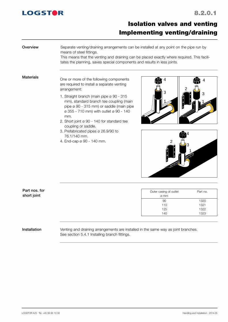
LOGSTOR A/S · Tel. +45 99 66 10 00 Handling and Installation · 2014.05
8.2.0.1
Overview
Materials
Installation
Isolation valves and ventingImplementing venting/draining
Separate venting/draining arrangements can be installed at any point on the pipe run by means of steel fittings.This means that the venting and draining can be placed exactly where required. This facili-tates the planning, saves special components and results in less joints.
Part nos. for short joint
Venting and draining arrangements are installed in the same way as joint branches.See section 5.4.1 Installing branch fittings.
90 1320 110 1321 125 1322 140 1323
Outer casing of outlet Part no. ø mm
One or more of the following components are required to install a separate venting arrangement:
1. Straight branch (main pipe ø 90 - 315 mm), standard branch tee coupling (main pipe ø 90 - 315 mm) or saddle (main pipe ø 355 - 710 mm) with outlet ø 90 - 140 mm.
2. Short joint ø 90 - 140 for standard tee coupling or saddle.
3. Prefabricated pipes ø 26.9/90 to 76.1/140 mm.
4. End-cap ø 90 - 140 mm.
4
31
2
4
3
1 1
3
4
2
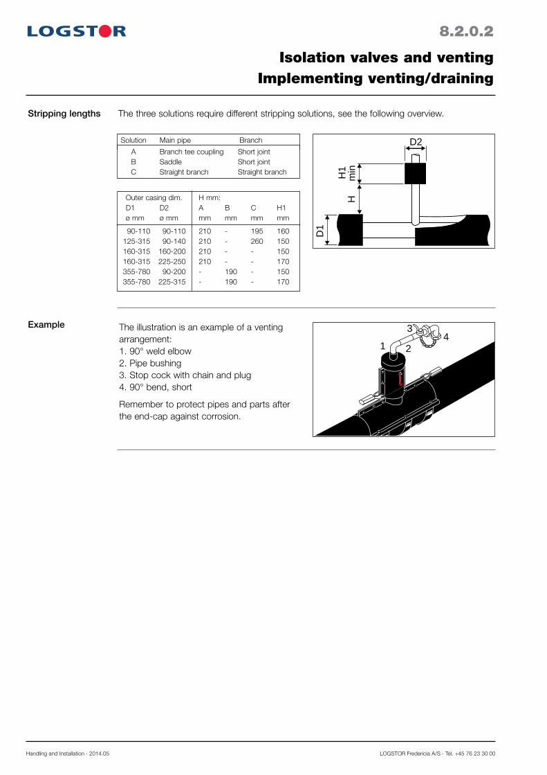
Handling and Installation · 2014.05 LOGSTOR Fredericia A/S · Tel. +45 76 23 30 00
Stripping lengths
Example
The three solutions require different stripping solutions, see the following overview.
Solution Main pipe Branch
A Branch tee coupling Short joint B Saddle Short joint C Straight branch Straight branch
1 2
34
D1
D2
H1
min
H
The illustration is an example of a venting arrangement:1. 90° weld elbow2. Pipe bushing3. Stop cock with chain and plug4. 90° bend, short
Remember to protect pipes and parts after the end-cap against corrosion.
Outer casing dim. H mm: D1 D2 A B C H1 ø mm ø mm mm mm mm mm
90-110 90-110 210 - 195 160 125-315 90-140 210 - 260 150 160-315 160-200 210 - - 150 160-315 225-250 210 - - 170 355-780 90-200 - 190 - 150 355-780 225-315 - 190 - 170
8.2.0.2
Isolation valves and ventingImplementing venting/draining

LOGSTOR A/S · Tel. +45 99 66 10 00 Handling and Installation · 2006.11
9.0.0.1
Introduction
Contents
ReductionsOverview
This section describes how to install reductions in the pipe system.
Installing reducing ring 9.1Installing preinsulated reduction 9.2Installing PE-shrink reduction 9.3

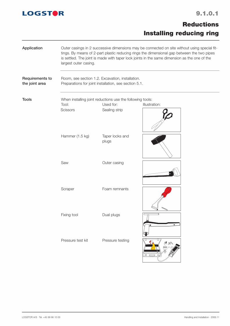
LOGSTOR A/S · Tel. +45 99 66 10 00 Handling and Installation · 2006.11
9.1.0.1
Application
Requirements to the joint area
Tools
ReductionsInstalling reducing ring
Outer casings in 2 successive dimensions may be connected on site without using special fit-tings. By means of 2-part plastic reducing rings the dimensional gap between the two pipes is settled. The joint is made with taper lock joints in the same dimension as the one of the largest outer casing.
Hammer (1.5 kg) Taper locks and plugs
Saw Outer casing
Scraper Foam remnants
Fixing tool Dual plugs
Pressure test kit Pressure testing
Room, see section 1.2. Excavation, installation.Preparations for joint installation, see section 5.1.
When installing joint reductions use the following tools: Tool: Used for: Illustration:Scissors Sealing strip
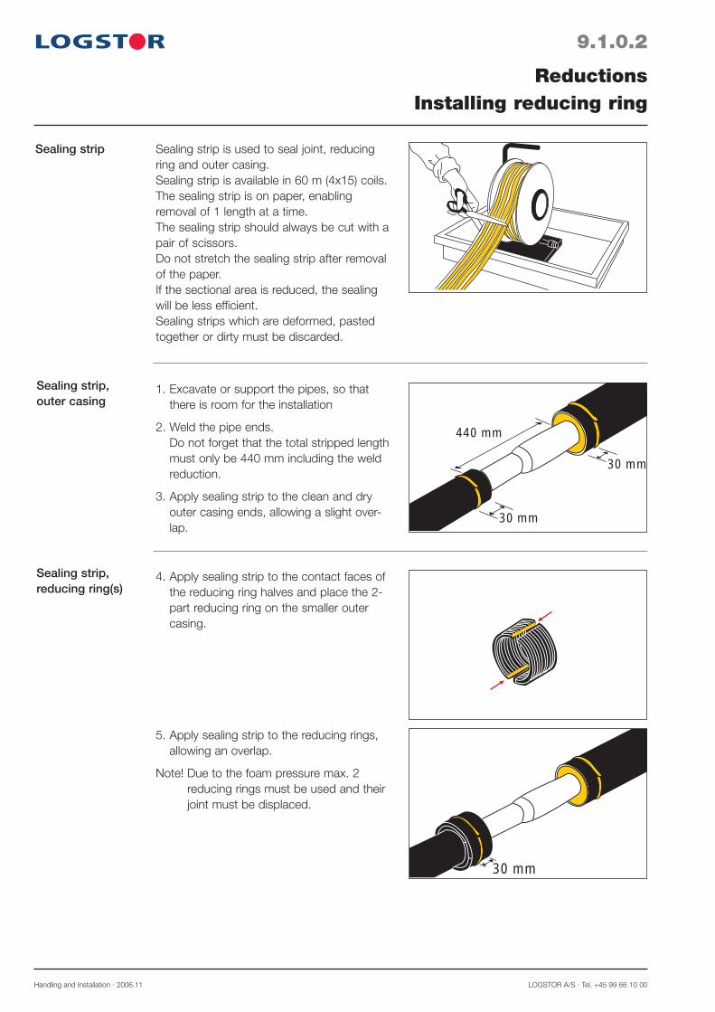
Handling and Installation · 2006.11 LOGSTOR A/S · Tel. +45 99 66 10 00
9.1.0.2
Sealing strip
ReductionsInstalling reducing ring
Sealing strip is used to seal joint, reducing ring and outer casing.Sealing strip is available in 60 m (4x15) coils.The sealing strip is on paper, enabling removal of 1 length at a time.The sealing strip should always be cut with a pair of scissors.Do not stretch the sealing strip after removal of the paper.If the sectional area is reduced, the sealing will be less efficient.Sealing strips which are deformed, pasted together or dirty must be discarded.
Sealing strip,outer casing
Sealing strip,reducing ring(s)
30 mm
30 mm
30 mm
440 mm
1. Excavate or support the pipes, so that there is room for the installation
2. Weld the pipe ends.Do not forget that the total stripped length must only be 440 mm including the weld reduction.
3. Apply sealing strip to the clean and dry outer casing ends, allowing a slight over-lap.
4. Apply sealing strip to the contact faces of the reducing ring halves and place the 2-part reducing ring on the smaller outercasing.
5. Apply sealing strip to the reducing rings, allowing an overlap.
Note! Due to the foam pressure max. 2 reducing rings must be used and their joint must be displaced.

LOGSTOR A/S · Tel. +45 99 66 10 00 Handling and Installation · 2006.11
9.1.0.3
Sealing strip,taper lock joint
ReductionsInstalling reducing rings
50 mm
6. Press the lower joint half up around the outer casing and support it.
7. Place the upper joint half into position and finish the joint.
See section 5.0 Installing joints, bends, and branches.
Up to and including ø 250 mm reductions are made in this way, whether it be a straight joint, a bend or a branch.Auxiliary tool, part no. 1732, facilitates the installation of taper locks.

Handling and Installation · 2006.11 LOGSTOR A/S · Tel. +45 99 66 10 00
9.2.0.1
Application
Installationmeasures
ReductionsInstalling preinsulated reduction
- Preinsulated reductions are concentric i.e. both dimensions are symmetric around the pipe axis.
- Note whether the preinsulated reduction is with 1 or 2 reduction steps, because it is impor-tant for the stress level in connection with certain installation methods.See drawing or contact the supervisor.
1500 mm
Preinsulated reductions are primarily used where it is dimensionally impossible to use the more simple system with reducing rings.
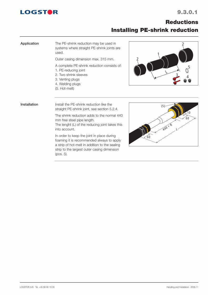
LOGSTOR A/S · Tel. +45 99 66 10 00 Handling and Installation · 2006.11
9.3.0.1
Application
ReductionsInstalling PE-shrink reduction
21
L3 4
2
5
The PE-shrink reduction may be used in systems where straight PE-shrink joints are used.
Outer casing dimension max. 315 mm.
A complete PE-shrink reduction consists of:1. PE-reducing joint2. Two shrink sleeves3. Venting plugs4. Welding plugs(5. Hot-melt)
Installation
60
10
440 + R
60
L
(5)Install the PE-shrink reduction like the straight PE-shrink joint, see section 5.2.4.
The shrink reduction adds to the normal 440 mm free steel pipe length.The lenght (L) of the reducing joint takes this into account.
In order to keep the joint in place during foaming it is recommended always to apply a strip of hot-melt in addition to the sealing strip to the largest outer casing dimension (pos. 5).


LOGSTOR A/S · Tel. +45 99 66 10 00 Handling and Installation · 2009.12
10.0.0.1
Introduction
Contents
Installing terminationsOverview
This section describes how to install different types of terminations in the pipe system.
Installing house entry pipes 10.1Installing wall entry sleeve 10.2Installing end-cap 10.3Installing termination pipe 10.4Installing end fittings with insulation shells ø 90 - 630 mm 10.5.1Installing end fittings for foaming ø 710 - 1000 mm 10.5.2

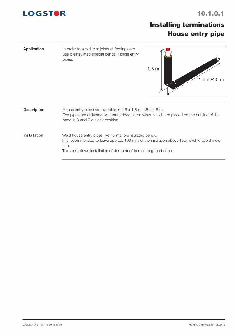
LOGSTOR A/S · Tel. +45 99 66 10 00 Handling and Installation · 2009.12
10.1.0.1
Application
Description
Installation
Installing terminationsHouse entry pipe
House entry pipes are available in 1.5 x 1.5 or 1.5 x 4.5 m.The pipes are delivered with embedded alarm wires, which are placed on the outside of the bend in 3 and 9 o’clock position.
Weld house entry pipes like normal preinsulated bends.It is recommended to leave approx. 100 mm of the insulation above floor level to avoid mois-ture. This also allows installation of dampproof barriers e.g. end-caps.
1.5 m
1.5 m/4.5 m
In order to avoid joint joints at footings etc. use preinsulated special bends: House entry pipes.
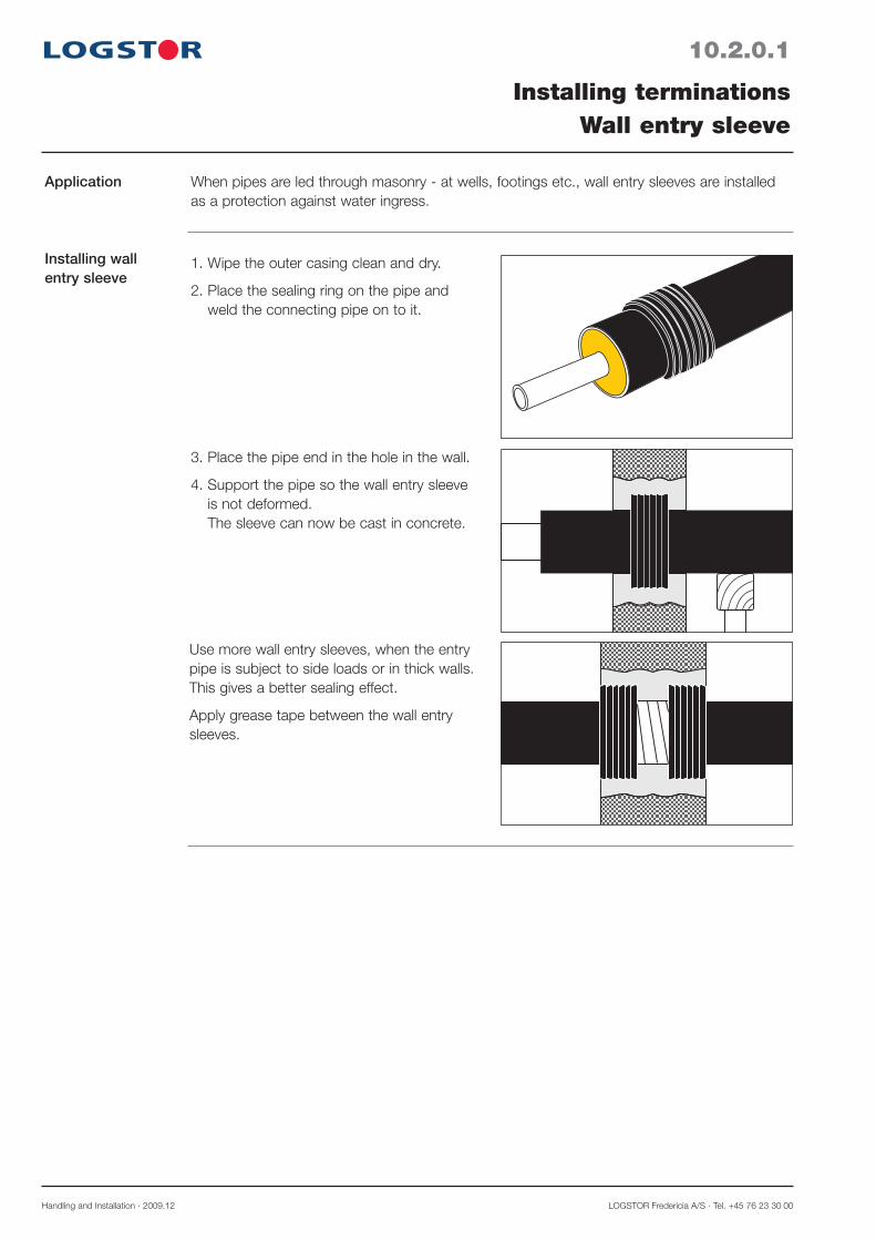
Handling and Installation · 2009.12 LOGSTOR Fredericia A/S · Tel. +45 76 23 30 00
10.2.0.1
Application
Installing wall entry sleeve
Installing terminationsWall entry sleeve
When pipes are led through masonry - at wells, footings etc., wall entry sleeves are installed as a protection against water ingress.
1. Wipe the outer casing clean and dry.
2. Place the sealing ring on the pipe and weld the connecting pipe on to it.
3. Place the pipe end in the hole in the wall.
4. Support the pipe so the wall entry sleeve is not deformed. The sleeve can now be cast in concrete.
Use more wall entry sleeves, when the entry pipe is subject to side loads or in thick walls. This gives a better sealing effect.
Apply grease tape between the wall entry sleeves.

LOGSTOR A/S · Tel. +45 99 66 10 00 Handling and Installation · 2009.12
10.3.0.1
Application
Preparations
Shrinkage
Installing terminationsEnd-cap
End-caps are used to seal the pipes to prevent moisture from penetrating into the foam insu-lation.
They are e.g. used at terminations in chambers, in connection with branch adaptors to con-crete ducts, in cellars etc.
1-2 min.
1. Wipe the outer casing and steel pipe clean and dry.
2. Grind the outer casing, using emery cloth, grain size 60, until the surface becomes mat. Also grind the steel pipe.
4. Use a soft gas flame for the shrinking. Important: Start with the part of the end-cap which is placed on the outer casing. When it has been shrunk, wait 1-2 min-utes, before shrinking the part on the steel pipe.
5. Carry out the shrinking on the steel pipe as shown in the drawings in order to avoid air pockets. Do not heat directly on the vertical part.
Do not heat the part on the outer casing dur-ing the final shrinking, as the end-cap might slide off the outer casing.
Max. temperature:After the installation the part of the end-cap on the steel pipe must not be exposed to more than 130° C.The part on the outer casing must not be exposed to more than 70° C.
3. Preheat outer casing and steel pipe to approx. 60° C. Protect the foam from direct flame con-tact. Centre the end-cap on the clean, preheat-ed pipe end.
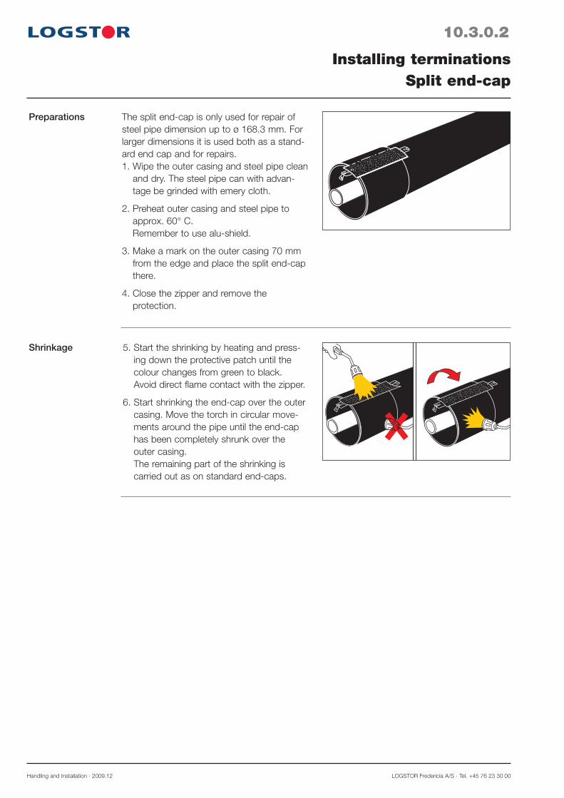
Handling and Installation · 2009.12 LOGSTOR Fredericia A/S · Tel. +45 76 23 30 00
10.3.0.2
Preparations
Shrinkage
Installing terminationsSplit end-cap
The split end-cap is only used for repair of steel pipe dimension up to ø 168.3 mm. For larger dimensions it is used both as a stand-ard end cap and for repairs.1. Wipe the outer casing and steel pipe clean
and dry. The steel pipe can with advan-tage be grinded with emery cloth.
2. Preheat outer casing and steel pipe to approx. 60° C. Remember to use alu-shield.
3. Make a mark on the outer casing 70 mm from the edge and place the split end-cap there.
4. Close the zipper and remove the protection.
5. Start the shrinking by heating and press-ing down the protective patch until the colour changes from green to black. Avoid direct flame contact with the zipper.
6. Start shrinking the end-cap over the outer casing. Move the torch in circular move-ments around the pipe until the end-cap has been completely shrunk over the outer casing. The remaining part of the shrinking is carried out as on standard end-caps.

LOGSTOR A/S · Tel. +45 99 66 10 00 Handling and Installation · 2009.12
10.4.0.1
Application
Preparations
Welding
Shrinking sleeve
Installing terminationsTermination pipe
Termination pipes are used to prevent moisture from penetrating into the foam insulation. They are used to terminate pipes in chambers, in connection with branch adaptors to concrete ducts, in cellars etc.
A
1-2 min.
1. Wipe the outer casing and steel pipe clean and dry.
2. Slide the termination pipe on to the pipe end. The insulation of the pipe must not touch the end of the termination pipe.
This can be prevented for pipes in dimen-sions ø 26.9 - 219.1 mm by placing the supplied 50 mm insulation sections of min-eral wool at the bottom of the termination pipe before sliding it on to the pipe end.
In connection with larger dimensions the correct distance , A = 100 mm, is marked.
3. Place grease tape around the outer cas-ing at the transition to the termination pipe.
4. Weld the termination pipe to the steel pipe. The pipe is now secure against water ingress and the termination pipe will also follow possible expansion movements.
5. Wipe the shrinking area clean and grind the outer casing with emery cloth, grain size 60. Preheat the shrinking area to 50-60°C.
6. Shrink the shrink sleeve with a soft gas flame.
Start with the part of the shrink sleeve on the termination pipe. When it has been shrunk, wait 1-2 min., before shrinking the outer casing.Now the pipe is completely safe against water ingress.
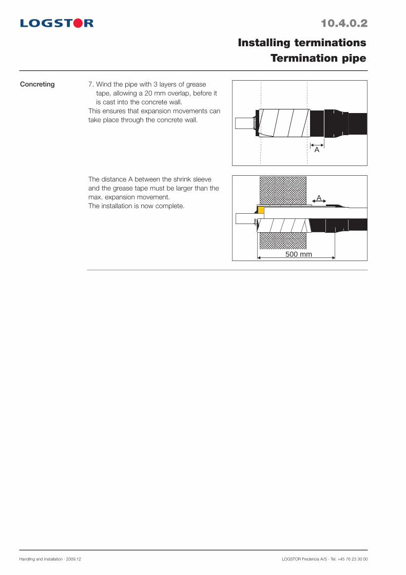
Handling and Installation · 2009.12 LOGSTOR Fredericia A/S · Tel. +45 76 23 30 00
10.4.0.2
Concreting
Installing terminationsTermination pipe
A
7. Wind the pipe with 3 layers of grease tape, allowing a 20 mm overlap, before it is cast into the concrete wall.
This ensures that expansion movements can take place through the concrete wall.
The distance A between the shrink sleeve and the grease tape must be larger than the max. expansion movement.The installation is now complete.
500 mm
A
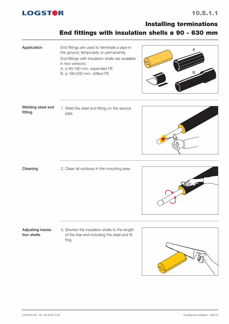
LOGSTOR A/S · Tel. +45 99 66 10 00 Handling and Installation · 2009.12
10.5.1.1
Application
Welding steel end fitting
Installing terminationsEnd fittings with insulation shells ø 90 - 630 mm
End fittings are used to terminate a pipe in the ground, temporarily or permanently.
End fittings with insulation shells are available in two versions: A. ø 90-160 mm, expanded PE B. ø 180-630 mm, drifted PE
1. Weld the steel end fitting on the service pipe.
2. Clean all surfaces in the mounting area.
3. Shorten the insulation shells to the length of the free end including the steel end fit-ting.
A
B
Cleaning
Adjusting insula-tion shells
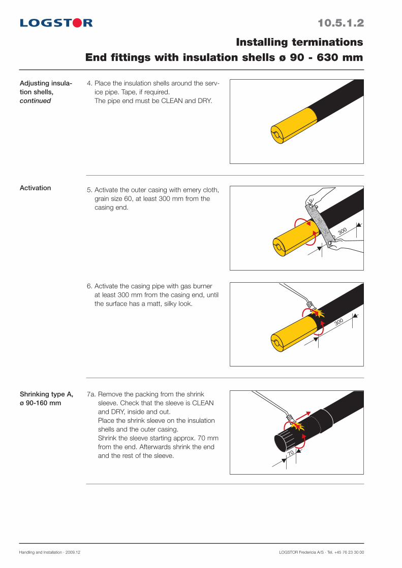
Handling and Installation · 2009.12 LOGSTOR Fredericia A/S · Tel. +45 76 23 30 00
10.5.1.2
Adjusting insula-tion shells, continued
Activation
Installing terminationsEnd fittings with insulation shells ø 90 - 630 mm
4. Place the insulation shells around the serv-ice pipe. Tape, if required. The pipe end must be CLEAN and DRY.
300
300
70
5. Activate the outer casing with emery cloth, grain size 60, at least 300 mm from the casing end.
6. Activate the casing pipe with gas burner at least 300 mm from the casing end, until the surface has a matt, silky look.
7a. Remove the packing from the shrink sleeve. Check that the sleeve is CLEAN and DRY, inside and out. Place the shrink sleeve on the insulation shells and the outer casing. Shrink the sleeve starting approx. 70 mm from the end. Afterwards shrink the end and the rest of the sleeve.
Shrinking type A,ø 90-160 mm
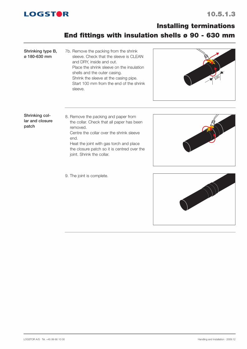
LOGSTOR A/S · Tel. +45 99 66 10 00 Handling and Installation · 2009.12
10.5.1.3
Shrinking type B,ø 180-630 mm
Shrinking col-lar and closure patch
Installing terminationsEnd fittings with insulation shells ø 90 - 630 mm
7b. Remove the packing from the shrink sleeve. Check that the sleeve is CLEAN and DRY, inside and out. Place the shrink sleeve on the insulation shells and the outer casing. Shrink the sleeve at the casing pipe. Start 100 mm from the end of the shrink sleeve.
8. Remove the packing and paper from the collar. Check that all paper has been removed. Centre the collar over the shrink sleeve end. Heat the joint with gas torch and place the closure patch so it is centred over the joint. Shrink the collar.
9. The joint is complete.
100

Handling and Installation · 2009.12 LOGSTOR Fredericia A/S · Tel. +45 76 23 30 00
10.5.2.1
Installing terminationsEnd fittings for foaming ø 710-1000 mm
Application
Preparing to shrink and foam-ing
End fittings for foaming are used to terminate pipes in dimensions ø 710-1000 mm.
100
See section 10.5.1 for:- welding steel end fitting and cleaning, p. 10.5.1.1.- activation, p. 10.5.1.2.
1. Remove the packing from the shrink sleeve. Check that the sleeve is CLEAN and DRY, inside and out. Place the shrink sleeve on the insulation shells and the outer casing. Shrink the sleeve, starting approx. 100 mm from the end.
2. Remove the packing and paper from the collar. Check that all paper has been removed. Centre the collar over the shrink sleeve end. Heat the joint with gas torch and place the closure patch so it is centred over the joint. Shrink the collar.
Shrinking sleeve and collar
3. Drill a hole (ø 25 mm) in the sleeve. Leakage test, if desired. Foam the sleeve. Install venting plugs in the hole. Wait at least 30 min. for degassing to complete. Remove the venting plug by turning and lifting it. Remove excess foam, if any. N.B. For size of foam packs, see section 7
Venting and filling hole

LOGSTOR A/S · Tel. +45 99 66 10 00 Handling and Installation · 2009.12
10.5.2.2
Installing terminationsEnd fittings for foaming ø 710 - 1000 mm
Expansion plugs 4. Remove the protective foil from the ex-pansion plugs and check the mastic. Activate briefly the recessed area with a hard flame. Mount the expansion plug in the hole and press until the mastic is spread smoothly under the collar of the plug.
5. Centre the wedge plug in the expansion plug and drive it completely into the plug with a hammer.
6. Place the patch on a patch-spoon or other fire resistant material, the hotmelt side facing up. Heat the hotmelt side until the mastic begins to bubble.
Wedge plug
Activate briefl y the recessed area with a hard fl ame. Place the patch over the plug in the recessed area, the hotmelt side facing down Press it at once hard with the patch-press for approx. 10 sec. The patch must fit tightly to the joint in the recessed area.If the patch does not fi t tightly or the co-lored spots, if any, of the patch do not turn black, it must be heated again for a short while with a hard fl ame and pressed with the patch-press for approx. 10 sec. The joint is complete.
Patch installation
20 sec.

LOGSTOR A/S · Tel. +45 99 66 10 00 Handling and Installation · 2008.01
11.0.0.1
Introduction
Contents
Installing FlexPipesOverview
This section contains a description of the preparations, adjustments, and connections etc. which are general for all FlexPipe types as well as specific for each FlexPipe type.
Installing special joints for FlexPipes 11.0.1
Installing FlexPipes, general 11.1
Installing compression fittings, AluFlex pipes 11.2.2
Installing soldering fittings, CuFlex pipes 11.2.3
Installing straight joints:General 11.3.0SteelFlex 11.3.1AluFlex 11.3.3CuFlex 11.3.4
Connection to main pipe:General 11.4.0Hot tapping 11.4.1SteelFlex 11.4.2AluFlex 11.4.4CuFlex 11.4.5
Terminations, general 11.5.


LOGSTOR A/S · Tel. +45 99 66 10 00 Handling and Installation · 2008.01
11.0.1.0
Introduction
Contents
FlexPipesInstalling special joints for FlexPipes
This section, 11.0.1-5, contains installation instructions for joints, exclusively made for FlexPipe systems.
References to joints which are common with straight pipe systems are listed below.
FX-joints 11.0.2C2L-joints 11.0.3C2F-joints 11.0.4T-joints straight F 11.0.5
References Straight joints:- Taper lock joints, band joints, SX-joints 5.2
Branches:- Steel joint branches (straight, 45°, 90°, branch saddle)
Band joint branches, SXT-branches, T2S-branches 5.4

Handling and Installation · 2008.01 LOGSTOR Fredericia A/S · Tel. +45 76 23 30 00
11.0.2.1
FlexPipesInstalling FX joints
FX joint set 1. Insulation shells2. Flexible insulation shells3. Shrink sleeve4. Mastic tape5. Tissue
1
2
3
4 5
1. CouplingCut off the insulation with suitable stripping tool. L depends on the type of coupling. Install the coupling as shown in the relevant instructions.
2. Place the shrink sleeve with packing on one of the pipes a, before the service pipes are joined b.
Important:
Avoid heating directly on creases, otherwise it may cause damages on the surface of the sleeve.
Avoid heating in between the sleeve and the casing, otherwise the sleeve may be damaged permanently.
Use burner head ø51 mm for sleeves up to ø200 mm. For larger sleeves use burner head ø63 mm.
a
b
L
Installationinstructions
3. Clean all surfaces in the mounting area.

LOGSTOR A/S · Tel. +45 99 66 10 00 Handling and Installation · 2008.01
11.0.2.2
FlexPipesInstalling FX joints
Installation instructions,continued
4. Shorten the insulation shells to size, so that they fi t tightly between the casing pipes. As for couplings, it may prove necessary to cut away insulation foam from the coupling.
6. Activate the casing pipes with a gas burner at least 150 mm from both casing ends, until the surface has a matt, silky look.
7. Remove the packing from the shrink sleeve. Check that the sleeve is CLEAN and DRY inside and out. Centre the shrink sleeve over the joint and mark the position. Pull the shrink sleeve away.
5. Fit the insulation shells tightly between the casing pipes, using adhesive tape if neces-sary. Reduction: See at the end of this instruction. All surfaces must be CLEAN and DRY. Activate the casing pipes with abrasive cloth grain size 60 at least 150 mm from both casing ends.
8. Remove the protective foil from one side of the mastic tape and mount them on the casing pipes approx. 30 mm within the markings. Press the tape ends together. Remove the rest of the protective foil from the mastic tape. Centre the shrink sleeve between the markings.

Handling and Installation · 2008.01 LOGSTOR Fredericia A/S · Tel. +45 76 23 30 00
11.0.2.3
FlexPipesInstalling FX joints
Installation instructions,continued
9. Shrink the sleeve from the middle towards the ends Avoid heating directly on the cas-ing.
9a
9b
9c
A B
11. The joint is complete.
10. Shrink until the expansion marks have disappeared in particular over the mastic tape and the sleeve end forms an almost straight edge all the way around.
A. Before B. After
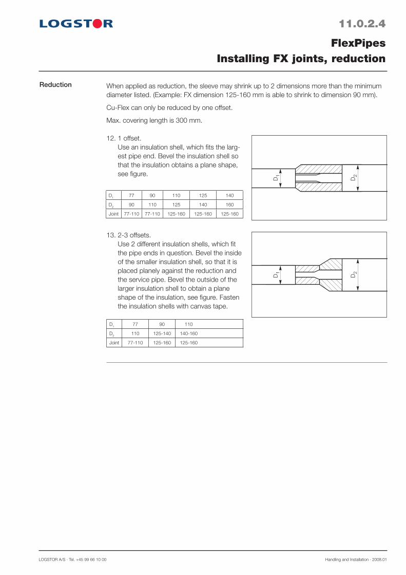
LOGSTOR A/S · Tel. +45 99 66 10 00 Handling and Installation · 2008.01
11.0.2.4
FlexPipesInstalling FX joints, reduction
Reduction
13. 2-3 offsets.Use 2 different insulation shells, which fi t the pipe ends in question. Bevel the inside of the smaller insulation shell, so that it is placed planely against the reduction and the service pipe. Bevel the outside of the larger insulation shell to obtain a plane shape of the insulation, see fi gure. Fasten the insulation shells with canvas tape.
12. 1 offset.Use an insulation shell, which fi ts the larg-est pipe end. Bevel the insulation shell so that the insulation obtains a plane shape, see fi gure.
When applied as reduction, the sleeve may shrink up to 2 dimensions more than the minimum diameter listed. (Example: FX dimension 125-160 mm is able to shrink to dimension 90 mm).
Cu-Flex can only be reduced by one offset.
Max. covering length is 300 mm.
D1 77 90 110 125 140
D2 90 110 125 140 160
Joint 77-110 77-110 125-160 125-160 125-160
D1 77 90 110
D2 110 125-140 140-160
Joint 77-110 125-160 125-160

Handling and Installation · 2008.01 LOGSTOR Fredericia A/S · Tel. +45 76 23 30 00
11.0.3.1
FlexPipesInstalling C2L joints
C2L joint set 1. Insulation shells2. Shrink film3. Shrink sleeve4. Shrink wrap5. Closure patch6. Tissue 1
2
3
4
5
5
6
1. Mount the service pipes. Clean all surfaces in the mounting area.
2. Shorten the insulation shells to make them fi t tightly between the casing pipes.
3. Fit the insulation shells tightly between the casing pipes, using adhesive tape if required. All surfaces must be CLEAN and DRY.
Installationinstructions

LOGSTOR A/S · Tel. +45 99 66 10 00 Handling and Installation · 2008.01
11.0.3.2
FlexPipesInstalling C2L joints
Installationinstructions,continued
4. Activate the casing pipes with abrasive cloth grain size 60 at least 150 mm from both pipe ends.
5. Activate the casing pipes with gas burner at least 150 mm from both pipe ends, until the surface has a matt, silky look.
6. Place the shrink fi lm so that the marking line forms a ring around the pipe. At-tach one edge of the shrink fi lm in the "10 o’clock" position. Pull the fi lm around the pipe by removing the adhesive paper so that the fi lm adheres to the surface beneath it.
8. Make sure that the sleeve is CLEAN and DRY. Clean all surfaces in the mounting area. Centre the shrink sleeve on the joint. Check that it is correctly positioned. The cut must be on the top and the edges must rest against each other. Fix with adhesive tape if required.
7. Heat the whole fi lm from the centre to-wards the sides, ensuring that the mastic becomes visible at all edges and that the shrink fi lm is tightly fi tted.

Handling and Installation · 2008.01 LOGSTOR Fredericia A/S · Tel. +45 76 23 30 00
11.0.3.3
FlexPipesInstalling C2L joints
Installationinstructions,continued
9. Centre the closure patch on the shrink sleeve cut with the hotmelt facing down-wards. The side with the hotmelt has vis-ible reinforcement. Heat the closure patch until the structure of reinforcement be-comes visible on the topside. Press down the closure patch.
10. Turn the sleeve 90°, so that the closure patch is in a "3 o'clock position". Shrink the sleeve from the centre towards the ends.
11. Remove the paper, while pulling the wrap into position, ensuring that the marking goes around the pipe and closes at the top. The wrap must fi t loosely around the pipe.
12. Centre the closure patch right above the wrap seam. Fasten as described under 10.
13. Shrink the wrap from the centre towards the ends. Shrink until the mastic be-comes visible at all edges and the full shrinking effect has been utilised.

LOGSTOR A/S · Tel. +45 99 66 10 00 Handling and Installation · 2008.01
11.0.3.4
FlexPipesInstalling C2L joints
Installationinstructions,continued
14. Roll along the overlapping edge, ensuring that any tunnel at the edge is sealed with mastic.The joint is complete.

Handling and Installation · 2008.01 LOGSTOR Fredericia A/S · Tel. +45 76 23 30 00
11.0.4.1
FlexPipesInstalling C2F joints
C2F joint set 1. Insulation shells2. Shrink film3. Shrink sleeve4. Shrink wrap5. Closure patch6. Tissue 1
2
3
4
56
5
1. Cut off the insulation with suitable stripping tool. L depends on the type of coupling.
2. Install the coupling as shown in the relevant instructions.
3. Clean all surfaces in the mounting area.
L
Installationinstructions
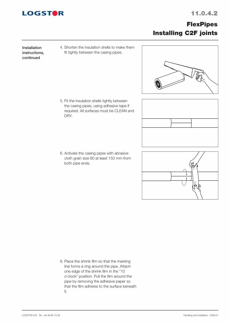
LOGSTOR A/S · Tel. +45 99 66 10 00 Handling and Installation · 2008.01
11.0.4.2
FlexPipesInstalling C2F joints
Installationinstructions,continued
4. Shorten the insulation shells to make them fi t tightly between the casing pipes.
6. Activate the casing pipes with abrasive cloth grain size 60 at least 150 mm from both pipe ends.
5. Fit the insulation shells tightly between the casing pipes, using adhesive tape if required. All surfaces must be CLEAN and DRY.
8. Place the shrink fi lm so that the marking line forms a ring around the pipe. Attach one edge of the shrink fi lm in the "10 o’clock" position. Pull the fi lm around the pipe by removing the adhesive paper so that the fi lm adheres to the surface beneath it.
7. Activate the casing pipes with gas burner at least 150 mm from both pipe ends, until the surface has a matt, silky look.

Handling and Installation · 2008.01 LOGSTOR Fredericia A/S · Tel. +45 76 23 30 00
11.0.4.3
FlexPipesInstalling C2F joints
Installationinstructions,continued
9. Heat the whole fi lm from the centre to-wards the sides, ensuring that the mastic becomes visible at all edges and that the shrink fi lm is tightly fi tted.
10. Make sure that the sleeve is CLEAN and DRY. Clean all surfaces in the mount-ing area. Centre the shrink sleeve on the joint. Check that it is correctly positioned. The cut must be on the top and the edges must rest against each other. Fix with adhesive tape if required.
11. Centre the closure patch on the shrink sleeve cut with the hotmelt facing down-wards. The side with the hotmelt has visible reinforcement. Heat the closure patch until the structure of reinforcement becomes visible on the topside. Press down the closure patch.
12. Turn the sleeve 90°, so that the closure patch is in a "3 o'clock position". Shrink the sleeve from the centre towards the ends.
13. Remove the paper, while pulling the wrap into position, ensuring that the marking goes around the pipe and closes at the top. The wrap must fi t loosely around the pipe.

LOGSTOR A/S · Tel. +45 99 66 10 00 Handling and Installation · 2008.01
11.0.4.4
FlexPipesInstalling C2F joints
Installationinstructions,continued
14. Centre the closure patch right above the wrap seam. Fasten as described under 11.
15. Shrink the wrap from the centre towards the ends. Shrink until the mastic be-comes visible at all edges and the full shrinking effect has been utilised.
17. The joint is complete.
16. Roll along the overlapping edge, ensur-ing that any tunnel at the edge is sealed with mastic.

Handling and Installation · 2008.01 LOGSTOR Fredericia A/S · Tel. +45 76 23 30 00
T-joint straight F set
11.0.5.1
FlexPipesT-joint straight F
1. Closure patch2. Shrink wrap3. Insulation shells4. T-shoe5. Insulation shells6. Collar7. Tissue
Note!Not used for CuFlex
12
34
56
7
4. Shorten the insulation shells to make them fi t tightly between the casing pipes. It can be neces-sary to remove insulation foam around the coupling.
1. Cut off the insulation with suitable stripping tool. L depends on the type of coupling.
2. Place the collar, wrap and T-shoe on the branch line. Install the coupling according to actual instructions.
3. Clean all surfaces in the mounting area.
L
Installationinstructions

LOGSTOR A/S · Tel. +45 99 66 10 00 Handling and Installation · 2008.01
11.0.5.2
FlexPipesT-joint straight F
5. Fit the insulation shells tightly between the casing pipes, using adhesive tape if required. All surfaces must be CLEAN and DRY.
6. Heat the T-shoe to 50-60°C. Pull the T-shoe over the main pipe and fasten with tape.
Installationinstructions,continued
8. Activate the casing pipes with gas burner at least 150 mm from the casing ends, until the surface has a matt, silky look.
7. Activate the casing pipes with abrasive cloth grain size 60 at least 150 mm from the casing ends.
9. Remove the paper, while pulling the wrap into position. Turn the wrap so that the text goes around the pipe and closes at the top.

Handling and Installation · 2008.01 LOGSTOR Fredericia A/S · Tel. +45 76 23 30 00
11.0.5.3
FlexPipesT-joint straight F
10. Centre the closure patch on the wrap joint with the hotmelt facing down. The side with the hotmelt has visible reinforcement. Heat the closure patch until the structure of reinforcement becomes visible on the topside. Press down the closure patch.
Installationinstructions,continued
13. Shrink the outermost 200 mm on the branch of the T-shoe. Activate the casing 150 mm onto the branch.
200
11. Shrink the wrap from the centre towards both ends ensuring that the mastic becomes visible at both ends and the full shrinking effect has been utilised.
12. Roll along the overlapping edge, ensuring that any tunnel at the edge is sealed with mastic.
14. Remove the packing and paper from the collar. Check that the paper has been removed. Shrink while centering the collar on the end of the T-shoe.The joint is complete.

LOGSTOR A/S · Tel. +45 99 66 10 00 Handling and Installation · 2006.11
11.1.0.1
Installationmethods
Connection to main pipe
FlexPipesInstallation, general
B
Min 150mm + 2 D
B50 mm
50 mm
50 mm
50 mm
50 mm
50 mm
50 mm
5050
50
D
D
D
D
D
D
Min100mm+ D
A2 A1
B2m
FlexPipes are installed by utilization of tunnel-ling techniques or in trenches either horizon-tally or vertically in accordance with the mini-mum trench dimensions in the illustration.
The pipes must be surrounded by 50 mm stonefree backfill material, when installed in trenches.
A1 = Min. 300 mm with no traffic loadA2 = Min. 400 mm with traffic loadB = Warning tape
At directional changes the corners of the trench are curved to a minimum radius of 0.5 - 0.8 m, dependent on the dimension.
The best way to obtain a faultfree installation of service pipe connections and steel fit-tings is to have the FlexPipe ends completely straightened out prior to installation.
Straightening out the ends is done most easily before the requested length is cut off the FlexPipe coil.To provide room for later installation of compression couplings, min. 2 m of the house entry trench must remain uncovered in the case of perpendicular connection to a main pipe.B = min. length of straightened FlexPipe end = 2 m + min. trench width.
Parallel connection to main pipe.To provide sufficient space, FlexPipes installed by tunnelling must always be installed parallel to the main pipe.B = min. length of straightened FlexPipe = 2 m + min. trench width.

Handling and Installation · 2006.11 LOGSTOR A/S · Tel. +45 99 66 10 00
11.1.0.2
Termination in house
FlexPipesInstallation, general
For house connections through a cast inlet pipe or straight/tilted bore in the base make sure that the FlexPipe is led through the base in the same working process as installation and backfilling.
Therefore, the bore in the base is carried out simultaneously with or prior to the pipe installation.
Straight lead-in, pipe ends inside
Tilted lead-in.For the installation in the building a bare pipe end of min. 500 mm is required.
Bore in the base
yyyyyyyyyyyyyyyyyyyyyyyy
Min
. 500
77 100 110 90 120 125
yyyyyyyyyyyy
Min. 500
yyyyyyyyyyyyyyy
Min
. 500
Outer casing Hole diameter min. with sealing ring ø out. mm ø mm ø mm
For the installation in the building a bare pipe end of min. 500 mm is required.
The bore diameters in the table are recom-mended for bore in the base.
Tilted lead-in by means of a bore
Cast inlet pipe.For the installation in the building a pipe end of min. 500 mm is required.
Lead-in by means of an inlet pipe
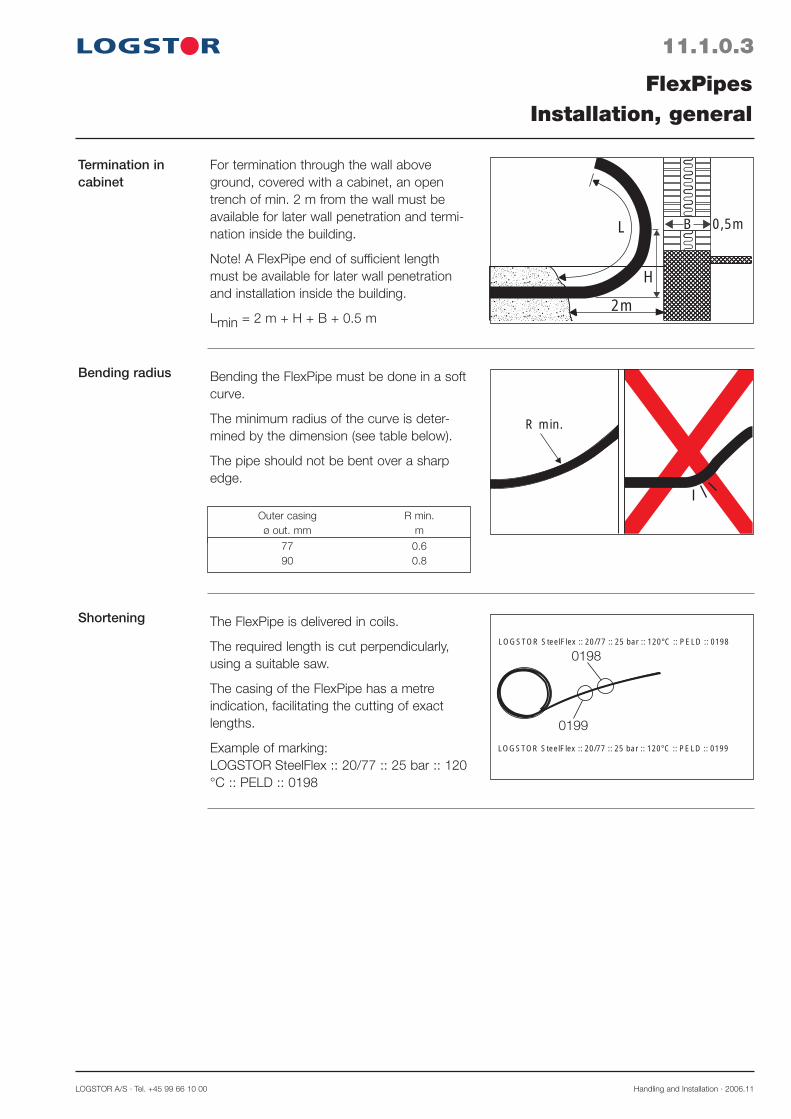
LOGSTOR A/S · Tel. +45 99 66 10 00 Handling and Installation · 2006.11
11.1.0.3
Termination in cabinet
Bending radius
Shortening
FlexPipesInstallation, general
R min.
yyyyyyyyy
2m
L B
H
0,5m
Bending the FlexPipe must be done in a soft curve.
The minimum radius of the curve is deter-mined by the dimension (see table below).
The pipe should not be bent over a sharp edge.
For termination through the wall above ground, covered with a cabinet, an open trench of min. 2 m from the wall must be available for later wall penetration and termi-nation inside the building.
Note! A FlexPipe end of sufficient length must be available for later wall penetration and installation inside the building.
Lmin = 2 m + H + B + 0.5 m
Outer casing R min. ø out. mm m
The FlexPipe is delivered in coils.
The required length is cut perpendicularly, using a suitable saw.
The casing of the FlexPipe has a metre indication, facilitating the cutting of exact lengths.
Example of marking:LOGSTOR SteelFlex :: 20/77 :: 25 bar :: 120 °C :: PELD :: 0198
77 0.6 90 0.8
LOGSTOR SteelFlex :: 20/77 :: 25 bar :: 120°C :: PELD :: 0198
LOGSTOR SteelFlex :: 20/77 :: 25 bar :: 120°C :: PELD :: 0199
0198
0199
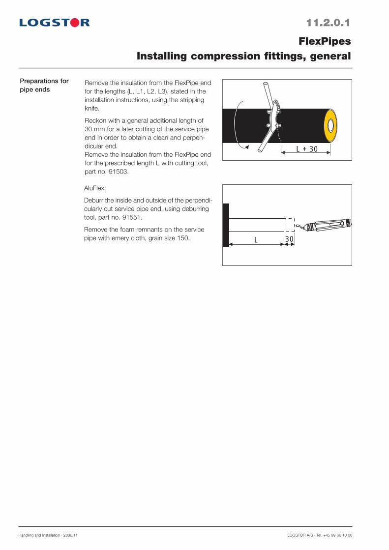
Handling and Installation · 2006.11 LOGSTOR A/S · Tel. +45 99 66 10 00
11.2.0.1
Preparations for pipe ends
FlexPipesInstalling compression fittings, general
L 30
L + 30
Remove the insulation from the FlexPipe end for the lengths (L, L1, L2, L3), stated in the installation instructions, using the stripping knife.
Reckon with a general additional length of 30 mm for a later cutting of the service pipe end in order to obtain a clean and perpen-dicular end.Remove the insulation from the FlexPipe end for the prescribed length L with cutting tool, part no. 91503.
AluFlex:
Deburr the inside and outside of the perpendi-cularly cut service pipe end, using deburring tool, part no. 91551.
Remove the foam remnants on the service pipe with emery cloth, grain size 150.

LOGSTOR A/S · Tel. +45 99 66 10 00 Handling and Installation · 2006.11
11.2.1.1
PexFlex DH pipesOverview
Catalogue pages A temporary reference is made to the Løgstør Catalogue:
Section 6.1 Design6.2 Components6.3 Installation


Alternatively compression toolfor service pipe dim. ø 20 - 32 mm
Complete tool set in carrying case with all necessary tools and accessories for service pipe dimensions ø 20, 26 and 32 mm. Part no. 18266.
Contents:1. Compression tool, complete with adapter,
incl. battery.2. Battery charger (230 V) incl. battery3. Exchangeable compression inserts4. Hacksaw5. Stripping knife6. Pipe cutter7. Deburring tool, internal8. Deburring tool, external9. Bending springs
2
47
8
9
3
1
56
LOGSTOR A/S · Tel. +45 99 66 10 00 Handling and Installation · 2006.11
11.2.2.1
AluFlex pipesInstalling compression fittings
AluFlex, com-pression cou-plings
Tools
1
2
3
4
6 7
8
5
112
A B
2 33
1
2
The AluFlex service pipe is joined by means of compression couplings, ensuring a per-manent tightness of all joints made at all temperature variations.
1. Base unit2. Compression ring3. Squeezing ring
A. Weld couplingB. Straight coupling
Hydraulic pump:Carrying case, part no. 91630Compression couplings are fitted with com-pression tools, activated by means of a hydraulic pump.The tools and accessories are delivered in sturdy carrying cases, containing the follow-ing:1. Hydraulic pump, complete2. Bottle with reserve oil, part no. 91571
Compression tool:Service pipe dimensions ø 20, ø 26, ø 32 and 40 mm.Carrying case, complete with contents, part no. 916811. Compression tool2. Exchangeable compression inserts3. Hacksaw4. Stripping knife5. Deburring tool, internal6. Deburring tool, external7. Special lubricating agent

Handling and Installation · 2006.11 LOGSTOR A/S · Tel. +45 99 66 10 00
11.2.2.2
AluFlex pipesInstalling compression fittings
Preparing first pipe end
Preparing second pipe end
1
Push the compression ring and the squeez-ing ring on to one of the pipe ends.
Push the compression ring and the squeez-ing ring on to the other pipe end.
Thrust the base unit into the pipe to stop.
Make sure that the insulating ring (1) is placed correctly.
Push the other pipe end on to the base unit to stop.
Make sure that the insulating ring (1) is placed correctly.

LOGSTOR A/S · Tel. +45 99 66 10 00 Handling and Installation · 2006.11
11.2.2.3
AluFlex pipesInstalling compression fittings
Preparing com-pression tool
Connecting hydraulic pump
2
1
Fit compression inserts, corresponding to the service pipe dimension, on to the com-pression tool.
Connect the hydraulic pump to the com-pression tool.1. Stop, hydraulic hose coupling2. Pull the locking ring back
Place the pipe joint in the compression tool. Prior to compression make sure that the joint is placed correctly.
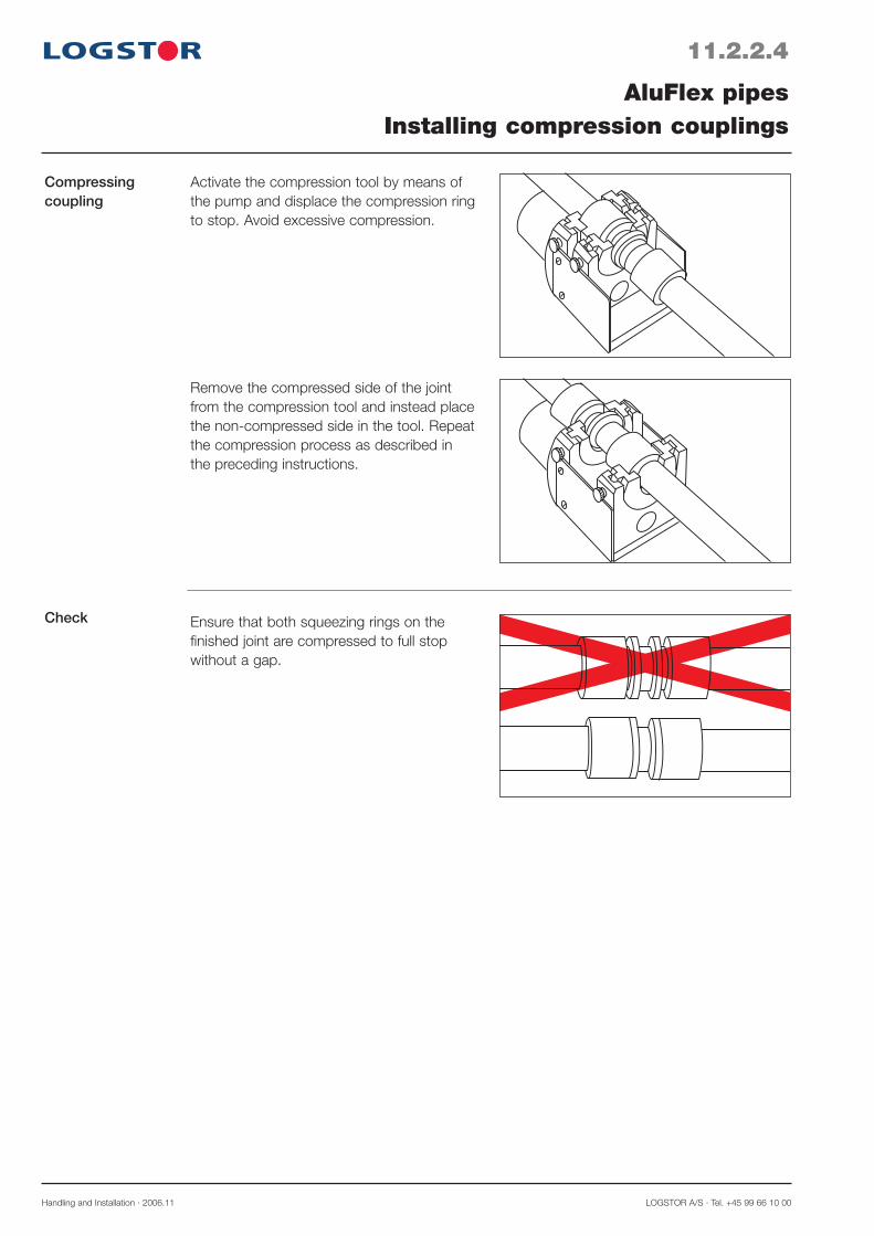
Handling and Installation · 2006.11 LOGSTOR A/S · Tel. +45 99 66 10 00
Compressing coupling
Activate the compression tool by means of the pump and displace the compression ring to stop. Avoid excessive compression.
Remove the compressed side of the joint from the compression tool and instead place the non-compressed side in the tool. Repeat the compression process as described in the preceding instructions.
11.2.2.4
AluFlex pipesInstalling compression couplings
Check Ensure that both squeezing rings on the finished joint are compressed to full stop without a gap.
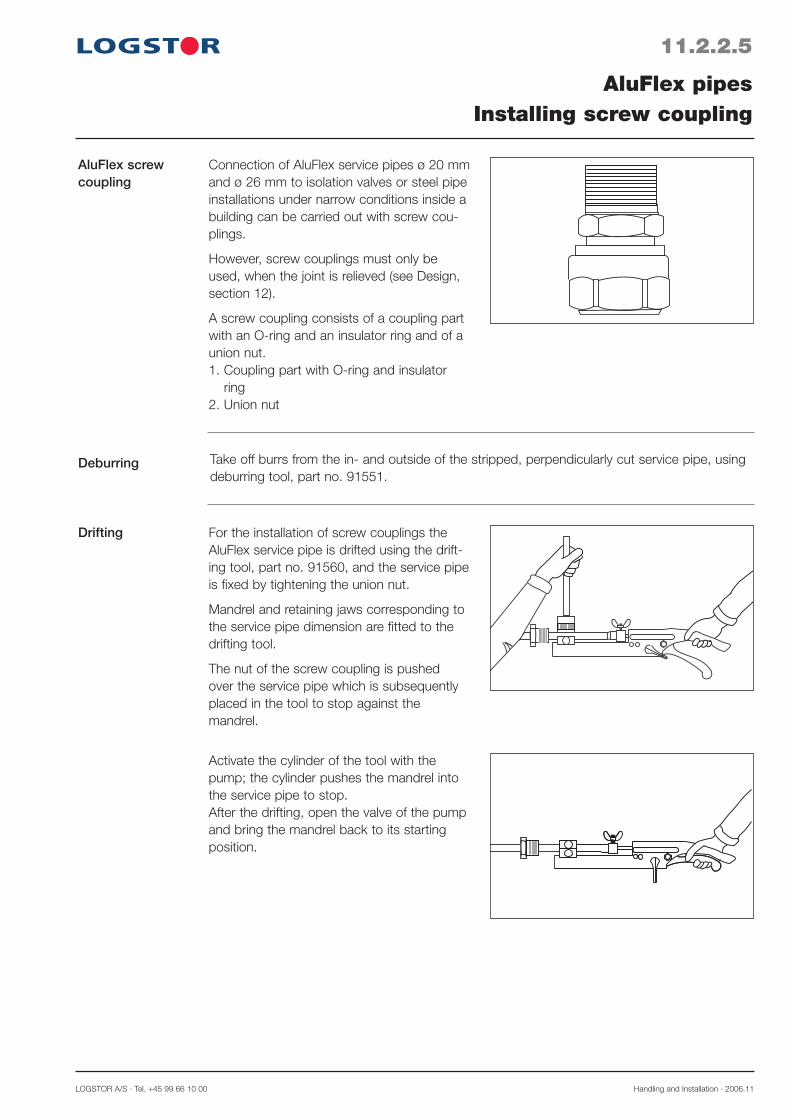
LOGSTOR A/S · Tel. +45 99 66 10 00 Handling and Installation · 2006.11
11.2.2.5
AluFlex screw coupling
Deburring
Drifting
AluFlex pipesInstalling screw coupling
Take off burrs from the in- and outside of the stripped, perpendicularly cut service pipe, using deburring tool, part no. 91551.
Connection of AluFlex service pipes ø 20 mm and ø 26 mm to isolation valves or steel pipe installations under narrow conditions inside a building can be carried out with screw cou-plings.
However, screw couplings must only be used, when the joint is relieved (see Design, section 12).
A screw coupling consists of a coupling part with an O-ring and an insulator ring and of a union nut.1. Coupling part with O-ring and insulator
ring2. Union nut
For the installation of screw couplings the AluFlex service pipe is drifted using the drift-ing tool, part no. 91560, and the service pipe is fixed by tightening the union nut.
Mandrel and retaining jaws corresponding to the service pipe dimension are fitted to the drifting tool.
The nut of the screw coupling is pushed over the service pipe which is subsequently placed in the tool to stop against the mandrel.
Activate the cylinder of the tool with the pump; the cylinder pushes the mandrel into the service pipe to stop.After the drifting, open the valve of the pump and bring the mandrel back to its starting position.
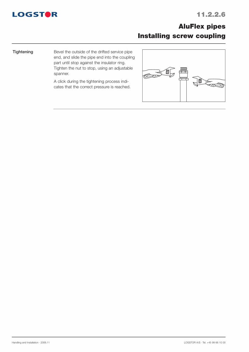
Handling and Installation · 2006.11 LOGSTOR A/S · Tel. +45 99 66 10 00
Tightening
11.2.2.6
AluFlex pipesInstalling screw coupling
Bevel the outside of the drifted service pipe end, and slide the pipe end into the coupling part until stop against the insulator ring. Tighten the nut to stop, using an adjustable spanner.
A click during the tightening process indi-cates that the correct pressure is reached.

LOGSTOR A/S · Tel. +45 99 66 10 00 Handling and Installation · 2006.11
11.2.3.1
CuFlex soldering fittings
Preparing the sol-dering
Calibration
CuFlex pipesInstalling soldering fittings
CuFlex pipes are joined by means of special soldering fittings with extra wall thickness and/or adjusted to the CuFlex pipe system.
1. Carry out the (perpendicular) shortening with a hacksaw
2. Clean the pipes carefully and remove any foam remnants
3. Remove any in- or external burrs with a file or special tool
4. Polish the inside of the soldering fitting and the outside of the copper pipe until they shine with an emery cloth.
The service pipe end is calibrated with a calibration tool.
Part nos.: ø 18 mm 3511ø 22 mm 3512ø 28 mm 3513
Place the calibration ring on the pipe end and hit it to stop against the pipe end.
Hit the mandrel to full stop against the ring.
Check that the pipe end and soldering fitting fit.
L

Handling and Installation · 2006.11 LOGSTOR A/S · Tel. +45 99 66 10 00
11.2.3.2
CuFlex pipesInstalling soldering fittings
Soldering crack
0.05-0.20 mm
3-5 x s s
The insertion depth must be 3-5 x wall thick-ness of the copper wire and the crack must be 0.05-0.20 mm.
Max. shearing strength at approx. 0,1 mm crack.
Soldering 1. Make sure that the soldering surfaces are still clean.
2. Place the soldering fitting correctly above the pipe end (to full stop).
3. Heat the joint evenly with a steady flame to 645 - 730 °C.
4. When the soldering temperature has been reached, soldering material is added to the joint and the heat supply is continued.
5. When the soldering material flows, the temperature on the joint is kept for another seconds, before the flame is removed.
Carry out the heating so the soldering material flows after approx. 40 seconds. This ensures that the soldering crack is completely filled.
6. After the joint has cooled brush the sol-dered point with a steel brush.
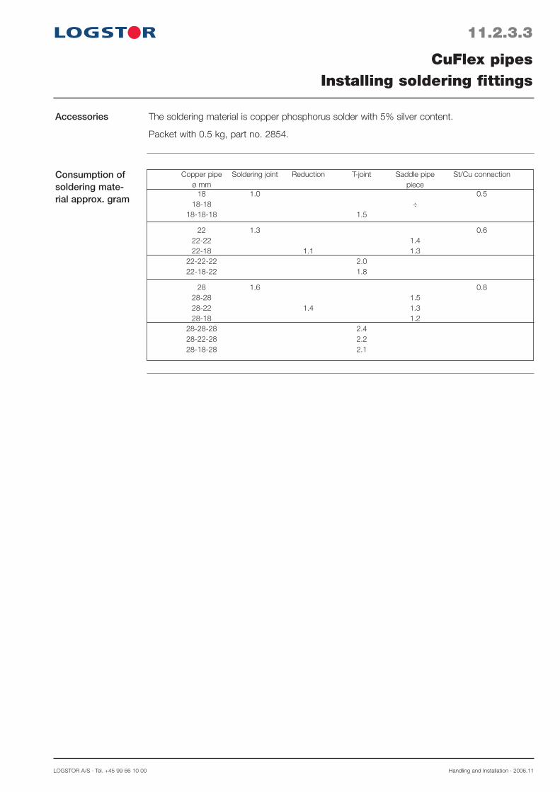
LOGSTOR A/S · Tel. +45 99 66 10 00 Handling and Installation · 2006.11
11.2.3.3
CuFlex pipesInstalling soldering fittings
Accessories The soldering material is copper phosphorus solder with 5% silver content.
Packet with 0.5 kg, part no. 2854.
Consumption of soldering mate-rial approx. gram
Copper pipe Soldering joint Reduction T-joint Saddle pipe St/Cu connection ø mm piece 18 1.0 0.5 18-18 ÷ 18-18-18 1.5
22 1.3 0.6 22-22 1.4 22-18 1.1 1.3 22-22-22 2.0 22-18-22 1.8
28 1.6 0.8 28-28 1.5 28-22 1.4 1.3 28-18 1.2 28-28-28 2.4 28-22-28 2.2 28-18-28 2.1

Insulating straight joints
Insulate the straight joints, using taper lock joints, possibly reducing rings as well as foam pack.
Handling and Installation · 2006.11 LOGSTOR A/S · Tel. +45 99 66 10 00
11.3.0.1
Types of joints
FlexPipesInstalling straight joints, general
There are in principle 3 different types of straight joint in connection with FlexPipes:- Straight joints of the same dimension- Reduction between two FlexPipes of different dimension- Connection from FlexPipe to ordinary preinsulated pipeThe service pipes are joined by welding and/or compression couplings and soldering dependent on pipe and joint type.
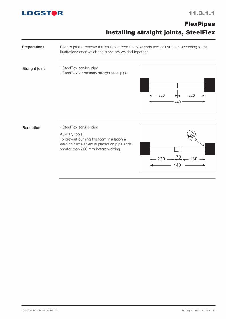
LOGSTOR A/S · Tel. +45 99 66 10 00 Handling and Installation · 2006.11
11.3.1.1
Straight joint
Reduction
FlexPipesInstalling straight joints, SteelFlex
Preparations
220 220
440
440220 15070
- SteelFlex service pipe- SteelFlex for ordinary straight steel pipe
- SteelFlex service pipe
Auxiliary tools:To prevent burning the foam insulation a welding flame shield is placed on pipe ends shorter than 220 mm before welding.
Prior to joining remove the insulation from the pipe ends and adjust them according to the illustrations after which the pipes are welded together.
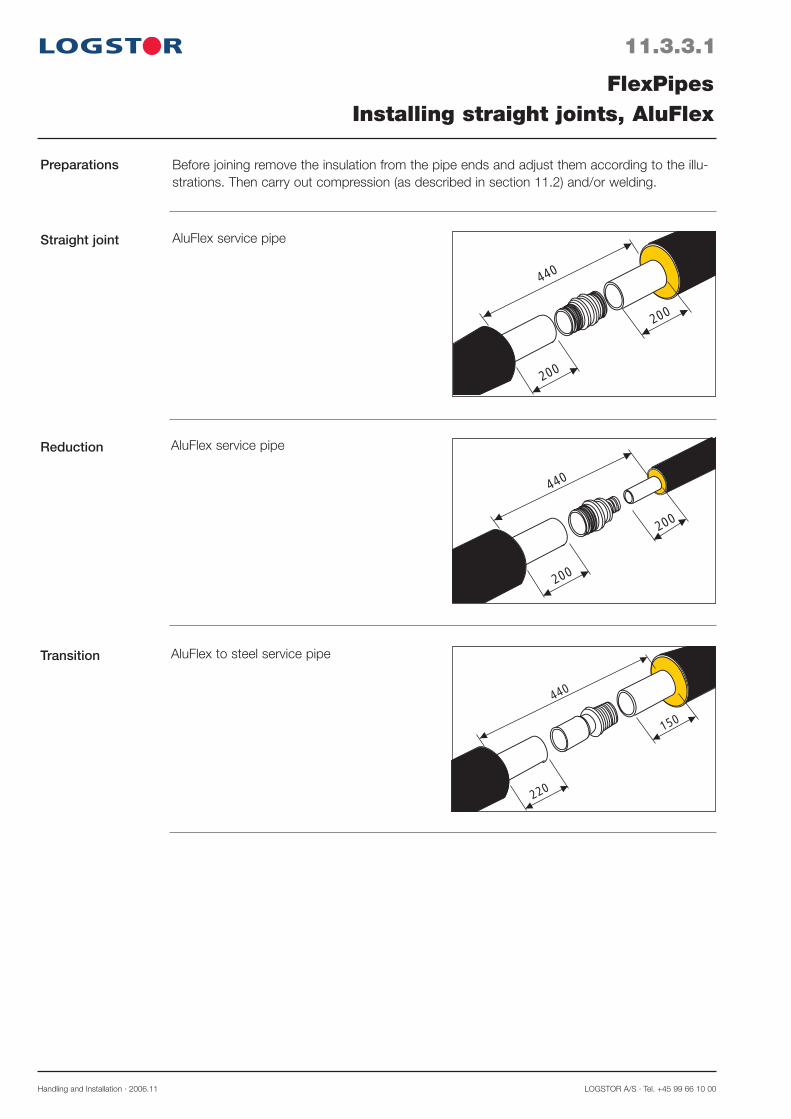
Straight joint
Reduction
Transition
200
440
200
200
440
200
220
440
150
AluFlex service pipe
AluFlex service pipe
AluFlex to steel service pipe
Handling and Installation · 2006.11 LOGSTOR A/S · Tel. +45 99 66 10 00
11.3.3.1
FlexPipesInstalling straight joints, AluFlex
Preparations Before joining remove the insulation from the pipe ends and adjust them according to the illu-strations. Then carry out compression (as described in section 11.2) and/or welding.
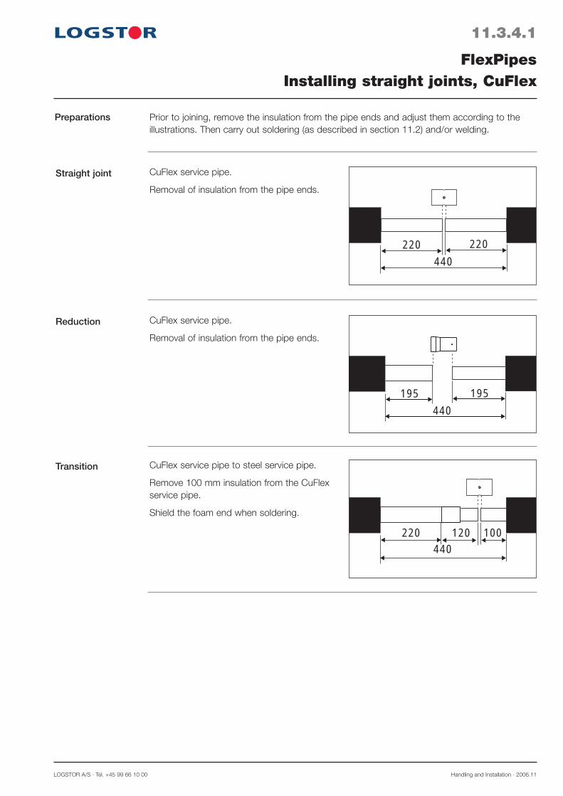
Transition
220 100440
120
CuFlex service pipe to steel service pipe.
Remove 100 mm insulation from the CuFlex service pipe.
Shield the foam end when soldering.
Reduction
195
440
195
CuFlex service pipe.
Removal of insulation from the pipe ends.
Straight joint
220 220
440
CuFlex service pipe.
Removal of insulation from the pipe ends.
LOGSTOR A/S · Tel. +45 99 66 10 00 Handling and Installation · 2006.11
11.3.4.1
FlexPipesInstalling straight joints, CuFlex
Preparations Prior to joining, remove the insulation from the pipe ends and adjust them according to the illustrations. Then carry out soldering (as described in section 11.2) and/or welding.
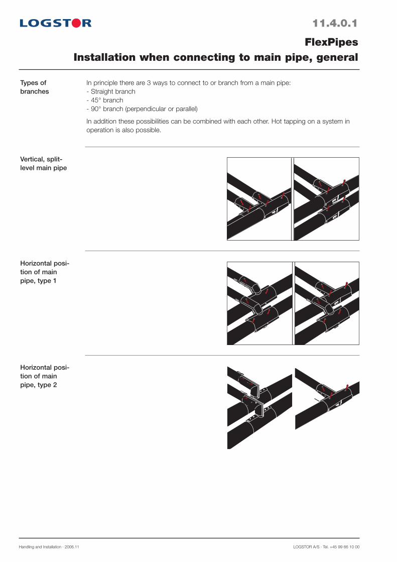
Handling and Installation · 2006.11 LOGSTOR A/S · Tel. +45 99 66 10 00
11.4.0.1
Types ofbranches
Vertical, split-level main pipe
Horizontal posi-tion of main pipe, type 1
Horizontal posi-tion of main pipe, type 2
FlexPipesInstallation when connecting to main pipe, general
In principle there are 3 ways to connect to or branch from a main pipe:- Straight branch- 45° branch- 90° branch (perpendicular or parallel)
In addition these possibilities can be combined with each other. Hot tapping on a system in operation is also possible.
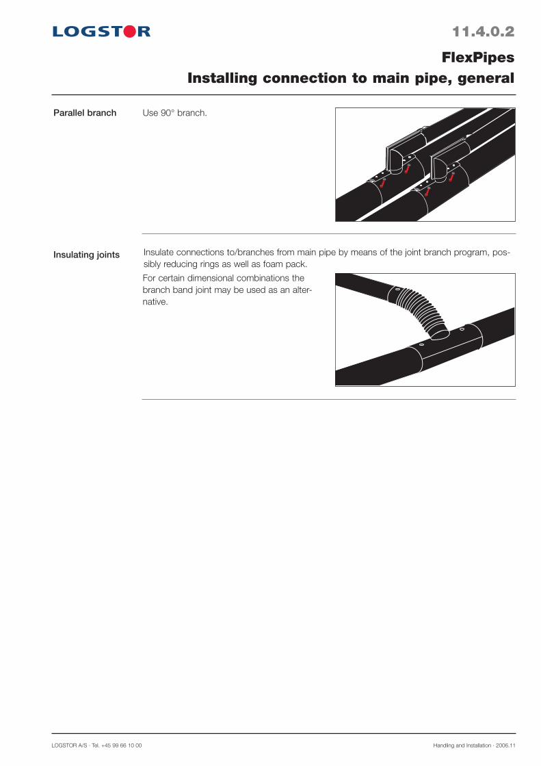
LOGSTOR A/S · Tel. +45 99 66 10 00 Handling and Installation · 2006.11
11.4.0.2
Parallel branch
Insulating joints
FlexPipesInstalling connection to main pipe, general
Insulate connections to/branches from main pipe by means of the joint branch program, pos-sibly reducing rings as well as foam pack.
For certain dimensional combinations the branch band joint may be used as an alter-native.
Use 90° branch.
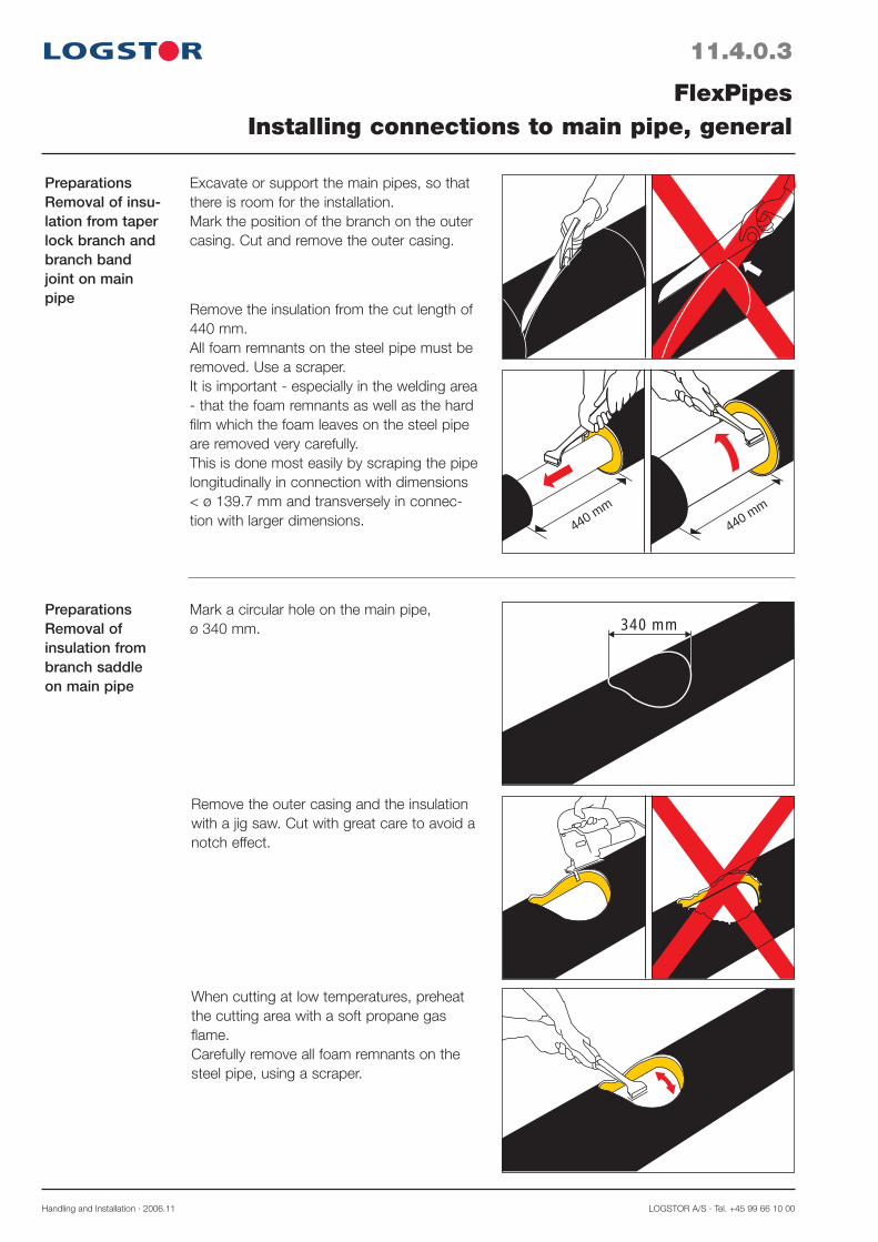
Handling and Installation · 2006.11 LOGSTOR A/S · Tel. +45 99 66 10 00
11.4.0.3
PreparationsRemoval of insu-lation from taper lock branch and branch band joint on main pipe
PreparationsRemoval of insulation from branch saddle on main pipe
FlexPipesInstalling connections to main pipe, general
440 mm440 mm
340 mm
Excavate or support the main pipes, so that there is room for the installation.Mark the position of the branch on the outer casing. Cut and remove the outer casing.
Mark a circular hole on the main pipe,ø 340 mm.
Remove the insulation from the cut length of 440 mm.All foam remnants on the steel pipe must be removed. Use a scraper.It is important - especially in the welding area - that the foam remnants as well as the hard film which the foam leaves on the steel pipe are removed very carefully.This is done most easily by scraping the pipe longitudinally in connection with dimensions < ø 139.7 mm and transversely in connec-tion with larger dimensions.
Remove the outer casing and the insulation with a jig saw. Cut with great care to avoid a notch effect.
When cutting at low temperatures, preheat the cutting area with a soft propane gas flame. Carefully remove all foam remnants on the steel pipe, using a scraper.
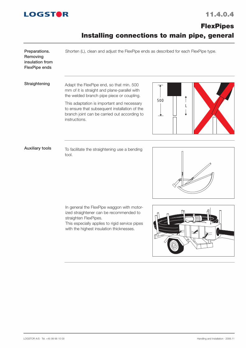
LOGSTOR A/S · Tel. +45 99 66 10 00 Handling and Installation · 2006.11
11.4.0.4
Preparations. Removing insulation from FlexPipe ends
Straightening
Auxiliary tools
FlexPipesInstalling connections to main pipe, general
Shorten (L), clean and adjust the FlexPipe ends as described for each FlexPipe type.
500L
Adapt the FlexPipe end, so that min. 500 mm of it is straight and plane-parallel with the welded branch pipe piece or coupling.
This adaptation is important and necessary to ensure that subsequent installation of the branch joint can be carried out according to instructions.
To facilitate the straightening use a bending tool.
In general the FlexPipe waggon with motor-ized straightener can be recommended to straighten FlexPipes.This especially applies to rigid service pipes with the highest insulation thicknesses.

Handling and Installation · 2006.11 LOGSTOR A/S · Tel. +45 99 66 10 00
11.4.1.1
Introduction
Hot tapping valve
Hot tapping tools
FlexPipesConnection to main pipe, hot tapping
A
B13 2
2
134
2
567
14
3
Branches with FlexPipes can be installed on systems in operation with hot tapping valves, made as ball valves in an all-welded steel casing in dimensions ø 26.9, ø 33.7 and ø 42.4 mm.
The small dimensions of the valves mean that they can be fitted into the 90° branches and branch saddles of the steel fittings system.
1. Hot tapping valve.2. Pipe end for direct welding of 90° branch
pipe piece.3. Conic pipe plug with hexagon socket4. Operating screw with slot, acting as posi-
tion indicator.
The complete hot tapping tool set is delivered in a case part no. 49915.1. Base tool with locksaw.2. Extra locksaws and centre drill3. Hexagon keys4. Screwdriver5. Knob for adapter6. O-rings and packing washers7. Hose
1. Base tool2. Locksaw complete3. Adapter
A. Flushing valveB. Stuffing box nut
Drilling machine (min. 800 W) is also used.
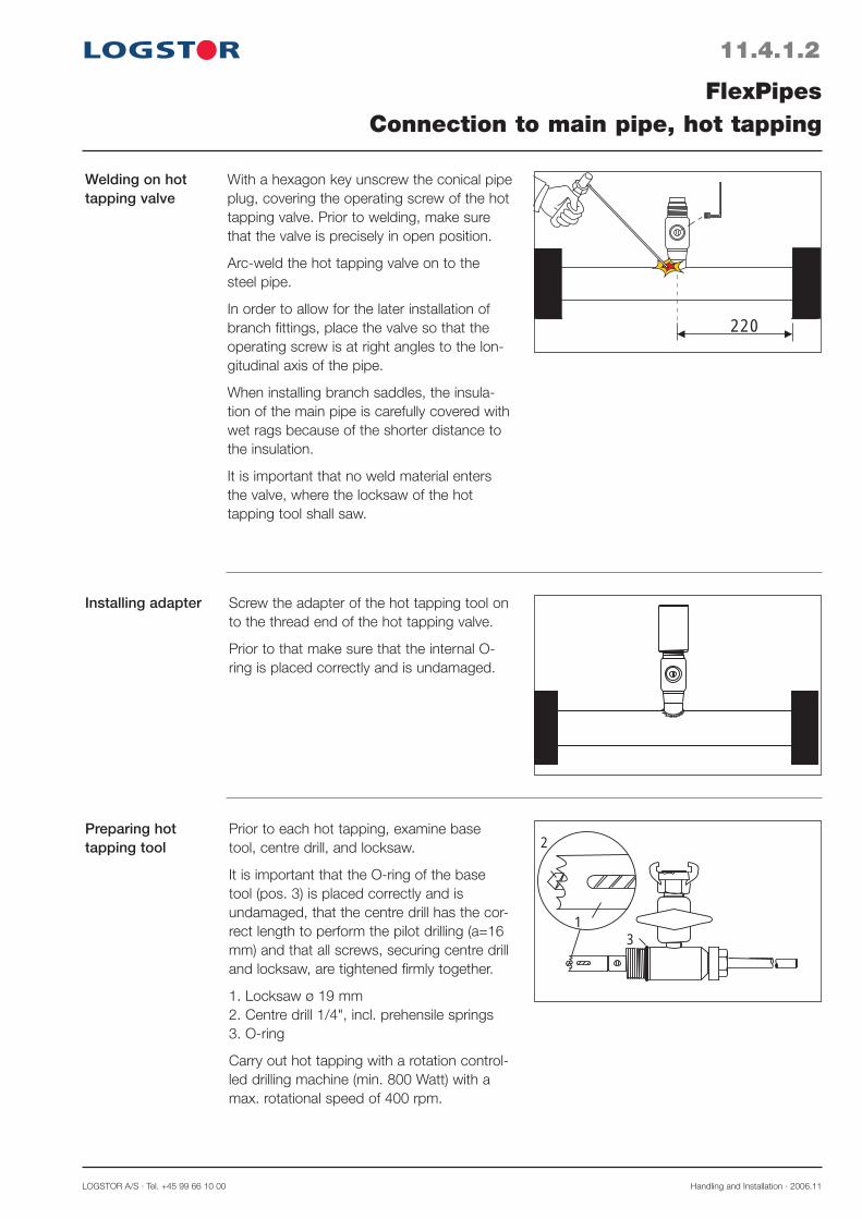
LOGSTOR A/S · Tel. +45 99 66 10 00 Handling and Installation · 2006.11
11.4.1.2
Welding on hot tapping valve
Installing adapter
Preparing hot tapping tool
FlexPipesConnection to main pipe, hot tapping
220
3
2
1
With a hexagon key unscrew the conical pipe plug, covering the operating screw of the hot tapping valve. Prior to welding, make sure that the valve is precisely in open position.
Arc-weld the hot tapping valve on to the steel pipe.
In order to allow for the later installation of branch fittings, place the valve so that the operating screw is at right angles to the lon-gitudinal axis of the pipe.
When installing branch saddles, the insula-tion of the main pipe is carefully covered with wet rags because of the shorter distance to the insulation.
It is important that no weld material enters the valve, where the locksaw of the hot tapping tool shall saw.
Screw the adapter of the hot tapping tool on to the thread end of the hot tapping valve.
Prior to that make sure that the internal O-ring is placed correctly and is undamaged.
Prior to each hot tapping, examine base tool, centre drill, and locksaw.
It is important that the O-ring of the base tool (pos. 3) is placed correctly and is undamaged, that the centre drill has the cor-rect length to perform the pilot drilling (a=16 mm) and that all screws, securing centre drill and locksaw, are tightened firmly together.
1. Locksaw ø 19 mm2. Centre drill 1/4", incl. prehensile springs3. O-ring
Carry out hot tapping with a rotation control-led drilling machine (min. 800 Watt) with a max. rotational speed of 400 rpm.
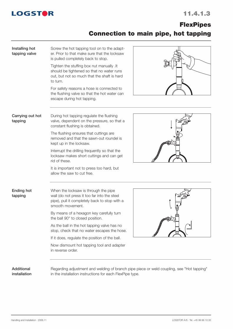
Handling and Installation · 2006.11 LOGSTOR A/S · Tel. +45 99 66 10 00
11.4.1.3
Installing hot tapping valve
Carrying out hot tapping
Ending hot tapping
FlexPipesConnection to main pipe, hot tapping
Screw the hot tapping tool on to the adapt-er. Prior to that make sure that the locksaw is pulled completely back to stop.
Tighten the stuffing box nut manually .It should be tightened so that no water runs out, but not so much that the shaft is hard to turn.
For safety reasons a hose is connected to the flushing valve so that the hot water can escape during hot tapping.
During hot tapping regulate the flushing valve, dependent on the pressure, so that a constant flushing is obtained.
The flushing ensures that cuttings are removed and that the sawn-out roundel is kept up in the locksaw.
Interrupt the drilling frequently so that the locksaw makes short cuttings and can get rid of these.
It is important not to press too hard, but allow the saw to cut free.
When the locksaw is through the pipe wall (do not press it too far into the steel pipe), pull it completely back to stop with a smooth movement.
By means of a hexagon key carefully turn the ball 90° to closed position.
As the ball in the hot tapping valve has no stop, check that no water escapes the hose.
If it does, regulate the position of the ball.
Now dismount hot tapping tool and adapter in reverse order.
Additional installation
Regarding adjustment and welding of branch pipe piece or weld coupling, see "Hot tapping" in the installation instructions for each FlexPipe type.

Handling and Installation · 2006.11 LOGSTOR A/S · Tel. +45 99 66 10 00
11.4.2.1
Introduction
FlexPipesConnection to main pipe, SteelFlex
This section primarily describes the adjustment measurements which are valid when connec-tion is made to main pipe with SteelFlex pipe.
- Straight connection to SteelFlex and ordinary preinsulated pipe- 45° connection to ordinary preinsulated pipe- 90° connection to ordinary preinsulated pipe- 90° hot tapping connection
Remove foam remnants on the SteelFlex service pipe with emery cloth, grain size 150.
Straight connection to SteelFlex pipe
290
440
190
180 11070
440
Direct welding.The dimension of the branch pipe must always be at least one dimension smaller than the dimension of the main pipe.
Prior to connection remove insulation and adjust pipe length in accordance with the illustra-tions.
Connecting SteelFlex service pipe with weld-T-piece and weld reductions.
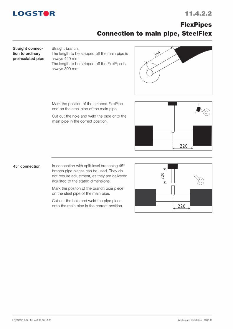
LOGSTOR A/S · Tel. +45 99 66 10 00 Handling and Installation · 2006.11
11.4.2.2
45° connection
FlexPipesConnection to main pipe, SteelFlex
Straight connec-tion to ordinary preinsulated pipe
300
220
220
220
Straight branch.The length to be stripped off the main pipe is always 440 mm.The length to be stripped off the FlexPipe is always 300 mm.
In connection with split-level branching 45° branch pipe pieces can be used. They do not require adjustment, as they are delivered adjusted to the stated dimensions.
Mark the positon of the branch pipe piece on the steel pipe of the main pipe.
Cut out the hole and weld the pipe piece onto the main pipe in the correct position.
Mark the position of the stripped FlexPipe end on the steel pipe of the main pipe.
Cut out the hole and weld the pipe onto the main pipe in the correct position.

Handling and Installation · 2006.11 LOGSTOR A/S · Tel. +45 99 66 10 00
11.4.2.3
90° connection
FlexPipesConnection to main pipe, SteelFlex
H
K
1 H1
220
220When split-level branching 90° branch pipe pieces may be used either perpendicular to or parallel with the main pipe.
Adjust the branch pipe piece to the actual insulation thickness.
Place the branch pipe piece on the steel pipe of the main pipe and measure the dis-tance between top of the outer casing and centre line of the pipe piece (H1).
The difference between (H1) and the H-measurement shown below (H2) is the length (K) by which the steel pipe end of the pipe piece must be shortened.
K = H1 - H2
H2 = 145 mm for taper lock branchesH2 = 125 mm for branch saddles
Mark the position of the pipe piece on the steel pipe of the main pipe. Cut out the hole and weld the pipe piece onto the main pipe in the correct position.
When installing branch saddles the insulation of the main pipe is carefully covered with wet rags due to the reduced distance to the insulation.

LOGSTOR A/S · Tel. +45 99 66 10 00 Handling and Installation · 2006.11
11.4.2.4
90° hot tapping connection
FlexPipesConnection to main pipe, SteelFlex
130
H2
K
A
H1
H3
Place the branch pipe piece on to the stripped steel pipe and measure the dis-tance between top of the outer casing and centre line of the branch pipe piece (H1).
The difference between H1 and the meas-urement shown below H2 is the length K.
Hold the branch pipe piece against the welded hot tapping valve and mark the length of the valve (A) as shown in the illus-tration.
Add and mark the length K.
The correct cutting length is thus H3 = A + K.
The measurement H2 is:- 165 mm for 90° branches on main pipes
with ø 90 mm outer casing.- 155 mm for 90° branches on all main
pipes with larger casing diameters.- 135 mm for branch saddles.
Weld the branch pipe piece on to the hot tapping valve in the correct position and adjust the SteelFlex branch pipe, cut it in the correct length and weld it on to the branch pipe piece.
Open the valve, screw the conic pipe plug in and weld it to obtain a completely welded system.

Handling and Installation · 2006.11 LOGSTOR A/S · Tel. +45 99 66 10 00
Introduction
11.4.4.1
Straight connection to AluFlex pipe
This section primarily describes the adjustment measurements which are valid when connect-ing to a main pipe with AluFlex pipes:
- straight connection to AluFlex and ordinary preinsulated pipe- 45° connection to ordinary preinsulated pipe- 90° connection to ordinary preinsulated pipe- 90° hot tapping connection
FlexPipesConnection to main pipe, AluFlex
The joint consists of the following:
1. AluFlex pipe2. Transition steel - AluPEX (weld coupling)3. Weld-T (full dimension)4. (Possibly) weld reduction
Prior to joining, remove the insulation and adjust the length according to the table and the illustration.
AluFlex Dimension L1 L2 L3 ø mm mm mm mm
22/77 136 136 141 28/90 136 86 151 32/77 126 76 77 32/90 126 76 137 40/90 116 66 127
1 1
1
2
2
3
44
L1
2
L2
L3
440
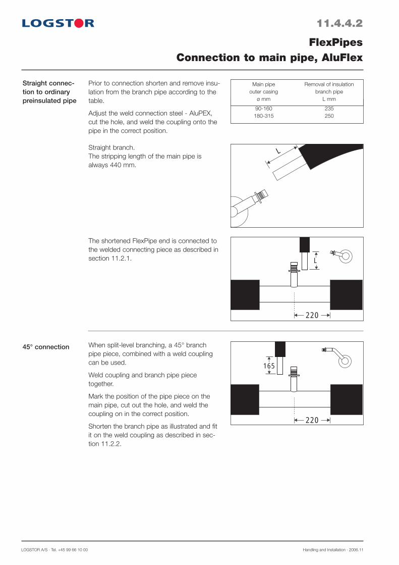
LOGSTOR A/S · Tel. +45 99 66 10 00 Handling and Installation · 2006.11
45° connection
Straight connec-tion to ordinary preinsulated pipe
11.4.4.2
FlexPipesConnection to main pipe, AluFlex
220
L
220
165
L
When split-level branching, a 45° branch pipe piece, combined with a weld coupling can be used.
Weld coupling and branch pipe piece together.
Mark the position of the pipe piece on the main pipe, cut out the hole, and weld the coupling on in the correct position.
Shorten the branch pipe as illustrated and fit it on the weld coupling as described in sec-tion 11.2.2.
Straight branch.The stripping length of the main pipe is always 440 mm.
The shortened FlexPipe end is connected to the welded connecting piece as described in section 11.2.1.
Prior to connection shorten and remove insu-lation from the branch pipe according to the table.
Adjust the weld connection steel - AluPEX, cut the hole, and weld the coupling onto the pipe in the correct position.
90-160 235 180-315 250
Main pipe Removal of insulation outer casing branch pipe ø mm L mm
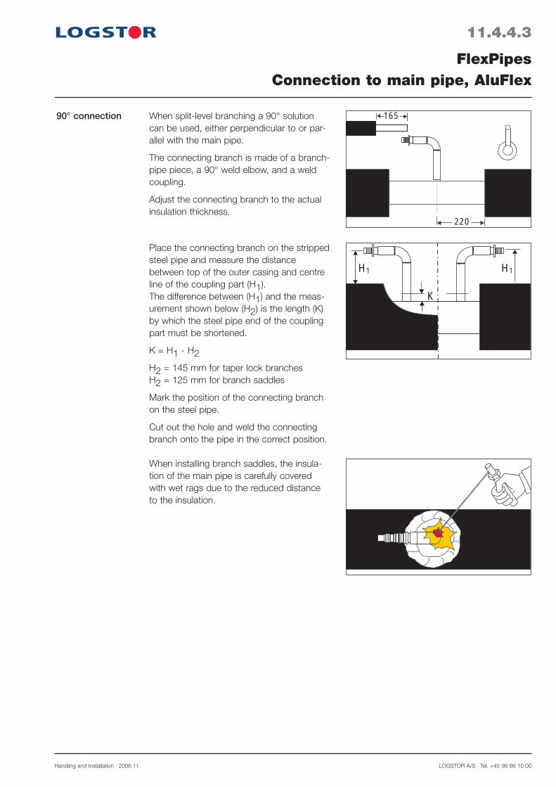
Handling and Installation · 2006.11 LOGSTOR A/S · Tel. +45 99 66 10 00
90° connection
11.4.4.3
FlexPipesConnection to main pipe, AluFlex
H
K
1 H1
220
165When split-level branching a 90° solution can be used, either perpendicular to or par-allel with the main pipe.
The connecting branch is made of a branch-pipe piece, a 90° weld elbow, and a weld coupling.
Adjust the connecting branch to the actual insulation thickness.
Place the connecting branch on the stripped steel pipe and measure the distance between top of the outer casing and centre line of the coupling part (H1).The difference between (H1) and the meas-urement shown below (H2) is the length (K) by which the steel pipe end of the coupling part must be shortened.
K = H1 - H2
H2 = 145 mm for taper lock branchesH2 = 125 mm for branch saddles
Mark the position of the connecting branch on the steel pipe.
Cut out the hole and weld the connecting branch onto the pipe in the correct position.
When installing branch saddles, the insula-tion of the main pipe is carefully covered with wet rags due to the reduced distance to the insulation.
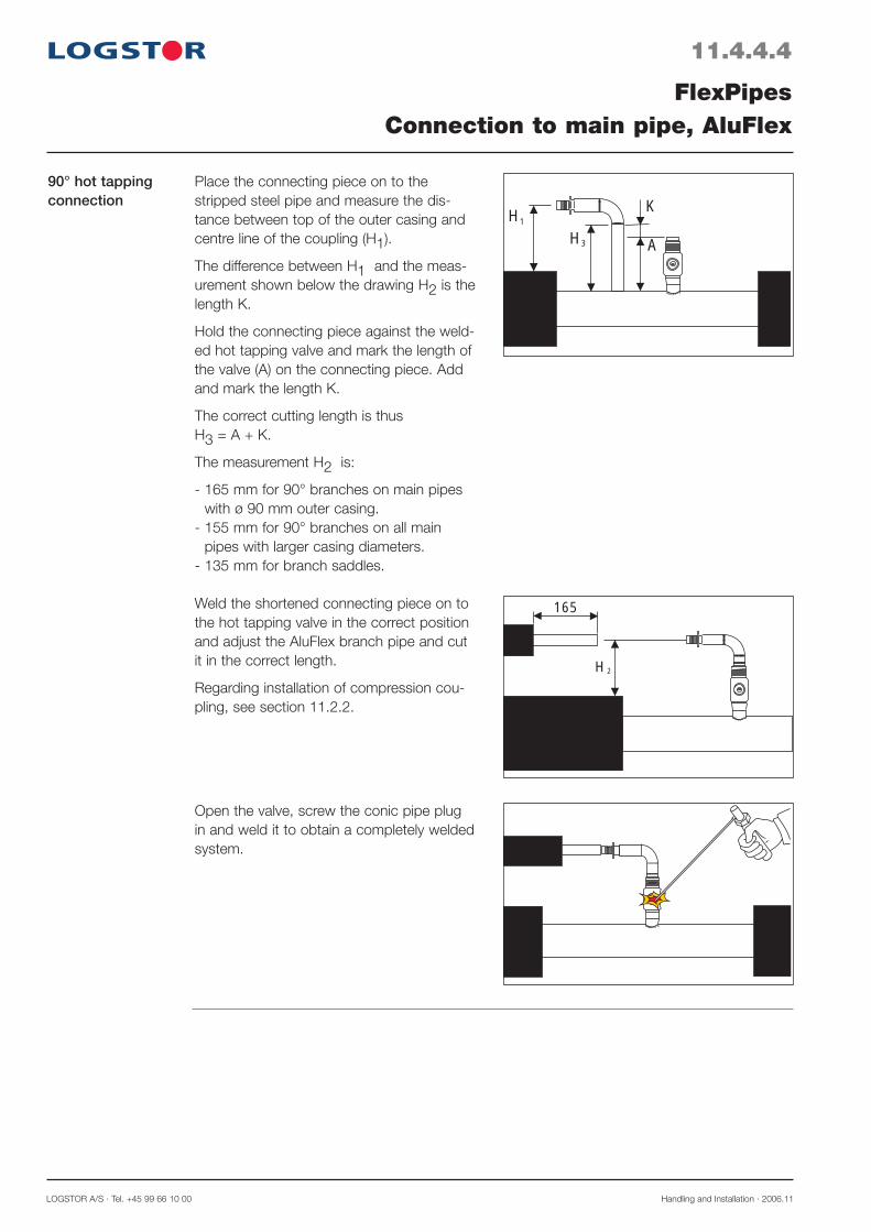
LOGSTOR A/S · Tel. +45 99 66 10 00 Handling and Installation · 2006.11
90° hot tapping connection
11.4.4.4
FlexPipesConnection to main pipe, AluFlex
2
165
H
HH A
K1
3
Place the connecting piece on to the stripped steel pipe and measure the dis-tance between top of the outer casing and centre line of the coupling (H1).
The difference between H1 and the meas-urement shown below the drawing H2 is the length K.
Hold the connecting piece against the weld-ed hot tapping valve and mark the length of the valve (A) on the connecting piece. Add and mark the length K.
The correct cutting length is thus H3 = A + K.
The measurement H2 is:
- 165 mm for 90° branches on main pipes with ø 90 mm outer casing.
- 155 mm for 90° branches on all main pipes with larger casing diameters.
- 135 mm for branch saddles.
Weld the shortened connecting piece on to the hot tapping valve in the correct position and adjust the AluFlex branch pipe and cut it in the correct length.
Regarding installation of compression cou-pling, see section 11.2.2.
Open the valve, screw the conic pipe plug in and weld it to obtain a completely welded system.

Handling and Installation · 2006.11 LOGSTOR A/S · Tel. +45 99 66 10 00
Introduction
11.4.5.1
Straight connection to CuFlex pipe with soldering T-pieces
FlexPipesConnection to main pipe, CuFlex
This section primarily describes the adjustment measurements which apply to connection to main pipe with CuFlex pipes:
- straight connection to CuFlex (with soldering-T-pieces or saddle pipe piece) and ordinary preinsulated pipe
- 45° connection to ordinary preinsulated pipe- 90° connection to ordinary preinsulated pipe- 90° hot tapping connection
285
205205
Connect the service pipes by means of sol-dering-T-pieces.
Prior to connection remove the insulation and adjust the length according to the illus-tration.
Straight connection to CuFlex pipe with saddle pipe piece
Mark the position of the saddle pipe piece on the main pipe.
Drill the hole and solder the saddle pipe piece on in the correct position.
Remove the insulation from the branch and adjust it, L = 235 mm.
220
235
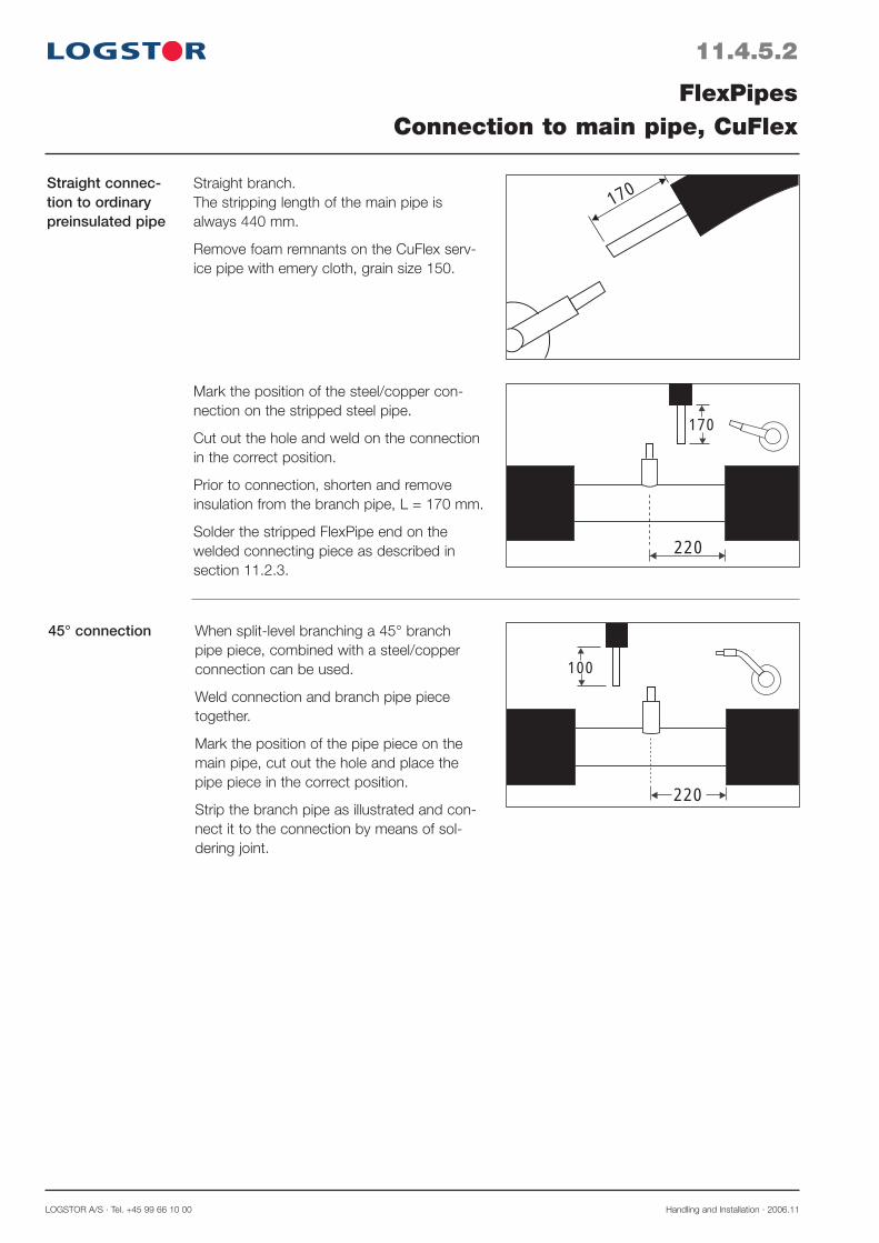
LOGSTOR A/S · Tel. +45 99 66 10 00 Handling and Installation · 2006.11
45° connection
11.4.5.2
FlexPipesConnection to main pipe, CuFlex
220
170
220
100
170
When split-level branching a 45° branch pipe piece, combined with a steel/copper connection can be used.
Weld connection and branch pipe piece together.
Mark the position of the pipe piece on the main pipe, cut out the hole and place the pipe piece in the correct position.
Strip the branch pipe as illustrated and con-nect it to the connection by means of sol-dering joint.
Straight branch.The stripping length of the main pipe is always 440 mm.
Remove foam remnants on the CuFlex serv-ice pipe with emery cloth, grain size 150.
Mark the position of the steel/copper con-nection on the stripped steel pipe.
Cut out the hole and weld on the connection in the correct position.
Prior to connection, shorten and remove insulation from the branch pipe, L = 170 mm.
Solder the stripped FlexPipe end on the welded connecting piece as described in section 11.2.3.
Straight connec-tion to ordinary preinsulated pipe

Handling and Installation · 2006.11 LOGSTOR A/S · Tel. +45 99 66 10 00
90° connection
11.4.5.3
FlexPipesConnection to main pipe, CuFlex
H
K
1 H1
220
100When split-level branching a 90° solution can be used, either perpendicular to or par-allel with the main pipe.
The connecting branch is made of a pipe piece, a 90° weld elbow, and a steel/copper connection.
Adjust the connecting branch to the actual insulation thickness.
Place the connecting branch on the stripped steel pipe and measure the distance between top of the outer casing and centre line of the copper part (H1).The difference between (H1) and the meas-urement shown below (H2) is the length (K) by which the steel pipe end of the coupling part must be shortened.
K = H1 - H2
H2 = 145 mm for taper lock branchesH2 = 125 mm for branch saddles
Mark the position of the connecting branch on the steel pipe.
Cut out the hole and weld the connecting branch onto the pipe in the correct position.
When installing branch saddles the insulation of the main pipe is carefully covered with wet rags due to the reduced distance to the insulation.
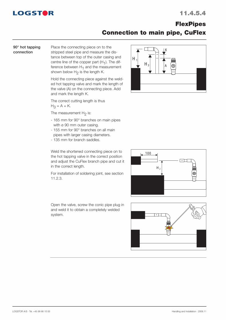
LOGSTOR A/S · Tel. +45 99 66 10 00 Handling and Installation · 2006.11
Open the valve, screw the conic pipe plug in and weld it to obtain a completely weldedsystem.
90° hot tapping connection
11.4.5.4
FlexPipesConnection to main pipe, CuFlex
Place the connecting piece on to the stripped steel pipe and measure the dis-tance between top of the outer casing and centre line of the copper part (H1). The dif-ference between H1 and the measurement shown below H2 is the length K.
Hold the connecting piece against the weld-ed hot tapping valve and mark the length of the valve (A) on the connecting piece. Add and mark the length K.
The correct cutting length is thus H3 = A + K.
The measurement H2 is:
- 165 mm for 90° branches on main pipes with ø 90 mm outer casing.
- 155 mm for 90° branches on all main pipes with larger casing diameters.
- 135 mm for branch saddles.
Weld the shortened connecting piece on to the hot tapping valve in the correct position and adjust the CuFlex branch pipe and cut it in the correct length.
For installation of soldering joint, see section 11.2.3.
HH
1
3
K
A
H2
100
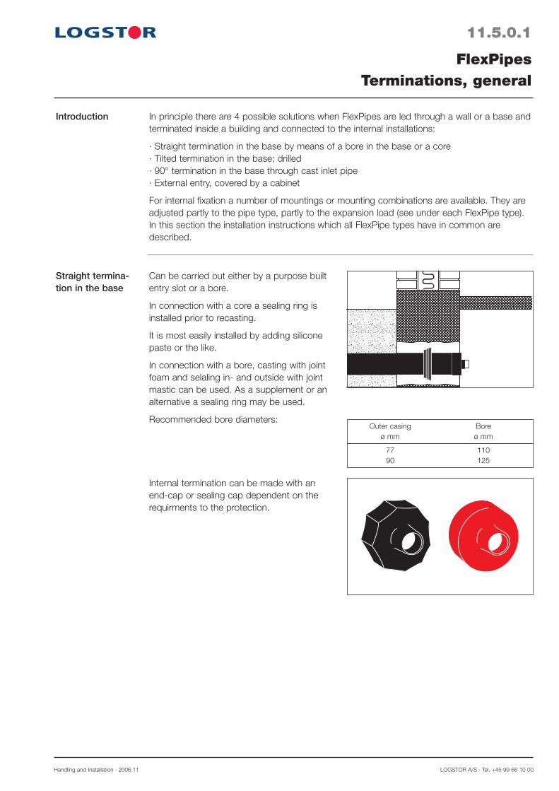
Handling and Installation · 2006.11 LOGSTOR A/S · Tel. +45 99 66 10 00
11.5.0.1
Introduction
FlexPipesTerminations, general
In principle there are 4 possible solutions when FlexPipes are led through a wall or a base and terminated inside a building and connected to the internal installations:
· Straight termination in the base by means of a bore in the base or a core· Tilted termination in the base; drilled· 90° termination in the base through cast inlet pipe· External entry, covered by a cabinet
For internal fixation a number of mountings or mounting combinations are available. They are adjusted partly to the pipe type, partly to the expansion load (see under each FlexPipe type).In this section the installation instructions which all FlexPipe types have in common are described.
Straight termina-tion in the base
yyyyyyyyyyyyyyyyyyyy
Internal termination can be made with an end-cap or sealing cap dependent on the requirments to the protection.
Can be carried out either by a purpose built entry slot or a bore.
In connection with a core a sealing ring is installed prior to recasting.
It is most easily installed by adding silicone paste or the like.
In connection with a bore, casting with joint foam and selaling in- and outside with joint mastic can be used. As a supplement or an alternative a sealing ring may be used.
Recommended bore diameters:
77 110 90 125
Outer casing Bore ø mm ø mm

LOGSTOR A/S · Tel. +45 99 66 10 00 Handling and Installation · 2006.11
11.5.0.2
FlexPipesTermination, general
Tilted bore in the base
yyyyyyyyyyyyyyyy
There must not be sharp edges on the outside.
Internal cover can be achieved with a seal-ing cap after previous sealing with joint foam and/or joint mastic.
Can be used in connection with introduction into existing buildings.
Recommended bore diameters:
77 110 90 125
Outer casing Bore diameter ø mm ø mm
Termination in the base through 90° cast inlet pipe
yyyyyyyyyyyy
A min min. 45 mm
100 mm
HR
L
ø
Installation measurements for inlet pipe:A = Min. 300 mm without traffic load
= Min. 400 mm with traffic load
Saw off surplus ends of the inlet pipe.
Centre the FlexPipe in the introduction opening.
Use a special pulling tool (see tools 24.7.1.1) to pull the pipe in through the wall.
Delivered measurements for inlet pipe:
77 7645 800 1050 900 125 90 7645 800 1050 900 125
Flex pipes Part R H L øø out. mm no. mm mm mm mm
2
1
Internal termination is made with (1) sealing reduction, ensuring centering between inlet pipe and outer casing of the FlexPipe, and covering with sealing cap (2).
Immediately prior to installation of the seal-ing, reduction sealing can be made with joint foam and/or joint mastic.
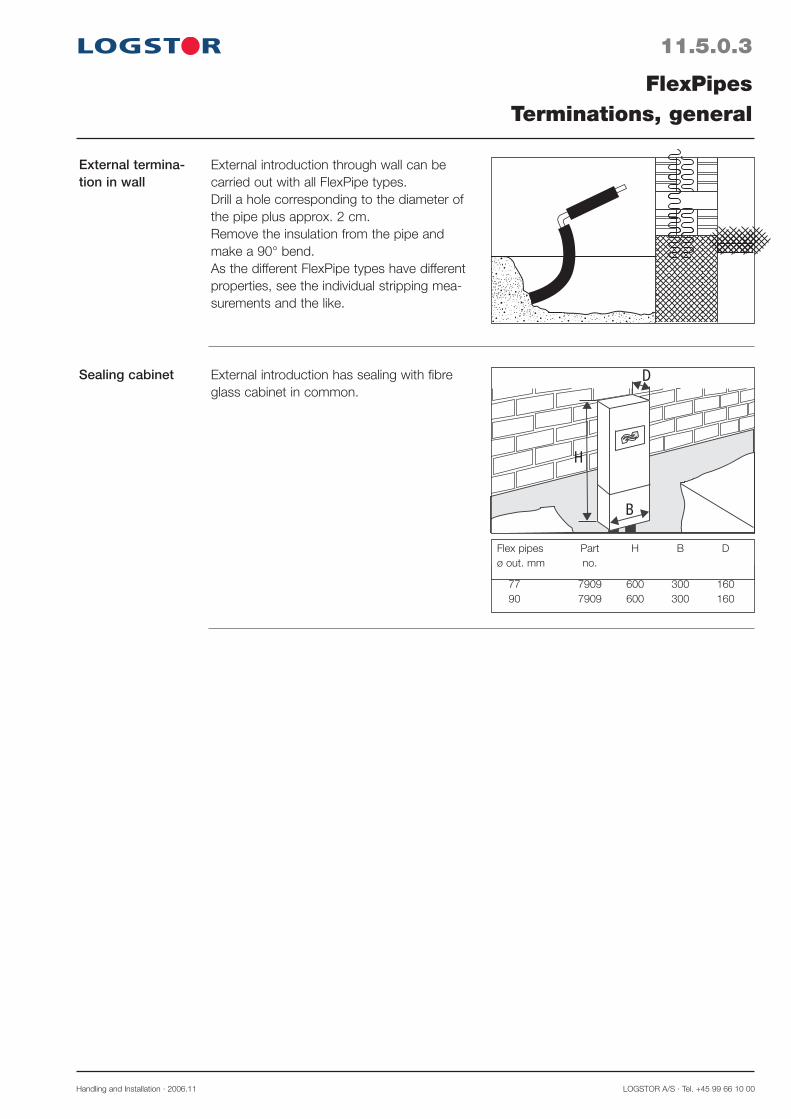
Handling and Installation · 2006.11 LOGSTOR A/S · Tel. +45 99 66 10 00
External termina-tion in wall
External introduction through wall can be carried out with all FlexPipe types.Drill a hole corresponding to the diameter of the pipe plus approx. 2 cm.Remove the insulation from the pipe and make a 90° bend.As the different FlexPipe types have different properties, see the individual stripping mea-surements and the like.
11.5.0.3
FlexPipesTerminations, general
Sealing cabinet
77 7909 600 300 160 90 7909 600 300 160
Flex pipes Part H B D ø out. mm no.
H
D
B
External introduction has sealing with fibre glass cabinet in common.


LOGSTOR A/S · Tel. +45 99 66 10 00 Handling and Installation · 2006.11
Catalogue pages
12.0.0.1
A temporary reference is made to the Løgstør Catalogue, section 6.4 LR-PEX for potable water.
PEX DW-pipe systemOverview


LOGSTOR A/S · Tel. +45 99 66 10 00 Handling and Installation · 2016.11
14.0.0.1
The TwinPipe systemOverview
Introduction
Contents
This section describes the special installation rules which apply when installing the TwinPipe system.
When the handling and installation instructions coincide with those for the single pipe system, reference is made to the latter.
General: Product Catalogue: TwinPipes 6.0 Design: TwinPipes 4.0 Handling and Installation: This manual
Trench 14.1 Straight pipes, fixing bars etc. 14.2 Bends and curves 14.3 Branches 14.4 Installing special casing joints for TwinPipes 14.5 - TX - T-joint - T-joint straight, doubleEnd fitting 14.6 Surveillance 14.7

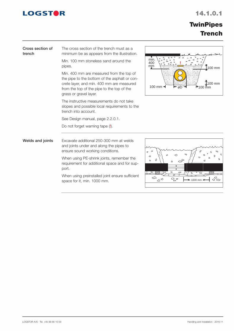
LOGSTOR A/S · Tel. +45 99 66 10 00 Handling and Installation · 2016.11
14.1.0.1
TwinPipesTrench
Cross section of trench
Welds and joints
100 mm 100 mm
100 mm
100 mm
mm400min.
!
øD
Excavate additional 250-300 mm at welds and joints under and along the pipes to ensure sound working conditions.
When using PE-shrink joints, remember the requirement for additional space and for sup-port.
When using preinstalled joint ensure sufficient space for it, min. 1000 mm. 1000 mm
The cross section of the trench must as a minimum be as appears from the illustration.
Min. 100 mm stoneless sand around the pipes.
Min. 400 mm are measured from the top of the pipe to the bottom of the asphalt or con-crete layer, and min. 400 mm are measured from the top of the pipe to the top of the grass or gravel layer.
The instructive measurements do not take slopes and possible local requirements to the trench into account.
See Design manual, page 2.2.0.1.
Do not forget warning tape (!).

Handling and Installation · 2016.11 LOGSTOR Fredericia A/S · Tel. +45 76 23 30 00
14.2.0.1
TwinPipesStraight pipes
General A welding method which in consideration of the distance between the steel pipes is suitable to weld TwinPipes is applied.
Position in trench
Termination of straight pipe runs
Usually place preinsulated TwinPipes and components, so one service pipe is directly over the other (flow pipe at the bottom).
The alarm wires must lie at the top of the joint.
Pipe label in 12 o’clock-position.
12
If a straight pipe run is not terminated with a preinsulated component with preinstalled fixing bars, then weld fixing bars on.
In connection with welding protect the foam against direct influence.
If the fixing bar is placed over a circumferen-tial weld, do not weld closer to this than 20 mm.
Weld fixing bars on both sides of the pipe end.
BH
Welding profile Correct weld, “a”-measurement.
HT
a

LOGSTOR A/S · Tel. +45 99 66 10 00 Handling and Installation · 2016.11
14.2.0.2
TwinPipesStraight pipes
Dimension and a-measure of fixing bars.
Fixing bars may also be manufactured on location. Use weldable steel quality.
amin = T2
Dimension of fix-ing bar
Dim. Measures, mm ø out mm B H T a min
26.9 50 46 4 3 33.7 50 53 4 3 42.4 50 61 4 3 48.3 50 67 4 3 60.3 70 80 4 3 76.1 90 96 4 3 88.9 110 114 6 4 114.3 140 139 6 4 139.7 170 170 6 4 168.3 200 208 6 4 219.1 260 264 8 6
Steel pipe dimensions ø 139.7 to 219.1 mm require additional removal of foam in order to make space for the fixing bars. c
Additional remov-al of foam
Steel pipe dimension ø mm
c mm
139.7 30
168.3 60
219.1 120
Bevellings Avoid bevellings in TwinPipe systems i.a. due to adaption of steel pipes. It is however re commended to use the elasticity of the pipes after straight welding instead and/or to use preinsulated bends or curved pipes.
Installation.Reduction
Use eccentric weld reductions.
Weld one set of fixing bars on the largest dimension.
Joint installation like installation of other joint reductions.
440 mm
220 ÷ LR
220L R
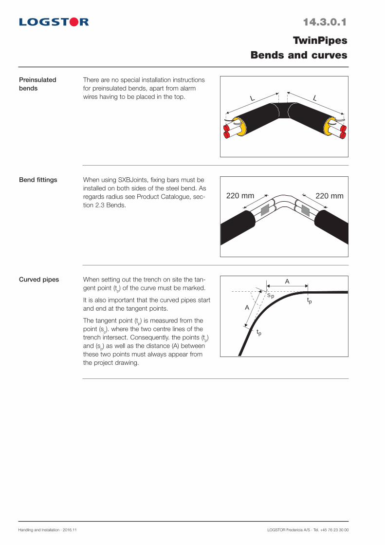
Handling and Installation · 2016.11 LOGSTOR Fredericia A/S · Tel. +45 76 23 30 00
14.3.0.1
TwinPipesBends and curves
Preinsulated bends
There are no special installation instructions for preinsulated bends, apart from alarm wires having to be placed in the top. LL
Bend fittings When using SXBJoints, fixing bars must be installed on both sides of the steel bend. As regards radius see Product Catalogue, sec-tion 2.3 Bends.
220 mm 220 mm
Curved pipes
Sp
p
A
A
t
pt
When setting out the trench on site the tan-gent point (tp) of the curve must be marked.
It is also important that the curved pipes start and end at the tangent points.
The tangent point (tp) is measured from the point (sp). where the two centre lines of the trench intersect. Consequently. the points (tp) and (sp) as well as the distance (A) between these two points must always appear from the project drawing.
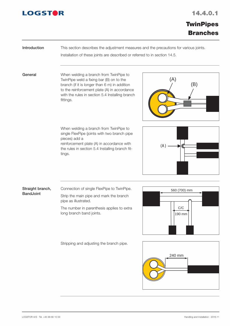
LOGSTOR A/S · Tel. +45 99 66 10 00 Handling and Installation · 2016.11
14.4.0.1
TwinPipesBranches
General
When welding a branch from TwinPipe to single FlexPipe (joints with two branch pipe pieces) add a reinforcement plate (A) in accordance with the rules in section 5.4 Installing branch fit-tings.
(A)
When welding a branch from TwinPipe to TwinPipe weld a fixing bar (B) on to the branch (if it is longer than 6 m) in addition to the reinforcement plate (A) in accordance with the rules in section 5.4 Installing branch fittings.
(A)(B)
This section describes the adjustment measures and the precautions for various joints.
Installation of these joints are described or referred to in section 14.5.
Introduction
Straight branch, BandJoint
Connection of single FlexPipe to TwinPipe.
Strip the main pipe and mark the branch pipe as illustrated.
The number in parenthesis applies to extra long branch band joints.
560 (700) mm
190 mm
C/C
Stripping and adjusting the branch pipe.
240 mm
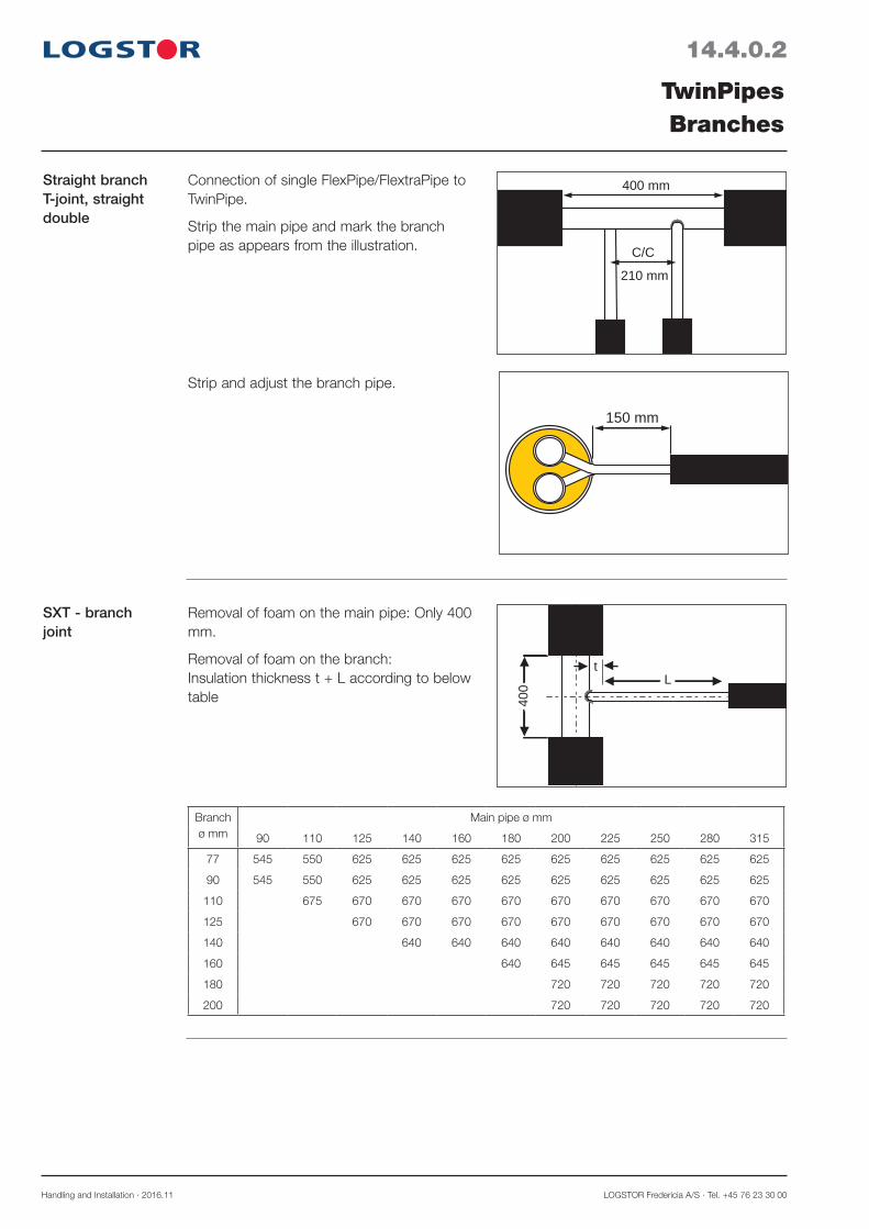
Handling and Installation · 2016.11 LOGSTOR Fredericia A/S · Tel. +45 76 23 30 00
14.4.0.2
TwinPipesBranches
SXT - branch joint
Removal of foam on the main pipe: Only 400 mm.
Removal of foam on the branch: Insulation thickness t + L according to below table 40
0
tL
Branch ø mm
Main pipe ø mm
90 110 125 140 160 180 200 225 250 280 315
77 545 550 625 625 625 625 625 625 625 625 625
90 545 550 625 625 625 625 625 625 625 625 625
110 675 670 670 670 670 670 670 670 670 670
125 670 670 670 670 670 670 670 670 670
140 640 640 640 640 640 640 640 640
160 640 645 645 645 645 645
180 720 720 720 720 720
200 720 720 720 720 720
Straight branch T-joint, straight double
Strip and adjust the branch pipe.
Connection of single FlexPipe/FlextraPipe to TwinPipe.
Strip the main pipe and mark the branch pipe as appears from the illustration.
400 mm
210 mm
C/C
150 mm

LOGSTOR A/S · Tel. +45 99 66 10 00 Handling and Installation · 2016.11
14.5.0.1
TwinPipesInstalling special joints for TwinPipes
Contents - TX - T-joint - T-joint straight, double
This section contains installation instructions for casing joints, exclusively made for the TwinPipe system.
References to casing joints which are common in connection with single pipe systems are listed below.
Introduction
References Joints Section
Straight joints:- SXJoint, ø 200-450 mm 5.2.4 - BXJoint, ø 125-630 mm 5.2.5 - B2SJoint, ø 500-630 mm 5.2.6- BSJoint, ø 125-560 5.2.7
Weld joints - BandJoint, ø 125-710 mm 5.2.1- PlateJoint, ø 780-1400 mm- EWJoint, ø 200-710 mm 5.2.2 - InduconJoint, ø 125-560 mm
Bend joints: - SXBJoint, ø 125-315 mm 5.3.1
Straight branches: - SXT branch joint, Main pipe: ø 90-315 mm 5.4.2
Branch: ø 90-200 mm
Weld branches:- BandJoint, Main pipe: ø 90-315 mm 5.4.3
Branch: ø 90-140 mm - TSJoint, Main pipe: ø 140-450 mm 5.4.4
Branch: ø 90-125 mm
Note! Additional accessories are required, when using BandJoints for TwinPipes, see Product Catalogue page 2.2.2.2.
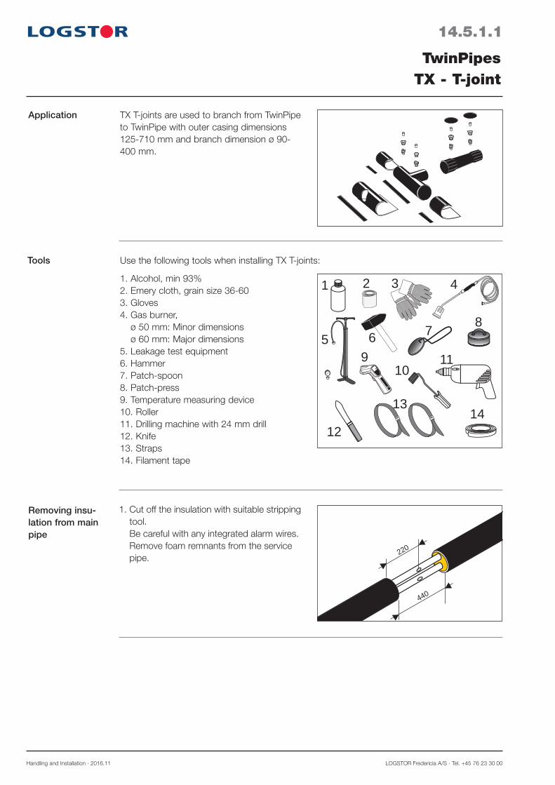
Handling and Installation · 2016.11 LOGSTOR Fredericia A/S · Tel. +45 76 23 30 00
14.5.1.1
TwinPipesTX - T-joint
Application TX T-joints are used to branch from TwinPipe to TwinPipe with outer casing dimensions 125-710 mm and branch dimension ø 90- 400 mm.
1. Cut off the insulation with suitable stripping tool. Be careful with any integrated alarm wires. Remove foam remnants from the service pipe.
220
440
Removing insu-lation from main pipe
Tools Use the following tools when installing TX T-joints:
1011
4
5 6
1 2 3
7 8
65°
9
12
1314
1. Alcohol, min 93%2. Emery cloth, grain size 36-603. Gloves4. Gas burner,
ø 50 mm: Minor dimensions ø 60 mm: Major dimensions
5. Leakage test equipment6. Hammer7. Patch-spoon8. Patch-press9. Temperature measuring device10. Roller11. Drilling machine with 24 mm drill12. Knife13. Straps14. Filament tape

LOGSTOR A/S · Tel. +45 99 66 10 00 Handling and Installation · 2016.11
14.5.1.2
TwinPipesTX - T-joint
Preinstalling shrink sleeve and T-shoe
4. All surfaces in the mounting area including T-shoe must be DRY and CLEAN. Now clean with alcohol.
150 mm
5. Grind the contact surfaces of T-shoe and wrap on the main pipe as well as the con-tact surfaces of the closure patch and wrap on the T-shoe with emery cloth, grain size 60.
2. Cut the T-shoe open in the middle of the bevelled area.
Preinstall shrink sleeve and T-shoe on the branch pipe.
3. Mount the branch on the main pipe.
Use transition pipe, component No. 0262, if required.
Connecting steel pipes
Cleaning
Activating main pipe and T-shoe
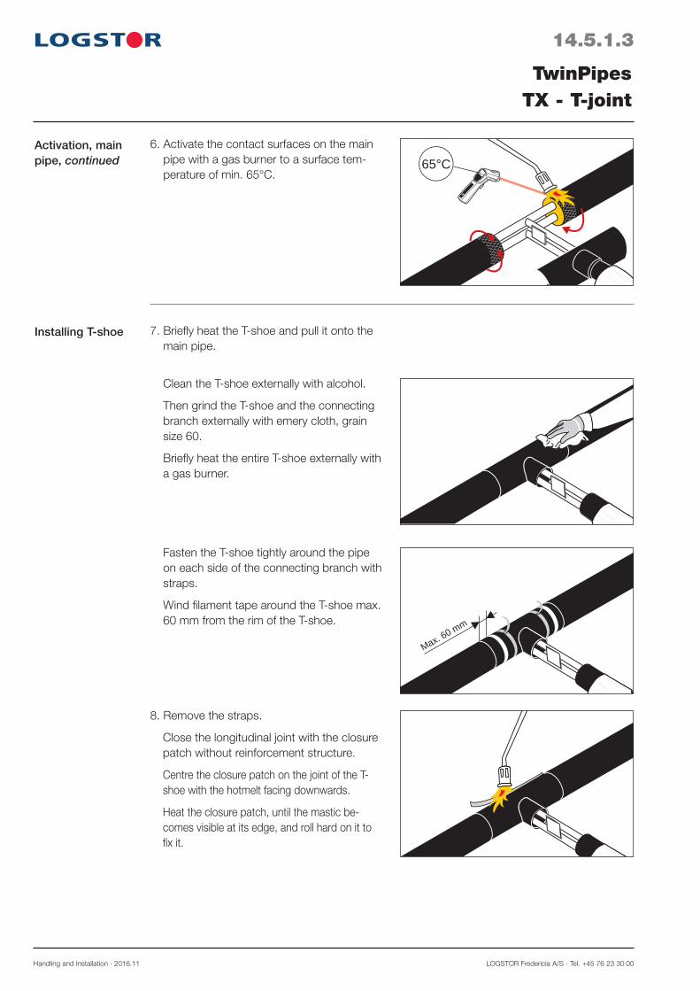
Handling and Installation · 2016.11 LOGSTOR Fredericia A/S · Tel. +45 76 23 30 00
14.5.1.3
TwinPipesTX - T-joint
Activation, main pipe, continued
65°
65°C6. Activate the contact surfaces on the main
pipe with a gas burner to a surface tem-perature of min. 65°C.
Installing T-shoe 7. Briefly heat the T-shoe and pull it onto the main pipe.
8. Remove the straps.
Close the longitudinal joint with the closure patch without reinforcement structure.
Centre the closure patch on the joint of the T-shoe with the hotmelt facing downwards.
Heat the closure patch, until the mastic be-comes visible at its edge, and roll hard on it to fix it.
Clean the T-shoe externally with alcohol.
Then grind the T-shoe and the connecting branch externally with emery cloth, grain size 60.
Briefly heat the entire T-shoe externally with a gas burner.
Fasten the T-shoe tightly around the pipe on each side of the connecting branch with straps.
Wind filament tape around the T-shoe max. 60 mm from the rim of the T-shoe.
Max. 60 mm

LOGSTOR A/S · Tel. +45 99 66 10 00 Handling and Installation · 2016.11
14.5.1.4
TwinPipesTX - T-joint
Shrinking collars
12. Grind the contact surfaces of the SX shrink sleeve on the outer casing and T-shoe.
Activating branch area
9. Activate the contact surfaces for the open collars on the T-shoe with a gas burner to a surface temperature of min. 65°C.. Centre a collar (bevelled corners) on one shrink sleeve end, so the fat end of the symbol faces the sleeve. Install the collar around the sleeve end with an overlap of 50 mm.
b
10. Centre the closure patch over the joint of the collar. Heat the closure patch, until the net struc-ture can be seen on the upper side. Press down the closure patch.
11. Shrink the collar with a gas burner, moving from the shrink sleeve towards the casing pipe. The sealing compound must be visible at both sides in the entire circumference. After shrinkage the surface structure must be smooth. Lightly roll along the the overlapping edge, ensuring that any tunnel is sealed with sealing compound.
Repeat steps 9, 10 and 11 with the other col-lar over the other sleeve end.

Handling and Installation · 2016.11 LOGSTOR Fredericia A/S · Tel. +45 76 23 30 00
14.5.1.5
TwinPipesTX - T-joint
15. Shrink until all expansion marks have faded and the end of the sleeve forms an almost straight encircling edge. A. before B. after
16. When the shrink sleeve has cooled off (max. lukewarm), leakage test the joint at 0.2 bar.
Test the joint ends visually with a soap solution.
A B
Leakage test
14. Remove the packing from the shrink sleeve. Do not use cutting tools with sharp edges. Make sure that the sleeve is CLEAN and DRY inside and out. Centre the sleeve on the joint and remove the mastic covering. Make sure that all the foil has been re-moved. Shrink the ends of the sleeve. Avoid heating directly on the casing. Shrink the sleeve starting at the top to ensure centering. At large dimensions support the joint at the middle to ease centering.
Installing shrink sleeve
65°
65°C
13. Activate the contact surfaces for the SX shrink sleeve with gas burner to a surface temperature of min. 65°C.
Activating branch area, continued

LOGSTOR A/S · Tel. +45 99 66 10 00 Handling and Installation · 2016.11
14.5.1.6
TwinPipesTX - T-joint
Expansion plugs 20. Remove the protective foil from the expansion plugs and check the sealing compound.
21. Activate the recessed area in the SXJoint and the two holes in the T-shoe briefly with a hard flame.
1
1-2 sec.
2
2
18. Install venting plugs in three of the holes. Two on the branch and one on the main pipe. Foam the sleeve through the fourth hole and install the fourth venting plug. Wait min. 30 min. for degassing. Remove the venting plugs by turning and lifting them. Remove excess foam or spill-age, if any. After cooling remove the straps.
Venting and foaming
19. Clean the entire surface of the recessed area around the holes in the SXJoint and the holes in the T-shoe with alcohol. Now grind the areas with emery cloth. Remove any grind dust.
Drilling foaming holes
17. Drill two foaming holes (ø 24 mm) in the T-shoe. Prior to foaming install 2 straps on the bottom of the T-shoe. One on each side of the branch.
Drilling foaming holes
1
2
30 min.

Handling and Installation · 2016.11 LOGSTOR Fredericia A/S · Tel. +45 76 23 30 00
14.5.1.7
TwinPipesTX - T-joint
Patch installation on branch
24. Place the patch on a patch-spoon, the adhesive side facing up. Heat the adhesive side, until the glue begins to bubble/boil.
20 sec.
25. Activate briefly, 1-2 sec., the recessed area with a hard flame. Place the patch over the plug in the recessed area, the adhesive side facing down. Heat the patch, until the green spots disappear.
26. Press it at once hard with the patch-press for min. 20 sec. The patch must fit tightly to the joint in the entire area and glue must be visible all around the patch. Repeat the process with the other patch over the other plug.
23. Centre the wedge plugs in the leading edge of the expansion plugs and drive them completely into the plugs with a hammer.
Wedge plugs
22. Mount the expansion plugs in the holes and press until the sealing compound is spread smoothly under the collar of the plug.
Expansion plugs,continued
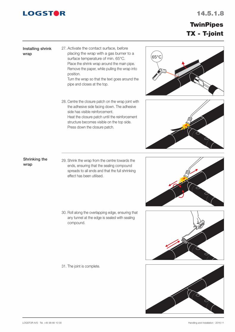
LOGSTOR A/S · Tel. +45 99 66 10 00 Handling and Installation · 2016.11
14.5.1.8
TwinPipesTX - T-joint
Shrinking the wrap
30. Roll along the overlapping edge, ensuring that any tunnel at the edge is sealed with sealing compound.
31. The joint is complete.
29. Shrink the wrap from the centre towards the ends, ensuring that the sealing compound spreads to all ends and that the full shrinking effect has been utilised.
28. Centre the closure patch on the wrap joint with the adhesive side facing down. The adhesive side has visible reinforcement.Heat the closure patch until the reinforcement structure becomes visible on the top side. Press down the closure patch.
27. Activate the contact surface, before placing the wrap with a gas burner to a surface temperature of min. 65°C.Place the shrink wrap around the main pipe. Remove the paper, while pulling the wrap into position.Turn the wrap so that the text goes around the pipe and closes at the top.
Installing shrink wrap
65°
65°C

Handling and Installation · 2016.11 LOGSTOR Fredericia A/S · Tel. +45 76 23 30 00
14.5.2.1
TwinPipesT-joint straight, double
Application T-joints straight, double are used to branch from TwinPipes to single pipes, primarily FlexPipes and FlextraPipes.
TwinPipe outer casing: ø 125-710 mm.
Branch pipe: ø 90-110 mm
400
210
2. Cut off 400 mm of the casing pipe and insulation. Beware of alarm wires. Clean the service pipe of excess insulation.
Removing insu-lation from main pipe
Tools Use the following tools when installing T-joint straight, double:
10
4
56
1 2 3
7 865°
9
Preparing T-shoe 1. Cut the T-shoe open in the middle of the bevelled area.
1. Alcohol, min 93%2. Emery cloth, grain size36-603. Gloves4. Gas burner,
ø 50 mm: Minor dimensions ø 60 mm: Major dimensions
5. Leakage test equipment6. Hammer7. Temperature measuring device8. Roller9. Drilling machine with ø 24 mm drill10. Knife
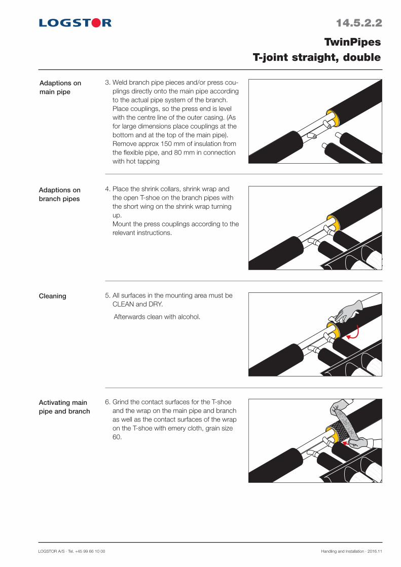
LOGSTOR A/S · Tel. +45 99 66 10 00 Handling and Installation · 2016.11
14.5.2.2
TwinPipesT-joint straight, double
Adaptions on main pipe
5. All surfaces in the mounting area must be CLEAN and DRY.
Afterwards clean with alcohol.
3. Weld branch pipe pieces and/or press cou-plings directly onto the main pipe according to the actual pipe system of the branch. Place couplings, so the press end is level with the centre line of the outer casing. (As for large dimensions place couplings at the bottom and at the top of the main pipe). Remove approx 150 mm of insulation from the flexible pipe, and 80 mm in connection with hot tapping
4. Place the shrink collars, shrink wrap and the open T-shoe on the branch pipes with the short wing on the shrink wrap turning up. Mount the press couplings according to the relevant instructions.
Adaptions on branch pipes
Cleaning
6. Grind the contact surfaces for the T-shoe and the wrap on the main pipe and branch as well as the contact surfaces of the wrap on the T-shoe with emery cloth, grain size 60.
Activating main pipe and branch
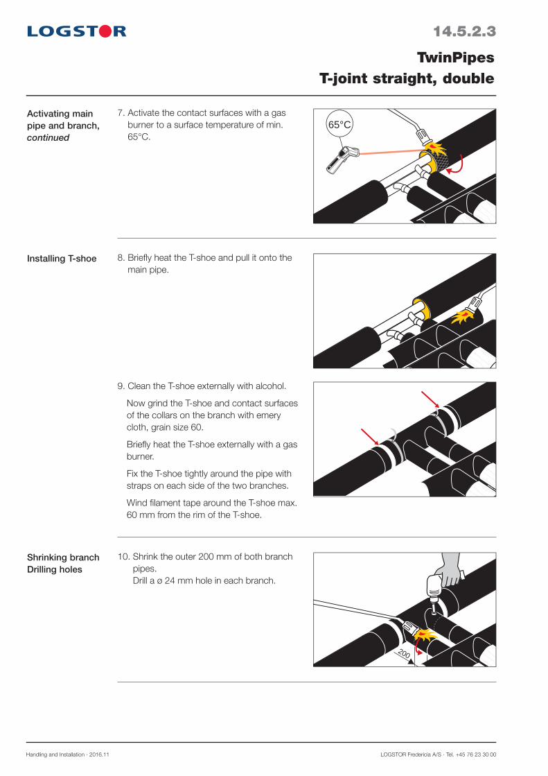
Handling and Installation · 2016.11 LOGSTOR Fredericia A/S · Tel. +45 76 23 30 00
14.5.2.3
TwinPipesT-joint straight, double
10. Shrink the outer 200 mm of both branch pipes.Drill a ø 24 mm hole in each branch.
Shrinking branchDrilling holes
7. Activate the contact surfaces with a gas burner to a surface temperature of min. 65°C.
65°
65°CActivating main pipe and branch, continued
8. Briefl y heat the T-shoe and pull it onto the main pipe.
Installing T-shoe
9. Clean the T-shoe externally with alcohol.
Now grind the T-shoe and contact surfaces of the collars on the branch with emery cloth, grain size 60.
Briefl y heat the T-shoe externally with a gas burner.
Fix the T-shoe tightly around the pipe with straps on each side of the two branches.
Wind fi lament tape around the T-shoe max. 60 mm from the rim of the T-shoe.
200

LOGSTOR A/S · Tel. +45 99 66 10 00 Handling and Installation · 2016.11
14.5.2.4
TwinPipesT-joint straight, double
14. Mount the expansion plugs in the holes and press, until the sealing compound is spread smoothly under the collar of the plug.
11. Install a venting plug in one of the holes and foam the sleeve through the other one. Install the other venting plug. Wait min. 30 min. for degassing. Remove the venting plugs by turning and lifting them. After cooling remove the straps.
Venting and foaming
Expansion plugs 12. Remove the protective foil from the expansion plugs and check the sealing compound.
13. Activate briefly the area around the holes with a hard flame.
1
1-2 sec.
2
Remove excess foam, if any. Activate the area around the holes with emery cloth, grain size 60. Now clean the T-shoe with alcohol.
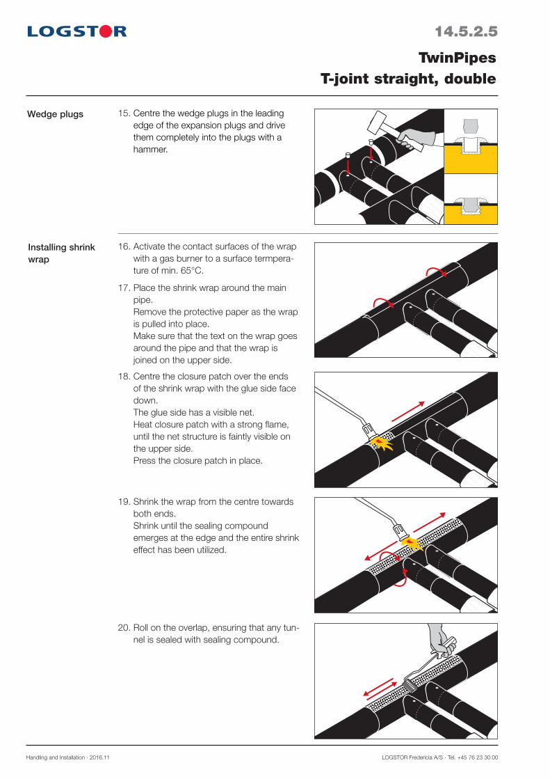
Handling and Installation · 2016.11 LOGSTOR Fredericia A/S · Tel. +45 76 23 30 00
14.5.2.5
TwinPipesT-joint straight, double
Installing shrink wrap
18. Centre the closure patch over the ends of the shrink wrap with the glue side face down. The glue side has a visible net. Heat closure patch with a strong flame, until the net structure is faintly visible on the upper side. Press the closure patch in place.
19. Shrink the wrap from the centre towards both ends. Shrink until the sealing compound emerges at the edge and the entire shrink effect has been utilized.
20. Roll on the overlap, ensuring that any tun-nel is sealed with sealing compound.
16. Activate the contact surfaces of the wrap with a gas burner to a surface termpera-ture of min. 65°C.
17. Place the shrink wrap around the main pipe. Remove the protective paper as the wrap is pulled into place. Make sure that the text on the wrap goes around the pipe and that the wrap is joined on the upper side.
15. Centre the wedge plugs in the leading edge of the expansion plugs and drive them completely into the plugs with a hammer.
Wedge plugs

LOGSTOR A/S · Tel. +45 99 66 10 00 Handling and Installation · 2016.11
14.5.2.6
TwinPipesT-joint straight, double
Activating the branch
23. The joint is complete.
22. Remove wrapping and paper from the collars. Check that all paper is removed. Shrink the first collar over the expansion plug. Then shrink the second collars onto the joint end.
21. Activate the contact surface for the collars with a gas burner to a surface tempera-ture of min. 65°C.
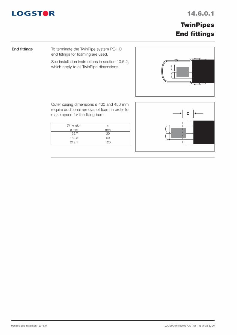
Handling and Installation · 2016.11 LOGSTOR Fredericia A/S · Tel. +45 76 23 30 00
14.6.0.1
TwinPipesEnd fittings
End fittings To terminate the TwinPipe system PE-HD end fittings for foaming are used.
See installation instructions in section 10.5.2, which apply to all TwinPipe dimensions.
Outer casing dimensions ø 400 and 450 mm require additional removal of foam in order to make space for the fixing bars. c
Dimension c ø mm mm 139.7 30 168.3 60 219.1 120
LOGSTOR A/S · Tel. +45 99 66 10 00 Handling and Installation · 2016.11
14.7.0.1
TwinPipesSurveillance
General
Installation
All preinsulated TwinPipes and preinsulated components to match are delivered with embed-ded copper wires for surveillance when connected to mobile or permanently installed measur-ing equipment.
This ensures a good inspection of the pipe system during the construction as well as the oper-ation phase for faults like:
- Faulty welds - Installation faults - Excavation damages
In principle connect alarm wires and components and check the system according to the installation instructions in section 23.0 of this manual.
Always have a circuit diagram ready before installation of the pipes and the installation.


LOGSTOR A/S · Tel. +45 99 66 10 00 Handling and Installation · 2010.04
15.0.0.1
The copper pipe systemOverview
Introduction
Contents
This section describes the special handling and installation rules for the copper pipe system with straight pipes.
When the handling and installation rules coincide with those of the bonded pipe system with steel service pipe, reference is made to the latter.
General: Product Catalogue: Copper pipes 7.0 Handling and Installation: This manual
For the flexible copper pipe system, CuFlex, see section 11.
Trench 15.1 Storage and handling 15.2 Soldering, general 15.3Casing joints, straight 15.4 Bends and curves 15.5 Branches 15.6 Surveillance 15.7


LOGSTOR A/S · Tel. +45 99 66 10 00 Handling and Installation · 2010.04
15.1.0.1
The copper pipe systemTrench
Basis
Cross section of trench
In order to ensure sufficient space for installation and for the protective and friction-generating sand layer the trench must be designed as described in this section.
As a minimum make the cross section of the trench as shown in the illustrations.
Min. 100 mm stoneless sand around the pipes.
In an unpaved area with no traffic the cover is minimum 400 mm from the top of the pipe to the top of the grass or gravel layer. In a paved area with heavy traffic it is minimum 400 mm from the top of the pipe to the bottom of the asphalt or concrete layer. (Also applies to branch pipes)
The instructive measurements do not take sloping systems and possible local requirements to the trench into account.
Do not forget warning tape (!)Single pipe
TwinPipe and double pipe
100 mm 100 mm
100 mm
100 mm
150
mm400min.
!
100 mm 100 mm
100 mm
100 mm
mm400min.
!
øD
Installationin trench
min. 400
L
The pipes can be installed in the trench, supported by cushions of sand or sleepers which are removed before the trench is filled with sand.
In case of joints it is recommended to increase the trench width and depth to 250-300 mm to ensure good space for soldering and installation of the joints.
Distance to the support in connection with preinstalled casing joints: L = Lcasing joint + 300 mm.

Handling and Installation · 2010.04 LOGSTOR Fredericia A/S · Tel. +45 76 23 30 00
15.2.0.1
The copper pipe systemStorage and handling
Storage
2750 mm500 mm
H m
ax. 1
.5 m
Handling
ø 90 - 125 mm
100mm
2500 mm
The pipes are therefore delivered with a protec-tive PE-cover
It is recommended to leave the cover on the pipes until they are to be soldered together.
Pipes with outside diameter from ø 90 to ø 125 mm are delivered in bundles of 3 pcs. in order to avoid transport and handling dam-ages.
Lift pipes with outer diameter ø 140 and ø 160 mm with a yoke or the like to avoid bending.
Use lifting straps of min. 100 mm width.
Handle soft copper wires carefully, so they do not deflect unintentionally or the pipe ends are deformed.
Store the pipes so they are not damaged.
Stack the pipes on a level surface of stone-less sand with cushions of sand as it appears from the illustration.
Instead of cushions of sand, sleepers with a min. width of 100 mm may be used.
Stack the pipes so their labels are at the same end. It facilitates the installation as regards connecting the surveillance wires.
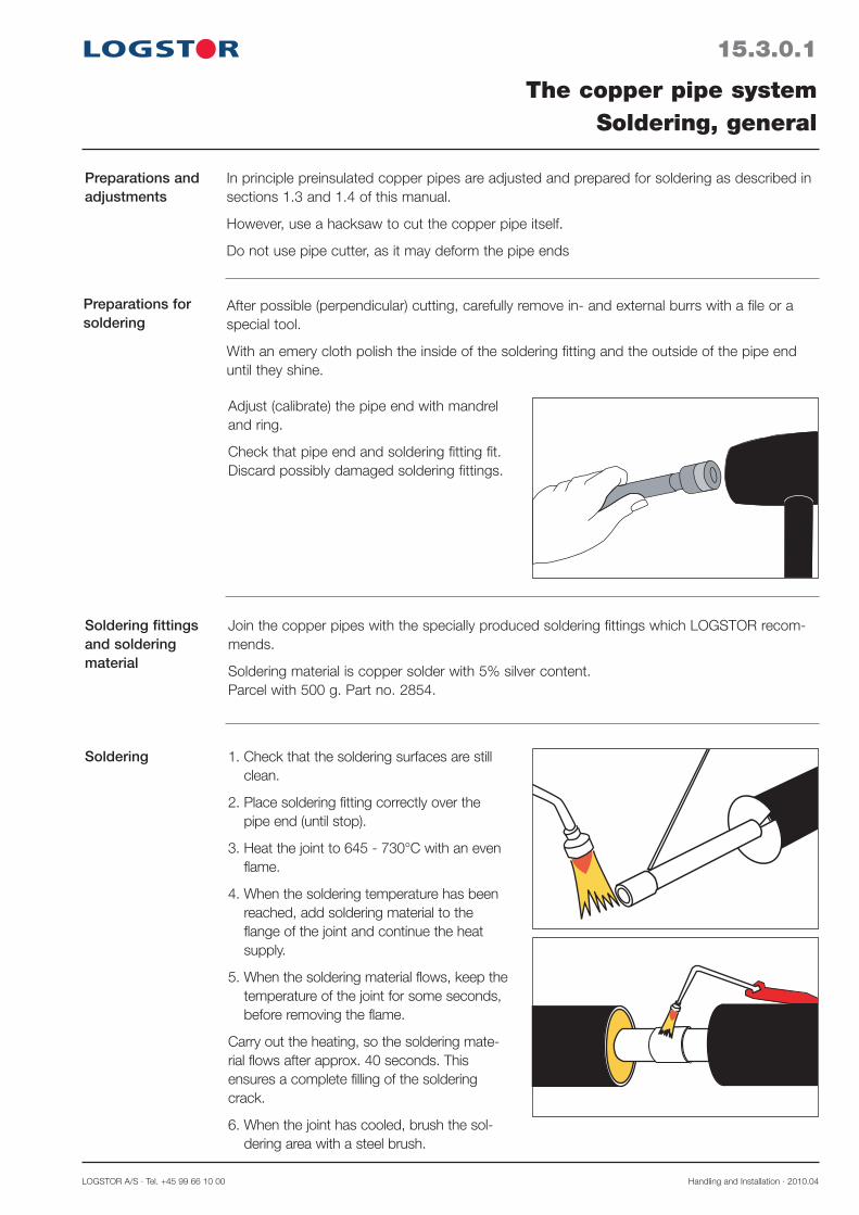
LOGSTOR A/S · Tel. +45 99 66 10 00 Handling and Installation · 2010.04
Soldering fittings and soldering material
Join the copper pipes with the specially produced soldering fittings which LOGSTOR recom-mends.
Soldering material is copper solder with 5% silver content. Parcel with 500 g. Part no. 2854.
Soldering 1. Check that the soldering surfaces are still clean.
2. Place soldering fitting correctly over the pipe end (until stop).
3. Heat the joint to 645 - 730°C with an even flame.
4. When the soldering temperature has been reached, add soldering material to the flange of the joint and continue the heat supply.
5. When the soldering material flows, keep the temperature of the joint for some seconds, before removing the flame.
Carry out the heating, so the soldering mate-rial flows after approx. 40 seconds. This ensures a complete filling of the soldering crack.
6. When the joint has cooled, brush the sol-dering area with a steel brush.
Preparations for soldering
After possible (perpendicular) cutting, carefully remove in- and external burrs with a file or a special tool.
With an emery cloth polish the inside of the soldering fitting and the outside of the pipe end until they shine.
Adjust (calibrate) the pipe end with mandrel and ring.
Check that pipe end and soldering fitting fit. Discard possibly damaged soldering fittings.
15.3.0.1
The copper pipe systemSoldering, general
Preparations and adjustments
In principle preinsulated copper pipes are adjusted and prepared for soldering as described in sections 1.3 and 1.4 of this manual.
However, use a hacksaw to cut the copper pipe itself.
Do not use pipe cutter, as it may deform the pipe ends
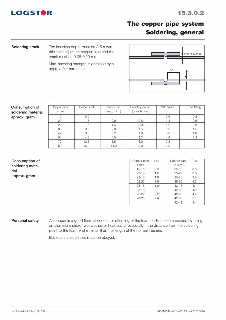
Handling and Installation · 2010.04 LOGSTOR Fredericia A/S · Tel. +45 76 23 30 00
As copper is a good thermal conductor shielding of the foam ends is recommended by using an aluminium shield, wet clothes or heat paste, especially if the distance from the soldering point to the foam end is minor than the length of the normal free end.
Besides, national rules must be obeyed.
Personal safety
15.3.0.2
The copper pipe systemSoldering, general
Soldering crack
0.05-0.20 mm
3-5 x s s
The insertion depth must be 3-5 x wall thickness (s) of the copper pipe and the crack must be 0.05-0.20 mm.
Max. shearing strength is obtained by a approx. 0.1 mm crack.
Consumption of soldering material approx. gram 15 0.6 0.6 0.3
22 1.3 0.9 0.6 1.3 0.6 28 1.6 1.4 0.8 1.6 0.8 35 3.0 2.3 1.5 3.0 1.5 42 3.6 3.2 1.8 3.6 1.8 54 4.6 4.0 2.3 4.6 2.3 70 12.5 8.5 6.0 12.5 89 16.0 14.0 8.0 16.0
Consumption of soldering mate-rial approx. gram
Copper pipe T-pc. Copper pipe T-pc. ø mm ø mm 15-15 0.9 35-18 3.5 22-15 1.6 35-22 3.6 22-18 1.8 35-28 3.8 22-22 1.9 35-35 4.5 28-15 1.9 42-18 4.1 28-18 2.1 42-22 4.2 28-22 2.2 42-28 4.4 28-28 2.4 42-35 5.1 42-42 5.4
Copper pipe Solder joint Reduction Saddle pipe pc. 90° bend End fitting ø mm (max. dim.) (branch dim.)

LOGSTOR A/S · Tel. +45 99 66 10 00 Handling and Installation · 2010.04
15.4.0.1
The copper pipe systemCasing joints, straight
Casing joint types
All our casing joint types for foaming can be used for straight joints, see section 2.2.
However, a supplementary set of accessories must be used for BandJoints: - BandJoint ø 125 - 200, see section 2.2.2
Foam packs: See section 7.11 in this manual which refers to the relevant foam pack numbers.

Handling and Installation · 2010.04 LOGSTOR Fredericia A/S · Tel. +45 76 23 30 00
General Directional changes in the copper pipe system are made with preinsulated 90° bends, 90° SteelJoint bends or by bending the pipes on site.
90° SteelJoint bends
Make a 90° bend with the normally 220 mm free pipe ends, combined with a 90° sol-dering joint.
Afterwards insulate the joint with a 90° SteelJoint bend and foam packs.
15.5.0.1
The copper pipe systemBends and curves
Shortening and removal of insula-tion
Single pipes and TwinPipe bends can be assembled without adjustments.
In connection with double pipes shorten the largest of the two pipes and the outer casing as shown in the illustration and in the table.
220 mm
L
ød1
ød2
A
øD
28-22 110 28 35-22 110 15 42-22 125 21 54-28 140 4 20 70-28 160 58 40
Dimension Shortening Stripping ød1-ød2 øD L mm A mm
Preinsulated bends
There are no special installation instructions for preinsulated bends, apart from alarm wires having to be placed in the top.
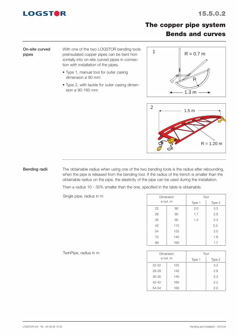
LOGSTOR A/S · Tel. +45 99 66 10 00 Handling and Installation · 2010.04
15.5.0.2
The copper pipe systemBends and curves
Bending radii The obtainable radius when using one of the two bending tools is the radius after rebounding, when the pipe is released from the bending tool. If the radius of the trench is smaller than the obtainable radius on the pipe, the elasticity of the pipe can be used during the installation.
Then a radius 10 - 30% smaller than the one, specified in the table is obtainable.
Single pipe, radius in m
TwinPipe, radius in m
On-site curved pipes
With one of the two LOGSTOR bending tools preinsulated copper pipes can be bent hori-zontally into on-site curved pipes in connec-tion with installation of the pipes.
Type 1, manual tool for outer casing •dimension ø 90 mm
Type 2, with tackle for outer casing dimen-•sion ø 90-160 mm 1.3 m
R
R = 0.7 m1
R = 1.20 m
1.5 m2
Dimension ø out. m
Tool
Type 1 Type 2
22 90 2.0 3.3
28 90 1.7 2.8
35 90 1.3 2.3
42 110 2.2.
54 125 2.0
70 140 1.8
89 160 1.7
Dimension ø out. m
Tool
Type 1 Type 2
22-22 125 3.3
28-28 140 2.8
35-35 140 2.3
42-42 160 2.2
54-54 160 2.0

Handling and Installation · 2010.04 LOGSTOR Fredericia A/S · Tel. +45 76 23 30 00
15.5.0.3
The copper pipe systemBends and curves
Vertical direction-al changes
Vertical directional changes with copper pipes in curves can only be made with single pipes.
Please contact LOGSTOR, as there are several changed conditions to consider.
Double pipe, radius in mBending radii,continued
Dimension ø out. m
Tool
Type 1 Type 2
22-15 90 2.0 3.3
28-22 110 2.8
35-22 110 2.3
42-22 125 2.2
54-28 140 2.0
70-28 160 1.8

LOGSTOR A/S · Tel. +45 99 66 10 00 Handling and Installation · 2010.04
A
220 mm
TwinPipe In connection with TwinPipes additional insulation must be removed according to the table.
Do not shorten the copper pipes.
Connection to saddle pipe piece:
15.6.0.1
The copper pipe systemBranches
General
Shortening and removal of insula-tion
Main pipe: All free copper pipe ends are 220 mm. All stripped lengths must be 440 mm.
Branch: Dependent on the branch type the service pipe or the insulation is shortened according to the specifications in the tables below.
220 mm
L
Single pipe In connection with single pipes, combined with saddle pipe piece shorten the branch as shown in the illustration and in the table.
Soldering-T does not require shortening.
Main pipe Shortening, L ø mm Branch, ø out. mm ø out. mm 22/90 28/90 35/90 42/110
22/90 30 28/90 30 30 35/90 40 40 42/110 30 30 30 0
Branching from the copper pipe system is made by:
a. Preinsulated branch-T orb. On-site installation and soldering of:
- Soldering-T: ø 22-42 mm or - Saddle pipe piece: ø 22-70 mm
All joints can be insulated with SteelJoint branches and foam packs.
Main pipe Removal of insulation, A mm Branch (S) ø out. m ø out. mm 22-22/125 28-28/140 35-35/140 42-42/160
22-22/125 45 28-28/140 45 45 35-35/140 45 45 42-42/160 45 45 45 0
Preinsulated branch-T
There are no special installation instructions for preinsulated branch-Ts.

Handling and Installation · 2010.04 LOGSTOR Fredericia A/S · Tel. +45 76 23 30 00
15.6.0.2
The copper pipe systemBranches
L2
220 mm
L1
A
Double pipe In connection with double pipes shortening and/or removal of insulation must be carried out according to the table.
22-15/90 22-15/90 7 20 28-22/110 22-15/90 35 38 6 20 28-22/110 28-22/110 35 38 6 20 35-22/110 22-15/90 35 40 15 20 35-22/110 28-22/110 35 40 15 20 35-22/110 35-22/110 35 40 15 20 42-22/125 22-15/90 10 22 35 90 42-22/125 28-22/110 10 30 35 90 42-22/125 35-22/110 10 22 35 90 42-22/125 42-22/125 22 90 54-28/140 22-15/90 48 40 54-28/140 28-22/110 48 40 54-28/140 35-22/110 48 40 54-28/140 42-22/125 48 40 54-28/140 54-28/140 48 40 70-28/160 22-15/90 56 50 70-28/160 28-22/110 56 50 70-28/160 35-22/110 56 50 70-28/160 42-22/125 56 50 70-28/160 54-28/140 56 50 70-28/160 70-28/160 56 50
Main pipe Branch Shortening mm Stripping outer casing ø out. mm ø out. mm Cu pipe A mm Saddle pipe pc. Soldering-T Saddle Solder- L1 L2 L1 L2 pipe pc. ing-T
Shortening/re-moval of insulation
Connection to soldering-T: Main pipe Removal of insulation, A mm Branch ø out. m ø out. mm 22-22/125 28-28/140 35-35/140 42-42/160
22-22/125 90 28-28/140 90 90 35-35/140 90 90 90 42-42/160 90 90 90 90
TwinPipe,continued
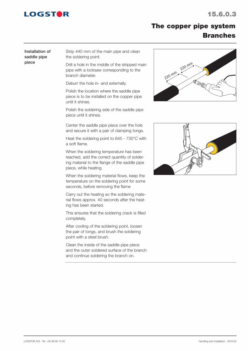
LOGSTOR A/S · Tel. +45 99 66 10 00 Handling and Installation · 2010.04
15.6.0.3
The copper pipe systemBranches
Installation of saddle pipe piece
220 mm220 mm
Strip 440 mm of the main pipe and clean the soldering point.
Drill a hole in the middle of the stripped main pipe with a locksaw corresponding to the branch diameter.
Deburr the hole in- and externally.
Polish the location where the saddle pipe piece is to be installed on the copper pipe until it shines.
Polish the soldering side of the saddle pipe piece until it shines.
Center the saddle pipe piece over the hole and secure it with a pair of clamping tongs.
Heat the soldering point to 645 - 730°C with a soft flame.
When the soldering temperature has been reached, add the correct quantity of solder-ing material to the flange of the saddle pipe piece, while heating.
When the soldering material flows, keep the temperature on the soldering point for some seconds, before removing the flame
Carry out the heating so the soldering mate-rial flows approx. 40 seconds after the heat-ing has been started.
This ensures that the soldering crack is filled completely.
After cooling of the soldering point, loosen the pair of tongs, and brush the soldering point with a steel brush.
Clean the inside of the saddle pipe piece and the outer soldered surface of the branch and continue soldering the branch on.

Handling and Installation · 2010.04 LOGSTOR Fredericia A/S · Tel. +45 76 23 30 00
15.7.0.1
The copper pipe systemSurveillance
General
Installation
All preinsulated copper pipes and components are available with embedded copper wires for surveillance for connection to portable or permanently installed measuring equipment.
This ensures a good check of the pipe system in the construction and operating phase of faults like:
- Solder faults - Installation faults - Excavation damages
Especially CuFlex alarm wires must be handled with care.
Connection of alarm wires, connection of components, and control of the pipeline in principle follow the installation instructions in section 23.0 of this manual.
Note! When the installation of coupling boxes or cables requires an earth connection, then the earth connection is special compared to the one for steel service pipes. The correct earth connection for copper pipes are: - Short model, 25 mm, product No. 8010 0000 018 092 (10 pcs.) - Long model; 100 mm, product No. 8010 0000 018 093 (10 pcs.)
Always have a circuit diagram before installing pipes.

LOGSTOR A/S · Tel. +45 99 66 10 00 Handling and Installation · 2006.11
17.0.0.1
The metal pipe casing systemOverview
Introduction This section will contain installation instructions for the metal pipe casing system.
Preinsulated pipes with metal casing are primarily used in connection with non-buried pipes above ground, in buildings or installation ducts.
Dimensional range: ø 33,7/100 mm to ø 1016/1250 mm.
Metal pipe casings are available as special products. Please contact us for further information.


LOGSTOR A/S · Tel. +45 99 66 10 00 Handling and Installation · 2006.11
18.0.0.1
Aquawarm copper pipe systemOverview
Introduction This section will contain installation instructions for the Aquawarm copper pipe system, mar-keted by LOGSTOR.
The insulation is made of mineral wool and the outer casing is corrugated PE.
Dimensional range:- single pipes; ø 12/93 mm to ø 88.9/186 mm- single pipes, extra insulation; ø 28/128 mm to ø 70/186 mm- double pipes; 2 x ø 15/128 mm to 2 x ø 42/186 mm
The Aquawarm copper pipe system is available as a special product. Please contact us for further information.


LOGSTOR A/S · Tel. +45 99 66 10 00 Handling & Installation · 2015.06
23.0.0.1
Introduction
Contents
LOGSTOR DetectOverview
Preinsulated pipe systems can be monitored for faults which are due to e.g. excavation, weld-ing, installation and the like. This ensures a good check of the pipe systems during installation as well as operation.
Principles of measuring, connection etc. 23.1Diagrams and symbols 23.2Checking alarm wires 23.3Connecting alarm wires 23.4Establishing earth connections 23.5Installing cables 23.6Installing connection and coupling boxes 23.7Surveillance components 23.8Weatherproof cabinets 23.9Surveillance of chambers 23.10

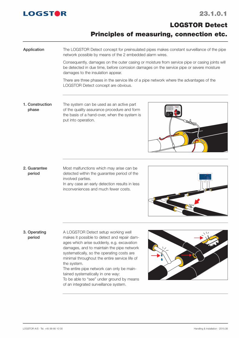
LOGSTOR A/S · Tel. +45 99 66 10 00 Handling & Installation · 2015.06
23.1.0.1
LOGSTOR DetectPrinciples of measuring, connection etc.
Application The LOGSTOR Detect concept for preinsulated pipes makes constant surveillance of the pipe network possible by means of the 2 embedded alarm wires.
Consequently, damages on the outer casing or moisture from service pipe or casing joints will be detected in due time, before corrosion damages on the service pipe or severe moisture damages to the insulation appear.
There are three phases in the service life of a pipe network where the advantages of the LOGSTOR Detect concept are obvious.
1. Construction phase >1000
TEST
V
OFF
SETUP
MeggerThe system can be used as an active part of the quality assurance procedure and form the basis of a hand-over, when the system is put into operation.
Most malfunctions which may arise can be detected within the guarantee period of the involved parties.In any case an early detection results in less inconveniences and much fewer costs.
2. Guarantee period
A LOGSTOR Detect setup working well makes it possible to detect and repair dam-ages which arise suddenly, e.g. excavation damages, and to maintain the pipe network systematically, so the operating costs are minimal throughout the entire service life of the system.The entire pipe network can only be main-tained systematically in one way:To be able to “see” under ground by means of an integrated surveillance system.
3. Operating period

Handling & Installation · 2015.06 LOGSTOR A/S · Tel. +45 99 66 10 00
23.1.0.2
LOGSTOR DetectPrinciples of measuring, connection etc.
System structure A surveillance system consists of: - Embedded copper wires in the delivered preinsulated pipes and components - Components for connection of equipment - Measuring equipment for permanent surveillance - Diagram of the total surveillance system. Requirement in EN 14419
Design and documentation of the wire run in a specific surveillance system are therefore an essential factor for the utilization of the surveillance system for fault location.
With a surveillance system a fault is measured by means of the wire length independent of the chosen system: - Passive system with manual detection
- Active systems with permanent detector surveillance 1. Resistance measuring 2. Impedance measuring

LOGSTOR A/S · Tel. +45 99 66 10 00 Handling & Installation · 2015.06
23.2.0.1
LOGSTOR DetectDiagrams and symbols
Introduction This section contains general and specific information on surveillance diagrams and their sym-bols.
Contents General 23.2.1
Diagrams and symbols, loop systems 23.2.2
Diagrams and symbols, single-wire (open) systems 23.2.3

Handling & Installation · 2015.06 LOGSTOR A/S · Tel. +45 99 66 10 00
23.2.1.1
LOGSTOR DetectDiagrams and symbols, general
Making diagrams It is vital that the surveillance diagram is finish before pipes are installed so the wire position can be correct. Requirement in EN 14419.
It is also vital that all changes of the pipe run are noted so a correct “as built”-diagram can be made.
Correspondence between diagram and pipe drawing is a condition of correct location of a possible malfunction.
LOGSTOR offers its assistance with the preparation of diagrams for surveillance systems.
Symbols LOGSTOR has prepared a set of symbols for design of surveillance systems which show where to use the specific components, but also the electric length of each connected cable for connection of detectors, check points or jumper cables in the system.
The tinned wire in the pipes is marked on the surveillance diagram with a full-drawn line. In open systems, using only single-wire detection the tinned wire is the alarm wire.
The copper wire in the pipes is marked in the surveillance diagram with a broken line. In loop systems it is part of the surveillance circuit.
It is also used when the signal is transmitted back and forth in the same pipe, e.g. in branch-es.

LOGSTOR A/S · Tel. +45 99 66 10 00 Handling & Installation · 2015.06
23.2.2.1
LOGSTOR DetectSymbol key, resistance measuring
Symbol key of the components
Components, primarily used in connection with: - resistance measuring - loop systems - Detector X1L components
Signature IllustrationName
Tinned copper wire
Copper wire
Earth connection for installation cables
Cable outlet at end cap with 2 m
Cable take-off from outer casing
Terminal box, 15171517
Detector X1L (X1L-G, X1L-BG) X1L
Weatherproof cabinet, narrow
1517
Connection cable, x m
5-conductor installation cable
Coupling box, 1518151151
Weatherproof cabinet, wide

Handling & Installation · 2015.06 LOGSTOR A/S · Tel. +45 99 66 10 00
23.2.2.2
LOGSTOR DetectSurveillance diagram, resistance measuring
Examples of surveillance dia-grams, made in accordance with the symbol key
The diagrams show various connection/combination possibilities related to the use of installa-tion cables, measuring boxes, and detectors in a system with resistance measuring.
Lw = max. wire length, incl. branches Ll = max. wire length in loop, incl. branches
Standard wiring Passive system
43
1 2
2
43
1
1517
1517
3
3
1
1
5
5
5
5
Lw = max. 500/1000 m Ll = max. 500/1000 m
Standard wiring Active system
43
1 2
1517
2
15
5
Lw = max. 400/800 m Ll = max. 400/800 m
2
1
1518
X1L
5
TwinPipeStandard wiring Active system
43
1 2
2
43
1
1517
1518
3
3
1
1
5
5
5
5
Lw = max. 500/1000 m Ll = max. 500/1000 m
1518
3
3
1
1 5
5
X1L
Lw/I = 500 m applies to the distribution pipeline Lw/I = 1000 m applies to the transmission pipeline
Lw/I = 500 m applies to the distribution pipeline Lw/I = 1000 m applies to the transmission pipeline
Lw/I = 400 m applies to the distribution pipeline Lw/I = 800 m applies to the transmission pipeline
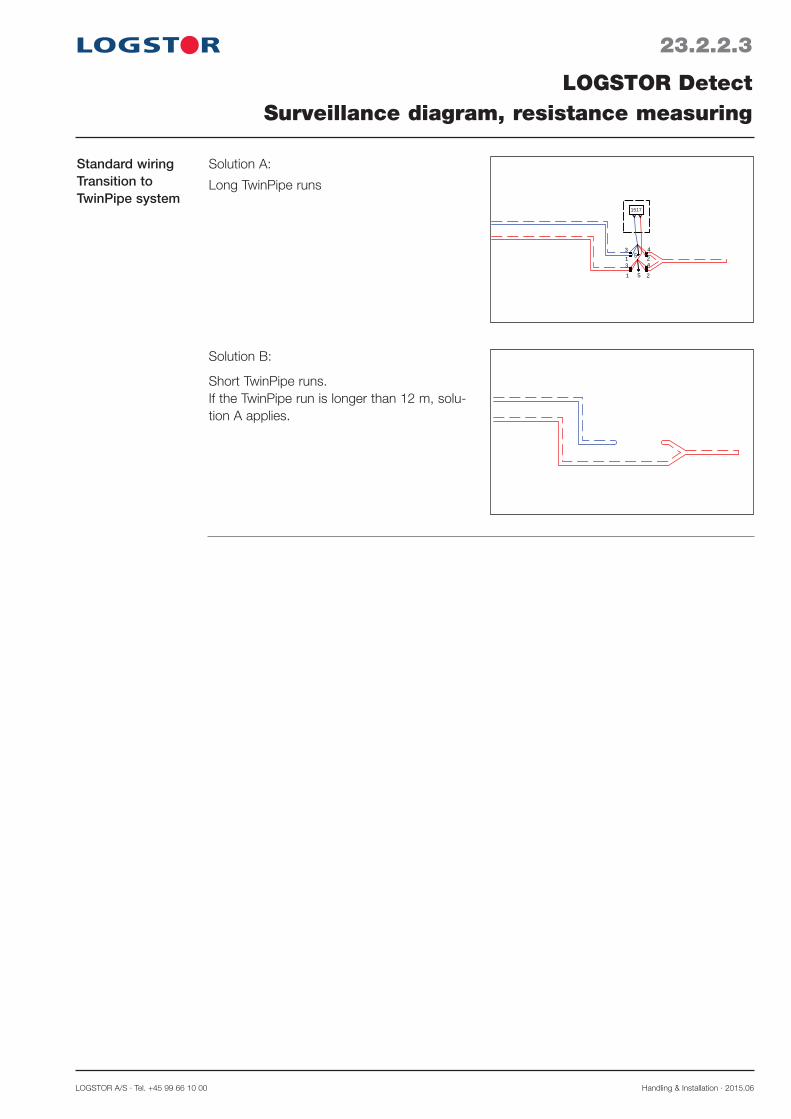
LOGSTOR A/S · Tel. +45 99 66 10 00 Handling & Installation · 2015.06
23.2.2.3
LOGSTOR DetectSurveillance diagram, resistance measuring
Standard wiringTransition to TwinPipe system
43
1 2
2
43
1
1517
5
5
Solution A:
Long TwinPipe runs
Solution B:
Short TwinPipe runs. If the TwinPipe run is longer than 12 m, solu-tion A applies.

Handling & Installation · 2015.06 LOGSTOR A/S · Tel. +45 99 66 10 00
23.2.3.1
LOGSTOR DetectSymbol key, impedance measuring
Symbol key of the components
Signature Illustration.
Name
Tinned copper wire
Copper wire
Earth connection for coaxial cables
Coaxial cable: (To be connected to MultiBox C2 and Detector X4)- 2.5 m- 5 m- 10 m
MultiBox C2C2
Detector X4X41234
Coaxial cable: (As a loop on MultiBox C2 in a building)- 0.5 m
Cable take-off at outer casing.For closed welding mirror.
Cable take-off at outer casing.For opening welding mirror.
Connecting link for 125 ohm coaxial cables
Weatherproof cabinet, narrow
Weatherproof cabinet, wide
Connecting link for BNC coaxial cables
Components, primarily used in connection with: - impedance measuring - coaxial cables - Detector X4

LOGSTOR A/S · Tel. +45 99 66 10 00 Handling & Installation · 2015.06
23.2.3.2
LOGSTOR DetectSurveillance diagram, impedance measuring
Examples of surveillance diagrams, made according to the symbol key
The diagrams show the various connection possibilities/combinations primarily related to the use of coaxial cables, measurement boxes and detectors in a system with impedance meas-uring.
Lw = recommended max. wire length, incl. branches Lo = recommended max. wire length, “open” wire, incl. branches
Standard wiring Two channels per pipe
43
12
Lw = max. 1000 m Lo = max. 1000 m
C2
C2 4.1
3.1
1.12.14
3
1
2
X41 42 3
*)
C2
C2
C2
C2
Standard wiring One channel per pipe
Lw = max. 1000 m Lo = max. 1000 m
C2
X41 423
1
2
1
2
1.1
2.1 *)
C2
C2
TwinPipe Standard wiringTwo channels per pipe, one direc-tion
Lw = max. 1000 m Lo = max. 500 m
C2
C2
C2
C2
4
3
1
2
X41 423
4
3
4.1
3.1
*) Loop is made, when the wire length of the loop does not exceed 5000 m.
*) Loop is made, when the wire length of the loop does not exceed 5000 m.

Handling & Installation · 2015.06 LOGSTOR A/S · Tel. +45 99 66 10 00
23.2.3.3
LOGSTOR DetectSurveillance diagram, impedance measuring
Example of tran-sition from single to TwinPipe sys-tem
Due to the measuring technique a take-off between the single pipe and the TwinPipe system must always be established.
1 2
Lw = max. 1000 m Lo = max. 500 m
C2 C
2
X41 423
2 3
41
3
4
3.1
4.1
TwinPipe Standard wiringTwo channels per pipe, two direc-tions
LOGSTOR A/S · Tel. +45 99 66 10 00 Handling & Installation · 2015.06
23.3.0.1
Introduction
Contents
Checking alarm wiresOverview
This section describes the installation and check of alarm wires in the surveillance system.
General 23.3.1The megger 23.3.2Using the megger. Checking alarm wires 23.3.3

Handling & Installation · 2015.06 LOGSTOR A/S · Tel. +45 99 66 10 00
23.3.1.1
Preparations
Straightening
Repairing wires
Checking alarm wiresGeneral
12
The two copper wires, embedded in the insulation, are delivered with protection against damage by winding and fixing them to the insulation by means of staples.When installing the pipes in the trench follow the specifications of the wire position in the surveillance diagram.
Place the pipes so the wires face upwards (10-to-2-o'clock position), and so the tinned wires and the copper wires are installed in pairs opposite each other.
This facilitates the installation and is a must in systems with pulse measuring and coaxial cables.
Wind the coiled wires from the countersink holes in the insulation, when the pipes have been welded together.
Remove dirt and moisture from the insulation of the pipe ends.
Straighten the wires and clean the ends with a cloth of synthetic textile or emery cloth.
Examine the wires for possible damage. If a wire has been damaged e.g. during removal of the insulation, remove the insulation around the wire end and solder a new piece of wire on as described in the following.
Note! Do not use a gas flame when solder-ing towards the insulation.
At each joint there must only be one pipe label and it must face upwards (12 o’clock position).
In the surveillance systems the alarm wires are placed at the top of the pipe in order to achieve i.a.: - optimum installation conditions - permanent accessibility of the wires when
establishing branches.
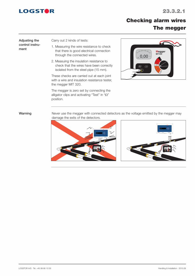
LOGSTOR A/S · Tel. +45 99 66 10 00 Handling & Installation · 2015.06
23.3.2.1
Adjusting the control instru-ment
Warning
Checking alarm wiresThe megger
0,00
TEST
V
OFF
SETUP
MeggerMIT320
Ω
Ω
kΩ
1kV
500 V
250 V
MΩ
Ω
0
1020 30
40
50
Never use the megger with connected detectors as the voltage emitted by the megger may damage the exits of the detectors.
FuseSupply
0,01
TEST
V
OFF
SETUP
MeggerMIT320
Ω
Ω
kΩ
1kV
500 V
250 V
MΩ
Ω
0
1020 30
40
50
0,01
TEST
V
OFF
SETUP
MeggerMIT320
Ω
Ω
kΩ
1kV
500 V
250 V
MΩ
Ω
0
1020 30
40
50
Carry out 2 kinds of tests:
1. Measuring the wire resistance to check that there is good electrical connection through the connected wires.
2. Measuing the insulation resistance to check that the wires have been correctly isolated from the steel pipe (15 mm).
These checks are carried out at each joint with a wire and insulation resistance tester, the megger MIT 320.
The megger is zero set by connecting the alligator clips and activating “Test” in “Ω” position.

Handling & Installation · 2015.06 LOGSTOR A/S · Tel. +45 99 66 10 00
Preparations for checking the joint
When beginning the wire installation, con-nect the wires in the two pipes as shown in the illustration. Tinned wire to copper wire in each pipe.
Hereby 2 measuring circuits are established which must be used to check the wire con-nections on the subsequent joints.
Naturally, in TwinPipes there are only 1 meas-uring circuit.
23.3.3.1
Checking alarm wiresUsing the megger
Test 1,wire resistance
1,20
TEST
V
OFF
SETUP
MeggerMIT320
Ω
Ω
kΩ
1kV
500 V
250 V
MΩ
Ω
0
1020 30
40
50
OFF
SETUP
Ω
Ω
kΩ
500 V
250 V
- Connect the instrument wires to the cleaned wire ends
- Place the switch in measuring range "Ω" The megger shows the actual ohmic resist-ance in the wires.
At the beginning of the installation the deflec-tion is insignificant, but it increases as more metres of wire are connected. Resistance measurement: Approx. 1.2 Ω at 100 m 1.5 mm2 wire.
If there is no deflection, there is no connec-tion.
If the resistance does not correspond to the actual length, a poor wire connection has been made in the previous joint.
- Check this joint and repair it. - Repeat the test.
Check both measuring circuits in the pipes in this way.
>100,0
TEST
V
OFF
SETUP
MeggerMIT320
Ω
Ω
kΩ
1kV
500 V
250 V
MΩ
Ω
0
1020 30
40
50
OFF
SETUP
Ω
Ω
kΩ
500 V
250 V

LOGSTOR A/S · Tel. +45 99 66 10 00 Handling & Installation · 2015.06
23.3.3.2
Test 2b,insulation resistance in MΩ
Checking alarm wiresUsing the megger
>1000
TEST
V
OFF
SETUP
MeggerMIT320
Ω
Ω
kΩ
1kV
500 V
250 V
MΩ
MΩ
0
1020 30
40
50
OFF
SETUP
Ω
Ω
kΩ
500 V
250 V
Note!Before carrying out this test make sure that NO dectectors are connected to the pipe system to avoid damage.
- Place the switch in measuring range: MΩ, 250 V.
- Connect one instrument wire to one of the wires in a pipe.
- Hold the other instrument wire against the steel pipe. Check that there is good electri-cal connection. Use the weld.
- Press the test knob, until the reading appears.
- The actual insulation resistance can now be read
Acceptance value: ≥ 10 MΩ/km wire
To measure a fault location exactly use a pulse reflectometer.
Test 2a,insulation resistance in kΩ
>1000
TEST
V
OFF
SETUP
MeggerMIT320
Ω
Ω
kΩ
1kV
500 V
250 V
MΩ
kΩ
0
1020 30
40
50
OFF
SETUP
Ω
Ω
kΩ
500 V
250 V
- Place the switch in measuring range: kΩ.
- Connect one instrument wire to one of the wires in the pipe.
- Hold the other instrument wire against the steel pipe. Check that there is good electri-cal connection. Use the weld.
Read off the insulation resistance.
If the reading is < 1000 kΩ, note the resist-ance for possible later reference.
If the reading is lower, an incorrect installation (moisture) has been made in the previous casing joint.
- Check the joint.- Remove possible moist foam.
Repeat the test.- Check all the wires in the joints in this way.- Now move the instrument to the next pipe
joint.
If the reading is > 1000 kΩ, continue to test 2b.

Handling & Installation · 2015.06 LOGSTOR A/S · Tel. +45 99 66 10 00
23.4.0.1
Introduction
Contents
Connecting alarm wiresOverview
This section contains instructions of wire installation for the various joints and components.
General 23.4.1Connecting alarm wires in joints for foaming 23.4.2 Connecting alarm wire in joints with insulation shells 23.4.3

LOGSTOR A/S · Tel. +45 99 66 10 00 Handling & Installation · 2015.06
23.4.1.1
Connecting wires
Soldering the wires
Connecting alarm wiresGeneral
1,5
1.5
6
1.5
6
Straighten the wires.
Cut the overlapping ends off.
Clean the wire ends with a synthetic textile or emery cloth.
Place a crimp connector on one of the wires and crimp it with the crimping tool, jaw width 1.5 mm.
The crimp connector has a stop in the mid-dle and a “window” for visual control that the insertion is correct.
Heat the crimp connector with the soldering iron. When its colour changes and becomes shiny the temperature is correct.Add tin solder with resin flux to both ends of the crimp connector. The soldering has been carried out correctly, when the tin has been absorbed in the ends of the crimp connector and becomes visible.Now a good electrical connection has also been established.
Insert the other wire into the crimp connec-tor and crimp it.
A good mechanical connection is now ensured.
Note! The wires must be tight, i.e. the same length as between the foam ends.
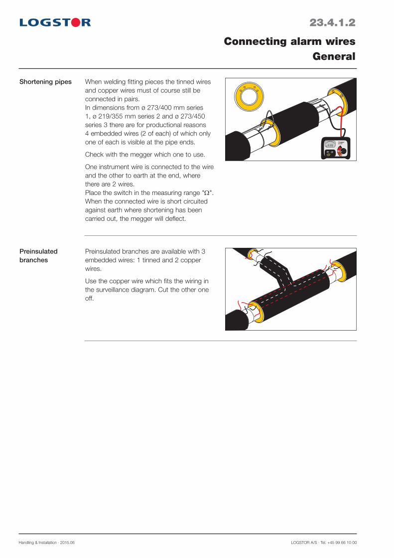
Handling & Installation · 2015.06 LOGSTOR A/S · Tel. +45 99 66 10 00
23.4.1.2
Preinsulated branches
Connecting alarm wiresGeneral
Preinsulated branches are available with 3 embedded wires: 1 tinned and 2 copper wires.
Use the copper wire which fits the wiring in the surveillance diagram. Cut the other one off.
Shortening pipes
0,01
TEST
V
OFF
SETUP
MeggerMIT320
Ω
Ω
kΩ
1kV
500 V
250 V
MΩ
Ω
0
1020 30
40
50
When welding fitting pieces the tinned wires and copper wires must of course still be connected in pairs.In dimensions from ø 273/400 mm series 1, ø 219/355 mm series 2 and ø 273/450 series 3 there are for produc tional reasons 4 embedded wires (2 of each) of which only one of each is visible at the pipe ends.
Check with the megger which one to use.
One instrument wire is connected to the wire and the other to earth at the end, where there are 2 wires.Place the switch in the measuring range "Ω". When the connected wire is short circuited against earth where shortening has been carried out, the megger will deflect.

LOGSTOR A/S · Tel. +45 99 66 10 00 Handling & Installation · 2015.06
23.4.1.3
Connecting alarm wiresGeneral
General wiring in connection with resistance and impedance measuring
A
B
In systems with resistance measuring the alarm wires are connected in a loop (A).In systems with impedance measuring the wires may be connected in a loop (A) or open (B) dependent on the actual wire length.In practice this means that the wire closest to the branch is connected to the branch. So there can be branches on the wire from the detector as well as the wire returning to the detector.
In systems with impedance measuring and alarm wires up to max. 5000 m the wires can be connected so in principle the tinned wire is always the only one to measure (“open” system). So all branches are connected to the same wire. The copper wire is primarily used as an aux-iliary wire and always in branches with loops. See diagram page 23.2.3.2 “Standard wiring. One channel per pipe”.
Special wiring in connection with impedance measuringL = max. 5000 m
( )
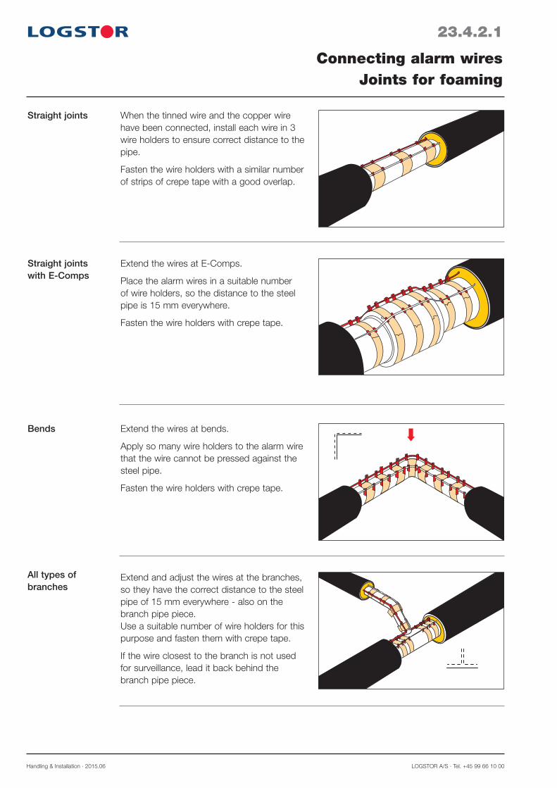
Handling & Installation · 2015.06 LOGSTOR A/S · Tel. +45 99 66 10 00
23.4.2.1
Connecting alarm wiresJoints for foaming
Straight joints When the tinned wire and the copper wire have been connected, install each wire in 3 wire holders to ensure correct distance to the pipe.
Fasten the wire holders with a similar number of strips of crepe tape with a good overlap.
Straight joints with E-Comps
Extend the wires at E-Comps.
Place the alarm wires in a suitable number of wire holders, so the distance to the steel pipe is 15 mm everywhere.
Fasten the wire holders with crepe tape.
Extend the wires at bends.
Apply so many wire holders to the alarm wire that the wire cannot be pressed against the steel pipe.
Fasten the wire holders with crepe tape.
Bends
All types of branches
Extend and adjust the wires at the branches, so they have the correct distance to the steel pipe of 15 mm everywhere - also on the branch pipe piece. Use a suitable number of wire holders for this purpose and fasten them with crepe tape.
If the wire closest to the branch is not used for surveillance, lead it back behind the branch pipe piece.
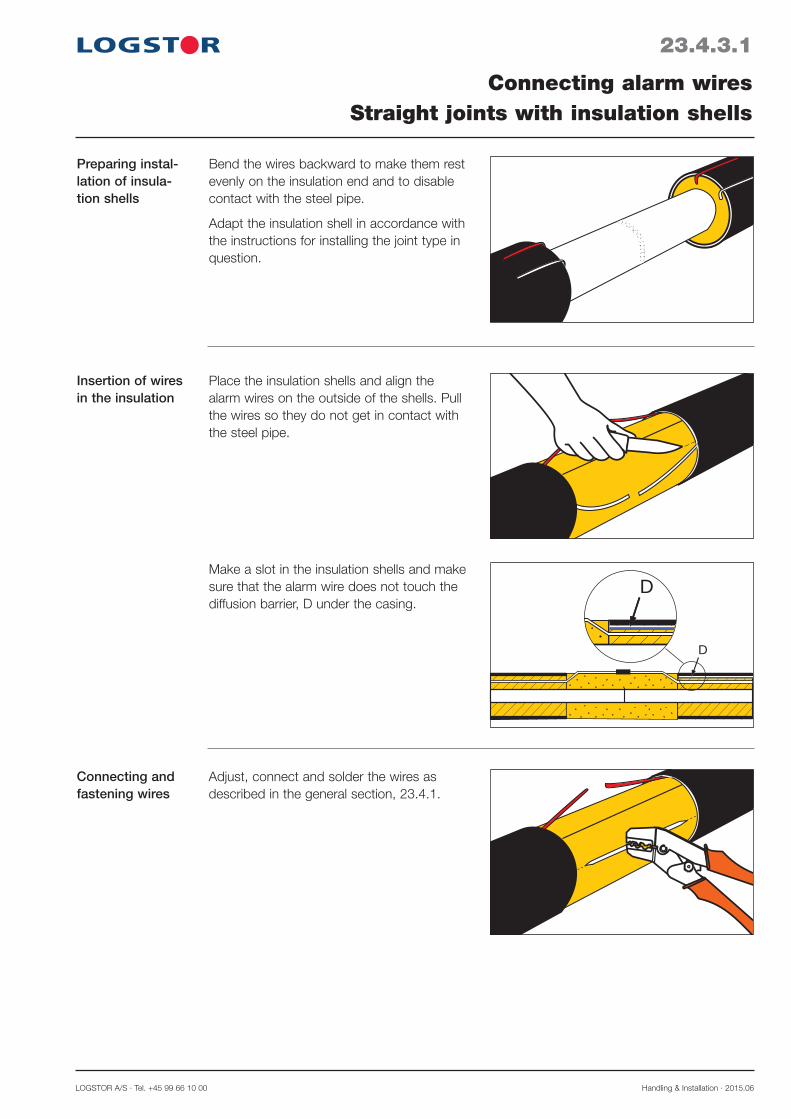
LOGSTOR A/S · Tel. +45 99 66 10 00 Handling & Installation · 2015.06
23.4.3.1
Connecting alarm wiresStraight joints with insulation shells
Preparing instal-lation of insula-tion shells
Connecting and fastening wires
D
D
Bend the wires backward to make them rest evenly on the insulation end and to disable contact with the steel pipe.
Adapt the insulation shell in accordance with the instructions for installing the joint type in question.
Make a slot in the insulation shells and make sure that the alarm wire does not touch the diffusion barrier, D under the casing.
Adjust, connect and solder the wires as described in the general section, 23.4.1.
Place the insulation shells and align the alarm wires on the outside of the shells. Pull the wires so they do not get in contact with the steel pipe.
Insertion of wires in the insulation
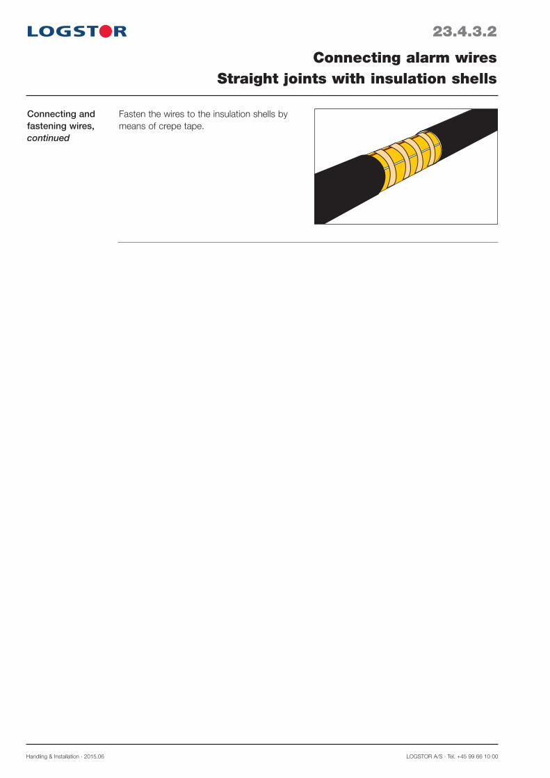
Handling & Installation · 2015.06 LOGSTOR A/S · Tel. +45 99 66 10 00
23.4.3.2
Connecting alarm wiresStraight joints with insulation shells
Connecting and fastening wires,continued
Fasten the wires to the insulation shells by means of crepe tape.
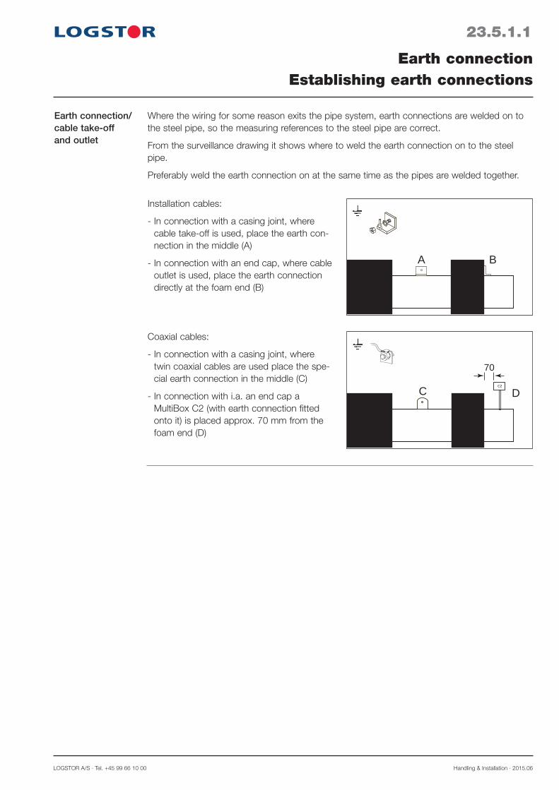
LOGSTOR A/S · Tel. +45 99 66 10 00 Handling & Installation · 2015.06
23.5.1.1
Earth connection/cable take-off and outlet
Earth connectionEstablishing earth connections
Where the wiring for some reason exits the pipe system, earth connections are welded on to the steel pipe, so the measuring references to the steel pipe are correct.
From the surveillance drawing it shows where to weld the earth connection on to the steel pipe.
Preferably weld the earth connection on at the same time as the pipes are welded together.
Installation cables:
- In connection with a casing joint, where cable take-off is used, place the earth con-nection in the middle (A)
- In connection with an end cap, where cable outlet is used, place the earth connection directly at the foam end (B)
A B
Coaxial cables:
- In connection with a casing joint, where twin coaxial cables are used place the spe-cial earth connection in the middle (C)
- In connection with i.a. an end cap a MultiBox C2 (with earth connection fitted onto it) is placed approx. 70 mm from the foam end (D)
C DC2
70

Handling & Installation · 2015.06 LOGSTOR A/S · Tel. +45 99 66 10 00
23.6.0.1
Introduction
Contents
Installing cablesOverview
This section contains instructions for installing installation cables and coaxial cables dependent on the surveillance principle.
Installing installation cables with cable take-off 23.6.1Installing installation cables with cable outlet 23.6.2Installing coaxial cables 23.6.3Relieving and protecting cables 23.6.4 Installing cables and connecting links 23.6.5
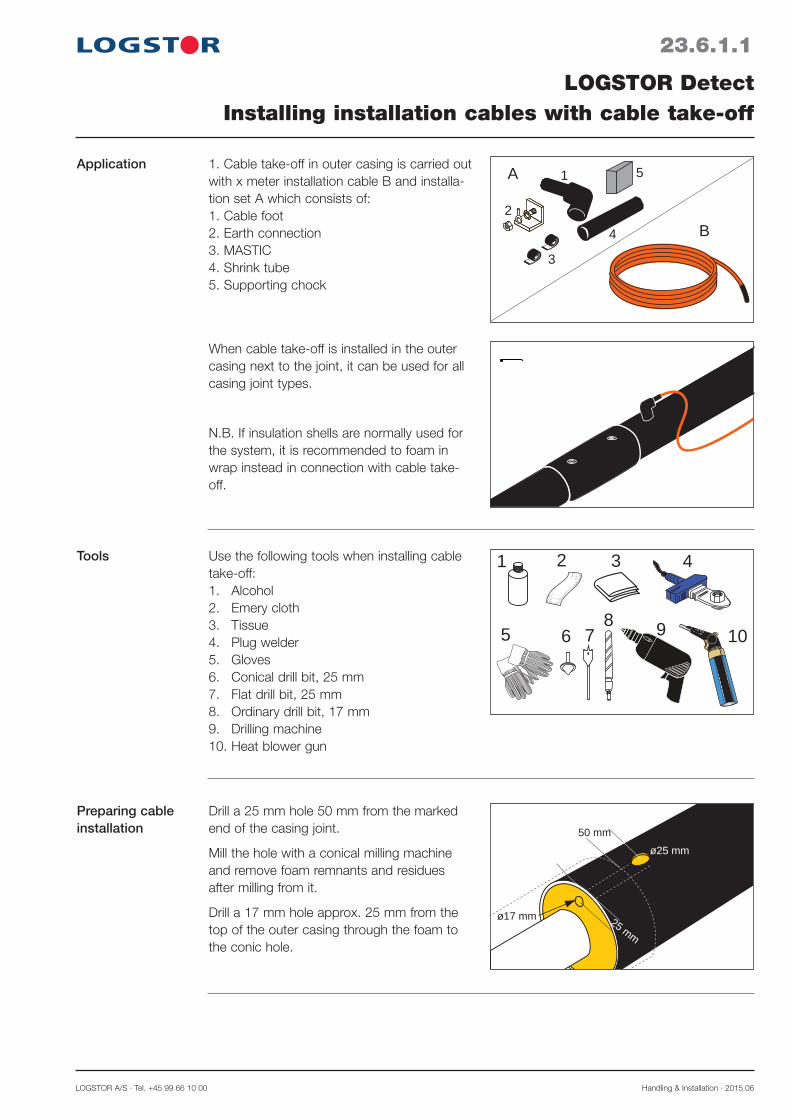
LOGSTOR A/S · Tel. +45 99 66 10 00 Handling & Installation · 2015.06
23.6.1.1
LOGSTOR DetectInstalling installation cables with cable take-off
ApplicationA
B
1
2
4
3
51. Cable take-off in outer casing is carried out with x meter installation cable B and installa-tion set A which consists of: 1. Cable foot2. Earth connection3. MASTIC4. Shrink tube 5. Supporting chock
When cable take-off is installed in the outer casing next to the joint, it can be used for all casing joint types.
N.B. If insulation shells are normally used for the system, it is recommended to foam in wrap instead in connection with cable take-off.
ø25 mm
25 mm
ø17 mm
50 mm
Drill a 25 mm hole 50 mm from the marked end of the casing joint.
Mill the hole with a conical milling machine and remove foam remnants and residues after milling from it.
Drill a 17 mm hole approx. 25 mm from the top of the outer casing through the foam to the conic hole.
Preparing cable installation
1 3
5 7
4
108
6
2
9
Use the following tools when installing cable take-off:1. Alcohol2. Emery cloth3. Tissue4. Plug welder5. Gloves6. Conical drill bit, 25 mm7. Flat drill bit, 25 mm8. Ordinary drill bit, 17 mm9. Drilling machine10. Heat blower gun
Tools

Handling & Installation · 2015.06 LOGSTOR A/S · Tel. +45 99 66 10 00
23.6.1.2
LOGSTOR DetectInstalling installation cables with cable take-off
1. Clean the cable foot and hole edge with alcohol. Grind the cable foot with emery cloth.
2. Preheat the plug welder to 250°C ± 10°C. Heat the cable foot and the hole edge at the same time. When the flat side of the plug welder touches the outer casing and the cable foot has sunk approx. 1 mm, the pressure is relieved approx. 10 seconds.
3. Immediately press the cable foot down.
4. Hold the pressure constant yet soft for 1 minute, until the welding zone is hand-warm.
5. 1-2 weld beads must be visible all around the cable foot.
Welding on cable foot
Earth connection
220 mm
6. It is advantageous to weld the earth con-nection on at the same time as the pipes are welded.
7. Prior to cable installation ensure that the earth connection is rustless.
Installing shrink tube
8. Prior to pulling the cable through the cable foot place the shrink tube on the cable.
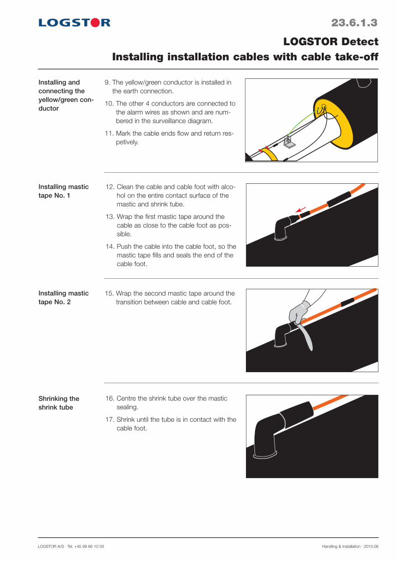
LOGSTOR A/S · Tel. +45 99 66 10 00 Handling & Installation · 2015.06
23.6.1.3
LOGSTOR DetectInstalling installation cables with cable take-off
12. Clean the cable and cable foot with alco-hol on the entire contact surface of the mastic and shrink tube.
13. Wrap the first mastic tape around the cable as close to the cable foot as pos-sible.
14. Push the cable into the cable foot, so the mastic tape fills and seals the end of the cable foot.
Installing mastic tape No. 1
Installing mastic tape No. 2
15. Wrap the second mastic tape around the transition between cable and cable foot.
16. Centre the shrink tube over the mastic sealing.
17. Shrink until the tube is in contact with the cable foot.
Shrinking the shrink tube
9. The yellow/green conductor is installed in the earth connection.
10. The other 4 conductors are connected to the alarm wires as shown and are num-bered in the surveillance diagram.
11. Mark the cable ends flow and return res-petively.
Installing and connecting the yellow/green con-ductor
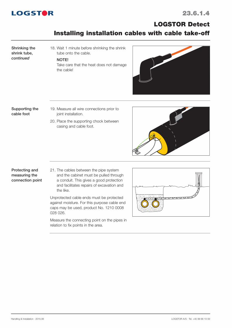
Handling & Installation · 2015.06 LOGSTOR A/S · Tel. +45 99 66 10 00
Supporting the cable foot
19. Measure all wire connections prior to joint installation.
20. Place the supporting chock between casing and cable foot.
21. The cables between the pipe system and the cabinet must be pulled through a conduit. This gives a good protection and facilitates repairs of excavation and the like.
Unprotected cable ends must be protected against moisture. For this purpose cable end caps may be used, product No. 1210 0008 028 026.
Measure the connecting point on the pipes in relation to fix points in the area.
Protecting and measuring the connection point
23.6.1.4
LOGSTOR DetectInstalling installation cables with cable take-off
18. Wait 1 minute before shrinking the shrink tube onto the cable. NOTE! Take care that the heat does not damage the cable!
Shrinking the shrink tube,continued

LOGSTOR A/S · Tel. +45 99 66 10 00 Handling & Installation · 2015.06
23.6.2.1
LOGSTOR DetectInstalling installation cables with cable outlet
Cable outlet at end-cap A
B
4
1
2
3Cable outlet at end-caps is carried out with an installation cable B and an installation set A consisting of:1. Earth connection2. Shrink tubes3. Mastic4. Crimp connectors
1. Weld the earth connection onto the steel pipe close to the insulation. It may be advantageous to weld the pipes at the same time.
2. Fix the cable shoe to the yellow/green conductor with the crimp connector.
Earth connection
3. Install the cable shoe in the earth connec-tion and fasten it securely.
1 2 4
6
3
75 865°
Use the following tools when installing cable outlet at an end-cap:1. Alcohol2. Tissue3. Gloves4. Crimping tool5. Diagonal cutter6. Heat blower gun7. Gas burner, ø 50 mm8. Temperature measuring device
Tools
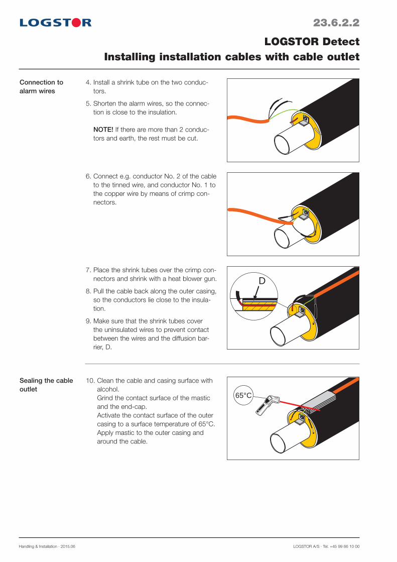
Handling & Installation · 2015.06 LOGSTOR A/S · Tel. +45 99 66 10 00
23.6.2.2
LOGSTOR DetectInstalling installation cables with cable outlet
6. Connect e.g. conductor No. 2 of the cable to the tinned wire, and conductor No. 1 to the copper wire by means of crimp con-nectors.
7. Place the shrink tubes over the crimp con-nectors and shrink with a heat blower gun.
8. Pull the cable back along the outer casing, so the conductors lie close to the insula-tion.
9. Make sure that the shrink tubes cover the uninsulated wires to prevent contact between the wires and the diffusion bar-rier, D.
65°
65°C
10. Clean the cable and casing surface with alcohol. Grind the contact surface of the mastic and the end-cap. Activate the contact surface of the outer casing to a surface temperature of 65°C. Apply mastic to the outer casing and around the cable.
D
Sealing the cable outlet
4. Install a shrink tube on the two conduc-tors.
5. Shorten the alarm wires, so the connec-tion is close to the insulation. NOTE! If there are more than 2 conduc-tors and earth, the rest must be cut.
Connection to alarm wires
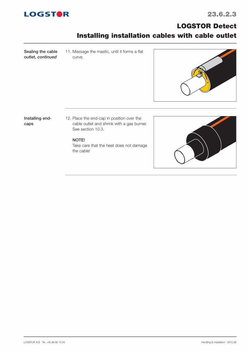
LOGSTOR A/S · Tel. +45 99 66 10 00 Handling & Installation · 2015.06
23.6.2.3
LOGSTOR DetectInstalling installation cables with cable outlet
Installing end-caps
12. Place the end-cap in position over the cable outlet and shrink with a gas burner. See section 10.3. NOTE! Take care that the heat does not damage the cable!
11. Massage the mastic, until it forms a flat curve.
Sealing the cable outlet, continued
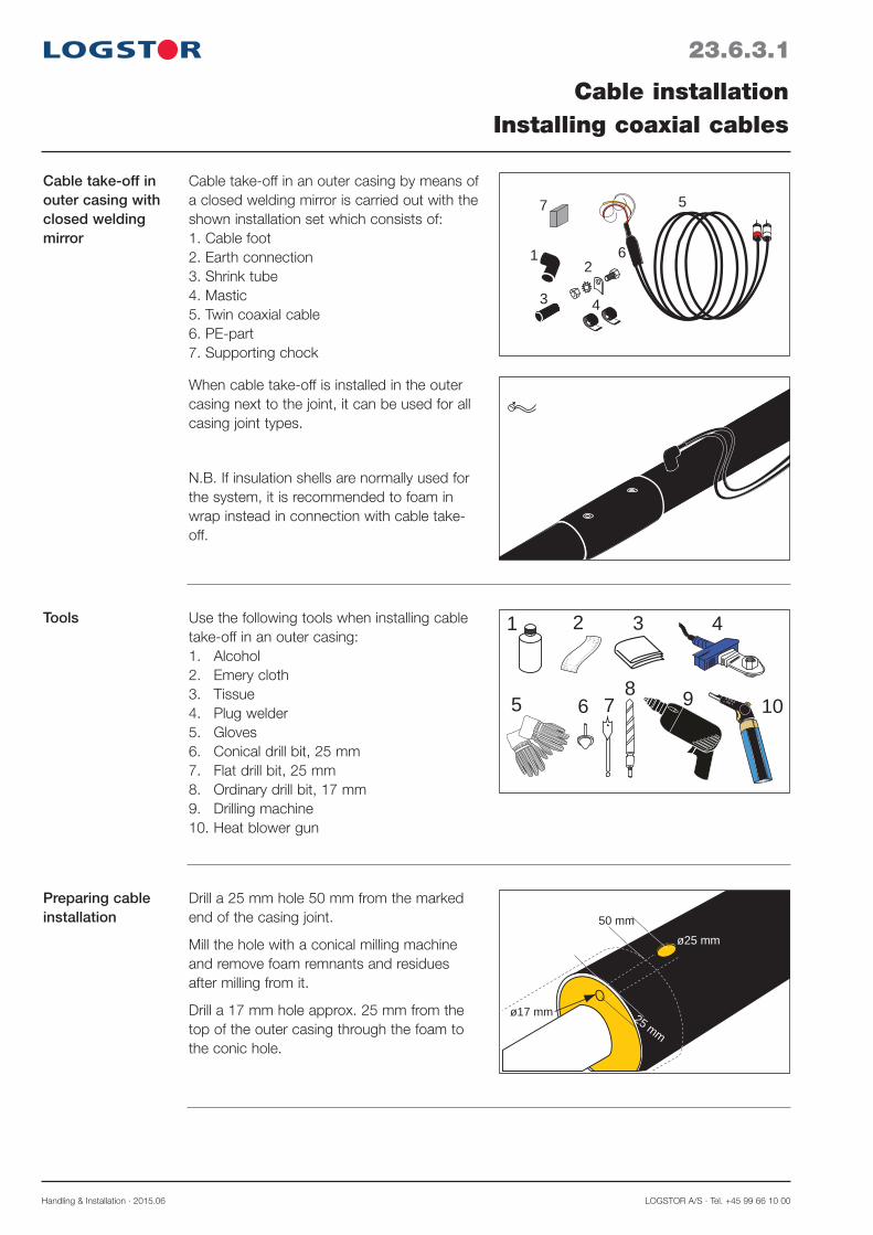
Handling & Installation · 2015.06 LOGSTOR A/S · Tel. +45 99 66 10 00
23.6.3.1
Cable installationInstalling coaxial cables
Cable take-off in outer casing with closed welding mirror
12
43
57
6
Cable take-off in an outer casing by means of a closed welding mirror is carried out with the shown installation set which consists of:1. Cable foot2. Earth connection3. Shrink tube4. Mastic5. Twin coaxial cable6. PE-part7. Supporting chock
When cable take-off is installed in the outer casing next to the joint, it can be used for all casing joint types.
N.B. If insulation shells are normally used for the system, it is recommended to foam in wrap instead in connection with cable take-off.
ø25 mm
25 mm
ø17 mm
50 mm
Drill a 25 mm hole 50 mm from the marked end of the casing joint.
Mill the hole with a conical milling machine and remove foam remnants and residues after milling from it.
Drill a 17 mm hole approx. 25 mm from the top of the outer casing through the foam to the conic hole.
Preparing cable installation
1 3
5 7
4
108
6
2
9
Use the following tools when installing cable take-off in an outer casing:1. Alcohol2. Emery cloth3. Tissue4. Plug welder5. Gloves6. Conical drill bit, 25 mm7. Flat drill bit, 25 mm8. Ordinary drill bit, 17 mm9. Drilling machine10. Heat blower gun
Tools

LOGSTOR A/S · Tel. +45 99 66 10 00 Handling & Installation · 2015.06
23.6.3.2
Cable installationInstalling coaxial cables
Earth connection in casing joint
7. Connect the yellow conductor from the cable foot to the earth connection, which must be free from rust. Tighten the bolt securely.
8. Weld the earth connection, if any, onto the service pipe at the same time as the pipes are welded.
6. Before pulling the cable through the cable foot, place the shrink tube on the cable.
Introducing the cable into the cable foot
1. Clean the cable foot and the hole edge with alcohol. Grind the cable foot with emery cloth.
2. Preheat the plug welder to 250°C ± 10°C. Heat the cable foot and the hole edge at the same time. When the flat side of the plug welder touches the outer casing and the cable foot has sunk approx. 1 mm, the pressure is relieved approx. 10 seconds.Press the cable foot down.
3. Immediately press the cable foot down.
4. Hold the pressure constant yet soft for 1 minute, until the welding zone is hand-warm.
5. There must be 1-2 visible weld beads all around the cable foot.
Welding on cable foot

Handling & Installation · 2015.06 LOGSTOR A/S · Tel. +45 99 66 10 00
14. Place the shrink tube over the end of the cable foot. Shrink until the tube is in contact with both cable foot and the PE-part on the cable. Note! Take care not to damage the cable by exposing it to heat.
15. Measure all wire connections prior to joint installation.
23.6.3.3
Cable installationInstalling coaxial cables
Supporting the cable foot
16. Place a supporting chock between the outer casing and the cable foot.
10. The white and red conductors are con-nected to the tinned and the copper wire, respectively in accordance with the surveillance diagram.
Connecting alarm wires
11. Clean the inside and outside of the cable foot and the PE-part on the cable with alcohol.
12. Grind the cable foot and the PE-part on the cable.
13. Wrap the mastic tape around the PE-part of the cable and push it into the cable foot. Wrap the second mastic tape around the cable foot so the mastic tapes fill and seal the transition between the cable foot and the PE-part.
Sealing cable take-off
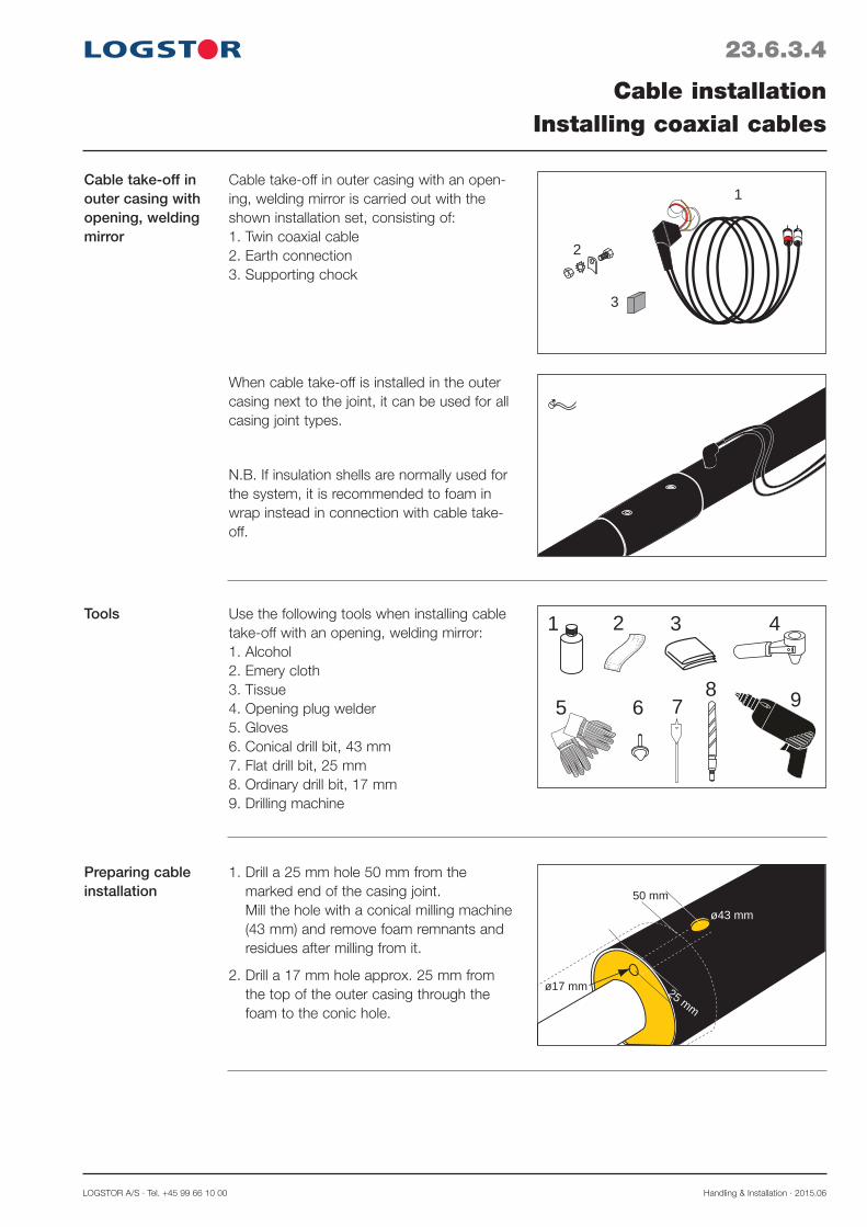
LOGSTOR A/S · Tel. +45 99 66 10 00 Handling & Installation · 2015.06
23.6.3.4
Cable installationInstalling coaxial cables
Cable take-off in outer casing with opening, welding mirror
1
2
3
Cable take-off in outer casing with an open-ing, welding mirror is carried out with the shown installation set, consisting of:1. Twin coaxial cable2. Earth connection3. Supporting chock
When cable take-off is installed in the outer casing next to the joint, it can be used for all casing joint types.
N.B. If insulation shells are normally used for the system, it is recommended to foam in wrap instead in connection with cable take-off.
ø43 mm
25 mm
ø17 mm
50 mm
1. Drill a 25 mm hole 50 mm from the marked end of the casing joint. Mill the hole with a conical milling machine (43 mm) and remove foam remnants and residues after milling from it.
2. Drill a 17 mm hole approx. 25 mm from the top of the outer casing through the foam to the conic hole.
Preparing cable installation
1 3
5 7
4
96
2
8
Use the following tools when installing cable take-off with an opening, welding mirror:1. Alcohol2. Emery cloth3. Tissue4. Opening plug welder5. Gloves6. Conical drill bit, 43 mm7. Flat drill bit, 25 mm8. Ordinary drill bit, 17 mm9. Drilling machine
Tools

Handling & Installation · 2015.06 LOGSTOR A/S · Tel. +45 99 66 10 00
23.6.3.5
Cable installationInstalling coaxial cables
Welding in the cable foot
4. Clean the cable foot with alcohol and grind it with emery cloth.
5. Pull the 3 wires from the cable foot through the hole towards the joint.
6. Connect the plug welder and preheat it to 250°C ± 10°C. Open the plug welder, insert the cable foot, close and heat.
7. When lips of the HDPE-material have melted on the outer casing and cable foot, open the plug welder and press the cable foot down into the melted material. Hold the pressure constant and hard for at least 2 minutes, until the welding zone is handwarm, before releasing your hold of the cable foot. There must be 1-2 visible weld beads all around the cable foot.
8. The white and red conductors are con-nected to the tinned and the copper wire, respectively in accordance with the surveil-lance diagram.
9. The yellow conductor from the cable foot is installed in the earth connection as described above. Tighten the bolt securely.
Connecting alarm wires
3. Weld the earth connection, if any, onto the service pipe at the same time as the pipes are welded. The earth connection must be free from rust.
Earth connection in casing joint

LOGSTOR A/S · Tel. +45 99 66 10 00 Handling & Installation · 2015.06
23.6.4.1
Cable installationRelieving and protecting cables
Relieving and pro-tecting cables
The temperature difference in the pipe sys-tem will result in movements of the pipes.
Consequently, relieve the cable with a U-bend before pulling them to the cabinet.
The cables between the pipe system and the cabinet must be pulled through a conduit. This gives a good protection and facilitates repairs of excavation and the like.
Unprotected cable ends must be protected against moisture. For this purpose cable end caps may be used, product No. 1210 0008 028 026.
Measure the connecting point on the pipes in relation to fix points in the area.

Handling & Installation · 2015.06 LOGSTOR A/S · Tel. +45 99 66 10 00
23.6.5.1
Cable installationInstalling cables and connecting links
Overview Cables to be extended in the earth are con-nected with connecting link and sealed with shrink tubes.
Connection 1. First pull the long shrink tube and then the short shrink tube onto one cable.
2. Mount the couplings of the cables on the connecting link. NOTE! The cable colours must correspond.
3. Clean the contact surface of the shrink tube and center the short shrink tube over the joint.
4. Shrink the tube until it is in contact with the cable and mastic is visible at the ends. Repeat the process with the long shrink tube. NOTE! Take care that the heat does not damage the cable!
Cables to be connected in a cabinet are con-nected with connecting links.
1 32
To install cables and connecting links the fol-lowing tools are used:1. Alcohol2. Gloves3. Heat blower gun
Tools

LOGSTOR A/S · Tel. +45 99 66 10 00 Handling & Installation · 2015.06
Transition from coaxial cable to installation cable
1233
To be used when Detector X1L is connected to coaxial cables.
23.6.5.2
Cable installationInstalling cables and connecting links

Handling & Installation · 2015.06 LOGSTOR A/S · Tel. +45 99 66 10 00
23.7.0.1
Introduction
Contents
Connection and coupling boxesOverview
This section contains installation instructions for connecting boxes and cables dependent on the surveillance principle.
Coupling in connection with installation cables 23.7.1Coupling in connection with coaxial cables 23.7.2
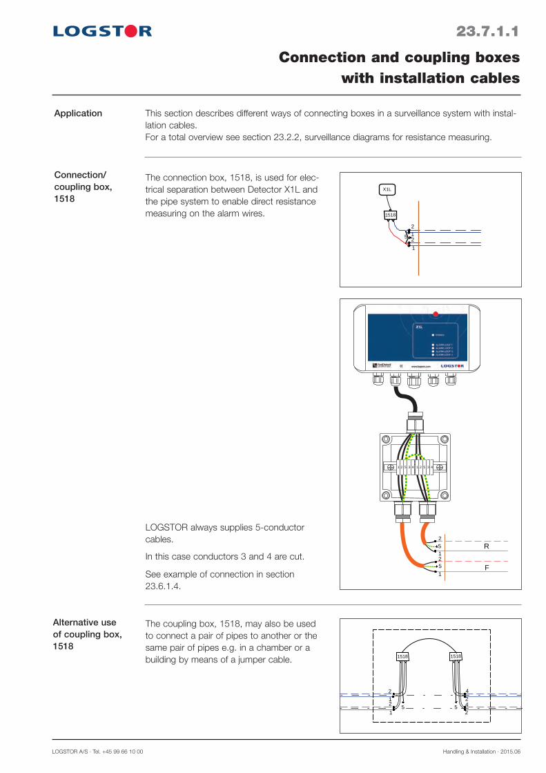
LOGSTOR A/S · Tel. +45 99 66 10 00 Handling & Installation · 2015.06
23.7.1.1
Application
Connection/ coupling box, 1518
Connection and coupling boxeswith installation cables
1518
2
2
1
1
5
X1L
This section describes different ways of connecting boxes in a surveillance system with instal-lation cables.For a total overview see section 23.2.2, surveillance diagrams for resistance measuring.
The connection box, 1518, is used for elec-trical separation between Detector X1L and the pipe system to enable direct resistance measuring on the alarm wires.
2
2
1
1
5
R
F
5
1 2 5 3 4 1 2 5 3 4
See example of connection in section 23.6.1.4.
LOGSTOR always supplies 5-conductor cables.
In this case conductors 3 and 4 are cut.
Alternative use of coupling box, 1518
42
1 2
2
42
1
1518
5 5
1518
The coupling box, 1518, may also be used to connect a pair of pipes to another or the same pair of pipes e.g. in a chamber or a building by means of a jumper cable.

Handling & Installation · 2015.06 LOGSTOR A/S · Tel. +45 99 66 10 00
23.7.1.2
Terminal box, 1517
Box 1517 at the start/end of a system
Connection and coupling boxeswith installation cables
1517
2
2
1
1
5
2
1
1
21
2
1517
5
5
R
F
The terminal box, 1517, can be used:
- at the beginning and the end of a system - as a measuring point along the system - as a terminal box between two circuits in e.g. a transmission line.
For a total overview see section 23.2.2, surveillance diagrams for resistance measuring.
The terminal box, 1517, used as a measuring point of a pair of pipes in:
- a building - a chamber
- a cabinet
2
2
1
1
5
R
F
5
F R
1 2 5 3 4 1 2 5 3 4Loops: 1-2
LOGSTOR always supplies 5-conductor cables.
In this case conductors 3 and 4 are cut.
See example of connection in section 23.6.1.4.
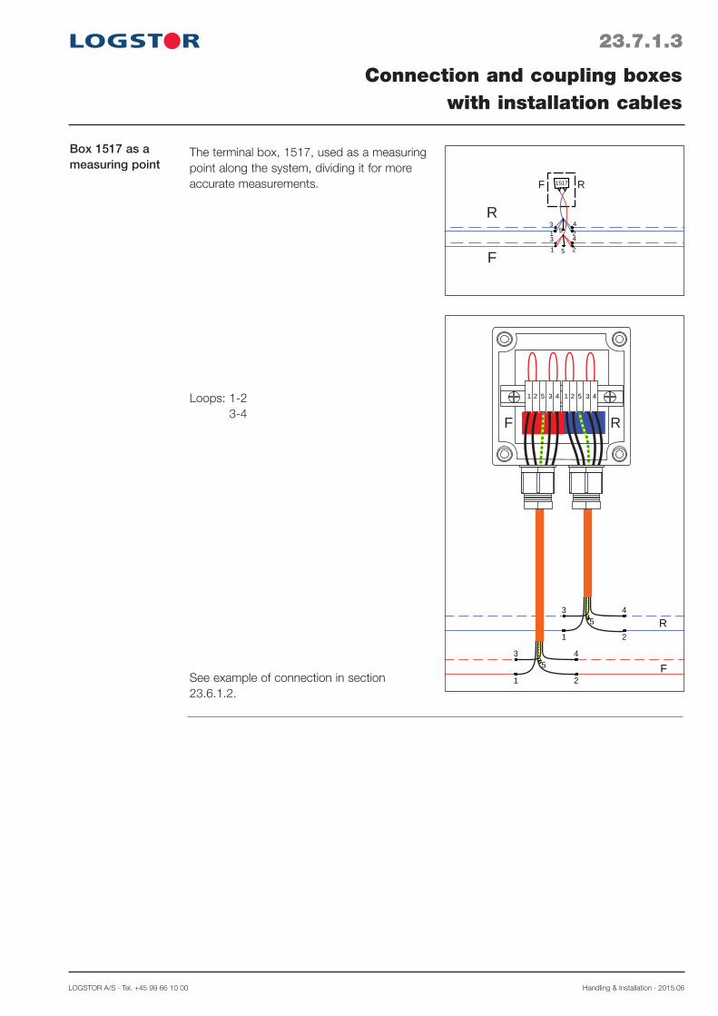
LOGSTOR A/S · Tel. +45 99 66 10 00 Handling & Installation · 2015.06
23.7.1.3
Box 1517 as a measuring point
Connection and coupling boxeswith installation cables
43
1 2
2
43
1
1517
5
5
R
F
RF
The terminal box, 1517, used as a measuring point along the system, dividing it for more accurate measurements.
4
R
F
5
3
1 2
45
3
1 2
F R
1 2 5 3 4 1 2 5 3 4Loops: 1-2 3-4
See example of connection in section 23.6.1.2.
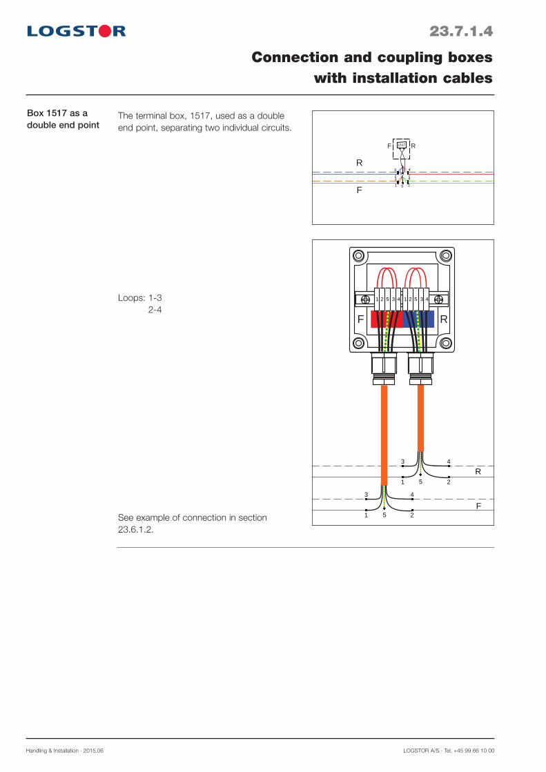
Handling & Installation · 2015.06 LOGSTOR A/S · Tel. +45 99 66 10 00
23.7.1.4
Connection and coupling boxeswith installation cables
Box 1517 as a double end point
43
1 2
2
43
1
1517
5
5
R
F
RF
The terminal box, 1517, used as a double end point, separating two individual circuits.
4
R
F
5
3
1 2
4
5
3
1 2
F R
1 2 5 3 4 1 2 5 3 4Loops: 1-3 2-4
See example of connection in section 23.6.1.2.

LOGSTOR A/S · Tel. +45 99 66 10 00 Handling & Installation · 2015.06
23.7.2.1
MultiBox C2 is used when connecting Detector X4 and when a jumper cable is installed in cellars or dry inspection cham-bers and when terminating circuits.
Installation in connection with end-cap
Connection/coupling boxInstallating box for coaxial cables
70 mm
MultiBox C2
DPlace a piece of sealing strip or mastic on the end-cap prior to installation.
Shorten the wires from the pipe and extend them with insulated wires.
Make sure that the uninsulated wire does not get in contact with the diffusion barrier. Use shrink or flex tubes
Press the straightened wire into the sealing strip or mastic.
Shrink the end-cap.
Weld the earth connection on MultiBox C2, 70 mm from the outer casing end.
Adjust the earth connection to raise the box above the insulation.
Fix the wires from the pipe to the two screws on the side of MultiBox C2.
Connect the coaxial cables to MultiBox C2 by means of BNC connectors.

Handling & Installation · 2015.06 LOGSTOR A/S · Tel. +45 99 66 10 00
23.8.0.1
Introduction
Contents
Surveillance componentsOverview
This section contains installation instructions for the various detectors dependent on the sur-veillance principle.
Surveillance component for resistance measuring 23.8.1Surveillance component for impedance measuring 23.8.2

LOGSTOR A/S · Tel. +45 99 66 10 00 Handling & Installation · 2015.06
23.8.1.1
Surveillance components Resistance measuring
Detector X1LDescription
For resistance measuring the detector, type X1L is used.
X1L is available in 4 designs dependent on the pipe system and the requirements to the surveillance.
It must be installed in a condensation free environment indoors or in a weatherproof cabinet.
Standard properties: - 4 circuits (exits/channels), each with a range of 7000 m on alarm wires, which are always in loop (3500 m pipe)
- Can emit a visual as well as an acoustic signal, if the detection level is exceeded
- Is factory-set to a detection level of 300 kΩ
- The level can be adjusted from 1 kΩ to 1 MΩ
- Enclosure class: IP 67
- Ready for connection to 110/230 V by means of the included, preinstalled trans-former.
Weight: 0.5 kg
Dimensions: L x W x H: 200 x 110 x 60 mm
Range: 4 x 7,000 m wires, 8 channels (4 loops)
Measurement range - insulation: 1kΩ - 1 MΩ
Alarm transmitter: Optical and acoustic - and with XTool software, relay out-put
Signal: Network, GPRS, fibre
Enclosure: Polycarbonate, halogen-free - IP 67
Range of application: -20°C to +70°C
Power supply: Transformer 110/230 V AC, 12 V DC - or battery
Power consumption: < 50 mA
Placement: It is recommended to place it in a dry and frostfree environment
CE approved
Specifications

Handling & Installation · 2015.06 LOGSTOR A/S · Tel. +45 99 66 10 00
23.8.1.2
Surveillance components Resistance measuring
Diagram with connections and functions
F1
110/230V~ 50/60 Hz
110/230V~ 50/60 Hz
X1L diagram (X1L-G, X1L-BG) with GPRS functionality. External XPort for LAN connection.
F1
110/230V~ 50/60 Hz
110/230V~ 50/60 Hz
X1L diagram (X1L) without GPRS functionality. Built-in XPort for LAN connection.

LOGSTOR A/S · Tel. +45 99 66 10 00 Handling & Installation · 2015.06
23.8.1.3
Surveillance components Resistance measuring
Notation Terminal Pin Wiring Comment
Power T11 2
+ -
Primary: 110-230 VAC, secondary: 12 VDC Battery, Lithium 7.2 VDC, 13 Ah
Relay T23 4 5
NO, normally open COM
NC, normally closed
Max. load 30 VDC, 1A, 125 VAC, 300 mA
Resistance alarm loop
T3
6 7
Alarm loop 1Return Flow
8 Earth Service pipe
9 10
Alarm loop 2 Retun
Return
Resistance alarm loop
T4
11 12
Alarm loop 3Return Flow
13 Earth Service pipe
1415
Alarm loop 4 Return
Return
WakeUp T5
17 1819 20
NO NO NO NO
WakeUp inputs
Diagram with connections and functions, continued

Handling & Installation · 2015.06 LOGSTOR A/S · Tel. +45 99 66 10 00
23.8.2.1
Surveillance components Impedance measuring
Detector X4 Description
For impedance measuring the detector, type X4 is used.
Product No. 8000 0000 007 024
It must be installed in a condensation free environment indoors or in a weatherproof cabinet with thermostat and heating element.
Standard properties: - X4 has a built-in transformer, 110/230 V - 4 circuits (exits/channels), each with a range of 5000 m on alarm wires. That equals 5000 m pipe, provided that a single wire - not a loop - has been used from the measurement box to the end of the surveilled section.
- The connected pipe section to be measured is surveilled at preset intervals by the built-in TDR pulse reflectometer
- Measuring accuracy: < 1 m
- Enclosure class: IP 53
- Measuring range: 1 kΩ to 50 MΩ
- All data are stored in the memory
- If a fault is detected, a curve of the ongoing course is automatically generated. This curve can be transmitted to the surveillance computer
- Standard network connection: LAN
- X4 communicates via a GPRS modem (to be purchased separately) or via broadband
- The LCD display i.a. shows: - Wire resistance, Ω - Alarm signal - Date, time - Error voltage
For installation and protection of detectors and other components like transient protec-tions, transformers, GPRS modems, anten-nas, heating elements, temperature gauges etc.
L x W x H: 380 x 380 x 210
Enclosure class: IP 66.
Product No. 8000 0000 007 010
Detector cabinet

LOGSTOR A/S · Tel. +45 99 66 10 00 Handling & Installation · 2015.06
23.8.2.2
Surveillance componentsImpedance measuring
Weight: 2 kg
Dimensions: L x W x H: 260 x 150 x 90 mm
Range: 4 x 5,000 m wires, 4 channels (2 loops or open)
Measurement range - insulation: 1kΩ - 50 MΩ
Alarm transmitter: Optical and acoustic - and with XTool software, relay out-put
Communication protocol: TCP/IP Accuracy: < 1 m, Impulse: TDR 1-5ns
Signal: Network, GPRS, fibre
Enclosure: Aluminium IP 53 (with component cabinet IP 66)
Range of application: -20°C to +80°C
Power supply: Built-in transformer 110/230 V AC, 12 V DC
Power consumption: 15 W
Placement: Condensation free - indoors or in a weatherproof cabinet
CE approved
Specifications
Diagram with connections and functions
110/230V~ 50/60 Hz
X4 diagram

Handling & Installation · 2015.06 LOGSTOR A/S · Tel. +45 99 66 10 00
Notation Pin Wiring Comment
Leak detection
1 234
Channel 1/Coaxial 1Channel 2/Coaxial 2Channel 3/Coaxial 3Channel 4/Coaxial 4
Coaxial cable RG62 A/U 93 Ω
Analogue inputs
5/6 7/8 9/10 11/12
Analogue input 1 Analogue input 2 Analogue input 3 Analogue input 4
Analogue inputs 4-20 mA ± 0.1 V
Relay 131415
NO/normally openCOM
NC/normally closedMax. load 24 VDC, 2A
Primary powerLNPE
AC 230 VACAC 230 VAC
Earth
Secondary power COM +V2
12 VDC 12 VDC
E.g. an external modem
Diagram with connections and functions, continued
23.8.2.3
Surveillance componentsImpedance measuring
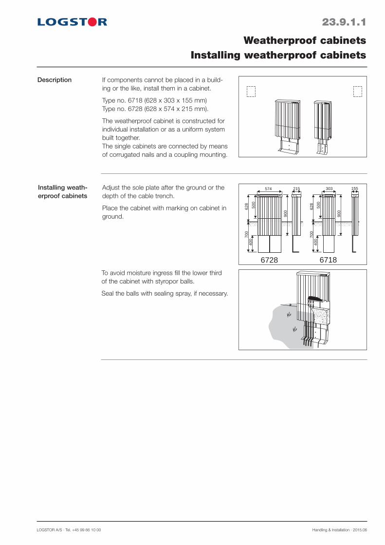
LOGSTOR A/S · Tel. +45 99 66 10 00 Handling & Installation · 2015.06
23.9.1.1
Description
Installing weath-erproof cabinets
Weatherproof cabinetsInstalling weatherproof cabinets
574 215
900
500
628
700
400
303 155
900
500
628
700
400
6728 6718
If components cannot be placed in a build-ing or the like, install them in a cabinet.
Type no. 6718 (628 x 303 x 155 mm)Type no. 6728 (628 x 574 x 215 mm).
The weatherproof cabinet is constructed for individual installation or as a uniform system built together.The single cabinets are connected by means of corrugated nails and a coupling mounting.
Adjust the sole plate after the ground or the depth of the cable trench.
Place the cabinet with marking on cabinet in ground.
To avoid moisture ingress fill the lower third of the cabinet with styropor balls.
Seal the balls with sealing spray, if necessary.

Handling & Installation · 2015.06 LOGSTOR A/S · Tel. +45 99 66 10 00
For surveillance of chambers, low-lying areas etc. Detector A1e is used.
The unit has 12 separate entry points and can i.a. register: - moisture - temperature - water level - velocity of incoming water - pressure and temperature in the insulated pipes
In addition A1e has the same functions as X1L for resistance measuring alarm wires in preinsulated pipe systems. For this purpose A1e has two circuits with a range of 5000 m each (2500 m pipes in loop).
Detector A1eDescription
23.10.0.1
LOGSTOR Detect Surveillance of chambers
Diagram with connections and functions
110/230V~ 50/60 Hz
110/230V~ 50/60 Hz
A1e diagram (A1e-G, A1e-BG) with GPRS functionality. External XPort for LAN connection.
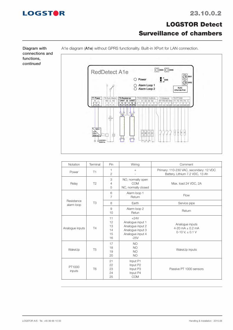
LOGSTOR A/S · Tel. +45 99 66 10 00 Handling & Installation · 2015.06
Notation Terminal Pin Wiring Comment
Power T11 2
+ -
Primary: 110-230 VAC, secondary: 12 VDC Battery, Lithium 7.2 VDC, 13 Ah
Relay T23 4 5
NO, normally open COM
NC, normally closed
Max. load 24 VDC, 2A
Resistance alarm loop
T3
6 7
Alarm loop 1Return Flow
8 Earth Service pipe
9 10
Alarm loop 2 Retun
Return
Analogue inputs T4
11 1213141516
+24VAnalogue input 1Analogue input 2 Analogue input 3 Analogue input 4
-25V
Analogue inputs 4-20 mA ± 0.2 mA
0-10 V, ± 0.1 V
WakeUp T5
17 1819 20
NO NO NO NO
WakeUp inputs
PT1000 inputs
T6
2122232425
Input P1Input P2Input P3Input P4
COM
Passive PT 1000 sensors
23.10.0.2
LOGSTOR Detect Surveillance of chambers
Diagram with connections and functions,continued
110/230V~ 50/60 Hz
110/230V~ 50/60 Hz
A1e diagram (A1e) without GPRS functionality. Built-in XPort for LAN connection.


LOGSTOR A/S · Tel. +45 99 66 10 00 Handling & Installation · 2013.02
24.0.0.1
ToolsOverview
Contents
Introduction
Tools, general 24.1Installation equipment for weld joints 24.2Tools for shrink joints 24.3Tools for on-site curved pipes 24.4Tools for FlexPipes 24.5Hot tapping tools 24.6Tools for the surveillance system 24.7Tools for valve arrangements 24.8
For our pipe systems auxiliary tools facilitating the installation are available.


LOGSTOR A/S · Tel. +45 99 66 10 00 Handling & Installation · 2013.02
24.1.0.1
ToolsGeneral
Knife
Scraper
Saw
Cutting pipes and removing insula-tion
For correct cutting of pipes and removal of insulation LOGSTOR offers some simple, effective tools.
A sharp knife can be used to remove foam remnants and wet foam in the pipe ends.
Knife, type No. 1950.
When altering pipes and installing branches part of the outer casing and the insulation material are removed.
The scraper removes residual foam on the service pipe.
Scraper, product No. 9050 0000 043 000.
Extra cutting edges, product No. 9050 0000 043 001.
When cutting pipes with copper wires a saw with depth guard, preventing damage to the wires, is used.
Used without depth guard to cut insulation shells.
Component No. 9000.
Marker White waterproof marker to mark the casing pipe.
Component No. 9050

Handling & Installation · 2013.02 LOGSTOR A/S · Tel. +45 99 66 10 00
24.1.0.2
ToolsGeneral
Leakage testing
Shrinking
Installing E-Comps
To shrink end-caps and shrink sleeves and preheat/seal joints and joint locations a gas burner set is used.
See section 24.3: Tools for shrink joints.
Before welding the E-Comp into the system, the e-measurement is adjusted by means of a compression tool and the muff is tack welded.
Steel pipe ø out. mm Product No.
The pressure testing equipment is used to leakage test BandJoints. It is supplied in a practical carrying case, product No. 9050 0000 027 011.
Pressure testing equipment can also be used to leakage test welds on E-Comps.
48.3-168.3 9050 0000 044 000 219.1-323.9 9050 0219 045 000 355.6-508 9050 0000 044 001
To leakage test SX-, EW-, B2S-, and BSJoints a hand pump is used.
Product No. 9050 0000 027 000.

LOGSTOR A/S · Tel. +45 99 66 10 00 Handling & Installation · 2013.02
24.2.0.1
ToolsInstallation equipment for weld joints
BandJoint ø 225-800 mm
BandJoint ø 90-200 mm
Introduction This section describes the installation equipment to be used when welding different dimensions of electro-welded casing joints.
Electro-welded casing joints must only be installed by certified fitters, trained at the LOGSTOR Training Centre.
2
1 3
The complete welding process is controlled by the welding machine (400 V) which auto-matically checks that the welding tempera-ture and the applied pressure on the joint faces are maintained correctly.
The welding method requires a mechanical welding pressure and a computer-controlled welding machine (230 V).
For the installation work LOGSTOR provides a fully equipped trailer containing generator, compressor, pressure bands, cover sheets and all necessary tools in specific tool boxes.
When installing, the following installation equipment is used:1. Pressure bands2. All the necessary tools in a combined plug
and installation box3. Cover sheet

Handling & Installation · 2013.02 LOGSTOR A/S · Tel. +45 99 66 10 00
24.2.0.2
ToolsInstallation equipment for weld joints
BandJoint ø 900-1400 mm
The complete welding process is controlled by a welding machine (400 V) which auto-matically check that the welding temperature and the applied pressure on the joint faces are maintained correctly.
For the installation work LOGSTOR provides a fully equipped trailer containing genera-tor, compressor, pressurve bands, cover sheets and all necessary tools in specific tool boxes.
EWJoint ø 200-1400 mm
This welding method requires a mechanical welding pressure and a computer-controlled welding machine (230/400V).
Use staples to fix the welding strips.
Outer casing Product No. Staple size
ø 90-ø 400 9050 0000 031 053 13-4 mm
≥ ø 450 9050 0000 031 052 140-6 mm
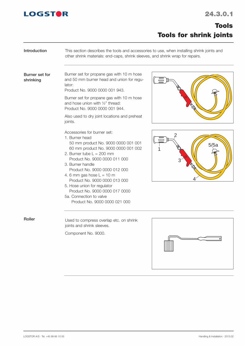
LOGSTOR A/S · Tel. +45 99 66 10 00 Handling & Installation · 2013.02
24.3.0.1
ToolsTools for shrink joints
Introduction This section describes the tools and accessories to use, when installing shrink joints and other shrink materials: end-caps, shrink sleeves, and shrink wrap for repairs.
Roller Used to compress overlap etc. on shrink joints and shrink sleeves.
Component No. 9000.
Burner set for shrinking
Burner set for propane gas with 10 m hose and 50 mm burner head and union for regu-lator: Product No. 9000 0000 001 943.
Burner set for propane gas with 10 m hose and hose union with ½” thread: Product No. 9000 0000 001 944.
Also used to dry joint locations and preheat joints.
1
2
3
4
5/5a
Accessories for burner set:1. Burner head
50 mm product No. 9000 0000 001 001 60 mm product No. 9000 0000 001 002
2. Burner tube L = 200 mm Product No. 9000 0000 011 000
3. Burner handle Product No. 9000 0000 012 000
4. 6 mm gas hose L = 10 m Product No. 9000 0000 013 000
5. Hose union for regulator Product No. 9000 0000 017 0000
5a. Connection to valve Product No. 9000 0000 021 000

Handling & Installation · 2013.02 LOGSTOR A/S · Tel. +45 99 66 10 00
Welding mirror Welding mirror with interchangeable cones for welding plugs. Product No. 9050 0000 023 013
Product Nos. of cones for: - 35 mm welding plug: 9050 0000 023 010 - 43 mm welding plug: 9050 0000 023 011
24.3.0.2
ToolsTools for shrink joints

LOGSTOR A/S · Tel. +45 99 66 10 00 Handling & Installation · 2013.02
24.4.0.1
ToolsTools for on-site curved pipes
Bending tool
Introduction This section presents the tools, used in connection with on-site curved pipes.
R
To bend district heating pipes ø 26.9-88.9 mm for on-site curved pipes 4 different tools are available.
Tool Primary field of Radius Product No. No. application mm m 1 26. 9 2. 9 9050 0000 019 001 2 33. 7-42. 4 3. 8 9050 0000 019 002 3 48. 3-60. 3 5. 1 9050 0000 019 003 4 76. 1-88. 9 6. 5 9050 0000 019 004
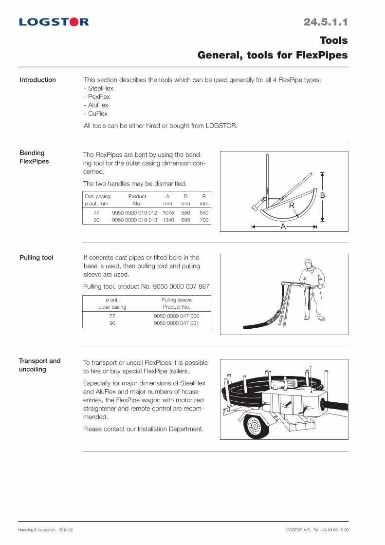
Handling & Installation · 2013.02 LOGSTOR A/S · Tel. +45 99 66 10 00
24.5.1.1
ToolsGeneral, tools for FlexPipes
Bending FlexPipes
Introduction This section describes the tools which can be used generally for all 4 FlexPipe types:- SteelFlex- PexFlex- AluFlex- CuFlex
All tools can be either hired or bought from LOGSTOR.
A
BR
The FlexPipes are bent by using the bend-ing tool for the outer casing dimension con-cerned.
The two handles may be dismantled.
Out. casing Product A B R ø out. mm No. mm mm mm
77 9050 0000 019 012 1075 550 550 90 9050 0000 019 013 1340 695 700
Pulling tool If concrete cast pipes or tilted bore in the base is used, then pulling tool and pulling sleeve are used.
Pulling tool, product No. 9050 0000 007 887
ø out. Pulling sleeve outer casing Product No.
77 9050 0000 047 000 90 9050 0000 047 001
Transport and uncoiling
To transport or uncoil FlexPipes it is possible to hire or buy special FlexPipe trailers.
Especially for major dimensions of SteelFlex and AluFlex and major numbers of house entries, the FlexPipe wagon with motorized straightener and remote control are recom-mended.
Please contact our Installation Department.

LOGSTOR A/S · Tel. +45 99 66 10 00 Handling & Installation · 2013.02
24.5.2.1
ToolsTools for SteelFlex pipes
Introduction This section describes the tools which are especially used in connection with SteelFlex pipes.
SteelFlex pipes are welded, so there is no special installation equipment for these pipes.

Handling & Installation · 2013.02 LOGSTOR A/S · Tel. +45 99 66 10 00
24.5.3.1
ToolsTools for PexFlex pipes
Installation equip-mentJoints
Introduction This section describes the tools which are used especially in connection with Pexflex pipes.
12
3
4
6 7
8
5
When installing compression couplings for PexFlex pipes a tool set, containing com-pression tool and accessories for PEX-service pipe dimensions ø 16, 22, 25, 28, 32, 40 and 50 mm, is used. Available in sturdy carrying case, product No. 0500 0000 002 006.
1. Compression tool2. Exchangeable compression inserts3. Saw4. Plastic pipe cutter for ≤ ø 40 mm5. Plastic pipe cutter for ≤ ø 63 mm6. Stripping knife7. Deburring tool8. Special lubricating grease
For the installation a hydraulic pump must also be used.
Component No. 0520.
Alternative strip-ping tools
Stripping tools: a. PEX ø 20-50 mm b. PEX ø 63-110 mm
Component No. 9000.

LOGSTOR A/S · Tel. +45 99 66 10 00 Handling & Installation · 2013.02
24.5.4.1
ToolsTools for AluFlex pipes
Hydraulic pump
Introduction This section describes the tools which are used especially in connection with AluFlex pipes.
1
2
Carrying case for hydraulic pump, type No. 91630.
Contents: 1. Hydraulic pump, complete2. Bottle with reserve oil.
Compression tool for service pipe dimensions ø 20-32 mm
12
3
4
6
78
5
Sturdy carrying case for compression tool and accessories for service pipe dimensions ø 20, ø 26 and ø 32 mm.
Available in sturdy carrying case, product No. 0500 0000 002 005.
Contents: 1. Compression tool2. Exchangeable compression inserts3. Hacksaw, type No. 916824. Pipe cutter5. Stripping knife, type No. 915036. Deburring tool, internal; type No. 916447. Deburring tool, external; type No. 915518. Special lubricating agent, type No. 91685
Bending spring Bending springs are used when bending AluFlex pipes.
ø out. AluFlex Product No.
20 9050 0020 046 000 26 9050 0026 046 000 32 9050 0032 046 000

Handling & Installation · 2013.02 LOGSTOR A/S · Tel. +45 99 66 10 00
24.5.4.2
ToolsTools for AluFlex pipes
Auxiliary tools, 90° bending
Bending tool for 90° bending in connec-tion with external wall penetration of AluFlex pipe.
The bending tool is used together with bending spring.
ø out. outer casing Type No.
77 41557 90 41558

LOGSTOR A/S · Tel. +45 99 66 10 00 Handling & Installation · 2013.02
24.5.5.1
ToolsTools for CuFlex and the copper pipe system
Introduction This section presents the tools which are especially used in connection with CuFlex pipes.
If the CuFlex pipes are joined by means of compression fittings, the same tools as for PexFlex are used, see section 24.5.3.
Compression coupling
Calibration tool Tool set for calibration of the copper pipe ends. The set consists of a mandrel (internal) and a ring (external).
28/25
15 9050 0000 017 000 22 9050 0000 017 001 28 9050 0000 017 002 35 9050 0000 017 003 42 9050 0000 017 004 54 9050 0000 017 006 70 9050 0000 017 007 89 9050 0000 017 008
Copper pipe Calibration set ø out. mm Product No.
Locksaw
Retaining tool for saddle pipe piece
Use locksaw when branching with saddle pipe piece.
Holder for locksaw, product No. 9050 0000 023 002.
Use retaining tool, type No. 2573, to fix the saddle pipe piece during soldering.
1
2 18 2561 17 22 2562 21 28 2564 27
Copper pipe Locksaw ø out. ø mm Type No. mm

Handling & Installation · 2013.02 LOGSTOR A/S · Tel. +45 99 66 10 00
24.5.5.2
ToolsTools for CuFlex and the copper pipe system
Bending spring
Auxiliary tools, 90° bending
Bending springs are used when bending CuFlex pipes.
Bending tool for 90° bending in connection with external wall penetration.Bending tool must be used together with bending spring.
ø out. CuFlex Type No.
ø out. outer casing Type No.
18 16865 22 16866 28 16867
77 41557 90 41558
90 16347 90-160 1978
Outer casing Bending tool ø out. mm Type No.
Bending tool for the copper pipesystem
1.3 m
R
R = 0.7 m16347For on-site curved pipes two different bend-ing tools are available.
R = 1.20 m
1.5 m1978
Bending tool for CuFlex, see section 24.6.1
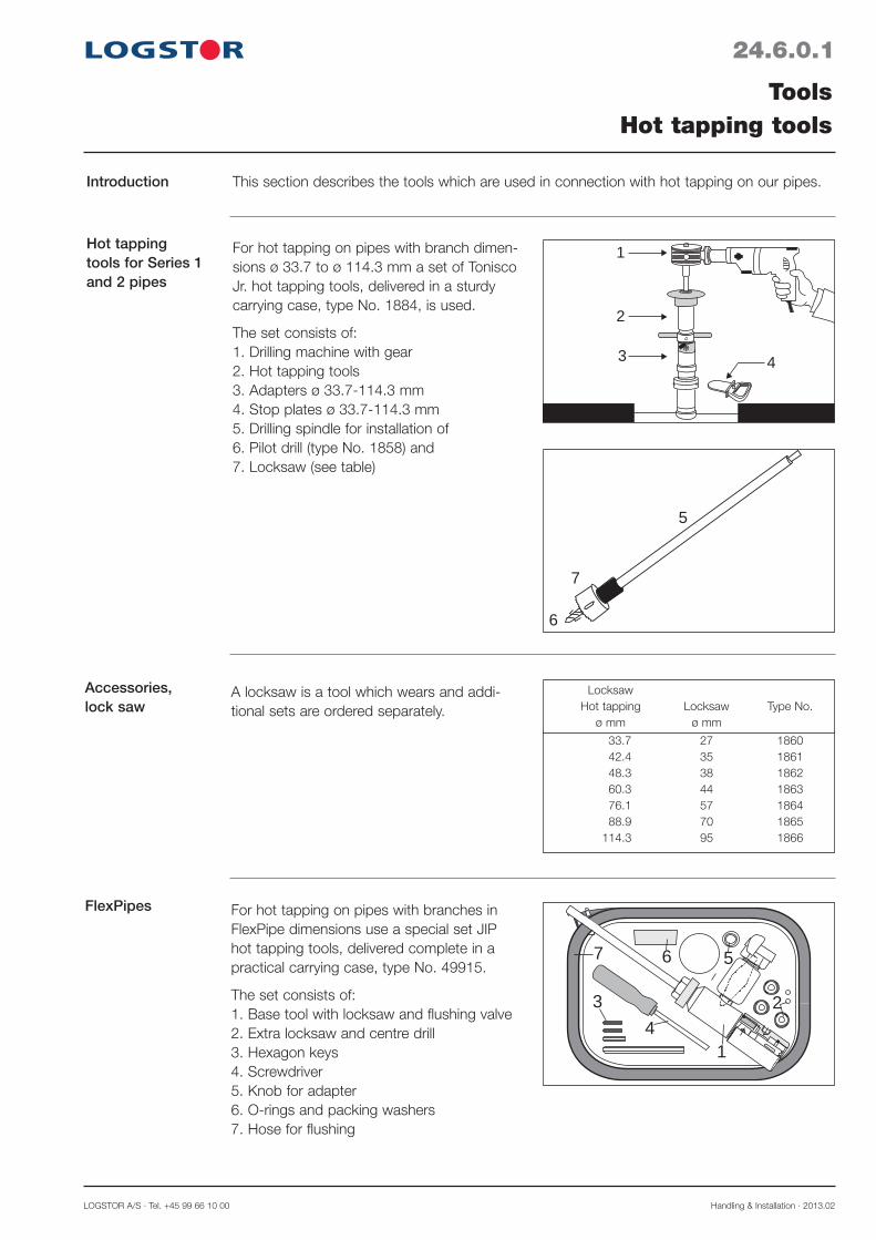
LOGSTOR A/S · Tel. +45 99 66 10 00 Handling & Installation · 2013.02
FlexPipes
7 6 5
2
14
3
For hot tapping on pipes with branches in FlexPipe dimensions use a special set JIP hot tapping tools, delivered complete in a practical carrying case, type No. 49915.
The set consists of:1. Base tool with locksaw and flushing valve2. Extra locksaw and centre drill3. Hexagon keys4. Screwdriver5. Knob for adapter6. O-rings and packing washers7. Hose for flushing
Accessories,lock saw
A locksaw is a tool which wears and addi-tional sets are ordered separately.
33.7 27 1860 42.4 35 1861 48.3 38 1862 60.3 44 1863 76.1 57 1864 88.9 70 1865 114.3 95 1866
Locksaw Hot tapping Locksaw Type No. ø mm ø mm
Hot tapping tools for Series 1 and 2 pipes
1
3 4
2
6
7
5
For hot tapping on pipes with branch dimen-sions ø 33.7 to ø 114.3 mm a set of Tonisco Jr. hot tapping tools, delivered in a sturdy carrying case, type No. 1884, is used.
The set consists of:1. Drilling machine with gear2. Hot tapping tools3. Adapters ø 33.7-114.3 mm4. Stop plates ø 33.7-114.3 mm5. Drilling spindle for installation of 6. Pilot drill (type No. 1858) and7. Locksaw (see table)
24.6.0.1
ToolsHot tapping tools
Introduction This section describes the tools which are used in connection with hot tapping on our pipes.

Handling & Installation · 2013.02 LOGSTOR A/S · Tel. +45 99 66 10 00
24.7.0.1
ToolsTools for surveillance system
Soldering with gas
Soldering with electricity
Crimping connec-tors
Cutting off wires
Cleaning
An ordinary wire-cutter is used to cut the copper wires.
Use a gas soldering iron to solder connected wires in a crimp connector (where there is no possibility of power supply).
Product Nos.:Gas soldering iron, 9050 0000 040 001Gas cartridge, 9050 0000 019 002
Use an electric soldering iron to solder con-nected wires in a crimp connector.
Electric soldering iron (where there is 230 V), product No. 9050 0000 040 000.
Use a special crimping tool to crimp connec-tors, product No. 9000 0000 029 001.
Clean the copper wire ends before connect-ing and soldering by means of a synthetic cloth.
Synthetic cloth, product No. 1998 0000 002 002 (10 pcs.).

LOGSTOR A/S · Tel. +45 99 66 10 00 Handling & Installation · 2013.02
24.7.0.2
ToolsTools for surveillance system
Plug welding
Shortening felt
Tightening
Control
Weld cable take-off onto the outer casing near a casing joint by means of a welding mirror. Product No. 9050 0000 023 013.
Product Nos. of cones for: - 35 mm welding plug: 9050 0000 023 010 - 43 mm welding plug: 9050 0000 023 011
Cut the hygroscopic felt for the tinned cop-per wire in the correct length (in connection with bends, branches etc.) using a strong pair of scissors.
Pair of scissors, type No. 1914.
Use a ring spanner 13/17 mm to tighten earth connections, connecting and coupling boxes.
Ring spanner, product No. 90500017040013.
Use a megger to check that the connection and installation of copper wires are correct
The megger can measure both low and high ohmic systems with/without felt in the joints.
MIT 320

Handling & Installation · 2013.02 LOGSTOR A/S · Tel. +45 99 66 10 00
24.8.0.1
ToolsTools for operating isolation valves
Application This section describes the tools, normally used to operate the preinsulated isolation valves in standard dimensional range from ø 33.7 - ø 323.3 mm.
Description
Ø 33,7-168,3 mm
Use the tee key for the minor dimensions:ø 33.7 - 168.3 mm. Product No. 4300 0000 004 006.
Use planetary gear for dimensions: ø 114.3 - 323.3 mm.
Is delivered in a practical steel box.
Max. differential pressure = 16 bar.
Product No. 4300 0000 001 000.
Materials -
33.7-88.9 19 4300 0000 004 005 114.3-168.3 27 4300 0000 004 008
Valve Dimension mm Product No. ø mm hexagon
Alternatives Gear sets are also available for:
- major dimensions - major differential pressure - older types of valves with other spindle tops - supplement of the customer’s own tools
Please contact your LOGSTOR technicians.


![Patient History [Reus De La Nutria]](https://static.fdocuments.us/doc/165x107/6239f770cdfeb95023725cdc/patient-history-reus-de-la-nutria.jpg)
