Handbook Safety Relays June-2006
13
ngineers Relay Handbook pu lishe y the Relay and Switch Association RSIA) n affiliate the Electronic Components, Assemblies Materials Association ECA) he electronic components sector he Electronic Industries Alliance EIA) ERMEC, S.L. BARCELONA C/ Francesc Teixi dó, 22 E-08918 Badalona (Spain) Tel.: (+34) 902 450 160 Fax: (+34) 902 433 088 [email protected] www.ermec.com ERMEC, S.L. MADRID C/ Sagasta, 8, 1ª planta E-28004 Madrid (Spain) PORTUGAL [email protected]
description
tttttt
Transcript of Handbook Safety Relays June-2006

7/18/2019 Handbook Safety Relays June-2006
http://slidepdf.com/reader/full/handbook-safety-relays-june-2006 1/13
ngineers Relay Handbook
pu lishe y the
Relay and Switch Association RSIA)
n affiliate the
Electronic Components, Assemblies
Materials Association ECA)
he electronic components sector
the
Electronic Industries Alliance EIA)
ERMEC, S.L. BARCELONAC/ Francesc Teixidó, 22E-08918 Badalona(Spain)
Tel.: (+34) 902 450 160Fax: (+34) 902 433 [email protected]
ERMEC, S.L. MADRIDC/ Sagasta, 8, 1ª plantaE-28004 Madrid(Spain)

7/18/2019 Handbook Safety Relays June-2006
http://slidepdf.com/reader/full/handbook-safety-relays-june-2006 2/13
Chapter
Special purpose relays
Part :
Safety relays
Particular properties
and benefits
Oipl. Ing. Eberhard Kirsch
HENGSTLER GmbH
0-78554 Aldingen Germany
Jurgen Steinhauser
ELESTA relays GmbH
CH-7310 Bad Ragaz Switzerland
Oipl. Ing. Friedrich Plappert
Panasonic Electric Works Europe AG
0-83607 Holzkirchen Germany
Introduction
Relays with forcibly guided contacts are a special type of relays. Colloquially they are
often referred to as safety relays. Apart from the usually specified high product
quality they satisfy particular standard requirements.
These relays are primarily used in controllers to cope with safety-related tasks.
Among these are the protection of health life the environment comp/ex processes
and capital equipment.
NOTE- Terms and standards in
italics
are described in 11.1.9 and 11.1.10 respectively.
2 What is meant by forcible guidance of contacts?
A forcibly guided contact consists of at least one NC-contact and at least one NO
contact with a mechanical device which prevents the NC- and NO-contacts from
being closed at the same time. This requirement applies particu/arly for faulty
conditions
fau/ty canditian
ayer the entire life span e.g. when a cantact fails
ta
apeno
The cansequence of this in a circuit is that an NC-contact that does not open can be
detected by an open NO-contact. Correspondingly the same applies to an NO
contact whose NC-contact remains open
identificatian
of a
fai/ure .
It follows from this requirement that the opening of a contact a/ways precedes the
closing of the antiva/ent contact and that this under no circumstance occurs
simultaneously the other way round .
•
Engineers Relay Handbook
6th
Ed 11-1
ERMEC, S.L. BARCELONAC/ Francesc Teixidó, 22E-08918 Badalona(Spain)
Tel.: (+34) 902 450 160Fax: (+34) 902 433 [email protected]
ERMEC, S.L. MADRIDC/ Sagasta, 8, 1ª plantaE-28004 Madrid(Spain)

7/18/2019 Handbook Safety Relays June-2006
http://slidepdf.com/reader/full/handbook-safety-relays-june-2006 3/13
When a circuit is designed, the supply voltage must be considered in relation to the
operation. The minimum value
U1
is required for the relay to respondo To avoid
thermal overload, the value
U2
must not be exceeded.
Type A
I
Type B
Figure 11.1.2-Symbols for forcibly guided
contact assemblies according to N50205
For relays with forcibly guided contacts, there ís a further voltage limit
U3.
If an
overenergization occurs in the faulty condition failure to open of an NC-contact, a
contact gap of at least 0.5 mm at the forcibly guided NO contacts must be
maintained.
-20 i O
11
10
1
«11 có 11 10
10011 110 1
ambienHemperature l -... Tu·rc] U
I
Figure 11.1.1-Coil energization diagram
exemplary presentation)
This means that the
failure fo open
is detectable. This applies equally to both NC
and NO-contacts. For this failure to occur, the antivalent contact in question must
have a mínimum opening of > 0.5 mm or at least 2 x 0.3) mm in the case of bridge
contacts. Apart from this, the possible causes of a faulty condition of the relay such
as wear and breakage of components especially springs )must be assessed and
their etfects kept under control by suitable design measures.
EN 5 2 5
differentiates between contact assemblies according to the type of forcible
guidance. Type A describes relays in which all contacts of the contact assembly are
connected to each other by the forcible mechanical guidance. On the other hand, not
all contacts of the contact assembly for type B relays are connected to each other by
forcible guidance.
Relays with CO-contacts in safety
circuits must also satisfy the
requirements of standard EN 50205.
This means that only one NC- or
NO-contact may be used per CO-contact
and that the CO contacts must be
mutually forcibly guided. This is why
ERMEC, S.L. BARCELONAC/ Francesc Teixidó, 22E-08918 Badalona(Spain)
Tel.: (+34) 902 450 160Fax: (+34) 902 433 [email protected]
ERMEC, S.L. MADRIDC/ Sagasta, 8, 1ª plantaE-28004 Madrid(Spain)

7/18/2019 Handbook Safety Relays June-2006
http://slidepdf.com/reader/full/handbook-safety-relays-june-2006 4/13
only relays with at least two CO-contacts may be used for this type of application.
They are also assigned to the forcibly guided category B.
Hereby forcible guidance of the contacts must not be confused with
direct apening
actian as per lEC EN 60947 5 1 Appendix K.
•
g~~~
Figure 11.1.3-Relay in free position
Failure to open and failure of insulation
are the only failures of significance in the
context of our safety-relevant
cansiderations .
Below, the function of forcible guidance is
explained using failure to open in a
clapper type relay.
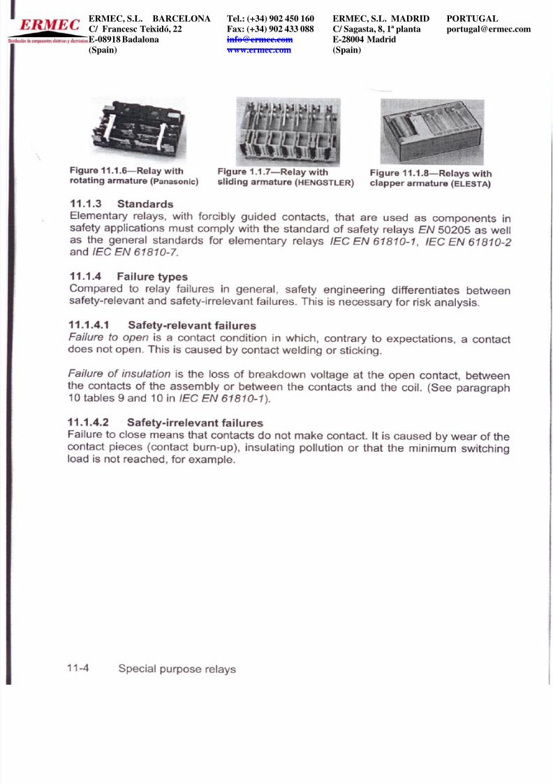
Figures 11.1.6 to 11.1.8 show relay executions with forcibly guided contacts.
Engineers Relay Handbook,
6th
Ed 11-3
~~~l
Figure 11.1.5-Relay in faulty
condition, coil not energized
Figure 11.1.5 demonstrates failure to w ~ll
open after switching off of the energizing
Figure 11.1.4-Relay in working position
voltage at the coil: The middle contact NO-contact) is welded. The contact
springs are connected, to each other by the actuator and the NC- contact cannot
return to its starting position. The NC-contact is used as a control
contact and is therefore unable to close the feedback I O.5·mm·~1 ~.gap
circuit; the failure is detected. The switching
position of the second NO-contact is
undefined since the contacts in the example
do not open in a defined manner.
In the case of a relay without forcibly guided
contacts the NC- and NO-contacts would be
closed at the same time.
Figure 11.1.3 shows the neutral condition of the coil monostable). The relay is in
the free position, the 2 NO-contacts are open and the NC-contact is closed.
Figure 11.1.4 shows the relay with an
energized coil after the end of the switch
on process in a stable condition. The two
NO-contacts are now closed and the NC
contact is open.
ERMEC, S.L. BARCELONAC/ Francesc Teixidó, 22
E-08918 Badalona(Spain)
Tel.: (+34) 902 450 160Fax: (+34) 902 433 088
ERMEC, S.L. MADRIDC/ Sagasta, 8, 1ª planta
E-28004 Madrid(Spain)
7/18/2019 Handbook Safety Relays June-2006
http://slidepdf.com/reader/full/handbook-safety-relays-june-2006 5/13
Figure 11.1.6-Relay with Figure 1.1.7-Relay with Figure 11.1.8-Relays with
rotating armature panasonic sliding armature
HENGSTLER
clapper armature
ELESTA
11.1.3 Standards
Elementary relays, with forcibly guided contacts, that are used as components in
safety applications must comply with the standard of safety relays EN 50205 as well
as the general standards for elementary relays lEC EN 61810-1 lEC EN 61810-2
and lEC EN 61810-7.
11.1.4 Failure types
Compared to relay failures in general, safety engineering differentiates between
safety-relevant and safety-irrelevant failures. This is necessary for risk analysis.
11.1.4.1 Safety-relevant failures
Failure fo open
is a contact condition in which, contrary to expectations, a contact
does not open. This is caused by contact welding or sticking.
Failure of insulation is the loss of breakdown voltage at the open contact, between
the contacts of the assembly or between the contacts and the coil. See paragraph
10 tables 9 and 10 in lEC EN 61810-1 .
11.1.4.2 . Safety-irrelevant failures
Failure to close means that contacts do not make contacto It is caused by wear of the
contact pieces contact burn-up , insulating pollution or that the minimum switching
load is not reached, for example.
ERMEC, S.L. BARCELONAC/ Francesc Teixidó, 22E-08918 Badalona(Spain)
Tel.: (+34) 902 450 160Fax: (+34) 902 433 [email protected]
ERMEC, S.L. MADRIDC/ Sagasta, 8, 1ª plantaE-28004 Madrid(Spain)

7/18/2019 Handbook Safety Relays June-2006
http://slidepdf.com/reader/full/handbook-safety-relays-june-2006 6/13
11.1.5 Application of relays with forcibly guided contacts
Relays with forcibly guided contacts behave
deterministically, Le. clearly foreseeable, also
in case of failure. This means that systems
with single failure safety and self-monitoring
are easy to realize.
Typical applications are:
• Machine tools
• General plant and facility construction
• Process engineering
• Railways and signal engineering
• Medical devices
• Radio and telecontrol
• Fuel technology ..
. . .. Figure 1.1.9-Apphcatlon areas for
• Mlnlng and matenals handling relays with forcibly guided contacts
technology
11.1.6 Remarks on the application of relays with forcibly guided contacts
It must be pointed out that relays of the type described here do not in themselves
represent safety. The task of accomplishing safety is only fulfilled by the appropriate
utilization of the special properties of the forcibly guided contact and a corresponding
safety circuit. Hereby additional requirements must be met which do not directly
relate to the relay.
Such additional requirements include, for example, unintentional breaking and
bridging of power circuits within the control, or externally connected switching
elements. This means that all elements involved in the operation must be considered
and assessed in respect of their behavior in case of failure.
Direct wiring of contacts to protect them from cutoff arcs, for example, must be
avoided. In case of failure, the arrangement protecting the contact can inadmissibly
bridge the contact. The wiring must be assigned to the load to be switched in this
case. Requirements from the standards for appliances and systems of the different
application areas must be met additionally, e.g., lEC 62103 and lEC EN 60204 1
11.1.7 Wiring examples in principie)
The mode of action in the circuit and thereby the
Advantage of the forcible guidance of contacts is demonstrated on the basis of the
following wiring example. For simplicity s sake an example with three relays with a
contact assembly of application type A is used. Solutions with only two relays are
also widely used these days. The simplified example presented here features a 2
channel release circuit. The structure is 2-fold redundant. See Figures 1.1.10-1.1.13.
Engineers Relay Handbook,
6th
Ed 11-5
ERMEC, S.L. BARCELONAC/ Francesc Teixidó, 22E-08918 Badalona(Spain)
Tel.: (+34) 902 450 160Fax: (+34) 902 433 [email protected]
ERMEC, S.L. MADRIDC/ Sagasta, 8, 1ª plantaE-28004 Madrid(Spain)

7/18/2019 Handbook Safety Relays June-2006
http://slidepdf.com/reader/full/handbook-safety-relays-june-2006 7/13
11
Figure 1.1.10- The free position of the relay is shown, both release circuits are interrupted.
The connection points marked 1, 2 and 3 indicate the positions at which the external
switching elements must be looped in. For simplicity s sake these points are bridged here.
2-<:1amE:ln:1eaoe -clroJtI
{~~wltlo¡j·poterf.lar~
2-<:1amekeJeace-drcUrI
{~·Wltlo¡j·polertlal}1
B
2
O
~
t
~
ft
R
e
A
e
B
-¡
Figure 1.1.11-Relay A can respond if the connection point 1 is bridged by external
contacts. At the same time, capacitor C is charged via resistor R (the capacitor serves later
for the release delay of relay A).
11
Figure 1.1.12-When relay A is activated, relays B and C respond via the contacts a-1 and a-
2. Immediately beforehand, the two NC-contacts a-3 and a-4 in the release circuit are
opened. Contacts b-3 and c-3 close after relays B and C are activated. Simultaneously,
contacts b-1 and c-1 are opened and the current supply to relay A is switched off. For this to
happen with a delay, the release is briefly delayed by the discharge of capacitor C. Closing
2-d1amE:l-n:leaoe
drcutl
{~~; wlhOtApolert lal}1
1
R
e
11-6 Special purpose relays
ERMEC, S.L. BARCELONAC/ Francesc Teixidó, 22E-08918 Badalona(Spain)
Tel.: (+34) 902 450 160Fax: (+34) 902 433 [email protected]
ERMEC, S.L. MADRIDC/ Sagasta, 8, 1ª plantaE-28004 Madrid(Spain)
7/18/2019 Handbook Safety Relays June-2006
http://slidepdf.com/reader/full/handbook-safety-relays-june-2006 8/13
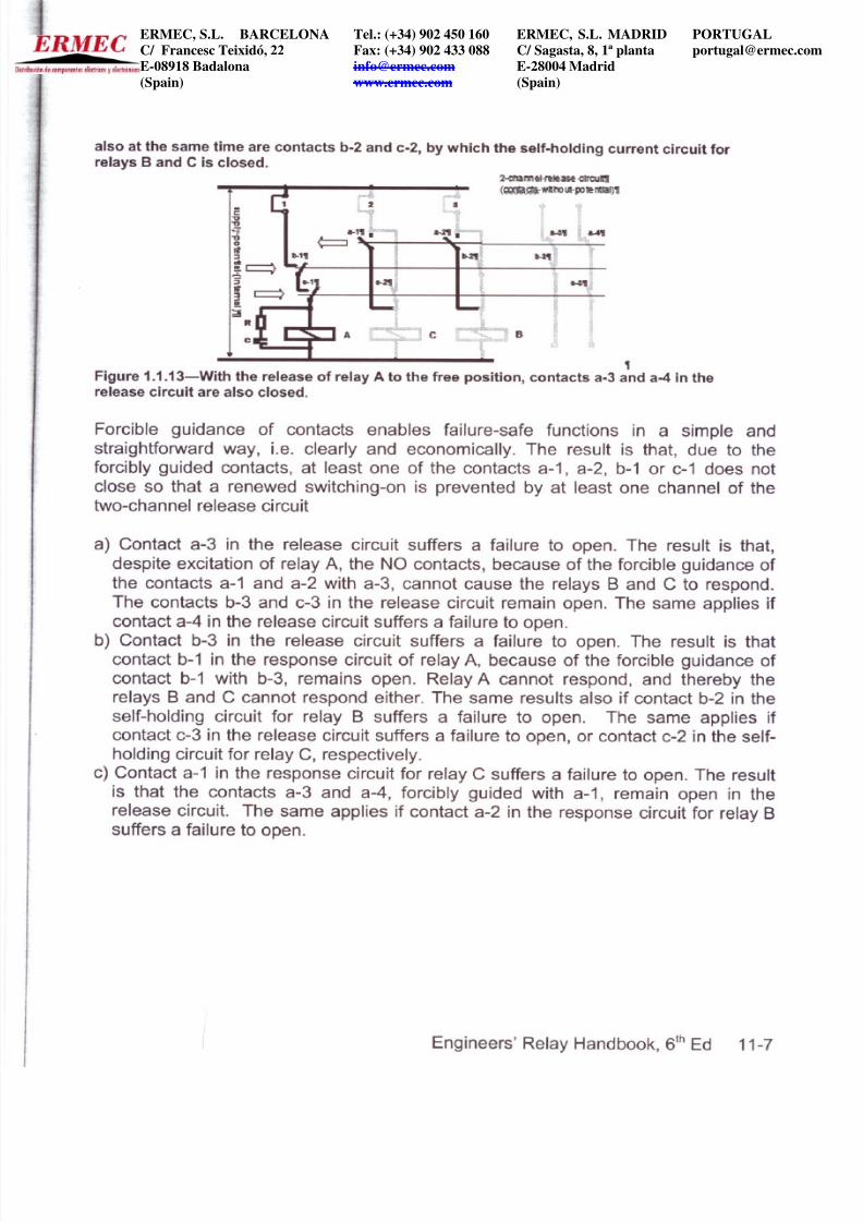
also at the same time are contacts b-2 and c-2, by which the self-holding current circuit for
relays B and
e
is closed.
'[
Figure 1.1.13-With the release of relay A to the free position, contacts a-3 and a-4 in the
release circuit are also closed.
e
2-<: 1amel-re eas.e <:troJ1I
(~~Wln:)I.t·PJ e~'I
?f <I~
í a-3' ~. &-4t
~A
~-~l *-
~I
¡¡; ~
B
Forcible guidance of contacts enables failure-safe functions in a simple and
straightforward way, Le. clearly and economicallyo The result is that, due to the
forcibly guided contacts, at least one of the contacts a-1, a-2, b-1 or c-1 does not
close so that a renewed switching-on is prevented by at least one channel of the
two-channel release circuit
a) Contact a-3 in the release circuit suffers a failure to openo The result is that,
despite excitation of relay A, the NO contacts, because of the forcible guidance of
the contacts a-1 and a-2 with a-3, cannot cause the relays B and C to respondo
The contacts b-3 and c-3 in the release circuit remain openo The same applies if
contact a-4 in the release circuit suffers a failure to openo
b) Contact b-3 in the release circuit suffers a failure to openo The result is that
contact b-1 in the response circuit of relay A, because of the forcible guidance of
contact b-1 with b-3, remains openo Relay A cannot respond, and thereby the
relays B and C cannot respond either. The same results also if contact b-2 in the
self-holding circuit for relay B suffers a failure to openo The same applies if
contact c-3 in the release circuit suffers a failure to open, or contact c-2 in the self
holding circuit for relay C, respectively.
c) Contact a-1 in the response circuit for relay C suffers a failure to openoThe result
is that the contacts a-3 and a-4, forcibly guided with a-1, remain open in the
release circuit. The same applies if contact a-2 in the response circuit for relay B
suffers a failure to openo
Engineers Relay Handbook,
6th
Ed 11-7
ERMEC, S.L. BARCELONAC/ Francesc Teixidó, 22E-08918 Badalona
(Spain)
Tel.: (+34) 902 450 160Fax: (+34) 902 433 [email protected]
www.ermec.com
ERMEC, S.L. MADRIDC/ Sagasta, 8, 1ª plantaE-28004 Madrid
(Spain)
7/18/2019 Handbook Safety Relays June-2006
http://slidepdf.com/reader/full/handbook-safety-relays-june-2006 9/13
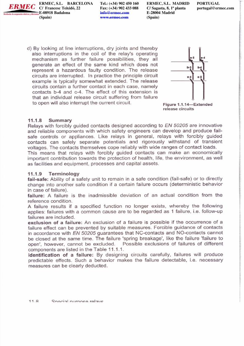
d) By looking at line interruptions, dry joints and thereby
also interruptions in the coil of the relay s operating
mechanism as further failure possibilities, they all
generate an effect of the same kind which does not
represent a hazardous faulty condition. The release
circuits are interrupted. In practice the principie circuit
example is typically somewhat extended. The release
circuits contain a further contact in each case, namely
contacts b-4 and c-4. The effect of this extension is
that an individual release circuit suffering from failure
to open will also interrupt the current circuit.
Figure 1.1.14-Extended
release circuits
11 1 8 Surnrnary
Relays with forcibly guided contacts designed according to EN 5 5 are innovative
and reliable components with which safety engineers can develop and produce fail
safe controls or appliances. Like relays in general, relays with forcibly guided
contacts can safely separate potentials and rigorously withstand of transient
voltages. The contacts themselves cope reliably with wide ranges of contact loads.
This means that relays with forcibly guided contacts can make an economically
important contribution towards the protection of health, life, the environment, as well
as facilities and equipment, processes and capital assets.
11 1 9 Terrninology
fail safe: Ability of a safety unit to remain in a safe condition fail-safe) or to directly
change into another safe condition if a certain failure occurs deterministic behavior
in case of failure).
failure: A failure is the inadmissible deviation of an actual condition from the
reference condition.
A failure results if a specified function no longer exists, whereby the following
applies: failures with a common cause are to be regarded as 1 failure, Le. follow-up
failures are included.
exclusion of a failure: An exclusion of a failure is possible if the occurrence of a
failure effect can be prevented by suitable measures. Forcible guidance of contacts
in accordance with EN 5 5 guarantees that NC-contacts and NO-contacts cannot
be closed at the same time. The failure spring breakage , like the failure failure to
open , however, cannot be excluded. Possible exclusions of failures of different
components are listed in the Table 11.1.1.
identification of a failure: By designing circuits carefully, failures will produce
predictable effects. Such a behavior makes the failure detectable, Le. necessary
measures can be clearly deducted.
ERMEC, S.L. BARCELONAC/ Francesc Teixidó, 22E-08918 Badalona(Spain)
Tel.: (+34) 902 450 160Fax: (+34) 902 433 [email protected]
ERMEC, S.L. MADRIDC/ Sagasta, 8, 1ª plantaE-28004 Madrid(Spain)

7/18/2019 Handbook Safety Relays June-2006
http://slidepdf.com/reader/full/handbook-safety-relays-june-2006 10/13
failure safety single failure safety : Safe engineering is feasible. Engineering free
of failure is utopia. The acceptance of possible events of failure is a prerequisite. As
far as the effect of a failure is concerned, single failure safety is normally demanded.
This means that after an individual failure has occurred, the agreed safe function is
given. Hereby the simultaneous occurrence of two independent failures not is
assumed. Should a risk of this type exist, then monitoring cycles cyclic self
supervision, tests) must take place as frequently as necessary for the above
assumption to be complied with. In its effect, the occurrence of a failure must not
impair the safety, Le. a device s or a system s deterministic behavior. The system
must provide functional safety in a failure-tolerant manner. The cyclic self
supervision serves to reveal the failure.
effect of a failure: The effect generated by the
occurrence of a failure.
These failures affect the function of the relay.
resistor,
Responding is rendered more difficult or made
vañable
impossible in case of a shorted coil; the contact
assembly does not reach the working position. If the
relay is in working position when the failure occurs,
this position is maintained or the contact mechanism changes to the free position.
The appropriate circuit technique makes these failures detectable. The release
circuits are either interrupted or not closed in the first place. The failures assumed
here can also occur when the components are wired together. An interruption can be
caused by a dry joint, just like a short circuit by a failure in a capacitor. Certain
failures can be excluded. In this case one refers to the exclusion of a failure in
11.1.11.
failure modes and effects analysis FMEA :
The study of consequences of failure
events for the purpose of assessing risks.
NOTE-In safety engineering, faHures that may impair safety and cannot be detected are not
allowed to impair the safety. This applies also to the accumulation of such faHures.
AII the assumed failures mentioned lead to a condition which does not impair the
safety-technical function. Hereby, however, relays must not be seen as isolated
components. Instead, the wiring technique and the way in which it is implemented
must be included, so that failures are detected with each switching cycle See test
at the latest.
Let us look at the winding of a relay operating
mechanism. In principie the same possibilities for
failures are given as in the case of an ohmic resistor.
A shorted coil changes the value of the resistor, it
decreases at will, a short circuit can even occur.
Resistance rises to infinity if the conductor is
interrupted.
relay
o l
Engineers Relay Handbook, 6th Ed 11-9
ERMEC, S.L. BARCELONAC/ Francesc Teixidó, 22E-08918 Badalona
(Spain)
Tel.: (+34) 902 450 160Fax: (+34) 902 433 [email protected]
www.ermec.com
ERMEC, S.L. MADRIDC/ Sagasta, 8, 1ª plantaE-28004 Madrid
(Spain)

7/18/2019 Handbook Safety Relays June-2006
http://slidepdf.com/reader/full/handbook-safety-relays-june-2006 11/13
faulty condition: Condition of one item with failures at the time of inspection. The
condition is subject to a failure of a system or device without impairing the safety.
release circuit: Output contact circuit of a device with safety-related function, whose
closing takes place only after it has been tested and confirmed that the function of
the device is as intended.
failure of insulation: Failure of insulation can be excluded, provided that the rules
of insulation coordination are used as the basis for dimensioning. The standards for
the corresponding devices and systems that describe the requirements applicable to
the deployment in question must be observed, e.g., lEC 62103/EN 50178 and
lEC 60204-1. For the relays per se, lEC EN 61801-1 applies in this context.
failure to open: Contrary to expectation, a closed contact doesn t open. This is
possible with both NC- and NO contacts.
redundancy: In engineering, it is the extra effort that is not directly required for the
function of a system, the parallel connection of two systems so that the function is
maintained even if one system fails. In standardization, it is the application of more
than one device or system or part of a device or system to ensure that another one is
available to perform this function in case of a malfunction lEC/EN 60204-1 . In
automation a two-fold redundancy (two-channel feature) is very common. If the two
systems yield different results, an undesirable condition is the result.
homogenous redundancy: Redundancy that employs identical means. In everyday
life, wearing two belts or two suspenders simultaneously would be a homogenous
redundant system. Your pants would stay up even if one of the two holding devices
failed.
diverse redundancy: Redundancy in which the means are non-uniformo In everyday
life, the wearing a belt and a suspender simultaneously would be a diverse
redundant system to hold up your pants even if one of the two holding devices failed.
Belt and suspender are unequal means. NC- and NO-contacts are diverse contacts.
The series connection of NC- and NO-contacts is a diverse-redundant contact chain.
By means of the order of contact actuation, the contacts are also assigned a certain
strain (simultaneous closing or opening must be avoided). In the above-discussed
connection example this is given for the contacts in the release circuit. The order for
closing the release circuit is as follows:
- NC-contact opens
NO-contact closes- NC-contact closes.
In this order of actuation, the NC-contact is responsible for the switch-on
process. If the power circuit is interrupted, by opening the NO-contact, the
latter becomes responsible for the switch-off process.
test: Process of testing whether or not a certain function exists when the test is
performed. One also refers to cyclic testing, if this process is repeated, prior to each
activation.
11-10
Special purpose relays
ERMEC, S.L. BARCELONAC/ Francesc Teixidó, 22E-08918 Badalona(Spain)
Tel.: (+34) 902 450 160Fax: (+34) 902 433 [email protected]
ERMEC, S.L. MADRIDC/ Sagasta, 8, 1ª plantaE-28004 Madrid(Spain)

7/18/2019 Handbook Safety Relays June-2006
http://slidepdf.com/reader/full/handbook-safety-relays-june-2006 12/13
direct opening action: To ensure a contact separation as a direct result of a
defined movement of the operating part of the switch via non-spring-Ioaded parts,
e.g., not dependent on a spring lEC EN 60947-5-1 .
11 1 10 Standards
EN 50205: Relays with forcibly guided mechanically linked) contacts
lEC EN 60204 1: Safety of machinery - Electrical equipment of machines-Part 1:
General requirements
lEC EN 60947 5 1: Low-voltage switchgear and control gear-Part 5-1: Control circuit
devices
lEC EN 61810 1: Electromechanical Elementary Relays-Part 1: General and safety
requirements
lEC EN 61810 2: Electromechanical Elementary Relays-Part 2: Reliability
lEC EN 61810 7: Electromechanical Elementary Relays-Part 7: Test and
measurement procedures
lEC 62103/EN 50178: Electronic Equipment for use in power installations
ISO EN 13849 2: Safety of machinery - Safety-related parts of control systems-Part
2: Validation
11 1 11 Failure exclusion table
Apart from relays, other components are used in power circuits of relevance to
safety. Failure exclusions are admissible for these components subject to certain
conditions. The basis for this, are for example physical circumstances capacitors do
not display a strong increase in capacity in case of failure, Le. the fault increase of
capacity can be excluded) or also design circumstances cement-coated wire
resistors or coiled metal film resistors may suffer from an interruption as a failure, but
the failure short-circuit can be excluded).
ERMEC, S.L. BARCELONAC/ Francesc Teixidó, 22E-08918 Badalona(Spain)
Tel.: (+34) 902 450 160Fax: (+34) 902 433 [email protected]
ERMEC, S.L. MADRIDC/ Sagasta, 8, 1ª plantaE-28004 Madrid(Spain)

7/18/2019 Handbook Safety Relays June-2006
http://slidepdf.com/reader/full/handbook-safety-relays-june-2006 13/13
ISO 13849 2 among others also deals in its appendices with safety principies lists
of failures and exclusions of failures. Table 11.1.1 provides an overview.
Table 11.1.1 Failure exclusion table
Assumed failure Failure exclusion
Com.e.0nent
Printed circuit
board
Electrical
contact
Electrolyte
capacitor
Wire resistor
Semiconductor
diode
Short circuit between
wiring paths
Interruption of wiring
paths
Failure to close
Failure to open
Interruption
Leakage current
Short circuit
Capacity increase
Capacity decrease
Interruption
Short circuit
Resistance increase
Resistance decrease
Interru ption
Leakage current
Short circuit
Yes particular
assumptions
No
No
No
Yes
No
Poss. within limits
Yes
Poss. within limits
No
No
No
Remark
Air gaps and creepage
distances must correspond at
least to the insulation
coordination see applicable
basic standard such as e.g.
lEC 62103
It must be prevented in principie
that conductive parts coming
loose can bridge the contact.
Single Iayer wire coil cemented
glazed or embedded
The correspondingly same
applied to all semiconductor
components
ERMEC, S.L. BARCELONAC/ Francesc Teixidó, 22E-08918 Badalona(Spain)
Tel.: (+34) 902 450 160Fax: (+34) 902 433 [email protected]
ERMEC, S.L. MADRIDC/ Sagasta, 8, 1ª plantaE-28004 Madrid(Spain)
![[ 3000 Series Time Delay Relays and Measuring Relays ... · [ 3000 Series Time Delay Relays and Measuring Relays ] ... Measuring Relays ] • Time Delay Relays ... Dear Reader, Dear](https://static.fdocuments.us/doc/165x107/5b85683b7f8b9aec488e43dd/-3000-series-time-delay-relays-and-measuring-relays-3000-series-time.jpg)