Handbook - RSSB Iss 3.pdf · Signals, handsignals, indicators and signs Handbook RS/521 Issue 3...
64
Signals, handsignals, indicators and signs Handbook RS/521 Issue 3 December 2015 Uncontrolled When Printed Document comes into force and supersedes RS521 Iss 2 on 05/12/2015 Superseded by RS521 Iss 4 with effect from 03/12/2016
Transcript of Handbook - RSSB Iss 3.pdf · Signals, handsignals, indicators and signs Handbook RS/521 Issue 3...

Signals,
handsignals,
indicators and signs
HandbookRS/521 Issue 3
December 2015
Uncontrolled When Printed Document comes into force and supersedes RS521 Iss 2 on 05/12/2015 Superseded by RS521 Iss 4 with effect from 03/12/2016

Signals, handsignals,
indicators and signs
HandbookRS/521 Issue 3 (December 2015)
© Copyright 2015Rail Safety and Standards Board Limited
Published by:
RSSB
The authoritative version of this document is available at
www.rssb.co.uk/rgsonline
Contents approved by Traffic Operation and Management
Standards Committee.
Enquiries on this document can be forwarded to:
Uncontrolled When Printed Document comes into force and supersedes RS521 Iss 2 on 05/12/2015 Superseded by RS521 Iss 4 with effect from 03/12/2016
1
You will need this handbook if you
need to understand the meaning of
signals, handsignals, indicators and
signs.
Uncontrolled When Printed Document comes into force and supersedes RS521 Iss 2 on 05/12/2015 Superseded by RS521 Iss 4 with effect from 03/12/2016

Contents
2
Definitions and identification of signals
1.1 Definitions
1.2 Signal types - identification
Colour light signals
2.1 Three-aspect signalling - normal sequence
2.2 Four-aspect signalling - normal sequence
2.3 Junction indicators
2.4 Route indicators
2.5 Flashing yellow aspects
2.6 Position-light signals
2.7 Colour light signals not in use
Semaphore signals
3.1 Distant signals
3.2 Stop signals
3.3 Route indications
3.4 Semaphore subsidiary signals
3.5 Semaphore shunting signals that display a red aspect
3.6 Semaphore shunting signals that display a yellow aspect
3.7 Route indications by shunting signals
3.8 Semaphore signals not in use
ERTMS boards
4.1 Block markers
4.2 ERTMS lines where lineside signals are provided
4.3 Cab signalling boards
4.4 Shunt entry boards
1
2
3
4
Uncontrolled When Printed Document comes into force and supersedes RS521 Iss 2 on 05/12/2015 Superseded by RS521 Iss 4 with effect from 03/12/2016

3
Contents
Other signals and indicators
5.1 Limit of shunt signals or indicators
5.2 Stop boards
5.3 Possession limit boards (PLB)
5.4 Work-site marker boards
5.5 Signal passed at danger (SPAD) indicator
5.6 Points indicators
5.7 Banner repeating and co-acting signals
5.8 ‘Off’ indicators
5.9 ‘Close-doors’ indicator
5.10 ‘Right-away’ indicators
5.11 Rear clear marker
5.12 Mid-platform train berth marker
5.13 Whistle boards
5.14 Preliminary route indicators
5.15 Automatic warning system (AWS) cancelling indicators
5.16 AWS gap indicators
Level crossing signs and indicators
6.1 Level crossing signs
6.2 Level crossing indicators
6
5
Uncontrolled When Printed Document comes into force and supersedes RS521 Iss 2 on 05/12/2015 Superseded by RS521 Iss 4 with effect from 03/12/2016
Contents
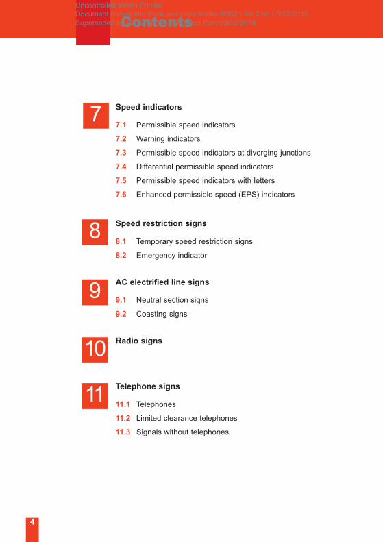
Speed indicators
7.1 Permissible speed indicators
7.2 Warning indicators
7.3 Permissible speed indicators at diverging junctions
7.4 Differential permissible speed indicators
7.5 Permissible speed indicators with letters
7.6 Enhanced permissible speed (EPS) indicators
Speed restriction signs
8.1 Temporary speed restriction signs
8.2 Emergency indicator
AC electrified line signs
9.1 Neutral section signs
9.2 Coasting signs
Radio signs
Telephone signs
11.1 Telephones
11.2 Limited clearance telephones
11.3 Signals without telephones
8
9
10
11
4
7
Uncontrolled When Printed Document comes into force and supersedes RS521 Iss 2 on 05/12/2015 Superseded by RS521 Iss 4 with effect from 03/12/2016
5
Other lineside signs
12.1 Low adhesion hazard signs
12.2 Sandite markers
12.3 Signal reminder signs
12.4 Countdown markers
12.5 Coasting boards
12.6 Car stop markers
12.7 Mile posts
12.8 Gradient signs
12.9 Spring catch points sign
12.10 Bridge identity plates
12.11 Safety signs
Lineside handsignals
12
13
ContentsUncontrolled When Printed Document comes into force and supersedes RS521 Iss 2 on 05/12/2015 Superseded by RS521 Iss 4 with effect from 03/12/2016
6
1 Definitions and identificationof signals
1.1 Definitions
Stop signal
A stop signal is a signal that can show a stop aspect or indication.
It also includes:
• position-light signals
• shunting signals
• limit of shunt signals or indicators
• stop boards
• possession limit boards
• work-site marker boards.
Distant signal
A distant signal is a signal which cannot show a stop aspect or
indication.
Some colour light distant signals are identified by a white triangle
or the letters ‘R’ or ‘RR’ on the signal identification plate.
Automatic signal
A signal operated by the passage of trains. The signaller or a
person operating a signal post replacement switch can place some
automatic signals to danger.
Controlled signal
A signal operated by the signaller, some of which may be set by
the signaller to work automatically.
Semi-automatic signal
A signal normally operated by the passage of trains, but can also
be controlled from a signal box or a ground frame.
Intermediate block home signal
A stop signal that controls the exit from an intermediate block
section, and the entrance to an absolute block section or another
intermediate block section.
Uncontrolled When Printed Document comes into force and supersedes RS521 Iss 2 on 05/12/2015 Superseded by RS521 Iss 4 with effect from 03/12/2016

1 Definitions and identificationof signals
1.2 Signal types - identification
The meanings of signal identification plates are as follows:
Controlled signal
Automatic signal
Semi-automatic signal
Intermediate block signal
Distant signals
Outer distant signal
Banner repeating signal
Co-acting signalC
3 state bannerrepeating signal
Controlled signalsignalsDistant
Automatic signal
Banner repeating
Outer distant signal
Banner repeating
Outer distant signal
signalSemi-automatic
signal
repeating signal3 state banner
signal
repeating signal3 state banner
signalIntermediate block
Co-acting signalC Co-acting signal
7
Uncontrolled When Printed Document comes into force and supersedes RS521 Iss 2 on 05/12/2015 Superseded by RS521 Iss 4 with effect from 03/12/2016
8
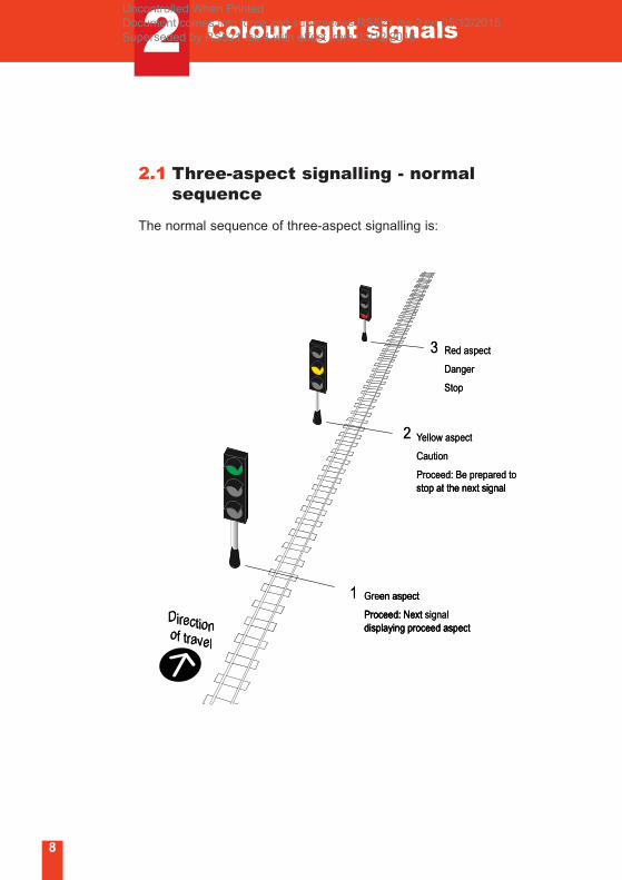
2.1 Three-aspect signalling - normal sequence
The normal sequence of three-aspect signalling is:
Directionof travel
Green aspect
Proceed: Next signaldisplaying proceed aspect
Yellow aspect
Caution
Proceed: Be prepared tostop at the next signal
Red aspect
Danger
Stop
2
3
1
3
2
Stop
Danger
aspectRed
stop at the next signalBe prepared toProceed:
Caution
ellow aspectYYe
of travel
Directiononofdisplaying proceed aspectProceed: Next
en aspectGre1
stop at the next signal
displaying proceed aspectsignalProceed: Next
en aspect
2 Colour light signalsUncontrolled When Printed Document comes into force and supersedes RS521 Iss 2 on 05/12/2015 Superseded by RS521 Iss 4 with effect from 03/12/2016
2 Colour light signals
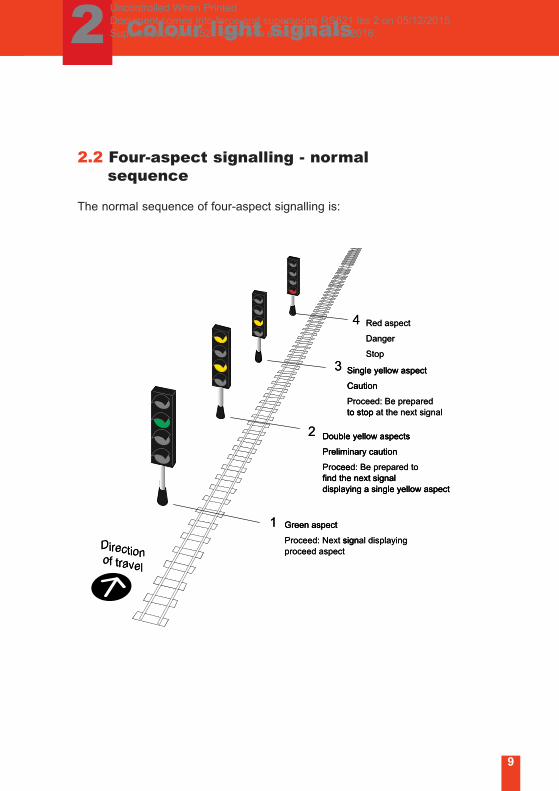
2.2 Four-aspect signalling - normalsequence
The normal sequence of four-aspect signalling is:
Directionof travel
Red aspect
Danger
Stop
Single yellow aspect
Caution
Proceed: Be preparedto stop at the next signal
Double yellow aspects
Preliminary caution
Proceed: Be prepared tofind the next signaldisplaying a single yellow aspect
Green aspect
Proceed: Next signal displayingproceed aspect
1
2
3
4
Caution
Single yellow aspect3Stop
Danger
Red aspect
Caution
Single yellow aspect
4
Green aspect
displaying a single yellow aspectfind the next signal
ceePro
Preliminary caution
Double yellow aspects
to stop
2
1
displaying a single yellow aspectfind the next signal
repared tod: Be pcee
Preliminary caution
Double yellow aspects
at the next signalto stop Be preparedeed:cPro
of travel
Directiononofproceed aspect
signProceed: Next
Green aspect
al displayingsign
9
Uncontrolled When Printed Document comes into force and supersedes RS521 Iss 2 on 05/12/2015 Superseded by RS521 Iss 4 with effect from 03/12/2016
Colour light signals2
10
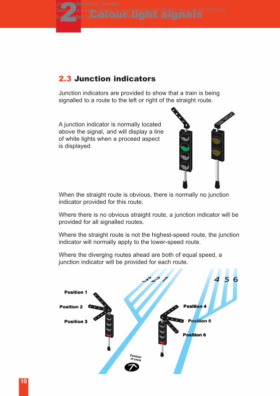
2.3 Junction indicators
Junction indicators are provided to show that a train is being
signalled to a route to the left or right of the straight route.
A junction indicator is normally located
above the signal, and will display a line
of white lights when a proceed aspect
is displayed.
When the straight route is obvious, there is normally no junction
indicator provided for this route.
Where there is no obvious straight route, a junction indicator will be
provided for all signalled routes.
Where the straight route is not the highest-speed route, the junction
indicator will normally apply to the lower-speed route.
Where the diverging routes ahead are both of equal speed, a
junction indicator will be provided for each route.
Directionof travel
Position 4
Position 5
Position 6
Position 1
Position 2
Position 3n 3Positio
Position 2
Position 1
n 3
Position 4
Position 5
Position 4
of traDirecof avel
ctionon
Position 6Position 6
Uncontrolled When Printed Document comes into force and supersedes RS521 Iss 2 on 05/12/2015 Superseded by RS521 Iss 4 with effect from 03/12/2016
Colour light signals2
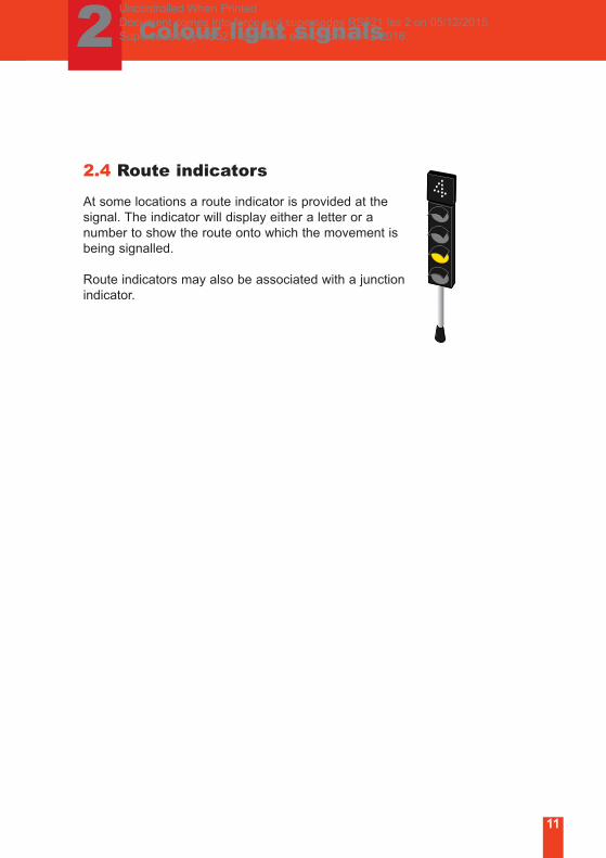
2.4 Route indicators
At some locations a route indicator is provided at the
signal. The indicator will display either a letter or a
number to show the route onto which the movement is
being signalled.
Route indicators may also be associated with a junction
indicator.
11
Uncontrolled When Printed Document comes into force and supersedes RS521 Iss 2 on 05/12/2015 Superseded by RS521 Iss 4 with effect from 03/12/2016

2 Colour light signals
12
2.5 Flashing yellow aspects
A flashing yellow aspect means facing points at a junction ahead
are set for a diverging route and the speed of the train must be
reduced.
The normal sequence of three-aspect flashing yellow signalling is:
Three-aspect flashing yellow signalling
When a single steady yellow aspect is displayed together with a
junction indicator at signal 4, the driver must obey the caution
aspect and be prepared to stop at signal 5. This applies even
though a flashing aspect may have been displayed at signal 3.
1
2
Directionof travel
Green
Single flashing yellow
Single steady yellowwith junction indicator
Red
Green
3
4
5 Red 5
2
wS
Single flashing yellow
Green
4
3
with junction indicatorSingle steady yellowg y y
ith j ti i di t
Single flashing yellow
of travelnof
Direction
1 Green
Uncontrolled When Printed Document comes into force and supersedes RS521 Iss 2 on 05/12/2015 Superseded by RS521 Iss 4 with effect from 03/12/2016
2 Colour light signals
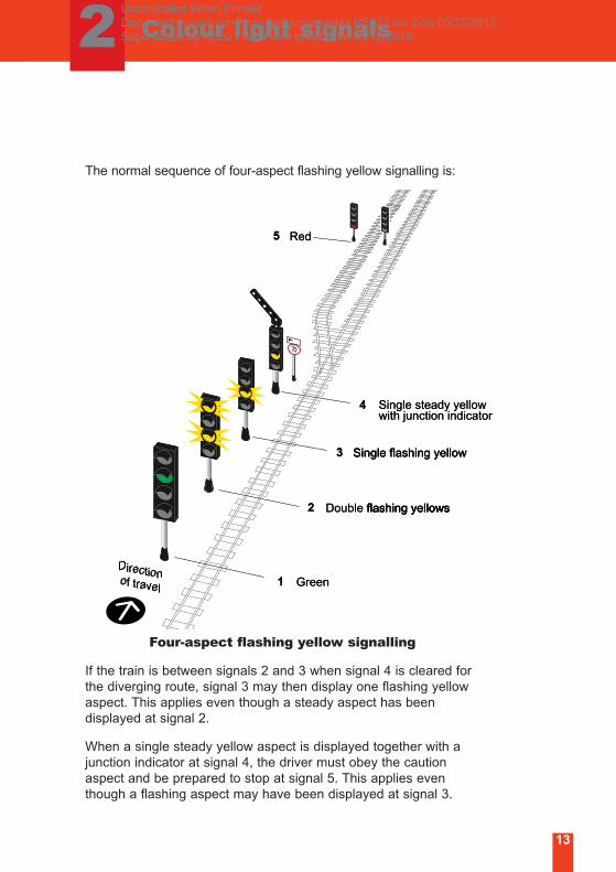
The normal sequence of four-aspect flashing yellow signalling is:
Four-aspect flashing yellow signalling
If the train is between signals 2 and 3 when signal 4 is cleared for
the diverging route, signal 3 may then display one flashing yellow
aspect. This applies even though a steady aspect has been
displayed at signal 2.
When a single steady yellow aspect is displayed together with a
junction indicator at signal 4, the driver must obey the caution
aspect and be prepared to stop at signal 5. This applies even
though a flashing aspect may have been displayed at signal 3.
Directionof travel
Double flashing yellows
Single flashing yellow
Single steady yellow with junction indicator
Red
Green 1
2
3
4
55 Red
4
3
2
wS
Single flashing yellow
flashing yellowsDouble
with junction indicatorSingle steady yellow g y y
ith j ti i di t
Single flashing yellow
flashing yellows
of travel
Directiononof 1 Green
flashing yellows
13
Uncontrolled When Printed Document comes into force and supersedes RS521 Iss 2 on 05/12/2015 Superseded by RS521 Iss 4 with effect from 03/12/2016
Colour light signals2
14
Flashing yellow signalling in ERTMS areas
For trains on which ERTMS is operating the ability of approaching
signals to display flashing aspects will be disabled. Only standard
aspect sequences will be displayed to these trains. Route or
junction indicators will continue to operate.
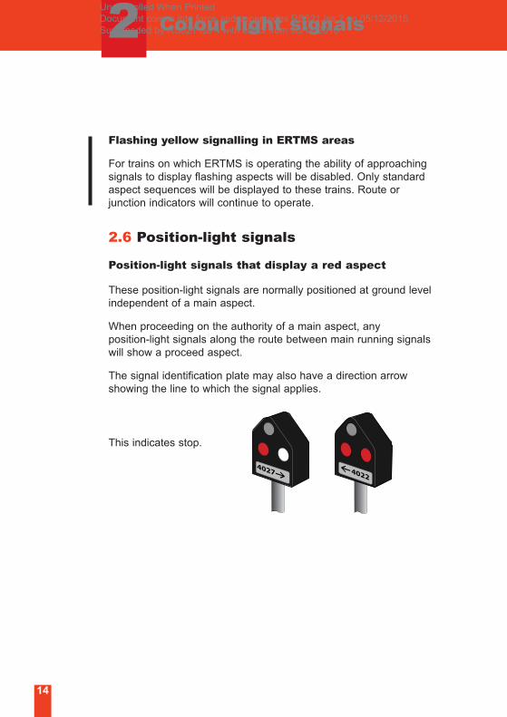
2.6 Position-light signals
Position-light signals that display a red aspect
These position-light signals are normally positioned at ground level
independent of a main aspect.
When proceeding on the authority of a main aspect, any
position-light signals along the route between main running signals
will show a proceed aspect.
The signal identification plate may also have a direction arrow
showing the line to which the signal applies.
This indicates stop.
Uncontrolled When Printed Document comes into force and supersedes RS521 Iss 2 on 05/12/2015 Superseded by RS521 Iss 4 with effect from 03/12/2016
Colour light signals2
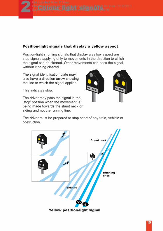
Shunt neck
Sidings
Runninglines
Yellow position-light signal
15
Position-light signals that display a yellow aspect
Position-light shunting signals that display a yellow aspect are
stop signals applying only to movements in the direction to which
the signal can be cleared. Other movements can pass the signal
without it being cleared.
The signal identification plate may
also have a direction arrow showing
the line to which the signal applies.
This indicates stop.
The driver may pass the signal in the
‘stop’ position when the movement is
being made towards the shunt neck or
siding and not the running line.
The driver must be prepared to stop short of any train, vehicle or
obstruction.
Uncontrolled When Printed Document comes into force and supersedes RS521 Iss 2 on 05/12/2015 Superseded by RS521 Iss 4 with effect from 03/12/2016
2 Colour light signals
16
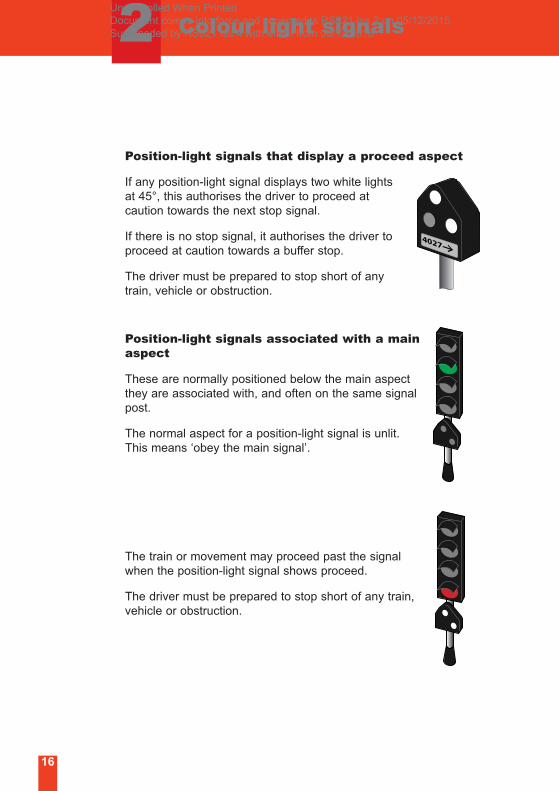
Position-light signals that display a proceed aspect
If any position-light signal displays two white lights
at 45°, this authorises the driver to proceed at
caution towards the next stop signal.
If there is no stop signal, it authorises the driver to
proceed at caution towards a buffer stop.
The driver must be prepared to stop short of any
train, vehicle or obstruction.
Position-light signals associated with a mainaspect
These are normally positioned below the main aspect
they are associated with, and often on the same signal
post.
The normal aspect for a position-light signal is unlit.
This means ‘obey the main signal’.
The train or movement may proceed past the signal
when the position-light signal shows proceed.
The driver must be prepared to stop short of any train,
vehicle or obstruction.
Uncontrolled When Printed Document comes into force and supersedes RS521 Iss 2 on 05/12/2015 Superseded by RS521 Iss 4 with effect from 03/12/2016
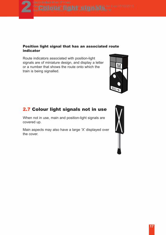
Position light signal that has an associated routeindicator
Route indicators associated with position-light
signals are of miniature design, and display a letter
or a number that shows the route onto which the
train is being signalled.
2.7 Colour light signals not in use
When not in use, main and position-light signals are
covered up.
Main aspects may also have a large ‘X’ displayed over
the cover.
17
Colour light signals2 Uncontrolled When Printed Document comes into force and supersedes RS521 Iss 2 on 05/12/2015 Superseded by RS521 Iss 4 with effect from 03/12/2016
18
3 Semaphore signals
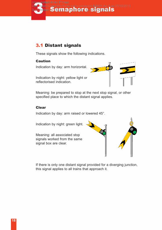
3.1 Distant signals
These signals show the following indications.
Caution
Indication by day: arm horizontal.
Indication by night: yellow light or
reflectorised indication.
Meaning: be prepared to stop at the next stop signal, or other
specified place to which the distant signal applies.
Clear
Indication by day: arm raised or lowered 45°.
Indication by night: green light.
Meaning: all associated stop
signals worked from the same
signal box are clear.
If there is only one distant signal provided for a diverging junction,
this signal applies to all trains that approach it.
Uncontrolled When Printed Document comes into force and supersedes RS521 Iss 2 on 05/12/2015 Superseded by RS521 Iss 4 with effect from 03/12/2016
3 Semaphore signals
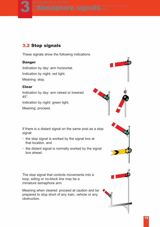
3.2 Stop signals
These signals show the following indications.
Danger
Indication by day: arm horizontal.
Indication by night: red light.
Meaning: stop.
Clear
Indication by day: arm raised or lowered
45°.
Indication by night: green light.
Meaning: proceed.
If there is a distant signal on the same post as a stop
signal:
• the stop signal is worked by the signal box at
that location, and
• the distant signal is normally worked by the signal
box ahead.
The stop signal that controls movements into a
loop, siding or no-block line may be a
miniature semaphore arm.
Meaning when cleared: proceed at caution and be
prepared to stop short of any train, vehicle or any
obstruction.
19
Uncontrolled When Printed Document comes into force and supersedes RS521 Iss 2 on 05/12/2015 Superseded by RS521 Iss 4 with effect from 03/12/2016
3 Semaphore signals
20
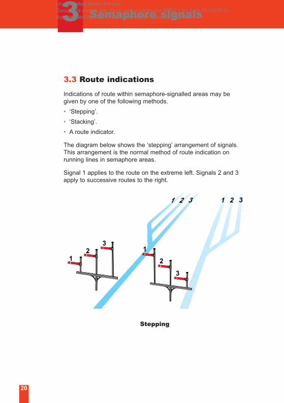
3.3 Route indications
Indications of route within semaphore-signalled areas may be
given by one of the following methods.
• ‘Stepping’.
• ‘Stacking’.
• A route indicator.
The diagram below shows the ‘stepping’ arrangement of signals.
This arrangement is the normal method of route indication on
running lines in semaphore areas.
Signal 1 applies to the route on the extreme left. Signals 2 and 3
apply to successive routes to the right.
Stepping
12
31
2
3
Uncontrolled When Printed Document comes into force and supersedes RS521 Iss 2 on 05/12/2015 Superseded by RS521 Iss 4 with effect from 03/12/2016
3 Semaphore signals
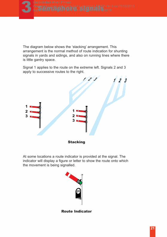
The diagram below shows the ‘stacking’ arrangement. This
arrangement is the normal method of route indication for shunting
signals in yards and sidings, and also on running lines where there
is little gantry space.
Signal 1 applies to the route on the extreme left. Signals 2 and 3
apply to successive routes to the right.
Stacking
At some locations a route indicator is provided at the signal. The
indicator will display a figure or letter to show the route onto which
the movement is being signalled.
Route Indicator
1
32 1
32
21
Uncontrolled When Printed Document comes into force and supersedes RS521 Iss 2 on 05/12/2015 Superseded by RS521 Iss 4 with effect from 03/12/2016
Semaphore signals3
22
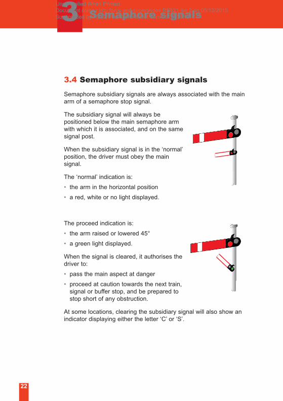
3.4 Semaphore subsidiary signals
Semaphore subsidiary signals are always associated with the main
arm of a semaphore stop signal.
The subsidiary signal will always be
positioned below the main semaphore arm
with which it is associated, and on the same
signal post.
When the subsidiary signal is in the ‘normal’
position, the driver must obey the main
signal.
The ‘normal’ indication is:
• the arm in the horizontal position
• a red, white or no light displayed.
The proceed indication is:
• the arm raised or lowered 45°
• a green light displayed.
When the signal is cleared, it authorises the
driver to:
• pass the main aspect at danger
• proceed at caution towards the next train,
signal or buffer stop, and be prepared to
stop short of any obstruction.
At some locations, clearing the subsidiary signal will also show an
indicator displaying either the letter ‘C’ or ‘S’.
Uncontrolled When Printed Document comes into force and supersedes RS521 Iss 2 on 05/12/2015 Superseded by RS521 Iss 4 with effect from 03/12/2016
3 Semaphore signals
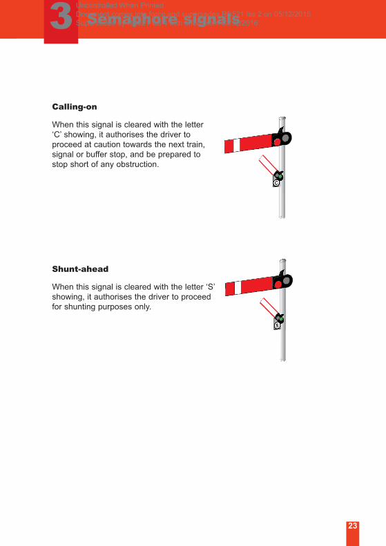
Calling-on
When this signal is cleared with the letter
‘C’ showing, it authorises the driver to
proceed at caution towards the next train,
signal or buffer stop, and be prepared to
stop short of any obstruction.
Shunt-ahead
When this signal is cleared with the letter ‘S’
showing, it authorises the driver to proceed
for shunting purposes only.
23
Uncontrolled When Printed Document comes into force and supersedes RS521 Iss 2 on 05/12/2015 Superseded by RS521 Iss 4 with effect from 03/12/2016
3 Semaphore signals
24
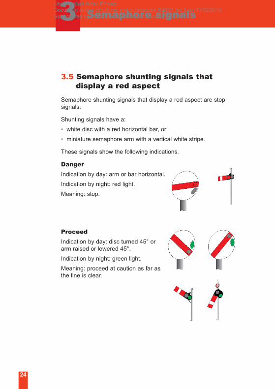
3.5 Semaphore shunting signals that display a red aspect
Semaphore shunting signals that display a red aspect are stop
signals.
Shunting signals have a:
• white disc with a red horizontal bar, or
• miniature semaphore arm with a vertical white stripe.
These signals show the following indications.
Danger
Indication by day: arm or bar horizontal.
Indication by night: red light.
Meaning: stop.
Proceed
Indication by day: disc turned 45° or
arm raised or lowered 45°.
Indication by night: green light.
Meaning: proceed at caution as far as
the line is clear.
Uncontrolled When Printed Document comes into force and supersedes RS521 Iss 2 on 05/12/2015 Superseded by RS521 Iss 4 with effect from 03/12/2016
3 Semaphore signals
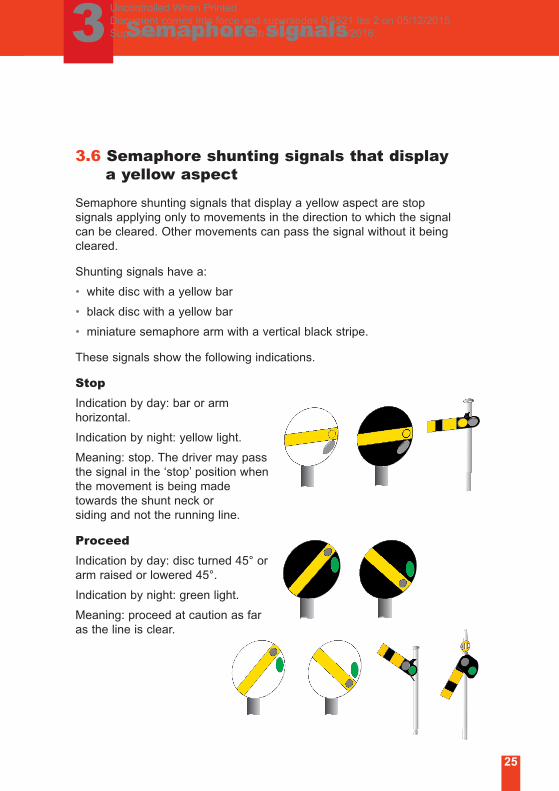
3.6 Semaphore shunting signals that display a yellow aspect
Semaphore shunting signals that display a yellow aspect are stop
signals applying only to movements in the direction to which the signal
can be cleared. Other movements can pass the signal without it being
cleared.
Shunting signals have a:
• white disc with a yellow bar
• black disc with a yellow bar
• miniature semaphore arm with a vertical black stripe.
These signals show the following indications.
Stop
Indication by day: bar or arm
horizontal.
Indication by night: yellow light.
Meaning: stop. The driver may pass
the signal in the ‘stop’ position when
the movement is being made
towards the shunt neck or
siding and not the running line.
Proceed
Indication by day: disc turned 45° or
arm raised or lowered 45°.
Indication by night: green light.
Meaning: proceed at caution as far
as the line is clear.
25
Uncontrolled When Printed Document comes into force and supersedes RS521 Iss 2 on 05/12/2015 Superseded by RS521 Iss 4 with effect from 03/12/2016
3 Semaphore signals
26
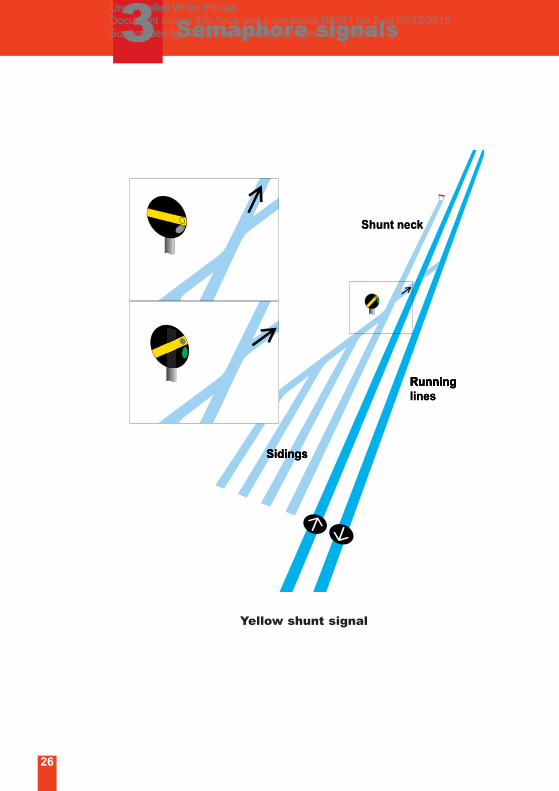
Shunt neck
Sidings
Runninglines
Shunt neck
RunningRunning
SidingsSidingSidings
linesRunning
Yellow shunt signal
Uncontrolled When Printed Document comes into force and supersedes RS521 Iss 2 on 05/12/2015 Superseded by RS521 Iss 4 with effect from 03/12/2016
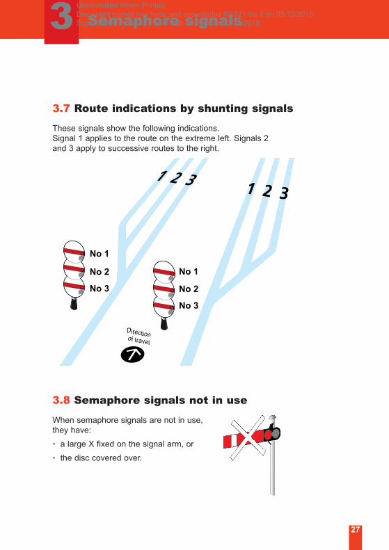
3.7 Route indications by shunting signals
These signals show the following indications.
Signal 1 applies to the route on the extreme left. Signals 2
and 3 apply to successive routes to the right.
3.8 Semaphore signals not in use
When semaphore signals are not in use,
they have:
• a large X fixed on the signal arm, or
• the disc covered over.
No 1
No 2
No 3
Directionof travel
No 1
No 2
No 3
27
3 Semaphore signalsUncontrolled When Printed Document comes into force and supersedes RS521 Iss 2 on 05/12/2015 Superseded by RS521 Iss 4 with effect from 03/12/2016
4 ERTMS boards
28
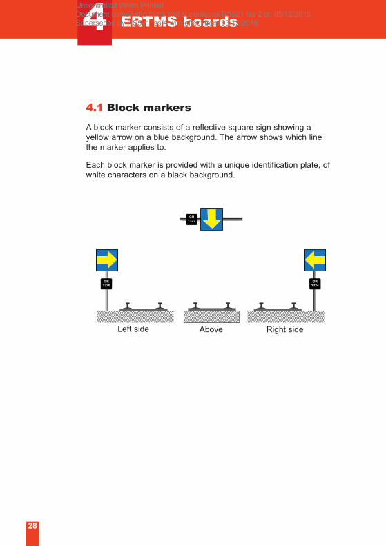
4.1 Block markers
A block marker consists of a reflective square sign showing a
yellow arrow on a blue background. The arrow shows which line
the marker applies to.
Each block marker is provided with a unique identification plate, of
white characters on a black background.
GR1320
GR1324
GR1322
Left side Right sideAbove
Uncontrolled When Printed Document comes into force and supersedes RS521 Iss 2 on 05/12/2015 Superseded by RS521 Iss 4 with effect from 03/12/2016
4 ERTMS boards
29
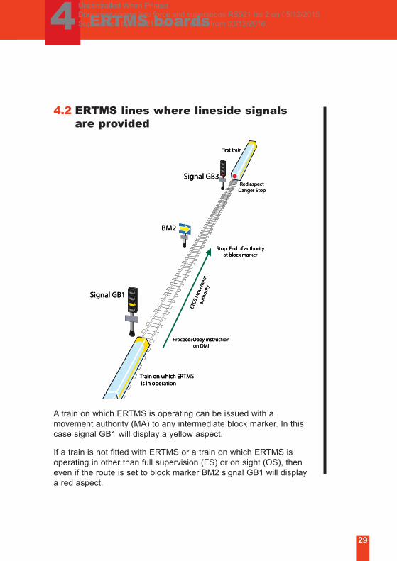
4.2 ERTMS lines where lineside signals are provided
A train on which ERTMS is operating can be issued with a
movement authority (MA) to any intermediate block marker. In this
case signal GB1 will display a yellow aspect.
If a train is not fitted with ERTMS or a train on which ERTMS is
operating in other than full supervision (FS) or on sight (OS), then
even if the route is set to block marker BM2 signal GB1 will display
a red aspect.
Signal GB1
Signal GB3
BM2
ETCS
Mov
emen
tau
thor
ity
Proceed: Obey instructionon DMI
Stop: End of authorityat block marker
Red aspectDanger Stop
First train
Train on which ERTMS is in operation
nal GB3gSi
irst tF ainrirst t
BM2
g
t block maaop: End of authotS
optSDanger tced aspeR
kerrt block maytirop: End of autho
nal GB1gSi
tionceed: Obey instrucorP
yttyiiteme
rriau
tho
tni
envveo
MMo
CSTTCEET
is in operain on which ERrT
tiona is in operTMSain on which ER
on DMIeed: Obey instru
Uncontrolled When Printed Document comes into force and supersedes RS521 Iss 2 on 05/12/2015 Superseded by RS521 Iss 4 with effect from 03/12/2016
30
4 ERTMS boards
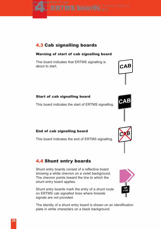
4.3 Cab signalling boards
Warning of start of cab signalling board
This board indicates that ERTMS signalling is
about to start.
Start of cab signalling board
This board indicates the start of ERTMS signalling.
End of cab signalling board
This board indicates the end of ERTMS signalling.
4.4 Shunt entry boards
Shunt entry boards consist of a reflective board
showing a white chevron on a violet background.
The chevron points toward the line to which the
shunt entry board applies.
Shunt entry boards mark the entry of a shunt route
on ERTMS cab signalled lines where lineside
signals are not provided.
The identity of a shunt entry board is shown on an identification
plate in white characters on a black background.
Uncontrolled When Printed Document comes into force and supersedes RS521 Iss 2 on 05/12/2015 Superseded by RS521 Iss 4 with effect from 03/12/2016
31
5 Other signals and indicators
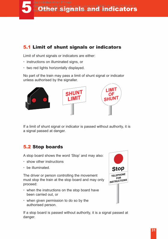
5.1 Limit of shunt signals or indicators
Limit of shunt signals or indicators are either:
• instructions on illuminated signs, or
• two red lights horizontally displayed.
No part of the train may pass a limit of shunt signal or indicator
unless authorised by the signaller.
If a limit of shunt signal or indicator is passed without authority, it is
a signal passed at danger.
5.2 Stop boards
A stop board shows the word ‘Stop’ and may also:
• show other instructions
• be illuminated.
The driver or person controlling the movement
must stop the train at the stop board and may only
proceed:
• when the instructions on the stop board have
been carried out, or
• when given permission to do so by the
authorised person.
If a stop board is passed without authority, it is a signal passed at
danger.
Uncontrolled When Printed Document comes into force and supersedes RS521 Iss 2 on 05/12/2015 Superseded by RS521 Iss 4 with effect from 03/12/2016

32
5 Other signals and indicators
5.3 Possession limit boards (PLB)
A PLB identifies the boundary of a possession. They may also be
used as part of the protection for a line blockage.
The board is red, double-sided and is visible along the line in both
directions.
It will also have a steady or flashing red light visible along the line
in both directions.
If a PLB is passed without authority, it is a signal passed at danger.
Uncontrolled When Printed Document comes into force and supersedes RS521 Iss 2 on 05/12/2015 Superseded by RS521 Iss 4 with effect from 03/12/2016
5 Other signals and indicators
33
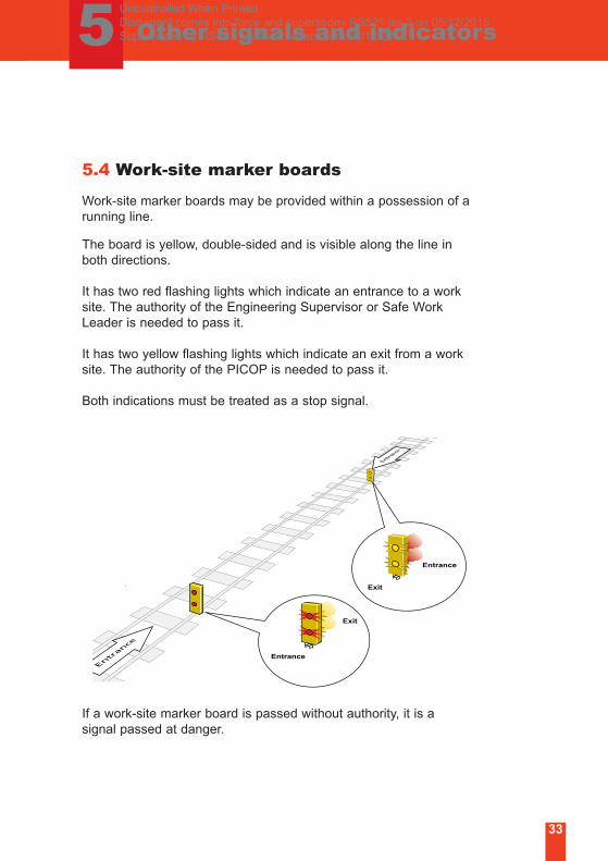
5.4 Work-site marker boards
Work-site marker boards may be provided within a possession of a
running line.
The board is yellow, double-sided and is visible along the line in
both directions.
It has two red flashing lights which indicate an entrance to a work
site. The authority of the Engineering Supervisor or Safe Work
Leader is needed to pass it.
It has two yellow flashing lights which indicate an exit from a work
site. The authority of the PICOP is needed to pass it.
Both indications must be treated as a stop signal.
If a work-site marker board is passed without authority, it is a
signal passed at danger.
Entrance
Exit
Entrance
Exit
Uncontrolled When Printed Document comes into force and supersedes RS521 Iss 2 on 05/12/2015 Superseded by RS521 Iss 4 with effect from 03/12/2016
5 Other signals and indicators
34
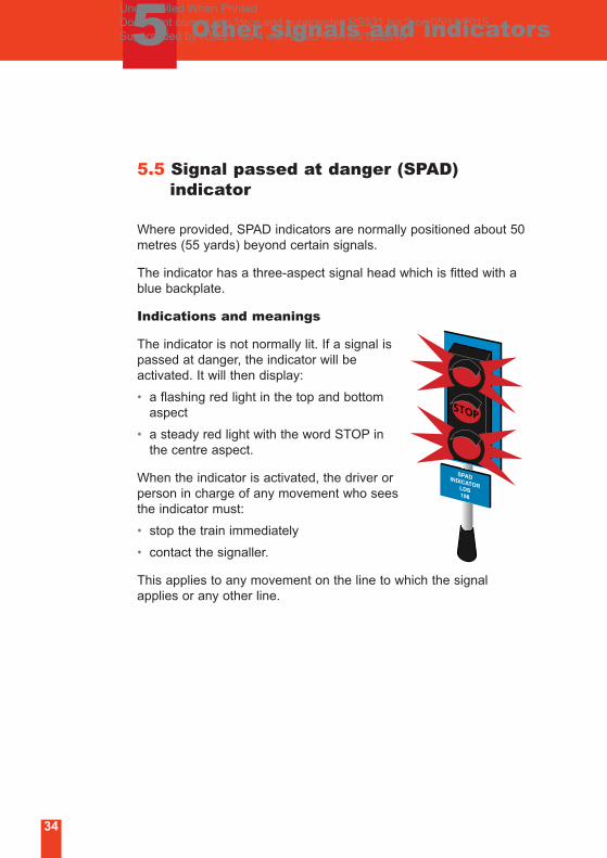
5.5 Signal passed at danger (SPAD) indicator
Where provided, SPAD indicators are normally positioned about 50
metres (55 yards) beyond certain signals.
The indicator has a three-aspect signal head which is fitted with a
blue backplate.
Indications and meanings
The indicator is not normally lit. If a signal is
passed at danger, the indicator will be
activated. It will then display:
• a flashing red light in the top and bottom
aspect
• a steady red light with the word STOP in
the centre aspect.
When the indicator is activated, the driver or
person in charge of any movement who sees
the indicator must:
• stop the train immediately
• contact the signaller.
This applies to any movement on the line to which the signal
applies or any other line.
Uncontrolled When Printed Document comes into force and supersedes RS521 Iss 2 on 05/12/2015 Superseded by RS521 Iss 4 with effect from 03/12/2016
5 Other signals and indicators
35
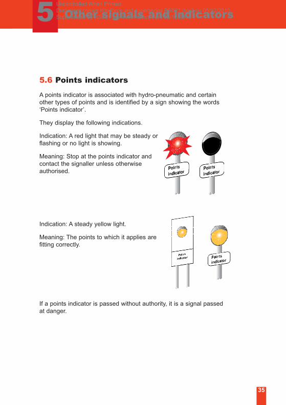
5.6 Points indicators
A points indicator is associated with hydro-pneumatic and certain
other types of points and is identified by a sign showing the words
‘Points indicator’.
They display the following indications.
Indication: A red light that may be steady or
flashing or no light is showing.
Meaning: Stop at the points indicator and
contact the signaller unless otherwise
authorised.
Indication: A steady yellow light.
Meaning: The points to which it applies are
fitting correctly.
If a points indicator is passed without authority, it is a signal passed
at danger.
Uncontrolled When Printed Document comes into force and supersedes RS521 Iss 2 on 05/12/2015 Superseded by RS521 Iss 4 with effect from 03/12/2016
5 Other signals and indicators
36
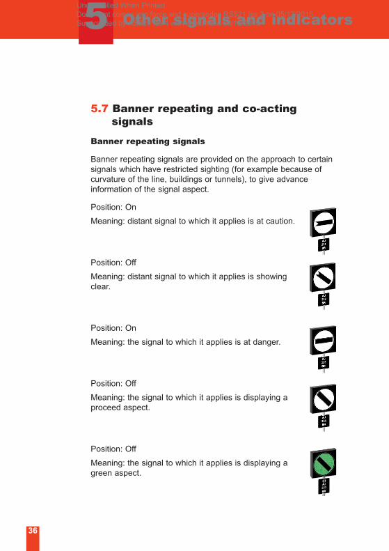
5.7 Banner repeating and co-acting signals
Banner repeating signals
Banner repeating signals are provided on the approach to certain
signals which have restricted sighting (for example because of
curvature of the line, buildings or tunnels), to give advance
information of the signal aspect.
Position: On
Meaning: distant signal to which it applies is at caution.
Position: Off
Meaning: distant signal to which it applies is showing
clear.
Position: On
Meaning: the signal to which it applies is at danger.
Position: Off
Meaning: the signal to which it applies is displaying a
proceed aspect.
Position: Off
Meaning: the signal to which it applies is displaying a
green aspect.
Uncontrolled When Printed Document comes into force and supersedes RS521 Iss 2 on 05/12/2015 Superseded by RS521 Iss 4 with effect from 03/12/2016
5 Other signals and indicators
37
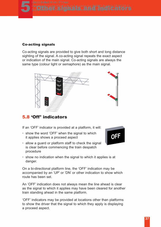
Co-acting signals
Co-acting signals are provided to give both short and long distance
sighting of the signal. A co-acting signal repeats the exact aspect
or indication of the main signal. Co-acting signals are always the
same type (colour light or semaphore) as the main signal.
5.8 ‘Off’ indicators
If an ‘OFF’ indicator is provided at a platform, it will:
• show the word ‘OFF’ when the signal to which
it applies shows a proceed aspect
• allow a guard or platform staff to check the signal
is clear before commencing the train despatch
procedure
• show no indication when the signal to which it applies is at
danger.
On a bi-directional platform line, the ‘OFF’ indication may be
accompanied by an ‘UP’ or ‘DN’ or other indication to show which
route has been set.
An ‘OFF’ indication does not always mean the line ahead is clear
as the signal to which it applies may have been cleared for another
train standing ahead in the same platform.
‘OFF’ indicators may be provided at locations other than platforms
to show the driver that the signal to which they apply is displaying
a proceed aspect.
Uncontrolled When Printed Document comes into force and supersedes RS521 Iss 2 on 05/12/2015 Superseded by RS521 Iss 4 with effect from 03/12/2016
5 Other signals and indicators
38
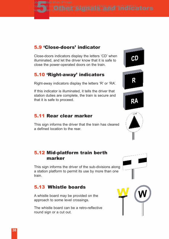
5.9 ‘Close-doors’ indicator
Close-doors indicators display the letters ‘CD’ when
illuminated, and let the driver know that it is safe to
close the power-operated doors on the train.
5.10 ‘Right-away’ indicators
Right-away indicators display the letters ‘R’ or ‘RA’.
If this indicator is illuminated, it tells the driver that
station duties are complete, the train is secure and
that it is safe to proceed.
5.11 Rear clear marker
This sign informs the driver that the train has cleared
a defined location to the rear.
5.12 Mid-platform train berth marker
This sign informs the driver of the sub-divisions along
a station platform to permit its use by more than one
train.
5.13 Whistle boards
A whistle board may be provided on the
approach to some level crossings.
The whistle board can be a retro-reflective
round sign or a cut out.
Uncontrolled When Printed Document comes into force and supersedes RS521 Iss 2 on 05/12/2015 Superseded by RS521 Iss 4 with effect from 03/12/2016
5 Other signals and indicators
39
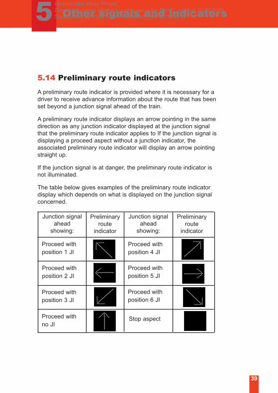
5.14 Preliminary route indicators
A preliminary route indicator is provided where it is necessary for a
driver to receive advance information about the route that has been
set beyond a junction signal ahead of the train.
A preliminary route indicator displays an arrow pointing in the same
direction as any junction indicator displayed at the junction signal
that the preliminary route indicator applies to If the junction signal is
displaying a proceed aspect without a junction indicator, the
associated preliminary route indicator will display an arrow pointing
straight up.
If the junction signal is at danger, the preliminary route indicator is
not illuminated.
The table below gives examples of the preliminary route indicator
display which depends on what is displayed on the junction signal
concerned.
Preliminary
route
indicator
Junction signal
ahead
showing:
Proceed with
position 1 JI
Proceed with
position 2 JI
Proceed with
no JI
Proceed with
position 3 JI
Stop aspect
Proceed with
position 4 JI
Proceed with
position 5 JI
Proceed with
position 6 JI
Junction signal
ahead
showing:
Preliminary
route
indicator
Uncontrolled When Printed Document comes into force and supersedes RS521 Iss 2 on 05/12/2015 Superseded by RS521 Iss 4 with effect from 03/12/2016
5 Other signals and indicators
40
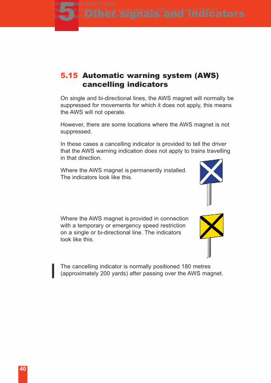
5.15 Automatic warning system (AWS) cancelling indicators
On single and bi-directional lines, the AWS magnet will normally be
suppressed for movements for which it does not apply, this means
the AWS will not operate.
However, there are some locations where the AWS magnet is not
suppressed.
In these cases a cancelling indicator is provided to tell the driver
that the AWS warning indication does not apply to trains travelling
in that direction.
Where the AWS magnet is permanently installed.
The indicators look like this.
Where the AWS magnet is provided in connection
with a temporary or emergency speed restriction
on a single or bi-directional line. The indicators
look like this.
The cancelling indicator is normally positioned 180 metres
(approximately 200 yards) after passing over the AWS magnet.
Uncontrolled When Printed Document comes into force and supersedes RS521 Iss 2 on 05/12/2015 Superseded by RS521 Iss 4 with effect from 03/12/2016

5 Other signals and indicators
41
5.16 AWS gap indicators
In some AWS fitted areas AWS equipment is not provided
throughout. These areas are identified with the following signs.
Where AWS is not provided at a station on a line equipped
with AWS.
Where AWS is not provided in the opposite direction on a
bi-directional line.
For a temporary or emergency speed restriction, AWS will be
provided in both directions.
Start of AWS gap End of AWS gap
Start of the relevant
section of line
concerned
End of the section normal
arrangements resume
Uncontrolled When Printed Document comes into force and supersedes RS521 Iss 2 on 05/12/2015 Superseded by RS521 Iss 4 with effect from 03/12/2016
42
6 Level crossing signs and indicators
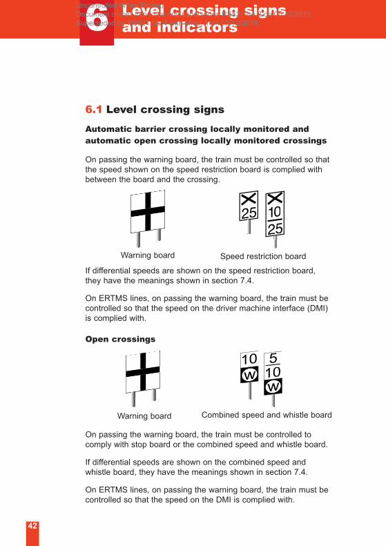
6.1 Level crossing signs
Automatic barrier crossing locally monitored andautomatic open crossing locally monitored crossings
On passing the warning board, the train must be controlled so that
the speed shown on the speed restriction board is complied with
between the board and the crossing.
If differential speeds are shown on the speed restriction board,
they have the meanings shown in section 7.4.
On ERTMS lines, on passing the warning board, the train must be
controlled so that the speed on the driver machine interface (DMI)
is complied with.
Open crossings
On passing the warning board, the train must be controlled to
comply with stop board or the combined speed and whistle board.
If differential speeds are shown on the combined speed and
whistle board, they have the meanings shown in section 7.4.
On ERTMS lines, on passing the warning board, the train must be
controlled so that the speed on the DMI is complied with.
Warning board Speed restriction board
Warning board Combined speed and whistle board
Uncontrolled When Printed Document comes into force and supersedes RS521 Iss 2 on 05/12/2015 Superseded by RS521 Iss 4 with effect from 03/12/2016

Level crossing signs and indicators
43
Wrong-direction boards
Wrong-direction speed restriction boards are
positioned on the approach to level
crossings that have wrong-direction controls.
The speed of the train must be controlled so that the train
complies with the speed shown, between the board and the
crossing. Black numerals on a white background denote mph and
white numerals on a black background denote km/h.
Sighting board on ERTMS lines
This sign indicates the point at which the driver is
required to ensure that the level crossing is clear and
to observe the driver’s level crossing indicator.
6.2 Level crossing indicators
A level crossing indicator is associated with locally monitored level
crossings.
They display the following indications.
Indication: A red light that may be steady or
flashing or no light is showing.
Meaning: Stop before reaching the level
crossing and ensure it is safe before passing
over it.
Indication: A flashing white light.
Meaning: The level crossing is working correctly,
and providing the crossing is clear, it is safe to
proceed over it.
6Uncontrolled When Printed Document comes into force and supersedes RS521 Iss 2 on 05/12/2015 Superseded by RS521 Iss 4 with effect from 03/12/2016
44
7 Speed indicators
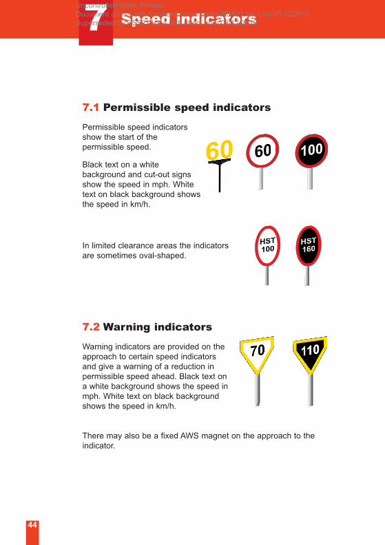
7.1 Permissible speed indicators
Permissible speed indicators
show the start of the
permissible speed.
Black text on a white
background and cut-out signs
show the speed in mph. White
text on black background shows
the speed in km/h.
In limited clearance areas the indicators
are sometimes oval-shaped.
7.2 Warning indicators
Warning indicators are provided on the
approach to certain speed indicators
and give a warning of a reduction in
permissible speed ahead. Black text on
a white background shows the speed in
mph. White text on black background
shows the speed in km/h.
There may also be a fixed AWS magnet on the approach to the
indicator.
Uncontrolled When Printed Document comes into force and supersedes RS521 Iss 2 on 05/12/2015 Superseded by RS521 Iss 4 with effect from 03/12/2016
Speed indicators
45
7
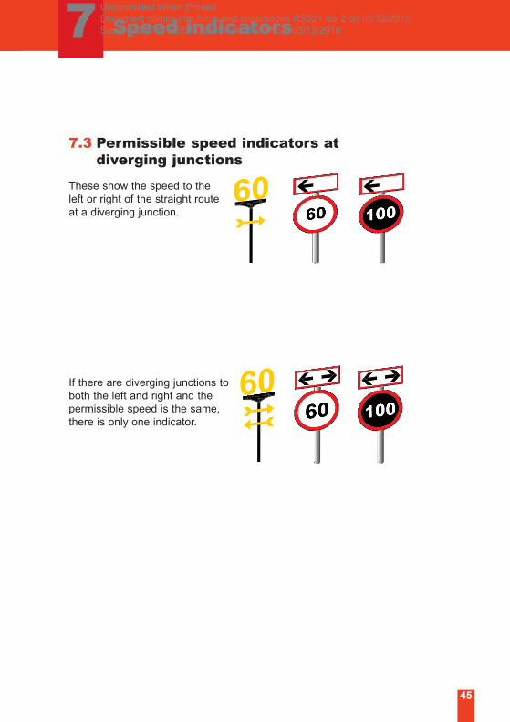
7.3 Permissible speed indicators at diverging junctions
These show the speed to the
left or right of the straight route
at a diverging junction.
If there are diverging junctions to
both the left and right and the
permissible speed is the same,
there is only one indicator.
Uncontrolled When Printed Document comes into force and supersedes RS521 Iss 2 on 05/12/2015 Superseded by RS521 Iss 4 with effect from 03/12/2016
7 Speed indicators
46
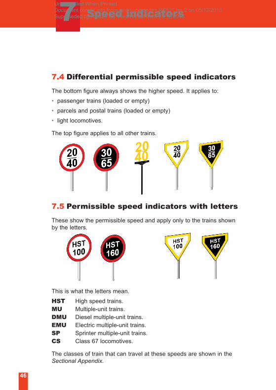
7.4 Differential permissible speed indicators
The bottom figure always shows the higher speed. It applies to:
• passenger trains (loaded or empty)
• parcels and postal trains (loaded or empty)
• light locomotives.
The top figure applies to all other trains.
7.5 Permissible speed indicators with letters
These show the permissible speed and apply only to the trains shown
by the letters.
This is what the letters mean.
HST High speed trains.
MU Multiple-unit trains.
DMU Diesel multiple-unit trains.
EMU Electric multiple-unit trains.
SP Sprinter multiple-unit trains.
CS Class 67 locomotives.
The classes of train that can travel at these speeds are shown in the
Sectional Appendix.
Uncontrolled When Printed Document comes into force and supersedes RS521 Iss 2 on 05/12/2015 Superseded by RS521 Iss 4 with effect from 03/12/2016

7 Speed indicators
47
7.6 Enhanced permissible speed (EPS)indicators
These show the enhanced permissible speed in mph and apply to
tilting trains in tilting mode.
Where differential signs are provided, the bottom figure always
shows the higher speed and applies to class 390 trains in tilting
mode. The top figure applies to class 221 trains in tilting mode.
Warning indicators are provided on
the approach to certain EPS speed
indicators and give a warning of a
reduction in the enhanced
permissible speed ahead.
Uncontrolled When Printed Document comes into force and supersedes RS521 Iss 2 on 05/12/2015 Superseded by RS521 Iss 4 with effect from 03/12/2016
48
8 Speed restriction signs
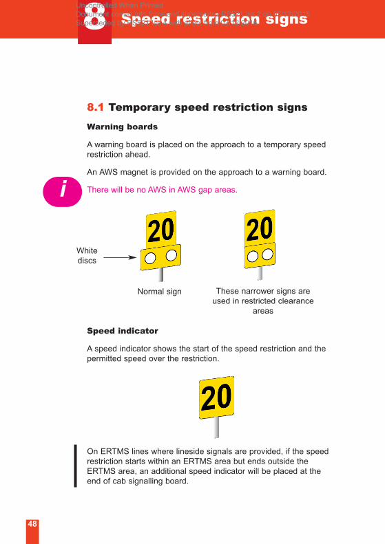
8.1 Temporary speed restriction signs
Warning boards
A warning board is placed on the approach to a temporary speed
restriction ahead.
An AWS magnet is provided on the approach to a warning board.
There will be no AWS in AWS gap areas.
Speed indicator
A speed indicator shows the start of the speed restriction and the
permitted speed over the restriction.
On ERTMS lines where lineside signals are provided, if the speed
restriction starts within an ERTMS area but ends outside the
ERTMS area, an additional speed indicator will be placed at the
end of cab signalling board.
Normal sign These narrower signs are
used in restricted clearance
areas
i
White
discs
Uncontrolled When Printed Document comes into force and supersedes RS521 Iss 2 on 05/12/2015 Superseded by RS521 Iss 4 with effect from 03/12/2016
Speed restriction signs
49
8
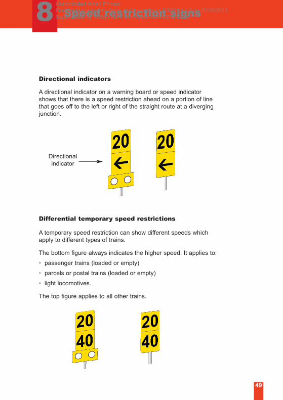
Directional indicators
A directional indicator on a warning board or speed indicator
shows that there is a speed restriction ahead on a portion of line
that goes off to the left or right of the straight route at a diverging
junction.
Differential temporary speed restrictions
A temporary speed restriction can show different speeds which
apply to different types of trains.
The bottom figure always indicates the higher speed. It applies to:
• passenger trains (loaded or empty)
• parcels or postal trains (loaded or empty)
• light locomotives.
The top figure applies to all other trains.
Directional
indicator
Uncontrolled When Printed Document comes into force and supersedes RS521 Iss 2 on 05/12/2015 Superseded by RS521 Iss 4 with effect from 03/12/2016
8 Speed restriction signs
50
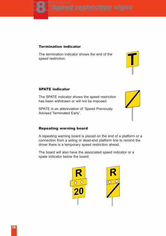
Termination indicator
The termination indicator shows the end of the
speed restriction.
SPATE indicator
The SPATE indicator shows the speed restriction
has been withdrawn or will not be imposed.
SPATE is an abbreviation of ‘Speed Previously
Advised Terminated Early’.
Repeating warning board
A repeating warning board is placed on the end of a platform or a
connection from a siding or dead-end platform line to remind the
driver there is a temporary speed restriction ahead.
The board will also have the associated speed indicator or a
spate indicator below the board.
Uncontrolled When Printed Document comes into force and supersedes RS521 Iss 2 on 05/12/2015 Superseded by RS521 Iss 4 with effect from 03/12/2016
8 Speed restriction signs
51
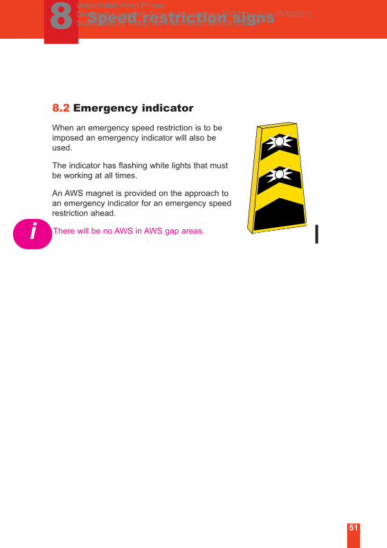
8.2 Emergency indicator
When an emergency speed restriction is to be
imposed an emergency indicator will also be
used.
The indicator has flashing white lights that must
be working at all times.
An AWS magnet is provided on the approach to
an emergency indicator for an emergency speed
restriction ahead.
There will be no AWS in AWS gap areas.i
Uncontrolled When Printed Document comes into force and supersedes RS521 Iss 2 on 05/12/2015 Superseded by RS521 Iss 4 with effect from 03/12/2016
52
9 AC electrified line signs
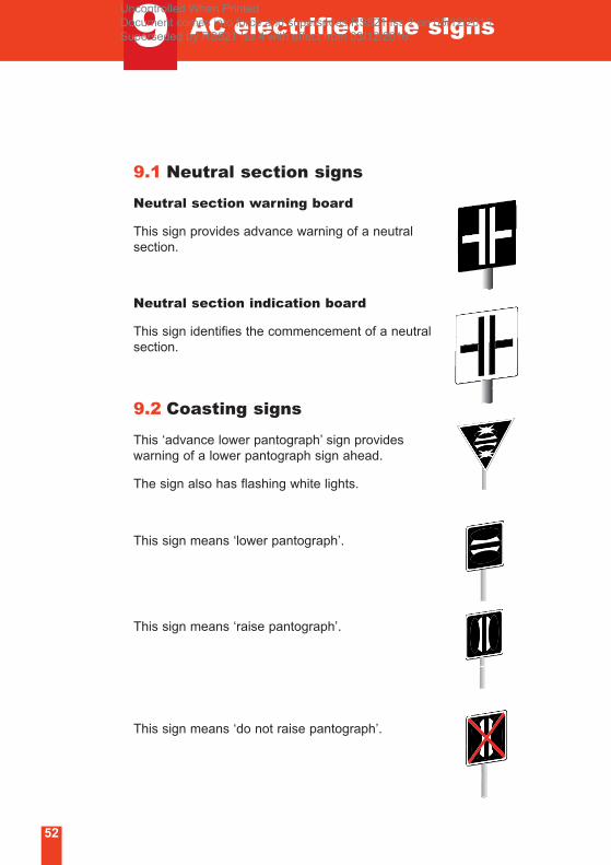
9.1 Neutral section signs
Neutral section warning board
This sign provides advance warning of a neutral
section.
Neutral section indication board
This sign identifies the commencement of a neutral
section.
9.2 Coasting signs
This ‘advance lower pantograph’ sign provides
warning of a lower pantograph sign ahead.
The sign also has flashing white lights.
This sign means ‘lower pantograph’.
This sign means ‘raise pantograph’.
This sign means ‘do not raise pantograph’.
Uncontrolled When Printed Document comes into force and supersedes RS521 Iss 2 on 05/12/2015 Superseded by RS521 Iss 4 with effect from 03/12/2016
53
10 Radio signs
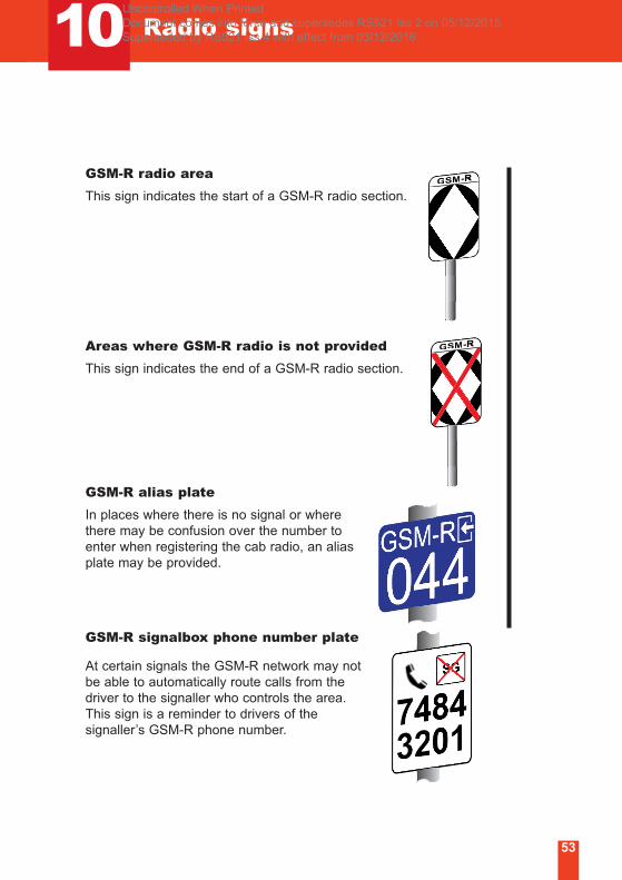
GSM-R radio area
This sign indicates the start of a GSM-R radio section.
Areas where GSM-R radio is not provided
This sign indicates the end of a GSM-R radio section.
GSM-R alias plate
In places where there is no signal or where
there may be confusion over the number to
enter when registering the cab radio, an alias
plate may be provided.
GSM-R signalbox phone number plate
At certain signals the GSM-R network may not
be able to automatically route calls from the
driver to the signaller who controls the area.
This sign is a reminder to drivers of the
signaller’s GSM-R phone number.
Uncontrolled When Printed Document comes into force and supersedes RS521 Iss 2 on 05/12/2015 Superseded by RS521 Iss 4 with effect from 03/12/2016
54
10 Radio signs
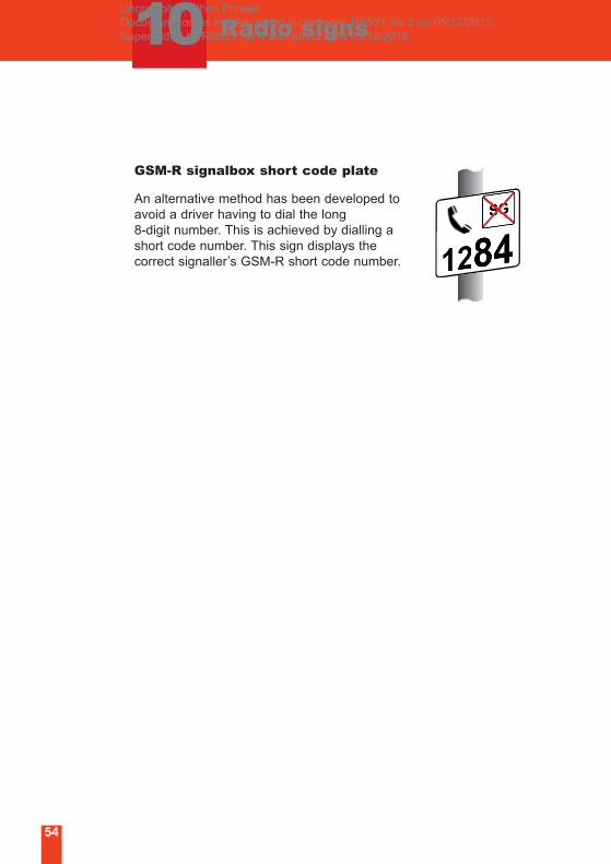
GSM-R signalbox short code plate
An alternative method has been developed to
avoid a driver having to dial the long
8-digit number. This is achieved by dialling a
short code number. This sign displays the
correct signaller’s GSM-R short code number.
Uncontrolled When Printed Document comes into force and supersedes RS521 Iss 2 on 05/12/2015 Superseded by RS521 Iss 4 with effect from 03/12/2016
11 Telephone signs
55
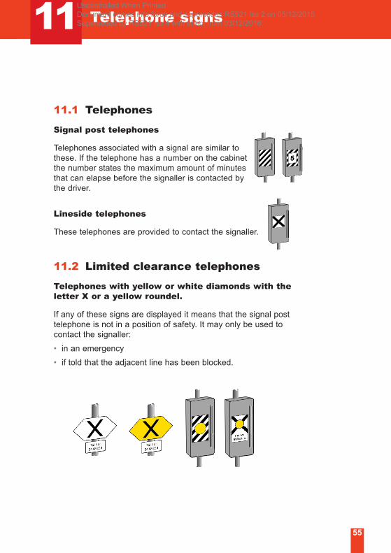
11.1 Telephones
Signal post telephones
Telephones associated with a signal are similar to
these. If the telephone has a number on the cabinet
the number states the maximum amount of minutes
that can elapse before the signaller is contacted by
the driver.
Lineside telephones
These telephones are provided to contact the signaller.
11.2 Limited clearance telephones
Telephones with yellow or white diamonds with theletter X or a yellow roundel.
If any of these signs are displayed it means that the signal post
telephone is not in a position of safety. It may only be used to
contact the signaller:
• in an emergency
• if told that the adjacent line has been blocked.
Uncontrolled When Printed Document comes into force and supersedes RS521 Iss 2 on 05/12/2015 Superseded by RS521 Iss 4 with effect from 03/12/2016
56
11 Telephone signs
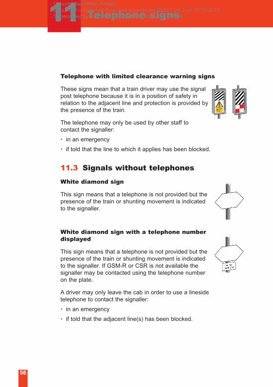
Telephone with limited clearance warning signs
These signs mean that a train driver may use the signal
post telephone because it is in a position of safety in
relation to the adjacent line and protection is provided by
the presence of the train.
The telephone may only be used by other staff to
contact the signaller:
• in an emergency
• if told that the line to which it applies has been blocked.
11.3 Signals without telephones
White diamond sign
This sign means that a telephone is not provided but the
presence of the train or shunting movement is indicated
to the signaller.
White diamond sign with a telephone numberdisplayed
This sign means that a telephone is not provided but the
presence of the train or shunting movement is indicated
to the signaller. If GSM-R or CSR is not available the
signaller may be contacted using the telephone number
on the plate.
A driver may only leave the cab in order to use a lineside
telephone to contact the signaller:
• in an emergency
• if told that the adjacent line(s) has been blocked.
Uncontrolled When Printed Document comes into force and supersedes RS521 Iss 2 on 05/12/2015 Superseded by RS521 Iss 4 with effect from 03/12/2016
57
12 Other lineside signs
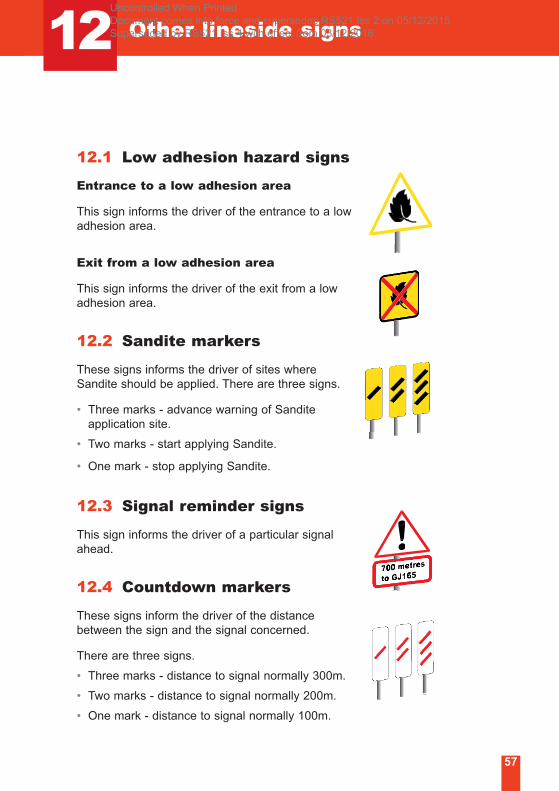
12.1 Low adhesion hazard signs
Entrance to a low adhesion area
This sign informs the driver of the entrance to a low
adhesion area.
Exit from a low adhesion area
This sign informs the driver of the exit from a low
adhesion area.
12.2 Sandite markers
These signs informs the driver of sites where
Sandite should be applied. There are three signs.
• Three marks - advance warning of Sandite
application site.
• Two marks - start applying Sandite.
• One mark - stop applying Sandite.
12.3 Signal reminder signs
This sign informs the driver of a particular signal
ahead.
12.4 Countdown markers
These signs inform the driver of the distance
between the sign and the signal concerned.
There are three signs.
• Three marks - distance to signal normally 300m.
• Two marks - distance to signal normally 200m.
• One mark - distance to signal normally 100m.
Uncontrolled When Printed Document comes into force and supersedes RS521 Iss 2 on 05/12/2015 Superseded by RS521 Iss 4 with effect from 03/12/2016
58
12 Other lineside signs
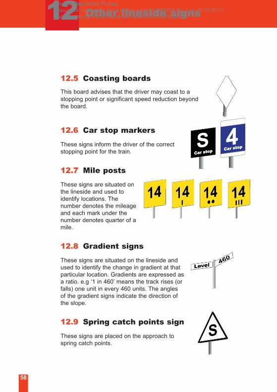
12.5 Coasting boards
This board advises that the driver may coast to a
stopping point or significant speed reduction beyond
the board.
12.6 Car stop markers
These signs inform the driver of the correct
stopping point for the train.
12.7 Mile posts
These signs are situated on
the lineside and used to
identify locations. The
number denotes the mileage
and each mark under the
number denotes quarter of a
mile.
12.8 Gradient signs
These signs are situated on the lineside and
used to identify the change in gradient at that
particular location. Gradients are expressed as
a ratio. e.g ‘1 in 460’ means the track rises (or
falls) one unit in every 460 units. The angles
of the gradient signs indicate the direction of
the slope.
12.9 Spring catch points sign
These signs are placed on the approach to
spring catch points.
Uncontrolled When Printed Document comes into force and supersedes RS521 Iss 2 on 05/12/2015 Superseded by RS521 Iss 4 with effect from 03/12/2016
12 Other lineside signs
59
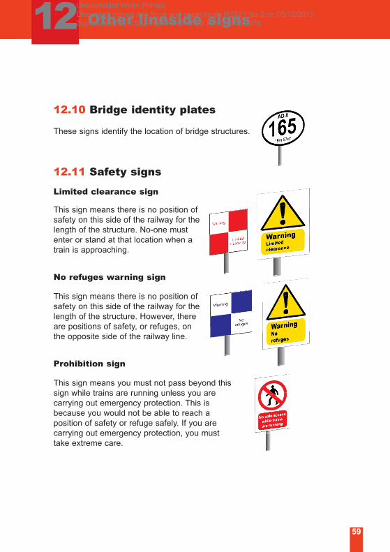
12.10 Bridge identity plates
These signs identify the location of bridge structures.
12.11 Safety signs
Limited clearance sign
This sign means there is no position of
safety on this side of the railway for the
length of the structure. No-one must
enter or stand at that location when a
train is approaching.
No refuges warning sign
This sign means there is no position of
safety on this side of the railway for the
length of the structure. However, there
are positions of safety, or refuges, on
the opposite side of the railway line.
Prohibition sign
This sign means you must not pass beyond this
sign while trains are running unless you are
carrying out emergency protection. This is
because you would not be able to reach a
position of safety or refuge safely. If you are
carrying out emergency protection, you must
take extreme care.
Uncontrolled When Printed Document comes into force and supersedes RS521 Iss 2 on 05/12/2015 Superseded by RS521 Iss 4 with effect from 03/12/2016
60
13 Lineside handsignals
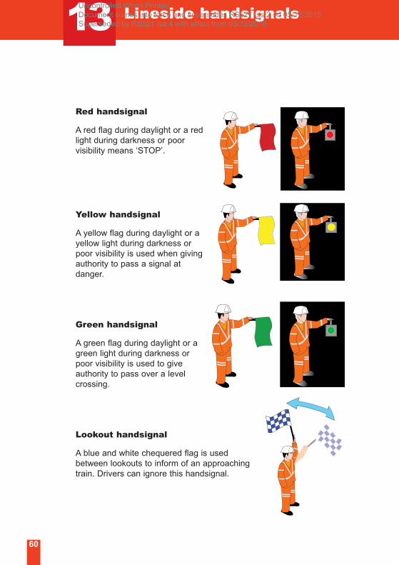
Red handsignal
A red flag during daylight or a red
light during darkness or poor
visibility means ‘STOP’.
Yellow handsignal
A yellow flag during daylight or a
yellow light during darkness or
poor visibility is used when giving
authority to pass a signal at
danger.
Green handsignal
A green flag during daylight or a
green light during darkness or
poor visibility is used to give
authority to pass over a level
crossing.
Lookout handsignal
A blue and white chequered flag is used
between lookouts to inform of an approaching
train. Drivers can ignore this handsignal.
Uncontrolled When Printed Document comes into force and supersedes RS521 Iss 2 on 05/12/2015 Superseded by RS521 Iss 4 with effect from 03/12/2016

Uncontrolled When Printed Document comes into force and supersedes RS521 Iss 2 on 05/12/2015 Superseded by RS521 Iss 4 with effect from 03/12/2016
Published by
Uncontrolled When Printed Document comes into force and supersedes RS521 Iss 2 on 05/12/2015 Superseded by RS521 Iss 4 with effect from 03/12/2016