HANDBOOK OF WESTERN RECLAMATION TECHNIQUES - Utah · Handbook of Western Reclamation Techniques...
504
HANDBOOK OF WESTERN RECLAMATION TECHNIQUES table of contents
Transcript of HANDBOOK OF WESTERN RECLAMATION TECHNIQUES - Utah · Handbook of Western Reclamation Techniques...

HANDBOOK OFWESTERN
RECLAMATIONTECHNIQUES
table of contents

HANDBOOK OF
WESTERN
RECLAMATION TECHNIQUES
by:
Frank K. FerrisLarry H. Kleinman
D.G. StewardRobert R. Stowe
Laurel E. VicklundJohn D. BerryRobert Cowan
Claire Gabriel DunneRichard DunneDoyl M. Fritz
Roy L. GarrisonRobert K. Green
Marlys M. HansenC. Marty JonesGreg E. Jones
Christopher D. LidstoneMarilee G. O'RourkeBonnie C. PostovitHoward R. Postovit
R.S. ShinnPatrick T. Tyrrell
Richard C. WarnerKenneth L. Wrede

Permission is granted for the public to duplicate any part of this work, but permission should berequested from the authors to publish or incorporate any of this material into another document.Inquiries about this book can be presented to Frank K. Ferris, and questions or comments can bedirected to the individual authors at the addresses presented in the List of Contributing Authors.
These varied techniques have worked or are working for the technique author(s). However, theauthor(s) or editor(s) cannot warrant a technique. Sites, contractors, materials, specifications, andexpectations differ.
Publish Date: 12/31/96
For additional copies, please contact:
The Office of Technology TransferWestern Regional Coordinating CenterOffice of Surface Mining Reclamation and Enforcement1999 Broadway, Suite 3320Denver, CO 80202-5733
Voice: (303) 844-1448Fax: (303) 844-1522E-mail: [email protected]

Handbook of Western Reclamation Techniques Page i
ACKNOWLEDGEMENTS
This work was supported in part by the Abandoned Coal Mine Lands (ACML) Research
Program at the University of Wyoming. This support was administered by the Wyoming
Department of Environmental Quality, Land Quality Division from funds returned to
Wyoming from the Office of Surface Mining of the U.S. Department of Interior.
University of Wyoming sponsors and coordinators:
William Gern
Angela Powell
Roger Wilmot
Office of Surface Mining sponsors and coordinators:
Linda Wagner
Joe Galetovic
Additional support has been provided by:
The Carter Mining Company
Centralia Mining Company
Cyprus-AMAX/Amax Coal West, Inc.
Horizons, Inc.
Kennecott Energy / Cordero Mining Company
Kerr McGee Coal Corporation, Jacobs Ranch Mine
Kiewit Mining Group
Lidstone & Anderson, Inc.
Powder River Coal Company
Powder River Eagle Studies, Inc.
Thunder Basin Coal Company - ARCO
States West Water Resources Corp.
Western Water Consultants
Wind River Seed
Wyodak Resources Development Corp.
We would also like to express our appreciation to Excelcad in Gillette, Wyoming for the donated
portion of the drafting work.
We are grateful to the Office of Technology Transfer, Western Regional Coordinating Center,
Office of Surface Mining for assistance with the technology transfer of this handbook.

Handbook of Western Reclamation Techniques Page ii
EDITORS
Management Committee:
Frank K. Ferris
Larry H. Kleinman
D. G. Steward
Robert R. Stowe
Laurel E. Vicklund
Managing Editor:
Marlys M. Hansen
Associate Editors:
Wendy S. Hutchinson
Roy S. Liedtke
Section Editors:
Frank K. Ferris
Larry H. Kleinman
Bonnie C. Postovit
D. G. Steward
Robert R. Stowe
Laurel E. Vicklund

Handbook of Western Reclamation Techniques Page iii
TABLE OF CONTENTS
Introduction . . . . . . . . . . . . . . . . . . . . . . . . . . . . . . . . . . . . . . . . . . . . . . . . . . . . . . . . . . . . . . . 1
References . . . . . . . . . . . . . . . . . . . . . . . . . . . . . . . . . . . . . . . . . . . . . . . . . . . . . . . . . . . . . . . 3
List of Contributing Authors . . . . . . . . . . . . . . . . . . . . . . . . . . . . . . . . . . . . . . . . . . . . . . . . . . . 6
Section I: TOPSOIL
A. Introduction . . . . . . . . . . . . . . . . . . . . . . . . . . . . . . . . . . . . . . . . . . . . . . . . . . . . . . . . I-1
B. Salvage . . . . . . . . . . . . . . . . . . . . . . . . . . . . . . . . . . . . . . . . . . . . . . . . . . . . . . . . . . . I-3
1. Topsoil Identification and Salvage Control . . . . . . . . . . . . . . . . . . . . . . . . . . . . . I-3
2. Topsoil Stripping . . . . . . . . . . . . . . . . . . . . . . . . . . . . . . . . . . . . . . . . . . . . . . . . I-11
3. Topsoil Stockpiling . . . . . . . . . . . . . . . . . . . . . . . . . . . . . . . . . . . . . . . . . . . . . . I-15
4. Topsoil Stripping Equipment . . . . . . . . . . . . . . . . . . . . . . . . . . . . . . . . . . . . . . . I-17
C. Replacement . . . . . . . . . . . . . . . . . . . . . . . . . . . . . . . . . . . . . . . . . . . . . . . . . . . . . . I-19
1. Topsoil Replacement Depths . . . . . . . . . . . . . . . . . . . . . . . . . . . . . . . . . . . . . . I-19
2. Topsoil Replacement . . . . . . . . . . . . . . . . . . . . . . . . . . . . . . . . . . . . . . . . . . . . . I-23
3. Elevation Control . . . . . . . . . . . . . . . . . . . . . . . . . . . . . . . . . . . . . . . . . . . . . . . I-27
4. Preserving Seedbed Viability Through Direct Haul
of Frozen Topsoil . . . . . . . . . . . . . . . . . . . . . . . . . . . . . . . . . . . . . . . . . . . . . . . I-31
D. References . . . . . . . . . . . . . . . . . . . . . . . . . . . . . . . . . . . . . . . . . . . . . . . . . . . . . . . I-33
Section II: HYDROLOGY
A. Introduction . . . . . . . . . . . . . . . . . . . . . . . . . . . . . . . . . . . . . . . . . . . . . . . . . . . . . . . . II-1
B. Control Structures . . . . . . . . . . . . . . . . . . . . . . . . . . . . . . . . . . . . . . . . . . . . . . . . . . . II-3
1. Sediment Control Basin Design and Construction . . . . . . . . . . . . . . . . . . . . . . . . II-3
2. Diversion Design and Construction . . . . . . . . . . . . . . . . . . . . . . . . . . . . . . . . . . II-13
3. Drop Structures . . . . . . . . . . . . . . . . . . . . . . . . . . . . . . . . . . . . . . . . . . . . . . . . . II-21
4. Backfill Impoundments . . . . . . . . . . . . . . . . . . . . . . . . . . . . . . . . . . . . . . . . . . . II-33
C. Alternative Sediment Control . . . . . . . . . . . . . . . . . . . . . . . . . . . . . . . . . . . . . . . . . . II-45
1. Straw or Hay Bale Check Dams . . . . . . . . . . . . . . . . . . . . . . . . . . . . . . . . . . . . II-45
2. Rock Check Dams . . . . . . . . . . . . . . . . . . . . . . . . . . . . . . . . . . . . . . . . . . . . . . II-49
3. Sediment Fence . . . . . . . . . . . . . . . . . . . . . . . . . . . . . . . . . . . . . . . . . . . . . . . . II-53
4. Gabion Baskets . . . . . . . . . . . . . . . . . . . . . . . . . . . . . . . . . . . . . . . . . . . . . . . . . II-59
5. Vegetative Filters . . . . . . . . . . . . . . . . . . . . . . . . . . . . . . . . . . . . . . . . . . . . . . . II-65
D. Reconstuction of Hydrologic Features . . . . . . . . . . . . . . . . . . . . . . . . . . . . . . . . . . . II-67
1. Small Drainage Waterway Construction . . . . . . . . . . . . . . . . . . . . . . . . . . . . . . II-67
2. Stream Channel Construction . . . . . . . . . . . . . . . . . . . . . . . . . . . . . . . . . . . . . . II-75
3. Wetlands Reconstruction . . . . . . . . . . . . . . . . . . . . . . . . . . . . . . . . . . . . . . . . . II-83

Handbook of Western Reclamation Techniques Page iv
4. Special Considerations in Planning and Constructing
Permanent Postmining Impoundments . . . . . . . . . . . . . . . . . . . . . . . . . . . . . . . II-93
E. Hydrologic Control Structure Tolerances . . . . . . . . . . . . . . . . . . . . . . . . . . . . . . . . II-103
F. Surface Water Monitoring Using a Weir . . . . . . . . . . . . . . . . . . . . . . . . . . . . . . . . . II-113
G. References . . . . . . . . . . . . . . . . . . . . . . . . . . . . . . . . . . . . . . . . . . . . . . . . . . . . . . II-117
H. Citations . . . . . . . . . . . . . . . . . . . . . . . . . . . . . . . . . . . . . . . . . . . . . . . . . . . . . . . . . II-120
Section III: TOPOGRAPHY
A. Introduction . . . . . . . . . . . . . . . . . . . . . . . . . . . . . . . . . . . . . . . . . . . . . . . . . . . . . . . III-1
B. Hills/Slopes . . . . . . . . . . . . . . . . . . . . . . . . . . . . . . . . . . . . . . . . . . . . . . . . . . . . . . . III-3
1. Hillslope Shaping and Morphology . . . . . . . . . . . . . . . . . . . . . . . . . . . . . . . . . . III-3
2. Backfill Grading Observations . . . . . . . . . . . . . . . . . . . . . . . . . . . . . . . . . . . . III-13
3. Evaluation and Comparison
of Topographic Descriptive Methods . . . . . . . . . . . . . . . . . . . . . . . . . . . . . . . III-19
C. References . . . . . . . . . . . . . . . . . . . . . . . . . . . . . . . . . . . . . . . . . . . . . . . . . . . . . . III-25
Section IV: WILDLIFE MITIGATION AND PROTECTION
A. Introduction . . . . . . . . . . . . . . . . . . . . . . . . . . . . . . . . . . . . . . . . . . . . . . . . . . . . . . . IV-1
B. Practices During Mining . . . . . . . . . . . . . . . . . . . . . . . . . . . . . . . . . . . . . . . . . . . . . . IV-3
1. Fencing Practices and Wildlife . . . . . . . . . . . . . . . . . . . . . . . . . . . . . . . . . . . . . IV-3
2. Reducing Powerline Hazards . . . . . . . . . . . . . . . . . . . . . . . . . . . . . . . . . . . . . . IV-7
3. Traffic and Roadways . . . . . . . . . . . . . . . . . . . . . . . . . . . . . . . . . . . . . . . . . . . IV-13
4. Providing Interim Wildlife Habitat . . . . . . . . . . . . . . . . . . . . . . . . . . . . . . . . . . . IV-15
5. Raptor Nest Relocation . . . . . . . . . . . . . . . . . . . . . . . . . . . . . . . . . . . . . . . . . . IV-25
6. Animal Control . . . . . . . . . . . . . . . . . . . . . . . . . . . . . . . . . . . . . . . . . . . . . . . . IV-27
C. References . . . . . . . . . . . . . . . . . . . . . . . . . . . . . . . . . . . . . . . . . . . . . . . . . . . . . . IV-37
Section V: VEGETATION
A. Introduction . . . . . . . . . . . . . . . . . . . . . . . . . . . . . . . . . . . . . . . . . . . . . . . . . . . . . . . V-1
B. Establishing and Implementing a Revegetation Program . . . . . . . . . . . . . . . . . . . . . V-3
1. Preparing a Revegetation Package . . . . . . . . . . . . . . . . . . . . . . . . . . . . . . . . . V-3
2. Cultivation Practices . . . . . . . . . . . . . . . . . . . . . . . . . . . . . . . . . . . . . . . . . . . . V-11
3. Drill Seeding Practices . . . . . . . . . . . . . . . . . . . . . . . . . . . . . . . . . . . . . . . . . . V-17
4. Hydroseeding Practices . . . . . . . . . . . . . . . . . . . . . . . . . . . . . . . . . . . . . . . . . V-23
5. Mulching Practices . . . . . . . . . . . . . . . . . . . . . . . . . . . . . . . . . . . . . . . . . . . . . V-27
6. Seed Handling . . . . . . . . . . . . . . . . . . . . . . . . . . . . . . . . . . . . . . . . . . . . . . . . V-33
7. Planting Methods for Permanent Reclamation . . . . . . . . . . . . . . . . . . . . . . . . V-37
8. Broadcast Seeding . . . . . . . . . . . . . . . . . . . . . . . . . . . . . . . . . . . . . . . . . . . . . V-39
9. Transplanting Live Plants and Planting Plant Parts . . . . . . . . . . . . . . . . . . . . V-41

Handbook of Western Reclamation Techniques Page v
10. Reforestation . . . . . . . . . . . . . . . . . . . . . . . . . . . . . . . . . . . . . . . . . . . . . . . . . . V-45
11. Seeding Shrub Seed . . . . . . . . . . . . . . . . . . . . . . . . . . . . . . . . . . . . . . . . . . . . V-49
C. Seed Ordering Methods . . . . . . . . . . . . . . . . . . . . . . . . . . . . . . . . . . . . . . . . . . . . . V-55
1. Ordering Seed . . . . . . . . . . . . . . . . . . . . . . . . . . . . . . . . . . . . . . . . . . . . . . . . V-55
2. Preparing a Seed Purchase Request . . . . . . . . . . . . . . . . . . . . . . . . . . . . . . . V-57
3. Warm Season Grasses -- The Importance or Origin of
Named Varieties and Native Harvests . . . . . . . . . . . . . . . . . . . . . . . . . . . . . . V-61
4. Certified Blue-tag Versus Non-certified (Common) Seed . . . . . . . . . . . . . . . V-65
5. Source-identified Yellow-tagged Seed . . . . . . . . . . . . . . . . . . . . . . . . . . . . . . V-67
6. Understanding Seed Tests . . . . . . . . . . . . . . . . . . . . . . . . . . . . . . . . . . . . . . . V-69
7. Determining Pure Live Seed . . . . . . . . . . . . . . . . . . . . . . . . . . . . . . . . . . . . . . V-75
8. Selecting Good Shrub Seed . . . . . . . . . . . . . . . . . . . . . . . . . . . . . . . . . . . . . . V-77
D. Surface Stabilization . . . . . . . . . . . . . . . . . . . . . . . . . . . . . . . . . . . . . . . . . . . . . . . V-83
1. Vegetative Surface Stabilization . . . . . . . . . . . . . . . . . . . . . . . . . . . . . . . . . . . V-83
2. Non-vegetative Surface Stabilization . . . . . . . . . . . . . . . . . . . . . . . . . . . . . . . . V-87
E. Husbandry . . . . . . . . . . . . . . . . . . . . . . . . . . . . . . . . . . . . . . . . . . . . . . . . . . . . . . . V-89
1. Mowing for Weed Control . . . . . . . . . . . . . . . . . . . . . . . . . . . . . . . . . . . . . . . . V-89
2. Burning to Enhance Vegetation . . . . . . . . . . . . . . . . . . . . . . . . . . . . . . . . . . . V-91
3. Husbandry Grazing . . . . . . . . . . . . . . . . . . . . . . . . . . . . . . . . . . . . . . . . . . . . . V-93
F. Monitoring . . . . . . . . . . . . . . . . . . . . . . . . . . . . . . . . . . . . . . . . . . . . . . . . . . . . . . . V-97
1. Vegetation Sampling . . . . . . . . . . . . . . . . . . . . . . . . . . . . . . . . . . . . . . . . . . . V-97
2. Recordkeeping Practices . . . . . . . . . . . . . . . . . . . . . . . . . . . . . . . . . . . . . . . . V-107
3. Electronic Document Management in Mining . . . . . . . . . . . . . . . . . . . . . . . . . V-113
G. References . . . . . . . . . . . . . . . . . . . . . . . . . . . . . . . . . . . . . . . . . . . . . . . . . . . . . . V-119
Section VI: POSTMINING LAND USE
A. Introduction . . . . . . . . . . . . . . . . . . . . . . . . . . . . . . . . . . . . . . . . . . . . . . . . . . . . . . . VI-1
B. Grazing . . . . . . . . . . . . . . . . . . . . . . . . . . . . . . . . . . . . . . . . . . . . . . . . . . . . . . . . . . VI-3
1. Early Implementation of Postmining Land Use - Grazing as Husbandry . . . . . . VI-3
2. Establishing and Controlling a Grazing Program on the Mine Site;
Initial Planning . . . . . . . . . . . . . . . . . . . . . . . . . . . . . . . . . . . . . . . . . . . . . . . . . . VI-7
3. Establishing and Controlling a Grazing Program on the Mine Site;
Writing the Grazing Contract . . . . . . . . . . . . . . . . . . . . . . . . . . . . . . . . . . . . . . VI-15
4. Establishing and Controlling a Grazing Program on the Mine Site;
Implementation . . . . . . . . . . . . . . . . . . . . . . . . . . . . . . . . . . . . . . . . . . . . . . . . VI-19
5. Creating Livestock Pastures . . . . . . . . . . . . . . . . . . . . . . . . . . . . . . . . . . . . . . VI-23
6. Water Sources for Livestock . . . . . . . . . . . . . . . . . . . . . . . . . . . . . . . . . . . . . . VI-33
7. Moving Livestock . . . . . . . . . . . . . . . . . . . . . . . . . . . . . . . . . . . . . . . . . . . . . . . VI-45
8. Vegetation Quality for Grazing . . . . . . . . . . . . . . . . . . . . . . . . . . . . . . . . . . . . VI-53

Handbook of Western Reclamation Techniques Page vi
9. Timing of Grazing . . . . . . . . . . . . . . . . . . . . . . . . . . . . . . . . . . . . . . . . . . . . . . VI-57
10. Grazing, Wildlife, and Wildlife Habitat . . . . . . . . . . . . . . . . . . . . . . . . . . . . . . VI-65
C. Wildlife . . . . . . . . . . . . . . . . . . . . . . . . . . . . . . . . . . . . . . . . . . . . . . . . . . . . . . . . . . VI-69
1. Forage Enhancement for Wildlife . . . . . . . . . . . . . . . . . . . . . . . . . . . . . . . . . . VI-69
2. Water Resources . . . . . . . . . . . . . . . . . . . . . . . . . . . . . . . . . . . . . . . . . . . . . . VI-71
3. Rockpile Design and Construction . . . . . . . . . . . . . . . . . . . . . . . . . . . . . . . . . . VI-75
D. References . . . . . . . . . . . . . . . . . . . . . . . . . . . . . . . . . . . . . . . . . . . . . . . . . . . . . . VI-83
E. Citations . . . . . . . . . . . . . . . . . . . . . . . . . . . . . . . . . . . . . . . . . . . . . . . . . . . . . . . . . VI-84
Section VII: DRILLING PROGRAM
A. Introduction . . . . . . . . . . . . . . . . . . . . . . . . . . . . . . . . . . . . . . . . . . . . . . . . . . . . . . VII-1
B. Pre-drilling Requirements . . . . . . . . . . . . . . . . . . . . . . . . . . . . . . . . . . . . . . . . . . . . VII-3
1. Identifying Drilling Needs . . . . . . . . . . . . . . . . . . . . . . . . . . . . . . . . . . . . . . . . . VII-3
2. Identifying Logging and Sampling Requirements . . . . . . . . . . . . . . . . . . . . . . VII-7
3. Identifying Number, Size, Location, and Depth of Drill Holes . . . . . . . . . . . . VII-11
4. Pre-field Permitting and Reclamation Planning . . . . . . . . . . . . . . . . . . . . . . VII-15
5. Contracting the Drilling Program . . . . . . . . . . . . . . . . . . . . . . . . . . . . . . . . . VII-21
6. Sample Storage . . . . . . . . . . . . . . . . . . . . . . . . . . . . . . . . . . . . . . . . . . . . . . VII-27
C. Field Work . . . . . . . . . . . . . . . . . . . . . . . . . . . . . . . . . . . . . . . . . . . . . . . . . . . . . . VII-29
1. Field Activities . . . . . . . . . . . . . . . . . . . . . . . . . . . . . . . . . . . . . . . . . . . . . . . VII-29
2. Sample Collection . . . . . . . . . . . . . . . . . . . . . . . . . . . . . . . . . . . . . . . . . . . . . VII-33
3. Well Drilling . . . . . . . . . . . . . . . . . . . . . . . . . . . . . . . . . . . . . . . . . . . . . . . . . . VII-37
4. Logging . . . . . . . . . . . . . . . . . . . . . . . . . . . . . . . . . . . . . . . . . . . . . . . . . . . . . VII-39
D. Post-drilling Requirements . . . . . . . . . . . . . . . . . . . . . . . . . . . . . . . . . . . . . . . . . . VII-43
1. Drill Hole Reclamation . . . . . . . . . . . . . . . . . . . . . . . . . . . . . . . . . . . . . . . . . VII-43
2. Post-drilling Responsibilities . . . . . . . . . . . . . . . . . . . . . . . . . . . . . . . . . . . . . VII-45
3. Reporting, Inspection, and Recordkeeping Requirements . . . . . . . . . . . . . . VII-49
E. References . . . . . . . . . . . . . . . . . . . . . . . . . . . . . . . . . . . . . . . . . . . . . . . . . . . . . VII-51

Handbook of Western Reclamation Techniques Page 1
INTRODUCTION
The Handbook of Western Reclamation Techniques is the culmination of cooperative effort of the
mining industry, industry professionals, the academic community, and regulatory agencies. It is
designed to document field proven reclamation methods. The field techniques described herein
demonstrate the variety of different methodologies utilized to accomplish similar tasks. Many of
these techniques were developed from scientific studies and have evolved over time. Although
mining has occurred for over a century, concerted reclamation efforts for coal mines began in
response to laws such as the Wyoming Environmental Quality Act (WEQA) of 1973, and the
Surface Mine Control and Reclamation Act (SMCRA) of 1977. Reclamation that has been
successful allows surface coal mine operators to redeem bonds that were posted prior to the initial
disturbance. These reclamation bonds are required by SMCRA and WEQA.
The roots of reclamation science lie in the conservation practices developed during the dustbowl
and depression years of the 1930's. Many of the practices developed, and much of the work done
during that time, was funded by Federal and State governments. For this reason, many of the
names associated with early reclamation of mined lands -- McKell; Bjugstad; Power, Sandoval, and
Ries; Aldon; Plummer; Richardson and Farmer; and Hodder -- are also names from the Soil
Conservation Service, the Agricultural Research Stations, and land grant universities. Early mine
reclamation was so associated with agriculture that reclamation and revegetation were considered
virtually synonymous.
While some agricultural emphasis continues today, the technology has expanded greatly to
embrace hydrology, wildlife, and compliance. Reclamation science has responded to legal
requirements, reconstruction of endangered habitats, revitalization of damaged environmental
systems, and establishment of wetlands. Reclamation methods are used to minimize the impact
of human development in housing subdivisions, on ski slopes, and in highway reconstruction.
Early reclamation investigations in the arid and semi-arid Western United States were based on
research trials for replacing soils and re-establishing vegetation. Cook et al. (1974), Power et al.
(1976), the SEAM program (1979), and DePuit and Coenenberg (1981) are good examples of
earlier efforts that continue today in work by Schumann et al. (1993). Plant materials centers and
agricultural research stations continue to provide tools for reclamation efforts (e.g. Ries et al. 1976,
Aldon 1981, Bjugstad 1984, and Majerus et al. 1985).
Researchers such as Shroeder (1985), Toy (1983), and Toy and Parsons (1987) produced
research on geomorphic processes such as erosion, infiltration, and sediment yield, while
Beauchamp (1973), Dollhopf (1978), Berg (1983), and Halvorson and Doll (1985) investigated spoil
and soil in the reclaimed environment. A great deal of applied research has been conducted by

Handbook of Western Reclamation Techniques Page 2
mining companies interested in seeking new solutions to reclamation problems. Much of this
work is reported in the annual reports required by State agencies for each active mine.
Postovit (1981), Hingtgen and Clark (1984a and 1984b), Yoakum (1984), Clark and Medcraft
(1986), and Medcraft and Clark (1986) studied the effects of mining on wildlife populations.
Olendorf et al. (1981) and Nelson et al. (1978) described techniques for wildlife habitat restoration.
Methods and classification for reconstruction of stream channels are being developed by Wesche
et al. (1993) and Rathburn et al. (1993).
There are many works which suggest technologies of various kinds, report on field trials, and
recommend plant species for use in reclamation. However, twenty years after the earliest efforts,
a considerable body of practical knowledge has been developed among the specialists charged
with the duty of complying with State and Federal statutes and regulations governing reclamation
of mined lands. For the most part this knowledge has never been formalized and made generally
accessible until presentation in this handbook.
The Handbook of Western Reclamation Techniques was designed in a binder format with the
capability of adding or replacing sections as new techniques are developed. Plans and diagrams
can be easily removed to make working copies of a subsection. This handbook has been written
and assembled by the volunteer labor of interested authors and a smaller volunteer editorial
committee. Many of these people gained their experience in the surface coal mines of Wyoming.
ACML funds were utilized for support services such as administration, assembly, drafting, literature
review, and word processing. We are grateful for the printing of this handbook by the Office of
Surface Mining.
It is the intent of the authors to present, in an accessible format, economical and successful
reclamation techniques that have survived the test of practical application. Many of the techniques
are a cumulation of scientific studies and practical experience. Since some of these methodologies
may not have been previously documented, the authors feel compiling this handbook is an
important contribution to reclamation. It is the hope of the authors that the distribution of these
techniques will positively affect not only the reclamation of surface coal-mined lands, but will also
be of potential service in many reclamation fields.

Handbook of Western Reclamation Techniques Page 3
REFERENCES
Aldon, E.F. 1981. Long-term Plant Survival and Density Data from Reclaimed SouthwesternCoal Mine Spoils. Great Basin Nat. 41(3): 271-273.
Beauchamp, H.L. 1973. The Use of Topsoil for Strip Mine Revegetation. MS Thesis. University ofWyoming. Laramie. 22 p.
Berg. M.G., editor. 1983. Soil and Overburden Requirements for Successful Revegetation.Proceedings of the Conference held 22 February 1983 in Denver, Colorado. Available fromthe Office of Surface Mining, Denver, Colorado. 186 p.
Bjugstad, A.J. 1984. Shrub and Tree Establishment on Coal Spoils in Northern High Plains.pp 223-236. In: Proceedings of the Third Biennial Symposium on Surface Coal MineReclamation on the Great Plains. Available from the Reclamation Research Unit. MontanaState University. Bozeman. 371 p.
Clark, W.R. and J.R. Medcraft. 1986. Wildlife Use of Shrubs on Reclaimed Surface-mined Landin Northeastern Wyoming. Journal of Wildlife Management 50(4): 714-718.
Cook, C.W., R.M. Hyde, and P.L. Sims. 1974. Revegetation Guidelines for Surface Mined Areas.Colorado State University. Range Science Department Science Series No. 16. Fort Collins.73 p.
DePuit, E.J. and J.G. Coenenberg. 1981. Establishment of Diverse Native Plant Communitieson Coal Surface-mined Lands in Montana as Influenced by Seeding Method, Mixture, andRate. Montana State University. Montana Agricultural Experimental Station ResearchReport 163. Bozeman. 64 p.
Dollhopf, D.J., J.D. Goering, C.J. Levine, B.J. Bauman, D.W. Hedberg, and R.L. Hodder. 1978.Selective Placement of Coal Stripmine Overburden in Montana: Spoil Mixing Phenomena.Montana Agricultural Experiment Station Reclamation Research Program. Interim ReportNo. 135, June 1978. Montana State University, Bozeman, Montana.
Halvorson, G.A. and E.C. Doll. 1985. Topsoil and Subsoil Replacement on Strip Mined Land inNorth Dakota. pp 232-241. In: Proceedings of the Second Annual Meeting of the AmericanSociety for Surface Mining and Reclamation. Copies available from Bill Plass, 21Grandview Drive, Princeton, West Virginia, 24740. 411 p.
Hingtgen, T.M. and W.R. Clark. 1984a. Impacts of Small Mammals on the Vegetation of ReclaimedLand in the Northern Great Plains. Journal of Range Management 37(5): 438-441.
Hingtgen, T.M. and W.R. Clark. 1984b. Small Mammal Recolonization of Reclaimed Coal Surface-mined Land in Wyoming. Journal of Wildlife Management 48(4): 1255-1261.

Handbook of Western Reclamation Techniques Page 4
Majerus, M.E., J.G. Scheetz, and L.K. Holzworth. 1985. Selecting Plants for Mine Reclamation inWestern Wyoming. pp 139-143. In: Proceedings of the Second Annual Meeting of theAmerican Society for Surface Mining and Reclamation. Copies available from Bill Plass,21 Grandview Drive, Princeton, West Virginia, 24740. 411 p.
Medcraft, J.R. and W.R. Clark. 1986. Big Game Habitat Use and Diets on a Surface Mine inNortheastern Wyoming. Journal of Wildlife Management 50(2): 135-142.
Nelson, R.W., G.C. Horak, and J.E. Olson. 1978. Western Reservoir and Stream HabitatImprovements Handbook: Guide to the Performance of Fish and Wildlife Habitat andPopulation Improvement Measures Accompanying Water Resource Development.Prepared for the Western Energy and Land Use Team. Office of Biological Service. Fishand Wildlife Service. Fort Collins, Colorado. 250 p.
Olendorf, R.R., A.D. Miller, and R.N. Lehman. 1981. Suggested Practices for Raptor Protection onPower Lines: the State of the Art in 1981. Raptor Research Report No. 4: Raptor ResearchFoundation, Inc. University of Minnesota. St. Paul. 111 p.
Postovit, B.C. 1981. Suggestions for Sage Grouse Habitat Reclamation on Surface Mines inNortheastern Wyoming. MS Thesis. University of Wyoming. Laramie. 50 p.
Power, J.F., R.E. Ries, and F.M. Sandoval. 1976. Use of Soil Materials on Spoils -- Effects ofThickness and Quality. Farm Research 34(1): 23-24.
Rathburn, S.L., P.A. Rechard, T. Hanlin, and D.R. Jensen. 1993. Long-term Stability of Designed Ephemeral Channels at Reclaimed Coal Mines, Wyoming. Final executive summary forAbandoned Coal Mine Lands Research Program. Western Water Consultants. Laramie, Wyoming.
Ries, R.E., J.F. Power, and F.M. Sandoval. 1976. Potential Use of Supplemental Irrigation forEstablishment of Vegetation on Surface-mined Lands. North Dakota AgriculturalExperimental Station, Farm Research 35(1): 21-22.
Schumann, G.E., D.T. Booth, and J.R. Cockrell. 1993. Strategies for Establishment of BigSagebrush (Artemisia tridentata ssp. wyomingensis). Semi-annual report for theAbandoned Coal Mine Lands Research Program. University of Wyoming. Laramie.
SEAM. 1979. User Guide to Vegetation. In: Mining and Reclamation in the West. USDA ForestService General Technical Report INT-64. Intermountain Forest and Range ExperimentStation. Ogden, Utah. 85 p.
Shroeder, S.A. 1985. Effect of Crusting on Runoff and Erosion from Reshaped Spoil. In:Proceedings of the Second Annual Meeting of the American Society for Surface Mining andReclamation. Copies available from Bill Plass, 21 Grandview Drive, Princeton, WestVirginia. 24740. 411 p.

Handbook of Western Reclamation Techniques Page 5
Toy, T.J. 1983. Evaluating Runoff and Erosion from Reclaimed Hillslopes: Two Case Studies. pp43-46. In: Proceedings of the Conference on Soils and Overburden in Reclamation ofArid/Semi-arid Mined Lands. Available from the University of Wyoming. Laramie. 75 p.
Toy, T.J. and S. Parsons. 1987. Geomorphic Stability in Reclaimed Landscapes. In: Proceedingsof the Fourth Biennial Symposium on Surface Mining and Reclamation on the Great Plains.Available from the Reclamation Research Unit as Report No. 8704. Montana StateUniversity. Bozeman.
Wesche, T.A., H.W. Lowham, R.L. Daddow, M.E. Smith. 1993. Methodology for the GeomorphicClassification and Design of Drainage Basins and Stream Channels in the Powder RiverCoal Field of Wyoming. Semi-annual report for the Abandoned Coal Mine Lands ResearchProgram. University of Wyoming. Laramie.
Yoakum, J. 1984. Pronghorn Habitat Requirements and Reclamation. In: Proceedings of the ThirdBiennial Symposium on Surface Coal Mining and Reclamation in the Great Plains. pp 148-155. Available from the Reclamation Research Unit. Montana State University. Bozeman.371 p.

Handbook of Western Reclamation Techniques Page 6
LIST OF CONTRIBUTING AUTHORS
Name Company Phone
John D. Berry Kiewit Mining Group (307)672-3401P.O. Box 3049Sheridan, WY 82801
Robert Cowan C.E. & M.T. (307)686-6409P.O. Box 4098Gillette, WY 82717
Claire Gabriel Dunne Wind River Seed (307)568-3361Richard Dunne 3075 Lane 51-1/2
Manderson, WY 82432
Frank K. Ferris Amax Coal West, Inc. (307)687-3307Eagle Butte MineP.O. Box 3040Gillette, WY 82717-3040
Doyl M. Fritz Western Water Consultants (307)672-07611949 Sugarland Drive, Suite 134Sheridan, WY 82801
Roy L. Garrison Centralia Mining Company (360)736-28311015 Big Hanaford Road extension 298Centralia, WA 98531-9100
Robert K. Green Kennecott Energy Company (307)687-6061Caller Box 3009Gillette, WY 82717-3009
Marlys M. Hansen Powder River Eagle Studies (307)687-3204P.O. Box 2411Gillette, WY 82717-2411
Wendy S. Hutchinson Thunder Basin Coal Company (307)939-1300Black Thunder Mine extension 113P.O. Box 406Wright, WY 82732
C. Marty Jones Lidstone & Anderson, Inc. (970)226-0120736 Whalers Way, Suite F200Fort Collins, CO 80525
Greg E. Jones Powder River Coal Company (307)464-4682Caller Box 3034Gillette, WY 82717-3034

Handbook of Western Reclamation Techniques Page 7
Larry H. Kleinman Kiewit Mining Group (307)672-3401P.O. Box 3049Sheridan, WY 82801
Christopher D. Lidstone Lidstone & Anderson, Inc. (970)226-0120736 Whalers Way, Suite F200Fort Collins, CO 80525
Roy S. Liedtke Kerr McGee Coal Corporation (307)464-5526Jacobs Ranch MineCaller Box 3013 Gillette, WY 82717
Marilee G. O'Rourke Powder River Coal CompanyCaller Box 3034Gillette, WY 82717
Bonnie C. Postovit Powder River Eagle Studies (307)686-6178Howard R. Postovit P.O. Box 2411
Gillette, WY 82717-2411
R.S. Shinn P.O. Box 3028-5046 (307)686-7286Gillette, WY 82717-3028
D.G. Steward Cyprus Climax MetalsP.O. Box 22015Tempe, AZ 85285-2015
Robert R. Stowe Amax Coal West, Inc. (307)687-3412Belle Ayr MineP.O. Box 3039Gillette, WY 82717-3039
Patrick T. Tyrrell States West Water Resources Corp. (307)634-7848Suite 204, Pioneer Center2424 Pioneer Ave.Cheyenne, WY 82001
Laurel E. Vicklund Kennecott Energy (307)686-5505Cordero MineP.O. Box 1449Gillette, WY 82717-1449
Richard C. Warner University of Kentucky (606)257-3000Bio-Systems and Agricultural Engineering extension 217128 Agricultural Engineering Bldg.Lexington, Kentucky 40546-0276
Kenneth L. Wrede Horizons, Inc. (605)343-02803600 Jet DriveRapid City, SD 5770

SECTION I
TOPSOIL
Section Editor: Laurel E. Vicklund
table of contents

Section I: Topsoil Page I-i
TABLE OF CONTENTS
SECTION I: TOPSOIL
A. Introduction . . . . . . . . . . . . . . . . . . . . . . . . . . . . . . . . . . . . . . . . . . . . . . . . . . . . . . I-1
B. Salvage . . . . . . . . . . . . . . . . . . . . . . . . . . . . . . . . . . . . . . . . . . . . . . . . . . . . . . . I-3
1. Topsoil Identification and Salvage Control . . . . . . . . . . . . . . . . . . . . . . . . . . I-3
2. Topsoil Stripping . . . . . . . . . . . . . . . . . . . . . . . . . . . . . . . . . . . . . . . . . . . . . I-11
3. Topsoil Stockpiling . . . . . . . . . . . . . . . . . . . . . . . . . . . . . . . . . . . . . . . . . . . I-15
4. Topsoil Stripping Equipment . . . . . . . . . . . . . . . . . . . . . . . . . . . . . . . . . . . . I-17
C. Replacement . . . . . . . . . . . . . . . . . . . . . . . . . . . . . . . . . . . . . . . . . . . . . . . . . . . . I-19
1. Topsoil Replacement Depths . . . . . . . . . . . . . . . . . . . . . . . . . . . . . . . . . . . I-19
2. Topsoil Replacement . . . . . . . . . . . . . . . . . . . . . . . . . . . . . . . . . . . . . . . . . I-23
3. Elevation Control . . . . . . . . . . . . . . . . . . . . . . . . . . . . . . . . . . . . . . . . . . . . I-27
4. Preserving Seedbed Viability Through Direct Haul
of Frozen Topsoil . . . . . . . . . . . . . . . . . . . . . . . . . . . . . . . . . . . . . . . . . . . . I-31
D. References . . . . . . . . . . . . . . . . . . . . . . . . . . . . . . . . . . . . . . . . . . . . . . . . . . . . . I-33

Section I: Topsoil Page I-ii
NOTES
Section I: Topsoil Page I-1Introduction
A. Introduction
Section editor: Laurel E. Vicklund
~~~~~~~~~~~~~~~~~~~~~~~~~~~~~~~~~
Topsoil is one of the largest resources to be managed, besides coal, on the mine site. Vegetation
establishment and general reclamation success that directly affects postmining land use is
enhanced by proper salvage and replacement of topsoil.
Topsoil is a living component, and represents the "skin" of the landscape. In the upper inches are
stored microorganisms, seeds, and roots. The sooner salvaged topsoil can be replaced, the better
chance these living features in the soil have of enhancing reclamation efforts.
Salvage, stockpiling, and replacement activities require large equipment and a dedicated amount
of time. Planning and coordination are necessary to ensure that areas are properly salvaged ahead
of the mining operations, and that timely topsoil replacement and seeding takes place after the
regrading operations.
Procedures outlined in this section feature salvage and replacement methods. Methods for topsoil
removal offer suggestions to manage salvage depth to ensure adequate recovery. Unique ideas
are offered to enhance native vegetation establishment in the subsection entitled "Preserving
Seedbed Viability Through Direct Haul of Frozen Topsoil".
There is no single best method of handling topsoil salvage and replacement activities. Application
of a combination of these techniques will aid in adequate topsoil salvage and replacement.

Section I: Topsoil Page I-2
NOTES

Section I: Topsoil Page I-3Topsoil Identification and Salvage Control
B. Salvage
1. Topsoil Identification and Salvage Control
Section editor: Laurel E. Vicklund Subsection author: Frank K. Ferris
~~~~~~~~~~~~~~~~~~~~~~~~~~~~~~~~~
Situation:
Topsoil salvage is required by law to assure productivity of reclaimed lands. Topsoil identification,
stripping control, and experienced equipment operators will assure a high quality topsoil resource
for reclamation.
Special Considerations:
Topsoil varies in depth atop overburden that is less productive than topsoil for plant growth.
Stripping considerable overburden with topsoil may significantly reduce plant productivity.
Description of Technique:
a. Topsoil Identification
Topsoil identification for equipment operators is best if related to location, depth, color,
structure, texture, salt depositions, and site ripping. An operator need not have specialized
knowledge of topsoil to become expert at stripping.
(1) Location
Deep topsoil is usually located in draws and valley floors; ridge tops have generally
very shallow topsoil. Shallow ridge topsoil usually covers unweathered overburden
that may not be favorable for final reclamation.

Section I: Topsoil Page I-4Topsoil Identification and Salvage Control
(2) Color
Brownish earthtone colors consistent with near surface color indicate topsoil. When
bright colored earth tones or distinct color change occurs, it usually means topsoil
has ended. One needs to be careful not to confuse recent rainfall saturation for a
change of color.
(3) Structure
Structure is the best indication to the trained eye, and can be equated to blocky
hexagonal shapes. Overburden has an irregular, blocky look; topsoil has a regular
shape. Tilled fields, however, will not show this structure.
(4) Texture
Soils that contain too much sand or clay may need to be excluded. Infiltration and
water retention are poor for pure clays and sands.
(5) Salt Deposition
A faint white to very white color indicates an area of salt accumulation. Rainfall
leaches salt to this level and evapotranspiration removes the water, leaving the salt.
This area can be too saline or alkaline if it is near a major drainage, and is a good
indication that the stripping should cease within a couple feet. In upland areas,
however, topsoil showing some salt accumulation may meet regulatory
requirements. Defer to the environmental engineer when the situation is uncertain.
(6) Roots
Roots can be an indicator of topsoil. A dense mass of roots indicates the surface
sod. However isolated roots, especially shrub roots, can penetrate well beyond
topsoil. Therefore, roots should always be used with caution in determining topsoil
depths.

Section I: Topsoil Page I-5Topsoil Identification and Salvage Control
b. Topsoil Salvage Control
Topsoil salvage control is best when several of the following aspects are joined for overall
control: Pedestals, ripping, backhoe pits, site supervision, topsoil classes, augers, and
quality equipment operators.
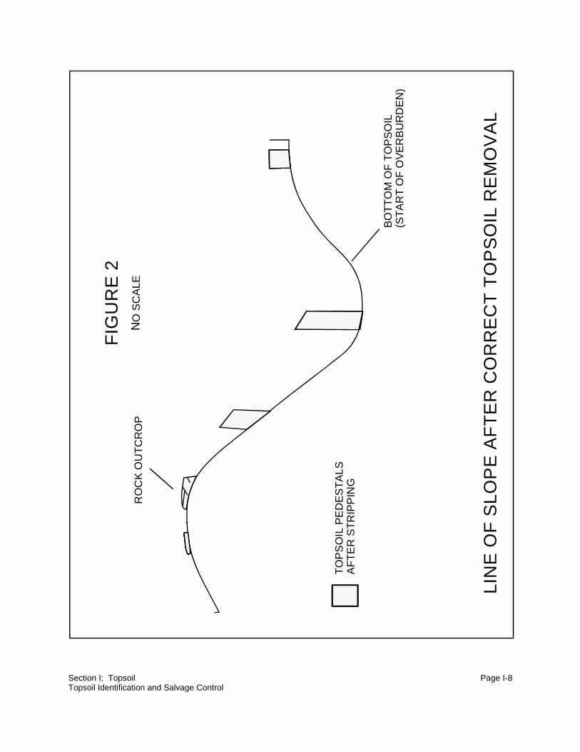
(1) Pedestals
Pedestals are the most critical references for quality control (see Figures 1 and 2).
They illustrate topsoil horizons and reference the original surface. For example,
pedestals eliminate the possibility of draw bottoms being viewed as stripped when
in fact no topsoil was stripped (see Figure 3).
(2) Ripping
Ripping the area as it is being stripped is the best way to identify topsoil, or the
completion of topsoil salvage. Ripped topsoil shows structure while ripped
overburden shows a color change from topsoil and a lack of structure.
(3) Backhoe Pits
This is an excellent method of staking topsoil depth. Backhoe pits work very well,
because one can enter the sloped pit and observe and dig at the topsoil horizons
to determine the color, texture, structure, and moisture limits as well as salt
deposition.
(4) Site Supervision
Checking the equipment operators twice a day is important for quality control.
Quality control is maintained by halting stripping operations at the bottom of the
topsoil, inspecting, and then removing any topsoil remaining in areas the operator
may have stopped stripping too soon. During the inspections you would stake
additional cuts, or indicate completion of an area. When a dependable, quality
equipment operator is stripping deep topsoil, two visits per day may not be needed.

Section I: Topsoil Page I-6Topsoil Identification and Salvage Control
(5) Instruction
Topsoil identification classes for equipment operators assure the salvage of only
topsoil. This document can be used as the class outline.
(6) Quality Contractor
If topsoil handling is contracted, an experienced, reputable contractor is important
for a good salvage operation. The foreman and key operators need some previous
experience, or at least the topsoil identification classes for a start.
(7) Augers
These can be used by a highly trained individual to stake topsoil depths, but should
not be used as a primary tool for identifying stripping depths. The auger cuttings are
difficult to interpret, as the act of cutting blends soil horizons, masking individual soil
features.

Section I: Topsoil Page I-7Topsoil Identification and Salvage Control
FIG
UR
E 1
NO
SC
ALE
TO
PO
GR
AP
HY
WIT
H T
YP
ICA
L T
OP
SO
IL D
EP
TH
S
US
UA
LLY
VE
RY
SH
ALL
OW
TO
PS
OIL
– 3
"
TO
PS
OIL
PE
DE
ST
AL
LOC
AT
ION
ST
YP
ICA
LLY
AB
OU
T 2
00' A
PA
RT
AN
D T
OP
OG
RA
PH
Y B
RE
AK
S
RO
CK
OU
TC
RO
P
UN
WE
AT
HE
RE
D O
VE
RB
UR
DE
N
HIL
LTO
P
UN
WE
AT
HE
RE
D O
VE
RB
UR
DE
N
TO
P S
OIL
2'–
3'
SM
ALL
CH
AN
NE
L
TH
E D
EP
OS
ITIO
NA
L E
NV
IRO
NM
EN
TH
AS
FO
RM
ED
BU
RIE
D D
RA
WS
.T
OP
SO
IL 5
'+ D
EE
P
Section I: Topsoil Page I-8Topsoil Identification and Salvage Control
FIG
UR
E 2
NO
SC
ALE
LIN
E O
F S
LO
PE
AF
TE
R C
OR
RE
CT
TO
PS
OIL
RE
MO
VA
L
RO
CK
OU
TC
RO
P
TO
PS
OIL
PE
DE
ST
ALS
AF
TE
R S
TR
IPP
ING
BO
TT
OM
OF
TO
PS
OIL
(ST
AR
T O
F O
VE
RB
UR
DE
N)

Section I: Topsoil Page I-9Topsoil Identification and Salvage Control
LIN
E O
F S
LO
PE
AF
TE
R I
NC
OR
EC
T T
OP
SO
IL R
EM
OV
AL
FIG
UR
E 3
NO
SC
ALE
TH
IS L
INE
SH
OW
S W
HA
TC
AN
HA
PP
EN
IN A
N A
RE
AO
F M
ED
IUM
OR
ST
EE
PR
ELI
EF
, WH
EN
PE
DE
ST
ALS
AR
E N
OT
US
ED
. OV
ER
BU
RD
EN
MA
Y B
E S
TR
IPP
ED
AS
TO
PS
OIL
,A
ND
SO
ME
SO
D A
ND
TO
PS
OIL
MA
Y B
E L
EF
T.
TO
PS
OIL
SU
RF
AC
E
TO
PS
OIL
SM
ALL
CH
AN
NE
L
PO
SS
IBLE
AF
TE
RS
TR
IPP
ING
SU
RF
AC
E
BO
TT
OM
OF
TO
PS
OIL
(ST
AR
T O
F O
VE
RB
UR
DE
N)
SO
D A
RE
A

Section I: Topsoil Page I-10
NOTES
Section I: Topsoil Page I-11Topsoil Stripping
2. Topsoil Stripping
Section editor: Laurel E. Vicklund Subsection author: Marilee G. O'Rourke
~~~~~~~~~~~~~~~~~~~~~~~~~~~~~~~~~
Situation:
Regulations require that all topsoil be removed from areas to be affected within the permit area,
and replaced for reclamation or stockpiled in the most advantageous manner.
Special Considerations:
As with all mine related activities, dust emissions resulting from topsoil activities need to be kept
to a minimum. Inadequate dust control could result in work stoppage. Access and haul roads
associated with topsoil activities should be maintained in safe operating condition.
Description of Technique:
a. Topsoil Salvage Control
(1) General
Undisturbed topsoil is off limits to all equipment and vehicles except when such
topsoil is being stripped. This will keep disturbances to a minimum and eliminate
topsoil contamination.
The area requiring topsoil removal is staked or otherwise identified. A ditch is cut
around the area to be worked each day. All topsoil hauling between the active
stripping area and the stockpile is on stripped areas only. Where possible, topsoil
removal is conducted in a manner that ensures any drainage from disturbed areas
will flow directly to sediment control structures. Ideally, topsoil removal is done only
during daylight hours.

Section I: Topsoil Page I-12Topsoil Stripping
A clear boundary delineating the native and stripped area is established and
maintained. The edge is sloped back at a 2H:1V slope angle, and a 2H:1V toe
ditch of non-topsoil material is bladed along the final topsoil edge. This ditch
provides sediment control for the area and reduces disturbance to the remaining
topsoil areas.
(2) Pedestals
Topsoil depths, previously surveyed at 200-foot intervals, are indicated on laths.
Pedestals of topsoil are left at these stakes to allow verification of the stripping
depths. These pedestals and survey control points are left in place until the project
supervisor approves removal. Upon clearance for removal, the pedestals are
salvaged as topsoil.
(3) Completion
Upon completion, all topsoil removal areas are bladed to collect any additional
topsoil not salvaged by scrapers. The entire area should be smooth-bladed for
future mining operations.
(4) Sediment Control
Sediment control needs to be addressed daily. At the end of each work day, all
disturbed areas are contained and controlled. Stripping of topsoil from the bottom
of drainages should be given first priority in order to prevent contamination of topsoil
by disturbed runoff. It may be necessary to strip drainage corridors to establish
proper drainage prior to additional topsoil removal.
b. Contractor Considerations
(1) Environmental Regulations
All levels of contractor supervisory personnel need to be aware of, and are required
to abide by, all state and federal environmental regulations that govern surface coal
mining activities. It is the responsibility of the contractor to train each contractor
employee with regard to these guidelines.

Section I: Topsoil Page I-13Topsoil Stripping
(2) Security
Access and security policies are site specific, and need to be addressed on an
individual basis. It may be advisable to require the contractor to have a supervisor
with State Mine Certification on site during all contractor working hours. The
supervisor should have the authority and responsibility to exercise the terms of the
contract on behalf of the contractor.
c. Quantities
(1) Daily Work Report
The project supervisor should inspect the working area prior to the beginning of
each shift. A daily work report, showing all load counts and hours worked for each
piece of equipment, should be completed and signed by the project supervisor.
(2) Payment Calculations
Typically, payment for topsoil removal is based on a per-cubic-yard unit rate of
material handled. The unit rate should include payment for all other incidental work,
such as haul road construction and upkeep, drainage control, ditch and berm
construction, and other ancillary activities needed to complete the job. Mobilization
and demobilization costs are usually additional to the unit rate(s).
Topsoil quantities and removal areas can also be calculated using aerial
photography or standard field survey methods.

Section I: Topsoil Page I-14
NOTES

Section I: Topsoil Page I-15Topsoil Stockpiling
3. Topsoil Stockpiling
Section editor: Laurel E. Vicklund Subsection author: Marilee G. O'Rourke
~~~~~~~~~~~~~~~~~~~~~~~~~~~~~~~~~
Situation:
Topsoil stripped from an area prior to mining is preserved for later use in a topsoil stockpile.
Regulations may require that topsoil not promptly redistributed be stockpiled in such a manner so
as to minimize wind and water erosion and unnecessary compaction.
Special Considerations:
Procedures must be followed that will prevent the loss of topsoil from the stockpile through erosion.
The establishment of a quick growing cover of vegetation on the topsoil stockpiles is advantageous
to reduce erosion and loss, and may be required by regulation. Proper construction of slopes as
well as a ditch/berm around the stockpile will also aid in erosion control and topsoil conservation.
Description of Technique:
The limits of topsoil stockpiles are field staked prior to placement of topsoil. Roads to and from
stockpiles need to be stripped of topsoil prior to use. Stockpiles must be marked with a topsoil sign
before stockpiling is begun.
Construction of a perimeter ditch/berm should precede any activities associated with material
placement in the stockpile. The topsoil stockpile is completely enclosed with this ditch/berm, which
should be approximately 1.5 feet high, or higher as needed for sediment control and topsoil
conservation. If a sediment control structure is required, the ditch/berm will need to be constructed
to ensure drainage to the structure.
Topsoil stockpile slopes should not exceed 5H:1V, to allow for seeding necessary to prevent
erosion. When stockpiling is completed, the stockpile may be scarified parallel to the contour to
minimize wind and water erosion. Large rocks uncovered during final grading activities should
be removed.

Section I: Topsoil Page I-16
NOTES

Section I: Topsoil Page I-17Topsoil Stripping Equipment
4. Topsoil Stripping Equipment
Section editor: Laurel E. Vicklund Subsection author: Frank K. Ferris
~~~~~~~~~~~~~~~~~~~~~~~~~~~~~~~~~
Situation:
There are three general equipment fleet types used to remove and/or move topsoil. These are
scrapers; loaders, trucks, and dozers; and shovels and trucks. Each fleet has unique
characteristics. Using a fleet of equipment in the wrong application will usually lead to poor quality
topsoil recovery, higher costs, and potential compliance problems.
Special Considerations:
Other than removal of topsoil from the upper portion of stockpiles, topsoil should not be stripped
at night. Color changes, which are critical in differentiating between topsoil and overburden, are not
readily evident after dark.
The stripping of frozen topsoil must be carefully evaluated. Under high moisture conditions and
deep frost, shallow topsoil can be cemented to the overburden and it is extremely difficult to strip
only the topsoil. Evaluate the site conditions and, if necessary, bypass until later.
Description of Technique:
a. Scrapers
Scrapers are the best stripping method for quality control. Scraper cuts should be no more
than 50 percent of the topsoil depth for topsoil six inches or deeper. Trying to single-pass
load topsoil that is six inches or deeper will usually include significant amounts of
overburden.
Topsoil stripping should proceed from higher to lower topographical areas; generally this
is also from shallow to deeper topsoil. In this way the scrapers are always being pushed
downhill for their best productivity, and they finish loading in an unstripped area. After the
Section I: Topsoil Page I-18Topsoil Stripping Equipment
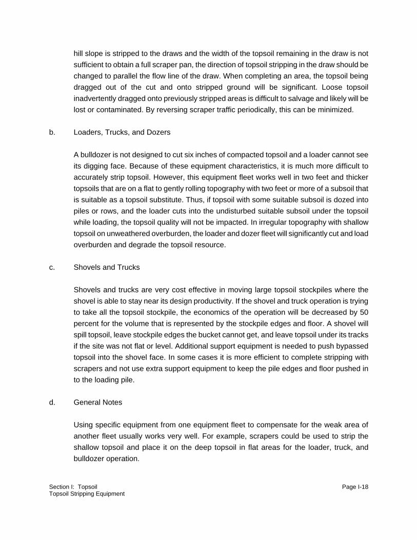
hill slope is stripped to the draws and the width of the topsoil remaining in the draw is not
sufficient to obtain a full scraper pan, the direction of topsoil stripping in the draw should be
changed to parallel the flow line of the draw. When completing an area, the topsoil being
dragged out of the cut and onto stripped ground will be significant. Loose topsoil
inadvertently dragged onto previously stripped areas is difficult to salvage and likely will be
lost or contaminated. By reversing scraper traffic periodically, this can be minimized.
b. Loaders, Trucks, and Dozers
A bulldozer is not designed to cut six inches of compacted topsoil and a loader cannot see
its digging face. Because of these equipment characteristics, it is much more difficult to
accurately strip topsoil. However, this equipment fleet works well in two feet and thicker
topsoils that are on a flat to gently rolling topography with two feet or more of a subsoil that
is suitable as a topsoil substitute. Thus, if topsoil with some suitable subsoil is dozed into
piles or rows, and the loader cuts into the undisturbed suitable subsoil under the topsoil
while loading, the topsoil quality will not be impacted. In irregular topography with shallow
topsoil on unweathered overburden, the loader and dozer fleet will significantly cut and load
overburden and degrade the topsoil resource.
c. Shovels and Trucks
Shovels and trucks are very cost effective in moving large topsoil stockpiles where the
shovel is able to stay near its design productivity. If the shovel and truck operation is trying
to take all the topsoil stockpile, the economics of the operation will be decreased by 50
percent for the volume that is represented by the stockpile edges and floor. A shovel will
spill topsoil, leave stockpile edges the bucket cannot get, and leave topsoil under its tracks
if the site was not flat or level. Additional support equipment is needed to push bypassed
topsoil into the shovel face. In some cases it is more efficient to complete stripping with
scrapers and not use extra support equipment to keep the pile edges and floor pushed in
to the loading pile.
d. General Notes
Using specific equipment from one equipment fleet to compensate for the weak area of
another fleet usually works very well. For example, scrapers could be used to strip the
shallow topsoil and place it on the deep topsoil in flat areas for the loader, truck, and
bulldozer operation.

Section I: Topsoil Page I-19Topsoil Replacement Depths
C. Replacement
1. Topsoil Replacement Depths
Section editor: Laurel E. Vicklund Subsection author: Frank K. Ferris
~~~~~~~~~~~~~~~~~~~~~~~~~~~~~~~~~
Situation:
Uniform topsoil depth replacement is generally required on reclaimed topography, however the
erosional processes of water and wind will make topsoil depths uneven. In some areas, different
topsoil depths will add to species diversity, but extensive erosion may produce very low productivity
and an area that is hard to stabilize. Erosional forces usually move topsoil to areas where it is not
needed as the depositional area collects topsoil. Varying topsoil depth in accordance with
topography will help offset these processes, and make more effective use of the topsoil resource.
Critical Consideration:
At bond release, sufficient topsoil depth is needed to provide excellent vegetative cover. A
reclaimed surface's topsoil depth varies according to how much the area is exposed to erosional
processes. Erosion can reduce the topsoil depth below the minimum needed for suitable vegetation
density in high erosional areas. If the following procedures deviate significantly from the approved
permit, approval from the regulating entity may be needed.
Description of Technique:
By placing deeper topsoil in high erosional areas and less in depositional areas, the site will be
more productive at and beyond bond release. See Figure 1. The high erosional areas would not
erode through the deep topsoil layer and cause areas of low vegetation productivity.
1. Additional topsoil should be placed at erosional points, draws, slopes, etc. because
erosional forces will decrease the depth.

Section I: Topsoil Page I-20Topsoil Replacement Depths
2. Less topsoil should be placed in depositional areas, toes of slopes and ridges, and
low gradient channels.
3. The erosional potential is based on the steepness of slopes, and the concentration
of water and wind exposure.

Section I: Topsoil Page I-21Topsoil Replacement Depths
FIG
UR
E 1
TO
PS
OIL
SE
CT
ION
OF
RE
CL
AIM
ED
GR
OU
ND
BO
VER
BU
RD
EN
A
C
D
D
E

Section I: Topsoil Page I-22Topsoil Replacement
AREA
(following
figure)
DESCRIPTION
OF
TOPOGRAPHY
SUGGESTED
TOPSOIL
PLACEMENT RANGE
COMMENTS
(see cross section for additional detail)
A Major channel
bottom
Zero Major channels are usually wet,
depositional, have a shallow gradient, and
support extensive vegetation.
B Grain/hay field 85 to 100 percent Depth may vary according to postmining
land use requirements. Deep rooting crops
may require deeper soil.
C Toe of slope 35 to 60 percent Toe of slope areas need to have a
maximum slope of 7H:IV and should be
about 300 feet wide. This thinned area may
be from 100 to 600 feet wide, depending on
the length of transition from slope to field
and the size of the slope above the area.
D Hill slopes and
tops
150 percent Through wind and water erosion, topsoil will
be moved from this area, therefore the 150
percent of average topsoil depth. On a more
complex hill topography, there could be
multiple areas of erosion and deposition.
E Steep gradient
draws
200 percent minimum Draws and drainage channels coming off of
hilly areas usually have a steeper gradient
than would be ideal. This steeper gradient
will likely cause some erosion in the
channel. To be sure the topsoil in the
channel is not completely eroded away,
additional topsoil is suggested to ensure
vegetative establishment. In areas where
erosion has broken through the topsoil, it is
more difficult to establish adequate
vegetation.

Section I: Topsoil Page I-23Topsoil Replacement
2. Topsoil Replacement
Section editor: Laurel E. Vicklund Subsection author: Marilee G. O'Rourke
~~~~~~~~~~~~~~~~~~~~~~~~~~~~~~~~~
Situation:
The replacement of topsoil after mining marks the beginning of reclamation in a given area. The
careful planning and supervision of the environmental engineer, as well as the skill of the
equipment operators, will ensure this foundation is properly laid.
Special Considerations:
As with all mine related activities, dust emissions resulting from topsoil activities need to be kept
to a minimum. Inadequate dust control could result in work stoppage. Access and haul roads
associated with topsoil activities should be maintained in safe operating condition.
Description of Technique:
a. General
Prior to topsoil replacement, confirmation of approved final grade and samples for analyses
of the top four feet of soil should be obtained. The replacement area is then delineated and
scarified parallel to the contour at an approximate depth of one foot on 18-inch intervals.
Rock piles are typically constructed within the redistribution areas prior to topsoil placement.
Topsoil is tapered into the edges of the rock piles during replacement. Rocks unearthed
during scarification are either pushed together to form small piles or added to existing rock
piles.
Sediment control needs to be addressed daily. At the end of each work day all replacement
areas are contained and controlled.

Section I: Topsoil Page I-24Topsoil Replacement
(1) Equipment Traffic
Equipment operation on topsoil areas is limited to the extent necessary to perform
removal of the stockpiled topsoil and redistribution on regraded areas. Equipment
traffic routes are not allowed on topsoiled areas. Ideally, topsoil redistribution should
only be done during daylight hours.
(2) Replacement Depths
A uniform depth of topsoil is placed on the loosened regraded surface. The desired
thickness is contingent on the specific operating plans. Topsoil thickness can be
increased in localized areas to produce micro-contours. Redistributed topsoil is
blended in with previously reclaimed areas or native edges where applicable.
Guidance stakes on a maximum of 100-foot centers provide verification of the
topsoil redistribution depths while maintaining existing contours.
(3) Final Touches
Following topsoil redistribution, the area should be bladed and inspected to ensure
adequate drainage. The area should be scarified to a depth of approximately one
foot at 18-inch intervals. To minimize erosion problems, scarification is performed
parallel to the contour. The topsoil redistribution edges are bladed to form 2H:1V
slopes. A perimeter ditch/berm, constructed of overburden material, is built around
the outer edge of the area for sediment control and topsoil conservation. Edges of
redistribution areas should be straight and have a smooth appearance.
(4) Remaining Stockpile
Partially used stockpiles are recontoured with slopes no steeper than 5H:1V. The
exposed area of the stockpile is scarified parallel to the contour to minimize erosion.
A ditch/berm approximately 1.5 feet or higher as needed for sediment control and
topsoil conservation, is reestablished.

Section I: Topsoil Page I-25Topsoil Replacement
b. Contractor Considerations
(1) Environmental Regulations
All levels of contractor supervisory personnel need to be aware of, and are required
to abide by, all state and federal environmental regulations that govern surface coal
mining activities. It is the responsibility of the contractor to train each contractor
employee with regard to these guidelines.
(2) Security
Access and security policies are site specific and need to be addressed on an
individual basis. It may be advisable to require the contractor to have a supervisor
with State Mine Certification on site during all contractor working hours. The
supervisor should have the authority and responsibility to exercise the terms of the
contract on behalf of the contractor.
(3) Daily Work Report
The project supervisor should inspect the working area prior to the beginning of
each shift. A daily work report, showing all load counts and hours worked for each
piece of equipment, should be completed and signed by the project supervisor.
(4) Payment Calculations
Typically, payment for topsoil redistribution is based on a per-cubic-yard unit rate
of material handled. The unit rate should include payment for all other incidental
work, such as haul road construction and upkeep, drainage control, regraded area
scarification, topsoil scarification, ditch and berm construction, and other ancillary
activities needed to complete the job. Mobilization and demobilization costs are
usually additional to the unit rate(s). Topsoil quantities and redistribution areas can
also be calculated using aerial photography or standard field survey methods. An
average depth of topsoil replaced for a specific area is also calculated.

Section I: Topsoil Page I-26
NOTES
Section I: Topsoil Page I-27Elevation Control
3. Elevation Control
Section editor: Laurel E. Vicklund Subsection author: Frank K. Ferris
~~~~~~~~~~~~~~~~~~~~~~~~~~~~~~~~~
Situation:
Depth control is needed to attain the desired topsoil replacement depth for optimum reclamation
success.
Special Considerations:
Control of topsoil replacement depth is difficult, because the reference point is continually being
covered with topsoil.
Description of Technique:
a. Staking
Staking with four-foot lath seems to be the best method of controlling topsoil replacement
depth. Important points for staking are spacing, location, marking, and proofing.
(1) Spacing
Spacing needs to be frequent enough to prevent shallow areas in between the
stakes. The rows should be spaced three to four scraper widths apart. Rows can
be approximately 35 to 40 feet apart, with stakes at 40 to 80 foot intervals (see
Figure 1). The interval will be determined by the equipment operator experience.
(2) Location
Location of stakes should be in a basic grid pattern, with extra stakes at topography
breaks. These stakes at topography breaks are the most important (see Figure 1).

Section I: Topsoil Page I-28Elevation Control
NO SCALE
FIGURE 1
PROFILENO SCALE
NO SCALE
A A
BP
BP
40' TO 50'
50' TO 80'
PLAN VIEW
A A
BREAK POINTBP
BP
BPBP
BP
BP
BP

Section I: Topsoil Page I-29Elevation Control
(3) Marking
Stake marking can be done by painting the length to be covered, the length to be
left uncovered, or simply marking the final fill line. Any of these methods seem to
work well as long as both sides of the stake are marked. About a two-inch overfill
is usually needed to account for compaction and settling.
(4) Proofing
Depth proofing is a good quality control check, and an absolute necessity when
payment is based on fill depth. Backhoe pits provide the best verification because
they clearly illustrate the topsoil/subsoil interface.

Section I: Topsoil Page I-30
NOTES

Section I: Topsoil Page I-31Preserving Seedbed Viability Through Direct Haul of Frozen Topsoil
4. Preserving Seedbed Viability Through
Direct Haul of Frozen Topsoil
Section editor: Laurel E. Vicklund Subsection author: Kenneth L. Wrede
~~~~~~~~~~~~~~~~~~~~~~~~~~~~~~~~~
Situation:
In the summer of 1987, reclamation personnel at the Wyodak Mine near Gillette, Wyoming
observed that a small parcel of regraded spoil, which had received "live" frozen topsoil during a
stripping operation the previous winter, was producing noticeable stands of native grasses and
shrubs. "Live" topsoil is material which is hauled directly from the stripping area to the replacement
area. It was also noted that the density of undesirable plant species of an opportunistic nature was
lower when compared to adjacent areas conventionally seeded.
While a formal study was never conducted, it is visibly evident even today that the parcel of land
has better diversity and density of native species than that of adjacent lands. It is also thought,
though never weighed against the operational difficulties nor calculated, that hauling "live" frozen
topsoil may reduce the cost of final revegetation.
Special Considerations:
While the practice of hauling frozen topsoil is not one which operational personnel would savor,
there is reason to believe that several long-term benefits could be achieved using this method.
Ideally, the direct haul of frozen topsoil would:
1. Propagate heartier stands of native grasses and shrubs.
2. Reduce plant stress by moving them while they are in a dormant state.
3. Reduce the amount of interseeding needed in some reclamation operations.
4. Speed the succession of native species on reclaimed lands.
5. Lower seed costs.
While making a standard practice of moving topsoil in the dead of winter usually is not thought to
be an ideal reclamation practice, these results indicate occasional use of the practice might have
Section I: Topsoil Page I-32Preserving Seedbed Viability Through Direct Haul of Frozen Topsoil
benefits in special situations. A mosaic of mature native grasses, distributed among areas seeded
by conventional means, would provide a seed source for adjoining lands, and mature shrubs would
tend to spread to areas outside of the mosaic.
Description of Technique:
During the winter of 1986/1987, an area of approximately 16 acres in and near the floodplain of the
restored Donkey Creek channel received "live" frozen topsoil during a direct haul stripping
operation. A dozer/scraper fleet was used for this operation. Replacement depth was approximately
1.88 feet. Efforts were made to selectively handle the top six inches of frozen topsoil, and "cap"
topsoil previously laid. It was hoped that this "seed bank" approach might encourage quicker
reestablishment of native species and cover. (Wyodak Mine Annual Report, 1987)
Spring and fall plantings were not conducted in the area during 1987, but were delayed until the
following year. In spite of this, substantial stands of intermediate, western and bluebunch
wheatgrass appeared during the spring and summer of 1987, along with two predominant shrub
species, rubber rabbitbrush and silver sagebrush. It is also theorized that native plant species in
this area benefitted from the infiltration of additional moisture during the spring runoff, as the area
was not bladed following topsoil placement.
Operational difficulties were encountered as could be expected with any wintertime stripping
operation involving scrapers. Rough conditions, common in the cut and fill areas, reduced cycle
times. "Live" topsoil was many times placed beneath "B" and "C" horizon material in the reclaimed
area due to logistical difficulties. Although it turned out to have a positive effect as was previously
mentioned, final grading could not be done effectively because the massive blocks of frozen topsoil
were nearly impossible to fine blade.
Another fear was that seeds of undesirable weed species would be caught in the void spaces left
in the ungraded topsoil, germinate, and compete with native plant species. The opposite has in fact
proven true, as the area was nearly free of kochia weed during the first growing season and has
not experienced the encroachment of undesirable weed species.

Section I: Topsoil Page I-33References
D. References
Wyodak Mine. November 30, 1987. Annual Report, submitted to the Wyoming Department
of Environmental Quality - Land Quality Division. p. 10.

Section I: Topsoil Page I-34
NOTES
SECTION IISECTION II
HYDROLOGYHYDROLOGY
Section Editor: Frank K. FerrisSection Editor: Frank K. Ferris
table of contentstable of contents

Section II: Hydrology Page II-ii
TABLE OF CONTENTS
SECTION II: HYDROLOGY
A. Introduction . . . . . . . . . . . . . . . . . . . . . . . . . . . . . . . . . . . . . . . . . . . . . . . . . . . . . II-1
B. Control Structures . . . . . . . . . . . . . . . . . . . . . . . . . . . . . . . . . . . . . . . . . . . . . . . . II-3
1. Sediment Control Basin Design and Construction . . . . . . . . . . . . . . . . . . . . II-3
2. Diversion Design and Construction . . . . . . . . . . . . . . . . . . . . . . . . . . . . . . . II-13
3. Drop Structures . . . . . . . . . . . . . . . . . . . . . . . . . . . . . . . . . . . . . . . . . . . . . . II-21
4. Backfill Impoundments . . . . . . . . . . . . . . . . . . . . . . . . . . . . . . . . . . . . . . . . II-34
C. Alternative Sediment Control . . . . . . . . . . . . . . . . . . . . . . . . . . . . . . . . . . . . . . . . II-46
1. Straw or Hay Bale Check Dams . . . . . . . . . . . . . . . . . . . . . . . . . . . . . . . . . II-46
2. Rock Check Dams . . . . . . . . . . . . . . . . . . . . . . . . . . . . . . . . . . . . . . . . . . . II-50
3. Sediment Fence . . . . . . . . . . . . . . . . . . . . . . . . . . . . . . . . . . . . . . . . . . . . . II-54
4. Gabion Baskets . . . . . . . . . . . . . . . . . . . . . . . . . . . . . . . . . . . . . . . . . . . . . . II-60
5. Vegetative Filters . . . . . . . . . . . . . . . . . . . . . . . . . . . . . . . . . . . . . . . . . . . . II-66
D. Reconstruction of Hydrologic Features . . . . . . . . . . . . . . . . . . . . . . . . . . . . . . . . II-68
1. Small Drainage Waterway Construction . . . . . . . . . . . . . . . . . . . . . . . . . . . II-68
2. Stream Channel Construction . . . . . . . . . . . . . . . . . . . . . . . . . . . . . . . . . . . II-76
3. Wetlands Reconstruction . . . . . . . . . . . . . . . . . . . . . . . . . . . . . . . . . . . . . . II-83
4. Special Considerations in Planning and Constructing
Permanent Postmining Impoundments . . . . . . . . . . . . . . . . . . . . . . . . II-93
E. Hydrologic Control Structure Tolerances . . . . . . . . . . . . . . . . . . . . . . . . . . . . . . II-102
F. Surface Water Monitoring Using a Weir . . . . . . . . . . . . . . . . . . . . . . . . . . . . . . II-112
G. References . . . . . . . . . . . . . . . . . . . . . . . . . . . . . . . . . . . . . . . . . . . . . . . . . . . . II-115
H. Citations . . . . . . . . . . . . . . . . . . . . . . . . . . . . . . . . . . . . . . . . . . . . . . . . . . . . . II-118

Section II: Hydrology Page II-iii
NOTES

Section II: Hydrology Page II-1Introduction
A. Introduction
Section editor: Frank K. Ferris
~~~~~~~~~~~~~~~~~~~~~~~~~~~~~~~~~
Control of water and sediment is important in disturbed areas. One of the most important post-
disturbance features is the reconstruction of drainages. These hydrologic features control erosion
and restore the surface hydrologic function.
The hydrology techniques in this section cover some common water control structures, sediment
control, and reconstructed drainages that have been implemented at various mine locations. Feel
free to contact the respective author(s) if you have any questions regarding any of the methods
described. The following aspects should be considered when implementing any design:
1. Proper installation is critical to the success of any project. In hydrology, it is
extremely critical because once water has bypassed or undermined your structure,
structural failure is likely.
2. If the problem or project is too complicated or too large, get experienced help. It is
not unusual for an inexperienced person to have several failures prior to solving a
hydrology problem.
3. Match the method to the site condition. For example, hay bales may not be
effective in a steep draw.
4. Match the method to the climate. For example, a grass filter is less likely to be
successful in an arid environment.
There has been an important development regarding a self-functioning sediment reservoir. The
reservoir operates without pumping, sampling, or logistical activities in muddy conditions. It will
function in all weather at all times of the day and night. This sediment reservoir type discharges the
water through a sand filter, which is part of the embankment. The only annual maintenance
required is the removal of sediment from the reservoir side of the sand filter. If built according to
appropriate designs, the discharge will be cleaner than required. Because the water, which is
discharged through the sand filter, is in compliance with suspended solids requirements, sampling
is not required.

Section II: Hydrology Page II-2Introduction
The passive sand filter sediment reservoirs have been approved by the Ohio and Pennsylvania
Solid Waste agencies, and have been in use for several years. A mine in Kentucky is also
constructing one during 1996. This design is a winning situation for industry and regulating
agencies alike. Since only clean water is discharged by the sand filter, no out-of-compliance
suspended solids discharges can occur.

Section II: Hydrology Page II-3Sediment Control Basin Design and Construction
B. Control Structures
1. Sediment Control Basin Design and Construction
Section editor: Frank K. Ferris Subsection author: Richard C. Warner
~~~~~~~~~~~~~~~~~~~~~~~~~~~~~~~~~
Situation:
Sediment control basins have been used extensively for storm water management and sediment
control throughout the mining industry. A variety of dam/impoundment types have been utilized
which include excavated basins, embankment dams, and, more recently, infiltration basins.
Sediment basins are used to reduce peak flow, trap sediment, and meet effluent limits.
This subsection will address the design and construction components of storm water and sediment
control basins. Since construction procedures are readily available (SCS National Engineering
Handbook, Section 19 (SCS, 1985); Earth Manual, Department of the Interior (Bureau of
Reclamation, 1974); and SCS Engineering Field Manual (SCS, 1984)) emphasis will be placed on
design considerations that can enhance basin performance in a cost effective manner.
Special Considerations:
The current effluent limit, which is widely used in the mining industry, is 0.5 milliliters per liter
settleable solids at peak discharge. The Imhoff cone test is used to determine the settleable solids
concentration at the discharge point from a sediment basin. In addition to meeting the required
effluent concentration, basins are used to minimize the hydrologic impact of mining by reducing the
peak flow, often to pre-mining conditions. National Pollutant Discharge Elimination System
(NPDES) regulations, which may be applicable under certain situations, normally require effluent
limits for Total Suspended Solids (TSS), usually specified in milligrams per liter. To meet such
regulations additional design measures are frequently needed. Regulations focus on specific
criteria, often neglecting the aspects that influence the fluvial system. The sediment discharge
frequency/duration/concentration relationship influences aquatic invertebrates and multiple use of
the receiving waters. Regional difference, such as the background concentration of sediment in the
receiving stream, are also ignored. The implications of a single, nationwide standard, that
disregards the flow and sediment regime of the fluvial system, discourages the development of

Section II: Hydrology Page II-4Sediment Control Basin Design and Construction
procedures and methods that have a holistic approach, thereby reducing the incentive to explore
more environmentally sound and cost effective approaches.
Description of Technique:
a. Design Considerations
Sediment basins are used to reduce peak flow, trap sediment, and meet effluent
concentrations. The efficiency of basins to accomplish these functions is directly related to
basin design and construction procedures. Additionally, the efficiency of a basin is highly
influenced by up-gradient mining activities and control measures. Basin efficiency is also
directly influenced by the incoming eroded sediment size distribution. If up-gradient controls
such as check dams, sediment traps, furrows, terraces, etc. are used, the sand fraction of
the transported sediment is reduced. Although the overall trap efficiency of the basin will
subsequently be decreased by these measures, the need to provide additional sediment
storage and/or expensive sediment removal is also reduced.
Basin design should be performed on a regional basis such that runoff, sediment
concentration and amount, and eroded sediment particle size distribution information can
be incorporated into the design. Also, if regulations change and provide for consideration
of the fluvial system of the receiving stream, regional considerations will be even more
important to incorporate in basin design measures.
Basin design considerations include: location, gradient, and stabilization of the inflow
channel; length-to-width ratio of the pool measured at the crest of the principal spillway;
basin shape and depth; sediment storage capacity; permanent pool storage; location, type,
and size of the spillways; passive and active dewatering provisions; use of internal check
dams, turbidity curtains, and baffles; and use of flocculation additives. As can be seen from
this list of engineering and design considerations, the performance of a basin in reducing
the peak flow, capturing sediment, and meeting effluent concentration limits is directly
achieved through design and construction rigor.
(1) Inflow Channel
Inlet(s) should be located to provide the hydraulically longest flow path between the
inlet and outlet. This will help to reduce short circuiting and provide a higher

Section II: Hydrology Page II-5Sediment Control Basin Design and Construction
potential for mixing the inflow with the permanent pool, thereby reducing the
sediment concentration through dilution and providing a longer residence time
needed for settling sediment. The basin inlet should be a channel versus a pipe to
reduce concentrated flow and avoid clogging by debris during large storm events.
The inlet should be stabilized by geotextiles, rock riprap, or the other means
described in the subsection entitled "Drop Structures" in this section of the
handbook. The inlet channel width should be wide to further enhance mixing.
(2) Length to Width Ratio
The length-to-width ratio of the basin should attempt to approach two to one. This
ratio was found to reduce dead storage and short circuiting. A ratio of one to one
was found to increase dead storage from approximately 20 to 30 percent. Longer
length-to-width ratios have not been adequately investigated but should marginally
decrease dead storage and marginally increase trap efficiency.
(3) Basin Shape and Depth
The shape and depth of the basin should provide a storage depth that reduces
resuspension of previously settled sediment. An alluvial depositional fan is seen at
the entrance of many sediment basins. This depositional feature reflects the
settling characteristics of incoming sediments. A deeper basin will reduce the
potential resuspension of deposited sediment. Thus a tradeoff exists between
length and depth with the two to one ratio providing the length needed for settling
time and the deeper pond reducing potential sediment resuspension. The difficulty
in assessing this trade-off is due to the complicating factor that the deeper pool
will allow settling particles to remaining in suspension for a longer period prior to
reaching the level of previously settled sediment. Thus, sediment in the deeper
pond may be discharged while still in suspension. Field experience indicates that,
for a pond with a permanent pool, a length-to-width ratio of two to one is
adequate. Two to three feet of permanent pool above the sediment storage area
provides a buffer to reduce sediment resuspension and facilitates the tradeoff
between sediment settling depth and the potential for resuspension. Further
research is needed.

Section II: Hydrology Page II-6Sediment Control Basin Design and Construction
(4) Sediment Storage Capacity
Sediment storage is often sized by a rule-of-thumb such as "X" acre-feet of
storage per disturbed contributing watershed acreage. Such simple methods often
yield an overdesign of the actual needed sediment storage capacity. Rule-of-thumb
methods often have no confirmed data base nor do they reflect the erosional and
sedimentary processes occurring within the watershed. There are numerous
opportunities to contain sediment within the watershed. A significant portion of
water enters the active pit area either as precipitation or runoff directed to the pit.
The judicious use of check dams, sediment traps, furrows, terraces, and numerous
other onsite control techniques reduces the need for excessive sediment storage.
An alternative method to the rule-of-thumb approach is to estimate the sediment
load associated with the 10-year 24-hour design storm event and normalize for
average annual sediment yield based on the published annual R-factor. Refer to
the Sediment, Erosion, Discharge by Computer Aided Design (SEDCAD+)
Manual, Version 3 (Warner and Schwab, 1992) for further information regarding
this method. Another approach is to simply specify the sediment clean out level
based on past experience and basin performance in the region. Other methods
include estimation using the Soil Conservation Service's universal soil loss
equation or its modifications.
(5) Permanent Pool Storage
The size of a permanent pool affects peak flow reduction, sediment trap efficiency
and effluent concentration. The primary consideration is how the permanent pool
affects the detention time of incoming flow and sediment. The advantage of a
permanent pool is that, assuming the water in the basin is clear at the start of a
runoff event, it will provide significant dilution, thus reducing the concentration of
the effluent. The negative aspect of a permanent pool is that there is usually less
space available for detention of the incoming waters (inflow hydrograph), and runoff
will be discharged at a faster rate. Additionally, the depth that a sediment particle
must traverse to be deposited is increased; thus increasing peak flow, decreasing
detention time, and retaining a greater percentage of sediment particles in
suspension. If a permanent pool and a partially dewatered basin system are
contrasted, these trade-offs can be readily visualized. The partially dewatered basin
has initially less water for dilution of the incoming flow but greater capacity to retain
a portion of the inflow hydrograph. Additionally, sediment entering the dewatered
Section II: Hydrology Page II-7Sediment Control Basin Design and Construction
system will have an initially smaller settling distance and a greater detention time
than one entering the permanent pool basin. Refer to the SEDCAD+ Training
Manual (Warner and Schwab, 1992) for a more complete discussion and illustration
of the efficiency of a passive dewatering system. It appears that the trade-off
among all of these design parameters results in the conclusion that dewatering
basins provide a higher detention time, greater sediment trap efficiency, a lower
peak discharge, a lower peak stage, a smaller basin, reduced embankment height,
and lower effluent concentration with respect to settleable solids than the
permanent pool situation.
(6) Spillway
Spillway location, type, and size directly influence the performance of sediment
basins. A single spillway provides no significant attenuation of the incoming storm.
Thus, peak flow will only be slightly reduced, detention time will be minimal,
potential sediment trap efficiency will be reduced, and effluent concentration will be
higher than alternative spillway techniques. A spillway sized to rapidly discharge the
inflow hydrograph will likewise have similar deficiencies.
(7) Dewatering Provisions
The previous discussion of the tradeoffs between a permanent pool and a partially
dewatered basin emphasize the potential increased efficiency of a partially
dewatered basin. Methods to achieve dewatering are: (1) perforated risers, (2)
perforated risers with tapered holes, (3) perforated risers with rock filters, (4)
perforated risers with geotextile filters, (5) trickle tube, (6) slow sand filter, (7) fixed
siphon, and (8) floating siphon. Methods 1 through 6 can be passive or made active
with the use of a discharge valve. Methods 7 and 8 are normally operated passively
but can be operated actively with the use of a pump. A perforated riser has a higher
trap efficiency than the standard drop-inlet principal spillway. Use of tapered holes
in a perforated riser facilitates various operational dewatering schemes used to
provide storm water storage by varying incremental dewatering times. The addition
of a rock filter, for all or part of the height of the perforated riser, increases
sediment trap efficiency and reduces effluent concentration. The filtering action of
the geotextile further reduces effluent concentration but significantly increases
dewatering time. This increase in dewatering time can be partially overcome by
only using the geotextile for the lower perforations. Locating a small trickle tube

Section II: Hydrology Page II-8Sediment Control Basin Design and Construction
near the sediment storage volume functions like a single dewatering orifice in a
perforated riser but has the disadvantage of releasing sediment deeper in the pond.
A fixed siphon tube has similar disadvantages but should reduce sediment
concentration due to the forced upward discharge during the siphoning period. The
floating siphon tube has the added advantage of always discharging slightly below
the surface where sediment concentration is low. Slow sand filters have been
installed in Pennsylvania and Ohio to dewater basins at landfills. The effluent
concentration is lower than for any other dewatering method observed to date.
Research is currently ongoing to mathematically model the sediment removal
effectiveness of slow sand filters and will be incorporated into SEDCAD+ version 5.
Passive systems function automatically, which is an advantage for remote locations
and reduces work load. The advantage of placing a valve on the discharge line of
these dewatering systems is to utilize contained water for fugitive dust control or
other mining uses and to discharge lower sediment concentration after a longer
settling time has elapsed.
(8) Check Dams, Turbidity Curtains, and Baffles
Internal check dams are provided to accomplish numerous functions: (1) provide
a chamber for sediment storage of the larger size sediments, (2) facilitate sediment
clean out, (3) provide detention and slow release through previously deposited
sediments for small storms, and (4) distribute runoff more uniformly throughout the
width of the basin to reduce potential short circuiting and dead storage. The internal
check dam should have a rock trench drain beneath it to facilitate dewatering of the
first chamber to the second chamber of the sediment basin. For high flows that
completely fill both chambers, the internal check dam may exacerbate trap
efficiency by actually creating a short circuiting of the inflow by raising the
sediment-laden water over the internal check dam to a higher elevation. Further
research is needed. Turbidity curtains function to lengthen the flow path between
the inlet and outlet. The turbidity curtain should direct flow beneath and to the sides
of the curtain. These curtains should be relatively porous such that some flow can
also be transported through the curtain.

Section II: Hydrology Page II-9Sediment Control Basin Design and Construction
(9) Flocculants
Flocculants can further increase the effectiveness of sediment basins and may,
when used with dewatering techniques, further reduce basin size. Flocculants are
predominantly being used in Texas and western Canada to achieve higher trap
efficiencies and lower effluent sediment concentrations.
b. Construction Considerations
Several construction elements are discussed in the subsections entitled "Special
Considerations in Planning and Constructing Permanent Postmining Impoundments" and
"Hydrologic Control Structure Tolerances" in this section of the handbook. This subsection
will focus primarily on construction quality control during the compaction process, but will
address other facets of construction such as clearing and grubbing, excavating the cutoff
trench, and constructing the emergency spillway. Large dam construction is considered
beyond the scope of this section and will not be discussed.
(1) Soils
Borings, or at least test pits, should be made throughout the pond area with
particular attention paid to the location of the embankment. Soils suitability depends
on the ability of the soils to be compacted, thus developing a relatively impervious
basin base and embankment. Silty clay loams and sandy clay loams are excellent
potential soils for pond and embankment construction.
The purpose of foundation studies is to assure that a stable support of the
embankment will be provided during saturated conditions and that necessary
elements exist to prevent excessive seepage through the key way. Clearing and
grubbing is necessary to remove vegetation, soils with root growth, and soils that
are unsuitable for construction. Cutoff trench excavation is an extension of the
clearing and grubbing operation. The cutoff trench functions to reduce seepage
beneath the embankment. Its width should be that of a dozer or compactor to
facilitate operations.
Prior to compaction, standard soil tests need to be conducted primarily to
determine the density-moisture content relationship. Scarifying the foundation soils
will help bond the compacted lift to the foundation. Additionally, scarification

Section II: Hydrology Page II-10Sediment Control Basin Design and Construction
between lifts will also reduce the overall permeability of the soil layers. Lift
thickness should relate to the construction equipment. If only a dozer is used, a lift
thickness of four to six inches will be provide minimal compaction effort. The use
of a compactor and six inch lifts will increase compactive effectiveness and ensure
a better basin and embankment.
(2) Construction Quality Control
The key elements for construction quality control are scarification of the previous
lift, lift thickness control, soil lift mixing and blending, and, most importantly, proper
control of the compacted moisture content. The Proctor test, in conjunction with a
permeability test, will provide information necessary for proper compaction needed
to assure a low permeability soil liner and embankment. A range of moisture
contents and densities needed to provide an acceptable permeability will emerge
from these tests. It has been found that providing air-tight bags containing soils at
moisture contents below, at, and above the target moisture content readily assist
operators in recognizing the correct soil conditions during the construction phase.
Furthermore, equipment operation provides an immediate feedback regarding
proper moisture content during construction. A properly trained compactor operator
can readily determine by the "feel" of the equipment and observation of the
equipment foot print if sufficient moisture content exists and needed compaction
has been achieved. The compactor should "walk out" after four to seven passes in
a properly compacted soil.
All of this compaction testing may not be necessary for every embankment. An
adequately compacted embankment and pond surface may be achieved given
proper soils, a relatively close moisture content, and passage of construction
equipment over the embankment such that the equipment effectively compacts the
entire width of the embankment. The level of needed compaction dictates the
degree of construction quality control that is necessary for a given operation.
(3) Emergency Spillway
The emergency spillway should use the original ground if practical, otherwise
excavation of the inlet channel and exit channel will be required. The emergency
spillway should be constructed such that no flow will be conveyed against the
embankment. If this is not practical then rock riprap, with a bedding stone blanket

Section II: Hydrology Page II-11Sediment Control Basin Design and Construction
and/or geotextile, should be used for protection of the embankment. Spillway
dimensions should be selected to convey the design discharge. As a practical
consideration, it is advisable to over-design the emergency to convey the 100 year
or larger design storm. The cost of this over design is minor with respect to the
safeguards that it provides. A rule-of-thumb used by the Soil Conservation Service
(SCS) is that the maximum width of the bottom of the emergency spillway should
not exceed 35 times the design depth of flow. This is to preclude potential
accumulation of deposited material and debris and to reduce the potential for
establishing meandering flow through the spillway.

Section II: Hydrology Page II-12
NOTES

Section II: Hydrology Page II-13Diversion Design and Construction
2. Diversion Design and Construction
Section editor: Frank K. Ferris Subsection author: Richard C. Warner
~~~~~~~~~~~~~~~~~~~~~~~~~~~~~~~~~
Situation:
Diversions are used throughout mining to intercept and convey runoff. Some diversions used to
convey runoff from non-disturbed areas around active mining sites preclude commingling of runoff
waters and reduce the quantity of runoff to subsequently be controlled by sediment basins.
Diversions take on many design forms depending upon the quantity of runoff and slope of the
channel. Classically, as the quantity of runoff increases, there is a progression from bare earthen
to grassed waterways to rock riprap channels.
Numerous commercial products can be used to stabilize diversions. Lower flow velocities can be
controlled by excelsior mats and geotextiles. As flow increases, grouts, gabions, and concrete filled
fabric forms can be used. If properly designed and constructed, diversions perform the duel
functions of conveying runoff and remaining stable, i.e. non-erosive. Poor construction techniques
and inadequate time for stabilization prior to a significant discharge event can cause temporary
failure of the diversion and create recurring cost.
Special Considerations:
In the design of diversions, the development of a stable channel for a rather large design storm
appears to be the primary consideration. Often diversions can accommodate the large storm
event, but failure to consider potential sediment deposition from intermediate events, and
subsequent loss of conveyance capacity, sometimes leads to failure of the control structure. In the
case of terraces, the failure of an up-gradient terrace causes the failure of all down-gradient
terraces. Diversion failures can occur due to construction procedures that do not adequately
provide the needed measure of construction quality control. An aggressive field inspection of the
diversion during construction can reduce the propensity of potential failures by assuring that proper
slope, depth, freeboard, and channel transitions have been established. Failure to give adequate
attention to a stone blanket and/or a geotextile during the placement of rock riprap creates the
potential for undercutting beneath the rock layer, erosion and transport of sediment, and ultimately
failure of the control structure to function properly. Inadequate design information exists for steep
Section II: Hydrology Page II-14Diversion Design and Construction
slope rock riprap design, i.e. slope greater than 15 percent. The placement and distribution of rock
riprap (Dmax, D50, and D10) along the rock riprap diversion also creates less than adequate
construction conditions.
Description of Technique:
a. Design Considerations
Methods will be outlined in this subsection and reference will be made to standard
practices. Discussions will center around how to avoid failures and the expense of diversion
reconstruction. Since the design of terraces for surface mining has not been adequately
addressed in literature, design considerations will also be outlined for terraces. Additionally,
techniques that have no real design methodology in literature, but seem to resolve potential
problems in the field, will be discussed. It is hoped that this type of informal technology
transfer can provide a vehicle of information exchange to the extent necessary for others
to try the techniques, and through gained experience improve upon the ideas.
(1) Temporary Diversions
Bare soil or spoil diversions are commonly used as temporary diversions. They are
relatively cheap to construct but often require significant maintenance. Thus, the
tradeoff between initial capital cost and maintenance cost is readily apparent. The
limited permissible velocity approach is normally used. The technique is simple.
The soil or spoil is linked with a permissible velocity. If in the actual design the
permissible velocity is not exceeded, the diversion is assumed to be stable and will
convey the discharge without significant erosion. It is a Mannings' equation solution
linked with the continuity equation. Usually many design elements are ignored. The
permissible velocities listed in literature are limited and do not readily translate to
many spoils. Thus, the initial determination of permissible velocity is not readily
apparent. The development of listed permissible velocities is largely based on
intuition and experience gained from cut channels used for irrigation that are
relatively stable. Often, both cut and fill is necessary in mining operations and the
fill soils are not properly compacted to withstand the permissible velocities. The
affect of a design near the critical slope is often ignored. Uniform flow at or near the
critical depth is unstable. A slight irregularity in the construction or deposition in a
reach of the diversion can cause a shift in the Mannings' "n", thereby developing
an unstable condition. Uniform flow at or near the critical depth is observed to
Section II: Hydrology Page II-15Diversion Design and Construction
create a sort of standing wave which can cause an appreciable change in flow
depth and in some circumstances, exceed the diversion capacity. Earthen channels
often meander, causing erosion and deposition. Where sediment deposit occurs
along channel reaches overflow conditions can exist.
(2) Diversion Stability
(a) Rock Check Dams
Besides these design conditions, it should be realized that for many soils
and storm conditions for various regions, runoff from a very limited acreage
can be controlled by earthen diversions. All of this appears to be bad news.
How can earthen diversions be salvaged? Promising techniques use check
dams made of durable rock. This is illustrated in Figures 1, 2, and 3.
The check dam creates a back flow condition, thereby reducing transport
velocity and creating a depositional opportunity for transported sediment.
Thus, the potentially erodible channel is transformed to a stable channel.
The design of this channel should take into account the needed additional
conveyance capacity, assuming that deposition removes a portion of the
channel cross sectional area. The check dams are designed as broad
crested weirs, or sharp crested weirs for the geotextile check dam. The
dams are the flow constriction within the channel. Since the erodible nature
of the problem has been eliminated, these check dam stabilized channels
can now accommodate much larger drainage areas and higher peak flows
than the standard limited velocity methodology. Check dam spacing is a
function of slope. A conservative approach is to have the back water of each
dam reach the up-gradient check dam. These designs have been
successfully installed in the Piedmont area of South Carolina and in the
Mississippi Delta region, both areas which are prone to highly erodible soils.

Section II: Hydrology Page II-16Diversion Design and Construction
GA
BIO
N B
AS
KE
T D
RO
P S
TR
UC
TU
RE
PL
AN
VIE
W
FIG
UR
E 1
FLOW
SC
AL
E:
NO
NE
– U
SE
DIM
EN
SIO
NS

Section II: Hydrology Page II-17Diversion Design and Construction
4485
4483
4483
4485
4487
4489
MIR
AF
I 500
X F
AB
RIC
AT
AL
L G
AB
ION
/EA
RT
HC
ON
TAC
T S
UR
FAC
E
EX
ISTI
NG
BA
NK
SLO
PE
MA
Y S
LOP
E L
AS
T B
AS
KE
T
EX
ISTI
NG
BA
NK
SLO
PE
MA
Y S
LOP
E L
AS
T B
AS
KE
T
SE
CT
ION
A
FIG
UR
E 2
SE
CT
ION
B

Section II: Hydrology Page II-18Diversion Design and Construction
FIG
UR
E 3
SE
CT
ION
D
SE
CT
ION
C
4483
4485
4487
4489
4484

Section II: Hydrology Page II-19Diversion Design and Construction
(b) Grassed Waterways
Grassed waterways are often used to increase diversion stability and
therefore convey larger runoff quantities. The classic design of grassed
waterways is based on retardance classifications which enable the design
for conveyance, under long grass conditions, and stability, under short grass
conditions. To perform satisfactorily, grassed waterways are dependent
upon climatic conditions that are favorable to vegetative establishment and
growth.
To successfully establish grassed diversions, many options exist but few are
actually employed. The channel can be stabilized by: small check dams as
previously described; commercially available products utilized to protect the
channel and assist vegetal establishment; construction of the diversion in
advance of actual use; use of a rock center section of a low flow channel;
or diversion of runoff during establishment. Detailed design procedures are
provided in SCS-TP-61, Handbook of Channel Design for Soil and Water
Conservation (SCS, 1947).
(c) Rock Riprap
Rock riprap diversions can convey large quantities of runoff on steeper
slope than can be considered for earthen or grassed diversions. As
previously stated, the data base for designs is based on typical stream
gradients and is limited for steeper channels. Thus, extrapolation is the
design method for diversions greater than approximately 10 percent.
Numerous methods have been developed to predict the D50 rock size. These
vary from simply solving Mannings' equation, by estimating Mannings' "n",
to methods that compare resisting moments to overturning moments and
are linked with a safety factor. Analysis has been completed for a stream
approximately 20 feet wide and of trapezoidal shape which compared eight
methods. Most of the methods predicted a D50 within +/- 3 inches. Thus for
channel slopes less than 10 percent, and for relatively small streams,
numerous methods may be comparable. It is recommended that alternative
methods be used to develop a feel for the probable D50 size and, as always,
practical experience gained from field applications that actually work is the

Section II: Hydrology Page II-20Diversion Design and Construction
most valuable design asset available. Unfortunately, the applicable range of
various methods is not explicitly documented. Durable rock that is angular
in shape should be placed by a backhoe or trackhoe to avoid segregation
of rock sizes from dumping and pushing with a dozer.
(3) Terraces
Terrace designs have been predominantly developed for agricultural endeavors.
Terraces fail in mining reclamation due to deposition of sediment within the terrace
or undercutting by flow at the soil-terrace interface, which sometimes produces a
vehicle for piping beneath the terrace. Animal bore holes also sometimes contribute
to undercutting terraces. Designs need to address both sediment and storm water.
If terraces are to function as lateral sediment traps, either by design or by practice,
then sediment deposition must be determined by erosion and transport models.
The quantity of sediment expected to be deposited should be predicted and
additional capacity provided.
The terrace slope and outlet control are predominant design parameters. The outlet
should be designed to rapidly discharge larger runoff events while storing a portion
of the runoff from these events. Smaller runoff quantities can be more easily
detained through a passively dewatered outlet. The benefit of retaining a portion
of the runoff is for establishment of vegetation. Use of small internal check dams
located along the length of the terrace can provide runoff storage and also reduce
the failure of down-gradient terraces if an up-gradient terrace fails. The SEDCAD+
version 3 program can readily assist in the design of terraces, bare earthen
diversions, grass waterways, and rock riprap channels.

Section II: Hydrology Page II-21Drop Structures
3. Drop Structures
Section editor: Frank K. Ferris Subsection authors: C. Marty Jones/Christopher D. Lidstone
~~~~~~~~~~~~~~~~~~~~~~~~~~~~~~~~~
Situation:
Drop structures are typically constructed at locations where the "design" or "as-constructed"
channel gradient is too steep, resulting in excessive flow velocities and the need for channel
protection. A drop structure can accommodate the required channel fall over a relatively short,
protected channel reach, while providing for the construction of a long section of lower gradient
unprotected channel upstream and downstream of the structure.
Drop structures can also be located at sediment pond inlets and outlets to enhance the stability
of the dam structure during flood overtopping (spillway) events, or the stability of the upstream
channel during typical runoff events. Some states and non-coal regulatory agencies allow drop
structures in the reclamation plan as a permanent structure.
Special Considerations:
Drop structures should be located in a straight channel section where the fluid forces are steady
and uniform. It is recommended that the structure be located at least 100 feet upstream or
downstream of any bends in the channel, and a minimum of 100 feet upstream or downstream of
channel confluences. Minimizing excavation, earthwork, and rock costs should be considered in
the location of the structure.
Many regulatory agencies have guidelines or requirements which dictate the design life, hence
hydrologic design event for channel protection structures. Design life may also reflect the level of
risk acceptable to the designer or owner of the facility. Peak flow estimates for such design events
are generally developed with computer models, which utilize SCS methods to predict the peak
discharge. These include the: U.S. Army Corps of Engineers, HEC-1 Flood Hydrograph Package;
QTR-55; and Sedimot.

Section II: Hydrology Page II-22Drop Structures
Description of Technique:
a. Drop Structures
There are three main types of drop structures: concrete drops, rock riprap drops, and wire
enclosed rock riprap drops (gabions). Concrete structures can be sloped chute structures
or vertical drops. Rock riprap structures are typically constructed as sloped structures, andgabions are usually constructed as stepped structures. Rock riprap structures and gabionstructures, which are more cost effective and are utilized more often than concrete dropstructures, will be discussed in this section.
(1) Rock Riprap Drop Structures
Figure 1 presents a typical profile of a type of drop structure with which the authorshave had success. The basic parts of the structure are the inlet, chute section, andoutlet. The rock riprap is sized to be stable during the design flow event. Variousprocedures are available to estimate the rock diameter or rock weight to ensurestability. This subsection will not present design procedures for sizing the rockriprap, but a listing of references to find design procedures has been included atthe end of this section.
The function of the inlet and outlet section of the drop is to ensure a smooth flowtransition entering and exiting the structure. The length of the inlet and outletsection should be five times the uniform flow depth of the downstream channelsection or 15 feet, whichever is greater (refer to the "Design Manual for WaterDiversions on Surface Mine Operations" listed in References). The chute sectiontypically has a drop slope of approximately 4H:1V. In some cases where the designdischarge is large, the drop slope may be set at a flatter grade (5H or 6H:1V) toensure the stability of the rock riprap. The design of the chute and drop height (H)should ensure that a hydraulic jump does not occur at the exit section of thestructure. Based on the authors' experience with various structures, it isrecommended that the Froude number should not exceed 4.0 in any section of thechute, and that the overall drop height (H) should not exceed 12 to 15 feet. A crosssection of a drop structure is presented in Figure 2. The design capacity of thestructure must pass the design flow event with a minimum of one foot of freeboard.Freeboard allowance should be increased wherever possible, particularly whereturbulent forces are anticipated; e.g. at the bottom of the structure. The side slopeZ of the structure should be no steeper than 2.5H:1V and should be flatter underlarger design discharges. A cross section of a drop structure is presented in Figure2. The design capacity of the structure must pass the design flow event with a
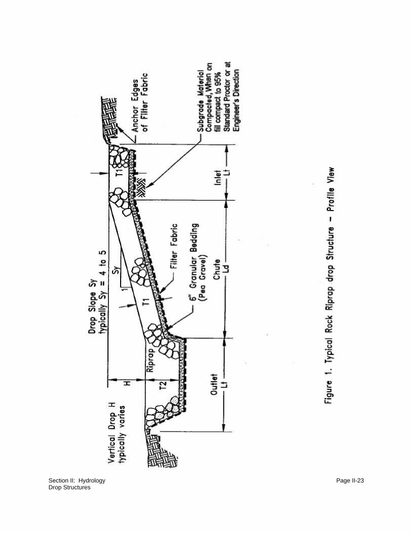
Section II: Hydrology Page II-23Drop Structures

Section II: Hydrology Page II-24Drop Structures

Section II: Hydrology Page II-25Drop Structures
minimum of one foot of freeboard. Freeboard allowance should be increasedwherever possible, particularly where turbulent forces are anticipated; e.g. at thebottom of the structure. The side slope Z of the structure should be no steeper than2.5H:1V and should be flatter under larger design discharges. The bottom width ofthe structure should be similar to the bottom width of the upstream channel.Similarities in channel geometry will make construction easier and improve thehydraulics through the structure. Bottom widths of the drop structure typically rangefrom eight to sixteen feet. Anything less than eight feet in width is more difficult toconstruct. Most structures typically have widths varying from 12 to 16 feet.
Two of the most important factors in constructing a sound rock riprap drop
structure, include: (1) obtaining rock with a proper gradation and shape, and (2)
utilizing a durable and sound rock type. The rock size for the structure is based on
median rock diameter, D50. The rock should be angular, blocky and have a uniform
gradation to ensure that the individual rocks will interlock with minimum void space.
The gradation is based on the D50 diameter:
D100 = 1.5 to 2.0 times D50
D20 = 1/3 to 1/4 times D50
Rock sizes for the gradation are usually specified by one-quarter foot increments,
i.e. D50= 0.5 feet (6 inches), D50=0.75 feet (9 inches), D50=1.0 foot (12 inches). A
median rock diameter greater than 2.0 feet (24 inches) with the proper gradation
is difficult to obtain from most quarries. Generally, the rock riprap for drop
structures will have D50 diameters less than 1.5 feet (18 inches). Good quality rock
is essential for the long term success of the structure. The following rock properties
are recommended:
(a) The rock should be durable;
(b) The rock should have blocky-angular shape;
(c) The rock source should be free of organic material, clay, shale seams, or
other structural defects;
(d) The riprap should have a specific gravity of at least 2.50.
Lesser quality rock may by used in site specific situations, where the design flow
is relatively small and/or the structure has a small drop. In some instances

Section II: Hydrology Page II-26Drop Structures
sub-standard rock can be anchored by vegetation or may be installed in a structure
with a relatively short design life or at a site with minimal adverse consequences
of failure. Standard construction specifications (ASTM) will provide rock testing
requirements. Riprap sources which do not meet these properties may be utilized,
but design modifications may be required. The designer will need to ensure that the
rock quality will not compromise the stability of the structure.
Some measure of protection is required below the drop structure, to prevent failure
or winnowing of the underlying soils. This can be accomplished with a graded
granular filter or a granular bedding used in conjunction with a geotextile fabric (see
Figure 2). Frequently the granular bedding is a pea gravel overlying the geotextile
fabric. The fabric will protect the bed material from being "washed out" from below
the structure and the granular bedding will protect the geofabric, as angular rock
is being placed on the fabric.
There are some guidelines that should be observed during the construction of a
rock drop structure. The construction inspector will need to ensure that the rock has
a gradation corresponding to the design specification. He will also need to ensure
that when the rock is handled (stockpiling and placing), segregation of the rock
does not occur. The structures should be constructed from the bottom to the top
to minimize the potential of rock segregation.
(2) Gabion Drop Structures
Gabions are wire enclosed baskets filled with rock. The combined weight of the
rock in the enclosed structure can withstand higher flow velocities and hydraulic
forces when compared to individual stones within a "loose" rock riprap structure.
A gabion structure often can utilize on-site rock recovered during mining
operations. A range of basket sizes available for construction are listed in Figure 3
A typical layout for a gabion drop structure is presented in Figures 4 and 5. As
indicated in the figures, the structures are typically constructed with a stepped profile
in both the longitudinal and lateral direction. When the gabions are placed, each
basket should overlap no less than one-half the length of the underlying basket (see
Figure 5). The baskets will also need to be adequately keyed into the channel bank
and bed to prevent failure of the structure by cutting or breaching. An inlet and
outlet transition section, similar to that required for rock riprap drops, should be
constructed. The individual baskets are also bound to each other with wire
fastenings.

Section II: Hydrology Page II-27Drop Structures

Section II: Hydrology Page II-28Drop Structures
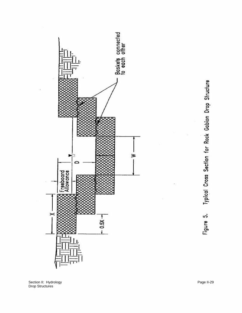
Section II: Hydrology Page II-29Drop Structures

Section II: Hydrology Page II-30Drop Structures
Design criteria for the gabion structures is typically based on channel velocity,
depth of flow, or the gabion's ability to withstand the force of the flowing water.
Specific gabion manufacturers should be contacted regarding design criteria for
each basket size. The allowable flow velocity and shear stresses are based on the
basket thickness, rock size, and rock specific gravity. For example, and according
to manufacturer's recommendations, a basket with a thickness of 1.6 feet, filled
with rock with a D50=7.5 inches and specific gravity of 2.5, should remain stable for
flow velocities less than or equal to 10 feet per second.
One of the advantages of gabions in drop structure design is the ability to use "on-
site" rock for the construction of the structure. However, the rock used to fill the
basket should still meet the following criteria: (1) diameter of 5-10 inches; and (2)
be durable and free of any structural defects. The designer should be aware that
certain rock types, like "clinker" or "scoria", have relatively low specific gravity and
poor durability. When utilizing sub-standard rock, structure design (basket size and
rock diameter) and placement of the individual baskets should address the
limitations of the rock. If low specific gravity rock is utilized, a larger basket
thickness and/or larger individual diameter rock will be required to achieve the
same level of protection at the individual structure.
For typical applications, the authors have found that galvanized coated gabion
baskets meet most design requirements at a lesser cost. If the structure is placed
on corrosive soils or exposed to caustic waters or acid drainage, use of
polyethylene coated basket wire will extend the design life of the basket at an
increased cost. High Density Polyethylene (HDPE) baskets are also available at an
even greater cost. HDPE baskets have higher puncture resistance, longer
durability, and are easier to transport and assemble. The increased unit cost must
be weighed against design intent, transportation costs, and labor factors.
Design criteria for the gabion structures is typically based on channel velocity,
depth of flow, or the gabion's ability to withstand the force of the flowing water.
Specific gabion manufacturers should be contacted regarding design criteria for
each basket size. The allowable flow velocity and shear stresses are based on the
basket thickness, rock size, and rock specific gravity. For example, and according
to manufacturer's recommendations, a basket with a thickness of 1.6 feet, filled
with rock with a D50=7.5 inches and specific gravity of 2.5, should remain stable for
flow velocities less than or equal to 10 feet per second.
One of the advantages of gabions in drop structure design is the ability to use "on-
site" rock for the construction of the structure. However, the rock used to fill the

Section II: Hydrology Page II-31Drop Structures
basket should still meet the following criteria: (1) diameter of 5-10 inches; and (2)
be durable and free of any structural defects. The designer should be aware that
certain rock types, like "clinker" or "scoria", have relatively low specific gravity and
poor durability. When utilizing sub-standard rock, structure design (basket size and
rock diameter) and placement of the individual baskets should address the
limitations of the rock. If low specific gravity rock is utilized, a larger basket
thickness and/or larger individual diameter rock will be required to achieve the
same level of protection at the individual structure.
For typical applications, the authors have found that galvanized coated gabion
baskets meet most design requirements at a lesser cost. If the structure is placed
on corrosive soils or exposed to caustic waters or acid drainage, use of
polyethylene coated basket wire will extend the design life of the basket at an
increased cost. High Density Polyethylene (HDPE) baskets are also available at an
even greater cost. HDPE baskets have higher puncture resistance, longer
durability, and are easier to transport and assemble. The increased unit cost must
be weighed against design intent, transportation costs, and labor factors.
(3) Rock Riprap Sizing
There are numerous sources and procedures available for determining the rock
size requirements for a drop structure. Listed below are three sources that present
different procedures for sizing rock riprap:
"Design Manual for Water Diversions on Surface Mine Operations",
Prepared for the Office of Surface Mining, Fort Collins, CO. (Simons Li &
Associates, Inc., 1982). This publication presents sizing criteria based on a
design flowrate and the channel geometry.
"Rock Riprap Design for Protection of Stream Channels near Highway
Structures, Volume II Evaluation of Riprap Design Procedures".
(Blodget & McConaughy, 1986) This publication presents numerous design
procedures for sizing rock riprap developed by the Army Corps of
Engineers, Federal Highway Administration, State Department of
Transportation and the Bureau of Reclamation (USBR).
"Hydraulic Design of Stilling Basins and Energy Dissipators". (Peterka,
1958) This publication presents an analysis of existing USBR instal-lations

Section II: Hydrology Page II-32Drop Structures
and includes a design nomograph, which sizes riprap based on bottom
velocity versus weight of rock.
When reviewing a procedure to size rock riprap for a drop structure, the designer
will need to ensure that the procedure is valid for the intended application. For
example, if the design procedure was developed for rock placed on channel banks,
it may not be applicable for sizing the rock riprap placed on the chute section of a
drop structure. Some design procedures assume a specific gravity of 2.65 for all
rock. Many otherwise suitable rock types, including limestone and leucite, have
lower specific gravities. In these cases the rock may be "up-sized" to account for
its lower unit weight.

Section II: Hydrology Page II-33
NOTES

Section II: Hydrology Page II-34Backfill Impoundments
4. Backfill Impoundments
Section editor: Frank K. Ferris Subsection author: Frank K. Ferris/Patrick T. Tyrrell
~~~~~~~~~~~~~~~~~~~~~~~~~~~~~~~~~
Situation:
Water structures are needed on a mine site for water treatment and storage. Impoundments
created in backfill voids are usually more cost effective than impoundments on unmined areas.
Special Considerations:
Uncompacted backfill slopes may not be stable enough to support equipment if the slopes become
saturated.
Description of Technique:
a. Design Considerations
Incised backfill impoundments are created by leaving a void area in the backfill and grading
the slopes. Though simple, the following basic design features need to be considered: size,
shape, cells, inlet structures, Mine Safety and Health Administration (MSHA) criteria,
stability, location, function, and construction. The function of a reservoir will determine the
extent that the design incorporates features for water treatment (shallows, cells, flat slopes,
length approximately four times width) or water storage (deeper, steeper sides, length to
width ratio variable).
In general, reservoirs should be designed with water treatment in mind, as good water
quality is important for any function, and the incremental cost of a treatment reservoir is low
compared to reworking or repairing any features of an inexpensive water storage reservoir.
Backfill impoundments primarily intended to store water can be deeper, with shape dictated
more by available topography, and with a reduced high-water line area to minimize
evaporation.

Section II: Hydrology Page II-35Backfill Impoundments
1) Size
The structure must be large enough to handle the design runoff event plus any pit
or process water, and may include additional capacity for dust control or to provide
a convenient location to hold excess runoff and minimize offsite discharges. Backfill
impoundments with at least 100 acre-feet of water storage are commonplace for
large surface mines. This large capacity provides flexibility in pumping and holding
large volumes of water in the structure until a discharge is convenient or can be
avoided. A larger size reservoir is more conducive to treatment and recycling of
water from washing operations. Such a reservoir provides the treatment and
storage capacity for dry periods when other sources of water become less reliable.
(2) Shape
If water treatment is the primary purpose of the reservoir, it will be the most
effective in a long, shallow (two to three feet deep) reservoir with the inlets as far
as possible from the water discharge location. This assures the shortest distances
for sediment to drop to the bottom, and limits short circuiting (inflow water travelling
directly to the pond outlet). As a guide, a backfill reservoir intended primarily for
water treatment should average 5 to 30 feet deep, 200 to 500 feet wide, and 500
to 4000 feet in length, depending on the volume to be treated. Side slopes should
be 3H:1V to 4H:1V to accommodate access by people and wildlife (see Figure 1).
Angle of repose slopes 1.5H:1V that become saturated will likely fail. Mobile heavy
equipment should be kept off the saturated, uncompacted slopes
characteristic of this type of impoundment.
(3) Cells
Cells should be strongly considered to control any oil spill that might enter the
reservoir, limit wave fetch, and eliminate short circuiting caused by temperature
inversions (i.e. warm plant water). The connections between cells typically would
be culverts installed below the water surface.
All cells should be designed to be at the same elevation regardless of the reservoir
volume. Because the base and sides of the reservoir and the dividing embankment
are not compacted, cells with differing water levels will likely have piping or
seepage from cell to cell. As the soil settles, failure between cells is likely.

Section II: Hydrology Page II-36Backfill Impoundments
FIG
UR
E 1
NO
SC
AL
E
FU
TU
RE
WA
TE
R L
EV
EL
BE
RM
TO
P O
F D
UM
P
LO
WE
R D
UM
P
10 T
O 3
O F
EE
T
6' T
O 1
0'
5 –1
5''
33
11
1
11.
5
3 T
O 4
AN
GLE
OF
REP
OSE
GR
AD
ED
SLO
PE

Section II: Hydrology Page II-37Backfill Impoundments
Impoundments constructed primarily for water storage reservoirs do not necessarily need
a dividing embankment.
(4) Inlet Structure
Inlet structures must be considered for any reservoir that is expected to function
more than one year. Surface or pipeline water that is released above the high-water
line and washes down an unprotected slope will cause significant erosion in one
season, and much quicker if there is a continuous water flow. The washing of slope
soil into the reservoir bottom will quickly fill the lower reservoir volume up to, or
possibly clog, a connecting culvert or pump culvert, and will compromise the
already marginal stability of the uncompacted slope. One option is a culvert to
deliver inflow below the water surface. If the pipeline inlet is on the reservoir floor,
it will generally stir up sediment and decrease the reservoir's water treatment
effectiveness. Using the same culvert for inflow and outflow can be done, but
should only be considered if the quality of the source water is very clean. Pumping
sediment laden water into the pump culvert will cause pump problems. See Figures
2, 3, and 4.
(5) MSHA
Generally, MSHA has jurisdiction over any water structure that stores 20 acre-feet
or more of water or slurry behind an embankment that is five feet or higher, as
measured from the upstream toe to the emergency spillway, or has an
embankment that is 20 feet or higher. A 100 acre-feet or larger reservoir normally
falls within this criteria.
An incised backfill reservoir does not have a compacted embankment storing water
above the surrounding ground level. This generally eliminates such impoundments
from MSHA jurisdiction. MSHA and the mines have used the following rule of thumb
to qualify the reservoir as incised: backfill 200 to 300 feet wide between the
reservoir and the pit, and higher than the reservoir. In 1993, MSHA qualified this
by stating that for a structure to be incised and not require design approval, the
minimum backfill slope from the high-water line to the pit floor had to be at least
10H:1V.

Section II: Hydrology Page II-38Backfill Impoundments
FIG
UR
E 2
NO
SC
AL
E
WA
TE
R L
EV
EL
13
TO
4
BE
RM
6' T
O 1
0'
3' T
O 5
'3'
5'
PU
MP
ON
E W
AY
VA
LV
E
2' D
RA
IN P
IPE
W/V
AL
VE
MIN
IMU
M 4
' DIA
.
6" T
O 8
" C
ON
CR
ET
EP
AD
— 8
' X 8
'(C
UL
VE
RT
DIA
ME
TE
R +
4')

Section II: Hydrology Page II-39Backfill Impoundments
NO
SC
AL
E
FIG
UR
E 3
HIG
H W
AT
ER
LIN
E
MIN
. WA
TE
R L
EV
EL
5' M
IN.
5' M
IN.
PO
LY
PIP
EL
INE
5'+

Section II: Hydrology Page II-40Backfill Impoundments
HO
LE
S IN
PIP
E
FIG
UR
E 4
NO
SC
AL
E
HIG
H W
AT
ER
LIN
E
MIN
. WA
TE
R L
EV
EL
5'+
CU
LVER
T
5' M
IN.
2' D
IA.
PIP
ELIN
E
SU
RF
AC
E
RU
NO
FF
IN S
AT
UR
AT
ED
UN
CO
MP
AC
TE
DB
AC
KF
ILL
TH
EC
UL
VE
RT
MA
Y T
RY
TO
FL
OA
T IN
AW
AT
ER
PO
OL
CO
UN
TE
R W
EIG
HT
TO
MA
TC
H P
IPE
FL
OT
AT
ION
Section II: Hydrology Page II-41Backfill Impoundments
(6) Stability
Uncompacted, saturated backfill is usually unstable when used to contain water or
support weight. When used with very flat slopes such as MSHA suggests (10H:1V),
stability should not be an issue.
The reservoir site must be conducive to water retention. This means the side
slopes and reservoir bottom must be soils that exhibit low permeabilities. Zones of
sand or waste coal in or in close proximity to the base or side are likely to cause
significant water loss through seepage. A very porous soil backfilled to the reservoir
may generate a seep on a backfill bench, if one is nearby.
(7) Location
The location should be chosen to maximize life and assure stability. The longer the
reservoir is used, the more cost effective it is. Designing an impoundment to be
non-MSHA is a major help in timing and cost. Position the reservoir where MSHA
jurisdiction is not required, and the saturated backfill does not become a future
obstacle to mining.
(8) Function
Multiple functions of water treatment, water storage for dust suppression, wildlife
use, and postmining land use should be considered in the given priority.
(a) Water Treatment
Water Treatment for pit, plant, or disturbed area water sources is usually the
primary concern. This reservoir is not likely the final treatment, but the initial
step to reduce the Total Suspended Solids (TSS).
(b) Water Storage
A second concern is water storage for use during dust control activities, for
storage of water awaiting treatment, or for simply providing a holding area
to minimize discharges or provide a water source in extended dry periods.

Section II: Hydrology Page II-42Backfill Impoundments
(c) Wildlife
A reservoir can be made to have some wildlife features at a minimal cost
(see the subsection entitled "Wetlands"). These features should be included
to show compatibility of the mining operation with wildlife.
(d) Postmining Land Use
It is an added bonus if the structure (or part of it) can be made part of the
postmining land use. Keep in mind that water sources may deposit coal
fines that should be covered before final reclamation. You may want to
design the reservoir to be partly buried by final reclamation to cover
unsuitable sediment.
(9) Construction
The construction cost-saving in this structure is the use of uncompacted fill for
water containment. Sides are dumped in and dozed to final slope (see Figure 1).
Berms are required by MSHA to prevent a vehicle from entering the impoundment.
A spillway needs to be installed to provide six to ten feet of freeboard. Freeboard
is from the high-water line when spilling to the top of the containing backfill bench.
Do not consider a compacted embankment on top of uncompacted backfill.
Differential settling of the backfill will negate the purpose of the compaction and
possibly cause failure of the embankment. For reservoir access, an old haul road
ramp is good (if one is present) for skid mounted pumps or other equipment,
because the base will remain firm. Compaction (minimum 90 percent standard
proctor is suggested) should be performed around dewatering pipe stands.
b. Dewatering
(1) Gravity Discharge
The simplicity of gravity discharge should be considered because no pump is
required. The downside is that it may not always provide surge capacity, there may
not be a good way to shut the system off, and a pump may be required to load

Section II: Hydrology Page II-43Backfill Impoundments
water trucks or recycle water. Also, gravity discharge is often not possible because
the reservoir is usually lower than the surrounding area.
(2) Pumps
Installation of two pumps should be considered to maintain reservoir capacity and
discharge system reliability. Pumps with durable, slower speed impellers are better
because they will last longer. Existing pump stock may dictate the pump to be
used. Pumps that are in continuous use for long periods should be electrically
driven, if power is available, because of the lower maintenance and cost compared
to diesel engine driven pumps.
Figure 2 illustrates a desirable pump evacuation method for longer duration
installations. Figure 5 illustrates the float and pump method, which is usually much
cheaper for up to three years duration. Access, safety, winter ice, and
maintenance make the land-based design much more desirable when it must be
used for many years.

Section II: Hydrology Page II-44Backfill Impoundments
FIG
UR
E 5
NO
SC
AL
E
PU
MP
& F
LO
AT

Section II: Hydrology Page II-45
NOTES
Section II: Hydrology Page II-46Straw or Hay Bale Check Dams
C. Alternative Sediment Control
1. Straw or Hay Bale Check Dams
Section editor: Frank K. Ferris Subsection author: Doyl M. Fritz
~~~~~~~~~~~~~~~~~~~~~~~~~~~~~~~~~
Situation:
Use straw or hay bale check dams when temporary sediment or erosion control is needed for one
season or less.
Special Considerations:
The channel slope is the most critical aspect, and should be twenty percent or less.
Description of Technique:
a. Definition
Straw or hay bale check dams consist of standard agricultural bales placed end-to-end in
rows across a sloping area of land.
b. Function
Straw or hay bale check dams provide a simple, inexpensive method for temporarily
controlling sediment by reducing the velocity of runoff and filtering sediment from the runoff.
c. Useful Life
These structures are short-lived and should only be utilized in temporary applications. The
useful life of a straw or hay bale check dam is dependent on many factors, but is typically
only a few months.

Section II: Hydrology Page II-47Straw or Hay Bale Check Dams
d. Design Recommendations
(1) Location
Use bale check dams in locations where the bales are not likely to be overtopped
by runoff (i.e. small drainage basins with shallow to moderate relief). Do not install
bale check dams in areas of highly concentrated flow, such as steep, narrow
channels and ditches.
(2) Placement
Place bale check dams along a contour or in shallow swales. Extend both ends of
the check dam in an uphill direction so that the elevations of the bottoms of the two
end bales are at or above the elevation of the top of the bales that are placed along
the contour. Place bale check dams on sloping land in accordance with the
following table:
Slope, percentMaximum slope length above a single bale checkdam or between successive bale check dams
2 or less 250
5 100
10 50
15 35
20 25
e. Installation Recommendations
Install straw or hay bale check dams as shown on Figure 1. Do not install straw or hay bale
check dams in areas where rock or rocky soil prevents full and uniform depth anchoring of
the bale check dam.
(1) Contouring (optional)
If bale check dams are placed in a graded channel, such as a roadside ditch, it is
sometimes advisable to place the check dams just downstream from a shallow
basin created with the scraper used to build the channel. Such basins provide

Section II: Hydrology Page II-48Straw or Hay Bale Check Dams
sediment storage space, reduce maintenance, and also temporarily pond water.
This enhances vegetation and provides temporary habitat for certain species of
birds and wildlife.
(2) Double Rows (optional)
A second line of bales offset behind the first can also be very effective.
f. Maintenance Recommendations
(1) Inspection
Inspect each bale check dam after every runoff event and at intervals not
exceeding one month.
(2) Repair
Reset, stake, and backfill any dislodged bales. Repair all undercutting of the anchor
toe with compacted backfill materials.
(3) Sediment Accumulation
Replace bales that have become damaged or clogged with sediment. Remove
accumulated sediment as required when uniform accumulations reach one-third the
height of the bale check dam.

Section II: Hydrology Page II-49Straw or Hay Bale Check Dams

Section II: Hydrology Page II-50Rock Check Dams
2. Rock Check Dams
Section editor: Frank K. Ferris Subsection author: Doyl M. Fritz
~~~~~~~~~~~~~~~~~~~~~~~~~~~~~~~~~
Situation:
Rock check dams should be used in steep, defined drainages when reduction of channelized runoff
flow velocity and filtration of sediment from channelized runoff is required for one year or more.
Special Considerations:
Failure to control the flow velocity of channelized runoff on disturbed or newly reclaimed land can
result in significant head-cutting in channels. Rock check dams may be used where flow is
channelized and flow velocity is too high for the use of other stabilization and sediment control
methods, such as straw or hay bale check dams or sediment fence. In addition, they may be used
when the duration of stabilization is needed for more than one season/event.
Description of Technique:
a. Definition
A rock check dam is a low, porous, loose-rock embankment that is intended to slow the
velocity of channel flow but not to impound water.
b. Function
Rock check dams control the flow velocity of channelized runoff and filter some sediment
from the runoff, thereby reducing erosion and transported sediment. They are usually
constructed in steep terrain and are most appropriate in narrow channels and ditches.
c. Useful Life
Indefinite.

Section II: Hydrology Page II-51Rock Check Dams
d. Design and Construction Recommendations
Design and construct rock check dams as shown on Figure 1.
(1) Placement
Place rock check dams across a swale, ditch, or channel, perpendicular to the
direction of flow. Space rock check dams in series along a channel, as required,
or in accordance with the following equation:
D = distance between successive rock check dams, in feet,
H = height of rock check dam, in feet, and
S = slope of channel, in feet-per-feet.
(2) Materials
Install toed-in woven filter fabric before placing rock check dams for those
structures intended to remain in place for an appreciable length of time.
Construct rock check dams with check dam rock alone if the sole purpose of the
dam is channel stabilization. Construct rock check dams with both check dam rock
and filter rock if increased check dam sediment removal capability is desired.
e. Maintenance Recommendations
(1) Sediment Accumulation
Remove accumulated sediment from immediately upstream of a rock check dam
at or before the time when the depth of sediment reaches one-half the height of the
check dam. Remove and replace rock check dams if they become completely
clogged with sediment.

Section II: Hydrology Page II-52Rock Check Dams
(2) Removal
Rock check dams may be removed or left in place if they have successfully served
their purpose. In grass-lined ditches or swales, rock check dams may be left in
place when the grass has matured sufficiently to protect the ditch or swale from
erosion. If it is desirable to remove the check dams, the areas exposed by removal
of rock check dams should be immediately seeded and mulched.

Section II: Hydrology Page II-53Rock Check Dams

Section II: Hydrology Page II-54Sediment Fence
3. Sediment Fence
Section editor: Frank K. Ferris Subsection authors: Doyl M. Fritz/John D. Berry
~~~~~~~~~~~~~~~~~~~~~~~~~~~~~~~~~
Situation:
Sediment fence should be used when sediment control is needed for one year or more.
Special Considerations:
Sediment fence may be installed as an alternative to straw or hay bale check dams. Sediment
fence may have a longer useful life than straw or hay bale check dams.
Description of Technique:
a. Definition
A sediment fence is a low geotextile fabric fence placed across a sloping area of land.
b. Function
Sediment fences control the flow velocity of overland runoff and filter sediment from runoff
without impounding water, thereby reducing erosion. The sediment removal efficiency of
sediment fence is typically high but varies depending on sediment particle sizes and the
quality of sediment fence installation and maintenance. Like straw or hay bale check dams,
sediment fences may be placed in series to increase sediment trapping efficiency.
c. Useful Life
The useful life of sediment fence may be indefinite, depending on flow magnitude and the
rates of sediment accumulation and fabric degradation due to weathering. Frequent
maintenance may be required to maintain the integrity of sediment fence that is left in place
during numerous major runoff events.

Section II: Hydrology Page II-55Sediment Fence
d. Types of Sediment Fence
Sediment fence is produced by most major geotextile manufacturers. It may be purchased
as prefabricated fence with preassembled posts, as fence fabric with regularly-spaced
pockets into which the purchaser places posts, or as fabric with a reinforced top edge and
no pockets for posts. Sediment fence fabric is available in varying widths (i.e. fence
heights), typically ranging from 2 to 3.5 feet.
e. Design Recommendations
(1) Support Structures
Support structures should be sturdy enough to withstand a considerable amount
of hydrostatic and sediment load pressure, particularly before vegetation has
become established. The fabric must be backed with support of some kind to keep
the water and sediment from pushing the bottom of the fabric out, causing a failure
underneath the fabric. Steel posts and wooden snow fence make an excellent
support structure. The steel posts can be placed in the bottom of a trench cut with
a motor grader and the snow fence is then wired to the posts with the bottom of the
snow fence in the trench. Bracing should be added to the back of the support
structure to ensure it will not be pushed over by water, sediment accumulation, or
wind. Bracing can be accomplished by using steel posts placed at an angle behind
every other upright post. It is helpful to use a cutting torch to cut small notches in
the uprights to accept the angled braces. The braces should be pounded into the
ground a minimal amount to keep them from sliding and should be wired to the
upright posts at the top.
(2) Fabric Quality
The sediment fabric should be high quality and UV resistant. The additional cost
of quality material will be more than made up for by additional labor required to
replace fabric that has deteriorated before sediment control release has been
obtained. The bottom of the fabric panel should be extended out from the support
structure in the trench at least one foot. The fabric can be wired directly to the snow
fence at five foot intervals or lathe can be wired to the side of the fabric opposite
the snow fence. The lathe keeps the wire from pulling through the fabric, which can
happen in areas prone to wind. The flap of fabric in the trench is covered with soil
once the structure is completed, to ensure water and sediment do not run under the

Section II: Hydrology Page II-56Sediment Fence
fence. This can be accomplished by using the motor grader to gently push the
material removed from the trench back over the fabric and refill the trench.
(3) Installation
Place sediment fence along a contour. Extend both ends of the sediment fence in
an uphill direction, so that the elevations of the bottoms of both ends of the fence
are at or above the elevation of the top of the fence that is along the contour.
Sediment fences installed in areas of concentrated flow, including channels,
ditches, and swales, should have small drainage areas.
(4) Design Parameters
Place sediment fence on sloping land in accordance with the following table:
Slope,percent
Maximum slope length above 12 to 18inch high sediment fence
Maximum slope length above 24 to30 inch high sediment fence
2 or less 250 500
5 100 250
10 50 150
15 35 100
20 25 70
25 20 55
30 15 45
35 15 40
40 15 35
45 10 30
50 10 25
f. Installation Recommendations
Install sediment fences as shown on Figure 1. Do not construct sediment fences in areas
where rock or rocky soil prevents the full and uniform anchoring of the fence toe.
Where the ends of sediment fence fabric come together, overlap, fold, and staple the two
overlapping ends.

Section II: Hydrology Page II-57Sediment Fence
g. Maintenance Recommendations
(1) Inspection
Inspect sediment fence and repair as required after every significant runoff event.
(2) Sediment Accumulation
Remove accumulated sediment at or before the time when the depth of
accumulated sediment reaches one-half the height of the sediment fence.
(3) Repair
Immediately repair with compacted backfill all undercutting or erosion of the
sediment fence toe anchor. Replace sediment fence that is degraded by
weathering in accordance with the manufacturer's recommendations.
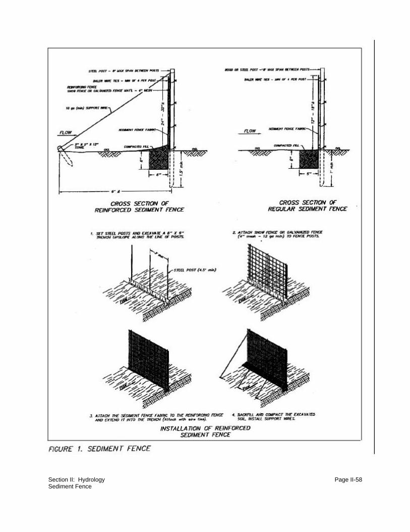
Section II: Hydrology Page II-58Sediment Fence

Section II: Hydrology Page II-59
NOTES
Section II: Hydrology Page II-60Gabion Baskets
4. Gabion Baskets
Section editor: Frank K. Ferris Subsection author: Doyl M. Fritz
~~~~~~~~~~~~~~~~~~~~~~~~~~~~~~~~~
Situation:
In high velocity, high volume, or long duration circumstances, gabion baskets should be
considered. Reduction of flow velocity or protection from erosion due to high flow velocity in
channels is sometimes required during mining and reclamation. Gabion baskets may be used to
construct check dams, drop structures, or pipe outlet aprons which are capable of withstanding
and/or reducing relatively high-velocity flow.
Gabion basket structures are relatively simple to install and are generally more durable than
comparable loose-rock structures. They allow the use of much smaller rock than could be used
under similar flow conditions without the wire baskets. They also offer an advantage over rigid
concrete structures because they are flexible and can conform to changes in subgrade conditions
caused by erosion and settlement.
Special Considerations:
Generally, baskets with a thickness of less than one foot should be avoided. Fabric under the
basket and sufficient rock gradation within the basket are necessary to assure minimum flow
velocities against the soil under the basket. Otherwise, erosion may undercut the baskets.
Description of Technique:
a. Definition
The term "gabion basket" as used herein applies both to Reno mattresses, which are from
6 to 12 inches thick, and to gabion baskets, which are typically 18 inches or more thick.
Both Reno mattresses and gabion baskets are rectangular, rock-filled, wire-mesh boxes
that are purchased disassembled and are assembled, filled with rock, and staked in place
at the construction site.

Section II: Hydrology Page II-61Gabion Baskets
b. Function
Figures 1 through 3 provide examples of gabion structures. Gabion baskets are used to
construct check dams, drop structures, and pipe outlet aprons that are intended to
withstand and/or reduce relatively high flow velocities. Construction of gabion basket
structures is relatively simple and requires no special construction skills. Gabions can also
be used to line temporary diversion channels where flow velocities exceed 5 feet-per-
second (e.g., see cross section C-C' on Figure 2 and cross section A-A' on Figure 3).
c. Useful Life
Indefinite. The useful life of a gabion basket structure is usually longer than that of a
comparable loose-rock structure, and they may outlast rigid concrete structures in some
applications. Their durability is dependent on the quality of the rock and wire used in
construction. The use of durable rock and heavy gage, corrosion resistant baskets will
provide the longest useful life.
d. Design and Construction Recommendations
Design and construct gabion basket structures as shown on Figures 1 through 3.
(1) Design Parameters
Gabion basket structures should be designed in accordance with the parameters
recommended in the following table:
TypeManning's
"n"Thickness(inches)
Rock fill gradation (inches)
Permissible flowvelocity
(feet/second)
Renomattress
0.025 6 3 - 6 13.5
Renomattress
0.025 9 3 - 6 16.0
Renomattress
0.025 12 4 - 6 18.0
Gabion 0.027 18 + 5 - 9 22.0

Section II: Hydrology Page II-62Gabion Baskets
(2) Materials
Durable rock such as limestone or granite should be used to fill gabion basket
structures that are intended to remain in place for extended periods of time. Scoria
rock may be used in temporary gabion basket structures, but longevity and
permissible flow velocities may be reduced by use of the less durable scoria rock.
One or two layers of woven filter fabric may be used to protect underlying soils.
Two layers of fabric will provide additional protection in case the top layer is
punctured or torn during installation.
e. Maintenance Recommendations
(1) Sediment Accumulation
Remove accumulated sediment from immediately upstream of a gabion basket
check dam, at or before the time when the depth of sediment reaches one-half the
height of the check dam.
(2) Repair
Repair broken wire baskets and replace lost or displaced rock as necessary.
(3) Removal
Remove temporary gabion basket structures when their useful lives are completed.
In grass-lined ditches or swales, gabion basket check dams may be removed when
the grass has matured sufficiently to protect the ditch or swale from erosion.
Immediately seed and mulch areas exposed by removal of gabion basket
structures.
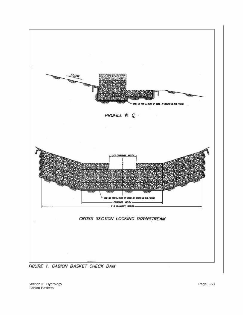
Section II: Hydrology Page II-63Gabion Baskets

Section II: Hydrology Page II-64Gabion Baskets

Section II: Hydrology Page II-65Gabion Baskets

Section II: Hydrology Page II-66Vegetative Filters
5. Vegetative Filters
Section editor: Frank K. Ferris Subsection author: Richard C. Warner
~~~~~~~~~~~~~~~~~~~~~~~~~~~~~~~~~
Situation:
Vegetative filters have been investigated as a sediment control mechanism for protection of
streams. They have been predominantly used as riparian buffer strips in agriculture (Dillaha et al.,
1989, Parsons et al., 1991) and have been analyzed, in experimental settings, for a surface mine
(Barfield and Albrecht, 1982), and a construction site (Hayes and Harrison, 1983). Reported
sediment trap efficiencies for these experiments range from 70 to greater than 90 percent. Grass
filters have been designed to achieve these high efficiencies only when overland flow has been
established and directed towards the filter.
Special Considerations:
For grass filters to function at high efficiencies, runoff entering the filter must be maintained as
overland flow. Dillaha (1989) concluded that the effectiveness of vegetative filter strips in removing
sediment and nutrients from cropland runoff were relatively ineffective due to concentrated flows
entering the filters. Sediment-laden waters approaching a vegetative filter are slowed through
backwater effects and deposition occurs up-gradient of the filter and in the upper portions of the
filter. Dillaha found that after deposition occurred, later runoff events would be transported along
the previously deposited sediment barrier until a low spot was reached and then pass as
concentrated flow through the filter, thus significantly reducing the effectiveness of the filter. Also,
natural depressions in the landscape further exacerbated the problem of developing concentrated
flows. For vegetative filters to function properly, overland flow must be established and maintained.
Description of Technique:
Hayes and Dillaha (1991), developed procedures for the design of vegetative filters. Coarser
particles are deposited by settling in the reduced velocity created in the up-gradient portion of the
filter, whereas finer particles are removed through infiltration at the lower portion of the filter. From
this basic knowledge, primary design parameters can be determined. Overland flow must exist.

Section II: Hydrology Page II-67Vegetative Filters
Thus grass density should be high and the selected grass must be able to resist flow without
bending to the ground. The drainage area generating runoff must be relatively small and situated
such that overland flow proceeds to the filter without concentrating. The filter length should
accommodate deposited sediment and be sufficiently long to enable time for infiltration of runoff.
The selected soils should have a relatively high infiltration rate if the smaller size fraction of
sediment is required to be captured.
For mining applications design considerations seem to restrict the use of grass filters to ideal
conditions. How can these restrictions be relaxed? If only settleable solid trapping is needed, the
length of the filter can be significantly reduced. Dillaha used vegetative filters in the range of 15 to
30 feet. Overland flow must be established and maintained. This is difficult in a natural setting
because of the tendency to deposit sediment up-gradient of a filter. It is my recommendation to use
vegetative filters in conjunction with a sediment filter fence. The silt fence accomplishes these
functions: (1) changing concentrated flow to overland flow as discharge is contained behind the
silt fence and subsequently transported through the filter, (2) a large portion of coarser particles
are settled behind the sediment fence thereby reducing the need for storage capacity within the
vegetative filter, (3) discharge through the silt fence will be low and relatively uniform which enables
infiltration, and associated capturing of the finer sediments to be accomplished, and (4)
maintenance, i.e. sediment removal, is easily conducted. Thus, the vegetative filter functions as
a secondary treatment system which will further reduce effluent concentration entering the fluvial
system.
Ideal application areas are along lateral developments such as haul roads, railways, etc., where
directing runoff to sediment basins may be economically infeasible. The SEDCAD+ program has
a vegetative filter predictive algorithm which will assist in determining the sediment trap efficiency
and reduction in flow as a function of filter input parameters for a design storm event.

Section II: Hydrology Page II-68Small Drainage Waterway Construction
D. Reconstruction of Hydrologic Features
1. Small Drainage Waterway Construction
Section editor: Frank K. Ferris Subsection authors: Frank K. Ferris/Christopher D. Lidstone/C. Marty Jones
~~~~~~~~~~~~~~~~~~~~~~~~~~~~~~~~~
Situation:
Concentrated flow from small drainage areas usually causes the most erosional problems because
a waterway of some type has not been provided.
Special Considerations:
When runoff is generated from a small area as unconcentrated flow and is routed over a steep
area, the flow coalesces and becomes concentrated flow. The erosive energy of this concentrated
flow increases as additional water is added to the system or as it gains energy traversing the
steeper slope. Rills, gullies, and headcuts are formed, where no designed channel existed.
Anticipating where the flow will coalesce into concentrated flow and "cutting a waterway" will
eliminate or reduce rill and gully erosion.
Contributing drainage basin area is an important consideration in small drainage waterway
construction. A rule of thumb may suggest that a small drainage will form for every three to seven
acres of contributing basin area. However, there are many variables which affect the development
of lower order drainages, including: contributing basin area; basin slope; length of overland flow;
slope aspect; and soil or parent material. Many operators collect adequate baseline geomorphic
data to assist in prediction of where a small waterway will form. A standard geomorphology text will
assist the operator in the selection, measurement, and analysis of relevant morphometric
parameters. Specifically, drainage density (total channel length divided by basin area), frequency
of first order channels (total number of first order channels divided by the basin area), and the
constant of channel maintenance (number of acres of contributing basin area to establish a first
order channel) are important parameters.

Section II: Hydrology Page II-69Small Drainage Waterway Construction
Description of Technique:
a. The two aspects of waterway design that need to be considered are the channel water and
the inflow from adjacent areas. A flat bottom channel (10 to 12 feet wide) with gentle side
slopes reduces flow depth, decreases water concentration, and increases the wetted
perimeter. These factors help reduce water velocity which helps control erosion. The
channel provides enough water concentration to help sod formation.
Reclamation grading needs to occur with a focus on the water flow from the reclaimed
surface. Waterways need to be constructed to the main channel. The waterway grade
should continue to get flatter along its route to the design channel. There are three
general types of areas that should have waterways:
(1) Flat to Gently Sloped Fields
Large fields usually have an area where water ponds, or during large runoff
events, ponds and flows in some direction. On reclaimed land where differential
settling will occur, it is best to create a waterway to a designed channel. This
prevents head cuts where water exits the field and enters the channel. A waterway
should start near the low point of a field and go to the design channel. This is
illustrated on Figures 1 and 2.
(2) Long, Moderate Slopes
Long, moderate to steep slopes should be broken by shallow ridges and
waterways. Because long slopes of expected sheet flow form concentrated flow
and gullies, the length of slope and drainage area should be limited to five acres
or less. The drainage area is the most critical factor to determine channel stability.
Use waterways and ridges in conjunction with other micro-topography features to
break a slope and concentrate the runoff in areas where sod will form and
stabilize a waterway. Figure 3 shows this in plan view and cross section.
(3) Backfill Dumps
Large, wide, elevated dumps will require establishing an interior drainage to an
access ramp for a shallow gradient waterway off the top of the elevated backfill
dump. Otherwise, direct flow over the exterior slopes will cause extensive erosion.

Section II: Hydrology Page II-70Small Drainage Waterway Construction
If there is a choice, the channel gradient should be almost flat to promote
infiltration. Establishing a small playa may also be an option.
The ramp gradient is usually too steep for non-erosive flow. Extensive grading, or
routing the channel onto a bench that is 10 to 20 feet lower, is usually needed to
get an acceptable channel gradient. Figure 4 shows the interior drainage route
from a large elevated backfill dump. Figure 5 shows how one can transform the
top surface of a dump, using loose dumps and grade control, into an interior
drainage system.

Section II: Hydrology Page II-71Small Drainage Waterway Construction
FIGURE1
AA
B B
CC
FIELD
FIELDFIELD

Section II: Hydrology Page II-72Small Drainage Waterway Construction
FIELD CENTER
FIGURE 2
20 MIN 20 MIN
20 MIN
1 1
120 MIN
1
C C'
B'
A'A
B
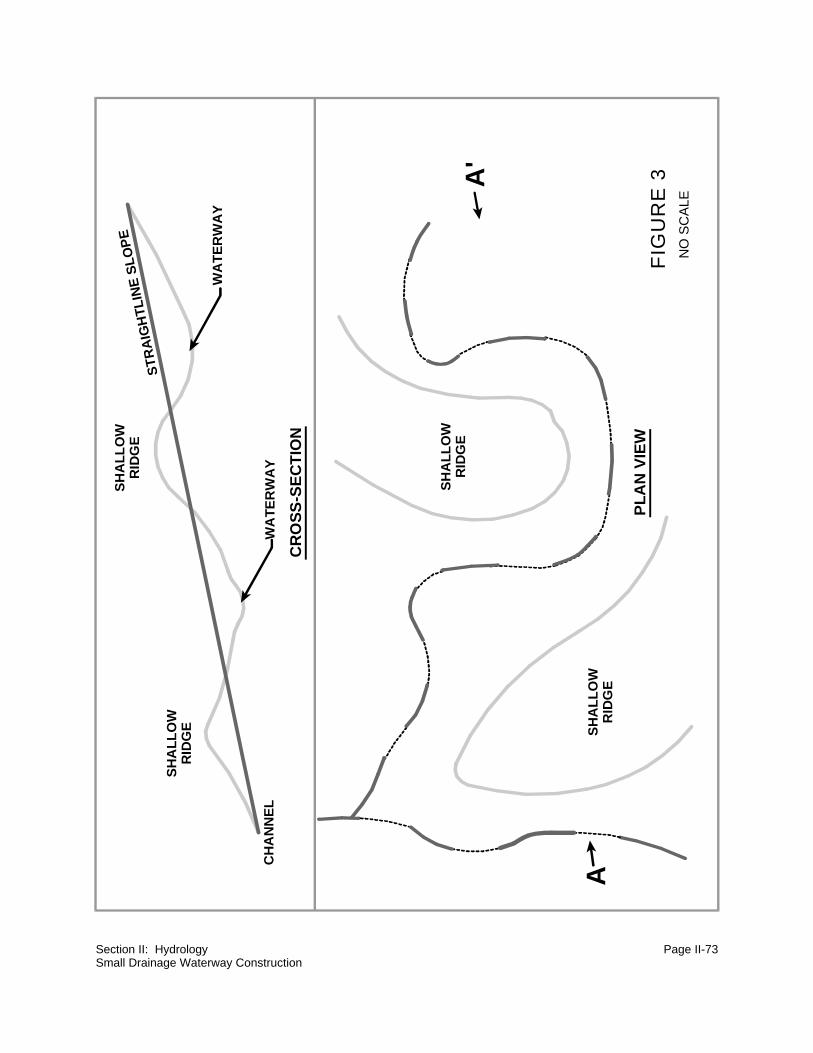
Section II: Hydrology Page II-73Small Drainage Waterway Construction
A
A'
NO
SC
ALE
FIG
UR
E 3
CR
OS
S-S
EC
TIO
N
SH
AL
LO
WR
IDG
ES
TR
AIG
HTL
INE
SL
OP
E
WA
TE
RW
AY
WA
TE
RW
AY
PL
AN
VIE
W
SH
AL
LO
WR
IDG
E
SH
AL
LO
WR
IDG
E
CH
AN
NE
L
SH
AL
LO
WR
IDG
E

Section II: Hydrology Page II-74Small Drainage Waterway Construction
NO SCALE
FIG
UR
E 4
GR
AD
ED
LOO
SE
DU
MP
S
CH
ANNEL
FLO
WLIN
E
GR
AD
ED
LOO
SE
DU
MP
SG
RA
DE
DLO
OS
E D
UM
PS
TRUCK ROAD
SLOPE
SLOPE
SLO
PE
SLOPE
SLOPE
SLOPE
SLO
PE

Section II: Hydrology Page II-75Small Drainage Waterway Construction
FIG
UR
E 5
15
1.5
1
A'
AC
HA
NN
EL
LOO
SE
DU
MP
SLO
OS
E D
UM
PS
CR
OS
S-S
EC
TIO
N G
RA
DE
D
CR
OS
S-S
EC
TIO
N W
ITH
LO
OS
E D
UM
PS
CR
OS
S-S
EC
TIO
N B
AC
KFI
LL D
UM
P W
ITH
GR
AD
E C
ON
TRO
L
STA
GE
S O
F D
UM
P G
RA
DIN
G
NO
SC
ALE

Section II: Hydrology Page II-76Stream Channel Construction
2. Stream Channel Construction
Section editor: Frank K. Ferris Subsection author: Richard C. Warner
~~~~~~~~~~~~~~~~~~~~~~~~~~~~~~~~~
Situation:
Often mining operations require the relocation and reconstruction of streams or stream
modifications to increase discharge capacity.
Special Considerations:
An assessment of premining stream parameters and an understanding of flow characteristics
necessary for food production, spawning and cover (i.e. habitat) will greatly increase the
opportunities for success. Besides stream morphologic parameters, an understanding of stream
velocity, depth, and substrate will facilitate construction of a balanced, diverse aquatic ecosystem.
Description of Technique:
a. Planning
The development of a successful reclamation plan that addresses stream considerations
is based on the acquisition of premining stream data. A base map normally displays a
planview of the channel, flood plains, and generalized vegetation documentation. Such data
can be readily obtained through aerial photos or the existing channel can be surveyed. A
stream longitudinal profile is extracted. This profile displays distance from a specified
downstream location, reach segment number, length and slope of each reach, meander
characteristics and cross-section measurements for each reach. The meandering pattern
as described by wavelength, sinuosity (ratio of valley slope to stream slope), and radius of
curvature. Numerous other meander patterns and characteristics can be helpful in stream
reconstruction (Gore, 1985). Meandering has been identified as the primary vehicle of
dissipating stream energy and is therefore a principle design tool for stream reconstruction.

Section II: Hydrology Page II-77Stream Channel Construction
A vertical profile of channel substrate should be detailed for each stream environment, i.e.
pool and riffle. Each layer of the vertical profile should contain particle size composition.
Note should be made of stream geometric factors such as cross-section shape, stream
pattern (meandering patterns and braided), and pool-riffle patterns. Also location and
description of point bars and cross currents should be noted.
b. Stream Habitat Components
To enhance stream relocations, it is necessary to gain an understanding of the interplay
among aquatic habitat factors and physical factors of stream velocity, depth, and substrate.
In a pool-riffle environment, riffles function as food production and spawning areas. Riffles
exhibit relatively shallow depths, higher than average velocity, and coarser substrate than
pools. Velocity is the primary parameter describing the distribution of aquatic invertebrates.
Velocity in riffles governs the rate of oxygen transfer to properly sized substrate (i.e. rubble,
boulders, and cobbles) thereby supplying oxygen and removing metabolic waste products
from intergravel areas. Water velocity increases the exchange rate, thereby enhancing
respiration and food acquisition. Optimal velocity is subject to debate, but the range for riffle
segments for good stream productivity is between 0.5 and 3 feet-per-second (fps) or 0.15
and 0.9 meters-per-second (mps) (Delisle and Eliason, 1961). A narrower design range is
1 to 2 fps or 0.3 to 0.6 mps (Giger, 1973).
Velocity controls substrate size to a large extent. The larger size rocks are associated with
riffle areas since sands and silt are removed by the higher current velocity. Benthic
invertebrates decrease in number and diversity as substrate is changed from rubble to
coarse gravel to fine gravel and sand. Rubble appears to play a key role in the riffle
environment. It provides a broad surface for invertebrates to cling to and functions to
protect insects from high velocities (Gore,1985). Velocity also functions as the vehicle for
drift, which is the movement of organisms downstream by current. Drift supplies the
mechanism to acquire food which advances increased population densities and diversity.
Depth controls, to a great degree, the intensity of light which controls photosynthetic
production of food. Deeper waters are less productive and contain fewer invertebrates than
shallower riffle areas. Depth of highest productivity in trout streams range from 0.5 to 3 feet
(0.15 to 0.9 meters), provided that current and substrate are suitable (Gore, 1985).
The parameters of velocity, depth and substrate combine in the riffle environment to provide
an optimal habitat for aquatic invertebrates (Gore, 1985). The repetitive pool-riffle
succession creates an excellent habitat for food production, spawning, cover, and resting.

Section II: Hydrology Page II-78Stream Channel Construction
Stream cover can take many forms. Bank cover is provide by overhanging vegetation and
undercut banks whereas in-stream cover is found by aquatic vegetation and the larger
substrate. When reconstructing a stream, cover is essential. Elser (1968) found a reduction
of 78 percent less trout in a stream having 80 percent less cover.
c. Structures to Enhance Stream Habitat
Structures such as current deflectors, low profile dams, and the selective placement of
boulders and substrate during channel reconstruction can enhance habitat. Such devices
can locally increase velocity, create pools and scour holes, provide gravel trapping areas,
remove silt from spawning areas, protect stream banks, enhance pool-riffle sequencing,
aerate the water, reduce or increase water temperature, and generally both create
enhanced habitat and simultaneously provide bank stabilization.
d. Current Deflectors
Current deflectors are structures extending outward from the streambank into the channel.
Common terms for these devices are jetties, spur dikes, groins, etc. As with many controls,
deflectors have been reported to be both successfully and unsuccessfully employed.
Wesche (1985) reviewed numerous applications and reported successes summarized by
phrases such as "the number of age 1 and older brook trout had doubled in the modified
reach"; "the number of good quality pools had increased from nine to twenty nine, average
pool depth had increased by 0.5 feet (0.15 meters), and additional spawning gravel had
been exposed"; and "...improved the carrying and reproductive capacity of the reach for
trout, was cost effective when compared with stocking, and had their greatest effect on the
substrate, increasing the exposed gravel in each reach from 14 to 24 percent". Wesche
(1985) also summarized failures such as "...deposition which occurred immediately
downstream from the structure negated any habitat gains"; "...deflectors were quite
susceptible to damage and needed frequent repairs"; and "flood flows reduced the ability
of certain structures to concentrate the flow, while the pools provided little trout cover".
To be effective, deflectors require application of design methodology and rigorous
construction methods. Unfortunately, few design aids exist for the proper sizing, location
and spacing of deflectors. Consideration should be given to: (1) location along the reach,
i.e. locate along a straight or concave (the bank at the outside of the bend) stream section;
(2) spacing among a sequence of deflectors; (3) location of riffles; (4) stability of the
substrate; (5) ability to anchor the deflector in the bank; (6) bank height and stability; (7)
point-bar deposition location; (8) bed transport; and (9) specific deflector design

Section II: Hydrology Page II-79Stream Channel Construction
parameters. Important deflector design parameters include the deflectors length, width,
height, shape and orientation angle. Selection of these parameters will depend upon the
channel width, water depth, and velocity, besides those factors previously mentioned.
For habitat enhancement, the development of scour holes at the tip and along the face of
the deflector are also design considerations. It should be noted that design for stability of
the stream banks and the deflector itself may be based on a design discharge associated
with a specified storm recurrence interval, but the predicted size of a scour hole will remain
a highly time-dependant aspect due to the time-variability of stream discharge and sediment
transport. Scour holes will progressively enlarge and be partially refilled during the rising
and falling stages of the hydrograph. Thus, available habitat scour hole size will vary
throughout the flow regimes experienced by a stream.
Current deflectors influence the creation of primary and secondary scour holes, gravel and
sediment deposition patterns, and the stability of stream banks across and downstream of
the deflector. Localized, increased flow velocity occurs near the tip of the deflector, resulting
in the creation of the primary scour hole. Intermediate vortices occur both upstream and
downstream along the deflector face. The size of the primary scour hole is functionally
related to water density and viscosity; flow depth and velocity; deflector length, orientation
angle with the downstream bank, and side slope; size, density and gradation of bed
sediment; and sediment concentration of transported material (Klingeman et al., 1984).
Klingeman et al., (1984) list nine predictive equations for primary scour hole size near
current deflectors. Sediment deposition patterns vary depending upon the orientation angle
of the deflector. Generally, deposition occurs slowly in the lee of permeable dikes (Lindner,
1969) but due to decreases in flow velocity, upstream deposition can also occur. To
enhance habitat in the lee of the current deflector, it may be designed to prevent
overtopping during flood events, thereby facilitating scouring by secondary eddy currents
during normal flows.
Orientation angle recommendations are normally perpendicular (90 degrees) to the flow or
downstream. Klingeman et al. (1984) notes that the upstream-oriented current deflector "is
more effective in deflecting the current away from the bank than the downstream-oriented
dike". That is, a greater distance occurs before the current returns to the downstream bank,
thus bank stabilization is enhanced. Both orientation angle and deflector length influence
scour hole development. Effective deflector length is the length perpendicular to the bank.
As the effective deflector length and the orientation angle increases, the size of the scour
hole increases (Klingeman et al., 1984). The limiting feature is the effective length, since
as the length increases the flow section further contracts, thereby creating the potential for

Section II: Hydrology Page II-80Stream Channel Construction
an unstable stream bank opposite the deflector. Although no firm design recommendation
exists, it is generally recommended that the effective deflector length be less than one half
of the stream width.
e. Low Profile Dams
Low profile dams are structures that span the entire width of a stream channel and may
be constructed to point upstream, horizontal, or downstream. Low profile dams are also
called weirs or check dams, and are usually located along relatively small, headwater
streams that have steep gradients and lack adequate pool-riffle environment. As with
deflectors, low profile dams provide a broad spectrum of potential habitat enhancements:
(1) creation of a pool by raising the water level, thereby inducing upstream deposition of
spawning gravel areas, facilitating fish passage, reducing overall channel scour, allowing
sedimentation of organic debris, and encouraging the development of riparian vegetation
which further enhances bank stabilization and bank cover development; (2) creation of
localized scour hole(s) which provides fish rearing areas and temperature regime stability;
(3) stream aeration; and (4) formation of gravel bars downstream of the structure. These
multifaceted benefits can be enhanced by the proper design, placement and construction
of low profile dams.
Design elements encompass weir discharge capability; shape of the downstream face (i.e.
vertical, sloped or stepped); structural stability; energy dissipation; seepage control; and
creation of the stilling pool by usage of multiple weirs. One relatively overlooked design
parameter is the angle of the low profile dam and the influence of the angle on scour hole
formation, size, and location. Klingeman et al. (1984) conducted a series of experiments
regarding the influence of weir angle on scour hole and depositional area formation.
Upstream pointing low profile dams, i.e. with a weir apex angle of less than 180 degrees,
created a single scour hole at the center of the channel due to the convergence of flow. The
deepest scour hole existed for the 90 degree angle. The 60 and 120 weir apex angles
resulted in the formulation of scour holes approximately 15 percent lower in maximum depth
than the 90 degree angle. Overall size (i.e. maximum depth times width times length) was
greatest for the 90 to 120 degree range of angles. The other advantage of the upstream
facing low profile dam is that the scour hole is located at the center of the stream, thereby
reducing potential bank instability downstream of the weir. Downstream facing low profile
dams create smaller symmetrical scour holes near the channel banks. The advantage to
the downstream facing weir is the creation of a gravel bar at the center of the channel.
Thus, depending upon the type of habitat enhancements desired, low profile dams can
create various sizes of scour holes, placed either adjacent to the banks or centered in the

Section II: Hydrology Page II-81Stream Channel Construction
channel, and can facilitate gravel depositional areas, as well as the other potential benefits
previously enumerated.
f. Boulder Placement
Only general guidelines exist for the placement of boulders (Wesche, 1985). Either
individual boulders or boulder patterns are commonly used. Clusters of boulders are often
placed in triangular or diamond patterns. To increase the potential of boulder stability it
should be embedded into the stream bed. Boulders ranging from two to five feet (0.6 to 1.5
meters) have been reported to be successfully used (Wesche, 1985). Boulders should
consist of durable rock and placement adjacent to stream banks should be avoided.
g. Substrate Development
The use of deflectors, low profile dams and placement of boulders affects the velocity -
depth regime and creates spawning gravel areas upstream of structures and downstream
gravel bars. The key component to substrate establishment is the control of localized
velocity. What is the proper size gradation of substrate to enhance macroinvertebrate
production? A vertical profile of the bed material taken from existing established stream
segments will yield representative information that if somewhat duplicated should provide
background goals for substrate. Highest productivity and diversity of aquatic
macroinvertebrates are found in riffle environments composted of gravel substrate
intermingled with medium size cobbles (Gore, 1985). It is also important to reestablish the
sequence of pools and riffles. Although riffles provide macroinvertebrate habitat, alternating
pools provide needed areas for fish habitat and benthic deposition. It may be difficult to
establish spawning gravel areas if fine sediments are continuously being generated from
watershed areas. Techniques previously detailed for the control of upland sediment should
be used in unison with substrate establishment.
The stream bed will normally consist of a series of layers. Ideally these layers include a
gravel base, fine sediment-gravel seal, gravel scour protection layer, and an armor layer
to facilitate stream bed stabilization. Often in stream reconstruction the bottom three layers
are replaced by a single layer consisting of a heterogeneous mixture of silt, sands, and
small gravel placed in a series of shallow lifts. The upper armor layer then is required to
provide the predominant substrate for habitat and for stream stabilization.

Section II: Hydrology Page II-82
NOTES

Section II: Hydrology Page II-83Wetlands Reconstruction
3. Wetlands Reconstruction
Section editor: Frank K. Ferris Subsection author: Robert K. Green/Frank K. Ferris
~~~~~~~~~~~~~~~~~~~~~~~~~~~~~~~~~
Situation:
Surface coal mines are required to replace any wetlands to be removed by mining.
Special Considerations:
Wetlands should generally be constructed in reclamation areas low in the topography, such as
swales, reclaimed channels, or permanent ponds. Water quality must be adequate to establish and
sustain wetland plant species. Wetlands must be designed to function without the support of mine
water sources.
Description of Technique:
a. General Requirements
(1) Size
Plans for wetlands must include site determinations that the drainage area is
sufficient to support the planned size of those wetlands from the projected runoff
event. Particularly for those wetlands which are expected to contain standing water
throughout the growing season, the projected volume of wetland segments with
seasonal standing water should not exceed the equivalent of the regional one- to
two-year runoff event from the applicable drainage area. A two-year event of lesser
duration (e.g. two to six hours) can have a high probability of occurrence in any
given year. This event is often used to size small impoundments such as stock
ponds, and can have equivalent applicability to wetlands development.

Section II: Hydrology Page II-84Wetlands Reconstruction
(2) Depth
Depth variation is necessary for diversity. While areas subject to fluctuating periods
of inundation and drying will be useful for development of wet meadow
communities, there must be some areas in the wetland that will contain seasonal
water throughout most of the growing season to establish emergent vegetation
stands.
(3) Hydrogeologic Conditions
Functional hydrogeologic conditions which are necessary to facilitate wetlands
development include clay soil, high water table, and graduated or intermittent flows.
b. Locations
(1) Ponds
During construction of ponds, topographic diversity of the structure bottom and the
periphery of the water line commensurate with the wetland sizing determinations
can be implemented to enhance wetland establishment (see Figures 1 and 2).
These might include: construction of islands, peninsulas, ridges, and troughs to
simulate bars and pools; pitting or furrowing along the contour of the proposed
wetland surface to assure extended water retention and soil saturation; or
construction of the pond floor at differential elevations. Many of these manipulations
can also be applied to existing ponds to enhance wetlands establishment, but
generally on a more limited basis due to existing conditions. Guidelines for
establishment of these features include the following:
(a) Depth
Deep areas should be four or more feet deeper than the high water line. If
a fish population is desired, more depth is required to prevent winter kill. In
a pond with no substantial water flow, 25 percent of the total pond area
should be at least 12 feet deep. If there is good water flow, 25 percent of the
pond need only be 8 feet deep.

Section II: Hydrology Page II-85Wetlands Reconstruction
(b) Islands
Waterfowl nesting islands should be one to four feet higher than the high
water line, and 200 feet from the edge of the water line where possible.
(c) Bars
Shallows and bars need to be within one-half foot of the normal water line.
(d) Pitting and Furrowing
Pitting and furrowing should occur in the periphery of the predicted runoff
event high water line. These features should be clustered at runoff
concentration points, and should have a minimum depth of one foot.
(e) Volume
Predicted water volumes for those areas planned to hold seasonal standing
water must be sufficient to address the regional evaporation potential.
(2) Minor Draws
One method of establishing wetlands entails construction of a low profile detention
dike, or a series of dikes, across the bottom of a reclaimed drainage course (see
Figure 3). The structure is intended to detain flows for sufficient time to create a
temporary pool behind the dike. This will allow saturation of the soils and
development of wet meadow conditions, while allowing ultimate free flow of the
majority of the water. Minor retention pools will form along the upstream side of the
dike.
A dike height of approximately five feet is recommended for general application. A
top dike width of at least ten feet is recommended to allow construction and access
by earthmoving and farming equipment. An average base width of 30 to 35 feet is
recommended to provide stability and establishment of gentle slopes on both faces
of the dike. Exact measurements will depend upon the size of the drainage, slope,
base materials, and other site conditions. The length of each dike will vary as
necessary to allow keying into the adjacent topography.

Section II: Hydrology Page II-86Wetlands Reconstruction
.
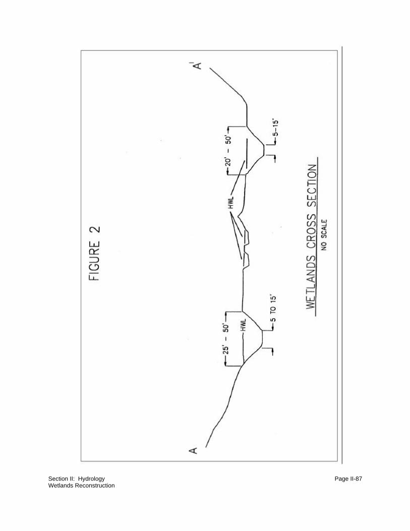
Section II: Hydrology Page II-87Wetlands Reconstruction

Section II: Hydrology Page II-88Wetlands Reconstruction

Section II: Hydrology Page II-89Wetlands Reconstruction
Each dike should have an outlet constructed of paired, rock-filled gabions (see
Figure 4) to permit the slow escape of water from behind the dike. The rock used
to fill the gabions should be competent (e.g. limestone) to assure longevity.
Periodic flows of water will reduce silt accumulations in the gabions, producing an
overall wetlands longevity approximately equal to that of natural stock ponds and
drainage pools
Design planning should ensure minimization of peripheral disturbance to reclaimed
lands. Construction timing is generally limited to the driest seasons. Following
construction, the dike surfaces are seeded to reduce erosion and ensure stability.
Native wheatgrass species are recommended.
(3) Playas
The areas of water concentration in the playa must be small enough to allow water
to collect in sufficient depth (6 to 36 inches). The surface soil must be clayey, or
have a high water table, to allow water to stand on the surface.
(4) Major Drainage Channels
Major drainage channels generally provide the greatest topographic diversity for
construction/installation of such features as deep pools, waterfowl nesting islands,
shallow flats and bars, rock structures, and screened channels. These will assist
in establishment of varying zones of wet meadow, emergent vegetation, and open
water. The guidelines discussed above for establishment of these features in ponds
also apply to their implementation in drainage channels.

Section II: Hydrology Page II-90Wetlands Reconstruction

Section II: Hydrology Page II-91Wetlands Reconstruction
(5) Final Reclamation
The prospective wetland development areas should be broadcast seeded with a
seed mix which will facilitate establishment of wet meadow areas. Select areas
projected to hold seasonal water can then be augmented with emergent wetland
species either through seeding or transplants. The following mix is recommended
to enhance and expedite wet meadow establishment:
Species Rate
Kentucky bluegrass 4.0 PLS pounds per acre
Poa pratensis
Reed canarygrass 4.0 PLS pounds per acre
Phalaris arundinacea
Western wheatgrass 1.0 PLS pounds per acre
Agropyron smithii
A minimum of .5 bulk pounds per acre of at least two of the following species
should also be used:
Prairie cordgrass Spartina pectinata
Streambank wheatgrass Agropyron riparium
Sloughgrass Beckmannia syzigachne
American mannagrass Glyceria grandis
Common rush Juncus effusus
Hardstem bulrush Scirpus maritimus
Cattail Typha latifolia
Prairie coneflower Ratibida columnifera
Yarrow Achillea millefolium
The basic mix can also be augmented with transplants such as spikerush, sedge,
or other wetland species.

Section II: Hydrology Page II-92Wetlands Reconstruction
NOTES

Section II: Hydrology Page II-93Special Considerations in Planning and Constructing Permanent Postmining Impoundments
4. Special Considerations in Planning and Constructing
Permanent Postmining Impoundments
Section editor: Frank K. Ferris Subsection author: Patrick T. Tyrrell
~~~~~~~~~~~~~~~~~~~~~~~~~~~~~~~~~
Situation:
Postmining impoundments are constructed for a variety of reasons. This includes replacement of
pre-existing impoundments and construction of new impoundments, where feasible, to take
advantage of the resulting reduction in backfill replacement movement. Wetland replacement is
another common reason for constructing postmining impoundments. However, wetlands and dam
construction techniques are discussed elsewhere in this section. This subsection will deal more with
the special considerations faced in planning and constructing permanent postmining
impoundments.
Special Considerations:
Function of postmining impoundments will be influenced by water supply and quality, chemical
characteristics of backfill underlying the reservoir basin, and sediment inflow. From a permitting
standpoint, changes in impoundment function or size from premining conditions may trigger a
requirement from the regulatory agency to similarly modify postmining land use descriptions in the
Surface Mine Control and Reclamation Act (SMCRA) permit prior to approval. Under SMCRA,
reservoir feasibility is scrutinized heavily both in design and in performance (via monitoring). If the
impoundment is not a replacement feature, the agency likely will request an alternate reclamation
plan to be implemented if the structure does not function as planned.
Description of Technique:
a. Design and Permitting Considerations
Permanent postmining impoundments are as much a permitting project as a construction
project. Typically, permitting and construction of smaller features, such as stock ponds, are
not as rigorous or costly as similar work for much larger bodies with a capacity of several

Section II: Hydrology Page II-94Special Considerations in Planning and Constructing Permanent Postmining Impoundments
hundred or several thousand acre-feet. These larger impoundments are heavily scrutinized
from the design and performance standpoints.
(1) Uses
Design and permit the impoundment for its anticipated uses. Larger impoundments
intended for wildlife, fish, and recreation, in addition to stock watering, will have
different characteristics than small stock ponds alone. Consult established
guidelines for appropriate reservoir characteristics prior to design, so you and your
management know where you're headed. For waterfowl or fish, for example,
guidelines give recommended percentages for littoral zone (shallows), as well as
deeper water, to make the impoundment more conducive to healthy populations.
(2) Topsoil
Make sure a reasonable and protective topsoil handling plan is put forth. Without
ample topsoil, compliance problems will arise immediately. Typically, for
impoundment drainage areas that are actively disturbed or reclaimed but still
bonded, the reservoir basin should contain no topsoil below the high water line.
This may cause contamination from overland flow.
(3) Water Supply
Permit the impoundment for an expected water supply. Stock ponds can be
permitted to contain the mean annual flood (or some other relatively frequent event,
to keep fresh water available) estimated by modeling. Larger impoundments may
require operational studies to determine a size that will operate properly given the
intended use. Assess such parameters as spilling frequency, range of water level
fluctuations, and possibly a salt (TDS) balance to evaluate water quality over time
and especially during drought periods. These studies will have to take downstream,
senior water rights into account, and may result in construction of a low flow bypass
or other mechanism (or administrative arrangement) to accommodate those rights.
A water right should be obtained for the anticipated capacity of the impoundment;
but remember that, upon construction, the final as-built capacity cannot exceed the
permitted capacity. This is good to know as construction is commencing so no
surprises are encountered. A beautiful pond may never function if insufficient
attention is paid to water supply.
Section II: Hydrology Page II-95Special Considerations in Planning and Constructing Permanent Postmining Impoundments
(4) Freeform Work
As much as possible, leave flexibility in your permitting language to do freeform
work in the field. The freedom to add cost-effective shoreline undulations, small
islands, riprap extensions, or simply keep working if unexpected conditions are
encountered is invaluable if, as a situation arises, you don't have to convene the
legislature to continue. But behave yourself; unlimited flexibility is dangerous when
it reduces reliance on planning.
(5) Reservoir Characteristics
Pay special attention to reservoir characteristics. Safety must be considered
because of the inherent questions about the long-term stability and settlement
characteristics of mine backfill. Impoundments in backfill are more safely operated
if they are totally incised than if they include an embankment sitting on many tens
of feet of uncompacted truck/shovel or dragline spoils. Plus, in the incised case, a
much smaller spillway or overflow channel is needed because there is no
embankment to protect. Be aware of the safety concerns associated with operating
heavy equipment along the banks and shorelines of backfill impoundments as
these will be areas of instability when saturated.
(6) Industrial Uses
Make sure the impoundment is permitted for at least some industrial uses.
Impoundments can be a convenient water storage feature your production
department will want to use, or need to use, at some point. Plus, pit water or
disturbed area runoff can enhance the speed with which the reservoir will fill, if it
is not to be hydraulically connected to its ultimate drainage area for a period of
time. This is a two-edged sword, however. While the extra water can speed
maturation of the impoundment, the mining operation must be careful not to
introduce unwanted sediment or poor quality water into a structure you hope to be
a clean contributor to the postmining environment. Also, the extra water may bias
your evaluation of the water balance for the reservoir, if one is necessary to prove
its ultimate functions.

Section II: Hydrology Page II-96Special Considerations in Planning and Constructing Permanent Postmining Impoundments
b. Construction Considerations
(1) Strip Topsoil
Much work will be going on in the vicinity of the reservoir basin and dam. Because
of this, a first step is to remove all remaining topsoil in the dam, spillway, reservoir
basin, borrow, and access areas.
(2) Work Dry
Working in wet bottomlands generally can be avoided when creating
impoundments in older backfill or small drainages. If you must work in boggy areas,
be cognizant of special sediment control measures that may be needed. Also,
make sure your equipment operator or contractor can handle the work. In tricky
areas, for instance, a floatation dozer may be required. When working in a wet
drainage, coffer dams, a temporary diversion, or pumping will be required to keep
the active areas workable. In ephemeral channels, most water encountered will be
subsurface. A pre-construction borehole grid should awaken you to any potential
construction problems.
(3) Survey Control
Maintain good survey control. This is especially important for the as-built drawings,
spillway and dam crest elevation confirmation, and high water line delineation.
Stake the high water line well in advance of construction to highlight problem areas
that may not have been caught when working from maps or photos (i.e. was a
power line installed recently, or are there trees that can be salvaged?).
(4) Material Sources and Quantities
Permanent impoundments in backfill environments, particularly the larger ones, will
typically require the placement of a layer of "suitable" earth for a specified depth
beneath the reservoir bottom. This is material that meets chemical quality criteria
agreed to in the permitting process. The suitable zone may be four to eight feet in
thickness or more, so a substantial amount must be available. When the time
comes that this material is needed, the source quantity and quality must not be in
question.

Section II: Hydrology Page II-97Special Considerations in Planning and Constructing Permanent Postmining Impoundments
(5) Materials Testing
Do not skimp on materials testing. Since this structure will have to prove its
performance during your bond period, and is intended to last many years beyond,
thorough testing and documentation thereof is critical. Materials testing will include
soil quality (see paragraph D above), compaction, gradation (e.g. for riprap), and
classification (for embankment zones).
(6) Monitoring
Especially for the larger impoundments, provisions should be made during
construction for the water quantity and quality monitoring that will often be required
as a condition of approval. This will include, at a minimum, one or more staff gages,
survey monuments (for the embankment, and for the reservoir basin if constructed
on backfill), and water quality monitoring station locations. Be sure to stash a
johnboat in the brush nearby, if access is unpredictable, to allow for bathymetric
surveys and depth-integrated sampling in the future. If the structure serves any
industrial uses, it will likely end up as an National Pollutant Discharge Elimination
System (NPDES) discharge point. In this case, additional equipment will include a
controlled lower-level discharge (in addition to the service discharge and
emergency spillway) and a flume or other measuring device at the outfall.
(7) Stabilization
Stabilize areas that will see moving water. Spillways, outlet channels, inlet
channels, downwind shorelines, embankments, and mechanical outlet works
should all have erosion protection in place and functional before they are needed.
Especially steep sections, such as in inlets to incised structures and embankment
slopes, will probably require durable riprap. Other areas can adequately be
stabilized with vegetation. To enhance the long term aesthetics and habitat
characteristics of the structure, consider seeding or transplanting wetland
vegetation along shorelines (which should be flatter near the high water line for this
purpose, if possible), although many of these will recruit naturally. Do not plant
trees in embankments, as their root systems may cause destabilization.
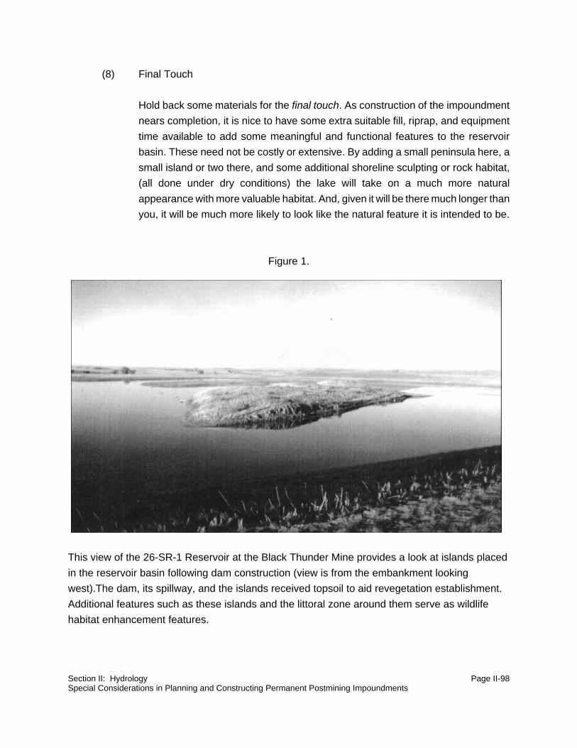
Section II: Hydrology Page II-98Special Considerations in Planning and Constructing Permanent Postmining Impoundments
(8) Final Touch
Hold back some materials for the final touch. As construction of the impoundment
nears completion, it is nice to have some extra suitable fill, riprap, and equipment
time available to add some meaningful and functional features to the reservoir
basin. These need not be costly or extensive. By adding a small peninsula here, a
small island or two there, and some additional shoreline sculpting or rock habitat,
(all done under dry conditions) the lake will take on a much more natural
appearance with more valuable habitat. And, given it will be there much longer than
you, it will be much more likely to look like the natural feature it is intended to be.
Figure 1.
This view of the 26-SR-1 Reservoir at the Black Thunder Mine provides a look at islands placed
in the reservoir basin following dam construction (view is from the embankment looking
west).The dam, its spillway, and the islands received topsoil to aid revegetation establishment.
Additional features such as these islands and the littoral zone around them serve as wildlife
habitat enhancement features.

Section II: Hydrology Page II-99Special Considerations in Planning and Constructing Permanent Postmining Impoundments

Section II: Hydrology Page II-100Special Considerations in Planning and Constructing Permanent Postmining Impoundments

Section II: Hydrology Page II-101
NOTES
Section II: Hydrology Page II-102Hydrologic Control Structure Tolerances
E. Hydrologic Control Structure Tolerances
Section editor: Frank K. Ferris Subsection author: Frank K. Ferris
~~~~~~~~~~~~~~~~~~~~~~~~~~~~~~~~~
Situation:
Implementing a design for a hydrologic control structure often leaves the question of how closely
to adhere to that design. Both carelessness and rigid adherence regarding design can lead to
structure failure. This subsection was developed as a guide for acceptable tolerances.
Critical Considerations:
Lack of experience in a contractor may lead to deficiencies in structure, although excessive
supervision could incur significantly more cost than warranted in the building of the structure.
Outlining acceptable and unacceptable tolerances solves this problem.
Description of Technique:
The tolerances outlined on attached Figures 1 through 7 were developed from field experience and
research of regulations and professional standards. These tolerances were compiled to prevent
repeating past mistakes and to clarify construction standards. They also simplify the certification
process required by most regulatory authorities.
Structure size determines how restrictive these tolerances must be. Tolerances are provided for
various structures. The following figures illustrate tolerances by showing cross sections and
detailing structure component variables:
Figure 1 Spillway Cross Section
Figure 2 Embankment Top Cross Section
Figure 3 Embankment Cross Section
Figure 4 Key Way
Figure 5 Reservoir Dimensions
Figure 6 Diversion Cross Section
Figure 7 Crest Drainage
Figure 8 Reservoir Volume

Section II: Hydrology Page II-103Hydrologic Control Structure Tolerances

Section II: Hydrology Page II-104Hydrologic Control Structure Tolerances

Section II: Hydrology Page II-105Hydrologic Control Structure Tolerances

Section II: Hydrology Page II-106Hydrologic Control Structure Tolerances

Section II: Hydrology Page II-107Hydrologic Control Structure Tolerances

Section II: Hydrology Page II-108Hydrologic Control Structure Tolerances

Section II: Hydrology Page II-109Hydrologic Control Structure Tolerances

Section II: Hydrology Page II-110Hydrologic Control Structure Tolerances

Section II: Hydrology Page II-111
NOTES

Section II: Hydrology Page II-112Surface Water Monitoring Using a Weir
F. Surface Water Monitoring Using a Weir
Section editor: Frank K. Ferris Subsection author: Frank K. Ferris
~~~~~~~~~~~~~~~~~~~~~~~~~~~~~~~~~
Situation:
Surface water monitoring may be required, and can often be difficult to accomplish. A
monitoring site should have long duration and quality construction. The equipment to be used
should likewise be of high quality for reliability and durability.
Special Considerations:
A long-term monitoring site can be difficult to locate, but will be well worth the effort. The
chosen site should remain undisturbed for ten years, or longer if possible, and be located in a
narrow channel area. Short duration data is generally of little value. Construction must be of
good quality to eliminate frequent repairs, which are usually costly, time consuming, and
invalidate data. During large events, backwater may affect weir hydraulics and require an
alternate flow calculation method.
Description of Technique:
Construction of gauge structures generally has been a compound vee-notch weir or Parshall
flume. Parshall flumes have limited capacity and generally cannot handle the peak flows from
draws. The compound vee-notch weir can have whatever capacity is desired. The length of the
compound section determines the capacity. Weirs are usually installed by cutting an open
trench perpendicular to the channel, and placing bolted or welded steel plates (4 foot by 8 foot)
vertically in the trench. It is often difficult to keep the steel level and straight when installing it in
an open ditch. This problem has been solved by using side footings for stabilizing the structure
(see design maps). Adjust the footing location and height, and weir size, as channel capacity
requires.

Section II: Hydrology Page II-113Surface Water Monitoring Using a Weir
For recording the flows, high quality recording equipment should be used to assure continuous
operation during weather extremes. The gauge house equipment records the water level in the
gauge house, which corresponds to the water level at the weir.
Backfill around the weir must be compacted, clayey soil to prevent piping. The weir plate should
be at least five feet into the soil at all locations to prevent water from going under the weir.

Section II: Hydrology Page II-114Surface Water Monitoring Using a Weir
Click here for PDF file of
Hydro\surface water monitoring using a weir

HYDRO/SURFACE WATER MONITORING USING A WEIR

HYDRO/SURFACE WATER MONITORING USING A WEIR (CONTINUED)

Section II: Hydrology Page II-115References
G. References
Barfield, B.J., and S. Albrecht. 1982. Use of a Vegetative Filter Zone to Control Fine Grained
Sediment from Surface Mines. In "Proceedings, 1982 Symposium on Surface mine
Hydrology, Sedimentology and Reclamation." UKY BU 129, pp. 481-490. College of
Engineering, University of Kentucky, Lexington, KY.
Barfield, B. J., and R. C. Warner. 1981. Applied Hydrology and Sedimentology for Disturbed
Areas. Department of Agricultural Engineering. Oklahoma State University, Stillwater,
Oklahoma.
Blodget, J.C., and C.E. McConaughy. 1986. Rock Riprap Design for Protection of Stream
Channels Near Highway Structures, Volume II Evaluation of Riprap Design Procedures.
Water-Resources Investigations Report 86-4128, U.S. Geological Survey, Denver,
Colorado.
Bureau of Reclamation. 1974. Earth Manual. Water Resources Techniques Publication, 2nd
Edition. U.S. Department of Interior, Bureau of Reclamation, Washington, D.C.
Commonwealth of Pennsylvania. 1990. Pennsylvania Erosion and Sediment Pollution Control
Manual. Commonwealth of Pennsylvania, Department of Environmental Resources,
Bureau of Soil and Water Conservation, One Ararat Blvd. Room 214, Harrisburg,
Pennsylvania 17110.
Delisle, G.E., and B.E. Eliason. 1961. Stream Flows Required to Maintain Trout Populations in
the Middle Fork Feather River Canyon. Report No. 2. California Dept. of Fish and
Game, Sacramento, CA.
Dillaha, T.A., R.B. Reneau, S. Mostaghami, and D. Lee. 1989. Vegetative Filter Strips for
Agricultural Nonpoint Source Pollution Control. Trans. Am. Soc. Agric. Eng. 32 (2):513-
519.
Elser, A.A. 1968. Fish Populations of a Trout Stream in Relation to Major Habitat Zones and
Channel Alteration. Transactions, American Fish Society, 97(4):389-97.
Giger, R.D. 1973. Streamflow Requirements of Salmonids. Final Report on Project AFS 62-1,
Oregon Wildlife Commission, Portland, OR.

Section II: Hydrology Page II-116References
Gore, J.A. 1985. The Restoration of Rivers and Streams. Butterworth Publishers, Stoneham,
MA.
Hayes, J.C. and T. Dillaha. 1991. Procedure for the Design of Vegetative Filter Strips. Report
prepared for the USDA-Soil Conservation Service, Washington, DC. Available from J.C.
Hayes, Department of Agricultural and Biological Engineering, Clemson University,
Clemson, SC.
Hayes, J.C., and J. Harrison. 1983. Modeling the Long Term Effectiveness of Vegetative Filters
as Onsite Sediment Controls. Paper 83-2081. American Society of Agricultural
Engineers, St. Joseph, MI.
Linder, C.P. 1969. Channel Improvement and Stabilization Measures, State of Knowledge of
Channel Stabilization in Major Alluvial Rivers. Technical Report No. 7, G.B. Fenwirk, ed.,
Committee on Channel Stabilization, U.S. Army Corps of Engineers.
Mining and Reclamation Council. 1985. Identification of Alternative Sediment Control
Methodologies for Mined Lands. Hess & Fisher, Engineers, Inc., Clearfield,
Pennsylvania.
Parsons, J.E., R.D. Daniels, J.W. Gilliam, and T.A. Dillaha. 1990. Water Quality Impacts of
Vegetative Filter Strips in Riparian Areas. Paper presented at the Winter Meeting of
ASAE, Paper No. 90-2501. St. Joseph, MI.
Peterka, A.J. 1958. Hydaulic Design of Stilling Basins and Energy Dissipators. Engineering
Nomograph No. 25, Technical Information Branch, U.S. Bureau of Reclamation
SCS. 1985. National Engineering Handbook, Section 19, Construction Inspection. U.S.
Department of Agriculture, Soil Conservation Service, Washington, D.C.
SCS. 1984. Engineering Field Manual. U.S. Department of Agriculture, Soil Conservation
Service, Washington, D.C.
SCS. 1947. Handbook of Channel Design for Soil and Water Conservation. SCS-TP-61. U.S.
Department of Agriculture, Soil Conservation Service, Washington, D.C.

Section II: Hydrology Page II-117References
Simons Li & Associates, Inc. 1982. Design Manual for Water Diversions on Surface Mine
Operations. Prepared for the Office of Surface Mining, Contract No. J5101050, U.S.
Department of Interior, Fort Collins, Colorado.
Warner, R.C., and P.J. Schwab. 1992. SEDCAD+ (Sediment, Erosion and Discharge by
Computer Aided Design) Version 3.0. Design Manual. Civil Software Design, Lexington,
Kentucky.

Section II: Hydrology Page II-118Citations
H. Citations
Klingeman, P.C., S.M. Kehe, and Y.A. Owusu. 1984. Streambank Erosion Protection and
Channel Scour Manipulation Using Rockfill Dikes and Gabions. Water Resources
Research Institute, Oregon State University, Corvallis, OR
Wesche, T.A. 1985. Stream Channel Modifications and Reclamation Structures to Enhance
Fish Habitat. Chapter 5 of The Restoration of Rivers and Streams edited by J.A. Gore.
Butterworth Publishers, Stoneham, MA.
SECTION III
TOPOGRAPHY
Section Editor: Robert R. Stowe
table of contents

Section III: Topography Page III-i
TABLE OF CONTENTS
SECTION III: TOPOGRAPHY
A. Introduction . . . . . . . . . . . . . . . . . . . . . . . . . . . . . . . . . . . . . . . . . . . . . . . . . . . . . III-1
B. Hills/Slopes . . . . . . . . . . . . . . . . . . . . . . . . . . . . . . . . . . . . . . . . . . . . . . . . . . . . . III-3
1. Hillslope Shaping and Morphology . . . . . . . . . . . . . . . . . . . . . . . . . . . . . . . III-3
2. Backfill Grading Observations . . . . . . . . . . . . . . . . . . . . . . . . . . . . . . . . . III-13
3. Evaluation and Comparison
of Topographic Descriptive Methods . . . . . . . . . . . . . . . . . . . . . . . . . . . . III-19
C. References . . . . . . . . . . . . . . . . . . . . . . . . . . . . . . . . . . . . . . . . . . . . . . . . . . . . III-25

Section III: Topography Page III-ii
NOTES

Section III: Topography Page III-1Introduction
A. Introduction
Section editor: Robert R. Stowe
~~~~~~~~~~~~~~~~~~~~~~~~~~~~~~~~~
Reclamation of western lands can be enhanced with some forethought as to what the topography
will look like and how it will function with the proposed postmining land use. When land is being
reclaimed from surface mining back into grazing land and/or wildlife usage, adding some macro-
and micro-relief structures can be of benefit to both livestock and wildlife. Semi-arid conditions
frequently mean few or no trees and strong winds. When there is little or no topographic relief to
protect livestock and wildlife from the summer sun and the winter winds, animals suffer and may
perish. Topographic relief can provide the protection required in addition to augmenting the
postmining land use.
In areas where reclaimed lands will become farm land, topographic design is also important. In
these situations, minor hills and slopes, as well as drainages, should be designed so that runoff
from precipitation and snow melt will not inundate land to be farmed, and the reconstructed
drainage-ways will not be overly erosive.
The following subsections discuss methods of shaping hillslopes in order to provide topographic
diversity for wildlife and livestock while minimizing erosional features. A discussion of procedures
used to compare the premining and postmining slope regime is also included.

Section III: Topography Page III-2
NOTES

Section III: Topography Page III-3Hillslope Shaping and Morphology
B. Hills/Slopes
1. Hillslope Shaping and Morphology
Section editor: Robert R. Stowe Subsection authors: Christopher D. Lidstone/C. Marty Jones
~~~~~~~~~~~~~~~~~~~~~~~~~~~~~~~~~
Situation:
Landform stability is a critical element in the reclamation of mined lands. The hillslope is the
uppermost unit of the basin watershed and is typically responsible for the production of sediment
to the watershed. Concentrated flow or flowing water transfers this sediment to the first and
second order stream channels and ultimately delivers the sediment to receiving waters outside the
mine permit area. Where surface runoff remains in an unconcentrated condition, little sediment
movement and virtually no transfer of sediment off-site will occur.
The intent of mining regulations is to minimize sediment production off mined and reclaimed lands,
and to reestablish a hydrologic system which will behave in an erosionally stable manner equal to
or better than that which existed prior to mining.
For the purposes of this handbook, the hillslope component of reclaimed basins is the upper
watershed and valley sideslopes which deliver runoff to the smallest (first order) designed
drainages in the reclamation plan. Where slope gradients or slope length exceeds some threshold
value, surface water runoff will concentrate, producing rill and gully erosion. Hillslope shaping, and
an understanding of slope morphology and processes, will reduce surface erosion on the hillslope.
Special Considerations:
Decisions regarding landform shaping reflect a balance of mine path, mining methods, geomorphic
considerations, and economics. The operator must consider the locations and elevations of
haulage roads, ramps, spoil piles, pre-existing and postmining basin outfalls and drainage divides.
For example, mine production features such as haulage ramps and roads can often become
components of the postmining drainage system. In these areas, backfill costs can be curtailed if
postmining drainages are restored to incorporate a portion of the ramp or road alignment.

Section III: Topography Page III-4Hillslope Shaping and Morphology
TOP ORINTERFLUVE SHOULDER ARM TOE
HILLSLOPE COMPONENTS
EL
EV
AT
ION
IN
CR
EA
SE
S
DISTANCE FROM TOP OF SLOPE
CLOMPLEX
SLOPE
PROFILE
DRAINAGEARE
HENCERUNOFF INCREASE
Figure 1. Hillslope Components
(From Perrens, et. al., 1984)

Section III: Topography Page III-5Hillslope Shaping and Morphology
Similarly, out-of-pit overburden stockpiles and/or dragline spoil dumps can be formed into the upper
elevation or hillslope component of the drainage system. In doing this, the operator can minimize
"double handling" and reduce hauling costs. Pit backfill sequencing should incorporate the final
reclamation topography and address not only final drainage design but also final hillslope design.
The overall reclamation plan and hillslope design must reflect such critical variables as postmining
basin outfalls and the topography of adjacent lands. Reclamation planning should consider basin
or hillslope aspect. Final topography can be adjusted to accommodate the harsher conditions
associated with increased solar and wind exposure. Experience suggests that there is a significant
im
provement in reclamation success on protected slopes. Increased moisture retention is required
on southern exposure slopes. This can be accomplished by flatter slope angles and a more
roughened final reclamation surface.
Description of Technique:
a. Hillslope
The hillslope is defined by a minimum of four subunits and the standard nomenclature (after
Perrens, et.al. 1984) is presented on Figure 1. These particular units were first developed
by agronomists in recognition of the importance of a soil's position on a natural hillslope with
respect to soil genesis. Those soils, which develop near the shoulder and arm of the slope,
are transported by both water and gravitational processes to the toe of the slope. In nature,
soil horizons are thickest at the toe of the slope and thinnest at the shoulder.
When replacing topsoil on a reclaimed hillslope, it is typically replaced to a uniform depth.
As natural erosion and depositional processes occur on the reclaimed hillslope,
translocation of topsoil will take place and over time, the thicker zones will occur at the toe
of the slope. Recognizing that these processes will occur, yet designing the slope to
minimize the movement of topsoil by such accelerated processes as rill and gully erosion,
is a critical design consideration.
The design philosophy should recognize the value of rainfall infiltration and the liability of
direct surface runoff. Water retention on the hillslope will promote revegetation success,
and by so doing will stabilize the reclaimed land surface. Where runoff occurs in a
concentrated manner, excessive shear forces may occur, resulting in rill and gully erosion.
Minimizing slope length and excessive slope gradients will prevent the concentration of
direct surface runoff on the hillslope.

Section III: Topography Page III-6Hillslope Shaping and Morphology
Design and construction considerations, which should be addressed in hillslope
reclamation, are addressed in the following paragraphs.
(1) Hilltop or Interfluve
As a rule of thumb, the designer should maximize the acreage of the hilltop and
minimize the overall slope length. The hilltop should be formed to retain the
maximum moisture onsite with minimum delivery of runoff from the hillslope. In the
field, this translates as grade staking the top of an overburden stockpile or dragline
dump to ensure the flattest possible configuration (20H:1V or flatter) while
maintaining an overall positive drainage. Leaving the regraded surface in a
roughened condition will enhance its water retention capabilities. Immediately prior
to the replacement of the topsoil, the overburden should be "deep-ripped" or
scarified. The topsoil can be replaced directly on the rough overburden backfill
surface (at variable thicknesses) and/or the replaced topsoil can be manipulated
by mechanical farming methods. Reclamation success has been achieved with
"pitting", which is a mechanical means of constructing actual soil pits or divots
within the topsoiled surface. Pitting is accomplished simultaneously with drill
seeding during final reclamation. Similarly, the construction of small intermittent
dozer basins has successfully achieved the water retention goals and aided in the
development of small playa-like features.
Where a greater acreage of interior drainage is required or desired, the
replacement of well-drained soils is essential to prevent the unwanted accumulation
of salts. Although natural playas and interior drainage features exhibit a
predominance of clay soils, the elimination of salt accumulation will enhance
revegetation efforts during the critical initial years of bond release. More
information regarding topsoil replacement can be found in the Topsoil section of
this handbook.
A final consideration in the geometry of the hilltop is an assessment of contributing
basin area for the receiving drainages. Basin divides can be manipulated to
increase the watershed area and peak flow hydrology of one basin while
decreasing the watershed area and peak flow hydrology of the adjacent basin. If
channel slopes are excessive in one basin, the designer might consider diverting
part of the basin runoff to another basin, thereby decreasing the overall peak flow
hydrology of that basin.
(2) Hillslope: Shoulder and Arm of Slope

Section III: Topography Page III-7Hillslope Shaping and Morphology
To the extent possible, the designer should minimize the length of slope or reduce
the slope steepness. Initial slopes on mine dumps typically range from angles of
repose to 1.5H:1V. Minimum reclamation slopes are often controlled by equipment
accessibility and the ability to "farm along the contour". Although minimum
"farmable slopes" may range from 2.5H:1V to 3H:1V and are dependent on the
farming equipment, vegetative success is more pronounced on 4H:1V or shallower
slopes. Within arid and semi-arid reclamation, slope aspect plays an important part
in vegetation success and 5H:1V or flatter minimums are found to be more
successful on south aspect slopes. North-facing slopes can be slightly steepened
and 4H:1V minimums have proven to be successful. Wherever possible, flatter
slope gradients are highly recommended and will increase rainfall infiltration and
decrease concentrated flow.
Slope length and slope shape are also critical design considerations. The slope
shape and slope transitions should be designed to promote unconcentrated flow
and to minimize the offslope delivery of sediment. Where the combination of
critical slope characteristics (slope length, slope steepness and contributing area)
will result in concentrated flow, the runoff and sediment should be collected into a
first order channel and delivered in a controlled manner offslope. Small drainage
reconstruction is discussed in the Hydrology section of this handbook.
Practical experience has shown that slope lengths in excess of 50 to 100 feet at
gradients of 4H:1V or steeper may result in rill and gully erosion. At 5H:1V slopes,
lengths in excess of 150 feet or more may be problematical. Of course, vegetation
density, soil type, and storm intensity and distribution are important variables in this
analysis. Coarse textured soils and/or successfully vegetated slopes will allow
more latitude in slope length.
Cross-slope ditches or furrows can be incorporated into the hillslope reclamation
to achieve the required slope lengths. Such ditches should be small and
unobtrusive and should be constructed oblique to the contour.
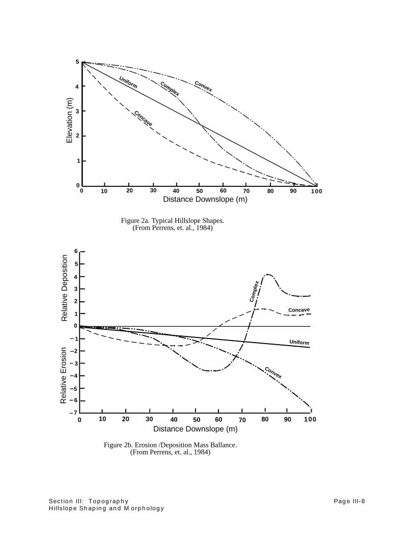
Section III: Topography Page III-8Hillslope Shaping and Morphology
Concave
Complex
Uniform
Distance Downslope (m)
Ele
vatio
n (m
)
1
2
3
4
0
5
0 10 20 30 40 50 60 70 80 90 100
Figure 2a. Typical Hillslope Shapes.(From Perrens, et. al., 1984)
1
2
3
4
0
5
6
1
2
3
4
5
6
70 10 20 30 40 50 60 70 80 90 100
Distance Downslope (m)
Rel
ativ
e E
rosi
onR
elat
ive
Dep
ositi
on
Figure 2b. Erosion /Deposition Mass Ballance.(From Perrens, et. al., 1984)
Convex
Convex
Uniform
Concave
Com
plex

Section III: Topography Page III-9Hillslope Shaping and Morphology
In order to reduce the probability of ditch failure, a minimum gradient of four
percent should be established for all cross-slope ditches. Flatter ditch slopes and
contour ditches are difficult to construct, and tend to collect water in low spots
created by settlement of the fill or poor staking/construction practices.
Figures 2a and 2b present typical hillslope shapes and a mass balance of erosion
and deposition along the hillslope. The movement of sediment within the hillslope
component is a function of both water and gravitational processes. From a
practical standpoint, uniform and concave slopes are most often employed in mined
land reclamation. Of these two slopes, the concave slope provides a more stable
land surface as seen in Figure 2b. Complex slopes, which are more readily found
in nature, exhibit increased erosion along the center or medial portion of the slope
and increased deposition at the toe of the slope. If designed properly, a complex
slope can be a stable entity within the overall reclamation scheme and provide
diversity in the overall reclamation topography.
Uniform slopes are the easiest to stake and construct in the field. The slope
configuration provides few depositional sites within the hillslope. However, where
excessive slope lengths occur, offslope transport of sediment (erosion) can be
anticipated (Figure 2b). Where uniform slopes are staked in the field, flatter
gradients and adequate transitions at the toe must be incorporated. Figure 3a
presents a 4H:1V uniform slope. Depending on slope length, basin aspect, and
transition requirements, a flatter slope such as a 5H:1V or 6H:1V may be
recommended.
Concave slopes may require additional staking and construction supervision, but
provide better control of sediment movement and a more stable land surface
(Figure 2b). The lower gradient portion of the slope allows water velocities to
decrease, thereby enhancing depositional processes. The increased staking and
construction supervision responsibilities may offset long term maintenance
responsibilities. A variation of the concave slope might entail a 4H:1V slope from
the interfluve to the arm of the slope and a 5H:1V slope from the arm through the
toe section of the slope. Practically speaking, in a multiple-benched mine dump,
the upper lifts would be graded to a 4H:1V slope. The cut material would be
relocated to the base of the dump and the 5H:1V toe slope would be created
(Figure 3b). The point of inflection between the 4H:1V and 5H:1V slope
(intermediate catch point) would be established based on an earthwork balance.

Section III: Topography Page III-10Hillslope Shaping and Morphology
Complex slopes require intermediate cut stakes as well as the staking of each
catch point (Figure 3c). Typically the construction of a complex slope may require
additional earthwork, although there will be certain earthwork savings in the steep
upper "shoulder" reach. The upper reaches of a complex slope provide maximum
surface area for rainfall infiltration and minimum runoff. The arm of the slope is the
steepest portion of the slope, yet will have limited drainage area contributing to
direct surface runoff. Where runoff does occur, the hillslope gradients are the most
gentle and velocities will be reduced.
(3) Hillslope: Toe of Slope
The construction of the toe of the slope is often the most essential aspect in
hillslope reclamation. Too often the toe of the slope will be left in a convex or over-
steepened form. This condition will often result in erosion, since the hillslope
drainage basin area is the greatest at the toe of the slope. Because runoff
increases with increased drainage area (Figure 1), it is essential that the slope
gradient decreases at the toe of the slope. As noted in the previous sections, it is
the design intent to maintain unconcentrated flow and promote infiltration. The
lower gradients will also promote the deposition of hillslope sediment, thereby
reducing sediment contribution to receiving drainages.
A second element in the construction of the toe of the slope is the smooth transition
of the hillslope into the adjacent reclamation valley. A low gradient toe, which
transitions into a stream valley, will allow lateral movement of a reclamation
channel against the hillslope. If the slope enters the stream valley in an over-
steepened condition, erosion and undercutting of the toe is likely to occur.
b. Summary of Hillslope Morphology
Hillslope design should maximize the opportunity for rainfall infiltration and minimize the
opportunity for surface water runoff and flow concentration. The movement of sediment
within the hillslope form is an essential geomorphic element in natural slope processes.
Minimizing offslope movement via rill and gully erosion is critical, and will result in a
reduction in sediment contribution to the receiving drainages.
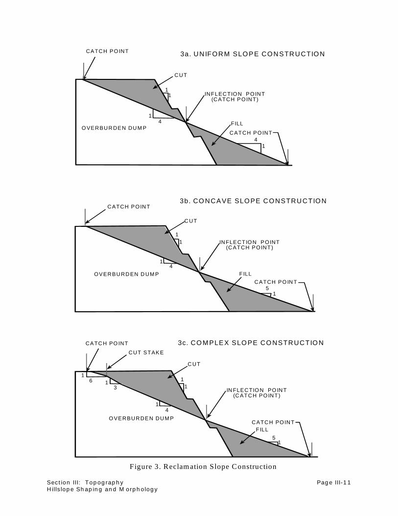
Section III: Topography Page III-11Hillslope Shaping and Morphology
3a. UN IFORM SLO PE CO NSTRUCTIO NCATCH POINT
CUT
INFLECTION POINT(CATCH POINT)
CATCH POINT
FILLO VERBUR DEN DUM P
11
1
1
4
4
3b. CO NCAVE SLO PE CO NSTRUCTIO NCATCH POINT
C UT
IN FLECTION POINT(CATCH POINT)
CATCH PO IN T
FILLOVERBURD EN D UM P
11
1
1
4
5
3c. CO M PLEX SLO PE CO NSTRUCTIO NCATC H PO INT
C UT
IN FLECTIO N PO INT(C ATCH POINT)
CATCH POINTFILL
O VERBURDEN DUM P
11
1
1
4
5
CUT STAKE
11
36
Figure 3. Reclam ation Slope Construction

Section III: Topography Page III-12Hillslope Shaping and Morphology
Figure 3 presents the three slope shapes discussed above and the minimum construction
staking requirements. Although all three slope shapes are presented, the concave slope
design best balances the economics of material movement with the design philosophy
discussed above.
c. Construction Practices
Construction requirements are relatively simple and much work can be completed with a
dozer. If dozers are used in construction, catch points should be staked in the field and
adequate compaction is required near the toe. If scrapers are used in construction,
additional staking to define cuts may be helpful.
Some compaction of the fill portion of the hillslope is essential to prevent or eliminate
settlement, and in some cases failure of the fill. Concern with compaction is not as
pronounced when construction by scrapers is employed. When backsloping a fill against
a highwall, keying the fill into the rock highwall must be addressed. In certain instances
where ground water is encountered, drainage below the fill must also be incorporated into
the design.

Section III: Topography Page III-13Backfill Grading Observations
2. Backfill Grading Observations
Section editor: Robert R. Stowe Subsection author: Frank K. Ferris
~~~~~~~~~~~~~~~~~~~~~~~~~~~~~~~~~
Situation:
Relief techniques are an important tool in controlling erosion and cost. Planning a water course
for drainage will facilitate preparation for the flow and reduction of erosional problems on reclaimed
lands.
Costs can be controlled by planning for the placement of backfill and having the backfill dumped
to grade as much as possible. The incremental haulage or handling cost of $ 0.05 per yard is very
economical compared to the $ 0.25 to $ 0.50 per yard cost of rehandling backfill.
Special Considerations:
Backfill will differentially settle, up to ten feet on a rare occasion; three feet is not unusual.
Constructed topography features must be massive enough to function even with settling in critical
areas. Plan ahead to know your desired topography. This will allow for maximum use of mine
equipment for placing and grading backfill while that equipment is in the area. Finish grading of
frozen backfill will likely take two to three times the equipment hours as compared to thawed
backfill.
Description of Technique:
a. Dump Slope Grading
Dump grading can be made more economical by the selective placement of loose dumps
and through dump grade control (see Figure 1). Dump grading volume can be reduced and
maintained by using the following methods:
(1) Decreasing the dump height by five to seven feet (loose dump height).

Section III: Topography Page III-14Backfill Grading Observations
BE
FO
RE
WIT
H L
OO
SE
DU
MP
S
AF
TE
R G
RA
DIN
G
LOO
SE
DU
MP
S
FIG
UR
E 1
NO
SC
ALE

Section III: Topography Page III-15Backfill Grading Observations
(2) Sloping the dump grade to be lower at edges and high where needed.
(3) Placing loose dumps at the toe area, dump top, and ridge spots to reduce dozing
needs and create micro-features and drainage control.
b. Second Bench
A second bench reduces reclamation grading volume by 70 percent (see Figure 2). In this
case, the volume was reduced from 48 yards3 to 14 yards3 per linear foot of dump face with
a 50 percent reduction in push length.
The second bench can be built between or after the main dump. However, if it is built first,
it will reduce the overall cycle time of the haul trucks because they will not have to climb to
the top to dump all loads of dirt. After the lower dump is in place, the toe limits of the
second (top) dump are established on the second bench. Note that additional activity is
required by a dump dozer during backfilling.
c. Dump Top Reclamation
For more information, see part a(3) in the subsection entitled "Small Drainage Waterway
Construction" in the Hydrology section of this handbook.
It is extremely important to limit the flat areas above slopes because concentrations of
runoff down the slope will cause slope erosion. Generally there are two options, depending
upon the width of the dump:
(1) Grade to a hill (see Figure 3)
(2) Grade to a hill with interior drainage (see Figure 3)
d. Long Slope Grading
For information on Long Slope Grading, please see part a(1) in the subsection entitled
"Small Drainage Waterway Construction" in the Hydrology section of this handbook.

Section III: Topography Page III-16Backfill Grading Observations
1.5
1
TO
TA
L O
F 3
86.5
5 S
q. F
t. D
OZ
ED
143.
1 S
q.F
tD
OZ
ED
AR
EA
.24
3.45
Sq.
Ft.
DO
ZE
D A
RE
A
45'
LOO
SE
DU
MP
S 5
' HIG
H W
ITH
A 5
:1 S
LOP
E
SC
ALE
= 1"
=20
"13
03 S
q.F
t.D
OZ
ED
AR
EA
50'
FIG
UR
E 2
SC
ALE
= 1"
=20"
22.8
313
03 S
q.F
t.
148.
4
51
1.5
16.
51
6.5
1
1.5
11
5

Section III: Topography Page III-17Backfill Grading Observations
FIG
UR
E 3
NO
SC
ALE
1
15
1.5
11.
55
1
51 1
1.5
1
1
6–7
6–7
LOO
SE
DU
MP
S
LOO
SE
DU
MP
S
6–7
1
1.5
1
16–7
15

Section III: Topography Page III-18
NOTES

Section III: Topography Page III-19Evaluation and Comparison of Topographic Descriptive Methods
3. Evaluation and Comparison
of Topographic Descriptive Methods
Section editor: Robert R. Stowe Subsection author: Robert R. Stowe
~~~~~~~~~~~~~~~~~~~~~~~~~~~~~~~~~
Situation:
Mining reclamation requires a comparison between the premining and postmining slopes. This
comparison is done to ensure the support of postmining land use. Reconstructed land must blend
with native land and postmining slopes must be neither much steeper nor much flatter than original
slopes.
Special Considerations:
These slope comparisons generally divide the land surface into a number of grid cells in order to
calculate the slope, or rise divided by run, at the grid cell node. This information can then be
mapped in several ways. Three methods for evaluating and comparing topography techniques are
outlined below.
Description of Technique:
a. Evaluation and Comparison of Topography Techniques
From any of the following three techniques, tables and histograms can be generated to
evaluate the percentage of topographic surface with certain slopes or features. Tables and
histograms are especially useful when comparing two surfaces, for example premining and
postmining topography. Many engineering firms are available to conduct these evaluations.
Special engineering software packages are also available to do this work.
(1) Elevations
Slope value (and optionally, direction which yields a vector) must first be plotted for
each grid node. The nodes for the grid and search radius should be selected so
that averaging or smoothing between nodes conceals variability in the underlying
topography. In one particular form of this method, slopes are calculated by first

Section III: Topography Page III-20Evaluation and Comparison of Topographic Descriptive Methods
estimating elevation values into a 100-foot grid from irregular contour data. These
grid values are then subtracted from the nearest neighbor to provide a change in
elevation in each cardinal direction. Elevation differences in north and south
directions are added, then divided by the total difference between grid values (i.e.
200 feet), to provide a slope in the north-south direction. The same is done for the
east-west direction. These component slopes are then added, via vector analysis,
to yield the slope magnitude in percent and direction in degrees at the node being
analyzed. Vectors may be drawn from each node pointing downslope, with the
length of the vector denoting the steepness of the slope.
The above analysis is performed every 300 feet to separate posted data values
sufficiently for plotting purposes (postmining values at a 100-foot spacing would
require a very large map with no gain in accuracy or precision). Slope isopleths
may be drawn by contouring the slope magnitude from the slope data on 300-foot
centers. Slopes are calculated within projected disturbance limits only, and both
pre- and post-mining slopes are calculated on identical 300-foot centers to allow
direct comparisons. These values are then posted on a screened topo base map
(see Figure 1). This dynamic map can provide insights as to what areas may
become erosive and where deposition is likely to occur in a drainage.
(2) Isopleth Map
A second method is to contour the points of equal slope in an isopleth map. The
contours on this map show the areas of increasing or decreasing slope. A plain
with little relief would show few isoslope contours, whereas a quickly steepening
bluff would be depicted by many isoslope contours. Water will flow perpendicular
to the isoslope contour lines. This is illustrated in Figure 2.
(3) Mapping Geomorphic Features
A third method of evaluating topography techniques is to map geomorphic
features, such as hills, slopes, ridges, saddles, valleys, and scarps on a topo
base. This map will show areas where the various geomorphic features are
located. Materials used to identify geomorphic features include a premining
topographic map of scale 1"=1000' and numerous composite air photographs.
Abandoned meanders shown on the premining landforms map are identified
using USGS topographic maps of 1"=2000'. Meanders shown are those that
were apparent on more than one map source and appear to be within the limits

Section III: Topography Page III-21Evaluation and Comparison of Topographic Descriptive Methods
of the most recent terrace deposits. This is more of a qualitative map than either
of the two previous maps, as seen in Figure 3.

Section III: Topography Page III-22Evaluation and Comparison of Topographic Descriptive Methods
FIGURE 1
6
9
8
8
22
2
2
7
9
9
27 2634 354 4
45
45
5
7
7
7 7 15
3013
9
4565
16
3 0
533
321981616
5
01
3
4
4
7
29
7
8
88 8
4
4
4
4
5
5
3
3
3
6
6
6
0 12
12
12
3
3
3
888
11
11 11
11
6
10
4
7 7 6 6 6 7

Section III: Topography Page III-23Evaluation and Comparison of Topographic Descriptive Methods
FIGURE 2

Section III: Topography Page III-24Evaluation and Comparison of Topographic Descriptive Methods
352627
34
LEGEND
KNOB ACREAGE
PLAYA ACREAGE
SCARP
RIDGE ACREAGE
FIGURE 3

Section III: Topography Page III-25References
C. References
Perrens, S.J., G.R. Foster, D.B. Beasley. 1984. "Erosion's Effect on Productivity Along Non-
Uniform Slopes" In: Erosion and Soil Productivity; Proceedings of the National Symposium
on Erosion and Soil Productivity; December 10-11, 1984 (New Orleans, LA). ASAE
Publication 8-85. American Society of Agricultural Engineers, St. Joseph, Michigan.

Section III: Topography Page III-26
NOTES

SECTION IV
WILDLIFE MITIGATIONAND PROTECTION
table of contents

Section IV: Wildlife Mitigation and Protection Page IV-i
TABLE OF CONTENTSSECTION IV: WILDLIFE MITIGATION AND PROTECTION
A. Introduction . . . . . . . . . . . . . . . . . . . . . . . . . . . . . . . . . . . . . . . . . . . . . . . . . . . . . IV-1B. Practices During Mining . . . . . . . . . . . . . . . . . . . . . . . . . . . . . . . . . . . . . . . . . . . . IV-3
1. Fencing Practices and Wildlife . . . . . . . . . . . . . . . . . . . . . . . . . . . . . . . . . . IV-32. Reducing Powerline Hazards to Wildlife . . . . . . . . . . . . . . . . . . . . . . . . . . . IV-73. Traffic and Roadways . . . . . . . . . . . . . . . . . . . . . . . . . . . . . . . . . . . . . . . IV-134. Providing Interim Wildlife Habitat . . . . . . . . . . . . . . . . . . . . . . . . . . . . . . . IV-155. Raptor Nest Relocation . . . . . . . . . . . . . . . . . . . . . . . . . . . . . . . . . . . . . . . IV-256. Animal Control . . . . . . . . . . . . . . . . . . . . . . . . . . . . . . . . . . . . . . . . . . . . . IV-27
C. References . . . . . . . . . . . . . . . . . . . . . . . . . . . . . . . . . . . . . . . . . . . . . . . . . . . . IV-37

Section IV: Wildlife Mitigation and Protection Page IV-ii
NOTES
Section IV: Wildlife Mitigation and Protection Page IV-1Introduction
A. Introduction
Section editor: Bonnie C. Postovit
~~~~~~~~~~~~~~~~~~~~~~~~~~~~~~~~~
Like soil, water, and vegetation, wildlife is a resource that must be protected from undue impact
during mining. Soil and water are the basic resources that support vegetation; water and vegetation
maintain wildlife. I view wildlife as an indicator of the health of the entire resource system. Robust,
diverse wildlife populations are a sign that the supporting resources are functioning together
properly.
Although the response of wildlife to mining ultimately depends upon the management of soil, water,
and vegetation, this section of the manual outlines specialized mitigation measures that apply
directly to wildlife. Subsections on fencing, powerlines, and roadways examine techniques to modify
the impact of those aspects of mine development. Another subsection details ways to provide
habitat for wildlife during the mining process. A separate subsection deals with raptor nest
relocation; a mitigation measure developed in response to Federal laws that protect raptors and
their nests, eggs, and young. The final subsection, on animal control, describes management
strategies to use when wildlife interfere with mine operations or reclamation.
For many people, wildlife defines the West. How industry treats this high-profile resource during
mining and reclamation will, to a great extent, color the public's attitude toward energy and mineral
extraction.

Section IV: Wildlife Mitigation and Protection Page IV-2
NOTES
Section IV: Wildlife Mitigation and Protection Page IV-3Fencing Practices and Wildlife
B. Practices During Mining
1. Fencing Practices and Wildlife
Section editor: Bonnie C. Postovit Subsection author: Bonnie C. Postovit
~~~~~~~~~~~~~~~~~~~~~~~~~~~~~~~~~
Situation:
Fencing is necessary to prevent animals from entering hazardous areas, and may be needed to
temporarily protect reclaimed areas.
Special Considerations:
Fences should be constructed and located to present the least possible hazard to free-ranging
wildlife. Pronghorn are not willing or skilled jumpers, and where possible prefer to go under fences
rather than over. Large-scale mortalities can occur when herd movements are blocked during
severe weather, causing pile-ups and starvation. Smaller-scale mortality occurs when pronghorn
become entangled while jumping over fences. Deer jump fences readily; however they sometimes
entangle their hind legs in the top two strands of a barbed wire fence. Fawns, especially, are prone
to entanglement.
Description of Technique:
a. Selective Exclusion
The following text briefly describes fencing considerations and general design dimensions
for excluding various animals. A thorough discussion of fencing and fence design may be
found in Wyoming Department of Environmental Quality - Land Quality Division (WDEQ-
LQD) Guideline 10 (WDEQ-LQD, 1979).

Section IV: Wildlife Mitigation and Protection Page IV-4Fencing Practices and Wildlife
(1) Excluding Livestock and Pronghorn
Prohibiting livestock and pronghorn access can be accomplished with a four foot
high "sheep-tight" fence. Such a fence is usually constructed of woven wire topped
by two strands of barbed wire.
Because blocking pronghorn herd movements can cause significant mortality, the
amount of land fenced in this manner should be limited. Such a fence may be
necessary in the immediate vicinity of pits and operations areas to keep livestock
and pronghorn from the hazards of highwalls and heavy traffic. It is not generally
necessary to exclude deer from such areas, as they typically negotiate such
hazards readily.
(2) Excluding Livestock and All Big Game
Prohibiting livestock, deer, elk, and pronghorn access can be accomplished with a
seven to eight foot woven wire fence. Alternatively, a six foot woven wire fence can
be topped with two strands of barbed wire. Such a fence may be needed if all
grazing is to be excluded from an area. Where deer (or elk) are present, such a
fence may be necessary to keep game animals from entering hazardous areas or
to temporarily protect vegetation.
(3) Excluding Livestock Only
Prohibiting livestock, but not wildlife, access can be accomplished with a three- or
four-strand wire fence. Such a fence can be used to control livestock within an area,
but allow relatively free range by wildlife. The following dimensions are
recommended by the Bureau of Land Management, and may be found in the
publication "Proceedings: Regional Fencing Workshop" (BLM, 1974). To exclude
cattle, a 44-inch, three-strand wire fence is sufficient. For excluding sheep, a 38-
inch, four-strand fence can be used. If both are present, a 44-inch, four-strand
fence is necessary.
On any such fences, a smooth bottom wire allows pronghorn to go under easily. On
cattle-tight fences, this wire can be placed 16 inches above the ground. For sheep-
tight fences the wire should be only 10 inches high.

Section IV: Wildlife Mitigation and Protection Page IV-5Fencing Practices and Wildlife
Where deer cross these fences, using a smooth top wire, and placing twisted wire
stays at the midpoint between fence posts to keep wires separated, may help
decrease deaths from entanglement.
b. Avoiding Wildlife Hazards
Avoiding hazards to wildlife is important in fence location and design. Where large areas
must be fenced, it is necessary to plan for safe and easy animal movement.
(1) Create Passages
Create passages where major herd movements may be blocked. Deer are known
to use underpasses and "deer gates", but pronghorn will not. Antelope passes can
be created by installing cattle-guard-type structures. Rather than relying on
specialized structures, it is better to use a fence design that permits wildlife
movement under or over.
(2) Eliminate Sharp Corners
Eliminate 90° corners where animals are found to "pile up" during mass movement.
Construct shallower angles where a fence must turn or narrow down.

Section IV: Wildlife Mitigation and Protection Page IV-6
NOTES

Section IV: Wildlife Mitigation and Protection Page IV-7Reducing Powerline Hazards to Wildlife
2. Reducing Powerline Hazards to Wildlife
Section editor: Bonnie C. Postovit Subsection author: Howard R. Postovit
~~~~~~~~~~~~~~~~~~~~~~~~~~~~~~~~~
Situation:
Powerlines present an electrocution hazard to raptors (birds of prey) and other large birds, such
as herons. Raptors and other birds are protected by Federal law. Proper design of powerlines can
minimize or eliminate electrocution and other hazards.
Special Considerations:
Power poles provide attractive perch, nest, and roost sites, especially in relatively flat and treeless
areas. This is a positive impact of powerline construction. However, the size of some birds makes
it possible for them to simultaneously contact two charged objects (phases or conductors) or one
charged object and a ground wire. Most problems occur on distribution lines, particularly at junction
poles and transformers. New lines can be constructed to raptor-safe specifications, and older lines
can be modified if an electrocution problem arises.
Description of Technique:
a. Design Strategies
High voltage transmission line towers or H-frames seldom pose an electrocution hazard
because of the distance between the phases. However, H-frames can be detrimental to
raptor populations because these structures commonly attract nesting raptors, but offer no
substantial support for a nest. Nests built on H-frames are regularly destroyed by wind
during the breeding season, resulting in loss of eggs or young.
Raptor-safe designs for power poles and lines have been developed through cooperative
research between power companies, government agencies, conservation organizations,
and private consultants. The resulting designs all but eliminate the possibility of
electrocution. The most complete manual on this work is: "Suggested practices for raptor

Section IV: Wildlife Mitigation and Protection Page IV-8Reducing Powerline Hazards to Wildlife
protection on power lines--state of the art in 1981" (R. R. Olendorff et al., 1981). When
contracting powerline construction for an operation, it is important to specify that lines be
of a "raptor-safe" design. Power companies and electrical contractors should be familiar
with the Olendorff et al. publication.
b. Modification Strategies
Modification strategies can take one of four forms: separation of phases, insulation, perch
management, and nest management. It is generally not necessary to modify all poles of an
existing line. Any poles where electrocution has occurred should be modified to prevent
further losses. Other non-safe poles (particularly junction or transformer poles) showing
signs of regular raptor use (whitewash or pellets on the ground below) could also be
modified to eliminate the potential for electrocution. Poles or H-frames where repeated
unsuccessful nesting attempts are documented can be modified to prevent or enhance
nesting.
(1) Separation of Charged Phases
A 152-centimeter (60-inch) separation of charged phases is considered necessary
to prevent electrocution of birds the size of golden eagles (see Figure 1 - figures at
end of text). Separation on a 3-phase line can be accomplished by raising the
center line, or lowering the cross-arm that bears the outer two lines. When proximity
of a charged part and a ground wire is the problem, a gap can be cut in the ground
wire. (See Olendorff et al., 1981.)
(2) Insulation
While reconfiguring existing poles can be very expensive, insulating is relatively
cheap and simple. Covering jumper wires with rubber "squirrel wrap" (see Figure
1) has been effective in reducing electrocutions at junction poles. The same
strategy can be applied to wires on transformers. On problem line poles, insulation
can be extended one meter from the pole along all phases (see Figure 1).
(3) Perch Management
If neither separation of phases nor insulation are feasible, a pole can be modified
to prevent birds from perching or nesting between wires on cross-arms (see Figure

Section IV: Wildlife Mitigation and Protection Page IV-9Reducing Powerline Hazards to Wildlife
2). Alternatively, new perches can be attached to the pole to allow continued use
by raptors while eliminating unsafe perches.
(4) Nest Management
Poles can be modified to prevent nest construction or to increase nest stability.
Techniques used to deter perching can be used to preclude nesting. Artificial nest
structures such as nest baskets or platforms (see Figure 3) can also be attached
to a pole or H-frame to provide a stable support for a nest.

Section IV: Wildlife Mitigation and Protection Page IV-10Reducing Powerline Hazards to Wildlife
FIGURE 1

Section IV: Wildlife Mitigation and Protection Page IV-11Reducing Powerline Hazards to Wildlife
FIGURE 2

Section IV: Wildlife Mitigation and Protection Page IV-12Reducing Powerline Hazards to Wildlife
FIGURE 3

Section IV: Wildlife Mitigation and Protection Page IV-13Traffic and Roadways
3. Traffic and Roadways
Section editor: Bonnie C. Postovit Subsection author: John D. Berry
~~~~~~~~~~~~~~~~~~~~~~~~~~~~~~~~~
Situation:
Traffic and roadways can seriously impact wildlife movement or distribution.
Special Considerations:
Access and haul roads present formidable obstacles to movement or distribution of some wildlife
species. Road traffic can affect wildlife directly, by collision, or indirectly, by disturbance.
Description of Technique:
a. Reducing Conflict Between Traffic and Wildlife
Certain measures can be implemented by companies to reduce potential conflicts. These
measures may include fencing, underpass installation, employee education, and altering
work schedules.
(1) Fencing
Fences can be used to direct wildlife across or away from roads. Fence designs can
target certain species (see the subsection entitled "Fencing Practices and Wildlife").
(2) Underpasses
Underpasses can be built in areas of critical migration routes for certain big game
species. These areas are generally documented during the premining inventory, so
underpasses can be incorporated in the initial construction phase. Fencing is
needed to direct animals to underpasses. This option is obviously very expensive

Section IV: Wildlife Mitigation and Protection Page IV-14Traffic and Roadways
and requires considerable upkeep to maintain. Pronghorn antelope do not appear
to use underpasses.
(3) Employee Education
Employee education and notification can be implemented to reduce wildlife/roadway
conflicts. Safety lectures can include information on wildlife behavior to teach
employees what to expect, and how to avoid collision hazards. Periodic notices can
be posted to remind employees of seasonal migrations or activities which would
increase the occurrence of animals around roadways.
(4) Work Schedules
Work schedules can be altered to reduce traffic disturbance in sensitive wildlife
areas. Strutting grounds, fawning areas, and raptor nest locations are areas which
are seasonally sensitive. Road closures during sensitive periods or during certain
times of day can reduce conflicts.

Section IV: Wildlife Mitigation and Protection Page IV-15Providing Interim Wildlife Habitat
4. Providing Interim Wildlife Habitat
Section editor: Bonnie C. Postovit Subsection author: Bonnie C. Postovit
~~~~~~~~~~~~~~~~~~~~~~~~~~~~~~~~~
Situation:
Temporary habitat enhancements can help alleviate the impacts of mining on wildlife.
Special Considerations:
Some reclamation features, such as shrub stands and trees, take time to mature and achieve value
to wildlife. Interim substitutes can be used to serve the functions intended for the permanent
features. Some mine features, such as sedimentation reservoirs and highwalls, are of potentially
great value to wildlife. Properly modified, such features can serve as important interim habitat
during their existence.
Description of Technique:
a. Tree and Shrub Substitutes
Interim substitutes for shrubs and trees include brush piles, snags, and artificial nesting
structures.
(1) Brush Piles
Brush piles provide escape cover and den sites for small mammals, lagomorphs,
and predators. Trees or shrubs salvaged from stripping operations can be piled on
newly-reclaimed areas. These brush islands will persist for several years, until
vegetation is mature enough to provide cover for wildlife. The base of a brush pile
can be formed of logs or larger branches piled at angles to create cavities. Smaller
branches and brushy material can be piled on top to increase protective cover.
Brush piles should be at least 10 to 15 feet in diameter and 4 to 5 feet high to
furnish cover for a variety of small and medium-sized animals for several years.

Section IV: Wildlife Mitigation and Protection Page IV-16Providing Interim Wildlife Habitat
(2) Snags
Snags are valuable habitat features for perching and nesting. Snags can be created
by erecting a felled tree. The best trees for this purpose have numerous sturdy
branches and long, single, straight trunks. The base of the tree must be sunk
several feet into the ground for stability. Snags are put in place using normal power
pole setting equipment and procedures. They provide instant tree-like habitat, and
can last several years. Treating the lower part of the trunk with creosote may help
prolong the life of the snag.
(3) Nesting Structures
Artificial nest structures, such as platforms and nest boxes, are commonly used to
provide habitat for raptors and other birds. Designs vary depending upon the target
species. For example, ferruginous hawks will use low or high platforms, but appear
to dislike wind guards or shading that obstructs the view from the nest (see Figure
1 - figures at end of text). Golden eagles and red-tailed hawks prefer higher
platforms. Shading can be provided by installing plywood "wings" on two sides (see
Figure 2).
Platforms can serve until trees are established. In areas devoid of trees, they can
be a valuable form of permanent habitat enhancement. A well-constructed platform
will last for many years. The same cannot be said of nest boxes. Need for
maintenance is a commonly-overlooked aspect of nest boxes. Bluebirds, for
example, will not reuse a box unless old nesting material is cleaned out annually.
Kestrel nest boxes likewise need periodic cleaning. There is dubious value in
erecting numerous nest boxes without a provision to properly maintain them. Figure
3 gives an example of a nesting box design.
b. Temporary Water Source Enhancement
Reservoir modifications that can enhance temporary water sources include vegetation
plantings, islands, peninsulas, shallow shoreline areas, and escapeways.

Section IV: Wildlife Mitigation and Protection Page IV-17Providing Interim Wildlife Habitat
(1) Vegetation
Vegetation plantings can speed natural wetland colonization processes. It can take
several years or longer for cover and food species such as sedges, rushes, and
cattails to colonize a new water source; especially if the source is relatively isolated
from natural areas. A temporary reservoir might come to the end of its existence
just as it was achieving high wildlife value. Transplanting clumps of vegetation along
the shoreline of a reservoir will quickly boost the value of the reservoir to waterfowl
and other wetland users.
Transplanting can be accomplished very simply with hand shovels and five- gallon
buckets. The goal is not to plant a pond's entire shoreline, but to establish
numerous clumps of swiftly-spreading plants. Transplanting is best accomplished
in spring or early summer. When digging plants, it is vital to remove good-sized
portions of roots or tubers intact. When replanting, the roots should be well-covered
with soil. Plants should be set where water (or at least saturated soil) will be present
during all seasons.
(2) Islands
Islands provide secure resting and nesting places for waterfowl. Islands can be
created at any time by placing material (dirt, rocks, large round bales) in a channel
or reservoir. The low water line should always leave the island surrounded by water,
and the high water line should not inundate the entire island. Islands are improved
if they can be vegetated to provide nesting cover.
(3) Peninsulas
Peninsulas increase the amount of shoreline, which increases the value of a
reservoir. Peninsulas generally need to be incorporated during the reservoir design
and construction process. The more shoreline that can be incorporated into pond
design, the greater its eventual wildlife value.
(4) Shallows
Shallow shoreline areas are absent from many constructed reservoirs. Reservoirs
with uniformly steep sides are of little value to most wildlife. Shallow areas are vital
to shorebirds as well as resting waterfowl. A gentle slope also makes it easier for
Section IV: Wildlife Mitigation and Protection Page IV-18Providing Interim Wildlife Habitat
all animals to access the water source for drinking and shoreline foraging. While the
economics of reservoir size to volume generally dictate a small, deep design, one
side (or a portion of one side) could be altered to provide a shallow stretch of
shoreline for wildlife use.
If shallow areas are impossible to construct, escapeways are needed to prevent
wildlife loss in plastic-lined or very steep-sided reservoirs. Creating an escapeway
can be as simple as tacking down a length of burlap, or other rough fabric, from the
rim of the reservoir to below the low water line. Escape ramps or ladders can be
made of wooden planks, metal grating, or other material that gives a wet animal
traction.
c. Highwall Modifications
Highwall modifications could be considered where a highwall will be inactive for a period of
years. Features that enhance the safety and value of highwalls for wildlife include
travelways, talus piles, and potholes. These same modifications can also be incorporated
permanently into any highwall segment that is to be developed as a bluff in the postmining
landscape.
(1) Travelways
Travelways allow animals to move from the top to the bottom of a highwall. Inactive
pit areas often provide attractive shelter and shade for animals. A long, unbroken
stretch of highwall can impede wildlife movement and hinder these uses. Leaving
or creating ramps of material against a highwall at intervals of a few hundred meters
allows animals easier passage. Sometimes the natural sloughing of a highwall helps
form such travelways for wildlife. If it is possible (from a safety standpoint) to allow
or augment such sloughing, this can be desirable for wildlife.
(2) Potholes
Potholes in cliffs are used as shelter and nest sites by species ranging from
packrats to owls. If a highwall has few or no natural cavities, and the material has
enough stability, potholes can be excavated along the face at different heights.
These cavities need not be large; most species that would use such holes would
need less than one meter in width, height, and depth.

Section IV: Wildlife Mitigation and Protection Page IV-19Providing Interim Wildlife Habitat
(3) Talus
Talus, or piles of loose rock, at a highwall base can break up the uniformity and
monotony of a long, flat, highwall face that otherwise offers little shelter. Talus
provides hiding and denning places for small and medium-sized mammals. These
piles can help form the travelways mentioned above.

Section IV: Wildlife Mitigation and Protection Page IV-20Providing Interim Wildlife Habitat
F E R R U G IN O U S H A W K P L A T F O R M
FIG UR E 1
DESIG N BY : PO STO VIT, 1984
2" FLAT IRO N, EXTE NDIN G1.5 ' ABO VE SQ UAR E FRAM E
PO LE SLEEVE D ETAIL
SHAVE S ID ES O F PO LETO P UNTIL PO LE SLEEVE
W ILL SLIP O N SNUG LY
6"o IR O N PIPEW / PLATE IRO N
CAP W ELDED TO TOP
W ELDW ELD
W ELD
2" x 2" x 1/4"AN GLE IRO N
BO LT HO LESFO R SECURING1/2" EXTERIO RPLYW O O D TOFRAM E
W ELD
W ELDS
2 " F L A T IR O N
W ELDS
TO P V IE W PLATFO R M FR AM E
6"o W O O D FEN CEPO ST X 8 ' LO NG
3'
6"
12"
3'
6" o IRONPLATE CAPOF POLESLEEVE

Section IV: Wildlife Mitigation and Protection Page IV-21Providing Interim Wildlife Habitat
FIGURE 1(CONTINUED)
FINISHED PLATFORM
DESIGN BY: H. POSTOVIT, 1984
BOLT HOLES TO ATTACH6" HIGH x 1/2" PLYWOODSIDES TO PLATFORM FRAME
FERRUGINOUS HAWK PLATFORM
PLATFORM FRAME1" x 4" BOARDS
2" FLAT IRON
BOLT HOLES TOATTACH BACKBOARDS
2" FLAT IRON20"
3.0'
18"
3.0'
3' x 3' BOTTOM OF1/2" EXT. PLYWOOD(DRILL SEVERAL 1/2"HOLES FOR DRAINAGE)
2" x 2" x 1/4"ANBLE FRAME
6" x 8' FENCE POST
6" o IRON POLESLEEVE 12
6" SIDES OF1/2" EXT. PLYWOOD

Section IV: Wildlife Mitigation and Protection Page IV-22Providing Interim Wildlife Habitat
3/8" oBOLT HOLES
FIGURE 2
SIDE VIEW PLATFORM
1/4" STEEL ROD, THREEREQ'D, ONE FROM EACHCORNER OF FRAME TOBOTTOM OF 6" CHANNEL(ONLY ONE SHOWN HERE)
TOP VIEW PLATFORM FRAME
1/2" EXTERIOR PYLWOOD
2" x 2" x 1/4" ANGLE IRON
6" CHANNEL
2" FLAT IRON
LAG BOLTSTHRU CHANNELINTO POWERPOLE(4 REQ'D)
6" CHANNEL IRON
WELDS
WELDS
WELDS
WELDS
WE
LDS
2" FLAT IRON
2" x 2" x 1/4" ANGLE IRON
POWER POLE
4'
4'
GOLDEN EAGLE PLATFORMDESIGN BY: H. POSTOVIT, 1981
3/8" o BOLT HOLES

Section IV: Wildlife Mitigation and Protection Page IV-23Providing Interim Wildlife Habitat
PLYWOOD FLOOR(DRILL 1/4" ORSMALLER HOLESFOR DRAINAGE
PLYWOOD
1/2" EXTERIORPLYWOOD
1/2" EXTERIORPLYWOOD COVERING6" CHANNEL
CORNER BRACESUSED TO ATTACHSIDES OF PLYWOODCOVERING CHANNEL
OPTIONAL CUTOUTSFOR WIND
C
UT
OU
T
C
UT
OU
T
C
UT
OU
T
C
UT
OU
T
FIGURE 2 (CONTINUED)
LAG BOLTSTHRU CHANNELINTO POWERPOLE(4 REQ'D)
1/4" STEEL ROD, THEREARE THREE OF THESE,ONE FROM EACH OPENCORNER TO 6" CHANNELWELDED AT EACH END
FINISHED PLATFORM
GOLDEN EAGLE PLATFORMDESIGN BY: H. POSTOVIT, 1981

Section IV: Wildlife Mitigation and Protection Page IV-24Providing Interim Wildlife Habitat
BLU
EB
IRD
BO
X
5"
SC
AL
E:
1/4
" =
1'–
0"
NE
ST
ING
BO
XE
S
FIG
UR
E 3
HIN
GE
KE
ST
RA
L B
OX
SC
AL
E:
1/4
" =
1'–
0"
3"
RE
MO
VA
BLE
FA
ST
EN
ER
9–12
"
15–1
8"
8"
HIN
GE
RE
MO
VA
BLE
FA
ST
EN
ER
10"
6"1.5"

Section IV: Wildlife Mitigation and Protection Page IV-25Raptor Nest Relocation
5. Raptor Nest Relocation
Section editor: Bonnie C. Postovit Subsection author: Howard R. Postovit
~~~~~~~~~~~~~~~~~~~~~~~~~~~~~~~~~
Situation:
Raptors (birds of prey) and their nests are protected from destruction by Federal law. If nests can
be successfully relocated, resource recovery will not be impeded.
Raptor nest relocation is more than simply removal of an obstruction to mining; it is management
of a valuable wildlife resource. Raptor nests can be relocated to maintain an existing pair during
mining, or encourage a new pair to establish in a particular area.
Special Considerations:
Because nests are protected by law, State and Federal special purpose permits must be secured
prior to relocation. Knowledge of raptor biology is necessary to determine a nest's activity status
and select appropriate relocation sites. Decisions regarding relocations should be made with the
advice of a wildlife biologist experienced with raptors.
Description of Technique:
Background information is needed to develop a mitigation plan and implement successful nest
relocations. An initial inventory is needed to determine what species nest in an area, and locate all
nests. Annual monitoring is then needed to check known nests for activity, and search for any new
nests.
Once raptor nest locations and histories are known, a mitigation plan can be developed to address
nest sites that are in the path of mining. Wherever possible, a nest should be scheduled for
relocation during the non-breeding season at least one year prior to disturbance. Advance planning
helps avoid the possibility of having to alter or suspend operations to avoid an active nest.

Section IV: Wildlife Mitigation and Protection Page IV-26Raptor Nest Relocation
Nest relocations should have specific goals. For example: in-kind replacement of a nest site;
maintenance of a specific raptor pair; or enhancement of nesting habitat in an unoccupied area.
Decisions regarding location, platform (or substrate) type, and timing should be made on a case-
by-case basis by an experienced biologist. If a relocation is intended to maintain an existing pair,
the nest must be relocated within the pair's territory. If the intent of relocation is preservation or
enhancement of nesting habitat, the nest can be moved to a location where interference from
existing pairs is unlikely. Relocation plans must be submitted to the U. S. Fish and Wildlife
Service and the State wildlife agency well in advance, to obtain the necessary permits.
Relocation of eggs or young is a technique generally undertaken only in emergencies. There may
be instances where an active nest must be moved. For example, when raptors nest on an unstable
highwall, or on a temporarily inactive piece of equipment. Unlike nest relocation during the non-
breeding season, this method involves potential and immediate risk to the birds. Emergency
relocations of active nests with eggs or young must be supervised and conducted by a biologist
experienced in raptor behavior and care. Federal and State permits are necessary for "hands-on"
work with raptors.
Section IV: Wildlife Mitigation and Protection Page IV-27Animal Control
6. Animal Control
Section editor: Bonnie C. Postovit Subsection authors: Bonnie C. Postovit/John D. Berry
~~~~~~~~~~~~~~~~~~~~~~~~~~~~~~~~~
Situation:
Animals must be excluded or removed from areas where their presence is not desired, and from
areas that may be hazardous. Animal control measures include physical barriers, visual and audio
scare devices, application of repellent substances, and animal removal. Raptors nesting in
unsuitable areas are a special case of animal control (for more information see the preceding
subsection entitled "Raptor Nest Relocation").
Special Considerations:
Successful establishment of reclaimed vegetation may require appropriate animal control
measures. Such control measures should be viewed as temporary; established reclamation should
be self-sustaining under natural conditions. Control instituted to prevent animal access to hazards
must be maintained for the duration of the hazard. Control is also necessary where animals
damage materials, present a human health problem, or interrupt mine operations.
Description of Technique:
a. Physical Barriers
Physical barriers are a very reliable form of animal control. Barriers can be used to keep
big game from decimating vegetation plantings, to prevent bird perching and/or nesting in
operations areas, and to prevent rabbit and rodent damage. Barriers include fences, cages,
wrap, netting, flashing and screening, and perch-proofing.
(1) Fences
Fences are best used for preventing access over areas larger than a few square
meters. Fence design depends upon the species that need to be excluded. Barbed
Section IV: Wildlife Mitigation and Protection Page IV-28Animal Control
wire, woven wire, electric fence, or chain link can be used to exclude big game and
livestock. For more information on fencing, refer to the subsection entitled "Fencing
Practices and Wildlife", or the subsection entitled "Creating Livestock Pastures" in
the Postmining Land Use section.
Finer material, such as poultry netting or hardware cloth, can be used if rabbits or
rodents are the targets of exclusion. Small animals can easily intrude through gaps
at ground level and may even burrow under fencing. Staking the bottom of the fence
may help prevent intrusion, but below-ground extensions are a more certain means
of preventing access by small mammals. For best protection, extensions should be
L-shaped, extending at least 15 centimeters below ground level, and 45 centimeters
out from the fence. Even these measures will not stop those rodents that are good
climbers or burrowing specialists.
(2) Cages
Cages are useful for individual trees, or localized shrub plantings. Such vegetation
features may need protection until they are established to the point that they will not
be entirely consumed or permanently harmed by grazing or browsing. Cages can
be made of woven or welded wire, or hardware cloth. The simplest cages for
vegetation are cylinders of woven wire.
Although cages are smaller than fences, sturdy construction is imperative to prevent
destruction by large animals. Most types of wire are rigid enough to stand without
support. However, where big game or livestock are present, cages should be held
erect and in place by fenceposts or rebar. Livestock, in particular, will vigorously rub
and scratch on any rigid object in their environment, so cage supports must be
designed to withstand such activity. As with fencing, below-ground extensions of
enclosure material may be needed to discourage small mammals from burrowing
under a cage.
Cages may be open-top or fully enclosed. Open-top cages are necessary for trees.
With open-top cages, the height and diameter, in combination, must be adequate
to prevent the targeted species from reaching the tree's trunk and most of its
branches until it is large enough to withstand browsing. For example, a two-meter
high cage set very close to a young tree's trunk would not necessarily prevent
severe browsing damage by deer and elk. Fully-enclosed cages can be used for

Section IV: Wildlife Mitigation and Protection Page IV-29Animal Control
shrubs or other small- to medium-height vegetation. Cage size should be ample to
allow room for expected plant growth.
Cages should not be removed until the trees or shrubs are mature enough to
withstand browsing and rubbing. Eventual cage removal should be timed to reduce
impact to the unprotected vegetation. This might be during the rest period of a
grazing rotation, or in the middle of spring green-up when forage is abundant.
Repellent substances (see part c. below) can be applied at the time of cage removal
to further decrease the attractiveness of the plants.
Another type of "cage" is the plastic mesh tube frequently used to protect seedling
shrubs and trees. This material photodegrades within a few years and may not
persist long enough to protect the plant to the point that it is capable of sustaining
itself.
(3) Tree Wrap
Wrap is designed to prevent damage to tree bark. Immature trees may need wrap
to avoid damage from browsing, rubbing, and gnawing. Various plastic and paper
wraps are available commercially. Burlap can also be used as wrap material. Light
wire such as poultry netting can be used as wrap, but wire does not flex or expand
like plastic, paper, or fabric, so care must be taken to ensure that the material does
not gouge the growing trunk. To prevent rodent damage, wraps should extend to,
or slightly below, ground level. Wraps should be inspected at least once each
season, to be sure they are still attached and effective.
In some instances, mature trees may need "wrap" to prevent lethal damage, as
from beavers or vigorous livestock rubbing. Chain link fencing material fastened
directly around the trunk has proven successful in preserving trees under such
assault.
(4) Netting
Netting is the best means of preventing waterfowl and other birds from using
contaminated water sources. Fabric or light wire netting can be stretched over
cables or rods spanning the area in question. Caution is advised in selecting netting:
the netting size must be small enough that birds do not become entrapped in the
openings. Flagging can discourage birds from trying to perch on or push through

Section IV: Wildlife Mitigation and Protection Page IV-30Animal Control
the netting. Heavy snowfall will affect most netting, necessitating annual repair or
replacement in some cases.
(5) Flashing and Screening
Flashing and screening are used to exclude gnawing rodents from wooden
structures. Flashing must be used around the entire perimeter of the area to be
protected, and could be extended in an "L" out from, or under, the base of a wall.
Air vents, floor drains, and other openings should be covered with sturdy screening
(hardware cloth). When food or other attractions are present, attempts to rodent-
proof an entire building are costly and probably futile. It is more effective (and less
costly) to place attractive items in well-protected bins.
(6) Perch-proofing
Perch-proofing is used to prevent birds from habitually occupying areas where their
droppings and noise are unwanted. Commercial products to prevent perching
include sticky substances (which can be rendered ineffective by dust) and perch
guards (needle-like wires or bristles). Perch-proofing is not an effective strategy in
an area where the availability of potential perches is great.
b. Scare Devices
Visual and audio scare devices can be used to augment other control measures. Used
alone, they may not be tremendously effective. Some labor is often involved, for relocating
devices frequently may be necessary to maintain their effect.
(1) Visual Scare Devices
Visual scare devices can be as simple as scarecrows or aluminum pans hung on
strings. A number of products are available commercially, including flagging,
reflective tape, and mock predators. The movement and/or shape of visual scare
devices is intended to startle or alarm animals. Used alone, such devices are not
tremendously effective. Animals that frequent mining areas are accustomed to
strange sights and noises; they often easily habituate to new stimuli. For greatest
effectiveness, visual scare devices should be moved or altered every few days to
decrease the opportunity for habituation.
(2) Audio Scare Devices
Section IV: Wildlife Mitigation and Protection Page IV-31Animal Control
Audio scare devices include species-specific alarm calls and non-specific loud or
unpleasant noises. Commercial broadcast speaker systems are available with pre-
recorded distress calls of a few bird species, including starlings and finches. Sound
systems with loud or ultrasonic noise bursts are used for other species. Explosive
devices from firecrackers to rockets to propane cannons have also been employed
to decrease depredation and drive animals from an area.
Any non-automated device or strategy will involve labor-intensive monitoring and
operation. Even automatic devices require some labor, as frequent repositioning is
necessary for greatest effect. In a situation where animals become habituated to
daily mine noise and blasting, audio scare devices used alone are of questionable
value. However, they may be worthwhile as part of an integrated animal control
approach.
c. Repellent
Repellent substances are chemicals that can be sprayed on vegetation or scattered on the
ground to inhibit grazing or browsing on treated areas. A number of products are available
commercially. The usefulness and efficiency of these substances appears to depend upon
site-specific factors; not everyone agrees on the value of any one product. It may be wise
to contact local extension services, nurseries, and landscapers to determine which products
have been most successful against the target animal(s) in a given area.
Repellent application is moderately labor-intensive. The substances must be reapplied at
regular intervals, particularly during the active growing season and after precipitation
events. While these products can be used alone to inhibit depredation, as with most control
measures, they function best in a combined approach.
d. Animal Removal
Animal removal, through relocation or lethal means, may be necessary in specific cases.
However, the need for removal can often be eliminated, or greatly diminished, with proper
management. Poor housekeeping (and sometimes intentional feeding) lures animals into
places where they are not desired. Mice, skunks, bats, raccoons, feral cats, pigeons, and
other animals create mess and carry the possibility of disease. Eliminating animal
attractants, wherever possible, will reduce human/animal conflicts that necessitate removal.
Necessary components of proper management include prohibiting feeding; storing seed
Section IV: Wildlife Mitigation and Protection Page IV-32Animal Control
and other edibles in rodent-proof bins; and clearing out or fencing off potential den areas
provided by wood and rubbish piles. If a removal situation occurs, it is important to not only
resolve the incident, but to develop a plan to prevent a recurrence.
Before considering or attempting removal, an operator should contact a State game warden
to determine whether removal is legally possible, and whether State and/or Federal permits
will be required. If removal is a legal option, it may be best to contract the task to a reliable
pest control firm or licensed trapper. This takes advantage of professional experience and
expertise, and may ultimately be the cheapest and safest means of accomplishing removal.
(1) Trapping
Trapping can be used to kill or relocate unwanted animals. Snap traps are suitable
for small rodents; live traps can be used for animals of any size. It is important to
note that relocation may fail due to underestimation of a wild creature's homing
ability. And, while relocation may seem a more humane strategy, animals moved
outside their own territory are probably more vulnerable to predation, and may be
harassed or killed by others of their own kind.
When live-trapping medium to large mammals, heavy gloves should be worn to
prevent bites when handling the trap and releasing an animal. If a skunk is the
target animal, cover the trap with an opaque tarp when it is set. The trap handler
can then approach, move, and open the trap unseen. This greatly decreases the
chance of the skunk spraying.
Fatal diseases like rabies and Hanta virus are not common, but those who handle
live or dead animals must take sensible precautions. Rubber gloves and face masks
are simple safeguards to prevent skin contact with, or inhalation of, infectious
agents. Any wild animal bites should be reported immediately to health officials.
Consult a physician or public health service regarding the need for precautionary
immunization.
Trapping can be a labor-intensive method of controlling rodents, due to the sheer
number of animals and the need to empty and reset traps frequently. Some traps
are designed to capture a number of animals before they must be emptied and
reset. Figure 1 depicts a continuous-capture water trap that can be constructed from
easily available materials.
Section IV: Wildlife Mitigation and Protection Page IV-33Animal Control
(2) Poison
Rodent removal can be accomplished through the use of poisons. A number of
effective poisons are available commercially. Because of safety considerations, the
use of poisons should be consistent with mine site practices involving hazardous
substances. Material Safety Data Sheets (MSDS) for each product must be
available and on file.
Poison baits should be clearly labeled, and set within an outer protective box. Small
entry holes in the outer box prevent non-target animals from accessing the bait.
Baits placed along walls or other barriers are more likely to be encountered by small
mammals than those put in the middle of an open floor. Entry holes in the bait
boxes should be cut at the corners where the box meets the wall, to intercept
normal rodent travelways.
(3) Cats
Cats can be very effective in controlling a rodent infestation. However, it is
irresponsible to encourage feral cats to colonize and reproduce uncontrolled. Feral
cats can adversely effect many non-target wildlife species, and they can carry
rabies and other diseases.
Cats maintained for rodent control should be vaccinated annually, and neutered or
spayed. A water source and limited food should be available year-round, to keep the
cats in the designated area. Humane maintenance of an animal requires labor and
a little expense, but the rodent control value received in return can be quite high.
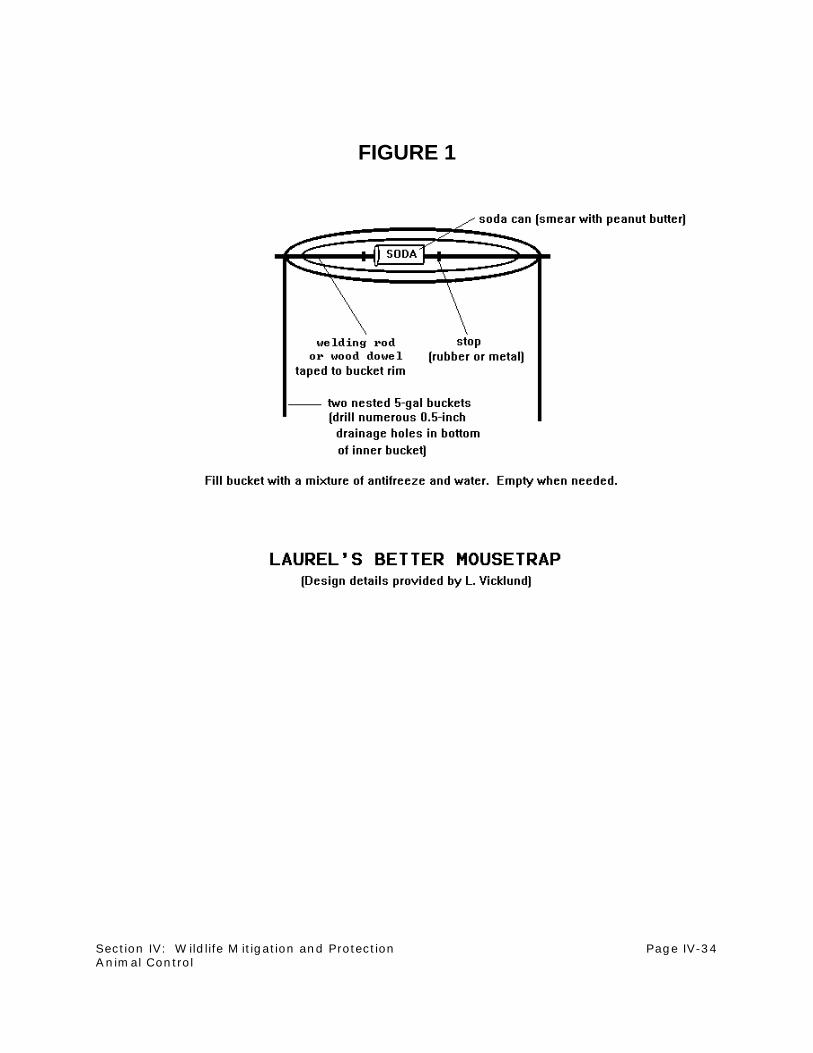
Section IV: Wildlife Mitigation and Protection Page IV-34Animal Control
FIGURE 1

Section IV: Wildlife Mitigation and Protection Page IV-35Animal Control
e. Raptor Nesting Control
Raptors nesting on highwalls or other operations areas can limit or stop mining activities.
Raptors, their nests, eggs, and young, are protected by Federal law. A conflict situation
may cause a delay of weeks or months, while operations are altered or suspended until the
young fledge from the nest.
To avoid potential raptor nesting/mining conflicts, it is extremely important that thorough
raptor surveys be conducted early each breeding season; especially in and near mining
areas where nesting cannot be tolerated. State and Federal agencies are more likely to
issue permits for raptor manipulation if a company has demonstrated willingness to
document potential conflict situations as early as possible each year.
Deterrence and relocation are methods used to control raptors nesting in unsuitable areas.
Deterrence is used to discourage nesting attempts early in the breeding season, prior to
egg-laying. Deterrence can be accomplished through barriers, removal of the nesting
substrate, audio scare devices, or other disturbing activity. Relocation of raptor nests is
discussed elsewhere in this section.
NOTE: Federal and State permits are required for any disturbance or manipulation
activities involving nesting raptors. If raptors show an interest in a particular site
(frequent perching, roosting, carrying nesting material), consultation with Federal and State
agencies should be initiated immediately to determine which methods of deterrence should
be employed. Deterrence is not always successful; the birds may not move, or may move
to a site that is even less suitable (from a mining standpoint) than the original site.
(1) Barriers
Barriers such as a wire cage or a tarp can be used to cover a potential nest site on
a highwall.
(2) Removal of Nesting Substrate
Substrate removal involves making the nest site permanently incapable of
supporting a nest. Highwall faces can be scraped or blasted to remove ledges or
potholes. Trees, windmills, old buildings, and other structures adjacent to mining

Section IV: Wildlife Mitigation and Protection Page IV-36Animal Control
activity can be removed. This strategy can be employed as a preventative measure,
even when no raptors have shown interest in a site.
(3) Audio Scare Devices
Audio scare devices, such as propane cannons and pistol-launched noisemakers,
can discourage raptors from using a potential nest area. These methods can be
quite labor-intensive. Cannons need to be repositioned frequently (every other day)
to maintain effectiveness, and field personnel must visit the site daily to employ
pistol rockets.
(4) Human Disturbance
Other disturbance can include flushing the birds from the site at every opportunity,
or simply increasing general mining activity in the area of nesting. Disturbance
should be used in conjunction with other methods, as raptors may simply tolerate
increased disturbance. Also, it may not be feasible to schedule work in an area for
a period of time long enough to discourage nesting activity.

Section IV: Wildlife Mitigation and Protection Page IV-37References
C. References
Wyoming Department of Environmental Quality, Land Quality Division (WDEQ-LQD). 1979.
WDEQ-LQD Guideline No. 10: Fencing. WDEQ-LQD, 122 W. 25th St., Cheyenne, WY
82002. 5 pp.
Bureau of Land Management. 1974. Proceedings: Regional Fencing Workshop. BLM, Washington,
D.C. 74 pp.
Olendorff, R.R., A.D. Miller, R.N. Lehman. 1981. Suggested Practices for Raptor Protection
on Power Lines -- State of the Art in 1981. Raptor Research Foundation, Carpenter St.
Croix Valley Nature Center, 12805 St. Croix Trail, Hastings, MN 55033. 111 pp.

Section IV: Wildlife Mitigation and Protection Page IV-38
NOTES
SECTION V
VEGETATION
Section Editor: Larry H. Kleinman
table of contents
Section V: Vegetation Page V-i
TABLE OF CONTENTS
SECTION V: VEGETATION
A. Introduction . . . . . . . . . . . . . . . . . . . . . . . . . . . . . . . . . . . . . . . . . . . . . . . . . . . . . . V-1
B. Establishing and Implementing a Revegetation Program . . . . . . . . . . . . . . . . . . . . V-3
1. Preparing a Revegetation Package . . . . . . . . . . . . . . . . . . . . . . . . . . . . . . . V-3
2. Cultivation Practices . . . . . . . . . . . . . . . . . . . . . . . . . . . . . . . . . . . . . . . . . . V-11
3. Drill Seeding Practices . . . . . . . . . . . . . . . . . . . . . . . . . . . . . . . . . . . . . . . . V-16
4. Hydroseeding Practices . . . . . . . . . . . . . . . . . . . . . . . . . . . . . . . . . . . . . . . V-22
5. Mulching Practices . . . . . . . . . . . . . . . . . . . . . . . . . . . . . . . . . . . . . . . . . . . V-26
6. Seed Handling . . . . . . . . . . . . . . . . . . . . . . . . . . . . . . . . . . . . . . . . . . . . . V-31
7. Planting Methods for Permanent Reclamation . . . . . . . . . . . . . . . . . . . . . . V-35
8. Broadcast Seeding . . . . . . . . . . . . . . . . . . . . . . . . . . . . . . . . . . . . . . . . . . . V-37
9. Transplanting Live Plants and Planting Plant Parts . . . . . . . . . . . . . . . . . . V-39
10. Reforestation . . . . . . . . . . . . . . . . . . . . . . . . . . . . . . . . . . . . . . . . . . . . . . . V-42
11. Seeding Shrub Seed . . . . . . . . . . . . . . . . . . . . . . . . . . . . . . . . . . . . . . . . . . V-46
C. Seed Ordering Methods . . . . . . . . . . . . . . . . . . . . . . . . . . . . . . . . . . . . . . . . . . . . V-52
1. Ordering Seed . . . . . . . . . . . . . . . . . . . . . . . . . . . . . . . . . . . . . . . . . . . . . . V-52
2. Preparing a Seed Purchase Request . . . . . . . . . . . . . . . . . . . . . . . . . . . . . V-54
3. Warm Season Grasses -- The Importance or Origin of
Named Varieties and Native Harvests . . . . . . . . . . . . . . . . . . . . . . . . . . . . V-58
4. Certified, Blue-tag Versus Non-certified (Common) Seed . . . . . . . . . . . . . V-62
5. Source-identified Yellow-tagged Seed . . . . . . . . . . . . . . . . . . . . . . . . . . . . V-64
6. Understanding Seed Tests . . . . . . . . . . . . . . . . . . . . . . . . . . . . . . . . . . . . . V-66
7. Determining Pure Live Seed . . . . . . . . . . . . . . . . . . . . . . . . . . . . . . . . . . . V-72
8. Selecting Good Shrub Seed . . . . . . . . . . . . . . . . . . . . . . . . . . . . . . . . . . . . V-74
D. Surface Stabilization . . . . . . . . . . . . . . . . . . . . . . . . . . . . . . . . . . . . . . . . . . . . . . V-80
1. Vegetative Surface Stabilization . . . . . . . . . . . . . . . . . . . . . . . . . . . . . . . . . V-80
2. Non-vegetative Surface Stabilization . . . . . . . . . . . . . . . . . . . . . . . . . . . . . . V-84
E. Husbandry . . . . . . . . . . . . . . . . . . . . . . . . . . . . . . . . . . . . . . . . . . . . . . . . . . . . . . V-86
1. Mowing for Weed Control . . . . . . . . . . . . . . . . . . . . . . . . . . . . . . . . . . . . . . V-86
2. Burning to Enhance Vegetation . . . . . . . . . . . . . . . . . . . . . . . . . . . . . . . . . V-88
3. Husbandry Grazing . . . . . . . . . . . . . . . . . . . . . . . . . . . . . . . . . . . . . . . . . . . V-90
F. Monitoring . . . . . . . . . . . . . . . . . . . . . . . . . . . . . . . . . . . . . . . . . . . . . . . . . . . . . . V-93
1. Vegetation Sampling . . . . . . . . . . . . . . . . . . . . . . . . . . . . . . . . . . . . . . . . . V-93
2. Recordkeeping Practices . . . . . . . . . . . . . . . . . . . . . . . . . . . . . . . . . . . . . V-103
3. Electronic Document Management in Mining . . . . . . . . . . . . . . . . . . . . . . V-109
G. References . . . . . . . . . . . . . . . . . . . . . . . . . . . . . . . . . . . . . . . . . . . . . . . . . . . . V-115

Section V: Vegetation Page V-ii
NOTES

Section V: Vegetation Page V-1Introduction
A. Introduction
Section editor: Larry H. Kleinman
~~~~~~~~~~~~~~~~~~~~~~~~~~~~~~~~~
Revegetation is the basis for most mined land reclamation programs. It is the final operation of the
mining process. The revegetated mined area must meet two basic objectives; forage and habitat
for livestock and wildlife suitable for the approved postmining land use must be provided, and
erosion from the mined lands must be controlled to the same extent that erosion is controlled on
undisturbed native lands. Vegetation grown on the mined area is the forage for animals, a basic
part of the habitat for animals, and the principal means of controlling erosion from mined lands.
There is not a single "best" method in all circumstances for any of the reclamation operations. The
procedures and techniques described in this section are some that have been proven successful
in at least one and possibly more situations.
The first subsections deal with establishing and implementing a revegetation program. The
objective of a revegetation program is to establish desirable vegetation. The procedures described
for establishing vegetation include topics such as seed-bed preparation, farming practices, seed
handling, planting, mulching, shrub establishment, and reforestation.
The second subsections deal with seed ordering. Seed quality is vitally important. The quality of
the seed many times determines the success or failure of a revegetation effort. Topics such as
seed ordering, preparing a seed purchase request, origins and quality of seed, seed tags (certified
and common seed), seed testing, and determining "Pure Live Seed" are discussed.
Surface stabilization is discussed in the third set of subsections. If the reclaimed land surface is
stable, then soil erosion from that land is controlled to the extent possible. Vegetative and non-
vegetative methods for stabilizing the land surface or controlling erosion are described.
After the vegetation is established, the husbandry (management) of the vegetation becomes critical
for its survival and longevity. The revegetation will degenerate to less than desirable cover and
production and to a less desired species composition without some type of management to sustain
it. Native plant species evolved under some type of foraging pressure. Non-use is not natural for
the species used in the revegetation programs. Therefore some type of management that at least
simulates "use" is vital for the maintenance of the revegetated stand. The husbandry practices
described in this fourth set of subsections include mowing for weed control, grazing, and burning.
Monitoring of the vegetation is the fifth set of subsections. It is important to know how the
vegetation is progressing toward the desired stage when the Final Reclamation Liability Bond can

Section V: Vegetation Page V-2Introduction
be released for the operator and the mined land can be put into production by the land owner. All
state regulatory agencies require that specific monitoring methods be approved and be a part of
the Mining Permit Application. Most states provide guidelines of methods of monitoring. Therefore,
the important non-regulated parts of this subsection include; vegetation sampling, recordkeeping
of the total operation, and Electronic Document Management in Mining.

Section V: Vegetation Page V-3Preparing a Revegetation Package
B. Establishing and Implementing a Revegetation Program
1. Preparing a Revegetation Package
Section editor: Larry H. Kleinman Subsection authors: D.G. Steward/Marlys M. Hansen
~~~~~~~~~~~~~~~~~~~~~~~~~~~~~~~~~
Situation:
Adequate preparation and planning are vital to the success of any revegetation program. A
revegetation package prepared for each planting season is a useful tool that will ensure sufficient
planning as well as provide clear, concise instructions to those performing the actual revegetation
work. It will also provide documentation for work accomplished, and serve as a record of
revegetation activities.
Special Considerations:
Inadequate preparation can lead to inefficient utilization of optimum weather conditions, as well as
improper fertilization, soil preparation, planting, or mulching methods. Proper planning by outlining
exact instructions or tolerances for each variable listed in the revegetation package ensures
suitable implementation of revegetation practices.
Requirements of seed per acre for each area in the revegetation package provides a base for
preparing a seed bid request. Husbandry practices, such as mowing, haying, interseeding, and
burning should also be included in the revegetation package.
Description of Technique:
a. Field Tour
The first step in the preparation of a revegetation package is to decide which areas (or
revegetation units) need work. A field tour is always necessary to ascertain the status of
these units. The field technicians who will be performing the planting can often be helpful
at this stage in providing input regarding possible methods.

Section V: Vegetation Page V-4Preparing a Revegetation Package
b. Decisions and Planning
First, decisions are made regarding which units will be included in the current revegetation
season. Then, each unit is categorized as permanent or temporary. Planning for permanent
units must be done with forethought about postmining land use requirements. Decisions
must be made regarding each of the variables that make up the revegetation package.
Table 1 provides an example of these variables, which are included in the revegetation
package.
c. Revegetation Package
Revegetation packages are composed of maps, revegetation unit requirements, and
information on seed mixes to be used.
(1) Maps
Each revegetation unit is drawn on a photo map of the mine area and given a
number (see "Unit Number" below). The map should then be drafted, and copies
included in the revegetation package. Each unit is digitized to determine it's
acreage.
(2) Revegetation Unit Requirements
Table 1 is an example page from a revegetation package with the information
required for the reclamation of each unit. A database is the best environment to use
in assembling this information. Units can then be sorted by category, seed mix, etc.
and requirements for mulch, fertilizer, and seed can be easily totalled. Additionally,
the package provides a base for recordkeeping and reporting of exact work
accomplished. The following variables may be included for each revegetation unit:
(a) Unit Number
One method of numbering is made up of year (96), Spring or Fall (S), and
number (01); 96S01. These numbers coincide with numbers placed on the
corresponding map.

Section V: Vegetation Page V-5Preparing a Revegetation Package
TABLE 1
1996 SPRING REVEGETATION PACKAGE
==========================================================
UNIT NUMBER: 96S01
---------------------------------------------------------------------------------------------------------------------------------------------------------------------------------------
GENERAL AREA: Jack's Flat
CATEGORY: Permanent Grazingland
ACRES: 91.1
DATE WORK MAY BEGIN: March 15, 1996
TASK SUGGESTED EQUIPMENT
---------------------------------------------------------------------------------------------------------------------------------------------------------------------------------------
Disc
Cultipack
Roll before Seeding
Seed
Hydroseed
Roll after Seeding
Mulch
Offset Disc, 6-inch
Cultipacker
48-inch Roller
Multi-box Drill w/Depth Bands
Hydroseeder
Tubgrinder
Crimper
---------------------------------------------------------------------------------------------------------------------------------------------------------------------------------------
SEED MIX: Permanent Grazingland
MULCH TYPE: Straw MULCH RATE: 1 ton/acre
NITROGEN: 10 PHOSPHORUS: 20 POTASSIUM: 10
REMARKS: Rockpick where needed
==========================================================

Section V: Vegetation Page V-6Preparing a Revegetation Package
(b) General Area
Each unit can be given a name or a description.
(c) Category
Permanent Grazingland, Topsoil Temporary, Long-term Temporary,
Husbandry, etc., are examples of categories that may be used.
(d) Acres
Acreages are determined by digitizing each unit on the map.
(e) Date work may begin
The earliest date work may commence for reclamation of that unit.
(f) Task
List in order exact reclamation practices to be used for each unit. Task and
equipment requirements are best listed in a multi-records table embedded
in the master table.
(g) Suggested Equipment
i) A dual-wheel tractor is needed for safe operation on slopes steeper
than 4:1.
ii) A hydroseeder may be required to ensure successful seeding of
small and trashy seed, and seed whose germination is enhanced by
light. It is also required on slopes too steep for drill seeding, and for
application of wood, paper, or synthetic fiber mulch.
iii) A multi-box drill may be required to ensure proper seeding and
coverage for a variety of seeds.
iv) A grain drill may be needed where grains are planted as a cover
crop.

Section V: Vegetation Page V-7Preparing a Revegetation Package
v) A 48-inch roller can be used to ensure a firm and evenly compacted
seed-bed, and optimum seed/soil contact. The roller can be used
before and after seeding. Rolling is particularly useful in dry
conditions where soil moisture is limited.
vi) A tubgrinder is used for the even application of grass and straw
mulch.
vii) A crimper is used for the adequate anchoring of grass and straw
mulch.
viii) A rotary mower may be required for certain husbandry practices.
ix) One or more of the following cultivation implements may be required
for seed-bed preparation. For more details on these implements,
please refer to the subsection "Cultivation Practices".
a) Plow
b) Chisel plow
c) Disk
d) Rotary hoe
e) Subsoiler
f) Harrow
g) Cultipacker
(h) Seed Mix
The named seed mix to be used for specific areas. Exact specifications for
each seed mix to be used are inserted separately in the package.
(i) Mulch Type
The type of mulch to be used on that unit.
(j) Mulch Rate
Tons per acre of mulch which is to be applied.
Section V: Vegetation Page V-8Preparing a Revegetation Package
(k) Nitrogen
Any requirements for fertilizer are determined from soil samples taken after
topsoil is laid.
(l) Phosphorus
Fertilizer requirement
(m) Potassium
Fertilizer requirement
(n) Remarks
Any specific requirements for the unit (may include safety specifications).
(3) Seed Mixes
Specific requirements for each seed mix to be used in reclamation are included in
each package. Table 2 shows an example page used in this portion of the package.
This spreadsheet shows pure live seed (PLS) per acre of each seed in the mix, lists
and totals acreages of the units requiring this seed mix, and multiplies the two to
show the total PLS required for each seed. This information is used in ordering the
seed required for revegetation during that season.

Section V: Vegetation Page V-9Preparing a Revegetation Package
TABLE 2
SEED MIX DESIGNATION: PERMANENT GRAZINGLAND
COMMON NAME SEEDER BOX* PLS RATE TOTAL PLS #
ALFALFA L 2 186.20
BIG SAGEBRUSH H 0.3 27.93
BLUE GRAMA L 2 186.20
BUFFALO GRASS M 2 186.20
FOUR WING SALTBUSH M 0.5 46.55
FRINGED SAGE L 0.5 46.55
GREEN NEEDLE B 4 372.40
PRAIRIE CONEFLOWER H .5 46.55
SLENDER WHEATGRASS B 2.5 232.75
SUNFLOWER L 0.5 46.55
THICKSPIKE WHEATGRASS B 3.5 325.85
WESTERN WHEATGRASS B 4 372.40
WINTERFAT M 1 93.10
YARROW L 0.5 46.55
UNIT ACRES
---------------------------------
96S01 91.1
96S02 2
TOTAL ACRES 93.1
=======================================*B - Back Box
L - Legume Box
M - Middle Box
H - Hydroseed

Section V: Vegetation Page V-10
NOTES

Section V: Vegetation Page V-11Cultivation Practices
2. Cultivation Practices
Section editor: Larry H. Kleinman Subsection authors: D.G. Steward/Marlys M. Hansen
~~~~~~~~~~~~~~~~~~~~~~~~~~~~~~~~~
Situation:
Cultivation practices break and loosen the soil surface to prepare a proper seed-bed. Cultivation
is necessary to provide a suitable environment for seed germination and root growth, as well as
for weed and moisture control.
Special Considerations:
Because initial surface conditions vary, as does the response of different seed species to soil
conditions, there are many methods of cultivation. The equipment used for cultivation will depend
on the method and magnitude of the cultivation practice.
Description of Technique:
a. Methods of Cultivation
All cultivation should be done parallel to the contour on slopes, and perpendicular to
prevailing winds on flat areas. This reduces the likelihood of erosion. The methods of
cultivation that may be used on the reclaimed surface include:
(1) Plowing
Plowing is used to initiate preparation of extremely hard or previously untilled
ground. The plow cuts, lifts, and turns ground, burying crop residue or vegetation,
and aerating the soil. Plowing can also be used to control weeds or incorporate
fertilizer.

Section V: Vegetation Page V-12Cultivation Practices
Variations in design of the plow bottom can allow for plowing in heavy clay or sticky
soil. Safety devices available include a safety trip release mechanism and a
hydraulic auto-reset, both of which prevent damage to the plow in rocky soils.
(2) Chisel Plowing
A chisel plow cuts through the soil without turning over the surface. This
encourages water infiltration and retention, and limits surface evaporation.
The chisel plow can be operated just deep enough to cut off weeds with a minimum
of surface disturbance. The cutting depth is dependent on soil conditions and
desired results. A wide variety of soil-engaging tools are available for varied depths
and tillage results.
(3) Disking
Disking cuts, lifts, and rolls the soil. Disking can be used for primary tillage of heavy
soils, for mulching crop residue, or to pulverize lumps and close air spaces after
plowing.
Disk scrapers can be added when necessary for use in sticky soil. Disking can also
be done in rocky soil, as disk blades will roll over obstructions. A tandem disk tills
the soil twice, leaving a more level surface. An offset disk moves soil in opposing
directions while also tilling the soil twice and leaving a level surface.
(4) Rotary Hoeing
A rotary hoe tills the surface of the ground with an implement that mimics the action
of a hoe. The resulting disturbance is only one to three inches in depth. Rotary
hoeing is good for shredding and mixing stubble, and for removing undesired
vegetation.
(5) Subsoiling
Subsoiling breaks up compacted soil layers beneath the surface without turning the
soil over. This improves water infiltration and drainage, and aerates subsoil layers
to encourage root penetration. Subsoiling can range in depth from 6 to 24 inches,

Section V: Vegetation Page V-13Cultivation Practices
and at shallow depths can be used to control undesirable vegetation. Subsoiling
works best in dry soil.
(6) Harrowing
A harrow scratches the surface of the ground to loosen a thin surface layer. Three
types are the spike-tooth, tine-tooth, and spring-tooth harrows. Harrows kill
undesirable vegetation by ripping out the plants roots. Harrowing also prepares the
surface of the soil for seeding by breaking up the top crust, shattering dirt clods, and
closing air pockets. Harrows prepare an excellent seed-bed for small seeds that
require fine, loose soil for good seed/soil contact and moisture absorption.
(7) Cultipacking
A cultipacker breaks clods and firms the soil surface better than most other
machines. It leaves a well pulverized, firmly packed soil for excellent seed/soil
contact.
The front rollers of a cultipacker crush clods and level the surface. Spring-teeth then
close air pockets and bring up buried clods for the rear roller to crush, leaving a
firm, level surface.
(8) Rolling
Rolling applies even pressure to a surface that has been previously cultivated. The
purpose of rolling is to create a firm planting bed for maximum seed/soil contact
without excessive compaction. Flexible frames will allow the roller to follow ground
contours for the best possible performance.
b. Husbandry
Seed-bed preparation often includes methods other than cultivation to prepare the surface
for planting. Rock removal, controlled burning, and biomass removal, such as is
accomplished by haying or combining, are seed-bed techniques that may be used on a
reclaimed surface. Other subsections within this section provide more information on
husbandry methods.
c. Safety

Section V: Vegetation Page V-14Cultivation Practices
Safety should always be a consideration in decisions of revegetation practices for a given
area. As a general rule, loose slopes steeper than 4:1, and firm slopes steeper than 3:1,
will require dual four wheel drive tractors for cultivation, drill seeding, and mulching. Loose
slopes steeper than 3:1, and firm slopes steeper than 2.5:1, will generally require
hydroseeding and hydromulching.
d. Tolerances
The primary purpose of the tolerance criteria is to provide an objective means of dispute
resolution, should such resolution become necessary between the mine supervisor and a
revegetation contractor. In addition, the tolerance criteria provide a means for the mine
supervisor to set a quantifiable standard for work performance. The application of tolerance
criteria is expected to be the exception rather than the rule.
(1) Disking
(a) Ridges and Valleys
Based on the average of one sample per acre per unit (minimum two
samples per unit, maximum ten), the height of ridges and depth of valleys
left as a result of disking shall not exceed two inches, for a maximum total
difference from top to bottom of four inches. Measurement is made by both
the contractor and the mine supervisor in randomly selected locations. If the
contractor and the mine supervisor cannot agree on sample locations and
measurements, independent measurement by the same means may be
made by a soil scientist or agricultural engineer.
(b) Depth of Cultivation
Based on the average of one sample per acre per unit (minimum two
samples per unit, maximum ten), the depth of disk harrowing shall be six
inches plus or minus two inches. Depth will be assessed by excavation of
a test hole and subsequent measuring. Measurement shall be made by both
the contractor and the mine supervisor in randomly selected locations. If
contractor and the mine supervisor cannot agree on sample locations and
measurements, independent measurement by the same means may be
made by a soils scientist or agricultural engineer.

Section V: Vegetation Page V-15Cultivation Practices
(2) Cultipacking
(a) Ridges and Valleys
Based on the average of one sample per acre per unit (minimum two
samples per unit), the height of ridges and depth of valleys left as a result
of cultipacking shall not exceed one inch, for a maximum total difference
from top to bottom of two inches. Measurement shall be made by both the
contractor and the mine supervisor in randomly selected locations. If the
contractor and the mine supervisor cannot agree on sample locations and
measurements, independent measurement by the same means may be
made by a soil scientist or agricultural engineer.
(b) Size of Clods
Based on the average of one sample per acre per unit (minimum two
samples per unit), the size of clods that remain after harrowing shall not
exceed three inches in the greatest dimension. Clod size will be assessed
by measurement of the largest clod within three feet of randomly located
points within the unit. Measurement shall be made by both the contractor
and the mine supervisor in randomly selected locations. If the contractor and
the mine supervisor cannot agree on sample locations and measurements,
independent measurement by the same means may be made by a soils
scientist or agricultural engineer.
(3) Rolling
Based on the average of one sample per acre per unit (minimum two samples per
unit, maximum ten), the average depth of three footsteps (made by an
approximately 170 pound person) closest to randomly located points in the unit may
not exceed 3/4 inch. Measurement shall be made by both the contractor and the
mine supervisor. If the contractor and the mine supervisor cannot agree on sample
locations and measurements, independent measurement by the same means may
be made by a soils scientist or agricultural engineer.
Section V: Vegetation Page V-16Drill Seeding Practices
3. Drill Seeding Practices
Section editor: Larry H. Kleinman Subsection authors: D.G. Steward/Marlys M. Hansen
~~~~~~~~~~~~~~~~~~~~~~~~~~~~~~~~~
Situation:
Drill seeding is generally the most effective method of planting most seed types for both permanent
and temporary reclamation. However, a combination of drill seeding and hydroseeding is one
preferred method of seeding permanent reclamation. While most seed is best drill seeded,
hydroseeding may be preferred for certain species such as shrub seed, which, because of low
purity and germination, must be seeded in large amounts. For safety purposes, most slopes
steeper than 2.5:1 will require hydroseeding rather than drill seeding.
Weather and soil conditions permitting, permanent seeding should be done as soon as practicable
after topsoil is laid on reclaimed ground. A season or more of annual grains cropping may enhance
seeding success by improving soil tilth and soil moisture. Temporary seeding, which should not be
performed when the probability of adequate moisture for seedling establishment is low, is
necessary for erosion control on areas such as topsoil stockpiles. All revegetation must be done
in the manner most efficient for moisture retention and erosion control.
Special Considerations:
Antecedent soil moisture has a large impact on seeding success. It is undesirable to seed into
powder-dry earth, unless there is a high probability of a significant period of postseeding
precipitation. Soil with moisture as close as possible to field capacity, but which can also be seeded
without undue compaction, is most likely to support successful germination.
In Wyoming, seeding early in the spring, even in January or February, has consistently resulted in
successful establishment, particularly of cool season grasses and shrubs.

Section V: Vegetation Page V-17Drill Seeding Practices
Description of Technique:
a. Three common types of drill seeders are:
(1) Grain Drill
The grain drill is for flowable seeds such as oats and wheat. It should have a
legume box and a drill range that adjusts from six to fifty pounds per acre.
(2) Grass Drill
The grass drill will efficiently seed the majority of seed varieties. This drill should
have: chain drags, press wheels, one-half to one inch depth bands, and a drill
range that adjust from six to sixty pounds per acre. This will ensure even seeding
and proper depth and coverage of seeds. It should also have three seed boxes with
agitators to keep seed mixed:
(a) A legume box for small seed
(b) A box with picker wheels for trashy seed
(c) A standard box for flowable seeds such as grains
(3) No-till Drill
The no-till drill has characteristics similar to the grass drill. In addition, it has coulter
wheels to cut through surface vegetation and open a narrow path for seeding. The
no-till drill may be used where it is desired to minimize surface disturbance.
b. Method
All drill seeding should be done parallel to the contour on slopes, or perpendicular to the
prevailing wind on flat areas. Calibration of the drill must be accurate to ensure the correct
PLS of each seed is planted. Table 1 gives step-by-step instructions for drill calibration.

Section V: Vegetation Page V-18Drill Seeding Practices
TABLE 1SAMPLE DRILL CALIBRATION
1 revolution of the drive tire is 7.667 feet. (This depends on tire size.)The drill seeds 10 feet wide. (This depends on the drill.)There are 43,560 square feet per acre.
568.15 revolution would equal 1 acre covered:
43,560 sq.ft./acre = 568.157.667 ft/rev X 10 ft wide rev/acre
There are 16 furrow openers. (This depends on the drill.)2.2 pounds equals 1 kilogram.1 kilogram = 1,000 grams
BOX BULK LBS. PLS LBS. SPECIES
Middle 1.34 1.0 Little bluestemMiddle 3.78 2.0 Fourwing saltbushLegume 5.10 2.0 Blue gramaBack 3.36 3.0 Green needleMiddle 1.18 1.0 Side oats gramaLegume 1.05 1.0 AlfalfaMiddle 2.24 2.0 Buffalo grassBack 3.83 3.0 Slender wheatgrassBack 2.22 2.0 Thickspike wheatgrassBack 3.44 3.0 Western wheatgrassMiddle 0.55 0.5 Sanfoin
Note: Bulk needed for the required PLS will change slightly when using different lots, vendors, etc.
MIDDLE LEGUME BACK
Little bluestem 1.34 Blue grama 5.10 Western 3.44Fourwing 3.78 Alfalfa 1.05 Thickspike 2.22Side oats 1.18 6.15 lbs. Slender 3.83Buffalo grass 2.24 bulk Green needle 3.36Sanfoin 0.55 12.85 lbs.
9.09 lbs. bulk bulk
9.09 lbs. = 4.132 KG 6.15 lbs. = 2.795 KG 12.85 lbs. = 5.841 KG2.2 KG/lb. 2.2 KG/lb. 2.2 KG/lb.
To change kilograms to grams multiply by 1,000.
4,132 grams of bulk needed for the middle box per acre.2,795 grams of bulk needed for the legume box per acre.5,841 grams of bulk needed for the back box per acre.

Section V: Vegetation Page V-19Drill Seeding Practices
TABLE 1 (continued)
Now we want to find out how many grams we need for 1 revolution for 1 seed cup (opener):
4.132 grams/acre = 0.4545 grams/revolution16 openers X 568.15 revolution/acre for 1 opener
OR
4.132 grams = 0.4545 grams9090.4
0.4545 grams is too small to weigh on most scales accurately. So we spin the drive tire 10 times whentesting which is more accurate.
4.545 grams is what the middle box seed should weigh for 10 revolutions.
The back box bulk grams required (cutting out the extra numbers) would be:
5,841 grams X 10 revolutions = 6.425 grams9090.4
2.795 grams X 10 revolutions = 3.075 grams9090.4
The bulk pounds needed must be calculated by the seed tags.* Add the bulk pounds up for each box,convert to kilograms, then to grams.
bulk grams X 10 revolutions = grams9090.4
*In order to figure PLS you will need to MULTIPLY:
Purity from the seed tag X Germination from the seed tag = PLS

Section V: Vegetation Page V-20Drill Seeding Practices
c. Tolerances
The primary purpose of the tolerance criteria is to provide an objective means of dispute
resolution, should such resolution become necessary between the mine supervisor and a
revegetation contractor. In addition, the tolerance criteria provide a means for the mine
supervisor to set a quantifiable standard for work performance.
(1) Seed Mixing
(a) Computation Tolerance
Acceptable tolerances for mixing seed to be used in drill seeding will be
based on the proper computation of bulk pounds of the mix for each box.
The record of seed mixing for any individual revegetation unit, including the
computation of the proper bulk mix, should indicate a deviation of not
greater than ten percent from the properly calculated bulk mix. This
tolerance criterion applies to each species seeded by the box being
evaluated.
For example, if the proper computation of bulk pounds requires ten bulk
pounds of species A in the back box of a three-box drill for each acre
seeded, and the computation made by the contractor shows eight pounds,
the deviation from the tolerance is greater than ten percent.
(b) Application Tolerance
The tolerance is based on the average of three samples per box per unit,
taken before the drill is loaded. The proportion of bulk pounds for each
species for the box, compared to total bulk pounds for the box, will be within
50 percent (as estimated visually) of the properly computed ratio described
above.
For example, if the bulk pounds of species A is two pounds per acre for the
back box of a three-box drill, and the total bulk pounds of the mixed seed for
the back box is twenty pounds per acre, the proportion of species A must be
between 1/20 (five percent) and 3/20 (fifteen percent), as estimated visually.
Species comprising less than five percent of the bulk mix by computation
need only be visually present to meet the seed mixing tolerance.

Section V: Vegetation Page V-21Drill Seeding Practices
Assessment of seed mixing is made prior to hydroseeding. If the contractor
and the mine supervisor cannot agree on the average visual estimate of
mixing, independent measurement by the same means may be made by a
vegetation scientist or agricultural engineer.
(c) Seed Density
Based on the average of one sample per acre per unit (minimum two
samples per unit, maximum ten), the average unit density of seeds in a 12
inch wide by 24 inch long block shall be equivalent to plus or minus 30
percent of the pounds of PLS per acre required by the seed mix being
applied. The location of the sample squares should be made by the mine
supervisor. Computation of pounds of PLS per acre is made for each mix
prior to drill seeding.
Seed count can be made by the mine supervisor and confirmed by the
contractor. If the contractor and the mine supervisor cannot agree on
sample locations and measurements, independent measurement by the
same means may be made by a vegetation scientist or agricultural engineer.
(2) Seed Depth
Based on the average of one sample per acre per unit (minimum two samples per
unit, maximum ten), the average depth of seeds in a 12 inch wide by 24 inch long
block shall be between 1/4 and 1 inch. The sample squares will be randomly
located. Seed depth can be measured by the mine supervisor and the contractor.
If the contractor and the mine supervisor cannot agree on sample locations and
measurements, independent measurement by the same means may be made by
a vegetation scientist or agricultural engineer.
Section V: Vegetation Page V-22Hydroseeding Practices
4. Hydroseeding Practices
Section editor: Larry H. Kleinman Subsection authors: D.G. Steward/Marlys M. Hansen
~~~~~~~~~~~~~~~~~~~~~~~~~~~~~~~~~
Situation:
A combination of drill seeding and hydroseeding is preferred for seeding permanent reclamation.
A hydroseeder is also required on slopes too steep for drill seeding, and for application of mulch.
It may also be used to ensure successful seeding of small seed, trashy seed, and seed whose
germination is enhanced by light.
Special Considerations:
A successful seeding program includes both drill seeding and hydroseeding. Several factors must
be considered in deciding which method will be most efficient and successful. When hydroseeding
is the best choice, it must be done properly to avoid damaging seed.
Description of Technique:
a. When to Hydroseed
(1) Trashy Seed
Hydroseeding is an option for trashy seed, such as little bluestem, blue grama, and
prairie sandreed. It is often preferred, however, that seed be cleaned and drill
seeded when possible.
(2) Seed Enhanced by Light
Hydroseeding may be the best choice for seed such as sand dropseed and
sagebrush, which grow best near the surface where light enhances germination.

Section V: Vegetation Page V-23Hydroseeding Practices
(3) Seed with Low PLS
Shrub seed, such as sagebrush, rubber rabbitbrush, and winterfat, often has a very
low PLS, and must be applied in large quantities. Hydroseeding is the most efficient
choice, as one pass with a hydroseeder will seed the required amount, which may
take two or more passes with a seed drill.
(4) Mulch Application
Mulch should be applied in a separate step, after hydroseeding. This enhances the
seed/soil contact and optimizes seed protection. Wood, paper, and synthetic fiber
mulch are applied in a water slurry at recommended rates. Synthetic fiber may also
require a hydroseeder, and should be applied according to the manufacturer's
instructions.
(5) Safety
On steep slopes, safety considerations make it necessary to apply all seed and
mulch with a hydroseeder. Generally, loose slopes steeper than 3H:1V, and firm
slopes steeper than 2.5H:1V will require a hydroseeder.
b. Methods
(1) Avoid Seed Damage
Agitation of seed and water in the hydroseeder should be at the lowest possible
rate, in order to avoid damage to the seed. Using very high water pressure may also
cause seed damage.
(2) Attain Complete Seed Coverage
Hydroseeding on slopes should be done from both the bottom and top of the hill to
ensure complete coverage.
(3) Mulch
Applying the average requirements for mulch with the seed can hinder seed/soil
contact. The bulk of the mulch should be applied after all seeding is complete. A

Section V: Vegetation Page V-24Hydroseeding Practices
small amount of wood or paper mulch, however, works as a good defoaming agent,
especially with shrub seed. An organic hydrocolloid tackifier and dye can be used
with paper and wood fiber mulch. Tackifier should not be used with seed, however,
as damage may result.
c. Tolerances
The primary purpose of tolerance criteria is to provide an objective means of dispute
resolution, should such resolution become necessary between the mine supervisor and a
revegetation contractor. In addition, the tolerance criteria provide a means for the mine
supervisor to set a quantifiable standard for the work performance of the contractor. The
application of tolerance criteria is expected to be the exception rather than the rule.
(1) Seed Mixing
Acceptable tolerance for mixing seed to be used for hydroseeding is based on the
proper computation of bulk pounds for the hydroseed mix and the record of pounds
of seed placed in each hydroseeder load. The record of hydroseeding for any
individual unit, including the computation of the proper bulk mix, should not deviate
more than ten percent from the properly calculated bulk mix. This criterion applies
to each species seeded by the hydroseeder.
For example, if the proper computation of bulk pounds requires ten bulk pounds of
species A in the hydroseeder for each acre seeded, and the computation made by
the contractor shows eight pounds, the deviation from the tolerance is greater than
ten percent.
(2) Seed Density
Based on the average of one sample per acre per unit (minimum two samples per
unit, maximum ten), the average unit density of seeds on a cardboard square 12
inches by 12 inches shall be equivalent to plus or minus 30 percent of the number
of bulk seed per acre required by the seed mix being applied. For example, if proper
computation of the bulk mix calls for 4,356,000 seeds per acre to be applied, the
square should contain between 70 and 130 seeds. The placement of the cardboard
square will be made by the contractor or employee in the field as approved by the
contractor or the mine supervisor. Computation of pounds of bulk seed per acre will
be made for each mix prior to hydroseeding.

Section V: Vegetation Page V-25Hydroseeding Practices
Seed count of the cardboard square can be made by the contractor and confirmed
by the mine supervisor. If the contractor and the mine supervisor cannot agree on
sample locations and measurements, independent measurement by the same
means may be made by a vegetation scientist or agricultural engineer.

Section V: Vegetation Page V-26Mulching Practices
5. Mulching Practices
Section editor: Larry H. Kleinman Subsection authors: D.G. Steward/Marlys M. Hansen
~~~~~~~~~~~~~~~~~~~~~~~~~~~~~~~~~
Situation:
Mulch, made of plant residue or other suitable materials, is placed upon a recently seeded soil
surface to aid in soil stabilization and soil moisture conservation.
Special Considerations:
Mulch should be applied immediately after seeding, and never with seed; this maximizes contact
of soil and seed. Mulch need not be used if seed has been planted into a cover crop or standing
stubble.
Description of Technique:
a. Application Rates and Methods
Recommended application rates proposed for various conditions of slope and soil are
presented in Table 1 (tables are at end of text). One or more of the methods specified for
each of the conditions shown in the table should be applied to a seeded surface. Mulch
rates will vary, dependent upon the type of mulch used and manufacturer's
recommendations. Where mulch is used to control erosion, the amount used will depend
upon steepness of the slope. The types of mulch that may be used include:
(1) Nurse Crop
Oats, at no less than six pounds and no more than fifteen pounds per acre, are
included in the approved perennial seed mix at the time of planting.

Section V: Vegetation Page V-27Mulching Practices
(2) Cover Crop
Oats, at no less than fifteen pounds and no more than sixty pounds per acre, are
planted the season prior to the approved perennial mix. The cover crop may be
hayed or combined, and the perennial is then planted into the standing stubble.
(3) Native Hay
Hay is applied with a tub grinder or similar blower, at a rate of between 1/2 and two
tons per acre, and then crimped into the ground with a flat blade disc crimper.
Crimping should be done 1/2 to 2 inches deep, on eight to twelve inch centers.
(4) Straw
Certified weed-free straw is applied and crimped in a fashion similar to native hay
mulch.
(5) Wood Fiber
Wood fiber is applied as a hydromulch at a rate of between 1/2 and 1 ton per acre.
An organic hydrocolloid tackifier and dye should be used with wood fiber.
(6) Paper Fiber
Paper fiber is applied similar to wood fiber, with tackifier and dye.
(7) Wood/Paper Fiber
A mixture of fiber is applied similar to wood fiber, with tackifier and dye.
(8) Synthetic Fiber
Synthetic mulch is applied in accordance with manufacturers instructions.
b. Equipment
(1) A hydroseeder is used for application of wood, paper, or synthetic fiber mulch.

Section V: Vegetation Page V-28Mulching Practices
(2) A tubgrinder is required for even application of grass and straw mulch.
(3) A crimper is needed for the adequate anchoring of grass and straw mulch.
(4) A smooth-fronted roller is used in place of, or in conjunction with, other methods of
mulching to meet desired performance standards.
c. Tolerances
The primary purpose of the tolerance criteria is to provide an objective means of dispute
resolution, should such resolution become necessary between the mine supervisor and a
revegetation contractor. In addition, the tolerance criteria provide a means for the mine
supervisor to set a quantifiable standard for work performance. The application of tolerance
criteria is normally the exception rather than the rule.
Evaluation of mulching is made from the records of the contractor, who must report the
bags or tons of mulch applied per unit. The amount of mulch applied must be within plus
or minus 20 percent of the prescribed amount for the unit. For example, if hydromulching
of the unit calls for the application of 0.5 ton of mulch per acre and the records show less
than 0.4 or more than 0.6 ton per acre was applied, the contractor will have failed to meet
the tolerance for that unit.
In the case of insufficient mulch, additional mulch should be applied at the discretion of the
supervisor. If too much mulch has been applied, the area may require re-seeding,
depending on seeding success. In no case should payment be made for more than the
specified amount of mulch.

Section V: Vegetation Page V-29Mulching Practices
TABLE 1
MULCHSOIL TYPE
Primarily Sandy -"Light"
Primarily Silty or"Medium"
Primarily Clayey or"Heavy"
Methods of Mulch ApplicationSlope less than 2.5H:1V
nurse crop rate
cover crop rate
native hay rate
straw rate
fiber rate
synthetic rate
12 lbs
40 lbs
1 ton
1 ton
2 tons
manufacturersspecifications
12 lbs
40 lbs
1 ton
1 ton
2 tons
manufacturersspecifications
12 lbs
40 lbs
1 ton
1 ton
2 tons
manufacturersspecifications
Methods of Mulch ApplicationSlope 2.5H:1V to 5H:1V
nurse crop rate
cover crop rate
native hay rate
straw rate
fiber rate
synthetic rate
12 lbs
30 lbs
1 ton
1 ton
2 tons
manufacturersspecifications
12 lbs
40 lbs
1 ton
1 ton
2 tons
manufacturersspecifications
12 lbs
40 lbs
1 ton
1 ton
2 tons
manufacturersspecifications
Methods of Mulch ApplicationSlope greater than 5H:1V
nurse crop rate
cover crop rate
native hay rate
straw rate
fiber rate
synthetic rate
12 lbs
40 lbs
1 ton
1 ton
2 tons
manufacturersspecifications
12 lbs
40 lbs
1 ton
1 ton
2 tons
manufacturersspecifications
12 lbs
40 lbs
1 ton
1 ton
2 tons
manufacturersspecifications

Section V: Vegetation Page V-30
NOTES

Section V: Vegetation Page V-31Seed Handling
6. Seed Handling
Section editor: Larry H. Kleinman Subsection authors: D.G. Steward/Marlys M. Hansen
~~~~~~~~~~~~~~~~~~~~~~~~~~~~~~~~~
Situation:
Before seed is received by reclamation personnel, careful handling, ordering, and testing ensures
the best possible quality. Proper care must continue after seed is received to maintain this high
quality.
Special Considerations:
Seed storage facilities must be adequate to maintain seed quality. Expertise is necessary in the
preparation of seed mixes to ensure the proper PLS of each seed is included in the mix, and to
prevent damage to seed.
Description of Technique:
Seed must be stored in a facility that will ensure a temperature controlled, moisture-free
environment. This will prevent mold, heat damage, or premature germination of seed. The use of
a rat poison is usually necessary to control vermin.
Once seed has been delivered to the storage area, additional testing may be required for
verification of purity, germination, and weed content. Employing a state seed inspector for obtaining
samples will assure both the vendor and the buyer that this is done properly. Samples should be
sent to a certified seed laboratory for testing. For more details on seed testing, refer to the
subsection entitled "Understanding Seed Tests".
Familiarity with the physical characteristics of different species is necessary in determining the best
method of seeding. Visual assessment is possible with the use of a seed library. To make a seed
library, fill small, clear bottles (like spice jars) with seed samples. Label each with seed name,
number of seeds per bulk pound, or other data desired. The seed library can be very helpful in
seed mixing and drill calibration.

Section V: Vegetation Page V-32Seed Handling
Table 1 lists some common species used in reclamation, with the drill box or method preferred for
best results in planting. Species to be used in each seed box must be mixed according to PLS
requirements per acre and total acreage to be seeded. Seed to be mixed in the hydroseeder should
be agitated gently to avoid damage. Care must also be exercised when using a hopper wagon for
mixing seed, as mixing too long and hard can easily cause damage to seed. With extremely dusty
seed, such as saltbush, it may be preferred to mix by hand in the seed box.

Section V: Vegetation Page V-33Seed Handling
TABLE 1
SEED PLANTING METHODS
SCIENTIFIC NAME COMMON NAME
DRILL BOXor
METHOD*
Achillea lanulosaAgropyron dasystachyumAgropyron elongatumAgropyron intermediumAgropyron ripariumAgropyron smithiiAgropyron trachycaulumAgropyron trichophorumArtemisia canaArtemisia frigidaArtemisia tridentataAstragalus cicerAtriplex canescensAtriplex gardneriAvena fatuaBouteloua curtipendulaBouteloua gracilisBromus enermisBuchloe dactyloidesCalamovilfa longifoliaCeratoides lanataChrysothamnus nauseosusDistichlis strictaHelianthus annuusLupinus caudatusMedicago sativaMelilotus officinaleOnobrychis viciaefoliaOryzopsis hymenoidesPetalostemum purpureumPhalaris arundinaceaPoa canbyiPoa pratensisRatibida columnifera (columnaris)Schizachyrium scopariumSecale cerealeSpartina pectinataSporobolus airoidesStipa viridulaTriticum aestivum - SpringTriticum aestivum - Winter
WESTERN YARROWTHICKSPIKE WHEATGRASSTALL WHEATGRASSINTERMEDIATE WHEATGRASSSTREAMBANK WHEATGRASSWESTERN WHEATGRASSSLENDER WHEATGRASSPUBESCENT WHEATGRASSSILVER SAGEBRUSHFRINGED SAGEWORTBIG SAGEBRUSHCICER MILKVETCHFOUR WING SALTBUSHGARDNER'S SALTBUSHOATSSIDE OATS GRAMABLUE GRAMASMOOTH BROMEBUFFALO GRASSPRAIRIE SANDREEDWINTERFATRUBBER RABBITBRUSHINLAND SALTGRASSSUNFLOWERLUPINEALFALFAYELLOW SWEET CLOVERSAINFOININDIAN RICEGRASSPURPLE PRAIRIE CLOVERREED CANARYGRASSCANBY BLUEGRASSBLUEGRASSPRAIRIE CONEFLOWERLITTLE BLUESTEMRYEPRAIRIE CORDGRASSALKALI SACATONGREEN NEEDLESPRING WHEATWINTER WHEAT
LRRRRRRR
H/PL
H/PRPPGPLRPR
H/PH/PRPPLLPRLRRLLPGRLRGG
* G - Grain drill H - Hydroseeder L - Legume box - grass drill P - Seed box with picker wheels - grass drill R - Regular box

Section V: Vegetation Page V-34
NOTES

Section V: Vegetation Page V-35Planting Methods for Permanent Reclamation
7. Planting Methods for Permanent Reclamation
Section editor: Larry H. Kleinman Subsection authors: D.G. Steward/Marlys M. Hansen
~~~~~~~~~~~~~~~~~~~~~~~~~~~~~~~~~
Situation:
Choosing the proper methods for cultivation and planting of reclaimed ground is vital to
revegetation success. The order of these methods is also important in producing a properly
prepared seed-bed for the best possible germination of seed.
Special Considerations:
Reclaimed ground must receive adequate tillage, but excess tillage should be avoided. The final
seed-bed should be finely pulverized, but firmly packed. The different seeds should be planted at
depths appropriate to the seed type, with the best possible contact between seed and soil.
Description of Technique:
a. The following steps have proven successful in permanent revegetation in the Powder River
Basin, and should be completed in the order given. For detail on methods, refer to the
individual subsections that cover each of these steps.
(1) Disk
Plowing freshly laid topsoil is usually unnecessary. Disking is typically the best initial
measure for soil preparation.
(2) Cultipack
Using a cultipacker is the next step in seed-bed preparation. Cultipacking will
ensure that the soil is finely pulverized, firmly packed, and ready to receive seed.

Section V: Vegetation Page V-36Planting Methods for Permanent Reclamation
(3) Hydroseed
Hydroseeding (without mulch!) is the most efficient choice for shrub seed, which,
because of low PLS, must be applied in large quantities. Hydroseeding is also
efficient for fluffy or trashy seeds. Hydroseeding is especially good for seeds such
as sagebrush, whose germination is enhanced by light. Hydroseeding should follow
cultipacking.
(4) Roll
Rolling is done after hydroseeding to firm the soil and ensure maximum seed/soil
contact. This is an essential practice. A typical smooth front roller is three feet in
diameter and can be filled with water for weight.
(5) Drill
A multi-box grass drill is required for seeding the species not seeded with the
hydroseeder. For details on determining the best seed box to use for each species,
refer to the subsection entitled "Seed Handling". The drill should have a chain-drag
attached to ensure even coverage of seed.
(6) Roll
Rolling should be done once again after all seed has been planted. This will firm the
soil adequately and ensure the best possible seed/soil contact.
(7) Mulch
Mulching, where necessary, should be done after all seed is in the ground. It is
desirable to avoid the use of mulch over species that require light to germinate,
such as shrub seed, and species that have a shallow planting depth, as mulching
may destroy seed/soil contact and/or increase surface drying.

Section V: Vegetation Page V-37Broadcast Seeding
8. Broadcast Seeding
Section editor: Larry H. Kleinman Subsection author: Laurel E. Vicklund
~~~~~~~~~~~~~~~~~~~~~~~~~~~~~~~~~
Situation:
There are occasionally areas requiring seeding that are not accessible with a pull-type seed drill.
Not all of the areas that require seeding will be final reclamation; special-use areas may be small,
rocky, have a steep slope, have peculiar seeding requirements, or be inaccessible to a tractor and
drill. Using various methods to broadcast the seed ensures that the area is planted to stabilize the
surface.
Special Considerations:
Areas with excessive slopes should be evaluated for safe access before using tractors and other
equipment. Establishment of vegetative cover in "fringe" areas reduces erosion, sediment runoff,
and the potential for noxious weed invasion as well as improving air quality by reducing wind
erosion. When hydroseeding is not essential, broadcast seeding is more economical.
Description of Technique:
a. Mechanical Broadcast Seeding
A seed broadcaster that fits on a three-point tractor hitch and runs off the power-take-off
is very convenient for seeding small areas. Vegetation establishment may be required on
areas not scheduled for final reclamation, such as overburden areas, sediment ditches or
ponds, around rockpiles, or other open areas of disturbance.
Some areas may be too rough to pull an expensive seed drill over. This may be especially
true of backfill requiring interim stabilization, which is often too rocky. Using a broadcaster
to seed these areas reduces excessive wear on a pull-type drill. Other areas may be
inaccessible to a pull-type drill, such as scraper-built sediment control ditches or other small
"fringe" areas around the pit.

Section V: Vegetation Page V-38Broadcast Seeding
(1) Seeding Rate
Generally, regular reclamation seed mixtures can be used for broadcast seeding by
doubling the rate. The rate is increased to compensate for seed not placed at the
proper depth, that may be washed away, or that will not germinate.
A harrow or a chain drag is pulled behind the seed broadcaster to aid in covering
seed. Calibration varies with the brand of seed broadcaster, and the type of seed
used. Follow the instructions for calibration that comes with the seed broadcaster.
(2) Shrub Seeding
A seed broadcaster can be used in conjunction with a pull-type seed drill. This
procedure has been used when the seeding rate of a shrub species could not be
applied through a conventional drill. The grass component of the seed mixture is
drilled into a standing stubble mulch. The shrub portion of the mixture is then
broadcast into the same area, however a harrow or chain drag is not used behind
the broadcaster in this instance.
b. Hand Broadcasting
Hand broadcasting is useful in small areas where access is limited, or in areas where a
small amount of a specific seed is to be planted. A hand type seed broadcaster may be
used, or seed may simply be scattered by hand. Hand seeding works well around rockpiles,
wetland areas, and other small areas inaccessible to pull-type drills or mechanical seed
broadcasters.
Calibration is less accurate with these methods of seeding. Calculate the acreage of the
area to be seeded and the volume of seed required for the area, and distribute the seed as
evenly as possible. As with the mechanical broadcaster, the amount of seed applied should
be doubled.

Section V: Vegetation Page V-39Transplanting Live Plants and Planting Plant Parts
9. Transplanting Live Plants and Planting Plant Parts
Section editor: Larry H. Kleinman Subsection author: Larry H. Kleinman
~~~~~~~~~~~~~~~~~~~~~~~~~~~~~~~~~
Situation:
Planting and transplanting are sometimes necessary to establish a seed source of shrubs and trees
for further enrichment of a revegetated stand. Certain shrub and tree seeds germinate only
sporadically in the wild and those species should be included in the revegetation as transplants.
Special Considerations:
Planting and transplanting may take place prior to seeding of the normal seed mixtures, after
seeding, or even with no seeding whatsoever. Several of the methods described are labor
intensive, expensive, and may require specialized equipment; others are relatively inexpensive,
easily performed, and require no specialized equipment. The methods that are described in this
subsection are; containerized stock, bareroot stock, shrub/tree pads, and sprigs or cuttings.
Moisture competition by grasses and weedy plants may be the most probable cause of shrub and
tree transplant failure. When planting or transplanting into an already established stand or a newly
seeded area, the existing living plant material should be removed from the soil immediately around
the transplants. This can be done by scalping to just below bare ground or by herbicidal control.
Normal seed mixtures may be interseeded into the plantings; preferably after the new plants are
well established. Methods that can be utilized for the seeding include no-till drills, grass seeders
such as the "Brillion" (raise the roller packers so that they do not disturb the transplants),
hydroseeders, or broadcast seeders such as the "Cyclone" seeder. It is recommended to reduce
the normal interseeding mixture by as much as one-half to reduce competition. If directly placed
topsoil is used for the top dressing before transplanting, no additional seeding may be necessary.
Match the directly placed topsoils with the type of plantings. For example, chances of success
would be improved if ponderosa pine transplants were planted into directly placed pine soils.
The planting and transplanting of live plants may be undertaken in the spring or fall, provided
certain precautions are taken. The plants should be hardened (dormant), and there should be
adequate soil moisture, or at least the chance for adequate soil moisture.

Section V: Vegetation Page V-40Transplanting Live Plants and Planting Plant Parts
Description of Technique:
a. Containerized Stock
Containerized transplants of shrubs or trees may be obtained in almost any size desired,
from six cubic-inch cones to five gallon buckets. Many nurserymen and planters prefer a
ten cubic inch cone container, as they are easily handled and planted with small chance of
root disturbance. They produce vigorous and straight root growth. The above-ground
portion of the plant is vigorous, well formed, and generally one year old stock.
Containerized plants are quite expensive to get into the ground. Each individual plant may
cost up to approximately $2.00 per plant to buy and have planted by professional planters.
If mine laborers do the planting, the cost may be several times the $2.00 per individual
plant. Care must be taken to plant the transplant correctly without bending the roots, without
leaving too much airspace around the roots, and to put the plant in the most appropriate
niche.
There are mechanical rotary tree planters available that are pulled behind a tractor. These
reduce the final cost considerably if several thousand trees or shrubs are to be planted per
day. A professional planter is able to plant 400 to 600 trees per day in a precise location,
whereas a mechanical planter is able to plant up to 2,000 or more trees per day.
b. Bareroot Stock
The same considerations and techniques given for containerized plants are appropriate for
bareroot transplants. In general, bareroot stock is less expensive to buy but more care must
be taken to keep the roots from drying out before planting. There are fewer fine root hairs
to immediately begin growth than with containerized plants. Thus the plants must utilize
more stored carbohydrates to initiate growth of root hairs for water and nutrient uptake.
More care must be taken to keep from bending the roots than for containerized plants, and
in some cases the roots and the crown should be pruned before planting.
c. Shrub/Tree Pads - Front-End Loader Bucket
This technique is a simple, inexpensive, and rapid method of transplanting a whole pad or
clone of certain trees and shrubs. Plant species that spread by rhizomes, adventitious
stems, or root sprouting are the most successful in establishing by this technique. Species
Section V: Vegetation Page V-41Transplanting Live Plants and Planting Plant Parts
that may be successfully established using this technique include willow, cottonwood,
snowberry, and skunkbush sumac.
Specialized front-end loader buckets with flat bottoms that protrude out in front of the
bucket may be purchased or built on site. However, a normal bucket such as on a Cat 966
Front-End Loader has proven very successful without modification.
A small, accessible patch of the desired plants (seedlings one to three years old,
preferably) must be located. It would be best if the plants were in an area where the topsoil
was to be stripped or an area of already disturbed ground. The bucket is lowered and
tipped forward so as to dig with the front edge of the bucket. Dig with the front edge
approximately six to ten inches deep, slide the edge of the bucket under the plants, and lift
the bucket when full. Transport in the bucket to the desired location on reclaimed ground.
Tilt the bucket edge until the plant/soil pad starts to slide out and slowly back the loader,
continuing to tilt the bucket until the pad is out. If desired, a little topsoil can be banked
around the pad so that the roots are not exposed; however, just leaving the pad with no
extra topsoil around it has been successful. The pad may be deposited on top of respread
topsoil or on top of regraded spoil with topsoil banked around it. If desired, the pad may be
deposited inside a pre-gouged depression the depth of the pad. This technique is most
successful while the plants are dormant, but has also proven successful in the late spring
or early fall while the plants were actively growing.
d. Plant Parts - Cuttings and Sprigs
Sprigs and cuttings are more labor intensive. An undisturbed area is rototilled and the
sprigs and roots are removed and relocated to reclaimed ground. The equipment used is
a modified potato harvester with an undercutting blade that loosens and cuts the roots. The
disturbed soil, which includes the cuttings and sprigs of root/plant material, is conveyed to
a truck bed or trailer and transported to the reclamation site. The plant material is respread
by means of a manure spreader. It is desirable that the plant material be respread onto
topsoil because there will be very little topsoil adhering to the sprigs and roots. After the
sprigs and cuttings are in place, a light covering of sand or topsoil should be spread on top
and lightly compacted with a roller packer to assure soil contact by the roots and cuttings.
Reception of moisture soon after planting is very important to initiate growth of new roots
and stems. Scrapers have been utilized to pick up the cuttings and sprigs and respread
them on the reclamation site with only limited success.

Section V: Vegetation Page V-42Reforestation
10. Reforestation
Section editor: Larry H. Kleinman Subsection author: Roy L. Garrison
~~~~~~~~~~~~~~~~~~~~~~~~~~~~~~~~~
Situation:
Centralia Mining Company operates a surface coal mine located seven miles east of Centralia,
Washington. The mine has been in operation since 1971, and has currently disturbed 6,000 acres
to date due to mining activities. Approximately 1,500 acres have been reclaimed with 400 acres of
those released from bond.
Conifer and hardwood species dominate cover on the hills and the poorly drained valleys
accommodate grasses and various riparian species: Red alder is the most prevalent hardwood
species found in pure stands and mixed throughout conifer stands. Mine disturbed lands will be
returned to their primary land use, in most cases tree farming on the uplands and pasture/riparian
areas in the valley bottoms.
Special Considerations:
Centralia is located 50 miles east of the Pacific Northwest coastline, which receives significant
precipitation in the range of 30 to 56 inches annually with 24-hour events ranging between a trace
to 4.5 inches. Generally rains begin in October and continue intermittently through April,
accompanied by mild temperatures ranging from 00 F to 950 F (-180 C to 350 C).
Description of Technique:
a. Soils Handling
Proper reclamation and soils handling play a very important role in the success of
establishing a forestry land use. Slopes are backfilled, graded, and shaped to adequately
drain. Four feet of suitable soil is then placed over final graded slopes to ensure a
productive rooting medium. Overburden suitability programs ensure the quality of the
rooting medium.

Section V: Vegetation Page V-43Reforestation
All reclamation field operations are carried out during the drier months, June through
September. Soil moisture conditions prohibit any surface travel or soil handling on
reclaimed areas during the remainder of the year.
(1) Drainage Design
Temporary and permanent drainage structures are designed in the final topography
to control and transfer surface runoff. Terraces are placed on the contour of the
slope at a 1% gradient, to intercept surface runoff and direct flow to waterways
designed to carry the water off the slope. Drainage control is critical in providing for
a stable slope and minimizing soil erosion in this high rainfall region.
(2) Cultivation
Prior to reforestation, the rooting medium is ripped on the contour to an average
depth of three feet. Ripping promotes internal drainage, root penetration, and mixing
of topsoil with underlying subsoil. Ripping appears to provide these benefits initially
but does not demonstrate long term effectiveness.
b. Reforestation
Conifer and hardwood species are planted on prescribed slopes to achieve stocking levels
of 400 and 435 trees per acre respectively. Typically Douglas-fir (Pseudotsuga menzesii)
is planted on ridge tops, and southerly or westerly reclaimed slopes. Red alder (Alnus ruba)
is typically planted on northerly and easterly slopes. These species are best suited for the
climatic conditions of the prescribed slopes. Riparian species are planted along waterway
channels for stabilization and diverse habitat for wildlife. Small open spaces are
encouraged in pure stands of conifer or hardwoods to enhance species diversity and wildlife
feeding areas.
c. Challenges to Reforestation Success
One of the major challenges to reforesting reclaimed lands in the Pacific Northwest is
controlling the invading grass species after topsoil distribution. The grass itself is not the
main threat to young tree seedlings, but heavy stands of grass provide an environment for
large populations of rodents. The Townsend vole (Microtus townsendii) is the primary
deterrent to the survival of young tree seedlings. The voles feed on the bark at the base of
the young tree, which in most cases kills or severely damages the tree.

Section V: Vegetation Page V-44Reforestation
Trees are most susceptible to rodent damage during the first five years after planting. Foil
and netting are placed around the base of young seedlings to prevent rodent damage
during this period. In addition, an herbicide program is initiated the spring following planting
to control the grass cover. Where high rodent populations persist, rodenticide may be used
to control the pests.
High soil moisture conditions can also be threatening to the survival of young tree
seedlings. This condition is prevalent where slope gradients are less than five percent. To
eliminate this problem, Centralia Mining Company has developed a tool that creates a
mound of soil for every tree planting site. The mound is approximately two feet in diameter
and provides eight to twelve inches of relief in the surface topography. This allows the tree
seedling to establish its roots in a suitable moisture regime during its initial growing years.
d. Monitoring
Continual monitoring of reforested lands ensures that the requirements of OSM regulations
are met, and identifies any remedial work necessary. New practices are monitored very
closely and assessed for their effectiveness. Revegetation surveys are taken periodically
throughout the bonding period to document stocking levels and ground cover percentage.

Section V: Vegetation Page V-45
NOTES
Section V: Vegetation Page V-46Seeding Shrub Seed
11. Seeding Shrub Seed
Section editor: Larry H. Kleinman Subsection author: Larry H. Kleinman
~~~~~~~~~~~~~~~~~~~~~~~~~~~~~~~~~
Situation:
Small, trashy shrub seed is difficult to seed by normal drill seeding. The seed is generally collected
from native stands and therefore rather expensive. Most of the "compositae" seed such as
sagebrush and rabbitbrush are very low in viability and purity and have a very poor storage life. The
seeds are so small that when cleaned the seed may be lost and the hulls kept. Please refer to the
subsection entitled "Selecting Good Shrub Seed", by Richard Dunne.
Most mine operations are regulated by State agencies which require that a certain amount of
revegetation be dominated by large shrubs. Therefore, the successful seeding of shrubs is a
serious concern for reclamation specialists and government agency personnel.
Special Considerations:
Artemisia and Chrysothamnus seed (sagebrush and rabbitbrush) are very sensitive to being
planted too deep. They are also sensitive to inadequate moisture. The seed should be planted onto
the surface of a very compacted seed-bed, or at most less than 1/4 inch deep. The seed will over-
winter on the ground and in the soil and germinate early the next spring (March). Not all of the seed
will germinate at the first opportunity, but may germinate the second or even the third year. The
seed seems to hold viability while in the soil but not when in storage in a bag. The seeding of these
species has been especially successful when seeded into green or non-stockpiled topsoil because
of the mychorrizal fungi in the soil. These species are somewhat sensitive to grass competition,
especially cool season grasses which also germinate in the spring. Because of this, these shrubs
should be planted without accompanying grass seed, with a reduced cool season grass mixture,
or with only warm season grasses which germinate in the early summer.
Two techniques will be described in this subsection. A drill seeding technique used by Chet
Skillbred at Glenrock Coal Company and a hand broadcast technique used by the author at Big
Horn Coal Company.

Section V: Vegetation Page V-47Seeding Shrub Seed
Description of Technique:
a. Drill Seeding of Sagebrush Seed
Sagebrush is generally seeded with no other species in the mixture. However, a light rate
of blue grama and sandberg bluegrass has been added with successful results.
Areas that have been excessively compacted by scraper tires are areas where shrub seed
can be seeded with good success. The grass species in the usual seed mixture generally
have a difficult time establishing because of the compaction of the soil.
(1) Brillion Grass Seeder
The Brillion grass seeder is essentially a broadcast seeder with an attached rear
roller packer. In this case the rear roller packer can either be removed or the tension
set at the minimum.
The seed boxes should be enlarged to accommodate the lighter, bulkier seed.
Holes, which are 7/8 inch diameter, are drilled in the bottom of the boxes which
bypass the normal wire agitator, and are open at all times. Therefore, the seed
should be poured into the seed boxes only when at the actual location to be seeded.
Only the correct amount of seed needed for the acreage to be revegetated should
be put into the seed boxes at any one time.
Every possible advantage should be provided for the shrub seeding. Four feet of
shrub-suitable soil material, with a top dressing of green or directly placed shrub
soil, is laid down. The green shrub soil contains mychorrizal fungi which will
inoculate the newly germinated shrub seed and provide for better seedling survival.
The seed-bed is made very firm after disking by the use of a roller packer.
Sagebrush should be seeded at a rate of 10 PLS pounds per acre when seeding
in November or December. Snowfall is assured after seeding, and the seed will
break dormancy by over-wintering and germinate in the spring. Seeding in March
at a rate of 6 PLS pounds per acre has also been successful.
Section V: Vegetation Page V-48Seeding Shrub Seed
(2) Truax Grass Seeder
The Truax grass seeder has been used to seed sagebrush during December and
January when the soil surface is frozen. This assures a very firm seed-bed and
snowfall after seeding. The Truax drill has disk furrow openers with press wheels
behind. The furrow openers are set at minimum pressure.
The center seed box on the drill is used and the seed metering is set wide open.
The sagebrush is seeded at a rate of 5 PLS pounds per acre during December or
January when the soil is frozen. However, choose a nice sunny day to seed so that
the very top surface film of soil is friable. The disk openers will not cut too deep and
the press wheel will cover the seed with a very thin layer of soil.
b. Hand Broadcast Seeding Sagebrush
Hand broadcast seeding of sagebrush is simple and inexpensive, especially when small
shrub patches less than one acre in size are the desired result. The only equipment needed
is a five gallon plastic bucket to carry the seed. The correct amount of seed for the desired
acreage of sagebrush seeding must be determined and that amount of seed is spread over
the desired area by throwing handfuls of seed onto the ground.
A person may follow behind the equipment used to seed the other species of the seed
mixture. The seed may be broadcast onto specific locations where more shrubs may be
desired, such as swales for extra moisture, ridge tops where there will be less grass
competition, or in and around rock piles.
While this method has been successful, it must be realized that much of the shrub seed
may not germinate for one to three years after seeding, or there may be staggered
germination and establishment over a three year period.
The best results have been by hand broadcasting in similar areas and situations as
described in the drill seeding subsection:
(1) Accompanying Species
The seed may be broadcast into an area that has not been seeded with other
species, especially if the topsoil is directly placed, or green. There usually is

Section V: Vegetation Page V-49Seeding Shrub Seed
sufficient residual grass seed in the topsoil to fill in between the established shrub
seedlings without crowding the shrub seedlings for available moisture.
(2) Topsoil
If the topsoil has been stockpiled for more than one year, a choice must be made
to either seed only shrubs and hope that the other species invade and fill in, or drill
a very light rate of the other species before hand broadcasting the shrub seed. A
seeding rate of 1/4 to 1/2 PLS pounds per acre has been successful in establishing
shrub stands.
(3) Compaction
Excessively compacted areas are ideal for shrub patches because of the ability of
the shrub seed to germinate and establish without being covered by soil.
(4) Timing of Seeding
The timing of seeding is similar to drill seeding. The best results have been from
seeding in November and December. Big Horn Coal has not seeded shrubs in
January, though there may be no reason not to try it.
(5) Shrub Seed Used
Shrub seed purchased from the previous years' collection may be used, or if
desired, seed may be collected from adjacent shrub stands and seeded even the
same day. The seed should be collected after seed hardening and ripening (see the
subsection entitled "Selecting Good Shrub Seed"), usually in November or
December. The seed may be stripped from the seed plant into a plastic five gallon
bucket.
c. General Considerations
There are several critical points to be considered in both of these techniques. The seed-bed
must be very firm. The seed must be placed on the soil surface, or with only a very thin
covering of soil at the most. The seed should be seeded soon before the prolonged winter
snowfall for adequate moisture. Quality seed that has been cleaned properly and has not
been stored for more than one year should be used. Finally, grass competition should be

Section V: Vegetation Page V-50Seeding Shrub Seed
reduced by seeding a lesser grass rate than normal or by not seeding any grasses in the
shrub areas at all.

Section V: Vegetation Page V-51
NOTES

Section V: Vegetation Page V-52Ordering Seed
C. Seed Ordering Methods
1. Ordering Seed
Section editor: Larry H. Kleinman Subsection author: Richard Dunne
~~~~~~~~~~~~~~~~~~~~~~~~~~~~~~~~~~~
Situation:
Timing a seed order to coincide with cash-flow or collection cycles of seed vendors can improve
the price, availability and quality of seed offered.
Special Considerations:
When ordering seed, ample time must be allowed for vendor response and delivery. Seed may be
ordered pre-mixed; the advantages of ordering pre-mixed versus mixing your own are discussed
in this subsection.
Description of Technique:
a. When to Order
To purchase the best seed at the lowest prices, order during slow seasons and time the
order to coincide with the entry of new seed lots onto the market. Most grass seed is
harvested and tested by January 1, and most shrub seed is available by February 1 of each
year. January-February is a slow cash-flow period for most seed vendors, which increases
the chances of purchasing superior quality seed at lower prices. June, July, and August are
also slow months for seed dealers and a good time to buy, except in a year of shortages
when quality and availability decrease.
Some native seeds are chronically scarce and may be available only for a short time
following harvest. Seeds such as winterfat, northern-origin fourwing saltbush, silver sage,
globemallow, black samson, thermopsis, prairie cordgrass, northern sweetvetch, prairie
rose, prairie sage, dotted gayfeather, and western snowberry are often sold out by fall.

Section V: Vegetation Page V-53Ordering Seed
b. Lead Time
For large, complicated bids, allow vendors two weeks to bid and at least two weeks to
deliver; compressing this time frame will increase the chances of errors or delays.
c. Mix Your Own Versus Pre-mixed
A seed company can mix seed cheaper than it can be mixed at the reclamation site. Mixing
costs are usually included in a bid when a mix is specified, and often a seed company will
absorb mixing costs to win the bid. The ease of ordering pre-mixed seed makes this a
practical buying strategy, but there are hidden risks the buyer should be aware of:
(1) When ordering blue-tagged, Certified seed to be blended in a mix, there is no
assurance that Certified seed will be used in the mix. The buyer should request
receipt of the blue tags from the Certified Seed bags emptied into the mix.
(2) Scarce or expensive items may be omitted from the mix.
(3) Weedy lots can be blended into a mix without the buyer's knowledge.
(4) Cheaper varieties may be substituted for more expensive varieties.
These are not common practices in the seed trade, but are common practices among
unscrupulous vendors. Keep in mind that testing a mix involves greater margins of error
than testing species individually.
The advantages of mixing your own seed include the ability to verify receipt of expensive
or scarce seeds, and to isolate and replace individual seed lots which contain unacceptable
weeds or have germination problems. Some seed lots may be used in different mixes at
different times; so, buying seed in individual lots gives more flexibility in planting. This is
especially important when readiness of individual sites cannot be pre-planned.
Section V: Vegetation Page V-54Preparing a Seed Purchase Request
2. Preparing a Seed Purchase Request
Section editor: Larry H. Kleinman Subsection author: Claire Gabriel Dunne
~~~~~~~~~~~~~~~~~~~~~~~~~~~~~~~~~~~
Situation:
A seed buyer can experience difficulty in evaluating competitive seed bids, unless enough
information is requested to determine the relative quality of the seed lots offered.
Special Considerations:
This subsection outlines the information that must be requested in order to properly evaluate seed
bids, and includes a sample bid request sheet.
Description of Technique:
The attached sample bid sheet (Figure 1) shows one way to prepare a seed bid request. The
following variables should be considered when purchasing seed (numbers correspond with figure):
! Select a named variety or a native collection. (2)
! Is it Blue-tag Certified or Yellow-tag Source Identified? (2)
! Is it offered on a Pure Live Seed (PLS) basis? (5)
! Is the purity high enough to reduce problems with stems, and fluffy or non-
debearded seed? (7)
! Is the germination high enough to indicate vigorous seed? (8)
! What kinds of other crop seed? D.g., 4% yellow sweet clover could pose a
problem. (10)
! How many and what kinds of weed seeds? Even if the weed is not legally listed as
noxious, certain "common" weeds, such as the weedy bromes, cheat grass, and
chess could affect revegetation. (11)
! Origin is important with warm-season grasses such as sand dropseed, blue grama,
sideoats grama, alkali sacaton; and some shrubs such as fourwing saltbush,
sagebrush, and winterfat. (13)

Section V: Vegetation Page V-55Preparing a Seed Purchase Request
! Date tested. Although most seed stores well, sagebrush, winterfat, rabbitbrush,
and greasewood often start to drop in viability after 9 months. If the seed is not
the previous year's crop, request a new germination test completed within 3
months. (14)
More information on the topics listed above is provided in the following subsections.
If the buyer notifies the vendor that he intends to purchase all the seed from a single vendor, rather
than pick-and-choose, he will usually get a better package price. If a certain species is in short
supply, such as Atriplex gardneri, Ceratoides lanata, or Sphaeralcea coccinea, it will often be high
priced or not offered at all on a pick-and-choose bid.

FIGURE 1SAMPLE BID SHEET
The following schedule provides for submitting offers for either certified or non-certified seed or both. The buyer reserves the right to award on any item offered.All awards will be based upon the lowest pure live seed (PLS) price offered on each item. Award may be made on a higher PLS priced certified seed versusa non-certified PLS priced seed of the same species and variety; or may be made on the basis of weed content, other crop content, or origin.
BID SCHEDULE - Bidder must complete Column (4) through (14) Solicitation No. Page
ItemNo. SEED. Agricultural (type)
QUANTITY IN PLSPOUNDS
PLSPRICEPER
POUNDTOTAL
AMOUNT
BIDDER'S SPECIFICATION SEEDORIGIN(STATE)
DATETESTED
NEEDED OFFERED PUR GERMPLS
RATING % CROP % WEEDWEED & OTHER
CROPNUMBER SEEDS/LB.
(1) (2) (3) (4) (5) (6) (7) (8) (9) (10) (11) (12) (13) (14)
1A CertifiedAgropyron dasystachyumThickspike wheatgrassCritana 2,000
1B Non-CertifiedAgropyron dasystachyumThickspike wheatgrassCritana 2,000
2A Source IdentifiedArtemesia tridentataWyoming Big SagebrushWyomingensis 1,000
2B Non-Source IdentifiedArtemesia tridentataWyoming Big SagebrushWyomingensis 1,000
! All germinations may be based on Tetrazolium (TZ) tests for shrub seed.! All grasses to be sold on the basis of germination test, except Indian ricegrass.! Indicate year collected for shrubs.! Buyer may request an official seed laboratory analysis, signed by a certified seed analyst, for each lot of seed offered.

Section V: Vegetation Page V-57
NOTES

Section V: Vegetation Page V-58Warm Season Grasses -- The Importance of Origin of Named Varieties and Native Harvests
3. Warm Season Grasses -- The Importance of Origin
of Named Varieties and Native Harvests
Section editor: Larry H. Kleinman Subsection author: Claire Gabriel Dunne
~~~~~~~~~~~~~~~~~~~~~~~~~~~~~~~~~~~
Situation:
Grasses can be categorized as either warm- or cool-season, depending upon their germination and
growth temperature requirements. Warm-season grasses germinate in the late spring when soil
temperatures are warmer, and grow during the heat of the summer. Cool-season grasses, on the
other hand, germinate early in cool soils and grow in the spring and the fall. In general, cool-season
varieties can be moved farther from their origin (the location from which the breeder originally
collected seed) than can warm-season varieties.
Special Considerations:
Current named varieties of native plants are selected ecotypes that exhibit superior performance
for defined areas of adaptation. The experience of the Soil Conservation Service indicates that a
warm-season ecotype can be moved about 300 miles north or 200 miles south of its origin without
having serious problems of winter hardiness, longevity, and disease. Movement east or west can
cause problems due to changes in precipitation and elevation. Generally, an increase of 1,000 feet
in elevation is equivalent to a move of 175 miles north. One can't carry that rule too far in latitude,
however, since the photoperiod changes as one moves north and south, while it remains the same
despite elevation changes.
Varieties developed from northern ecotypes mature earlier, are shorter, are lower in total forage
production, and are more susceptible to leaf and stem diseases when moved southeastward from
their point of origin. Varieties developed from southern ecotypes generally mature later, are taller,
and produce higher yields of forage. These differences become more visible when moved north
from the original area of collection. However, varieties moved too far north may not be winter hardy
and stands may be reduced or completely lost during the year of establishment or under stress
conditions applied by climate or management factors.

Section V: Vegetation Page V-59Warm Season Grasses -- The Importance of Origin of Named Varieties and Native Harvests
Description of Technique:
When seeding native species, use certified, blue-tagged seed of selected varieties known to be
adapted to your site (see Figure 1). Certified seed assures proper identity and genetic purity of the
selected variety. An alternative is to use seed harvested from range or native haylands within your
zone of adaptation. Care must be exercised, however, as range-collected seed may be
contaminated with noxious weeds. The guidelines for native species do not apply to introduced
species; however, each introduced species and/or variety has a definite, though greater, range of
adaptation.

Section V: Vegetation Page V-60Warm Season Grasses -- The Importance of Origin of Named Varieties and Native Harvests
Po
int
of
Ori
gin
of
Na
me
d V
ari
eti
es
of
Na
tiv
e G
ras
se
s i
n U
se
in
th
e N
ort
he
rn G
rea
t P
lain
s
Okl
aho
ma
Kan
sas
Neb
rask
a
Co
lora
do
Wyo
min
g
Mo
nta
na
No
rth
Dak
ota
So
uth
Dak
ota
100
ALL
TH
E A
BO
VE
GR
AS
SE
S A
RE
WA
RM
-SE
AS
ON
EX
CE
PT
TH
E W
ES
TE
RN
AN
D G
RE
EN
NE
ED
LEG
RA
SS
. AD
AP
TE
D B
Y W
IND
RIV
ER
SE
ED
,M
AN
DE
RS
ON
, WY
OM
ING
, FR
OM
A M
AP
PR
OV
IDE
D B
Y T
HE
US
DA
SO
IL C
ON
SE
RV
AT
ION
SE
RV
ICE
Kaw
big
blu
estr
ern
Cam
per
little
blu
estr
ern
Bis
on b
ig b
lues
tern
Lodo
rm g
reen
nee
dleg
rass
Rod
on w
este
rn w
heat
gras
sD
akot
ah s
witc
hgra
ss
Tom
ahaw
k in
dian
gras
s
Pie
rre
side
oats
gra
ma
Bon
illa
big
blue
ster
n
For
estb
urg
switc
hgra
ss
Sun
burs
t sw
itchg
rass
But
te s
idoa
ts g
ram
a
Neb
rask
a 28
sw
itchg
rass
Rou
ndtr
ee b
ig b
lues
tern
Tra
ilway
sid
eoat
s gr
ama
Sum
mer
sw
itchg
rass
Oto
indi
angr
ass
Bla
ze li
ttle
blue
ster
n
Paw
nee
big
blue
ster
n
Pat
hfin
der
switc
hgra
ss
Cha
mp
big
blue
ster
n
Gol
dstr
ike
sand
blu
este
rn
Gos
hen
prai
rie s
andr
eed
Gar
den
sand
blu
este
rn
Hol
t ind
ian
gras
s
Flin
tlock
wes
tern
whe
atgr
ass
Bar
ton
wes
tern
whe
atgr
ass
Bla
ckw
ell s
witc
hgra
ss
Kill
deer
sid
eoat
s gr
ama
Ros
ana
wes
tern
whe
atgr
ass
200
300

Section V: Vegetation Page V-61
NOTES

Section V: Vegetation Page V-62Certified Blue-tag Versus Non-certified (Common) Seed
4. Certified Blue-tag Versus Non-certified (Common) Seed
Section editor: Larry H. Kleinman Subsection author: Claire Gabriel Dunne
~~~~~~~~~~~~~~~~~~~~~~~~~~~~~~~~~~~
Situation:
In the seed industry, Seed Certification is the means of maintaining the pedigree of a specific
variety of seed (such as the named variety NGoldar,N which is a variety of blue bunch wheatgrass).
Each variety is released for propagation because it is deemed superior in one or more
characteristics, such as seedling vigor, low dormancy, broad range of adaptability, seed production,
form and color, or palatability. Each state has a Seed Certifying Agency (or Crop Improvement
Association) which writes the rules for seed produced in its state. Some seed growers voluntarily
use certification to assure their customers that extra care has been taken to provide them with:
1. Correctly identified, genetically pure seed
2. High mechanical purity and germination
3. Freedom from the worry of noxious weeds
Special Considerations:
Even though a bag may not have a blue tag, it may still contain the variety claimed. A seed lot may
fail certification merely because the mechanical purity was proven to be slightly lower than the
standard for that variety; or, since certified seed often does not command a much higher price than
common seed, a grower may not go to the trouble and expense of having his field and cleaning
plant inspected by the seed certifying agency. Since varieties cannot be determined by observing
the seed in the laboratory, the integrity of the grower and the seed dealer determine whether the
seed is truly the variety claimed on the label.
The blue tag assures the buyer that the seed in the bag meets high purity and germination
standards, as well as low levels of other crop seed and weed seed (usually less than 0.25%). There
are no standards for non-certified seed other than state limitations on weed seed (often as high as
2.00%).
Freedom from worry over noxious weeds is another benefit of field inspection. Common or native
fields are not walked by the inspector, and a "clear tag" laboratory test will be based on only 25,000

Section V: Vegetation Page V-63Certified Blue-tag Versus Non-certified (Common) Seed
seeds (about 60 grams). A noxious weed missed in the sample may show up in subsequent
samples (if they are taken), or after the seed is in the ground, when a costly spray control program
is the only course remaining. Eradication is difficult to achieve once noxious weeds become
established.
Description of Technique:
Many seeders have already found that quality seed pays in better establishment, permanence, and
absence of noxious weeds. The trend toward blue-tagged seed supports reputable seed companies
and encourages growers to produce enough high quality seed to meet the demand.
To ensure receipt of Certified seed, specify on seed orders:
"Certified blue-tagged seed shall be supplied where a named variety is specified.
Vendor shall indicate on the bid whether Certified or common seed is being offered,
as well as the origin of the seed. The blue tags which are removed to mix the seed
shall be given to the revegetation engineer; in addition, mix tags showing the
weighted averages of the ingredients shall be attached to each bag."

Section V: Vegetation Page V-64Source-identified Yellow-tagged Seed
5. Source-identified Yellow-tagged Seed
Section editor: Larry H. Kleinman Subsection author: Claire Gabriel Dunne
~~~~~~~~~~~~~~~~~~~~~~~~~~~~~~~~~~~
Situation:
Until the advent of the Source-Identified class of certified seed, a buyer had no way to verify the
actual collection site of native harvest seed. For example, cheaper southern origin seed would be
relabeled and sold as northern origin to garner higher prices. At the request of buyers and
reputable seed collectors, national standards have been set by the Tree, Shrub, and Native Grass
Committee of the Association of Official Seed Certifying Agencies (AOSCA). The Source-Identified
system is in place in Wyoming, Utah, Colorado, Montana, and New Mexico.
Special Considerations:
On-site inspection is done by the seed certifying agency to verify the county and elevation of the
collection site, and the identity of the species. There is no guaranteed freedom from noxious
weeds; the buyer should refer to the supplier's label for analysis and weed content. The certifying
agency will issue the collector enough yellow tags (see Figure 1) to tag the number of bags of
cleaned seed collected.
Description of Technique:
When asking for prices of native shrubs, have vendors indicate on their bids whether the seed is
Yellow-tag Source-Identified, and the state, county, and elevation of the collection site. If the seed
is to be mixed, have the vendor provide the yellow tags.

Section V: Vegetation Page V-65Source-identified Yellow-tagged Seed
FIGURE 1
SOURCE-IDENTIFIED CLASS
Species Artemisia Tridentata Wyomingensis
Common Name WYOMING BIG SAGEBRUSH
Geographic Source LINCOLN COUNTY, WYOMING
Elevation 6800 FT. Lot # 1029
MEMBER OF ASSOCIATION OF OFFICIAL SEED CERTIFYING AGENCIES, INC.LIMITATIONS OF LIABILITY APPLICABLE: CALL FOR COPIES
Section V: Vegetation Page V-66Understanding Seed Tests
6. Understanding Seed Tests
Section editor: Larry H. Kleinman Subsection author: Richard Dunne
~~~~~~~~~~~~~~~~~~~~~~~~~~~~~~~~~~~
Situation:
The use of seed tests is often helpful in evaluating seed quality and vendor claims; however, the
limitations of seed testing are also important to understand.
Special Considerations:
Seed is tested to monitor the veracity of claims made by vendors on the bag label, to monitor
storage conditions, or to check for weeds. There are vendors who are sloppy, who cheat, or who
are unable to meet the rigors imposed by demanding buyers. A savvy buyer needs to test for purity,
germination, and weed content to verify the quality of the seed. Using blue-tagged Certified seed
reduces the need to test, since a paper trail of independent verification exists for each blue-tagged
lot.
Certified seed older than one year should be retested for germination by the vendor. Seed with a
very short shelf life, such as sage, rabbitbrush, winterfat, or greasewood, should be tested for
germination frequently. Chaffy native harvests, such as blue grama, should be tested for noxious
weeds and undesirable common weeds. Reclamation specialists should be extremely wary of
introducing noxious weeds and excessive numbers of weedy annual brome species. Unwanted
infestations interfere with the establishment of desirable revegetation species, can be expensive
and sometimes impossible to eradicate, and could create litigation exposure if the noxious weed
spreads to adjacent landowners.
Description of Technique:
a. How to Test
Most state agriculture departments employ inspectors who will sample seed and send it to
the state seed lab. With advance notice, seed inspectors will come to a warehouse free of

Section V: Vegetation Page V-67Understanding Seed Tests
charge. Make sure the inspector has a probe that is long enough to reach lengthwise
through a bag. The probe may be critical for sampling mixes in which small seed may
migrate through larger seed during shipping and concentrate on the margins. The seed
inspector should randomly sample bags based on the following formula:
(1) Sample at least five bags, plus 10% of the bags in a given lot.
(2) With very chaffy, non-flowing seed such as winterfat or blue grama, sample by
hand, rather than probe, from various parts of the bags. Use the same sampling
formula as above.
(3) Sample should weigh 100 grams, or contain at least 25,000 seeds.
(4) Indicate which tests to perform; usually purity and tetrazolium (TZ).
(5) Box samples to avoid crushing in the mail.
(6) Do not subject samples to temperature or humidity extremes. Do not place samples
in auto trunks or on dashboards on hot days.
If time is a consideration, a buyer can draw their own samples with a probe and send them
to the chosen seed lab; however, the results are less open to dispute if a Department of
Agriculture employee is called. If questions arise over a lab result, the vendor should be
allowed to suggest labs or tests which may verify his claims.
b. What Tests to Order
Often, when the buyer wants to get the seed in the ground immediately, or when the vendor
needs to be paid, time dictates what tests to order. Germination tests are the most accurate
tests for most grass species, but may take up to 25 days to complete. The TZ test is a 48-
hour test which estimates germination through a process in which live seeds are chemically
stained. Purity (which includes the weed test) can be done as soon as an analyst gets to
it, sometimes becoming available the same day a sample is received.
Fees for tests vary by lab and by species tested. For an extra charge a sample may be
“Rushed”. A full seed test of purity and germination may cost anywhere from $30 to $70 per
sample for a single species. Shrub seed and TZ tests cost somewhat more than grass seed
and germination tests.

Section V: Vegetation Page V-68Understanding Seed Tests
It is strongly recommend that if seed is to be tested, it be done before being mixed with
other lots. Some grass seed and most native shrub seed should be sent for a TZ test rather
than for germination. Not all species react favorably to standard germination techniques,
and standardized rules for germination don’t exist for unusual wildland species. For
instance, some species exhibit a high degree of dormancy, which may not respond to
germination techniques, or may be susceptible to fungal attack under laboratory
germination settings. The following is a list of species which should be tested for TZ rather
than germination:
Indian ricegrass, green needlegrass, fourwing saltbush, gardner
saltbush, mat saltbush, skunkbush sumac, woods rose, Rocky
Mountain juniper, bitterbrush, chokecherry, northern sweetvetch,
lupine, Rocky Mountain bee plant, thermopsis, and sagebrush.
During a time of seed shortage, or when dealing with unusual species, seed may be sold
on the basis of a cut test, or utricle fill. No claim is being made about germinative potential
or dormancy, only that the seed is filled; in fact, the seed may not even be alive. Any vendor
selling seed by fill should make this clear to the buyer.
c. Interpreting Test Results
Germination results are statements of statistical probability, and can be influenced by many
factors. As an example, the sample may not be representative of the entire lot of seed.
Especially with trashy seed such as sagebrush, samples tend to be far from homogeneous;
two samples from the same bag can vary widely in both purity and germination. Tables of
variance used by seed labs to assess seed quality (Table 1), are based on the degree of
homogeneity found in flowable seeds such as corn and wheat. From the standpoint of
homogeneity, western wheatgrass would be considered trashy; sagebrush approaches
statistical anarchy.
Tolerance tables (Tables 1 and 2) are used to compare different analyses of purity and
germination. The analysis stated on a seed bag label can be compared with additional
analyses to decide whether there is a real deficiency. Obviously, incorrect analyses are
discarded and remaining tests averaged. If the difference between the averaged tests and
the analysis stated on the label exceed tolerances established for that level of purity and
germination, then the original sample is considered deficient. The tolerances have a
probability of error of 5% and are meant to compare testing averages. The use of

Section V: Vegetation Page V-69Understanding Seed Tests
tolerances to determine the variation between only two tests should be done with great
caution, recognizing that the probability of error is higher than if several tests are averaged.
Uncertainty in sampling and testing increases as purity and germination decrease, with the
greatest uncertainty between 40% and 60% purity with germination below 60%. Tests of
trashy seed usually have a larger margin of error than do those for non-trashy seed.
However, as PLS approaches zero, sample homogeneity once again increases, as does
statistical certainty. Samples of nonchaffy seed averaging 99.00% pure with a 99%
germination actually reflects a 95% probability that test samples will show a purity of
between 98.41% and 99.59% (Table 1), and 95% probability that the test samples will show
a germination between 94% and 100% (Table 2). Reading from those same tables, a test
series with an average 25% purity and 60% germination could be interpreted in this
manner: A 95% probability that a test result will fall within the tolerance range of 21.96%
to 28.04% purity and a germination range of 51% to 69%.
Due to several factors, variations within native-collected trashy seed lots may exceed the
tolerances on Tables 1 and 2. Seed quality may vary substantially depending on the time
of day collected, soil properties, competition among plants collected within the same patch,
and access to moisture by individual plants. Variation may become more pronounced within
a stand of shrubs when a limiting factor such as rainfall influences seed set. Given the high
variation of seed within a native stand during collection, and given the difficulty of mixing
trashy seed lots to achieve homogeneity, expect variations in shrub tests beyond
tolerances.
Although seed testing requires expertise and time, and sometimes yields ambiguous
results, it is an important tool in helping to guarantee the desired outcome.

Section V: Vegetation Page V-70Understanding Seed Tests
TABLE 1ASSOCIATION OF OFFICIAL ANALYSTS
Regular tolerances for any component of a purity analysis
Average AnalysisPurity
NonchaffySeeds
ChaffySeeds
A B C D
99.95 - 100.0099.90 - 99.9499.85 - 99.8999.80 - 99.8499.75 - 99.79
0.00 - 0.04.05 - .09.10 - .14.15 - .19.20 - .24
0.13.20.24.28.32
0.16.23.29.34.37
99.70 - 99.7499.65 - 99.6999.60 - 99.6499.55 - 99.5999.50 - 99.54
.25 - .29
.30 - .34
.35 - .39
.40 - .44
.45 - .49
.35
.37
.40
.42
.44
.41
.45
.48
.50
.53
99.40 - 99.4999.30 - 99.3999.20 - 99.2999.10 - 99.1999.00 - 99.09
.50 - .59
.60 - .69
.70 - .79
.80 - .89
.90 - .99
.47
.51
.54
.57
.59
.57
.60
.64
.66
.70
98.75 - 98.9998.50 - 98.7498.25 - 98.4998.00 - 98.2497.75 - 97.99
1.00 - 1.241.25 - 1.491.50 - 1.741.75 - 1.992.00 - 2.24
.64
.71
.76
.82
.87
.75
.82
.89
.951.01
97.50 - 97.7497.25 - 97.4997.00 - 97.2496.50 - 96.9996.00 - 96.49
2.25 - 2.492.50 - 2.742.75 - 2.993.00 - 3.493.50 - 3.99
.92
.961.001.061.14
1.071.121.171.241.34
95.50 - 95.9995.00 - 95.4994.00 - 94.9993.00 - 93.9992.00 - 92.99
4.00 - 4.494.50 - 4.995.00 - 5.996.00 - 6.997.00 - 7.99
1.211.271.361.471.58
1.411.491.601.731.85
91.00 - 91.9990.00 - 90.9988.00 - 89.9986.00 - 87.9984.00 - 85.99
8.00 - 8.999.00 - 9.99
10.00 - 11.9912.00 - 13.9914.00 - 15.99
1.671.751.872.012.14
1.962.062.192.362.51
82.00 - 83.9980.00 - 81.9978.00 - 79.9976.00 - 77.9974.00 - 75.99
16.00 - 17.9918.00 - 19.9920.00 - 21.9922.00 - 23.9924.00 - 25.99
2.242.352.442.522.59
2.642.762.862.963.04
72.00 - 73.9970.00 - 71.9965.00 - 69.9960.00 - 64.9950.00 - 59.99
26.00 - 27.9928.00 - 29.9930.00 - 34.9935.00 - 39.9940.00 - 49.99
2.652.712.802.892.96
3.123.193.293.403.48
EXAMPLE: A lot is of unmixed nonchaffy seed. The tolerance for nonchaffy seed is in column C. The percentage of pureseed in the first and second analyses, respectively, are 89.65 and 87.55; the average is 88.60; and the apparentdeficiency is 2.10 (89.65-87.55). The average is between 88.00 and 89.99, which are on a line in column A. Therefore,the tolerance is 2.19. Since the apparent deficiency does not exceed the tolerance, the deficiency is not considered realand the percentage of pure seed given on the label may be considered satisfactory.

Section V: Vegetation Page V-71Understanding Seed Tests
TABLE 2
Germination tolerances
The following tolerances are applicable to the percentages of germination, and also to the sum ofthe germination plus the hard seed, when 400 or more seeds are tested:
Mean Tolerance96 or over . . . . . . . . . . . . . . . . . . . . . . . . 590 or over but less than 96 . . . . . . . . . . . 680 or over but less than 90 . . . . . . . . . . . 7
Mean Tolerance70 or over but less than 80 . . . . . . . . . . . 860 or over but less than 70 . . . . . . . . . . . 9Less than 60 . . . . . . . . . . . . . . . . . . . . . 10
When only 200 seeds of a mixture are tested, 2% shall be added to the above germinationtolerances.

Section V: Vegetation Page V-72Determining Pure Live Seed
7. Determining Pure Live Seed
Section editor: Larry H. Kleinman Subsection author: Claire Gabriel Dunne
~~~~~~~~~~~~~~~~~~~~~~~~~~~~~~~~~~~
Situation:
When purchasing seed by bulk pounds, a buyer is paying for not only Pure Live Seed (PLS), but
also inert materials such as dust and chaff, and other crop seed or weed seed. Buyers can obtain
a much better dollar value through purchasing seed by the PLS pound.
Special Considerations:
Since every seed lot has a different analysis, a formula has been devised which allows customers
to buy only the pure, live seed in a bag.
Description of Technique:
To figure the Pure Live Seed percentage, multiply the purity percentage by the germination
percentage of the seed lot. By then multiplying the Pure Live Seed percentage by the weight of the
bag, one can determine the amount of pure live seed in the bag. Let us compare two lots of seed
to determine the best value:
Lot A is labeled 98% pure with a 95% germination and costs $5.00 per bulk pound.
Lot B is labeled 89% pure with a 92% germination and costs $4.75 per bulk pound.
Lot A: .98 x .95 = .931 PLS
Lot B: .89 x .92 = .819 PLS
Now divide the seed cost by the PLS percentage to determine the Pure Live Seed cost:
Lot A: $5.00 ÷ .931 = $5.37 per PLS pound
Lot B: $4.75 ÷ .819 = $5.80 per PLS pound

Section V: Vegetation Page V-73Determining Pure Live Seed
As you can see, the seed lot which was less expensive on a bulk seed basis actually represents
an inferior value on a PLS basis. Seed with a higher PLS rate tends to have more vigorous, healthy
seed than seed with a lower PLS rate. Also, higher quality seed costs less to ship. Let's see how
many pounds of seed would be shipped if one ordered 1000 PLS pounds from these seed lots:
Lot A: 1000 ÷ .931 = 1074 bulk pounds
Lot B: 1000 ÷ .819 = 1221 bulk pounds
In order for a purchaser to adequately evaluate seed value, Pure Live Seed prices must be
determined before seed is purchased.

Section V: Vegetation Page V-74Selecting Good Shrub Seed
8. Selecting Good Shrub Seed
Section editor: Larry H. Kleinman Subsection author: Richard Dunne
~~~~~~~~~~~~~~~~~~~~~~~~~~~~~~~~~~~
Situation:
Purchasing and evaluating seed requires an understanding of species peculiarities and pitfalls. This
subsection is a general guide for shrub seed evaluation.
Special Considerations:
Each species has different characteristics for adaptability, shelf life, purity, germination, and
planting. Seed tests are important in evaluating a seed lot, and ocular inspection may detect
irregularities requiring further attention.
Description of Technique:
a. Sagebrush
(1) Origin
Whenever possible, select seed of northern, locally adapted ecotypes. Yellow-
tagged, Source-Identified seed is becoming available and is the best guarantee that
the origin is correctly stated. Although some species are not site specific, the best
choice is within your geographic area and elevation.
(2) PLS
Ask the vendor what year the seed was harvested; the older the seed, the more
frequently the seed should be retested for germination. Seed collected in November
and germinated in December or January will have a test that will carry it through the
following fall. Beyond that time, the buyer should insist on seed tests no older than
three months to assure that it is still viable. Sage is usually tested by Tetrazolium

Section V: Vegetation Page V-75Selecting Good Shrub Seed
(TZ). A good purity is 12% or better; a good TZ is 65% or better. As with all range-
collected shrub seed, purity and TZ may be much lower in drought-year crops. Poor
test results during good crop years may be a sign of a "troubled" seed lot.
(3) Seeding
Seed should be sown on the soil surface. As with most surface shrub seedings, late
fall or early spring seeding capitalizes on snow melt to create conditions favorable
for germination.
(4) When purchasing sagebrush seed, look for the following warnings signs:
(a) A stale, musty smell may indicate the seed is not from a new crop.
(b) Seed rubbed out of its pericarp or inert material, or ground very fine may
indicate over-processing and heat or mechanical damage.
(c) Less expensive Basin big sage is sometimes passed off as silver sage,
which has a much larger seed and a different smell. There should be no
trident leaves in a bag of silver sage, which has smooth-tipped leaves.
b. Fourwing Saltbush
(1) Origin
Northern adapted ecotypes are now coming onto the market as yellow-tagged,
Source-Identified seed, which generally has more resistance to winterkill and a
greater ability to regenerate. Avoid New Mexico or Arizona ecotypes, whenever
possible. Utah, Colorado, and Wyoming ecotypes are often more expensive and
frequently unavailable.
(2) PLS
This seed stores well, so testing every 12-months is adequate. Fourwing is usually
tested by Tetrazolium, which is more indicative of viability than mere utricle fill. A
good purity is 95%; a good TZ is 40%.

Section V: Vegetation Page V-76Selecting Good Shrub Seed
(3) Seeding
Fourwing should be drill seeded 1/2-inch deep.
(4) When purchasing fourwing seed, look for the following warning signs:
(a) Some seed from New Mexico and southern Utah has been known to be
infested with field bindweed or wild morningglory (Convolvulus arvensis).
(b) Watch for broken utricles as a sign of over-processing.
(c) Watch for greyed or discolored seed. This may indicate a post-harvest
drying problem.
(d) Native fourwing rarely tests over 70% viable by TZ; question a high TZ.
c. Winterfat
(1) Origin
Northern adapted ecotypes are not likely to be available for several years. Most
seed originates in New Mexico or Arizona as Sonoran Desert transition ecotypes.
Expect chronic shortages as greater demand chases available seed. "Hatch" is a
selected cultivar from a Utah ecotype.
(2) PLS
Seed storage life is one to two years. Beyond September of the year following
collection, the buyer should insist on tests no older than three months. Winterfat is
usually tested by Tetrazolium. A good purity is 70%; a good TZ is 55%.
(3) Seeding
Seed should be sown on the soil surface.
(4) When purchasing winterfat seed, look for the following warning signs:

Section V: Vegetation Page V-77Selecting Good Shrub Seed
(a) Yellowing fluff on the seed may indicate age, improper drying, or premature
collection.
(b) Utricle breakage reduces viability and storage life significantly. There will be
some breakage in all lots, but more than 10% should be cause for further
scrutiny.
d. Rabbitbrush
(1) Origin
Rabbitbrush seems to be more amenable to being moved than other shrub species.
Any source from a neighboring state is probably adequate, and is usually readily
available.
(2) PLS
Rabbitbrush often has a very poor storage life, with significant loss of viability
possible at any time, and with a high likelihood of serious viability loss within one
year of collection. Purity can be as high as 50%, but is usually about 20%. A good
TZ would be 65% or better.
(3) Seeding
Seed should be broadcast on the soil surface.
(4) When purchasing rabbitbrush seed, look for the following warning signs:
(a) Broken seed indicates over-processing. The remaining seed may be
microscopically cracked.
(b) Yellowing of inert material (fuzz) may indicate aging.
(c) Good seed should snap when bent; unfilled seed bends without snapping.
e. Greasewood
(1) Origin

Section V: Vegetation Page V-78Selecting Good Shrub Seed
The ecotype sensitivity of greasewood is poorly understood. Select the nearest
origin possible.
(2) PLS
Seed has a shelf-life of one to two years. A purity of 40% to 60% can be expected,
and a TZ above 40% is acceptable.
(3) Seeding
Greasewood should be drill seeded to a shallow depth.
(4) When purchasing greasewood seed, look for the following warning signs:
(a) Broken utricles or excessively rubbed wings may indicated processing
damage.
(b) Holes in utricle sides are signs of insect damage. If seed is labeled as 60%
TZ, but 50% of the utricles have holes, the seed may be mislabeled.

Section V: Vegetation Page V-79
NOTES

Section V: Vegetation Page V-80Vegetative Surface Stabilization
D. Surface Stabilization
1. Vegetative Surface Stabilization
Section editor: Larry H. Kleinman Subsection author: Larry H. Kleinman
~~~~~~~~~~~~~~~~~~~~~~~~~~~~~~~~~
Situation:
One of the greatest threats to the physical integrity and ability of retopsoiled spoil to support plant
growth is surface erosion. Steep, smooth, and unrevegetated spoils are subject to high rates of
water and wind erosion. The stability of the site is lessened, valuable topsoil is lost, and the cost
of repair is very high. In addition, State and Federal regulations govern the amount of acceptable
erosion.
There are several factors which increase the amount of erosion or lessen the stability of a
reclaimed site. The more important factors are probably: slope steepness, slope length, type of
drainage provided, lack of and/or type of control structures, lack of vegetation, and the physical
properties of the spoil and soils material.
Special Considerations:
Soils and slopes are stabilized (erosion reduced) by intercepting and reducing raindrop impact, and
by slowing down, redirecting, and allowing infiltration of surface runoff. There are many successful
methods for stabilizing soil. Only the methods that have been tried and proven successful on
surface mined lands will be mentioned here. Surface manipulation (non-vegetative) methods are
mentioned in a separate subsection. Vegetative techniques for soil stabilization will be discussed
here.
Description of Technique:
a. Establishment of a Vegetative Cover
The establishment of a vegetative cover is basic to successful soil stabilization. The
raindrop impact energy is expended on vegetation rather than soil. Surface flow velocity is

Section V: Vegetation Page V-81Vegetative Surface Stabilization
decreased by the vegetation and infiltration is increased. The root system binds soil
particles together, which reduces particle movement and transport. Therefore, the goal is
to provide a vegetal cover as quickly as possible. The timing of vegetation establishment
is vital for success. The optimum planting season is just before the longest period of
favorable growing conditions. This period is the longest period of sufficient soil moisture and
when the soil temperature is high enough to initiate seed germination but not so high as to
retard growth.
Techniques for stabilizing slopes and soils include immediate vegetation establishment, and
mulching. There is no need for a detailed description of these methods in this subsection.
The goal and concern is to revegetate the soil surface as quickly as possible. The methods
listed here and described in other subsections have been tried and proven successful in
stabilizing soils and slopes with the very least amount of erosion and soil loss.
(1) Immediate Vegetation Establishment
(a) Drill Seeding
Drill seeding places the seed in the soil surface at a prescribed depth. Exact
methods are described in the subsection entitled "Drill Seeding Practices".
(b) Hydroseeding
Hydroseeding is a method of placing the seed on the soil surface in a water
slurry mixture. More exact methods are described in the subsection entitled
"Hydroseeding Practices".
(c) Broadcast Seeding
Broadcast seeding places the seed on the soil surface by means of a whirly
bird type of seeder (cyclone seeder), by hand, by seed dribblers, or even by
airplane. Needless to say there not many mines that reseed by airplanes.
The other methods are used extensively for light fluffy seed, such as
sagebrush and rabbitbrush. More exact methods are described in the
subsection entitled "Broadcast Seeding".

Section V: Vegetation Page V-82Vegetative Surface Stabilization
(d) Transplanting Live Plants and Planting Plant Parts
These methods include containerized stock, bareroot stock, shrub/tree
pads, and sprigs or cuttings. These methods have been described in a
separate subsection in this section.
(2) Mulching
Mulching places a layer of inorganic or (most preferred) organic material on the soil
surface and on top of the seed to increase soil moisture, prevent erosion, moderate
the soil temperature, and increase the potential for seedling establishment. These
methods of mulching are described in detail in a previous subsection and are only
listed here:
(a) Nurse Crop
(b) Cover Crop
(c) Native Hay Mulch
(d) Straw Mulch
(e) Wood Fiber Mulch
(f) Paper Fiber
(g) Wood/Paper Fiber
(h) Synthetic Fiber

Section V: Vegetation Page V-83
NOTES

Section V: Vegetation Page V-84Non-Vegetative Surface Stabilization
2. Non-vegetative Surface Stabilization
Section editor: Larry H. Kleinman Subsection author: Larry H. Kleinman
~~~~~~~~~~~~~~~~~~~~~~~~~~~~~~~~~
Situation:
One of the greatest threats to the physical integrity and ability of retopsoiled spoil to support plant
growth is surface erosion. Steep, smooth, and unrevegetated spoils are subject to high rates of
water and wind erosion. The stability of the site is lessened, valuable topsoil is lost, and the cost
of repair is very high. In addition, State and Federal regulations govern the amount of acceptable
erosion.
There are several factors which increase the amount of erosion or lessen the stability of a
reclaimed site. The more important factors are probably: slope steepness, slope length, type of
drainage provided, lack of and/or type of control structures, lack of vegetation, and the physical
properties of the spoil and soils material.
Special Considerations:
Soils and slopes are stabilized (erosion reduced) by intercepting and reducing raindrop impact, and
by slowing down, redirecting, and allowing infiltration of surface runoff. There are many successful
methods for stabilizing soil. Only the techniques that have been tried and proven successful on
surface mined lands will be mentioned here. Surface manipulation (non-vegetative) techniques
have also been discussed in the Hydrology section of this handbook. Those techniques include
most types of control structures except for contour furrowing.
Description of Technique:
a. Contour Furrowing
Contour furrowing across the slope has been used to intercept surface runoff and redirect
it back into the uphill side of the slope. The contour furrows are generally cut into slopes
that have gradients from 5H:1V to 3H:1V. The furrows (ditches) are generally cut with a
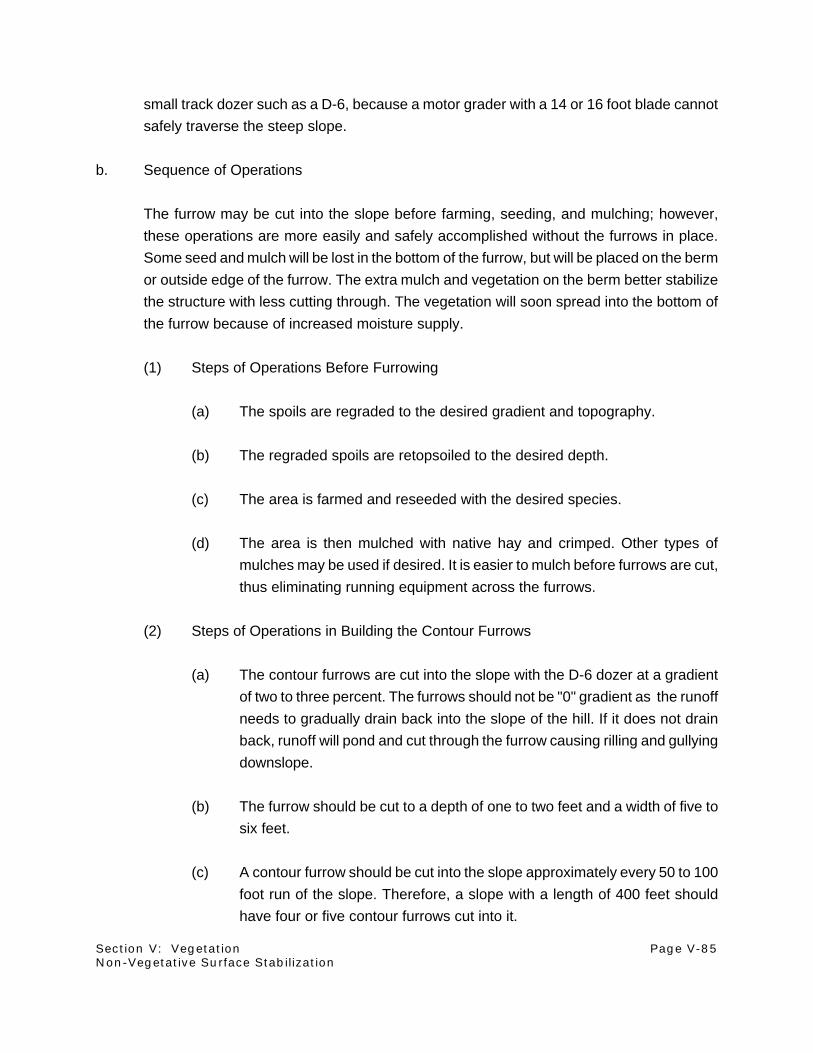
Section V: Vegetation Page V-85Non-Vegetative Surface Stabilization
small track dozer such as a D-6, because a motor grader with a 14 or 16 foot blade cannot
safely traverse the steep slope.
b. Sequence of Operations
The furrow may be cut into the slope before farming, seeding, and mulching; however,
these operations are more easily and safely accomplished without the furrows in place.
Some seed and mulch will be lost in the bottom of the furrow, but will be placed on the berm
or outside edge of the furrow. The extra mulch and vegetation on the berm better stabilize
the structure with less cutting through. The vegetation will soon spread into the bottom of
the furrow because of increased moisture supply.
(1) Steps of Operations Before Furrowing
(a) The spoils are regraded to the desired gradient and topography.
(b) The regraded spoils are retopsoiled to the desired depth.
(c) The area is farmed and reseeded with the desired species.
(d) The area is then mulched with native hay and crimped. Other types of
mulches may be used if desired. It is easier to mulch before furrows are cut,
thus eliminating running equipment across the furrows.
(2) Steps of Operations in Building the Contour Furrows
(a) The contour furrows are cut into the slope with the D-6 dozer at a gradient
of two to three percent. The furrows should not be "0" gradient as the runoff
needs to gradually drain back into the slope of the hill. If it does not drain
back, runoff will pond and cut through the furrow causing rilling and gullying
downslope.
(b) The furrow should be cut to a depth of one to two feet and a width of five to
six feet.
(c) A contour furrow should be cut into the slope approximately every 50 to 100
foot run of the slope. Therefore, a slope with a length of 400 feet should
have four or five contour furrows cut into it.

Section V: Vegetation Page V-86Mowing for Weed Control
E. Husbandry
1. Mowing for Weed Control
Section editor: Larry H. Kleinman Subsection author: Laurel E. Vicklund
~~~~~~~~~~~~~~~~~~~~~~~~~~~~~~~~~
Situation:
Annual weeds can present problems in newly seeded areas. Chemical control is costly and
sometimes not feasible. Mowing offers an economical option for weed control.
Special Considerations:
Areas seeded to permanent grass should be evaluated periodically during the first few growing
seasons. Noxious weeds and other problems need to be identified and dealt with as soon as they
develop.
Once permanent vegetation is seeded, treatment options for the area are limited so as not to affect
the bonding clock. Mowing to control annual weeds provides good results with low environmental
impact on the area, and does not restart the bonding clock. Mowing maintains a stubble cover, but
prevents seed set for the year and knocks back the weeds that take available moisture from the
developing grasses.
Description of Technique:
Annual weeds are a prevalent feature of reclaimed areas. They serve the function of shading small
grass seedlings, collecting snow, reducing wind erosion, and aid in the stabilization of the ground
against water erosion until the permanent grass seedlings are established. However, abundant
annual weed growth utilizes soil moisture and chokes out new seedlings.
During the first summer after permanent grass mixtures have been seeded, a rotary deck type
mower can be used to cut the annual weeds. This should be done prior to weed flowering and seed
production. The weeds usually have enough height to be cut by May or early June. If the year is
moist enough, the area may need additional mowing later in the summer. Multiple mowing reduces
the size of the windrow created.

Section V: Vegetation Page V-87
NOTES

Section V: Vegetation Page V-88Burning to Enhance Vegetation
2. Burning to Enhance Vegetation
Section editor: Larry H. Kleinman Subsection author: Laurel E. Vicklund
~~~~~~~~~~~~~~~~~~~~~~~~~~~~~~~~~
Situation:
Successful reclamation depends on moisture received during the year in the form of rain and snow.
Without adequate moisture, even with the best tillage and seeding techniques, reclamation will fail.
Often the failure is not immediately identified. By the time a seeding failure is noticed, the area can
be covered with too much vegetative matter to make drill seeding or hydroseeding possible. A firm
seed-bed already exists beneath the vegetative rubble; therefore, it is not advantageous to re-till
the area. Burning the vegetative matter removes the surface trash for reseeding to take place with
a minimum of seed-bed preparation.
Special Considerations:
State Air Quality officials may require a burning permit prior to burning activities. Burn days usually
must coincide with air sampling run days. Local county officials will also usually require notification
prior to burning an area.
Site specific safety regulations should be followed for a planned burn, and safety equipment and
pertinent safety personnel should be advised and on hand. Areas that have steep slopes may need
additional protection from erosion after the burn.
Techniques successful for burning to enhance vegetation are very site-specific. The Cordero Mine
has had good results from using these techniques. The size of the area will vary from site to site.
Do not start a fire larger than you feel you have the personnel and equipment necessary to
extinguish.
Weed seeds will not necessarily be destroyed by the fire, so additional weed control methods may
be needed. Mowing as weed control is economical, and does not have the environmental concerns
associated with chemical weed control. However, perennial noxious weeds cannot be controlled
by mowing and need aggressive treatment when found in reclamation.

Section V: Vegetation Page V-89Burning to Enhance Vegetation
Description of Technique:
Areas to be excluded from the planned burn should be identified. A plan should be developed to
ensure the burn will be contained in the identified area. Natural barriers work the best for a planned
burn. For example, roads, ditches, rock areas, or other areas devoid of vegetation work well as
natural barriers.
When possible, the burn should be planned around a planting season. Most burning is done in the
fall or spring, so this fits right in. The less time that elapses between the burn and reseeding, the
less chance for erosion to develop before the grass cover is adequately established.
Check the wind direction and velocity prior to starting the fire. Pick a time when vegetative cover
in the area is dried but regional burning is not banned. Start the fire in the corner of the area that
the wind is coming from, opposite from the corner of the barrier and perimeter of the area. In this
way, the wind will carry and spread the fire towards the barrier of the burn. An area seems to burn
best with a slight wind, however an excessive wind can spread the fire past the barriers and out of
control.
Once the fire has consumed the area, check to ensure that it is completely out. Extinguish any
areas that have not burned out. Some areas that had excessive trash cover may need extra
attention to ensure a complete burn and reduce the danger of fire spreading after the burn.
Interseed the area at the first available seeding window. Drilling should be done on the contour to
reduce erosion.

Section V: Vegetation Page V-90Husbandry Grazing
3. Husbandry Grazing
Section editor: Larry H. Kleinman Subsection author: Larry H. Kleinman
~~~~~~~~~~~~~~~~~~~~~~~~~~~~~~~~~
Situation:
There are certain circumstances under which livestock grazing can be used to affect changes in
the species composition of a revegetated stand once the vegetation has become established.
Annual bromegrasses are very difficult to control without plowing and refarming the field or utilizing
complete herbicidal control. Judicial use of late fall and early spring grazing by livestock has been
shown to decrease the amount of annual bromegrasses.
There may be older seeded stands that have a preponderance of introduced species that are
suppressing more desirable native species. Smooth bromegrass and crested wheatgrass often
begin spring growth several weeks before other cool season grasses and certainly before warm
season grasses. Heavy grazing in the early spring can cause a decrease in the early growing cool
season grasses and an increase in the later growing grasses.
Litter buildup can occur on revegetated areas that have not been grazed, burned, or hayed. This
buildup of litter will continue until the seeded species are suppressed, if no action is taken.
Special Considerations:
The livestock owner must be flexible in cooperating with the reclamationist. The reclamationist must
be able to bring the cattle onto the revegetation at just the right time and take the cattle off the
revegetation with only a day or two notice. The reclamationist must be on hand to determine when
the grasses desired for control are ready to be grazed and when the grasses desired for increase
begin active growth. The desired species should be dormant at the time of grazing.
Description of Technique:
Livestock grazing for the following three described purposes, annual bromegrass control,
introduced cool season grass suppression, and litter reduction, may and probably should take place

Section V: Vegetation Page V-91Husbandry Grazing
in concert with each other. It must be emphasized that the timing of grazing be flexible and that the
reclamationist be cognizant of the timing of plant growth. For additional information on grazing
practices, refer to the Postmining Land Use section of this handbook.
a. Annual Bromegrass Control
Annual bromes are considered to be winter germinators. If conditions are favorable during
early November, they will germinate and grow to a height of two to four inches before
cessation of growth for the winter. If they are grazed at this time, those individuals will not
continue growth to seed set the next spring. Cattle will readily graze the available green
forage and thus reduce the number of plants that will set new seed the next spring. The
dormant perennial grasses will not be damaged even by heavy grazing.
The annual bromegrasses will germinate earlier in the spring than any of the introduced or
native cool season grasses. If the annuals are grazed in the spring after growth has begun
and before the desired perennials begin growth, the weed crop for that year will be lost. If
the annuals are inhibited, the perennials will increase. A decrease has been noted in the
amount of annual bromes within two years by grazing in the early spring or late fall. The
cattle must be taken off the revegetation just as the desired perennial species begin
substantial growth (leaf height of one to two inches).
b. Introduced Cool Season Perennial Grass Control
Livestock grazing has been used to reduce the amount of introduced cool season grass
species in the revegetated stand, including crested wheatgrass and smooth bromegrass.
These two species generally initiate growth several weeks earlier in the spring than do the
native perennials. The livestock grazing should take place after the introduced grasses
have begun growth and before the native species have attained substantial growth (leaf
height of one to two inches).
c. Litter Reduction
Livestock grazing can reduce the amount of standing litter and break up the fallen litter in
a revegetated stand. The desirable species should be dormant at the time of grazing.
Grazing may take place at any time during dormancy from late summer to early spring. The
desired species will not be damaged by the heavy grazing necessary to reduce the amount
of litter. The grasses can be grazed to a stubble height of one to three inches with no
damage to the dormant plant. Enhanced growth will be noted the next growing season.

Section V: Vegetation Page V-92
NOTES

Section V: Vegetation Page V-93Vegetation Sampling
F. Monitoring
1. Vegetation Sampling
Section editor: Larry H. Kleinman Subsection author: Greg E. Jones
~~~~~~~~~~~~~~~~~~~~~~~~~~~~~~~~~
Situation:
Vegetation assessments of permanently reclaimed areas should be conducted at specified intervals
to document vegetation development, assess readiness for and effects of grazing on reclaimed
areas, and to document land uses.
Special Considerations:
Sampling methodology should be developed and agreed upon by the operator and regulatory
agency prior to initiation of data collection. Consistent methods should be used for baseline and
postmining sampling.
Description of Technique:
a. Delineation of Reclaimed and Study Areas
Each reclaimed area should be identified with a specific designation, so all activities relating
to its development and assessment can be recorded and documented. These designations
can correspond to mine site, year of topsoiling, area number (postmining vegetation type)
and sub-area linkage (non-contiguous/same treatment areas). If a permanently reclaimed
area is redisturbed (topsoil removed) or drastically altered (tilled under or completely
reworked), that portion (acreage) can be removed from the previous designation and/or
redesignated to reflect the alterations performed.
Since reclamation activities (acreages) vary from year to year, several similar, although not
contiguous, reclaimed areas can be combined to constitute one monitoring area. These
monitoring areas would preferably range from 50 to 100 acres in combined size.

Section V: Vegetation Page V-94Vegetation Sampling
During the bond release period, study areas may consist of combined reclaimed areas of
similar vegetation types, which may be at differing stages of development. These studies
can be summarized as a whole although individual sample locations should be tracked to
allow analysis of individual reclaimed areas.
b. Monitoring Plan Parameters
Each reclaimed area should be sampled for the following parameters at specified intervals
using those methods described below.
- % vegetation cover by species*
- % total vegetation cover (sum of all species)*
- % total ground cover (vegetation + litter + rock)*
- % bare ground*
- herbaceous production
- shrub density
- list of species observed during sampling
* % values are reported as absolute % cover
c. Sampling Methodology
Sampling methods should comply with those accepted by the appropriate regulatory agency
of your area. The methods discussed below are provided as examples and can be altered
to meet the desired sampling needs.
(1) Cover Data Collection
Cover data can be collected using the line transect/point intercept method. Sample
locations for cover are chosen by randomly selecting points within a grid of the
revegetated area. Grid intervals should not exceed 100 feet on the ground.
Randomly generated sample location coordinates should be plotted on a map and
located in the field by pacing from known features or land marks. Random numbers
between 1 and 360 should be generated to orient each transect. Sample locations
which encompass non-contiguous reclamation areas or varying vegetation types
should be consecutively numbered through each area or vegetation type to allow
individual or grouped analysis and comparison of the data collected. Sample hits
are taken at 1 meter intervals along the entire length of a 50 meter transect. These
first hit (50) data points will constitute the absolute cover values for one full sample
set. Additional hits at each meter mark may be recorded separately but not included

Section V: Vegetation Page V-95Vegetation Sampling
in absolute cover values for that particular transect. This multiple hit information can
be used to compile the overall plant list for the area and to qualitatively describe the
stratified vegetation cover within each respective revegetation area.
Cover by individual species should be collected for the 50 hits within each transect
and later combined into total vegetation cover. In addition, litter, rock, and bare
ground hits should be recorded and later combined into total ground cover.
Transects that exceed designated vegetation boundaries should be randomly
reoriented to be within the sampled vegetation area.
(2) Production Data Collection
Production data can be collected using one meter square plots. Sample locations
should be chosen by randomly selecting points within a grid of the revegetated
areas or by randomly locating plots along a cover transect in those areas monitored
for cover. Another method is to locate plots three feet perpendicular and three feet
to the right from the 50 meter end of a cover transect. Sample locations should
again be consecutively numbered for grouped or individual analysis as described
in the paragraph above on cover data.
Should the study areas include lands which will be grazed during the sampling
period, the use of vegetation exclosures will be required. The number and type of
exclosures should be sufficient to provide an adequate sampling area (one meter
square) and sample size (maximum samples within the grazed area).
Annual above-ground herbaceous biomass should be clipped by dominant species
and remaining minor species by lifeform. Full shrubs, succulents, noxious weeds,
and cushion plants should not be clipped. If annual grasses and/or annual forbs are
major community components, these life forms should be included in the sampling.
Clipped biomass should be placed in paper bags and dried in a forced air oven
(105°C for 24 hours). Samples should be weighted on an appropriate scale to the
nearest 0.10 gram and reported in grams per meter squared and pounds per acre.
Clipped samples less than 0.10 gram can be reported as trace samples. Average
bag weight must be calculated and subtracted from weighed samples.

Section V: Vegetation Page V-96Vegetation Sampling
(3) Shrub Density Data Collection
Shrub density data can be collected at random locations in conjunction with cover
transects on selected revegetation areas. All shrubs (full, half, or sub) should be
counted within 50 centimeters either side of the 50 meter cover transect (1 meter
by 50 meter belt transect). Shrub counts should be recorded by species and
reported as shrubs per meter squared and shrubs per acre.
In those reclaimed areas designated as a shrub mosaic or patch, the plot
configuration may vary in order to define the establishment and/or development of
the shrub component. When developed and productive stands of shrubs are defined
through periodic sampling, permanent transects and/or plots may be established to
document trends in shrub development and longevity.
(4) Plant Species List
A list of all plant species observed during cover and production sampling should be
recorded by life form and described by scientific and common names. The listing
can also include those species observed during the course of sampling although not
encountered within a specific cover transect or production plot.
Any federally designated threatened and endangered species, state plants of
concern, noxious weeds, and primary selenium indicator species observed should
be identified.
(5) Species Diversity
Relative cover percentages calculated from revegetation area cover data can be
used to evaluate the species diversity and richness of the area.
(6) Sample Intensity
The intensity or amount of samples collected within each revegetation area should
follow those requirements outlined by applicable regulatory requirements. Interim
monitoring of revegetated areas may require a set amount of samples per area,
dependent upon the size (acres) of the area. An example of sample size could be
ten random samples for each study/reclaimed area up to 100 acres in size, with one
additional sample for each ten acres of increased acreage within the area.

Section V: Vegetation Page V-97Vegetation Sampling
Should the study area require sampling to statistical adequacy, statistical testing
formulas outlined by the applicable regulatory agency should be used. At a
minimum, all sampling results should include the computed Z value and confidence
level achieved with the number of samples collected.
(7) Sample Frequency
Sampling of individual revegetation areas usually will not begin until the third
growing season following the year of permanent seeding. A schedule should be
developed which includes three sampling periods during the ten year minimum
bonding period. This schedule would serve as a minimum sampling frequency,
additional samples may be taken or substituted for determination of grazing
readiness and stocking rates or to document special treatments on specific areas.
d. Sample Data Analysis
All data collected should be analyzed and presented in a tabular format acceptable to the
applicable regulatory agency. Tables 1, 2, and 3 illustrate the results of cover, production,
and shrub density vegetation studies conducted on reclamation areas.
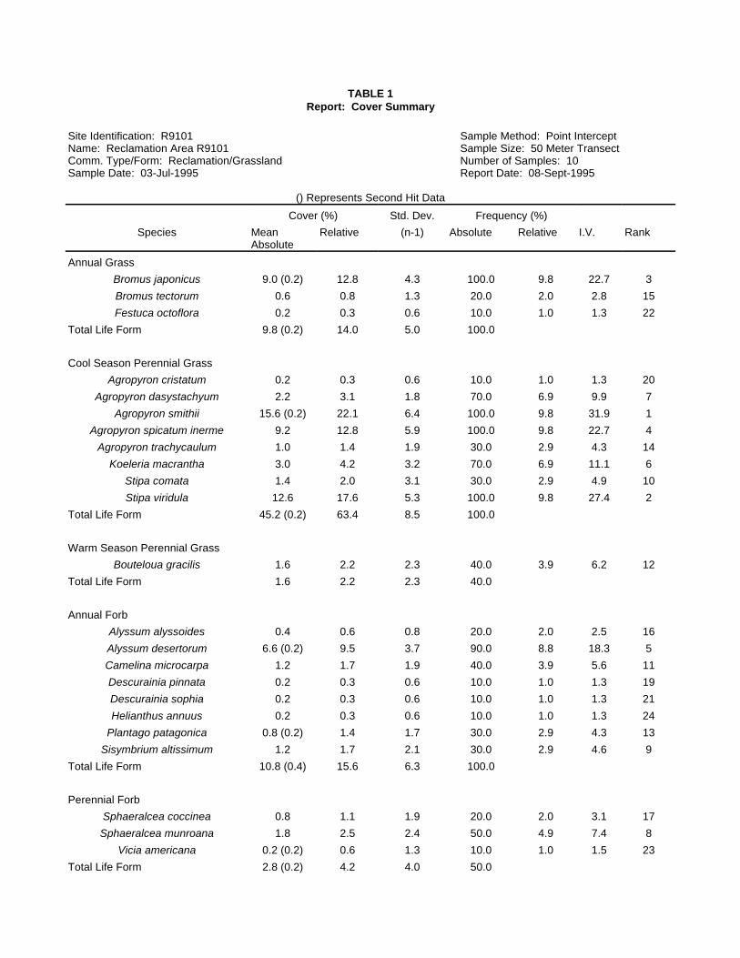
TABLE 1Report: Cover Summary
Site Identification: R9101 Sample Method: Point InterceptName: Reclamation Area R9101 Sample Size: 50 Meter TransectComm. Type/Form: Reclamation/Grassland Number of Samples: 10Sample Date: 03-Jul-1995 Report Date: 08-Sept-1995
() Represents Second Hit Data
Cover (%) Std. Dev. Frequency (%)
Species MeanAbsolute
Relative (n-1) Absolute Relative I.V. Rank
Annual Grass
Bromus japonicus 9.0 (0.2) 12.8 4.3 100.0 9.8 22.7 3
Bromus tectorum 0.6 0.8 1.3 20.0 2.0 2.8 15
Festuca octoflora 0.2 0.3 0.6 10.0 1.0 1.3 22
Total Life Form 9.8 (0.2) 14.0 5.0 100.0
Cool Season Perennial Grass
Agropyron cristatum 0.2 0.3 0.6 10.0 1.0 1.3 20
Agropyron dasystachyum 2.2 3.1 1.8 70.0 6.9 9.9 7
Agropyron smithii 15.6 (0.2) 22.1 6.4 100.0 9.8 31.9 1
Agropyron spicatum inerme 9.2 12.8 5.9 100.0 9.8 22.7 4
Agropyron trachycaulum 1.0 1.4 1.9 30.0 2.9 4.3 14
Koeleria macrantha 3.0 4.2 3.2 70.0 6.9 11.1 6
Stipa comata 1.4 2.0 3.1 30.0 2.9 4.9 10
Stipa viridula 12.6 17.6 5.3 100.0 9.8 27.4 2
Total Life Form 45.2 (0.2) 63.4 8.5 100.0
Warm Season Perennial Grass
Bouteloua gracilis 1.6 2.2 2.3 40.0 3.9 6.2 12
Total Life Form 1.6 2.2 2.3 40.0
Annual Forb
Alyssum alyssoides 0.4 0.6 0.8 20.0 2.0 2.5 16
Alyssum desertorum 6.6 (0.2) 9.5 3.7 90.0 8.8 18.3 5
Camelina microcarpa 1.2 1.7 1.9 40.0 3.9 5.6 11
Descurainia pinnata 0.2 0.3 0.6 10.0 1.0 1.3 19
Descurainia sophia 0.2 0.3 0.6 10.0 1.0 1.3 21
Helianthus annuus 0.2 0.3 0.6 10.0 1.0 1.3 24
Plantago patagonica 0.8 (0.2) 1.4 1.7 30.0 2.9 4.3 13
Sisymbrium altissimum 1.2 1.7 2.1 30.0 2.9 4.6 9
Total Life Form 10.8 (0.4) 15.6 6.3 100.0
Perennial Forb
Sphaeralcea coccinea 0.8 1.1 1.9 20.0 2.0 3.1 17
Sphaeralcea munroana 1.8 2.5 2.4 50.0 4.9 7.4 8
Vicia americana 0.2 (0.2) 0.6 1.3 10.0 1.0 1.5 23
Total Life Form 2.8 (0.2) 4.2 4.0 50.0

Site Identification: R9101 Sample Method: Point InterceptName: Reclamation Area R9101 Sample Size: 50 Meter TransectComm. Type/Form: Reclamation/Grassland Number of Samples: 10Sample Date: 03-Jul-1995 Report Date: 08-Sept-1995
() Represents Second Hit Data
Cover (%) Std. Dev. Frequency (%)
Species MeanAbsolute
Relative (n-1) Absolute Relative I.V. Rank
Perennial Shrub
Artemisia tridentata 0.4 0.6 0.8 20.0 2.0 2.5 18
Total Life Form 0.4 0.6 0.8 20.0
Total Stratified Vegetation Cover 71.6 100.0 6.8 100.0
Total Non-stratified Vegetation Cover 70.6 7.1
Litter 17.4 6.2 100.0
Rock 0.4 0.8 20.0
Total Ground Cover 88.4 5.1
Bare Ground 11.6 5.1 100.0
Total Cover 100.0 0.0
Species Abundance(number of species/sample)
10.2 1.9

TABLE 2Report: Production Summary
Site Identification: N8701ALL Sample Method: Random PlotsName: Reclamation Area N8701ALL Sample Size: 1.0 sq m.Comm. Type/Form: Reclamation/Grassland Number of Samples: 10Sample Date: 27-Jun-1995 Report Date: 08-July-1995
Species Mean Production(gm/sq.m)
MeanProduction
(lbs/ac)
RelativeProduction
(%)
Std. Dev.(n-1)
(gm/sq.m)
Annual Grass
Bromus japonicus 0.953 8.502 0.605 2.410
Bromus tectorum 0.650 5.799 0.412 1.598
Total For Life Form 1.603 14.302 1.017 4.008
Cool Season Perennial Grass
Agropyron cristatum 0.266 2.373 0.169 0.841
Agropyron dasystachyum 58.438 521.372 37.079 46.374
Agropyron riparium 0.341 3.042 0.216 0.782
Agropyron smithii 26.508 236.499 16.820 25.408
Agropyron spicatum 1.647 14.694 1.045 5.208
Bromus inermus 28.544 254.664 18.111 60.805
Stipa viridula 3.496 31.191 2.218 10.372
Total For Life Form 119.240 1063.834 75.659 38.081
Annual Forb
Alyssum alyssoides 0.721 6.433 0.457 2.280
Alyssum desertorum 3.848 34.331 2.442 4.195
Camelina microcarpa 4.591 40.960 2.913 8.777
Descurainia pinnata 0.053 0.473 0.034 0.168
Thlaspi arvense 0.615 5.487 0.390 1.502
9.828 87.683 6.236 14.228
Perennial Forb
Lithospermum incisum 0.077 0.687 0.049 0.243
Medicago sativa 17.094 152.509 10.846 33.778
Onobrychis viciaefolia 0.307 2.739 0.195 0.971
Ratibida columnifera 0.922 8.226 0.585 2.916
Sphaeralcea munroana 0.077 0.687 0.049 0.243
Vicia americana 0.154 1.374 0.098 0.487
Total For Life Form 18.631 166.222 11.822 33.259
Perennial Sub-shrub
Artemisia frigida 0.200 1.784 0.127 0.632
Ceratoides lanata 8.100 72.267 5.140 9.480
Total For Life Form 8.300 74.051 5.266 9.310
TOTALS 157.602 1406.092 100.000 62.542

TABLE 3Report: Density Summary
Site Identification: R9103 Sample Method: Transect PlotsName: Reclamation Area R9103 Sample Size: 50.0 sq m.Comm. Type/Form: Reclamation/Sagebrush Grassland Number of Samples: 5Sample Date: 27-Jun-1995 Report Date: 08-Sept-1995
Species Mean Number/Plot
RelativeDensity %
Std. Dev.(n-1)
Number/Plot
Mean(Number/sq.m.)
Mean(Number/Acre)
Perennial Shrub
Artemisia cana 42.800 12.3 43.8 0.86 3464.1
Artemisia tridentata 230.200 66.0 222.8 4.6 18631.7
Total For Life Form 273.000 78.3 263.0 5.46 22095.8
Perennial Sub-shrub
Artemisia frigida 19.000 5.5 19.3 0.38 1537.8
Ceratoides lanata 56.600 16.2 65.6 1.13 4581.0
Total For Life Form 75.600 21.7 53.7 1.51 6118.8
TOTALS 348.600 100.0 229.5 6.97 28214.7

Section V: Vegetation Page V-102
NOTES

Section V: Vegetation Page V-103Recordkeeping Practices
2. Recordkeeping Practices
Section editor: Larry H. Kleinman Subsection authors: D.G. Steward/Marlys M. Hansen
~~~~~~~~~~~~~~~~~~~~~~~~~~~~~~~~~
Situation:
The release of reclamation bonds depends on quantitative and qualitative reclamation success.
Evaluation of this success is meaningless without accurate and comprehensive records. These
records can be collected in a set of volumes to make a history of mine reclamation. The
Reclamation History is a database of revegetation practices, as well as monitoring and assessment
information, from the beginning of reclamation on a minesite.
Special Considerations:
The Reclamation History database expands year by year, serving as a definitive source of data
regarding date of permanent reclamation, revegetation practices, revegetation assessment and
sampling, topsoil fertility, backfill geochemistry, and postmining land use. Revegetation practices
and vegetation cover by species through time constitute a large part of the data array. An
organized and retrievable Reclamation History, such as can be found in this database, provides
many opportunities for data analysis and interpretation.
In addition, Reclamation History information provides feedback for current practices and thus allows
continual improvement of reclamation practices. Revegetation monitoring and research can include
investigations into the effects of soil type and fertility on reclamation species, the success of various
reclamation species, the effects of postmining land use, the impact of mulching, the success of
shrub pads, the success of various methods of sagebrush seeding, and the success of direct-haul
topsoil.

Section V: Vegetation Page V-104Recordkeeping Practices
Description of Technique:
a. Date of Permanent Reclamation
History of reclamation in a given area can be considered to start at the time regraded
backfill is topsoiled and the topsoil prepared for revegetation. Backfill replacement and
grading is considered a part of the process. Topsoil placement and final surface preparation
can be selected to define the date of permanent reclamation, because (except in very rare
circumstances) topsoil replacement and final surface preparation are only done once. In
contrast, revegetation may be, and often is, conducted over a span of years. Drought, pest
infestations, and seed failures all contribute to multiple revegetation efforts.
Many Reclamation Histories also begin at the time of regrading the backfill. Both dates,
regrading and topsoiling, should be a part of the Reclamation History.
b. Revegetation Practices
An element which comprises a significant component of the database is the revegetation
practices for all permanently reclaimed units. These practices are presented by season and
by year. Revegetation activities are conducted in the spring and the fall; therefore, each
year has two seasons for which information is available. This data can be presented in the
same database format shown in Figure 1 of the subsection entitled "Preparing a
Revegetation Package". Maps for both seasons of each year, showing the location of all
revegetation units, are included.
One way of dividing permanent revegetation is into the following three categories:
(1) Permanent Revegetation
Permanent revegetation practices are recorded any time seeding is conducted with
the intention that the seeding will serve as the basis for postmining land use.
Seeding of grains may occur for agricultural uses such as pastureland and
cropland. Thus, seeding of annual grains can be considered, in some cases,
"permanent".

Section V: Vegetation Page V-105Recordkeeping Practices
(2) Functionally Permanent Revegetation
Functionally permanent revegetation practices are those that occur when the initial
intention was for long-term temporary seeding, but where time has shown that the
seeding will serve as the basis for postmining land use. The most typical example
of functionally permanent revegetation is revegetation of road ditches and rights-of-
way that were initially seeded for stabilization, but where the road has been
incorporated into the postmining land use plan and the vegetation has become very
well established. There is often little likelihood in such a case that these areas will
be re-disturbed.
(3) Husbandry Practices
Husbandry records can be included with permanent and functionally permanent
practices so that a record of such husbandry exists. Husbandry in an area does not
re-initiate the bond time period, and is thus fundamentally different from permanent
and functionally permanent practices.
c. Revegetation Assessment and Sampling
Data collected in revegetation research and monitoring conducted at a mine are also
included in the Reclamation History. The purpose of revegetation monitoring is to prove
establishment of desired vegetation as well as the progress that has been made toward
postmining land use goals. As a result of monitoring, modifications and additions can be
made to revegetation practices in order to enhance the achievement of those goals
Geographic locations of vegetation sample locations can be identified using State Plane
coordinates. Maps of sample locations can be included in the Reclamation History. Figure
1 gives a sample table that can be used to document vegetation sampling results (figure
follows text). This table is expanded, year by year, to cover all types of vegetation found
and all areas sampled.
d. Topsoil Fertility
State regulations and the mine permit may require that topsoil fertility be assessed where
topsoil has been stockpiled for more than one year. Fertility samples are collected in the
backfill in those areas over which stockpiled topsoil has been spread. The information
collected through the assessment program can also be used to determine fertilization rates.

Section V: Vegetation Page V-106Recordkeeping Practices
Topsoil fertility data is presented in a spreadsheet which covers all aspects of sampling.
Data is added to the spreadsheet as it is collected each year.
e. Backfill Geochemistry
Before topsoil can be replaced, the suitability of the top four feet of backfill must be
assessed; thus, backfill geochemistry is another component of the Reclamation History.
Geochemical information is collected at intervals from backfill. The cumulative backfill
database is presented in the Reclamation History in a spreadsheet that can be updated as
data is collected each year.
f. Postmining Land Use
Any postmining land use practices employed by the mine can be summarized in a history.
These practices may include wildlife use, production of grains, haying, or livestock grazing.
For techniques on these practices, refer to the Postmining Land Use section of this
handbook.

Section V: Vegetation Page V-107Recordkeeping Practices
FIGURE 1
Vegetation Sampling
Unit or Area or Treatment
OBS or sample number
Sampler
Date of sampling
Easting
Northing
Aspect
Slope
Quadrant size
Cover (1) or Production (2)
% Total desirable vegetation
% Total vegetation
% Total litter/rock (or ground)
% Total bare soil
% Total cover
% Bare soil
% Litter
% Rock
Agropyron dasystachyum
Agropyron intermedium
Agropyron smithii
Agropyron trachycaulum
Alyssum desertorum
Artemisia tridentata
Astragalus cicer
Atriplex canescens
Avena fatua
Bouteloua gracilis
Bromus inermis
Calamovilfa longifolia
Ceratoides lanata
Descurainia richardsonii
Elymus junceus
Helianthus annuus
Lupinus pusillus
Medicago sativa
Melilotus officinalis
Onobrychis vicifolia
Orysopsis hymenoides
Plantago patagonica
Poa Pratensis
Polygonum convolvulus
Sphaeralcea coccinea
Stipa viridula
Thlaspi arvense
Tragopogon dubius
Vicia americana

Section V: Vegetation Page V-108
NOTES

Section V: Vegetation Page V-109Electronic Document Management
3. Electronic Document Management in Mining
Section editor: Larry H. Kleinman Subsection author: Greg E. Jones
~~~~~~~~~~~~~~~~~~~~~~~~~~~~~~~~~
Situation:
The following discussion is provided to describe the application of Electronic Document
Management (EDM) to electronically capture, store, distribute, annotate, display and print the
extensive data required by the Surface Mine Control and Reclamation Act of 1977 (SMCRA),
which was previously available only in paper format.
Special Considerations:
The EDM system design may include integration of software which would be compatible with the
Technical Information Processing System (TIPS) developed by the Office of Surface Mining and
State regulatory agencies.
Description of Technique:
a. Electronic Document Management
Along with on-going efforts to increase mining productivity, operators can also develop
effective methods and technology which provide efficient means of fulfilling the
requirements associated with SMCRA. Through the use of EDM, operators can realize an
increase in manpower efficiency along with improved quality, repeatability and transferability
of data collected, reported, and analyzed in State and Federal permit documents.
b. EDM Primary Components
The following discussion provides a brief description of four components commonly used
to transfer or exchange information relating to permit applications and/or reports.

Section V: Vegetation Page V-110Electronic Document Management
DBMS
IngresSite and Sample
Tabular Data
GIS
ARC / INFOCartographic Data
Graphical Information
CAD
Autocad
FIGURE 1
ELECTRONIC DOCUMENT MANAGEMENT
Reports
Text andTables
Electronic Output
Text FilesASCI Files
Presentation Maps
Electronic Output.DXF Files.DWG Files.GRA Files
ARC Export Files
HydrologyAdjudication
VegetationTopsoil
ReclamationOverburden
Cultural ResourcesWildlife
Relational
Database
Interface
ScannedMaps
DigitizedMaps
DigitalOrtho Photos

Section V: Vegetation Page V-111Electronic Document Management
(1) Computer Aided Drafting (CAD)
Computer-aided drafting software applies computer graphics technology to
automate manual drafting techniques. The primary use of this application is for the
design, drafting, and display of graphically oriented information.
(2) Geographical Information System (GIS)
Geographical Information System software is designed to support the capture,
management, manipulation, analysis, modeling and display of spatially referenced
geographic data.
(3) Database Management System (DBMS)
Database Management System provides an organized set of data that allows
flexible query and manipulation of tabular data by selecting portions of the data set
for further calculation, analysis, reporting, or data exchange.
(4) Word Processing (WP)
Word Processing software is utilized for all textual portions of permit applications.
Through submission of electronic text files, technical personnel may access
separate portions of the application at the same time, resulting in more expeditious
permit reviews.
c. Individual EDM Topic Applications
The following applications describe how an EDM system can be utilized to prepare permit
documents in electronic format for submittal to a regulatory agency.
(1) Baseline Topsoil Surveys
GIS applications can be used to store, illustrate, and analyze specific topsoil
information (soil type, soil depth, mapping unit) according to geographical
boundaries and parameters defined in the baseline study. Through a process of
overlaying or clipping a topsoil polygon coverage with other polygon coverages,
detailed reports are created to describe, for example, the extent (acres) of each soil
type and the quantity (yards) within a proposed permit boundary.

Section V: Vegetation Page V-112Electronic Document Management
This application can be used to develop reports which summarize the projected total
amount of topsoil available for salvage within the disturbance limits of the mine plan,
for use in determining an average salvage and reclamation replacement depth.
Additional analyses can be performed to define area and volume by individual
disturbance year, for mass balance tables in the mine plan section.
(2) Baseline Vegetation Surveys
GIS applications are used to store, illustrate and analyze specific vegetation
information (vegetation types) according to geographical boundaries and
parameters defined in the baseline study. Through the same processes described
for topsoil surveys, detailed reports can be created to describe the extent (acres)
of each vegetation type within a defined polygon (permit boundary, disturbance
area, or study area).
The DBMS is also utilized to store raw baseline vegetation data from surveys,
provide printed reports of selected criteria, and provide a statistical baseline for
comparison of pre- to post-mining vegetation data at the time of bond release.
(3) Legal Description and Ownership
Regulatory requirements call for the legal description of all lands within and
surrounding a permit area. Through GIS applications, specific legal or ownership
data are associated with known tracts of land, and spatial relationships can be
established to determine the exact acreage of a permit area, by legal identification
(ID) (section, township, range), or ownership (surface or mineral) by owner, address
or legal ID.
(4) Wildlife
Both CAD and GIS systems can be applied to the protection of wildlife resources.
Electronic data are used to accurately map and define the extent of important
wildlife habitats within and adjacent to mining operations. Habitats such as
wetlands, big game ranges, game bird breeding areas and raptor nest locations are
documented electronically so they can be referenced to mining activities for
appropriate mitigation actions.

Section V: Vegetation Page V-113Electronic Document Management
(5) Reservoir Designs
Through the use of CAD/GIS topographic maps (five foot contours) for the mining
area, reservoir sites are selected, construction contours drawn and merged with
existing topography, and stage volume tables are created using CAD routines.
Design information including existing topography with reservoir design contours can
be placed on an exhibit with stage volume tables, cross sections, plan view, and
associated water level annotation.
(6) Overburden Suitability
Surface mining operations can use maps developed through CAD/GIS applications
to determine overburden suitability. These maps show suitability of overburden (by
individual suitability parameter) according to the criteria described in each mine
site's approved permit. These same data can then be provided to the state
regulatory agency in electronic format.
(7) Hydrology
Hydrologic data, including surface flow, static water levels for wells, and
geochemistry data can be stored in the DBMS. Data can be directly loaded through
a custom window application or batch loaded from a file provided by contract
laboratories. Use of the DBMS allows for production of reports with user defined
parameters, statistical analysis for selected data, creation of graphs to monitor
trends, and electronic transfer of data to regulatory agencies for compilation into
larger database applications.
(8) Revegetation/Reclamation
All aspects of an EDM system can be used in the storage, tracking, analysis and
reporting of revegetation/reclamation activities. GIS applications can be used to
define reclaimed areas (area ID, extents, seed mixture, year of topsoiling, year of
seeding...). Through the various attributes assigned to individual areas, detailed
reports and maps can be created based on user defined variables.
The DBMS can be used to store interim monitoring vegetation data collected for
each area. This information can be entered through a custom windowing application
or batch loaded from files prepared by vegetation contractors. Various outputs are

Section V: Vegetation Page V-114Electronic Document Management
available through the vegetation DBMS system which include: cover, production,
and density reports (raw data and summaries); plant species summary by area
(which describes species observed, first year observed and number of years
observed); and statistical summary reports for data collection parameters (standard
deviation, actual sample size, computed adequate size, computed Z value, and
confidence level achieved).
Reclamation exhibits illustrating backfill and reclamation progression can be
prepared in CAD along with associated backfill mass balance tables. WP is utilized
to textually describe each action associated with the reclamation plan along with
tabular illustrations of each mine site's seed mixtures. Through application of the
EDM, practically all portions of the Reclamation Plan can be provided to the
regulatory agency in electronic format.
(9) Textual Information
WP software is used for all textual material included in permit documents. This
software should be compatible with that used by the regulatory agency reviewing
the document. Examples include text changes made in bold type to better define
changes, and pages submitted with consistent pagination and revision dates.
d. Summary
An EDM system as described above can provide a powerful tool for use in complying with
State and Federal regulatory requirements. Considerable cost and manpower savings can
be realized, along with increased technical knowledge and analytical capabilities,
consistency of information, and enhanced transfer of complex scientific data.

Section V: Vegetation Page V-115References
G. References
Buckingham, Frank. 1984. Fundamentals of Machine Operation - Tillage. Deere and Company
Service Training, Department F, John Deere Road, Moline, Illinois, 61265. 368 pp.
Breece, H. Edward and Harold V. Hansen. Fundamentals of Machine Operation - Planting.
Deere and Company Service Training, Department F, John Deere Road, Moline, Illinois,
61265. 185 pp.

Section V: Vegetation Page V-116
NOTES

SECTION VI
POSTMINING LAND USE
Section Editor: D. G. StewardSection Editor: D. G. Steward
table of contents

Section VI: Postmining Land Use Page VI-i
TABLE OF CONTENTS
SECTION VI: POSTMINING LAND USE
A. Introduction . . . . . . . . . . . . . . . . . . . . . . . . . . . . . . . . . . . . . . . . . . . . . . . . . . . . . VI-1
B. Grazing . . . . . . . . . . . . . . . . . . . . . . . . . . . . . . . . . . . . . . . . . . . . . . . . . . . . . . VI-3
1. Early Implementation of Postmining Land Use;
Grazing as Husbandry . . . . . . . . . . . . . . . . . . . . . . . . . . . . . . . . . . . . . . . . VI-3
2. Establishing and Controlling a Grazing Program on the Mine Site;
Initial Planning . . . . . . . . . . . . . . . . . . . . . . . . . . . . . . . . . . . . . . . . . . . . . . . VI-7
3. Establishing and Controlling a Grazing Program on the Mine Site;
Writing the Grazing Contract . . . . . . . . . . . . . . . . . . . . . . . . . . . . . . . . . . . VI-15
4. Establishing and Controlling a Grazing Program on the Mine Site;
Implementation . . . . . . . . . . . . . . . . . . . . . . . . . . . . . . . . . . . . . . . . . . . . . VI-19
5. Creating Livestock Pastures . . . . . . . . . . . . . . . . . . . . . . . . . . . . . . . . . . . VI-23
6. Water Sources for Livestock . . . . . . . . . . . . . . . . . . . . . . . . . . . . . . . . . . . VI-32
7. Moving Livestock . . . . . . . . . . . . . . . . . . . . . . . . . . . . . . . . . . . . . . . . . . . . VI-43
8. Vegetation Quality for Grazing . . . . . . . . . . . . . . . . . . . . . . . . . . . . . . . . . VI-51
9. Timing of Grazing . . . . . . . . . . . . . . . . . . . . . . . . . . . . . . . . . . . . . . . . . . . VI-55
10. Grazing, Wildlife, and Wildlife Habitat . . . . . . . . . . . . . . . . . . . . . . . . . . . VI-63
C. Wildlife . . . . . . . . . . . . . . . . . . . . . . . . . . . . . . . . . . . . . . . . . . . . . . . . . . . . . VI-67
1. Forage Enhancement for Wildlife . . . . . . . . . . . . . . . . . . . . . . . . . . . . . . . VI-67
2. Water Resources . . . . . . . . . . . . . . . . . . . . . . . . . . . . . . . . . . . . . . . . . . . VI-69
3. Rockpile Design and Construction . . . . . . . . . . . . . . . . . . . . . . . . . . . . . . VI-72
D. References . . . . . . . . . . . . . . . . . . . . . . . . . . . . . . . . . . . . . . . . . . . . . . . . . . . . VI-80
E. Citations . . . . . . . . . . . . . . . . . . . . . . . . . . . . . . . . . . . . . . . . . . . . . . . . . . . . . VI-81

Section VI: Postmining Land Use Page VI-ii
NOTES

Section VI: Postmining Land Use Page VI-1Introduction
A. Introduction
Section editor: D.G. Steward
~~~~~~~~~~~~~~~~~~~~~~~~~~~~~~~~~
I. Federal Regulatory Requirements
Land use management at surface coal mines is unique amongst environmental
management activities because postmining land use is the centerpiece of the governing
environmental statute for coal, the Surface Mining Control and Reclamation Act (SMCRA)
of 1977 (95th Congress, Public Law 95-87, 1987). This act states:
"Each reclamation plan... shall include... a statement of: the use which is
proposed to be made of the land following reclamation, including a
discussion of the utility and capacity of the reclaimed land to support a
variety of alternative uses and the relationship of such use to existing land
use policies and plans...; a detailed description of how the proposed
postmining land use is to be achieved and the necessary support activities
which may be needed to achieve the proposed land use."
The language, while sometimes ignored by regulator and regulated alike, clearly directs the
focus of mine environmental activity towards utility of the landscape following mining. Thus,
postmining land use is the culmination of surface coal mining and environmental
management activities at each mine. Many state statutes and regulations reflect the
Federal emphasis on postmining land use.
2. Land Use Types
While provisions are made in both Federal and State regulations for postmining land uses
different from premining land use, considerable difficulties can be encountered in making
a land use change. As a result, in Wyoming, postmining land use is typically the same as
premining land use. Land uses are specifically defined in state regulations.
In practice, however, there is no one single postmining use of the land. For example, while
the single most common postmining land use in Wyoming is grazingland, that land use
includes use by wildlife. Other postmining land uses that have been or may plausibly be
identified include fish and wildlife habitat, recreation, and industry. Residential use, while
possible, is not likely to be common.

Section VI: Postmining Land Use Page VI-2Introduction
3. Wyoming Land Use Types
As the "Cowboy State", Wyoming has a long heritage of interaction between the landscape,
people, and livestock. Wyoming also has the particularly rich and precious resources of
high wildlife and low human population densities. Postmining land uses in this state should
thus conserve and enhance both this heritage and these resources. Similar to other
technologies, livestock grazing is continuously evolving. Grazing practices have benefited
from extensive research, from active application and modification of technology, and from
increasing awareness of the interaction between man's activities and the environment.
4. Technological Advances and Utility of Land Use Implementation
Part of the challenge of establishing a postmining grazingland is incorporating the
technological and environmental advances in grazing, and designing the system in such a
way that the benefits of technology can be maintained. Relatively small changes in the
design of a grazingland can adapt the land for use by wildlife as well. To meet this
challenge, an ongoing dialogue between the mine, the regulator, and the postmining land
user, along with an active program of testing and development should be maintained during
mining.
Failure to actively address postmining land use needs during the active mining and bonding
period will only result in difficulties during the time bond release is sought. In addition, the
benefits of a well-designed grazing program to reclamation are many, and include
diversification of the vegetation, increased rate of soil development, reduction of
undesirable species, and enhancement of wildlife habitat.
5. Resources for Postmining Land Use Development
Local ranchers, concerned citizens, the Soil Conservation Service, the County Extension
Agent, the State University, and the State Land Quality authority are all sources of input and
information on the development and implementation of the specifics of the postmining land
use plan. In addition, the history of the region, including both successful and unsuccessful
business and agricultural pursuits, can provide valuable information as the postmining land
use plan is developed.

Section VI: Postmining Land Use Page VI-3Early Implementation of the Postmining Land Use; Grazing as Husbandry
B. Grazing
1. Early Implementation of the Postmining Land Use;
Grazing as Husbandry
Section editor: D.G. Steward Subsection authors: D.G. Steward/R.S. Shinn
~~~~~~~~~~~~~~~~~~~~~~~~~~~~~~~~~
Situation:
Utilization of a livestock grazing program for postmining land use provides many benefits. Proper
grazing management is a powerful tool in the development and maintenance of grassland and
prairie ecosystems, and can positively affect the health and reproduction of many types of grasses.
Practices that improve rangelands also improve wildlife habitat, aiding in the re-establishment of
wildlife in postmining landscapes. A grazing program aids in demonstrating postmining land use
as well as collecting information necessary for bond release.
Special Considerations:
Agreement must be made between the regulatory agency, the landowner, and the mining company
before grazing can commence on permanent revegetation. Permission may also be required from
the U.S. Forest Service, the State, the Bureau of Land Management, or other regulatory agencies.
Description of Technique:
a. Benefits to Early Implementation of the Postmining Land Use During the Bonding Period
Implementation of the postmining land use during the bonding period can have many
benefits, regardless of the type of land use. These benefits include the opportunity to:
evaluate the implementation of the use to ascertain if reclamation processes are adequate
to support that use; coordinate activities with the regulatory agency to ensure their
familiarity with the selected land use and its particular implementation; derive income from
the implementation of the land use; and improve the postmining landscape cost effectively
and without re-starting the bond clock.

Section VI: Postmining Land Use Page VI-4Early Implementation of the Postmining Land Use; Grazing as Husbandry
(1) Grazing as Husbandry
Improving the postmining landscape without resetting the bond clock falls into the
category of husbandry. Not all postmining land uses can be considered husbandry
practices. However, in the State of Wyoming, it has been agreed (WDEQ-LQD
Guideline No. 14, 1991) that grazing can be used as a husbandry practice.
There is no prohibition on grazing being used as a husbandry practice immediately
following re-establishment of vegetation cover in the postmining landscape. The
regulations usually require that permanent revegetation be protected by fencing
or other means from being destroyed by livestock during the first two years
following planting. In addition, again for permanent revegetation, agreement must
be made between the regulatory agency, the landowner, and the mining company
that grazing can be commenced. In some cases, this also requires the permission
of another regulatory agency, most typically the U.S. Forest Service, the State, or
the Bureau of Land Management.
(2) Grazing for Landscape Enhancement
Grazing, which is often viewed as detrimental to the landscape, is a very powerful
tool for amending and improving the landscape. Proper grazing practices have been
documented in both formal and informal studies to provide the following benefits:
(a) Stimulation of root growth, which provides individual plants with increased
drought and disease protection;
(b) Maintenance of optimum litter levels, which leads to maximum water
retention in postmining soils and minimum runoff, thus decreasing erosion;
(c) Removal of excess biomass, which improves plant growth and reproduction,
and leads to increased palatability and decreased senescence of individual
plants;
(d) Creation of surface microsites, which provides locations for germination and
establishment of new individuals and creates surface roughness to enhance
water retention;

Section VI: Postmining Land Use Page VI-5Early Implementation of the Postmining Land Use; Grazing as Husbandry
(e) Seed dispersal and colonization from adjacent native areas, which leads to
diversity and elimination of an agricultural appearance; and
(f) Weed suppression, which is usually required by State law, and can assist
in hastening natural successional processes.
The keys to grazing as an agent of landscape enhancement are discussed in the
following sections, which include: Establishing and Controlling a Grazing Program
on the Mine Site; Creating Livestock Pastures; Water Sources for Livestock; Moving
Livestock; Vegetation Quality for Grazing; Timing of Grazing; and Grazing, Wildlife,
and Wildlife Habitat.
(3) Grazing as a Source of Income
Finally, the mining company can realize increasing amounts of income from ongoing
use of the postmining landscape, providing financial verification for the company's
position that the postmining land use has been achieved. This income, while small
in relation to the income to be derived from mining, can significantly defray
revegetation costs over time, thus leading to an overall reduction in mining costs.
b. Grazing Management
Grazing is integral to the development and maintenance of grassland and prairie
ecosystems, and to the health and reproduction of many types of grasses. Proper grazing
management can and must take the place of the large herds of herbivores that formerly
roamed the Great Plains. Proper grazing management will ensure the preservation of open
space and vegetation for prairie wildlife habitat. Practices that improve rangelands also
improve wildlife habitat, thereby assisting the mine in reaching another important goal, that
of re-establishing wildlife in postmining landscapes.
Grazing is simply a means of managing the grassland resource. In truth, for the dedicated
landscape manager, grazing is but one (albeit the most effective one), management tool.
This does not imply that good livestock handling is not an important skill for the
implementation of the grazing program -- far from it. The program will fail without expert
stock management. But the resource that is the centerpiece of the program is the
landscape itself. Proper management of the landscape will ensure that livestock production
goals are optimized.

Section VI: Postmining Land Use Page VI-6Early Implementation of the Postmining Land Use; Grazing as Husbandry
For the mining company, developing a grazing program early in the reclamation cycle can
reap benefits in addition to those outlined above. Because postmining land use is central
to SMCRA, the mining industry must unequivocally demonstrate that the approved
postmining land use has been achieved. A long established program will buttress, with a
continuous grazing history, the information that must be collected in the two years previous
to seeking bond release. An established grazing program will make the collection of the
bond release information easy because the data can be collected within the framework of
a well-established and smoothly functioning program.

Section VI: Postmining Land Use Page VI-7Establishing and Controlling a Grazing Program on the Mine Site; Initial Planning
2. Establishing and Controlling a Grazing Program on the Mine Site;
Initial Planning
Section editor: D.G. Steward Subsection authors: D.G. Steward/R.S. Shinn
~~~~~~~~~~~~~~~~~~~~~~~~~~~~~~~~~
Situation:
While there may be no regulatory requirement for a specific grazing plan each year, a detailed
written plan for grazing will significantly improve program implementation. The annual plan should
include computation of grazing days by pasture, and address mineral and supplementation
requirements. The plan should include a map and a grazing sequence. The map should be kept
current with respect to permanent fence, gate, and water locations. This grazing plan should be
developed at least three months before implementation of the annual program is anticipated, and
should be carefully reviewed with the grazier. Grazing sequencing can be quite complicated,
particularly when husbandry goals are being incorporated. The Environmental Engineer (EE)
should allow plenty of time for the development of the annual plan, and should seek review by his
or her manager, by security personnel, and by safety personnel.
Special Considerations:
Selecting the proper grazier can be very difficult, but is extremely important to the success of the
program. The grazier must exhibit enthusiasm, flexibility and cooperation, and genuine care and
concern for the livestock. Remember - the program is likely to be a showpiece item during mine
tours.
Description of Technique:
a. Defining Program Goals
Before other aspects of a grazing program can be established, the EE or specialist who has
been given charge of the program should carefully define the goals of the program.
Consideration should be given to all the potential benefits discussed in the subsection

Section VI: Postmining Land Use Page VI-8Establishing and Controlling a Grazing Program on the Mine Site; Initial Planning
entitled "Early Implementation of the Postmining Land Use; Grazing as Husbandry".
Thought should be given to the specific application of these concepts to the particular mine
site. Consideration should also be given to the information discussed below, as well as to
the other topics in this section.
Paramount consideration should be given to the degree of support, both financial and
programmatic, that can be expected from mine management. The desires of management
should be incorporated in the program. Some managers will be extremely interested in the
program and will provide many ideas and much support. Other managers may be less
supportive. If the EE is unsure about long-term commitment to the program, the best advice
is to develop a program that is simple to terminate. The stability of the program will be of
paramount importance to the grazier, as will be discussed below, and will affect both the
cost and timing of the program.
Once a program is developed and is working properly, it should be highlighted through
education and tours as part of the overall mining effort. This will aid in maintaining support
for the program and will also provide a focus for employee pride and interest in the
company. However, beware that a poorly managed and executed program will do more
harm than good. Thus, the EE charged with implementing the program must be thoroughly
invested in the success of the program.
b. Selecting a Grazier
Unless a mining company is willing and able to allocate significant resources in terms of
manpower and money to a ranch-type program, the prudent EE will develop a good working
relationship with a grazier in order to implement a grazing program. While the EE must take
complete responsibility for the grazing program, the EE typically can allocate only limited
time to the actual implementation of the program. Thus, the grazier is the EE's greatest
asset in developing a postmining grazing program.
Selecting a grazier can be extremely difficult. In ranch country, practically everyone you
meet claims to be an expert on livestock and grazing, and many of these "experts" are so
mired in the way things have always been done that the EE will continually battle with them
over every aspect of the program. The EE must locate a grazier who is enthusiastic and
cooperative, who is willing to give more than lip service to the goals of the program, who
is flexible and easy to work with, and who truly exhibits care and concern for his or her
livestock. Without question, the EE should visit the operations of a prospective grazier and

Section VI: Postmining Land Use Page VI-9Establishing and Controlling a Grazing Program on the Mine Site; Initial Planning
watch the grazier in operation. When negotiating with a prospective grazier, the following
issues should be given careful consideration:
(1) Flexibility
When the EE begins discussion of the program goals, does the prospective grazier
immediately discount the goals with his or her ideas of how it won't work, how
impractical the goals are, or how to do it differently? This is a paramount warning
signal that this grazier will not make a success of the program.
(2) Condition of Grazier's Current Operations
What is the condition of the range on the lands where the prospective grazier is
currently grazing? Pastures as bald as an egg, with well-established trails along
fences and water, do not bode well for the success of this grazier on your reclaimed
ground.
Are the grazier's operations neat and tidy? If his or her own property is dilapidated
and unsightly, you can bet these characteristics will carry over onto yours. Be sure
to check the fences -- poor fencing indicates a grazier who will not have the interest
and enthusiasm to properly implement your program.
(3) Livestock Condition
When visiting the grazier's current operations, were the livestock calm and healthy
looking (beware of a grazier whose livestock run from him!!). You don't need to be
an expert to recognize skinny, sorry animals.
If at all possible, observe the prospective grazier as he or she works livestock. Is he
or she calm, efficient, and careful with the stock? Lots of yelling and running are
sure indicators of a grazier who will not work well in your program.
(4) Self Motivation
Does the grazier have a plan for the necessary stock numbers and manpower
needs of your program? The grazier should be able to produce a coherent plan.

Section VI: Postmining Land Use Page VI-10Establishing and Controlling a Grazing Program on the Mine Site; Initial Planning
Finally, while a "know-it-all" cowboy is the opposite of what the EE needs, a
prospective grazier that can and will contribute ideas and thoughtful attention to the
goals of the program will be a valuable resource to the EE. A self-motivated grazier
who is invested in the goals of the program will make or break the program.
A final word of advice: Often, for political reasons or simply out of convenience, the mining
company will want to hire the neighbor next door or the rancher who currently is leasing
lands from the company that have not yet been mined. This can certainly be a success, but
the prudent EE will resist this idea if it runs contrary to program goals. Active selection of
an appropriate grazier can sometimes overcome the inertia of using the neighboring
rancher. On the other hand, don't fail to investigate the neighboring rancher. For
convenience and ease of program implementation, nothing beats an adjacent operator.
c. Deciding on the Species and Type of Livestock
Many species of livestock are available for a grazing program, and the temptation to
develop an unusual program can be strong. More than one mine manager has asked for
buffalo on the reclaimed land. Before the EE selects the species of livestock for his or her
grazing program, all subsections in this section should be carefully reviewed. The selection
of the species of livestock should follow naturally on the heels of an initial program review.
Most especially, the EE should consider:
(1) Is there a grazier available who operates the species of livestock under
consideration, and are the livestock themselves easily available?
(2) What are the front-end costs for facilities, especially water, fencing, and handling
for the species of livestock under consideration?
(3) How easy is it to handle and move the species of livestock under consideration?
(4) Do the livestock under consideration offer any health or safety risks to the mine
workforce?
As with any endeavor, the program with the greatest possibility of success is that with the
fewest opportunities for failure. Simply put, a mine in cattle country is probably best off
running cattle. Sheep should also be strongly considered. Whatever the choice, it is prudent
to save the more esoteric grazing programs for the time when the grazing program itself
Section VI: Postmining Land Use Page VI-11Establishing and Controlling a Grazing Program on the Mine Site; Initial Planning
is well established. Those buffalo may prove to be more expensive and more difficult to
handle than first imagined.
Most of the discussions that follow in this section on postmining land use will center on
cattle grazing. Cattle are extremely easy to manage. They are readily available and have
predictable grazing and behavior patterns. The novice program manager will have a very
good chance of success if cattle are selected as the grazing animal. However, the selection
process does not end with the species of livestock. Following the selection of livestock
species, the type of livestock must be selected. The types of livestock include cow-calf
pairs, dry cows, weanlings, yearling heifers, yearling steers, and bulls. Each has its
advantages and disadvantages.
Of all the animal types, dry cows or bred cows are the easiest to manage. A dry cow is a
cow without a calf. Dry cows and bred cows are well-behaved and easy to move. However,
unless the grazier is running a cull cow program, dry cows and bred cows are usually only
available in the fall and winter. In the spring it is the cow-calf pair that is typically available.
Young calves can be difficult to move, even with their mothers, and frequent movement
may negatively affect their gain. Cow-calf pairs are best run on reclaimed land after the
calves are two months old.
Weanling calves are not a good choice for reclaimed land grazing. They can be skittish and
may become ill. Once these animals have reached yearling status they are good grazing
candidates. Yearling steers are frequently used for grazing programs because there is no
worry about accidental breeding. Steers will also gain weight more rapidly than heifers.
Steers can be friskier than heifers and more difficult to train. Steers can also be afflicted
with water belly, a urinary tract problem that is difficult to treat and often fatal.
Spayed yearling heifers are docile and easy to move; however, they will not show the
weight gain of steers. Yearling heifers for breeding are often very profitable, but their
management includes the added management of the reproductive season. The confined
pastures typical of the reclaimed grazing program make for excellent breeding pastures.
The EE should be cautious of the grazier with a long breeding season. Bulls, whether with
cow-calf pairs or with heifers, can get restless once breeding has been completed, and
the good grass and small pastures typically found on reclaimed land will shorten the
breeding season.
The final selection of animal type should be based on the needs of the grazier and the
security of the grazing situation on the mine. Ease of handling should also be a major

Section VI: Postmining Land Use Page VI-12Establishing and Controlling a Grazing Program on the Mine Site; Initial Planning
consideration. While there is a great deal of talk about the relative merits of animal breeds,
this decision is best left to the grazier. The relative docility of Herefords or Salers, for
example, is not something on which the EE needs to pass judgement. Occasionally, mine
management will desire one breed over another, longhorns over Angus, for example. If
this can be accommodated, there is no reason not to do it, providing the proper grazier
can be located.
d. Facilities and Specialty Equipment for the Grazing Program
Running cattle during the spring, summer, and fall requires very little in the way of
equipment. Of paramount importance is water, which is discussed in greater detail
elsewhere in this section. Following water in importance is fencing, which is also discussed
as a separate subsection. Depending on the time of year, fly bags or some method of fly
control will be necessary. The EE should discuss the specifics of fly control with the grazier,
keeping in mind that proper pasture rotation will reduce fly problems. Typically, the grazier
will supply fly control.
When grazing reclaimed ground, because of the uncertainties of reclaimed land
geochemistry, it may be wise for the mine to supply mineral supplementation for the cattle.
It would be foolish to generate claims regarding animal health simply because the grazier
scrimped on minerals for the stock and then blamed it on the condition of the mine soils.
There is no need to conduct a soil sampling program for mineral deficiencies. The local
feed store can suggest a full-range mineral that will be adequate for the needs of the
program. The EE should confirm his or her selection with the grazier prior to obtaining the
mineral.
Devices for actually feeding mineral to the cattle will be needed. Many commercial devices
are available for this purpose, but portability is the primary concern. Plastic 55-gallon drums
cut in half lengthwise are inexpensive and are difficult for the cattle to tip over. Using two
holes drilled in each end, halves can be equipped with a stout string and easily pulled from
one paddock to another. The halves can be connected in trains of six or seven with no
difficulty. The trains can also be used to feed supplement. The mine may supply mineral
and mineral feeders, unless otherwise desired by the grazier.
The final consideration for facilities is some reliable means to load and unload the cattle.
If the cattle are properly trained and are being properly managed, the load-out facilities and
processes for delivering and removing the herd as a whole, bulls for breeding, or sick and
treated animals can consist of portable panels and a stock trailer. For large numbers of

Section VI: Postmining Land Use Page VI-13Establishing and Controlling a Grazing Program on the Mine Site; Initial Planning
animals being loaded and unloaded from a stock truck, a portable load-out chute will be
necessary. As in all aspects of cattle work, proper handling of the animals will reduce the
need for special facilities. Typically, the grazier supplies the load-out facilities.
The EE should carefully discuss and agree upon the facilities needed for the program with
the grazier well before the program is implemented. The grazing contract should contain
all of the agreements in writing.
e. Obtaining Concurrences and Permissions
Initiating a grazing program on reclaimed ground can require many concurrences and
permissions. The EE should allow at least three months, and better six, for obtaining the
necessary concurrences and permissions. It is usually necessary to incorporate the general
program elements in the mine permit. Specifics of the program and permission for first time
grazing must be discussed and agreed upon with the regulatory agency and the landowner.
Other regulatory agencies may be involved in the program, particularly the U.S. Forest
Service and the Bureau of Land Management.
The mine manager and department manager must concur on the need for the program.
Many times the program must be coordinated with the company land agent, or the person
otherwise responsible for managing company lands. The safety manager should review and
approve the program. It is also wise to bring operations personnel into the loop early in the
process so their comments can be incorporated in the program. Comments and
suggestions from security personnel are also very useful.
It is often wise to obtain the advice of the local County Agent, the Soil Conservation
Service, any local Conservation Districts, local Game and Fish personnel, and any wildlife
consultants for the property. Integrating the grazing program with wildlife use of the
reclaimed surface will achieve the best possible results for your program.

Section VI: Postmining Land Use Page VI-14
NOTES

Section VI: Postmining Land Use Page VI-15Establishing and Controlling a Grazing Program on the Mine Site; Writing the Contract
3. Establishing and Controlling a Grazing Program on the Mine Site;
Writing the Grazing Contract
Section editor: D.G. Steward Subsection authors: D.G. Steward/R.S. Shinn
~~~~~~~~~~~~~~~~~~~~~~~~~~~~~~~~~
Situation:
The grazing contract must be written in a manner whereby the Environmental Engineer (EE) in
charge of the program can exercise maximum control. All aspects of the grazing agreement must
be addressed in the contract.
Special Considerations:
Writing the grazing contract by the grazing day provides the best means to control consumption
of the resource as well as a payment schedule that accurately reflects that consumption. When
calculating fees, consideration must be given to the amount of work expected of the grazier.
Grazing day calculations should be reviewed each time the contract is renewed.
Description of Technique:
a. Writing the Grazing Contract and Establishing Expectations for the Grazier
There are three ways of writing a grazing contract: by the acre, by the animal, or by the
grazing day. By the acre is the method apparently most simple, but it is almost impossible
to retain control over animal movement and the timing of grazing if the grazier is paying for
the property by the acre. The grazier will be inclined to graze as long and as hard as
possible to obtain the best value for his dollar.
While more controllable than an acreage contract, a grazing contract by the animal, or more
specifically, the animal-unit, is fraught with similar hazards. In this case, the grazier may be
inclined to overstock the property or conversely, underuse the resource.

Section VI: Postmining Land Use Page VI-16Establishing and Controlling a Grazing Program on the Mine Site; Writing the Contract
(1) Payment by Grazing Days
The method whereby the EE can exercise most control over the grazier is through
payment by grazing days. Payment by the grazing day forces the EE to make a
realistic evaluation of the grazing resource, provides a means to control
consumption of that resource, and provides a payment schedule that accurately
reflects consumption of the resource. Calculation of the number of grazing days
available is a major controlling variable of the grazing program and should be
carefully researched. Grazing days are calculated as follows:
Grazing Days = ((AFP/Acre * PU) / (FC * EAU) * AA * 365)
(a) AFP/Acre = Annual Forage Production per Acre
This number can be estimated from baseline permit data, revegetation data,
or the County Agent. Dry forage is the variable commonly used.
(b) PU = Palatability * Utilization
Palatability for reclaimed forage is usually fairly high because it is mainly
grasses. A typical number is 80 percent (0.8), but the number can drop to
50 percent (0.5) or less if the vegetation is dry, old, or weedy. A reasonable
estimate is 75 percent (0.75), but this should be evaluated case-by-case.
Utilization is the amount of the forage resource the EE wants consumed.
This number depends upon the time of year, and can be higher when the
vegetation is dormant than when it is actively growing. Utilization of actively
growing vegetation is typically 55 percent (0.55). Utilization of dormant
vegetation can be as high as 70 percent. A reasonable estimate is 50
percent (0.5), but this should be evaluated case-by-case.
(c) FC = Forage Consumption
When animals have free choice feed, forage consumption can range up to
35 or 40 dry pounds per day. Winter feed rates are usually calculated at 20
pounds per day. A reasonable estimate is 30 pounds per animal unit, but

Section VI: Postmining Land Use Page VI-17Establishing and Controlling a Grazing Program on the Mine Site; Writing the Contract
this should be evaluated case-by-case. Be sure this number is in the same
units (pounds or kilos) as the Annual Forage Production.
(d) Equivalent Animal Units (EAU)
1.0 AU = Cow-calf pair
0.5 AU = Weanling calf
0.7 AU = Yearling animal
0.8 AU = Dry or cull cow
1.5 AU = Bull
These numbers can be modified to some degree at the discretion of the EE,
with agreement from the grazier. The designation is time-sensitive, and is
based on the probable forage consumption of the animal. Consultation on
the proper assignment of animal unit values can be obtained from the
County Agent, the Conservation District, or the Soil Conservation Service.
(e) AA = Available Acreage
This is the acreage that is available for grazing. Be sure to remove acres
that are disturbed or otherwise in use.
b. Renewing the Contract
Grazing day calculations should be reviewed each time the contract is renewed, and any
pertinent knowledge gained from grazing the reclaimed ground should be used to modify
the formula where appropriate.
Cost per grazing day can be extremely variable, but should be consistent with long-term
lease and grazing agreements in the area. Because the grazier is being asked to operate
in non-typical ways, it is usual to grant a slightly reduced grazing fee. In 1994, a reasonable
grazing day fee on reclaimed lands in Campbell County could vary between $0.35 and
$0.50 for non-snow conditions. Consideration for the amount of work expected of the
grazier must be incorporated in the grazing day fee, as must local grazing fees.

Section VI: Postmining Land Use Page VI-18Establishing and Controlling a Grazing Program on the Mine Site; Writing the Contract
c. Payment Adjustment
When grazing days are used as the basis for the grazing agreement, the grazier can adjust
animal numbers and timing of grazing at his discretion. One cow for 100 days and 100
cows for one day equate to the same number of grazing days. However, the goals of the
grazing program must be considered when adjustments are desired. With grazing days,
payment adjustments can easily be made for animal loss or removal. Provisions should be
made in the contract for removing animals from the leased area in case of drought. The
contract should also address any absolute time limits that may be placed on the program.
For example, it may only be possible to graze from May to September. These constraints
should be clearly stated.
The contract should address all other aspects of the agreement, including facilities and
equipment, the need for Mine Safety and Health Administration (MSHA) training for the
graziers, whether or not four-wheelers or horses can be used on the property, and the
obligation of the grazier to fulfill the requirements of the grazing contract. The initial
condition of the property and who will be responsible for fence repair and water facilities
should also be included, as should the frequency at which the grazier intends to check the
stock, and the response time for gathering strayed animals. Contract language should
otherwise follow standard legal format for land use agreements. Maps or exhibits may be
needed to complete the contract.
The terms of the contract are extremely important. The grazier will always desire maximum
stability in the contract. Typically, however, a grazing contract is for one year. This gives
the EE a straightforward route to extricate himself or herself from the contract, if necessary.
In addition, it gives both the EE and the grazier the opportunity to negotiate price changes
based on market conditions. After a good working relationship is established with the
grazier, the contract period may be extended.

Section VI: Postmining Land Use Page VI-19Establishing and Controlling a Grazing Program on the Mine Site; Implementation
4. Establishing and Controlling a Grazing Program on the Mine Site;
Implementation
Section editor: D.G. Steward Subsection authors: D.G. Steward/R.S. Shinn
~~~~~~~~~~~~~~~~~~~~~~~~~~~~~~~~~
Situation:
Developing a grazing program on reclaimed lands can be time consuming. However, the rewards
will far outweigh the difficulties. The Environmental Engineer (EE) in charge of the project must be
given the support and resources to conduct a successful program. When this occurs, the program
can be an ongoing source of satisfaction to all involved.
Special Considerations:
The successful grazing program should be continually growing. The program will expand as more
reclaimed land becomes available, and improve as the successes and failures of each year are
applied to the following year.
Description of Technique:
a. Training and Education
Training and education of the EE, the grazier, mine site employees, mine management, and
regulatory personnel will all contribute to program success. When possible, both the EE
and the grazier should be exposed to different grazing programs, and both should keep
current on grazing literature. Records should be kept of the annual grazing plan, and the
successes and failures of each year should be discussed and applied to the following year.
Mine site employees should be kept informed of the goals and the specifics of the program
each year. Mine management must definitely be kept aware of the successes and setbacks
of the program.

Section VI: Postmining Land Use Page VI-20Establishing and Controlling a Grazing Program on the Mine Site; Implementation
The EE should plan to write progress reports for the regulatory agency, and memos for the
workforce and management. Multi-media presentations and tours are a great way to obtain
program support. A photographic record of the program is also very useful, particularly
when requesting bond release.
b. Expanding the Program
Because reclaimed lands are continually expanding, the grazing program will also
continually expand. Planning for expansion will depend on program goals and should be
discussed well in advance with the grazier, who may need to supply additional animals. In
addition, the EE must budget both time and money for fencing and water additions, and
contact the regulatory agency before expanding onto formerly ungrazed lands.
The grazing program will eventually become a major focus of the reclamation effort, and
will reap many rewards for the company. It is important, therefore, to spend the time
needed to continually update and improve the program, and to monitor to ensure that
program goals are being met. The program must be responsive to the needs of the
landscape.
c. Livestock Tips for the Environmental Engineer
While it is unreasonable to expect every EE to be an expert in range and livestock
management, there are a few key items that can go a long way toward ensuring the
success of a grazing program. First and foremost, take the time to check the pastures
occasionally, at least once a week during the grazing season. If the mine site has security
people, they are often willing to check the stock for you every day. However, you or the
security people are not, repeat not a substitute for the grazier. Look for the following:
(1) The Development of Trails
The development of trails is a surefire sign that the livestock are remaining in the
pasture too long. The EE should expect some temporary degradation of the pasture
around the water source. With proper management this will disappear during the
next growing season. However, beware of distinct trails from all corners of the
pasture to the water or along the fences. Livestock should be removed from a
pasture immediately before these trails develop. It is the responsibility of the grazier
to perform this task and he must be responsive to the concerns of the EE.

Section VI: Postmining Land Use Page VI-21Establishing and Controlling a Grazing Program on the Mine Site; Implementation
(2) Animal Health
Scan the herd for animals with droopy ears, snotty noses, sore feet, or sluggish or
irregular behavior. If this is observed, contact the grazier immediately. Most sick
animals can easily be treated if they are identified early. While herd health is not the
responsibility of the EE, a dead animal laying out on the reclaimed ground is not
good publicity for anyone. However, the EE should refrain from the temptation to
work directly with the grazier's stock. This can lead to uncomfortable relations with
the grazier and liability for the EE.
(3) Ample Water and Minerals
Do the animals have enough water and is that water cool? Water stress very often
forces the animals to search for better water, and escaping animals on the minesite
are a headache no one needs. While in the paddock, check the supplements, if any,
that have been put out for the animals. Lack of bloat block in a pasture with lots of
alfalfa can lead to disaster.
(4) Fencing
Take a quick look at the fences in the pasture. Any wire that is down should lead to
a call to the grazier.
(5) Strayed Animals
Occasionally, despite everyone's best efforts, livestock will stray from the paddock.
This can be minimized by good stock handling and proper pasture management.
However, the EE should have a pre-arranged plan for this situation. Typically, mine
site personnel will notify Security of the situation and Security will contact the grazier
directly. Make sure a procedure for stray livestock is developed, is in writing, and
has been properly communicated to everyone.

Section VI: Postmining Land Use Page VI-22
NOTES

Section VI: Postmining Land Use Page VI-23Creating Livestock Pastures
5. Creating Livestock Pastures
Section editor: D.G. Steward Subsection authors: D.G. Steward/R.S. Shinn
~~~~~~~~~~~~~~~~~~~~~~~~~~~~~~~~~
Situation:
To a large extent, the grazing program is controlled by the pasture plan. The Environmental
Engineer (EE) should spend plenty of time developing the plan, and take into consideration the
advice of many. The pasture design must support the goals of the program while maintaining
maximum flexibility and growth potential in the system.
Special Considerations:
As in all other aspects of a grazing program, the prudent EE will take the time to develop a
reasonably detailed plan of pasture locations. The pastures should be mapped, and each year the
new plan for pasture rotation should be placed on the map, along with any pasture upgrades. The
date the pasture is first brought into the rotation is a useful piece of information to have on the
pasture map. Unfortunately, it is easy to let the pastures grow helter-skelter, only to find out one
year that there is no adequate map of the grazing facility. Don't succumb to the temptation to leave
the map upgrade for "later in the year".
Description of Technique:
a. Pasture Size
Pasture size is of great importance, and is very dependent on the number of animals and
the timing of grazing. Calculations related to pasture size are discussed in further detail in
the subsection entitled "Timing of Grazing". Husbandry goals such as removal of biomass
and alteration of the surface are greatly affected by pasture size. The general rule is, the
smaller the pasture, the better. However, small, permanently fenced pastures can be
prohibitively expensive, and have a nasty habit of being disturbed by unforecast mine
activities such as road building or tank installation. Pastures are always a compromise
between goals, budget, and convenience. Nonetheless, the size of the pasture is a powerful

Section VI: Postmining Land Use Page VI-24Creating Livestock Pastures
grazing tool, and its value is well worth any extra effort needed to optimize the pasture
design.
Central to the definition of pasture size is the concept of uniform application of grazing
pressure. Pastures should be designed to receive uniform grazing pressure. The other,
equally important concept, is timely removal of grazing pressure. Pasture size must support
both of these concepts.
When herd effect is important, the best practice is to have as many animals on the ground
as there is grass available for them. This usually means large numbers of animals and
small pastures. To achieve this, a good practice, particularly in the initial stages of the
program, is to establish a few permanent perimeter fences and subdivide the interior of the
pasture with electric fence. Once the EE has an understanding of the grazing system, it
may then be possible to permanently subdivide some of the larger pastures.
It is important to keep in mind that the livestock are being used to manage the grass
resource, not that the grass resource is being sacrificed for the convenience of the
livestock. Thus, it is often necessary, particularly on reclaimed ground, to set up pastures
specifically designed to minimize a weed problem, trample down excess vegetation, or
break up crusted soils. These objectives are legitimate, and can be very successful. In such
cases, grazing intensity should be managed carefully to ensure condition loss does not
occur to livestock.
b. Pasture Shape
A circular pasture on flat ground is the theoretically ideal pasture shape because there are
no corners or irregularities to diminish the uniform application of grazing pressure. Except
in irrigated situations, a circular pasture is neither reasonable nor desirable. However, the
concept of uniform application is relevant under any condition. Thus, to the extent possible,
pastures should be as equal as possible in all dimensions, and with as few corners and tight
spots as possible. Extremely rough terrain is not likely to be a consideration on reclaimed
ground, but the EE should avoid long skinny pastures and pastures with more than six
sides.
c. Location of Supplements, Including Water
Keeping in mind the principle of uniform application of grazing pressure, supplements
should be evenly distributed about the pasture to minimize over-utilization of certain

Section VI: Postmining Land Use Page VI-25Creating Livestock Pastures
areas. Supplements such as minerals and fly control devices are attractants. Their use
can be optimized by placing them away from water to draw the stock away from watering
areas, which tend to be overused. Attractants should not be placed in areas that tend to
become trails, for example, along fence lines. This will only lead to faster and more
permanent trail development.
Placing supplements next to the water is almost always an unbearable temptation for the
grazier. It is easier for the grazier, and he or she can be sure the livestock are finding the
supplements. Remember, however, that supplements are attractants. The livestock will find
them. Remember also that the livestock are out in that pasture 24 hours per day. Curious
as livestock are, it is extremely unlikely that they will fail to completely explore every square
inch of the pasture. Do not succumb to the grazier's tendency to place supplements close
to the water. It is likely that the EE will need to keep a close eye on this as it is contrary to
all program goals.
d. Adjacency
Another consideration in developing a pasture plan is isolated pastures. Unless isolated
pastures are desired for special purposes such as for bulls outside of the breeding season,
for horses that are being used in the program, or for sick pens and recovery pastures, they
should be avoided. Part of the planning program is to connect all the pastures to the
maximum extent possible. This will certainly minimize the possibility of animals getting loose
during pasture moves and will reduce the workload for all concerned.
e. Type of Fencing
Next to water, and, in reality, a far distant second in importance to water, is the type of
fencing to be used on reclaimed pastures. Fencing should never take the place of adequate
pasture, stock, and water management in controlling livestock. A properly trained herd
inside properly managed pastures will need very little to restrict them to the pasture. Fences
are a poor substitute for good water and good management. On the other hand, loose stock
on the mine site are a very real safety threat, so the issue of fences must be diligently
addressed. Fences designed to be the ultimate barrier between livestock and active mine
areas should be well constructed and well maintained.
The EE must constantly be aware of the needs and plans of the mine when developing a
fencing plan. It is almost certain that fences will be installed in areas that will later be

Section VI: Postmining Land Use Page VI-26Creating Livestock Pastures
needed for other purposes. Minimize this to the extent possible by working with
Engineering, Operations, and Construction.
(1) Wildlife
Careful consideration should be given to wildlife when constructing fences for
livestock. Even the minimum possible amount of fencing can represent a barrier to
wildlife. State Land Quality or Game and Fish guidelines should be followed for
fence construction, particularly with respect to spacing between the wires and
installation of a smooth wire on the bottom.
Another wildlife consideration is exclusion fencing. Exclusion fencing is used to
manage and defer grazing in wetlands and riparian areas. While complete exclusion
is not usually necessary, these areas should not be grazed during wildlife breeding
seasons, and the timing of grazing of these areas must be carefully managed. For
more information, see the subsection entitled "Fencing Practices and Wildlife".
(2) Permanent Perimeter Fence
Where fences will be the ultimate barrier between livestock and active mine areas,
fence construction should follow State guidelines. Using gaucho wire and stays will
reduce the need for posts. However, be warned that gaucho wire, a lighter gauge
and springier type of barb wire than conventional barb wire, is difficult to work with,
and graziers and fencing contractors may go to great lengths to convince the EE of
its undesirability. Field tests have shown this wire to resist snow burden and be
more resistant to breakage than conventional barb wire. It is a fencing tool that
should be given careful consideration.
Figure 1 shows a permanent perimeter fence design that has worked well in many
locations. The figure includes information on stays, post depths, deadmen, and
construction that should be considered and tailored for the particular location.
Where fences will not be the ultimate barrier between livestock and active mine
areas, a three-wire perimeter fence is perfectly acceptable for cattle. Figure 2 shows
a three-wire fence design that has worked well in many locations. Three-wire fence
is also a good fence to put in if there is a chance the fence may be moved or
removed. In such cases, the less fence, the better.

Section VI: Postmining Land Use Page VI-27Creating Livestock Pastures
(3) Gates and Braces
There are as many ways to construct gates and braces as there are fencing
contractors. Work out an acceptable procedure for your situation. Keep in mind that
contractors tend to skimp on brace construction, so good construction specifications
are absolutely necessary, or your fence will not last. Figures 1 and 2 both contain
suggestions regarding gates and braces (figures at end of text). When building
gates, remember two things: it is difficult to have too many gates, and never try to
push livestock uphill to a gate, especially a gate that is not equipped with some kind
of a trap or funnel.
(4) Electric Interior Fence
Electric fencing is a fantastic livestock management tool. It also has serious
drawbacks. However, it is unsurpassed in providing portability and flexibility in the
management program. It is good to use electric fence as a temporary interior fence
and to micro-manage grazing utilization. Electric fence is also useful for moving
animals (more on this under "Moving Livestock"). However, there are numerous
caveats to the use of electric fence.
Livestock must be trained to respect electric fences previous to being introduced
to electric fence as the sole means of livestock control, particularly on the mine.
Typically, training consists of no more than placing the cattle in a small pasture for
a day or two, and then fencing across it with electric fence. The animals will test the
fence and then learn to avoid it of their own accord, in a stress-free, familiar
environment. Animals should be trained to move into electrically fenced areas by
being called and caked. This technique is discussed in greater detail under "Moving
Livestock". A few days of this type of training will ensure obedient and docile
animals on the minesite.
Never use electric fence as a management tool in situations where the animals are
likely to be running away from something or otherwise stressed. If sufficiently
frightened or stressed, livestock will go through an electric fence, causing poor
training and considerable trouble for the grazier.
Electric fencing is made more simple with good equipment and a four-wheeler.
Patience is a valuable asset in using electric fence, as the wire can be easily
tangled. A four-wheeler can be a real timesaver when installing and removing

Section VI: Postmining Land Use Page VI-28Creating Livestock Pastures
electric fence. Use top quality equipment, especially posts. Economy posts will
deteriorate rapidly in strong sunlight, causing inconvenience for the grazier. Use a
large lunch cooler to hold the battery out in the field. A one-piece cooler rather than
a cooler with a separate lid is the best type.
Be sure to buy a good fence tester, and be sure to take the time to give the fence
a good ground. Once the stock are conditioned, very little is needed in the way of
electric fence -- usually two wires, and sometimes only one, will be sufficient.
After the grazing season is over, take the time to maintain and repair the
equipment. Store the equipment in a dark, dry place to ensure maximum equipment
life, and don't forget to take that battery out of the cooler.
When installing electric fence to subdivide permanent perimeter fences, give
thought to how the livestock will be moved. Usually three fence lines are needed to
maintain two paddocks -- one for the livestock to be in and one to move them into.
Following initial set-up, the back wire can be leap-frogged ahead to form the next
pasture. It is usually best to run the electric fence over the water tank. In this way,
the water will need to be moved only every other pasture. More detail on this is
discussed in the subsection "Water Sources for Livestock".
Electric fencing and pronghorn antelope are a real problem. Because antelope are
so skittish, they will panic and run through an electric fence. There are no good
solutions (and many people have tried to find one!!) for this except to allow the
pronghorn to acclimatize to the fence, to keep fence lengths reasonably short and
out of pronghorn travel paths if possible, and to plan to check and repair the fence
frequently.
In the long run, as the grazing program evolves and becomes stable, it is likely that
the use of electric fence can be minimized. Water management can be a good
substitute for electric fence. However, if there is any possibility that you will use
electric fence as a management tool, take the time to train or re-train your stock
before starting them in the mine site pasture rotation. Two days of work prior to
initiating the grazing program will save many headaches.

Section VI: Postmining Land Use Page VI-29Creating Livestock Pastures
FIGURE 1
SPECIFICATIONS: Permanent Fence
Fence
Construct a four-strand wire fence, using 15-½ gauge wire. The top three strands will be barbed wire and the
bottom strand smooth. Posts are set 20 feet apart, with wire stays between every post. Wood posts are to be
placed every fifth post.
Braces
To be placed every quarter-mile, at cross fences, the bottoms of draws, and other locations as specified by
the EE. A deadman will be placed at all corner and gate braces. The deadman will be tied to the base of a
vertical brace post and extend 3 feet into the ground on an angle with the brace cross-wire. The minimum
dimensions of the deadman will be 1 foot by 4 feet. Metal or treated wood can be used as a deadman.
(Note A - see figure) Brace should be constructed of 7 foot by 6 inch diameter uprights, with a 6 foot by 4 inch
diameter cross-post, securely nailed to the uprights at each end with at least three 40d spikes. Cross-posts
can be wood or metal.
(Note B - see figure) To construct brace wires, twist two 15-½ gauge wires together. Place 15-½ gauge wire
in a loop with ends securely spliced and wires stapled to the post on three sides. Use a fence stretcher to
stretch wire before twisting. Twist resulting wires to form a taut tie.
Stretch Gates
24-foot stretch gates will be placed every half-mile and wherever fences meet, or as specified by the EE. Four
stays must be used in each gate.
General Requirements
All staples holding wire, except in the braces, will be loose enough to allow play in the wire during changes
in temperature.
Line posts and cross brace posts will be 6-½ feet by 4 inch diameter. Brace uprights will be 7 feet by 6 inch
diameter. All wood posts must be fully pressure treated lodgepole pine, ponderosa pine, or douglas fir. Steel
posts must be 5-½ foot "T" posts, C.F. & I. Silver Tip or equal.
Staples will be not less than 9-gauge bright, and two inches long.
Earthen fill around wood posts must be tamped and compacted unless the post is driven directly into the
ground.

Section VI: Postmining Land Use Page VI-30Creating Livestock Pastures
FIGURE 1 continued

Section VI: Postmining Land Use Page VI-31Creating Livestock Pastures
FIGURE 2
SPECIFICATIONS: 3-Wire Temporary Perimeter Fence
Fence
Construct a three-strand wire fence using 15-½ gauge barbed wire. Fence dimensions; bottom wire 18 inches
off the ground, with second and third wires 12 inches above the wire below it.
Braces
To be placed every quarter-mile, at cross fences, the bottom of draws, or other locations as specified by the
EE.
Construct braces with 5-½ "T" post and "Wedge Lock" 45° fasteners. Install a cross brace from the top of the
corner post to the base of the support post. On an inline brace, install cross braces, as described, both
directions from the middle post. When a brace is installed, tie incoming fence wires to the corner or middle
post of the brace.
Stretch Gates
Construct 24-foot stretch gates where specified by the EE. Use four stays in each gate. Gate posts should
be wood posts 4 inches in diameter and cut to the same height as the brace post next to it. Fasten gate latch
to the brace post next to the gate. Ten inches is the maximum permissible gap between the brace and the
gate post. Install "Wedge Lock" braces on both sides of the gate.
General Requirements
M Set line posts thirty feet apart, with a wire stay between every post.
M Use certified steel "T" posts for the line posts and corner gate braces, C.F. & I. Silver Tip or equal,
set in the ground at least to the top of the footer.
M Use 15-½ gauge barb-wire.
M Twist steel post clips securely, but allow play to remain in the wire.
M Set wood 7 foot by 6 inch round posts on both sides of water gates and construct a dead man away
from the water. Tie water gate only to stand-off and construct steel post braces with "Wedge Lock"
on both sides of the gate. Use stays as needed in water gates.
M Earthen fill around wood posts must be tamped and compacted unless the post is driven directly into
the ground.

Section VI: Postmining Land Use Page VI-32Water Sources for Livestock
6. Water Sources for Livestock
Section editor: D.G. Steward Subsection authors: D.G. Steward/R.S. Shinn
~~~~~~~~~~~~~~~~~~~~~~~~~~~~~~~~~
Situation:
Nothing is more important to livestock than water sufficient in both quantity and quality. Lack of this
resource can cause more serious problems than deficiencies in other resources, and thus should
be a primary focus of effort for both the grazier and the Environmental Engineer (EE). Good water
availability makes it possible to maximize grazing management opportunities.
A water system should be as flexible as possible, anticipate future development, and be planned
for worst-case water demand. With these considerations in mind, it is possible to develop a very
successful grazing program, even if other factors are less than optimal.
Special Considerations:
Water is far and away the most important livestock necessity. A stock animal without water for
more than four hours is an animal under stress, particularly when temperatures exceed 75 degrees
Fahrenheit. Stress leads to undesirable behavior and loss of condition. It is also inhumane.
However, water is a good pasture management tool and can aid in good livestock distribution in
the pasture.
Over time, the grazing program will grow. The water system must be designed and over-designed
with expansion in mind. Finally, there is no such thing as a fool-proof water system. Contingency
plans, storage capacity, and redundant systems are essential for the health and comfort of the
animals, the utilization of the pasture, the needs of the grazier, and the peace of mind of the EE.
Description of Technique:
a. Amount of Water Needed
A hot cow will drink upwards of 25 gallons of water a day, and every cow in the herd will
want to drink at the same time. The water system should be designed with both these

Section VI: Postmining Land Use Page VI-33Water Sources for Livestock
extremes in mind. A system designed for average water consumption needs is an
inadequate system. The system should also be designed to accommodate herd expansion.
In some years it may be desirable to run fewer animals for a long period; in some years,
project goals may call for many animals for a short period of time. Once again, the water
system should anticipate the needs of the program.
b. Water Quality
(1) Water Chemistry
Water chemistry should meet the standards of the state governing agency for
livestock water. Livestock are averse to water with strong odors, and are adverse
to petroleum-tainted water. Consideration should thus be given to water source.
Typically, the plant well or a water well designed specifically to supply livestock
watering needs are the best choices. Stock pond water quality is usually sufficient
for livestock, but the water supply is unreliable.
(2) Water Temperature
Stock will not drink water warmer than 90 degrees Fahrenheit. Water consumption
is reduced when water temperatures climb above 80. The preferred temperature is
between 50 and 75 degrees in both summer and winter. The water delivery system
should be designed to keep water temperatures in the preferred range, as livestock
gains and health are adversely affected by extremely hot and extremely cold water.
Unfortunately, the most flexible water handling system, the reticulated surface
waterline, is also the system most subject to temperature extremes. Thus, some
design compromise is required.
c. Water Storage and Distribution System
(1) Water Source
Water can come from surface run-off or from groundwater. Surface run-off from
intermittent and ephemeral drainages is usually captured behind earthen
embankments. However, stock ponds are not a reliable source of water for a
minesite grazing program. Ponds will often run dry during the course of the grazing
program, or fail to fill adequately during wet periods. In addition to unreliability, the

Section VI: Postmining Land Use Page VI-34Water Sources for Livestock
ponds are often heavily utilized by waterfowl, and this use is inconsistent with
livestock watering during certain times of the year.
A more reliable source of surface water can be obtained from permanently flowing
streams, if these are available on the mine site. However, large watercourses are
uncommon on most mines in semi-arid regions, and once again, interaction
between livestock and wildlife can be complicated to manage. Some means to
utilize pit pumpage via surface features can be useful, if pit pumpage can be
guaranteed.
Groundwater can be made available to livestock directly through springs, access to
pits where water has accumulated, or through wells. When pit water is used, care
should be exercised to ensure water quality is acceptable. Costs can be reduced
if the livestock system can be integrated with a pre-existing mine well system.
Otherwise, a dedicated well must be developed.
(2) Water Delivery
Whatever the source, a water delivery system must be included in the water system
design. In the case where livestock have direct access to groundwater, running
water, or ponds, no additional delivery system may be necessary. However, it is
unlikely that a completely passive system will be successful in meeting pasture and
reclaimed land management goals. Most likely a reticulated waterline system will be
needed to deliver water to reclaimed pastures.
Early in a grazing program, it may be necessary and prudent to deliver water to
livestock by means of a truck and tank of some kind. Oil field water trucks, pick-up
mounted firefighting tanks, and hydroseeders have all been used as temporary and
very mobile water delivery systems. In the long run, a more permanent system will
be needed, especially as livestock numbers and program complexity grow. Portable
systems can and should continue to serve as back-up systems.
(3) Redundancy
In no other area is redundancy more important than in water delivery. Redundancy
can be made available in the form of alternate delivery systems, as mentioned
above. It can also be made available in the form of storage capacity. A system with
two days of storage capacity is usually sufficiently protected from system failure.

Section VI: Postmining Land Use Page VI-35Water Sources for Livestock
However, redundancy will be of no use if a means is not in place for regular
checking of livestock water. Although problems in a minesite grazing program are
uncommon, water deprivation is the most likely, and poses the greatest safety
hazard because the stock will escape the pasture in search of water. As mentioned
above, four hours without water on an extremely hot day can cause significant
livestock stress and risk of livestock excursions.
(4) Reticulated Water System
A reticulated water system is simply a network of pipeline that delivers water to a
series of pastures. The network usually originates at a large storage tank, but may
be hooked into a redundant system that can allow delivery from another tank. The
best type of reticulated system is one where the water can be delivered from the
storage tank to all points by gravity. A pump-driven system is a system full of
headaches and should be scrupulously avoided unless there is no choice.
The Soil Conservation Service or virtually any hydrologist or pipeline contractor can
aid the EE in designing the reticulated water system. The static and dynamic
hydraulic head and the extent of the system, as well as the desired delivery rate,
must all be considered when designing the system. The EE will do best to be
extremely conservative in the selection of the line size and in the selection of the
material type.
For the systems typically used in a mine situation, 1-1/2 to 2 inch polyethylene line,
typically SDR 17 or 11 (or even 9) is a good choice. Smaller line can be used as
terminal line, if it is certain that extensions will not later be required. Avoid PVC line
as it is easily damaged by settling or vehicles. Avoid the temptation to save money
by under-designing the line. A line that cannot deliver the needed water will
hamstring the entire grazing program.
(a) Air and Pressure Relief Valves
Consider also that a reticulated system may need air relief and pressure
relief valves. Use the most simple and durable valves on the market for
these items. Expect the reticulated system to become air-locked
occasionally, and develop, in writing, the standard procedures for relieving
air lock.

Section VI: Postmining Land Use Page VI-36Water Sources for Livestock
(b) Maintenance
Absolutely critical to the system is a regular schedule of maintenance.
Performing preventive maintenance before the livestock arrive on the
minesite and winterizing the system annually are essential to program
success. Preventive maintenance should include periodic flushing of the
entire waterline with chlorinated water. Systems maintenance is an
opportunity for lots of headaches for the unwary, the lazy, or the EE with
insufficient resources.
(c) Line Burial
Line burial is an absolute must, but, given the uncertainty that accompanies
mine operations, shallow burial (approximately four to six inches) is also an
absolute must. This depth is sufficient to protect the line from sun, livestock,
and vehicle damage, and to protect the water from temperature extremes,
yet sufficiently shallow to allow easy movement of the line. Shallow-bury
lines require good winterization techniques and sufficient quality of pipeline
to resist winter bursting.
Deep burial should only be considered where winter grazing is planned, or
where deep burial is absolutely necessary to protect the line from
mechanical damage and temperature extremes. Deep burial is not
recommended on reclaimed areas because of the settling that is typical of
those areas. Repairing a line buried six feet deep is a real pain.
(d) Valves, Tees, Reducers, and Hydrants
Valves, tees, reducers, and hydrants are essential parts of the reticulated
water system. Check valves should be installed between the well and the
storage tanks, and between the storage tanks and the delivery line,
particularly if two storage tanks are being used. Delivery valves should be
placed on tees off the main system, with reducers placed in the tee such
that the actual delivery valve will accept a garden hose. The garden hose is
the connection between the stock tank and the pipeline.
The system should be liberally equipped with delivery valves. Valves
represent a relatively small increase in pipeline price, and dramatically

Section VI: Postmining Land Use Page VI-37Water Sources for Livestock
increase the utility of the system. As many valves as possible should thus
be installed in the system.
When the system is deep buried, hydrants will take the place of valves.
Hydrants should be individually equipped with shut-off valves, so one broken
hydrant doesn't drain the entire system.
Hydrants and delivery valves are of far greater utility on a reticulated water
system than permanent tanks. Permanent tanks restrict the way in which
pastures can be utilized, and frequently lead to over-utilization around the
tank and under-utilization at margins of the pasture.
For shallow-bury systems, shut-off valves should be installed wherever the
systems branches. In this way, the entire system need not be completely
primed with water for the entire period of utilization. This reduces wear on
the system and the possibility of algae build-up. It also provides a means to
isolate pipeline breaks and aids in the systematic elimination of air lock.
Deep-bury systems should also be equipped with shut-off valves, although
it is usually not practical to install a shut-off valve at every reticulation point
on a deep-bury system.
(5) Storage Tanks
It is usually unwise to scrimp on selection and installation of a storage tank. Be wary
of bargains. A used tank may have a damage and repair history that will later cause
problems or leaks. Tanks have been known to slough repair caulking, thus
hopelessly plugging the waterline. Old tanks and repaired tanks can leak, a situation
difficult to repair when demand on the tank is high. Polyethylene tanks are
economical and a good value for summer systems. Steel tanks may be better for
winter systems, and steel is certainly the material of choice when tank burial is a
consideration.
(a) Tank Placement
Tank placement is an important issue. Spend the time and money to put the
tank in the highest possible location. This will be re-paid many times over as
the system expands.

Section VI: Postmining Land Use Page VI-38Water Sources for Livestock
(b) Storage Capacity
The storage tank should have at least two days of storage capacity for the
maximum number of animals anticipated. The two days of capacity should
be for maximum projected intake for each stock animal. For example, for
cows, projected maximum intake should be at least 25 gallons per day per
animal.
(c) Maintenance
Storage tank maintenance should never be neglected. Small leaks should
be repaired before they become big leaks. The tanks should be flushed at
least annually with chlorinated water or its equivalent. In areas where wells
are contaminated with bacteria, quarterly flushing is recommended. Tanks
should be regularly inspected to ensure valves are operating properly and
tank integrity is being maintained. Inspection and maintenance forms for the
tank, and for the system as a whole, are a good idea.
(6) Stock Tanks
(a) Storage Capacity
The stock tanks themselves should have as much storage capacity as
possible yet be as mobile as possible. Water delivery rates will dictate to
some extent the size of the tank. Typically, 800 gallon circular tanks
mounted on tank carriers are a good choice for reclaimed pastures. The 800
gallon tank is small enough to be man-handled when necessary, but large
enough to provide the capacity for up to 100 animals. Several tanks can be
wagon-trained together, if necessary, to provide sufficient capacity for larger
numbers of animals. Tanks need not be drained before being moved, if they
are not being moved a great distance. Otherwise, the tank should be
drained through the drain hole provided, after the livestock have been
moved to the next pasture, and then moved.
(b) Tank Carriers
Tank carriers are useful additions to the water management system. These
must be constructed, as they are not commercially available. A tank carrier
Section VI: Postmining Land Use Page VI-39Water Sources for Livestock
can be made from two axles welded together in a framework that matches
the configuration of the tank bottom. The carrier is equipped with a hitch, a
ball, and jacks to allow the tank carrier to be transported, to be levelled
when necessary, and to take weight off the axles when the tank is in
operation. Figure 1 shows a tank carrier that has been used successfully
as part of a water management system.
Tank floats are an important consideration. They must be sturdy and
resistant to livestock damage. It is not unknown to have an entire water
system drained by a curious cow who has knocked a float out of the tank.
While conventional ball floats work in the system, tanks can also be
equipped with a vertical slide float encased in a plastic traffic pylon. The
pylon is then centered in the tank, providing protection for the vertical slide
float. The float is hooked to a garden hose, which leads, in turn, to the water
distribution valve.
If one side of the tank is not protected from livestock by fencing, it is usually
necessary to sleeve up to the entire length of the water hose with a piece
of PVC or polyethylene pipe. This will ensure that the water supply is not
cut-off by an animal standing on the garden hose.
While a portable tank system may seem to be troublesome, there are
significant rewards to be gained from its utilization. The location of tanks can
be altered frequently to prevent damage of the grass resource around the
tank. Each year the tank can be placed differently to minimize damage.
Finally, tanks can be moved from valve to valve to modify utilization patterns
within a pasture, thereby greatly reducing the need for interior fencing.
When moving livestock from tank location to tank location within a pasture,
it is wise to call and cake the animals to familiarize them with the new water
location. Never leave more than one tank location active in a pasture at the
same time. This defeats the purpose of the grazing management plan.

Section VI: Postmining Land Use Page VI-40Water Sources for Livestock
NO
TE
:U
SE
2 7
/8"
P1P
E (
OU
TS
IDE
DIA
ME
TE
R)
AN
DA
N 8
' FIB
ER
GLA
SS
TA
NK
WIT
H D
RA
IN P
LUG
ALL
ME
AS
UR
EM
EN
TS
AR
E A
PP
RO
XIM
AT
E
FIG
UR
E 1
TA
NK
CA
RR
IER
9' –
5"
2' –
1"
7' –
2" 3' –
7"

Section VI: Postmining Land Use Page VI-41Water Sources for Livestock
FIG
UR
E 1
CO
NT
INU
ED

Section VI: Postmining Land Use Page VI-42Water Sources for Livestock
FIG
UR
E 1
CO
NC
LUD
ED

Section VI: Postmining Land Use Page VI-43Moving Livestock
7. Moving Livestock
Section editor: D.G. Steward Subsection authors: D.G. Steward/R.S. Shinn
~~~~~~~~~~~~~~~~~~~~~~~~~~~~~~~~~
Situation:
Cow moving can be pleasant and enjoyable for all parties. The cows generally reap the benefit of
new pasture from a move. The Environmental Engineer (EE) reaps the benefit of pasture
management and favorable public relations. However, there is no aspect of livestock handling
during which proper stock handling is more essential than during road moves.
Special Considerations:
As with any other organism, livestock can be most easily induced to move by attraction rather than
repulsion. Attraction, coupled with positive expectations generated by training and stress
minimization, will result in straightforward and successful livestock movement on the mine site.
Keep in mind that some types of livestock are better tempered and more compliant than others.
Buffalo, for example, have not yet been bred for docility, while most types of cattle have. Some
types of stock, such as horses, are curious enough that they can be manipulated through their own
curiosity. In all cases, patience on the part of the handler will reap benefits. "More haste less
speed" is axiomatic in livestock handling.
Description of Technique:
a. Livestock Psychology
Livestock psychology is simple. If the animal is frightened, it will run away, or try to run
away. It will also become less predictable. Rarely will an animal become aggressive,
especially a cow or calf. If an animal has learned that food or fresh forage will become
available as the result of some action on its part, that animal is likely to perform that action.
The following discussion centers around the psychology of cows, but the general ideas are
applicable to most types of livestock.

Section VI: Postmining Land Use Page VI-44Moving Livestock
Cows do not like sudden motion or movement on the part of others. Even in slow motion,
if a cow is approached head-on, it will usually turn away to one side or the other. Cows do
not like to be stared at. This will usually cause them to turn away, back up, or stop. If the
"personal space" around a cow is invaded by something or someone other than a cow, the
cow will move away. If a cow is approached from the rear and from the side, it will move
ahead and away. It is difficult to sneak up on a cow exactly from the rear, so the reaction
of the cow in this case is difficult to predict.
Cows are very Newtonian in the sense that, once in motion they tend to remain in motion;
once at rest they tend to remain at rest. If a herd of cows is moving along in the desired
direction, everything possible should be done to maintain the flow. Once stopped, cows will
start to think about what is happening to them, usually with the end result that they become
uneasy and more difficult to handle. Because of the herd tendency, a cow that is moving
along with other cows is usually a content cow. Advantage should always be taken of this
fact.
Cows do not like loud unpredictable noise. Thus, they will move away from loud
unpredictable noise. On the other hand, if they have a favorable association with a certain
type of noise, for example, if a person calls or whistles for the cows every time they bring
food or a treat, the cows will move toward the noise. This is also true if the noise emanates
from a pick-up or a four-wheeler. Cows usually recognize the person or vehicle as well as
the sound, and will cue both visually and aurally when responding.
Cows do not easily enter confined spaces unless prior experience tells them no harm is
likely to befall them. Thus, it is particularly difficult to force a cow into a strange, confined
space. This is important to remember when attempting to load a sick or injured animal out
of a pasture and into a stock trailer.
For the most part, cows are docile and usually quite willing to cooperate with what you have
in mind. Pushing, chozing, or chasing stock is always an indication of ignorance on the part
of the stock handler. Even cows that have been mishandled for a great part of their lives
can be handled quietly with the right techniques, and over time can be re-trained to be very
easy to handle.
b. Livestock Training
Once again, the elements of training are simple. Livestock are attracted by food, water, and
supplement. Cattle are particularly fond of cow cake, a grain-based energy and protein
supplement. Investing in a ton of cake for a season of grazing is a very cheap way to have

Section VI: Postmining Land Use Page VI-45Moving Livestock
animals come to you or go where you desire. Given the time savings and the wear and tear
on equipment and humans, attracting cows with cake is a very prudent tool for livestock
handling.
Similar to the technique of familiarizing cows to electric fence, training cows to come when
desired should be conducted in a small, homogeneous pasture. Training calves is a little
more difficult, and takes a little longer, but the same principles apply. Start by setting out
approximately a pound (about half this for calves) of supplement per animal. If cow cake
is used, this can be poured on the ground in a long thin line, meanwhile calling to the herd
in a positive, encouraging voice. It is a very unusual cow that will fail to run to cow cake.
Adding voice reinforcement may seem ridiculous, but voice reinforcement will usually bring
cows from far corners of a pasture, even when they cannot actually see cake being offered.
If training begins during a period when grass is extremely lush and tall, some difficulty may
be experienced in attracting the cows. Even in these situations, however, most cows have
sufficient prior familiarity with cow cake that they will come.
After a day or two of simply feeding and calling the cows, begin to use a brightly colored
bucket containing a few pieces of cow cake to provide visual reinforcement. Shake the
bucket to generate noise. The cows will soon learn to recognize the sound of cake in a
bucket. Continue to feed about a pound of cake for each animal. Wait until all members of
the herd are close to you before you actually set out the cake. This ensures that all animals
will receive at least a little reinforcement training.
Then, for the next two days, enter the pasture, shaking the bucket and calling to attract the
cows to you. Cake amounts can be reduced to half or quarter pound levels within four or
five days. By this time, the herd should be fully acclimated to you and your attracting
routine. At this time, begin moving the cows through a gate or an electric fence to acclimate
them to movement. Cows quickly learn that an open gate means fresh forage, and will often
push past you through an open gate with no further encouragement.
In general, it is better to bunch cows up a bit at a gate and then open the gate rather then
open the gate early. This is because a herd of cows headed for a little treat will act as a
unit. Stringing the herd out eliminates this desirable herd effect, and some cows are sure
to stop and start thinking about what's happening, bringing the whole moving process to a
stop. However, during moves where complete movement of the herd is not necessary,
simply open the gate, call the cows, and let them move themselves at their own pace. Cows

Section VI: Postmining Land Use Page VI-46Moving Livestock
will always move to an ungrazed pasture from a grazed pasture, usually quite rapidly. Have
patience; there is usually no need for a speedy pasture-to-pasture move.
The exception to this relaxed approach to cattle moving is when roads or other livestock
barriers must be crossed, or when the livestock move has the possibility of delaying mine
operations. In this case, the move should be carefully planned in advance, and plenty of
trained helpers should be on hand to avert possible disasters. In addition, as described
below, certain simple tools can be employed to facilitate the move. Most important of all,
plenty of communication and coordination is needed between operations.
Once the cows respond readily to calling and bucket noise, they are ready to be taken onto
the mine site. The training process should take no more than five days for initial training and
only two or three for "refresher training". Remember to use cake for reinforcement for the
mine site moves -- a few pounds is usually sufficient to keep all animals interested. It is the
same theory of positive reinforcement that works so well with humans. If cows are called
time after time and not offered a reward, they will slowly (or sometimes quite rapidly) decide
there is nothing in it for them.
The same process that works for moving cows from pasture to pasture also works well over
much longer distances. Over longer distances is it often useful to have one or two people
on horseback or on foot at the rear to keep the cattle moving. In front should be a person
with the bucket, a truck, or a four wheeler. If the cows are used to being attracted by
someone on a four-wheeler, do not make the mistake of trying to push them with the four-
wheeler. Most of the cows will be confused. Some will come toward the four-wheeler in
expectation of cake. Some will move away from the four-wheeler, but usually not in the
direction desired. The four-wheeler is best used as part of the attractant end of the
business, not least because it can carry one or two hundred pounds of cake.
As mentioned above, animals do not move well through a gate that is not located in a bit
of a trap. At times, cows will decide they do not want to cross paved roads. This is
especially true with young animals. Patience and keeping the herd moving will usually
overcome this aversion. Feeding a few pieces of cake to the greedier cows as they move
along will help coax the rest of the herd in the desired directions.
Cows will not readily move out onto places that appear strange. Thus, when moving
animals across a haul road for example, all elements of the move should be kept as familiar
as possible. The same voice, the same bucket, and the same behavior will all contribute to
a smooth move.

Section VI: Postmining Land Use Page VI-47Moving Livestock
c. Crossing Haul Roads and Highways
The key ingredient to crossing haul roads, highways, and other active areas is
communication. Communicate well in advance with shift supervisors, managers, security
personnel, and safety personnel regarding the timing, location, and manner of the move.
Often it is most convenient to conduct a cattle move on the minesite during shift change or
during lunch breaks. When moving across the highway, it is courteous to notify the highway
patrol, especially if the move will occur across a busy highway.
When cattle are not familiar with the area across which they are being moved, an alley
comprised of electric twine and pylons can be devised to guide them. This should not be
electrified. The cow caller with his bucket or four-wheeler should lead the herd exactly the
same as they have been trained. This is not the time to try a new method or to assume that,
because calling alone usually works, no cake is needed this time. Haul road moves, which
are usually smooth and painless, can be invitations for disaster.
During road moves, security and supervisory personnel can be used to block the road on
either side. If trucks are not available, persons with flags are acceptable. Be sure that
blocking personnel are at least 100 yards from the cattle. Otherwise, they may disturb the
stock, and interrupt the smooth flow of animals.
Often it is best to have a few extra people on hand in case animals begin to stray. One or
two people on foot at the rear of the herd will help to keep the herd in motion. At no time
is it more important than during a haul road or highway move for workers to employ cow
psychology (as discussed above) to the maximum extent. However, it is easily possible to
move hundreds of cows across unfamiliar spaces with a caller, two blockers, and two
follow-up personnel.
d. Stock Moving Equipment
Whenever possible, it is always best for cows to move themselves. However, if time is
limited and distances are great, or if a cow must be transported to the veterinarian or the
sick pen, some equipment is needed to effect the move.
(1) Unloading Stock
If stock are brought to the mine site in a large tractor-trailer rig, a portable unloading
chute will be necessary. These can be purchased, and sometimes rented, from a
local livestock equipment supplier. Be sure the chute is in good working condition,

Section VI: Postmining Land Use Page VI-48Moving Livestock
particularly the floor of the chute. Never hurry animals during unloading. The more
calm they are upon arrival, the less likely will be a mishap of some kind during or
following unloading. Nothing is more undesirable than a broken leg, or a group of
wild animals that immediately breaks through a fence and runs for the neighbors.
Of course, if the recommendations given above are followed, neither occurrences
are likely.
If the stock are brought to the mine site in a stock trailer, no chute is necessary.
However, the task of unloading will be eased if the trailer is backed up to a rise or
small hill, so the stock need not jump down from the trailer. If the trailer floor is wet
and slippery, running and jumping will likely lead to injury.
Once unloaded, the stock should settle rapidly. If not, some cake will draw their
attention away from their new surroundings, and allow time for settling. Be sure that
the fences are tight and water is available before releasing stock in a pasture.
Mineral supplement should also be available. When releasing stock in a pasture
with alfalfa, it is best to provide bloat block for five days prior to release.
(2) Loading Stock
If stock are to be loaded onto a large tractor-trailer rig, it is best to trail them to a
dedicated load-out facility. Many problems can occur during loading onto such a rig.
It is generally true that the truck driver will assist in loading the animals. It is also
generally true that the trucker will use yelling, pushing, and a hot-shot (an electrical
stimulating device) to assist in his loading efforts. Come to terms with the trucker
before you start loading the truck. Be sure to discuss with him how loading will occur
and the group size to be loaded. It is best to bring the truck to the load-out, park it,
and turn it off before loading begins. Truck noise can be frightening to the cattle.
A series of small pens and a narrowing alley to the load-out chute will assist in easy
loading. If the cattle are calm and familiar with trucks, they will almost load
themselves. If the cattle are unfamiliar with loading, loading very small groups (like
2!) at a time will be more time effective in the long run than trying to push bunches
up the chute.
A more common problem on the mine site than group loading is the need to load
one sick cow or the bulls into a stock trailer. In this case, a portable corral is
extremely useful. If arranged so entrance to the trailer is achieved through a funnel

Section VI: Postmining Land Use Page VI-49
or alley, it is likely no load-out chute will be needed. Most tame cows and bulls will
jump into the stock trailer if the distance up does not exceed about 18 inches. Even
broken-legged cows have been loaded successfully into a stock trailer in this
manner, even without portable corrals. The keys once again are patience,
accommodation of cow psychology, and some forethought about the arrangement
of the stock trailer. Cow cake can be used to coax a group of animals containing the
target animal(s) into the corral, and the unnecessary animals can then be sorted off,
leaving the target animal(s) in the corral.

Section VI: Postmining Land Use Page VI-50
NOTES

Section VI: Postmining Land Use Page VI-51Vegetation Quality for Grazing
8. Vegetation Quality for Grazing
Section editor: D.G. Steward Subsection authors: D.G. Steward/R.S. Shinn
~~~~~~~~~~~~~~~~~~~~~~~~~~~~~~~~~
Situation:
Forage is the general term for the food necessary to support livestock. Forage requirements vary
greatly for different classes of livestock at different times in their life cycle. It is not the purpose of
this subsection to discuss in detail this information, which can be more adequately obtained from
other sources. Instead, this subsection relates basic forage requirements to conditions most likely
to be found on reclaimed mines sites.
Special Considerations:
Cattle need protein, energy, and minerals for a balanced forage. Adequate quality forage is usually
available during any period of active vegetation growth. When vegetation is no longer growing, and
has become senescent or dormant, forage quality will be insufficient for livestock growth and
health. Under these conditions, forage supplements must be available to achieve livestock needs.
Description of Technique:
a. Active Vegetation Growth and Vegetation Variety
(1) Cool Season and Warm Season Grasses
The typical reclaimed landscape is dominated by cool season grasses. These
grasses begin to grow early in the year and provide excellent forage until they begin
to go dormant, usually in late June on the Northern Great Plains. At this time, warm
season grasses become preferred forage because their period of growth typically
extends later in the summer. In addition, certain warm season species such as blue
grama (Bouteloua gracilis) on the Northern Great Plains will cure with a higher
protein rate than cool season grasses. The Environmental Engineer (EE) who
desires a successful postmining land use program should become familiar with the

Section VI: Postmining Land Use Page VI-52Vegetation Quality for Grazing
phenology and characteristics of species that will be planted in the postmining
landscape.
Successful establishment of palatable warm season grasses is an important aspect
of a well-rounded forage program. Without palatable warm season grasses, the
period during which livestock can graze on the mine site without supplementation
is limited to the active growth period of cool season grasses. Depending on the
location, warm season grasses can be difficult to establish, or certain species can
be easily established but are not palatable. Prairie sandreed (Calamovilfa longifolia)
is a good example of an easily established warm season grass that is not
particularly palatable.
The prudent EE will work hard at warm season grass establishment, not only for
regulatory requirements, but for the adequate establishment of the postmining
land use.
(2) Forbs
Forbs are also an important part of the grazing program. Alfalfa (Medicago sativa)
is an excellent forage and is heavily used by cattle, deer, pronghorn antelope, elk,
and many species of birds and mice. It is an introduced species that deserves a
place in the reclaimed landscape. Its deep roots and ability to fix nitrogen make it
useful for soil development and retention.
(3) Shrubs
Shrubs also play an important part in livestock and wildlife forage. For example,
four-wing saltbush (Atriplex canescens) is native to the Northern Great Plains, is
reasonably easy to establish, has been shown to be persistent under the proper
grazing regime, and is excellent forage for livestock and wildlife. For these reasons,
it should be a component of the postmining landscape wherever it is native.
The shrub component of the reclaimed vegetation community can be successfully
manipulated with grazing practices. The effects of timing of grazing on different
vegetation lifeforms is discussed in the subsection entitled "Timing of Grazing".
b. Livestock Supplements

Section VI: Postmining Land Use Page VI-53Vegetation Quality for Grazing
When the reclaimed landscape is not a well-balanced mix of cool season grasses, warm
season grasses, forbs, and shrubs, or if winter grazing is practiced, livestock will usually
require protein and energy supplementation in addition to the usual mineral
supplementation.
Often perplexing to the novice grazier and the EE is the sight of cattle standing in knee-
deep grass but grazing little and losing condition. This often occurs by mid-summer where
the vegetation is dominated by wheatgrasses. As the grasses begin to go dormant, it is
wise to supply a supplement such as Crystalyx, Nutralix, Loomix, or cow cake. The grazier
and EE should jointly decide on who will supply what supplement before the grazing
season begins. In addition, supplement use should be frugally implemented to ensure that
supplement costs do not outpace income from the grazing program.
Using the same logic applied to mineral (presented in the discussion about the grazing
contract), the mine may decide to supply supplement to accommodate any possible forage
deficiencies. In addition, supplements provide an excellent opportunity for managing
vegetation and accelerating succession. Cattle that would not be otherwise interested in
old, dry grass can be induced to forage with the use of a sweet supplement such as
Crystalyx. This can greatly aid the EE in eliminating excess biomass from a pasture.
Winter grazing on reclaimed ground almost always requires protein supplementation.
However, as mentioned above, careful study of nutrient requirements is necessary for
maximum economy. Dry cows before their third trimester, for example, require surprisingly
little in the way of protein.

Section VI: Postmining Land Use Page 54
NOTES

Section VI: Postmining Land Use Page VI-55Timing of Grazing
9. Timing of Grazing
Section editor: D.G. Steward Subsection authors: D.G. Steward/R.S. Shinn
~~~~~~~~~~~~~~~~~~~~~~~~~~~~~~~~~
Situation:
Roots, litter, adequate grazing pressure, and proper livestock movement will lead to pasture
enhancement and successful postmining land use. Proper grazing, including the integration of
native pastures where possible, will also enhance vegetation cover, production, and diversity, those
features of the postmining landscape necessary for bond release.
Special Considerations:
Nothing is more important to proper pasture management, diverse and productive vegetation, and
successful postmining land use than the proper timing of grazing. It is also, by far, the most
controversial subject in range and pasture management, and can have far reaching influences.
As with the subsection "Vegetation Quality for Grazing", it is not the purpose of this subsection to
present and comment upon the many philosophies of timing of grazing. The interested reader is
referred to standard range management texts, to the various holistic range management programs,
and to the periodical entitled "Stockman Grass Farmer", published out of Jackson, Mississippi.
Presented here are only those activities and observations that have proven useful on the Northern
Great Plains.
Description of Technique:
a. Important Aspects of Grass Growth
There are a few basics of grass growth, the understanding of which are necessary to good
grass management. While grass growth is controlled by the genetics of the grass, grass
growth appears to be primarily controlled by temperature and water. If sufficient water is
available to the grass and it is not too cold, this grass will continue to grow. While grasses
spend a certain period of the growth phase storing energy in their roots, they also can grow

Section VI: Postmining Land Use Page VI-56Timing of Grazing
by drawing on that energy reserve, although sufficient water must be available to mobilize
this resource. Good pasture management thus includes good root management, because
roots are the storehouse for the grass. Grasses do not grow from the tip, as do trees and
shrubs, but from elongation of the grass stem from a point called the internode. Close
grazing will eliminate the internode, requiring the grass to establish another stem. This
requires more resources than does continued elongation of an existing stem, and may
weaken the plant if it occurs excessively.
Grazing removes senescent material and stimulates growth. This, in turn, creates a
desirable, "tender" plant for the cow to graze. However, uncontrolled grazing will lead to
repeated grazing of individual plants, much to their detriment. In addition, excess removal
of biomass reduces the biomass available to form litter, a protective coat of dead plant
material that enhances the capture of water by reducing raindrop impact and runoff. The
timing and type of grazing must thus be controlled to preserve the health of the individual
plants and the overall pasture.
Without grazing, there is no impetus for the grass to produce multiple stems. This lack of
stimulation inhibits stem proliferation. At the end of the growing season, a grass will
become dormant, and the growth that was produced during that growing season will
become senescent. Failure to remove this senescent growth reduces the ability of the grass
to produce new growth the following season. This results from a type of "self-competition",
where shading and simple occupation of space by dead grass reduces the capacity for new
growth.
The twin results of undergrazing are usually a bunchy, stemmy grass of little interest to
livestock. In fact, these so-called "wolfy" plants are a real management problem on
reclaimed lands, as they fail to provide the ground cover necessary for good nutrient and
hydrologic cycling.
The task of the grazier is to optimize these aspects of grass phenology in order to produce
a diverse, productive pasture that stays green for as long as possible. As discussed in the
subsection entitled "Vegetation Quality for Grazing", it is the green grass that is the most
productive of forages.
Equally important as the surface appearance of the plants is the growth and development
of the root reserve. A pasture with well established root reserves will withstand drought and
adverse conditions such as grasshoppers far better than a pasture with poor root reserves.
A pasture with good root reserves will stay greener much longer than a pasture with poor

Section VI: Postmining Land Use Page VI-57Timing of Grazing
root reserves. A pasture with optimum litter cover (enough to capture the rain, but not so
much to choke grass growth) will also stay greener longer, because more water will have
been captured in the soil, and the protective litter will retard evaporation from the soil.
Litter, roots, and biomass removal are the real keys to green grass. Litter, roots, and
biomass removal are also the keys to vegetation cover and production, two requirements
for bond release on reclaimed grounds.
b. Overgrazing -- The Challenge of Livestock Distribution
(1) Grazing During Vegetation Dormancy
Overgrazing means removal of biomass in such a way and in such an amount that
the vigor, and possibly the life, of the plant is imperiled. While sufficient physical
damage can occur during dormancy to jeopardize the life of the plant, this usually
requires grazing and hoof damage far in excess of what will kill a plant during its
active growth phase. Thus, dormant plants can usually be grazed far more heavily
than can actively growing plants. The danger of winter grazing comes in the removal
of so much biomass that litter cover is critically reduced, leading to water runoff, a
condition to be avoided at all costs.
Heavy winter grazing often appears to actually increase productivity and diversity
during the growing season, probably by the removal of standing dead biomass, the
mechanical breakdown of litter, and surface manipulation of the soils. These
beneficial effects are lost, however, if grazing of the area continues into the growing
season with no opportunity for the pasture to recover.
(2) Grazing in the Active Vegetation Growth Phase
Pastures in their active growth phase can be approached in two fashions, each of
which is beneficial under different circumstances. If the size of the pasture cannot
be closely controlled and the grass is growing rapidly, a moderate stocking rate and
continuous grazing for approximately half of the period of active growth will result
in optimum stimulation of the pasture. This type of grazing helps to maximize forage
production and extend the period of green grass because the high availability of
forage causes the cows to "top" the grass, without damaging or eliminating the
internode. "Topping" is essential to the maintenance of well-established pastures
that are already in good condition. This type of grazing also enhances root
Section VI: Postmining Land Use Page VI-58Timing of Grazing
development, because the plants are not being stressed to the extent that reserves
cannot be stored in the roots.
In opposition to light, continuous, grazing during the period of active grass growth,
intense, time-controlled grazing may be employed. If the size of the pastures can
be closely controlled, livestock will quickly consume all available forage, and can
then be removed with time remaining for the grass to re-grow. This type of grazing
can cause grass plants to spread rapidly. There is a danger that the root system
can be weakened by this type of grazing, but this can easily be avoided by providing
sufficient growing time, not only for top growth, but for root growth and energy
storage.
Intense, time-controlled grazing is also an especially useful way to remove weeds
during their usually limited period of palatability. This type of intense grazing
pressure early in the spring on pastures infested with cheatgrass, for example, will
remove a lot of cheatgrass biomass (which is actually excellent forage in its early
stages) and still leave plenty of time for the perennial grasses to come on strong.
However, the grazier must watch the pasture closely to prevent damage, especially
in the critical period as grass growth slows. This is the period when grass is most
vulnerable to damage because it has no means (that is to say, water) to recuperate
its losses. This leaves a plant to go into the next growing season in a weakened
state.
Both topping and intensive grazing are useful and effective. The real problem with
grazing is that there are never enough cows when the grass is really growing, and
always too many cows when the grass has stopped growing but is not yet
senescent. As mentioned above, from the standpoint of the grass, it is hard to have
too many cows when the grass is dormant. Too many cows on dormant pasture is
far more likely to harm the cows than it is the grass. For this reason, even the most
heedless grazier is unlikely to kill grass in the winter time.
c. When to Move the Cows
With all these tricky judgement calls to be made, how does the grazier, and especially the
EE who has the job of supervising the grazier, know when it is time to move the cows?
From a practical standpoint, and assuming that all supplements and water have been
properly located, the time to move the cows is just before trails start to appear. From an
even more practical standpoint, the time to move the cattle is just as trails start to appear.

Section VI: Postmining Land Use Page VI-59Timing of Grazing
The grazier must have a sharp eye for seeing this, or anticipating it from experience, and
be well enough ahead of the game to be ready for the move. It is not unusual for distinct
trails to develop in a pasture during the time it takes the grazier to set up the next water
location and electric fence. Fortunately, like hair, grass usually grows back, but damage can
occur rapidly.
Another sign that it is time to move is when most of the pasture appears to have been
grazed to some extent by the herd. Cows tend to graze concentrically around their favorite
features -- water tanks and supplement barrels. If these are properly distributed, and the
pasture is the proper size and shape, cattle will also range out over the pasture grabbing
a bite from all over. This predilection for concentric grazing is a strong argument for
portable, or at least readily movable, tanks. Movable tanks ensure that the center of the
grazing circle is not in the same location year after year.
Another practical moving clue is to move livestock from a pasture after it rains a sufficient
amount to induce growth. This gives the grazed pasture an opportunity to use the moisture.
It also keeps the cattle from really churning up a small pasture, although this is not always
a detriment. Lots of pockets and hoof marks mean lots of places to capture water, and this
is especially important in a pasture that has neither good litter nor good vegetation cover.
So, three clues: trails, grazed stems, and rain. Experience, of course, is the best guide to
pasture movement, but even experience is rooted in these three clues. At times, the cattle
themselves will tell you when it is time to move. Particularly in small, closely-controlled
pasture situations, the herd will be at the gate anticipating your arrival after two days in the
pasture.
d. Integrating Native and Reclaimed Grazing
Whenever native ground can be integrated in space or time with reclaimed pastures, this
should be done. This allows for native seeds and stems to be brought onto the reclaimed
surface, which in turn increases vegetation diversity, one of the criteria needed for bond
release. The fragment of native pasture to be included need not be large, and if physical
inclusion is not possible, grazing a native pasture within two days of grazing a reclaimed
pasture will result in seed carryover in the livestock excrement.
e. Reducing Cool Season Grass "Supercompetition"
Cool season grasses have proven to be both the success story and the problem on many
reclaimed lands. Their rapid establishment and growth helps to quickly meet cover and

Section VI: Postmining Land Use Page VI-60Timing of Grazing
production goals and to begin the processes of soil development and water retention. On
the other hand, the rapid establishment and growth will outcompete the more fragile forbs
and shrubs, and will actually choke out desirable species such as sagebrush (Artemisia
tridentata), a species that is difficult enough to get going as it is.
The twin remedies for cool season grass supercompetition are reducing the seeding rate
of the cool season grasses, and grazing them as early as the end of the first growing
season. A light grazing will not damage or destroy the grass, but it will keep the grasses in
check while the warm season grasses, the forbs, and the shrubs get going.
f. Encouraging Shrub Growth
The degree to which shrubs are a natural part of the grasslands ecosystem is a hotly
contested topic in certain circles. Certainly, if shrubs occur in significant numbers in an
area, then there are certain aspects of the environment supporting shrub growth. Grazing
can be used to enhance those aspects of the environment. However, grazing should not
be used to create a grazing disclimax through the elimination of all other plants. This is akin
to maintaining a desirable body weight through bulimia. It is neither healthy nor desirable.
As discussed above, manipulation of cool season grasses will encourage shrub growth. On
the other hand, if shrubs are not desirable, grass growth can be encouraged to outcompete
the shrubs. However, as discussed in the subsection "Vegetation Quality for Grazing", the
greater the diversity of the palatable forage, the more desirable for the livestock. In addition,
the shrub lifeform helps to trap snow in winter for increase in soil moisture, and provides
shelter for young animals, both livestock and wildlife.
The trick with grazing is to keep the shrub niche open, and this generally means managing
the amount of grass. With plenty of grass, cows will seldom graze shrubs anything but
lightly during the growing season, so shrubs do not need to be protected from grazing. If
anything, lack of grazing on reclaimed lands will lead to the demise of a promising shrub
population.
g. Coordinating the Grazing Program with the Vegetation Sampling Program
During the seasons that vegetation sampling in an area is anticipated, it can be useful to
coordinate the grazing program and the sampling program in such a way as to minimize the
necessity for range cages. Range cage placement is expensive and time-consuming, and
can be avoided if sampling activities are conducted in advance of the grazing program. This

Section VI: Postmining Land Use Page VI-61Timing of Grazing
may not be possible in all pastures, but even partially avoiding the use of cages can save
time and money.
When convenient, collecting a little information both before and after a pasture is grazed
can greatly increase knowledge about the degree of pasture utilization, the palatability of
the various species, and the cover remaining following grazing. Quantitative information can
greatly facilitate grazing decisions. Thus, when vegetation sampling is being conducted for
other reasons, the EE can obtain additional knowledge at a small incremental cost.

Section VI: Postmining Land Use Page VI-62
NOTES
Section VI: Postmining Land Use Page VI-63Grazing, Wildlife, and Wildlife Habitat
10. Grazing, Wildlife, and Wildlife Habitat
Section editor: D.G. Steward Subsection authors: D.G. Steward/R.S. Shinn
~~~~~~~~~~~~~~~~~~~~~~~~~~~~~~~~~
Situation:
A very controversial topic in the Western United States is the relationship between grazing, wildlife,
and wildlife habitat. Fortunately, on the Northern Great Plains, practices that are good for livestock
and pastures are also good for wildlife and vegetation communities. These practices include:
optimizing vegetation cover, production, and diversity; encouraging soil development; maximizing
infiltration; and minimizing run-off.
Special Considerations:
Livestock pastures can be constructed to benefit wildlife, particularly by restricting the use of
nesting areas during the reproductive season. Fences can be constructed to minimize detrimental
effects on wildlife for little or no additional cost. Because a trained and tranquil cow that has plenty
of forage is also a cow very unlikely to cross a fence, the most minimal of fences, which are also
those least likely to harm wildlife, are effective for livestock control.
Not only are wildlife a natural resource in the postmining landscape, they are also of potential
economic benefit to the end user. The benefits can include tourism and hunting, and may be of
substantial economic benefit to the landowner. Thus, postmining land use should include wildlife
for economic as well as aesthetic and moral reasons.
Description of Technique:
a. Livestock as a Management Tool for Wildlife and Wildlife Habitat
As discussed in other subsections within this section, one of the primary benefits of
livestock grazing is that it can be used as a precise and cost effective tool for the
manipulation of vegetation. Grazing pressure can be used to direct vegetation community
development and mediate competitive effects between various plant species. There is no

Section VI: Postmining Land Use Page VI-64Grazing, Wildlife, and Wildlife Habitat
other tool more flexible and cost effective than grazing. Thus, even if a postmining
landscape dedicated to fish and wildlife habitat is anticipated, grazing, especially during the
bonding period, can help to manipulate the vegetation in the desired direction.
There is no doubt that the grazing tool can wreak havoc in the hands of an unskillful or
uncaring user. On the other hand, grazing can accomplish, at a profit, what would cost
thousands of dollars in man-hours, equipment hours, and consumption of fuel and
chemicals. Controlled grazing is as useful to the development of the postmining landscape
as is seed, a seed drill, or a disk.
b. The Effects of Grazing on Vegetation
(1) Stimulating Growth in Young Vegetation
A common misinterpretation of the effects of grazing is that young vegetation will
always be destroyed by grazing. In fact, light grazing of young vegetation can
stimulate growth, a fact that is commonly employed to enhance the growth of winter
wheat. The point is that, under certain circumstances, grazing can be a very useful
tool; under other circumstances it can be very destructive. To borrow a phrase,
grazing doesn't kill vegetation, people (and their bad management) kill vegetation.
It is inefficient to forbid the use of a valuable tool simply because the tool can be
misused. It is better to ensure training and adequate control on the use of the tool.
(2) Encouraging Shrub Communities
Another common misinterpretation is that shrub communities can be encouraged
only by employing destructive overgrazing or by no grazing at all. This belief results
from observation of widespread grazing mismanagement. However, in Campbell
County, Wyoming, for example, controlled grazing has been used to good effect to
encourage shrub growth by reducing competition and manipulating the timing of
grazing.
Sagebrush growth can be encouraged by reducing cool season grass competition
as soon as possible after planting of the reclaimed surface. Heavy grazing while the
grasses are dormant is one way to achieve this goal; another is to graze new
vegetation lightly towards the end of the first growing season.

Section VI: Postmining Land Use Page VI-65Grazing, Wildlife, and Wildlife Habitat
On the other hand, if the goal is to encourage the growth of species such as
snowberry (Symphoricarpos occidentalis) or wild rose (Rosa woodsii), winter
grazing and fall grazing should be minimized -- just the opposite. Like any other
skill, the benefits of grazing management can only be realized if the grazier is
experienced, knowledgeable, and trained. Fortunately, vegetation will always
respond positively to good management, and mistakes, even serious ones, can be
rectified with time.
(3) Improvement of Riparian Vegetation
One final note: Grazing is generally considered anathema to riparian vegetation.
Once again, it is the timing and manner of grazing that destroys this type of
vegetation. Properly controlled grazing can improve riparian vegetation, encourage
the growth of trees and shrubs, and increase stream baseflow. Just as a hammer
can be used to build a house or tear a house down, grazing can be used to
stimulate or destroy vegetation.
c. Conclusion
Despite many strong arguments in favor of joint land uses, there is a significant contingent
of people who believe grazing should be eliminated or minimized in the postmining
environment. This view typically devolves from observation of the problems that are caused
by improper and poorly planned grazing practices.
Overgrazing, or landscape destruction as a result of poor grazing practices, often occurs
when the land user has no vision of the landscape, no understanding of the consequences
of the different aspects of grazing, or is unable to integrate good grazing practices into his
particular financial environment. On the other hand, some people have adopted the
viewpoint that grazing has no place in the landscape under any circumstances, even if the
lack of grazing is detrimental.
Lack of knowledge is the basis for both overgrazing and the belief that all grazing is bad.
Thus, ongoing training, testing, education, and demonstration are necessary adjuncts to
the development and continuation of grazing in the postmining landscape. Grazing, wildlife
management, landscape management, and reclamation are all areas of endeavor that are
not yet true sciences, but semi-qualitative engineering practices. To continue to progress
in these areas and to continue to develop the beneficial aspects of grazing and habitat

Section VI: Postmining Land Use Page VI-66Grazing, Wildlife, and Wildlife Habitat
development, training, testing, education, and demonstration must be part of any
postmining land use program.
Reclamation specialists today have unparalleled opportunities to experiment, to create, and
to foster the advance of science and technology. These opportunities can and should be
conducted in an economic framework that results in overall financial benefit to the company
supporting these endeavors. Thus, the prudent and thoughtful engineer will carefully plan
and review all programs related to grazing, wildlife, and postmining land use to ensure they
are maximally beneficial, not only to the landscape, but also to the company and to the
overall science and engineering of reclamation.

Section VI: Postmining Land Use Page VI-67Forage Enhancement for Wildlife
C. Wildlife
1. Forage Enhancement for Wildlife
Section editors: D.G. Steward Subsection author: Bonnie C. Postovit
~~~~~~~~~~~~~~~~~~~~~~~~~~~~~~~~~
Situation:
Forage availability and quality are important factors governing the number and variety of wildlife
that use an area. In most reclamation efforts, the primary goal should be to provide a wide range
of forage species which will attract and maintain a diverse wildlife community. In addition, it is often
possible to focus some effort on providing forage for one, or a group of, target wildlife species.
Special Considerations:
Reclamation can provide diverse forage which will, in turn, promote a diverse wildlife community.
Food habit studies can be used to guide reclamation efforts to enhance an area for one or many
target species.
Description of Technique:
a. Forage Diversity
Diversity of forage depends not only upon diversity of vegetation species, but also on
diversity of lifeforms. The forage and habitat provided by a mix of lifeforms--grass, forb,
shrub, tree--will attract a wide variety of wildlife.
(1) Non-native Species
While reclamation regulations may mandate the use of vegetation species that were
present prior to mining, the potential for habitat enhancement through judicious use
of adapted, non-invasive, non-"native" species should not be overlooked. For
example, alfalfa is a seasonally favored forage of some big game and upland game
bird species, and Russian olive trees provide forage (and nesting habitat) for a
Section VI: Postmining Land Use Page VI-68Forage Enhancement for Wildlife
variety of songbirds. Thoughtful incorporation of such plant species as revegetation
elements can serve to increase the forage variety. On the other hand, no one would
suggest seeding Kochia; although it provides a high-quality food source for
numerous wildlife species, it is considered an undesirable weed. (Still, Kochia and
many of the weedy species that initially invade young reclaimed areas provide a
valuable cover and forage bridge until seeded species establish and mature.)
b. Target Wildlife Species
Target wildlife species may be selected as the primary focus of revegetation efforts. Target
wildlife species should occur in the area, or have the potential to occur, if provided with the
proper forage (or other habitat elements). While it is technically possible to stock an area
with a non-occurring species, there may be elements of habitat other than forage (e.g.
weather extremes; water availability; nesting, loafing, or denning cover) that are beyond the
capability of reclamation to provide.
(1) Food Habits
When a target species (or suite of species) has been selected, food habits should
be researched to determine what type of forage should be established. For common
or well-studied species, food habits information may be available in publications
from State or Federal wildlife agencies. Food habits studies for other species can
be obtained from wildlife research journals, available through university libraries or
wildlife departments. Because wildlife species' food habits may vary regionally, it is
wise to base plant selection decisions on research nearest the locale in question.
(2) Seasonal Variations in Food Habits
Food habits for wildlife species often vary seasonally. To maximize habitat
enhancement, reclamation efforts could emphasize the forage element that is most
limited in the area of consideration. However, seasonal forage selection must be
functional and practical. For example, it would make no sense to plant winter forage
for a species whose winter range would not include the area.

Section VI: Postmining Land Use Page VI-69Water Resources
2. Water Resources
Section editors: D.G. Steward Subsection author: Bonnie C. Postovit
~~~~~~~~~~~~~~~~~~~~~~~~~~~~~~~~~
Situation:
Premining water sources such as creek channels, playas, springs, and stock ponds are vital to both
aquatic and terrestrial wildlife. This is especially true in the arid West.
Special Considerations:
Creating water sources on reclaimed lands greatly increases the abundance and diversity of wildlife
that will occupy an area. Impounding or diverting water must be conducted according to applicable
regulations regarding water rights.
Description of Technique:
a. Design
Availability and attractiveness to wildlife need to be considered when designing water
features for the postmining landscape.
(1) Availability
Availability includes both physical accessibility and temporal availability. Sources
such as stocktanks should be designed to allow use by wildlife. A tank can be
partially sunk in the ground, or a ramp constructed to the rim of the tank, to allow
game birds and other small animals to drink. Escape ramps should be constructed
in tanks, to allow animals to crawl out should they fall in. Ramps can be made of
concrete block, rocks, metal, or wood, and should be securely attached.
While some water features (playas, small seeps) are intended to be temporary,
some perennial water sources (deep ponds, groundwater-supplied reservoirs)

Section VI: Postmining Land Use Page VI-70Water Resources
should also be incorporated into reclamation plans where possible. Perennial water
greatly enhances the value of an area to wildlife.
(2) Attractiveness
Attractiveness of a water source to wildlife can be enhanced by providing adequate
cover. Dense vegetation, shrubs, trees, or rockpiles can be used to provide cover
around the water source, and along escape routes. Where possible, pond
perimeters and other features should be fenced to prevent livestock from degrading
water quality and shoreline vegetation. Livestock can be limited to a small access
area, or better yet, provided with a separate watering facility (e.g. a trough fed by
a gravity-flow pipe).
b. Type of Water Source
Several types of water sources can be created, depending upon the site involved, and type
of use targeted. These sources include: reservoirs, channel pools, playas, wells, and rainfall
catchments.
(1) Reservoirs
Reservoirs serve a wide variety of wildlife as permanent or semi-permanent water
sources. The size of a reservoir is, of course, dependent upon its drainage area and
the amount of water available. Both large and small reservoirs are useful to wildlife.
Some species are only attracted to larger bodies of water. However, a single large
reservoir often will not provide as much habitat value as several smaller ones, which
help distribute wildlife use over a greater area. A combination of large and small
reservoirs provides the most potential for wildlife diversity. See the subsection
"Providing Interim Wildlife Habitat" in the Wildlife section for reservoir design
modifications that enhance wildlife value.
(2) Channel Pools
Channel pools in a reclaimed drainage can serve as reservoirs for aquatic life during
dry seasons. Pools should be designed to hold water long after active runoff has
ceased. Under natural conditions, alluvial discharge often maintains such pools; this
characteristic may not be a feasible component of reclaimed channels. A persistent
pool could still be created by excavating basins in the channel bottom, and lining

Section VI: Postmining Land Use Page VI-71Water Resources
them with impermeable material. However, channel pools may fill with sediment if
the volume of runoff is not sufficient to provide periodic scouring flows.
(3) Playas
Playas are shallow, undrained basins that provide a seasonal water source for
wildlife. Constructing a playa depends upon creating an area of non-draining
topography. State and Federal regulatory agencies should be consulted to
determine if this will require a variance from standard mine regulations. The size of
the playa will be determined primarily by the precipitation available and the acreage
of the non-draining topography. To allow water to persist, clay-type soils should be
used in the center of the basin where water is expected to accumulate.
(4) Wells
Wells developed to supply livestock water can easily be modified to provide an
attractive wildlife water source. Any associated water tanks should be modified for
safe use by wildlife (see part a(1) above). In addition, overflow water can be piped
to a fenced area to create the effect of a seep or spring, exclusively for wildlife use.
(5) Rainfall Catchments
Rainfall catchments, sometimes called "guzzlers", are self-filling sources of drinking
water for wildlife. They have been used very successfully to enhance wildlife habitat
in desert areas. Catchments involve constructing an apron of impermeable material
(concrete, asphalt, metal roofing, etc.), sloped to conduct all precipitation into a
basin in the center or at one end. Generally, the basin is a buried steel tank or
concrete basin. Whatever is used, safe wildlife access to the water is imperative.
Catchments constructed of sturdy material require a minimum of maintenance.
To reduce evaporation, the catchment area is often covered and semi-enclosed,
with the opening facing away from the prevailing wind and in a northerly direction
where possible. Considerable volume of water can be provided by a relatively small
collecting area: roughly 900 gallons can be accumulated by a 15 by 15 foot apron
in a 6-inch precipitation zone.

Section VI: Postmining Land Use Page VI-72Rockpile Design and Construction
3. Rockpile Design and Construction
Section editors: D.G. Steward Subsection author: Bonnie C. Postovit
~~~~~~~~~~~~~~~~~~~~~~~~~~~~~~~~~
Situation:
Rock outcrops and other rock features are important elements of wildlife habitat that are removed
during mining.
Special Considerations:
When material is available, rockpiles can be used as a wildlife habitat enhancement feature on
reclaimed land. Rockpiles are used by a wide variety of fauna and for a number of functions.
Design and placement can enhance rockpile functions. Examples of varied rockpile design and
placement are shown in Figures 1 and 2 (figures at end of text).
Description of Technique:
a. Material
Material is important in constructing a usable rockpile. Medium (chair-sized) to large (sofa-
sized or greater) rocks work best in constructing rockpiles. When such rocks are placed
together, there will be good-sized openings under and between them. Rubble piles, like
natural talus areas, can be valuable for small mammals, but they are of limited use to larger
animals. Large rocks are also better, because they are not likely to be covered during
topsoiling, or completely obscured by vegetation growth. Concealed rocks present a real
hazard to reclamation machinery or postmining agricultural operations.
b. Design
Proper design of rock structures can enhance their value for specific functions such as
denning, shading or sunning, perching, and nesting. A rockpile can be designed to fulfill
more than one function. In constructing any type of rockpile, it is important to overlap and

Section VI: Postmining Land Use Page VI-73Rockpile Design and Construction
pile rocks together to create stable, protected spaces under and between rocks. Rocks
merely lined up in a row, or fitted tightly together like a stone wall, do not provide the niches
necessary to shelter animals. Rockpiles should be a minimum of two rocks wide and three
or more deep. Rockpile length can vary, with intended function and material availability,
from 10 to 50 or more feet.
(1) Denning Sites
Denning sites can be created for rabbits, foxes, coyotes, and other mammals.
Medium to large rocks should be placed securely against each other at angles, so
that hidden cavities are formed at the base of the pile. Constructing the pile prior to
topsoiling allows the base of the pile to be covered with dirt (Figure 3), further
concealing and protecting den spaces. A rockpile on a slope can be "notched" into
the hillside, as shown in Figure 3. Rockpiles intended as denning sites for fox-sized
animals should be at least 10 to 15 feet in diameter.
(2) Shading and Sunning Areas
Rockpiles constructed as shading areas are particularly useful to wildlife in treeless
areas. Deer, especially, are attracted to such features during hot summer months.
Sunning sites are attractive in cooler seasons, for rocks store and radiate heat from
the sun. The same rockpile can serve for both shading and sunning if it is built long,
on an east-west (or southeast-northwest) axis. This creates shading sites on the
north/northeast side, and protected sunning areas on the south/southwest side. A
long rockpile set perpendicular to prevailing winds will also be used as a wind
shelter.
Avoid the appearance of a flat, featureless wall. The length of the pile should be
curved or zig-zagged: horseshoe, "V", and "W" shapes, for example. The bends
create varied niches and microclimates along the length of the pile. If large, flat
rocks are available, they can be tilted at an angle, or placed as overhangs to
augment the shady side.
(3) Perching Sites
Rockpiles provide perching sites for a wide range of birds, from songbirds to
raptors. Many songbirds staking out breeding territories sing from an elevated
perch. Rockpiles are welcomed, especially if trees, shrubs, and fenceposts are

Section VI: Postmining Land Use Page VI-74Rockpile Design and Construction
scarce. In level topography, almost any medium to large rock will be used. A long
rock, set erect ("Stonehenge style"), can be attractive to perching birds of all types.
Such rocks should be at least as high as a fencepost (four to five feet).
(4) Nesting Sites
Rockpiles can mimic the outcrops used as nesting sites by ferruginous hawks and
some other raptors. For this function, a rockpile needs to have a level spot, big
enough to hold a nest, a few feet (or more) above the ground. Smooth rocks (like
sandstone) do not serve this purpose as well as rough ones (like scoria). Material
can slide or blow off of smooth surfaces.
c. Placement
Placement of rockpiles affects both aesthetics and function. Varied placement and size of
rockpiles is illustrated in Figure 2. A number of factors should be considered to maximize
the value of rockpiles.
(1) Naturalize Appearance
While a "Stonehenge-style" rock or two can serve a particular purpose, judicious
placement of rocks is necessary to avoid numerous features with extremely
unnatural appearance. Artificial rock features can actually help naturalize the
appearance of reclaimed areas if placed at the peaks of hills and rims of draws,
where outcrops frequently occur in nature.
(2) Improve Habitat Diversity
Rockpiles are also an important tool to increase the habitat complexity of areas that
possess little topographic diversity. Rockpiles on flat areas provide escape cover,
perches, and shelter that would otherwise be minimal. Rockpiles placed at pond and
creek channel margins improve cover for wildlife that access the water source.
Aquatic habitat can be enhanced by placing a rockpile where water will partially (or
completely) cover it.

Section VI: Postmining Land Use Page VI-75Rockpile Design and Construction
(3) Enhance Biological Function
Topographic placement can enhance their function. A shading site on the north- or
east-facing bank of a draw or gully is a good example.
Placement of rockpiles intended for nesting raptors can increase their
attractiveness. Visibility of approaching dangers is greatest on elevated sites, and
in the middle of open areas.
Placement of sunning sites should take into account likely patterns of snow drift. A
sunning rockpile located just below the leeward brow of a ridge is likely to drift in
with snow and be less usable during winter.
(4) Stabilize Erosive Areas
Rockpiles placed at the windward edge of a ridge or at the peak of a hill can serve
to reduce wind erosion. A linear rockpile at an abrupt downward break in slope can
help protect the edge from excessive erosion, as well as provide the aesthetic
appearance of rimrock. Even when intended as erosion stabilization features, rocks
should be clustered and overlapped to increase wildlife habitat utility, rather than
strung out individually.
d. Construction Considerations
(1) Equipment Types
Construction of most rock features can usually be handled by bulldozers. Some
require placement of individual rocks, requiring a loader or large track backhoe.
Such equipment is usually needed to selectively place the upper rocks on taller
structures, and the large flat rocks for ledges or overhangs.
(2) Minimizing Dirt
If a large amount of dirt is dozed into the rock pile, the utility of the feature can be
severely reduced. While it is impossible to build a rockpile free of dirt, there are two
ways to minimize dirt content. Utilizing larger rocks on a compacted surface reduces
the amount of dirt a dozer will push with the rock. It may also be helpful to collect

Section VI: Postmining Land Use Page VI-76Rockpile Design and Construction
all the necessary rock material first, then build the rock feature next to the material
pile. This allows the operator to focus on just moving the rocks.

Section VI: Postmining Land Use Page VI-77Rockpile Design and Construction
CREEK
CREST
OFR
IDG
E
RO
CK
PIL
E L
AY
OU
T –
PLA
NV
IEW
NO
SC
ALE
FIG
UR
E 1

Section VI: Postmining Land Use Page VI-78Rockpile Design and Construction
RO
CK
PIL
ER
OC
KP
ILE
RO
CK
PIL
E
DE
SIG
NE
DC
HA
NN
EL
SLO
PE
RO
CK
PIL
EN
OT
CH
ED
INT
O H
ILLS
IDE
RO
CK
PIL
EW
ITH
PE
RC
HST
ON
EH
EN
GE
NO
SC
ALE
RO
CK
PIL
E L
AY
OU
T –
CR
OS
S-S
EC
TIO
N
FIG
UR
E 2

Section VI: Postmining Land Use Page VI-79Rockpile Design and Construction
TO
PS
OIL
TO
PS
OIL
TO
PS
OIL
TO
PS
OIL
OV
ER
BU
RD
EN
OV
ER
BU
RD
EN
BA
CK
FIL
L
NO
SC
ALE
NO
SC
ALE
NO
TC
HE
D-I
N S
LOP
E C
RO
SS
-SE
CT
ION
TY
PIC
AL
RO
CC
KP
ILE
CR
OS
S-S
EC
TIO
N
FIG
UR
E 3

Section VI: Postmining Land Use Page VI-80References
D. References
Wyoming Department of Environmental Quality, Land Quality Division (WDEQ-LQD). 1991.
Guideline Number 14 - Recommended Procedures for Developing a Monitoring Program
on Permanently Reclaimed Areas. WDEQ-LQD, Cheyenne, Wyoming. 9 p.

Section VI: Postmining Land Use Page VI-81References
E. Citations
95th Congress, Public Law 95-87. Surface Mining Control and Reclamation Act of 1977.
August 3, 1987.
SECTION VII
DRILLING PROGRAM
Section Editor: D. G. Steward
table of contents

Section VII: Drilling Program Page VII-i
TABLE OF CONTENTS
SECTION VII: DRILLING PROGRAM
A. Introduction . . . . . . . . . . . . . . . . . . . . . . . . . . . . . . . . . . . . . . . . . . . . . . . . . . . . . VII-1
B. Pre-drilling Requirements . . . . . . . . . . . . . . . . . . . . . . . . . . . . . . . . . . . . . . . . . . VII-3
1. Identifying Drilling Needs . . . . . . . . . . . . . . . . . . . . . . . . . . . . . . . . . . . . . . VII-3
2. Identifying Logging and Sampling Requirements . . . . . . . . . . . . . . . . . . . . VII-7
3. Identifying Number, Size, Location, and Depth of Drill Holes . . . . . . . . . . VII-11
4. Pre-field Permitting and Reclamation Planning . . . . . . . . . . . . . . . . . . . . VII-15
5. Contracting the Drilling Program . . . . . . . . . . . . . . . . . . . . . . . . . . . . . . . VII-21
6. Sample Storage . . . . . . . . . . . . . . . . . . . . . . . . . . . . . . . . . . . . . . . . . . . . VII-27
C. Field Work . . . . . . . . . . . . . . . . . . . . . . . . . . . . . . . . . . . . . . . . . . . . . . . . . . . . . VII-29
1. Field Activities . . . . . . . . . . . . . . . . . . . . . . . . . . . . . . . . . . . . . . . . . . . . . VII-29
2. Sample Collection . . . . . . . . . . . . . . . . . . . . . . . . . . . . . . . . . . . . . . . . . . . VII-33
3. Well Drilling . . . . . . . . . . . . . . . . . . . . . . . . . . . . . . . . . . . . . . . . . . . . . . . . VII-37
4. Logging . . . . . . . . . . . . . . . . . . . . . . . . . . . . . . . . . . . . . . . . . . . . . . . . . . . VII-39
D. Post-drilling Requirements . . . . . . . . . . . . . . . . . . . . . . . . . . . . . . . . . . . . . . . . . VII-43
1. Drill Hole Reclamation . . . . . . . . . . . . . . . . . . . . . . . . . . . . . . . . . . . . . . . VII-43
2. Post-drilling Responsibilities . . . . . . . . . . . . . . . . . . . . . . . . . . . . . . . . . . . VII-45
3. Reporting, Inspection, and Recordkeeping Requirements . . . . . . . . . . . . VII-49
E. References . . . . . . . . . . . . . . . . . . . . . . . . . . . . . . . . . . . . . . . . . . . . . . . . . . . . VII-51

Section VII: Drilling Program Page VII-ii
NOTES

Section VII: Drilling Program Page VII-1Introduction
A. Introduction
Section editor: D.G. Steward
~~~~~~~~~~~~~~~~~~~~~~~~~~~~~~~~~
The purpose of this section is to provide a framework for identifying and conducting the activities
associated with a drilling program. Drilling is done for a variety of reasons at coal mines. While the
section does not address drilling in the pit for blasting, it does address the many other reasons
drilling is conducted.
Overburden chemistry can be sampled as part of the drilling program. From this information,
estimates of the volume and location of materials requiring special handling in the reclaimed area
backfill can be made. Special handling of certain materials is often required by the state program
permit for the mine operation. Documentation of the backfill geochemistry and the proper
placement of specially handled materials may be required by the permit, and can be used to
support bond release requests. This documentation is provided through the drilling program.
Wells can be installed as part of the drilling program. Monitoring wells in native and reclaimed lands
may be required by permit and regulation, dewatering wells may be used to facilitate pit advance,
and production wells provide water for the mine facilities and support operations.
Drilling is used to obtain information on coal quality, quantity, structure, and location. This
information is used to maximize efficient coal extraction and comply with customer contract
specifications. Drilling also provides geotechnical information that aids in pit configuration, and
helps to identify mining limits by providing data for cropline and slope stability analysis.
Finally, drilling is used for miscellaneous projects that cannot always be specified beforehand.
Three examples are: installation of ground wires for electrical substations, assessing the extent
of soil or groundwater contamination, and obtaining geotechnical data to facilitate design for
structure foundations, reservoir embankments, and slope and highwall stability.
Much of the drilling that is conducted for one purpose can also be used for another. For example,
sampling of overburden during the installation of dewatering wells adds to the data base for
overburden quality. It is important, therefore, to view the drilling program as an integrated program
and plan for the maximization of results from every hole drilled.
There are many elements of a drilling program. Drilling is heavily regulated by state and federal
agencies. These operating techniques have been developed to aid in the execution of a drilling

Section VII: Drilling Program Page VII-2Introduction
program, and to help ensure that all elements of the program are addressed. While some of these
elements are not uniformly applicable to all types of drilling, each element is presented in order to
fully identify all aspects of the program that require decisions and/or action.
Weather, equipment, personnel, regulatory constraints, mine plan changes, changes in
management, and management emphasis can alter the best planned program. Flexibility is
essential. A problem anticipated and planned for is no problem. In addition to listing the necessary
elements for the various types of drilling, this section provides a basis for early anticipation and
avoidance of potential problems. Good planning will lead to a timely and efficient program. The
foremost ingredient in a successful program is a timetable of the necessary elements, which
assures timely availability of results.
TIMETABLE FOR ANNUAL DRILLING PROGRAM PLANNING
ITEM
Communicate with minepersonnel and budget drillingprogram for the upcomingyear.
DATE
September
REASON
Typical time forsubmitting budget
Prepare and circulate requestfor contractor bids.
January Best prices
Choose successful bidder February Facilitate optimumscheduling
Schedule driller February Facilitate optimumscheduling
Execute the program July-September Good weather
Collect and review analyticaldata
October Prompt analysis ofsamples collected
Submit logs and requiredreports
November-December
Prompt closure offield season
Acknowledgements
The assistance of Mike Nicholson, Bob Stowe, Robin Kerschner, and Marlys Hansen in completingthis drilling program is greatly appreciated.

Section VII: Drilling Program Page VII-3Identifying Drilling Needs
B. Pre-drilling Requirements
1. Identifying Drilling Needs
Section editor: D.G. Steward Subsection authors: Robert Cowan/D.G. Steward
~~~~~~~~~~~~~~~~~~~~~~~~~~~~~~~~~
Situation:
The first step in the planning of any drilling program is to identify the mine's requirements for the
upcoming year. Permitting and regulatory requirements must be considered throughout the
planning process.
Special Considerations:
While planning for a drilling program must be fairly exact, a certain amount of flexibility is
necessary, in the budget as well as the program itself. This allows for changes and additions that
may become necessary during execution of the program.
Description of Technique:
a. Meetings
Hold meetings, at least annually, with mine personnel to discuss the drilling schedule, and
receive input on the drilling requirements for all departments. Drilling may be required for
operations, permitting, or special projects. Be sure to receive input on possible conflicts
that may affect the efficient completion of the drilling project. Locations of any buried
pipelines, cables, and other utilities should be identified and staked to prevent hazardous
situations and/or interruption of services.
b. Operations Requirements
Coal quality exploration drilling provides the necessary information to allow planning for
efficient removal of overburden, and extraction of coal of the requisite quality to meet
contract requirements. Coal structure exploration is necessary for coal seam location and

Section VII: Drilling Program Page VII-4Identifying Drilling Needs
correlation. Drilling of dewatering wells allows for more efficient mining operations.
Production wells provide water for the mining facility and support operations.
c. Mining Permit and Regulatory Drilling Requirements
Mining operations are required by law to provide a certain amount of geologic and
hydrologic information. Specific regulatory requirements or guidelines for each state may
differ and should be investigated.
Mine permits typically present information collected as part of the permit application
process. Mine permits also specify what sampling and monitoring programs will be
conducted both during and after mining. The extent of the program is set by regulation and
negotiation. The current mine permit should be consulted for program specifics.
(1) Baseline Inventory
Regulations may require drilling to establish a premining baseline inventory of
subsurface conditions.
(2) Overburden Suitability
A mining permit often requires that overburden suitability be established. The need
for special handling of materials during backfill, if any, is established by drilling and
sampling. Postmining backfill suitability and groundwater monitoring are also
required to comply with mining regulations.
(3) Ground Water Monitoring
The ground water monitoring program is typically specified in the mine permit.
Monitoring of both quality and quantity is the norm. Monitoring is conducted before,
during, and after mining. Special drilling may be necessary in the development of
monitoring wells to prevent inadvertent contamination of the well or samples. For
example, sampling criteria for the collection of samples for selenium analysis can be
restrictive and time consuming.

Section VII: Drilling Program Page VII-5Identifying Drilling Needs
(4) Bureau of Land Management (BLM) Requirements
For lease coal, the BLM requires information regarding coal quantity and quality, and
overburden thickness. Baseline information for economic and environmental
evaluation is also needed.
d. Special Projects
Drilling is occasionally required to obtain data for structural design of foundations for new
construction or for slope stability analysis. Drilled holes may also be required for installation
or removal of ground wires for electrical substations.
Backhoe pits may be needed for various reasons, such as soil description. The same
general requirements for reclamation that cover drilling operations will often apply to
backhoe pits.

Section VII: Drilling Program Page VII-6
NOTES

Section VII: Drilling Program Page VII-7Identifying Logging and Sampling Requirements
2. Identifying Logging and Sampling Requirements
Section editor: D.G. Steward Subsection authors: Robert Cowan/D.G. Steward
~~~~~~~~~~~~~~~~~~~~~~~~~~~~~~~~~
Situation:
This subsection is intended to outline any logging, sampling, analysis, or special equipment that
may be required for a drilling program. These requirements will vary depending on the individual
mine's needs for that year, as discussed in the subsection entitled "Identifying Drilling Needs".
Special Considerations:
Once requirements for individual drilling programs have been identified, they should be specified
in "Request for Quotation" and "Scope of Work" documents. More information on these documents
can be found in the subsection entitled "Contracting the Drilling Program".
Description of Technique:
a. Specify the Descriptive Requirements
More detail on logging can be found in the subsection entitled "Logging". However, the
program administrator must decide if both lithologic and electric logs are needed for the
project, or if lithologic logs alone will suffice.
(1) Lithologic Logs
Lithologic logs are prepared by the geologist, geotechnical consultant, and/or driller.
They consist of descriptions of the materials encountered as drilling progresses.
These logs note the depths at which soil/rock type changes or water is encountered,
as well as depths and types of samples obtained.

Section VII: Drilling Program Page VII-8Identifying Logging and Sampling Requirements
(2) Electric (geophysical) Logs
Geophysical logs are made after completion of drilling by lowering electronic remote
sensing equipment down the hole and recording digitally and/or on strip charts.
Downhole logging of changes in density, moisture, resistivity, and caliper may be
required for exploration holes. Geophysical logging is often performed by
contractors.
b. Specify the Sampling Requirements
(1) Type of Samples Required
Chip sampling of coal and overburden is the most cost effective sampling method
and may be used where practical. When continuous coring is required, three-inch
diameter cores are standard, and have been found to provide adequate sample
volume for analysis. If at least 90% of the coal and 75% of the overburden is not
recovered in each run of the coring tool, that part of the profile must be recored.
If recoring is unsuccessful, or, if in the judgment of the driller, recovery is highly
unlikely because the material is too loose and soft to be retained in the core barrel,
it is permissible to catch cuttings at the surface in a bucket placed near the
discharge pipe of the drill. The cuttings are then bagged for each interval in which
the unrecoverable material was drilled.
Special sample equipment may be required for geotechnical samples. The drilling
contractor must know in advance any equipment he is to provide, potential materials
to be encountered, and frequency of sampling that will be expected.
(2) Analysis Required
The analysis required to be performed on samples will govern the type of laboratory
equipment and procedures necessary. Laboratories bidding to perform the work
must have complete information on required analysis and time constraints for
reporting of results. The mine permit will usually provide specific information on the
analysis that must be performed on overburden and water samples.
Coal analysis requirements are usually dictated by the information necessary for the
sale of coal. Normally, coal analysis can be broken down into the following groups:

Section VII: Drilling Program Page VII-9Identifying Logging and Sampling Requirements
proximate, ultimate, ash mineral, fusion, and grindability. Federal regulations for coal
analysis requirements of leased federal coal prior to the commencement of mining
operations can be found in Section 43 CFR 3482.1 (c)(3)(i) of the Code of Federal
Regulations (CFR, 1993). Meet with mine personnel to achieve consensus on the
amount of data necessary for the purposes set forth.
(3) Special Equipment Required
If the need for specialized or unusual equipment is anticipated, extra lead time and
expense should also be anticipated. For example, if undisturbed samples are
required from unconsolidated backfill, a Pitcher sampler may provide better recovery
than standard core samples. Special preparations may be required, however, to
obtain the sampler and manage the samples.
(4) Sample Identification
Any special sample identification procedures that will be required must be identified
and contractors advised before bidding.

Section VII: Drilling Program Page VII-10
NOTES

Section VII: Drilling Program Page VII-11Identifying Number, Size, Location, and Depth of Drill Holes
3. Identifying Number, Size, Location, and Depth of Drill Holes
Section editor: D.G. Steward Subsection authors: Robert Cowan/D.G. Steward
~~~~~~~~~~~~~~~~~~~~~~~~~~~~~~~~~
Situation:
This subsection is intended to assist in planning the actual holes to be drilled in a mine's drilling
program. These requirements will vary depending on the individual mine's needs for that year, as
discussed in the subsection entitled "Identifying Drilling Needs".
Special Considerations:
Once requirements for individual drilling programs have been identified, they must be specified in
"Request for Quotation" and "Scope of Work" documents. More information on these documents
can be found in the subsection entitled "Contracting the Drilling Program".
Description of Technique:
a. Identify Grid Spacing and Number of Holes to be Drilled
The number and spacing of drill holes will depend on the purpose of the drilling. The mine
permit requirements, and state guidelines, dictate the minimum number and spacing of drill
holes.
Delineate coal and overburden quality sufficiently to prevent basing too large a portion of
the near and intermediate term mine plan on interpolated data, especially if important
parameters exhibit large variability over the areas sampled. Have a good picture for the
next three to five years to allow flexibility of planning. Meet with mine personnel to verify
hole spacing for the project.
Spacing and depth of geotechnical holes should be selected by the geotechnical consultant
performing the analysis. When spacing drill holes for exploration, take into account the
variability of data already in hand and the timeframe during which the area will be mined.

Section VII: Drilling Program Page VII-12Identifying Number, Size, Location, and Depth of Drill Holes
Based on the grid spacing selected, and the area to be drilled, estimate the total number
and size of holes to be drilled. Where possible, based on prior information, provide the total
depth to which the holes will be drilled.
b. Choose the Drilling Method
Several factors affect the choice of drilling methods and the equipment required to perform
the work. These factors include the type of material to be drilled, the water table, and
possible monitoring.
(1) Anticipated Material to be Drilled
The types of materials anticipated to be drilled, and the water table levels expected,
if known, can help predict the need to drill with air or with drilling mud, and whether
or not surface casing must be provided to keep the hole open in saturated sands or
gravels.
(a) Drilling with Air
Drilling with air is desirable to facilitate identification of materials drilled, and
is preferable for collection of chip samples from specific sample intervals. Air
drilling can also facilitate identification of water tables during drilling.
Materials such as wet clays, however, will not clean well when drilled with
air. If porous formations such as scoria (fused shale) are encountered, air
circulation will be lost. Injection of water, and occasionally foam, while drilling
with air prevents dust and facilitates cleaning the hole. Mine Safety and
Health Administration (MSHA) requires that dust be controlled during drilling.
(b) Drilling with Mud
Drilling mud facilitates drilling in wet clays and scoria, but is time consuming
and in some cases makes sampling and logging more difficult. Drilling with
mud often has a greater environmental impact than air drilling. Drillers
should be prepared to drill with air or mud as required.

Section VII: Drilling Program Page VII-13Identifying Number, Size, Location, and Depth of Drill Holes
(c) Using Surface Casing
When drilling near creeks or other locations where saturated sands and
gravels may collapse into the hole, surface casing may be required to allow
drilling and sampling. Anticipating these conditions can save time if the
driller provides casing materials at the site before drilling begins.
(d) Drilling with Auger Rigs
Auger rigs with continuous flights and hollow stem augers are useful for
sampling backfill and soils, or for shallow geotechnical sampling (usually
less than 100 feet). Auger rigs are also employed to install shallow
monitoring wells. These rigs are usually smaller, more maneuverable, and
less expensive than rotary drilling rigs.
(2) Water Table if Known
Advance knowledge of water tables will allow drillers to anticipate possible drilling
or sampling problems.
(3) Atmospheric or Soil Monitoring Required
Monitoring of gases such as hydrogen sulfide (H2S) and methane (CH4) that may be
encountered while drilling may be required. The contractor's Scope of Work should
specify what monitoring will be required, who will provide the equipment, who will
perform the monitoring, and what records are to be kept. If hazardous materials are
anticipated, the safety procedures and personal protective equipment to be
employed should be specified, as well as any special waste disposal and
decontamination measures required.
c. Name the Holes and Map the Hole Locations
There are many ways to name and identify holes. Typically a combination of letters and
numbers are used. The letters generally designate the property or mine on which the
drilling occurs, while the numbers give the hole a unique designation. For example, CB-
0101 would designate Caballo hole number one hundred and one (101), where the holes
are numbered sequentially over the life of the mine. Alternately, BT-9501 would designate

Section VII: Drilling Program Page VII-14Identifying Number, Size, Location, and Depth of Drill Holes
Black Thunder, hole one (1), drilled in 1995. Or JRM-10-C-01 would designate Jacobs
Ranch Mine's hole one (1) in coal in Section 10.
Another way to identify holes is to use a six digit abbreviated form of the northing and
easting, or other appropriate survey coordinate base, written in that order, and formed by
extracting the fifth through third digits left of the decimal point rounded to the nearest one
hundred feet. For example: If the location of a hole is given by northing 1,354,281.070 and
easting 416,359.730, then the hole identification number on the hole marker would be
543164. Be aware that, when using this method, the hole name may change if its location
changes during field operations. To avoid the confusion this would cause, proposed holes
may be given a temporary numeric hole name at the outset of the program.
Hole identification conventions other than that suggested here may be developed which
obviate renaming holes and which better suit the needs of the specific property. After
naming the holes, place the proposed drill holes on a map. Show associated terrain
features and access routes on the map.

Section VII: Drilling Program Page VII-15Pre-field Permitting and Reclamation Planning
4. Pre-field Permitting and Reclamation Planning
Section editor: D.G. Steward Subsection authors: Robert Cowan/D.G. Steward
~~~~~~~~~~~~~~~~~~~~~~~~~~~~~~~~~
Situation:
There are paperwork requirements that must be met before the actual drilling can begin in any
drilling program. All paperwork should be documented in drilling correspondence files organized
by year and hole type. Reclamation plans must also be made and outlined in the "Scope of Work"
document.
Special Considerations:
Regulatory requirements regarding permitting, reclamation, and bonding may differ from state to
state. Planning should be done according to applicable regulations. Once these requirements have
been identified, they must be specified in "Request for Quotation" and "Scope of Work" documents.
More information on these documents can be found in the subsection entitled "Contracting the
Drilling Program".
Description of Technique:
a. Permitting and Notification for Drilling and Access
(1) Obtain Permission
Permission to perform any drilling in the permit area must be obtained from the state
regulatory authority. If access to the drilling area requires crossing lands for which
the mine has no control or existing right-of-way agreement, permission to cross must
be negotiated.
(2) Obtain Permits
Written permits must be applied for in advance, allowing sufficient time for
processing. Figures 1 and 2 (figures follow text) give paperwork flow charts for BLM,

Section VII: Drilling Program Page VII-16Pre-field Permitting and Reclamation Planning
Wyoming Department of Environmental Quality, Land Quality Division (WDEQ-
LQD), and Wyoming State Engineer's Office (SEO) documentation and permitting
requirements. Federal regulatory requirements can be found in 30 CFR 772.11,
772.12, 772.15, 780.22(b)(2), 815.13; 43 CFR 3410, 3482, 3484.1(a)(4), and
3485.1(a),(b),(c) (CFR, 1993). There are significantly different requirements for
drilling unleased, as opposed to leased, coal. Read applicable regulations carefully
and contact the BLM. State regulatory requirements may differ from state to state
and should be investigated.
(3) Give Public Notice when Required
Public notice may be required for some drilling activities. Be sure to retain records
of the publication.
(4) Review Permits
Meet with mine personnel and property owners or other concerned parties to verify
that all permitting and notification are complete. It may be appropriate to obtain legal
advice, or consult with regulatory agencies, to confirm that all issues have been
adequately addressed.
b. Reporting Requirements
Documentation and reporting of all drilling activities are required by Federal regulation.
These regulations can be found in 30 CFR 772.11(b)(5); 43 CFR 3410.2-2(b),
3482.1(a)(3)(v), and 3485.1(b)(8) (CFR, 1993). These requirements are often addressed
in the mine permit. In Wyoming, drill holes in which artesian water flow is encountered at
the surface must be reported within 60 days to the Wyoming State Engineer's Office and
the Administrator of the WDEQ-LQD. Regulations may differ for other states, and should
be investigated. A drilling correspondence file should be developed to document all
reporting activities.
c. Reclaiming and Abandoning Drill Holes
Reclamation and abandonment procedures are usually described in the mine permit.
Federal regulations regarding these procedures can be found in 30 CFR 815.15, 816.13,
816.14, 816.15, 816.101, 816.102; 43 CFR 3484.1(a), and 3484.2(a) (CFR, 1993). State
regulations should be investigated. In Wyoming, developmental drill holes to be mined

Section VII: Drilling Program Page VII-17Pre-field Permitting and Reclamation Planning
through within one year should be made surface safe, but need not be permanently
reclaimed.
The Scope of Work must specify what measures are to be employed and which holes are
to be reclaimed. More detail on drill hole reclamation is provided in the subsection entitled
"Drill Hole Reclamation".
d. Bonding
Where drilling is proposed off lease on federal coal, or on lease, a bond is required.
Bonding for exploration and monitoring is set in the annual report in which the drilling for
the year is forecast, and is based on the estimated cost to reclaim drill holes and sites.
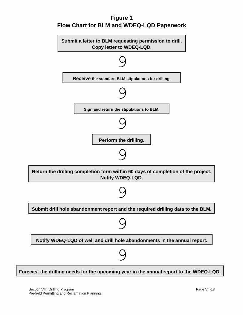
Section VII: Drilling Program Page VII-18Pre-field Permitting and Reclamation Planning
Figure 1Flow Chart for BLM and WDEQ-LQD Paperwork
Submit a letter to BLM requesting permission to drill.Copy letter to WDEQ-LQD.
9Receive the standard BLM stipulations for drilling.
9Sign and return the stipulations to BLM.
9Perform the drilling.
9Return the drilling completion form within 60 days of completion of the project.
Notify WDEQ-LQD.
9Submit drill hole abandonment report and the required drilling data to the BLM.
9Notify WDEQ-LQD of well and drill hole abandonments in the annual report.
9Forecast the drilling needs for the upcoming year in the annual report to the WDEQ-LQD.

Section VII: Drilling Program Page VII-19Pre-field Permitting and Reclamation Planning
Figure 2Figure 2Wyoming State Engineer's Office Paperwork and ActionsWyoming State Engineer's Office Paperwork and Actions
Submit Application for Permit to Appropriate Ground Water Submit Application for Permit to Appropriate Ground Water (UW-5) forms to the SEO.(UW-5) forms to the SEO.
9
Receive back copy of the UW-5 form and blank Completion Report (UW-6) with the permitnumber and the Notice of Commencement form. If drilling a production well, also receive
back a Proof of Appropriation and Beneficial Use (UW-8) form.
9Submit the "Notice of Commencement" after drilling is begun.
9Drill the well.
9Submit completed UW-6 form within 30 days of project completion.
9Submit completed UW-8 form by end of calendar year.
9Upon abandonment of the well, submit a letter informing SEO of proper
abandonment and referencing the permit number.

Section VII: Drilling Program Page VII-20
NOTES

Section VII: Drilling Program Page VII-21Contracting the Drilling Program
5. Contracting the Drilling Program
Section editor: D.G. Steward Subsection authors: Robert Cowan/D.G. Steward
~~~~~~~~~~~~~~~~~~~~~~~~~~~~~~~~~
Situation:
This subsection outlines the steps necessary for obtaining a contractor that will fill the needs of a
specific drilling program. Requirements and responsibilities for all contractors must be clearly
documented.
Special Considerations:
The contractor requirements for a drilling program should be specified in "Request for Quotation"
and "Scope of Work" documents. These needs will depend upon decisions already made regarding
drilling, logging, and sampling requirements. Exact responsibilities of each contractor should be
clearly specified. It is desirable to allow for some contractor flexibility in execution of the program,
while clearly stating requirements that must be met.
Description of Technique:
a. Prepare the Written Scope of Work
Include every aspect of the project as it pertains to the various contractors who may bid on
all or part of the project. Figure 1 (figure follows text) gives a checklist for preparing a
Scope of Work.
b. Identify Contractors
Prospective contractors bidding on the work should provide current statements of
qualifications, current licenses, references from previous clients, and a history of work
performed. The driller, the geologist, the logger, and the laboratory may be bid together as
a package or separately.

Section VII: Drilling Program Page VII-22Contracting the Drilling Program
(1) Driller
(a) Safety Record, MSHA Training
Investigate for any history of safety violations or accidents that may have
occurred, and determine if remedial steps were taken. Determine if the
contractor provides a safety training program for his employees, and
whether or not MSHA training has been completed if required.
(b) Suitable Equipment
Determine if the prospective contractor's equipment is appropriate to the job
and in good operating condition.
(c) Past Experience
If the prospective contractor has performed work for the mine previously,
information may be available from records or personnel about the quality of
work performance that can be expected.
(d) References
Obtain a list of references of previous clients from prospective contractors
about whom additional information is desired. Consult these clients
concerning past job performance.
(2) Geologist/Geotechnical Consultant
The geologist can be sub-contracted through the driller, requiring the driller to
coordinate all applicable activities, or vice-versa. The same information regarding
safety, equipment, experience, and references that are required for the driller
should also be obtained for the geologist/geotechnical consultant.
(3) Laboratories (Chemical/Geotechnical)
The same information regarding equipment, experience, and references that are
required for the driller should also be obtained for the laboratory. In addition to this,
it is necessary to ascertain if prospective laboratories have met standards of

Section VII: Drilling Program Page VII-23Contracting the Drilling Program
government or industry sponsored certifying agencies for the types of analysis
required.
Establish what timeframe is required to receive laboratory results and evaluate the
prospective lab's ability to meet requirements with respect to equipment, personnel,
and workload.
Laboratories must demonstrate that they can consistently achieve accurate
analytical results. In some cases it may be desirable to submit duplicate samples
or "spiked" samples to check lab performance. Selection of reputable, certified labs
and submission of duplicate samples to different labs can help minimize variability
of results caused by lab operations.
(4) Downhole Logger
The logger can be sub-contracted through the driller, requiring the driller to
coordinate all applicable activities. The same information regarding safety,
equipment, experience, and references that are required for the driller should also
be obtained for the downhole logger.
Check equipment calibration records to verify timely regular performance checks
of logging equipment. Identify the digital data capacity of the logger. In addition to
strip charts or other visual representations of data, it may be desirable to have
geophysical data provided in a digital form compatible with available computer
systems.
c. Contact Prospective Bidders
Contact prospective contractors to determine their availability to perform the work during
the proposed project timeframe.
d. Pre-bid Meeting
Meet with prospective contractors to discuss and clarify the Scope of Work prior to
accepting bids.

Section VII: Drilling Program Page VII-24Contracting the Drilling Program
e. Receive and Analyze Bids
Once bids have been received, prepare a master spreadsheet that allows a direct
comparison of both line item and overall bid costs. Discuss this comparison with
purchasing, accounting, and engineering personnel. Remember, the low bidder may not be
the best buy. Finally, select the contractor.
f. Schedule the Contractors
Prepare contract documents which establish a timeframe for beginning and completing
work and give contractors notice to proceed. If desired, establish the normal working hours
expected.

Section VII: Drilling Program Page VII-25Contracting the Drilling Program
Figure 1
Checklist for Preparing the Scope of Work for a Drilling Project.
1. Determine the purpose of the drilling.
2. Gather all pertinent documents that control the type of drilling proposed.
3. If geotechnical or other consultants are required to participate, obtain their input on specialrequirements for drilling, sampling, or analysis.
4. Define the sampling program for the project.
5. Determine the number, location, and depth of drill holes and list what types of drilling andsampling equipment are to be provided by the drilling contractor. Identify who is responsiblefor any equipment, such as probes, that may be lost down drill holes.
6. Note anticipated materials that may be encountered during drilling, and any atmospheric orsoil monitoring required.
7. Provide a map of the drill hole locations showing associated terrain features, access routes,any restricted areas, and pertinent geologic and hydrologic data that are available.
8. If appropriate, list the types of laboratory analysis required and the time frame in which theresults will be needed. The analysis of the samples may be bid separately from the drilling.
9. List the type of logs that need to be prepared during drilling, and who will prepare them.
10. If wells are to be developed, list the materials to be used and provide a drawing of thecompleted well.
11. Determine what reclamation and abandonment procedures are applicable to the project andlist specific materials to be used.
12. Determine who will provide well and/or reclamation materials.
13. Determine the time frame during which the project will be completed and any unusualworking schedules necessary to meet the deadlines which may be set.
14. Prepare a "Scope of Work" or "Request for Quotation" for each contractor to include all ofthe foregoing information.

Section VII: Drilling Program Page VII-26
NOTES

Section VII: Drilling Program Page VII-27Sample Storage
6. Sample Storage
Section editor: D.G. Steward Subsection authors: Robert Cowan/D.G. Steward
~~~~~~~~~~~~~~~~~~~~~~~~~~~~~~~~~
Situation:
Planning for the handling and storage of drilling samples will expedite these activities when field
work is actually being done. Storage facilities should be identified before they are needed.
Special Considerations:
Capacity, accessibility, and necessary climate control must be considered in the choosing of a
storage facility for drill samples.
Description of Technique:
a. Capacity and Accessibility
The sample storage facility must be large enough to allow samples to be easily identified
and sorted by hole number and depth interval. Use hole number, diameter, and depth to
estimate the total storage volume required. Loading and unloading of samples should be
as convenient as possible. Provide keys to the locked storage facility to authorized persons
only.
b. Temperature and Humidity
Ensure that climate control in the storage facility is adequate to preclude extremes of
temperature or humidity. Samples must not dry out, or lose volatile constituents during
storage.

Section VII: Drilling Program Page VII-28Sample Storage
c. Time Constraints
Transfer samples expeditiously to the analytical laboratory in accordance with good practice
for the types of analysis required. Determine how long it will be necessary to use the storage
location before samples are shipped.

Section VII: Drilling Program Page VII-29Field Activities
C. Field Work
1. Field Activities
Section editor: D.G. Steward Subsection authors: Robert Cowan/D.G. Steward
~~~~~~~~~~~~~~~~~~~~~~~~~~~~~~~~~
Situation:
This subsection is intended to outline the steps needed for actual field work required in a drilling
program, and to ensure that all elements of the program are addressed.
Special Considerations:
In any drilling program, supervision will be required regarding location, access, and drilling of holes,
as well as safety and environmental control considerations.
Description of Technique:
a. Locate and Identify Drill Holes
(1) Select Accessible Drilling Sites and Drillable Hole Locations
Locations of holes may have to be adjusted to avoid obstacles to accessibility, such
as swamps, ravines, steep slopes, and rock outcrops.
(2) Survey the Holes
Mark holes with a lath and flag or other suitable means. The following information
may be helpful if placed on the lath:
(a) Northing and easting or UTM coordinates.
(b) Elevation at the surface.
(c) The estimated depth to coal, and coal thickness (optional).
Section VII: Drilling Program Page VII-30Field Activities
(d) Type of hole (label the holes as monitoring, dewatering, exploration, etc. on
the marker).
(e) If GPS (Global Positioning System, based on satellite transmissions) is
available, this method may be used to locate drill holes.
b. Access the Drill Site
(1) Roadways
Special precautions may be necessary when permits or special permission have
been obtained. If special permission has been received to cross lands not controlled
by the mine, care must be taken to assure that all contractors are specifically
advised of routes to be followed and restrictions to be observed.
Use existing roads and trails whenever possible. Limit vehicular traffic to drill sites
to the minimum necessary. When wet conditions prevail, avoid areas where rutting
and vegetation damage will cause undue reclamation effort.
(2) Hours
Drilling operations are normally scheduled during daylight hours for safety. If night
drilling is anticipated, ensure that adequate lighting is provided.
(3) Restrictions
Drilling operations may involve movement of equipment in pit traffic areas, and, if
so, may have to be restricted to certain times or routes. Drilling may have to be
suspended and equipment moved during blasting operations.
c. Drill the Hole
(1) Special Sampling Considerations
Begin all drilling operations with clean equipment. Make sure any water, lubricants,
pipe dope, or similar items used during drilling do not contain materials that will be
analyzed in the samples, or that may interfere with analytical results. Obtain Material
Safety Data Sheets (MSDS) to verify the contents. For example, if samples are to

Section VII: Drilling Program Page VII-31Field Activities
be analyzed for molybdenum, then drill pipe grease containing molybdenum should
not be used while drilling and sampling.
(2) Environmental Considerations
(a) Safety (including monitoring for gases such as H2S and CH4)
Hydrogen sulfide and methane gases are routinely encountered when drilling
in coal and overburden. Other toxic or flammable vapors may be found,
especially when drilling in the vicinity of underground storage tanks. Have
monitoring devices for hazardous gases available to ascertain if explosive,
fire, or toxic exposure conditions exist. If toxic concentrations exceed the
threshold limit value or flammable gas concentrations exceed 10% of the
lower explosive limit in the work area, mitigating procedures must be taken
and personnel and equipment protected from hazards.
(b) Housekeeping
Require contractors to maintain a clean and orderly work place, and to
contain and dispose of waste materials in an approved manner. Unused
equipment, well supplies, and reclaiming materials should be stockpiled to
avoid damage or loss, and to present no hazard to drilling or mine
operations.
(c) Environmental Control
Excavate and backfill mud pits used to contain drilling fluid and cuttings in
accordance with the mine permit. Take any precautions that may be
necessary to protect people, livestock, and wildlife from open holes or other
hazards.
Require contractors to prevent uncontrolled release of excess drilling fluids
that may contaminate surface water or damage vegetation. Have the
contractor provide MSDS for all material to be used during the drilling
program.
d. Monitor Groundwater Levels

Section VII: Drilling Program Page VII-32Field Activities
This is always done for geotechnical drilling, and may be appropriate for other types of
holes. Instructions for monitoring are given in "Standard Method for Determining Subsurface
Liquid Levels in a Borehole or Monitoring Well (Observation Well)" (ASTM, 1994).
Section VII: Drilling Program Page VII-33Sample Collection
2. Sample Collection
Section editor: D.G. Steward Subsection authors: Robert Cowan/D.G. Steward
~~~~~~~~~~~~~~~~~~~~~~~~~~~~~~~~~
Situation:
Sample collection is an important part of the drilling program. This subsection is intended to cover
various aspects to be considered for all associated sampling. Sample requirements can be very
site specific; the information provided herein is intended for use as a guide only.
Special Considerations:
Methods used for collecting, bagging, and handling of samples will vary from mine to mine,
depending on permit and regulatory requirements, as well as the information that is to be collected.
Description of Technique:
a. Coal
There is usually no special cleaning required for coal sampling. Continuous coring through
coal, with at least 90% recovery, is usually required. The structural tops and bottoms of the
coal seams should coincide with sample interval starts and endings.
Sample collection can be made in a variety of ways. Composite coal samples can be taken
and submitted for analysis for each seam encountered. Samples can be taken at two-foot
intervals in the top and bottom six feet of coal, and at five to ten foot intervals between. The
company representative in charge of geology should be consulted on sample intervals.
Geophysical logs can be used to identify tops and bottoms of structures. If the parting is
identified, sampling is optional, but if sampling is required, separate bagging for the parting
is required.

Section VII: Drilling Program Page VII-34Sample Collection
b. Overburden
Holes are drilled and cored or chipped. The interval at which chip samples are collected is
set by the program administrator, and may depend upon bench height.
Subtract the estimated topsoil break and do not include as part of the overburden sample.
This may be as much as five feet. Cores can be bagged in two-foot intervals, then combined
for eight-foot intervals. When placing cores in boxes, orient the interval marking with the
actual orientation of the cores as they were removed from the ground. Select sampling
intervals consistent with the mine permit.
Selenium sampling may require special cleaning of samplers and equipment. Some
operators collect samples for selenium analysis in accordance with "Standard Operating
Procedures for the Sampling and Analysis of Selenium in Soil and Overburden/Spoil
Material" (Carroll, et al., 1994).
c. Backfill
Backfill monitoring and sampling requirements are usually specified in the mine permit. In
general, backfill sampling is required to demonstrate compliance with the mine permit.
d. Geotechnical
Normally, no special cleaning is required for geotechnical sampling. Types and locations of
samples to be taken are specified by the program administrator or a geotechnical
consultant. General requirements are outlined in the "Standard Guide for Investigating and
Sampling Soil and Rock" (ASTM, 1994).
Geotechnical samples are to be transported to laboratories in accordance with "Practices
for Preserving and Transporting Soil Samples" (ASTM, 1994).
e. Special Considerations
Begin all drilling operations with clean equipment. The type of sample dictates the procedure
required for cleaning equipment. For example, when sampling for selenium (if following
Carroll, et al., 1994), samplers, drill pipe, etc., must be washed with Alconox and rinsed
three times with distilled water between samples.

Section VII: Drilling Program Page VII-35Sample Collection
Make sure water, lubricants, pipe dope, and similar materials used during drilling operations
do not contain materials that will be analyzed in samples or that will interfere with analytical
results. Obtain MSDS to verify the contents. For example, if samples are to be analyzed for
molybdenum content, then drill pipe grease containing molybdenum should not be used
while drilling and sampling.
f. Handling
(1) Packaging
Core and chip samples should be placed in double plastic bags, to provide
additional resistance to damage and extra moisture protection. Seal both bags
separately with tape to assure no loss of moisture. 6-mil polyethylene bags are
adequate. All samples may then be placed in water resistant boxes for transport.
If core boxes are used, double bagging may not be necessary.
(2) Labelling
Color code or label clearly for coal, overburden, and backfill samples as necessary
to prevent confusion when handling samples. Mark the hole number and sample
interval on the outside of the bags, and also on a tag placed between the two
sample bags. Do not place sample tags inside the sample bag, as they will become
unreadable.
(3) Cataloging/inventory by Geologist or Driller
Any data collected that may eventually be computerized should be in a format that
reflects that eventuality. A copy of the lithologic log, which lists samples by number
and depth, may be included with samples submitted to the lab, and with a chain of
custody sheet, which should also accompany the samples.

Section VII: Drilling Program Page VII-36
NOTES
Section VII: Drilling Program Page VII-37Well Drilling
3. Well Drilling
Section editor: D.G. Steward Subsection authors: Robert Cowan/D.G. Steward
~~~~~~~~~~~~~~~~~~~~~~~~~~~~~~~~~
Situation:
This subsection outlines requirements that may be necessary in contracting the drilling of water
wells.
Special Considerations:
Physical requirements of each well will differ greatly. Specifications for casing size and depth,
placing of well screens, and any other requirements must be clearly designated to the contractor.
Overburden sampling when drilling dewatering wells may be desired to add to the overburden
quality or coal database.
Description of Technique:
Wells to be developed as production or monitoring wells do not need to have earthen samples
collected, although they may have. These wells must be cased with screen placed at the
water-bearing levels to be monitored or pumped.
All casing must be sealed to prevent contamination from surface or other undesired water sources.
Excess drill cuttings must be spread to one-quarter inch thickness, or disposed of in the pit or other
disposal area to prevent any chemical hazard. Wells can be protected from unauthorized access,
and are preferably maintained under lock and key.
In addition to the casing required to facilitate drilling and sampling, casing must be provided for the
development of monitoring or production wells. Specify the inside diameter of the casing, the
schedule of pipe to be used, the screen opening width, where the screen is to be placed, and the
type of any security device to be installed. Specify the particle size range of sand to be placed
around the well screen in wells. Wells are to be sealed from surface contamination or from
communication with aquifers that are not desired to be sampled or pumped. Identify any
preferences regarding brand names or sources of materials.

Section VII: Drilling Program Page VII-38
NOTES

Section VII: Drilling Program Page VII-39Logging
4. Logging
Section editor: D.G. Steward Subsection authors: Robert Cowan/D.G. Steward
~~~~~~~~~~~~~~~~~~~~~~~~~~~~~~~~~
Situation:
This subsection is intended to give a brief summary of the various types of downhole logging that
may be used in a drilling program.
Special Considerations:
The readouts from these logs may be used by one or more parties. There is often only one print-
out of each log, and it is difficult to copy. Obtain digital data in addition to hard copies when
possible. Information obtained from each log will differ, and can be compared with other logs for
confirmation of results.
Description of Technique:
a. Electrical Logs
Caliper, resistivity, and nuclear logs are the electrical logs normally obtained. The logs are
obtained by lowering a logging device down the hole. Data from electrical logging are
recorded digitally, and can be printed immediately in the field. The data are also usually
recorded as computer data files. To the extent drilling has been completed, logging should
also be completed by the end of each day.
(1) Caliper
The caliper log measures the hole diameter, and can be used in conjunction with
other logs to confirm readouts.

Section VII: Drilling Program Page VII-40Logging
(2) Resistivity
The resistivity log measures changes in the resistance of materials to electric
current, and is especially useful in identifying water levels, logging changes from
overburden to coal, and indicating fresh versus saline water.
(3) Nuclear
(a) Natural Gamma
Natural gamma radiation is emitted from downhole materials used to
delineate lithologies.
(b) Gamma (density)
Gamma radiation is attenuated in proportion to density of materials, and is
used to log changes in density in the profile.
(c) Neutron (porosity)
High speed neutrons are scattered by hydrogen-bearing materials such as
hydrocarbons or water, hence can be used to infer porosity in the profile.
b. Descriptive Logs
Descriptive logs include lithologic and core logs. These are prepared by the driller
or the geologist as material is removed from the hole. Drill logs should be received
and reviewed daily for completeness and accuracy.
(1) Lithologic Log
The lithologic log identifies depths and thicknesses of general geologic rock
types. This log is completed, for both chip and core drilling, by the driller or
geologist. Guidelines for lithologic logs are given in "Standard Guide for Field
Logging of Subsurface Explorations of Soil and Rock" (ASTM, 1994). Other
logging formats can be used as determined by the operator.

Section VII: Drilling Program Page VII-41Logging
(2) Core Log
The core log, which is generated by the geologist, is a description of specific
lithologic and environmental characteristics of the core as it is removed from
the hole.

Section VII: Drilling Program Page VII-42
NOTES

Section VII: Drilling Program Page VII-43Drill Hole Reclamation
D. Post-drilling Requirements
1. Drill Hole Reclamation
Section editor: D.G. Steward Subsection authors: Robert Cowan/D.G. Steward
~~~~~~~~~~~~~~~~~~~~~~~~~~~~~~~~~
Situation:
Proper reclamation and abandonment of all drill holes and disturbed areas are necessary as part
of the drilling program. Procedures must be planned for and outlined in the "Scope of Work". More
information on the Scope of Work document can be found in the subsection entitled "Contracting
the Drilling Program".
Special Considerations:
Permit requirements and appropriate regulations must be considered in planning proper
abandonment and reclamation of drill holes.
Description of Technique:
a. Documentation and Reporting
Documentation and reporting of all drilling activities are required. For more details
on reporting requirements, see the subsection entitled "Pre-field Permitting and
Reclamation Planning".
b. Reclamation Procedures
Reclamation and abandonment procedures are usually described in the mine
permit. Federal regulations regarding these procedures are listed in part c. or the
subsection entitled "Pre-field Permitting and Reclamation Planning". State
regulations may differ from state to state and should be investigated. Monitoring
wells must be reclaimed in accordance with appropriate regulations when the period
of monitoring is complete.

Section VII: Drilling Program Page VII-44Drill Hole Reclamation
Holes in the area to be mined in the next year should be made surface safe, but
need not be permanently reclaimed. Exploratory holes that will not be mined in the
next year must be permanently reclaimed. These holes are normally filled to the top
of coal with bentonite and above the coal with a mixture of bentonite and
overburden chips. If the top of the hole is within the projected topsoil stripping
depth, do not cap it. If the top of the hole is not within this depth, cap it with concrete
from two to seven feet. Cover the cap with topsoil after inspection.
Specify in the Scope of Work the reclamation practices that are to be followed, and
the estimated quantities of materials such as bentonite chips, concrete, or sand to
be used.
c. Disposal of Drill Cuttings
Drill cuttings, especially carbonaceous, should be replaced in the hole or hauled to
the coal mine prior to completing hole reclamation. Because monitoring and
production wells must remain open and free of debris, drill cuttings from these holes
should be spread around the hole to one-quarter inch thickness, or disposed of so
as to prevent any chemical hazard.

Section VII: Drilling Program Page VII-45Post-drilling Responsibilities
2. Post-drilling Responsibilities
Section editor: D.G. Steward Subsection authors: Robert Cowan/D.G. Steward
~~~~~~~~~~~~~~~~~~~~~~~~~~~~~~~~~
Situation:
This subsection outlines the post-field activities that accompany a drilling program. These activities
must be identified and assigned to responsible parties.
Special Considerations:
The responsibilities listed in this subsection can be efficiently carried out by more than one party.
For example, some of the work listed as the geologist's responsibility may be given to the
geotechnical consultant, at the discretion of the geologist or program administrator.
Description of Technique:
a. Geologist's Responsibilities
(1) Transporting Samples
Packaging and labelling of samples, and preparation of a list of samples collected,
are supervised in the field by the geologist or geotechnical consultant. Especially
during exploratory drilling and coring, a large number of heavy samples may be
obtained in a day's work. Specify in the Scope of Work who will provide a truck or
trailer of sufficient capacity, and labor for transporting samples to the storage facility
each day. More information on the Scope of Work document can be found in the
subsection entitled "Contracting the Drilling Program".
(2) Storing Samples
Store samples in the designated facility, but prevent excessively high temperatures.
Organize samples by drill hole in the storage facility. Use the inventory sheet

Section VII: Drilling Program Page VII-46Post-drilling Responsibilities
developed in the field for confirmation and tracking of samples. Overburden, coal,
and backfill samples may be separated for ease of handling.
(3) Completion of Activities Report
Require the geologist to complete a form summarizing all drilling data needed to
meet regulatory reporting requirements. Figure 1 gives a good example of a form
that may be used.
(4) Processing Samples
(a) Sample Handling
Submit samples for analysis to an appropriate lab promptly. Minimize delays
and environmental extremes in storage or transit. Geotechnical samples
must always be protected from excessive temperatures or drying out, as
their properties can be altered significantly by these processes. Ordinary air
temperatures are usually not detrimental to coal and overburden samples,
but direct sunlight may increase sample temperatures excessively.
Samples for chemical analysis are often sensitive to changes in temperature,
humidity, or contact with the air or other substances. Time restrictions may
apply, especially when analysis is to be performed for chemical properties
which vary significantly with biological activity in the sample or which exhibit
high volatility. Consult with the laboratory performing the analysis to
determine if special handling or field procedures are required to assure valid
results.
(b) Specifying Tests Required
Verify that all necessary testing has been included in the Scope of Work for
the laboratory, and communicate with laboratory representatives for
clarification.

FIGURE 1
Drilling Project Report Summarization
HOLE
TYPE
HOLE
NUMBER
LITHOLOGIC
LOG
ELECTRIC
LOG
DRILLER
S
LOG
COAL
ANALYSIS
OVERBURDE
N ANALYSIS
WATER
ANALYSIS
RECLAMATION
REPORT
COMPLETIO
N
REPORT
COMMENTS
BACKFILL
DEWATERING
EXPLORATION
GEOTECHNICAL
MONITORING
PRODUCTION

Section VII: Drilling Program Page VII-48Post-drilling Responsibilities
(c) Interpreting Results
Review the data and compare with previous data, noting significant changes
in values or variability. Note values which appear anomalous, and evaluate
possible causes.
b. Laboratory Responsibilities
In addition to hard copy, laboratories may also be able to provide data in digital format for
ease of assimilation into computer programs currently used for statistical analysis, plotting,
or drafting.
c. Program Administrator's Responsibilities
(1) Chain of Custody Forms
Review chain of custody forms that accompany samples to the lab, and document
changes in custody as samples change hands during the process of analysis or
transport. Look for completeness of the documentation and note discrepancies.
Maintain a file of these forms for reference should problems be encountered.
(2) Processing the Data
Analyze the data, reducing it to a form appropriate for the context in which it is
intended for use at the mine or by regulatory agencies.
(3) Presenting the Data in Usable Form
Computerize the data in a spreadsheet format such as Lotus. Data in this format
can be sorted by hole number, location, depth, date drilled, hole type, etc.
Disseminate this data to the users by appropriate means.

Section VII: Drilling Program Page VII-49Reporting, Inspection, and Recordkeeping Requirements
3. Reporting, Inspection, and Recordkeeping Requirements
Section editor: D.G. Steward Subsection authors: Robert Cowan/D.G. Steward
~~~~~~~~~~~~~~~~~~~~~~~~~~~~~~~~~
Situation:
Reporting and recordkeeping practices are vital to any successful drilling program. These needs
must be identified and assigned to responsible parties.
Special Considerations:
Some of the activities listed in this subsection may be efficiently carried out by more than one party
and may be assigned at the discretion of the program administrator.
Description of Technique:
a. Reporting
Reports, as described in the flowcharts in Figures 1 and 2 of the subsection entitled "Pre-
field Permitting and Reclamation Planning", must be completed and documented. Drilling
correspondence files should be developed and maintained by year and hole type to
document all reporting activities. Include all items given in this flow chart in the
documentation.
Documentation and reporting to the BLM should include geophysical and lithology reports,
coal quality reports, and completion/abandonment forms. State Land Quality annual reports
should include information on holes drilled, reclamation of drill holes, and bonding. In
Wyoming, remember to report to the State Engineer's Office any artesian well encountered
during drilling.
b. Inspection
All holes should be inspected by the program administrator after drilling, installation (in the
case of wells) and reclamation activities have been completed. A standard form may be

Section VII: Drilling Program Page VII-50Reporting, Inspection, and Recordkeeping Requirements
useful in documenting that the holes are left in an acceptable condition. Reclaimed holes
may be inspected by State or Federal regulatory authorities, at their discretion. It is best to
conduct your inspection before such an inspection is conducted by an outside party.
c. Recordkeeping
Maintenance of drilling files usually falls to the person responsible for maintaining the
geologic database. These files typically include computer files, hard copy files, and the all
important correspondence file.
(1) Computer Files
Maintaining computer data files is an important part of the drilling program. Sample
analysis data files should be kept together where they can be easily located.
Backup diskettes may also be kept on file.
(2) Hard Copies
Hard copies of drilling information can be filed numerically by hole number. Each
hard file should contain all information pertaining to that hole, including lithologic
and geophysical logs, depth to water, and laboratory sample analysis data. It may
be desirable to color code holes by type.
(3) Correspondence Notebook
Annual notebooks, subdivided by hole type, may be used to file copies of all
correspondence.

Section VII: Drilling Program Page VII-51References
E. References
American Society for Testing Materials. 1994. The 1994 Annual Book of ASTM Standards forConstruction, Volume 04.08, Standard Guide for Investigating and Sampling Soil and Rock.Library of Congress Catalog number 83-641658. pp. 1 - 7.
American Society for Testing Materials. 1994. The 1994 Annual Book of ASTM Standards forConstruction, Volume 04.08, Practices for Preserving and Transporting Soil Samples.Library of Congress Catalog number 83-641658. pp. 513 - 522.
American Society for Testing Materials. 1994. The 1994 Annual Book of ASTM Standards forConstruction, Volume 04.08, Standard Method for Determining Subsurface Liquid Levelsin a Borehole or Monitoring Well (Observation Well). Library of Congress Catalog number83-641658. pp. 872 - 877.
American Society for Testing Materials. 1994. The 1994 Annual Book of ASTM Standards forConstruction, Volume 04.09, Standard Guide for Field Logging of Subsurface Explorationsof Soil and Rock. Library of Congress Catalog number 83-641658. pp. 398 - 400.
Carroll, P.K., J.G. Luther, L.K. Spackman, D.G. Steward, G.F. Vance, and L.E. Vicklund. 1994.Standard Operating Procedures for the Sampling and Analysis of Selenium in Soil andOverburden/Spoil Material. University of Wyoming Agricultural Experiment Station, Laramie,Wyoming. 13 p.
Code of Federal Regulations. 1993. U.S. Government Printing Office, Superintendent ofDocuments, Mail Stop SSOP, Washington, D.C., 20402-9328. pp. 625 - 628.

Section VII: Drilling Program Page VII-52
NOTES