Handbook Drilling & Threading - Walter Tools
53
_ WALTER TITEX & WALTER PROTOTYP The perfect thread Product handbook Drilling & Threading
Transcript of Handbook Drilling & Threading - Walter Tools

_ WALTER TITEx & WALTER PRoToTyP
The perfect thread
Product handbook
Drilling & Threading
CONTENTS
2 Application examples
2 Longitudinal member machining 4 Gear machining
6 Product information
6 Walter Titex x·treme Plus drills 8 x·treme Plus range16 Walter Prototyp ECo-HT tap18 ECo-HT range
44 Everything you need to know about threads
44 Thread types in accordance with DIN 20246 Chart of tolerance positions48 Tapped hole types50 Chamfer forms of taps51 Chip sections of chamfer forms53 Chamfer clearance angle54 Thread clearance angle55 Blind hole tapping process58 Special thread cutting applications60 General notes on core holes62 Cooling and lubrication64 Gauging female threads66 Synchronous machining68 The thread forming method70 The thread milling method
72 Additional information
72 x·treme Plus cutting data74 x·treme Plus driving power75 ECo-HT tap cutting data76 TEC+CCS expert system78 Thread tapping core diameters80 Thread forming core diameters82 Troubleshooting: drilling88 Troubleshooting: threading90 Calculation Formulas92 Walter Titex CATexpress94 Walter Reconditioning Service

1Drilling & Threading
Walter has more to offer than just drilling and threading.
A demanding process
The production of female threads is one of the most demanding machining tasks in production engineering. Moreover, the threads are often not made until the end of the production chain, which re-quires a high level of process reliability. Yet, in mass production, manufactur-ers demand that threads be produced ever more speedily and economically, which necessitates continuous, ongoing development of processes and of drilling and threading tools. For female threads, there are essentially three production methods available: thread tapping, the proven method; thread forming, a chipless alternative; and thread milling, a method that offers a particularly high degree of reliability. Crucial to selecting the appropriate production method is having as broad a knowledge as possible of the advantages and disadvantages of each method as well as their practical limitations. Ultimately, the decision for or against a particular production method will have to be made under consideration of technical and economic factors.
The perfect core hole
Before the thread can be created, a core hole has to be drilled. The quality of the core hole has a considerable bearing on the cost efficiency and process reliability of the subsequent threading operation.
Our experts not only offer a compre-hensive range of drilling and reaming tools, they know exactly what is required to ensure results of consistently high quality and productivity. We offer inno-vative and dependable drilling solutions, whatever the diameter, from catalogue products to custom-made special tools.
The perfect thread
The better matched the drilling and threading tools are, the better the result will be. Our customers want measurably higher performance. Higher performance not only in terms of threading accuracy, tolerances and chip formation, but also in respect of avoiding bird nesting and oversizing. Walter will show you how tools can be used most efficiently. Only optimally matched, seamless solutions produce the perfect thread. With the combined expertise of Walter Titex and Walter Prototyp, we are able to deliver maximum efficiency in thread manufacturing.

2 3Drilling & Threading
Application example 1:
Longitudinal member machining
Walter Titex X·treme Plus Through hole drilling
Walter Prototyp Prototex ECO-HT Through hole threading
Benefits for you:85 % higher cutting speed –Tool life increased from 1,500 to 2,000 holes despite –increased cutting performanceMachining time reduced from 111 hours to 50 hours –61 hours of spare machine capacity –
Benefits for you:Double the cutting speed for the same tool life –Machining time reduced from 120 hours to 60 hours –60 hours of spare machine capacity –Double the productivity –
Cutting data:
Competitor X·treme Plusn [1/min] 2,046 3,797vc [m/min] 90 167f [mm] 0.28 0.34vf [mm/min] 573 1,291
Cutting data:
Competitor Prototex ECO-HTn [1/min] 298 597vc [m/min] 15 30vf [mm/min] 597 1,194
Tool: A3389DPLCutting material: Solid carbide / DPLDiameter: 14 mmDrilling depth: 25 mm
Workpiece material: QStE380TM (~S355MC)Tensile strength: 550 N/mm²Hole type: Through hole
Machine type: Machining centreAdaptor: Hydraulic expansion chuck
Tool: E2026302-M16Cutting material: HSS-E-PM / THLDiameter: M16Drilling depth: 25 mm
Workpiece material: QStE380TM (~S355MC)Tensile strength: 550 N/mm²Hole type: Through hole
Machine type: Machining centreAdaptor: Floating holder
Comparison: machining time / hole
0 s 1 s 2 s 3 s 4 s
Competitor
X·treme Plus
-55%
Comparison: machining time / thread
0 s 1 s 2 s 3 s 4 s
Competitor
Prototex ECO-HT
-50%

4 5Drilling & Threading
Application example 2:
Gear machining
Walter Titex X·treme Plus Through hole drilling
Walter Prototyp Prototex ECO-HT Through hole threading
Benefits for you:Cutting speed increased by 73 % –Tool life increased from 1,900 to 2,800 holes despite –increased cutting performanceMachining time reduced from 110 hours to 60 hours –50 hours of spare machine capacity –
Benefits for you:Cutting speed increased by 48 % –Tool life increased from 2,400 to 4,000 threads –Machining time reduced from 100 hours to 70 hours –30 hours of spare machine capacity –
Cutting data:
Competitor X·treme Plusn [1/min] 4,681 8,098vc [m/min] 100 173f [mm] 0.20 0.23vf [mm/min] 936 1,863
Cutting data:
Competitor Prototex ECO HTn [1/min] 995 1,472vc [m/min] 25 37vf [mm/min] 1,243 1,840
Tool: A3389DPLCutting material: Solid carbide / DPLDiameter: 6.8 mmDrilling depth: 25 mm
Workpiece material: 16MnCr5Tensile strength: 700 - 1,000 N/mm²Hole type: Through hole
Machine type: Machining centreAdaptor: Hydraulic expansion chuck
Tool: E2021342-M8Cutting material: HSS-E-PM / THLDiameter: M8Drilling depth: 25 mm
Workpiece material: 16MnCr5Tensile strength: 700 - 1,000 N/mm²Hole type: Through hole
Machine type: Machining centreAdaptor: Floating holder
Comparison: machining time / hole
0 s 1 s 2 s 3 s
Competitor
X·treme Plus
-45%
Comparison: machining time / thread
0 s 1 s 2 s 3 s
Competitor
Prototex ECO HT
-30%

6 7Drilling & Threading
Your ADvAnTAGes
Maximum productivity; at least –double that achievable using conventional tools = more productivity, lower production costsAlternative: Double the tool life –with conventional cutting data = e.g. fewer tool changesExcellent surface finish –High process reliability –Varied application possibilities –with regard to materials and application (e.g. MQL)Ensures spare machine capacity –
ProDuCT ADvAnTAGes
New type of multifunctional double coating “DPL – Double Performance Line” –(patent pending), consisting of a basic coating for protecting the tool and a special point coating. The combination with the point coating not only makes it possible to use at greater cutting speeds, it also ensures outstanding tool life with conventional cutting data.Unique grinding with optimised microgeometry for lower power consumption –and optimum surface quality.Solid carbide cutting material – micro grain K30F. –
Product information
Walter Titex X·treme Plus
With this tool Walter Titex is setting new standards in drilling with solid carbide tools. The drill incorporates a wealth of innovations – including the new patent pending multifunc-tional double coating (DPL) that has outstanding properties.With Walter Titex X·treme Plus you can increase the productivity in the series production of steel and cast iron components to a new level.
THe TooL
solid carbide high performance –drilling tool with internal coolant supplynew type of multifunctional double –coating DPL “Double Performance Line” (patent pending)drilling depth 5 x d (A3389DPL) and –3 x d (A3289DPL)diameter range from 3.0 to 20.0 mm –
THe APPLiCATion
for all steel and cast iron materials –as well as for stainless steels and non-ferrous metalsHPC machining –also suitable for dry machining with –internal MQL supply
X·TreMeThe new Walter Titex X·treme Series with a unique double coating: extremely innovative and extremely productive.
Cost savings and increases in productivity with the X·treme Plus
Costs
speed
- 50%
+ 200%
Special point geometry, 140° point angle
Internal coolant supply Optimised flute profile
Point coating with excellent wear properties and for high cutting speeds
Dimensions in accordance with DIN 6537 L and DIN 6537 K
Basic coating for outstanding chip removal
Standard shank DIN 6535 HA
X·treme Plus Type: A3289DPL, A3389DPL
Basic coating
Workpiece
Chip
Point coating
Carbide

8 9Drilling & Threading
Product information
X·treme Plus range – A3289DPL
Application: high performance twist drill for maximum productivity in steel, stainless steel, non-ferrous metals and cast iron materials. Extremely high feed and cutting speeds with superior process reliability and surface quality.
d1 mm m7
Ø inches/
no.
d2 mm h6
l1 mm l2 mm max.
l4 mm Order code A3289DPL...
4.650 6 66 24 36 -4.65
4.700 6 66 24 36 -4.7
4.763 3/16 IN 6 66 24 36 -3/16IN
4.800 6 66 28 36 -4.8
4.900 6 66 28 36 -4.9
5.000 6 66 28 36 -5
5.100 6 66 28 36 -5.1
5.159 13/64 IN 6 66 28 36 -13/64IN
5.200 6 66 28 36 -5.2
5.300 6 66 28 36 -5.3
5.400 6 66 28 36 -5.4
5.500 6 66 28 36 -5.5
5.550 6 66 28 36 -5.55
5.556 7/32 IN 6 66 28 36 -7/32IN
5.600 6 66 28 36 -5.6
5.700 6 66 28 36 -5.7
5.800 6 66 28 36 -5.8
5.900 6 66 28 36 -5.9
5.953 15/64 IN 6 66 28 36 -15/64IN
6.000 6 66 28 36 -6
6.100 8 79 34 36 -6.1
6.200 8 79 34 36 -6.2
6.300 8 79 34 36 -6.3
6.350 1/4 IN 8 79 34 36 -1/4IN
6.400 8 79 34 36 -6.4
6.500 8 79 34 36 -6.5
6.600 8 79 34 36 -6.6
6.700 8 79 34 36 -6.7
6.747 17/64 IN 8 79 34 36 -17/64IN
6.800 8 79 34 36 -6.8
6.900 8 79 34 36 -6.9
7.000 8 79 34 36 -7
7.100 8 79 41 36 -7.1
7.144 9/32 IN 8 79 41 36 -9/32IN
7.200 8 79 41 36 -7.2
7.300 8 79 41 36 -7.3
d1 mm m7
Ø inches/
no.
d2 mm h6
l1 mm l2 mm max.
l4 mm Order code A3289DPL...
3.000 6 62 20 36 -3
3.100 6 62 20 36 -3.1
3.175 1/8 IN 6 62 20 36 -1/8IN
3.200 6 62 20 36 -3.2
3.300 6 62 20 36 -3.3
3.400 6 62 20 36 -3.4
3.500 6 62 20 36 -3.5
3.572 9/64 IN 6 62 20 36 -9/64IN
3.600 6 62 20 36 -3.6
3.700 6 62 20 36 -3.7
3.800 6 66 24 36 -3.8
3.900 6 66 24 36 -3.9
3.969 5/32 IN 6 66 24 36 -5/32IN
4.000 6 66 24 36 -4
4.100 6 66 24 36 -4.1
4.200 6 66 24 36 -4.2
4.300 6 66 24 36 -4.3
4.366 11/64 IN 6 66 24 36 -11/64IN
4.400 6 66 24 36 -4.4
4.500 6 66 24 36 -4.5
4.600 6 66 24 36 -4.6
d1 d2
1ll 2 l 4

10 11Drilling & Threading
Product information
X·treme Plus range – A3289DPL
d1 mm m7
Ø inches/
no.
d2 mm h6
l1 mm l2 mm max.
l4 mm Order code A3289DPL...
7.400 8 79 41 36 7.4
7.500 8 79 41 36 7.5
7.541 19/64 IN 8 79 41 36 19/64IN
7.800 8 79 41 36 7.8
7.900 8 79 41 36 7.9
7.938 5/16 IN 8 79 41 36 5/16IN
8.000 8 79 41 36 8
8.100 10 89 47 40 8.1
8.200 10 89 47 40 8.2
8.300 10 89 47 40 8.3
8.334 21/64 IN 10 89 47 40 21/64IN
8.400 10 89 47 40 8.4
8.500 10 89 47 40 8.5
8.600 10 89 47 40 8.6
8.700 10 89 47 40 8.7
8.731 11/32 IN 10 89 47 40 11/32IN
8.800 10 89 47 40 8.8
9.000 10 89 47 40 9
9.128 23/64 IN 10 89 47 40 23/64IN
9.200 10 89 47 40 9.2
9.300 10 89 47 40 9.3
9.500 10 89 47 40 9.5
9.525 3/8 IN 10 89 47 40 3/8IN
9.600 10 89 47 40 9.6
9.700 10 89 47 40 9.7
9.800 10 89 47 40 9.8
9.922 25/64 IN 10 89 47 40 25/64IN
10.000 10 89 47 40 10
10.100 12 102 55 45 10.1
10.200 12 102 55 45 10.2
10.300 12 102 55 45 10.3
10.319 13/32 IN 12 102 55 45 13/32IN
10.400 12 102 55 45 10.4
10.500 12 102 55 45 10.5
10.716 27/64 IN 12 102 55 45 27/64IN
10.800 12 102 55 45 10.8
d1 mm m7
Ø inches/
no.
d2 mm h6
l1 mm l2 mm max.
l4 mm Order code A3289DPL...
11.000 12 102 55 45 -11
11.100 12 102 55 45 -11.1
11.113 7/16 IN 12 102 55 45 -7./1 IN
11.200 12 102 55 45 -11.2
11.500 12 102 55 45 -11.5
11.509 29/64 IN 12 102 55 45 -29/64IN
11.700 12 102 55 45 -11.7
11.800 12 102 55 45 -11.8
11.906 15/32 IN 12 102 55 45 -15/32IN
12.000 12 102 55 45 -12
12.100 14 107 60 45 -12.1
12.200 14 107 60 45 -12.2
12.300 14 107 60 45 -12.3
12.303 31/64 IN 14 107 60 45 -31/64IN
12.500 14 107 60 45 -12.5
12.600 14 107 60 45 -12.6
12.700 1/2 IN 14 107 60 45 -1/2IN
13.000 14 107 60 45 -13
13.300 14 107 60 45 -13.3
13.494 17/32 IN 14 107 60 45 -17/32IN
13.500 14 107 60 45 -13.5
14.000 14 107 60 45 -14
14.228 9/16 IN 16 115 65 48 -9/16IN
14.500 16 115 65 48 -14.5
15.000 16 115 65 48 -15
15.500 16 115 65 48 -15.5
15.875 5/8 IN 16 115 65 48 -5/8IN
16.000 16 115 65 48 -16
16.500 18 123 65 48 -16.5
17.000 18 123 65 48 -17
17.500 18 123 65 48 -17.5
18.000 18 123 65 48 -18
19.050 3/4 IN 20 131 79 50 -3/4IN
20.000 20 131 79 50 -20

12 13Drilling & Threading
Product information
X·treme Plus range – A3389DPL
d1 mm m7
Ø inches/
no.
d2 mm h6
l1 mm l2 mm max.
l4 mm Order code A3389DPL...
4.650 6 74 36 36 -4.65
4.700 6 74 36 36 -4.7
4.763 3/16 IN 6 82 44 36 -3/16IN
4.800 6 82 44 36 -4.8
4.900 6 82 44 36 -4.9
5.000 6 82 44 36 -5
5.100 6 82 44 36 -5.1
5.159 13/64 IN 6 82 44 36 -13/64IN
5.200 6 82 44 36 -5.2
5.300 6 82 44 36 -5.3
5.400 6 82 44 36 -5.4
5.500 6 82 44 36 -5.5
5.550 6 82 44 36 -5.55
5.556 7/32 IN 6 82 44 36 -7/32IN
5.600 6 82 44 36 -5.6
5.700 6 82 44 36 -5.7
5.800 6 82 44 36 -5.8
5.900 6 82 44 36 -5.9
5.953 15/64 IN 6 82 44 36 -15/64IN
6.000 6 82 44 36 -6
6.100 8 91 53 36 -6.1
6.200 8 91 53 36 -6.2
6.300 8 91 53 36 -6.3
6.350 1/4 IN 8 91 53 36 -1/4IN
6.400 8 91 53 36 -6.4
6.500 8 91 53 36 -6.5
6.600 8 91 53 36 -6.6
6.700 8 91 53 36 -6.7
6.747 17/64 IN 8 91 53 36 -17/64IN
6.800 8 91 53 36 -6.8
6.900 8 91 53 36 -6.9
7.000 8 91 53 36 -7
7.100 8 91 53 36 -7.1
7.144 9/32 IN 8 91 53 36 -9/32IN
7.200 8 91 53 36 -7.2
7.300 8 91 53 36 -7.3
d1 mm m7
Ø inches/
no.
d2 mm h6
l1 mm l2 mm max.
l4 mm Order code A3389DPL...
3.000 6 66 28 36 -3
3.100 6 66 28 36 -3.1
3.175 1/8 IN 6 66 28 36 -1/8IN
3.200 6 66 28 36 -3.2
3.300 6 66 28 36 -3.3
3.400 6 66 28 36 -3.4
3.500 6 66 28 36 -3.5
3.572 9/64 IN 6 66 28 36 -9/64IN
3.600 6 66 28 36 -3.6
3.700 6 66 28 36 -3.7
3.800 6 74 36 36 -3.8
3.900 6 74 36 36 -3.9
3.969 5/32 IN 6 74 36 36 -5/32IN
4.000 6 74 36 36 -4
4.100 6 74 36 36 -4.1
4.200 6 74 36 36 -4.2
4.300 6 74 36 36 -4.3
4.366 11/64 IN 6 74 36 36 -11/64IN
4.400 6 74 36 36 -4.4
4.500 6 74 36 36 -4.5
4.600 6 74 36 36 -4.6
Application: high performance twist drill for maximum productivity in steel, stainless steel, non-ferrous metals and cast iron materials. Extremely high feed and cutting speeds with superior process reliability and surface quality.
d1 d2
1ll 2 l 4

14 15Drilling & Threading
Product information
X·treme Plus range – A3389DPL
d1 mm m7
Ø inches/
no.
d2 mm h6
l1 mm l2 mm max.
l4 mm Order code A3389DPL...
11.000 12 118 71 45 -11
11.100 12 118 71 45 -11.1
11.113 7/16 IN 12 118 71 45 -7/16IN
11.200 12 118 71 45 -11.2
11.500 12 118 71 45 -11.5
11.509 29/64 IN 12 118 71 45 -29/64IN
11.700 12 118 71 45 -11.7
11.800 12 118 71 45 -11.8
11.906 15/32 IN 12 118 71 45 -15/32IN
12.000 12 118 71 45 -12
12.100 14 124 77 45 -12.1
12.200 14 124 77 45 -12.2
12.300 14 124 77 45 -12.3
12.303 31/64 IN 14 124 77 45 -31/64IN
12.500 14 124 77 45 -12.5
12.600 14 124 77 45 -12.6
12.700 1/2 IN 14 124 77 45 -1/2IN
13.000 14 124 77 45 -13
13.300 14 124 77 45 -13.3
13.494 17/32 IN 14 124 77 45 -17/32IN
13.500 14 124 77 45 -13.5
14.000 14 124 77 45 -14
14.288 9/16 IN 16 133 83 48 -9/16IN
14.500 16 133 83 48 -14.5
15.000 16 133 83 48 -15
15.500 16 133 83 48 -15.5
15.875 5/8 IN 16 133 83 48 -5/8IN
16.000 16 133 83 48 -16
16.500 18 143 93 48 -16.5
17.000 18 143 93 48 -17
17.500 18 143 93 48 -17.5
18.000 18 143 93 48 -18
19.050 3/4 IN 20 153 101 50 -3/4IN
20.000 20 153 101 50 -20
d1 mm m7
Ø inches/
no.
d2 mm h6
l1 mm l2 mm max.
l4 mm Order code A3389DPL...
7.400 8 91 53 36 -7.4
7.500 8 91 53 36 -7.5
7.541 19/64 IN 8 91 53 36 -19/64IN
7.800 8 91 53 36 -7.8
7.900 8 91 53 36 -7.9
7.938 5/16 IN 8 91 53 36 -5/16IN
8.000 8 91 53 36 -8
8.100 10 103 61 40 -8.1
8.200 10 103 61 40 -8.2
8.300 10 103 61 40 -8.3
8.334 21/64 IN 10 103 61 40 -21/64IN
8.400 10 103 61 40 -8.4
8.500 10 103 61 40 -8.5
8.600 10 103 61 40 -8.6
8.700 10 103 61 40 -8.7
8.731 11/32 IN 10 103 61 40 -11/32IN
8.800 10 103 61 40 -8.8
9.000 10 103 61 40 -9
9.128 23/64 IN 10 103 61 40 -23/64IN
9.200 10 103 61 40 -9.2
9.300 10 103 61 40 -9.3
9.500 10 103 61 40 -9.5
9.525 3/8 IN 10 103 61 40 -3/8IN
9.600 10 103 61 40 -9.6
9.700 10 103 61 40 -9.7
9.800 10 103 61 40 -9.8
9.922 25/64 IN 10 103 61 40 -25/64IN
10.000 10 103 61 40 -10
10.100 12 118 71 45 -10.1
10.200 12 118 71 45 -10.2
10.300 12 118 71 45 -10.3
10.319 13/32 IN 12 118 71 45 -13/32IN
10.400 12 118 71 45 -10.4
10.500 12 118 71 45 -10.5
10.716 27/64 IN 12 118 71 45 -27/64IN
10.800 12 118 71 45 -10.8

16 17Drilling & Threading
Your ADvAnTAGes
Secure chip control ensures –excellent process reliability even with relatively deep blind hole or through-hole threadsReduction in tool diversity, since –it can be used universally in a wide range of materialsFewer tool changes and optimum –machine output resulting from high cutting speeds and long tool lifeReduction in cooling lubricant –costs thanks to compatibility with dry or MQL machining in steel, cast iron and aluminium alloys
Product information
Walter Prototyp eCo-HT tap
THe TooL
Universal high-performance HSS-E- –PM tap for use in long- and short-chipping materials with a tensile strength of up to approximately 1,300 N/mm² on conventional machines or machine tools with synchronous spindleTHL hard material coating and –additional surface treatment for outstanding tool life with no cold weldingVersions with radial coolant outlet –available as standard tool specifically for use with minimum quantity lubrication (MQL)
Prototex eCo-HT –through-hole thread: · Special form B spiral point guaran-
tees excellent process reliability
Paradur eCo-HT blind hole thread: – · R45 helix angle, long flutes and
special flute geometry for optimum chip formation and good chip removal even in deep threads
· Thread almost to base of bore due to variant with short chamfer form E
· Reduced risk of spalling thanks to tapered thread runout
· Version available with axial internal cooling for optimum chip removal
THe APPLiCATion
Blind-hole or through-hole threads –down to 3 x dECO-HT taps are suitable for use with –a broad range of materials:
· Long-chipping materials having moderate to high tensile strength
· Short-chipping materials · Abrasive materials with a tendency
to weld · Construction steel or high tensile
steel (350 – 1,300 N/mm²) · Stainless steel · Nodular cast and malleable
cast iron · Long-chipping copper and
aluminium alloys
Straight fluted with spiral point form B
THL hard material coating
R45 helix angle with chamfer form C or E
Tapered thread runout
Long flutes and special flute geometry
Special surface treatment Special surface treatment
THL hard material coating
HSS-E-PM HSS-E-PM
Radial internal coolingAxial or radialinternal cooling
Prototex eCo-HT Type: E2021342 Paradur eCo-HT Type: E2051312

18 19Drilling & Threading
Product information
Prototex eCo-HT range
1.2-6.1 2.1-4 3.1-5 6.1-3 7.2-3.2 1.2-6.1 2.1-4 3.1-5 6.1-3 7.2-3.2
HSS-EPM B= 3,5 - 5 RH
MDIN13
MDIN13
Din 371 6HX
d1
mm
P
mm
l1 js16 mm
l2
mm
l3 ±1 mm
d2 h9 mm
a h12 mm
l4
mm
N Code E2021302
THL
M 2 0.4 45 6 9 2.8 2.1 5 3 -M2
M 2.5 0.45 50 8 12.5 2.8 2.1 5 3 -M2.5
M 3 0.5 56 9 18 3.5 2.7 6 3 -M3
M 4 0.7 63 12 21 4.5 3.4 6 3 -M4
M 5 0.8 70 13 25 6 4.9 8 3 -M5
M 6 1 80 15 30 6 4.9 8 3 -M6
M 8 1.25 90 18 35 8 6.2 9 3 -M8
M 10 1.5 100 20 39 10 8 11 3 -M10
Din 376 6HX
d1
mm
P
mm
l1 js16 mm
l2
mm
l3 ±1 mm
d2 h9 mm
a h12 mm
l4
mm
N Code E2026302
THL
M 12 1.75 110 23 - 9 7 10 4 -M12
M 14 2 110 25 - 11 9 12 4 -M14
M 16 2 110 25 - 12 9 12 4 -M16
M 18 2.5 125 30 - 14 11 14 4 -M18
M 20 2.5 140 30 - 16 12 15 4 -M20
M 24 3 160 36 - 18 14.5 17 4 -M24
M 27 3 160 36 - 20 16 19 4 -M27
M 30 3.5 180 42 - 22 18 21 4 -M30
Din 371 6GX
d1
mm
P
mm
l1 js16 mm
l2
mm
l3 ±1 mm
d2 h9 mm
a h12 mm
l4
mm
N Code E2023302
THL
M 2 0.4 45 6 9 2.8 2.1 5 3 -M2
M 2.5 0.45 50 8 12.5 2.8 2.1 5 3 -M2,5
M 3 0.5 56 9 18 3.5 2.7 6 3 -M3
M 4 0.7 63 12 21 4.5 3.4 6 3 -M4
M 5 0.8 70 13 25 6 4.9 8 3 -M5
M 6 1 80 15 30 6 4.9 8 3 -M6
M 8 1.25 90 18 35 8 6.2 9 3 -M8
M 10 1.5 100 20 39 10 8 11 3 -M10
Din 376 6GX
d1
mm
P
mm
l1 js16 mm
l2
mm
l3 ±1 mm
d2 h9 mm
a h12 mm
l4
mm
N Code E2028302
THL
M 12 1.75 110 23 - 9 7 10 4 -M12
M 14 2 110 25 - 11 9 12 4 -M14
M 16 2 110 25 - 12 9 12 4 -M16
HSS-EPM B= 3,5 - 5 RH
N/mm2
1350/42 HRC
500
N/mm2
1350/42 HRC
500
3,5 x d13,5 x d1
DryDry

20 21Drilling & Threading
Product information
Prototex eCo-HT range
1.2-6.1 2.1-4 3.1-5 6.1-3 7.2-3.2 1.2-6.1 2.1-4 3.1-5 6.1-3 7.2-3.2
Din 371 6HX
d1
mm
P
mm
l1 js16 mm
l2
mm
l3 ±1 mm
d2 h9 mm
a h12 mm
l4
mm
N Code E2021342
THL
M 6 1 80 15 30 6 4.9 8 3 -M6
M 8 1.25 90 18 35 8 6.2 9 3 -M8
M 10 1.5 100 20 39 10 8 11 3 -M10
Din 376 6HX
d1
mm
P
mm
l1 js16 mm
l2
mm
l3 ±1 mm
d2 h9 mm
a h12 mm
l4
mm
N Code E2026342
THL
M 12 1.75 110 23 - 9 7 10 4 -M12
M 16 2 110 25 - 12 9 12 4 -M16
Din 371 6HX
d1
mm
P
mm
l1 js16 mm
l2
mm
l3 ±1 mm
d2 h9 mm
a h12 mm
l4
mm
N Code E2021382
THL
M 3 LH 0.5 56 9 18 3.5 2.7 6 3 -M3
M 4 LH 0.7 63 12 21 4.5 3.4 6 3 -M4
M 5 LH 0.8 70 13 25 6 4.9 8 3 -M5
M 6 LH 1 80 15 30 6 4.9 8 3 -M6
M 8 LH 1.25 90 18 35 8 6.2 9 3 -M8
M 10 LH 1.5 100 20 39 10 8 11 3 -M10
Din 376 6HX
d1
mm
P
mm
l1 js16 mm
l2
mm
l3 ±1 mm
d2 h9 mm
a h12 mm
l4
mm
N Code E2026382
THL
M 12 LH 1.75 110 23 - 9 7 10 4 -M12
M 16 LH 2 110 25 - 12 9 12 4 -M16
M 20 LH 2.5 140 30 - 16 12 15 4 -M20
HSS-EPM B= 3,5 - 5 RH
N/mm2
1350/42 HRC
500
3,5 x d1
Dry
HSS-EPM B= 3,5 - 5 LH
N/mm2
1350/42 HRC
500
3,5 x d1
Dry
MDIN13
MDIN13

22 23Drilling & Threading
Product information
Paradur eCo-HT range
1.2-6.1 2.1-4 3.1-5 5.2 6.1-3 7.2-3.21.2-6.1 2.1-4 3.1-5 5.2 6.1-3 7.2-3.2
~ Din 371 6HX
d1
mm
P
mm
l1 js16 mm
l2
mm
l3 ±1 mm
d2 h9 mm
a h12 mm
l4
mm
N Code E2051302
THL
M 2 0.4 45 4 7.6 2.8 2.1 5 3 -M2
M 2.5 0.45 50 4 9.3 2.8 2.1 5 3 -M2,5
M 3 0.5 56 6 11 3.5 2.7 6 3 -M3
M 4 0.7 63 7 14.8 4.5 3.4 6 3 -M4
M 5 0.8 70 8 20.7 6 4.9 8 3 -M5
M 6 1 80 10 25 6 4.9 8 3 -M6
M 8 1.25 90 12 35 8 6.2 9 3 -M8
M 10 1.5 100 15 39 10 8 11 3 -M10
Din 376 6HX
d1
mm
P
mm
l1 js16 mm
l2
mm
l3 ±1 mm
d2 h9 mm
a h12 mm
l4
mm
N Code E2056302
THL
M 12 1.75 110 16 - 9 7 10 4 -M12
M 14 2 110 20 - 11 9 12 4 -M14
M 16 2 110 20 - 12 9 12 4 -M16
M 18 2.5 125 25 - 14 11 14 4 -M18
M 20 2.5 140 25 - 16 12 15 4 -M20
M 24 3 160 30 - 18 14.5 17 4 -M24
M 27 3 160 30 - 20 16 19 5 -M27
M 30 3.5 180 35 - 22 18 21 5 -M30
M 36 4 200 40 - 28 22 25 5 -M36
M 42 4.5 200 45 - 32 24 27 5 -M42
~Din 371 6GX
d1
mm
P
mm
l1 js16 mm
l2
mm
l3 ±1 mm
d2 h9 mm
a h12 mm
l4
mm
N Code e2053302
THL
M 2 0.4 45 4 7.6 2.8 2.1 5 3 -M2
M 2.5 0.45 50 4 9.3 2.8 2.1 5 3 -M2,5
M3 0.5 56 6 11 3.5 2.7 6 3 -M3
M 4 0.7 63 7 14.8 4.5 3.4 6 3 -M4
M 5 0.8 70 8 20.7 6 4.9 8 3 -M5
M 6 1 80 10 25 6 4.9 8 3 -M6
M 8 1.25 90 12 35 8 6.2 9 3 -M8
M 10 1.5 100 15 39 10 8 11 3 -M10
Din 376 6GX
d1
mm
P
mm
l1 js16 mm
l2
mm
l3 ±1 mm
d2 h9 mm
a h12 mm
l4
mm
N Code E2058302
THL
M 12 1.75 110 16 - 9 7 10 4 -M12
M 14 2 110 20 - 11 9 12 4 -M14
M 16 2 110 20 - 12 9 12 4 -M16
d1 d2
a
l2 l4l3
l1
HSS-EPM C = 2-3
R45RH
N/mm2
1250/38 HRC
500
3 x d1
Dry
HSS-EPM C = 2-3
R45RH
N/mm2
1250/38 HRC
500
3 x d1
Dry
d1 d2
a
l2 l4l3
l1
MDIN13
MDIN13

24 25Drilling & Threading
Product information
Paradur eCo-HT range
1.2-6.1 2.1-4 3.1-5 6.1-3 7.2-3.2 1.2-6.1 2.1-4 3.1-5 6.1-3 7.2-3.2
~ Din 371 6HX
d1
mm
P
mm
l1 js16 mm
l2
mm
l3 ±1 mm
d2 h9 mm
a h12 mm
l4
mm
N Code E2051802
THL
M 4 0.7 63 7 14.8 4.5 3.4 6 3 -M4
M 5 0.8 70 8 20.7 6 4.9 8 3 -M5
M 6 1 80 10 25 6 4.9 8 3 -M6
M 8 1.25 90 12 35 8 6.2 9 4 -M8
M 10 1.5 100 15 39 10 8 11 4 -M10
Din 376 6HX
d1
mm
P
mm
l1 js16 mm
l2
mm
l3 ±1 mm
d2 h9 mm
a h12 mm
l4
mm
N Code E2056802
THL
M 12 1.75 110 16 - 9 7 10 4 -M12
M 16 2 110 20 - 12 9 12 5 -M16
M 20 2.5 140 25 - 16 12 15 5 -M20
M 24 3 160 30 - 18 14.5 17 5 -M24
~Din 371 6HX
d1
mm
P
mm
l1 js16 mm
l2
mm
l3 ±1 mm
d2 h9 mm
a h12 mm
l4
mm
N Code E2051312
THL
M 4 0.7 63 7 14.8 4.5 3.4 6 3 -M4
M 5 0.8 70 8 20.7 6 4.9 8 3 -M5
M 6 1 80 10 25 6 4.9 8 3 -M6
M 8 1.25 90 12 35 8 6.2 9 3 -M8
M 10 1.5 100 15 39 10 8 11 3 -M10
Din 376 6HX
d1
mm
P
mm
l1 js16 mm
l2
mm
l3 ±1 mm
d2 h9 mm
a h12 mm
l4
mm
N Code E2056312
THL
M 12 1.75 110 16 - 9 7 10 4 -M12
M 16 2 110 20 - 12 9 12 4 -M16
M 20 2.5 140 25 - 16 12 15 4 -M20
M 24 3 160 30 - 18 14.5 17 4 -M24
d1 d2
a
l2 l4l3
l1
HSS-EPM E=1,5-2
R45RH
N/mm2
1250/38 HRC
500
3 x d1
Dry
HSS-EPM C = 2-3
R45RH
N/mm2
1250/38 HRC
500
3 x d1
MDIN13
MDIN13

26 27Drilling & Threading
Product information
Paradur eCo-HT range
1.2-6.1 2.1-4 3.1-5 6.1-3 7.2-3.2 1.2-6.1 2.1-4 3.1-5 6.1-3 7.2-3.2
Din 371 6HX
d1
mm
P
mm
l1 js16 mm
l2
mm
l3 ±1 mm
d2 h9 mm
a h12 mm
l4
mm
N Code E2051342
THL
M 8 1.25 90 12 35 8 6.2 9 3 -M8
M 10 1.5 100 15 39 10 8 11 3 -M10
Din 376 6HX
d1
mm
P
mm
l1 js16 mm
l2
mm
l3 ±1 mm
d2 h9 mm
a h12 mm
l4
mm
N Code E2056342
THL
M 12 1.75 110 16 - 9 7 10 4 -M12
M 16 2 110 20 - 12 9 12 4 -M16
~ Din 371 6HX
d1
mm
P
mm
l1 js16 mm
l2
mm
l3 ±1 mm
d2 h9 mm
a h12 mm
l4
mm
N Code E2051382
THL
M 3 LH 0.5 56 6 11 3.5 2.7 6 3 -M3
M 4 LH 0.7 63 7 14.8 4.5 3.4 6 3 -M4
M 5 LH 0.8 70 8 20.7 6 4.9 8 3 -M5
M 6 LH 1 80 10 25 6 4.9 8 3 -M6
M 8 LH 1.25 90 12 35 8 6.2 9 3 -M8
M 10 LH 1.5 100 15 39 10 8 11 3 -M10
Din 376 6HX
d1
mm
P
mm
l1 js16 mm
l2
mm
l3 ±1 mm
d2 h9 mm
a h12 mm
l4
mm
N Code E2056382
THL
M 12 LH 1.75 110 16 - 9 7 10 4 -M12
M 14 LH 2 110 20 - 11 9 12 4 -M14
M 16 LH 2 110 20 - 12 9 12 4 -M16
M 18 LH 2.5 125 25 - 14 11 14 4 -M18
M 20 LH 2.5 140 25 - 16 12 15 4 -M20
HSS-EPM C = 2-3
R45RH
N/mm2
1250/38 HRC
500
3 x d1
Dry
HSS-EPM C = 2-3
L45LH
N/mm2
1250/38 HRC
500
3 x d1
Dry
MDIN13
MDIN13

28 29Drilling & Threading
Product information
Prototex eCo-HT range
1.2-6.1 2.1-4 3.1-5 6.1-3 7.2-3.2 1.2-6.1 2.1-4 3.1-5 6.1-3 7.2-3.2
Din 374 6HX
d1
mm
P
mm
l1 js16 mm
l2
mm
d2 h9mm
a h12 mm
l4
mm
N Code E2126302
THL
M6 0.75 80 15 4.5 3.4 6 3 -M6X0.75
M8 1 90 18 6 4.9 8 3 -M8X1
M10 1 90 20 7 5.5 8 3 -M10X1
M12 1 100 21 9 7 10 4 -M12X1
M10 1.25 100 20 7 5.5 8 3 -M10X1.25
M12 1.25 100 21 9 7 10 4 -M12X1.25
M12 1.5 100 21 9 7 10 4 -M12X1.5
M14 1.5 100 21 11 9 12 4 -M14X1.5
M16 1.5 100 21 12 9 12 4 -M16X1.5
M18 1.5 100 24 14 11 14 4 -M18X1.5
M20 1.5 125 24 16 12 15 4 -M20X1.5
M22 1.5 125 24 18 14.5 17 4 -M22X1.5
Din 374 6HX
d1
mm
P
mm
l1 js16 mm
l2
mm
d2 h9 mm
a h12 mm
l4
mm
N Code E2126342
THL
M8 1 90 18 6 4.9 8 3 -M8X1
M10 1 90 20 7 5.5 8 3 -M10X1
M12 1 100 21 9 7 10 4 -M12X1
M10 1.25 100 20 7 5.5 8 3 -M10X1.25
M12 1.25 100 21 9 7 10 4 -M12X1.25
M12 1.5 100 21 9 7 10 4 -M12X1.5
M14 1.5 100 21 11 9 12 4 -M14X1.5
M16 1.5 100 21 12 9 12 4 -M16X1.5
M18 1.5 110 24 14 11 14 4 -M18X1.5
M20 1.5 125 24 16 12 15 4 -M20X1.5
HSS-EPM B= 3,5 - 5 RH
N/mm2
1350/42 HRC
500
3,5 x d1
Dry
HSS-EPM B= 3,5 - 5 RH
N/mm2
1350/42 HRC
500
3,5 x d1
Dry
MFDIN13
MFDIN13

30 31Drilling & Threading
Product information
Paradur eCo-HT range
1.2-6.1 2.1-4 3.1-5 6.1-3 7.2-3.21.2-6.1 2.1-4 3.1-5 5.2 6.1-3 7.2-3.2
Din 374 6HX
d1
mm
P
mm
l1 js16 mm
l2
mm
d2 h9 mm
a h12 mm
l4
mm
N Code E2156302
THL
M6 0.75 80 10 4.5 3.4 6 3 -M6X0.75
M8 1 90 13 6 4.9 8 3 -M8X1
M10 1 90 12 7 5.5 8 3 -M10X1
M12 1 100 13 9 7 10 4 -M12X1
M10 1.25 100 15 7 5.5 8 3 -M10X1.25
M12 1.25 100 13 9 7 10 4 -M12X1.25
M12 1.5 100 13 9 7 10 4 -M12X1.5
M14 1.5 100 15 11 9 12 4 -M14X1.5
M16 1.5 100 15 12 9 12 4 -M16X1.5
M18 1.5 100 17 14 11 14 4 -M18X1.5
M20 1.5 125 17 16 12 15 4 -M20X1.5
M22 1.5 125 18 18 14.5 17 5 -M22X1.5
Din 374 6HX
d1
mm
P
mm
l1 js16 mm
l2
mm
d2 h9 mm
a h12 mm
l4
mm
N Code E2156312
THL
M8 1 90 13 6 4.9 8 3 -M8X1
M10 1 90 12 7 5.5 8 3 -M10X1
M12 1 100 13 9 7 10 4 -M12X1
M10 1.25 100 15 7 5.5 8 3 -M10X1.25
M12 1.25 100 13 9 7 10 4 -M12X1.25
M12 1.5 100 13 9 7 10 4 -M12X1.5
M14 1.5 100 15 11 9 12 4 -M14X1.5
M16 1.5 100 15 12 9 12 4 -M16X1.5
M18 1.5 110 17 14 11 14 4 -M18X1.5
M20 1.5 125 17 16 12 15 4 -M20X1.5
d1 d2
a
l2 l4l1
HSS-EPM C = 2-3
R45RH
N/mm2
1250/38 HRC
500
N/mm2
1250/38 HRC
500
3 x d1 3 x d1
Dry Dry
HSS-EPM C = 2-3
R45RH
MFDIN13
MFDIN13

32 33Drilling & Threading
Product information
Paradur eCo-HT range
1.2-6.1 2.1-4 3.1-5 6.1-3 7.2-3.2
Din 374 6HX
d1
mm
P
mm
l1 js16 mm
l2
mm
d2 h9 mm
a h12 mm
l4
mm
N Code E2156802
THL
M8 1 90 13 6 4.9 8 4 M8X1
M10 1 90 12 7 5.5 8 5 M10X1
M12 1.5 100 13 9 7 10 5 M12X1.5
M14 1.5 100 15 11 9 12 5 M14X1.5
d1 d2
a
l2 l4l1
HSS-EPM E=1,5-2
R45RH
N/mm2
1250/38 HRC
500
3 x d1
Dry
MFDIN13

34 35Drilling & Threading
Product information
Prototex eCo-HT range
1.2-6.1 2.1-4 3.1-5 6.1-3 7.2-3.2
Din 2184-1 2B
d1-P Nom
d1
mm
l1 js16 mm
l2
mm
l3 ±1 mm
d2 h9 mm
a h12 mm
l4
mm
N Code E2221302
THL
No. 2-56 2.184 45 7 12 2.8 2.1 5 3 -UNC2
No. 4-40 2.845 56 9 18 3.5 2.7 6 3 -UNC4
No. 6-32 3.505 56 11 20 4 3 6 3 -UNC6
No. 8-32 4.166 63 12 21 4.5 3.4 6 3 -UNC8
No. 10-24 4.826 70 13 25 6 4.9 8 3 -UNC10
1/4-20 6.35 80 15 30 7 5.5 8 3 -UNC1/4
Din 2184-1 2B
d1-P Nom
d1
mm
l1 js16 mm
l2
mm
l3 ±1 mm
d2 h9 mm
a h12 mm
l4
mm
N Code E2226302
THL
5/16-18 7.938 90 18 - 6 4.9 8 3 -UNC5/16
3/8-16 9.525 100 20 - 7 5.5 8 3 -UNC3/8
1/2-13 12.7 110 23 - 9 7 10 4 -UNC1/2
5/8-11 15.875 110 25 - 12 9 12 4 -UNC5/8
HSS-EPM B= 3,5 - 5 RH
N/mm2
1350/42 HRC
500
3,5 x d1
Dry
UNCASME B1.1
1.2-6.1 2.1-4 3.1-5 6.1-3 7.2-3.2
Din 2184-1 2B
d1-P Nom
d1
mm
l1 js16 mm
l2
mm
l3 ±1 mm
d2 h9 mm
a h12 mm
l4
mm
N Code E2221342
THL
1/4-20 6.35 80 15 30 7 5.5 8 3 -UNC1/4
Din 2184-1 2B
d1-P Nom
d1
mm
l1 js16 mm
l2
mm
l3 ±1 mm
d2 h9 mm
a h12 mm
l4
mm
N Code E2226342
THL
5/16-18 7.938 90 18 - 6 4.9 8 3 -UNC5/16
3/8-16 9.525 100 20 - 7 5.5 8 3 -UNC3/8
1/2-13 12.7 110 23 - 9 7 10 4 -UNC1/2
5/8-11 15.875 110 25 - 12 9 12 4 -UNC5/8
HSS-EPM B= 3,5 - 5 RH
N/mm2
1350/42 HRC
500
3,5 x d1
Dry
UNCASME B1.1

36 37Drilling & Threading
Product information
Paradur eCo-HT range
1.2-6.1 2.1-4 3.1-5 5.2 6.1-3 7.2-3.2
~Din 2184-1 2B
d1-P Nom
d1
mm
l1 js16 mm
l2
mm
l3 ±1 mm
d2 h9 mm
a h12 mm
l4
mm
N Code E2251302
THL
No. 2-56 2.184 45 4 8.4 2.8 2.1 5 3 -UNC2
No. 4-40 2.845 56 6 11 3.5 2.7 6 3 -UNC4
No. 6-32 3.505 56 6.5 13.7 4 3 6 3 -UNC6
No. 8-32 4.166 63 7 17.8 4.5 3.4 6 3 -UNC8
No. 10-24 4.826 70 8 20.7 6 4.9 8 3 -UNC10
1/4-20 6.35 80 10 27.3 7 5.5 8 3 -UNC1/4
Din 2184-1 2B
d1-P Nom
d1
mm
l1 js16 mm
l2
mm
l3 ±1 mm
d2 h9 mm
a h12 mm
l4
mm
N Code E2256302
THL
5/16-18 7.938 90 13 - 6 4.9 8 3 -UNC5/16
3/8-16 9.525 100 15 - 7 5.5 8 3 -UNC3/8
1/2-13 12.7 110 18 - 9 7 10 4 -UNC1/2
5/8-11 15.875 110 20 - 12 9 12 4 -UNC5/8
d1 d2
a
l2 l4l3
l1
HSS-EPM C = 2-3
R45RH
N/mm2
1250/38 HRC
500
3 x d1
Dry
UNCASME B1.1
1.2-6.1 2.1-4 3.1-5 6.1-3 7.2-3.2
~Din 2184-1 2B
d1-P Nom
d1
mm
l1 js16 mm
l2
mm
l3 ±1 mm
d2 h9 mm
a h12 mm
l4
mm
N Code E2251312
THL
1/4-20 6.35 80 10 27.3 7 5.5 8 3 -UNC1/4
Din 2184-1 2B
d1-P Nom
d1
mm
l1 js16 mm
l2
mm
l3 ±1 mm
d2 h9 mm
a h12 mm
l4
mm
N Code E2256312
THL
5/16-18 7.938 90 13 - 6 4.9 8 3 -UNC5/16
3/8-16 9.525 100 15 - 7 5.5 8 3 -UNC3/8
1/2-13 12.7 110 18 - 9 7 10 4 -UNC1/2
5/8-11 15.875 110 20 - 12 9 12 4 -UNC5/8
3/4-10 19.05 125 25 - 14 11 14 4 -UNC3/4
HSS-EPM C = 2-3
R45RH
N/mm2
1250/38 HRC
500
3 x d1
Dry
UNCASME B1.1

38 39Drilling & Threading
Product information
Prototex eCo-HT range
1.2-6.1 2.1-4 3.1-5 6.1-3 7.2-3.2
Din 2184-1 2B
d1-P Nom
d1
mm
l1 js16 mm
l2
mm
l3 ±1 mm
d2 h9 mm
a h12 mm
l4
mm
N Code E2321302
THL
No. 4-48 2.845 56 9 18 3.5 2.7 6 3 -UNF4
No. 6-40 3.505 56 11 20 4 3 6 3 -UNF6
No. 8-36 4.166 63 12 21 4.5 3.4 6 3 -UNF8
No. 10-32 4.826 70 13 25 6 4.9 8 3 -UNF10
1/4-28 6.35 80 15 30 7 5.5 8 3 -UNF1/4
Din 2184-1 2B
d1-P Nom
d1
mm
l1 js16 mm
l2
mm
l3 ±1 mm
d2 h9 mm
a h12 mm
l4
mm
N Code E2326302
THL
5/16-24 7.938 90 18 - 6 4.9 8 3 -UNF5/16
3/8-24 9.525 100 20 - 7 5.5 8 3 -UNF3/8
1/2-20 12.7 100 21 - 9 7 10 4 -UNF1/2
5/8-18 15.875 100 21 - 12 9 12 4 -UNF5/8
HSS-EPM B= 3,5 - 5 RH
N/mm2
1350/42 HRC
500
3,5 x d1
Dry
UNFASME B1.1
1.2-6.1 2.1-4 3.1-5 6.1-3 7.2-3.2
Din 2184-1 2B
d1-P Nom
d1
mm
l1 js16 mm
l2
mm
l3 ±1 mm
d2 h9 mm
a h12 mm
l4
mm
N Code E2321342
THL
1/4-28 6.35 80 15 30 7 5.5 8 3 -UNF1/4
Din 2184-1 2B
d1-P Nom
d1
mm
l1 js16 mm
l2
mm
l3 ±1 mm
d2 h9 mm
a h12 mm
l4
mm
N Code E2326342
THL
5/16-24 7.938 90 18 - 6 4.9 8 3 -UNF5/16
3/8-24 9.525 100 20 - 7 5.5 8 3 -UNF3/8
1/2-20 12.7 100 21 - 9 7 10 4 -UNF1/2
HSS-EPM B= 3,5 - 5 RH
N/mm2
1350/42 HRC
500
3,5 x d1
Dry
UNFASME B1.1

40 41Drilling & Threading
Product information
Paradur eCo-HT range
1.2-6.1 2.1-4 3.1-5 5.2 6.1-3 7.2-3.2
~Din 2184-1 2B
d1-P Nom
d1
mm
l1 js16 mm
l2
mm
l3 ±1 mm
d2 h9 mm
a h12 mm
l4
mm
N Code E2351302
THL
No. 4-48 2.845 56 6 11 3.5 2.7 6 3 -UNF4
No. 6-40 3.505 56 6.5 13.1 4 3 6 3 -UNF6
No. 8-36 4.166 63 7 17.4 4.5 3.4 6 3 -UNF8
No. 10-32 4.826 70 8 20.7 6 4.9 8 3 -UNF10
1/4-28 6.35 80 10 25.9 7 5.5 8 3 -UNF1/4
Din 2184-1 2B
d1-P Nom
d1
mm
l1 js16 mm
l2
mm
l3 ±1 mm
d2 h9 mm
a h12 mm
l4
mm
N Code E2356302
THL
5/16-24 7.938 90 13 - 6 4.9 8 3 -UNF5/16
3/8-24 9.525 100 15 - 7 5.5 8 3 -UNF3/8
1/2-20 12.7 100 13 - 9 7 10 4 -UNF1/2
5/8-18 15.875 100 15 - 12 9 12 4 -UNF5/8
d1 d2
a
l2 l4l3
l1
HSS-EPM C = 2-3
R45RH
N/mm2
1250/38 HRC
500
3 x d1
Dry
UNFASME B1.1
1.2-6.1 2.1-4 3.1-5 6.1-3 7.2-3.2
~Din 2184-1 2B
d1-P Nom
d1
mm
l1 js16 mm
l2
mm
l3 ±1 mm
d2 h9 mm
a h12 mm
l4
mm
N Code E2351312
THL
1/4-28 6.35 80 10 25.9 7 5.5 8 3 -UNF1/4
Din 2184-1 2B
d1-P Nom
d1
mm
l1 js16 mm
l2
mm
l3 ±1 mm
d2 h9 mm
a h12 mm
l4
mm
N Code E2356312
THL
5/16-24 7.938 90 13 - 6 4.9 8 3 -UNF5/16
3/8-24 9.525 100 15 - 7 5.5 8 3 -UNF3/8
1/2-20 12.7 100 13 - 9 7 10 4 -UNF1/2
5/8-18 15.875 100 15 - 12 9 12 4 -UNF5/8
HSS-EPM C = 2-3
R45RH
N/mm2
1250/38 HRC
500
3 x d1
Dry
UNFASME B1.1

42 43Drilling & Threading
Paradur eCo-HT range
Product information
Prototex eCo-HT range
1.2-6.1 2.1-4 3.1-5 6.1-3 7.2-3.2
Din 5156 G-X
d1-P Nom
d1
mm
l1 js16 mm
l2
mm
l3 ±1 mm
d2 h9 mm
a h12 mm
l4
mm
N Code E2426302
THL
G 1/8 9.728 28 90 20 7 5.5 8 3 -G1/8
G 1/4 13.157 19 100 21 11 9 12 4 -G1/4
G 3/8 16.662 19 100 21 12 9 12 4 -G3/8
G 1/2 20.955 14 125 24 16 12 15 4 -G1/2
G 5/8 22.911 14 125 24 18 14.5 17 4 -G5/8
G 3/4 26.441 14 140 26 20 16 19 5 -G3/4
G 1 33.249 11 160 28 25 20 23 5 -G1
HSS-EPM B= 3,5 - 5 RH
N/mm2
1350/42 HRC
500
3,5 x d1
Dry
GDIN ENISO 228
1.2-6.1 2.1-4 3.1-5 6.1-3 7.2-3.2
Din 5156 G-X
d1 Nom
d1
mm
l1 js16 mm
l2
mm
l3 ±1 mm
d2 h9 mm
a h12 mm
l4
mm
N Code E2456302
THL
G 1/8 9.728 28 90 12 7 5.5 8 3 -G1/8
G 1/4 13.157 19 100 15 11 9 12 4 -G1/4
G 3/8 16.662 19 100 15 12 9 12 4 -G3/8
G 1/2 20.955 14 125 18 16 12 15 4 -G1/2
G 5/8 22.911 14 125 18 18 14.5 17 4 -G5/8
G 3/4 26.441 14 140 20 20 16 19 5 -G3/4
G 1 33.249 11 160 22 25 20 23 5 -G1
d1 d2
a
l2 l4l1
HSS-EPM C = 2-3
R45RH
N/mm2
1250/38 HRC
500
3 x d1
Dry
GDIN ENISO 228

44 45Drilling & Threading
everything you need to know about threads
Thread types in accordance with Din 202
Type of thread Profile (diagram) Symbol Designation (example)
Range of nominal sizes
As specified in Application
ISO metric screw thread (single-start or multi-start)
M M 0.8 0.3 mm to 0.9 mm DIN 14-1 to DIN 14-4 Watches and precision engineering
M 8 1 mm to 68 mm DIN 13-1 General purpose screw threads (coarse pitch hreads)M 24 x 4 P 2 DIN 13,52
M 6 x 0.75 M 8 x 1 – LH
1 mm - 1,000 mm DIN 13-2 to DIN 13-11
To be used where pitch of coarse thread is too large M 24 x 4 P DIN 13-52
M 64 x 4 64 mm and 76 mm DIN 6630 External barrel threads
M 30 x 2 – 4H5H 1.4 mm to 355 mm LN 9163-1 to LN 9163-7 LN 9163-10 and LN 9163-11
Aerospace industry
ISO metric screw thread; helical coil thread for inserts
EG M EG M 20 2 mm to 52 mm DIN 8140-2 Helical coil thread (coarse pitch and fine pitch thread) for wire thread inserts
Unified screw thread UNC UNF
No. 6 (0.138) - 32 UNC-2A
ASME B1.1 USA United Kingdom
¼ - 20 UNC-2A or 0.250 - 20 UNC-2A
ASME B1.1 BS 1580
USA United Kingdom
Parallel pipe thread where pressure-tight joints are not made on the threads
G G 1 ½ A G 1 ½ B
1/16 to 6 DIN EN ISO 228-1 External screw threads for pipes and pipe joint assemblies
G 1 ½ Internal screw threads for pipes and pipe joint assemblies
G ¾ ¾, 1, 2 DIN 6630 External barrel threads
UNJCEG-UNCUNC
BSW
NPSM
Pg
Tr
G
MMJEG M
80°
D D1
P
60° P
D1
P
DD1
55°
60°
DD1
P
55°
DD1
P
60°
D
P
D1
D
P
D1
30°
D
UNJCEG-UNCUNC
BSW
NPSM
Pg
Tr
G
MMJEG M
80°
D D1
P
60° P
D1
P
DD1
55°
60°
DD1
P
55°
DD1
P
60°
D
P
D1
D
P
D1
30°
D
UNJCEG-UNCUNC
BSW
NPSM
Pg
Tr
G
MMJEG M
80°
D D1
P
60° P
D1
P
DD1
55°
60°
DD1
P
55°
DD1
P
60°
D
P
D1
D
P
D1
30°
D
The following table provides an overview of the most important thread types. (Excerpt from DIN 202)

46 47Drilling & Threading
everything you need to know about threads
Chart of tolerance positions
example of thread form
er 6HX:
The pitch diameter of the thread form
er is significantly higher than that of the tap. It is also in X-position.
example of tap 6H
: The average pitch diam
eter for the tap is more or less in the
bottom third of the tolerance range for the fem
ale thread.
ToLer
An
Ce un
iTs in
ACCo
rD
An
Ce WiTH
Din
13 PAr
T 15
4H3B
6H2B
5H
t
0,1t
d2
0,3t
0,5t
0,7t
0,2t
0,2t
0,2t
0,5t
0,7t
0,1t0,1t
0,3t
0,5t
0,9t 1,15t 0,2t5G
6G
1B
8B
4G
0,6t
0,4t
7H
8H
ISO1/4H
3B
4HX
3B TINI
6HX
2B TINI
6GX
4HX
3BX
6HX
2BX
6GX
7GX
ISO2/6H2B
7G1B
ISO3/6G
Female thread
4H to 8H
Female threads
4G to 8G
Thread former 6H
X
Tap 6H
Female thread
Tap O
versize tap Thread form
ers d
2 = pitch diam
eter of the basic profilet =
tolerance unit in accordance with DIN
13 Part 15 ANSI/ASM
E B1.1
From the illustration (p. 46), it is clear that a 6H female thread could be produced using, for example, a 6G and, theoretically, even a 7G tap. The 6G tap is almost exactly in the centre of the 6H female thread tolerance range. However, even the slightest axial or radial miscut would soon result in the workpiece hav-ing to be rejected.
Taps that are designed for very tough materials are currently produced for the X-position. The illustration shows that, for Walter Prototyp products, this means an increase by half a tolerance position. Examples include the INOX taps or the ECO-HT taps for high tensile steels. Even during thread cutting, high tensile titanium and nickel alloys tend
The abbreviation for the tolerance class corresponds to the tolerance range of the female thread for which the tap is predominantly used. It is not always identical, therefore, to the tolerance range of the female thread that was cut.
to spring back, which is why the TI and NI taps are also manufactured in the X-position.
Similarly, it is useful to manufacture the tools in X-position where abrasive materials, such as grey cast iron, are being machined and miscutting does not present a problem. An example of a tool such as this is our Paradur ECO-CI tap. The X-position helps to prolong tool life (by increasing the time before which the Go end of the thread gauge becomes impossible to screw in).
Please note:The X-position is not defined in any particular standard. Dimensional specifi-cations may vary by manufacturer.
Tolerance classes in accordance with Din/iso
Tolerance class of the tap
Tolerance range of the female thread to be cut
Designation (DIN)
Designation (DIN)
4H ISO 1 4H 5H – – –
6H ISO 2 4G 5G 6H – –
6G ISO 3 – – 6G 7H 8H
7G – – – – 7G 8G

48 49Drilling & Threading
Tapped hole types: through hole
everything you need to know about threads
Tapped hole types: blind hole
THrouGH HoLe – CHiP reMovAL in feeD DireCTion
Taps with a spiral point (form B) or left-hand spiral expel the chips forwards in the feed direction.
Used for through-hole threads in long-chipping materials.
BLinD HoLe – sHorT-CHiPPinG MATeriALs
Straight-fluted taps do not transport chips out of the hole. For this reason, they are suitable only for short-chipping materials or for cutting short threads.
Used for blind hole and through-hole threads.
THrouGH HoLe – LonG-CHiPPinG MATeriALs
Taps with a spiral point (form B) or left-hand spiral expel the chips forwards in the feed direction.
Used for through-hole threads in long-chipping materials.
BLinD HoLe – LonG-CHiPPinG MATeriALs
Right-hand spiral taps transport chips back towards the shank. The tougher the workpiece material (producing longer chips) and the deeper the thread, the greater the helix angle required.
Used for tapping blind holes in long-chipping materials.

50 51Drilling & Threading
Chip sections of chamfer forms
everything you need to know about threads
Chamfer forms of taps
Form Threads per chamfer Type of flute Used predominantly for
A 6 - 8 threads straight-fluted Through holes in medium- to long-chipping materials
B 3.5 - 5 threads straight-fluted with spiral point
Through holes in medium- to long-chipping materials
C 2 - 3 threads straight-fluted or spiral-fluted
Blind holes in long- and medium-chipping materials and through holes in short-chipping materials
D 3.5 - 5 threads straight-fluted or spiral-fluted
Blind holes with long thread runout and through holes
e 1.5 - 2 threads straight-fluted or spiral-fluted
Blind holes with very short thread runout
6 – 8 Gänge6 – 8 Gänge6 – 8 Gänge6 – 8 Gänge6 – 8 Gänge
Please note:
Longer chamfers reduce the strain on the cutting edge, –which becomes more significant with increasing material strengthLonger chamfers increase the torque required –Longer chamfers require a somewhat longer cycle time due to the – increased travel
THrouGH-HoLe THreADs for LonG- AnD sHorT-CHiPPinG MATeriALs
· High torque· Small chip section· Reduced strain on the chamfer teeth
forM B
5°
23°
Tooth row
5 4 3 2 1
4-5
thre
ad c
ham
fer
1st land2nd land3rd land

52 53Drilling & Threading
Chamfer clearance angle
everything you need to know about threads
Chip sections of chamfer forms
BLinD HoLe THreADs for LonG-CHiPPinG MATeriALs
· Low torque· Large chip section· Increased strain on the chamfer teeth
forM e
5°
23°
2
1Tooth row
2-3
thre
ad c
ham
fer
1st land2nd land3rd land
Blind hole taps have a small chamfer clearance angle because they need to shear off the chip root when they reverse.
Through-hole taps (spiral point) have a larger chamfer clearance angle than blind hole taps.
Due to its greater chamfer clearance angle, a spiral point tap should be able to cut straight through the through hole.
examples:
Through-hole taps possible, but only with reduced chamfer clearance angle because of need to shear off chip root.
Secondary operations required.
Blind hole tap required because chip has to be transported in opposite direction to feed direction.
No secondary operations required.

54 55Drilling & Threading
Blind hole tapping process
everything you need to know about threads
Thread clearance angle
It should be possible for a tap to turn easily into the cut thread without it causing further abrasion. If this is not possible, a tool with a greater clearance angle should be selected.
flan
k cl
eara
nce
angl
e
Paradur WSH, Paradur WTHPrototex H, Paradur NPrototex INOX, Paradur INOXPrototex ECO-HT, Paradur ECO-HTPrototex Synchrospeed, Paradur Synchrospeed
The tool begins to reverse. The chips remain where they are for the time being. The reverse torque at this point is virtually zero.
The tap has been cutting and now comes to a stop. At this very moment, all cutting edges on the chamfer are still in the process of forming a chip.
The chips come into contact with the back of the trailing land of the tap. The reverse torque now increases sharply. The chip has to be shorn off. As the chamfer of the tap has a clearance angle and withdraws from the thread axially when it backs out of the hole, it is inevitable that the purchase point will no longer be directly at the root of the chip. For this reason, the chip would require a certain amount of stability (thickness) to be cut. As a result, taps having a long chamfer are not suitable for use in blind hole cutting because of their greater chamfer angle. If a tap such as this were used, there would be a risk of the too thin chip not being shorn off, but simply flattened and becoming trapped between the chamfer and the thread. This could lead to spalling on the chamfer and, in extreme cases, tap breakage.
The chip has been shorn off and reverse torque decreases to the friction between the guidance part and the cut thread.

56 57Drilling & Threading
everything you need to know about threads
Blind hole tapping process
Please note:
The shearing of the chip in the blind hole thread presents a particular problem. If the chip becomes too thin, it simply flattens and can no longer be cut through. Instead, it becomes trapped between the component and chamfer flank face. Long chamfers (form A, form D or form B) and high chamfer clearance angles are therefore unsuitable for tapping blind hole threads.
Torque Curve DurinG THe BLinD HoLe TAPPinG ProCess
Chamfer enters: sharp increase in torque
Spindle speed reaches zero, the spindle begins to reverse
First contact made between chip and back of trailing land
Shearing of the remaining chip
Braking of spindle
Slight increase caused by the additional friction in the guidance part
Coefficient of friction in the guidance part of the tap during reverse action
Time
Md
www.walter-tools.com
fast, reliable, diverse, Toolshop. Our Toolshop gives you round-the-clock access to our complete range of standard tools of the Walter, Walter Titex and Walter Prototyp brands. Quick, easy and up-to-date. Why not visit Toolshop and find out for yourself?
expect more. engineer what you envision. experience the new Walter.

58 59Drilling & Threading
everything you need to know about threads
special thread cutting applications
reCesseD AnD DeeP BLinD HoLe THreADs
THreAD WiTH siGnifiCAnTLY DeePer Core HoLe THAn THreAD DePTH
inCLineD THreAD LeAD-ouT
Where possible, use a straight-fluted tap with axial –internal coolant supply or a coated tap with bright finished rake:· Paradur HT
For construction and carbon steels from 500 to –850 N/mm², use a tap with special cutting edge geometry:· Paradur Short Chip Soft
For stainless steels, we recommend the thread –forming method (preferably with oil) or the use of a spiral-fluted tap:· Thread forming: Protodyn S ECO-INOX· Thread tapping: Paradur ECO-HT
Use a tap with as long a guidance part as possible –and maximum stability· Inclinations of up to 30° relatively unproblematic
Alternative: thread milling –
Use a tap with modified spiral point: – · Reduce chamfer clearance to that of a
blind hole tap · Shorten chamfer length to 3 threads Advantage: longer tool edge life than
blind hole taps Disadvantage: chips remain inside the hole

60 61Drilling & Threading
everything you need to know about threads
General notes on core holes
safety margin ~2 threads
Chamfer ~3 threads
Thread depth
Drilling depth
Drilling depth ≥ effective thread depth + chamfer length + safety margin
rule of thumb: hole diameter = nominal diameter - lead rule of thumb: hole diameter = nominal diameter - 0.45 x lead
DePTH of THe Core HoLe for THreAD CuTTinG / THreAD forMinG sPeCiAL noTes on THreAD forMinG
DiAMeTer of THe Core HoLe for THreAD CuTTinG
Please note:
For flat-bottomed core holes, take into consideration the type of point that the threading tool might have (external centre or external centre with reduced point).
The core diameter of the thread is produced by the thread former and –depends on the flow properties of the formed material.After the forming process, the core diameter must be within the limits –specified on page 80.In the case of Walter Prototyp products, the guide value for the pilot hole –is specified on each thread former. The following tolerances, relative to this guide value, should be fulfilled:
After the forming process, it is essential to gauge the thread core diameter. For notes on gauging threads, please refer to pages 64 and 65.
example: M10 thread formingHole diameter = 10.0 mm - 0.45 x 1.5 mm = 10.0 mm - 0.675 mm = 9.325 mm = 9.3 mm
example: M10 thread cuttingHole diameter = 10.0 mm - 1.5 mm = 8.5 mm
Lead Tolerance
≤ 0.3 mm ± 0.01 mm
> 0.3 mm to < 0.5 mm ± 0.02 mm
≥ 0.5 mm to < 1 mm ± 0.03 mm
≥ 1 mm ± 0.05 mm

62 63Drilling & Threading
everything you need to know about threads
Cooling and lubricationM
ater
ial
grou
p MaterialSuitable coolant Suitable coolant
Thread cutting Thread forming
P
Steel Emulsion 5 % Emulsion 5 - 10 %
Steel 850 - 1,200 N/mm²Emulsion 5-10 % Emulsion 10 %
Oil (Protofluid)
Steel 1,200 - 1,400 N/mm²Emulsion 10 % Oil (Protofluid or Hardcut 525)
Oil (Protofluid) Emulsion 10 %
Steel 1,400 - 1,600 N/mm²equivalent to 44 - 49 HRC Oil (Protofluid or Hardcut 525) Forming generally not possible
M Stainless steelEmulsion 5-10 % Oil (Protofluid)
Oil (Protofluid) Emulsion 5 - 10 %, possible only with small leads up to 1.5 mm
KGrey cast iron Emulsion 5 % Forming not possible
Nodular cast iron Emulsion 5 % Emulsion 10 %
N
Aluminium up to max. 12 % Si Emulsion 5-10 % Emulsion 5 - 15 %
Aluminium over 12 % Si Emulsion 5-10 % Emulsion 5 - 10 %, but forming useful only in exceptional cases
Magnesium Oil (Protofluid) Forming not possible at room temperature
Copper Emulsion 5-10 % Emulsion 5 - 10 %
Synthetics Emulsion 5 % Forming does not produce dimensionally accurate threads
S
Titanium alloysOil (Protofluid or Hardcut 525) Oil (Hardcut 525)
Emulsion 10 %
Nickel alloysOil (Protofluid or Hardcut 525) Oil (Protofluid or Hardcut 525)
Emulsion 10 %
H Steel >49 HRC Oil (Hardcut 525) possible only with carbide tools Forming not possible
Minimum quantity lubrication (MqL)
Most steel, aluminium and copper materials are machinable with MQL –(cutting and forming)Use internal MQL for thread depths >1.5 x d –Flow rate: 5 to 20 ml/h –MQL is not recommended for steel > 1,200 N/mm², stainless steels –or titanium/nickel alloys.
Dry machining
Thread forming: not recommended –Thread cutting: through hole machining in steels of –low or medium tensile strength and in cast iron

64 65Drilling & Threading
everything you need to know about threads
Gauging female threads
Thread gauges are used to check thread dimensions after the cutting or forming process.
noGo enD of THe THreAD GAuGe
Checks whether the pitch diameter –of the female thread in the workpiece exceeds the specified maximum value.
It must not be possible to screw the –NoGo end of the gauge into the workpiece thread from either side by more than two turns by hand without any significant amount of force.
If the workpiece thread has fewer –than three turns, it must not be possible to screw the NoGo end all the way through.
THe feMALe THreAD is DeeMeD To Be True To GAuGe if THe foLLoWinG ConDiTions Are fuLfiLLeD:
The Go end of the thread gauge –must be able to be screwed easily down to the bottom. It must not be possible to screw in –the NoGo end of the thread gauge by more than 2 turns.
It must be possible to insert the –Go end of the core hole gauge easily.
It must not be possible to screw in –the NoGo end of the core hole gauge by more than one full thread turn.
Go enD of THe THreAD GAuGe
Pitch diameter
Checks compliance with the – minimum dimension for the pitch diameter including form errors, roundness errors and straightness errors in respect of the thread axis.
Checks the minimum dimension for –the outside diameter and whether the length of the flank portion is sufficient.
The Go gauge thread must be able –to be turned easily into the cut or formed thread.
BArreL GAuGe for CHeCkinG THe Core DiAMeTer
Core diameter
Core hole gauging is particularly –important in thread forming because the core diameter is produced by the thread former.
In thread cutting, the core diameter –may become too narrow due to burring during the tapping process.
It must not be possible to insert –the NoGo end of the barrel gauge more than one full thread turn from either side.
Gauge grip
Go end thread NoGo end thread
Gauge gripGo end of the core hole gauge
NoGo end of the core hole gauge

66 67Drilling & Threading
everything you need to know about threads
synchronous machining
To reduce process times in threading operations, manufacturers are increasingly favouring higher rotation speeds and cutting speeds (HSC). For high cutting speeds especially, the synchronous machining approach is recommended.
The synchrospeed tool range from Walter Prototyp has been optimised specifically for this particular process. The key characteristics of these tools are their extremely high clearance, their extra short thread and their sharp cutting edges.
While Synchrospeed threading tools have been developed exclusively for synchronous applications, ECO thread-ing tools can be used for both rigid and conventional tapping.
Synchronous tapping requires a machine that can synchronise the rotary motion of the main spindle with the feed motion. Today's machining centres are usually equipped with this capability as standard.
Synchronous taps are compatible with conventional Weldon chucks as well as collet chucks (where possible with square drive).Both fixtures have the disadvantage of being unable to compensate for the axial forces that are generated.
What's so special about Protoflex C?
Unlike all other known tapping chucks, the Protoflex C design is based on a precision-machined flexor with high spring rate, which compensates both radially and axially for microscopic deflections. The patented microcom-pensator is made from a special alloy originally developed for NASA. The conventional synchro chucks on the market use plastic parts for this pur-pose, but these lose their flexibility over time, at which point they are no longer able to provide microcompensation.
The Protoflex C helps to reduce consid-erably the pressure forces that act on the flanks of the tap. This results in:
improved surface quality on the –flanks of the cut threadgreater process reliability thanks –to the reduced risk of breakage, particularly where dimensions are smalla longer tool life due to less friction –maximum utilisation of machine –power
A better alternative is the Protoflex C tapping chuck with minimum compen-sation. Protoflex C is a tapping chuck for machining centres with synchro-nous control logic. It guarantees a precisely defined minimum compensa-tion and is matched to the geometry of Synchrospeed tools.
Flexor with minimum compensation
Protoflex C synchronous tapping chuck

68 69Drilling & Threading
everything you need to know about threads
The thread forming method
ADvAnTAGes
No chips –· cold forming process
Deep thread down to 4 x d possible –as standard· no problems associated with chip removal
Improved thread surface –· significantly less roughness in the flanks than with thread cutting
Around 20 % higher break-out –resistance under static load· due to strain hardening of the thread flanks and root
More than double the fatigue –strength under dynamic load· due to strain hardening and uninterrupted fibre pattern
Maximum possible machining safety –thanks to tools of high stability · large core cross section without flutes
Significantly longer tool life than taps –· rounded thread profile with no cutting edges
Universal use in a broad material –spectrum· around 65 % of all machined materials in industry are formable
Thread forming
Thread cutting
Please note:
Discontinuity / incomplete thread –An incompletely formed thread root or lead-in can cause problems during automatic screwing and in the cleaning of threads
Greater torque –Around 30 % higher by comparison with thread tapping
2 3 4 6 8 12 16 20
Diameter d (mm)To
rque
(n
m)
300
250
200
150
100
50
0
Material: 42CrMo4 (1,025 N/mm²)
Thread depth: 2.5 x d
KSM: Emulsion 5 %
Thread formers
Taps
70 71Drilling & Threading
everything you need to know about threads
The thread milling method
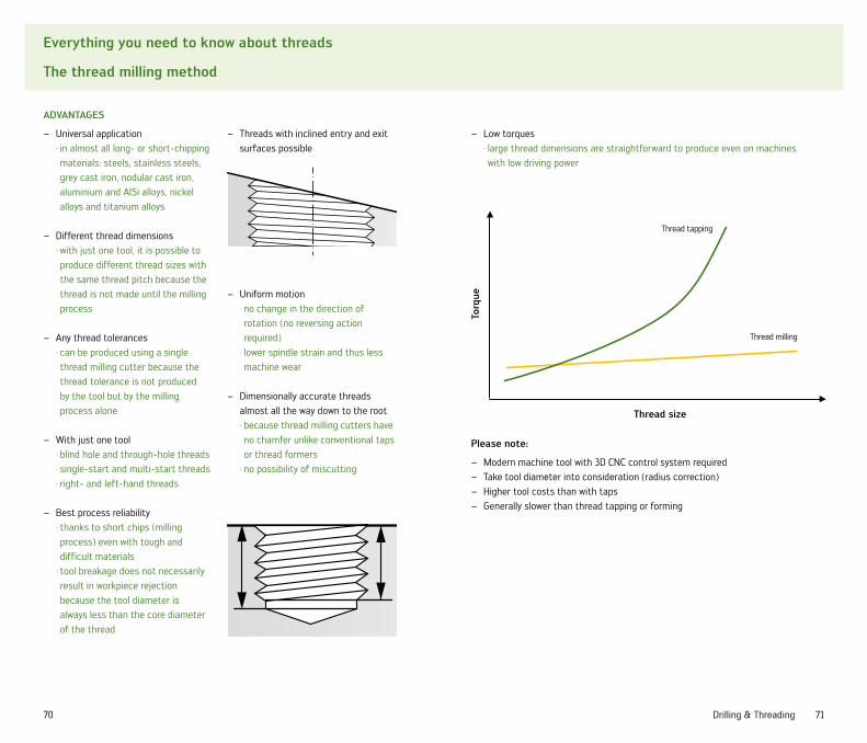
Threads with inclined entry and exit –surfaces possible
Uniform motion –· no change in the direction of rotation (no reversing action required)
· lower spindle strain and thus less machine wear
Dimensionally accurate threads –almost all the way down to the root · because thread milling cutters have no chamfer unlike conventional taps or thread formers
· no possibility of miscutting
ADvAnTAGes
Universal application –· in almost all long- or short-chipping materials: steels, stainless steels, grey cast iron, nodular cast iron, aluminium and AlSi alloys, nickel alloys and titanium alloys
Different thread dimensions –· with just one tool, it is possible to produce different thread sizes with the same thread pitch because the thread is not made until the milling process
Any thread tolerances –· can be produced using a single thread milling cutter because the thread tolerance is not produced by the tool but by the milling process alone
With just one tool –· blind hole and through-hole threads· single-start and multi-start threads· right- and left-hand threads
Best process reliability –· thanks to short chips (milling process) even with tough and difficult materials
· tool breakage does not necessarily result in workpiece rejection because the tool diameter is always less than the core diameter of the thread
Please note:
Modern machine tool with 3D CNC control system required –Take tool diameter into consideration (radius correction) –Higher tool costs than with taps –Generally slower than thread tapping or forming –
Low torques –· large thread dimensions are straightforward to produce even on machines with low driving power
Thread size
Torq
ue
Thread tapping
Thread milling

72 73Drilling & Threading
Additional information
X·treme Plus cutting data
Material to be machined Cutting speed vc (m/min) Feed f (mm) for Ø (mm)
Material group Designation
Operating range
Standard value 3-4 4-6 6-9 9-14 14-20
1.1.1 Free cutting steel 160-230 190 0.10-0.15 0.14-0.22 0.2-0.32 0.29-0.42 0.38-0.51
1.1.2 Soft construction steels up to 550 N/mm² 160-230 190 0.10-0.14 0.13-0.21 0.19-0.3 0.27-0.39 0.35-0.48
1.1.3 Low-alloy steel and cast steel 550 - 700 N/mm² 140-210 171 0.09-0.13 0.12-0.19 0.18-0.28 0.25-0.36 0.33-0.44
1.2 Low-alloy steel and cast steel 700 - 1,000 N/mm² 120-170 143 0.08-0.12 0.11-0.18 0.16-0.26 0.23-0.33 0.3-0.41
1.3 Steel 1,000 - 1,300 N/mm² 100-140 114 0.07-0.10 0.09-0.15 0.14-0.21 0.19-0.28 0.25-0.34
1.4 Steel 1,300 - 1,600 N/mm² 60-90 72 0.04-0.06 0.05-0.09 0.08-0.13 0.12-0.17 0.15-0.21
1.5.1 Steel, hardened 45 - 55 HRC 50-80 65 0.03-0.05 0.04-0.07 0.07-0.1 0.09-0.13 0.12-0.16
1.6.1 Tool steel, non-alloyed 100-140 114 0.07-0.11 0.1-0.16 0.15-0.24 0.21-0.3 0.28-0.38
1.6.2 Tool steel, low-alloyed 100-140 114 0.07-0.1 0.1-0.16 0.14-0.22 0.2-0.29 0.26-0.36
1.6.3 Tool steel, high-alloyed 70-100 82 0.06-0.09 0.08-0.13 0.12-0.19 0.17-0.25 0.23-0.31
1.7.1 Stainless steel, ferritic, martensitic 40-60 47 0.06-0.09 0.08-0.13 0.12-0.19 0.17-0.25 0.23-0.31
1.7.2 Stainless steel, austenitic, sulphurised 60-90 74 0.08-0.11 0.1-0.17 0.15-0.24 0.22-0.32 0.29-0.39
1.7.3 Stainless steel, austenitic 40-60 47 0.04-0.06 0.06-0.09 0.09-0.14 0.12-0.18 0.16-0.22
1.7.4 Stainless steel, hardened 40-60 47 0.04-0.06 0.06-0.09 0.09-0.14 0.12-0.18 0.16-0.22
2.1 Ni and Co alloys up to 900 N/mm² 30-50 39 0.04-0.05 0.05-0.08 0.07-0.11 0.1-0.15 0.13-0.18
2.2 Ni and Co alloys 900 - 1,200 N/mm² 20-30 29 0.03-0.04 0.04-0.06 0.05-0.09 0.08-0.11 0.1-0.14
2.3 Ni and Co alloys over 1,200 N/mm² 20-20 18 0.03-0.04 0.04-0.06 0.05-0.09 0.08-0.11 0.1-0.14
3.1 Cast iron GG10-GG20 120-180 148 0.13-0.19 0.17-0.28 0.26-0.41 0.37-0.53 0.48-0.65
3.2 Cast iron GG25 - GG40 100-150 124 0.13-0.19 0.17-0.28 0.26-0.41 0.37-0.53 0.48-0.65
3.3.1 Cast iron GGG40 - GGG50 130-180 152 0.13-0.19 0.17-0.28 0.26-0.41 0.37-0.53 0.48-0.65
3.3.2 Cast iron GGG60-GGG80 100-140 114 0.11-0.17 0.15-0.25 0.23-0.36 0.33-0.47 0.42-0.57
6.1 Titanium and titanium alloys up to 700 N/mm² 60-90 76 0.05-0.08 0.07-0.11 0.1-0.16 0.15-0.21 0.19-0.26
6.2 Titanium alloys over 700 N/mm² 50-80 66 0.04-0.06 0.06-0.09 0.09-0.14 0.12-0.18 0.16-0.22
The values listed apply to a drilling depth of max. 3 x d.The data should be reduced by approx. 5 % for values over 5 x d.
Only the most important materials are listed here. For additional materials and precise values, please refer to TEC+CCS.

74 75Drilling & Threading
eCo-HT tap cutting data
Additional information
X·treme Plus driving power
2 4 6 8 10 12 14 16 18 20
Diameter d (mm)
feed
for
ce f
v (k
n)
14
12
10
8
6
4
2
0
Construction steel (370 - 550 N/mm²)
Tempering steel (700 - 1,000 N/mm²)
High tensile steel (1,000 - 1,300 N/mm²)
Austenitic stainless steel
Cast iron (GG25 - GG35)
Cast iron (GGG40 - GGG50)
Material to be machined THvc
(m/min)
BHvc
(m/min)
Material group Designation THL THL
1. steel 1.2 construction / case-hardened steel E,M 40-50 25-35
1.3 carbon steel E,M 35-45 20-30
1.4 alloyed / tempered E,O,M 25-35 15-25
1.5 alloyed / tempered O,E 15-20 10-15
1.6.1 alloyed / tempered O,E 10-12 7-10
2. stainless and acidproof steel 2.1 sulphurised E,O,M 10-15 7-12
2.2 austenitic E,O,M 10-12 7-10
2.3 ferritic, austenitic, martensitic E,O,M 7-10 5-7
2.4 highly heat-resistant E,O,M 6-8 3-5
3. cast iron 3.1 grey cast iron E,D 20-30 15-20
3.2 grey cast iron E,D 15-20 10-15
3.3 tempered nodular cast iron O,E,M 25-35 15-25
3.4 tempered nodular cast iron O,E,M 10-20 7-15
3.5 cast iron, vermicular E,D 10-15 7-12
6. copper 6.1 pure copper E 15-20 10-15
6.2 brass, bronze, red brass, short-chipping E 40-60 30-40
6.3 brass, long chipping, wrought alloy E 30-40 20-30
7. aluminium, magnesium
7.2 Al, alloyed, Si<0.5 %, wrought and cast alloys E 50-60 35-45
7.3.1 Al, alloyed, Si>=0.5 %<4 %, wrought and cast alloys E 35-40 20-25
7.3.2 Al, alloyed, Si>=4 %<10 %, wrought and cast alloys E 30-35 20-25
E = EmulsionO = OilM = Minimum quantity lubricationD = Dry / compressed airTH = Through holeBH = Blind hole
Our expert system, TEC+CCS, will recommend the cutting data to suit your machining needs.
All values refer to recommended cutting data for the respective materials.
2 4 6 8 10 12 14 16 18 20
Diameter d (mm)
Dri
ving
pow
er P
(kn
)
35
30
25
20
15
10
5
0
Construction steel (370 - 550 N/mm²)
Tempering steel (1,000 - 1,300 N/mm²)
High tensile steel (1,000 - 1,300 N/mm²)
Austenitic stainless steel
Cast iron (GG25 - GG35)
Cast iron (GGG40 - GGG50)

76 77Drilling & Threading
Additional information
TeC+CCs expert system
The Walter expert system, which incorporates the Walter Titex and Walter Prototyp brands, has become an indispensable software tool for many metalworkers worldwide, helping them to select and make economical use of milling, drilling and threading tools. for over 15 years, TeC+CCs has been considered a problem solver that the machining world can depend on.
order the latest version on CD-roM free of charge now.You will find further information at www.walter-tools.com/service.
TeC+CCs offers the following features:
Tooling recommendation and display –of cutting data after user entry of the machining taskElectronic catalogue of cutting data –Customisable database of special –tools and determination of associ-ated cutting and performance data (CCS)Selection of appropriate core-hole –drills via direct link between CCS and TEC
Modification of tools, ability to –store tools, and determination of associated cutting and performance data (CCS)Ordering process, net prices, – economic viability analyses, DXF Generator for tool drawings, generation of NC programs for thread milling and much more …
TeC+CCs – your expert system for economical milling, drilling and threading.

78 79Drilling & Threading
Additional information
Thread tapping core diameters
M ISO metric coarse pitch thread
Designation(DIN 13)
Female thread core diameter(mm)
Drill size(mm)
min 6H max M 2 1.567 1.679 1.60
M 2.5 2.013 2.138 2.05
M 3 2.459 2.599 2.50
M 4 3.242 3.422 3.30
M 5 4.134 4.334 4.20
M 6 4.917 5.153 5.00
M 8 6.647 6.912 6.80
M 10 8.376 8.676 8.50
M 12 10.106 10.441 10.20
M 14 11.835 12.210 12.00
M 16 13.835 14.210 14.00
M 18 15.294 15.744 15.50
M 20 17.294 17.744 17.50
M 24 20.752 21.252 21.00
M 27 23.752 24.252 24.00
M 30 26.211 26.771 26.50
M 36 31.670 32.270 32.00
M 42 37.129 37.799 37.50
MF ISO metric fine pitch thread
Designation(DIN 13)
Female thread core diameter(mm)
Drill size(mm)
min 6H max M 6 x 0.75 5.188 5.378 5.25
M 8 x 1 6.917 7.153 7.00
M 10 x 1 8.917 9.153 9.00
M 10 x 1.25 8.647 8.912 8.75
M 12 x 1 10.917 11.153 11.00
M 12 x 1.25 10.647 10.912 10.75
M 12 x 1.5 10.376 10.676 10.50
M 14 x 1.5 12.376 12.676 12.50
M 16 x 1.5 14.376 14.676 14.50
M 18 x 1.5 16.376 16.676 16.50
M 20 x 1.5 18.376 18.676 18.50
M 22 x 1.5 20.376 20.676 20.50
UNC (Unified Coarse Thread)
Designation(ASME B 1.1)
Female thread core diameter(mm)
Drill size(mm)
min 2B max No. 2-56 1.694 1.872 1.85
No. 4-40 2.156 2.385 2.35
No. 6-32 2.642 2.896 2.85
No. 8-32 3.302 3.531 3.50
No. 10-24 3.683 3.962 3.901/4 -20 4.976 5.268 5.105/16 -18 6.411 6.734 6.603/8 -16 7.805 8.164 8.001/2 -13 10.584 11.013 10.805/8 -11 13.376 13.868 13.503/4 -10 16.299 16.833 16.50
UNF Unified Fine Thread
Designation(ASME B 1.1)
Female thread core diameter(mm)
Drill size(mm)
min 2B max No. 4-48 2.271 2.459 2.40
No. 6-40 2.819 3.023 2.95
No. 8-36 3.404 3.607 3.50
No. 10-32 3.962 4.166 4.101/4 -28 5.367 5.580 5.505/16 -24 6.792 7.038 6.903/8 -24 8.379 8.626 8.501/2 -20 11.326 11.618 11.505/8 -18 14.348 14.671 14.50
G Pipe thread
Designation(DIN EN ISO 228)
Female thread core diameter(mm)
Drill size(mm)
min max G 1/8 8.566 8.848 8.80
G 1/4 11.445 11.890 11.80
G 3/8 14.950 15.395 15.25
G 1/2 18.632 19.173 19.00
G 5/8 20.588 21.129 21.00
G 3/4 24.118 24.659 24.50
G 1 30.292 30.932 30.75

80 81Drilling & Threading
Additional information
Thread forming core diameters
M ISO metric coarse pitch thread
Designation(DIN 13)
Female thread core diameter(DIN 13-50) (mm)
Pilot drill size(mm)
min 7H max M 1.6 1.221 - 1.45
M 2 1.567 1.707 1.82
M 2.5 2.013 2.173 2.30
M 3 2.459 2.639 2.80
M 3.5 2.850 3.050 3.25
M 4 3.242 3.466 3.70
M 5 4.134 4.384 4.65
M 6 4.917 5.217 5.55
M 8 6.647 6.982 7.40
M 10 8.376 8.751 9.30
M 12 10.106 10.106 11.20
M 14 11.835 12.310 13.10
M 16 13.835 14.310 15.10
MF ISO metric fine pitch thread
Designation(DIN 13)
Female thread core diameter(DIN 13-50) (mm)
Pilot drill size(mm)
min 7H max M 6 x 0.75 5.188 5.424 5.65
M 8 x 1 6.917 7.217 7.55
M 10 x 1 8.917 9.217 9.55
M 12 x 1 10.917 11.217 11.55
M 12 x 1.5 10.376 10.751 11.30
M 14 x 1.5 12.376 12.751 13.30
M 16 x 1.5 14.376 14.751 15.30
Protodyn ECO plus thread former – the ideal addition to the ECO-HT tap range.

82 83Drilling & Threading
Additional information
Troubleshooting: drilling
Broken CuTTinG eDGe Corners
Excessive corner wear causing –corners to break off· Recondition promptly
Workpiece springs up during through –hole drilling, tool therefore latches· Reduce feed rate for through hole drilling (-50 %)
Inclined exit during through hole –drilling results in interrupted cut· Reduce feed rate for through drilling (-50 %)
Through hole drilling of a cross hole –results in interrupted cut· Reduce feed rate for through drilling of the cross hole (-50 % to -70 %)
Centring with too small a point angle, –tool therefore drilling corner first· Precentre with point angle > point angle of drill
Mechanical overload of corner –cutting edges· Reduce feed rate
Material has hard surface –· Reduce feed rate and cutting speed for drilling on entry (and, if appli-cable, on exit if hard on both sides) (-50 % in both cases)
Material too hard –· Use special tool for hard/hardened materials
CuTTinG eDGe Corners DesTroYeD
Excessive corner wear –· Recondition promptly
Cutting edge corners overheating –· Reduce cutting speed
CenTre reGion DesTroYeD
Excessive wear in the centre causing –it to spall· Recondition promptly
Mechanical overload of point –· Reduce feed rate
Material has hard surface –· Reduce feed rate and cutting speed for drilling on entry (-50 %)
Material too hard –· Use special tool for hard/hardened materials

84 85Drilling & Threading
Additional information
Troubleshooting: drilling
DriLL BiT BreAkAGe
Excessive wear causing breakage due –to overloading· Recondition promptly
Crowding –· Check that the flute length is at least equal to drilling depth +1.5 x d
· Use a drill bit with better chip transport properties
Drill bit wanders on entry (e.g. because bit too long, –entry surface not flat, entry surface inclined)· Centre-mark
On lathes: alignment error between rotary axis and –drill axis· Instead of a solid carbide tool, use an HSS(-E) drill bit or a drill bit with steel shank
Workpiece not clamped with adequate stability –· Improve workpiece security
Handling error –· Keep tools in original packaging· Keep tools apart/prevent contact
sPALLinG on CYLinDriCAL LAnDs
HoLe Too LArGe
Excessive centre wear or irregular wear –· Recondition promptly
Drill bit wanders on entry (e.g. because bit too long, –entry surface not flat, entry surface inclined)· Centre-mark
Radial runout of the chuck or –machine spindle· Use a hydraulic expansion chuck or shrink-fit chuck
· Check and repair the machine spindle
Workpiece not clamped with adequate stability –· Improve workpiece security
ø ø ø
ø ø ø
HoLe Too sMALL
Excessive wear of cylindrical lands or corners –· Recondition promptly
Hole not round –· Reduce cutting speed

86 87Drilling & Threading
Additional information
Troubleshooting: drilling
Poor CHiP forMATion
Excessive wear of the main cutting edge –affecting chip formation· Recondition promptly
Chips too thin because feed rate too low –· Increase feed rate
Inadequate cooling causing the chips to overheat –· Use internal cooling instead of external · Increase the pressure of the internal coolant supply
· Incorporate dwell periods into the program if necessary
enTrY PosiTion ouTsiDe ToLerAnCe
Excessive centre wear –· Recondition promptly
Drill bit wanders on entry –(e.g. because bit too long, entry surface not flat, entry surface inclined)· Centre-mark
Burr on THe Bore eXiT
Excessive wear of the corner cutting edge –· Recondition promptly
Poor surfACe finisH
Excessive wear of the corner cutting edge –or cylindrical lands· Recondition promptly
Crowding –· Check that the flute length is at least equal to drilling depth +1.5 x d
· Use a drill bit with better chip transport properties
ø ø ø
ø ø ø
ø ø ø

88 89Drilling & Threading
Additional information
Troubleshooting: threading
rADiAL MisCuTTinG of THreADs
Tool also cutting in the core –· Select a large core diameter· Improve chip removal· Use a greater helix angle
Cutting edge geometry unsuitable –for the work· Select an appropriate tool recommended by the catalogue or TEC+CCS
Core hole position or angle error –· Check workpiece security – reduce feed rate on entry if necessary
Tap exhibits cold welding –· Use a new tap,· Improve lubrication (cooling)· Select a suitable surface treatment or coating
Inadequate internal coolant supply –· Improve lubricating agent or supply
Incorrect tool type –· Select an appropriate tool recommended by the catalogue or TEC+CCS
Tolerance not identical to the – tolerance specified on the drawing or thread gauge· Use a tap with appropriate tolerance
THreAD Too sHorT
AXiAL MisCuTTinG of THreADs
BeLL MouTH
TooL Life Too sHorT
Tap not cutting to pitch specification –· Reduce feed rate by approximately 5 - 10 % (for chucks with length compensation)
Contact pressure too low/high –· Adjust contact pressure
Core hole position or angle error –· Check workpiece security – reduce feed rate on entry if necessary
Incorrect contact pressure –· With length compensating chuck, switch to expansion
Unsuitable cutting edge geometry –· Select an appropriate tool recommended by the catalogue or TEC+CCS
Core hole strain-hardened due to –blunt preparatory tool· Change drill bit/regrind promptly

90 91Drilling & Threading
Thread tapping/forming calculation formulae
Additional information
Drilling calculation formulas
speed
n [rpm] n =vc · 1,000
[rpm]d1 · ∏
Cutting speed
vc [m/min] vc =d1 · ∏ · n
[m/min]1,000
feed per revolution
f [mm] f = fz · Z [mm]
feed rate
vf [mm/min] vf = f · n [mm/min]
Metal removal rate
Q [cm³/min] Q =vf · ∏ · d1² [cm³/min]
1,000
speed
n [rpm] n =vc · 1,000
[rpm]d1 · ∏
Cutting speed
vc [m/min] vc =d1 · ∏ · n
[m/min]1,000
feed rate
vf [mm/min] vf = p · n [mm/min]

92 93Drilling & Threading
Additional information
Walter Titex CATexpress
Your ADvAnTAGes
Cost savings thanks to reduced storage –More flexibility thanks to 2 weeks lead time –Fast feedback thanks to quote returned within 24 hours –Easy to use thanks to cutting data recommendations –Reduction in errors in tool design as there is no need to place the order –until the desired component has been definedAll CATexpress tools are manufactured in Germany to meet proven –Walter Titex quality standards
WHAT is CAT eXPress?
CATexpress is Walter's express ordering and delivery service for Walter Titex special tools. CATexpress covers a defined range of special tools. For these tools, we guarantee a short lead time of a maximum of two weeks from the time of order intake.
WHAT's PossiBLe?
Carbide drilling and reaming tools, –e.g. Alpha® 2, Alpha® 4,X·treme Plus (+1 week), XD technology, –XD-Pilot, etc.Spiral and straight-fluted tools –Batch sizes of 3 to 50 pce. –Diameters from 3 mm to 20 mm –Drilling depths down to 35 x d –Stepped tools with up to two 2 steps –Coatings, e.g. TFL, TFT, TFP, etc. –
HoW Does iT Work?
Complete our special forms for defining –your special toolsThese forms are available from your –contact in the inhouse/field serviceYou will find further information –and our forms at www.walter-tools.de
eXAMPLes of CATeXPress sPeCiAL soLuTions
Alpha® Jet step drill with 180° “form e” point
Twisted step drill
X·treme Plus
X·treme DH, XD technology
X·treme Pilot 180, pilot drill with XD technology

94 95Drilling & Threading
Additional information
Walter reconditioning service
WALTer TiTeX AnD WALTer ProToTYP MiLLinG, DriLLinG AnD reAMinG TooLs of oriGinAL quALiTY.
ToP quALiTY, eAsY HAnDLinG AnD ProMPT DeLiverY.
Our Reconditioning Service for Walter Titex and Walter Prototyp tools make an important contribution to reducing your production costs. On the one hand, you obtain tools that are as good as new but cost almost a third of the price of a brand new product. On the other hand, you save around 50 % of tool costs with the third regrinding – especially in the case of high-quality, high-tech tools.
This means:100 % original quality, 50 % lower costs.
With our Reconditioning Service, not only do you save costs and time, you also spare resources. This is how it works: You decide which tools need to be reground and place them in our “Redbox”. We arrange for its collection and then return your tools free of charge and restored to their original quality a few days later.
reGrinDinG AnD reCoATinG PAYs off:
new tool 1st regrinding 2nd regrinding 3rd regrinding
100 %
75 %
50 %
25 %
0 %
-50 %
RE
GROUND
AND COATED
our DeLiverY serviCe
Easy handling with standardised delivery note and barcode stickers –Regrinding/recoating of catalogue tools to restore original geometry –and coatingRegrinding of special tools in accordance with drawing (price on request) –
Pack the tools to be reground in the Walter Titex and Walter Prototyp shipping box provided free of charge
Collection of shipping box arranged with one phone call
You receive your tools restored to original Walter Titex and Walter Prototyp quality
Regrinding to the highest quality standards by our experts
Delivery of the reconditioned tools
Recoating for maximum performance
Tool costs

_WALTER WORLDWIDE
How to find us.
EUROPE
Walter Deutschland GmbHFrankfurt, Germany
Werner schmittPkD-Werkzeug GmbHNiefern-Öschelbronn, Germany
TDM systems GmbHTübingen, Germany
Walter (schweiz) AGSolothurn, Switzerland
Walter Benelux n.v./s.A.Zaventem, Belgium
Walter GB Ltd.Bromsgrove, Great Britain
Walter italia s.r.L.Fino Mornasco (CO), Italy
Walter franceSoultz-sous-Forêts, France
Walter Tools iberica s.A.u.El Prat de Llobregat, Spain
Walter norden ABHalmstad, Sweden
Walter CZ spol.sr.o.Kurim, Czech Republic
Walter Polska sp.z.o.o.Warsaw, Poland
Walter Hungária kft.Budapest, Hungary
Walter Austria GmbHVienna, Austria
sC Montanwerke Walter srLTimisoara, Romania
Montanwerke Walter GmbH - Podruz̆nica Trgovina slovenijaMiklavz̆na Dravskem Polju, Slovenia
Walter LLCSt. Petersburg, Russia
Walter slowakei, o.z.Nitra, Slovakia
Walter kesici Takimlar sanayi ve Ticaret Limited sirketi Istanbul, Turkey
HEADQUARTERS Walter AGTübingen, Germany

www.walter-tools.com
NORTH AMERICA
Walter USA, INC.Waukesha, WI, USA
TDM Systems Inc.Schaumburg, IL, USA
Walter Tools S.A. de C.V.Tlalnepantla, Mexico
Walter [email protected]
SOuTH AMERICA
Walter do Brasil Ltda.Sorocaba, Brazil
Walter Argentina S.A.Capital Federal, Argentina
ASIA PACIFIC REGION
Walter Wuxi Co. Ltd.Wuxi, China
Walter AG Singapore Pte Ltd.Singapore
Walter Korea Ltd.Ansan, Korea
Walter Tools India Pvt. Ltd.Pune, India
Walter Tooling Japan KKNagoya, Japan
Walter (Thailand) Co. Ltd.Bangkok, Thailand
Walter Malaysia Sdn. Bhd.Selangor, Malaysia
Walter Australia Pty. Ltd.Victoria, Australia
Walter New Zealand Ltd.Christchurch, New Zealand

Prin
ted
in G
erm
any
583
8413
(08/
2009
) EN
Walter AG
Derendinger Straße 53, 72072 Tübingen Postfach 2049, 72010 Tübingen Germany
www.walter-tools.com
Walter GB LTD.Bromsgrove, England+44 (0) 1527 839450 [email protected]
Walter Kesici Takimlar Sanayi ve Ticaret Limited SirketiIstanbul, Turkey+90 (216) 528 1900 Pbx [email protected]
Walter Wuxi Co. Ltd.Wuxi, Jiangsu, P.R. China+86 (0) 510 824-19399 [email protected]
Walter AG Singapore Pte Ltd+65 67736180 [email protected]
Walter Korea Ltd.Ansan, Kyungki-do, Korea+82 (0) 31 3646-100 [email protected]
Walter Tools India Pvt. Ltd.Pune, India+91 20 27145028 [email protected]
Walter (Thailand) Co., Ltd.Bangkok, Thailand+662 (0) 6811305 [email protected]
Walter Malaysia Sdn. Bhd.Selangor D.E., Malaysia+603-5635 8931 [email protected]
Walter Australia Pty. Ltd.Victoria, Australia+61 (0)3 8793-1000 [email protected]
Walter New Zealand Ltd.Christchurch, New Zealand+64 (0)800 740757 [email protected]
Walter Tooling Japan KKNagoya, Japan+81 (0)52 723 5800 [email protected]
Walter USA, Inc.Waukesha (WI), USA+1 800-945-5554 [email protected]
TDM Systems Inc.Schaumburg (IL), USA847-605-1269 [email protected]
Walter Tools S.A. de C.V.Tlalnepantla, Estado de México+52 (55) 5365-6895 [email protected]
Walter [email protected]