HANDBOOK - Castel Srl · Castel offers the Refrigeration and Air Conditioning Market and...
76
HANDBOOK SOLENOID VALVES Ed. 2017
Transcript of HANDBOOK - Castel Srl · Castel offers the Refrigeration and Air Conditioning Market and...

SOLENOID VALVESVS-ED 01/2017 - ENG 1
HANDBOOKSOLENOID VALVES
Ed. 2017

SOLENOID VALVESVS-ED 01/2017 - ENG2

SOLENOID VALVESVS-ED 01/2017 - ENG 3
THE NATURAL DEVELOPMENT OF QUALITYHaving achieved the goal of fifty-five years working in the Refrigeration and Air Conditioning Industry, Castel’s range of quality products is well known and highly appreciated around the world. Quality is the product of our Company philosophy and marks every step of the production cycle. It is certified by the company’s Quality Management System (certified by TUV SUD in accordance with the UNI EN ISO 9001:2008 standard), as well as by the various product certifications of compliance with European Directives and European and extra-European Quality Marks.Product quality is connected with the quality of manufacturing. We produce on high-tech machinery and updated automatic production lines, operating in compliance with the current safety and environmental protection standards.Castel offers the Refrigeration and Air Conditioning Market and Manufacturers tested certified products suitable for use with the HCF and HFO refrigerants currently used in the Refrigeration & Air Conditioning Industry.Based on the experience gained in the refrigeration field using fluorinated fluids, Castel is proud to present the Refrigeration and Air Conditioning Market and Manufacturers two complete lines of products developed and proven for use in systems using natural refrigerants: hydrocarbons (HC fluids) and carbon dioxide (R744).
TABLE OF CONTENTS
CHAPTER 1 Normally-closed solenoid valves For refrigeration plants that use HCFC, HFC or HFO refrigerants
CHAPTER 2 High-temperature normally-closed solenoid valves For refrigeration plants that use HFC or HFO refrigerants
CHAPTER 3 Normally-closed pulse solenoid valves For refrigeration plants that use HFC or HFO refrigerants
CHAPTER 4 Normally-open solenoid valves For refrigeration plants that use HCFC, HFC or HFO refrigerants
CHAPTER 5 Normally-closed solenoid valves For refrigeration plants that use HC refrigerants
CHAPTER 6 Normally-closed solenoid valves For refrigeration plants that use the R744 refrigerant
CHAPTER 7 Normally-closed solenoid valves, UL-approved For refrigeration plants that use HCFC, HFC or HFO refrigerants
CHAPTER 8 Normally-closed solenoid valves For industrial applications
CHAPTER 9 Standard coils and connectors
CHAPTER 10 Coils and connectors, ATEX-approved For the solenoid valves in CHAPTER 5
CHAPTER 11 Coils and connectors, UL-approved For the solenoid valves in CHAPTER 7
CHAPTER 12 “SMART CONNECTOR” system
CHAPTER 13 Magnetic tool
06
15
24
28
36
41
44
54
59
64
66
71
75

SOLENOID VALVESVS-ED 01/2017 - ENG4

SOLENOID VALVESVS-ED 01/2017 - ENG 5
DIRECTIVE 2014/68/EU ISSUED OF THE EUROPEAN PARLIAMENT AND OF THE COUNCIL OF 15 MAY 2014 ON PRESSURE EQUIPMENTDirective 2014/68/EU (PED Recast) applies to the design, manufacture and evaluation of compliance of pressure equipment and assemblies with a maximum allowable pressure, PS, greater than 0.5 bar excluding the cases listed in Article 1, Paragraph 2 of the Directive.Directive 2014/68/EU was transposed into the Italian legal system by Legislative Decree No. 26 dated 15 February 2016, published in the Official Journal of the Republic of Italy No. 53 of 4 March 2016.The revised PED Recast Directive repeals previous Directive 97/23/EC. More specifically:• Article 13 of the PED Recast Directive, regarding the classification of pressure equipment, came into force as of 1 June 2015 and repeals Article 9 of the previous PED Directive.• All other articles of the PED Recast Directive are in force as of 19 July 2016, repealing all articles of the previous PED directive.All solenoid valves illustrated in this technical handbook are considered “Pressure Accessories” according to the definition provided in Article 2, Point 5 of said Directive and are subject to the classification indicated in Article 4, Points 1.c) and 3 of the same Directive.
ExTERNAL LEAkAgEAll the products illustrated in this Handbook are submitted, one by one, to tightness tests as well as specific functional tests. The allowable external leakage, measurable during the test, complies with the requirements of standards:• EN 12284 : 2003 – Refrigerating systems and heat pumps - Valves - Requirements, testing and marking• EN 16084 : 2011 – Refrigerating systems and heat pumps - Qualification of tightness of components and joints
PRESSURE CONTAINMENTAll the products illustrated in this Handbook, if submitted to hydrostatic testing, guarantee a pressure strength at least equal to 1.43 x PS in compliance with Directive 2014/68/EU.All the products illustrated in this Handbook, if submitted to burst testing, guarantee a pressure strength at least equal to 3 x PS in compliance with standard EN 378-2:2016.All the UL-certified products illustrated in this Handbook, if submitted to burst testing, guarantee a pressure strength at least equal to 5 x MWP in compliance with standard UL 429.
WEIgHTThe weight of the items listed in this Handbook includes packaging and is not binding.
WARRANTYAll Castel products are covered by a 12-month warranty. This warranty covers all products or parts thereof that turn out to be defective within the warranty period. In this case, at his own expense, the customer shall return the defective item with a detailed description of the claimed defects. The warranty does not apply if the defect of the Castel product is due to mistakes by the customer or by third parties, such as incorrect installation, use contrary to Castel instructions, or tampering. In the event of defects found in its products, Castel will only replace the defective goods and will not refund damages of any kind. Castel reserves the right to make changes or modifications to its products at any time without prior notice.
The products listed in this handbook are protected according to law.
SOLENOID VALVES

SOLENOID VALVESVS-ED 01/2017 - ENG6
CHAPTER 1NORMALLY-CLOSED SOLENOID VALVES
FOR REFRIGERATION PLANTS THAT USE HCFC, HFC OR HFO REFRIGERANTS
The valves series 1020 and 1028 are direct acting valves. Their operation depends only on the magnetic field produced by the current flow into the coil. Opening/closing of main valve seat, the only seat, is directly controlled by the mobile plunger.These valves can work with zero pressure differential.
The valves series 1064 ; 1068 ; 1070 ; 1078 (excluded /11 , /13 , and /M42) ; 1079 (excluded /13 , /M42 , and /17) ; 1090 ; 1098 (excluded /9) ; 1099 (excluded /11) are pilot-operated diaphragm solenoid valves. Their operation depends not only on the magnetic field produced by the current flow into the coil, but also on a minimum inlet pressure, which is necessary to:• open the diaphragm and keep it lifted off the main
opening• close the diaphragm and ensure the tightness on the
main openingOpening/closing of main valve seat is controlled by the diaphragm while opening/closing of pilot seat is controlled by the mobile plunger of the coil.These valves cannot work with zero differential pressure.
The valve series 1034 ; 1038 ; 1040 ; 1048 ; 1049 ; 1050 ; 1058 ; 1059 ; 1078 (/11 , /13 , /M42) ; 1079 (/13 , /M42 , /17) ; 1098/9 ; 1099/11 are piston pilot-operated valves. Their operation depends not only on the magnetic field produced by the current flow into the coil, but also on a minimum inlet pressure, which is necessary to:• open the piston and keep it lifted off the main opening• close the piston and ensure the tightness on the main
openingOpening/closing of main valve seat is controlled by the piston, while opening/closing of pilot seat is controlled by the mobile plunger of the coil.
APPLICATIONThe solenoid valves illustrated in this chapter are designed for installation on commercial refrigeration systems and on civil and industrial air conditioning plants that use the following refrigerant fluids:• HCFC (R22)• HFC (R134a , R404A , R407C , R410A , R507)• HFO and HFO/HFC mixtures (R1234ze , R448A , R449A
R450A , and R452A)belonging to Group 2, as defined in Article 13, chapter 1, Point (b) of Directive 2014/68/EU, with reference to EC Regulation No. 1272/2008.Furthermore, the same solenoid valves, up to DN 25, that is models 1078*9, 1098/9, 1079/11 and 1099/11, can also be installed on systems using the following refrigeration fluids:• HFC (R32)• HFO (R1234yf)classified as A2L in the ASHRAE 34-2013 standard, and belonging to Group 1, as defined in Article 13, chapter 1, Point (a) of Directive 2014/68/EU, with reference to EC Regulation No. 1272/2008.For specific applications with refrigerant fluids not listed above, please contact Castel Technical Department.
OPERATIONThe coils listed in this chapter are normally closed (NC). This means that when the coil is not energised, the plunger closes the fluid passage. When the coil is energised, the plunger opens the valve seat connecting the inlet to the outlet.All the above indicated valves are sold in the version without coil (with the S suffix), and in the version with coil series 9300, type HF2 - “FAST LOCK” (A6 suffix with coil 9300/RA6-220/230 VAC and A7 suffix with coil 9300/RA7 - 240 VAC).

SOLENOID VALVESVS-ED 01/2017 - ENG 7
These valves cannot work with zero differential pressure.
CONSTRUCTIONThe main parts that make up the solenoid valves presented in this chapter are constructed with the following materials:• Hot forged brass EN 12420 – CW 617N for body and
cover• Copper tube EN 12735-1 – Cu-DHP for solder
connections• Austenitic stainless steel EN 10088-2 – 1.4303 for
enclosure where the plunger moves• Ferritic stainless steel EN 10088-3 – 1.4105 for the
plunger• Austenitic stainless steel EN ISO 3506 – A2-70 for
tightening screws between body and cover.• Chloroprene rubber (CR) for the outlet seal gaskets• P.T.F.E. for seat gaskets
INSTALLATIONAll the valves in this chapter can be installed on the three main branches of a plant (hot gas line, liquid line, and suction line), while respecting the limits of use indicated in TABLES 1 and 2 and the capacities indicated in TABLE 4.TABLES 1 and 2 show the following functional characteristics of a solenoid valve:• Connection dimensions• PS: maximum allowable pressure of the refrigerant• TS: maximum / minimum allowable temperature of the
refrigerant• TA: maximum / minimum allowable ambient
temperature• Kv: discharge factor• minOPD: minimum Opening Pressure Differential. This
is the minimum pressure differential between inlet and outlet at which a pilot-operated solenoid valve can
open and stay opened or close and maintain the seal.• MOPD: maximum opening pressure differential
according to AHRI STANDARD 760:2014. This is the maximum pressure differential between inlet and outlet at which a solenoid valve can open.
Before connecting the valve to the pipe, it is advisable to make sure that the refrigerating system is clean. In fact, valves with P.T.F.E. gaskets, and particularly piston valves, are sensitive to dirt and debris. Furthermore, check that the flow direction in the pipe corresponds to the arrow stamped on the valve body. All the valves can be mounted in any position so long as the coil does not point downwards. The brazing of valves with solder connections should be carried out with care, using a low melting point filler material. It is not necessary to disassemble the valves before brazing, but it is important to avoid direct contact between the torch flame and the valve body, which could be damaged and compromise the proper functioning of the valve.Before connecting a valve to the electrical system, be sure that the line voltage and frequency correspond to the values marked on the coil.
TRACEABILITYDirect action valves in series 1020 and 1028 are identified by laser marking on the valve sleeve of the mobile plunger. This marking includes the following data: valve code, refrigerants, PS, TS, and production lot.
The pilot-operated diaphragm and piston valves, series 1034, 1038, 1040, 1048, 1049, 1050, 1058, 1059, 1064, 1068, 1070, 1078, 1079, 1090, 1098, and 1099 are identified by a plastic label fit on the valve sleeve of the mobile plunger (under the coil when indicated). This label includes the following data: valve code, refrigerants, PS, TS, and production lot.

SOLENOID VALVESVS-ED 01/2017 - ENG8
# = S , A6 , A7
(1) Temperature peaks of 120 °C are allowed during defrosting(2) Temperature peaks of 130 °C are allowed during defrosting(3) Check TAmin of the chosen coil
TABLE 1: General characteristics of NC valves with SAE Flare connections
Operating Principles
Catalogue Number
SAE Flare
Connections
Seat
size
nominal
Ø
[mm]
Kv
Factor
[m3/h]
Opening Pressure Differential[bar]
PS[bar]
TS [°C] TA [°C]Risk Cat-
egory accord-ing to PED
Recast
min
OPD
MOPD
min. max.min.(3)
max.
coil series
910091109300(AC)
9160(AC)
91209320(AC)
91209320(DC)
Direct Acting
1020/2# 1/4" 2,5 0,1750 21 28 35 21 45 – 35
+110(2)
– 35 +50 Art. 4.31020/3# 3/8" 3 0,23
DiaphragmPilot
Operated
1064/3# 3/8"6,5 0,80
0,05 21 28 35
18
45 -35+105
(1)– 35 +50 Art. 4.3
1064/4# 1/2"
1070/4# 1/2"12,5
2,2013
1070/5# 5/8" 2,61
1090/5# 5/8"16,5
3,8010
1090/6# 3/4" 4,80
Piston Pilot
Operated
1034/3# 3/8"6,5 1,00 0,05
21 28 35
18
45 -35+110
(2)– 35 +50 Art. 4.3
1034/4# 1/2"
1040/4# 1/2"12,5
2,40
0,07
181040/5# 5/8" 3,00
1050/5# 5/8"16,5
3,8016
1050/6# 3/4" 4,80

SOLENOID VALVESVS-ED 01/2017 - ENG 9
TABLE 2: General characteristics of NC valves with ODS connections
Operating Principles
Catalogue Number
Connections ODS
Seat
size
nomi-
nal Ø
[mm]
Kv
Factor
[m3/h]
Opening Pressure Differential[bar]
PS[bar]
TS [°C] TA [°C]
Risk Category according
to PED Recast
Ø
[in.]
Ø
[mm]
min
OPD
MOPD
min. max.min.(3)
max.
coil series
910091109300(AC)
9160(AC)
91209320(AC)
91209320(DC)
DirectActing
1028/2# 1/4" – 2,2 0,15
0 21 28 35 21 45 – 35+110
(2)– 35 +50 Art. 4.3
1028/2#.E 1/4" –
3 0,231028/3# 3/8" –
1028/M10# – 10
DiaphragmPilot
Operated
1068/3# 3/8" –
6,5 0,80
0,05 21 28 35
18
45 – 35+105
(1)– 35 +50 Art. 4.3
1068/M10# – 10
1068/M12# – 12
1068/4# 1/2" –
1078/M12# – 12
12,5
2,20
131078/4# 1/2" –
1078/5# 5/8" 162,61
1079/7# 7/8" 22
1098/5# 5/8" 16
16,5
3,80
101098/6# 3/4" – 4,80
1098/7# 7/8" 225,70
1099/9# 1.1/8" –
1078/9# 1.1/8" –25,5 10 13
1079/11# 1.3/8" 35
Piston Pilot
Operated
1038/3# 3/8" –
6,5 1,00 0,05
21 28 35
18
45 – 35+110
(2)– 35 +50
Art. 4.3
1038/M10# – 10
1038/M12# – 12
1038/4# 1/2" –
1048/M12# – 12
12,5
2,40
0,07
181048/4# 1/2" –
1048/5# 5/8" 163,00
1049/7# 7/8" 22
1058/5# 5/8" 16
16,5
3,80
161058/6# 3/4" – 4,80
1058/7# 7/8" 225,70
1059/9# 1.1/8" –
1098/9# 1.1/8" –25,5 10
0,1
18
1099/11# 1.3/8" 35
1078/11# 1.3/8" 35
27 161079/13# 1.5/8" –
1079/M42# – 42
1078/13# 1.5/8" –
34 25 0,15 I1078/M42# – 42
1079/17# 2.1/8" 54
# = S , A6 , A7
(1) Temperature peaks of 120 °C are allowed during defrosting(2) Temperature peaks of 130 °C are allowed during defrosting(3) Check TAmin of the chosen coil

SOLENOID VALVESVS-ED 01/2017 - ENG10

SOLENOID VALVESVS-ED 01/2017 - ENG 11
TABLE 3: Dimensions and weights of NC valves with 9300 coils (1)
Operating Principles
Catalogue Number
Dimensions [mm] Weight [g]H
1 H2 H3 L1 L2 Q
DirectActing
1020/2#
75 62,5 34
58
52 –
340
1020/3# 65 355
1028/2# 125 350
1028/2#.E 125 350
1028/3# 125 365
1028/M10# 125 365
DiaphragmPilot Operated
1064/3#
82 69,5 40
68
52
–
400
1064/4# 72 415
1068/3# 111 400
1068/M10# 111 395
1068/M12# 127 420
1068/4# 127 420
1070/4#
91 75 47
100
45
710
1070/5# 106 755
1078/M12# 127 690
1078/4# 127 680
1078/5# 175 775
1079/7# 190 765
1090/5#
106 78 50
120
57
1035
1090/6# 124 1365
1098/5# 175 995
1098/6# 175 1185
1098/7# 180 1170
1099/9# 216 1225
1078/9#115 96 72
25080
2565
1079/11# 292 2620
Piston Pilot Operated
1034/3#
92,5 80 50,5
68
52
–
440
1034/4# 72 457
1038/3# 111 440
1038/M10# 111 435
1038/M12# 127 462
1038/4# 127 462
1040/4#
100,5 84,5 56,5
100
45
781
1040/5# 106 831
1048/M12# 127 759
1048/4# 127 748
1048/5# 175 853
1049/7# 190 842
1050/5#
121 93 65
120
57
1157
1050/6# 124 1487
1058/5# 175 1117
1058/6# 175 1307
1058/7# 180 1292
1059/9# 216 1347
1098/9#157 127 99
23560
2050
1099/11# 277 2130
1078/11#
175 141 113 278 68
2710
1079/13# 2750
1079/M42# 2750
1078/13#
190 153 125 280 88
3810
1078/M42# 3810
1079/17# 3880
# = S , A6 , A7(1) : With coil 9320 the dimension L2 is equal to 65 mm and theweights must be increased of 500 g.
Connectors are not included in the boxes and have to be ordered separately

SOLENOID VALVESVS-ED 01/2017 - ENG12
TABLE 4: Refrigerant flow capacity of NC valves [kW]
Operating Principles
Catalogue Number
Liquid line
R134a R22 R32 R404A R407C R410A R507 R1234yf R1234ze R448A R449A R450A R452A
DirectActing
1020/2# 2,98 3,20 4,40 2,08 3,02 3,00 2,01 2,20 2,63 2,74 2,75 2,78 2,12
1020/3# 3,91 4,21 5,78 2,74 3,96 3,95 2,65 2,89 3,46 3,60 3,62 3,66 2,79
1028/2# 2,55 2,75 3,77 1,79 2,58 2,58 1,73 1,89 2,26 2,35 2,36 2,39 1,82
1028/2#.E
3,91 4,21 5,78 2,74 3,96 3,95 2,65 2,89 3,46 3,60 3,62 3,66 2,791028/3#
1028/M10#
DiaphragmPilot
Operated
1064/3#
13,6 14,6 20,1 9,5 13,8 13,7 9,2 10,1 12,0 12,5 12,6 12,7 9,7
1064/4#
1068/3#
1068/M10#
1068/M12#
1068/4#
1070/4# 37,4 40,3 55,3 26,2 37,9 37,8 25,3 27,7 33,1 34,4 34,6 35,0 26,7
1070/5# 44,4 47,8 65,6 31,1 45,0 44,8 30,0 32,8 39,3 40,8 41,0 41,5 31,7
1078/M12#37,4 40,3 55,3 26,2 37,9 37,8 25,3 27,7 33,1 34,4 34,6 35,0 26,7
1078/4#
1078/5#44,4 47,8 65,6 31,1 45,0 44,8 30,0 32,8 39,3 40,8 41,0 41,5 31,7
1079/7#
1090/5# 64,6 69,5 95,5 45,2 65,5 65,2 43,7 47,8 57,2 59,5 59,7 60,5 46,1
1090/6# 81,6 87,8 120,6 57,1 82,7 82,4 55,2 60,4 72,2 75,1 75,5 76,4 58,2
1098/5# 64,6 69,5 95,5 45,2 65,5 65,2 43,7 47,8 57,2 59,5 59,7 60,5 46,1
1098/6# 81,6 87,8 120,6 57,1 82,7 82,4 55,2 60,4 72,2 75,1 75,5 76,4 58,2
1098/7#96,9 104,3 143,2 67,8 98,2 97,9 65,6 71,7 85,7 89,2 89,6 90,7 69,1
1099/9#
1078/9#170,0 183,0 251,3 119,0 172,3 171,7 115,0 125,8 150,4 156,5 157,2 159,1 121,3
1079/11#
Piston Pilot
Operated
1034/3#
17,0 18,3 25,1 11,9 17,2 17,2 11,5 12,6 15,0 15,7 15,7 15,9 12,1
1034/4#
1038/3#
1038/M10#
1038/M12#
1038/4#
1040/4# 40,8 43,9 60,3 28,6 41,4 41,2 27,6 30,2 36,1 37,6 37,7 38,2 29,1
1040/5# 51,0 54,9 75,4 35,7 51,7 51,5 34,5 37,7 45,1 47,0 47,2 47,7 36,4
1048/M12#40,8 43,9 60,3 28,6 41,4 41,2 27,6 30,2 36,1 37,6 37,7 38,2 29,1
1048/4#
1048/5#51,0 54,9 75,4 35,7 51,7 51,5 34,5 37,7 45,1 47,0 47,2 47,7 36,4
1049/7#
1050/5# 64,6 69,5 95,5 45,2 65,5 65,2 43,7 47,8 57,2 59,5 59,7 60,5 46,1
1050/6# 81,6 87,8 120,6 57,1 82,7 82,4 55,2 60,4 72,2 75,1 75,5 76,4 58,2
1058/5# 64,6 69,5 95,5 45,2 65,5 65,2 43,7 47,8 57,2 59,5 59,7 60,5 46,1
1058/6# 81,6 87,8 120,6 57,1 82,7 82,4 55,2 60,4 72,2 75,1 75,5 76,4 58,2
1058/7#96,9 104,3 143,2 67,8 98,2 97,9 65,6 71,7 85,7 89,2 89,6 90,7 69,1
1059/9#
1098/9#170,0 183,0 251,3 119,0 172,3 171,7 115,0 125,8 150,4 156,5 157,2 159,1 121,3
1099/11#
1078/11#
272,0 292,8 - 190,4 275,7 274,7 184,0 - 240,6 250,4 251,5 254,6 194,11079/13#
1079/M42#
1078/13#
425,0 457,5 - 297,5 430,8 429,3 287,5 - 376,0 391,3 393,0 397,8 303,31078/M42#
1079/17#
# = S , A6 , A7 Continued
Standard rating conditions according to AHRI Standard 760-2007Temperature leaving evaporator 50 °F (9,9 °C)
Condensing temperature 110 °F (43,3 °C) Evaporator superheating 10 °R (5,5 °K)Liquid temperature 100 °F (37,8 °C) Suction line temperature 65 °F (18,3 °C)Subcooling 10 °R (5,5 °K) Suction superheating 15 °R (8,4 °K)Evaporating temperature 40 °F (4,4 °C) Discharge temperature 160 °F (71,1 °C)

SOLENOID VALVESVS-ED 01/2017 - ENG 13
# = S , A6 , A7 Continued
TABLE 4: Refrigerant flow capacity of NC valves [kW]
Operating Principles
Catalogue Number
Suction line
R134a R22 R32 R404A R407C R410A R507 R1234yf R1234ze R448A R449A R450A R452A
DirectActing
1020/2#
– – – – – – – – – – – – –
1020/3#
1028/2#
1028/2#.E
1028/3#
1028/M10#
DiaphragmPilot
Operated
1064/3#
1,46 2,04 3,40 1,76 1,82 2,64 1,78 1,18 1,14 1,92 1,76 1,27 1,69
1064/4#
1068/3#
1068/M10#
1068/M12#
1068/4#
1070/4# 4,00 5,61 9,35 4,84 4,99 7,26 4,91 3,23 3,12 5,28 4,84 3,50 4,64
1070/5# 4,75 6,66 11,09 5,74 5,92 8,61 5,82 3,84 3,71 6,26 5,74 4,15 5,51
1078/M12#4,00 5,61 9,35 4,84 4,99 7,26 4,91 3,23 3,12 5,28 4,84 3,50 4,64
1078/4#
1078/5#4,75 6,66 11,09 5,74 5,92 8,61 5,82 3,84 3,71 6,26 5,74 4,15 5,51
1079/7#
1090/5# 6,9 9,7 16,2 8,4 8,6 12,5 8,5 5,6 5,4 9,1 8,4 6,0 8,0
1090/6# 8,7 12,2 20,4 10,6 10,9 15,8 10,7 7,1 6,8 11,5 10,6 7,6 10,1
1098/5# 6,9 9,7 16,2 8,4 8,6 12,5 8,5 5,6 5,4 9,1 8,4 6,0 8,0
1098/6# 8,7 12,2 20,4 10,6 10,9 15,8 10,7 7,1 6,8 11,5 10,6 7,6 10,1
1098/7#10,4 14,5 24,2 12,5 12,9 18,8 12,7 8,4 8,1 13,7 12,5 9,1 12,0
1099/9#
1078/9#18,2 25,5 42,5 22,0 22,7 33,0 22,3 14,7 14,2 24,0 22,0 15,9 21,1
1079/11#
Piston Pilot
Operated
1034/3#
1,82 2,55 4,25 2,20 2,27 3,30 2,23 1,47 1,42 2,40 2,20 1,59 2,11
1034/4#
1038/3#
1038/M10#
1038/M12#
1038/4#
1040/4# 4,37 6,12 10,20 5,28 5,45 7,92 5,35 3,53 3,41 5,76 5,28 3,82 5,06
1040/5# 5,46 7,65 12,75 6,60 6,81 9,90 6,69 4,41 4,26 7,20 6,60 4,77 6,33
1048/M12#4,37 6,12 10,20 5,28 5,45 7,92 5,35 3,53 3,41 5,76 5,28 3,82 5,06
1048/4#
1048/5#5,46 7,65 12,75 6,60 6,81 9,90 6,69 4,41 4,26 7,20 6,60 4,77 6,33
1049/7#
1050/5# 6,9 9,7 16,2 8,4 8,6 12,5 8,5 5,6 5,4 9,1 8,4 6,0 8,0
1050/6# 8,7 12,2 20,4 10,6 10,9 15,8 10,7 7,1 6,8 11,5 10,6 7,6 10,1
1058/5# 6,9 9,7 16,2 8,4 8,6 12,5 8,5 5,6 5,4 9,1 8,4 6,0 8,0
1058/6# 8,7 12,2 20,4 10,6 10,9 15,8 10,7 7,1 6,8 11,5 10,6 7,6 10,1
1058/7#10,4 14,5 24,2 12,5 12,9 18,8 12,7 8,4 8,1 13,7 12,5 9,1 12,0
1059/9#
1098/9#18,2 25,5 42,5 22,0 22,7 33,0 22,3 14,7 14,2 24,0 22,0 15,9 21,1
1099/11#
1078/11#
29,1 40,8 - 35,2 36,3 52,8 35,7 - 22,7 38,4 35,2 25,4 33,81079/13#
1079/M42#
1078/13#
45,5 63,8 - 55,0 56,8 82,5 55,8 - 35,5 60,0 55,0 39,8 52,81078/M42#
1079/17#
Standard rating conditions according to AHRI Standard 760-2007Temperature leaving evaporator 50 °F (9,9 °C)
Condensing temperature 110 °F (43,3 °C) Evaporator superheating 10 °R (5,5 °K)Liquid temperature 100 °F (37,8 °C) Suction line temperature 65 °F (18,3 °C)Subcooling 10 °R (5,5 °K) Suction superheating 15 °R (8,4 °K)Evaporating temperature 40 °F (4,4 °C) Discharge temperature 160 °F (71,1 °C)

SOLENOID VALVESVS-ED 01/2017 - ENG14
TABLE 4: Refrigerant flow capacity of NC valves [kW]
Operating Principles
Catalogue Number
Hot Gas line
R134a R22 R32 R404A R407C R410A R507 R1234yf R1234ze R448A R449A R450A R452A
DirectActing
1020/2# 1,49 1,96 3,18 1,68 2,08 2,38 1,67 1,16 1,20 2,07 1,89 1,34 1,75
1020/3# 1,96 2,58 4,18 2,21 2,74 3,13 2,19 1,53 1,58 2,71 2,48 1,76 2,30
1028/2# 1,28 1,68 2,72 1,44 1,79 2,04 1,43 1,00 1,03 1,77 1,62 1,15 1,50
1028/2#.E
1,96 2,58 4,18 2,21 2,74 3,13 2,19 1,53 1,58 2,71 2,48 1,76 2,301028/3#
1028/M10#
DiaphragmPilot
Operated
1064/3#
6,8 9,0 14,5 7,7 9,5 10,9 7,6 5,3 5,5 9,4 8,6 6,1 8,0
1064/4#
1068/3#
1068/M10#
1068/M12#
1068/4#
1070/4# 18,7 24,6 40,0 21,1 26,2 29,9 21,0 14,6 15,1 26,0 23,7 16,8 22,0
1070/5# 22,2 29,2 47,4 25,1 31,1 35,5 24,9 17,3 17,9 30,8 28,1 20,0 26,0
1078/M12#18,7 24,6 40,0 21,1 26,2 29,9 21,0 14,6 15,1 26,0 23,7 16,8 22,0
1078/4#
1078/5#22,2 29,2 47,4 25,1 31,1 35,5 24,9 17,3 17,9 30,8 28,1 20,0 26,0
1079/7#
1090/5# 32,3 42,6 69,0 36,5 45,2 51,7 36,3 25,2 26,0 44,8 41,0 29,1 37,9
1090/6# 40,8 53,8 87,2 46,1 57,1 65,3 45,8 31,9 32,9 56,6 51,7 36,7 47,9
1098/5# 32,3 42,6 69,0 36,5 45,2 51,7 36,3 25,2 26,0 44,8 41,0 29,1 37,9
1098/6# 40,8 53,8 87,2 46,1 57,1 65,3 45,8 31,9 32,9 56,6 51,7 36,7 47,9
1098/7#48,5 63,8 103,5 54,7 67,8 77,5 54,4 37,8 39,0 67,3 61,4 43,6 56,9
1099/9#
1078/9#85,0 112,0 181,6 96,0 119,0 136,0 95,4 66,4 68,5 118,0 107,8 76,5 99,8
1079/11#
Piston Pilot
Operated
1034/3#
8,5 11,2 18,2 9,6 11,9 13,6 9,5 6,6 6,9 11,8 10,8 7,7 10,0
1034/4#
1038/3#
1038/M10#
1038/M12#
1038/4#
1040/4# 20,4 26,9 43,6 23,0 28,6 32,6 22,9 15,9 16,4 28,3 25,9 18,4 24,0
1040/5# 25,5 33,6 54,5 28,8 35,7 40,8 28,6 19,9 20,6 35,4 32,3 23,0 29,9
1048/M12#20,4 26,9 43,6 23,0 28,6 32,6 22,9 15,9 16,4 28,3 25,9 18,4 24,0
1048/4#
1048/5#25,5 33,6 54,5 28,8 35,7 40,8 28,6 19,9 20,6 35,4 32,3 23,0 29,9
1049/7#
1050/5# 32,3 42,6 69,0 36,5 45,2 51,7 36,3 25,2 26,0 44,8 41,0 29,1 37,9
1050/6# 40,8 53,8 87,2 46,1 57,1 65,3 45,8 31,9 32,9 56,6 51,7 36,7 47,9
1058/5# 32,3 42,6 69,0 36,5 45,2 51,7 36,3 25,2 26,0 44,8 41,0 29,1 37,9
1058/6# 40,8 53,8 87,2 46,1 57,1 65,3 45,8 31,9 32,9 56,6 51,7 36,7 47,9
1058/7#48,5 63,8 103,5 54,7 67,8 77,5 54,4 37,8 39,0 67,3 61,4 43,6 56,9
1059/9#
1098/9#85,0 112,0 181,6 96,0 119,0 136,0 95,4 66,4 68,5 118,0 107,8 76,5 99,8
1099/11#
1078/11#
136,0 179,2 - 153,6 190,4 217,6 152,6 - 109,6 188,8 172,5 122,4 159,71079/13#
1079/M42#
1078/13#
212,5 280,0 - 240,0 297,5 340,0 238,5 - 171,3 295,0 269,5 191,3 249,51078/M42#
1079/17#
# = S , A6 , A7
Standard rating conditions according to AHRI Standard 760-2007Temperature leaving evaporator 50 °F (9,9 °C)
Condensing temperature 110 °F (43,3 °C) Evaporator superheating 10 °R (5,5 °K)Liquid temperature 100 °F (37,8 °C) Suction line temperature 65 °F (18,3 °C)Subcooling 10 °R (5,5 °K) Suction superheating 15 °R (8,4 °K)Evaporating temperature 40 °F (4,4 °C) Discharge temperature 160 °F (71,1 °C)

SOLENOID VALVESVS-ED 01/2017 - ENG 15
CHAPTER 2HIgH-TEMPERATURE
NORMALLY-CLOSED SOLENOID VALVESFOR REFRIGERATION PLANTS THAT USE HFC OR HFO REFRIGERANTS
plunger closes the fluid flow. When the coil is energised, the plunger opens the valve seat connecting the inlet to the outlet.All the above indicated valves are sold in the version without coil (with the S suffix), and in the version with series 9300, type HF2 - “FAST LOCK” coils (A6 suffix with coil 9300/RA6-220/230 VAC).
The valves series 1020N and 1028N are direct acting valves. Their operation depends only on the magnetic field produced by the current flow into the coil. Opening/closing of main valve seat, the only seat, is directly controlled by the mobile plunger.These valves can work with zero pressure differential.
The valves series 1064N ; 1068N ; 1070N ; 1078N (excluded /11 , /13 , and /M42) ; 1079N (excluded /13 , /M42 , and /17) ; 1090N ; 1098N (excluded /9) ; 1099N (excluded /11) are pilot-operated diaphragm solenoid valves. Their operation depends not only on the magnetic field produced by the current flow into the coil, but also on a minimum inlet pressure, which is necessary to:• open the diaphragm and keep it lifted off the main opening• close the diaphragm and ensure the tightness on the
main openingOpening/closing of main valve seat is controlled by the diaphragm while opening/closing of pilot seat is controlled by the mobile plunger of the coil.These valves cannot work with zero differential pressure.
The valve series 1034N; 1038N; 1040N; 1048N; 1049N; 1050N; 1058N; 1059N; 1078N (/11 , /13 , and /M42);
APPLICATIONThe solenoid valves illustrated in this chapter have been developed by Castel for all those commercial, civil and industrial air conditioning refrigeration applications that require higher temperature operation. They can be installed on systems that use the following refrigerant fluids:• HFC (R134a , R404A , R407C , R410A , R507)• HFO and HFO/HFC mixtures (R1234ze , R448A , R449A ,
R450A , and R452A)belonging to Group 2, as defined in Article 13, chapter 1, Point (b) of Directive 2014/68/EU, with reference to EC Regulation No. 1272/2008.Furthermore, the same solenoid valves, up to DN 25, that is models; 1078N/9, 1098N/9, 1079N/11, and 1099N/11, can also be installed on systems using the following refrigeration fluids:• HFC (R32)• HFO (R1234yf)• HC (R290 , R600 , R600a)belonging to Group 1, as defined in Article 13, chapter 1, Point (a) of Directive 2014/68/EU, with reference to EC Regulation No. 1272/2008 (see chapter 5 for more information on the use of HC refrigerant fluids).For specific applications with refrigerant fluids not listed above, please contact Castel Technical Department.CAUTION! The solenoid valves in this chapter cannot be installed on systems that use HCFC (R22) refrigerants or other refrigerants blended with mineral oils or alkylbenzene oils.
OPERATIONThe valves listed in this chapter are normally closed valves (NC). This means that when the coil is not energised, the

SOLENOID VALVESVS-ED 01/2017 - ENG16
• TA: maximum / minimum allowable ambient temperature• Kv: discharge factor• minOPD : minimum opening pressure differential. This
is the minimum pressure differential between inlet and outlet at which a pilot-operated solenoid valve can open and stay opened or close and maintain the seal.
• MOPD: maximum Opening Pressure Differential according to AHRI STANDARD 760 : 2014. This is the maximum pressure differential between inlet and outlet at which a solenoid valve can open.
Before connecting the valve to the pipe, it is advisable to make sure that the refrigerating system is clean. In fact, valves with P.T.F.E. gaskets, and particularly piston valves, are sensitive to dirt and debris. Furthermore, check that the flow direction in the pipe corresponds to the arrow stamped on the valve body. All the valves can be mounted in any position so long as the coil does not point downwards. The brazing of valves with solder connections should be carried out with care, using a low melting point filler material. It is not necessary to disassemble the valves before brazing, but it is important to avoid direct contact between the torch flame and the valve body, which could be damaged and compromise the proper functioning of the valve.Before connecting a valve to the electrical system, be sure that the line voltage and frequency correspond to the values marked on the coil.
TRACEABILITYDirect action valves in series 1020N and 1028N are identified by laser marking on the valve enclosure of the mobile plunger. This marking includes the following data: valve code, refrigerants, PS, TS, and production lot.
The pilot-operated diaphragm and piston valves, series 1034N, 1038N, 1040N, 1048N, 1049N, 1050N, 1058N, 1059N, 1064N, 1068N, 1070N, 1078N, 1079N, 1090N, 1098N, and 1099N are identified by a plastic label fit on the valve enclosure of the mobile plunger (under the coil when indicated). This label includes the following data: valve code, refrigerants, PS, TS, and production lot.
1079N (/13 , /M42 , and /17); 1098N/9 ; 1099N/11 are pilot-operated piston valves. Their operation depends not only on the magnetic field produced by the current flow into the coil, but also on a minimum inlet pressure, which is necessary to:• open the piston and keep it lifted off the main opening• close the piston and ensure the tightness on the main
openingOpening/closing of main valve seat is controlled by the piston, while opening/closing of pilot seat is controlled by the mobile plunger of the coil.These valves cannot work with zero differential pressure.
CONSTRUCTIONThe main parts of the solenoid valves described in this chapter are constructed with the following materials:• Hot forged brass EN 12420 – CW 617N for body and cover• Copper tube EN 12735-1 – Cu-DHP for solder connections• Austenitic stainless steel EN 10088-2 – 1.4303 for
enclosure where the plunger moves• Ferritic stainless steel EN 10088-3 – 1.4105 for the
plunger• Austenitic stainless steel EN ISO 3506 – A2-70 for
tightening screws between body and cover.• Hydrogenated nitrile butadiene rubber (HNBR) for outlet
seal gaskets• P.T.F.E. for seat gaskets
INSTALLATIONAll the valves in this chapter can be installed on the three main branches of a plant (hot gas line, liquid line, and suction line), while respecting the limits of use indicated in TABLES 5 and 6 and the capacities indicated in TABLE 8. Castel recommends using piston pilot-operated solenoid valves for applications with the hot gas supply line in particularly harsh (temperature/pressure) operating conditions.TABLES 5 and 6 show the following functional characteristics of a solenoid valve:• Connection dimensions• PS: maximum allowable pressure of the refrigerant• TS: maximum / minimum allowable temperature of the
refrigerant

SOLENOID VALVESVS-ED 01/2017 - ENG 17
# = S, A6
(1) NB: No use with R22, mineral and alchylbenzene oils(2) Check TAmin of the chosen coil
TABLE 5: General characteristics of NC valves (high temperature) with SAE Flare connections
Operating Principles
Catalogue Number
SAE
Flare
Connections
Seat
size
nominal
Ø
[mm]
Kv
Factor
[m3/h]
Opening Pressure Differential[bar]
PS[bar]
TS [°C] TA [°C]
Risk Category according
to PED Recast
min
OPD
MOPD
min. max.min.(2)
max.
coil series
910091109300(AC)
9160(AC)
91209320(AC)
91209320(DC)
Direct Acting
1020N/2# (1) 1/4" 2,5 0,1750 21 28 35 21 45 – 40 +130 – 40 +50 Art. 4.3
1020N/3# (1) 3/8" 3 0,23
DiaphragmPilot
Operated
1064N/3# (1) 3/8"6,5 0,80
0,05 21 28 35
18
45 – 40 +120 – 40 +50 Art. 4.3
1064N/4# (1) 1/2"
1070N/4# (1) 1/2"12,5
2,2013
1070N/5# (1) 5/8" 2,61
1090N/5# (1) 5/8"16,5
3,8010
1090N/6# (1) 3/4" 4,80
Piston Pilot
Operated
1034N/3# (1) 3/8"6,5 1 0,05
21 28 35
18
45 – 40 +120 – 40 +50 Art. 4.3
1034N/4# (1) 1/2"
1040N/4# (1) 1/2"12,5
2,40
0,07
131040N/5# (1) 5/8" 3,00
1050N/5# (1) 5/8"16,5
3,8010
1050N/6# (1) 3/4" 4,80

SOLENOID VALVESVS-ED 01/2017 - ENG18
TABLE 6: General characteristics of NC valves (high temperature) with ODS connections
Operating Principles
Catalogue Number
Connections ODS
Seat
size
nomi-
nal Ø
[mm]
Kv
Factor
[m3/h]
Opening Pressure Differential[bar]
PS[bar]
TS [°C] TA [°C]
Risk Category according
to PED Recast
Ø
[in.]
Ø
[mm]
min
OPD
MOPD
min. max.min.(2)
max.
coil series
910091109300(AC)
9160(AC)
91209320(AC)
91209320(DC)
DirectActing
1028N/2 # (1) 1/4" – 2,2 0,15
0 21 28 35 21 45 – 40 +130 – 40 +50 Art. 4.31028N/2#.E (1) 1/4" –
3 0,231028N/3# (1) 3/8" –
1028N/M10# (1) – 10
DiaphragmPilot
Operated
1068N/3# (1) 3/8" –
6,5 0,80
0,05 21 28 35
18
45 – 40 +120 – 40 +50 Art. 4.3
1068N/M10# (1) – 10
1068N/M12# (1) – 12
1068N/4# (1) 1/2" –
1078N/M12# (1) – 12
12,5
2,20
131078N/4# (1) 1/2" –
1078N/5# (1) 5/8" 162,61
1079N/7# (1) 7/8" 22
1098N/5# (1) 5/8" 16
16,5
3,80
101098N/6# (1) 3/4" – 4,80
1098N/7# (1) 7/8" 225,70
1099N/9# (1) 1.1/8" –
1078N/9# (1) 1.1/8" –25,5 10 13
1079N/11# (1) 1.3/8" 35
Piston Pilot
Operated
1038N/3# (1) 3/8" –
6,5 1,00 0,05
21 28 35
18
45 – 40 +120 – 40 +50
Art. 4.3
1038N/M10# (1) – 10
1038N/M12# (1) – 12
1038N/4# (1) 1/2" –
1048N/M12# (1) – 12
12,5
2,40
0,07
181048N/4# (1) 1/2" –
1048N/5# (1) 5/8" 163,00
1049N/7# (1) 7/8" 22
1058N/5# (1) 5/8" 16
16,5
3,80
161058N/6# (1) 3/4" – 4,80
1058N/7# (1) 7/8" 225,70
1059N/9# (1) 1.1/8" –
1098N/9# (1) 1.1/8" –25 10
0,1
18
1099N/11# (1) 1.3/8" 35
1078N/11# (1) 1.3/8" 35
27 161079N/13# (1) 1.5/8" –
1079N/M42# (1) – 42
1078N/13# (1) 1.5/8" –
34 25 0,15 I1078N/M42# (1) – 42
1079N/17# (1) 2.1/8" 54
# = S , A6
(1) NB: No use with R22, mineral and alchylbenzene oils(2) Check TAmin of the chosen coil
SOLENOID VALVESVS-ED 01/2017 - ENG 19

SOLENOID VALVESVS-ED 01/2017 - ENG20
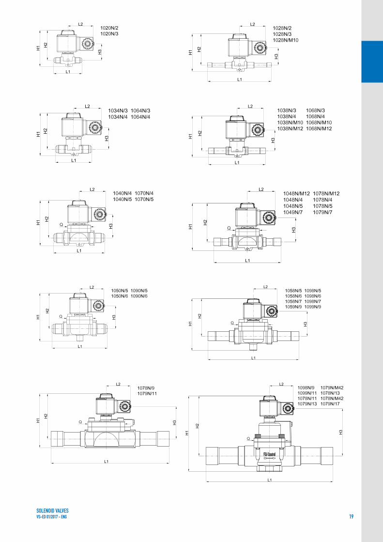
TABLE 7: Dimensions and weights of NC valves (high temperature) with 9300 coils (1)
Operating Principles
Catalogue Number
Dimensions [mm] Weight [g]H
1 H2 H3 L1 L2 Q
DirectActing
1020N/2#
75 62,5 34
58
52 –
340
1020N/3# 65 355
1028N/2# 125 350
1028N/2#.E 125 350
1028N/3# 125 365
1028N/M10# 125 365
DiaphragmPilot Operated
1064N/3#
82 69,5 40
68
52
–
400
1064N/4# 72 415
1068N/3# 111 400
1068N/M10# 111 395
1068N/M12# 127 420
1068N/4# 127 420
1070N/4#
91 75 47
100
45
710
1070N/5# 106 755
1078N/M12# 127 690
1078N/4# 127 680
1078N/5# 175 775
1079N/7# 190 765
1090N/5#
106 78 50
120
57
1035
1090N/6# 124 1365
1098N/5# 175 995
1098N/6# 175 1185
1098N/7# 180 1170
1099N/9# 216 1225
1078N/9#115 96 72
25080
2565
1079N/11# 292 2620
Piston Pilot Operated
1034N/3#
92,5 80 50,5
68
52
–
440
1034N/4# 72 457
1038N/3# 111 440
1038N/M10# 111 435
1038N/M12# 127 462
1038N/4# 127 462
1040N/4#
100,5 84,5 56,5
100
45
781
1040N/5# 106 831
1048N/M12# 127 759
1048N/4# 127 748
1048N/5# 175 853
1049N/7# 190 842
1050N/5#
121 93 65
120
57
1157
1050N/6# 124 1487
1058N/5# 175 1117
1058N/6# 175 1307
1058N/7# 180 1292
1059N/9# 216 1347
1098N/9#157 127 99
23560
2050
1099N/11# 277 2130
1078N/11#
175 141 113 278 68
2710
1079N/13# 2750
1079N/M42# 2750
1078N/13#
190 153 125 280 88
3810
1078N/M42# 3810
1079N/17# 3880
# = S , A6(1) : With coil 9320 the dimension L2 is equal to 65 mm and theweights must be increased of 500 g.
Connectors are not included in the boxes and have to be ordered separately

SOLENOID VALVESVS-ED 01/2017 - ENG 21
TABLE 8: Refrigerant flow capacity of NC valves (high temperature) [kW]
Operating Principles
Catalogue Number
Liquid line
R134a R32 R404A R407C R410A R507 R1234yf R1234ze R448A R449A R450A R452A
DirectActing
1020N/2# 2,98 4,40 2,08 3,02 3,00 2,01 2,20 2,63 2,74 2,75 2,78 2,12
1020N/3# 3,91 5,78 2,74 3,96 3,95 2,65 2,89 3,46 3,60 3,62 3,66 2,79
1028N/2# 2,55 3,77 1,79 2,58 2,58 1,73 1,89 2,26 2,35 2,36 2,39 1,82
1028N/2#.E
3,91 5,78 2,74 3,96 3,95 2,65 2,89 3,46 3,60 3,62 3,66 2,791028N/3#
1028N/M10#
DiaphragmPilot
Operated
1064N/3#
13,6 20,1 9,5 13,8 13,7 9,2 10,1 12,0 12,5 12,6 12,7 9,7
1064N/4#
1068N/3#
1068N/M10#
1068N/M12#
1068N/4#
1070N/4# 37,4 55,3 26,2 37,9 37,8 25,3 27,7 33,1 34,4 34,6 35,0 26,7
1070N/5# 44,4 65,6 31,1 45,0 44,8 30,0 32,8 39,3 40,8 41,0 41,5 31,7
1078N/M12#37,4 55,3 26,2 37,9 37,8 25,3 27,7 33,1 34,4 34,6 35,0 26,7
1078N/4#
1078N/5#44,4 65,6 31,1 45,0 44,8 30,0 32,8 39,3 40,8 41,0 41,5 31,7
1079N/7#
1090N/5# 64,6 95,5 45,2 65,5 65,2 43,7 47,8 57,2 59,5 59,7 60,5 46,1
1090N/6# 81,6 120,6 57,1 82,7 82,4 55,2 60,4 72,2 75,1 75,5 76,4 58,2
1098N/5# 64,6 95,5 45,2 65,5 65,2 43,7 47,8 57,2 59,5 59,7 60,5 46,1
1098N/6# 81,6 120,6 57,1 82,7 82,4 55,2 60,4 72,2 75,1 75,5 76,4 58,2
1098N/7#96,9 143,2 67,8 98,2 97,9 65,6 71,7 85,7 89,2 89,6 90,7 69,1
1099N/9#
1078N/9#170,0 251,3 119,0 172,3 171,7 115,0 125,8 150,4 156,5 157,2 159,1 121,3
1079N/11#
Piston Pilot
Operated
1034N/3#
17,0 25,1 11,9 17,2 17,2 11,5 12,6 15,0 15,7 15,7 15,9 12,1
1034N/4#
1038N/3#
1038N/M10#
1038N/M12#
1038N/4#
1040N/4# 40,8 60,3 28,6 41,4 41,2 27,6 30,2 36,1 37,6 37,7 38,2 29,1
1040N/5# 51,0 75,4 35,7 51,7 51,5 34,5 37,7 45,1 47,0 47,2 47,7 36,4
1048N/M12#40,8 60,3 28,6 41,4 41,2 27,6 30,2 36,1 37,6 37,7 38,2 29,1
1048N/4#
1048N/5#51,0 75,4 35,7 51,7 51,5 34,5 37,7 45,1 47,0 47,2 47,7 36,4
1049N/7#
1050N/5# 64,6 95,5 45,2 65,5 65,2 43,7 47,8 57,2 59,5 59,7 60,5 46,1
1050N/6# 81,6 120,6 57,1 82,7 82,4 55,2 60,4 72,2 75,1 75,5 76,4 58,2
1058N/5# 64,6 95,5 45,2 65,5 65,2 43,7 47,8 57,2 59,5 59,7 60,5 46,1
1058N/6# 81,6 120,6 57,1 82,7 82,4 55,2 60,4 72,2 75,1 75,5 76,4 58,2
1058N/7#96,9 143,2 67,8 98,2 97,9 65,6 71,7 85,7 89,2 89,6 90,7 69,1
1059N/9#
1098N/9#170,0 251,3 119,0 172,3 171,7 115,0 125,8 150,4 156,5 157,2 159,1 121,3
1099N/11#
1078N/11#
272,0 - 190,4 275,7 274,7 184,0 - 240,6 250,4 251,5 254,6 194,11079N/13#
1079N/M42#
1078N/13#
425,0 - 297,5 430,8 429,3 287,5 - 376,0 391,3 393,0 397,8 303,31078N/M42#
1079N/17#
# = S , A6 Continued
Standard rating conditions according to AHRI Standard 760-2007Temperature leaving evaporator 50 °F (9,9 °C)
Condensing temperature 110 °F (43,3 °C) Evaporator superheating 10 °R (5,5 °K)Liquid temperature 100 °F (37,8 °C) Suction line temperature 65 °F (18,3 °C)Subcooling 10 °R (5,5 °K) Suction superheating 15 °R (8,4 °K)Evaporating temperature 40 °F (4,4 °C) Discharge temperature 160 °F (71,1 °C)

SOLENOID VALVESVS-ED 01/2017 - ENG22
TABLE 8: Refrigerant flow capacity of NC valves (high temperature) [kW]
Operating Principles
Catalogue Number
Suction line
R134a R32 R404A R407C R410A R507 R1234yf R1234ze R448A R449A R450A R452A
DirectActing
1020N/2#
– – – – – – – – – – – –
1020N/3#
1028N/2#
1028N/2#.E
1028N/3#
1028N/M10#
DiaphragmPilot
Operated
1064N/3#
1,46 3,40 1,76 1,82 2,64 1,78 1,18 1,14 1,92 1,76 1,27 1,69
1064N/4#
1068N/3#
1068N/M10#
1068N/M12#
1068N/4#
1070N/4# 4,00 9,35 4,84 4,99 7,26 4,91 3,23 3,12 5,28 4,84 3,50 4,64
1070N/5# 4,75 11,09 5,74 5,92 8,61 5,82 3,84 3,71 6,26 5,74 4,15 5,51
1078N/M12#4,00 9,35 4,84 4,99 7,26 4,91 3,23 3,12 5,28 4,84 3,50 4,64
1078N/4#
1078N/5#4,75 11,09 5,74 5,92 8,61 5,82 3,84 3,71 6,26 5,74 4,15 5,51
1079N/7#
1090N/5# 6,9 16,2 8,4 8,6 12,5 8,5 5,6 5,4 9,1 8,4 6,0 8,0
1090N/6# 8,7 20,4 10,6 10,9 15,8 10,7 7,1 6,8 11,5 10,6 7,6 10,1
1098N/5# 6,9 16,2 8,4 8,6 12,5 8,5 5,6 5,4 9,1 8,4 6,0 8,0
1098N/6# 8,7 20,4 10,6 10,9 15,8 10,7 7,1 6,8 11,5 10,6 7,6 10,1
1098N/7#10,4 24,2 12,5 12,9 18,8 12,7 8,4 8,1 13,7 12,5 9,1 12,0
1099N/9#
1078N/9#18,2 42,5 22,0 22,7 33,0 22,3 14,7 14,2 24,0 22,0 15,9 21,1
1079N/11#
Piston Pilot
Operated
1034N/3#
1,82 4,25 2,20 2,27 3,30 2,23 1,47 1,42 2,40 2,20 1,59 2,11
1034N/4#
1038N/3#
1038N/M10#
1038N/M12#
1038N/4#
1040N/4# 4,37 10,20 5,28 5,45 7,92 5,35 3,53 3,41 5,76 5,28 3,82 5,06
1040N/5# 5,46 12,75 6,60 6,81 9,90 6,69 4,41 4,26 7,20 6,60 4,77 6,33
1048N/M12#4,37 10,20 5,28 5,45 7,92 5,35 3,53 3,41 5,76 5,28 3,82 5,06
1048N/4#
1048N/5#5,46 12,75 6,60 6,81 9,90 6,69 4,41 4,26 7,20 6,60 4,77 6,33
1049N/7#
1050N/5# 6,9 16,2 8,4 8,6 12,5 8,5 5,6 5,4 9,1 8,4 6,0 8,0
1050N/6# 8,7 20,4 10,6 10,9 15,8 10,7 7,1 6,8 11,5 10,6 7,6 10,1
1058N/5# 6,9 16,2 8,4 8,6 12,5 8,5 5,6 5,4 9,1 8,4 6,0 8,0
1058N/6# 8,7 20,4 10,6 10,9 15,8 10,7 7,1 6,8 11,5 10,6 7,6 10,1
1058N/7#10,4 24,2 12,5 12,9 18,8 12,7 8,4 8,1 13,7 12,5 9,1 12,0
1059N/9#
1098N/9#18,2 42,5 22,0 22,7 33,0 22,3 14,7 14,2 24,0 22,0 15,9 21,1
1099N/11#
1078N/11#
29,1 - 35,2 36,3 52,8 35,7 - 22,7 38,4 35,2 25,4 33,81079N/13#
1079N/M42#
1078N/13#
45,5 - 55,0 56,8 82,5 55,8 - 35,5 60,0 55,0 39,8 52,81078N/M42#
1079N/17#
# = S , A6 Continued
Standard rating conditions according to AHRI Standard 760-2007Temperature leaving evaporator 50 °F (9,9 °C)
Condensing temperature 110 °F (43,3 °C) Evaporator superheating 10 °R (5,5 °K)Liquid temperature 100 °F (37,8 °C) Suction line temperature 65 °F (18,3 °C)Subcooling 10 °R (5,5 °K) Suction superheating 15 °R (8,4 °K)Evaporating temperature 40 °F (4,4 °C) Discharge temperature 160 °F (71,1 °C)

SOLENOID VALVESVS-ED 01/2017 - ENG 23
TABLE 8: Refrigerant flow capacity of NC valves (high temperature) [kW]
Operating Principles
Catalogue Number
Hot Gas line
R134a R32 R404A R407C R410A R507 R1234yf R1234ze R448A R449A R450A R452A
DirectActing
1020N/2# 1,49 3,18 1,68 2,08 2,38 1,67 1,16 1,20 2,07 1,89 1,34 1,75
1020N/3# 1,96 4,18 2,21 2,74 3,13 2,19 1,53 1,58 2,71 2,48 1,76 2,30
1028N/2# 1,28 2,72 1,44 1,79 2,04 1,43 1,00 1,03 1,77 1,62 1,15 1,50
1028N/2#.E
1,96 4,18 2,21 2,74 3,13 2,19 1,53 1,58 2,71 2,48 1,76 2,301028N/3#
1028N/M10#
DiaphragmPilot
Operated
1064N/3#
6,8 14,5 7,7 9,5 10,9 7,6 5,3 5,5 9,4 8,6 6,1 8,0
1064N/4#
1068N/3#
1068N/M10#
1068N/M12#
1068N/4#
1070N/4# 18,7 40,0 21,1 26,2 29,9 21,0 14,6 15,1 26,0 23,7 16,8 22,0
1070N/5# 22,2 47,4 25,1 31,1 35,5 24,9 17,3 17,9 30,8 28,1 20,0 26,0
1078N/M12#18,7 40,0 21,1 26,2 29,9 21,0 14,6 15,1 26,0 23,7 16,8 22,0
1078N/4#
1078N/5#22,2 47,4 25,1 31,1 35,5 24,9 17,3 17,9 30,8 28,1 20,0 26,0
1079N/7#
1090N/5# 32,3 69,0 36,5 45,2 51,7 36,3 25,2 26,0 44,8 41,0 29,1 37,9
1090N/6# 40,8 87,2 46,1 57,1 65,3 45,8 31,9 32,9 56,6 51,7 36,7 47,9
1098N/5# 32,3 69,0 36,5 45,2 51,7 36,3 25,2 26,0 44,8 41,0 29,1 37,9
1098N/6# 40,8 87,2 46,1 57,1 65,3 45,8 31,9 32,9 56,6 51,7 36,7 47,9
1098N/7#48,5 103,5 54,7 67,8 77,5 54,4 37,8 39,0 67,3 61,4 43,6 56,9
1099N/9#
1078N/9#85,0 181,6 96,0 119,0 136,0 95,4 66,4 68,5 118,0 107,8 76,5 99,8
1079N/11#
Piston Pilot
Operated
1034N/3#
8,5 18,2 9,6 11,9 13,6 9,5 6,6 6,9 11,8 10,8 7,7 10,0
1034N/4#
1038N/3#
1038N/M10#
1038N/M12#
1038N/4#
1040N/4# 20,4 43,6 23,0 28,6 32,6 22,9 15,9 16,4 28,3 25,9 18,4 24,0
1040N/5# 25,5 54,5 28,8 35,7 40,8 28,6 19,9 20,6 35,4 32,3 23,0 29,9
1048N/M12#20,4 43,6 23,0 28,6 32,6 22,9 15,9 16,4 28,3 25,9 18,4 24,0
1048N/4#
1048N/5#25,5 54,5 28,8 35,7 40,8 28,6 19,9 20,6 35,4 32,3 23,0 29,9
1049N/7#
1050N/5# 32,3 69,0 36,5 45,2 51,7 36,3 25,2 26,0 44,8 41,0 29,1 37,9
1050N/6# 40,8 87,2 46,1 57,1 65,3 45,8 31,9 32,9 56,6 51,7 36,7 47,9
1058N/5# 32,3 69,0 36,5 45,2 51,7 36,3 25,2 26,0 44,8 41,0 29,1 37,9
1058N/6# 40,8 87,2 46,1 57,1 65,3 45,8 31,9 32,9 56,6 51,7 36,7 47,9
1058N/7#48,5 103,5 54,7 67,8 77,5 54,4 37,8 39,0 67,3 61,4 43,6 56,9
1059N/9#
1098N/9#85,0 181,6 96,0 119,0 136,0 95,4 66,4 68,5 118,0 107,8 76,5 99,8
1099N/11#
1078N/11#
136,0 - 153,6 190,4 217,6 152,6 - 109,6 188,8 172,5 122,4 159,71079N/13#
1079N/M42#
1078N/13#
212,5 - 240,0 297,5 340,0 238,5 - 171,3 295,0 269,5 191,3 249,51078N/M42#
1079N/17#
# = S , A6
Standard rating conditions according to AHRI Standard 760-2007Temperature leaving evaporator 50 °F (9,9 °C)
Condensing temperature 110 °F (43,3 °C) Evaporator superheating 10 °R (5,5 °K)Liquid temperature 100 °F (37,8 °C) Suction line temperature 65 °F (18,3 °C)Subcooling 10 °R (5,5 °K) Suction superheating 15 °R (8,4 °K)Evaporating temperature 40 °F (4,4 °C) Discharge temperature 160 °F (71,1 °C)

SOLENOID VALVESVS-ED 01/2017 - ENG24
All the valves are exclusively sold in the model without coil (suffix S). These valves can be coupled with the coils in series 9100, 9110, 9120, 9160, 9300, and 9320.
The valves series 1328N are direct acting valves. Their operation depends only on the magnetic field produced by the current flow into the coil. Opening/closing of main valve seat, the only seat, is directly controlled by the mobile plunger.These valves can work with zero pressure differential.
The valves in series 1338N are pilot-operated piston solenoid valves. Their operation depends not only on the magnetic field produced by the current flow into the coil, but also on a minimum inlet pressure, which is necessary to:• open the piston and keep it lifted off the main opening• close the piston and ensure the tightness on the main
openingOpening/closing of main valve seat is controlled by the piston, while opening/closing of pilot seat is controlled by the mobile plunger of the coil.These valves cannot work with zero differential pressure.
CONSTRUCTIONThe NC pulse solenoid valves are equipped with a specific reinforced magnetic unit (mobile plunger + valve sleeve for holding it), specifically designed to guarantee a very high number of work cycles compared to a normal NC solenoid valve.The main parts of the solenoid valves described in this chapter are constructed with the following materials:• Hot forged brass EN 12420 – CW 617N for body and cover• Copper tube EN 12735-1 – Cu-DHP for solder connections
APPLICATIONThe solenoid valves illustrated in this chapter are designed for applications that require a solenoid valve that cycles at high frequencies for a short period, to accurately maintain the regulated temperature of the refrigeration fluid. They can be installed on systems that use the following refrigerant fluids:• HFC (R134a , R404A , R407C , R410A , 507)• HFO and HFO/HFC mixtures (R1234ze , R448A , R449A ,
R450A , and R452A)belonging to Group 2, as defined in Article 13, Chapter 1, Point (b) of Directive 2014/68/EU, with reference to EC Regulation No. 1272/2008.Furthermore, the same solenoid valves can also be installed on systems that use the following refrigeration fluids:• HFC (R32)• HFO (R1234yf)classified as A2L in the ASHRAE 34-2013 standard, and belonging to Group 1, as defined in Article 13, Chapter 1, Point (a) of Directive 2014/68/EU, with reference to EC Regulation No. 1272/2008.For specific applications with refrigerant fluids not listed above, please contact Castel Technical Department.CAUTION!: The pulse solenoid valves in this chapter cannot be used with R22, mineral oils, or alkylbenzene oils.
OPERATIONThe valves listed in this chapter are normally closed valves (NC). This means that when the coil is not energised, the plunger closes the fluid flow. When the coil is energised, the plunger opens the valve seat connecting the inlet to the outlet.
CHAPTER 3NORMALLY-CLOSED PULSE SOLENOID VALVES
FOR REFRIGERATION PLANTS THAT USE HFC OR HFO REFRIGERANTS

SOLENOID VALVESVS-ED 01/2017 - ENG 25
• Hot forged brass EN 12420 – CW 724R for mobile plunger valve sleeve
• Ferritic stainless steel EN 10088-3 – 1.4105 for the fixed and mobile plungers
• Hydrogenated nitrile butadiene rubber (HNBR) for outlet seal gaskets
• P.T.F.E. for seat gaskets
INSTALLATIONThe valve series 1328N and 1338N can be used as either a hot gas by-pass valve between the high and the low pressure sides of a system or as a liquid injection valve, within the limits of use indicated in TABLE 9 and the capacities indicated in TABLE 11.TABLE 9 shows the following functional characteristics of a solenoid valve:• Connection dimensions• PS: maximum allowable pressure of the refrigerant• TS: maximum / minimum allowable temperature of the
refrigerant• TA: maximum / minimum allowable ambient temperature• Kv: discharge factor• minOPD: minimum Opening Pressure Differential. This
is the minimum pressure differential between inlet and outlet at which a pilot-operated solenoid valve can open and stay opened or close and maintain the seal.
• MOPD: maximum Opening Pressure Differential according to AHRI STANDARD 760 : 2014. This is the maximum pressure differential between inlet and outlet at which a
solenoid valve can open.• No. of Cycles: useful operational life expected for the valve
expressed in the number of operating cycles, considering a complete cycle consisting of an opening and successive closing of the valve.
Before connecting the valve to the pipe, it is advisable to make sure that the refrigerating system is clean. In fact, valves with P.T.F.E. gaskets, and particularly piston valves, are sensitive to dirt and debris. Furthermore, check that the flow direction in the pipe corresponds to the arrow stamped on the valve body. All the valves can be mounted in any position so long as the coil does not point downwards. The brazing of valves with solder connections should be carried out with care, using a low melting point filler material. It is not necessary to disassemble the valves before brazing, but it is important to avoid direct contact between the torch flame and the valve body, which could be damaged and compromise the proper functioning of the valve.Before connecting a valve to the electrical system, be sure that the line voltage and frequency correspond to the values marked on the coil.
TRACEABILITYThe direct action valves in series 1328N and the pilot-operated solenoid valves in series 1338N are identified by a plastic label fit on the valve enclosure of the mobile plunger. This label includes the following data: valve code, refrigerants, PS, TS, and production lot.
TABLE 9: General Characteristics of NC pulse valves with ODS connections
Operating Principles
Catalogue Number
Connections ODS
Seat
size
nomi-
nal Ø
[mm]
Kv
Factor
[m3/h]
Opening Pressure Differential[bar]
PS[bar]
TS [°C] TA [°C]
CyclesNomin
Risk Category according
to PED Recast
Ø
[in.]
Ø
[mm]
min
OPD
MOPD
min. max.min.(2)
max.
coil series
910091109300(AC)
9160(AC)
91209320(AC)
91209320(DC)
DirectActing
1328N/2S020 (1) 1/4" – 2,2 0,15 0 28 30 35 21
45 – 40 +150 – 40 +50 6.000.000 Art. 4.3
1328N/2S030 (1) 1/4" – 3 0,23 0 18 21 25 18
1328N/3S020 (1) 3/8" – 2,2 0,15 0 28 30 35 21
1328N/3S030 (1) 3/8" – 3 0,23 0 18 21 25 18
1328N/M13S020 (1) – 10 2,2 0,15 0 28 30 35 21
1328N/M13S030 (1) – 10 3 0,23 0 18 21 25 18
Piston Pilot
Operated
1338N/3S065 (1) 3/8" –
6,5 1,00 0,05 21 28 35 18 45 – 40 +150 – 40 +50 6.000.000 Art. 4.31338N/M10S065 (1) – 10
1338N/M12S065 (1) – 12
1338N/4S065 (1) 1/2" –
(1) NB: No use with R22, mineral and alchylbenzene oils(2) Check TAmin of the chosen coil

SOLENOID VALVESVS-ED 01/2017 - ENG26
(1) : With coil 9320 the dimension L2 is equal to 65 mm and theweights must be increased of 500 g.
Connectors are not included in the boxes and have to be ordered separately
TABLE 10: Dimensions and Weights of NC pulse valves with 9300 coils (1)
Operating Principles
Catalogue NumberDimensions [mm] Weight
[g]H1 H2 H3 L1 L2 Q
DirectActing
1328N/2S020 (1)
75 62,5 34 125 52 –
350
1328N/2S030 (1) 350
1328N/3S020 (1) 365
1328N/3S030 (1) 365
1328N/M13S020 (1) 365
1328N/M13S030 (1) 365
Piston Pilot Operated
1338N/3S065 (1)
92,5 80 50,5
111
52 –
440
1338N/M10S065 (1) 111 435
1338N/M12S065 (1) 127 462
1338N/4S065 (1) 127 462

SOLENOID VALVESVS-ED 01/2017 - ENG 27
TABLE 11: Refrigerant Flow Capacity of NC pulse valves [kW]
Operating Principles
Catalogue Number
Liquid line
R134a R32 R404A R407C R410A R507 R1234yf R1234ze R448A R449A R450A R452A
DirectActing
1328N/2S020 2,55 3,77 1,79 2,58 2,58 1,73 1,89 2,26 2,35 2,36 2,39 1,82
1328N/2S030 3,91 5,78 2,74 3,96 3,95 2,65 2,89 3,46 3,60 3,62 3,66 2,79
1328N/3S020 2,55 3,77 1,79 2,58 2,58 1,73 1,89 2,26 2,35 2,36 2,39 1,82
1328N/3S030 3,91 5,78 2,74 3,96 3,95 2,65 2,89 3,46 3,60 3,62 3,66 2,79
1328N/M13S020 2,55 3,77 1,79 2,58 2,58 1,73 1,89 2,26 2,35 2,36 2,39 1,82
1328N/M13S030 3,91 5,78 2,74 3,96 3,95 2,65 2,89 3,46 3,60 3,62 3,66 2,79
DiaphragmPilot
Operated
1338N/3S065
13,6 20,1 9,5 13,8 13,7 9,2 10,1 12,0 12,5 12,6 12,7 9,71338N/M10S065
1338N/M12S065
1338N/4S065
TABLE 11: Refrigerant Flow Capacity of NC pulse valves [kW]
Operating Principles
Catalogue Number
Hot Gas line
R134a R32 R404A R407C R410A R507 R1234yf R1234ze R448A R449A R450A R452A
DirectActing
1328N/2S020 1,28 2,72 1,44 1,79 2,04 1,43 1,00 1,03 1,77 1,62 1,15 1,50
1328N/2S030 1,96 4,18 2,21 2,74 3,13 2,19 1,53 1,58 2,71 2,48 1,76 2,30
1328N/3S020 1,28 2,72 1,44 1,79 2,04 1,43 1,00 1,03 1,77 1,62 1,15 1,50
1328N/3S030 1,96 4,18 2,21 2,74 3,13 2,19 1,53 1,58 2,71 2,48 1,76 2,30
1328N/M13S020 1,28 2,72 1,44 1,79 2,04 1,43 1,00 1,03 1,77 1,62 1,15 1,50
1328N/M13S030 1,96 4,18 2,21 2,74 3,13 2,19 1,53 1,58 2,71 2,48 1,76 2,30
DiaphragmPilot
Operated
1338N/3S065
6,8 14,5 7,7 9,5 10,9 7,6 5,3 5,5 9,4 8,6 6,1 8,01338N/M10S065
1338N/M12S065
1338N/4S065
# = S , A6
t
Standard rating conditions according to AHRI Standard 760-2007Temperature leaving evaporator 50 °F (9,9 °C)
Condensing temperature 110 °F (43,3 °C) Evaporator superheating 10 °R (5,5 °K)Liquid temperature 100 °F (37,8 °C) Suction line temperature 65 °F (18,3 °C)Subcooling 10 °R (5,5 °K) Suction superheating 15 °R (8,4 °K)Evaporating temperature 40 °F (4,4 °C) Discharge temperature 160 °F (71,1 °C)

SOLENOID VALVESVS-ED 01/2017 - ENG28
CHAPTER 4NORMALLY-OPEN SOLENOID VALVES
FOR REFRIGERATION PLANTS THAT USE HCFC, HFC OR HFO REFRIGERANTS
The valves series 1164 ; 1168 ; 1170 ; 1178 (excluded /11 , /13 , /M42) ; 1190 ; 1198 (excluded /9) are pilot-operated diaphragm valves. Their operation depends not only on the magnetic field produced by the current flow into the coil, but also on a minimum inlet pressure, which is necessary to:• open the diaphragm and keep it lifted off the main
opening• close the diaphragm and ensure the tightness on the
main openingOpening/closing of main valve seat is controlled by the diaphragm while opening/closing of pilot seat is controlled by the mobile plunger of the coil.These valves cannot work with zero differential pressure.
The valves series 1134 ; 1138 ; 1140 ; 1148 ; 1150 ; 1158 ; 1178 (/11 , /13 , /M42) ; 1198/9 are pilot operated piston valves. Their operation depends not only on the magnetic field produced by the current flow into the coil, but also on a minimum inlet pressure, which is necessary to:• open the piston and keep it lifted off the main opening• close the piston and ensure the tightness on the main
openingOpening/closing of main valve seat is controlled by the piston, while opening/closing of pilot seat is controlled by the mobile plunger of the coil.These valves cannot work with zero differential pressure.
CONSTRUCTIONThe main parts of the solenoid valves described in this chapter are constructed with the following materials:• Hot forged brass EN 12420 – CW 617N for body and
cover
APPLICATIONThe solenoid valves illustrated in this chapter are designed for installation on commercial refrigeration systems and on civil and industrial air conditioning plants that use the following refrigerant fluids:• HCFC (R22)• HFC (R134a , R404A , R407C , R410A , R507)• HFO and HFO/HFC mixtures (R1234ze , R448A , R449A
, R450A , and R452A)belonging to Group 2, as defined in Article 13, Chapter 1, Point (b) of Directive 2014/68/EU, with reference to EC Regulation No. 1272/2008.Furthermore, the same solenoid valves, up to DN 25, that is models 1178/9 and 1198/9, can also be installed on systems using the following refrigeration fluids:• HFC (R32)• HFO (R1234yf)classified as A2L in the ASHRAE 34-2013 standard, and belonging to Group 1, as defined in Article 13, Chapter 1, Point (a) of Directive 2014/68/EU, with reference to EC Regulation No. 1272/2008.For specific applications with refrigerant fluids not listed above, please contact Castel Technical Department.
OPERATIONThe valves listed in this chapter are normally open valves (NO). This means that when the coil is not energised, the plunger opens the fluid flow. When the coil is energized, the plunger closes the fluid flow.All the valves are exclusively sold in the model without coil (suffix S).N.B.: the NO valve visually differs from the corresponding NC model by means of a red ring installed below the yellow nut that fastens the coil.

SOLENOID VALVESVS-ED 01/2017 - ENG 29
• Copper tube EN 12735-1 – Cu-DHP for solder connections
• Austenitic stainless steel EN 10088-2 – 1.4303 for enclosure where the plunger moves
• Ferritic stainless steel EN 10088-3 – 1.4105 for the plunger
• Austenitic stainless steel EN ISO 3506 – A2-70 for tightening screws between body and cover.
• Chloroprene rubber (CR) for the outlet seal gaskets• P.T.F.E. for seat gaskets
INSTALLATIONThe valves can be installed on the three main branches of a plant (hot gas line, liquid line, and suction line), while respecting the limits of use indicated in TABLES 12 and 13 and the capacities indicated in TABLE 15. TABLES 12 and 13 show the following functional characteristics of a solenoid valve:• Connection dimensions• PS: maximum allowable pressure of the refrigerant• TS: maximum / minimum allowable temperature of the
refrigerant• TA: maximum / minimum allowable ambient
temperature• Kv: dicharge factor• minOPD: minimum Opening Pressure Differential. This
is the minimum pressure differential between inlet and outlet at which a pilot-operated solenoid valve can open and stay opened or close and maintain the seal.
• MOPD: maximum Opening Pressure Differential according to AHRI STANDARD 760 : 2014. This is the maximum pressure differential between inlet and outlet at which a solenoid valve can open.
Before connecting the valve to the pipe, it is advisable to make sure that the refrigerating system is clean. In fact, valves with P.T.F.E. gaskets, and particularly piston valves,
are sensitive to dirt and debris. Furthermore, check that the flow direction in the pipe corresponds to the arrow stamped on the valve body. All the valves can be mounted in any position so long as the coil does not point downwards. The brazing of valves with solder connections should be carried out with care, using a low melting point filler material. It is not necessary to disassemble the valves before brazing, but it is important to avoid direct contact between the torch flame and the valve body, which could be damaged and compromise the proper functioning of the valve.Before connecting a valve to the electrical system, be sure that the line voltage and frequency correspond to the values marked on the coil.
N.B. The NO valves have been designed to work only with direct current coils; therefore, they can be used solely with coils 9120/RD1 (HM3 type – 12 VDC) , 9120/RD2 (HM3 type – 24 VDC) , 9120/RD4 (HM3 type – 48 VDC). For applications with 220/230 VAC power supply, it is mandatory to couple the NO valves with the following components: Coil 9120/RD6 (HM3 types - 220 VRAC) + Connector/Rectifier 9150/R45 or 9150/R90.NO solenoid valves cannot be coupled with coils series 9100, 9110, 9120/RA6, 9160, 9300, and 9320.
TRACEABILITYPilot-operated diaphragm and piston valves series 1134, 1138, 1140, 1148, 1150, 1158, 1164, 1168, 1170, 1178, 1190, and 1198 are identified by marking on the yellow locking ring-nut for the coil. The marking on the ring-nut includes the following data: valve code, PS, and production lot.

SOLENOID VALVESVS-ED 01/2017 - ENG30
(1) Temperature peaks of 120 °C are allowed during defrosting(2) Temperature peaks of 130 °C are allowed during defrosting(3) Check TAmin of the chosen coil
(1) Temperature peaks of 120 °C are allowed during defrosting(2) Temperature peaks of 130 °C are allowed during defrosting(3) Check TAmin of the chosen coil
TABLE 12: General characteristics of NO valves with SAE Flare connections
Operating Principles
Catalogue Number
SAE
Flare
Connections
Seat
size
nominal
Ø
[mm]
Kv
Factor
[m3/h]
Opening Pressure Differential[bar]
PS[bar]
TS [°C] TA [°C] Risk Category according
to PED Recast
min OPD
MOPD9120/RD6
MOPD 9120/RD19120/RD2
min. max.min.(3)
max.
DiaphragmPilot
Operated
1164/3S 3/8" 6,5 0,80
0,05
30 16
45 – 35+105
(1)– 35 +50 Art. 4.3
1170/4S 1/2"12,5
2,20
30 301170/5S 5/8" 2,61
1190/5S 5/8"16,5
3,80
1190/6S 3/4" 4,80
Piston Pilot
Operated
1134/3S 3/8" 6,5 1,00 0,05
30 30 45 – 35+110
(2)– 35 +50 Art. 4.3
1140/4S 1/2"12,5
2,40
0,071140/5S 5/8" 3,00
1150/5S 5/8"16,5
3,80
1150/6S 3/4" 4,80
TABLE 13: General characteristics of NO valves with ODS connections
Operating Principles
Catalogue Number
Connections
ODSSeat
size
nominal
Ø
[mm]
Kv
Factor
[m3/h]
Opening Pressure Differential[bar]
PS[bar]
TS [°C] TA [°C] Risk Category according
to PED Recast
Ø[in.]
Ø[mm]
min OPD
MOPD9120/RD6
MOPD 9120/RD19120/RD2
min. max. min. max.
DiaphragmPilot
Operated
1168/3S 3/8" –6,5 0,80
0,05
30 16
45 – 35+105
(1)– 35 +50 Art. 4.3
1168/M10S – 10
1178/M12S – 12
12,50,80
30 30
1178/4S 1/2" –
1178/5S 5/8" 16 2,61
1198/5S 5/8" 16
16,5
3,80
1198/6S 3/4" – 4,80
1198/7S 7/8" 22 5,70
1178/9S 1.1/8" – 25,5 10 28 28
Piston Pilot
Operated
1138/3S 3/8" –6,5 1,00 0,05
30 30
45 – 35+110
(2)– 35 +50
Art. 4.3
1138/M10S – 10
1148/M12S – 12
12,52,40
0,07
1148/4S 1/2" –
1148/5S 5/8" 16 3,00
1158/5S 5/8" 16
16,5
3,80
1158/6S 3/4" – 4,80
1158/7S 7/8" 22 5,70
1198/9S 1.1/8" – 25 100,1
30 161178/11S 1.3/8" 35 27 16
1178/13S 1.5/8" –34 25 0,15 I
1178/M42S – 42

SOLENOID VALVESVS-ED 01/2017 - ENG 31
TABLE 14: Dimensions and weights of NO valves with 9120 coils
Operating Principles
Catalogue NumberDimensions [mm] Weight
[g]H1 H2 H3 L1 L2 Q
DiaphragmPilot Operated
1164/3S
87 74,5 40
68
65
–
705
1168/3S 111 705
1168/M10S 111 700
1170/4S
96 80 47
100
45
1015
1170/5S 106 1060
1178/M12S 127 995
1178/4S 127 985
1178/5S 175 1080
1190/5S
111 83 50
120
57
1340
1190/6S 124 1670
1198/5S 175 1300
1198/6S 175 1490
1198/7S 180 1475
1178/9S 120 101 72 250 80 2870
Piston Pilot Operated
1134/3S
97,5 85 50,5
68
65
–
775
1138/3S 111 775
1138/M11S 111 770
1140/4S
105,5 89,5 56,5
100
45
1117
1140/5S 106 1166
1148/M12S 127 1095
1148/4S 127 1084
1148/5S 175 1188
1150/5S
126 98 70
120
57
1462
1150/6S 124 1792
1158/5S 175 1422
1158/6S 175 1612
1158/7S 180 1597
1198/9S 162 132 99 235 60 2355
1178/11S 180 146 113 278 68 3015
1178/13S195 158 130 280 88
3820
1178/M42S 3820
Connectors are not included in the boxes and have to be ordered separately

SOLENOID VALVESVS-ED 01/2017 - ENG32

SOLENOID VALVESVS-ED 01/2017 - ENG 33
TABLE 15: Refrigerant flow capacity of NO valves [kW]
Operating Principles
Catalogue Number
Liquid line
R134a R22 R404A R407C R410A R507 R1234yf R1234ze R448A R449A R450A R452A
DiaphragmPilot
Operated
1064/3S
13,6 14,6 9,5 13,8 13,7 9,2 10,1 12,0 12,5 12,6 12,7 9,71068/3S
1068/M10S
1070/4S 37,4 40,3 26,2 37,9 37,8 25,3 27,7 33,1 34,4 34,6 35,0 26,7
1070/5S 44,4 47,8 31,1 45,0 44,8 30,0 32,8 39,3 40,8 41,0 41,5 31,7
1078/M12S37,4 40,3 26,2 37,9 37,8 25,3 27,7 33,1 34,4 34,6 35,0 26,7
1078/4S
1078/5S 44,4 47,8 31,1 45,0 44,8 30,0 32,8 39,3 40,8 41,0 41,5 31,7
1090/5S 64,6 69,5 45,2 65,5 65,2 43,7 47,8 57,2 59,5 59,7 60,5 46,1
1090/6S 81,6 87,8 57,1 82,7 82,4 55,2 60,4 72,2 75,1 75,5 76,4 58,2
1098/5S 64,6 69,5 45,2 65,5 65,2 43,7 47,8 57,2 59,5 59,7 60,5 46,1
1098/6S 81,6 87,8 57,1 82,7 82,4 55,2 60,4 72,2 75,1 75,5 76,4 58,2
1098/7S 96,9 104,3 67,8 98,2 97,9 65,6 71,7 85,7 89,2 89,6 90,7 69,1
1078/9S 170,0 183,0 119,0 172,3 171,7 115,0 125,8 150,4 156,5 157,2 159,1 121,3
Piston Pilot
Operated
1034/3S
17,0 18,3 11,9 17,2 17,2 11,5 12,6 15,0 15,7 15,7 15,9 12,11038/3S
1038/M10S
1040/4S 40,8 43,9 28,6 41,4 41,2 27,6 30,2 36,1 37,6 37,7 38,2 29,1
1040/5S 51,0 54,9 35,7 51,7 51,5 34,5 37,7 45,1 47,0 47,2 47,7 36,4
1048/M12S40,8 43,9 28,6 41,4 41,2 27,6 30,2 36,1 37,6 37,7 38,2 29,1
1048/4S
1048/5S 51,0 54,9 35,7 51,7 51,5 34,5 37,7 45,1 47,0 47,2 47,7 36,4
1050/5S 64,6 69,5 45,2 65,5 65,2 43,7 47,8 57,2 59,5 59,7 60,5 46,1
1050/6S 81,6 87,8 57,1 82,7 82,4 55,2 60,4 72,2 75,1 75,5 76,4 58,2
1058/5S 64,6 69,5 45,2 65,5 65,2 43,7 47,8 57,2 59,5 59,7 60,5 46,1
1058/6S 81,6 87,8 57,1 82,7 82,4 55,2 60,4 72,2 75,1 75,5 76,4 58,2
1058/7S 96,9 104,3 67,8 98,2 97,9 65,6 71,7 85,7 89,2 89,6 90,7 69,1
1098/9S 170,0 183,0 119,0 172,3 171,7 115,0 125,8 150,4 156,5 157,2 159,1 121,3
1078/11S 272,0 292,8 190,4 275,7 274,7 184,0 - 240,6 250,4 251,5 254,6 194,1
1078/13S425,0 457,5 297,5 430,8 429,3 287,5 - 376,0 391,3 393,0 397,8 303,3
1078/M42S
ContinuedStandard rating conditions according to AHRI Standard 760-2007Temperature leaving evaporator 50 °F (9,9 °C)
Condensing temperature 110 °F (43,3 °C) Evaporator superheating 10 °R (5,5 °K)Liquid temperature 100 °F (37,8 °C) Suction line temperature 65 °F (18,3 °C)Subcooling 10 °R (5,5 °K) Suction superheating 15 °R (8,4 °K)Evaporating temperature 40 °F (4,4 °C) Discharge temperature 160 °F (71,1 °C)

SOLENOID VALVESVS-ED 01/2017 - ENG34
TABLE 15: Refrigerant flow capacity of NO valves [kW]
Operating Principles
Catalogue Number
Suction line
R134a R22 R404A R407C R410A R507 R1234yf R1234ze R448A R449A R450A R452A
DiaphragmPilot
Operated
1064/3S
1,46 2,04 1,76 1,82 2,64 1,78 1,18 1,14 1,92 1,76 1,27 1,691068/3S
1068/M10S
1070/4S 4,00 5,61 4,84 4,99 7,26 4,91 3,23 3,12 5,28 4,84 3,50 4,64
1070/5S 4,75 6,66 5,74 5,92 8,61 5,82 3,84 3,71 6,26 5,74 4,15 5,51
1078/M12S4,00 5,61 4,84 4,99 7,26 4,91 3,23 3,12 5,28 4,84 3,50 4,64
1078/4S
1078/5S 4,75 6,66 5,74 5,92 8,61 5,82 3,84 3,71 6,26 5,74 4,15 5,51
1090/5S 6,9 9,7 8,4 8,6 12,5 8,5 5,6 5,4 9,1 8,4 6,0 8,0
1090/6S 8,7 12,2 10,6 10,9 15,8 10,7 7,1 6,8 11,5 10,6 7,6 10,1
1098/5S 6,9 9,7 8,4 8,6 12,5 8,5 5,6 5,4 9,1 8,4 6,0 8,0
1098/6S 8,7 12,2 10,6 10,9 15,8 10,7 7,1 6,8 11,5 10,6 7,6 10,1
1098/7S 10,4 14,5 12,5 12,9 18,8 12,7 8,4 8,1 13,7 12,5 9,1 12,0
1078/9S 18,2 25,5 22,0 22,7 33,0 22,3 14,7 14,2 24,0 22,0 15,9 21,1
Piston Pilot
Operated
1034/3S
1,82 2,55 2,20 2,27 3,30 2,23 1,47 1,42 2,40 2,20 1,59 2,111038/3S
1038/M10S
1040/4S 4,37 6,12 5,28 5,45 7,92 5,35 3,53 3,41 5,76 5,28 3,82 5,06
1040/5S 5,46 7,65 6,60 6,81 9,90 6,69 4,41 4,26 7,20 6,60 4,77 6,33
1048/M12S4,37 6,12 5,28 5,45 7,92 5,35 3,53 3,41 5,76 5,28 3,82 5,06
1048/4S
1048/5S 5,46 7,65 6,60 6,81 9,90 6,69 4,41 4,26 7,20 6,60 4,77 6,33
1050/5S 6,9 9,7 8,4 8,6 12,5 8,5 5,6 5,4 9,1 8,4 6,0 8,0
1050/6S 8,7 12,2 10,6 10,9 15,8 10,7 7,1 6,8 11,5 10,6 7,6 10,1
1058/5S 6,9 9,7 8,4 8,6 12,5 8,5 5,6 5,4 9,1 8,4 6,0 8,0
1058/6S 8,7 12,2 10,6 10,9 15,8 10,7 7,1 6,8 11,5 10,6 7,6 10,1
1058/7S 10,4 14,5 12,5 12,9 18,8 12,7 8,4 8,1 13,7 12,5 9,1 12,0
1098/9S 18,2 25,5 22,0 22,7 33,0 22,3 14,7 14,2 24,0 22,0 15,9 21,1
1078/11S 29,1 40,8 35,2 36,3 52,8 35,7 - 22,7 38,4 35,2 25,4 33,8
1078/13S45,5 63,8 55,0 56,8 82,5 55,8 - 35,5 60,0 55,0 39,8 52,8
1078/M42S
ContinuedStandard rating conditions according to AHRI Standard 760-2007Temperature leaving evaporator 50 °F (9,9 °C)
Condensing temperature 110 °F (43,3 °C) Evaporator superheating 10 °R (5,5 °K)Liquid temperature 100 °F (37,8 °C) Suction line temperature 65 °F (18,3 °C)Subcooling 10 °R (5,5 °K) Suction superheating 15 °R (8,4 °K)Evaporating temperature 40 °F (4,4 °C) Discharge temperature 160 °F (71,1 °C)

SOLENOID VALVESVS-ED 01/2017 - ENG 35
TABLE 15: Refrigerant flow capacity of NO valves [kW]
Operating Principles
Catalogue Number
Hot Gas line
R134a R22 R404A R407C R410A R507 R1234yf R1234ze R448A R449A R450A R452A
DiaphragmPilot
Operated
1064/3S
6,8 9,0 7,7 9,5 10,9 7,6 5,3 5,5 9,4 8,6 6,1 8,01068/3S
1068/M10S
1070/4S 18,7 24,6 21,1 26,2 29,9 21,0 14,6 15,1 26,0 23,7 16,8 22,0
1070/5S 22,2 29,2 25,1 31,1 35,5 24,9 17,3 17,9 30,8 28,1 20,0 26,0
1078/M12S18,7 24,6 21,1 26,2 29,9 21,0 14,6 15,1 26,0 23,7 16,8 22,0
1078/4S
1078/5S 22,2 29,2 25,1 31,1 35,5 24,9 17,3 17,9 30,8 28,1 20,0 26,0
1090/5S 32,3 42,6 36,5 45,2 51,7 36,3 25,2 26,0 44,8 41,0 29,1 37,9
1090/6S 40,8 53,8 46,1 57,1 65,3 45,8 31,9 32,9 56,6 51,7 36,7 47,9
1098/5S 32,3 42,6 36,5 45,2 51,7 36,3 25,2 26,0 44,8 41,0 29,1 37,9
1098/6S 40,8 53,8 46,1 57,1 65,3 45,8 31,9 32,9 56,6 51,7 36,7 47,9
1098/7S 48,5 63,8 54,7 67,8 77,5 54,4 37,8 39,0 67,3 61,4 43,6 56,9
1078/9S 85,0 112,0 96,0 119,0 136,0 95,4 66,4 68,5 118,0 107,8 76,5 99,8
Piston Pilot
Operated
1034/3S
8,5 11,2 9,6 11,9 13,6 9,5 6,6 6,9 11,8 10,8 7,7 10,01038/3S
1038/M10S
1040/4S 20,4 26,9 23,0 28,6 32,6 22,9 15,9 16,4 28,3 25,9 18,4 24,0
1040/5S 25,5 33,6 28,8 35,7 40,8 28,6 19,9 20,6 35,4 32,3 23,0 29,9
1048/M12S20,4 26,9 23,0 28,6 32,6 22,9 15,9 16,4 28,3 25,9 18,4 24,0
1048/4S
1048/5S 25,5 33,6 28,8 35,7 40,8 28,6 19,9 20,6 35,4 32,3 23,0 29,9
1050/5S 32,3 42,6 36,5 45,2 51,7 36,3 25,2 26,0 44,8 41,0 29,1 37,9
1050/6S 40,8 53,8 46,1 57,1 65,3 45,8 31,9 32,9 56,6 51,7 36,7 47,9
1058/5S 32,3 42,6 36,5 45,2 51,7 36,3 25,2 26,0 44,8 41,0 29,1 37,9
1058/6S 40,8 53,8 46,1 57,1 65,3 45,8 31,9 32,9 56,6 51,7 36,7 47,9
1058/7S 48,5 63,8 54,7 67,8 77,5 54,4 37,8 39,0 67,3 61,4 43,6 56,9
1098/9S 85,0 112,0 96,0 119,0 136,0 95,4 66,4 68,5 118,0 107,8 76,5 99,8
1078/11S 136,0 179,2 153,6 190,4 217,6 152,6 - 109,6 188,8 172,5 122,4 159,7
1078/13S212,5 280,0 240,0 297,5 340,0 238,5 - 171,3 295,0 269,5 191,3 249,5
1078/M42S
Standard rating conditions according to AHRI Standard 760-2007Temperature leaving evaporator 50 °F (9,9 °C)
Condensing temperature 110 °F (43,3 °C) Evaporator superheating 10 °R (5,5 °K)Liquid temperature 100 °F (37,8 °C) Suction line temperature 65 °F (18,3 °C)Subcooling 10 °R (5,5 °K) Suction superheating 15 °R (8,4 °K)Evaporating temperature 40 °F (4,4 °C) Discharge temperature 160 °F (71,1 °C)

SOLENOID VALVESVS-ED 01/2017 - ENG36
CHAPTER 5NORMALLY-CLOSED SOLENOID VALVES
FOR REFRIGERATION PLANTS THAT USE HC REFRIGERANTS
type HF2 - “FAST LOCK” coils (A6 suffix with coil 9300/RA6-220/230 VAC).
All valves with an “EX” suffix are sold only in the version with coil series 9100EX (A6 suffix with coil, 9100EX-220/230 VAC, ATEX certified).
The valves series 1028N and 1028EX are direct acting valves. Their operation depends only on the magnetic field produced by the current flow into the coil. Opening/closing of main valve seat, the only seat, is directly controlled by the mobile plunger.These valves can work with zero pressure differential.
Valves 1068N, 1068EX, 1078N, 1078EX, 1079N, 1079EX, 1098N/7, 1098EX/7, 1099N/9, and 1099EX/9 are pilot-operated diaphragm solenoid valves. Their operation depends not only on the magnetic field produced by the current flow into the coil, but also on a minimum inlet pressure, which is necessary to:• open the diaphragm and keep it lifted off the main
opening• close the diaphragm and ensure the tightness on the
main openingOpening/closing of main valve seat is controlled by the diaphragm while opening/closing of pilot seat is controlled by the mobile plunger of the coil.These valves cannot work with zero differential pressure.
The valves 1098N/9, 1098EX/9, 1099N/11, and 1099EX/11 are pilot-operated piston solenoid valves. Their operation depends not only on the magnetic field produced by the current flow into the coil, but also on a minimum inlet pressure, which is necessary to:
APPLICATIONThe solenoid valves illustrated in this chapter have been developed by Castel for all those refrigeration applications that use the following HC refrigeration fluids: R290, R600, R600a, belonging to Group 1, defined in Article 13, Chapter 1, Point (a) of Directive 2014/68/EU, with reference to EC Regulation No. 1272/2008.
The solenoid valves with an “N” suffix (1028N, 1068N, 1078N, 1079N, 1098N, 1099N) must be employed only in refrigeration systems located in areas not classified as at risk of explosion, according to the definition in Annex I of Directive 1999/92/EC.
The solenoid valves with an “Ex” suffix (1028Ex, 1068Ex, 1078Ex, 1079Ex, 1098Ex, 1099Ex) comply with the European Standard EN 13463-1:2009 and, therefore, comply with the ESR of Directive 2014/34/EU – ATEx. This equipment is suitable for use on refrigeration systems located in areas classified as “Zone 2” risk of explosion, according to the definition in Annex I of Directive 1999/92/EC.
CAUTION!: The solenoid valves in this chapter cannot be used with mineral oils or alkylbenzene oils.
OPERATIONThe valves listed in this chapter are normally closed valves (NC). This means that when the coil is not energised, the plunger closes the fluid flow. When the coil is energised, the plunger opens the valve seat connecting the inlet to the outlet.
All valves with an “N” suffix are sold in the version without coil (with the S suffix), and in the version with series 9300,

SOLENOID VALVESVS-ED 01/2017 - ENG 37
• open the piston and keep it lifted off the main opening• close the piston and ensure the tightness on the main
openingOpening/closing of main valve seat is controlled by the piston, while opening/closing of pilot seat is controlled by the mobile plunger of the coil.These valves cannot work with zero differential pressure.
CONSTRUCTIONThe main parts of the valves are constructed with the following materials:• Hot forged brass EN 12420 – CW 617N for body and
cover• Copper tube EN 12735-1 – Cu-DHP for solder
connections• Austenitic stainless steel EN 10088-2 – 1.4303 for
enclosure where the plunger moves• Ferritic stainless steel EN 10088-3 – 1.4105 for the
plunger• Austenitic stainless steel EN ISO 3506 – A2-70 for
tightening screws between body and cover.• Hydrogenated nitrile butadiene rubber (HNBR) for outlet
seal gaskets• P.T.F.E. for seat gaskets
All solenoid valves with an “EX” suffix are also equipped with:• Identification label for compliance of the valve to the
ATEX Directive.• Operating instructions regarding installation of the
valve in areas classified as at risk of explosion.• Operating instructions regarding installation of the coil
in areas classified as at risk of explosion.
INSTALLATIONThe valves series 1028N, 1028EX, 1068N, 1068EX, 1078N, 1078EX, 1079N, 1079EX, 1098N, 1098EX, 1099N, and 1099EX can be installed on the three main branches of a system (hot gas line, liquid line, and suction line), while respecting the limits of use and the capacities indicated in TABLE 18.TABLE 16 shows the following functional characteristics of a solenoid valve:• Connections• PS: maximum allowable pressure• TS: maximum / minimum allowable temperature• Kv: discharge factor• minOPD: minimum Opening Pressure Differential. This
is the minimum pressure differential between inlet and outlet at which a pilot-operated solenoid valve can open and stay opened or close and maintain the seal.
• MOPD: maximum Opening Pressure Differential according to AHRI STANDARD 760 : 2014. This is the maximum pressure differential between inlet and outlet at which a solenoid valve can open.
Before connecting the valve to the pipe, it is advisable to make sure that the refrigerating system is clean. In fact, valves with P.T.F.E. gaskets, and particularly piston valves, are sensitive to dirt and debris. Furthermore, check that the flow direction in the pipe corresponds to the arrow stamped on the valve body. All the valves can be mounted in any position so long as the coil does not point downwards. The brazing of valves with solder connections should be carried out with care, using a low melting point filler material. It is not necessary to disassemble the valves before brazing, but it is important to avoid direct contact between the torch flame and the valve body, which could be damaged and compromise the proper functioning of the valve.Before connecting a valve to the electrical system, be sure that the line voltage and frequency correspond to the values marked on the coil.
N.B.: PRODUCT SUITABLE FOR HYDROCARBON REFRIgERANTS
The products in this chapter can be used with HC refrigerants classified as flammable fluids and that are in Safety Group A3 according to Standard EN 378-1:2016.These products must be used exclusively in refrigeration systems that comply with the current regulations for flammable refrigerant fluids (series EN 60335).Installation, maintenance and repair operations must be performed only by authorized personnel, qualified to work on flammable refrigeration systems.Note: In the specific case of solenoid valves with an “Ex” suffix, the personnel must carefully follow the operating instructions provided in the packaging of said valves.
TRACEABILITYDirect action valves in series 1028N are identified by laser marking on the valve enclosure of the mobile plunger. This marking includes the following data: valve code, refrigerants, PS, TS, and production lot.
The pilot-operated diaphragm and piston solenoid valves in series 1068N, 1078N, 1079N, 1098N, and 1099N are identified by a plastic label fit on the valve enclosure of the mobile plunger. This label includes the following data: valve code, refrigerants, PS, TS, and production lot.
The direct action valves in series 1028EX and the pilot-operated diaphragm and piston solenoid valves in series 1068EX, 1078EX, 1079EX, 1098EX, and 1099EX are identified by a plastic label fit on the valve enclosure of the mobile plunger, below the coil. This label provides the following information: valve code, PS, TA, type of ATEX certification, ATEX certification file number.

SOLENOID VALVESVS-ED 01/2017 - ENG38
TABLE 16: General characteristics of NC valves with ODS connections, for HC (R290 , R600 , R600a)
Operating Principles
Catalogue NumberConnections
ODS
Seat
size
nomi-
nal Ø
[mm]
Kv
Factor
[m3/h]
Opening Pressure Differential[bar]
PS[bar]
TS [°C] TA [°C]
Risk Category according
to PED Recast
ATEXNo
compliance
ATEXCompliancefor use inEX Zone 2
Ø
[in.]
Ø
[mm]
min
OPD
MOPD
min. max.min.(1)
max.
coil series
91009100EX9110
9110EX9300(AC)
9160(AC)
91209320(AC)
91209320(DC)
DirectActing
1028N/2# 1028EX/2A6 1/4" – 2,2 0,15
0 21 28 35 21 45 – 40 +130 – 40 +50 Art. 4.31028N/2#.E 1028EX/2A6.E 1/4" –
3 0,231028N/3# 1028EX/3A6 3/8" –
1028N/M10# 1028EX/M10A6 – 10
DiaphragmPilot
Operated
1068N/3# 1068EX/3A6 3/8" –
6,5 0,80
0,05 21 28 35
18
45 – 40 +120 – 40 +50 Art. 4.3
1068N/M10# 1068EX/M10A6 – 10
1068N/M12# 1068EX/M12A6 – 12
1068N/4# 1068EX/4A6 1/2" –
1078N/M12# 1078EX/M12A6 – 12
12,5
2,20
131078N/4# 1078EX/4A6 1/2" –
1078N/5# 1078EX/5A6 5/8" 162,61
1079N/7# 1079EX/7A6 7/8" 22
1098N/5# 1098EX/5A6 5/8" 16
16,5
3,80
101098N/6# 1098EX/6A6 3/4" – 4,80
1098N/7# 1098EX/7A6 7/8" 225,70
1099N/9# 1099EX/9A6 1.1/8" –
1078N/9# 1078EX/9A6 1.1/8" –25,5 10 13
1079N/11# 1079EX/11A6 1.3/8" 35
Piston Pilot
Operated
1098N/9# 1098EX/9A6 1.1/8" –25 10 0,1 21 28 35 18 45 – 40 +120 – 40 +50 Art. 4.3
1099N/11# 1099EX/11A6 1.3/8" 35
# = S , A6
(3) Check TAmin of the chosen coil

SOLENOID VALVESVS-ED 01/2017 - ENG 39
(1) : With coil 9320 the dimension L2 is equal to 64 mm and theweights must be increased of 500 g.
TABLE 17: Dimensions and weights of NC valves for HC, with 9300 coils (1)
Operating Principles
Catalogue NumberDimensions [mm] Weight
[g]H1 H2 H3 L1 L2 Q
DirectActing
1028N/2# 1028EX/2A6
75 62,5 34 125 52 –
350
1028N/2#.E 1028EX/2A6.E 350
1028N/3# 1028EX/3A6 365
1028N/M10# 1028EX/M10A6 365
DiaphragmPilot Operated
1068N/3# 1068EX/3A6
82 69,5 40
111
52
–
400
1068N/M10# 1068EX/M10A6 111 395
1068N/M12# 1068EX/M12A6 127 420
1068N/4# 1068EX/4A6 127 420
1078N/M12# 1078EX/M12A6
91 75 47
127
45
690
1078N/4# 1078EX/4A6 127 680
1078N/5# 1078EX/5A6 175 775
1079N/7# 1079EX/7A6 190 765
1098N/5# 1098EX/5A6
106 78 50
175
57
995
1098N/6# 1098EX/6A6 175 1185
1098N/7# 1098EX/7A6 180 1170
1099N/9# 1099EX/9A6 216 1225
1078N/9# 1078EX/9A6 115 96 72
25080
2565
1079N/11# 1079EX/11A6 292 2620
Piston Pilot Operated
1098N/9# 1098EX/9A6 157 127 99
23552 60
2050
1099N/11# 1099EX/11A6 277 2130

SOLENOID VALVESVS-ED 01/2017 - ENG40
TABLE 18: Refrigerant flow capacity of NC valves for HC [kW]
Operating Principles
Catalogue NumberLiquid line Suction line Hot Gas line
R290 R600 R600a R290 R600 R600a R290 R600 R600a
DirectActing
1028N/2# 1028EX/2A6 3,06 3,59 3,18
– – –
1,91 0,97 1,12
1028N/2#.E 1028EX/2A6.E
4,69 5,50 4,88 2,93 1,49 1,711028N/3# 1028EX/3A6
1028N/M10# 1028EX/M10A6
DiaphragmPilot Operated
1068N/3# 1068EX/3A6
16,3 19,1 17,0 2,44 1,03 1,26 10,2 5,2 6,01068N/M10# 1068EX/M10A6
1068N/M12# 1068EX/M12A6
1068N/4# 1068EX/4A6
1078N/M12# 1078EX/M12A6 44,8 52,6 46,6 6,71 2,84 3,48 28,1 14,2 16,4
1078N/4# 1078EX/4A6
1078N/5# 1078EX/5A6 53,2 62,4 55,3 7,96 3,37 4,12 33,3 16,9 19,4
1079N/7# 1079EX/7A6
1098N/5# 1098EX/5A6 77,4 90,8 80,6 11,6 4,9 6,0 48,5 24,5 28,3
1098N/6# 1098EX/6A6 97,8 114,7 101,8 14,6 6,2 7,6 61,2 31,0 35,7
1098N/7# 1098EX/7A6 116,2 136,2 120,8 17,4 7,4 9,0 72,7 36,8 42,4
1099N/9# 1099EX/9A6
1078N/9# 1078EX/9A6 203,8 239,0 212,0 30,5 12,9 15,8 127,6 64,6 74,4
1079N/11# 1079EX/11A6
Piston Pilot Operated
1098N/9# 1098EX/9A6 203,8 239,0 212,0 30,5 12,9 15,8 127,6 64,6 74,4
1099N/11# 1099EX/11A6
Standard rating conditions according to AHRI Standard 760-2007Temperature leaving evaporator 50 °F (9,9 °C)
Condensing temperature 110 °F (43,3 °C) Evaporator superheating 10 °R (5,5 °K)Liquid temperature 100 °F (37,8 °C) Suction line temperature 65 °F (18,3 °C)Subcooling 10 °R (5,5 °K) Suction superheating 15 °R (8,4 °K)Evaporating temperature 40 °F (4,4 °C) Discharge temperature 160 °F (71,1 °C)

SOLENOID VALVESVS-ED 01/2017 - ENG 41
CHAPTER 6NORMALLY-CLOSED SOLENOID VALVES
FOR REFRIGERATION PLANTS THAT USE THE R744 REFRIGERANT
• close the piston and ensure the tightness on the main opening
Opening/closing of main valve seat is controlled by the piston, while opening/closing of pilot seat is controlled by the mobile plunger of the coil.These valves cannot work with zero differential pressure.
CONSTRUCTIONThe main parts of the valves are constructed with the following materials:• Hot forged brass EN 12420 – CW 617N for body and
cover• Copper tube EN 12735-1 – Cu-DHP for solder
connections• Austenitic stainless steel EN 10088-2 – 1.4303 for
enclosure where the plunger moves• Ferritic stainless steel EN 10088-3 – 1.4105 for the
plunger• Austenitic stainless steel EN ISO 3506 – A2-70 for
tightening screws between body and cover.• Ethylene propylene rubber (EPDM) for outlet seal gaskets• P.T.F.E. for seat gaskets
INSTALLATIONThe valves series 1028EL, 1038EL, 1048EL and 1058EL can be installed on the three main branches of a system (hot gas line, liquid line, and suction line), while respecting the limits of use and the capacities indicated in TABLE 21.TABLE 19 shows the following functional characteristics of a solenoid valve:• Connections• PS: maximum allowable pressure• TS: maximum / minimum allowable temperature
APPLICATIONThe solenoid valves illustrated in this chapter have been developed by Castel for all the applications that use the sub-critical R744 refrigeration fluid belonging to Group 2, defined in Article 13, Chapter 1, Point (b) of Directive 2014/68/EU, with reference to EC Regulation No. 1272/2008.
ATTENZIONE!: CAUTION!: the solenoid valves in this chapter cannot be used with other refrigerant fluids.
OPERATIONThe valves listed in this chapter are normally closed valves (NC). This means that when the coil is not energised, the plunger closes the fluid flow. When the coil is energised, the plunger opens the valve seat connecting the inlet to the outlet.All the valves are exclusively sold in the model without coil (suffix S). These valves can be coupled with the coils in series 9120 and 9320.
The valves series 1028EL are direct acting valves. Their operation depends only on the magnetic field produced by the current flow into the coil. Opening/closing of main valve seat, the only seat, is directly controlled by the mobile plunger.These valves can work with zero pressure differential.
The valves in series 1038EL, 1048EL, and 1058EL are pilot-operated piston solenoid valves. Their operation depends not only on the magnetic field produced by the current flow into the coil, but also on a minimum inlet pressure, which is necessary to:• open the piston and keep it lifted off the main opening

SOLENOID VALVESVS-ED 01/2017 - ENG42
• Kv: discharge factor• minOPD: minimum Opening Pressure Differential. This
is the minimum pressure differential between inlet and outlet at which a pilot-operated solenoid valve can open and stay opened or close and maintain the seal.
• MOPD: maximum Opening Pressure Differential according to AHRI STANDARD 760 : 2014. This is the maximum pressure differential between inlet and outlet at which a solenoid valve can open.
Before connecting the valve to the pipe, it is advisable to make sure that the refrigerating system is clean. In fact, valves with P.T.F.E. gaskets, and particularly piston valves, are sensitive to dirt and debris. Furthermore, check that the flow direction in the pipe corresponds to the arrow stamped on the valve body. All the valves can be mounted in any position so long as the coil does not point downwards. The brazing of valves with solder connections should be carried out with care, using a low melting point filler material. It is
not necessary to disassemble the valves before brazing, but it is important to avoid direct contact between the torch flame and the valve body, which could be damaged and compromise the proper functioning of the valve.Before connecting a valve to the electrical system, be sure that the line voltage and frequency correspond to the values marked on the coil.
TRACEABILITYDirect action valves in series 1028EL are identified by laser marking on the valve enclosure of the mobile plunger. This marking includes the following data: valve code, refrigerants, PS, TS, and production lot.The pilot-operated piston solenoid valves in series 1038EL, 1048EL and 1058EL are identified by a plastic label fit on the valve enclosure of the mobile plunger. This label includes the following data: valve code, refrigerants, PS, TS, and production lot.
(3) Check TAmin of the chosen coil
TABLE 19: General characteristics of NC valves with ODS connections, for R744
Operating Principles
Catalogue Number
Connections
ODS Seat
size
nominal
Ø
[mm]
Kv
Factor
[m3/h]
Opening Pressure Differen-tial [bar]
PS[bar]
TS [°C] TA [°C]
Risk Category according
to PED Recast
Ø[in.]
Ø[mm]
min OPD
MOPD
min. max. min. max.Coil series
91209320(AC)
91209320(DC)
DirectActing
1028EL/2S 1/4" – 2,2 0,15
0 35 21 60 -40 +130 -40 +50 Art. 4.31028EL/2S.E 1/4" –
3 0,231028EL/3S 3/8" –
1028EL/M10S – 10
Piston Pilot
Operated
1038EL/3S 3/8" –
6,5 1,00 0,05
35 18 60 -40 +130 -40 +50 Art. 4.3
1038EL/M10S – 10
1038EL/M12S – 12
1038EL/4S 1/2" –
1048EL/M12S – 12
12,52,40
0,07
1048EL/4S 1/2" –
1048EL/5S 5/8" 16 3,00
1058EL/5S 5/8" 16
16,5
3,80
1058EL/6S 3/4" – 4,80
1058EL/7S 7/8" 22 5,70

SOLENOID VALVESVS-ED 01/2017 - ENG 43
Connectors are not included in the boxes and have to be ordered separately
TABLE 21: Refrigerant flow capacity of NC valves for R744 [kW]
Operating Principles Catalogue NumberLiquid line Suction line Hot Gas line
R744 R744 R744
DirectActing
1028EL/2S 4,02 3,03
1028EL/2S.E
6,16 4,641028EL/3S
1028EL/M10S
Piston Pilot Operated
1038EL/3S
26,8 5,30 20,21038EL/M10S
1038EL/M12S
1038EL/4S
1048EL/M12S64,3 12,72 48,4
1048EL/4S
1048EL/5S 80,4 15,90 60,5
1058EL/5S 101,8 20,14 76,7
1058EL/6S 128,6 25,44 96,9
1058EL/7S 152,8 30,21 115,0
Standard rating conditions according to AHRI Standard 760-2007Temperature leaving evaporator -10 °F (-23,4°C)
Condensing temperature 30 °F (-1,2 °C) Evaporator superheating 10 °R (5,5 °K)Liquid temperature 20 °F (-6,7 °C) Suction line temperature -5 °F (-15 °C)Subcooling 10 °R (5,5 °K) Suction superheating 15 °R (8,4 °K)Evaporating temperature -20 °F (-28,9°C) Discharge temperature 80 °F (26,6°C)
TABLE 20: Dimensions and weights of NC valves for R744, with 9320 coilsOperating Principles
Catalogue NumberDimensions [mm] Weight
[g]H1 H2 H3 L1 L2 Q
DirectActing
1028EL/2S
75 62,5 34
125
65 –
677
1028EL/2S.E 125 677
1028EL/3S 125 691
1028EL/M10S 125 691
Piston Pilot Operated
1038EL/3S
92,5 80,0 50,5
111
65
–
765
1038EL/M10S 111 765
1038EL/M12S 127 786
1038EL/4S 127 786
1048EL/M12S
100,5 84,5 56,5
127
45
1074
1048EL/4S 127 1074
1048EL/5S 175 1138
1058EL/5S
100,5 84,5 56,5
175
57
1574
1058EL/6S 175 1616
1058EL/7S 180 1470

SOLENOID VALVESVS-ED 01/2017 - ENG44
CHAPTER 7NORMALLY-CLOSED SOLENOID VALVES
CERTIFIED BY UNDERWRITERS LABORATORIES INC.FOR REFRIGERATION PLANTS THAT USE HCFC, HFC OR HFO REFRIGERANTS
The valves series 1064UL, 1068UL, 1070UL, 1078UL (excluded /11, /13, and /M42), 1079UL (excluded /13, /M42, and /17), 1090UL, 1098UL (excluded /9) and 1099UL (excluded /11) are pilot-operated diaphragm solenoid valves. Their operation depends not only on the magnetic field produced by the current flow into the coil, but also on a minimum inlet pressure, which is necessary to:• open the diaphragm and keep it lifted off the main opening• close the diaphragm and ensure the tightness on the
main openingOpening/closing of main valve seat is controlled by the diaphragm while opening/closing of pilot seat is controlled by the mobile plunger of the coil.These valves cannot work with zero differential pressure.
The valve series 1034UL, 1038UL, 1040UL, 1048UL, 1049UL, 1050UL, 1058UL, 1059UL, 1078UL (/11, /13, and /M42), 1079UL (/13, /M42, and /17), 1098/9UL, and 1099/11UL are pilot-operated piston solenoid valves. Their operation depends not only on the magnetic field produced by the current flow into the coil, but also on a minimum inlet pressure, which is necessary to:• open the piston and keep it lifted off the main opening• close the piston and ensure the tightness on the main
openingOpening/closing of main valve seat is controlled by the piston, while opening/closing of pilot seat is controlled by the mobile plunger of the coil.These valves cannot work with zero differential pressure.
APPLICATIONThe solenoid valves illustrated in this chapter are designed for installation on commercial refrigeration systems and on civil and industrial air conditioning plants that use the following refrigerant fluids:• HCFC (R22)• HFC (R134a , R404A , R407C , R410A , R507)• HFO and HFO/HFC mixtures (R1234ze , R448A , R449A ,
R450A , and R452A)belonging to Group 2, as defined in Article 13, Chapter 1, Point (b) of Directive 2014/68/EU, with reference to EC Regulation No. 1272/2008.
For specific applications with refrigerant fluids not listed above, please contact Castel Technical Department.
OPERATIONThe valves listed in this chapter are normally closed valves (NC). This means that when the coil is not energised, the plunger closes the fluid flow. When the coil is energised, the plunger opens the valve seat connecting the inlet to the outlet.All the above valves are exclusively sold in the model without coil (S suffix).These valves must be coupled with the coils in series 9105, 9115, 9116, 9125, 9185, and 9186.
The valves series 1020UL and 1028UL are direct acting valves. Their operation depends only on the magnetic field produced by the current flow into the coil. Opening/closing of main valve seat, the only seat, is directly controlled by the mobile plunger.These valves can work with zero pressure differential.

SOLENOID VALVESVS-ED 01/2017 - ENG 45
CONSTRUCTIONThe main parts that make up the solenoid valves presented in this chapter are constructed with the following materials:• Hot forged brass EN 12420 – CW 617N for body and cover• Copper tube EN 12735-1 – Cu-DHP for solder connections• Austenitic stainless steel EN 10088-2 – 1.4303 for
enclosure where the plunger moves• Ferritic stainless steel EN 10088-3 – 1.4105 for the
plunger• Austenitic stainless steel EN ISO 3506 – A2-70 for
tightening screws between body and cover.• Chloroprene rubber (CR) for the outlet seal gaskets• P.T.F.E. for seat gaskets
INSTALLATIONAll the valves in this chapter can be installed on the three main branches of a plant (hot gas line, liquid line, and suction line), while respecting the limits of use indicated in TABLES 22 and 23 and the capacities indicated in TABLE 25.TABLES 22 and 23 show the following functional characteristics of a solenoid valve:• Connection dimensions• PS: maximum allowable pressure of the refrigerant• TS: maximum / minimum allowable temperature of the
refrigerant• TA: maximum / minimum allowable ambient temperature• Kv: discharge factor• minOPD: minimum Opening Pressure Differential. This
is the minimum pressure differential between inlet and outlet at which a pilot-operated solenoid valve can open and stay opened or close and maintain the seal.
• MOPD: maximum opening pressure differential according to AHRI STANDARD 760:2014. This is the maximum pressure differential between inlet and outlet at which a solenoid valve can open.
Before connecting the valve to the pipe, it is advisable to make sure that the refrigerating system is clean. In fact, valves with P.T.F.E. gaskets, and particularly piston valves, are sensitive to dirt and debris. Furthermore, check that the flow direction in the pipe corresponds to the arrow stamped on the valve body. All the valves can be mounted in any position so long as the coil does not point downwards. The brazing of valves with solder connections should be carried
out with care, using a low melting point filler material. It is not necessary to disassemble the valves before brazing, but it is important to avoid direct contact between the torch flame and the valve body, which could be damaged and compromise the proper functioning of the valve.Before connecting a valve to the electrical system, be sure that the line voltage and frequency correspond to the values marked on the coil.
APPROVALSThe solenoid valves series: 1020UL, 1028UL, 1034UL, 1038UL, 1040UL, 1048UL, 1049UL, 1050UL, 1058UL, 1059UL, 1064UL, 1068UL, 1070UL, 1078UL, 1079UL, 1090UL, 1098UL, and 1099UL have been approved by the American certification body Underwriters Laboratories Inc. The valves are certified UL-CSA Listed for the USA and Canada with file MH50005, in compliance with American standard UL 429 and Canadian standard C22.2 No. 139-13.N.B.: The UL Listed certification is valid only if the above-listed valves are coupled with the coils in series 9115, 9116, 9185, or 9186 illustrated in Chapter 11. If the same valves are coupled with coils in series 9105 and 9125, again illustrated in Chapter 11, a “UL Listed” certified valve is not obtained; rather, you obtain a “UL Recognized” certified valve.The coils in series 9105, 9115, 9116, 9125, 9185, and 9186 with voltages of 120 VAC, 208 VAC, 220/230 VAC, 240 VAC comply with the Low Voltage Directive, 2006/95/EC and the Electromagnetic Compatibility Directive (EMC) 2004/108/EC.
TRACEABILITYDirect action valves in series 1020 UL and 1028UL are identified by laser marking on the valve enclosure of the mobile plunger. This marking includes the following data: valve code, refrigerants, PS, TS, and production lot.
Pilot-operated diaphragm and piston valves in series 1034UL, 1038UL, 1040UL, 1048UL, 1049UL, 1050UL, 1058UL, 1059UL, 1064UL, 1068UL, 1070UL, 1078UL, 1079UL, 1090UL, 1098UL and 1099UL are identified by marking on the yellow locking ring-nut for the coil. The marking on the ring-nut includes the following data: valve code, PS, and production lot.

SOLENOID VALVESVS-ED 01/2017 - ENG46
(1) Temperature peaks of 120 °C are allowed during defrosting(2) Temperature peaks of 130 °C are allowed during defrosting
TABLE 22: General characteristics of NC valves with SAE Flare connections, UL Listed approved
Operating Principles
Catalogue Number
SAE Flare
Connections
Seat
size
nominal
Ø
[mm]
Kv
Factor
[m3/h]
Opening Pressure Differential[bar]
PS[bar]
TS [°C] TA [°C]
Risk Category according
to PED Recast
min OPD
MOPD
min. max. min. max.
coil series
910591159116(AC)
912591859186(AC)
912591859186(DC)
Direct Acting
1020UL/2S 1/4" 2,5 0,1750 21 35 19 45 – 35
+110(2)
-20 +50 Art. 4.31020UL/3S 3/8" 3 0,23
DiaphragmPilot
Operated
1064UL/3S 3/8"6,5 0,80
0,05 21 35
18 45
-35+105
(1)-20 +50 Art. 4.3
1064UL/4S 1/2"
1070UL/4S 1/2"12,5
2,2018 41,5
1070UL/5S 5/8" 2,61
1090UL/5S 5/8"16,5
3,8013 34,5
1090UL/6S 3/4" 4,80
Piston Pilot
Operated
1034UL/3S 3/8"6,5 1,00 0,05
21 35
19 45
-35+110
(2)-20 +50 Art. 4.3
1034UL/4S 1/2"
1040UL/4S 1/2"12,5
2,40
0,07
18 41,51040UL/5S 5/8" 3,00
1050UL/5S 5/8"16,5
3,8013 41,5
1050UL/6S 3/4" 4,80

SOLENOID VALVESVS-ED 01/2017 - ENG 47
TABLE 23: General characteristics of NC valves with ODS connections, UL Listed approved
Operating Principles
Catalogue Number
Connections ODS
Seat size
nominal Ø
[mm]
Kv
Factor
[m3/h]
Opening Pressure Differential[bar]
PS[bar]
TS [°C] TA [°C]
Risk Category according
to PED Recast
Ø
[in.]
Ø
[mm]
min
OPD
MOPD
min. max. min. max.
coil series
910591159116(AC)
912591859186(AC)
912591859186(DC)
DirectActing
1028UL/2S 1/4" – 2,2 0,15
0 21 35 19 45 – 35+110
(2)-20 +50 Art. 4.3
1028UL/2S.E 1/4" –
3 0,231028UL/3S 3/8" –
1028UL/M10S – 10
DiaphragmPilot
Operated
1068UL/3S 3/8" –
6,5 0,80
0,05 21 35
19 45
– 35+105
(1)-20 +50 Art. 4.3
1068UL/M10S – 10
1068UL/M12S – 12
1068UL/4S 1/2" –
1078UL/M12S – 12
12,5
2,20
18 41,51078UL/4S 1/2" –
1078UL/5S 5/8" 162,61
1079UL/7S 7/8" 22
1098UL/5S 5/8" 16
16,5
3,80
13 34,51098UL/6S 3/4" – 4,80
1098UL/7S 7/8" 225,70
1099UL/9S 1.1/8" –
Piston Pilot
Operated
1038UL/3S 3/8" –
6,5 1,00 0,05
21 35
19 45
– 35+110
(2)-20 +50
Art. 4.3
1038UL/M10S – 10
1038UL/M12S – 12
1038UL/4S 1/2" –
1048UL/M12S – 12
12,5
2,40
0,07
18 41,51048UL/4S 1/2" –
1048UL/5S 5/8" 163,00
1049UL/7S 7/8" 22
1058UL/5S 5/8" 16
16,5
3,80
13 41,51058UL/6S 3/4" – 4,80
1058UL/7S 7/8" 225,70
1059UL/9S 1.1/8" –
1098UL/9S 1.1/8" –25 10
0,1
18 34,51099UL/11S 1.3/8" 35
1078UL/11S 1.3/8" 35
27 16
18 30
1079UL/13S 1.5/8" –
1079UL/M42S – 42
1078UL/13S 1.5/8" –
34 25 0,15 I1078UL/M42S – 42
1079UL/17S 2.1/8" 54
(1) Temperature peaks of 120 °C are allowed during defrosting(2) Temperature peaks of 130 °C are allowed during defrosting

SOLENOID VALVESVS-ED 01/2017 - ENG48
JUNCTION BOx CONNECTION

SOLENOID VALVESVS-ED 01/2017 - ENG 49
CONDUIT HUB CONNECTION

SOLENOID VALVESVS-ED 01/2017 - ENG50
TABLE 24: Dimensions and weights of NC valves with 9105 coils (1), UL Listed approved
Operating Principles
Catalogue Number
Dimensions [mm] Weight [g]H
1 H2 H3 L1 L2 Q
DirectActing
1020UL/2S
75 62,5 34
58
52 –
340
1020UL/3S 65 355
1028UL/2S 125 350
1028UL/2S.E 125 350
1028UL/3S 125 365
1028UL/M10S 125 365
DiaphragmPilot Operated
1064UL/3S
82 69,5 40
68
52
–
400
1064UL/4S 72 415
1068UL/3S 111 400
1068UL/M10S 111 395
1068UL/M12S 127 420
1068UL/4S 127 420
1070UL/4S
91 75 47
100
45
710
1070UL/5S 106 755
1078UL/M12S 127 690
1078UL/4S 127 680
1078UL/5S 175 775
1079UL/7S 190 765
1090UL/5S
106 78 50
120
57
1035
1090UL/6S 124 1365
1098UL/5S 175 995
1098UL/6S 175 1185
1098UL/7S 180 1170
1099UL/9S 216 1225
Piston Pilot Operated
1034UL/3S
92,5 80 50,5
68
52
–
440
1034UL/4S 72 457
1038UL/3S 111 440
1038UL/M10S 111 435
1038UL/M12S 127 462
1038UL/4S 127 462
1040UL/4S
100,5 84,5 56,5
100
45
781
1040UL/5S 106 831
1048UL/M12S 127 759
1048UL/4S 127 748
1048UL/5S 175 853
1049UL/7S 190 842
1050UL/5S
121 93 65
120
57
1157
1050UL/6S 124 1487
1058UL/5S 175 1117
1058UL/6S 175 1307
1058UL/7S 180 1292
1059UL/9S 216 1347
1098UL/9S157 127 99
23560
2050
1099UL/11S 277 2130
1078UL/11S
175 141 113 278 68
2710
1079UL/13S 2750
1079UL/M42S 2750
1078UL/13S
190 153 125 280 88
3810
1078UL/M42S 3810
1079UL/17S 3880
With coil 9125 the dimension L2 is equal to 65 mm and theweights must be increased of 500 g.With coil 9115 the dimension L2 is equal to 77 mm and theweights must be increased of 310 g.With coil 9116 the dimension L2 is equal to 54 mm and theweights must be increased of 240 g.With coil 9185 the dimension L2 is equal to 90 mm and theweights must be increased of 590 g.With coil 9186 the dimension L2 is equal to 67 mm and theweights must be increased of 472 g.
Connectors are not included in the boxes and have to be ordered separately for coils 9015 and 9125.

SOLENOID VALVESVS-ED 01/2017 - ENG 51
TABLE 25: Refrigerant flow capacity of NC valves [kW], UL Listed approved
Operating Principles
Catalogue Number
Liquid line
R134a R22 R404A R407C R410A R507 R1234ze R448A R449A R450A R452A
DirectActing
1020UL/2S 2,98 3,20 2,08 3,02 3,00 2,01 2,63 2,74 2,75 2,78 2,12
1020UL/3S 3,91 4,21 2,74 3,96 3,95 2,65 3,46 3,60 3,62 3,66 2,79
1028UL/2S 2,55 2,75 1,79 2,58 2,58 1,73 2,26 2,35 2,36 2,39 1,82
1028UL/2S.E
3,91 4,21 2,74 3,96 3,95 2,65 3,46 3,60 3,62 3,66 2,791028UL/3S
1028UL/M10S
DiaphragmPilot
Operated
1064UL/3S
13,6 14,6 9,5 13,8 13,7 9,2 12,0 12,5 12,6 12,7 9,7
1064UL/4S
1068UL/3S
1068UL/M10S
1068UL/M12S
1068UL/4S
1070UL/4S 37,4 40,3 26,2 37,9 37,8 25,3 33,1 34,4 34,6 35,0 26,7
1070UL/5S 44,4 47,8 31,1 45,0 44,8 30,0 39,3 40,8 41,0 41,5 31,7
1078UL/M12S37,4 40,3 26,2 37,9 37,8 25,3 33,1 34,4 34,6 35,0 26,7
1078UL/4S
1078UL/5S44,4 47,8 31,1 45,0 44,8 30,0 39,3 40,8 41,0 41,5 31,7
1079UL/7S
1090UL/5S 64,6 69,5 45,2 65,5 65,2 43,7 57,2 59,5 59,7 60,5 46,1
1090UL/6S 81,6 87,8 57,1 82,7 82,4 55,2 72,2 75,1 75,5 76,4 58,2
1098UL/5S 64,6 69,5 45,2 65,5 65,2 43,7 57,2 59,5 59,7 60,5 46,1
1098UL/6S 81,6 87,8 57,1 82,7 82,4 55,2 72,2 75,1 75,5 76,4 58,2
1098UL/7S96,9 104,3 67,8 98,2 97,9 65,6 85,7 89,2 89,6 90,7 69,1
1099UL/9S
Piston Pilot
Operated
1034UL/3S
17,0 18,3 11,9 17,2 17,2 11,5 15,0 15,7 15,7 15,9 12,1
1034UL/4S
1038UL/3S
1038UL/M10S
1038UL/M12S
1038UL/4S
1040UL/4S 40,8 43,9 28,6 41,4 41,2 27,6 36,1 37,6 37,7 38,2 29,1
1040UL/5S 51,0 54,9 35,7 51,7 51,5 34,5 45,1 47,0 47,2 47,7 36,4
1048UL/M12S40,8 43,9 28,6 41,4 41,2 27,6 36,1 37,6 37,7 38,2 29,1
1048UL/4S
1048UL/5S51,0 54,9 35,7 51,7 51,5 34,5 45,1 47,0 47,2 47,7 36,4
1049UL/7S
1050UL/5S 64,6 69,5 45,2 65,5 65,2 43,7 57,2 59,5 59,7 60,5 46,1
1050UL/6S 81,6 87,8 57,1 82,7 82,4 55,2 72,2 75,1 75,5 76,4 58,2
1058UL/5S 64,6 69,5 45,2 65,5 65,2 43,7 57,2 59,5 59,7 60,5 46,1
1058UL/6S 81,6 87,8 57,1 82,7 82,4 55,2 72,2 75,1 75,5 76,4 58,2
1058UL/7S96,9 104,3 67,8 98,2 97,9 65,6 85,7 89,2 89,6 90,7 69,1
1059UL/9S
1098UL/9S170,0 183,0 119,0 172,3 171,7 115,0 150,4 156,5 157,2 159,1 121,3
1099UL/11S
1078UL/11S
272,0 292,8 190,4 275,7 274,7 184,0 240,6 250,4 251,5 254,6 194,11079UL/13S
1079UL/M42S
1078UL/13S
425,0 457,5 297,5 430,8 429,3 287,5 376,0 391,3 393,0 397,8 303,31078UL/M42S
1079UL/17S
ContinuedStandard rating conditions according to AHRI Standard 760-2007Temperature leaving evaporator 50 °F (9,9 °C)
Condensing temperature 110 °F (43,3 °C) Evaporator superheating 10 °R (5,5 °K)Liquid temperature 100 °F (37,8 °C) Suction line temperature 65 °F (18,3 °C)Subcooling 10 °R (5,5 °K) Suction superheating 15 °R (8,4 °K)Evaporating temperature 40 °F (4,4 °C) Discharge temperature 160 °F (71,1 °C)

SOLENOID VALVESVS-ED 01/2017 - ENG52
TABLE 25: Refrigerant flow capacity of NC valves [kW], UL Listed approved
Operating Principles
Catalogue Number
Suction line
R134a R22 R404A R407C R410A R507 R1234ze R448A R449A R450A R452A
DirectActing
1020UL/2S
– – – – – – – – – – –
1020UL/3S
1028UL/2S
1028UL/2S.E
1028UL/3S
1028UL/M10S
DiaphragmPilot
Operated
1064UL/3S
1,46 2,04 1,76 1,82 2,64 1,78 1,14 1,92 1,76 1,27 1,69
1064UL/4S
1068UL/3S
1068UL/M10S
1068UL/M12S
1068UL/4S
1070UL/4S 4,00 5,61 4,84 4,99 7,26 4,91 3,12 5,28 4,84 3,50 4,64
1070UL/5S 4,75 6,66 5,74 5,92 8,61 5,82 3,71 6,26 5,74 4,15 5,51
1078UL/M12S4,00 5,61 4,84 4,99 7,26 4,91 3,12 5,28 4,84 3,50 4,64
1078UL/4S
1078UL/5S4,75 6,66 5,74 5,92 8,61 5,82 3,71 6,26 5,74 4,15 5,51
1079UL/7S
1090UL/5S 6,9 9,7 8,4 8,6 12,5 8,5 5,4 9,1 8,4 6,0 8,0
1090UL/6S 8,7 12,2 10,6 10,9 15,8 10,7 6,8 11,5 10,6 7,6 10,1
1098UL/5S 6,9 9,7 8,4 8,6 12,5 8,5 5,4 9,1 8,4 6,0 8,0
1098UL/6S 8,7 12,2 10,6 10,9 15,8 10,7 6,8 11,5 10,6 7,6 10,1
1098UL/7S10,4 14,5 12,5 12,9 18,8 12,7 8,1 13,7 12,5 9,1 12,0
1099UL/9S
Piston Pilot
Operated
1034UL/3S
1,82 2,55 2,20 2,27 3,30 2,23 1,42 2,40 2,20 1,59 2,11
1034UL/4S
1038UL/3S
1038UL/M10S
1038UL/M12S
1038UL/4S
1040UL/4S 4,37 6,12 5,28 5,45 7,92 5,35 3,41 5,76 5,28 3,82 5,06
1040UL/5S 5,46 7,65 6,60 6,81 9,90 6,69 4,26 7,20 6,60 4,77 6,33
1048UL/M12S4,37 6,12 5,28 5,45 7,92 5,35 3,41 5,76 5,28 3,82 5,06
1048UL/4S
1048UL/5S5,46 7,65 6,60 6,81 9,90 6,69 4,26 7,20 6,60 4,77 6,33
1049UL/7S
1050UL/5S 6,9 9,7 8,4 8,6 12,5 8,5 5,4 9,1 8,4 6,0 8,0
1050UL/6S 8,7 12,2 10,6 10,9 15,8 10,7 6,8 11,5 10,6 7,6 10,1
1058UL/5S 6,9 9,7 8,4 8,6 12,5 8,5 5,4 9,1 8,4 6,0 8,0
1058UL/6S 8,7 12,2 10,6 10,9 15,8 10,7 6,8 11,5 10,6 7,6 10,1
1058UL/7S10,4 14,5 12,5 12,9 18,8 12,7 8,1 13,7 12,5 9,1 12,0
1059UL/9S
1098UL/9S18,2 25,5 22,0 22,7 33,0 22,3 14,2 24,0 22,0 15,9 21,1
1099UL/11S
1078UL/11S
29,1 40,8 35,2 36,3 52,8 35,7 22,7 38,4 35,2 25,4 33,81079UL/13S
1079UL/M42S
1078UL/13S
45,5 63,8 55,0 56,8 82,5 55,8 35,5 60,0 55,0 39,8 52,81078UL/M42S
1079UL/17S
ContinuedStandard rating conditions according to AHRI Standard 760-2007Temperature leaving evaporator 50 °F (9,9 °C)
Condensing temperature 110 °F (43,3 °C) Evaporator superheating 10 °R (5,5 °K)Liquid temperature 100 °F (37,8 °C) Suction line temperature 65 °F (18,3 °C)Subcooling 10 °R (5,5 °K) Suction superheating 15 °R (8,4 °K)Evaporating temperature 40 °F (4,4 °C) Discharge temperature 160 °F (71,1 °C)

SOLENOID VALVESVS-ED 01/2017 - ENG 53
TABLE 25: Refrigerant flow capacity of NC valves [kW], UL Listed approved
Operating Principles
Catalogue Number
Hot Gas line
R134a R22 R404A R407C R410A R507 R1234ze R448A R449A R450A R452A
DirectActing
1020UL/2S 1,96 3,18 2,08 2,38 1,67 1,16 2,07 1,89 1,34 1,75 1,75
1020UL/3S 2,58 4,18 2,74 3,13 2,19 1,53 2,71 2,48 1,76 2,30 2,30
1028UL/2S 1,68 2,72 1,79 2,04 1,43 1,00 1,77 1,62 1,15 1,50 1,50
1028UL/2S.E
2,58 4,18 2,74 3,13 2,19 1,53 2,71 2,48 1,76 2,30 2,301028UL/3S
1028UL/M10S
DiaphragmPilot
Operated
1064UL/3S
6,8 9,0 7,7 9,5 10,9 7,6 5,5 9,4 8,6 6,1 8,0
1064UL/4S
1068UL/3S
1068UL/M10S
1068UL/M12S
1068UL/4S
1070UL/4S 18,7 24,6 21,1 26,2 29,9 21,0 15,1 26,0 23,7 16,8 22,0
1070UL/5S 22,2 29,2 25,1 31,1 35,5 24,9 17,9 30,8 28,1 20,0 26,0
1078UL/M12S18,7 24,6 21,1 26,2 29,9 21,0 15,1 26,0 23,7 16,8 22,0
1078UL/4S
1078UL/5S22,2 29,2 25,1 31,1 35,5 24,9 17,9 30,8 28,1 20,0 26,0
1079UL/7S
1090UL/5S 32,3 42,6 36,5 45,2 51,7 36,3 26,0 44,8 41,0 29,1 37,9
1090UL/6S 40,8 53,8 46,1 57,1 65,3 45,8 32,9 56,6 51,7 36,7 47,9
1098UL/5S 32,3 42,6 36,5 45,2 51,7 36,3 26,0 44,8 41,0 29,1 37,9
1098UL/6S 40,8 53,8 46,1 57,1 65,3 45,8 32,9 56,6 51,7 36,7 47,9
1098UL/7S48,5 63,8 54,7 67,8 77,5 54,4 39,0 67,3 61,4 43,6 56,9
1099UL/9S
Piston Pilot
Operated
1034UL/3S
8,5 11,2 9,6 11,9 13,6 9,5 6,9 11,8 10,8 7,7 10,0
1034UL/4S
1038UL/3S
1038UL/M10S
1038UL/M12S
1038UL/4S
1040UL/4S 20,4 26,9 23,0 28,6 32,6 22,9 16,4 28,3 25,9 18,4 24,0
1040UL/5S 25,5 33,6 28,8 35,7 40,8 28,6 20,6 35,4 32,3 23,0 29,9
1048UL/M12S20,4 26,9 23,0 28,6 32,6 22,9 16,4 28,3 25,9 18,4 24,0
1048UL/4S
1048UL/5S25,5 33,6 28,8 35,7 40,8 28,6 20,6 35,4 32,3 23,0 29,9
1049UL/7S
1050UL/5S 32,3 42,6 36,5 45,2 51,7 36,3 26,0 44,8 41,0 29,1 37,9
1050UL/6S 40,8 53,8 46,1 57,1 65,3 45,8 32,9 56,6 51,7 36,7 47,9
1058UL/5S 32,3 42,6 36,5 45,2 51,7 36,3 26,0 44,8 41,0 29,1 37,9
1058UL/6S 40,8 53,8 46,1 57,1 65,3 45,8 32,9 56,6 51,7 36,7 47,9
1058UL/7S48,5 63,8 54,7 67,8 77,5 54,4 39,0 67,3 61,4 43,6 56,9
1059UL/9S
1098UL/9S85,0 112,0 96,0 119,0 136,0 95,4 68,5 118,0 107,8 76,5 99,8
1099UL/11S
1078UL/11S
136,0 179,2 153,6 190,4 217,6 152,6 109,6 188,8 172,5 122,4 159,71079UL/13S
1079UL/M42S
1078UL/13S
212,5 280,0 240,0 297,5 340,0 238,5 171,3 295,0 269,5 191,3 249,51078UL/M42S
1079UL/17S
Standard rating conditions according to AHRI Standard 760-2007Temperature leaving evaporator 50 °F (9,9 °C)
Condensing temperature 110 °F (43,3 °C) Evaporator superheating 10 °R (5,5 °K)Liquid temperature 100 °F (37,8 °C) Suction line temperature 65 °F (18,3 °C)Subcooling 10 °R (5,5 °K) Suction superheating 15 °R (8,4 °K)Evaporating temperature 40 °F (4,4 °C) Discharge temperature 160 °F (71,1 °C)

SOLENOID VALVESVS-ED 01/2017 - ENG54
CHAPTER 8NORMALLY-CLOSED SOLENOID VALVES
FOR INDUSTRIAL APPLICATIONS
The valves in series 1512 and 1522 are direct acting valves. Their operation depends only on the magnetic field produced by the current flow into the coil. Opening/closing of main valve seat, the only seat, is directly controlled by the mobile plunger.These valves can work with zero pressure differential.
The valves in series 1132 e 1142 are pilot operated diaphragm solenoid valves. Their operation depends not only on the magnetic field produced by the current flow into the coil, but also on a minimum inlet pressure, which is necessary to:• open the diaphragm and keep it lifted off the main opening• close the diaphragm and ensure the tightness on the
main openingOpening/closing of main valve seat is controlled by the diaphragm while opening/closing of pilot seat is controlled by the mobile plunger of the coil.These valves cannot work with zero differential pressure.
CONSTRUCTIONThe main parts of the solenoid valves described in this chapter are constructed with the following materials:• Hot forged brass EN 12420 – CW 617N for body and cover• Austenitic stainless steel EN 10088-2 – 1.4303 for
enclosure where the plunger moves• Ferritic stainless steel EN 10088-3 – 1.4105 for the
plunger• Austenitic stainless steel EN ISO 3506 – A2-70 for
tightening screws between body and cover.• Fluorocarbon rubber (FPM) for outlet seal gaskets, seat
gasket and diaphragm
VALVE SELECTIONAND FLOW RATE CALCULATIONTABLE 26 shows the following functional characteristics for the selection of a solenoid valve for industrial applications:• Connection dimensions• PS: maximum allowable pressure of the fluid• TS: maximum / minimum allowable temperature of the
fluid• TA: maximum / minimum allowable ambient temperature• Kv: discharge factor• minOPD: minimum Opening Pressure Differential. This
is the minimum pressure differential between inlet and outlet at which a pilot-operated solenoid valve can open and stay opened or close and maintain the seal.
• MOPD: maximum Opening Pressure Differential according to ARI STANDARD 760 : 2001. This is the maximum pressure differential between inlet and outlet at which a solenoid valve can open.
APPLICATIONThe solenoid valves illustrated in this chapter are designed for the applications specified in TABLE 26, where the different fluids are indicated with the following symbols, according to an already established code:• W = Water• L = Air• B = Secondary coolants (solutions of glycol and water)• O = Light oils (diesel fuel)In conclusion, these valves can be used:• with fluids in the gaseous state belonging to Group 2,
as defined in Article 13, Chapter 1, Point (b) of Directive 2014/68/EU, with reference to EC Regulation No. 1272/2008.
• with fluids in the liquid state belonging to Group 1, as defined in Article 13, Chapter 1, Point (a) of Directive 2014/68/EU, with reference to EC Regulation No. 1272/2008.
OPERATIONThe valves listed in this chapter are normally closed valves (NC). This means that when the coil is not energised, the plunger closes the fluid flow. When the coil is energised, the plunger opens the valve seat connecting the inlet to the outlet.All the above indicated valves are sold in the version without coil (with the S suffix), and in the version with series 9300, type HF2 - “FAST LOCK” coils (A6 suffix with coil 9300/RA6-220/230 VAC).

SOLENOID VALVESVS-ED 01/2017 - ENG 55
With the Kv factor listed in TABLE 26 it is possible to calculate the flow rate through the valve, if you know the acceptable pressure drop, the type of fluid and the operating pressure; in addition, it is also possible to check the pressure drop through the valve, if you know the flow rate.
With the following formula it’s possible to calculate the volumetric flow rate of a liquid:
For water with a temperature between 5 and 30 °C and density (ρ) equal to 1 kg/dm3 the formula is:
With the following formula, it is possible to calculate the volumetric flow rate of a gas:
if
if
For air at 20 °C and density (ρ) equal to 1.29 kg/dm3 the formulas are:
if
if
where:
Kv = Kv factor of the valve [m3/h] Q = volumetric flow rate for a liquid [m3/h]Qn = volumetric flow rate for a gas at “normal” reference conditions, 0 °C and 760 mm Hg [mn
3/h]p1 = absolute pressure upstream from the valve [bar abs]p2 = absolute pressure downstream from the valve [bar abs]t1 = temperature upstream from the valve [°C]Δp = pressure drop through the valve [bar]ρ = density of a liquid [kg/dm3]ρn = volumetric mass for a gas at “normal” reference conditions, 0 °C and 760 mm Hg [kg/mn
3]
Entering the following data in TABLE 27:•p1 = absolute pressure upstream from the valve
[bar abs]• Δp = pressure drop through the valve [bar]It is possible to identify the corresponding airflow rate value under the following reference conditions:•Temperature at the valve inlet = 20 °C•Pressure at the outlet (absolute) = 1 bar•Kv factor of the valve considered = 1 m3/h
Example of the use of TABLE 27: Select the valve suitable for use with a flow rate of 200 m3/h of air, assuming an absolute pressure of 8 bars at the valve inlet (= 7 bars of relative
pressure + 1 bar) and an acceptable pressure drop across the valve of 1.5 bar.Intersecting the column p1 = 8 bar abs with the line Δp = 1.5 bar, the flow rate value is equal to 87 m3/h. This is the flow rate value of a hypothetical valve with Kv = 1 m3/h working under the above-mentioned conditions. Dividing 200 by 87 equals 2.29 m3/h. This is the Kv value required in the case under consideration. In TABLE 26, select the valve with the Kv value nearest to 2,29, rounding up, and subsequently checking that all the characteristics of the selected valve (max. opening pressure differential, connections, etc.) are suitable.
VISCOSITYThe values of MOPD (maximum opening pressure differential) specified in TABLE 26, are suitable for fluids with maximum kinematic viscosity of 12 cSt, where:
1 cSt = 10 –6 m2/sec
For kinematic viscosity values greater than 12 cSt, it is necessary to multiply the maximum differential pressure by the following reducing factors:
Kinematic viscosity, cSt Reducing factors
12 1
12 / 30 0.8
30 / 45 0.7
When the viscosity of the fluid is expressed as dynamic viscosity, i.e. in cP, where:
1 cP = 10 –3 N sec/m2.
The corresponding value of kinematic viscosity in cSt is obtained by the following relation:
where:ν = Kinematic viscosity [cSt]μ = dynamic viscosity [cP]ρ = volumetric mass of the fluid at the temperature considered [kg/dm3]
TABLE 28 shows the approximate equivalences among the most common units of measure of viscosity at the same temperature.Moreover, remember that the viscosity of a fluid may change, even significantly, as the temperature varies. Therefore, if the temperature of the fluid does not ensure viscosity values compatible with the correct operation of the valve, the valve might not open.
INSTALLATIONBefore installation, check that the valve model meets the application requirements and check that the flow direction

SOLENOID VALVESVS-ED 01/2017 - ENG56
in the pipe corresponds to the arrow stamped on the body of the valve.Make sure that the pipes are clean. If possible, fit an inspectable filter before the valve, avoid that foreign matter enter the valve. Make sure that the sealing materials (tape, jointing paste, etc.) do not obstruct the valve supply holes or exiting pilot holes (pilot-operated versions).Connect the valve to the pipes or fittings, using the wrench only on the dedicated body surfaces. Do not use the coil or the plunger enclosure as a lever arm.The valves can be mounted in any position as long as the coil does not point downwards. An assembly that keeps the coil upwards is recommended to avoid any accumulation of impurities inside the guide pipe. When using hoses, fix the valve using the dedicated fixing holes in the body.Before connecting a valve to the electrical system, make sure that the line voltage and frequency correspond to the values marked on the coil. Direct current valves do not require a fixed polarity. To promote heat dissipation from the
coil, position the valve in a ventilated environment, far from any other heat sources. The increase in the coil temperature, added to the environment and fluid temperatures, may lead to a temperature that can cause burns. It is recommended to suitably protect the coil from water and humidity.
TRACEABILITYDirect action valves in series 1512 are identified by laser marking on the valve enclosure of the mobile plunger. This marking includes the following data: valve code, fluids, PS, TS, and production lot.
The direct action valves in series 1522 and the pilot-operated diaphragm solenoid valves in series 1132 and 1142 are identified by a plastic label fit on the valve enclosure of the mobile plunger (below the coil when present). This label includes the following data: valve code, fluids, PS, TS, and production lot.
# = S , A6
TABLE 26: General characteristics of general purpose valves
Catalogue Number
Seal Media FPT
Connections
Seat
size
nominal
Ø
[mm]
Kv
Factor
[m3/h]
Operating
Principles
Opening Pressure Differential[bar]
PS[bar]
TS [°C] TA [°C]
Risk Category according
to PED Recast
min
OPD
MOPD
min. max. min. max.
coil series
910091109300(AC)
9160(AC)
91209320(AC)
91209320(DC)
1512/01#
FPM
W.L.O. G 1/8" 1,5 0,07
Direct Acting
0
30 30 30 30
30
-15 +130 -15 +50 Art. 4.3
1522/02#
W.O.
G 1/4"
4,5 0,40 10 10 12 81522/03# G 3/8"
1522/04# G 1/2"
1132/03#
W.L.O..B.
G 3/8"12,5
2,1
Diaphragm Pilot
Operated
0,1 25 25 30 151132/04# G 1/2" 2,2
1132/06# G 3/4"20
5,50,15 12 12 15 12
151132/08# G 1" 6,0
1142/010# G 1.1/4"38
220,3 12 12 15 12
1142/012# G 1.1/2" 24

SOLENOID VALVESVS-ED 01/2017 - ENG 57
TABLE 27 - Air Capacity [mn3/h] (1)
PressureDrop[bar]
Inlet pressure [bar abs]
18 17 16 15 14 13 12 11 10 9 8 7 6 5 4 3 2 1,500 1,300 1,200 1,100 1,050 1,030 1,015
0,0025 1,38 1,35 1,33 1,33
0,005 2,00 1,95 1,91 1,89 1,88
0,010 2,94 2,82 2,76 2,69 2,66 2,65
0,015 3,94 3,59 3,44 3,37 3,29 3,25 3,23
0,025 5,9 5,07 4,62 4,43 4,33 4,23 4,17
0,05 10,1 8,2 7,11 6,47 6,19 6,05 5,90
0,1 35,3 34,3 33,3 32,2 31,1 30,0 28,8 27,6 26,3 24,9 23,5 21,9 20,3 18,5 16,5 14,2 11,5 9,88 8,95 8,55 8,35
0,15 43,2 42,0 40,7 39,4 38,1 36,7 35,2 33,7 32,1 30,4 28,6 26,8 24,7 22,5 20,1 17,3 13,9 11,88 10,72 10,22
0,25 55,6 54,0 52,4 50,7 48,9 47,1 45,2 43,3 41,2 39,0 36,7 34,3 31,7 28,8 25,6 21,9 17,5 14,76 13,20
0,5 78,1 75,8 73,5 71,1 68,6 66,0 63,3 60,5 57,5 54,4 51,1 47,6 43,8 39,6 34,9 29,5 22,9 18,67
1 108,8 105,6 102,2 98,8 95,2 91,5 87,6 83,5 79,2 74,7 69,8 64,7 59,0 52,8 45,7 37,3 26,4
1,5 131,3 127,3 123,1 118,8 114,3 109,6 104,8 99,7 94,3 88,5 82,4 75,8 68,6 60,5 51,1 39,6
2 149,3 144,6 139,7 134,6 129,3 123,8 118,1 112,0 105,6 98,8 91,5 83,5 74,7 64,7 52,8
2,5 164,3 158,9 153,4 147,6 141,6 135,3 128,7 121,7 114,3 106,4 97,9 88,5 78,1 66,0
3 177,1 171,1 164,9 158,4 151,7 144,6 137,2 129,3 121,0 112,0 102,2 91,5 79,2
3,5 188,1 181,5 174,6 167,5 160,0 152,2 144,0 135,3 125,9 115,8 104,8 92,4
4 197,6 190,4 182,9 175,1 167,0 158,4 149,3 139,7 129,3 118,1 105,6
4,5 205,8 198,0 189,9 181,5 172,6 163,3 153,4 142,8 131,3 118,8
5 212,8 204,5 195,8 186,7 177,1 167,0 156,2 144,6 132,0
5,5 218,9 210,0 200,6 190,8 180,5 169,6 157,8 145,2
6 224,0 214,5 204,5 194,0 182,9 171,1 158,4
6,5 228,2 218,1 207,5 196,2 184,3 171,6
7 231,7 220,9 209,5 197,6 184,8
7,5 234,3 222,8 210,8 198,0
8 236,1 224,0 211,2
8,5 237,2 224,4
9 237,6
(1) The table provides air capacity values in m3/h under the following conditions:- temperature at valve inlet: + 20°C- pressure at outlet (absolute): 1 bar- Kv of the solenoid valve: 1 m3/h
TABLE 28: Viscosity equivalence CinematicViscosity
[cSt] o [mm2/s]
EnglerDegree
[°E]
Saybolt UniversalSeconds
[Ssu]
SecondsRedwood N.1
[SRW N.1]
1 1 --- ---
2 1,1 32,7 31
3 1,2 36 33,5
4 1,3 39 36
5 1,4 42,5 38,5
7 1,5 49 44
10 1,8 59 52
15 2,3 77,5 68
20 2,9 98 86
25 3,4 119 105
30 4 140 120
35 4,7 164 145
40 5,3 186 165
50 6,6 232 205
60 8 278 245
70 9,2 324 286
80 10,5 370 327
90 12 415 370
100 13 465 410

SOLENOID VALVESVS-ED 01/2017 - ENG58
TABLE 29: Dimensions and weights of GP valves (valves with 9300 coils)
CatalogueNumber
Dimensions [mm] Weight [g]H
1 H2 H3 L1 L2 Q
1512/01# 69 57 34 44
52
– 310
1522/02#
71 59 36 51 –
385
1522/03# 370
1522/04# 355
1132/03#91 75 47 75
52
45670
1132/04# 635
1132/06#101 81 52 88 57
960
1132/08# 670
1142/010#131 104 76 168 104 104
3850
1142/012# 4000
With coil 9320 the dimension L2 is equal to 65 mm and the weights must be increased of 500 g.
Connectors are not included in the boxes and have to be ordered separately

SOLENOID VALVESVS-ED 01/2017 - ENG 59
CHAPTER 9STANDARD COILS AND CONNECTORS
by Castel. With the exception of connector 9155/R01, the protection rating guaranteed by the coil + connector system is IP65 according to the EN 60529 standard.
Coils in series 9160 must be used preferably with connector type 9155/R01. The protection rating of the coil + connector 9155/R01 system is IP65/IP68 according to the EN 60529 standard. Alternatively, these coils can be coupled with connectors in series 9150 or 9900. In this case, the protection rating of these systems is IP65.
The coil code 9120/RD6 must be coupled only with connectors/rectifiers codes 9150/R45 or 9150/R90. The protection rating guaranteed by the coil + connector system is IP65 according to the EN 60529 standard.
CONSTRUCTIONIn compliance with IEC standard 85, the coils in series 9110, 9120, 9160, and 9320 have Class F encapsulation, while the coils in series 9300 have Class H encapsulation, and their production is compliant with standards EN 60730-1 and EN 60730-2-8. The windings are made of copper wire, with insulation class H (180 °C), in compliance with IEC standard 85. The outer casing is made of waterproof, dielectric resins that guarantee reinforced insulation and allow any type of assembly.All coils have Class I protection ratings against electric contacts. Consequently, their safety requires an efficient ground system. Rubber gaskets assembled on the upper and lower ends of the coils (only on the lower end for coils in series 9300 and 9320) complete the protection of the windings from humidity.The terminals of the coils in series 9120, 9160, 9300, and 9320 consist of two Faston connectors plus a Faston ground connector. Coils in series 9110 are equipped with an encapsulated co-moulded cable 1 m long. All coils in this chapter are designed for continuous use. The solid construction of these coils makes them suitable for use in refrigeration systems operating in heavy-duty environments
APPLICATIONFor the NC (normally-closed) solenoid valves presented in Chapters 1, 2, 3, 6, and 7, Castel provides its customers with the following new series of coils that use the “FAST LOCK” system:•Series 9300 (coil type HF2), interchangeable with
coils in series 9100 (coils type HM2) that are out of production. The coils in series 9300 can be used on all NC solenoid valves produced by Castel that used the coils in series 9100.
• Series 9320 (coils type HF3) are interchangeable with coils in series 9120 (coils type HM3), that are still in production in direct current and rectified versions. The coils in series 9320 can be used on all NC solenoid valves produced by Castel that used the coils in series 9120.
The new “FAST LOCK” system (protected by law) guarantees secure fixing, without errors or carelessness, of the coil on the valve, making assembly and disassembly easy and quick. Coils using the “FAST LOCK” system can be assembled on valves, and later disassembled, without the need of additional equipment.N.B.: the coils equipped with the “FAST LOCk” system cannot be assembled on the normally-open valves produced by Castel.
Furthermore, with regard to the NC (normally-closed) solenoid valves in Chapters 1, 2, 3, 6, and 7, the following types of coils are still available:•Series 9110 (coils type CM2)•Series 9120 (coils type HM3)•Series 9160 (coils type HM4)
For NO (normally-open) solenoid valves shown in Chapter 4, the choice must fall on the direct current coils in series 9120. For NO solenoid valves with a power supply of 220 VAC, Castel has developed a dedicated 220 V rectified coil (part number 9120/RD6).
Coils in series 9110, 9120, 9300, and 9320 can be coupled with all connectors in series 9150 and 9900 manufactured

SOLENOID VALVESVS-ED 01/2017 - ENG60
APPROVALSCoils in series 9300 with 110 VAC, 220/230 VAC and 240 VAC power supply are approved by the German registration body, VDE. Coils in series 9110, 9160, and 9300 with 110 VAC, 220/230 VAC and 240 VAC power supply, and coils in series 9120 and 9320 with 220/230 VAC power supply are manufactured according to the Low Voltage (LV) Directive (2006/95/EC). All coils in this chapter comply with the Electromagnetic Compatibility (EMC) Directive (2004/108/EC).
CONNECTORSDIN 43650 standardized connectors 9150 represent an effective system for the connection of the coil to the power system, thus ensuring safety also in the presence of moisture. Based on the assembly requirements, these connectors allow you to choose the orientation of the outer casing with respect to the inner terminal block. The gland nut of the outer casing is suitable for receiving cables with an external diameter of 6 to 9 mm and is equipped with a self-locking device. Three-pole cables with a cross-section greater than or equal to 0.75 mm2 are recommended.The connectors in series 9900 are available with co-moulded cables of different lengths. In these versions, the orientation of the casing cannot be changed with respect to the terminal block.As long as they are used with the gaskets provided, both types ensure IP65 protection rating according to EN 60529.
Castel developed specific connectors, series 9155, suitable for use in refrigeration systems operating in heavy-duty environments, for example:
• exposure to the atmospheric conditions• rooms with high degree of moisture• cyclic condensing / evaporation on the valve• cyclic icing / defrosting on the valveBased on the assembly requirements, these connectors allow you to choose the side orientation of the outer casing with respect to the inner terminal block. It is not possible to point the exit of the cable upwards. The gland nut of the outer casing is suitable for receiving cables with an external diameter of 6 to 9 mm and is equipped with a self-locking device. It is again recommended that three-pole cables with a cross-section greater than or equal to 0.75 mm2 be used. As long as they are used with the gaskets provided, the connectors in series 9155 ensure IP65/IP68 protection rating according to the EN 60529 standard.
Connectors 9150/R45 and 9150/R90 are equipped with a full-wave bridge rectifier plus VDR for protection. Connector 9150/R90 is the version with a 2 m long, co-moulded cable, with remote rectified circuit (with respect to the connector). The VDR (Voltage e-Dependent-Resistor) device is a special type of resistor, mounted in parallel to the windings. Its purpose is to protect the diodes and the coil from any voltage surges generated within the alternating current supply circuit.WARNINg: connectors 9150/R45 and 9150/R90 must be used only with coil 9120/RD6 (220 V RAC). Incorrect use of these connectors with other types of Castel coils leads to the rapid destruction of the coil.

SOLENOID VALVESVS-ED 01/2017 - ENG 61
(Type CM2)
(Type HM4) (Type HF2)
(Type HF3)
(Type HM3)
TABLE 30: General characteristics of coils
CatalogueNumber
CoilType
Voltage [V]
Voltagetolerance
[%]
Frequecy [Hz]
Insulationclass
EN 60730
TA [°C]Connection Connectors
ProtectionDegreemin. max.
9110/RA2
CM2
24 A.C.+10 / -10
50 / 60 H -20 +50 Three wires cable - IP 669110/RA4 110 A.C.9110/RA6 220/230 A.C. +6 / -109110/RA7 240 A.C. +10 / -109120/RD1
HM3
12 D.C.
+10 / -5 _ F -20 +50Terminal block
for DIN43650/A
9150/R029900/X## IP 65
(with connector)
9120/RD2 24 D.C.9120/RD3 27 D.C.9120/RD4 48 D.C.
9120/RD6 220 RAC 9150/R459150/R90
9160/RA2
HM4
24 A.C.+10 / -10
50 / 60 F -20 +50Terminal block for
DIN 43650/A
9150/R029155/R019155/R029900/X##
IP 65(with connectors
9150 , 9900)
IP 65 / IP 68(with connector
9155)
9160/RA4 110 A.C.
9160/RA6 220/230 A.C. +6 / -10
9160/RA7 240 A.C. +10 / -10
9300/RA2
HF2
24 A.C.+10 / -10
50 / 60 H -20 +50Terminal block for
DIN 43650/A9150/R##9900/X##
IP 65 (with connector)
9300/RA4 110 A.C.9300/RA6 220/230 A.C. +6 / -109300/RA7 240 A.C.
+10 / -109300/RA8 380 A.C.9320/RA6
HF3
220/230 A.C. +6 / -10 50 / 60
F -20 +50Terminal block for
DIN 43650/A
9150/R029900/X## IP 65
(with connector)
9320/RD1 12 D.C.
+10 / -5 _9320/RD2 24 D.C.9320/RD4 48 D.C.
9320/RD6 220 RAC 9150/R459150/R90

SOLENOID VALVESVS-ED 01/2017 - ENG62
TABLE 31: Coils consumptions and weights
CatalogueNumber
CoilType
Voltage [V]
Power[W]
Consumption at 20 °C [mA]
Weight [g]
Start Working
50 [Hz] 60 [Hz] D.C. 50 [Hz] 60 [Hz] D.C.
9110/RA2
CM2
24 A.C.
8
920 825
_
527 420
_ 2309110/RA4 110 A.C. 230 205 128 114
9110/RA6 220/230 A.C. 120 105 68 58
9110/RA7 240 A.C. 100 87 54 43
9120/RD1
HM3
12 D.C. 20
_ _
1720
_ _
1720
470
9120/RD2 24 D.C. 20 895 895
9120/RD3 27 D.C. 20 800 800
9120/RD4 48 D.C. 22 460 460
9120/RD6 220 RAC 18 93 93
9160/RA2
HM4
24 A.C.
8
1490 1320
_
700 530
_ 2209160/RA4 110 A.C. 330 300 156 118
9160/RA6 220/230 A.C. 162 142 76 57
9160/RA7 240 A.C. 147 130 70 53
9300/RA2
HF2
24 A.C.
8
920 825
_
527 420
_ 180
9300/RA4 110 A.C. 230 205 128 114
9300/RA6 220/230 A.C. 140 128 68 58
9300/RA7 240 A.C. 100 87 54 43
9300/RA8 380 A.C. 58 51 32 23
9320/RA6
HF3
220/230 A.C. 12 190 160 – 110 80 –
500
9320/RD1 12 D.C. 20
_ _
1720
_ _
1720
9320/RD2 24 D.C. 20 895 895
9320/RD4 48 D.C. 22 460 460
9320/RD6 220 RAC 18 93 93

SOLENOID VALVESVS-ED 01/2017 - ENG 63
TABLE 32: General characteristics of connectors
CatalogueNumber
Supply Voltage [V] Cable length [m]
Cable thickness [mm2]
StandardDegree
of protectionClass of
insulationNominal Maximum
9150/R02 _ __ _
DIN 43650IP65
EN 60529 Group C VDE 0110-1 / 89
9150/R45 220 A.C. 250 A.C.
9150/R90 220 A.C. 250 A.C. 2 3 x 0,75
9900/X66
_ _
1
3 x 0,75
9900/X84 1,5
9900/X73 2
9900/X55 3
9900/X54 5
9155/R01_ _
_ __
IP65/IP68 EN 605299155/R02 1 3 x 0,75

SOLENOID VALVESVS-ED 01/2017 - ENG64
CHAPTER 10ATEx-CERTIFIED COILS AND CONNECTORS
construction of these coils makes them suitable for use in refrigeration systems operating in heavy-duty environments
APPROVALSCompliance of the coils in series 9100EX to Directive 2014/34/EU is certified by the Italian notified body IMQ, with certificate No. IMQ 13 ATEX 002X (Certified Type Test).Protection type of the coils in series 9100EX: Ex mc IIC T5 Gc / Ex mc IIIC T100°C Dc IP65.Compliance of the coils in series 9110EX to Directive 2014/34/EU is certified by the Italian notified body IMQ, with certificate No. IMQ 13 ATEX 001X (Certified Type Test).Protection type of the coils in series 9110EX: Ex mc IIC T4 Gc / Ex mc IIIC T135°C Dc IP65.Coils in series 9100EX and 9110EX with 110 VAC, 220/230 VAC and 240 VAC voltages are produced in accordance with the Low Voltage Directive (2006/95/EC). All coils in series 9100EX and 9110EX comply with the Electromagnetic Compatibility (EMC) Directive (2004/108/EC).
CONNECTORConnector 9150EX/R02 is classified as Group II, Category 3 equipment according to the ATEX Directive (2014/34/EU). This equipment is suitable for use on refrigeration systems located in areas classified as “Zone 2” potentially explosive environments according to the definitions in Annex I of Directive 1999/92/EC.The DIN 43650 standardized connector 9150EX/R02 represents an effective system for the connection of the coil to the power system, thus ensuring safety also in the presence of moisture. Based on the assembly requirements, this connector allows you to choose the orientation of the outer casing with respect to the inner terminal block. The gland nut of the outer casing is suitable for receiving cables with an external diameter of 6 to 9 mm and is equipped with a self-locking device. Three-pole cables with a cross-section greater than or equal to 0.75 mm2 are recommended.As long as it is used with the gaskets provided, connector 9150EX/R02 ensures IP65 protection rating according to the EN 60529 standard.
APPLICATIONFor the normally-closed solenoid valves manufactured in compliance with the ATEX Directive (valves with an “EX” suffix presented in Chapter 5), Castel provides its customers with the following types of coils:• Series 9100EX (coils type HM2)• Series 9110EX (coils type CM2)These coils are classified as Group II, Category 3 equipment according to the ATEX Directive (2014/34/EU). This equipment is suitable for use on refrigeration systems located in areas classified as “Zone 2” potentially explosive environments according to the definitions in Annex I of Directive 1999/92/EC.Coils in series 9100EX must be used only with connector type 9150EX/R02. The protection rating of the coil + connector system is IP65 according to the EN 60529 standard.
CONSTRUCTIONThe coils in series 9100EX and 9120EX are produced in compliance with European standards EN 60079-0:2009 and 60079-18:2009, which ensure their compliance to the Essential Health and Safety Requirements of Directive 2014/34/EU. The two series of coils are Class F encapsulated and have Class H enamelled copper wire windings, in compliance with IEC standard 85. The outer casing is made of waterproof, dielectric resins that guarantee reinforced insulation and allow any type of assembly.All coils have Class I protection ratings against electric contacts. Consequently, their safety requires an efficient ground system. Rubber gaskets assembled on the upper and lower ends of the coils complete the protection of the windings from humidity.The terminals of the coils in series 9100EX consist of two Faston connectors plus a Faston ground connector. Coils in series 9110EX are equipped with a 1 m long power supply cable incorporated in the encapsulated section. The cable has a polyurethane sheath with operating temperature of up to 125 °C and cable insulation in special PVC with an operating temperature of up to 125 °C. All coils in this chapter are suitable for continuous operation. The solid

SOLENOID VALVESVS-ED 01/2017 - ENG 65
N.B.: PRODUCT SUITABLEFOR HYDROCARBON REFRIgERANTS
The products in this chapter can be used with HC refrigerants classified as flammable fluids and that are in Safety Group A3 according to Standard EN 378-1:2016.These products must be used exclusively in refrigeration systems that comply with the current regulations for flammable refrigerant fluids (series EN 60335).
Installation, maintenance and repair operations must be performed only by authorized personnel, qualified to work on flammable refrigeration systems.N.B.: The personnel must carefully follow the operating instructions provided in the packaging of said valves.
TABLE 33: General characteristics of coils ATEX compliance for use in EX Zone 2CatalogueNumber
CoilType
Voltage [V]
Voltagetolerance [%]
Frequecy [Hz]Insulation
class EN 60730
TA [°C]Connection Connectors Protection Degree
min. max.
9100EX/RA2
HM2
24 A.C.+10 / -10
50 / 60 H -20 +50
Terminal block for
DIN43650/A
9150EX/R02IP 65
(with connector)9100EX/RA4 110 A.C.
9100EX/RA6 220/230 A.C. +6 / -10
9100EX/RA7 240 A.C. +10 / -10
9110EX/RA2
CM2
24 A.C.+10 / -10
50 / 60 H -20 +50Three wires
cable- IP 66
9110EX/RA4 110 A.C.
9110EX/RA6 220/230 A.C. +6 / -10
9110EX/RA7 240 A.C. +10 / -10
TABLE 35: General characteristics of connectorsCatalogue Number Standard Degree of protection Class of insulation Approval
9150EX/R02 DIN 43650 IP65 EN 60529 Group C VDE 0110-1 / 89 ATEX compliance for use in EX Zone 2
TABLE 34: Coils consumptions and weights
CatalogueNumber
CoilType
Voltage [V]
Power[W]
Consumption at 20 °C [mA] Weight
[g]Start Working
50 [Hz] 60 [Hz] D.C. 50 [Hz] 60 [Hz] D.C.
9100EX/RA2
HM2
24 A.C.
8
920 825
_
527 420
_ 2309100EX/RA4 110 A.C. 230 205 128 114
9100EX/RA6 220/230 A.C. 120 105 68 58
9100EX/RA7 240 A.C. 100 87 54 43
9110EX/RA2
CM2
24 A.C.
8
920 825
_
527 420
_ 2309110EX/RA4 110 A.C. 230 205 128 114
9110EX/RA6 220/230 A.C. 120 105 68 58
9110EX/RA7 240 A.C. 100 87 54 43
(Type HM2) 9120EX (Type CM2)

SOLENOID VALVESVS-ED 01/2017 - ENG66
CHAPTER 11COILS AND CONNECTORS
CERTIFIED BY UNDERWRITERS LABORATORIES INC.
compliance with IEC standard 85. The outer casing is made of waterproof, dielectric resins that guarantee reinforced insulation and allow any type of assembly.All coils have Class I protection ratings against electric contacts. Consequently, their safety requires an efficient ground system. Rubber gaskets assembled on the upper and lower ends of the coils complete the protection of the windings from humidity.The coils in series 9105 and 9125 are equipped with three flat terminals, two Faston connections in line plus a Faston ground connection.The coils in series 9115 and 9185 are equipped with two cables, at least 153 mm long, and ground screws incorporated in the body of the metal casing. The body of the casing is screwed onto the metal reinforcement of the coil and there are two semi-sheared slots to screw on a metal sheath. A metal cover screwed on the body closes the casing and encloses the joints between the power cable and the coil wires.Coils in series 9116 and 9186 are equipped with two wires, at least 457 mm long. The flange of the inlet plug is screwed to the metal reinforcement of the coil. The inlet plug is threaded in order to screw on a metal sheath.All coils in this chapter are designed for continuous use. The solid construction of these coils makes them suitable for use in refrigeration systems operating in heavy-duty environments
APPROVALSCoils in series 9015, 9125, 9115, 9116, 9185, and 9186 have been approved by the American certification authority Underwriters Laboratories Inc. These coils are certified UL-CSA Recognized for the USA and Canada with file E243604, in compliance with American standard UL 429 and Canadian standard C22.2 No. 139-13.Only when a coil in series 9115, 9116, 9185 or 9186 is used with a coil-less valve in Chapter 7 (valve with a “UL” suffix) is a solenoid valve obtained that is UL Listed
APPLICATIONFor normally-closed solenoid valves approved by the American certification authority Underwriters Laboratories Inc. (valves with an “UL” suffix presented in Chapter 7), Castel provides its customers with the following types of coils:•Series 9105 (coil type HM2), with connection type DIN
43650•Series 9125 (coil type HM3), with connection type DIN
43650•Series 9115 (coil type CM2-N2), with connection type
“Junction Box NEMA 2”.•Series 9116 (coil type CM2-N4), with connection type
“Conduit Hub NEMA 4”.•Series 9185 (coil type CM3-N2), with connection type
“Junction Box NEMA 2”.•Series 9186 (coil type CM3-N4), with connection type
“Conduit Hub NEMA 4”.Coils in series 9105 and 9125 must be coupled with connector type 9150UL/R02. The protection rating of the coil + connector system is IP65 according to the EN 60529 standard.The coils in series 9115 and 9185 are complete with a connection system and a metal sheath. The protection rating guaranteed by the “Junction Box” connection system is similar to IP12-32 according to the EN 60529 standard.The coils in series 9116 and 9186 are complete with a connection system and a metal sheath. The protection rating guaranteed by the “Conduit Hub” connection system is similar to IP54 according to the EN 60529 standard.
CONSTRUCTIONIn compliance with IEC standard 85, the coils in series 9105, 9125, 9115, 9116, 9185 and 9186 have Class F encapsulation and their production is compliant with standards EN 60730-1 and EN 60730-2-8. The windings are made of copper wire, with insulation class H (155°C), in

SOLENOID VALVESVS-ED 01/2017 - ENG 67
certified according to file MH50005, in compliance with American standard UL 429 and Canadian standard C22.2 No. 139-13.Note: coupling a coil in series 9105 or 9125 with the same valve with “UL” suffix does not result in a “UL Listed” certified valve; rather, you obtain a “UL Recognized” certified valve.The coils in series 9015, 9125, 9115, 9116, 9185, and 9186 with voltages of 120 VAC, 208 VAC, 220/230 VAC, 240 VAC comply with the Low Voltage Directive (2006/95/EC). All coils in this chapter comply with the Electromagnetic Compatibility (EMC) Directive (2004/108/EC).
CONNECTORConnector 9150UL/R02 has been approved by the American certification authority Underwriters Laboratories Inc. This
connector is certified UL-CSA Recognized for the USA and Canada with file E333724, in compliance with American standard UL 1977 and Canadian standard C22.2 No. 182.3. The DIN 43650 standardized connector 9150UL/R02 represents an effective system for the connection of the coil to the power system, thus ensuring safety also in the presence of moisture. Based on the assembly requirements, this connector allows you to choose the orientation of the outer casing with respect to the inner terminal block. The gland nut of the outer casing is suitable for receiving cables with an external diameter of 6 to 9 mm and is equipped with a self-locking device. Three-pole cables with a cross-section greater than or equal to 0.75 mm2 are recommended.As long as it is used with the gaskets provided, connector 9150UL/R02 ensures IP65 protection rating according to the EN 60529 standard.

SOLENOID VALVESVS-ED 01/2017 - ENG68
TABLE 36: General characteristics of coils, UL Recognized approved
CatalogueNumber
CoilType
Voltage [V]
Voltagetolerance
[%]
Frequecy [Hz]
Insulationclass
EN 60730
TA [°C]Connection Connectors
ProtectionDegreemin. max.
9105/RA2
HM2
24 A.C.
+10 / -10
60 F -20 +50Terminal block
for DIN 43650/A9150UL/R02
IP 65(with connector)
9105/RA4 120 A.C.
9105/RA5 208 A.C.
9105/RA6 220/230 A.C. +6 / -10
9105/RA7 240 A.C. +10 / -10
9115/RA2
CM2-N2
24 A.C.
+10 / -10
60 F -20 +50Junction box
NEMA 2- ~ IP 12-32
9115/RA4 120 A.C.
9115/RA5 208 A.C.
9115/RA6 220/230 A.C. +6 / -10
9115/RA7 240 A.C. +10 / -10
9116/RA2
CM2-N4
24 A.C.
+10 / -10
60 F -20 +50Conduit hub
NEMA 4- ~ IP 54
9116/RA4 120 A.C.
9116/RA5 208 A.C.
9116/RA6 220/230 A.C. +6 / -10
9116/RA7 240 A.C. +10 / -10
9125/RD1
HM3
12 D.C.+10 / -5 -
F -20 +50Terminal block
for DIN 43650/A9150UL/R02
IP 65(with connector)
9125/RD2 24 D.C.
9125/RA2 24 A.C.
+10 / -10
60
9125/RA4 120 A.C.
9125/RA5 208 A.C.
9125/RA6 220/230 A.C. +6 / -10
9125/RA7 240 A.C. +10 / -10
9185/RD1
CM3-N2
12 D.C.+10 / -5 -
F -20 +50Junction box
NEMA 2- ~ IP 12-32
9185/RD2 24 D.C.
9185/RA2 24 A.C.
+10 / -10
60
9185/RA4 120 A.C.
9185/RA5 208 A.C.
9185/RA6 220/230 A.C. +6 / -10
9185/RA7 240 A.C. +10 / -10
9186/RD1
CM3-N4
12 D.C.+10 / -5 -
F -20 +50Conduit hub
NEMA 4- ~ IP 54
9186/RD2 24 D.C.
9186/RA2 24 A.C.
+10 / -10
60
9186/RA4 120 A.C.
9186/RA5 208 A.C.
9186/RA6 220/230 A.C. +6 / -10
9186/RA7 240 A.C. +10 / -10

SOLENOID VALVESVS-ED 01/2017 - ENG 69
(Type HM2)
(Type CM2-N2)
(Type HM3)
(Type CM3-N2) 9186 (Type CM3-N4)
(Type CM2-N4)

SOLENOID VALVESVS-ED 01/2017 - ENG70
TABLE 37: Coils consumptions and weights
CatalogueNumber
CoilType
Voltage [V]
Power[W]
Consumption at 20 °C [mA]
Weight [g]
Start Working
60 [Hz] D.C. 60 [Hz] D.C.
9105/RA2
HM2
24 A.C.
11
1746
-
725
- 170
9105/RA4 120 A.C. 353 154
9105/RA5 208 A.C. 195 84
9105/RA6 220/230 A.C. 140 63
9105/RA7 240 A.C. 140 63
9115/RA2
CM2-N2
24 A.C.
11
1746
-
725
- 310
9115/RA4 120 A.C. 353 154
9115/RA5 208 A.C. 195 84
9115/RA6 220/230 A.C. 140 63
9115/RA7 240 A.C. 140 63
9116/RA2
CM2-N4
24 A.C.
11
1746
-
725
- 240
9116/RA4 120 A.C. 353 154
9116/RA5 208 A.C. 195 84
9116/RA6 220/230 A.C. 140 63
9116/RA7 240 A.C. 140 63
9125/RD1
HM3
12 D.C.24
- 1720 - 1720
470
9125/RD2 24 D.C. - 895 - 895
9125/RA2 24 A.C.
20
2060
-
1015
-
9125/RA4 120 A.C. 506 261
9125/RA5 208 A.C. 286 152
9125/RA6 220/230 A.C. 260 133
9125/RA7 240 A.C. 235 122
9185/RD1
CM3-N2
12 D.C.24
- 1720 - 1720
590
9185/RD2 24 D.C. - 895 - 895
9185/RA2 24 A.C.
20
2060
-
1015
-
9185/RA4 120 A.C. 506 261
9185/RA5 208 A.C. 286 152
9185/RA6 220/230 A.C. 260 133
9185/RA7 240 A.C. 235 122
9186/RD1
CM3-N4
12 D.C.24
- 1720 - 1720
530
9186/RD2 24 D.C. - 895 - 895
9186/RA2 24 A.C.
20
2060
-
1015
-
9186/RA4 120 A.C. 506 261
9186/RA5 208 A.C. 286 152
9186/RA6 220/230 A.C. 260 133
9186/RA7 240 A.C. 235 122
TABLE 38: General characteristics of connectors, UL Recognized approved
Catalogue Number Standard Degree of protection Class of insulation Approval
9150UL/R02 DIN 43650IP65
EN 60529Group C VDE 0110-1 / 89 UL Recognized

SOLENOID VALVESVS-ED 01/2017 - ENG 71
CHAPTER 12“SMART CONNECTOR” SYSTEM
The direct current versions are equipped with polarity inversion protection.The alternating current versions are equipped with a bridge rectifier circuit integrated on the circuit.All versions, both direct current and alternating current, are equipped with a diode device that guarantees surge protection. All versions have the voltage for use and the wiring diagram printed on the casing. The gland nut of the outer casing is suitable for receiving cables with an external diameter of 6 to 9 mm and is equipped with a self-locking device. It is recommended that three-pole cables with a cross-section greater than or equal to 0.75 mm2 be used. There are no versions with co-moulded cables.Each connector in a “SMART CONNECTOR” system must be used only for the type of coil with which it is coupled in the system. Incorrect use of the connector with other types of coils produced by Castel will quickly damage the coil and the connector.
COIL CONSTRUCTIONCoils in series HF2 (9300) used in the “SMART CONNECTOR” systems are special coils available in both the direct current version (with 12 VDC and 24 VDC voltages) and rectified current version (with 24 VRAC, 220 VRAC, or 240 VRAC).These coils are in Class H, in accordance with IEC standard 85 and their production is compliant with standards EN 60730-1 and EN 60730-2-8. The windings are made of enamelled copper wire, with insulation class H (180 °C), in compliance with IEC standard 85. The terminals of the coils consist of two Faston connectors plus a Faston ground connector. The outer casing is made of waterproof, dielectric resins that guarantee reinforced insulation and allow any type of assembly.They have Class I protection ratings against electric contacts. Consequently, their safety requires an efficient ground system. A rubber gasket assembled on the lower end of the coil completes the protection of the windings from humidity. When coupled with connectors 9152, these coils guarantee an IP65 protection rating according to standard EN 60529.The coils are designed for continuous use. The solid construction of these coils makes them suitable for use in refrigeration systems operating in heavy-duty environments The maximum ambient temperature for all coils is 50 °C.Each coil in a “SMART CONNECTOR” system must be used only in combination with the type of connector with which it is coupled in the system. Incorrect use of the coil with other types of connectors produced by Castel will quickly damage the coil and the connector.
OPERATIONThrough the integrated circuit in the connector, and coupling with the specific coil, connectors 9152 are capable of
APPLICATIONThe “SMART CONNECTOR” systems series 9910 are formed by coupling a connector in series 9152, equipped with an integrated electronic circuit in the connector, with a specific series 9300 coil designed for the connector. These systems have been designed by Castel to be installed on:• Normally-closed solenoid valves in series 1024, 1028,
1034, 1038, 1040, 1048, 1050, 1058, 1059, 1064, 1068, 1070, 1078, 1079, 1090, 1098 and 1099
• PWM expansion valves in series 2028and allow:• a reduction in energy consumption when fully
operational• a consequent reduction in the operating temperature• an extension of the coil life• an increase in the MOPD valueN.B.: Castel does not sell the two parts (coil and connector) that make up a “SMART CONNECTOR” system separately.
CONNECTION CONSTRUCTIONEN 175301-803 (former DIN 43650) standardized connectors 9152 represent an effective system for the connection of the coil to the power system, thus ensuring safety also in the presence of moisture.Connectors 9152 are available in both the direct current version (with 12 VDC and 24 VDC voltages) and in the alternating current version (with 24 VAC or 220/240 VAC voltages).

SOLENOID VALVESVS-ED 01/2017 - ENG72
improving the MOPD characteristics of Castel solenoid valves, reducing the power consumption by up to 50% over time, extending the coil life, and decreasing the noise.The integrated circuit located inside the connector works in different modes based on the power supply voltage. Specifically, there are two main families with different operating logics.
Connectors 9152/RD (direct current) supercharge the dedicated coil 9300 to its maximum allowed power for a short, pre-set interval. This is called the “Boost” time. It generates a greater attraction force on the valve’s magnetic unit, and consequently increases the MOPD value. At the end of the “Boost” phase, during normal operation, connectors 9152/RD maintain the electric consumption of the dedicated coil 9300 at a lower value, from 45% to 55% lower than the power absorbed by the coil. The power reduction occurs by powering the coil with a high-frequency pulsed current (ON/OFF cycles), from 15 to 30 kHz. This frequency is aimed at guaranteeing the minimum magnetic force to keep the valve open during operation.
Connectors 9152/RA (alternating current) supercharge the coils 9300 for a pre-set interval. This is called the “Boost” time. It generates a greater attraction force on the valve’s magnetic unit, and consequently increases the MOPD value. Once this period is over, the electronics remove one phase wave every second one, with an effect comparable to powering the coil with pulsed/rectified current with a frequency half of that of the network. By using this system, you obtain an electric power consumption reduction of the unit to a value from 35% to 45%, while maintaining the minimum magnetic force that allows the valve to be opened. This operating logic makes the “Smart Connector” system
powered in alternating current very quiet, reducing the normal noise level, which can be up to 13 dB, to values less than 4 dB based on the valve installation.
Using the afore-mentioned logic, it is possible to significantly reduce the electricity consumption (which can be important considering the system of refrigerator aisles in a supermarket). Also, it leads to a lower operating temperature of the coil and therefore, in conclusion, less wear on the electromechanical drive system. Obviously, these reductions in consumption are strictly related to the use of the coils. For proper evaluation of the real energy savings, it is necessary to consider the number of coil interventions with respect to the normal power supply time of the valve. If the number of interventions is reduced, the consumption is reduced; if the number of interventions increases, the consumption grows.Table 39 shows the main characteristics of the “SMART CONNECTOR” systems. Table 40 indicates the MOPD values that can be attained by the various families of solenoid valves produced by Castel if coupled with the various models of the “SMART CONNECTOR” system.
As indicated in the paragraph APPLICATION, the “SMART CONNECTOR” systems can also be used with the series of valves PWM 2028 manufactured by Castel, if suitably sized to have opening / closing cycles with a frequency greater than 0.6 seconds.
APPROVALSAll connectors and coils in this chapter comply with the Electromagnetic Compatibility (EMC) Directive (2004/108/EC). The connectors with 220/240 VAC voltage and the coils with 220 VRAC and 240 VRAC voltage comply with the Low Voltage Directive (2006/95/EC).

SOLENOID VALVESVS-ED 01/2017 - ENG 73
TABLE 39: General characteristics of systems SMART CONNECTOR
CatalogueNumber
Voltage [V]
Voltagetolerance
[%]
Frequecy [Hz]
Working nominal
power [W]
Nominal power tolerance [%]
Insulation class IEC 85
TA [°C] Boost Time [msec]
Protection Degreemin. max.
9910/RD1 (1) 12 VDC +/-10 - 3 +/-10 H -20 +50 130 IP65
9910/RD2 (1) 24 VDC +/-10 - 5 +/-10 H -20 +50 130 IP65
9910/RA2 24 VAC +/-10 50/60 7 +/-10 H -20 +50 200 IP65
9910/RA6 220 VAC +/-10 50/60 7 +/-10 H -20 +50 200 IP65
9910/RA7 240 VAC +/-10 50/60 7 +/-10 H -20 +50 200 IP65
(1): Warning if these connectors are supplied via unidirectional direct current or rectified by means of the Graetz bridge, they could not perform a correct cycle of operation but al0ways remain in Boost conditions, leading to fast damage of the coil. For correct operation the kits series 9910/RD MUST be powered by direct current stabilized or rectified.
TABLE 40: Solenoid valves with SMART CONNECTOR: MOPD values [bar]
Solenoid Valves CodesSMART CONNECTOR
9910/RD1 9910/RD2 9910/RA2 9910/RA6 9910/RA7 Codes
Refrigerants 12 VDC 24 VDC 24 VAC 220 VAC 240 VAC Voltage [V]
HCFC - HFC - HFO HFC - HFO R744 - - 50/60 50/60 50/60 Frequency [Hz]
1020/2# 1020N/2#
- 24 24 28 35 35
1020/3# 1020N/3#
1028/2# 1028N/2#
1028/2#.E 1028N/2#.E
1028/3# 1028N/3#
1028/M10# 1028N/M10#
1064/3# 1064N/3#
- 25 25 28 35 35
1064/4# 1064N/4#
1068/3# 1068N/3#
1068/M10# 1068N/M10#
1068/M12# 1068N/M12#
1068/4# 1068N/4#
1070/4# 1070N/4#
- 18 18 28 35 35
1070/5# 1070N/5#
1078/M12# 1078N/M12#
1078/4# 1078N/4#
1078/5# 1078N/5#
1079/7# 1079N/7#
1090/5# 1090N/5#
- 18 18 28 35 35
1090/6# 1090N/6#
1098/5# 1098N/5#
1098/6# 1098N/6#
1098/7# 1098N/7#
1099/9# 1099N/9#
1078/9# 1078N/9#- 25 25 28 35 35
1079/11# 1079N/11#
1034/3# 1034N/3#
- 25 25 28 35 35
1034/4# 1034N/4#
1038/3# 1038N/3#
1038/M10# 1038N/M10#
1038/M12# 1038N/M12#
1038/4# 1038N/4#
# = S , A6 , A7 Continued

SOLENOID VALVESVS-ED 01/2017 - ENG74
1040/4# 1040N/4#
- 25 25 28 35 35
1040/5# 1040N/5#
1048/M12# 1048N/M12#
1048/4# 1048N/4#
1048/5# 1048N/5#
1049/7# 1049N/7#
1050/5# 1050N/5#
- 25 25 28 35 35
1050/6# 1050N/6#
1058/5# 1058N/5#
1058/6# 1058N/6#
1058/7# 1058N/7#
1059/9# 1059N/9#
1098/9# 1098N/9#
- 28 28 28 35 35
1099/11# 1099N/11#
1078/11# 1078N/11#
1079/13# 1079N/13#
1079/M42# 1079N/M42#
1078/13# 1078N/13#
1078/M42# 1078N/M42#
1079/17# 1079N/17#
1328N/2S020
- 26 26 28 35 35
1328N/2S030
1328N/3S020
1328N/3S030
1328N/M13S020
1328N/M13S030
1338N/3S065
- 28 28 28 35 351338N/M10S065
1338N/M12S065
1338N/4S065
1028EL/2S
24 24 28 35 351028EL/2S.E
1028EL/3S
1028EL/M10S
1038EL/3S
25 25 28 35 351038EL/M10S
1038EL/M12S
1038EL/4S
1048EL/M12S
25 25 28 35 351048EL/4S
1048EL/5S
1058EL/5S
25 25 28 35 351058EL/6S
1058EL/7S
TABLE 40: Solenoid valves with SMART CONNECTOR: MOPD values [bar]
Solenoid Valves CodesSMART CONNECTOR
9910/RD1 9910/RD2 9910/RA2 9910/RA6 9910/RA7 Codes
Refrigerants 12 VDC 24 VDC 24 VAC 220 VAC 240 VAC Voltage [V]
HCFC - HFC - HFO HFC - HFO R744 - - 50/60 50/60 50/60 Frequency [Hz]
# = S , A6 , A7

SOLENOID VALVESVS-ED 01/2017 - ENG 75
CHAPTER 13MAgNETIC TOOL
APPLICATIONCastel supplies to its customers the permanent magnet tool code 9900/X91 for the normally-closed solenoid valves illustrated in the previous chapters.This tool can be used when brazing the copper connections to the plant pipes: once fit on the valve stem of the mobile plunger, instead of the coil, it allows the protective gas (nitrogen) flow and avoids any damage to the plunger gasket and to the diaphragm.
CONSTRUCTIONThe permanent magnet tool code 9900/X91 consists of three anisotropic ferrite rings in an anodized aluminium body.PERMANENT MAGNET
NC SOLENOID VALVE

SOLENOID VALVESVS-ED 01/2017 - ENG76
www.castel.it
ed. 001-VS-ENG Castel Srl - Via Provinciale 2-4 - 20060 Pessano con Bornago - MI
Castel can accept no responsibility for any errors or changes in the catalogues, handbooks, brochures and other printed material. Castel reserves the right to make changes and improvements to its products without notice. All trademarks mentioned are the property of their respective owners. The name and Castel logotype are registered trademarks of Castel Srl. All rights reserved.