HANDBOOK.. - Austin Seven Clubs Association · PDF fileTbe Austm S..eu Tuum. The AUSTIN SEVEN....
28
'< U ,"-~. ,~' '~: .',- ",~'k; ,~ ,~ < '>, y <~ " ~.~ " ;;;; ... 'T , 'f, " - , " > , i,' '. HANDBOOK.. - ,'>c' " ',~ . 1 '" " , '(¥-" !.f ;i " ,1;1'11 ,~ ~'~~ ~ r'~ , " , ~ , ~ , ',' A c;" k , k " ': " " " ,." , ' . ..' ,', "'I: "\, ;C. '. ". ,' , ~. " ;.' ,~ . ., t i,~(, ,,/" '!'< ,l, i'< !ij ~ -' ~ubllcation 6'19C ... '" .. " ~", " , l , , , " , ~ \< . ,t 1 ~'~ ~ ~ ,~ '~ >, ;: CI- ',1' " ~~' J~ '*: " '~ 'c, ,~ , ~ THE AtTSTIN MOTOR CO. V~ J:.ONGBRIDG~ ", - BIRMINGHAM, ' ~~"' ,. . , ,WI" , "'t.'.' ",i7 ,~~ #' ~::'ij,. #' ~ 11'' /: . , " ;,~ <"'I' ~ ""~' " O!J I , ,~ ., 2' ",
Transcript of HANDBOOK.. - Austin Seven Clubs Association · PDF fileTbe Austm S..eu Tuum. The AUSTIN SEVEN....
'< U,"-~. ,~''~: .',-
",~'k; ,~,~
< '>,
y <~ "~.~ " ;;;;... 'T
, 'f, "-
, " > , i,' '.
HANDBOOK..- ,'>c'"',~ . 1
'"" ,'(¥-"
!.f
;i
"
,1;1'11
,~
~'~~ ~r'~ , ",
~ , ~
, ','A
c;"
k
, k "
':" " " ,."
,'...' ,',
"'I: "\,
;C. '.".
, ', ~." ;.' ,~..,
ti,~(,
,,/"
'!'< ,l, i'<!ij
~ --' ~ubllcation 6'19C ...
'".. " ~",
" , l,,
, "
,~
\<. ,t1
~'~ ~ ~,~ '~ >,;:
CI-
',1'"
~~'J~
'*: " '~ 'c, ,~
, ~ THE AtTSTIN MOTOR CO. V~J:.ONGBRIDG~", - BIRMINGHAM, ' ~~"'
,. . , ,WI", "'t.'.' ",i7 ,~~
#' ~::'ij,.#'
~
11'' /:., "
;,~<"'I'~""~'
"O!JI
,,~
., 2'",
-
Peter R Kemp
Use Left/Right, Up/Down or Page Up /Page Down Keys To View Pages. Home or End Keys for First or Last Pages.
Peter R Kemp
Handbook of The Austin Seven Book No. 619c Published March 1929. Was the 20th Edition of Handbooks at that date. Models covered Coil Engine. Tourer Metal & Fabric Saloon.

,r,..~
'J'
.~,
"I
\.
~,...
,\.
~'.
f,lr
~,
'I
,',110
I:
.m
I~m
','
15'
HANDBOOK
.PRICE 2/6
20th EDITION
THE AUSTIN MOTOR CO. LTD.LONGBRIDGE - BIRMINGHAMTd,ph~~ CENTRAL4140.
Td'g",m, , "SPEEDILY, NORTHFIELD."
PRIORY 2101-2110
C,d" 'BENTLEY'S'.,"
LONDON SHOWROOMS, REPAIR DEPOT AND HIRE DEPT. :
479-483, Oxford Street, W.!Td,ph,"" MAYFAIR6230. T,/'g'"",,' "AUSTlNETIE.LONUON,"
ANO....
HOLLAND PARK HALLHOLLAND PARK AVENUE, W.lI
\
;. "Jffffl" " 'hi, boo' 619Ipi"" qu,"'-'" .umbff C
~,"~~
..
~
.~
rCONTENTS
A Foreword. AMMETER READINGSATTENTIONS. Da;ly "
" WeeklyMon,hlyOcea,;onal
BATTERY. TheBODYWORK. Caw of ..BRAKES. Ad;",ring ,he . .BRAKEGEAR.Luhrica,ionof "
BRAKES. Re-I;n;ngCAR. Con'ml 01 ,he
" Fea'me, of ,he" The New\.
CARBURETTER, The ,I," Ad;",'men' of ." Slow Run~ing of" Leakagehorn
CLUTCH. Luh,ica,ion ofCOMBUSTION CHAMBER, Geaning '.COOLING SYSTEM"DISTRIBUTOR, Luh,i,a,ion ofDYNAMO.The "ELECTRICAL EQUIPMENT. TheENGINE, Luh,;,a,ion of
S'mting ,he. .
THE information contain~d in this Handb~ok is intend~d. only to gmde and assIst owners or dnvers of Austm
Seven cars to preserve the car in its proper satisfactory
running condition, This must not be considered as
exhaustive or as varying or extending the liability of the
company. which 'is limited to the Warranty issued with the
car. Where no information is given for a particular
adjustment. it may be regarded as one which the average
owner would entrust to a garage. When the occasion for
adjustments of this charaCter arises, the owner should seek the
aid of the local Austin agent. who~e addr<ess will be found
in the list of agents supplied with the car. Both owner and
agent are encouraged to call upon the Service Department
of the Company for advice. whether upon management of
the car. the effecting of adjustment, or methods of repair.
Owners need not suppose that they will have to apply all
the attentions given in this book, but .careful notice should
be taken of the chapters dealing with :naintenance.
Two additional publications give lists and illustrations of'..all the parts, and their prices. respectively, and the owner should
find these books helpful for reference.
FAN"FRONTAXLE.Luh,icarionof , ,
FUSE. Actionof the. .GEARBOX, Luhrication ofGREASE GUN, How '0 me ,heHUBS (Fmn' and Rea,), Luh,ica,ion 01IGNITION. Timing
" Sy,'em. TheLAMPS. Cme ofLUBRICATION CHARTLUBRICANTs, Choice ofREAR AXLE. Luhrication ofROAD SPRINGS. Lub,;ca,ion ofRUNNING ADJUSTMENTS"SHOCK ABSORBERS.Ad;u,'men' of , ,
STEERING, Ad;m'men' ofSTEERING GEAR, Lub,i,arion ofTOOLS. SuppliedTYRES; The"UNIVERSAL JOINT, Lub,;ca';on ofVALVE TAPPETS. Ad;u,'men' ofWHEEL, Changing aWIRING, Illu,"a,ion of
Many of the adjustments and attentions described in the
following pages are included in the" Austin Seven Schedule
of Charges for Repairs.:' The Company is confident thatowners will find it to their own benefit to make the fullest use
of this standard price repair and maintenance service, which it
is a function of all Austin Agents to offer (see page 19).
~"
IMPORTANT.-See special note on page SI, withreference to accessories and equipment not manufac-tured by the Austin Motor Co. Ltd.
~arch, 1929." 2 3
"
,'~~
PAGE33121213133448
40-4129
43-44106
8-915-19
15171828
38-39242132
32-3626-28
824.46
30342825
30-3123
20-233714262930
38-4645
41.4228504929381136
:/
<1
.
' .
. n. .,

,,""""
>"
"
-.
Tbe Austm S..eu Tuum
The AUSTIN SEVEN
THE Austin Seven is acknowledged to be the best smallcar in the world.
It is designed for, and will carry in comfort, three adults ortwo adults and three small children: or again it accommodatesamply, two adults and their luggage up to a total weight of 30.32stones,
There are four models made, the Tourer, the MetalSaloon, the Fabric Saloon, and the Coup!" ,The Touier, withits easily operated hood, and side curtains that open withthe doors, provides complete protection in even the mostinclement weather. The closed models are alike in generallines and equipment. A particularly good feature is the widedoor, carrying two glass panels, onellifting and one sliding.The large single panel windscreen, that can be opened wide,is another advantage. The Coupe model has the samefeatures, bnt is designed to seat two persons, space beingprovided for luggage.
In all models the front passenge~ seat tilts forward andallows ready access to the rear seats or luggage space. Allmodels have T riplex glass front screens.
It has a 4-cylindcr, water-cooled engine, three-speed gear.box, and bevel drive through the differential. Lubrication isby pump, and cooling is on the thermo-syphon system and byfan.
The complete equipment includes electric starting andlighting, air strangler, electric horn, speedometer, automaticwindscreen wiper, license holder, shock absorbers, spare wheeland tyre and blank number plates."'"
~~\
4
-'
--
L
i~\
,
Brakes are fitted to all four wheels which carry 26 X3! in.Dunlop balloon reinforced cord tyres.
The Austin Seven is particularly suitable for the womandriver. It requires little physical effort to drive and control, andfor that reason its use enables her to do shopping calls withoutfatigue, visit her friends, attend social and other functions, ormake excursions or trips in any direction in any weather. Forthe same reasons business men find it an excellent vehicle, andcommercial travellers and others whose occupation compelsfrequent calls over an extended area, have in the little car anembodiment of all they require. 'Calls can be made in placeswhere trains, trams and 'buses are infrequent.
In large establishments where the use of a big car for shortruns with messages, on shopping, emergency calls at short
notice, as ir case of sudden illness, would .be found costly andinconvenient, the" Seven" has proved to be a splendid"tender," saving time and money.
As 45 to 50 miles per gallon is the averag'e petrol consump'tion, the cost of transit is below the cost of fares on anypublic conveyance, and in this particular the Austin Sevenhas no rival. '
Its speed, economy, reliability and road.holding qualitieshave been admitted beyond dispute.
Thousands of motorists have had their first experiences ona " Seven," thousands more will follow them.
It has successfully passed through years of severe use andtrial. and emerged a really successful and popular favourite.
The Austiu Seveu SalUUu.
5B
,

r:I"
ITS LEADING. FEATURES
DIMENSIONS . Full ca< length, 9 ft. 2 in, (2,7% nun.); Full ca< widthJ ft, 10 in. (1,169 mm.); Wheelhaoe, 6 ft, J in, (1,905nun.); Tcack, J ft, 4 in. (1,016mm.); Weight, appmx.S, cwt. (425 kg.). Gmund deacance S. in, (220 mm,)
ENGINE Four-cylinder, water-cooled detachable bead.Bore, 2,2 in. (56 mm.) 1747 5 RAC
' 7ShStmke, 3 in, (76mm,) j . c.c., . . . catmg,. .p.Brake ho"e-power; 105 at 2,400 «v,Ignirion; Coil.Oil circularion; by pump,Cooling; Thenno,'yphon with film radiator and fan.Roller ccanhhaft bearing"
Electrical.STARTER.
CLUTCH .
GEARBOX.
Single.pl~te.
Th«e 'peed, lorward, and reve"e ; ratio,; 4,9to I ,9 to 1, .and 16 to I ; reve"e, 21 to I ; B~ bearing, throughout.
..floaring, with diflerential and torque tube.Ball bearing, and thru,t, throughout, Final drive by,haft and helical bevel.
REAR AXLE ,
t-ellipric cro," 'pring in fmnt.Quarter ellipric, at rea<.Shock abMber. are fitted to fmn!. and rear.
w; d helh ' ':~ f ' k.
worm an we, avmg pm~,w" M ta mg up wear.,. ,
Forged, "H" ,ecrion,
, On all four wheel,; compenMted and e.,ily adju,table,Hand brake to the £ront wheel" Foot brake to the rearwheel"
Special wire detacbable, fitted with 26 in. X 3t in, Dunlopballoon reinforced cord tyre'. One 'pare wheel with tyre.
Gear lever, in gate, and brake lever, mounted centrally.Throttle and magneto contmI lever. mounted on the,teering wheel. Foot accelerator i, aI,o pro,"ded,
PETROL TANK, 4 gallon"
LIGI;lTlNG ,By gear-driven dynamo, with accumulato" and dimmer,
BODYWORK , Two bucket ,ea" for driver and p""enger, that for tbedrive< being adju,table and that for the pa"enger beinghinged to ~ow entrance to the rear ,eat, Rea< ,eat toCaIT}'two or three children, Ample tool accommodarionunder ,ea", Spare wheel and tyre ca<riedon back of car.On touring model. bood. double 'croen, and full ,ide,creern (tbo,e over the doo" open witb them). Electrichorn, and 'peedometer, automaric wind,creen wiper,and licen,e holder,
SPRINGS,
STEERING
FRONT AXLE
BRAKES
WHEELS
CONTROLS
"WORKMANSHIP AND MATERIALS. , Au,rin quality.
. .INSURANCE . , Special In,urance b., been arranged at £8 IS" 9d. per., annum, except for ca" garaged within 10 mile, of town,
witb a popnlarion exceeding 250.000,for which ca<, theannual premium i, £ 11 J.. 9d,
~~
6
"
",
\
/.
rFJ...
i1,f/) (rFJ<:I:u
Z;>-
rFJ
Z.....1-rFJ
<
:1
f'
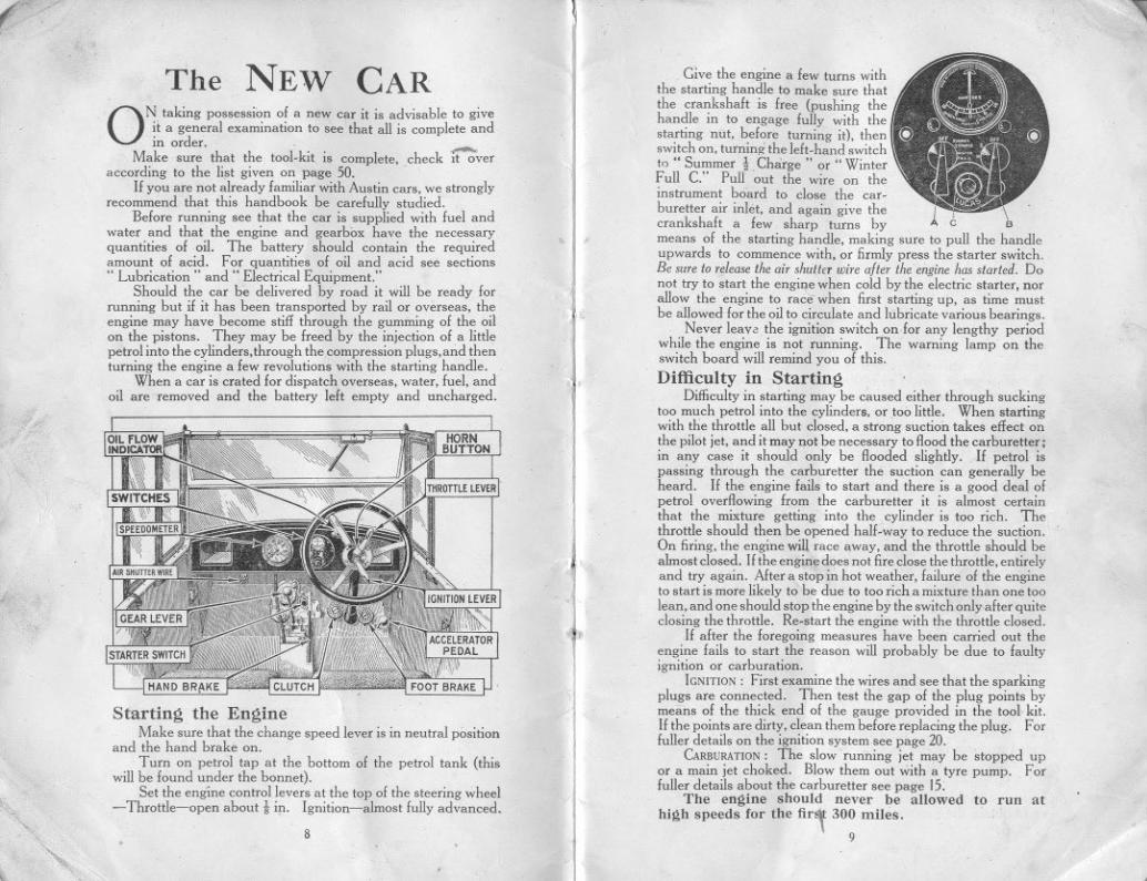
The NEW CAR
ON, taking possession of a new car it is advisable to giveIt a general exammahon to see that all is complete andin order. .
Make sure that the tool-kit is complete, check ~veraccording to the list given on page 50. .
If you are not already familiar with Austin cars, we stronglyrecommend that this handbook be carefully studied.
Before running see that the car is supplied with fuel andwater and that the engine and gearbox have the necessaryquantities of oil. The battery should contain the requiredamount of acid. For quantities of oil and acid see sections" Lubrication" and" Electrical Equipment."
Should the car be delivered by road it will be ready forrunning but if it has been transported by rail or overseas, theengine may have become stiff through the gumming of the oilon the pistons. They may be freed by the injection of a littlepetrol into the cylinders, through the compression plugs, and thenturning the engine a few revolutions with the starting handle.
When a car is crated for dispatch overseas, water, fuel, andoil are removed and the battery lelt empty and nncharged.
Starting the EngineMake sure that the change speed lever is in neutral position
and the hand brake on.Turn on petrol tap at the bottom of the petrol tank (this
will be found under the bonnet).Set the engine control levers at the top of the steering wheel
-Throttle-open about t iJ1. Ignition-almost fully advanced.'" 8
'~
,
u,
Give the engine a few turns withthe starting handle to make sure thatthe crankshaft is free (pushing thehandle in to engage fully with thestarting nut, before turning it), thenswitch on, turning the left-hand switchto "Summer t Charge" or " WinterFull c." Pull out the wire on the ,.instrument board to close the car- I
buretter air inlet, and again give the I, \crankshaft a few sharp turns by A C Bmeans of the starting handle, making sure to pull the handleupwards to commence with, or firmly press the starter switch.Be sureto releasetheair shuttErwire after theenginehasstarted. Donot try to start the engi,\: when cold by the electric starter, norallow the engine to race when first starting up, as time mustbe allowed for the oil to circulate and lubricate various bearings.
Never lean the ignition switch on,for any lengthy periodwhile the engine is not running. The warning lamp on theswitch board will remind you of this.
Dift'iculty in StartingDifficulty in starting may be caused either through sucking
too much petrol into the cylinders, or too little. When startingwith the throttle all but closed, a strong suction takes effect onthe pilot jet, and it may not be necessary to flood the carburetter;in any case it should only be flooded slightly. If petrol ispassing through the carburetter the suction can generally beheard. If the engine fails to start and there is a good deal ofpetrol overflowing from the carburetter it is almost certainthat the mixture getting into the cylinder is too rich. Tbethrottle should then be opened half-way to reduce the suction.On firing, the engine will race away, and the throttle should bealmost closed. If the engine does not fire close the throttle, entirelyand try again. After a stop i;' hot weather, failure of the engineto start is more likely to be due to too rich a mixture than one toolean, and one should stop the engine by the switch only after quiteclosing the throttle. Re-start the engine with the throttle closed.
If after the foregoing measures have been carried out theengine fails to start the reason will probably be due to faultyignition or carburation.
IGNITION: First examine the wires and see that the sparkingplugs are connected. Then test the gap of the plug points bymeans of the thick end of the gauge provided in the tool kit.If the points are dirty, clean them before replacing the plug. Forfuller details on the ignition system see page 20.
CARBURATION:The slow running jet may be stopped upor a main jet choked. Blow them out with a tyre pump. Forfuller details about the carburetter see page IS,
The engine should never be allowed to run at
high speeds for the fir~ 300 milt;s.9
~

(
The NEW CAR
Ot'! taking possessi~n of a new car it is advisable to giveit a general exammatIon to' see that all is complete andin order, '
Make sure that the tool-kit is complete, check it overaccording to the list given on page 50. .
Ifyou are not already familiar with Austin cars, we stronglyrecommend that this handbook be carefully studied,
Before running see that the car is supplied with fuel andwafer and that the engine and gearbox have the necessaryquantities of oil. The battery should contain the requiredamount of acid. For quantities of oil and acid see sections.. Lubrication" and" Electrical Equipment:'
Should the car be delivered by road it will be ready forrunning but if it has been transported by rail or overseas, theengine may have become stiff through the gumming of the oilon the pistons. They may be freed by the injection of a littlepetrol into the cylinders,through the compression plllgs,and thenturning the engine a few revolutions with the starting handle.
When a car is crated for dispatch overseas. water, fuel, andoil are removed and the battery left empty and uncharged.
Starting the EngineMake sure that the change speed lever is in neutral position
and the hand brake on,
Turn on petrol tap at the bottom of the petrol tank (thiswill be found under the bonnet),
Set the engine control levers at the top of the steering wheel-Throttle-open about t iJ1' Ignition-almost fully advanced.
'"8
.'"
\,
,Give the engine a few turns with
the starting handle to make sure thatthe crankshaft is free (pushing thehandle in to engage fully with thestarting nut, before turning it), thenswitch on, turnin" the left-hand switchto .. Summer i Charge" or .. WinterFull C:' Pull 'out the wire on theinstrument board to close the car-
buretter air inlet, and again give the I I \crankshaft a few sharp turns by A C Bmeans of the starting handle, making sure to pull the handleupwards to commence with, or firmly press the starter switch,Be sure to releasethe air shutter wire after the engine has started. Do
not try to start the engi~e when cold by the electric starter, norallow the engine to race when first starting up, as time mustbe allowed for the oil to circulate and lubricate various bearings,
Never leave the ignition switch on for any lengthy periodwhile the engine is not running. The warning lamp on theswitch board will remind you of this.
Difficulty in Starting,Difficulty in starting may be caused either through sucking
too much petrol into the cylinders, or too little. When startingwith the throttle all but closed, a strong suction takes effect onthe pilot jet, and it may not be necessary to flood the carburetter;in any case it should only be flooded slightly. If petrol ispassing through the carburetter the suction can generally beheard. If the engine fails to start and there is a good deal ofpetrol overflowing from the carburetter it is almost certainthat the mixture getting into the cylinder is too rich, Thethrottle should then be opened half-way to reduce the suction.On firing, the engine will race away, and the throttle should bealinost closed. If the engine does not fire close the throttle, entirelyand try again. After a stop i;' hot weather, failure of the engineto start is more likely to be due to too rich a mixture than one toolean, and one should stop the engine by the switch only after quiteclosing the throttle. Re-start the engine with the throttle closed.
If after the foregoing measures have been carried out theengine fails to start the reason will probably be due to faultyignition or carburation.
iGNITION: First examine the wires and see that the sparkingplugs are connected, Then test the gap of the plug points bymeans of the thick end of the gauge provided in the tool kit.If the points are dirty, clean them before replacing the plug. Forfuller details on the ignition system see page 20,
CARBURATION:The slow running jet may be stopped upor a main jet choked. Blow them out with a tyre pump: Forfuller details about the carburetter see page 15.
The engine should never be allowed to run athigh speeds for the first 300 miles.
9
,
.'
'\
t"
CONTROL OF THE CARSetting of Control Levers
j\FTER having started the engine, keep the ig
,
nition lever inthe advanced pos[tion; should the engine commence to
, " rumble" or run roughly, retard the lever, but advance Iit ,again as soon as the load on the engine is lessened. The" gas" lever should be set generally for slow running and thespeed of the car controlled by the accelerator pedal.
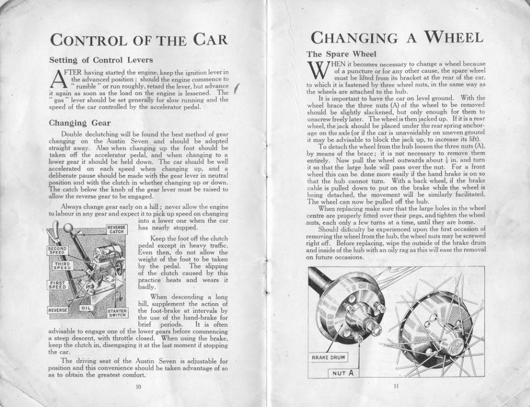
Changing GearDouble declutching will be found the best method of gear
changing on the Austin Seven,,- and should be adoptedstraight away. Also when changing up the foot should' betaken off the accelerator pedal, and when changing to alower gear it should be held down. The car shOllld be wellaccelerated on each speed when changing up, and adeliberate pause should be made with the gear lever in neutralposition and with the clutch in whether changing up or down.The catch below the knob of the gear lever must be raised toallow the reverse gear to be engaged.
Always change gear early on a hill; never allow the engineto labour in any gear and expect it to pick up speed on changing
into a lower one when the carhas nearly stopped.
Keep the foot off the clutchpedal except in heavy traffic.Even then, do not allow theweight of the foot to be takenby the pedal. The slippingof the clutch caused by thispractice heats and wears itbadly.
When descending a longhill, supplement the action ofthe foot-brake at intervals bythe use of the hand-brake forbrief periods. It is often
advisable to engage one of the lower gears before commencinga steep descent, with throttle closed. When using the brake,keep the clutch in, disengaging it at the last moment if stoppingthe car.
The driving seat of the Austin Seven is adjustable forposition and this convenience should be taken advantage of soas to obtain the greatest comfort, '
'" 10
."
"""
,I
~
CHANGING A WHEELThe Spare Wheel
WHEN it becomes necessary to change a wheel because. of a puncture or for any other cause, the spare wheel
must be lifted from its bracket at the rear of the car,to which it is fastened by three wheel nuts, in the same way asthe wheels are attached to the hub.
It is important to have the car on level ground. With thewheel brace the three nuts (A) of the wheel to be removedshould be slightly slackened, but only enough for them tounscrew freely later. The wheel is then jacked up. If it is a rearwheel, the jack should be placed under the rear spring anchor-age on the axle (or if the car is unavoidably on uneven groundit may be advisable to block the jack up, to increase its lift).
To detach the wheel from the hub loosen the three nuts (A),by means of the brace; it is not necessary to remove thementirely. Now pull the wheel outwards about! in. and turnit so that the large hole will pass over the nut. For a frontwheel this can be done more easily if the hand brake is on sothat the hub cannot turn. With a back wheel, if the brakecable is pulled down to put on the brake while the wheel isbeing detached, the movement will be similarly facilitated.The wheel can now be pulled off the hub.
When replacing make sure that the large holes in the wheelcentre are properly fitted over their pegs, and tighten the wheelnuts, each only a few turns at a time, until they are home.
Should diiticulty be experienced upon the first occasion ofremoving the wheel from the hub, the wheel nuts may be screwedright off. Before replacing, wipe the outside of the brake drumand inside of the hub with an oily rag as this will ease the removalon future occasions.
NUT A
11
.(

(".
PERIODICALATTENTIONS
ON this and the opposiie page is a handy. . summary 01 all the attentions described in
this handbook. The attentions under thedaily. weekly. and monthly headings are based onthe assumption that the maximum mileage perweek does not exceed 300.
The occasional attentions should not be neglectedil the car is to continue to run efficiently. Whenrelerring to the attentions below. see the lubrica-tion chart on page 14.
"Daily Attentions
1. Examine water level in radiator' andfill up to within 2 in. of the top. Alwaysuse'" the strainer when re-filling asdirty water will cause the radiatorfilm to become choked.
2. Examine oil 'level in the crankcaseand add more oil if necessary. Thetell-tale dipper rod indicates the levelof the oil (see illustration, page 27).
3. Fill up the petrol tank if necessary.Care should be exercised not to overfillthe tank and spill the petrol overthe engine.
Weekly Attentions ..
1. With the grease gun charge-Front spring shackle pins (4).Rear spring pins (2).Front wheel swivel pins (2).Steering cross tube (2).
2. Oil the following-Handbrake gear.Pedal gear and joints.Engine control joints.Clutch release ring.Rear brake cam spindles (2).Steering side tube joints (2).
3. Examine both sets of brakes, and adjustif necessary.
r-" 12
'- "
,
(
4. Inject high speed grease (such asMessrs. Stern's" Diamol") into theuniversal joint at the rear end of thepropeller shaft and yellow grease intothe front eud of the torque tube.
5. Test the tyres for correct pressure andexamine them for cuts (see page 49).
6. Give one turn to the cap of the lubricatorfor the main distributor bearing, page 21.
Monthly Attentions
1. Examine the oil level in the gearboxwhich should contain two-thirds ofa pint, or measure 2-21 iu. deep.
2. Charge the back axle case with a gunfulof grease and oil mixed half and half,using the special adapter on the grease gun.
3. Fill all the hubs with grease, asdescribed on pages 30 and 31.
4. Charge with grease the steering wormcase through the nipple.
5. Examine the battery and see that theconnections are tight. For details seepage 34.
6. Give a charge of grease to the nippleon the fan spindle.
Occasional Attentions
" ,
Examine all bolts and nuts. such as road spring clips,cylinder head nuts. wheel nuts (these three especially when thecar is new). examine other parts such as steering connections.the radius rod anchorage below the gearbox. and the torquetube socket. neglect 01 which points might be lollowed by anexpensive repair. and the inability to use the car lor a lengthyperiod.
Occasionally clean the petrol filler and float chamberstrainers. the radiator filler strainer. the oil filler strainer. and theoil reservoir gauze (when the engine oil can be changed); alsoensure that the oil jets. .under the plugs on the crankcase. areclean. Drain the gearbox and refill with fresh oil (i pint).
Flush the radiator through. Clean the ignition dis-tributor, and the contact breaker points (adjust the latter),the dynamo and starter commutators. Clean and lubricatethe shock absorbers. adjust the tappets. and the fan belt,decarbonize the engine and grind-in the valves. Check thealignment of the front wheels. For details of these attentionsreler to the pages that follow. IT
1
13
c

rI- ,
I,
Il
t'", '"" ,
,LUBRICATION CHART
TheCARBURETTER
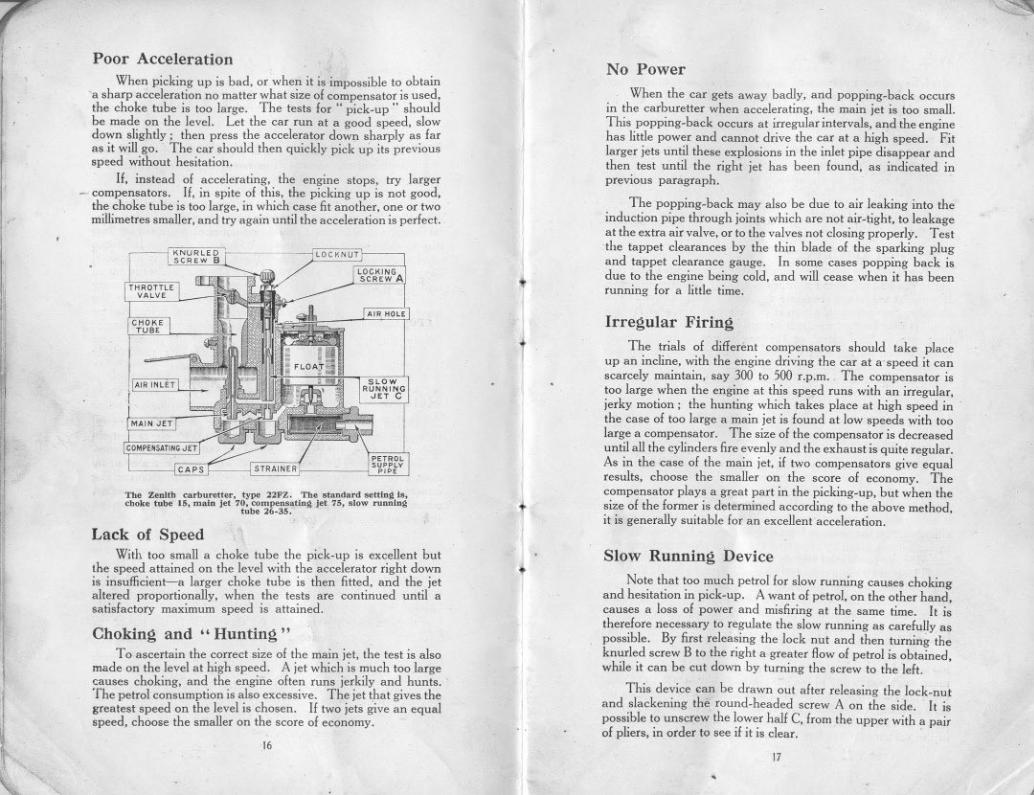
THE following notes have reference to the Zenithcarhuretter, which is adjusted by determining thecorrect sizes of the choke tube, main jet and compensator,
The purpose of the choke tube is to obtain the correct velocityof air around the jet in order to get the best mixture at all speeds.The main jet has most influence at high speeds, The com-pensator, which corrects the irregularities of the main jet flowdue to differences in engine speed, has the greatest influenceat slow speeds. Besides these three parts there is a specialdevice to provide for slow running. The carburetter is tunedand set at the works to give the best results under ordinaryconditions; should the car be taken to districts where theatmospheric conditions vary considerably, or a different fuel beused, it may be advisable to adjust the carburetter accordingly.Before making alterations to the carburetter make quitesure that the engine is in good running order particularlythe ignition.
~ ~:J~ ...1:III Z1II~01-~~::EZ
III 0IIIIIIIII~111>111'"«:>«111 111""0:-0:-0000
eO8C
Method of AdjustmentBefore altering the carburetter setting, turn off the petrol
by means of the tap underneath the tank. A jet key is sent outwith each car for the purpose of taking out the main and com-pensating jets. The caps below the jets .must be removed bymeans of the adjustable spanner, when the jets can beunscrewed with the special key. When replacing either,make sure that they have washers on them, well down onthe shoulder.
1
I
I
To remove the choke tube it is necessary to separate thecarburetter from the induction manifold flange, first havingdisconnected the throttle and air strangler controls and thepetrol pipe at its union on the float chamber, The throttle fixingscrew should then be removed, allowing the throttle spindleto be withdrawn and the throttle to be lifted from the carburetterbore. On unscrewing the choke tube locking screw, the choketube will usually fall clear if the carburetter is turned upsidedown; in any event a slight tap will usually loosen it. Whenrefitting a choke tube make sure that its narrowest internaldiameter is downwards, and that it beds down on the ledge.round the bottom of the carburetter bore; then the lockingscrew can be tightened. When refitting the carburetter to theinduction manifold, ensure that there is a good joint betweenthe flanges.
14
.~ /
15 --
7 ~
Poor Acceleration
When picking up is bad, or when it is impossible to obtain"a sharp acceleration no matter what size of compensator is used,the choke tube is too large. The tests for" pick-up" shouldbe made on the level. Let the car run at a good speed, slowdown slightly; then press the accelerator down sharply as faras it will go. . The car should then quickly pick up its previousspeed without hesitation.
If, instead of accelerating, the engine stops, try larger- compensators.If, in spite of this, the picking up is not good,
the choke tube is too large, in which case fit another, one or twomillimetres smaller, and try again until the acceleration is perfect.
No Power
CHOKETUBE
LOCKNUT !
When the car gets away badly, and popping-back occursin the carburetter when accelerating, the main jet is too small.This popping-back occurs at irregular intervals, and the enginehas little power and cannot drive the car at a high speed. Fitlarger jets until these explosions in the inlet pipe disappear andthen test until the right jet has been found, as indicated inprevious paragraph.
The popping-back may also be due to air leaking into theinduction pipe through joints which are not air-tight, to leakageat the extra air valve, or to the valves not closing properly. Testthe tappet clearances by the thin blade of the sparking plugand tappet clearance gauge. In some cases popping back isdue to the engine being cold, and will cease when it has beenrunning for a little time.
:j
I
j
~
~I
THROTTLEVALV'
AIR HOLE
Irregular Firing
The trials of different compensators should take placeup an incline, with the engine driving the car at a'speed it canscarcely maintain, say 300 to 500 r.p.m. The compensator istoo large when the engine at this speed runs with an irregular,jerky motion; the hunting which takes place at high speed inthe case of too large a main jet is found at Iow speeds with toolarge a compensator. The size of the compensator is decreaseduntil all the cylinders fire evenly and the exhaust is quite regular.As in the case of the main jet, if two compensators give equalresults, choose the smaller on the score of economy. Thecompensator plays a great part in the picking-up, but when thesize of the former is determined according to the above method,it is generally suitable for an excellentacceleration.
[A" iNLET 1
MAINJET
COMPENSATING JET
CAPS
Tb. Z..tth ,arhn""", typ' 22FZ. Th. ,tandard s."'ng Is,,hnk. tuh. 15, main j.t 70, oomp ting j.t 75, ,lnw ~nnlng
tnb. 26.35.
Lack of SpeedWith too small a choke tube the pick-up is excellent but
the speed attained on the level with the accelerator right downis insutlicient-a larger choke tube is then fitted, and the jetaltered proportionally, when the tests are continued until asatisfactory maximum speed is attained.
Choking and" Hunting"To ascertain the correct size of the main jet, the test is also
made on the level at high speed. A jet which is much too largecauses choking, and the engine often runs jerkily and hunts. .
The petrol consumption is also excessive. The jet that gives thegreatest speed on the level is chosen. If two jets give an equalspeed, choose the smaller on the score of economy.
Slow Running Device
Note that too much petrol for slow running causes chokingand hesitation in pick-up. A want of petrol, on the other hand,causes a loss of power and misfiring at the same time. It istherefore necessary to regulate the slow running as carefully aspossible. By first releasing the lock nut and then turning theknurled screw B to the right a greater flow of petrol is obtained,while it can be cut down by turning the screw to the left.
This device <an be drawn out after releasing the lock-nutand slackening the round-headed screw A on the side. It ispossible to unscrew the lower hall C. from the upper with a pairof pliers, in order to see if it is clear. .
t6
[
"
17.
,

r~
)
I
II
~I
III
"
li,.,[
,."
I
111
I
ili
~I
1
:1.
d,
There are other factors quite apart from the carburetterwhich have great influence on slow running (slow running when
-the engine is out of gear and the car is stationary),These factors are:-
Joints .not air-tight. Valve guides worn. Valves notseating. Ignition too much advanced.
Engine Misfires and StopsIn tests made as in the last instance. the engine misses fire
now and again, the transmission receives jerks, and the enginefinally stops. In this case fit a larger compensator until theengine runs regularly.
The Float Chamber,Petrol leakage from the float chamber may be due to the caps
under the jets not being tight, or a leaking petrol pipe union.If no leakage seems possible at these points, suspect floatchamber derangement, which is causing petrol to overflow thejets. It may be that the float control is out of adjustment, thefloat may be perforated, or the needle not seating properlyowing to dirt on the needle seating. The remedy for the lastmentioned defect is obvious; the first two defects should beleft to an expert to remedy. When replacing the float chambercover, ensure that the needle ha~ entered its seating, and is freeto be moved by the float: also that the cover beds downproperly, then secure it with the clip;
Petrol FlowIf the petrol supply from the tank is unrestricted yet
difficult starting points to insufficient petrol, there is a restrictionsomewhere in the carburetter. First, see that the air vent in thefloat chamber cover, under the retaining clip, is clear. Shouldit be so, the next point to examine is the filter below the floatchamber, and the passage from it to the needle seating. Accessto this filter is given by removing the petrol pipe union and un-screwing the petrol inlet nut, on the bottom of the float chamber.
The slow running tube and jet may be stopped up. Removethe slow running tube bodily, having loosened its locking screw.In the bottom of the tube is a small filter which can be prised outand cleaned. The bottom portion of the tube, comprising thejet, may be then unscrewed from the top portion, and the jetcleaned if stopped up; two flats on the jet allow a small spannerto be used to unscrew it. Lastly the compensating or mainjets may be choked. Remove them and clear them. Neverinsert anything in any of the jets; always blow through to clearthem; a tyre pump can be used if desired. When refitting theslow running tube ensure that it beds down to its collar at thetop, with the small projection under the collar fitting the groove
. in the carburetter casting; then tighten the locking screw,
16
\
t.
1
.1
f..
I
III
"""IIi
Difficulty in StartingThis may be due to several causes-
Float chamber air vent stopped up (see previous page).Slow running tube stopped up (see previous page),Plug points too far apart, See" Ignition System,"Ignition lever badly placed. See next paragraph.Jets choked up (see previous page).
With variable ignition there is generally a particularlyfavourable setting for easy starting. One who is continuallyusing a car soon recognises this position.
STANDARD REPAIRCHARGES ~
THE following adjustments and repairs described in thishandbook are included in the Austin Seven Scheduleof Charges for Repairs, which quotes over ninety prices
for repairs to the Austin Seven, Owners will find it to theiradvantage to have their car adjustments and repairs effectedby Austin agents at these standard prices,
Greasing spring shackles, steering and brake, and othersmall connections,
Ditto, but including rear axle, universal joint, steering boxand front hubs.
Taking down, cleaning and greasing all road springs,reassembling with new bolts and bushes where required.Dismantling shock absorbers, then cleaning and adjustingand refixing,Adjusting and compensating brakes.Relining brakes, front or rear.Removing cylinder head; decarbonising and grinding invalves: adjusting tappets and tuning-up engine on theroad.Fitting new cylinder head and/or gasket.Adjusting valve tappets, cleaning and adjusting contactbreaker, distributor and sparking plugs; cleaning outcarburetter jets,Fitting new valves,Removing base chamber, cleaning oil filter, examininginterior of engine, and refilling with new oil.Removing dynamo from car; cleaning and adjusting,examining battery and connections, and refilling batterywith acid as required.Tracking up front wheels by adjusting length of crosssteering tube,Adjusting mesh of steering worm and wheel.
19
J
I
IT
!/
~j
ill!!lill
I!ii
I1]1
l:1
\, """
The IGNITION SYSTEM
THE recommendations that follow apply to the C.A.V.-Lucas ignition equipment.The set should be examined occasionally and the
following attentions given. only if they seem necessary.
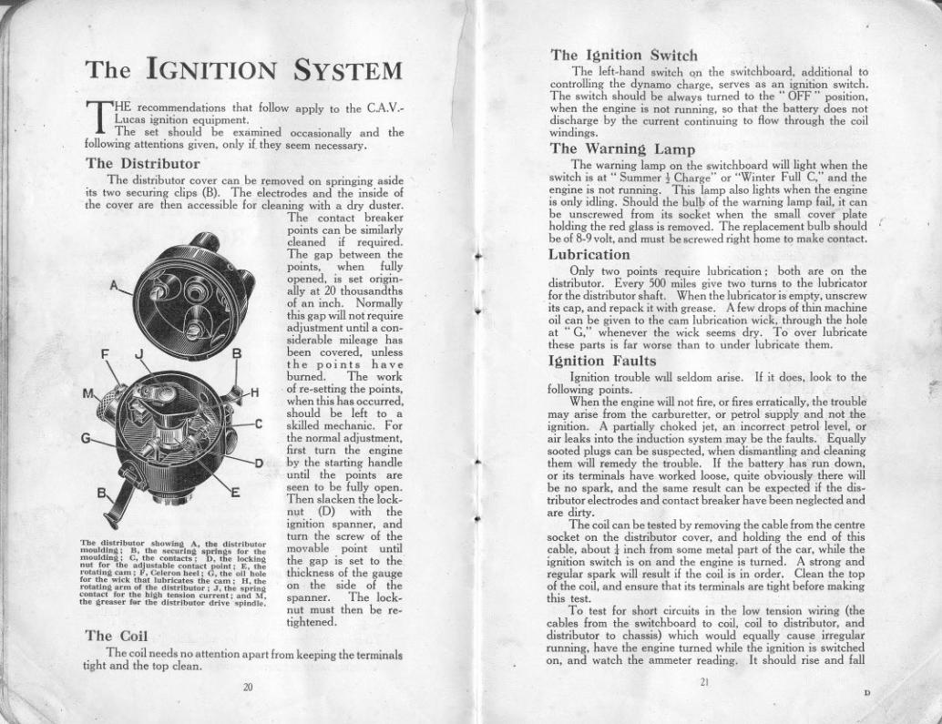
The DistributorThe distributor cover can be r~moved on springing aside'
its two securing clips (B). The electrodes and the inside ofthe cover are then accessible for cleaning with a dry duster.
The contact breakerpoints can be similarlycleaned if required.The gap between thepoints, when fullyopened, is set origin-ally at 20 thousandthsof an inch. Normallythis gap will not requireadjustment until a con-siderable mileage hasbeen covered, unlessthe points haveburned. The work
. of re-setting the points,when this has occurred.should be left to askilled mechanic. Forthe normal adjustment,first turn the engineby the starting handleuntil the points areseen to be fully open.Then slacken the lock-nt,lt (D) with theignition spanner, andturn the screw of themovable point untilthe gap is set to thethickness of the gaugeon the side of thespanner. The lock-nut must then be re-tightened.
A
F
G
The dl"ributor 'bowiug A, the di"ributormoulding; B, the ,&uring ..ring, for themoulding; C, the contac"; D, tbe [ockingnnt for tbe adjn"abl. contact point; E. therotating cam; F, Celeron beel; G, the 011 bolefor the wick tbat lubricat.. the cam; H, therotating arm of the dl"rlbutor; J, the ,pringconta" for tbe blgh ten,ion current; and M,the gream fnr tb. dl'tributor drive ,pindle.
The CoilThe coil needs no attention apart from keeping the terminal.
tight and the top clean.
20
III\
.~
."
I!I..
t
""Ill
The Ignition Switch .
The left-hand switch on the switchboard, additional tocontrolling the dynamo cha'rge, serves as an ignition switch.The switch should be always turned to the" OFF" position,when the engine is not running, so that the battery does notdischarge by the current continuing to /low through the coilwindings.
The Warning LampThe warning lamp on the switchboard will light when the
switch is at " Summer:\- Charge" or "Winter Full C," and theengine is not running. This lamp also lights when the engineis only idling. Should the bulb of the warning lamp fail, it canbe unscrewed from its socket when the small cover plateholding the red glass is removed. The replacement bulb shouldbe of 8-9 volt, and must be screwed right home to make contact.Lubrication
Only two points require lubfication; both are on thedistributor. Every 500 miles give two turns to the lubricatorfor the distributor shaft. When the lubricator is empty, unscrew
. its cap. and repack it with grease. A few drops of thin machineoil can be given to the cam lubrication wick, through the holeat "C," whenever the wick seems dry. To over lubricatethese parts is far worse than to under lubricate them.
Ignition FaultsIgnition trouble will seldom arise. If it does, look to the
following points.When the engine will not fire, or fires erratically, the trouble
may arise from the carburetter. or petrol supply and.nottheignition. A partially choked jet, an incorrect petrol level, orair leaks into the induction system may be the faults. Equallysooted plugs can be suspected, when dismantling and cleaningthem will romedy the trouble. If the battery has run down,or its terminals have worked loose, quite obviously there willbe no spark, and the same result can be expected if the dis-tributor electrodes and contact breaker have been neglected andare dirty. .
The coil can be tested by removing the cable from the centresocket on the distributor cover, and holcling the end of thiscable, about! inch from some metal part of the car, while theignition switch is on and the engine is turned. A strong andregular spark will result if the coil is in order. Clean the topof the coil, and ensure that its terminals are tight before makingthis test.
To test for short circuits in the Iow tension wiring (thecables from the switchboard to coil, coil to distributor, anddistributor to cbassis) which would equally cause irregularrunning, have the engine turned while the ignition is switchedon, and watch the ammeter reading. It should rise and fall
:
"":;".
21D
,
!
!llrij
If'
!,
I":<1
~t.~\,
as the contact hreaker points close and open. This test willalso indicate if the contact hreaker is functioning correctly. Ifthe contacts remain open, or do notfully close, the reading willnot fluctuate.
)f the high tension cahles from the distributor to the plugs,are not pushed home into their sockets in the distributor, mis-firing will similarly occur. Or, if the rubber insulation on thesecables show signs of perishing and cracking, there may beleakage of the current, giving rise to the same symptoms. Re-newing the cables is then the remedy.
If after verifying these points, the trouble remains undis-covered, the equipment should be examined and tested by thenearest service depot of the makers.
When Leaving the CarWhen the -car has to be parked or left in the street for any
period, the distributor cover can be lifted, and the rotatingdistributor arm removed from its mounting above the cam;it just pulls off without turning. The car is then secure againstany attempts at theft, and the distributor arm can be carriedin the pocket until the car is to be used. again. When refittil)git, note that the projection up inside its moulding, fits the slotcut in the top of the spindle on which it mounts, so that it islocated for correct timing.
~
II
'f
,TIMING IGNITION ,THE
In timing the ignition (which is only necessary if the dis-tributor, with or without the dynamo, has been removed fromthe car) the first operation is to rem6ve all the sparking plugs,except the front-No. I-and turn the crankshaft by the startinghandle until compression is felt. This means that'No. I cylinderwill be the next one to fire. ,
'.;..0
Flywheel Timing MarksThen remove the starter motor with its casing (inside the
car) by unscrewing the securing studs, one on each side of thecasing, and lifting the assembly clear vertically off the locatingdowel on the crankcase. A line will be seen on the back of theflywheel. marked 1 and 4 (see illustration on page 28). Thisline is parallel to the throws of the crankshaft, and when thisline is vertical it naturally follows that Nos. I and 4 pistons areat the top of their stroke. In this case, howe.;er,..weare onlydealing with No. I. Now turn the flywheel uniiL,this line is1t in. to 2 in. before the top centre. (We cannot quote adefinite figure as this depends on the characteristics of theparticular engine). This is the position at which the sparkshould take place at the sparking plug, when the ignition
I'~
.'
.1
" 22
~I
'L,I" ,i!i;!;r,y&
"
is fully advanced, and the ignition lever on the steeringwheel is set at the full advanced position.
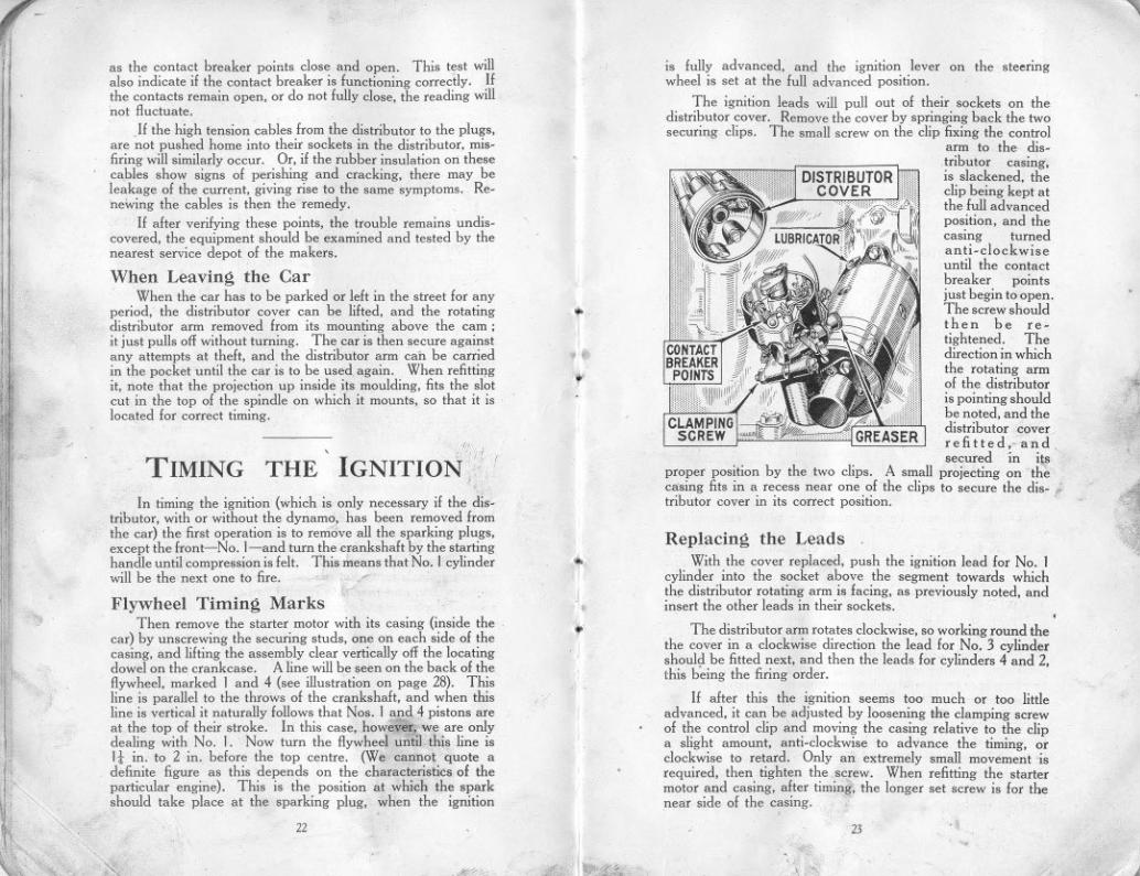
The ignition leads will pull out of their sockets on thedistributor cover. Remove the cover by springing back the twosecuring clips. The small screw on the clip fixing the control
arm to the dis-,tributor casing,is slackened, theclip being kept atthe full advancedposition, and thecasing turnedanti-clockwiseuntil the contactbreaker pointsjust begin to open.The screw shouldthen be re-tightened. Thedirection in whichthe rotating armof the distributoris pointing shouldbe noted, and thedistributor coverrefitted,.. and,
secured in iI!"proper position by the two clips. A small projecting on thecasing fits in a recess near one of the clips to secure the disc ;'tributor cover in its correct position.
?+~.
~1iiI
Replacing the LeadsWith the cover replaced, push the ignition lead for No. 1
cylinder into the socket above the segment towards whichthe distributor rotating arm is facing, as previously noted, andinsert the other leads in their sockets.
The distributor arm rotates clockwise, so working round thethe cover in a clockwise direction the lead for No. 3 cylindershoul,! be fitted next, and then the leads for cylinders 4 and 2,this being the firing order.
If after this the ignition seems too much or too littleadvanced, it can be adjusted by loosening the clamping screwof the control clip and moving the casing relative to the clipa slight amount, anti-clockwise to advance the timing, orclockwise to retard. Only an extremely small movement 'isrequired, then tighten the .screw. When refitting the startermotor and casing, after timing, the longer set screw is for thenear side of the casing.. ,
23
.~."",~..~~
"
"
"'Ill
TheCOOLING SYSTEM
The entire circulating system should be tboroughly flushedout occasionally. To do this open the drain tap at the bottom,place a hose in the filler, and run fresh water through.
Trouble arising from a damaged radiator generallynecessitates its dismantling and despatch to a repair depot.
THE cooling of the e.
ngine is maintained by a capaciousradiator which should be filled, with rain water, if
. available, up to within 2 in. of the top of the filler. Thecapacity of the radiator, pipes and cylinder jackets is9-10 pints.
How To USE THEGREASE GUN
'ill
ill,
..1
'.iili
1Ii
l./
.'..':,"~I~::1
In Cold WeatherCare should be taken to see that the water is drained off
completely, f~r, in case of freezing, it will do harm by lodging insmall spaces and fracture of the cylinder block may result, InGreat Britain, the climate does not very often call for the coolingsystem to be drained, but it is well to err on the right side andtake. due precaution against damage if frost be threatened,
Glycerine mixed with the water will reduce its freezing pointby several degrees, If added it should be in the proportion of15% to 20%, In cold weather use the Austin radiator muff.
To prevent the gradual formation of deposits in the coolingsystem, with consequent impeding of the circulation, the use ofhard water should be avoided. Rain-water, syphoned from thetop of the barrel where it is clean, should be used, or, failingthat, water that has been boiled.
1'¥
Screw the handle right out. Unscrew the extension pieceby the knurled nut at the base of the barrel and fill the barrelwith grease; then replace. Give the handle one completeturn: this fills the telescopic extension piece at the end of thegun which will project. Now place the end of the gun on thenipple attached to that part of the car which it is desired togrease, and push. The extension piece closes and dischargesthe grease into the nipple.
Give the handle another turn and the gun is once morechargee.!. Continue until the barrel is empty and then refill.
For the back axle a special adapter is used on the gun inplace of the standard telescopic end. This adapter screwsihto the axle, in place of the plug. When replacing the plug,do not omit its washer. It is important not to let dirt get intothe adapter which; when not in use, is screwed on to theside of the gun.
,
'
f',
I;:.,"
Causes of OverheatingOverheating may be attributed to one or more of thefollowing:Slack fan belt. The belt can be tightened by turning thefan spindle in its bracket after loosening the clamping-nut.Excessive carbon deposit in cylinders. See" RunningAdjustments."
. Running with ignition too far retarded.Using oil of poor quality, or lack of oil in the reservoir.See" Engine Lubrication." .
Partial choking of the oil jets. See" Engine Lubrication."Improper carburetter adjustment, giving 'a mixture too richor too weak. See" The Carburetter."
Failure of water to circulate, because of choked radiatortubes, water level below the tops of the radiator tubes, or lossof water through leakage from connections.
Overcooling is almost as bad as overheating. If the enginetends to be too cool, use a radiator muff, or possibly, in winter,the fan belt can be removed without the engine running too hot.
DON'T!'"
~!1
Don't, pleasedon't-Don't leave the car in gear with the handbrake off.Don't make a fast run. with the radiator muff down.Don't fill the radiator with cold water whe'; the engine is hot.Don't try to turn the engine without first pushing the starting-. handle in to engage fully with the starting nut.
Don't be ,cruel to the starter if the engine will not fire.Don't touch th" reverse catch when changing gear.Don't put an excessive quantity of lubricant in the gear box.Don't pour oil into the engine with the strainer removed.Don't forget the ignition switch when starting up.Don't leave the ignition switched on when the engine is
not running. .
Don't coast with the engine running and the clutch held out.Don't run the engine in a closed garage. (The exhaust gases
are highly toxic and a very small amount in a restrictedatmosphere will produce grave, if not fatal, results.)
25
.,,..
24".""
~

'<
l'
"
LUBRICA TION
Choi~e of Lubricants
FOR the engine or gear box use one of the following oils:-Stern's" Sternol W.W." Heavy; "Mobiloil BB."; Price's"Motorine C:'; Speedwell" Sans Egal Zero "; "Triple
Shell" ; "Speedolene B. Heavy"; Texaco "Heavy";Filtrate" Extra Heavy"; "Royal Snowdrift 3 "; Wakefield's"Castrol XL"; Duckham's" Adcol N P 3-4"; and" Veedol" Heavy No. 4.
Use ordinary" engine" oil in a small can, and ordinaryyellow grease for greasing.
Both these lubricants can be obtained from any garage orrepair shop.
Use Stern's" Diamol" or Price's High Melting PointGrease {or the rear universal joint of the drive shaft.
The EngineFor the engine, where the recommended oils are not
obtainable, oil of approximately the same constituents andviscosity should be used. If the oil is too thick it willtend to clog and carbonise, and if too thin it might lead to "
scoring of the pistons and bearings. Assurance that oil iscontinuously circulating is given to the driver by means ofthe tell.tale button on the instrument board, which protrudeswhen the oil is circulating.
It is essential that all receptacles for oil be kept perfectlyclean. Dirty oilleads to unduewear of allbearings,or might even clogup the oilingsystem and prevent
it ,,:orking, thuscausmg an engmeseizure and muchtrouble and ex.pense. The oilfiller strainer (A)is detachable forcleaning, After thefirst 500.800 milesrunning, drain theoriginal oil from
j,
I,IUti
,:
1i
\~"'j
11:
1
1
"
"
',
H"","il'
P.
II~
I1
iJI,,:"
IH'IIt,.1
"
,
'
,
~"
'
,
,i
I
I'III
I"I'
'Ii,"11""\:
~
"
'I
~ \
I
f
',.f,
",
I!
J26
ItI
.,
PUMP
the reservoir by'removing the plug in the bottom, while theengine is hot, Drain the reservoir completely, Never pouroil into the engine except through the strainer. "
After the first re.filling it is advisable to change the oil in theengine entirely after every I,200 to I ,500 miles running or sooner.
Every 2,400-3,000 rlliles remove the oil reservoir. The"gauze oil tray will then be accessible for removal. Carefullyclean the gauze and remove all dirt from inside the reservoirand replace them. Carefully remake the joint with the packingwasher, covering both sides of it with grease. When tighteningup the nuts holding the oil reservoir to the crankcase, do notpull up one nut tight, but tighten each nut equally, a little ata time, See that the drainplug is screwed up tight, then fill thecrankcase with oil to the maximum level as shown on thedipper rod, B. About half a gallon will be enough to fill.
Always inspect the level of the oil and add, enough to fill,to the correct level before starting on a long journey.
The oil level should not be allowed to go below! inch onthe bottom of the dipper rod, It is advisable to wipe the dipperrod before taking the reading of the level, and the readingshould only be taken when the engine is not running and thecar is on the level ground.
The main bearings of the engine are of the roller type, and'the oily vapour in the crankcase is quite sufficient to lubricatethese. ..
Tte pistons are also lubricated by the oily vapour.Lubrication of the big.ends is effected by catching oil from
the pump.fed jets m pockets on the crankshaft webs.
21
.....
-- -It is advisable to make sure these jets are always clear and
to do so the plugs over the jets (see illustration) should beoccasionally removed and a piece of stiff wire, not above 1Ir in.diameter, inserted through the jets. This prevents foreignmatter accumulating in the jets and choking them.
11
,
'~,
11
Gea\box . .A suitable oil for the gearbox is the same as that used in
the engine; but if for any reason another brand of oil is usedit should be of about the same consistency and no thicker.otherwise it will not reach all the bearings. The depth of theoil should never be less than I in. or more than 2! in. It can bemeasured by the engine clipper rod inserted through the fillerplug hole, but not while the engine is running. Themaximum quantity is approximately i pint. The correct oillevel should be maintained; excess of oil will leak from the'bearings and seriously affect the clutch. causing' it to slip;on the other hand there must be sufficient oil to prevent wear.
The gearbox should be drained entirely afte; the first500-800miles. and then after every 4.000or 5.000miles, whenany grit. etc.. which may have collected willdrain away through'the plug hole ,~in the sump. FLYWHEEL
The gearbox ~drain plug Iflllholds the clutchpit drainholecoverinpositionand this shouldbe replacedwhen the drainplug is refitted.
ClutchThe clutch
surfaces being of a fabric material must be kept free from oiland grease, or the clutch will fail to grip. It is necessary tolubricate the operating ring at point A. as shown on the sketch,once a week with oil.
{I
t
.1
I
I
JSteering Gear
To obtain easy steering it is important to give it regularattention as regards lubrication. The grease gun nipple is onthe top of the worm cas.e,and if a charge is given once a monthit is sufficient to lubricate the bearings of the worm and wormwheel and also lubricate the worm itself. However, if too muchgrease is injected at this point, it will get up the columnand exude round the steering wheel. The bearing at the
.,
~28
.
top of the column. just under the steering wheel can be given alittle oil from the oil-can. The steering connections on the siderod are best lubricated by means of an oil-can which ejects theoil undei pressure. into the sockets, and the nipples at the endof the cross rod should be given a charge of grease once a week.
Rear AxleFor the fear axle, attention every 1.200to 1.500miles should
be sufficient. A mixture of yellow grease and engine oil ofequal parts should be used. It is injected into the axle. usingthe special adapter on the grease gun barrel (in place of thetelescopic end) which screws into the centre casing of the axlewhen the small plug has been removed with a -firin.box spanner.The gun handle is screwed down to inject the grease. Whenreplacing the plug see that the washer is not omitted. Do notinject too much grease at anyone time as the felt rings will failto hold this grease in the axle case. and it will then leak throughon to the brakes and prevent them from being effective.
Rear Universal JointFor the rear univ~r5aLjoint a good quality" high speed ..
grease should be used. This is of a dark brown colour. andwill remain in the joint longer than the ordinary yellow grease.
The rear universal joint being of metal should be one ofthe points to have stricf weekly attention. The car ismoved until the plug in the universal joint is facing upwards(if it i. not already so) and the grease is injected by means ofthe grease gun using the special screw-in adaptor. Access isgained by moving aside a small cover in the floor of thebody. This same cover gives access to the nipple on the endof the torque tube which should receive ordinary yellowgrease every week. .
Brake GearOn each of the rear brakes there is a lubricator for oiling
the cam spindle bearing. These and all other joints, etc.,should be oiled once a week.
The front brake cam spindle is lubricated from the swivelpin as shown at B,. in the illustration overleaf.
, Front AxleThe swivelpins are lubricated with the grease gun and
should receiveattention once a week.
Radius Rod AnchorageOil should be applied occasionally to the cups and ball
flange. forming the radius rod anchorage on the front crossmember. just below the rear of the gearbox.
29
~

--!
'Ii.I'.
~1111
i~,
Ill'".1
~
It is advisable to make sure these jets are always clear andto do so the plugs over the jets (see illustration) should beoccasionally removed and a piece of stiff wire, not above ~ in.diameter, inserted through the jets. This prevents foreignmatter accumulating in the jets and choking them.
I'
I'i,I"
Gearbox'A;;;;:itable oil for the g~arbox is the same as'that used in
the engine; but if for any reason another brand of oil is usedit should be of about the same consistency and no thicker,otherwise it will not reach all the bearings. The depth of theoil should never be less than I in. or more than 2! in. It can bemeasured by the engine clipper rod inserted through the fillerplug hole, but not while the engine is running. Themaximum quantity is approximately i pint. The correct oillevel should be maintained; excess of oil will leak from the'bearings and seriously affect the clutch, causing' it to slip;on the other hand there must be sufficient oil. to prevent wear.
The g~arbox should be drained entirely after the fir~t500-800miles, and. then after every 4,000 or 5,000 miles, whenany grit, etc.. which may have collected will drain away through'
the plug hole 's,.in the sump. FLYWHEEL
The gearbox 'Ill "'-'\idrain plug If/IIholds the clutchpit drainholecoverin positionand this shouldbe replacedwhen the drainplug is refitted.
ClutchThe clutch
surfaces being of a fabric material must be kept free from oiland grease, or the clutch will fail to grip. It is necessary tolubricate the operating ring at point A, as shown on the sketch,once a week with oil.
"(
..
.t
,k
«
t
Steering GearTo obtain easy steering it is important to give it regular
attention as regards lubrication. The grease gun nipple is onthe top of the worm case, and if a charge is given once a monthit is sufficient to lubricate the bearings o(the worm and wormwheel and also lubricate the worm itself. However, if too muchgrease is injected at this point, it will get up the columnand exude round the steering wheel. The bearing at the
.,
I'
28
~top of the column, just under the steering wheel can be given alittle oil from the oil-can. The steering connections on the siderod are best lubricated by means of an oil-can which ejects theoil under pressure, into the sockets, and the nipples at the endof the cross rod should be given a charge of grease once a week.
Rear AxleForthe lear axle, attention every 1,200to 1.500miles should
be sufficient. A mixture of yellow grease and engine oil ofequal parts should be used. It is injected into the axle, usingthe special adapter on the grease gun barrel (in place of thetelescopic end) .which screws into the centre casing of the axlewhen the small plug has been removed with a for in. box spanner.The gun handle is screwed down to inject the grease. Whenreplacing the plug see that the washer is not omitted. Do not,inject too much grease at anyone time as the felt rings will failto hold this grease in the axle case, and it will then leak throughon to the brakes and prevent them from being effective.
Rear Universal. JointFor the rear univ~i~aLjoint a good quality" high speed"
grease should be used. This is of a dark brown colour, andwill remain in the joint longer than the ordinary yellow grease.
The rear universal joint peing of metal should be one ofthe poiuts to have strict' weekly attention. The car ismoved until the plug in the universal joint is facing upwards(if it i. not already so) and the grease is injected by means of
. the grease gun using the special screw-in adaptor. Access isgained by moving aside a small cover in the floor of thebody. This same cover gives access to the nipple on the endof the torque tube which should receive ordinary yellowgrease every week. .
Brake GearOn each of the rear brakes there is a lubricator for oiling
the cam spindle bearing. These and all other joints, etc.,should be oiled once a week.
The front brake cam spindle is lubricated from the swivelpin as shown at B,. in the illustration overleaf.
. Front AxleThe swivel pins are lubricated with the grease gun and
. should receive attention once a week.
Radius Rod AnchorageOil should be applied occasionally to the cups and ball
flange, forming the radius rod anchorage on the front cross.member, just below the rear of the .gearbox.
29
,d
T
t'x""
,
',
'
".""""'. ..,
Shock AbsorbersThe shock absorbers should be lubricated only after
dismantling them (see page 46).
Windscreen WiperA drop of thin oil should be occasionally applied to the
windscreen wiper mechanism-say. once a month. A smallscrew (except in the Trico model) is removable from the top of
the casinl'l"llowing the oil to be injected.
FanThe fan bearing requires a charge of grease once a month
through the nipple on the fan bracket.
Grease NipplesIf a grease nipple gets choked, unscrew and remove it.
It can usually be cleared by soaking it in paraffin or petrol.and syringing either of these through it, but should it be foundimpossible to clear it, fit a new nipple in its place.
.
GRE'SENIPPLE
SWIVEL PINLOCKING PIN
Road Springs '
The ends of the road springs where they are attached to theaxles are provided with grease 'gun coimections, and should begiven a charge once a week if the car is continually used. Aftera long period of use it is advisable to lubricate the leaves of thespring with a warm mixture of white lead and tallow in equalparts. This can best be applied with a stiff brush, the leavesbeing eased apart by a screwdriver; first jack up the car.not under the axles. nor the radius rods, but under the frame totake the weight, off ,the springs. The rear of the car can bejacked up one side at a time. The best point of the frame atwhich to apply the jack is each end of the rear cross-member.At the front, as there is only one transverse spring, the wholeof the car must be lifted, and as a safety measure, the rear wheelsshould be .. scotched" to prevent the car running off the jack.A short stiff bar is placed across the frame, just forward of theengine oil reservoir, and behind the spring, and the jack liftsthe car from the centre of this bar. It will be necessary to blockthe jack up for this work, with a' wood block, to avoidnecessitating an excessive lift.
.,
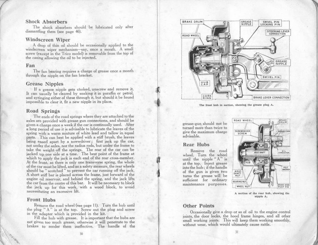
IThe front hoh io ",,"ion. showiog the grea.. pIng A,
BRAKE LEVER CONNECTION
"
grease-gun should not beturned more than twice togive the maximum chargeadvisable.
Front HubsRemove the road wheel (see page 11). Turn the hub until
the plug" A" is at the top. Screw out the plug and screwin the adapter which is provided in the' kit. '
Fill the hub with grease. It is important that the hubs arenot given too much grease, otherwise it will penetrate to thebrakes to render them ineffective. The handle of the
30
l,I
Rear HubsRemove the road
wheel. Turn the wheeluntil the nipple" A" isat the top. Inject greaseinto the hub; if the handleof the gun is given twoturns the grease will besufficient for ordinarymaintenance purposes.
A ,,"'on of the roarhub. sbowlug thenipple A.
Other PointsOccasionally give a drop or so of oil to the engine control
joints. the door locks, the hood frame hinges, and all othersmall working joints, This will keep them working smoothly,without wear, which would ultimately cause rattle.
31
~

"
11I
ELECTRICALEQUIPMENT
Never use the starting motor to propel the car, as it throwstoo severe a strain on the battery and the motor.
If the engine does not start at the first attempt, do not pressthe starter switch until the engine has come to rest. If thisprecaution is not adopted, the starter ring teeth on the flywheelcover, or the starter pinion teeth, may be damaged.
-
'II
Ii
THE lighting and starting units on the Austin Sevencar are arranged for wiring on the single wire system,the return path of the current being provided by the
frame instead of a second wire. It is essential that all unitsare in metallic contact with the frame.
Should difficulties arise that cannot be understood orremedied from the information given below, application shouldat once be made to the Austin Service Department or thenearest service depot of the makers of the equipment (addresson page 51).
DynamoThe dynamo is a simple self-regulating third brush machine.
The only parts calling for any attention are the commutator andbrushes, which are readily accessible whe,! the clip securedcover is removed. The commutator surface must be kept cleanand free from any oil or brush dust. It may be cleaned withordinary soft rag but if it has been neglected use fine glass paper.Blow away any carbon dust, see that the carbon brusbes arewearing evenly and move freely in their holders. To fit a newbrush it is only necessary to release the brusb tag, hold backtbe brush trigger and then withdraw the worn brush from itsholder. The new brush can then be fitted by reversing theabove operations.
The dynamo-bearings are packed with grease before leavingthe works and need very little attention. A few diops ofordinary engine oil, however, may be added through thelubricator near the mounting flange, say every 1,000 miles.The owner is cautioned that far more trouble is causedby excessive oiling than by too little.
Starting MotorThe commutator is accessible on removing the clip secured
cover. The unit requires very little attention beyond keepingthe commutator clean and free from oil, brush dust, etc.. as inthe case of the dynamo. Before starting f~om cold do not neglectthe preliminary precautions that you would observe if starting byhand, such as flooding the carburetter, etc, Remember thatalthough the starter will turn the engine over, however stiff, itis advisable to crank the engine over by hand two or threerevolutions as this will considerably diminish the load for starting.
If the starter pinion jams in mesh with the flywheel ringwhen operating the starting motor switch, usually it can bereleased by putting the gear lever into top gear, and moving thecar bodily backward and forward. If this plan is ineffectualthe starter will have to be dismantled.
Switchbox
The switchbox houses two switches controlling the lightingand charging circuits, a centre.zero ammeter and the ignitionwarning light. The charging switch is also arranged so thatin the" off " position it breaks the ignition circuit, thus obviatingthe necessity of ;, separate switch.
I
I
I
I
I
,,,i
Switch Positions
Each switch has three positions. Left hand switch (I)" OFF" position-dynamo not charging and ignition off.(2) "Summer! Charge" position-ignition operating anddynamo charging with half its normal output. (3) "WinterFull C" position-ignition operating and dynamo chargingwith its full output. Right hand switch (I)" OFF" position-all lamps off. (2)" S " position-headlamps dim and taillamp. (3)" H " position-headlamps bright, and tail lamp.Switching on lamps automatically puts the dynamo onfull charge.
AmmeterThe centre zero ammeter
indicates the rate at which thebattery is being charged or dis-charged under all conditions.For instance suppose 2 amperesare consumed when the dim lampsand tail lamp are switched on,and that the ignition coil takes2 amperes, then if the dynamois generating 7 amperes the meterwill show 3 amperes on the chargeside of the scale. This is thecurrent in excess of the lamp and ignition load that is availablefor charging purposes.
The ammeter gives an indication that the system is function-ing satisfactorily. For example if no reading is given on.thecharge side of the scale when the ignition and charging switchis in the" Winter Full C " position and the car is running atsay 20 m.p.h. with no lights on, then a fault in the dynamocharging circuit is indicated. .
To determine the output of the dynamo, switch off all thelights and add the amount of current used for ignition (about2 amperes at normal speeds) to the reading given on the ammeter.
32 33
,...-
The amount of current used for ignition may be somewhat higherthan the above figure when starting, The ammeter does notindicate the amount of current used by the starter.
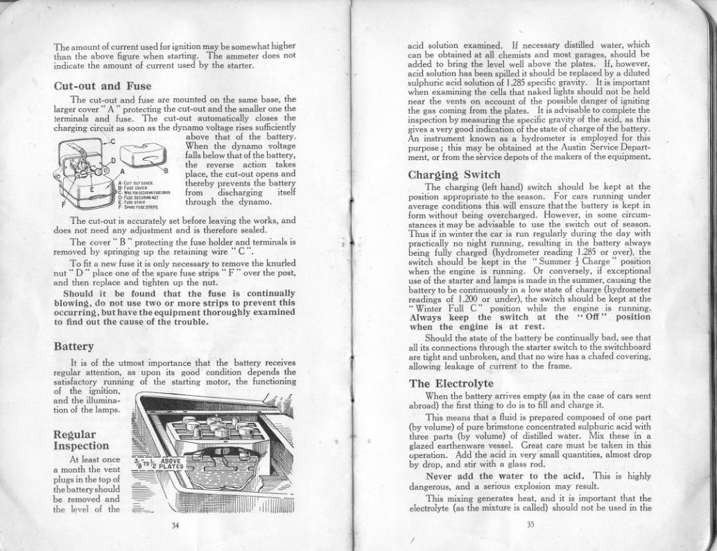
Cut-out and FuseThe cut-out and fuse are mounted on the same base, the
larger cover" A .. protecting the cut-out and the smaller one theterminals and fuse. The cut-out automatically closes thecharging circuit as soon as the dynamo voltage rises sufficiently
- " c above that of the battery.",-" }--
~.' When the dynamo voltage
D ~ CS' falls below that of the battery,- ' the reverse action takes
"QjI ,A B place, the cut-out opens andA'C"-"H"," thereby prevents the battery.-,"","", f d' h
. . Ifc-w,"""""""".~,,,,,.. rom ISC argmg jtseD'",""""."""E-',""'" through the dynamo.,-s"","""""F
The cut-out is accurately set before leaving the works, anddoes not need any adjustment and is therefore sealed.
The cover" B .. protecting the fuse holder and terminals isremoved by springing up the retaining wire" C ".
To fit a new fuse it is only necessary to remove the knurlednut" D .. place one of the spare fuse strips" F .. over the post,and then replace and tighten up the nut.
Should it be found that the fuse is continuallyblowing, do not use two or more strips to prevent thisoccurring, but have the equipment thoroughly examinedto find 'out the cause of the trouble. -
BatteryIt is of the utmost importance that the battery receives
regular attention, as upon its good condition depends thesatisfactory running of the starting motor, the functioningof the ignition,and the illumina-tion of the lamps.
RegularInspection
At least oncea month the v~ntplugs in the top ofthe battery shouldhe removed andthe level of the -"-
34
,
".'
acid solution examined. If necessary distilled water, whichcan be obtained at all chemists and most garages, should beadded to bring the level well above the plates. If, however,acid solution has been spilled it should be replaced by a dilutedsulphuric acid solution of 1.285 specific gravity. It is importantwhen examining the cells that naked lights should not be heldnear the vents on account of the possible danger of ignitingthe gas coming from the plates. It is advisable to complete theinspection by measuring the specific gravity of the acid, as thisgives a very good indication of the state of charge of the battery.An instrument known as a hydrometer is employed for thispurpose; this may be obtained at the Austin Service Depart-ment, or from the service depots of the makers of the equipment,
t
Charging SwitchThe charging (left hand) switch should be kept at the
position appropriate to the season. For cars running underaverage conditions this will ensure thatthe battery is kept inform without being overcharged. However, in some circum-stances it may be advisable to use the switch out of season.Thus if in winter the car is run regularly during the day withpractically no night running, resulting in the battery alwaysbeing fully charged (hydrometer reading 1.285 or over), theswitch should he kept in the" Summer! Charge" positionwhen the engine is running. Or conversely, if exceptionaluse of the starter and lamps is made in the summer, causing thebattery to be continuously in a low state of charge (hydrometerreadings of 1.200 or under), the switch should be kept at the.. Winter Full C" position while the engine is running.Always k€ep the switch at the" Off" positionwhen the engine is at rest.
Should the state of the battery be continually bad, see thatall its connections through the starter switch to the switchboardare tight and unbroken, and that no wire has a chafed covering,allowing leakage of current to the frame.
,",,
The ElectrolyteWhen the battery arrives empty (as in the case of cars sent
abroad) the first thing to do is to fill and charge it.
This means that a fluid is prepared composed of one part(by volume) of pure brimstone concentrated sulphuric acid withthree parts (by volume) of distilled water. Mix these in aglazed earthenware vessel. Great care must be taken in thisuperation. Add the acid in very small quantities, almost dropby drop, and stir with a glass rod.
Never add the water to the acid. This is highlydangerous, and a serious explosion may result.
This mixing generates heat, and it is important that theelectrolyte (as the mixture is called) should not be used in the
35
(

..,..I
RUNNINGADJUSTMENTS
THE adjustments set out below are all that the ownerwill find it necessary to make to keep the car in goodrunning order.
Valve Tappet AdjustmentT0 ~nsure obtaining the full power of the engine. and to
maintair. silence in the valve operation. it is essential to keep thetappets correctly adjusted. To make this adjustment. firstremove the valve cover, turn the engine slowly round with thehand starting crank. Watch each valve open in turn and notethe point at which it stops descending. Now turn the enginehalf a revolution further to make sure that the cam is wellaway from the tappet. There should now be between the valve
stem A and tappetscrew B a clearanceequal to the thick-ness of the thin bladeof the" tappet clear-ance gauge:' If theclearance is otherthan this it can beadjusted by loosen-ing the lock-nut Cand raising or lower-ing screw B, being~areful to tighten up
the lock-nut when the adjustment is completed. A specialspanner is provided in the tool kit for this operation. Checkthis adjustment when the engine is warm.
i;
Cleaning Combustion ChamberTo secure the maximum efficiency from the engine it is
necessary to remove the carbon deposit that will have formed onthe surfaces of the combustion chamber. This should be doneafter about 2.000miles running. When the cylinder head isoff it may be advisable to take this opportunity of grinding-inthe valves, although this will need a longcr time for the workto be carried out. In any case, it is recommended that afterabout 4,000 miles the work of grinding-in the valves should beundertaken.
First drain off the water through cock under the radiator.Detach the top water tube from the head. Disconnect the hightension wires from the sparking plugs. Remove the nutsholding down. the head. Then take hold of the head at each
38
'\1
~
l
end and lift it off. This should be fairly easy to do, withoutdamaging the joint washer, which should, in the ordinary course,be in a condition to be replaced.
Removing the CarbonWhen the head has been removed the valves and tops of
pistons will be exposed to view. All dirt or deposit should beremoved by carefully scraping with a sharp tool. Beforegrinding-in the valves it will be necessary to remove the inletpipe, and exhaust manifold. and carburetter, first turning offthe petrol and uncoupling the pipe under the float chamber,then disconnecting the carburetter control, the air stranglerwire, and the windscreen wiper tubing. The valve cover, with itscork washer, can be removed on undoing the two milled nuts.Each valve spring must be lifted by means of the special toolprovided to allow the split cotter A to come out (see illustration) :then remove the spring. The valve is now free to be rotatedon its seat when the tappet screw has been lowered clear of thestem. After it is cleaned a little grinding compound shouldbe smeared evenly on its face, and the valve rotated backwardsand forwards, advancing it a step at short intervals until thepitting is removed. Care should be taken that none of thecompound enters the cylinders and the valve and seating shouldbe wiped clean after the operation. Note that it is ~ssential foreach valve to be ground-in and refitted on its own seating, asindicated by the number on the valve head. The valves arenumbered from I to 8, starting from the front. It is alsodesirable to clean the valve guides. This can be done bydipping the valve stem in petrol or paraffin and moving it upand down, and round, in the guide until the dirt is removed.Then the valve should be cleaned, and the stem smeared withgraphite grease and re-inserted in the guide; the valve springand cup being fitted up round it. The valve lifter is then usedas before to compress the spring, so that the split cotter can be
39
'.
)
"""I'
I
refitted. The smaller diameter of the complete cotter should beuppermost, and the cotter should be fitted down on to the collarat the bottom of the stem. The grease on the stem will help tohold it in position while the lifter screw is slackened, to allow thevalve cup to come down over the cotter. It is easiest if the endvalves are fitted first, working towards the centre ones. Whenrefitting the manifolds ensure that the joints are good. Thecylinder head joint washer should be replaced, copper sidedownward, with a little graphite grease smeared over each side,to make a good joint and to prevent it sticking when the headhas next to be lifted. When replacing the head take care totighten jhe nuts evenly. Don't forget, "fter replacing thehead, to refill the radiator.
Liftin~ the Cylinder BlockFor access to the pistons (except the piston crowns), and the
connecting rods, or for fitting a new tappet plunger or guide, orvalve guide, it is necessary to lift the cylinder block. The threenuts on the distributor side are easily removed, also the threebarrel nuts on the valve side can be removed without difficultywhen the valve cover has been taken off. For access to thenut at the front of the cylinder block the dynamo and casingwith the fan bracket and fan, must be lifted clear. First pullthe ignition leads and the lead from the coil, from their socketsin the distributor cover. Disconnect the dynamo and theignition control, and remove the fan belt. The casing issecured by three set screws and a nut. With the casingremoved, the front cylinder block nut is accessible. Foraccess to the rear nut of the block, it is advisable tolift the starter:motor and casing, from its mounting over theflywheel. This is done by removing the two set screws,and lifting the casing clear vertically off its positiornng dowel.The cylinder block can be lifted when the lower hose connectionhas been removed. When refitting the starter-motor casing,the larger set screw is required at the nearside of the casing.There is no joint washer between this casing and the crankcase,but paper joint washers are used between the cylinder block andthe crankcase, also under the dynamo casing. These jointsmust be oil-tight. When refitting the cylinder block it isnecessary to use sleeves on the pistons to compress the rings.These piston ring sleeves are among the extra tools obtainablefrom the Service Department of the Austin Motor Co., Ltd.It will be necessary to retime the ignition (page 22) afterre-assembling.
Adjustin~ the BrakesThe hand brake operates on the front wheels and the foot
brake on the rear wheels. They require adjusting when thehand lever can b. ipulled right back to the full travel on therack, and when the pedal can be pushed nearly to the floor-board without either brake holding the wheels. The car should
40
\
- H,'
in this condition, but should beattended to at once.
Access to the handbrakemechanism is through the smallcover in the centre of the car, justbehind the gearbox.
To adjust the hand brake pullthe lever on about one-third of thetotal travel provided by the rack.Now unlock the nut (B) and screwup the brake adjusting screw (A)until the shoes are hard on thedrum. If the brake shoes do notthen rub on the drum, when thelever is right forward, the adjust-ment is correct. See that the screwis locked again by nut (B).
To adjust the foot brake:Under the car and approximatelyunder the foot controls is a wing
nut (C). This mustbe screwed towardsthe front of theengine until thebrakes go full onwhen the pedal isdepressed about 2in.When the pedal isup, the brake shoesshould not rub therear wheel drums inwhich they operate
never be taken out when
Rear Brake CompensationFor compensating,the rear brakes, which may be necessary
after re-!filing the shoes, an individual adjustment for eachof the rear brake cables is provided. A screwed end, to whichthe cable is attached, screws into the front fork-end, whichsecures the cable to the compensating tube lever. By removingthe fork-end from the lever (a pin, secured by a split-pin, holdsit) the fork can be screwed further on or off the screwed cableend to effect the compensation. The cable must not betwisted while this is being done. To test whether both brakesengage equally at the same time, jack-up the back axle, and
. with the brake pedal pressed down, turn each wheel by handto judge the braking effect.
Trackin~ AdjustmentOne of the causes of premature tyre wear is the front wheels
being out of track. The wheels, if they are correctly trackingshould not be parallel, but should be k in. closer between the
41
)

Irims in front of the axle than they are"behind. This diflerence,or " toe-in" as it is called, allows for working clearances of thesteering connections, and any slight spring of the parts, so thatwhen the car is running the wheels are as near parallel aspossible. If on checking this difference, it is greater or smallerthan ~in. the tracking should be adjusted. This is not difficult toeffect. It is necessary to remove the cross tube lever, on the nearside, from the swivel axle. It is secured by a nut on the frontof the swivel axle, under which there is a spring washer. Withthis done, the steering cross tube is freed at the near side forthe adjustment.. On the clamping bolt of the steering arm jawbeing slackened, the jaw can be screwed further on, or off, thecross t.lbe, for so many complete turns, as may be necessary.This movement will enable the correct adjustment to be attained;then the clamping -bolt is re-tightened. On refitting the crosstube lever to the axle, tighten the nut securely, with thespring washer under it. This, as well as the steeringadjustment described below, is one of the adjustments whichit is advisable to leave to the Austi'; agent to effect, who isproperly equipped for the work.
Adjustment of SteeringIf after continual use slackness should be felt in the steering,
two adjustments are available :- To take up the play in thecolumn, loosen the nut which tightens the bracket supportingthe steering outer column to the instrument board, unscrewlocking peg (A) and clamping bolt (B), then turn the sleeve (C)with tbe special spanner provided for the purpose, until theplay has been removed. Do not screw the sleeve in too tight
/
42
\
'"
or the steering will then become stiff. Having adjusted thesleeve correctly, screw in the locking peg so that it enters oneof the slots of the sleeve, tighten up the clamping bolt, and thesupporting bracket to the instrument board.
To take up the clearance between the worm .and wormwheel, due to wear, remove the locking plates and slacken thethree nuts (D) holding the cover (E) to the worm casing, thenturn adjusting nut (F) so as to slightly draw the cover in thedirection of the worm. Care must be taken that the worm wheelis not brought too tight into mesh with the worm or it will makethe steering exceedingly hard and stiff. Having made theadjustment be sure and tighten up the three nuts (D) and lockthem with the locking plates.
Should it-be desirable to remove the steering worm wheelfrom the casing, it is only necessary to slacken the adjusting nut(F) and remove the three nuts (D) when the cover (E) can bewithdrawn together with the worm wheel and steering arm. Thesteering column (H) with control rods can be withdrawn by firstremoving control levers (K), and nut (L), then slackening lockingpeg (A), and clamping bolt (B), and unscrewing the sleeve (C).These adjustments, again, should be left to an Austin agent toeffect.
Re-lining the BrakesTo - re-line the brakes it is necessary first to remove the
wheel, and then the brake drum, by unscrewing the threescrewdriver screws which secure it to the hub: and. before the
".
shoes can be removed for re.lining, the hub and wheel bearingmust be extracted. For this a special hub extractor is suppliedin the tool kit. -
43
)
-~
Rear BrakesFor the rear wheel brakes (see illustration on page 31)
remove the axle shaft nut, having first taken out the split pin,and extract the outer portion of the hub by screwing the extractoron the screwed end, and turning the extractor bolt which bearson the end of the axle shaft. Remove the key from its keywayin the axle shaft. Next remove the bearing nut, having knockedback the tang of the washer locking it, and prise the inner portionof the hub or felt housing together with felt packing and bearing,off the end of the axle casing. Do not damage the paper washerbetween the-hub and the felt housing faces, as it is importantto make a good joint on reassembling, to prevent the hublubricant penetrating to the brake. If this inner portion of thehub does not easily come off the axle casing, the outer halfshould be refitted as closely as possible, using the wheel nutsto draw the two halves together. Then use the hub extractora second time, and so remove the hub together with bearing andpacking. The brake shoes can now be pulled off the cam andpivot pin and the springs unhooked. The old linings can thenbe detached by punching or drilling out the rivets.
The brake linings should be clamped to the shoes while theriveting is in progress, as it is essential that they should beddown on the shoes over their whole area.
removal. Now replace the outer portion of the hub ?nd pullit up to its original position by the wheel nuts, as in the caseof the rear wheel. By means of the extractor draw off the hubwith its bearing and packing. The brake shoes are left clearfor removal. On reassembling remember to fit a new split pinthrough the axle and nut; there is a hole in the end of the hubthrough which the pin can be inserted.
lt is always necessary to re-line all four brake shoes on theone axle at the same time, and after the re-lining it may benecessary to slack off the brake adjustment before the brakedrum can be replaced.
After re-lining the brakes make sure that the hubs containsufficient lubricant, re-adjust the brakes and compensate them,if necessary (see pages 40 and 41).
Adjusting Austin Front Shock AbsorbersThe shock absorber is set to a certain initial tension before
it leaves the factory, and no change in this adjustment should benecessary for a very considerable time.
Re-adjusfment may only become necessary after severalthousand miles of car travel, and should be made only when thespring movement seems too free. It should be noted that,normally, the full benefit of the shock absorbers will not be feltwhen the car is travelling at low speeds, as under these con-ditions the spring movement is very limited, but, as the speedincreases their effect becomes more pronounced, especially overbad roads when the spring action is most severe. Testingshould, therefore, be carried out at comparatively high averagetouring speeds and adjustment made to suit these conditions.
The frictional resistance required to effectively control theaction of the springs is comparatively small, and care should betaken not to alter the pressure, when adjusting, more than isabsolutely necessary in order to obtain the desired results.
For fast sporting cars and for road and track racing, aconsiderable increase in pressure may, of course, be required.
When adjustment does become necessary, carefully note theriding qualities of the car, and if the spring action seems tooretarded or stiff, reduce the frictional resistance of the shockabsorbers by turning the centre adjusting nut to the left, orcounter.clockwise, after slackening the lock nut. If the springaction seems too free, increase the frictional resistance byturning the adjusting nut to the right, or clockwise. Afteradjusting, tighten the lock-nut.
Careful adjustment in this manner will produce an idealcondition. Th, spring will still have the required amount offlexibility for easy riding, but spring vibration will be reducedto a minimum and violent rebound effectively eliminated.
The rear Austin shock absorbers do not require adjustment.
ReassemblingTo reassemble, replace the shoes with their springs on the
cam and pivot pin. Replace the inner portion of the hub or felthousing with the bearing and packing on the axle casing end,and push up home by tightening the bearing nut, which mustbe locked by the locking washer in the same way as beforedismantling. Replace the paper joint washer on the felt housingface, insert the key in the shaft, push the hub over the axle' shaft,on the key, and draw it up to the felt housing by the wheel nutson their studs. When the joint faces of the hub and the felthousing are together replace the axle nut and tighten securelyup to the hub boss. Remember to inset! the split pin through the nut.Then remove the wheel nuts from the hub, fit the brake drum,and insert and tighten the three screwdriver screws.
~
Front BrakesFor the front brakes (see illustratio'n on page 31) the opera-
tion is somewhat similar. Having removed the wheel, and thebrake drum, secured by the three screws, remove the' hub cap,and screw on the extractor in its place. Before proceedingfurther, remove the plug (A) from the hub, or unsc" w it for aboutthree turns; otherwise it will foul the outer hub bearing whenthe hub is being extracted. Draw off the outer portion of thehub. The axle nut and split pin will now be accessible for
44 45
( J

\I
HOODCARECleaning the Shock AbsorbersPeriodically-especially in wet weather when much mud is
thrown on to them-the large end of the shock absorbers shouldbe taken apart, by withdrawing the centre bolt, and thoroughlycleansed. The centre pin and washers should be well lubricated,and a thin smear of grease, used with discretion on the frictionsurfaces will prevent the entry of moisture, and so prevent theshock ;bsorbers becoming tight and inoperative,
If this precaution is not adopted, the shock absorbers areliable to become tight-when an excessive load is thrown on thepins and bushes at the end of the arms, which will cause rapidwear. In addition, great strain is imposed on the bracketholding the shock absorber to the frame.
THEOFLowering the Hood
To lower the hood, first release it from the pillars of thewindscreen, push the side screens inwards so that the rubberbuffers fixed near the top of the division on the side screensclear the iron framework of the hood,
Now push thehood straight up
and back from the rfront and breakthe joint of theiron framework.see illustration,
The pictureshows very clearlythe commence-ment of the" con-certina" move-mentwhich beginsthe actual lower-ing of the hood.
The hocd willthen collapsetowards the backof the car. Pullthe folds out until.they lie in one bigfold over the back of the car. see below; secure the two rearwindow fasteners, on to the studs on the back of the body, andsecure the hood frame with the clip on either side. Ensure that the
folded frame rests inthe support near theforward end of th~lowered upright thatpivots on the body,
Now fold thematerial back care-fully, seeing that theedges are evenlyplaced, turn them in,;either side-see illus-trationbelow-orun-der and put the coverin position over all.
Secure the coverby the straps, oneeach side, and thetwo fasteners on theback of the body.
I,
Clutch SlipSome drivers are inclined to use the clutch instead of
changing down to a lower gear, particularly when they arealmost at the top of a hill and it is only necessary.to changedown for a few yards. Foot pressure is applied to the clutchto create a certain amount of slip (see page 10). This highlypolishes the frictional- surfaces and will eventually be thecause of persistent slip; finally in addition to burning out thefabric rings, probably also distorting the centre plate andmaking renewal of this essential.
Sometimes clutch slip is due to oil penetrating to the clutchfrom the engine or gearbox. This results from over-oiling ofeither or both of these units (pages 27 and 28). If the inspectionplate over the Clutch casing is removed petrol can be syringedon the clutch plate to wash off the oil, so that the clutch regainsits frictional characteristics. The petrol and oil will drain awaythrough a hole in the casing under the flywheel.
When injecting the petrol have the engine turned so thatthe plate is properly washed and the petrol and oil are givenan opportunity to drain away, also push the clutch out and letit in by the pedal so that the petrol is given a washing action.Do not replace the inspection plate, until the oil and petrolhave had sufficient time to evaporate off.
After this operation it is advisable to lubricate thedeclutching levers at their pivotting points and the clutchwithdrawal collar (page 28) as the lubricant in these membersmay have been removed by the 'petrol.
There is no adjustment necessary for the clutch.
~
~
J
jj!I1I I.
JFan Adjustment
Release the clamping pin nut on the fan bracket and thenturn the spindle, which is in the form of a crank, until thenecessary tension is obtained in the fan belt.
4746
),
- "Raising the Hood
To raise the hood. remove the cover, release the clip. andunfold the hood material. Lift the top hood stick vertically,
holding the metal side- I;
~
strip of the hood framenear the hinge. If thefront hood stick is then J Ipushed forward and the '
metal strips are pulledback, to straighten thehinge. the whole hoodcan be dropped for-ward and secured in position to the windscreen.
account should metal polishes be used, as are sometimesadvertised for cellulose. It has be~" found that the more thesurface of the cellulose finish is rubbed by the polishingcloth, the smoother and more lasting is the lustre imparted.
~
STORING THE CARShould the car be laid up in the garage for long periods. the
fuel and water should be drained off and the batteries removed,and weight taken off the tyres.
Care of the HoodCare should be taken in folding down the hood to see that
the original folds are used. Should the car have been used inwet weather leave the hood up to dry. Never fold it when wet.
The joints will be stiff when new; they are intentionallymade so, in order that they will not rattle when they haveworked in. Each joint and hinge should have a drop of oiloccasionally; this will ease the movement. The best dressingfor the Austin Seven hood is good quality black boot polish.Brush it in, particularly round the seams. and rub it well so thatthe polish is forced into the gram of the material to keep it
.,waterproof.
THE TYRESTyre Pressure
The minimum pressure at which both ront and back tyresshould be inflated is 20 lbs.
Should. due to wear or other causes. the steering at allYtime develop a tendency to wander or show signs of wobble.this pressure should be increased. It is important that bothfront tyres should be kept at the same pressure. In any eventthere is no reason why the pressure should not be more thanthe mmimum figure given, as some drivers prefer their tyresharder than do others.
As tyres form such a large item in the running costs of a carit is advisable to give them periodical examination and attention.
A cursory glance should be given daily to see that none ofthe tyres is unduly slack, and a weekly test with a suitable gaugeshould be made to verify the pressures. Occasionally examinethe tyre treads for cuts; bad cuts should be vulcanized.
Tyre WearBecause of the turning in of the wheels towards each other
at their lowest point. it has been found that the front side tyrewears at its outer edge. The camber of the "road tilts the cartowards the left, and the tyres are distorted. It is in the actionof recovering their correct shape, 'immediately after contactwith the road, that they suffer abrasion. made more damagingbecause the gritty substances now used on tarmac roadaccumulate on the near side and the wheel is running in thisgrit for most of the time it is on the road. So change your frontwheels over and thus equalize the wear between the tyres.When both tyres have become worn on the outside edge, changeover the back wheels with the front wheels. Subsequently thetyres can be turned round, bringing the least worn edge to theoutside. If the front tyres should show premature wear atany time suspect the trackmg of the front wheels. Have itchecked, to see if it is correct. and, if necessary, adjusted (seepage 41).
"';c-
CARE of the BODYWORK
FOR the car to look well and keep its beauty and smartappearance, the body must be given its shar" of attention;it must not be neglected.
WashingThe cellulose (or fabric) finish of the car is easily cleaned
and polished. In summer weather when the car is only dustythe dust can be .lightly. flicked off without water and there isno risk of damaging the finish. When the car is muddy, washoff well with clean running water. Remove any grease or tarsplashes with petrol. Don't use the same sponge and cleaningcloths for the chassis and springs and other greasy parts asare used for the coachwork.
PolishingDry off and then polish with one of the special polishes now
marketed. (polish is not necessary for the fabric bodies exceptat infrequent intervals. Then an ordinary wax polish can beused, only sparingly applied.) Such preparations impart abrilliant surface and preserve and beautify the body. On no
48 49
., )
'\
( 'rOOLSWITH
SUPPLIEDTHE CAR
AUSTIN SEVEN EQ UIPMENT
* in. and f. in. box spanner. Tool wrap.
i in. and i in. box spanner. Sparking.plug box spanner Xf.r in. and * in. double open. and tommy bar.
end spanner. B f d h bl h I-'- . d 3 race or etac a e w ee s... in. an "in. double open. T I .-
yre ever. "end spanner. T-". . d J.' d bl yre pump.
.. m. an '2m. ou e open. L'
f. .
k.
h h dl vd I tmg lac. WIt an e. "
en spanner.Ad
'
bl 4 . Screwdriver.Justa e spanner, m. .
Carburetter jet key. Sparkmg plug and tappetHub.cap and steering column clearance g~uge.
sleeve spanner. Crease gun wIth adapter.Ignition spanner. Valve.spring lifter:Tappet adjusting spanner. Combination pliers.Spanner for monobloc nuts. Hub extcactor. X
A spare cylinder.head joint washer is also supplied. K
T HE Austin Motor Co, Ltd., accept no liability underthe terms of their Warranty for Tyres, Speed-ometers, or the Electrical Equipment, or other
goods, including Coachwork, not of tbeir ownmanufacture.
All claims relating to any of these parts or fittingsor orders for repairs to them, should be addressed totheir manufacturers,
For owners' information we give below the namesand addresses of the manufacturers, or suppliers of theequipment fitted on the Austin Seven,
IMPORTANTWhen claims under guarantee are being made, it is
absolutely necessary to quote the type and number ofthe car, and the commissioning date.
Electrical and Ignition Equipment, Lampsand Batteries {!
" Lucas " Joseph Lucas, Ltd., Creat Hamptonand Street, Birmingham and Dordrecht
"C.AY" Road, Acton Vale, London, W.3.
~.
THE AUSTIN MAGAZINEWindscreen
"Trico"" Folberth "
WiperA. Rist, Ltd., Waveney Works, Lowestoft.C. C. Vokes & Co., Ltd" 95.97, Lower
Richmond Road, Putney, London,S.W.15.
A high-class monthly motor journal of wideappeal and ,~pecialinterest to the Austin owner
SUBSCRIPTION 5/- per annum (postfree)
Grease Gun"Enots" Benton and Stone, Ltd., Bracebridge
Street, Birmingham.
4d, MONTHLY-From any Bookstall or Newsagent Speedometer"Smith" S. Smith and Sons (MA), Ltd., Crickle.
wood Works, London, N.W.2.
Send your Subscription NO W-
"THE AUSTIN MAGAZINE,"SUBSCRIPTION DEPARTMENT,
LONGBRIDGE, Birmingham.
Bodies and" Cordon
England"" Mulliner "
"Startin"
FittingsCordon England, Ltd., Palace of Industry,
Wembley,Mulliners, Ltd., Bordesley Creen Road,
Birmingham.Thomas Startin, Junr., 71, Aston North
Road, Birmingham.
5150
~
" I