Handbook2 Handbook Importing 3D Models Defining the views Setting the lighting Assigning materials...
59
Handbook
Transcript of Handbook2 Handbook Importing 3D Models Defining the views Setting the lighting Assigning materials...

Handbook
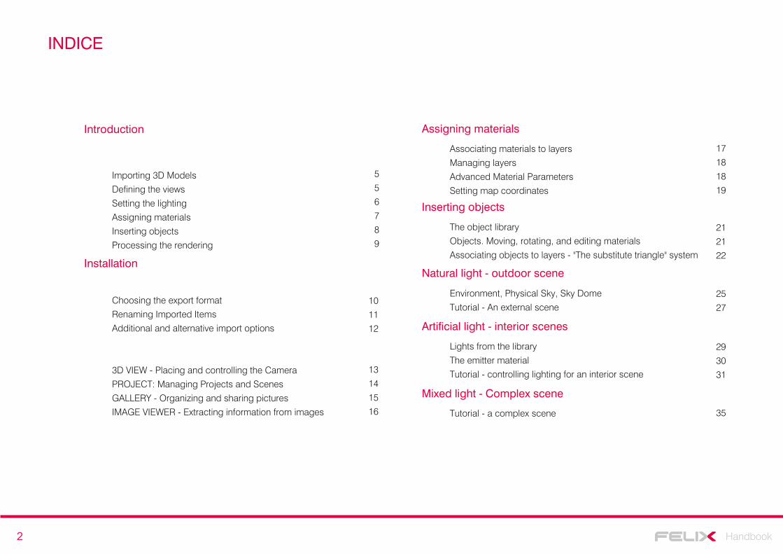
2 Handbook
Importing 3D Models
Defining the views
Setting the lighting
Assigning materials
Inserting objects
Processing the rendering
Introduction
5
5
6
7
8
9
Installation
Choosing the export format
Renaming Imported Items
Additional and alternative import options
10
11
12
3D VIEW - Placing and controlling the Camera
PROJECT: Managing Projects and Scenes
GALLERY - Organizing and sharing pictures
IMAGE VIEWER - Extracting information from images
13
14
15
16
Associating materials to layers
Managing layers
Advanced Material Parameters
Setting map coordinates
Assigning materials
17
18
18
19
The object library
Objects. Moving, rotating, and editing materials
Associating objects to layers - "The substitute triangle" system
Inserting objects
Environment, Physical Sky, Sky Dome
Tutorial - An external scene
Natural light - outdoor scene
Lights from the library
The emitter material
Tutorial - controlling lighting for an interior scene
Artificial light - interior scenes
Tutorial - a complex scene
Mixed light - Complex scene
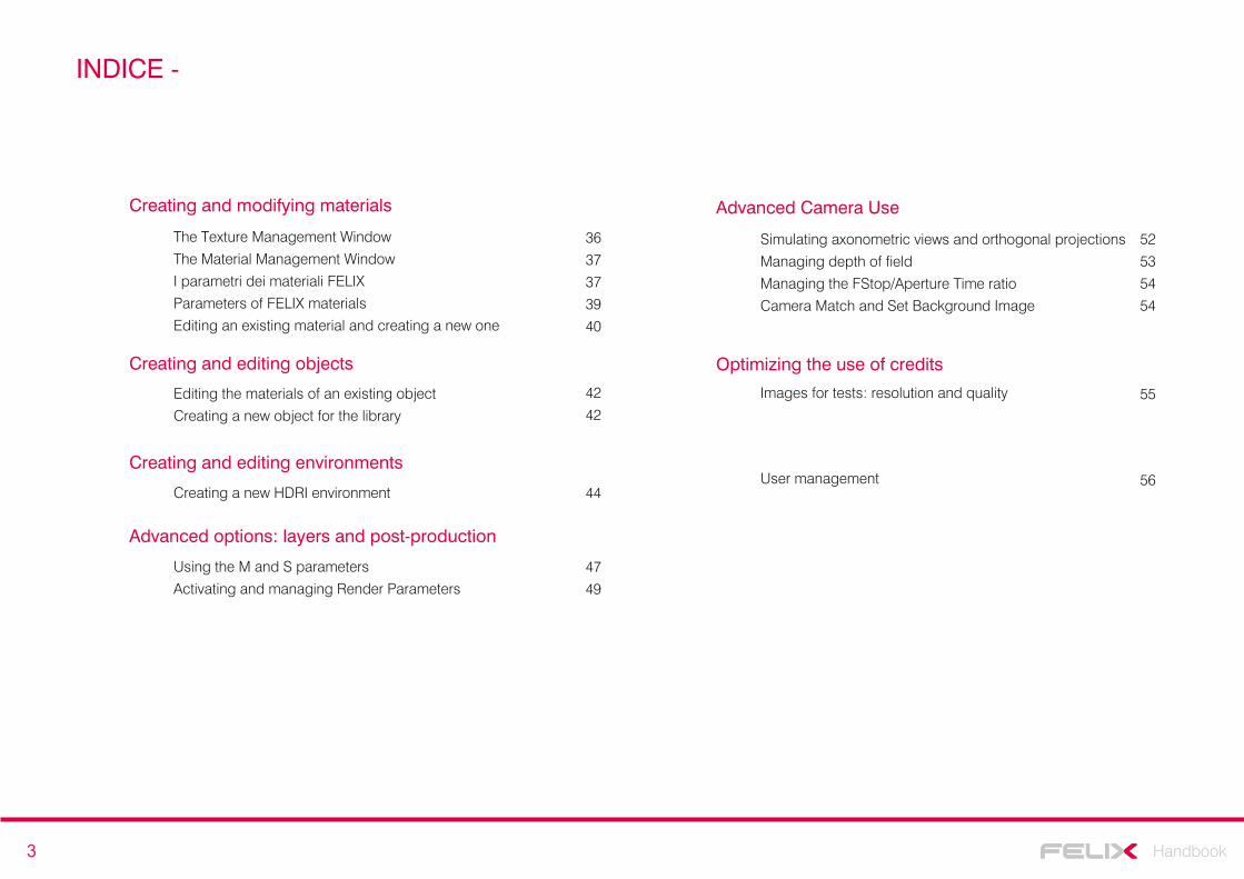
INDICE
21
21
22
25
27
29
30
31
35
3 Handbook
Simulating axonometric views and orthogonal projections
Managing depth of field
Managing the FStop/Aperture Time ratio
Camera Match and Set Background Image
Advanced Camera Use
The Texture Management Window
The Material Management Window
I parametri dei materiali FELIX
Parameters of FELIX materials
Editing an existing material and creating a new one
Creating and modifying materials
Editing the materials of an existing object
Creating a new object for the library
Creating and editing objects
Creating a new HDRI environment
Creating and editing environments
Using the M and S parameters
Activating and managing Render Parameters
Advanced options: layers and post-production
Optimizing the use of credits
INDICE -
42
42
44
36
37
37
39
40
52
53
54
54
47
49
Images for tests: resolution and quality 55
User management 56
4 Handbook
Introduction
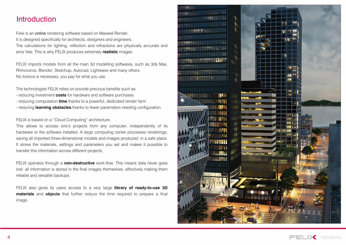
Felix is an online rendering software based on Maxwell Render.
It is designed specifically for architects, designers and engineers.
The calculations for lighting, reflection and refractions are physically accurate and
error free. This is why FELIX produces extremely realistic images.
FELIX imports models from all the main 3d modelling softwares, such as 3ds Max,
Rhinoceros, Blender, Sketchup, Autocad, Lightwave and many others.
No licence is necessary, you pay for what you use.
The technologies FELIX relies on provide precious benefits such as:
- reducing investment costs for hardware and software purchases
- reducing computation time thanks to a powerful, dedicated render farm
- reducing learning obstacles thanks to fewer parameters needing configuration
FELIX is based on a “Cloud Computing” architecture.
This allows to access one’s projects from any computer, independently of its
hardware or the software installed. A large computing center processes renderings,
saving all imported three-dimensional models and images produced, in a safe place.
It stores the materials, settings and parameters you set and makes it possible to
transfer this information across different projects.
FELIX operates through a non-destructive work-flow. This means data never goes
lost: all information is stored in the final images themselves, effectively making them
reliable and versatile backups.
FELIX also gives its users access to a very large library of ready-to-use 3D
materials and objects that further reduce the time required to prepare a final
image.
5 Handbook
Quick Start
The FELIX work-flow is simple and straightforward.
The first step is to import the 3d model. You can then define the views, set the
lighting, assign the materials and add any final touches, after which the final render
can be calculated.
Importing the 3d Models
FELIX imports three-dimensional models from all major modeling software.
The files must first be saved in one of these formats:
3ds, dae, dxf, fbx, lwo, o3d, obj.
In FELIX, all the work is organised by project. Within each project you can save
different files. For example, if you are working on images for a home, you might call
the project "Home X" and individual files containing specific 3d models, "external",
"indoor", "garage" etc…
In FELIX your render job is simply titled Project and the individual files with their
relative 3d models are called Scenes.
To import 3d models simply click on the Import menu and select the file you want. By
doing so, the following screens will appear.
Import management and Project folderOptions to rename imported objects
The first screen displays all the layers or elements contained in the file. Here you can
choose whether to import the objects by keeping the name given to them in the
modeling software or by grouping them based on the membership layer or the
assigned material.
On the next screen, however, it is necessary to define the name of your current
project (Project) within which all of the models will be loaded (Scenes).
Defining the viewsWhen the import procedure is complete, the scene is displayed as a 3D object in the
3D VIEW window and as a file in the PROJECT window.
At this point one must decide what to frame.
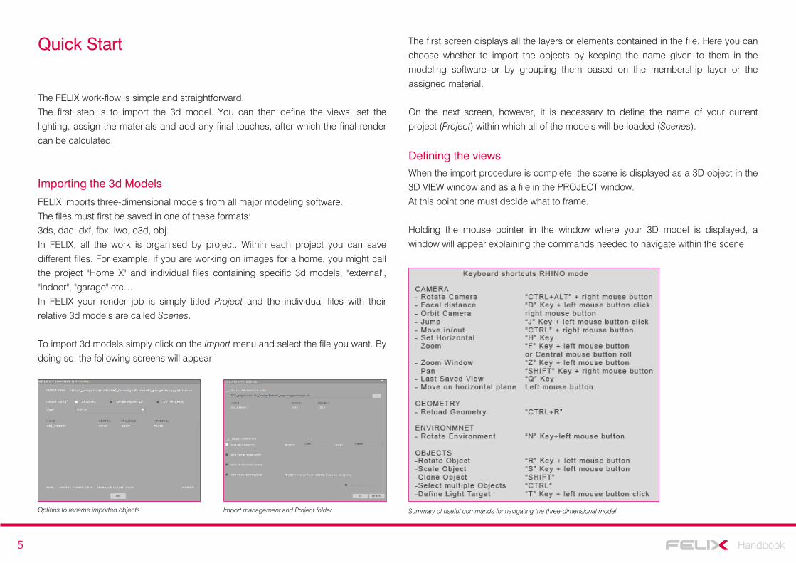
Holding the mouse pointer in the window where your 3D model is displayed, a
window will appear explaining the commands needed to navigate within the scene.
Summary of useful commands for navigating the three-dimensional model

6 Handbook
To better understand the movements of the camera, it may be useful to describe the operation of some commands in detail:Rotate: rotates the camera in all directions. It's like turning your head whilst remaining still.Orbit: rotates the camera using the mouse pointer as the center.Move in / out: Moves the camera along the axis of the lens.Move on horizontal plane: it corresponds to walking inside the scene.
NOTE
The 3D VIEW window displays all the parameters of FELIX Camera that match your
current viewpoint. It behaves like a real Camera: using the commands and
switching on the sliders to the right of the parameters, you can set the focal point,
focal length, aperture, stop time, aperture time and lens decentralization (V Offset).
FELIX’s camera will produce brighter or darker images depending on the exposure
time you set. If the images processed are too dark or too light, all you have to do is
increase or decrease the exposure time without having to change the intensity of
the light source.
After selecting the first shot, you can define the image quality that will be calculated
by increasing or decreasing the number of squares in the center of the View
La gestione delle inquadrature nella colonna ViewI parametri della Camera di FELIX
This parameter only changes the amount of noise inside the image, affecting the
cost and the computation time.
By double-clicking on the two numeric values next to the squares, you can change
the pixel resolution in the image.
The indicator to the right of each View shows the cost in credits of computing the
image (default 1 credit).
For your initial tests, it is best to set the quality to a single frame and reduce the size
of the image to a maximum (approximately 550x275 pixels for the 2:1 aspect ratio).
Setting the lightingAfter selecting the frame, the next step is to set the lighting.
FELIX provides a wide range HDRI images to illuminate your scenes. To assign an
environment to a view, simply open the ENVIRONMENT LIBRARY SETUP window by
right-clicking on a view and selecting ENVIRONMENT and ENVIRONMENT LIBRARY
sequentially.
After selecting an image from one of the different categories, click OK to use it within
your scene.
The selection window with the HDRI images to use as Environments
7 Handbook
By holding down the N key and the left mouse button you can rotate the spherical
image that will illuminate your scene.
To easily locate the position of the light source, and therefore the direction of light, it is important to observe how shades are cast onto the walls of your three-dimensional model. We suggest rotating the environment to fully illuminate the walls in front of the House. This means that the sun is right behind you. By looking at the wind icon you can rotate the environment to achieve the desired lighting.
NOTE
Assigning materials
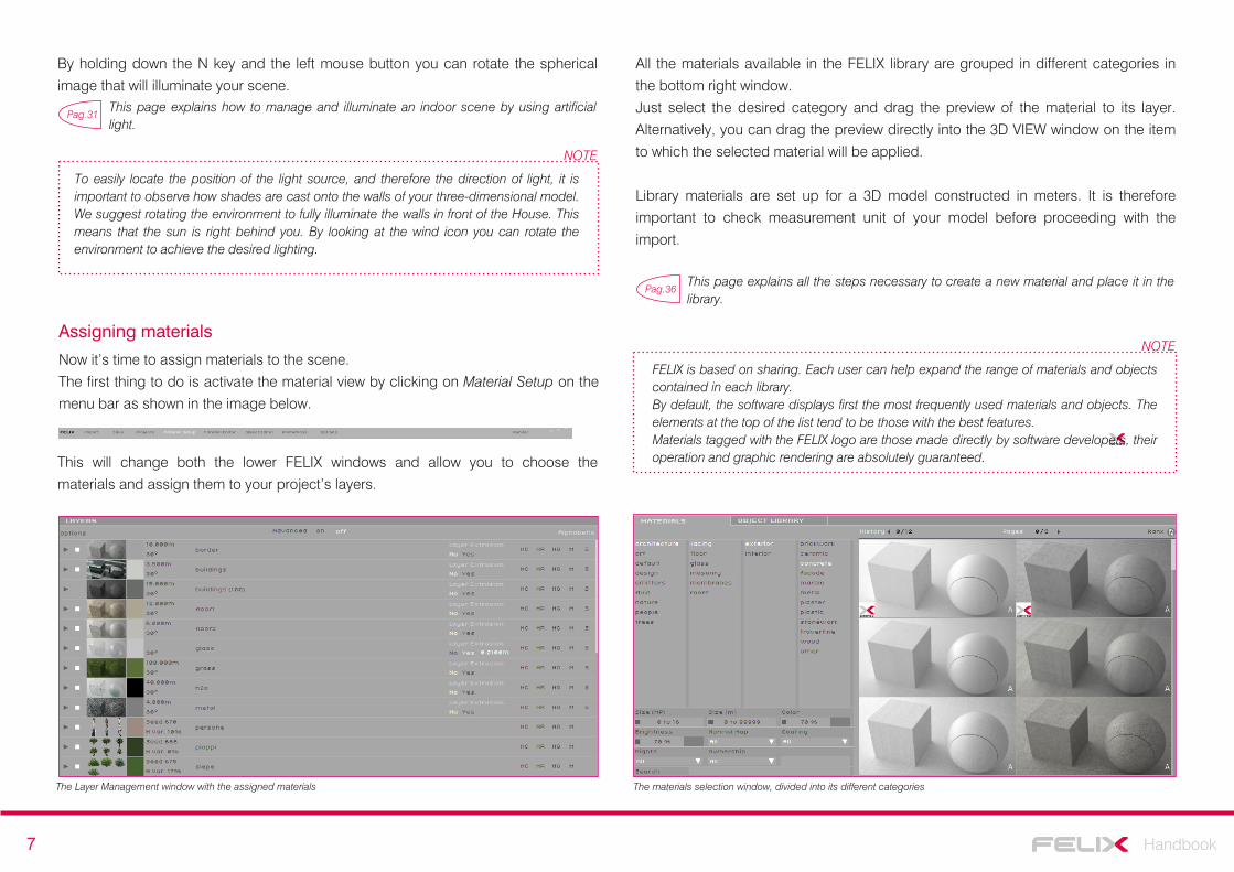
Now it’s time to assign materials to the scene.
The first thing to do is activate the material view by clicking on Material Setup on the
menu bar as shown in the image below.
The materials selection window, divided into its different categories
This will change both the lower FELIX windows and allow you to choose the
materials and assign them to your project’s layers.
The Layer Management window with the assigned materials
All the materials available in the FELIX library are grouped in different categories in
the bottom right window.
Just select the desired category and drag the preview of the material to its layer.
Alternatively, you can drag the preview directly into the 3D VIEW window on the item
to which the selected material will be applied.
Library materials are set up for a 3D model constructed in meters. It is therefore
important to check measurement unit of your model before proceeding with the
import.
Pag.31This page explains how to manage and illuminate an indoor scene by using artificial light.
Pag.36This page explains all the steps necessary to create a new material and place it in the library.
NOTE
FELIX is based on sharing. Each user can help expand the range of materials and objects contained in each library.By default, the software displays first the most frequently used materials and objects. The elements at the top of the list tend to be those with the best features. Materials tagged with the FELIX logo are those made directly by software developers, their operation and graphic rendering are absolutely guaranteed.
8 Handbook
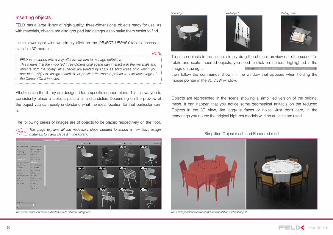
Inserting objects
FELIX has a large library of high-quality, three-dimensional objects ready for use. As
with materials, objects are also grouped into categories to make them easier to find.
In the lower right window, simply click on the OBJECT LIBRARY tab to access all
available 3D models.
The object selection window divided into its different categories
To place objects in the scene, simply drag the object's preview onto the scene. To
rotate and scale imported objects, you need to click on the icon highlighted in the
image on the right:
then follow the commands shown in the window that appears when holding the
mouse pointer in the 3D VIEW window.
Objects are represented in the scene showing a simplified version of the original
mesh. It can happen that you notice some geometrical artifacts on the reduced
Objects in the 3D View, like jaggy surfaces or holes; Just don't care, in the
renderings you do the the original high-res models with no artifacts are used.
Simplified Object mesh and Rendered mesh
FELIX is equipped with a very effective system to manage collisions.This means that the imported three-dimensional scene can interact with the materials and objects from the library. All surfaces are treated by FELIX as solid areas onto which you can place objects, assign materials, or position the mouse pointer to take advantage of the Camera Orbit function.
NOTE
All objects in the library are designed for a specific support plane. This allows you to
consistently place a table, a picture or a chandelier. Depending on the preview of
the object you can easily understand what the ideal location for that particular item
is.
The following series of images are of objects to be placed respectively on the floor,
The correspondence between 3D representation and real object
Floor objet Wall object Ceiling object
Pag.42This page explains all the necessary steps needed to import a new item, assign materials to it and place it in the library.
9 Handbook
Processing the rendering
The last step is to start rendering.
To start processing the image, you must move back onto the Project menu:
A simple click on the grey dart, on the right of each single View, will fit your frame into
the rendering queue.
Otherwise you can simply drag the views from the View column to the Render Queue
column.
To start the actual rendering operation, press the Render button on the top right of
the menu bar.
FELIX allows you also to include a series of different shots belonging to the same
project, or even to different Scene or Project, into the same rendering queue.
This feature allows you to easily plan and organize your work. After the views have
been sent to the computation centre, you can even turn off your computer, as the
rendering process runs remotely. When you reopen the scene, FELIX will report the
presence of new images ready to be downloaded.
To optimize your use of credits and reduce your computation time, it might be helpful
to follow these guidelines to control image quality:
- Quality 1: Drafts
- Quality 2: External images with daytime illumination
- Quality 3: Internal and external shots in the night or evening
- Quality 4: poorly lit interior shots
It is good practice to start by rendering low quality images without materials. This allows you to concentrate exclusively on lighting.Once you are happy with the lighting, you can better evaluate the overall result by adding all the materials and objects.Only at this point is it convenient to start computing the high resolution image.This process allows greater control of both end result and cost.
NOTE
10 Handbook
Installation
To begin using FELIX, you need to download the right installation file for your
operating system. The address to download the individual files is: http://
www.felixrender.com/download-felix
FELIX needs to archive some files within the computer you are using, therefore it is
useful to provide the software with all the necessary rights to access the hard disk
without restriction.
Windows Vista, Windows 7, and Windows 8 impose restrictions on accessing the
Program folder, so the installation file is programmed to extract the data that is
needed to run the software directly in the root of disk C at this location: C:
\StackSoftware\Felix.
FELIX communicates with the network through the 80 and 7975 Internet ports. It is
therefore important to verify, especially if you are connecting from a public network,
that these ports are open at the output.
For a proper configuration, refer to the firewall documentation or contact your system
administrator.
If, for any reason, it’s too risky to open output port 80 and 7975 to any IP, it is
possible to restrict access to this IP list:
79.136.118.194
79.136.118.195
79.136.118.196
Importing
As already mentioned, FELIX imports three-dimensional models from all major
modeling software.
Remember, though, that the files to be imported must first be saved in one of these
formats: 3ds, dae, dxf, fbx, lwo, o3d, obj.
To make the process even clearer, the various import types will be described by
differentiating them based on the extension of the exported file and the software used
to model.
What should you export, 3ds, dae, dxf, fbx, lwo, o3d or obj?Each of these extensions communicates slightly differently with FELIX. It is therefore
useful to know the characteristics of each one, in order to choose which best suits
the various situations.
The main distinction lies in how the three-dimensional elements will be grouped into
FELIX layers and how they will be named.
In fact, the layers are the main tool for assigning materials in FELIX. Individual three-
dimensional elements have to then be considered in relation to the material that will
be applied to them.
This avoids working on FELIX with a long and sluggish list of layers with randomly
assigned names.
The workflow used during modeling will also affect the choice of the exported file
extension.
Some extensions allow you to combine in a single FELIX layer all the objects that
have already been assigned the same material in the modeling software. Others
gather objects depending on the membership layer. Others still, leave the names
assigned to the three-dimensional elements, unchanged.
An additional set of data that can only be archived by some extensions, is that
relating to the mapping coordinates assigned to the different objects.
11 Handbook
3ds
dae
dxf
fbx
lwo
o3d
obj
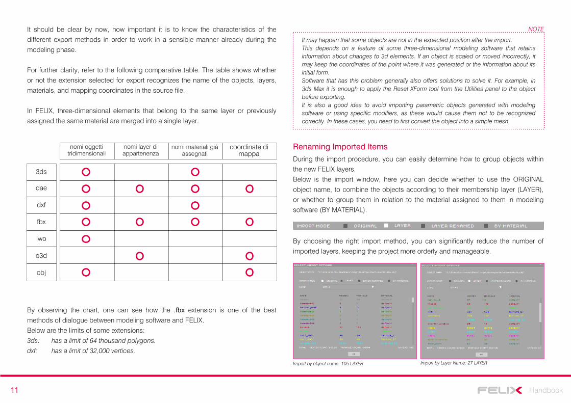
nomi oggetti tridimensionali
nomi layer di appartenenza
It should be clear by now, how important it is to know the characteristics of the
different export methods in order to work in a sensible manner already during the
modeling phase.
For further clarity, refer to the following comparative table. The table shows whether
or not the extension selected for export recognizes the name of the objects, layers,
materials, and mapping coordinates in the source file.
In FELIX, three-dimensional elements that belong to the same layer or previously
assigned the same material are merged into a single layer.
coordinate di mappa
nomi materiali già assegnati
By observing the chart, one can see how the .fbx extension is one of the best
methods of dialogue between modeling software and FELIX.
Below are the limits of some extensions:
3ds: has a limit of 64 thousand polygons.
dxf: has a limit of 32,000 vertices.
It may happen that some objects are not in the expected position after the import.This depends on a feature of some three-dimensional modeling software that retains information about changes to 3d elements. If an object is scaled or moved incorrectly, it may keep the coordinates of the point where it was generated or the information about its initial form.Software that has this problem generally also offers solutions to solve it. For example, in 3ds Max it is enough to apply the Reset XForm tool from the Utilities panel to the object before exporting.It is also a good idea to avoid importing parametric objects generated with modeling software or using specific modifiers, as these would cause them not to be recognized correctly. In these cases, you need to first convert the object into a simple mesh.
NOTE
Renaming Imported ItemsDuring the import procedure, you can easily determine how to group objects within
the new FELIX layers.
Below is the import window, here you can decide whether to use the ORIGINAL
object name, to combine the objects according to their membership layer (LAYER),
or whether to group them in relation to the material assigned to them in modeling
software (BY MATERIAL).
By choosing the right import method, you can significantly reduce the number of
imported layers, keeping the project more orderly and manageable.
Import by object name: 105 LAYER Import by Layer Name: 27 LAYER
12 Handbook
Additional and alternative import optionsFELIX offers several different options to import 3D models. This means that the
process of importing a file does not necessarily have to take place in one step, but
individual parts of the scene can be imported at different times.
To fully understand these possibilities, you must have clear the differences between
PROJECT and SCENE already introduced on page 5 of this manual.
In addition to creating a new project, you can choose whether to import a new scene
within an existing project or upgrade a three-dimensional model part within a specific
scene.
Below are the different import options, analyzed in detail. All images refer to the
general import window:
ADD SCENE TO PROJECT: Asks you to select the project within which you want to
insert a new scene.
ADD ON EXISTING SCENE: Requires you to select the project and the scene where
you want to import new items or upgrade existing ones.
ADD TO CURRENT SCENE: It allows you to import new elements into the scene you
are working on.
It's one of the most useful and interesting options as it allows you to make new
imports as you progress, constantly updating the uploaded FELIX scene alongside
the changes that are made to the 3D model.
ADD NEW PROJECT: Asks you to specify a new name for the project and for the
scene on which you want to start working.
When a scene is updated and the export file path remains unchanged, a window will appear asking you whether you want to update the imported scene automatically. This way, FELIX will analyze the differences between the two scenes and import new objects or replace those that have been modified.An alternative method for constantly updating your scene during work is the use of the CTRL + R key combination.The only rule that must be followed to properly use both of these quick methods is to keep the path where the export file is saved, unchanged.
NOTE
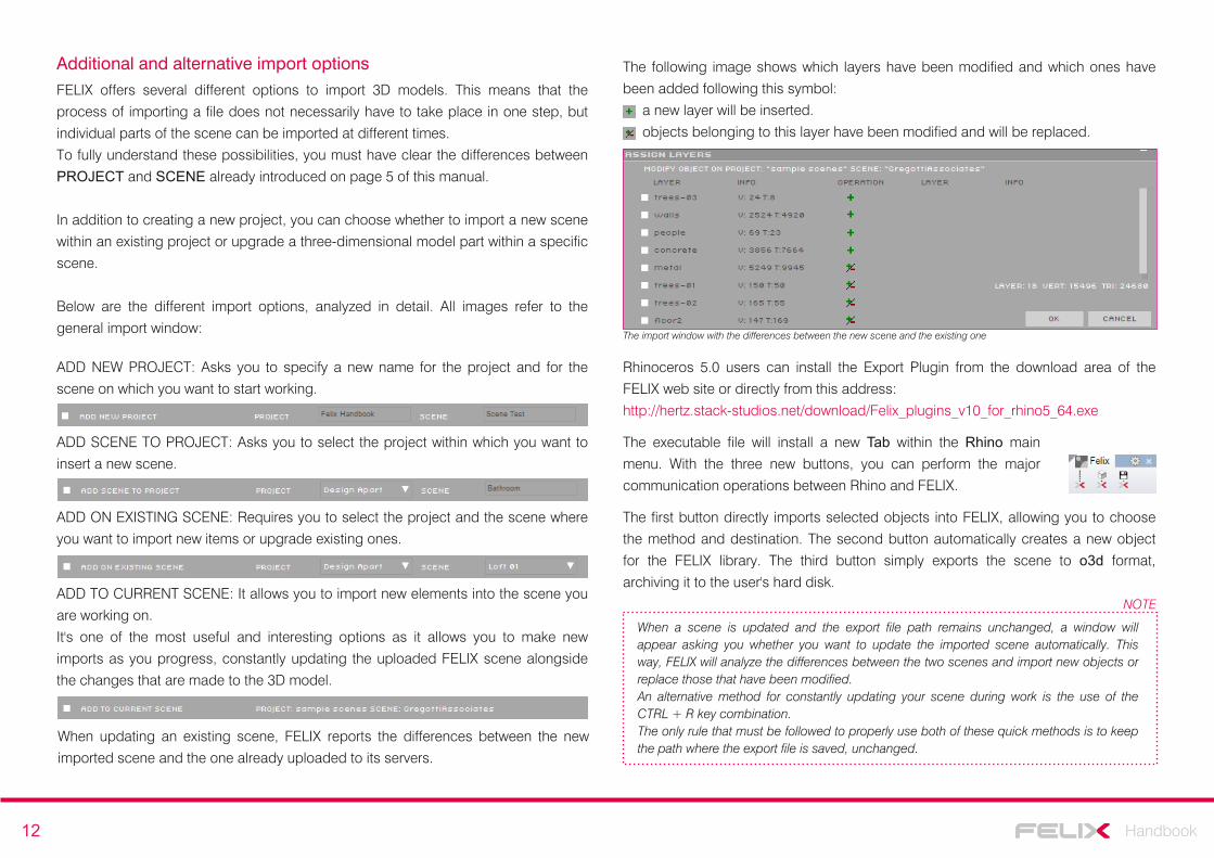
The following image shows which layers have been modified and which ones have
been added following this symbol:
a new layer will be inserted.
objects belonging to this layer have been modified and will be replaced.
The import window with the differences between the new scene and the existing one
When updating an existing scene, FELIX reports the differences between the new
imported scene and the one already uploaded to its servers.
Rhinoceros 5.0 users can install the Export Plugin from the download area of the
FELIX web site or directly from this address:
http://hertz.stack-studios.net/download/Felix_plugins_v10_for_rhino5_64.exe
The executable file will install a new Tab within the Rhino main
menu. With the three new buttons, you can perform the major
communication operations between Rhino and FELIX.
The first button directly imports selected objects into FELIX, allowing you to choose
the method and destination. The second button automatically creates a new object
for the FELIX library. The third button simply exports the scene to o3d format,
archiving it to the user's hard disk.

13 Handbook
Work environments
FELIX’s interface consists of four main windows.
The content of the windows changes according to the type of operation they are
dealing with and corresponds to the various work environments that make up the
software:
Projects, Material Setup, Material Editor, Object Editor and Animation. To access the
different work environments, select their name from the top menu bar. In this part of
the manual, we will look in detail at what you can do only within the four windows of
the Project work environment, the other environments will be described in detail in
their dedicated chapters.
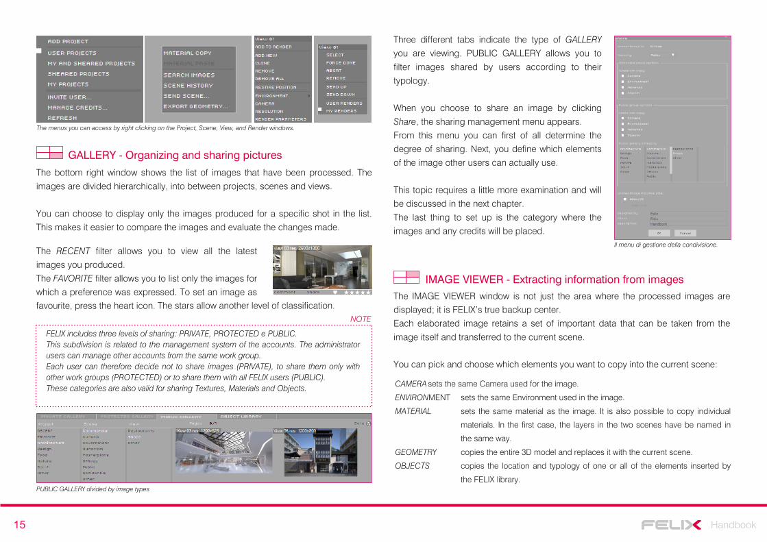
The menu bar is composed of nine different items:
3D VIEW - Placing and controlling the CameraUnlike other software, in FELIX you don’t need to place a Camera in the scene to
frame the models, as the viewpoint of the 3D VIEW window already behaves like and
has all the features of actual cameras.
FELIX allows you to navigate through the scene using different command combinations. Each user can set the navigation according to their preferences and habits. To change the navigation method, go to Options / Open GL / Navigation Mode. From this menu you can choose whether to use the Felix standard method or prefer commands closer to AutoCAD or Rhino.
NOTE
It's also important to remember that the imported scene in FELIX is interactive, so the
mouse pointer "understands" where the scene is, as if it were actually in touch with
the surfaces. With these considerations it is useful to learn some combinations
between mouse and keyboard:
(This tab describes the navigation commands in FELIX MODE).
Rotate Camera r + left mouse button
rotates the camera while standing still. It's like turning your head.
Focal Distance d + left mouse button + click
sets the focus point based on the mouse position.
Orbit Camera o + left mouse button
rotates the camera using the mouse pointer at the center.
Jump j + left mouse button + click
immediately moves the camera to the area where the mouse is located.
Dolly y + left mouse button
moves the camera along the axis of the lens.
Set Horizontal h
places the camera on a horizontal plane.
Zoom Window z + left mouse button + drag
enables Zoom with Selection Window.
Last Saved q
brings the camera to the position of the last saved view.
Import initiates the process of importing 3D models
Save saves projects. If you make changes to more than one project using the
Save button, FELIX saves them all.
Projects used to access to the work environment related to the project
management.
Material Setup is to access to the work environment related to the material assignment to
the scene.
Material Editor is used to access the work environment for creating and modifying
materials.
Object Editor is used to access the work environment for creating and modifying
objects.
Animation permette di accedere all'ambiente di lavoro relativo alla creazione
e gestione delle animazioni.
Options from this menu you can change the password to access FELIX, see how
many credits you have and get scene information, access the account
administration web page, purchase credits, and so on.
Render commences computation of images in the Render Queue.
14 Handbook
Some important camera options are cannot be managed with keystrokes.
They must be changed by dragging the icon next to their value to the right or to the
left.
This allows you to change the Focal Length (zoom: 0.2 = 200mm, 0.02 = 20mm),
FStop (aperture), Aperture Time (800 = 1/800 second, 4 = 1/4 of Second) and
VOffsett (lens decentralization).
PROJECT: Managing Projects and Scenes
This window shows the management tree for your work, divided into Projects,
Scenes, Views and Rendering Tails.
The folder structure FELIX uses to archive projects is simple and intuitive. The
process of creating a new project or a new scene, as it is strictly related to importing
files, has already been covered in this manual.
It may however be useful to look at some of the additional options you can access
by right clicking on the Project column:
ADD PROJECT allows you to directly create a new project without importing any
files.
USER PROJECT allows you to choose which type of filter to apply when viewing
projects. This way, you can only see projects created by the
user, the workgroup, or only those that are publicly shared.
INVITE USER allows you to share the project with a specific FELIX user.
The Scene column lists all the three-dimensional models that have been imported
within the same project.
Even in this case, the most interesting options are nested inside the menu that opens
when clicking on the right mouse button:
MATERIAL COPY allows you to copy all materials from one scene to another (paste material).
To be able to work properly, the two scenes must use the same FELIX layer
nomenclature.
SEARCH IMAGES searches any new rendered images on the server.
The View column shows all the shots that were saved in the same scene. In this
case, the additional operations accessible with the right mouse button are quite
important and articulated.
Pag.47The following page explains all the other operations related to lighting and postproduction settings accessible from the same menu.
The main functions that relate to the management of the views are:
ADD TO RENDER inserts the selected view into the rendering queue.
ADD NEW adds a new frame to those already set by placing the camera in
the default location.
CLONE duplicates the selected view. Useful to find a new shot from one
you already defined.
REMOVE simply deletes the selected view.
The last column in the window is the Render Queue. This window shows all the
renderings in progress, distinguishing them with specific colors
This image represents the four different stages of the rendering process. For View
01, the calculation has not started yet, View 02 is loading on servers, View 03 is
under construction, View 04 is being downloaded to your PC.
The main features that affect render management are accessible as always with the
right mouse button, they are:
FORCE DONE forcibly interrupts the calculation at its current state and the image will be
downloaded to the computer. All credits will be used.
ABORT forcibly interrupts the calculation at its current state but the image will not be
downloaded to the computer. Only credits used for the computation so far
will be used.
REMOVE removes the view from the rendering queue.
SCENE HISTORY allows to download a previous version of the scene from the server.
SEND SCENE sends the scene to another FELIX user.
EXPORT GEOM. downloads the scene in 3ds, lwo, o3d, obj or ply format.
15 Handbook
The menus you can access by right clicking on the Project, Scene, View, and Render windows.
GALLERY - Organizing and sharing pictures
The bottom right window shows the list of images that have been processed. The
images are divided hierarchically, into between projects, scenes and views.
You can choose to display only the images produced for a specific shot in the list.
This makes it easier to compare the images and evaluate the changes made.
FELIX includes three levels of sharing: PRIVATE, PROTECTED e PUBLIC.This subdivision is related to the management system of the accounts. The administrator users can manage other accounts from the same work group. Each user can therefore decide not to share images (PRIVATE), to share them only with other work groups (PROTECTED) or to share them with all FELIX users (PUBLIC).These categories are also valid for sharing Textures, Materials and Objects.
NOTE
The RECENT filter allows you to view all the latest
images you produced.
The FAVORITE filter allows you to list only the images for
which a preference was expressed. To set an image as
favourite, press the heart icon.
PUBLIC GALLERY divided by image types
Three different tabs indicate the type of GALLERY
you are viewing. PUBLIC GALLERY allows you to
filter images shared by users according to their
typology.
When you choose to share an image by clicking
Share, the sharing management menu appears.
From this menu you can first of all determine the
degree of sharing. Next, you define which elements
of the image other users can actually use.
This topic requires a little more examination and will
be discussed in the next chapter.
The last thing to set up is the category where the
images and any credits will be placed.Il menu di gestione della condivisione.
IMAGE VIEWER - Extracting information from imagesThe IMAGE VIEWER window is not just the area where the processed images are
displayed; it is FELIX’s true backup center.
Each elaborated image retains a set of important data that can be taken from the
image itself and transferred to the current scene.
You can pick and choose which elements you want to copy into the current scene:
CAMERA sets the same Camera used for the image.
ENVIRONMENT sets the same Environment used in the image.
MATERIAL sets the same material as the image. It is also possible to copy individual
materials. In the first case, the layers in the two scenes have be named in
the same way.
GEOMETRY copies the entire 3D model and replaces it with the current scene.
OBJECTS copies the location and typology of one or all of the elements inserted by
the FELIX library.
The stars allow another level of classification.
16 Handbook
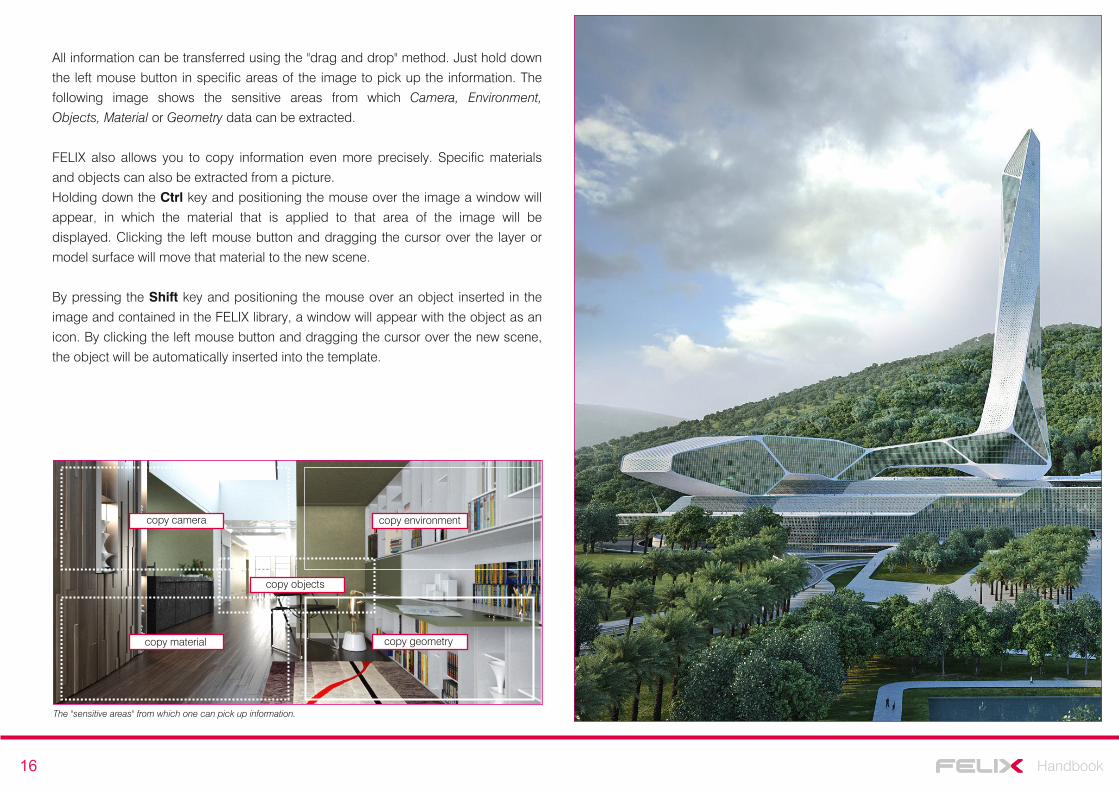
All information can be transferred using the "drag and drop" method. Just hold down
the left mouse button in specific areas of the image to pick up the information. The
following image shows the sensitive areas from which Camera, Environment,
Objects, Material or Geometry data can be extracted.
FELIX also allows you to copy information even more precisely. Specific materials
and objects can also be extracted from a picture.
Holding down the Ctrl key and positioning the mouse over the image a window will
appear, in which the material that is applied to that area of the image will be
displayed. Clicking the left mouse button and dragging the cursor over the layer or
model surface will move that material to the new scene.
By pressing the Shift key and positioning the mouse over an object inserted in the
image and contained in the FELIX library, a window will appear with the object as an
icon. By clicking the left mouse button and dragging the cursor over the new scene,
the object will be automatically inserted into the template.
copy camera copy environment
copy objects
copy material copy geometry
The "sensitive areas" from which one can pick up information.
17 Handbook
Assigning materials
You can assign materials in FELIX by "dragging and dropping". This makes the
procedure extremely simple and intuitive.
The library offers about 10,000 professional-grade materials with resolutions ranging
from 4 to 16 Megapixels. It won’t be difficult to find the material that best suits your
needs. The library is also subdivided into thematic categories and allows you to
perform searches based on a series of filters.
Pag.7Though materials assignment has been briefly addressed in the page above,in this chapter, the topic will be discussed in more detail.
To access the materials management windows, you must first of all enable the view
by clicking Material Setup on the menu bar. This will change both the lower FELIX
windows as well as allow you to choose the materials and assign them to your
project’s layers.
Associating materials to layers
Assignment of materials takes place by association.
After selecting the material from the library, associate it to the layer containing the
objects represented by the same material.
It is important to work with an orderly scene and with layers named properly. If the
scene is well-organized, it will be much easier to assign materials, selectively switch
off items, assign map coordinates, and so on.
All the materials available in the FELIX library are grouped in different categories in
the bottom right window.
Just select the desired category and drag the preview of the material to its layer.
Alternatively, you can drag the preview directly into the 3D VIEW window on the item
to which the selected material will be applied.
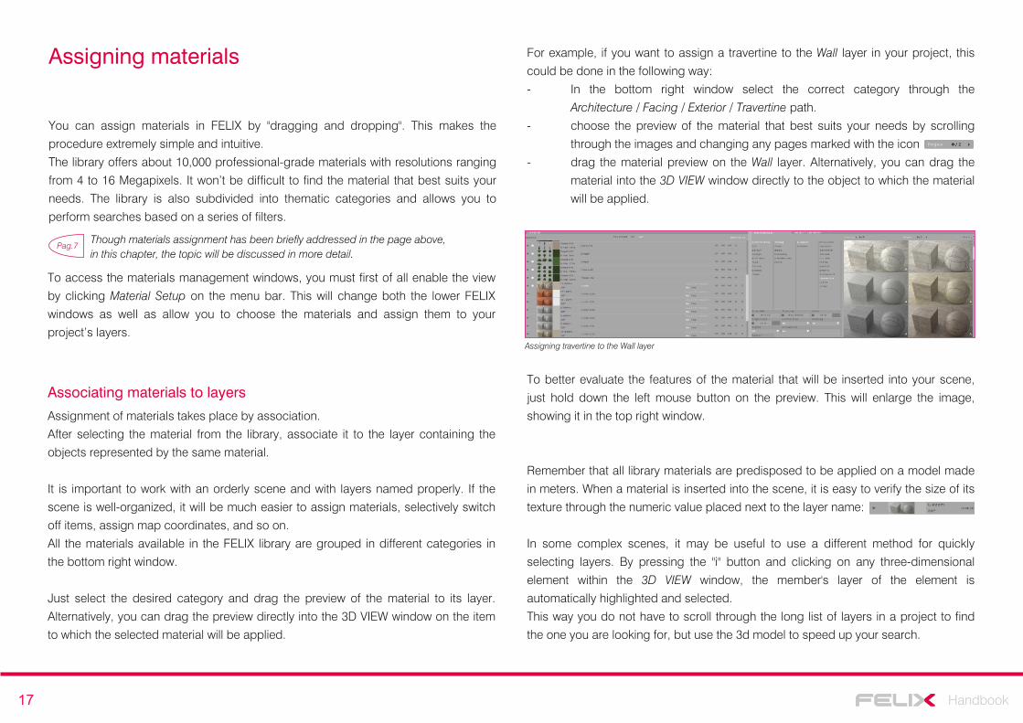
For example, if you want to assign a travertine to the Wall layer in your project, this
could be done in the following way:
- In the bottom right window select the correct category through the
Architecture / Facing / Exterior / Travertine path.
- choose the preview of the material that best suits your needs by scrolling
through the images and changing any pages marked with the icon
- drag the material preview on the Wall layer. Alternatively, you can drag the
material into the 3D VIEW window directly to the object to which the material
will be applied.
Assigning travertine to the Wall layer
To better evaluate the features of the material that will be inserted into your scene,
just hold down the left mouse button on the preview. This will enlarge the image,
showing it in the top right window.
Remember that all library materials are predisposed to be applied on a model made
in meters. When a material is inserted into the scene, it is easy to verify the size of its
texture through the numeric value placed next to the layer name:
In some complex scenes, it may be useful to use a different method for quickly
selecting layers. By pressing the "i" button and clicking on any three-dimensional
element within the 3D VIEW window, the member's layer of the element is
automatically highlighted and selected.
This way you do not have to scroll through the long list of layers in a project to find
the one you are looking for, but use the 3d model to speed up your search.
18 Handbook
Managing layers
FELIX layers do not only provide a list of the elements in the project, they enable
many operations related to the management of the scene and materials.
It is important to emphasize that when an object is turned off, this is not considered during the computation of the image. It can therefore be useful to turn off the complex elements that are not framed in the scene on which you are working. This can improve the quality of the final image and reduce the rendering time.
NOTE
By clicking on the white square to the left of each layer all elements belonging to the
layer are turned on or off.
FELIX also allows you to extrude surfaces that have been imported without
thickness. The classic case can be glass modeled with simple surfaces. The Layer
Extrusion parameter allows you to apply a layer thickness to the elements on the
layer. When the option is active, a relative numeric value indicates the extrusion
dimension. The value can be changed with just one click.
On the right side of each layer there are four useful commands that intervene only
during the calculation phase:
HC hides objects only from the camera. The objects continue to be present within the
scene, but the camera does not display them.
HR makes the reflections and refractions generated by the objects within the layer
invisible.
HG objects are not considered when calculating global illumination. In this case, objects
generate reflections and refractions but do not generate shadows.
M/S these two options allow you to not render objects but only consider the shadows that
they receive and then reuse them during photo retouching.
Pag.47This page explains all the steps to take in order to control these advanced layer management options.
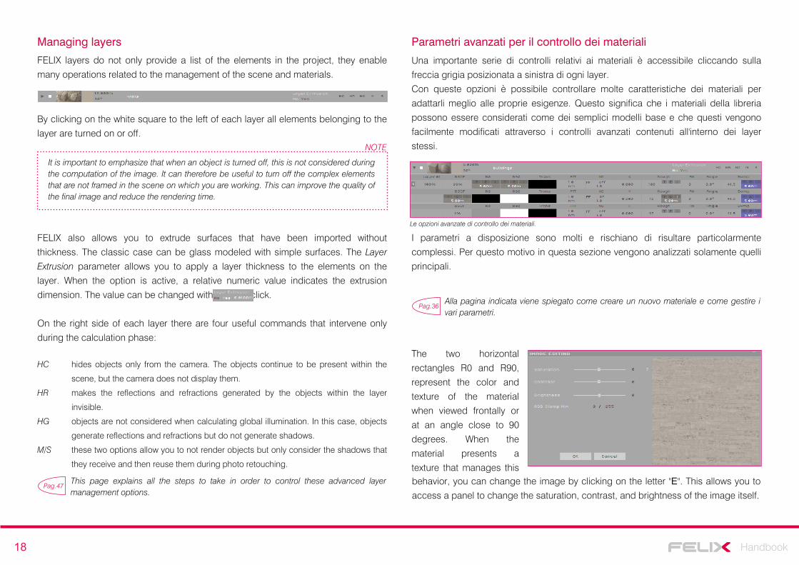
Parametri avanzati per il controllo dei materiali
Una importante serie di controlli relativi ai materiali è accessibile cliccando sulla
freccia grigia posizionata a sinistra di ogni layer.
Con queste opzioni è possibile controllare molte caratteristiche dei materiali per
adattarli meglio alle proprie esigenze. Questo significa che i materiali della libreria
possono essere considerati come dei semplici modelli base e che questi vengono
facilmente modificati attraverso i controlli avanzati contenuti all'interno dei layer
stessi.
Le opzioni avanzate di controllo dei materiali.
Pag.36Alla pagina indicata viene spiegato come creare un nuovo materiale e come gestire i vari parametri.
I parametri a disposizione sono molti e rischiano di risultare particolarmente
complessi. Per questo motivo in questa sezione vengono analizzati solamente quelli
principali.
The two horizontal
rectangles R0 and R90,
represent the color and
texture of the material
when viewed frontally or
at an angle close to 90
degrees. When the
material presents a
texture that manages thisbehavior, you can change the image by clicking on the letter "E". This allows you to
access a panel to change the saturation, contrast, and brightness of the image itself.
19 Handbook
The reflection of the material is controlled by the parameter "K". Increasing the value
will also increase reflection.
The Rough parameter, on the other hand, intervenes on the roughness of the
material, thus influencing the blur of reflection.
A value close to 0 generates a very precise reflection, simulating a glossy finish; a
value close to 100 generates a widespread reflection, characteristic of a rougher
surface.
The Bump parameter controls roughness simulation by using a simple texture or
Normal Map. The force of the effect is handled by the numeric value next to the
texture. High numbers make for the most obvious effect.
By changing the metric values in the texture’s text boxes, you can increase or
decrease the size of the image used to simulate the material.
Instead, the value expressed in degrees acts on the beveling of the objects. This
value is set by default at 30 °. This means that if two surfaces form an angle below
30°, FELIX will try to blend the point of union between the two surfaces, returning a
continuity between the surfaces of an object that is actually multifaceted in the three-
dimensional model.
Setting map coordinates
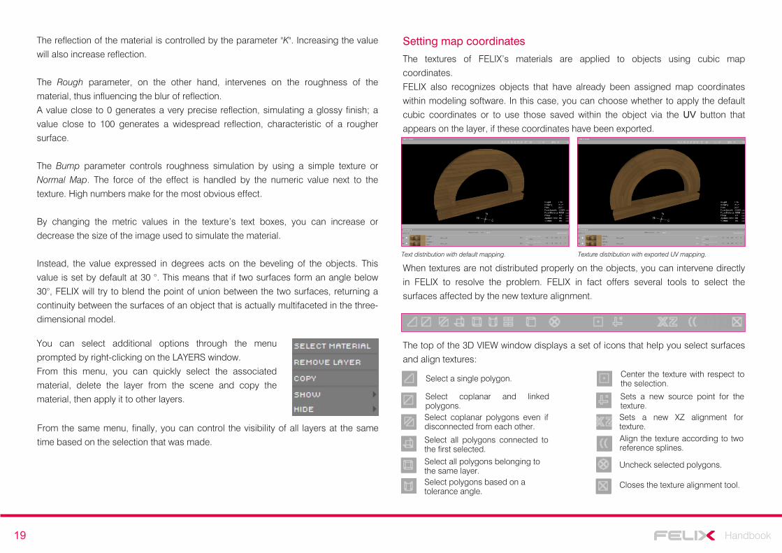
The textures of FELIX’s materials are applied to objects using cubic map
coordinates.
FELIX also recognizes objects that have already been assigned map coordinates
within modeling software. In this case, you can choose whether to apply the default
cubic coordinates or to use those saved within the object via the UV button that
appears on the layer, if these coordinates have been exported.
You can select additional options through the menu
prompted by right-clicking on the LAYERS window.
From this menu, you can quickly select the associated
material, delete the layer from the scene and copy the
material, then apply it to other layers.
When textures are not distributed properly on the objects, you can intervene directly
in FELIX to resolve the problem. FELIX in fact offers several tools to select the
surfaces affected by the new texture alignment.
Text distribution with default mapping. Texture distribution with exported UV mapping.
The top of the 3D VIEW window displays a set of icons that help you select surfaces
and align textures:
Select a single polygon.
Select coplanar and linked polygons.Select coplanar polygons even if disconnected from each other.
Select all polygons connected to the first selected.Select all polygons belonging to the same layer.
Sets a new source point for the texture.Sets a new XZ alignment for texture.
Uncheck selected polygons.
Closes the texture alignment tool.
Center the texture with respect to the selection.
Select polygons based on a tolerance angle.
Align the texture according to two reference splines.
From the same menu, finally, you can control the visibility of all layers at the same
time based on the selection that was made.
20 Handbook
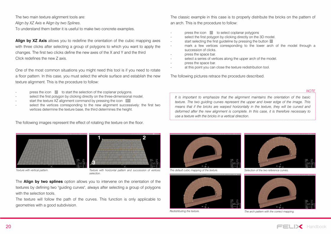
- press the icon to start the selection of the coplanar polygons.- select the first polygon by clicking directly on the three-dimensional model.- start the texture XZ alignment command by pressing the icon- select the vertices corresponding to the new alignment successively: the first two
vertices determine the texture base, the third determines the height.
The following images represent the effect of rotating the texture on the floor.
Texture with vertical pattern. Texture with horizontal pattern and succession of vertices selection.
The two main texture alignment tools are:
Align by XZ Axis e Align by two Splines.
To understand them better it is useful to make two concrete examples.
Align by XZ Axis allows you to redefine the orientation of the cubic mapping axes
with three clicks after selecting a group of polygons to which you want to apply the
changes. The first two clicks define the new axes of the X and Y and the third
Click redefines the new Z axis.
One of the most common situations you might need this tool is if you need to rotate
a floor pattern. In this case, you must select the whole surface and establish the new
texture alignment. This is the procedure to follow:
The Align by two splines option allows you to intervene on the orientation of the
textures by defining two "guiding curves", always after selecting a group of polygons
with the selection tools.
The texture will follow the path of the curves. This function is only applicable to
geometries with a good subdivision.
The classic example in this case is to properly distribute the bricks on the pattern of
an arch. This is the procedure to follow:
The default cubic mapping of the texture. Selection of the two reference curves.
Redistributing the texture. The arch pattern with the correct mapping.
- press the icon to select coplanar polygons- select the first polygon by clicking directly on the 3D model.- start selecting the first guideline by pressing the button- mark a few vertices corresponding to the lower arch of the model through a
succession of clicks.- press the space bar.- select a series of vertices along the upper arch of the model.- press the space bar.- at this point you can close the texture redistribution tool.
The following pictures retrace the procedure described.
It is important to emphasize that the alignment maintains the orientation of the basic texture. The two guiding curves represent the upper and lower edge of the image. This means that if the bricks are warped horizontally in the texture, they will be curved and deformed after the new alignment is complete. In this case, it is therefore necessary to use a texture with the bricks in a vertical direction.
NOTE
21 Handbook
Inserting objects
The object library provides you with more than 3,000 ready-to-use 3D models,
divided into categories. As with materials, objects can also be inserted and shared
by users. This means that the library is continuously developing and new objects are
constantly being inserted. It should also worth remembering that you can always
change the materials assigned to the objects in the library. This makes the
possibilities for personalization of models truly infinite.
You can insert objects into your scenes in two different ways, depending on the task
at hand.
The simplest method is the classic "drag and drop" taking items from the library and
inserting them into the scene.
The second is the "substitute triangles" method. This technique allows you import a
series of small triangular surfaces that will act as markers and replace them with real
three-dimensional objects.
In this way you can instantly insert thousands of objects, even assigning random
variations in scale and rotation to them, in order to increase the degree of realism.
Pag.8This page explains how the colored cube with arrows works as a method to represent objects. In this chapter, however, we will look at the changes you can edit the objects and how to manage multitudes of objects with the substitute triangle system.
The object library
To access the object library, enter the Material Setup workspace from the main
menu. In the lower right window, select the OBJECT LIBRARY tab.
The objects are subdivided into 15 main categories, each of which contains further
subcategories of similar objects.
Almost any 3D model can be inserted as an object into the FELIX library. In the
Architecture category, for example, you can find entire buildings and quickly create
an urban environment.
Pag.42This page explains all the steps necessary to import a new item, assign the materials and place it in the library.
Objects. Moving, rotating, and editing materials
After selecting the desired object, place it in the scene by a simple drag and drop.
Remember that all objects are programmed to stick to surfaces. An object can be
set to adhere to the floor, wall or ceiling. From the preview of the object itself it is
easy to understand what the established placement is. As with materials, even
previewing objects can be easily enlarged by simply holding down the left mouse
button on their image.
When the object is in the scene, it is displayed as a colored box with arrows. With
some combinations of controls you can move or rotate the object with extreme
precision.
To control objects, you must first click on the icon in the top bar of the 3D
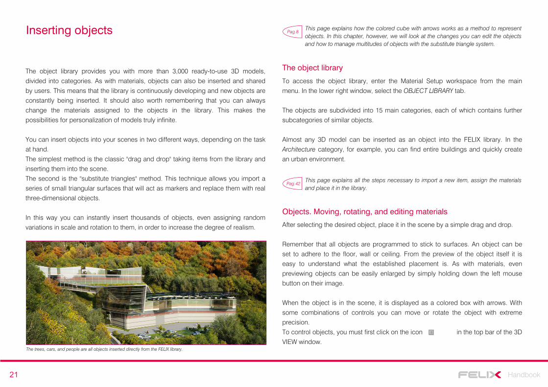
VIEW window.The trees, cars, and people are all objects inserted directly from the FELIX library.
22 Handbook
You can move the object freely along the surface of the plane simply by selecting it
and holding down the left mouse button.
With other key combinations, additional object operations are possible:
Clone "shift" + left mouse button
clones the selected object.
Mult.Select "ctrl" + left mouse button + click
selects a series of objects with subsequent clicks.
Light Target T + left mouse button
defines the direction in which to orient an object. This command is
particularly useful for effectively directing lights.
The last operation, which can be performed quickly on any object, is modifying
material properties.
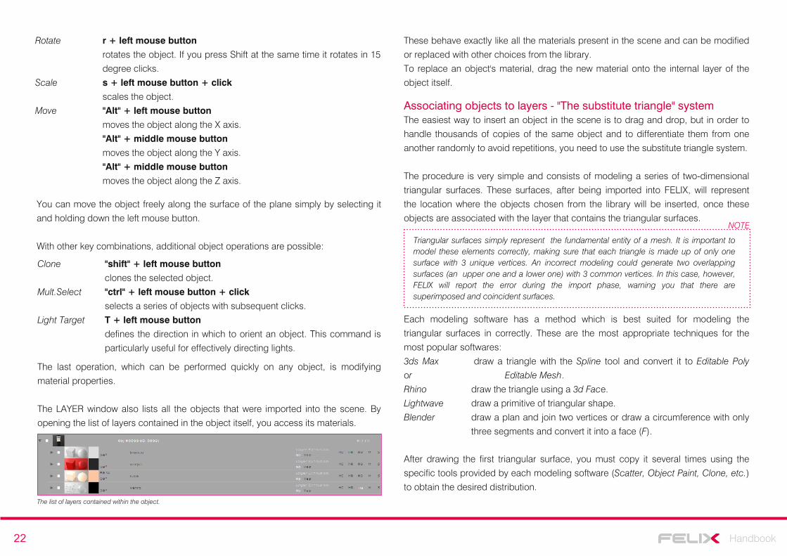
The LAYER window also lists all the objects that were imported into the scene. By
opening the list of layers contained in the object itself, you access its materials.
The list of layers contained within the object.
Associating objects to layers - "The substitute triangle" systemThe easiest way to insert an object in the scene is to drag and drop, but in order to
handle thousands of copies of the same object and to differentiate them from one
another randomly to avoid repetitions, you need to use the substitute triangle system.
The procedure is very simple and consists of modeling a series of two-dimensional
triangular surfaces. These surfaces, after being imported into FELIX, will represent
the location where the objects chosen from the library will be inserted, once these
objects are associated with the layer that contains the triangular surfaces.
Triangular surfaces simply represent the fundamental entity of a mesh. It is important to model these elements correctly, making sure that each triangle is made up of only one surface with 3 unique vertices. An incorrect modeling could generate two overlapping surfaces (an upper one and a lower one) with 3 common vertices. In this case, however, FELIX will report the error during the import phase, warning you that there are superimposed and coincident surfaces.
NOTE
Each modeling software has a method which is best suited for modeling the
triangular surfaces in correctly. These are the most appropriate techniques for the
most popular softwares:
3ds Max draw a triangle with the Spline tool and convert it to Editable Poly
or Editable Mesh.
Rhino draw the triangle using a 3d Face.
Lightwave draw a primitive of triangular shape.
Blender draw a plan and join two vertices or draw a circumference with only
three segments and convert it into a face (F).
After drawing the first triangular surface, you must copy it several times using the
specific tools provided by each modeling software (Scatter, Object Paint, Clone, etc.)
to obtain the desired distribution.
Rotate r + left mouse button
rotates the object. If you press Shift at the same time it rotates in 15
degree clicks.
Scale s + left mouse button + click
scales the object.
Move "Alt" + left mouse button
moves the object along the X axis.
"Alt" + middle mouse button
moves the object along the Y axis.
"Alt" + middle mouse button
moves the object along the Z axis.
These behave exactly like all the materials present in the scene and can be modified
or replaced with other choices from the library.
To replace an object's material, drag the new material onto the internal layer of the
object itself.
23 Handbook
It is important to check the direction of the normal vectors on the surfaces you made.
FELIX objects will follow the direction of the normal’s positive. For example, if you are
placing the triangles to place a series of trees, the normal vectors should point
upwards.
It is important to point out that you can insert different objects into the same layer. If
you want to distribute trees, the triangles can all be in one layer, but in FELIX you can
assign to the layer pines, shrubs and birches. In this way, the three objects will be
randomly distributed amongst the triangles, helping to produce a more realistic
effect.
FELIX provides a number of very useful operations to control these large quantities
of repeated objects.
By opening the content of the layer to which the objects have been associated, you
access a variety of options to control scale, rotation, and the variation frequency.
The Density parameter allows you to determine the frequency with which a specific
object will be inserted into the scene. An object always has priority over those that
follow it. This means that if there are 3 objects assigned to the same layer and the
first one has a 50% frequency, the others will automatically be set to 25% each.
The second parameter that can be changed is the maximum and minimum rotation
allowed for each object (Min.Rot var. And Max.Rot var.). with the Step parameter, you
can also decide by how many degrees the object will rotate based on the other
instances.
Variation in scale can also be controlled. With the parameters contained in the same
panel, you can set a maximum and minimum scale, with the added option of tying
the variation to the horizontal or the vertical axis only.
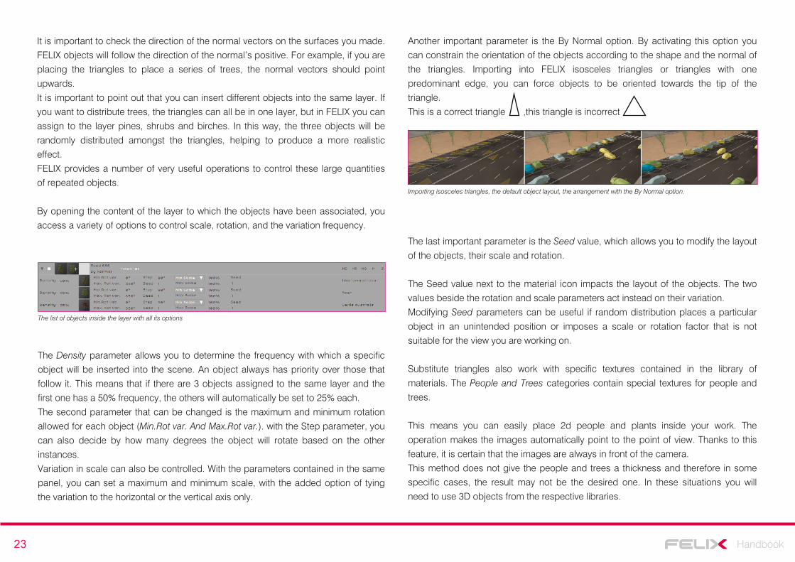
Another important parameter is the By Normal option. By activating this option you
can constrain the orientation of the objects according to the shape and the normal of
the triangles. Importing into FELIX isosceles triangles or triangles with one
predominant edge, you can force objects to be oriented towards the tip of the
triangle.
This is a correct triangle ,this triangle is incorrect
The last important parameter is the Seed value, which allows you to modify the layout
of the objects, their scale and rotation.
The Seed value next to the material icon impacts the layout of the objects. The two
values beside the rotation and scale parameters act instead on their variation.
Modifying Seed parameters can be useful if random distribution places a particular
object in an unintended position or imposes a scale or rotation factor that is not
suitable for the view you are working on.
Substitute triangles also work with specific textures contained in the library of
materials. The People and Trees categories contain special textures for people and
trees.
This means you can easily place 2d people and plants inside your work. The
operation makes the images automatically point to the point of view. Thanks to this
feature, it is certain that the images are always in front of the camera.
This method does not give the people and trees a thickness and therefore in some
specific cases, the result may not be the desired one. In these situations you will
need to use 3D objects from the respective libraries.
The list of objects inside the layer with all its options
Importing isosceles triangles, the default object layout, the arrangement with the By Normal option.
24 Handbook
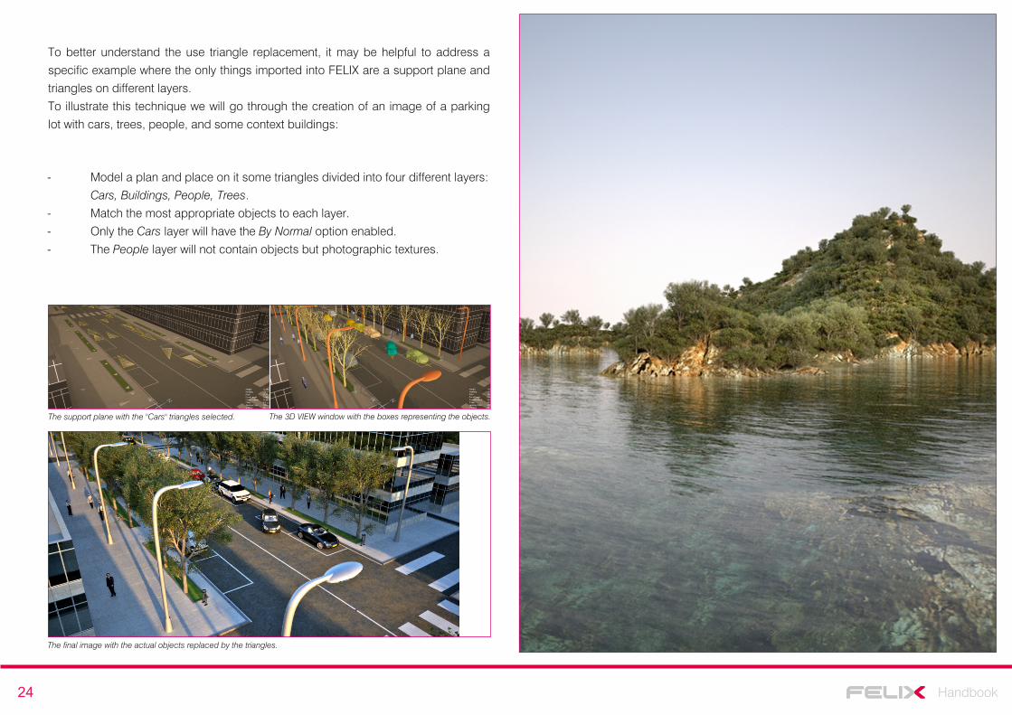
To better understand the use triangle replacement, it may be helpful to address a
specific example where the only things imported into FELIX are a support plane and
triangles on different layers.
To illustrate this technique we will go through the creation of an image of a parking
lot with cars, trees, people, and some context buildings:
- Model a plan and place on it some triangles divided into four different layers:
Cars, Buildings, People, Trees.
- Match the most appropriate objects to each layer.
- Only the Cars layer will have the By Normal option enabled.
- The People layer will not contain objects but photographic textures.
The final image with the actual objects replaced by the triangles.
The support plane with the "Cars" triangles selected. The 3D VIEW window with the boxes representing the objects.
25 Handbook
Natural light - outdoor scene
FELIX offers several methods to illuminate your scenes.
In outdoor environments, you can achieve highly realistic results using one of the
many HDRI images available.
If, however, you want to change the scene's overall lighting parameters accurately,
you may want to use a physical sky or a monochrome light head.
FELIX allows you to choose the most suitable lighting method for the expected
result.
To assign an environment to a view, simply open the ENVIRONMENT LIBRARY
SETUP window by right-clicking on a view and selecting the ENVIRONMENT item.
From here you can choose how to illuminate your scene by selecting one of the
available options.
Environment, Physical Sky, Sky Dome
The most commonly used method to illuminate an external scene involves assigning
an environment based from an HDRI image.
From the ENVIRONMENT LIBRARY menu, you can access a window to choose the
image that will determine the scene lighting. Different categories group the images by
typology. In this window, simply select the desired setting and press the OK button to
assign the lighting.
By holding down the "N" key and the left mouse button in the 3D VIEW window you
can rotate the spherical image that illuminates the scene. In this way you can easily
adjust the direction of the light source.
The faces of the 3D model will be illuminated consistently with respect to the image,
making directing the light easier and more intuitive.
The selection window with HDRI images to use as Environments
Pag.7This page explains the technique for quickly setting the lighting direction by rotating the environment.
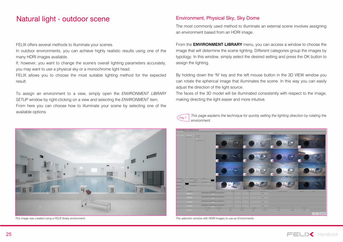
This image was created using a FELIX library environment.
26 Handbook
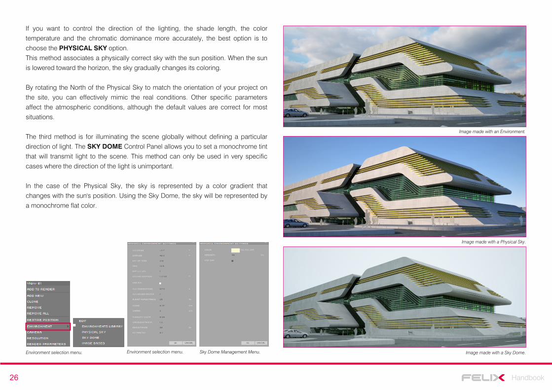
If you want to control the direction of the lighting, the shade length, the color
temperature and the chromatic dominance more accurately, the best option is to
choose the PHYSICAL SKY option.
This method associates a physically correct sky with the sun position. When the sun
is lowered toward the horizon, the sky gradually changes its coloring.
By rotating the North of the Physical Sky to match the orientation of your project on
the site, you can effectively mimic the real conditions. Other specific parameters
affect the atmospheric conditions, although the default values are correct for most
situations.
The third method is for illuminating the scene globally without defining a particular
direction of light. The SKY DOME Control Panel allows you to set a monochrome tint
that will transmit light to the scene. This method can only be used in very specific
cases where the direction of the light is unimportant.
In the case of the Physical Sky, the sky is represented by a color gradient that
changes with the sun's position. Using the Sky Dome, the sky will be represented by
a monochrome flat color.
Environment selection menu. Sky Dome Management Menu.
Image made with an Environment.
Image made with a Physical Sky.
Image made with a Sky Dome.Environment selection menu.
27 Handbook
Tutorial - An external scene
To better understand how to work with an external scene and to use some of the
tools that described above, it may be helpful to follow this tutorial.
We will look at how to make a lawn with three-dimensional blades of grass, how to
properly insert water in your scene, how to illuminate the scene using HDRI images,
and how to position additional objects taken from the library.
First of all, model and import into FELIX an external scene with the following layers:
Walls, Glass, Frame, Water, Grass, Hedge, Terrain and Trees.
The Grass, Hedge, and Trees layers will only contain the triangular polygons required
for the distribution of grass, a hedge and trees for context.
After importing the three-dimensional model, you must assign the materials to the
different layers. Assign materials by the dragging and dropping them directly onto
the scene or on their respective layers.
Flooring and facade finishes can be tailored to your needs but glass and water
require some specific attention to achieve optimum results.
Assign to the Glass layer the material with ID 456, stored in the architecture / glass /
plain path. FELIX will ask if you want to apply an extrusion to the layer. If the glass
has been modeled with a single surface it is best to confirm the extrusion, set to 1
cm by default.
If, on the other hand, the glass already has a thickness, there is no need to apply it
again.
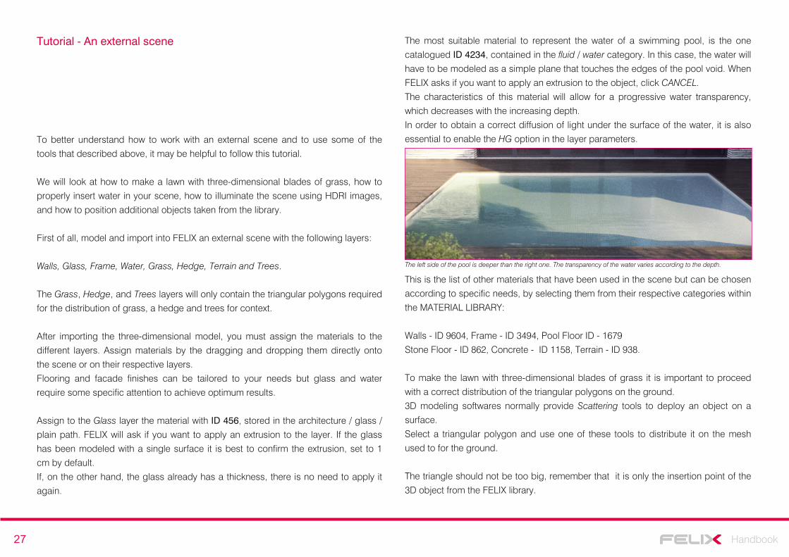
The most suitable material to represent the water of a swimming pool, is the one
catalogued ID 4234, contained in the fluid / water category. In this case, the water will
have to be modeled as a simple plane that touches the edges of the pool void. When
FELIX asks if you want to apply an extrusion to the object, click CANCEL.
The characteristics of this material will allow for a progressive water transparency,
which decreases with the increasing depth.
In order to obtain a correct diffusion of light under the surface of the water, it is also
essential to enable the HG option in the layer parameters.
This is the list of other materials that have been used in the scene but can be chosen
according to specific needs, by selecting them from their respective categories within
the MATERIAL LIBRARY:
Walls - ID 9604, Frame - ID 3494, Pool Floor ID - 1679
Stone Floor - ID 862, Concrete - ID 1158, Terrain - ID 938.
To make the lawn with three-dimensional blades of grass it is important to proceed
with a correct distribution of the triangular polygons on the ground.
3D modeling softwares normally provide Scattering tools to deploy an object on a
surface.
Select a triangular polygon and use one of these tools to distribute it on the mesh
used to for the ground.
The triangle should not be too big, remember that it is only the insertion point of the
3D object from the FELIX library.
The left side of the pool is deeper than the right one. The transparency of the water varies according to the depth.
28 Handbook
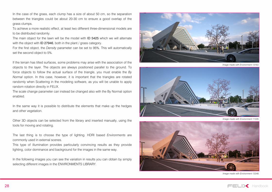
Image made with Environment 13163.
Image made with Environment 11335.
Image made with Environment 13348.
In the case of the grass, each clump has a size of about 50 cm, so the separation
between the triangles could be about 20-30 cm to ensure a good overlap of the
grass clumps.
To achieve a more realistic effect, at least two different three-dimensional models are
to be distributed randomly.
The main object for the lawn will be the model with ID 5425 which we will alternate
with the object with ID 27946, both in the plant / grass category.
For the first object, the Density parameter can be set to 95%. This will automatically
set the second object to 5%.
If the terrain has tilted surfaces, some problems may arise with the association of the
objects to the layer. The objects are always positioned parallel to the ground. To
force objects to follow the actual surface of the triangle, you must enable the By
Normal option. In this case, however, it is important that the triangles are rotated
randomly when Scattering in the modeling software, as you will be unable to apply
random rotation directly in FELIX.
The scale change parameter can instead be changed also with the By Normal option
enabled.
In the same way it is possible to distribute the elements that make up the hedges
and other vegetation.
Other 3D objects can be selected from the library and inserted manually, using the
tools for moving and rotating.
The last thing is to choose the type of lighting. HDRI based Environments are
commonly used in external scenes.
This type of illumination provides particularly convincing results as they provide
lighting, color dominance and background for the images in the same way.
In the following images you can see the variation in results you can obtain by simply
selecting different images in the ENVIRONMENTS LIBRARY.
29 Handbook
Artificial light - interior scenes
Setting the lighting correctly for an indoor scene is slightly more complex than for an
outdoor scene.
In interior scenes, most of the light is reflected on the surfaces, generating a diffuse
illumination. In such cases, the contribution from direct light is only marginal.
For this reason, it is important to know the best techniques to allow light to spread,
reducing the amount of noise produced during computation.
Noise is in fact the main consequence of incorrect illumination.
There are a number of small tricks and adjustments you can make to increase the
amount of light coming from outside and you can further enhance the lighting level
by inserting diffused lights into your interior.
Remember that the camera's default parameters are set for a very bright outdoor
scene. Instead, exposure for an interior scene should between 1/200 and 1/20 of a
second.
When you start adjusting the lighting of an interior space, you should avoid applying
materials to the scene and inserting objects from the library. This simplifies the
calculation by reducing noise and processing time, allowing you to focus solely on
light.
The material that is assigned by default to all imported objects has the correct
features to better spread the light and to start setting the lighting properly.
Before looking at lighting techniques for indoor environments in detail, it is necessary
to describe the two main sources of artificial illumination present in FELIX: library
lights and emitter material.
Lights from the library
The FELIX object library provides a good amount of ready-to-use 3D dimensional
models to illuminate the scene naturally.
The light fixtures inserted in the objects of the library are calibrated to emit the same
brightness as the objects they mimic.
In order to emit light, specific materials are used to set the value in Watt, Lumen or
Candles. It is therefore easy to adjust the intensity of artificial lights simply based on
the values common to any bulb.
It is good practice to use light values which are similar to real life. The brightness of the scene should be controlled by the camera's exposure time rather by the brightness level of the light sources. Setting the values in Watt, Lumen or Candles correctly will also result in more realistic results and making more difficult to incur an incorrect balancing of the lights.
NOTE
As usual, objects in the library are cataloged according to their typology. The Lighting
section contains all the objects needed to illuminate scenes with artificial light.
These three-dimensional models have all the features of FELIX objects. This means
that they can be imported to the scene simply by using the drag and drop technique
and can be positioned using the triangle replacement system.
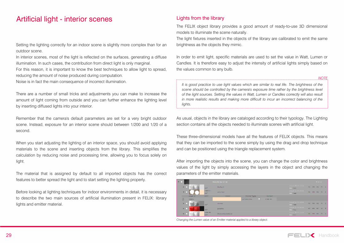
After importing the objects into the scene, you can change the color and brightness
values of the light by simply accessing the layers in the object and changing the
parameters of the emitter materials.
Changing the Lumen value of an Emitter material applied to a library object.
30 Handbook
The emitter material
There are no ‘true’ lights in FELIX. Light sources transmit light through a particular material called Emitter.
Emitter values can be set intuitively as they refer to real units of measure such as
Lumen, Lux, Watt or Candles.
For example, an incandescent bulb has a value between 60 and 100 watts, while a
neon produces about 6000 lumens per linear meter.
By simply referring to real-world measures, you will be able to achieve accurate and
well-balanced results.
Another way to radically vary the outcome of your images is by controlling the color
of the emitter. This way you can control the temperature of the entire image as well
as only parts of it. The FELIX camera, in fact, does not allow for white balance, as
this is set to 6500K by default.
Emitter materials are contained in a specific category in the library.
Although there are several materials of this type ready for use, the most commonly
used are the first two listed:
ID 3044 - brightness is set in lumens per square meter. By increasing the illuminating surface, you obtain a relative increase in the brightness of the object.ID 195 - brightness is set in lumens. The value is absolute and therefore the brightness does not depend on the surface of the illuminating body.
To use the Emitters correctly and to get the best results, it's good to use some
simple formulas during modeling:
- Normal surfaces should have the same direction of light emission.
- The surfaces should not have any thickness.
- The surfaces should be as simple as possible. To simulate a light bulb, if the
viewpoint allows it, it is best to represent it with a cube rather than with a sphere.
This greatly simplifies the calculation and reduces the noise of the final image.
In order to illuminate an interior scene, four different approaches can be used, and
virtually all of them use Emitters.
The simplest way is to illuminate the scene using an Environment. In this case, the
model must have large windows that allow outside light to enter the room. The
direction of the light can be changed by simply rotating the outside environment.
Windows however do not always provide enough lighting, especially if they are small.
In such cases, this method is likely to produce excessive noise. To solve the
problem,often it is enough to add a few more sources of illumination to the scene.
An effective method to illuminate interiors with small openings for natural light is to
place emitter surfaces outside the windows. This technique drastically reduces
noise and produces very natural results. All you have to do is place immediately
outside of the openings, surfaces the normals of which face the inside of the room.
Alternatively you can apply the emitter material directly to the glass.
To add neon-like artificial illumination, simply model some two dimensional
surfaces and place them a few millimeters underneath the ceiling, with normals
facing the floor. Then apply the most suitable emitter material.
The last type of illumination for interior scenes involves inserting three-dimensional
objects selected from the library into the scene. All these objects already have an
Emitter material applied to the light fixture, which you can easily modify according to
your needs.
If you are modeling your own emitting surfaces, make sure they don’t intersect each other. This would lead to an increase in noise and calculation times. For the same reason, you shouldn’t insert more than 10 different types of emitter into the same scene.If a you are using glass material from the Design section of the library for your windows, it is advisable to enable the HG option inside the layer to improve lighting and reduce noise.
NOTE
31 Handbook
Tutorial - controlling lighting for an interior scene
Interior scene lighting can be complex. It is therefore advisable to know the different
techniques necessary to obtain convincing results in all possible situations.
In this tutorial, the various procedures will be handled in a practical way so that you
can easily choose the one that best suits your needs.
The most intuitive approach is to illuminate the scene using the outside environment.
This technique is very easy, but allows for optimal results only in specific situations.
In order for it to work, large openings are essential, to let in as much light as
possible.
Using an Environment to light indoor spaces is therefore a good solution if you
project features glass roofs or completely transparent walls.
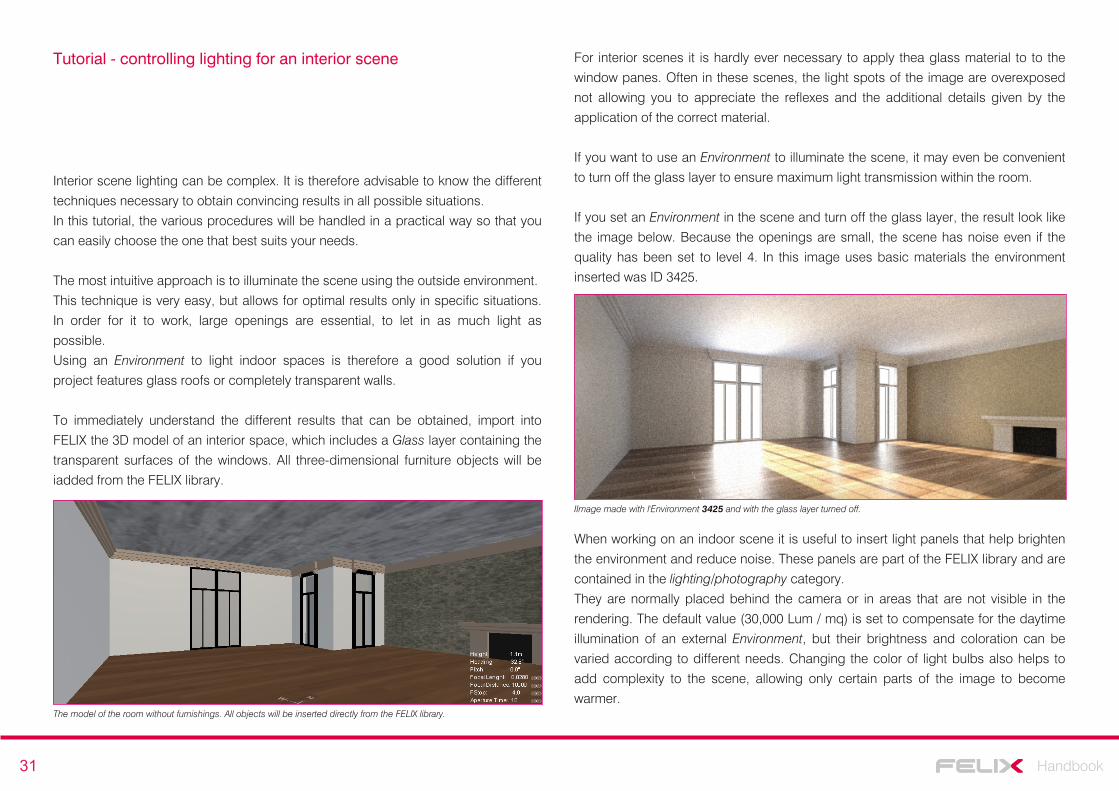
To immediately understand the different results that can be obtained, import into
FELIX the 3D model of an interior space, which includes a Glass layer containing the
transparent surfaces of the windows. All three-dimensional furniture objects will be
iadded from the FELIX library.
For interior scenes it is hardly ever necessary to apply thea glass material to to the
window panes. Often in these scenes, the light spots of the image are overexposed
not allowing you to appreciate the reflexes and the additional details given by the
application of the correct material.
If you want to use an Environment to illuminate the scene, it may even be convenient
to turn off the glass layer to ensure maximum light transmission within the room.
If you set an Environment in the scene and turn off the glass layer, the result look like
the image below. Because the openings are small, the scene has noise even if the
quality has been set to level 4. In this image uses basic materials the environment
inserted was ID 3425.
The model of the room without furnishings. All objects will be inserted directly from the FELIX library.
IImage made with l'Environment 3425 and with the glass layer turned off.
When working on an indoor scene it is useful to insert light panels that help brighten
the environment and reduce noise. These panels are part of the FELIX library and are
contained in the lighting/photography category.
They are normally placed behind the camera or in areas that are not visible in the
rendering. The default value (30,000 Lum / mq) is set to compensate for the daytime
illumination of an external Environment, but their brightness and coloration can be
varied according to different needs. Changing the color of light bulbs also helps to
add complexity to the scene, allowing only certain parts of the image to become
warmer.
32 Handbook
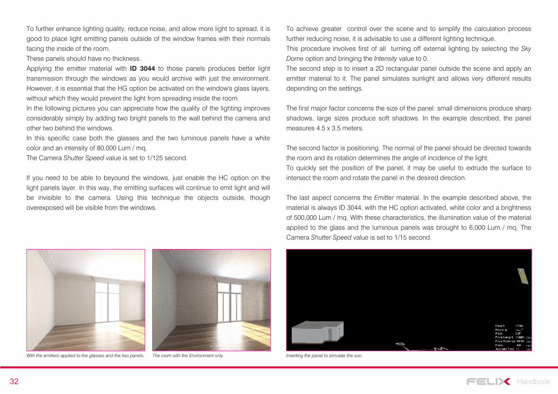
To further enhance lighting quality, reduce noise, and allow more light to spread, it is
good to place light emitting panels outside of the window frames with their normals
facing the inside of the room.
These panels should have no thickness.
Applying the emitter material with ID 3044 to those panels produces better light
transmission through the windows as you would archive with just the environment.
However, it is essential that the HG option be activated on the window's glass layers,
without which they would prevent the light from spreading inside the room.
In the following pictures you can appreciate how the quality of the lighting improves
considerably simply by adding two bright panels to the wall behind the camera and
other two behind the windows.
In this specific case both the glasses and the two luminous panels have a white
color and an intensity of 80,000 Lum / mq.
The Camera Shutter Speed value is set to 1/125 second.
If you need to be able to beyound the windows, just enable the HC option on the
light panels layer. In this way, the emitting surfaces will continue to emit light and will
be invisible to the camera. Using this technique the objects outside, though
overexposed will be visible from the windows.
With the emitters applied to the glasses and the two panels. The room with the Environment only.
To achieve greater control over the scene and to simplify the calculation process
further reducing noise, it is advisable to use a different lighting technique.
This procedure involves first of all turning off external lighting by selecting the Sky
Dome option and bringing the Intensity value to 0.
The second step is to insert a 2D rectangular panel outside the scene and apply an
emitter material to it. The panel simulates sunlight and allows very different results
depending on the settings.
The first major factor concerns the size of the panel: small dimensions produce sharp
shadows, large sizes produce soft shadows. In the example described, the panel
measures 4.5 x 3.5 meters.
The second factor is positioning. The normal of the panel should be directed towards
the room and its rotation determines the angle of incidence of the light.
To quickly set the position of the panel, it may be useful to extrude the surface to
intersect the room and rotate the panel in the desired direction.
The last aspect concerns the Emitter material. In the example described above, the
material is always ID 3044, with the HC option activated, white color and a brightness
of 500,000 Lum / mq. With these characteristics, the illumination value of the material
applied to the glass and the luminous panels was brought to 6,000 Lum / mq. The
Camera Shutter Speed value is set to 1/15 second.
Inserting the panel to simulate the sun.
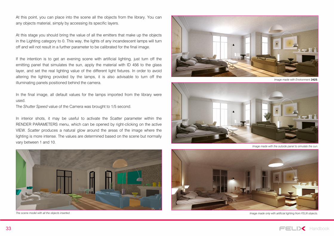
33 Handbook
At this point, you can place into the scene all the objects from the library. You can
any objects material, simply by accessing its specific layers.
At this stage you should bring the value of all the emitters that make up the objects
in the Lighting category to 0. This way, the lights of any incandescent lamps will turn
off and will not result in a further parameter to be calibrated for the final image.
If the intention is to get an evening scene with artificial lighting, just turn off the
emitting panel that simulates the sun, apply the material with ID 456 to the glass
layer, and set the real lighting value of the different light fixtures. In order to avoid
altering the lighting provided by the lamps, it is also advisable to turn off the
illuminating panels positioned behind the camera.
In the final image, all default values for the lamps imported from the library were
used.
The Shutter Speed value of the Camera was brought to 1/5 second.
In interior shots, it may be useful to activate the Scatter parameter within the
RENDER PARAMETERS menu, which can be opened by right-clicking on the active
VIEW. Scatter produces a natural glow around the areas of the image where the
lighting is more intense. The values are determined based on the scene but normally
vary between 1 and 10.
The scene model with all the objects inserted.
Image made with Environment 3425.
Image made with the outside panel to simulate the sun.
Image made only with artificial lighting from FELIX objects.
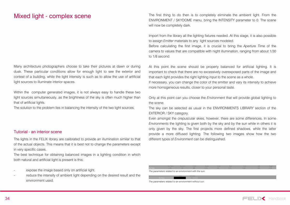
34 Handbook
Mixed light - complex scene
Many architecture photographers choose to take their pictures at dawn or during
dusk. These particular conditions allow for enough light to see the exterior and
context of a building, while the light intensity is such as to allow the use of artificial
light sources to illuminate interior spaces.
Within the computer generated images, it is not always easy to handle these two
light sources simultaneously, as the brightness of the sky is often much higher than
that of artificial lights.
The solution to the problem lies in balancing the intensity of the two light sources.
Tutorial - an interior scene
The lights in the FELIX library are calibrated to provide an illumination similar to that
of the actual objects. This means that it is best not to change the parameters except
in very specific cases.
The best technique for obtaining balanced images in a lighting condition in which
both natural and artificial light is present is this:
- expose the image based only on artificial light.
- reduce the intensity of ambient light depending on the desired result and the
environment used.
The first thing to do then is to completely eliminate the ambient light. From the
ENVIRONMENT / SKYDOME menu, bring the INTENSITY parameter to 0. The scene
will now be completely dark.
Import from the library all the lighting fixtures needed. At this stage, it is also possible
to assign Emitter materials to any light sources modeled.
Before calculating the first image, it is crucial to bring the Aperture Time of the
camera to values that are compatible with night illumination, ranging from about 1/30
to 1/8 second.
At this point the scene should be properly balanced for artificial lighting. It is
important to check that there are no excessively overexposed parts of the image and
that each light provides the right lighting input to the scene as a whole.
If necessary, you can change the color of the emitter and vary its intensity to achieve
more homogeneous results, closer to your personal taste.
Only at this point can you choose the Environment that will provide global lighting to
the scene.
The sky can be selected as usual in the ENVIRONMENTS LIBRARY section of the
EXTERIOR / SKY category.
Even amongst the crepuscular skies, however, there are some differences. In some
Environments the lighting is given both by the sky and by the sun while in others it is
only given by the sky. The first projects more defined shadows, while the latter
provide a more diffused lighting. The following two images show how the two
different types of Environment can be distinguished.
The parameters related to an environment without sun.
The parameters related to an environment with the sun.
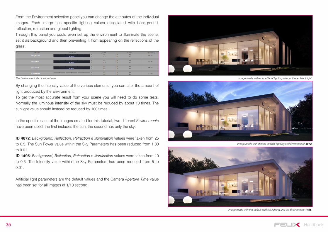
35 Handbook
Image made with only artificial lighting without the ambient light.
Image made with default artificial lighting and Environment 4872.
Image made with the default artificial lighting and the Environment 1495.
From the Environment selection panel you can change the attributes of the individual
images. Each image has specific lighting values associated with background,
reflection, refraction and global lighting.
Through this panel you could even set up the environment to illuminate the scene,
set it as background and then preventing it from appearing on the reflections of the
glass.
The Environment Illumination Panel
By changing the intensity value of the various elements, you can alter the amount of
light produced by the Environment.
To get the most accurate result from your scene you will need to do some tests.
Normally the luminous intensity of the sky must be reduced by about 10 times. The
sunlight value should instead be reduced by 100 times.
In the specific case of the images created for this tutorial, two different Environments
have been used, the first includes the sun, the second has only the sky:
ID 4872: Background, Reflection, Refraction e Illumination values were taken from 25
to 0.5. The Sun Power value within the Sky Parameters has been reduced from 1.30
to 0.01.
ID 1495: Background, Reflection, Refraction e Illumination values were taken from 10
to 0.5. The Intensity value within the Sky Parameters has been reduced from 5 to
0.01.
Artificial light parameters are the default values and the Camera Aperture Time value
has been set for all images at 1/10 second.
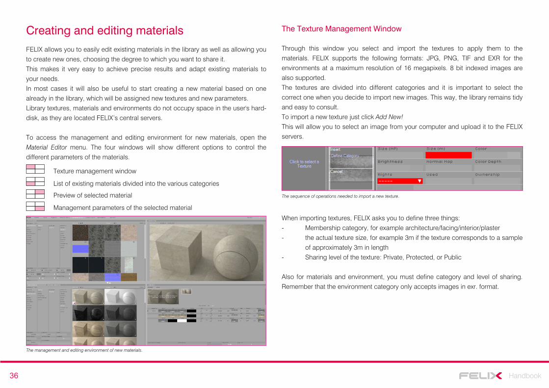
36 Handbook
Creating and editing materialsFELIX allows you to easily edit existing materials in the library as well as allowing you
to create new ones, choosing the degree to which you want to share it.
This makes it very easy to achieve precise results and adapt existing materials to
your needs.
In most cases it will also be useful to start creating a new material based on one
already in the library, which will be assigned new textures and new parameters.
Library textures, materials and environments do not occupy space in the user's hard-
disk, as they are located FELIX’s central servers.
To access the management and editing environment for new materials, open the
Material Editor menu. The four windows will show different options to control the
different parameters of the materials.
Texture management window
List of existing materials divided into the various categories
Preview of selected material
Management parameters of the selected material
The management and editing environment of new materials.
The Texture Management Window
Through this window you select and import the textures to apply them to the
materials. FELIX supports the following formats: JPG, PNG, TIF and EXR for the
environments at a maximum resolution of 16 megapixels. 8 bit indexed images are
also supported.
The textures are divided into different categories and it is important to select the
correct one when you decide to import new images. This way, the library remains tidy
and easy to consult.
To import a new texture just click Add New!
This will allow you to select an image from your computer and upload it to the FELIX
servers.
When importing textures, FELIX asks you to define three things:
- Membership category, for example architecture/facing/interior/plaster
- the actual texture size, for example 3m if the texture corresponds to a sample
of approximately 3m in length
- Sharing level of the texture: Private, Protected, or Public
Also for materials and environment, you must define category and level of sharing.
Remember that the environment category only accepts images in exr. format.
The sequence of operations needed to import a new texture.
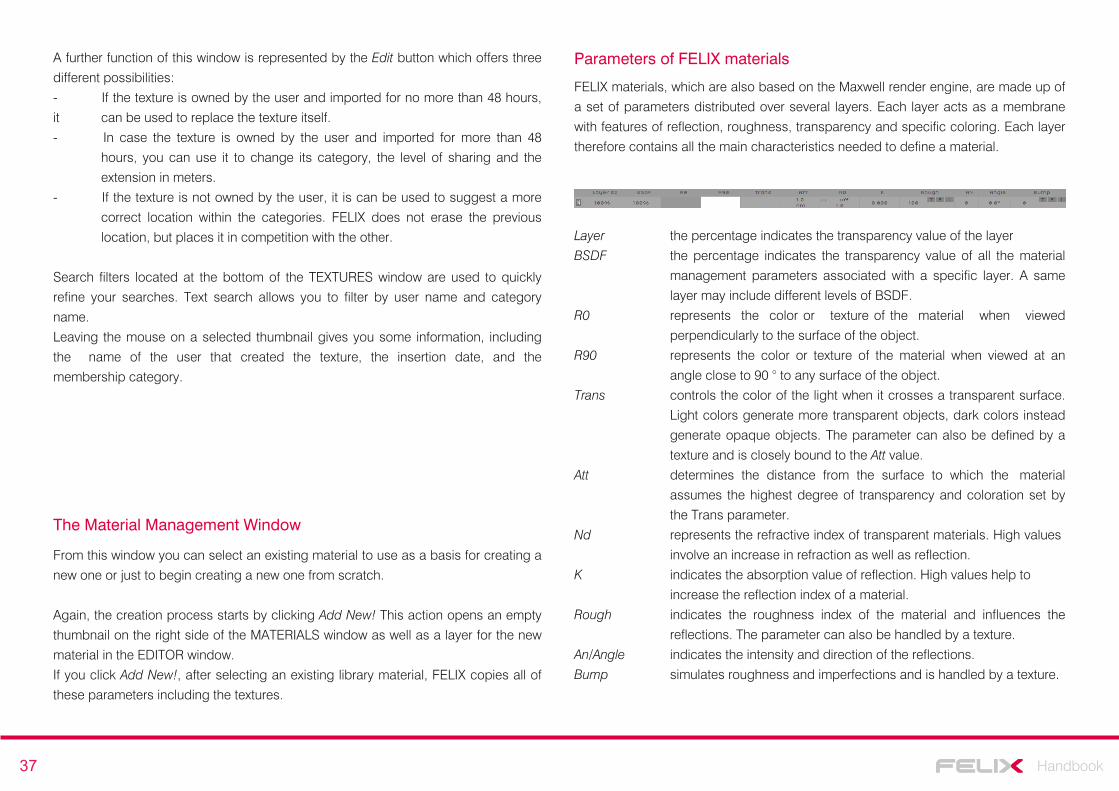
37 Handbook
Parameters of FELIX materials
FELIX materials, which are also based on the Maxwell render engine, are made up of
a set of parameters distributed over several layers. Each layer acts as a membrane
with features of reflection, roughness, transparency and specific coloring. Each layer
therefore contains all the main characteristics needed to define a material.
Layer the percentage indicates the transparency value of the layer
BSDF the percentage indicates the transparency value of all the material
management parameters associated with a specific layer. A same
layer may include different levels of BSDF.
R0 represents the color or texture of the material when viewed
perpendicularly to the surface of the object.
R90 represents the color or texture of the material when viewed at an
angle close to 90 ° to any surface of the object.
Trans controls the color of the light when it crosses a transparent surface.
Light colors generate more transparent objects, dark colors instead
generate opaque objects. The parameter can also be defined by a
texture and is closely bound to the Att value.
Att determines the distance from the surface to which the material
assumes the highest degree of transparency and coloration set by
the Trans parameter.
Nd represents the refractive index of transparent materials. High values
involve an increase in refraction as well as reflection.
K indicates the absorption value of reflection. High values help to
increase the reflection index of a material.
Rough indicates the roughness index of the material and influences the
reflections. The parameter can also be handled by a texture.
An/Angle indicates the intensity and direction of the reflections.
Bump simulates roughness and imperfections and is handled by a texture.
A further function of this window is represented by the Edit button which offers three
different possibilities:
- If the texture is owned by the user and imported for no more than 48 hours,
it can be used to replace the texture itself.
- In case the texture is owned by the user and imported for more than 48
hours, you can use it to change its category, the level of sharing and the
extension in meters.
- If the texture is not owned by the user, it is can be used to suggest a more
correct location within the categories. FELIX does not erase the previous
location, but places it in competition with the other.
Search filters located at the bottom of the TEXTURES window are used to quickly
refine your searches. Text search allows you to filter by user name and category
name.
Leaving the mouse on a selected thumbnail gives you some information, including
the name of the user that created the texture, the insertion date, and the
membership category.
From this window you can select an existing material to use as a basis for creating a
new one or just to begin creating a new one from scratch.
Again, the creation process starts by clicking Add New! This action opens an empty
thumbnail on the right side of the MATERIALS window as well as a layer for the new
material in the EDITOR window.
If you click Add New!, after selecting an existing library material, FELIX copies all of
these parameters including the textures.
The Material Management Window
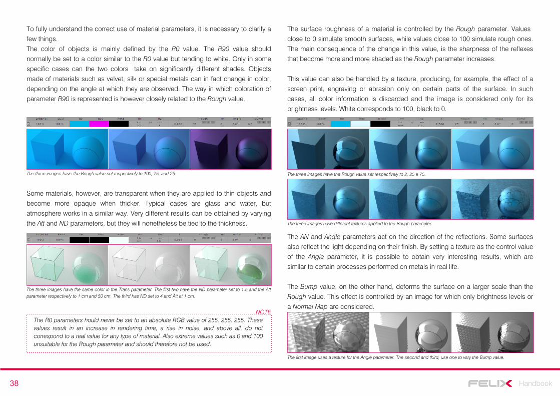
38 Handbook
To fully understand the correct use of material parameters, it is necessary to clarify a
few things.
The color of objects is mainly defined by the R0 value. The R90 value should
normally be set to a color similar to the R0 value but tending to white. Only in some
specific cases can the two colors take on significantly different shades. Objects
made of materials such as velvet, silk or special metals can in fact change in color,
depending on the angle at which they are observed. The way in which coloration of
parameter R90 is represented is however closely related to the Rough value.
The R0 parameters hould never be set to an absolute RGB value of 255, 255, 255. These values result in an increase in rendering time, a rise in noise, and above all, do not correspond to a real value for any type of material. Also extreme values such as 0 and 100 unsuitable for the Rough parameter and should therefore not be used.
NOTE
The three images have the Rough value set respectively to 100, 75, and 25.
Some materials, however, are transparent when they are applied to thin objects and
become more opaque when thicker. Typical cases are glass and water, but
atmosphere works in a similar way. Very different results can be obtained by varying
the Att and ND parameters, but they will nonetheless be tied to the thickness.
The three images have the same color in the Trans parameter. The first two have the ND parameter set to 1.5 and the Att parameter respectively to 1 cm and 50 cm. The third has ND set to 4 and Att at 1 cm.
The surface roughness of a material is controlled by the Rough parameter. Values
close to 0 simulate smooth surfaces, while values close to 100 simulate rough ones.
The main consequence of the change in this value, is the sharpness of the reflexes
that become more and more shaded as the Rough parameter increases.
This value can also be handled by a texture, producing, for example, the effect of a
screen print, engraving or abrasion only on certain parts of the surface. In such
cases, all color information is discarded and the image is considered only for its
brightness levels. White corresponds to 100, black to 0.
The three images have the Rough value set respectively to 2, 25 e 75.
The three images have different textures applied to the Rough parameter.
The AN and Angle parameters act on the direction of the reflections. Some surfaces
also reflect the light depending on their finish. By setting a texture as the control value
of the Angle parameter, it is possible to obtain very interesting results, which are
similar to certain processes performed on metals in real life.
The Bump value, on the other hand, deforms the surface on a larger scale than the
Rough value. This effect is controlled by an image for which only brightness levels or
a Normal Map are considered.
The first image uses a texture for the Angle parameter. The second and third, use one to vary the Bump value.
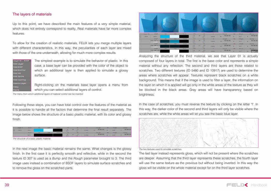
39 Handbook
The layers of materials
Up to this point, we have described the main features of a very simple material,
which does not entirely correspond to reality. Real materials have far more complex
features.
To allow for the creation of realistic materials, FELIX lets you merge multiple layers
with different characteristics. In this way, the peculiarities of each layer are mixed
with those of the one underneath, allowing for much more complex results.
The simplest example is to simulate the behavior of plastic. In this
case, a base layer can be provided with the color of the object to
which an additional layer is then applied to simulate a glossy
surface.
Right-clicking on the materials base layer opens a menu from
which you can select additional layers of control.The menu from which additional layers of material control can be inserted
Following these steps, you can have total control over the features of the material as
it is possible to handle all the factors that determine the final result separately. The
image below shows the structure of a basic plastic material, with its color and glossy
finish.
Analyzing the structure of the third material, we see that Layer 01 is actually
composed of four layers in total. The first is the base color and represents a simple
material without any reflection. The second and third layers are those related to
scratches. Two different textures (ID 5480 and ID 10917) are used to determine the
areas where scratches will appear. Textures represent black scratches on a white
background. This means that if the image is used to filter a layer, the information on
the layer on which it is applied will go only in the white areas of the texture as they will
be blocked in the black areas. Gray areas will have transparency based on
brightness.
In the case of scratches, you must reverse the texture by clicking on the letter "I". In
this way, the darker color of the second and third layers will only be visible where the
scratches are, while the white areas will let you see the basic blue layer.
The last layer instead represents gloss, which will not be present where the scratches
are deeper. Assuming that the third layer represents these scratches, the fourth layer
will use the same texture as the previous but without being inverted. In this way the
gloss will be visible on the whole material except for on the third layer scratches.
In the next image the basic material remains the same. What changes is the glossy
finish. In the first case it is perfectly smooth and reflective, while in the second the
texture ID 307 is used as a Bump and the Rough parameter brought to 3. The third
image uses instead a combination of BSDF layers to simulate surface scratches and
to remove the gloss on the scratched parts.
The structure of a basic plastic material.
The two textures used to simulate scratches.
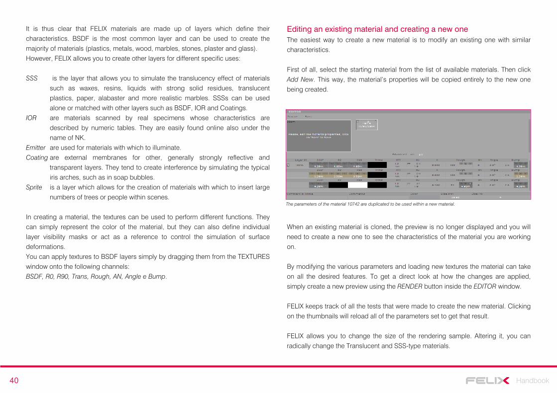
40 Handbook
Editing an existing material and creating a new oneThe easiest way to create a new material is to modify an existing one with similar
characteristics.
First of all, select the starting material from the list of available materials. Then click
Add New. This way, the material’s properties will be copied entirely to the new one
being created.
The parameters of the material 10742 are duplicated to be used within a new material.
When an existing material is cloned, the preview is no longer displayed and you will
need to create a new one to see the characteristics of the material you are working
on.
By modifying the various parameters and loading new textures the material can take
on all the desired features. To get a direct look at how the changes are applied,
simply create a new preview using the RENDER button inside the EDITOR window.
FELIX keeps track of all the tests that were made to create the new material. Clicking
on the thumbnails will reload all of the parameters set to get that result.
FELIX allows you to change the size of the rendering sample. Altering it, you can
radically change the Translucent and SSS-type materials.
It is thus clear that FELIX materials are made up of layers which define their
characteristics. BSDF is the most common layer and can be used to create the
majority of materials (plastics, metals, wood, marbles, stones, plaster and glass).
However, FELIX allows you to create other layers for different specific uses:
SSS is the layer that allows you to simulate the translucency effect of materials
such as waxes, resins, liquids with strong solid residues, translucent
plastics, paper, alabaster and more realistic marbles. SSSs can be used
alone or matched with other layers such as BSDF, IOR and Coatings.
IOR are materials scanned by real specimens whose characteristics are
described by numeric tables. They are easily found online also under the
name of NK.
Emitter are used for materials with which to illuminate.
Coating are external membranes for other, generally strongly reflective and
transparent layers. They tend to create interference by simulating the typical
iris arches, such as in soap bubbles.
Sprite is a layer which allows for the creation of materials with which to insert large
numbers of trees or people within scenes.
In creating a material, the textures can be used to perform different functions. They
can simply represent the color of the material, but they can also define individual
layer visibility masks or act as a reference to control the simulation of surface
deformations.
You can apply textures to BSDF layers simply by dragging them from the TEXTURES
window onto the following channels:
BSDF, R0, R90, Trans, Rough, AN, Angle e Bump.
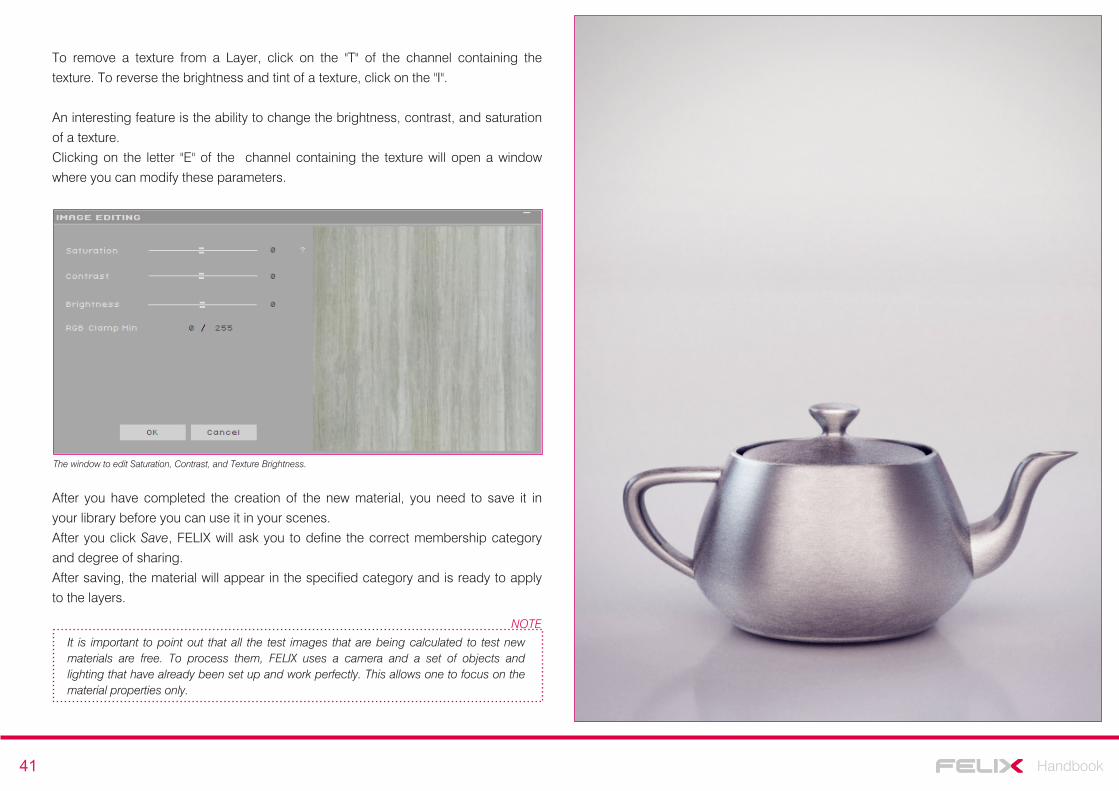
41 Handbook
To remove a texture from a Layer, click on the "T" of the channel containing the
texture. To reverse the brightness and tint of a texture, click on the "I".
An interesting feature is the ability to change the brightness, contrast, and saturation
of a texture.
Clicking on the letter "E" of the channel containing the texture will open a window
where you can modify these parameters.
The window to edit Saturation, Contrast, and Texture Brightness.
After you have completed the creation of the new material, you need to save it in
your library before you can use it in your scenes.
After you click Save, FELIX will ask you to define the correct membership category
and degree of sharing.
After saving, the material will appear in the specified category and is ready to apply
to the layers.
It is important to point out that all the test images that are being calculated to test new materials are free. To process them, FELIX uses a camera and a set of objects and lighting that have already been set up and work perfectly. This allows one to focus on the material properties only.
NOTE
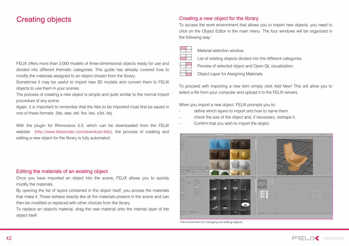
42 Handbook
Creating objects
FELIX offers more than 3,000 models of three-dimensional objects ready for use and
divided into different thematic categories. This guide has already covered how to
modify the materials assigned to an object chosen from the library.
Sometimes it may be useful to import new 3D models and convert them to FELIX
objects to use them in your scenes.
The process of creating a new object is simple and quite similar to the normal import
procedure of any scene.
Again, it is important to remember that the files to be imported must first be saved in
one of these formats: 3ds, dae, dxf, fbx, lwo, o3d, obj.
With the plugin for Rhinoceros 5.0, which can be downloaded from the FELIX
website (http://www.felixrender.com/download-felix), the process of creating and
editing a new object for the library is fully automated.
Editing the materials of an existing objectOnce you have imported an object into the scene, FELIX allows you to quickly
modify the materials.
By opening the list of layers contained in the object itself, you access the materials
that make it. These behave exactly like all the materials present in the scene and can
then be modified or replaced with other choices from the library.
To replace an object's material, drag the new material onto the internal layer of the
object itself.
Creating a new object for the libraryTo access the work environment that allows you to import new objects, you need to
click on the Object Editor in the main menu. The four windows will be organized in
the following way:
Material selection window.
List of existing objects divided into the different categories.
Preview of selected object and Open GL visualization.
Object Layer for Assigning Materials.
The environment for managing and editing objects.
To proceed with importing a new item simply click Add New! This will allow you to
select a file from your computer and upload it to the FELIX servers.
When you import a new object, FELIX prompts you to:
- define which layers to import and how to name them.
- check the size of the object and, if necessary, reshape it.
- Confirm that you wish to import the object.
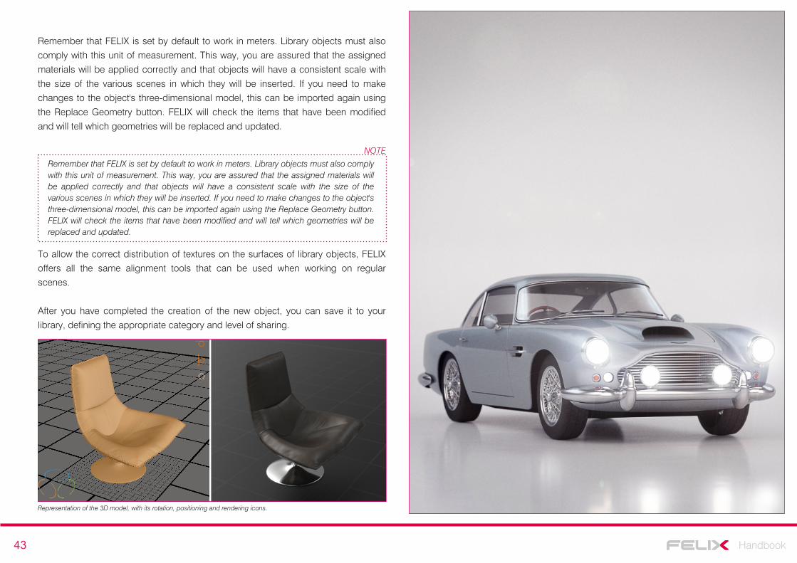
43 Handbook
Remember that FELIX is set by default to work in meters. Library objects must also
comply with this unit of measurement. This way, you are assured that the assigned
materials will be applied correctly and that objects will have a consistent scale with
the size of the various scenes in which they will be inserted. If you need to make
changes to the object's three-dimensional model, this can be imported again using
the Replace Geometry button. FELIX will check the items that have been modified
and will tell which geometries will be replaced and updated.
Remember that FELIX is set by default to work in meters. Library objects must also comply with this unit of measurement. This way, you are assured that the assigned materials will be applied correctly and that objects will have a consistent scale with the size of the various scenes in which they will be inserted. If you need to make changes to the object's three-dimensional model, this can be imported again using the Replace Geometry button. FELIX will check the items that have been modified and will tell which geometries will be replaced and updated.
NOTE
To allow the correct distribution of textures on the surfaces of library objects, FELIX
offers all the same alignment tools that can be used when working on regular
scenes.
After you have completed the creation of the new object, you can save it to your
library, defining the appropriate category and level of sharing.
Representation of the 3D model, with its rotation, positioning and rendering icons.
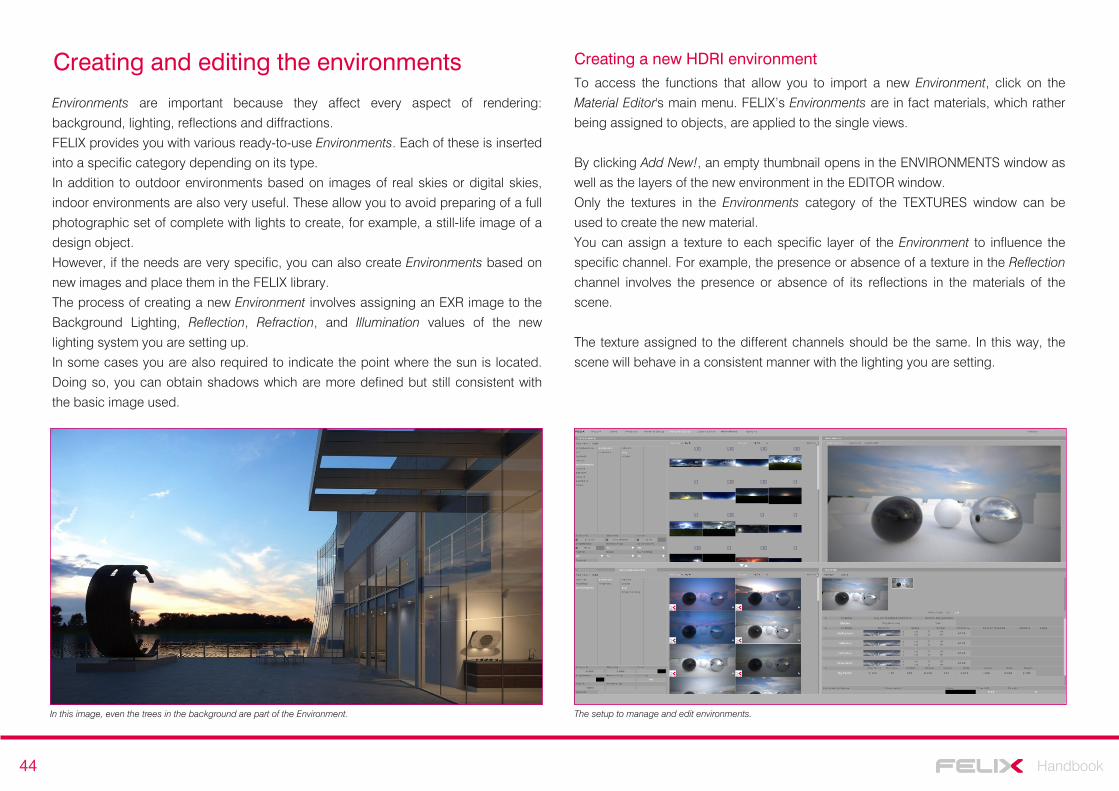
44 Handbook
Creating and editing the environments
Environments are important because they affect every aspect of rendering:
background, lighting, reflections and diffractions.
FELIX provides you with various ready-to-use Environments. Each of these is inserted
into a specific category depending on its type.
In addition to outdoor environments based on images of real skies or digital skies,
indoor environments are also very useful. These allow you to avoid preparing of a full
photographic set of complete with lights to create, for example, a still-life image of a
design object.
However, if the needs are very specific, you can also create Environments based on
new images and place them in the FELIX library.
The process of creating a new Environment involves assigning an EXR image to the
Background Lighting, Reflection, Refraction, and Illumination values of the new
lighting system you are setting up.
In some cases you are also required to indicate the point where the sun is located.
Doing so, you can obtain shadows which are more defined but still consistent with
the basic image used.
Creating a new HDRI environmentTo access the functions that allow you to import a new Environment, click on the
Material Editor's main menu. FELIX’s Environments are in fact materials, which rather
being assigned to objects, are applied to the single views.
By clicking Add New!, an empty thumbnail opens in the ENVIRONMENTS window as
well as the layers of the new environment in the EDITOR window.
Only the textures in the Environments category of the TEXTURES window can be
used to create the new material.
You can assign a texture to each specific layer of the Environment to influence the
specific channel. For example, the presence or absence of a texture in the Reflection
channel involves the presence or absence of its reflections in the materials of the
scene.
The texture assigned to the different channels should be the same. In this way, the
scene will behave in a consistent manner with the lighting you are setting.
The setup to manage and edit environments.In this image, even the trees in the background are part of the Environment.
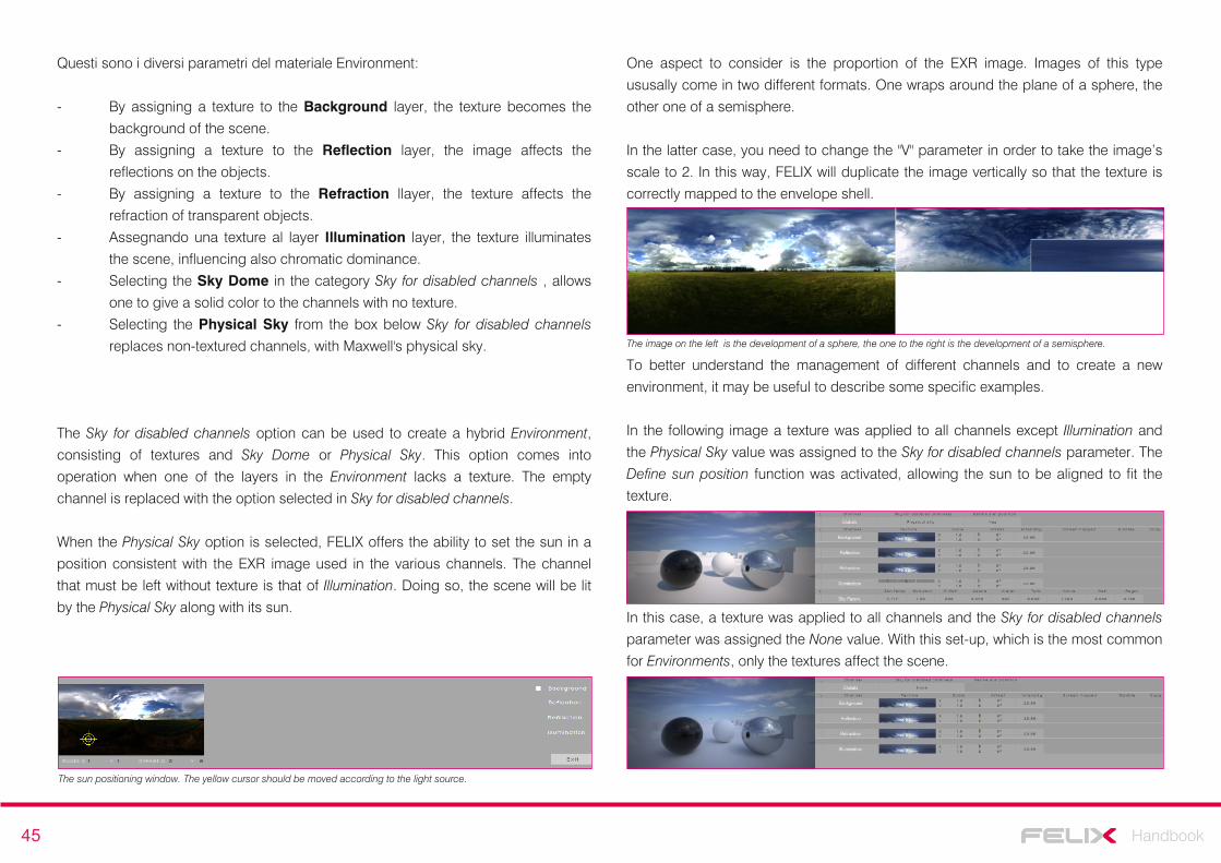
45 Handbook
Questi sono i diversi parametri del materiale Environment:
- By assigning a texture to the Background layer, the texture becomes the
background of the scene.
- By assigning a texture to the Reflection layer, the image affects the
reflections on the objects.
- By assigning a texture to the Refraction llayer, the texture affects the
refraction of transparent objects.
- Assegnando una texture al layer Illumination layer, the texture illuminates
the scene, influencing also chromatic dominance.
- Selecting the Sky Dome in the category Sky for disabled channels , allows
one to give a solid color to the channels with no texture.
- Selecting the Physical Sky from the box below Sky for disabled channels
replaces non-textured channels, with Maxwell's physical sky.
The Sky for disabled channels option can be used to create a hybrid Environment,
consisting of textures and Sky Dome or Physical Sky. This option comes into
operation when one of the layers in the Environment lacks a texture. The empty
channel is replaced with the option selected in Sky for disabled channels.
When the Physical Sky option is selected, FELIX offers the ability to set the sun in a
position consistent with the EXR image used in the various channels. The channel
that must be left without texture is that of Illumination. Doing so, the scene will be lit
by the Physical Sky along with its sun.
The sun positioning window. The yellow cursor should be moved according to the light source.
One aspect to consider is the proportion of the EXR image. Images of this type
ususally come in two different formats. One wraps around the plane of a sphere, the
other one of a semisphere.
In the latter case, you need to change the "V" parameter in order to take the image’s
scale to 2. In this way, FELIX will duplicate the image vertically so that the texture is
correctly mapped to the envelope shell.
The image on the left is the development of a sphere, the one to the right is the development of a semisphere.
To better understand the management of different channels and to create a new
environment, it may be useful to describe some specific examples.
In the following image a texture was applied to all channels except Illumination and
the Physical Sky value was assigned to the Sky for disabled channels parameter. The
Define sun position function was activated, allowing the sun to be aligned to fit the
texture.
In this case, a texture was applied to all channels and the Sky for disabled channels
parameter was assigned the None value. With this set-up, which is the most common
for Environments, only the textures affect the scene.
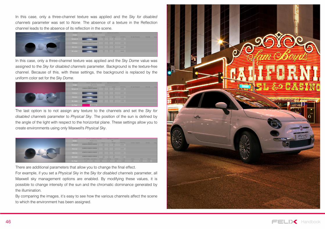
46 Handbook
In this case, only a three-channel texture was applied and the Sky for disabled
channels parameter was set to None. The absence of a texture in the Reflection
channel leads to the absence of its reflection in the scene.
In this case, only a three-channel texture was applied and the Sky Dome value was
assigned to the Sky for disabled channels parameter. Background is the texture-free
channel. Because of this, with these settings, the background is replaced by the
uniform color set for the Sky Dome.
The last option is to not assign any texture to the channels and set the Sky for
disabled channels parameter to Physical Sky. The position of the sun is defined by
the angle of the light with respect to the horizontal plane. These settings allow you to
create environments using only Maxwell's Physical Sky.
There are additional parameters that allow you to change the final effect.
For example, if you set a Physical Sky in the Sky for disabled channels parameter, all
Maxwell sky management options are enabled. By modifying these values, it is
possible to change intensity of the sun and the chromatic dominance generated by
the illumination.
By comparing the images, it’s easy to see how the various channels affect the scene
to which the environment has been assigned.
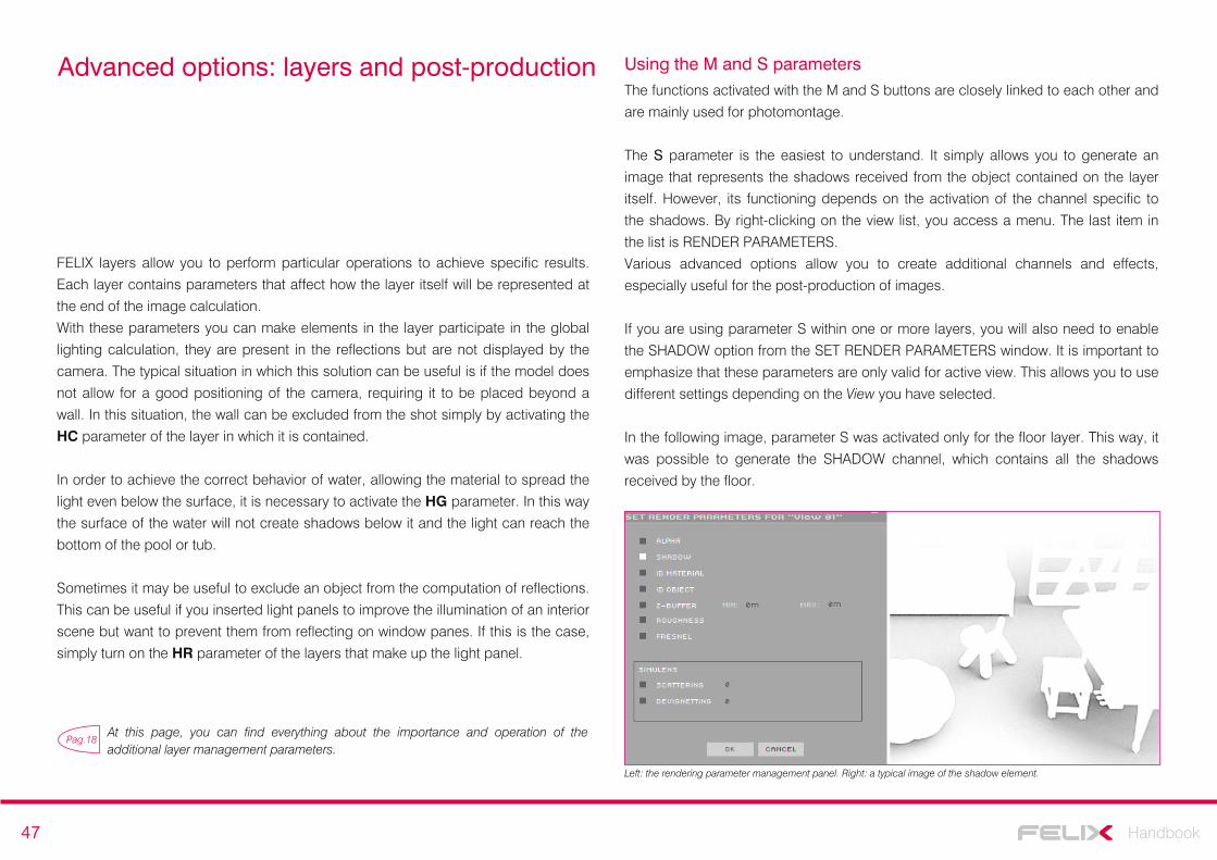
47 Handbook
Advanced options: layers and post-production
FELIX layers allow you to perform particular operations to achieve specific results.
Each layer contains parameters that affect how the layer itself will be represented at
the end of the image calculation.
With these parameters you can make elements in the layer participate in the global
lighting calculation, they are present in the reflections but are not displayed by the
camera. The typical situation in which this solution can be useful is if the model does
not allow for a good positioning of the camera, requiring it to be placed beyond a
wall. In this situation, the wall can be excluded from the shot simply by activating the
HC parameter of the layer in which it is contained.
In order to achieve the correct behavior of water, allowing the material to spread the
light even below the surface, it is necessary to activate the HG parameter. In this way
the surface of the water will not create shadows below it and the light can reach the
bottom of the pool or tub.
Sometimes it may be useful to exclude an object from the computation of reflections.
This can be useful if you inserted light panels to improve the illumination of an interior
scene but want to prevent them from reflecting on window panes. If this is the case,
simply turn on the HR parameter of the layers that make up the light panel.
Pag.18At this page, you can find everything about the importance and operation of the additional layer management parameters.
Using the M and S parameters The functions activated with the M and S buttons are closely linked to each other and
are mainly used for photomontage.
The S parameter is the easiest to understand. It simply allows you to generate an
image that represents the shadows received from the object contained on the layer
itself. However, its functioning depends on the activation of the channel specific to
the shadows. By right-clicking on the view list, you access a menu. The last item in
the list is RENDER PARAMETERS.
Various advanced options allow you to create additional channels and effects,
especially useful for the post-production of images.
If you are using parameter S within one or more layers, you will also need to enable
the SHADOW option from the SET RENDER PARAMETERS window. It is important to
emphasize that these parameters are only valid for active view. This allows you to use
different settings depending on the View you have selected.
In the following image, parameter S was activated only for the floor layer. This way, it
was possible to generate the SHADOW channel, which contains all the shadows
received by the floor.
Left: the rendering parameter management panel. Right: a typical image of the shadow element.
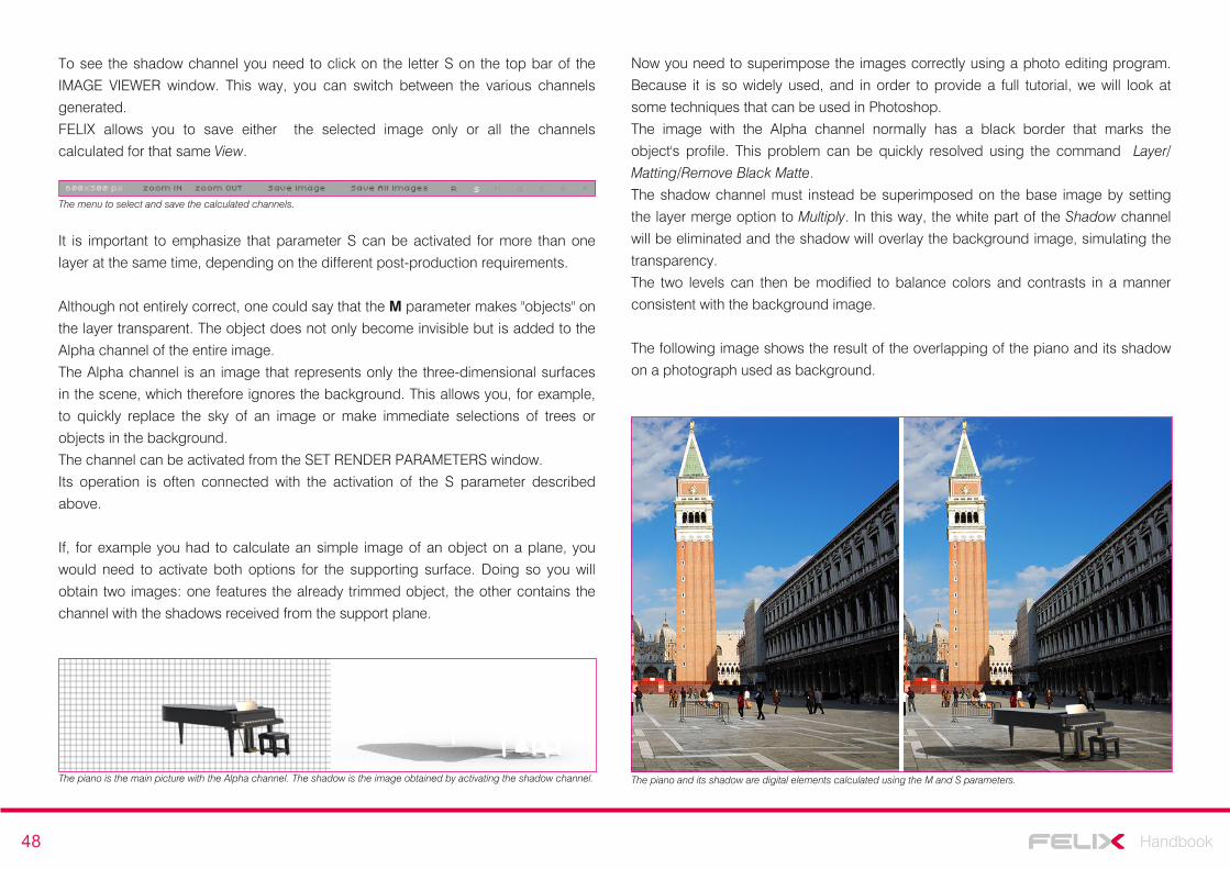
48 Handbook
The piano and its shadow are digital elements calculated using the M and S parameters.
To see the shadow channel you need to click on the letter S on the top bar of the
IMAGE VIEWER window. This way, you can switch between the various channels
generated.
FELIX allows you to save either the selected image only or all the channels
calculated for that same View.
The menu to select and save the calculated channels.
It is important to emphasize that parameter S can be activated for more than one
layer at the same time, depending on the different post-production requirements.
Although not entirely correct, one could say that the M parameter makes "objects" on
the layer transparent. The object does not only become invisible but is added to the
Alpha channel of the entire image.
The Alpha channel is an image that represents only the three-dimensional surfaces
in the scene, which therefore ignores the background. This allows you, for example,
to quickly replace the sky of an image or make immediate selections of trees or
objects in the background.
The channel can be activated from the SET RENDER PARAMETERS window.
Its operation is often connected with the activation of the S parameter described
above.
If, for example you had to calculate an simple image of an object on a plane, you
would need to activate both options for the supporting surface. Doing so you will
obtain two images: one features the already trimmed object, the other contains the
channel with the shadows received from the support plane.
Now you need to superimpose the images correctly using a photo editing program.
Because it is so widely used, and in order to provide a full tutorial, we will look at
some techniques that can be used in Photoshop.
The image with the Alpha channel normally has a black border that marks the
object's profile. This problem can be quickly resolved using the command Layer/
Matting/Remove Black Matte.
The shadow channel must instead be superimposed on the base image by setting
the layer merge option to Multiply. In this way, the white part of the Shadow channel
will be eliminated and the shadow will overlay the background image, simulating the
transparency.
The two levels can then be modified to balance colors and contrasts in a manner
consistent with the background image.
The following image shows the result of the overlapping of the piano and its shadow
on a photograph used as background.
The piano is the main picture with the Alpha channel. The shadow is the image obtained by activating the shadow channel.
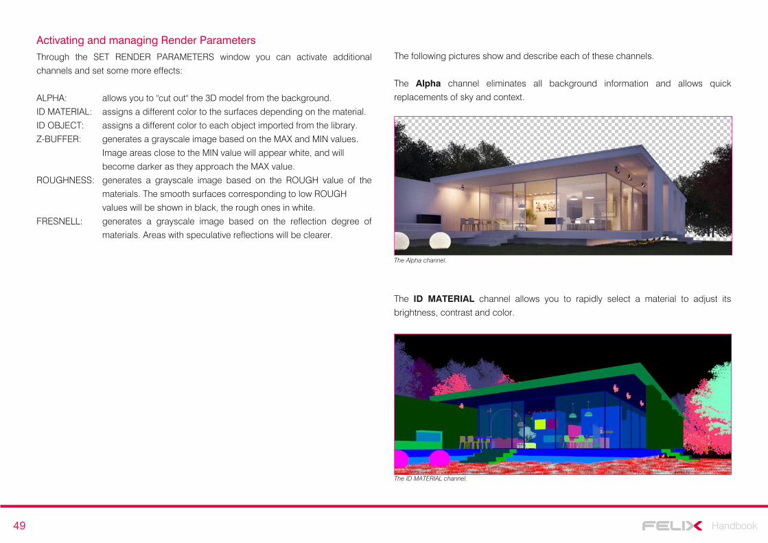
49 Handbook
Activating and managing Render ParametersThrough the SET RENDER PARAMETERS window you can activate additional
channels and set some more effects:
ALPHA: allows you to "cut out" the 3D model from the background.
ID MATERIAL: assigns a different color to the surfaces depending on the material.
ID OBJECT: assigns a different color to each object imported from the library.
Z-BUFFER: generates a grayscale image based on the MAX and MIN values.
Image areas close to the MIN value will appear white, and will
become darker as they approach the MAX value.
ROUGHNESS: generates a grayscale image based on the ROUGH value of the
materials. The smooth surfaces corresponding to low ROUGH
values will be shown in black, the rough ones in white.
FRESNELL: generates a grayscale image based on the reflection degree of
materials. Areas with speculative reflections will be clearer.
The Alpha channel.
The ID MATERIAL channel allows you to rapidly select a material to adjust its
brightness, contrast and color.
The ID MATERIAL channel.
The following pictures show and describe each of these channels.
The Alpha channel eliminates all background information and allows quick
replacements of sky and context.
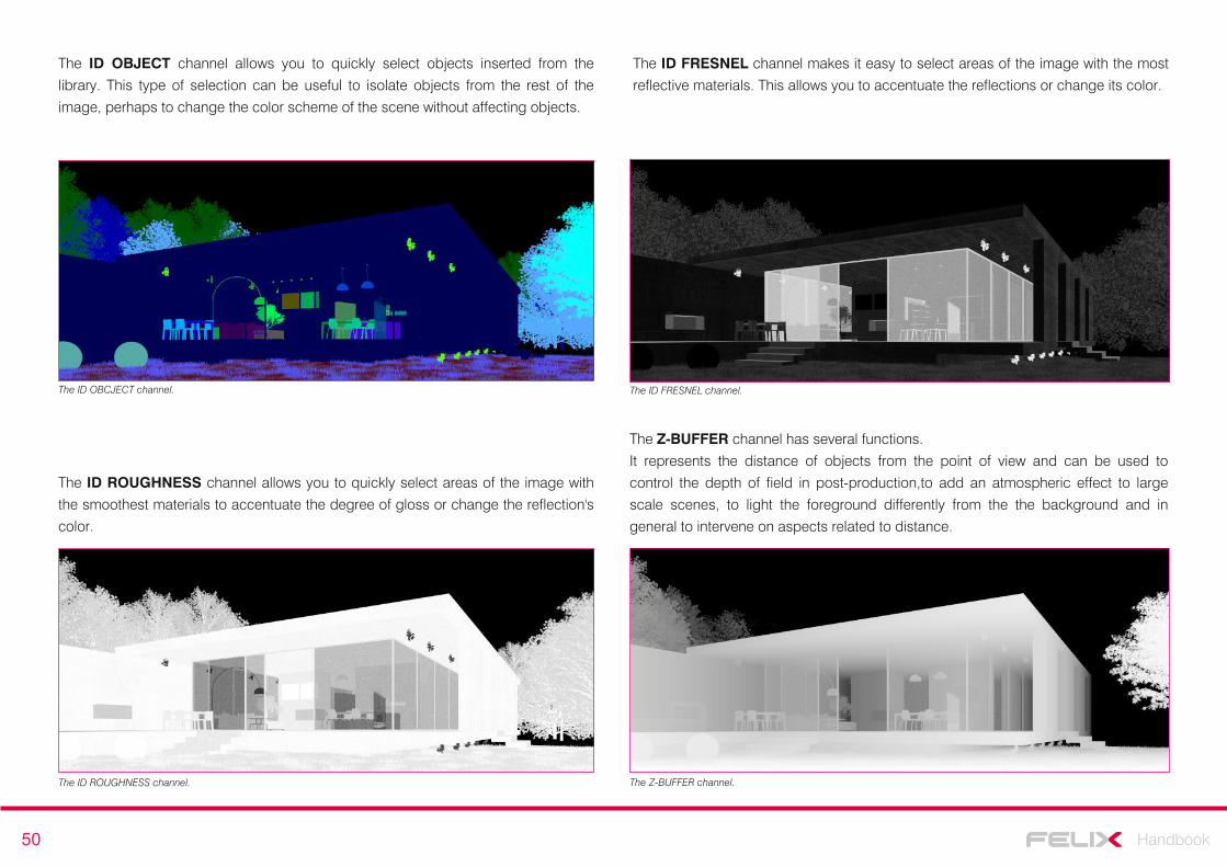
50 Handbook
The ID ROUGHNESS channel allows you to quickly select areas of the image with
the smoothest materials to accentuate the degree of gloss or change the reflection's
color.
The ID ROUGHNESS channel.
The ID FRESNEL channel makes it easy to select areas of the image with the most
reflective materials. This allows you to accentuate the reflections or change its color.
The ID FRESNEL channel.
The Z-BUFFER channel has several functions.
It represents the distance of objects from the point of view and can be used to
control the depth of field in post-production,to add an atmospheric effect to large
scale scenes, to light the foreground differently from the the background and in
general to intervene on aspects related to distance.
The Z-BUFFER channel.
The ID OBCJECT channel.
The ID OBJECT channel allows you to quickly select objects inserted from the
library. This type of selection can be useful to isolate objects from the rest of the
image, perhaps to change the color scheme of the scene without affecting objects.
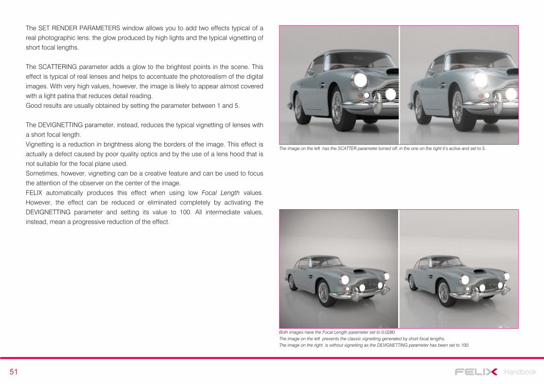
51 Handbook
The image on the left has the SCATTER parameter turned off, in the one on the right it’s active and set to 5.
The SET RENDER PARAMETERS window allows you to add two effects typical of a
real photographic lens: the glow produced by high lights and the typical vignetting of
short focal lengths.
The SCATTERING parameter adds a glow to the brightest points in the scene. This
effect is typical of real lenses and helps to accentuate the photorealism of the digital
images. With very high values, however, the image is likely to appear almost covered
with a light patina that reduces detail reading.
Good results are usually obtained by setting the parameter between 1 and 5.
The DEVIGNETTING parameter, instead, reduces the typical vignetting of lenses with
a short focal length.
Vignetting is a reduction in brightness along the borders of the image. This effect is
actually a defect caused by poor quality optics and by the use of a lens hood that is
not suitable for the focal plane used.
Sometimes, however, vignetting can be a creative feature and can be used to focus
the attention of the observer on the center of the image.
FELIX automatically produces this effect when using low Focal Length values.
However, the effect can be reduced or eliminated completely by activating the
DEVIGNETTING parameter and setting its value to 100. All intermediate values,
instead, mean a progressive reduction of the effect.
Both images have the Focal Length parameter set to 0.0280.The image on the left presents the classic vignetting generated by short focal lengths.The image on the right is without vignetting as the DEVIGNETTING parameter has been set to 100.
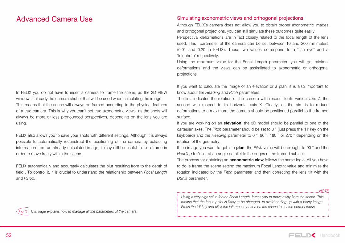
52 Handbook
Advanced Camera Use
In FELIX you do not have to insert a camera to frame the scene, as the 3D VIEW
window is already the camera shutter that will be used when calculating the image.
This means that the scene will always be framed according to the physical features
of a true camera. This is why you can’t set true axonometric views, as the shots will
always be more or less pronounced perspectives, depending on the lens you are
using.
FELIX also allows you to save your shots with different settings. Although it is always
possible to automatically reconstruct the positioning of the camera by extracting
information from an already calculated image, it may still be useful to fix a frame in
order to move freely within the scene.
FELIX automatically and accurately calculates the blur resulting from to the depth of
field . To control it, it is crucial to understand the relationship between Focal Length
and FStop.
Pag.13 This page explains how to manage all the parameters of the camera.
Simulating axonometric views and orthogonal projectionsAlthough FELIX’s camera does not allow you to obtain proper axonometric images
and orthogonal projections, you can still simulate these outcomes quite easily.
Perspectival deformations are in fact closely related to the focal length of the lens
used. This parameter of the camera can be set between 10 and 200 millimeters
(0.01 and 0.20 in FELIX). These two values correspond to a "fish eye" and a
"telephoto" respectively.
Using the maximum value for the Focal Length parameter, you will get minimal
deformations and the views can be assimilated to axonometric or orthogonal
projections.
If you want to calculate the image of an elevation or a plan, it is also important to
know about the Heading and Pitch parameters.
The first indicates the rotation of the camera with respect to its vertical axis Z, the
second with respect to its horizontal axis X. Clearly, as the aim is to reduce
deformations to a maximum, the camera should be positioned parallel to the framed
surface.
If you are working on an elevation, the 3D model should be parallel to one of the
cartesian axes. The Pitch parameter should be set to 0 ° (just press the "H" key on the
keyboard) and the Heading parameter to 0 °, 90 °, 180 ° or 270 ° depending on the
rotation of the geometry.
If the image you want to get is a plan, the Pitch value will be brought to 90 ° and the
Heading to 0 ° or at an angle parallel to the edges of the framed subject.
The process for obtaining an axonometric view follows the same logic. All you have
to do is frame the scene setting the maximum Focal Lengtht value and minimize the
rotation indicated by the Pitch parameter and then correcting the lens tilt with the
DShift parameter.
Using a very high value for the Focal Length, forces you to move away from the scene. This means that the focus point is likely to be changed, to avoid ending up with a blurry image. Press the "d" key and click the left mouse button on the scene to set the correct focus.
NOTE
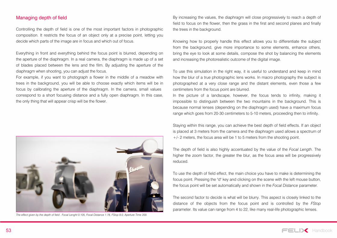
53 Handbook
Controlling the depth of field is one of the most important factors in photographic
composition. It restricts the focus of an object only at a precise point, letting you
decide which parts of the image are in focus and which out of focus.
Everything in front and everything behind the focus point is blurred, depending on
the aperture of the diaphragm. In a real camera, the diaphragm is made up of a set
of blades placed between the lens and the film. By adjusting the aperture of the
diaphragm when shooting, you can adjust the focus.
For example, if you want to photograph a flower in the middle of a meadow with
trees in the background, you will be able to choose exactly which items will be in
focus by calibrating the aperture of the diaphragm. In the camera, small values
correspond to a short focusing distance and a fully open diaphragm. In this case,
the only thing that will appear crisp will be the flower.
Managing depth of field By increasing the values, the diaphragm will close progressively to reach a depth of
field to focus on the flower, then the grass in the first and second planes and finally
the trees in the background.
Knowing how to properly handle this effect allows you to differentiate the subject
from the background, give more importance to some elements, enhance others,
bring the eye to look at some details, compose the shot by balancing the elements
and increasing the photorealistic outcome of the digital image.
To use this simulation in the right way, it is useful to understand and keep in mind
how the blur of a true photographic lens works. In macro photography the subject is
photographed at a very close range and the distant elements, even those a few
centimeters from the focus point are blurred.
In the picture of a landscape, however, the focus tends to infinity, making it
impossible to distinguish between the two mountains in the background. This is
because normal lenses (depending on the diaphragm used) have a maximum focus
range which goes from 20-30 centimeters to 5-10 meters, proceeding then to infinity.
Staying within this range, you can achieve the best depth of field effects. If an object
is placed at 3 meters from the camera and the diaphragm used allows a spectrum of
+/- 2 meters, the focus area will be 1 to 5 meters from the shooting point.
The depth of field is also highly accentuated by the value of the Focal Length. The
higher the zoom factor, the greater the blur, as the focus area will be progressively
reduced.
To use the depth of field effect, the main choice you have to make is determining the
focus point. Pressing the "d" key and clicking on the scene with the left mouse button,
the focus point will be set automatically and shown in the Focal Distance parameter.
The second factor to decide is what will be blurry. This aspect is closely linked to the
distance of the objects from the focus point and is controlled by the FStop
parameter. Its value can range from 4 to 22, like many real-life photographic lenses.The effect given by the depth of field . Focal Lenght 0.105, Focal Distance 1.78, FStop 8.0, Aperture Time 200.
54 Handbook
Lower values produce more blur, higher values tend to reduce it. This effect is quite
simple to achieve but requires different calibrations. It is therefore normal to have to
do some attempts before getting the desired effect. Increasing the rendering quality
also improves the gradient of blur.
In a real camera, the FStop value affects the size of the shutter during shooting.
When using a low value, the lens blades do not close completely and leave more
light, producing however a lesser area of focus. This means that the shutter speed
can be quite short, as the shutter will let in a lot of light.
If a high value for the FStop parameter, exactly the opposite will occur and the
Aperture Time value needs to be increased. This way, the blades will remain open
for more time during the shutter phase, and thus it may allow more light to enter
even if the shutter is quite closed.
Finding the right balance between these two parameters may seem complicated,
but it's actually a fairly simple operation.
It is best to start with using the minimum value (4.0) for the FStop parameter. Then
change the exposure time by calibrating the Aperture Time value.
At this point, you can modify the FStop value as desired by following this rule: for
each of its incremental clicks you have to compensate with a slowdown of the
aperture time.
For example, if FStop is 4.0 and Aperture Time 800, you will get a good exposure but
too little depth of field, you will get the same exposure and depth of field using a
FStop value of 12.0 and an Aperture Time at 80 . Both values have been moved by
10 clicks.
Managing the FStop/Aperture Time ratio.
This is made easy with Camera Match operation. This procedure allows you to match
the position of the digital camera with that of the camera that took the picture of the
context.
It is not an automated procedure, but you can get excellent results using it.
First of all, remembered that by opening the properties of a digital photograph,
usually you can find the shutter parameters. The image used in this example has
been produced by a Nikon D40 with a focal length of 18mm.
Digital cameras normally have a known conversion factor, depending on the size of
the CCD sensor, to relate their focal distance to that of an analogue lens. In this case
the multiplication factor is 1.5. This means that the corresponding analog target
would be a 27mm. The Focal Length of the FELIX camera then, should be set to
0.027.
By right-clicking in the 3D VIEW window you can set an image as the background of
the viewport. Then select the background image and accept the proposed aspect
ratio change.
Camera match and set background image
The FELIX camera has been set up with the same camera values as the real camera.People in the foreground and the blue surface are digital elements. The view is that of the 3D VIEW.
One of the most common operations when performing architectural representations
is that of overlaying a digital image onto a real photograph.
This way, you can place an object realized with computer graphics in a real context.
55 Handbook
Optimizing the use of credits
FELIX is a software that allows you to create digital images quickly and
economically. To achieve convincing results investing a small amount of credits, it is
advisable to follow certain guidelines.
First of all, avoid calculating high resolution images if you are still proceeding with
the initial calibration. The parameters of each scene need to be set through some
test images. From these you can evaluate important aspects, such as whether the
lighting works properly, if the materials behave as desired and if there are
overexposed or dark areas in the image.
It is also essential to work with specific models, which are consistent with the views
that are being realized. It would certainly not be easy to produce a good image of a
detail in a room, which in turn is embedded in a complete building, perhaps even
surrounded by vegetation and complex exterior spaces.
Much of the calculation would be "wasted" on computing elements totally unrelated
to the view you want to obtain. This means that both the quality and the calculation
time must be increased.
If, instead, the hypothetical room is extracted from the general model and lighting is
set only for that specific view, the calculation time will drastically decrease and you
will not have to use too high a quality for the final image, as the calculation will be
dedicated entirely to the framed objects.
Working in this way therefore ensures shorter rendering time and more savings in
credits, as you can use lower quality levels.
Each scene requires the processing of a set of tests before it can calculate the final
image. With these intermediate drafts countless aspects of the general image can be
controlled without having to set a high rendering quality. Analyzing the drafts can
significantly improve the final result by investing only a minimum amount of credits.
Firstly, one should emphasize that tests should be made using the smallest possible
size in relation to the proportions of the image being calculated.
The default size suggested by FELIX is 800x400 pixels, corresponding to a 2: 1 ratio.
Images for tests can be calculated using a lower resolution. The minimum size for
this ratio is 550x275 pixels.
If the size of the image were left with the basic settings also to calculate the draft
images, 0.25 credits would be used. By reducing the resolution, however, you can
immediately bring the consumption of credits to 0.12.
If you decide to use different proportions, you must determine the minimum size that
can be used for testing in this way:
- open the EDIT RESOLUTION panel with a double click on the size that is set
for the current View.
- set the pixel size of the image by entering the values within the Width and
Height parameters.
- gradually reduce the Width value. The Height value will be automatically
modified to a minimum overall size of 0.15 Megapixels.
At this point, you can be sure that you have set the lowest possible resolution for your
tests, with a consequent reduction in credit consumption.
Images for tests: resolution and quality
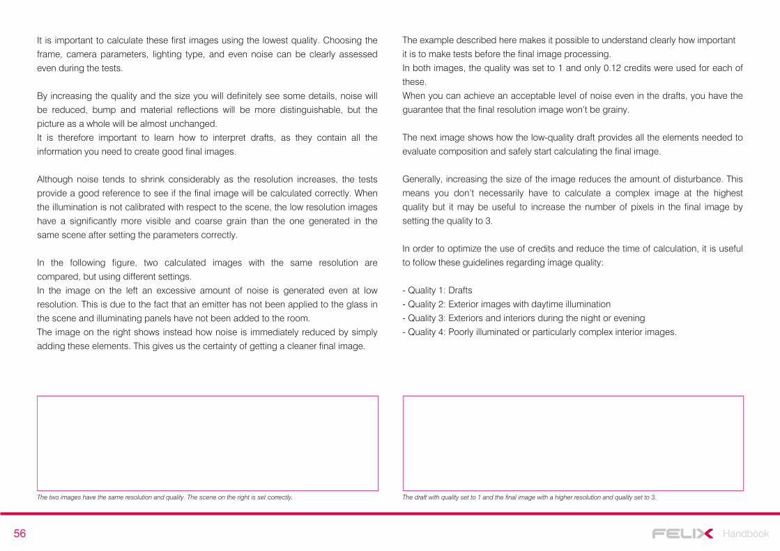
56 Handbook
It is important to calculate these first images using the lowest quality. Choosing the
frame, camera parameters, lighting type, and even noise can be clearly assessed
even during the tests.
By increasing the quality and the size you will definitely see some details, noise will
be reduced, bump and material reflections will be more distinguishable, but the
picture as a whole will be almost unchanged.
It is therefore important to learn how to interpret drafts, as they contain all the
information you need to create good final images.
Although noise tends to shrink considerably as the resolution increases, the tests
provide a good reference to see if the final image will be calculated correctly. When
the illumination is not calibrated with respect to the scene, the low resolution images
have a significantly more visible and coarse grain than the one generated in the
same scene after setting the parameters correctly.
In the following figure, two calculated images with the same resolution are
compared, but using different settings.
In the image on the left an excessive amount of noise is generated even at low
resolution. This is due to the fact that an emitter has not been applied to the glass in
the scene and illuminating panels have not been added to the room.
The image on the right shows instead how noise is immediately reduced by simply
adding these elements. This gives us the certainty of getting a cleaner final image.
The draft with quality set to 1 and the final image with a higher resolution and quality set to 3.The two images have the same resolution and quality. The scene on the right is set correctly.
The example described here makes it possible to understand clearly how important
it is to make tests before the final image processing.
In both images, the quality was set to 1 and only 0.12 credits were used for each of
these.
When you can achieve an acceptable level of noise even in the drafts, you have the
guarantee that the final resolution image won’t be grainy.
The next image shows how the low-quality draft provides all the elements needed to
evaluate composition and safely start calculating the final image.
Generally, increasing the size of the image reduces the amount of disturbance. This
means you don’t necessarily have to calculate a complex image at the highest
quality but it may be useful to increase the number of pixels in the final image by
setting the quality to 3.
In order to optimize the use of credits and reduce the time of calculation, it is useful
to follow these guidelines regarding image quality:
- Quality 1: Drafts
- Quality 2: Exterior images with daytime illumination
- Quality 3: Exteriors and interiors during the night or evening
- Quality 4: Poorly illuminated or particularly complex interior images.
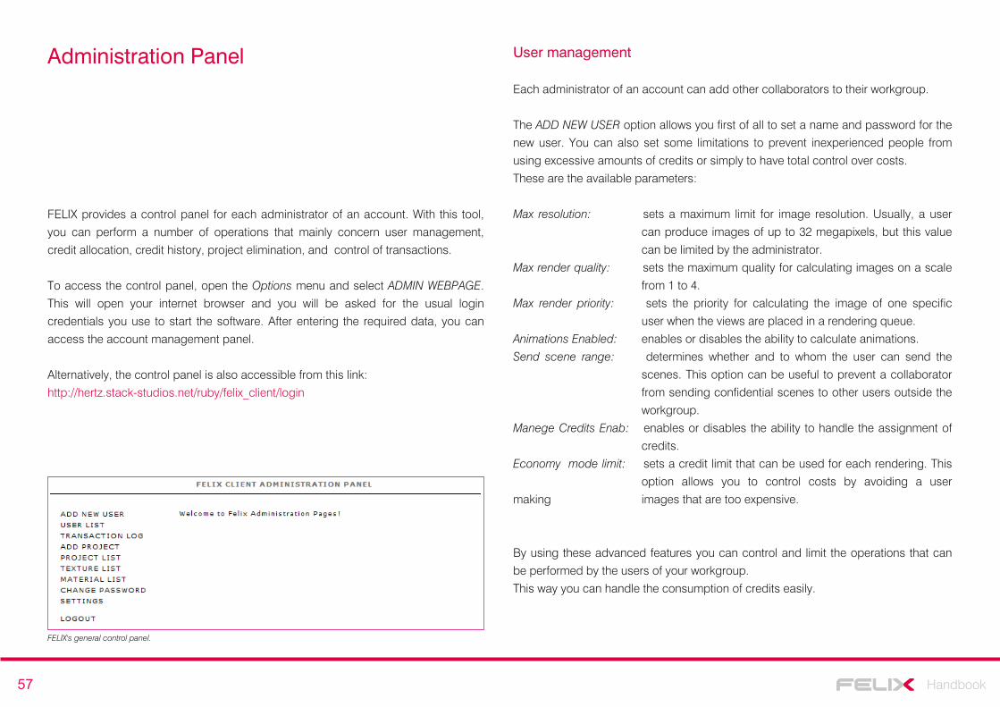
57 Handbook
Administration Panel
FELIX provides a control panel for each administrator of an account. With this tool,
you can perform a number of operations that mainly concern user management,
credit allocation, credit history, project elimination, and control of transactions.
To access the control panel, open the Options menu and select ADMIN WEBPAGE.
This will open your internet browser and you will be asked for the usual login
credentials you use to start the software. After entering the required data, you can
access the account management panel.
Alternatively, the control panel is also accessible from this link:
http://hertz.stack-studios.net/ruby/felix_client/login
Each administrator of an account can add other collaborators to their workgroup.
The ADD NEW USER option allows you first of all to set a name and password for the
new user. You can also set some limitations to prevent inexperienced people from
using excessive amounts of credits or simply to have total control over costs.
These are the available parameters:
Max resolution: sets a maximum limit for image resolution. Usually, a user
can produce images of up to 32 megapixels, but this value
can be limited by the administrator.
Max render quality: sets the maximum quality for calculating images on a scale
from 1 to 4.
Max render priority: sets the priority for calculating the image of one specific
user when the views are placed in a rendering queue.
Animations Enabled: enables or disables the ability to calculate animations.
Send scene range: determines whether and to whom the user can send the
scenes. This option can be useful to prevent a collaborator
from sending confidential scenes to other users outside the
workgroup.
Manege Credits Enab: enables or disables the ability to handle the assignment of
credits.
Economy mode limit: sets a credit limit that can be used for each rendering. This
option allows you to control costs by avoiding a user
making images that are too expensive.
By using these advanced features you can control and limit the operations that can
be performed by the users of your workgroup.
This way you can handle the consumption of credits easily.
User management
FELIX's general control panel.

58 Handbook
The USER LIST option provides a list of all users who are responsible for the same
account. For each of these, a residual credit count is provided. The administrator
can perform several tasks using the commands listed under the Actions field:
Change Credit: allows you to add, subtract, block, or set a total value for the user's
credits.
Setting: refers to the parameters available when creating the new user.
Send password: sends an email to the user with the FELIX login password.
Delete: deletes the user.
ADD PROJECT allows you to create a new project directly from the general control
panel. The project will then automatically appear in the internal list of the software.
For each project, you can select an administrator and set a limit to the number of
credits that can be used on it.
The PROJECT LIST option allows you to filter projects by name, user, or creation
date. It displays, for each project, all imported scenes and all calculated images. For
each of these, the resolution, date, calculation time and cost are also shown.
Other options provide complete lists of textures and materials made by various
users. With the SETTING option you can also change the administrator name and
the reference e-mail address.
All of these advanced tools allow for a detailed management of the account and its
users, while also guaranteeing in-depth project management with a constant budget
check.