HALFEN CURTAIN WALL SUPPORT SYSTEMS -...
36
HCW 13-E HALFEN CURTAIN WALL SUPPORT SYSTEMS FAÇADE
Transcript of HALFEN CURTAIN WALL SUPPORT SYSTEMS -...

HCW 13-EHALFEN CURTAIN WALL SUPPORT SYSTEMS
FAÇADE

2
DEMU Sockets/Inserts
HMS -Brick-tie Channels
HTU Cast-in Channels
HTA Cast-in Channels
HGB Balustrade Fixings
HTA-CSCurved Solutions Channels
HZA - DYNAGRIP
Cast-in Channels
HALFEN Framing System/Accessories
HALFEN Framing Channels and HALFEN Bolts
FIXING SYSTEMS, FRAMING SYSTEMS AND ACCESSORIES
HBS-05 Screw Connections
HBTRebend Connections
HDB Shear Rails
HIT ISO-Element
HBBbi-Trapez-Box ®
HSC Stud Connector
HCC Column Shoe
HTT/HTF Impact Sound Insulation
Elements
REINFORCEMENT SYSTEMS
DETANRod System
DEHA Lifting Anchorsand Socket
Anchor System
DEHA HD-Socket Lifting Anchor
System
FPA Precast
Panel Anchors
HK4 Brickwork
Support System
HK4SUKSub-structure
MVA Sleeve Sandwich Panel Anchors
and Flat Anchors
UMAGrout-in Anchors
BA Body Anchor
LIFTING SYSTEMS, CONCRETE PRE-CAST SYSTEMS, NATURAL STONE SYSTEMS, BRICKWORK SUPPORT SYSTEMS, ROD SYSTEMS
Connection Solutions.The HALFEN Product range.
Footbridge Simone de Beauvoir, Paris
MBT Reinforcing coupler
FRIMEDALifting Anchor
System
© 2013 HALFEN · HCW 13-E · www.halfen.com

3
HALFEN Cast-in channels:
System advantages and installation methods 5
Installation examples 8
Typical details of curtain wall connections 10
Advantages of the HALFEN Cast-in channel system 12
Selection of HALFEN Cast-in channels
• Product range 14
• Calculation examples 16
Calculation software for HTA-CE Cast-in channels 18
Load data for HALFEN Cast-in channels
• HZA DYNAGRIP Hot-rolled serrated channels 20
• HTA-R / HZA-R Channels for thin slabs 22
• HCW 52/34 Channels for thin slabs 24
• HTU Channels for self-tapping screws 26
HALFEN Curtain wall brackets
• HCW-ED / -EW Connections to edge of slab 27
• HCW-B1 / -B2 Connections to top of slab 30
DETAN Tension rod system for bracing and support 32
Contact information 35
HALFEN CURTAIN WALL SUPPORT SYSTEMS
Contents
Page
Modern structures often demand high performance façades that can be reliably installed in a minimum time period to meet tight construction schedules.
Curtain wall façades are one of the façade systems increasingly selected
HALFEN Cur ta in wal l sys tem
by architects and their clients. Curtain walls can be constructed in a variety of materials - glass, metal or stone - sup-ported by a steel or aluminium frame. The frame can be either pre- assembled in a factory as a fi nished element or assembled on-site immediately prior to installation to the main structure.
To maximise effi ciency and reliability in installation, HALFEN Cast-in channels and HALFEN T-bolts are often the pre-ferred method selected for connecting façade elements to a building’s super-structure.
© 2013 HALFEN · HCW 13-E · www.halfen.com

4
HALFEN CURTAIN WALL SUPPORT SYSTEMS
HALFEN - Wor ld Leader in Cur ta in Wal l Connect ions
Mercedes Benz Centre, Munich
Shor t pro ject over v iew
Petronas Towers, Kuala LumpurLittle Britain, London
Jin-Mao, Shanghai
Messeturm, Frankfurt
Peoplebuilding Hemel, UK
Sage Music Centre, Gateshead, UK
© 2013 HALFEN · HCW 13-E · www.halfen.com

5
Main features of all HALFEN Channel systems:• optimal reliability• wide range of T-bolts• wide range of channel profi les• high quality materials and fi nishes• simple and quick installation and adjustment• independently tested and approved load capacities• no power tools required no vibration, dust or excessive
noise
HALFEN CURTAIN WALL SUPPORT SYSTEMS
The HALFEN Cas t - in Channel Sys tem
Main features
The HALFEN Channel systems include channels that are cast into the concreteframe of the super-structure; T-bolts and special brackets are used to connect the façade elements. The HALFEN Channel system is a cost eff ective and reliable method for installing façade systems.
Façade f ix ing with HALFEN Cas t - in channels
© 2013 HALFEN · HCW 13-E · www.halfen.com

6
HALFEN CURTAIN WALL SUPPORT SYSTEMS
Ins ta l la t ion Methods for HALFEN Cas t - in Channels
HALFEN Cast-in channels can be installed using several methods. The selected method depends on the type of structure and the type of formwork used. A typical installation sequence in a wood based formwork is shown below.
HALFEN Cast-in channels installed in the top of a concrete slab; in this case an auxiliary construction is required to secure the HALFEN Cast-in channel in position. Two possible methods for installation are illustrated below.
... other fi ller material from the channel.
Insert a T-bolt into the channel and rotate ninety degrees clockwise.
A combination of HALFEN Cast-in channels and slotted brackets provide a 2 or 3-D adjustable connection for curtain wall components.
HALFEN Cast-in channels for installation to the top of a slabsecured to wood battens nailed to the side formwork.
HALFEN Cast-in channels, for top of a slab installation secured to the top of the reinforcement using HALFEN ChanClips (patent pending).
Nail through holes provided in the HTA-CE Channel
Wooden batten nailed or screwed to edge formwork
HALFEN HTA-CE Cast-in channel nailed or wired to wood batten
Edge formwork
HALFEN Cast-in channel type HTA-CE
HALFEN HTA-CE Cast-in channel
When the concrete has cured, strike the formwork and remove the foam strip or ...
Nail the channels in the correct position to the formwork and pour the concrete.
HALFEN ChanClip
HALFEN HTA-CE Cast-in channel
Rebar to support ChanClip
HALFEN ChanClip
HALFEN ChanClip
Attach the component. Adjust and tighten the nut. Use a torque wrench to fi nally secure all components to the channel.
Typica l ins ta l la t ion
Rebar to support ChanClip
© 2013 HALFEN · HCW 13-E · www.halfen.com

7
HALFEN CURTAIN WALL SUPPORT SYSTEMS
HALFEN Qual i t y
Qual i t y
Quality is the outstanding feature of our products. HALFEN materials and products are subjected to the most stringent quality control procedures. A quality inspection by the German Lloyd Certifi cation GmbH has verifi ed that our quality management system meets the requirements of the DIN EN ISO 9001:2008 standard.
Quality
Why chose HALFEN T-bolts and channels?
Product safety; gives the customer what they expect.
Certifi cate-no. QS-281 HH
Spectral analysisDuctile stress test
• guaranteed ductility; no sudden material failure• tolerance coordinated channels and bolts • purpose designed T-bolt head shape guarantees optimal fi t
for the bolt• meticulous multi-process forge method carefully fashions
the material to the correct head shape
Destructive testingProducts are randomly selected and are subjected to failure tests to ensure all HALFEN products exceed minimal proper-ties and requirements.
Non-destructive testing Materials are checked using spectral analysis to ensure correct raw materials are used in the production of HALFEN products.
The HALFEN production plant in Lan-genfeld/Germany is certifi ed according to DIN EN ISO 9001. This includes continuous monitoring of all processes and maintenance of all machines. All procedures are according to HALFEN DIN EN ISO 9001 QS quality system. The HALFEN production plant is certi-fi ed for welding according to internati-onal standard DIN EN ISO 3834-2 and according to German DIN 18800-7.
All incoming materials are monitored to ensure quality: DIN EN 10204 Cer-tifi cates are required from all sup-pliers. All materials properties are mo-nitored by HALFEN Quality Manage-ment, including chemical, mechanical properties, and dimensions. To ensure continuous quality, all products are randomly tested during production; this includes tensile failure tests and zinc coating testing to guarantee cor-rosion resistance.
© 2013 HALFEN · HCW 13-E · www.halfen.com

8
HALFEN CURTAIN WALL SUPPORT SYSTEMS
Curtain wall connections installed to the top of fl oor slabs using HALFEN HTA-CE Cast-in channels.
Curtain wall connection on the top of fl oor slabs using serrated HALFEN HZA Cast-in channels. The serration in the channel prevent windload slippage. One or two channels can be used per bracket.
Two channels used for high loads.
Ins ta l la t ion Examples
Curtain wall connections to the top of fl oor slab usingHALFEN HTA-CE Cast-in channel.
© 2013 HALFEN · HCW 13-E · www.halfen.com

9
HALFEN CURTAIN WALL SUPPORT SYSTEMS
Curtain wall connection to the edge of a post tensioned slab and thin slab using HALFEN Cast-in channels.
Sunscreen\maintenance gallery connected to top of a beam using HALFEN Cast-in channels.
Window connections to precast panels.
Ins ta l la t ion Examples
© 2013 HALFEN · HCW 13-E · www.halfen.com

10
Typica l Cur ta in Wal l Connect ions and Appl icat ions
Typical detail; connection to top of slab Typical detail; connection to metal rib-deck slab
Base connection for curtain wall or shop front. Sliding head connection for curtain wall.
Façade connections vary according to their purpose and the type of structure. Four typical examples are shown below.Please contact your local HALFEN representative for more assistance.
Mullion
Curtain wall bracket
HALFEN Cast-in channel andT-head bolt
HALFEN T-head bolts
Two way adjustment for securing connection to the main structure.Two T-head bolts may be required to prevent the mullion rotating.
Final fl oor surface
Slotted and serrated bracket
HALFEN Cast-in channel. Length and size of channel to suit load requirements.Including HALFEN T-head bolt and nut.
Concrete slab/beam/ metal deck
Connection to structure; two-way adjustable, allows vertical movement in the façade for expansion, contraction and defl ection.
Steel beam
HALFEN Channel welded or bolted to beam in pairs. Length and size of channel to suit load requirements. Including HALFEN T-head bolt and nut.
Slotted and serratedbracket
Minimal edgedistance
Metal rib-deck
HALFEN Cast-inchannelHTA-CE or HTA-R
Edge trim orHALFEN PourStop
HALFEN Cast-inchannelHTA-CE or HTA-R
HALFEN CURTAIN WALL SUPPORT SYSTEMS
Appl icat ion examples
© 2013 HALFEN · HCW 13-E · www.halfen.com

11
Typica l Cur ta in Wal l Connect ions and Appl icat ions
Four typical examples illustrating types of connections used with curtain wall façades. Please contact your local HALFEN representative if you require more information.
Typical detail; handrail stanchion anchorage Typical detail; single or strip window element anchorage
Steel beam to concrete connection using HALFEN HZA Cast-in channel and beam clamps.
Typical detail; anchoring of sunscreen / glazing using HALFEN Cast-in channels and DETAN Tension rod system (see page 32).
Min
. ed
ge d
ist.
Min
. ed
ge d
ist.
HALFEN Cast-in channel
Handrail stanchion
Glass infi ll panel
Opaque façade panel
HALFEN T-head boltand nut
Floor slab or staircase element
Shim to align
Top detail
HALFEN T-head boltand nut
Window frame
Cill detail
HALFEN Cast-inchannel inprecast panelor in-situ concrete
Top bracket
HALFEN Cast-inchannel inprecast panelor in-situ concrete
HALFEN T-head boltand nut
Guide-rail for windowmaintenance unit
HALFEN HZA Cast-in channel, serrated
Section throughsunscreen / glazing detail
DETAN Tension rod fi xed to screen support and HALFEN Cast-in channels
HALFEN HZACast-in channelswith optionalwelded spacers
Elevation of lowersunscreen fi xing detail
Curtain walling bolted to structure using HALFEN Cast-in channels
Sunscreen; slotted bracket and fi xingfor fourHALFEN T-head bolts
elev
atio
n
HALFEN CURTAIN WALL SUPPORT SYSTEMS
Appl icat ion examples
© 2013 HALFEN · HCW 13-E · www.halfen.com

12
A torque wrench is the only tool required for installation.
Advantages of the HALFEN Channel Sys tem
• only simple tools needed for installation• easy and quick to install• easily adjustable connections• no electrical power required during installation• fully tested components with verifi ed load capacities• visual check suffi cient to confi rm correct installation• no damage to the reinforcement• no subsequent welding required• no extra brackets required for connections• high quality materials and quality galvanization protect
components from corrosion• no dowels are used: no drilling, therefore no noise,
no vibration, no dust• no additional costs; no electricity required, no wear and
tear of tools
HALFEN CURTAIN WALL SUPPORT SYSTEMS
HALFEN Channels
© 2013 HALFEN · HCW 13-E · www.halfen.com

13
Welding is slow, is a fi re risk, and needs to be closely monitored to ensure quality.
Welding requires moving heavy equipment and also requires a costly energy supply.
Advantages of HALFEN Cas t - in Channels Compared to Dr i l led and Welded Connect ions
Vibration can also cause permanent health damage.
• power tools cause vibration, noise and dust work-safety hazards and reduced available installation time
• additional drilling required if adjustment is needed after ini-tial installation slower installation, drilling
• on-site check for installation quality is unreliable (depth of hole, hole diameter, critical torque) higher risk
• drilling costs time and bolt installation requires further tests to verify quality slower installation
• heavy electrical equipment, trailing cables and electricity safety hazards
• drilling and the expansion forces from installed bolts may damage concrete and reinforcement higher risk and po-tential high repair costs
• sparks from welding can start fi res and damage glass and aluminium façades high risk and high cost
• quality welding is diffi cult to achieve and verify on site increased uncertainty
• welding takes time and requires testing to verify quality slow installation and increased uncertainty
• heavy electrical equipment, trailing wires and electricity safety hazards
• subsequent adjustment requires welds to be broken and re-welded slow installation
• cast-in plates are designed per project and require testing to verify performance
• requires post-welding corrosion protection poor corro-sion protection, time consuming checking for damage to façade from dripping paint; hazardous to health
HALFEN CURTAIN WALL SUPPORT SYSTEMS
WeldingDr i l led bol ts
© 2013 HALFEN · HCW 13-E · www.halfen.com

14
52,5HZA 53/34
HZS 53/34M16 / M20
3414
0
64HZA 64/44
HZS 64/44M20 / M24
44
140
22,5 26
52.5
33.5
61
22.5
≥12
5
HCW 52/34
HS 50/30, M16, M20grade 8.8
Load condi t ions and requi red HALFEN Channels
Se lect ing the Correct HALFEN Cas t - in Channel for Each Load Condi t ion
Thin slab conditions with high shear loads and close edge distancesHALFEN (high load) Cast-in channel
Thin slab conditions with high tension loadsHALFEN Cast-in channels with rebar anchors
Normal slab conditionsHALFEN Cast-in channels with bolt anchors
Serrated channels and bolts
High load channel and bolts
Serrated channels with rebar anchors and bolts
HALFEN CURTAIN WALL SUPPORT SYSTEMS
© 2013 HALFEN · HCW 13-E · www.halfen.com

15
HTA-CE 40/22 HTA-CE 50/30 HTA-CE 52/3452,2
26,5
54,5
222218
33,5
66,2
124,
2
140
60,9
3023
42
39,5 49HTA-CE 55/42
HSR 50/30, M20HS 50/30, M12, M16, M20HS, HSR 40/22
M 12, M16
119
54
33
22
60
49
30
22
51
40
25
18
6817
38
18
HS 38/17M12, M16
HS 50/30M12, M16, M20
HS 40/22M12, M16
HTA-CE 38/17 HTA-CE 40/25 HTA-CE 49/30 HTA-CE 54/33
23
39,5
18
150
30
49
22,5
220
52,5
33,5
330
22,5
HTA-R 50/30HTA -R 40/22
HS 50/30M12, M16, M20
HTA-R 52/34
HS 40/22M12, M16
17
38
18
150
40
25
18
150
50
30
22
220
54
33
22
330
HS 38/17M12, M16
HS 50/30M12, M16, M20
HS 40/22M12, M16
HTA-R 54/33HTA-R 49/30HTA-R 40/25HTA-R 38/17
Select ing the Idea l HALFEN Cas t - in Channel for each Load Condi t ion
Standard hot-rolled channels and bolts Standard cold-rolled channels and bolts
Standard hot-rolled channels with rebar anchors and bolts Standard cold-rolled channels with rebar anchors and bolts
HALFEN CURTAIN WALL SUPPORT SYSTEMS
Load condi t ions and requi red HALFEN Cas t - in channels
© 2013 HALFEN · HCW 13-E · www.halfen.com

16
OK OK OK
>>>
>>>
OK OK OK OK
Calcu lat ion Example - How to Se lect the Right Channel
Example 1 - HZA
SELECTED BOLTS:
2 pieces HZS 38/23 M12×60 gv 8.8 (see page 21)
HALFEN CURTAIN WALL SUPPORT SYSTEMS
Given:
Working loads on the curtain wall bracket:- working dead load (gravity) Fg = 6.00 kN- working wind load Fw = 12.00 kN
The calculation example uses load and resistance factor design,applying partial safety factors F on the load side (action).
for dead loads: F = 1.35 (acc. to German standard DIN 1045-1 )for wind loads: F = 1.50 (acc. to German standard DIN 1045-1 ) - design dead load Fgd = F × Fg = 1.35 × 6.0 kN = 8.1 kN- design wind load Fwd = F × Fw = 1.5 × 12.0 kN = 18.00 kN
Design forces, acting on the channel:
NEd ≙ BVd = (Fgd × 70 + Fwd × 30) / 130 = (8.1 × 70 + 18.0 × 30) / 130 = 8.51 kN Vy,Ed ≙ BHd = Fwd = 18.0 kN
= arctan (8.51 / 18.0) = 25.3° > 15°
N*Ed =
= = 19.91 kN
≙ 2 × 9.96 kN
SELECTED CHANNEL:
HZA 38/23 - 350 - 3 anchors with 2 bolts at 150 mm centres (see page 20)
required ar = 150 mm (see page 20)
according to expert report
NEd = 8.51 kN = 2 × 4.26 kNResultant N*Ed
VyEd = 18.0 kN = 2 × 9.0 kN
Partial safety factors F may vary according to local design standards.
VyEd = 9.0NEd = 4.26FSEd = 9.96
VyRd = 27.2 NRd = 27.2 FSRd = 27.2
VyRd = 2 × 9.8 NRd = 2 × 14.0 N*Rd = 2 × 14.0
VyEd = 2 × 9.0NEd = 2 × 4.26N*Ed = 2 × 9.96
© 2013 HALFEN · HCW 13-E · www.halfen.com

17
c=
15
0
OK OK OK
>>>
OK OK OK OK
>>>>
Calcu lat ion Example - How to Se lect the Right Channel
Example 2 - HZA -R
Given:
Working loads on the curtain wall bracket- working dead load (gravity) Fg = 2.00 kN- working wind load Fw = 10.00 kN
The calculation example uses load and resistance factor design,applying partial safety factors F on the load side (action).
for dead loads: F = 1.35 (acc. to German standard DIN 1045-1 )for wind loads: F = 1.50 (acc. to German standard DIN 1045-1 ) - design dead load Fgd = F × Fg = 1.35 × 2.0 kN = 2.7 kN- design wind load Fwd = F × Fw = 1.5 × 10.0 kN = 15.0 kN
Design forces, acting on the channel:
NEd ≙ Zd = Fwd + Fgd × (100 / 35) = 15.0 + 2.7 × (100 / 35) = 22.7 kNVy,Ed ≙ Qd = Fgd = 2.7 kN
N*Ed =
= kN
≙ 2 × 11.43 kN
SELECTED CHANNEL:
HZA-R 38/23 - 350 - 3 anchors with 2 bolts at 150 mm centres (see page 22)
actual ar = 60 mm (see page 22)
SELECTED BOLTS:
2 pieces HS 38/17 M12×60 gv 4.6 (see page 23)
Partial safety factors F may vary according to local design standards.
HALFEN CURTAIN WALL SUPPORT SYSTEMS
actual c = 150 required c ≥ 150 (see page 22)
Vy,Rd = 2 × 3.7 NRd = 2 × 14.0 N*Rd = 2 × 14.0
VyEd = 2 × 1.35NEd = 2 × 11.35N*Ed = 2 × 11.43
Vy,Ed = 1.35NEd = 11.35FSEd = 11.35
Vy,Rd = 13.0 NRd = 13.0 FSRd = 13.0
© 2013 HALFEN · HCW 13-E · www.halfen.com

18
HALFEN CURTAIN WALL SUPPORT SYSTEMS
Verifi cation method
9. Verify concrete failure for com-bined loading, (combination of 6. and 7. as well as combina-tion of 6. and 8.)
8. Verify concrete edge failure (loading in shear) consideringa possible structual edge reinforcement
7. Verify pry-out failure (loading in shear)
6. Verify concrete cone failure (tension loading)
5. Verify anchor pull-out failure (tension loading)
4. Verify the connection between anchor and channel (tension loading)
3. Calculate the anchor loads resulting from tensile loads and shear loads according to the load infl uence model (unfavourable anchor and load position)
2. Verify local load application (channel lips) for tension, shear and combined loading
1. Select channel
If verifi cation is negative, determine required additional reinforcement
If last verifi cation is negative, determine required additional reinforcement
HALFEN Software
Note: A free, simple to use calculation software to simplify planning can be downloaded at www.halfen.de
Engineering services and technical support for your individual projects.Contact information can be found on page 35 of this catalogue.
Technical supportThe following information is necessary to verify an anchor channel:
• type and material of HALFEN Cast-in channel
• length of the HALFEN Cast-in channel with number of anchors and spacing
• position of the HALFEN Cast-in channel in the concrete defi ned by its distance from the lower, the upper, the left and the right edge of the component
• thickness of the concrete component
• concrete strength class
• condition of the concrete; cracked or verifi ed as non-cracked
• with a dense reinforcement in the vicinity of the anchor channel
• HALFEN T-head bolt thread size
• bolt arrangement
• tensile load and shear load of each bolt
HALFEN Calcu lat ion Sof tware HTA -CE
Note:
© 2013 HALFEN · HCW 13-E · www.halfen.com

19
HALFEN CURTAIN WALL SUPPORT SYSTEMS
HALFEN Software HTA-CEHALFEN Software
Although HALFEN Cast-in channels could previously be selected from tables according to their load bearing capacity, the ETA requires a wider range of veri-fi cations for cast-in channels in combi-nation with the selected concrete. These verifi cations are processed by the user-friendly HALFEN software; in just a few seconds the user has a list of suitable HALFEN Cast-in channels for the relevant load situation.
Boundary conditions
The calculation takes into account all necessary boundary conditions, typical examples being:
• cracked or non-cracked concrete
• the concrete components geometry, in particular the distances of the channel to the component edge
• various reinforcement layouts
• consideration of several dimensions or characteristic loads
• loads positioning with a defi nable adjustment range, and the option of moving the defi ned bolt layout along the complete channel length
• verifi cation of the required HALFEN T-head bolts and if required also for stand-off installations
• engineering consideration of fatigue loads and fi re infl uence
The HALFEN Cast-in channel calculation program is based on ETA-09/0339 (European Technical Approval) and CEN/TS 1992-4 (Design standards of anchorages for use in concrete); the program provides the user with a convenient and very powerful calculation tool.
Screenshot 2: Input GUI (Graphic User Interface), HALFEN Software HTA-CE 2.10
Screenshot 1: The HALFEN HTA-CE 2.10 Software start screen
HALFEN Calcu lat ion Sof tware HTA -CE
Screenshot 3: Interactive 3D-display
Screenshot 4: Results list
All software can be found under: www.halfen.de → service → software/CAD
InputThe geometry and loads are entered interactively. The entries are displayed immediately in a 3D graphic. The entries can also be manipulated directly in the graphic. Click on the load, the measurement or the component line you want to change to make the required modifi cation.
ResultsAfter calculation the software output provides either the results for a prese-lected profi le, or – in the case of auto-matic selection – a list of all suitable profi les. Profi les and T-bolts with incomplete verifi cations are high-lighted in red.
Visual controlAll verifi cations for the current channel profi le are listed in a tree structure. Green checkmarks indicate successful verifi cations. Red checkmarks indicateproblem areas.
Print-outsPrint-outs are available in a brief ver-sion and in a verifi able long version. The long version includes a 2D graphic of the geometry and load, all decisive verifi cations and a diagram of necessary reinforcement.
© 2013 HALFEN · HCW 13-E · www.halfen.com

20
HALFEN Channel type HZA 29/20 HZA 38/23 HZA 53/34 HZA 64/44
250 mm2 anchors
350 mm3 anchors
350 mm3 anchors
350 mm3 anchors
350 mm3 anchors
Concrete compression strength ≥ C20/25
fck,cyl. = 20 N/mm²fck,cube = 25 N/mm²
NRd [kN] 2 × 8.4 2 × 11.2 2 × 14.0 2 × 30.8 (26.6 ) 2 × 37.8
VyRd [kN] 2 × 8.4 2 × 8.4 2 × 9.8 2 × 15.4 2 × 18.9
VxRd [kN] 2 × 7.6 2 × 9.0 2 × 12.0 2 × 22.0 2 × 27.0
N*Rd [kN] 2 × 8.4 2 × 11.2 2 × 14.0 2 × 30.8 (26.6 ) 2 × 37.8
V*Rd [kN] 2 × 8.4 2 × 8.4 2 × 9.8 2 × 15.4 2 × 18.9
ΔNRd [kN] 2 × 2.0 2 × 2.0 2 × 3.0 (2 × 2.4 ) 2 × 12.0 (10 ) 2 × 15.0 (11 )
Material:hot-dip galvanized
channel: W1.0044anchor: W1.0213 W1.0214 W1.1122
channel: W1.0044anchor: W1.0038
channel: W1.0044anchor: W1.0038
Material:stainless steel not available channel: W1.4571
anchor: W1.4571channel: W1.4571anchor: W1.0038
channel: W1.4571anchor: W1.0038
Notes: Other channel sizes are available in 150 - 6070 mm lengths. Please see the Technical Product Information HALFEN Cast-in channels. load side ΔNEd calculated with partial safety factor 1.0 only values for stainless steel
F F
c 100
250
≥ c 150
350
F F
≥ c 150
350
F F
≥ c 150
350
F F
≥c 150
350
F F
≥
44
140
26
,,
,
, ,
,
,
3414
022,5
HALFEN CURTAIN WALL SUPPORT SYSTEMS
Hot - ro l led Ser rated Channels HZA DYNAGRIP
Structural analysis
1 Shear Material Resistance Vy,Rd Vy,Ed1 Tension Material Resistance NR,d NEd2 Longitudinal Shear Material Resistance Vx,Rd Vx,Ed3 Resultant Shear Material Resistance V*Rd res. VEd
V*Rd V*Ed (15° )
4 Resultant Tension Material Resistance N*Rd N*Ed (15° 150° )
5 Dynamic Material Resistance NRd NEd
FRdMaterial resistance
FEdFactored design load
Factored des ign load condi t ions
HALFEN Cas t - in channels HZA DYNAGRIP - mater ia l des ign res is tance va lues
533829 64
© 2013 HALFEN · HCW 13-E · www.halfen.com

21
HALFEN Channel type HZA 29/20 HZA 38/23 HZA 53/34 HZA 64/44
HALFEN T-head bolt type HZS 29/20 HZS 38/23 HZS 53/34 HZS 64/44
Material grade Steel 8.8
Stainless steel A4-70
Steel 8.8
Stainless steel A4-70
Steel 8.8
Stainless steel A4-70
Steel 8.8
Bolt diameter and length(other bolt sizes see Technical Product
Information HALFEN Cast-in channels)
M12 M16 M12 M16 M16 M20 M16 M20 M20 M24 M20 M24
40506080100
6080
40506080100
40506080100
60100
65100
60100
65100
80125
80150
80125
80150
NRd = VyRd = FSRd [kN]
27.2 33.0 27.2 50.5 33.0 51.5 50.5 79.0 51.5 54.3 79.0 113.7
Vx;Rd [kN] 11.2 16.8 16.8 16.8 26.6 26.6 30.8 30.8 37.8 37.8 37.8 37.8
ΔNRd [kN] 2.0 2.4 2.0 3.0 10.0 10.0 12.0 12.0 11.0 11.0 15.0 15.0
Requiredtorque [Nm] 80 120 80 120 200 350 200 350 350 450 350 450
Designbending moment
MRd [Nm]
Steel 61.2 — 61.2 155.4 — — 155.4 303.0 — — 303.0 524.0
A4-70 — 116.6 — — 116.6 227.2 — —- 227.2 218.7 — —
Finish Steel HALFEN special finish is approved as an equivalent to hot-dipped galvanization suitable for interior façade connections
Notes: Channel load capacity must not be exceeded load side ΔNEd calculated with partial safety factor 1.0 only
Minimum spacings and edge distances [mm], for all concrete grades ≥ C20/25
HALFEN Channel type ar aa ae af d
HZA 64/44 250 500 225 450 187 + nom.c
HZA 53/34 200 400 175 350 177 + nom.c
HZA 38/23 150 300 130 250 99 + nom.c
HZA 29/20 100 200 80 200 83 + nom.c
Notes:The minimum dimensions given in the table apply to reinforced concrete. For non-reinforced concrete increase dimensions by 30%. Determined by channel height, anchor length and required concrete cover (as stated in DIN 1045-1).
,
,
,
,
HALFEN CURTAIN WALL SUPPORT SYSTEMS
Hot - ro l led Ser rated Channels HZA DYNAGRIP and T-head Bol ts
Structural analysis
Shear Material Resistance Vy,Rd Vy,EdTension Material Resistance NRd NEdLongitudinal Shear Material Resistance Vx,Rd Vx,EdResultant Material Resistance FSRd FSEd = Dynamic Material Resistance NRd NEd
FRdMaterial resistance
FEdFactored design load
HALFEN T-head bol ts HZS - mater ia l des ign res is tance per bol t
© 2013 HALFEN · HCW 13-E · www.halfen.com
22
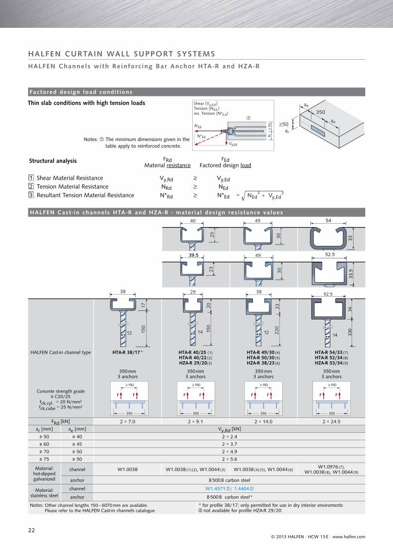
HALFEN Cast-in channel type HTA-R 38/17 * HTA-R 40/25 (1)HTA-R 40/22 (2)HZA-R 29/20(3)
HTA-R 49/30 (4)HTA-R 50/30 (5)HZA-R 38/23 (6)
HTA-R 54/33 (7)HTA-R 52/34 (8)HZA-R 53/34 (9)
350 mm3 anchors
350 mm3 anchors
350 mm3 anchors
350 mm3 anchors
Concrete strength grade≥ C20/25
fck,cyl. = 20 N/mm²fck,cube = 25 N/mm²
FRd [kN] 2 × 7.0 2 × 9.1 2 × 14.0 2 × 24.5
ar [mm] ae [mm] Vy,Rd [kN]
≥ 50 ≥ 40 2 × 2.4
≥ 60 ≥ 45 2 × 3.7
≥ 70 ≥ 50 2 × 4.9
≥ 75 ≥ 50 2 × 5.6
Material:hot-dipped galvanized
channel W1.0038 W1.0038 (1)(2), W1.0044 (3) W1.0038 (4)(5), W1.0044 (6)W1.0976 (7),
W1.0038 (8), W1.0044 (9)
anchor B 500 B carbon steel
Material:stainless steel
channel W1.4571 / 1.4404
anchor B 500 B carbon steel *
Notes: Other channel lengths 150 – 6070 mm are available. Please refer to the HALFEN Cast-in channels catalogue
* for profile 38/17; only permitted for use in dry interior enviromentsnot available for profile HZA-R 29/20
FF FF FF FF
150
17
38
12
40
25
29
2015
0
14
49
3030
49
38
2322
0
12
54
3333
.5
52.5
23
39.539,5
14
52.5
3433
0
HALFEN CURTAIN WALL SUPPORT SYSTEMS
Factored des ign load condi t ions
HALFEN Channels wi th Reinforc ing Bar Anchor HTA -R and HZA -R
Structural analysis
1 Shear Material Resistance Vy,Rd Vy,Ed2 Tension Material Resistance NRd NEd3 Resultant Tension Material Resistance N*Rd N*Ed =
Notes: The minimum dimensions given in the table apply to reinforced concrete.
Thin slab conditions with high tension loads
FRdMaterial resistance
FEdFactored design load
HALFEN Cas t - in channels HTA -R and HZA -R - mater ia l des ign res is tance va lues
© 2013 HALFEN · HCW 13-E · www.halfen.com

23
HALFEN Channel type HTA-R 38/17 HTA-R 40/25, HTA-R 40/22 HTA-R 49/30, HTA-R 50/30, HTA-R 54/33, HTA-R 52/34
HALFEN T-head bolt type HS 38/17 HS 40/22 HS 50/30
Material grade Steel 4.6Stainless steel A4-50
Steel 4.6Stainless steel A4-50 Steel 8.8 Steel 4.6
Stainless steel A4-50 Steel 8.8
Bolt diameter and lengthfor other bolt sizes see
Technical Product Information
HALFEN Cast-in channels
M12 M16 M12 M16 M12 M16 M12 M16 M20 M12 M16 M2040 50 60 80
40506080
4050
60 80
40506080
456080
6080
4050
60 80
40506080
55 65
75100
456080
6080100
6080100
NRd = Vy,Rd = FSRd [kN]
13.0 24.2 13.0 24.2 27.2 50.5 13.0 24.2 37.8 27.2 50.5 79.0
Vx,Rd [kN] — — — — — — — — — — — —
ΔNRd [kN] — — — — — — — — — — — —
Requiredtorque [Nm] 25 60 25 60 70 200 25 60 120 70 200 400
Designbending moment
M,Rd [Nm]
Steel 24.5 62.2 24.5 62.2 61.2 155.4 24.5 62.2 121.1 61.2 155.4 303.0
A4-50A4-70* *45.9 54.3 21.4 54.3 — — 21.4 54.3 106.0 — — —
Finish Steel HALFEN special finish is approved as equivalent to hot-dipped galvanization suitable for interior façade connections
HALFEN Channel type HZA-R 29/20 HZA-R 38/23 HZA-R 53/34
HALFEN T-head bolt type HS 28/15 HS 29/20 HS 38/17 HS 38/23 HZS 53/34
Material grade Steel 4.6 Steel 4.6 Stainless steelA4-50 Steel 4.6 Stainless steel
A4-70 Steel 8.8
Bolt diameter and length(see catalogue B-E for
other bolt sizes)
M10 M12 M12 M16 M12 M16 M16 M16 M20 M16 M2040506080
40506080
40506080
40506080
40 50 60 80
40506080
40506080
60100
65100
60100
65100
NRd = Vy,Rd = FS,Rd [kN]
9.0 13.0 13.0 24.2 13.0 24.2 24.2 33.0 51.5 50.5 79.0
Vx,Rd [kN] — — — — — — — — — — —
ΔNRd [kN] — — — — — — — — — — —
Requiredtorque [Nm] 15 25 25 60 25 60 60 60** 120** 60** 120**
Designbending moment
M,Rd [Nm]
Steel 14.0 24.5 24.5 62.2 — — 62.2 — — 155.4 303.0
A4-50A4-70 * — — — — *45.9 54.3 — 116.6 227.2 — —
Finish Steel HALFEN special finish is approved as an equivalent to hot-dipped galvanization suitable for interior façade connections
Notes: Channel load capacity must not be exceeded Stainless steel A4-70 Available in stainless steel material on request ** recommended values; only to be used for thin face applications
,
,
HALFEN CURTAIN WALL SUPPORT SYSTEMS
HALFEN Channels HTA -R, HZA -R and T-head Bol ts
Structural analysis
Shear Material Resistance Vy,Rd Vy,EdTension Material Resistance NRd NEdResultant Material Resistance FSRd FSEd =
HALFEN T-head bol ts HS - mater ia l des ign res is tance per bol t
F,RdMaterial resistance
F,EdFactored design load
© 2013 HALFEN · HCW 13-E · www.halfen.com

24
≥ 50
0≥
250
≥15
0
300≥150 ≥ 250
≥ 50
0
HALFEN CURTAIN WALL SUPPORT SYSTEMS
HALFEN High Load Channel HCW 52/34 for Cur ta in Wal l Connect ions
Typica l insta l la t ion Product descr ipt ion
Channel d imens ions and pos i t ion ingReinforcement requi rements
HALFEN T-bolt grade 8.8Type range see table page 25
Dimensions in mmSubject to change
9 b
ars
8 m
m d
iam
eter
at
100 m
m c
entr
es
3 bars8 mm diameter
at 100 mm centres
Curtain wall mullion
Bracket (example)
HALFEN Curtain wall channel HCW 52/34
Concrete slab
Product code: HCW 52/34
Material: W1.0038, hot-dipped galvanized
HALFEN T-head boltsstrength grade 8.8 (ordered separately)see table on page 25
Dimensions in mm
© 2013 HALFEN · HCW 13-E · www.halfen.com

25
Type selection HALFEN T-head bolts HS 50/30 grade 8.8
Thread size Material gradeDIN
Available lengths
L [mm]
Bolt load (pull,angled pull and shear)
FS allow. [kN]
Allowablebending moment
[Nm]
Recommended initial torque
[Nm]
The capacity of the T-bolts should be checked for allowable bending moment if slotted holes are used in the bracket to achieve tolerance transverse to the channel.
M 16 8.8 40, 60, 80, 100 36.1 111 180
M 20 8.8 45, 60, 80, 100 56.4 216 360
150
140
130
120
110
100
90
80
70
60
50
40
30
20
10
0
1 2 3 4 5 6 7
[kN]
36.4
γ 1=
4.1 2
Fres
HALFEN CURTAIN WALL SUPPORT SYSTEMS
HALFEN High Load Channel HCW 52/34 for Cur ta in Wal l Connect ions
Channel load data
Fastener in format ion
A series of three tests produced the following average ultimate loads:
The adjacent load deformation diagram can be used to determine allowable loads based on acceptable displacement and the required safety factor according to local building codes. The diagram is based on the following:• A concrete slab ≥ 125 mm thick and reinforced according to the
diagram on the previous page.• Concrete compression strength ≥ C 20/25 N/mm² (cylinder/cube)
with normal weight aggregate.• Load equally distributed to the channel via two HALFEN T-bolts
(ordered separately) spaced at ≥ 150 mm centres. See below for sizes and load capacities.
A typical calculation method is shown below. The factors used in the calculation example are just an example. Actual factors used on a project basis must be checked according to local or national building regulations. These calculations also make no allowance for load increase due to load eccentricities. These must be included according to the project design of the connection. Contact us if further information and help is required here.Calculation example: Assumed safety factor 3 applied to the ultimate test load.
HALFEN T-bolts type HS 50/30 8.8 grade, M16 and M20 suitable for the required load are recommended for use with HALFEN Cast-in channel HCW 52/34. The loads FS allow., see table below, are per bolt and based on applied safety factors of approximately 2.5 : 1; other factors may be applied accor-ding to appropriate regulations and project requirements.
Please note that fastener performance may be limited by channel capacity. The sizes shown result from salt spray tests with a special coating equivalent to hot-dipped galvanization. T-bolts in other sizes and materials are available if required. Please contact us for more details.
Actual safety factor to ultimate test load: 1 = (150 / 36.4) = 4.12
Displacement r [mm] in load direction FRes.
FRes. ultimate = 150 kN
Load deformation diagram
Load FRes.
1st crack appearingin the concrete
Ultimate test load: FResult. ultimate = 150.0 kN FV ultimate = 142.3 kN FN ultimate = 47.4 kN
Required working loads: FV work. = 35 kN, FN work. = 10 kN
Allowable load at 3:1 safety factor: FResult. allowable = 50.0 kN FV allowable = 47.4 kN FN allowable = 15.8 kN
Checking FV work. = 35 kN < 47.4 kN OKChecking FN work. = 10 kN < 15.8 kN OKChecking FResult. work. = = 36.4 kN < 50 kN OK
Displacement at working load < 1 mm (see diagram).
FV ultimate = 142.3 kN
FN ultimate = 47.4 kN
Fresult. ultimate = = 150.0 kN
© 2013 HALFEN · HCW 13-E · www.halfen.com

26
Channel type HTU 60/22/3 HTU 60/22/6
c [mm] e [mm] Design resistance FRd
225 450 4.6 kN / 450 mm 7.0 kN / 450 mm
75 150 7.0 kN / 150 mm 7.0 kN / 150 mm
225 450 3.5 kN / 225 mm 3.5 kN / 225 mm
75 150 3.5 kN / 75 mm 3.5 kN / 75 mm
Minimumconcrete
dimensions[mm]
aa 200 200 200 200
ar 100 100 100 100
ae 20 20 20 20
af 20 20 20 20
d 100 + cover 75 + cover 100 + cover 75 + cover
Notes: Self-tapping fixtures and the structure must be capable of supporting the loads. Fixtures should be positioned in the centre third of the rail width and no closer than 25 mm from the end of the channel. For pure tensile loads edge distances may be reduced to a minimum of 50 mm with a corresponding reduction in allowable load according to the formula: Reduced ar = (Reduced load x ar) / recommended load. Further design information is available in the HALFEN Cast-in channels, Technical Product Information.
Channel type HTU 40/25/2.5 - sv (IT) HTU 60/25/2.5 - sv (FR) HTU 80/25/3.0 - sv (FR)
Design resistance FRd 1.8 kN / 250 mm 1.8 kN / 250 mm 1.8 kN / 250 mm
Minimumconcrete
dimensions[mm]
aa 140 160 180
ar 70 80 90
ae 20 20 20
af 20 20 20
d 25 + cover 25 + cover 25.5 + cover
Notes: Suitable for pull-out, shear and resultant loads. Minimum required concrete strength C20/25 N/mm². Fixtures must be capable of supporting the loads, and be installed according to manufacturer´s recommendations.Concrete must be of sufficient depth to transfer loads from the channel and provide adequate cover.
25
39.5
39
27.2
2.5
59.5
25
47.2
59
2.5
80.5
25.5
67
79
3.0
d
af
ae
ar
araab
d
af
ae
ar
araab
60
100
22
3
75
60
3
63.5
60
100
22
6
7560
6
63.5
HALFEN Cas t - in Channels HTU for Se l f - tapping Screws
HALFEN HTU Cast-in channels provide an ideal method for connecting window frames, door frames, sheeting rails and metal cladding panels to concrete using self-tapping screws.They are easy to install and allow two dimensional adjustment for the connection.HTU self-anchoring channels are available pre-galvanized in lengths of six metres. For details of HTU Channels with welded anchors see below.
All HALFEN Cast-in channels type HTU 60/22 are available hot-dipped galvanized in 3 m lengths.HTU 60/22/3 is also available in A4 stainless steel. Anchors are spaced at 450 mm or 150 mm.
Maximum screwdepth 20 mm
Maximum screwdepth 20 mm
TypeAN
TypeD
TypeAN
TypeD
HALFEN CURTAIN WALL SUPPORT SYSTEMS
Cast - in channels HTU, se l f anchor ing
Cast - in channels HTU, welded anchors
© 2013 HALFEN · HCW 13-E · www.halfen.com

27
Bracket dimensions [mm]
HCW-ED Bracketsfor carrying dead loads and wind loads
HCW-EW Bracketsfor carrying wind loads only
serrated washers included serrated washers included
Size Bracket type A B C D E F G H J L M
small HCW-ED 1HCW-EW 1 108 70 114 10 57 64 25 51 36 40 57
medium HCW-ED 2HCW-EW 2 133 70 127 10 64 64 51 51 36 40 82
large HCW-ED 3HCW-EW 3 159 70 140 10 70 64 76 51 36 40 108
J
p
Fhd2
+−
Fvd2
HALFEN CURTAIN WALL SUPPORT SYSTEMS
Edge of S lab Brackets HCW-ED / -EW
HALFEN Edge of slab brackets are connected in pairs toeither side of the mullion and are available in two types:• HCW-ED brackets are designed to support both vertical
and horizontal loads.• HCW-EW brackets are designed to support horizontal wind
loads only.
The brackets connections are easy to adjust.T-head bolts M12 grade 8.8 connections are required for the mullion and cast-in channel. Pilot holes are also provided in the bracket if it is preferred to temporarily position the bra-cket prior to drilling the mullion for the main connection.
The brackets are manufactured from high strength alumini-um. Nylatron shims are available as low-friction shims for windload brackets.HCW-ED brackets are marked ‘R’ (right) and ‘L’ (left) with ‘UP’ at the top. Care should be taken to orientate the bra-ckets correctly to avoid overloading the connections.
bolt spacing
Appl icat ion example
© 2013 HALFEN · HCW 13-E · www.halfen.com

28
-25 2520-20 -15 15-10 10-5 0 5
-25 2520-20 -15 15-10 10-5 0 5
-25 2520-20 -15 15-10 10-5 0 5
Fvd2
Fvd2
Fhd2
Fhd2
+−+−
HALFEN CURTAIN WALL SUPPORT SYSTEMS
Des ign Loads us ing two Bracket Types HCW-ED
Load scheme for bolt connection betweenCurtain wall bracket / mullion
Design value of the horizontal applied load Fhd [kN]
Design value of the horizontal applied load Fhd [kN]
Design value of the horizontal applied load Fhd [kN]
Des
ign
valu
e of
the
ver
tical
app
lied
load
Fvd
[kN
]D
esig
n va
lue
of t
he v
ertic
al a
pplie
d lo
ad F
vd [
kN]
Des
ign
valu
e of
the
ver
tical
app
lied
load
Fvd
[kN
]
required connection boltsM12 grade 8.8
required connection boltsM12 grade 8.8
required connection boltsM12 grade 8.8
7.0
3.5
Permitted loadinteraction area
Interact ion d iagram type HCW-ED1 (smal l ) Calcu lat ion bas is
Interact ion d iagram type HCW-ED2 (medium)
Interact ion d iagram type HCW-ED3 ( large)
© 2013 HALFEN · HCW 13-E · www.halfen.com

29
Max. applied design load Fhd [kN]
Size Bracket code max. Fvd [kN] max. Fhd [kN]
small HCW-EW 1 0 ± 8.5
medium HCW-EW 2 0 ± 11.67
large HCW-EW 3 0 ± 13.96
HCW-EW brackets are for carrying windloads only
Bottom position fixing bolt (position 3)
Bracket
dead loadSi = (Fvd / 2) × si
wind loadSi = (Fhd / 2) × si
combined load 45°Si = (res. Fd / 2) × si
sx sy sz sx sy sz sx sy sz
HCW-ED 1 0.5 3.2 -1.0 -1.0 1.0 0.0 -0.3 3.0 -0.7
HCW-ED 2 0.5 3.6 -1.0 -0.5 1.0 0.0 0.0 3.3 -0.7
HCW-ED 3 0.5 4.0 -1.0 -0.4 1.0 0.0 0.1 3.5 -0.7
Top position fixing bolt (position 1)
HCW-ED 1 0.6 1.3 -1.0 -1.0 3.6 0.0 -0.3 3.4 -0.7
HCW-ED 2 0.6 1.6 -1.0 -0.5 3.1 0.0 0.0 3.4 -0.7
HCW-ED 3 0.6 1.9 -1.0 -0.4 2.9 0.0 0.1 3.4 -0.7
Sy
Sx
SzFvd2res.Fd
2
Fhd2
+−
HALFEN CURTAIN WALL SUPPORT SYSTEMS
Des ign Windloads for Brackets Type HCW-EW, Forces at the Bol t for HCW-ED
Calcu lat ion bas isDes ign windloads for type HCW-EW
To calculate the reaction force on the HALFEN T-head bolt in the connection HALFEN Curtain wall bracket to the HALFEN Cast-in channel, the design loads Fvd and Fhd at the connection between the curtain wall bracket and façade mullion can be multiplied with the factors sx, sy and sz. These factors depend on the bracket’s geometry, the load direction and the position of the bolt (see illustrations on the right). The multiplication factors to calculate the forces on the channel bolt can be found in the following table.
Load scheme for bolt connections between- Bracket / mullion- Bracket / HALFEN Channel
Bottom positionof fi xing bolt(position 3)
Given: slab thickness = 20 cm, width of mullion = 80 mm projection a = 80 mm (see page 28, calculation basis)
design dead load Fvd = + 3.5 kN design wind load (suction) Fhd = + 7.0 kN
Selected: HALFEN Bracket type HCW-ED 2 possible projection M = 82 ± 25 mm OK
interaction diagram type HCW-ED 2 (see page 28) proves that the given load is within the permitted load interaction area OK
Calculation of action at each HALFEN T-head bolt bottom bolt position (position 3) Sx = (3.5/2) × 0.5 + (7/2) × (-0.5) = - 0.88 kN Sy = (3.5/2) × 3.6 + (7/2) × 1.0 = + 9.80 kN Sz = (3.5/2) × (-1.0) + 0 = - 1.75 kN
resultant bolt load
(-0.88)2 + (9.80)2 + (-1.75)2 = 9.99 kN per bolt
Top positionof fi xing bolt(position 1)
Calcu lat ion example
top bolt position (position 1) Sx = (3.5/2) × 0.6 + (7/2) × (-0.5) = - 0.70 kN Sy = (3.5/2) × 1.6 + (7/2) × 3.1 = + 13.65 kN Sz = (3.5/2) × (-1.0) + 0 = - 1.75 kN
resultant bolt load per
bolt
SELECTED ANCHOR CHANNEL:
with VyRd = 2 × 5.6 kN > 2 × Sz = 2 × 1.75 OK (ar ≥ 7.5 cm)
N*Rd = 2 × 14.0 kN > 2 × res. Sd = 2 × 13.78 kN OK
SELECTED BOLTS:
HTA-R 50/30 - 350 - 3 anchors - fv (see page 22)
HS 50/30 - M12 × 60 gv 8.8
Forces act ing on the T -head bol ts at the channel
© 2013 HALFEN · HCW 13-E · www.halfen.com

30
Design load ranges
Load range[kN]
dead load Fvd[kN]
wind load Fhd [kN](wind-suction + compression)
4/12 4 ± 12
7/20 7 ± 20
Fvd , Fhd : allowable design loads with a partial safety factor F = 1.35 for dead loads and F = 1.5 for wind loads.
Type selection
Load range[kN]
a[mm]
Item nameHCW-B1 -...
L[mm]
W[mm]
HALFENChannel
Reccommded HALFEN Bolt
4/12
50 ...- 4/12-50 270 150 HTA-CE 40/22-2502 Anchors
HS 40/22M16×60
8.875 ...- 4/12-75 295 150
100 ... - 4/12-100 320 150
7/20
50 ...- 7/20 -50 270 175 HTA-CE 50/30-3003 Anchors
HS 50/30M16×60
8.875 ...- 7/20 -75 295 175
100 ...- 7/20 -100 320 200
Recommended HALFEN Cast-in channel exploiting full load capacityof the bracket
ds = 12 200
Dimensioning / Type se lect ion
Section
Plan
Required edge reinforcement ≥ ∅12 (B500B)
HALFEN CURTAIN WALL SUPPORT SYSTEMS
Top of S lab Brackets Type HCW-B1
Typical assembly
HALFEN Brackets HCW-B1 for top of slab are available in two load ranges and three sizes. The brackets are made of S355 grade quality galvanized steel. Three dimensional adjustability is ensured when used in combination with HALFEN HTA-CE Cast-in channels.The lateral connecting plates are connected to the façade posts using M8 screws (ordered separately).
Use HALFEN Bolts M16 grade 8.8 (order separately) to con-nect the base bracket to the HALFEN Cast-in channel. Depending on the façade type, the connection between the connecting plate and the base bracket can be designed to allow lateral expansion or as a fi xed point.
Typical Mullion in acurtain-wall façade
Concrete slab
HALFEN Cast-in channel
0,5 mm
© 2013 HALFEN · HCW 13-E · www.halfen.com

31
Section
Plan
Required edge reinforcement ≥ ∅12 (B500B)
Top of S lab Brackets Type HCW-B2
HTA-CEds = 12
200
Brackets for hor izonta l and ver t ica l loads
Element in thecurtain wall modular façade
Concrete slab
HALFEN Cast-in channel
Typical installation
HALFEN Brackets HCW-B2 are made of S355 grade quality galvanized steel. The vertical adjustability is ± 24 mm. Three dimensional adjustability is ensured when used in combinati-on with HALFEN HTA-CE Cast-in channels.The lateral connecting plates are connected to the façade posts using M12 screws (ordered separately).
Design value for the horizontal acting load Fhd [kN]
Des
ign
valu
e of
the
ver
tical
act
ing
load
Fvd
[kN
]
required bolt for connecting to channel
HS 50/30 M16×60 gv 8.8
Allowable load interaction area
Use HALFEN Bolts M16 grade 8.8 (order separately) to con-nect the base bracket to the HALFEN Cast-in channel.Depending on the façade type, the connection between the connecting plate and the base bracket can be designed to allow lateral expansion or as a fi xed point.
anchoranchor
HCW-B2
Dimensioning
HALFEN CURTAIN WALL SUPPORT SYSTEMS
© 2013 HALFEN · HCW 13-E · www.halfen.com

32
HALFEN CURTAIN WALL SUPPORT SYSTEMS
DETAN Tension rods are engineered to a high standard and aesthetically fi nished to give complete creative freedom in the de-sign of glass and metal façades. DETAN Tension rods are used for both bracing and support of most façade elements and other architectural features. The system components are outlined below. Further details are available in the DETAN catalogue.
DETAN Tens ion Rod Sys tems for Façade Brac ing and Suppor t
DETAN - The per fect sys tem for suppor t ing cur ta in wal l sys tems
© 2013 HALFEN · HCW 13-E · www.halfen.com

33
DETAN system load capacities, steel strength grade S355 (Ø ds 6-12), strength grade S460N (Ø ds 16-95) Hot dipped galvanized or mill finished
System - Ø ds [mm] 10 12 16 20 24 27 30 36 42 48 52 56 60 76 85 95
Load capacity NRd [kN] 21.3 30.94 70.5 110.2 158.6 206.7 252.3 267.5 504.4 662.9 791.0 913.5 1063 1750 2227 2823
The partial safety value for above table has been calculated with M1 = 1.1 and M2 = 1.25 acc. to ETA 05/0207If other partial safety values apply the load capacities have to be calculated accordingly.➄ NRd: Design load acc. type test report DETAN-5460 in accordance with ETA-Approval 05/0207
Available finishes and system lengths
Carbon steel systems Stainless steel systems
Rod diameter Available system length Rod diameter Available system length
6 mm 3 metres 6 mm 3 metres
8-12 mm 6 metres 8-30 mm 6 metres
16-60 mm 12 metres
64-95 mm 15 metres
lengths are approximate
f
Locking NutRod
Connection
plate to
structure
Fork Connector
Pin
Circlip
Coupler
with lug
System
length
L
System
length
L
Coupler
Seals (optional)
Anchor disc
HALFEN CURTAIN WALL SUPPORT SYSTEMS
DETAN Tens ion Rod Sys tems for Façade Brac ing and Suppor t
A typical installation can consist of some or all of the standard components as shown.Please note how the system length L is defi ned
DETAN Sys tem in carbon s tee l and s ta in less s tee l
System load capacities, in stainless steel A4, European Technical Approval ETA-11/0311
System diameter ds [mm] 6 8 10 12 16 20 24 27 30
Load capacity NRd [kN] ➄ 9.42 17.13 27.14 39.44 73.32 114.6 165.0 215.0 262.4
The partial safety value for above table has been calculated with M1 = 1.1 and M2 = 1.25 acc. to ETA 11/0311If other partial safety values apply the load capacities have to be calculated accordingly.➄ NRd: Design load acc. type test report DETAN-5460 in accordance with ETA-Approval 11/0311
© 2013 HALFEN · HCW 13-E · www.halfen.com

34
Anchor discs dimensions [mm]; Stainless steel A4, strength grade S235
System - Ø ds 6 8 10 12 16 20 24 27 30
Effective diameter Ø f 55 75 90 110 140 180 210 240 260
Anchor disc diameter Ø g 73 99 120 146 186 238 280 318 346
Anchor discs dimensions [mm]; Material specification: steel strength grade S355J2, hot dip galvanized
System - Ø ds 10 12 16 20 24 27 30 36 42 48 52 56 60 76 85 95
Effective diameter Ø f 90 110 140 180 210 240 260 310 360 420 450 490 520 702 777 832
Anchor disc diameter Ø g 120 146 186 238 280 318 346 412 480 558 600 652 692 960 1075 1150
Cross coupler dimensions [mm]; Material specification: Steel strength grade S355J2, hot-dip galvanized
System diameter ds 16 20 24 27 30 36Coupler length LKM 142 166 200 222 242 284
Coupler diameter dKM 32 39 46 52 57 70
Crossing rod Ø dsk 16 20 24 27 30 36
Dimensions [mm]; Material: Stainless steel A4 (1.4404 / 1.4571), strength grade S355
System - Ø ds 6 8 10 12 16 20 24 27 30
Coupler length LM 34 40 40 50 62 78 94 104 120
Coupler - Ø dM 12 15 20 22 28 35 42 47 53
Screw-in depth om 10.5 12.5 15.0 18.5 22.5 27.0 34.0 37.5 42.5
Screw-in adjustment oj 4.5 4.5 5.0 6.5 7.5 8.0 11.0 12.5 12.5
Suspension system size- Ø dsa - - - 6 6 8 8 10 10
Hole position km - - - 27.5 33.0 37.0 44.0 50.5 57.5
Dimensions [mm]; Material: Steel strength grade S355J2 Hot dip galvanized
System - Ø ds 10 12 16 20 24 27 30 36 42 48 52 56 60 76 85 95
Coupler length LM 40 50 62 78 94 104 120 140 158 180 195 210 245 328 370 450
Coupler - Ø dM 20 22 28 35 42 47 53 64 75 87 93 98 104 155 180 195
Screw-in depth om 15.0 18.5 22.5 27.0 34.0 37.5 42.5 51.0 55.0 62.5 70.5 77.5 85.0 115 130 155
Screw-in adjustment oj 5.0 6.5 7.5 8.0 11.0 12.5 12.5 14.0 15.0 17.5 20.0 22.5 25.0 39 45 60
Suspension system size- Ø dsa - 10 10 10 10 10 10 10 10 12 12 12 12 12 16 16
Spacing bolts. km - 28.0 31.0 44.5 48.0 50.5 57.5 72.0 86.5 98.5 111.5 124.5 137.0 140.0 150.0 157.5
Size hook spanner - - - - - - - - - - - - - 155/8 230/10 230/10
ds
LM
om
+ jo - jo
k M
ds
LM
k M
dsa
ds
LM
dM
min. 40°
Ø j
Øf
bØ
g
ds
dsk
dKMLKM
αm
in =60°-90°
HALFEN CURTAIN WALL SUPPORT SYSTEMS
DETAN Tens ion Rod Sys tems for Façade Brac ing and Suppor t
Anchor discs Anchor disc with 4 tension rods Maximum of 8 rod connections per disc Cross coupler
Couplersavailable with or without lug for suspension connection
DETAN Components in carbon s tee l and s ta in less s tee l
Cross coupler dimensions [mm]; Stainless steel A4, strength grade S235
System - Ø ds 16 20 24 27 30
Coupler length LKM 142 166 200 222 242
Coupler diameter - Ø dKM 32 39 46 52 57
Crossing rod Ø dsk 16 20 24 27 30
© 2013 HALFEN · HCW 13-E · www.halfen.com

CONTACT HALFEN WORLDWIDEHALFEN is represented by subs id iar ies in the fo l lowing 14 countr ies , p lease contact us :
Austria HALFEN Gesellschaft m.b.H.Leonard-Bernstein-Str. 101220 Wien
Phone: +43 - 1 - 259 6770 E-Mail: [email protected]: www.halfen.at
Fax: +43 - 1 - 259 - 6770 99
Belgium / Luxembourg HALFEN N.V.Borkelstraat 1312900 Schoten
Phone: +32 - 3 - 658 07 20E-Mail: [email protected]: www.halfen.be
Fax: +32 - 3 - 658 15 33
China HALFEN Construction Accessories Distribution Co.Ltd.Room 601 Tower D, Vantone CentreNo. A6 Chao Yang Men Wai StreetChaoyang District Beijing · P.R. China 100020
Phone: +86 - 10 5907 3200E-Mail: [email protected]: www.halfen.cn
Fax: +86 - 10 5907 3218
Czech Republic HALFEN-DEHA s.r.o.Business Center ŠafránkovaŠafránkova 1238/1155 00 Praha 5
Phone: +420 - 311 - 690 060E-Mail: [email protected]: www.halfen-deha.cz
Fax: +420 - 235 - 314 308
France HALFEN S.A.S.18, rue Goubet75019 Paris
Phone: +33 - 1 - 445231 00E-Mail: [email protected]: www.halfen.fr
Fax: +33 - 1 - 445231 52
Germany HALFEN Vertriebsgesellschaft mbHKatzbergstrasse 3 40764 Langenfeld
Phone: +49 - 2173 - 970 - 0E-Mail: [email protected]: www.halfen.de
Fax: +49 - 2173 - 970 225
Italy HALFEN S.r.l. Soc. UnipersonaleVia F.lli Bronzetti N° 2824124 Bergamo
Phone: +39 - 035 - 0760711E-Mail: [email protected]: www.halfen.it
Fax: +39 - 035 - 0760799
Netherlands HALFEN b.v.Oostermaat 37623 CS Borne
Phone: +31 - 742 - 6714 49E-Mail: [email protected]: www.halfen.nl
Fax: +31 - 742 6726 59
Norway HALFEN ASPostboks 20804095 Stavanger
Phone: +47 - 51 82 34 00E-Mail: [email protected]: www.halfen.no
Fax: +47 - 51 82 34 01
Poland HALFEN Sp. z o.o.Ul. Obornicka 28760-691 Poznan
Phone: +48 - 61 - 622 14 14E-Mail: [email protected]: www.halfen.pl
Fax: +48 - 61 - 622 14 15
Sweden Halfen ABBox 150435 23 Mölnlycke
Phone: +46 - 31 - 98 58 00E-Mail: [email protected]: www.halfen.se
Fax: +46 - 31 - 98 58 01
Switzerland HALFEN Swiss AGHertistrasse 25 8304 Wallisellen
Phone: +41 - 44 - 849 78 78E-Mail: [email protected]: www.halfen.ch
Fax: +41 - 44 - 849 78 79
United Kingdom /Ireland
HALFEN Ltd.Humphrys Road · Woodside EstateDunstable LU5 4TP
Phone: +44 - 1582 - 47 03 00E-Mail: [email protected]: www.halfen.co.uk
Fax: +44 - 1582 - 47 03 04
United States of America HALFEN USA Inc.8521 FM 1976P.O. Box 547Converse, TX 78109
Phone: +1 800.423.91 40E-Mail: [email protected]: www.halfenusa.com
Fax: +1 877.683.4910
For countries not listed HALFEN International
HALFEN International GmbHLiebigstr. 14 40764 Langenfeld / Germany
Phone: +49 - 2173 - 970 - 0 E-Mail: [email protected]: www.halfen.com
Fax: +49 - 2173 - 970 - 849
NOTES REGARDING THIS CATALOGUETechnical and design changes reserved. The information in this publication is based on state-of-the-art technology at the time of publication. We reserve the right to make technical and design changes at any time. HALFEN GmbH shall not accept liability for the accuracy of the information in this publication or for any printing errors.
The Quality Management System of Halfen GmbH is certified for the locations in Germany, France, the Netherlands, Austria, Poland, Switzerland and the Czech Republic according to DIN EN ISO 9001:2008, Certificate No. QS-281 HH.
Furthermore HALFEN is represented with sales offi ces and distributors worldwide. Please contact us: www.halfen.com

For further information please contact: www.halfen.com
© 2
013
Hal
fen
Gm
bH, G
erm
any
appl
ies
also
to
copy
ing
in e
xtra
cts.
FE -
063
- 04/
13
2.00
0 0
4/13