HALFEN ANCHOR BOLT SYSTEMS ETA HB-BZ BZ-IG 08/16-E · manufacturing plant BZ Trade name 15 maximum...
38
HALFEN ANCHOR BOLT SYSTEMS CONCRETE ETA_HB-BZ_BZ-IG 08/16-E
Transcript of HALFEN ANCHOR BOLT SYSTEMS ETA HB-BZ BZ-IG 08/16-E · manufacturing plant BZ Trade name 15 maximum...
HALFEN ANCHOR BOLT SYSTEMS
CONCRETE
ETA_HB-BZ_BZ-IG 08/16-E
Use of third-party products
This approval only applies to original HALFEN products manufactured by HALFEN. The specifi cations in this approval are not transferable to other products. Users are fully liable for personel injuries and material damage caused by third-party products used instead of HALFEN products.
Genera l note
HALFEN HB-BZ/HB-BZ- IG WEDGE ANCHOR
Deutsches Institut
tür Bautechnik DlBt
Approval body for construction products and types of construction
Bautechnisches Prüfamt
An institution establ ished by the Federal and Laender Governments
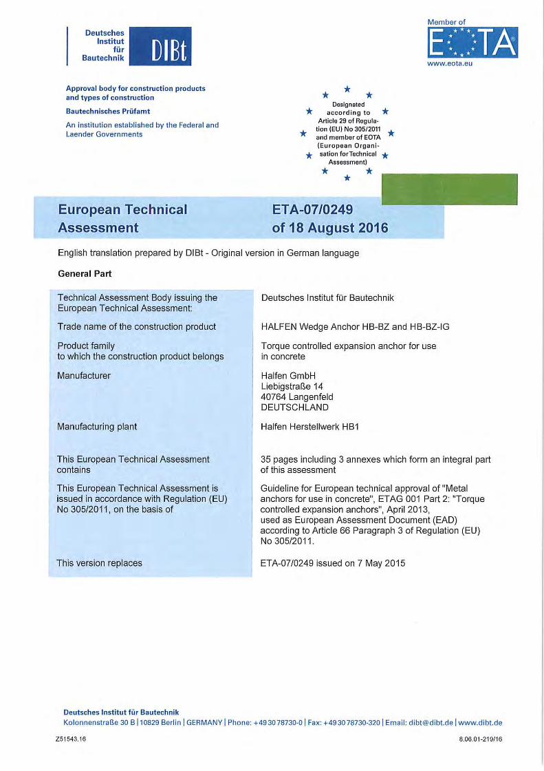
European Technical Assessment
* * * Deslgnaled * a ccording to * Article 29 of Regula-* tion (EU) No 30512011 *
and member of EOTA (European Organi-* saUon forTechnical *
Assessment)
* * *
ETA-07/0249 of 18 August 2016
Member of
www.eota.eu
English translation prepared by DIBt - Original version in German language
General Part
Technical Assessment Body issuing the European Technical Assessment:
Trade name of the construction product
Product family to which the construction product belongs
Manufacturer
Manufacturing plant
This European Technical Assessment contains
This European Technical Assessment is issued in accordance with Regulation (EU) No 305/2011 , on the basis of
This version replaces
Deutsches Institut fü r Bautechnik
Deutsches Institut für Bautechnik
HALFEN Wedge Anchor HB-BZ and HB-BZ-IG
Torque controlled expansion anchor for use in concrete
Halfen GmbH Liebigstraße 14 40764 Langenfeld DEUTSCHLAND
Halfen Herstellwerk H B 1
35 pages including 3 annexes which form an integral part of this assessment
Guideline far European technical approval of "Metal anchors for use in concrete", ETAG 001 Part 2: "Torque controlled expansion anchors", April 2013, used as European Assessment Document (EAD) according to Article 66 Paragraph 3 of Regulation (EU) No 305/2011.
ETA-07/0249 issued on 7 May 2015
Kolonnenstraße 30 B 110829 Berlin 1 GERMANY 1 Phone: +493078730-01 Fax: +493078730-320 1 Email : [email protected] www.dibt.de
Z51543.16 8.06.01-219/16
European Technical Assessment ETA-07/0249 English translation prepared by DIBt
Deutsches Institut
für Bautechnik DIBt
Page 2 of 35 11 B August 2016
The European Technical Assessment is issued by the Technical Assessment Body in its officiallanguage. Translations of this European Technical Assessment in other languages shall fully correspond to the original issued document and shall be identified as such.
Communication of this European Technical Assessment, including transmission by electronic means, shall be in full. However, partial reproduction may only be made with the written consent of the issuing Technical Assessment Body. Any partial reproduction shall be identified as such.
This European Technical Assessment may be withdrawn by the issuing Technical Assessment Body, in particular pursuant to information by the Commission in accordance with Article 25(3) of Regulation (EU) No 305/2011.
Z5 1543.16 8.06.01-219/16
Deutsches Institut
tür Bautechnik OIBt
European Technical Assessment ETA-07/0249 Page 3 of 35118 August 2016
English translation prepared by DIBt
Specific Part
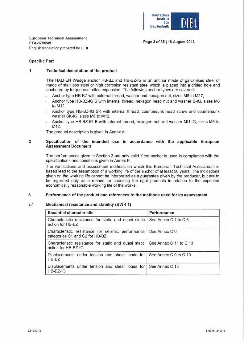
1 Technical description of the product
The HALFEN Wedge anchor HB-BZ and HB-BZ-IG is an anchor made of galvanised steel or made of stainless steel or high corrosion resistant steel which is placed into a drilled hole and anchored by torque-controlled expansion. The following anchor types are covered:
Anchor type HB-BZ with external thread, washer and hexagon nut, sizes M8 to M27, Anchor type HB-BZ-IG S with internal thread, hexagon head nut and washer S-IG, sizes M6 to M12, Anchor type HB-BZ-IG SK with interna I thread, countersunk head screw and countersunk washer SK-IG, sizes M6 to M12, Anchor type HB-BZ-IG B with internal thread, hexagon nut and washer MU-IG, sizes M6 to M12.
The product description is given in Annex A
2 Specification of the intended use in accordance with the applicable European Assessment Document
The performances given in Section 3 are only valid if the anchor is used in compliance with the specifications and conditions given in Annex B.
The verifications and assessment methods on which this European Technical Assessment is based lead to the assumption of a working life of the an chor of at least 50 years. The indications given on the working life cannot be interpreted as a guarantee given by the producer, but are to be regarded only as a means for choosing the right products in relation to the expected economically reasonable working life of the works.
3 Penformance of the product and references to the methods used for its assessment
3.1 Mechanical resistance and stability (BWR 1)
Essential characteristic Penformance
Characteristic resistance for static and quasi static See Annex C 1 to C 5 action for H B-BZ
Characteristic resistance for seismic performance See Annex C 6 categories C1 and C2 for HB-BZ
Characteristic resistance for static and quasi static See Annex C 11 to C 13 action for HB-BZ-IG
Displacements under tension and shear loads for See Annex C 9 to C 10 HB-BZ
Displacements under tension and shear loads for See Annex C 15 HB-BZ-IG
Z51543. 16 8.06.01-219/16
European Technical Assessment ETA-07/0249 Eng lish translation prepared by DISt
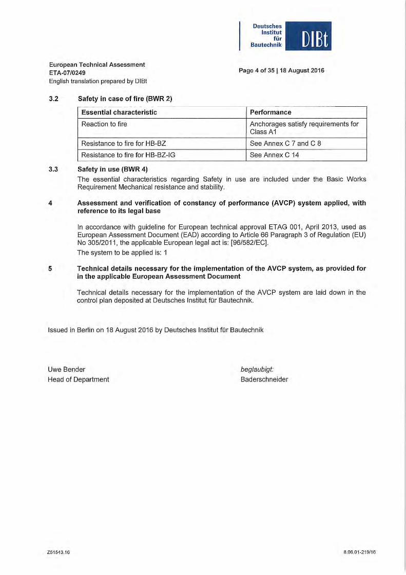
3.2 Safety in case of fire (BWR 2)
Essential characteristic
Reaction to lire
Resistance to lire for HB-BZ
Resistance to lire for HB-BZ-IG
3.3 Safety in use (BWR 4)
Deutsches Institut
für Bautechnik DIBt
Page 4 of 35 118 August 2016
Performance
Anchorages satisfy requirements for Class A1
See Annex C 7 and C 8
See Annex C 14
The essential characteristics regarding Salety in use are included under the Basic Werks Requirement Mechanical resistance and stability.
4 Assessment and verification of constancy of performance (AVCP) system applied, with reference to its legal base
In accordance with guideline lor European technical approval ETAG 001 , April 2013, used as European Assessment Document (EAD) according to Article 66 Paragraph 3 of Regulation (EU) No 305/2011, the applicable European legal act is: [96 /582/EC].
The system to be applied is: 1
5 Technical details necessary for the implementation of the AVCP system, as provided for in the applicable European Assessment Document
Technical details necessary lor the implementation 01 the AVCP system are laid down in the control plan deposited at Deutsches Institut für Bautechnik.
Issued in Berlin on 18 August 2016 by Deutsches Institut lür Bautechnik
Uwe Bender beglaubigt:
Head 01 Department Baderschneider
Z51543.16 8.06.01-219f16
Page 5 of European Technical Assessment ETA-07/0249 of 18 August 2016
English lranslation prepared by DIBI
Wedge an chor HB-BZ
Deutsches Institut
für Bautechnik DlBt
Conical bolt Expansion sleeve Washer Hexagon nut
/ ~;}J-l--o- :: ._. _ ._ . flI MB 10 M20 UI r--
'--
.---,
-!~" I. f ---oiE ~
ß MB 10 M20 ----_":...I !
~
I'---'
".l 8 ---
- 0 M24 10 M27 - _.- ------------------- f- ------ ------(M27 zinc plaled only)
Wedge anchor HB-BZ-IG M6 to M12
Anchor system
HB-BZ-% Washer q- Hexagon
IG S head screw
Conical bolt HB-BZ- -0 Countersunk E3l1- Countersunk IGSK ---0 J ------ .:± - _ was her head screw
"",u" sleeve Commercial Washer Hexagon nut
standard rod HB-BZ- I I I 1GB -} -{}- --IE- -------l-
Anchor version Product descrlptlon Intended use Performance
HB-BZ Annex A 1 - Annex A4 Annex 81 - Annex 86 Annex C1 -Annex C10
HB-BZ-IG AnnexA1 Annex 81 - Annex 82 Annex C 11 - Annex C 15 Annex A5 - Annex A7 Annex 87 - Annex 89
Wedge Anchor HB-BZ and HB-BZ-IG
Product descrlptlon Annex A1 Anchor types
Z51956.16 8 .06.01-219/16
Page 6 of European Technical Assessment ETA-07/0249 of 18 August 2016
English translation prepared by DIBt
Intended use Wedge Anchor HB-BZ
h ~ hm1n " or hm1n,2
I
"I
Wedge Anchor HB-BZ
Product descrlptlon Installation situation HB-BZ
Z51956.16
, , , ,
, I
, ,
h,
- ,- - ,, , , " , , , , ,
, , , ,
Concrete " , ,
, , , , ~ 1-"-- -'--
h ~ hm1n,3
,
Deutsches Institut
für Bautechnik DIBt
Annex A2
8.06.01-219/16
Page 7 of European Technical Assessment ETA-07/0249 of 18 August 2016
English translation prepared by DIBt
Anchor slze HB-BZ MB 10 M20:
Marklng 1 e.g.: <> BZ 15/35 sw
Deutsches Institut
für Bautechnik DlBt
Marklng 1 e.g.: <> BZ 15/35
(1-\ (i! C1J (4. ) <> Identify ing mark of - manufacturing plant
1 BZ Trade name .I / ~ Marking ~ 15 maximum thickness of fixture
'" dk- Wi@MS":;'i+]-I - -o- r-- -.--.-- -'-lF ~tI1@ 35 ~~~'fthickness offixturefor 1 II---<r'---_ f hOf."" 1 Cold formed version '--' M8 Thread diameter
L
Marklng 2 e.g.: <> BZ 15 ,--__ Marking of anchorage depth
I--
·r;:=~=~r:9_~:lr' l_ -__ -.-_-._-. -+"k-;= : = .-=.=1- t=~-
Cold formed version '-
,--
1ßiI.~· :$: '··'1St•·· ::<,~=-;,,_,,-:,=tJ-----------------OI:~r : ~~=-=~- =jl -I:=- ~ Free cut version '--
A4 additional marking of stainless steel
HCR additional marking of high corrosion resistant steel
Marklng 2 e.g.: <> BZ 15
<> Identifying mark of manufacturing plant
BZ Trade name 15 maximum thickness of fixture
for haf M8 Thread diameter
A4 additional marking of stainless steel
HCR additional marking of high corrosion resistant steel
Anchor slze HB-BZ M24 and M27: r--Marklng 3 e.g.: <> BZ M24-30
I <> Identifying mark of n,------. manufacturing plant
BZ Trade name
- --- .8----.- - -- --------·-----·-0-· - ---- __ . ___ ö M24 Thread diameter 30 maximum thickness of fixture A4 additional marking of stainless
Marklng 01 lenglh
Length of anchor min ~
Length of anchor max <
Marklng 01 lenglh
Length of anchor min ~
Length of anchor max <
Wedge Anchor HB-BZ
Producl descrlptlon Anchor sizes and marking
Z51956.16
C (c) o (d)
63,5 76,2
76,2 88,9
0(0) P (p)
215,9 228,6
228 ,6 241,3
E (e) F (I) G (g) H (h)
88,9 101,6 114,3 127,0
101,6 114,3 127,0 139,7
Q (q) R (r) 5 (5) T (I)
241,3 254,0 279,4 304,8
254,0 279,4 304,8 330,2
1 (I) 139,7
152,4
U (u)
330,2
355,6
steel HCR additional marking of high
corrosion resistant steel
J(j) K (k) L (I) M (m) N (n)
152,4 165,1 177,8 190,5 203,2
165,1 177,8 190,5 203,2 215,9
V (v) W(w) X (x) Y (y) Z (z)
355,6 381,0 406,4 431,8 457,2
381 ,0 406,4 431,8 457,2 483,0
Annex A3
8.06.01-219/16
Page 8 of European Technical Assessment ETA-07/0249 of 18 August 2016
English translation p repared by DIBt
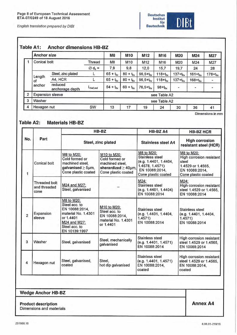
Table A1: Anchor dimensions HB-BZ
Anchor slze MB Ml0
1 Conieal bolt Thread M8 M10
0 dk = 7,9 9,8
Steel, zine plated L 65 + 1,;, 80 + 1,;, Length
A4, HCR L 65 + 1,;, 80 + 1,;, 01 anehor redueed
Lhef,red 54 + Ir. 60 + 1,. anehorage depth
2 Expansion sleeve
3 Washer
4 Hexagon nut SW 13 17
Table A2: Materials HB-BZ
HB-BZ
No. ParI SIeei, zlnc p laled
M8 to M20: M10 to M20: Cold lormed or Cold lormed or
Conical bolt maehined steel, maehined steel, galvanised 2: 5~m, sherardized 2: 40~m,
1 Co ne plastie eoated Cone plastie eoated
Threaded bolt and threaded
M24 and M27: -cone
Steel, galvanised
M8 to M20: Steel ace. to
M10 to M20: EN 10088:2014,
Steel ace. to 2
Expansion material No. 1.4301 EN 10088:2014,
sleeve or 1.4401 material No. 1.4301
M24 and M27: Steel ace. to
or 1.4401
EN 10139:1997
Steel, meehanically 3 Washer Steel, galvanised
galvanised
4 Hexagon nut Steel, galvanised, Steel, eoated hot dip galvanised
Wedge Anchor HB-BZ
Product descrlptlon Dimensions and materials
Z51956.16
Deutsches Institut
für Bautechnik
M12 M16
M12 M16
12,0 15,7
DIBt
M20 M24 M27
M20 M24 M27
19,7 24 28
96,5+1,;, 118+1,;, 137+1,;, 161+1,;, 178+1,;,
96,5+1,;, 118+1,. 137+1,;, 168+1,;, -76,5+1,;, 98+1,;, - - -
see Table A2
see TableA2
19 24 30 36 41
Dimensions in mm
HB-BZA4 HB-BZ HCR
High corroslon Slalnless sleel A4
reslslanl sleel (HCR)
M8 to M20: M8 to M20: Stainless steel High eorrosion resistant (e.g. 1.4401, 1.4404, steel 1.4578, 1.4571) 1.4529 or 1.4565, EN 10088:2014, EN 10088:2014,
Cone plastie eoated Co ne plastie eoated
M24: M24: Stainless steel High eorrosion resistant (e .g. 1.4401, 1.4404) steel 1.4529 or 1.4565, EN 10088:2014 EN 10088:2014
Stainless steel Stainless steel (e .g. 1.4401, 1.4404, (e.g. 1.4401 , 1.4404, 1.4571) 1.4571 ) EN 10088:2014 EN 10088:2014
Stainless steel High eorrosion resistant (e.g . 1.4401, 1.4571) steel 1.4529 or 1.4565, EN 10088:2014 EN 10088:2014
Stainless steel High eorrosion resistant (e.g. 1.4401, 1.4571) stee11.4529 or 1.4565, EN 10088:2014, EN 10088:2014, eoated eoated
Annex A4
8.06.01-219/1 6
Page 9 of European Technical Assessment ETA-07/0249 of 18 August 2016
English translation prepared by DIBt
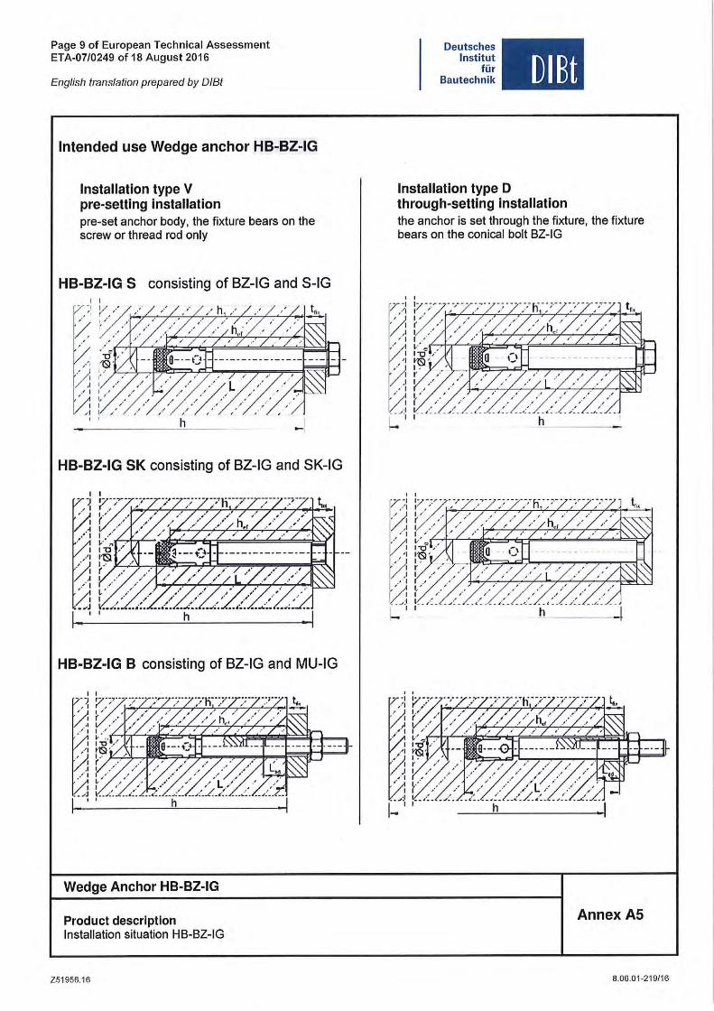
Intended use Wedge anchor HB-BZ-IG
Installation type V pre-seUlng installation pre-set anchor body, the fixture bears on the screw or thread rod only
HB-BZ-IG S consisting of BZ-IG and S-IG
HB-BZ-IG SK consisting of BZ-IG and SK-IG
HB-BZ-IG B consisting of BZ-IG and MU-IG
Wedge Anchor HB-BZ-IG
Product descrlptlon Installation situation HB-BZ-IG
Z51956_16
Deutsches Institut
für Bautechnik DlBt
Installation type D through-setting installation the anchor is set through the fixture, the fixture bears on the conical bolt BZ-IG
, ,
~-I '~--,- - - --,-
. ... I , , I '
I ( )
" I
I
[J: • I
Vi C'
, ,
~-I
/ 1 I .'
I
~ D: ---"-,
Annex A5
8 .06.01~21 9/16
Page 10 of European Technical Assessment ETA-07/0249 of 18 August 2016
English translation prepared by DIBt
Deutsches Institut
tür Bautechnik DlBt
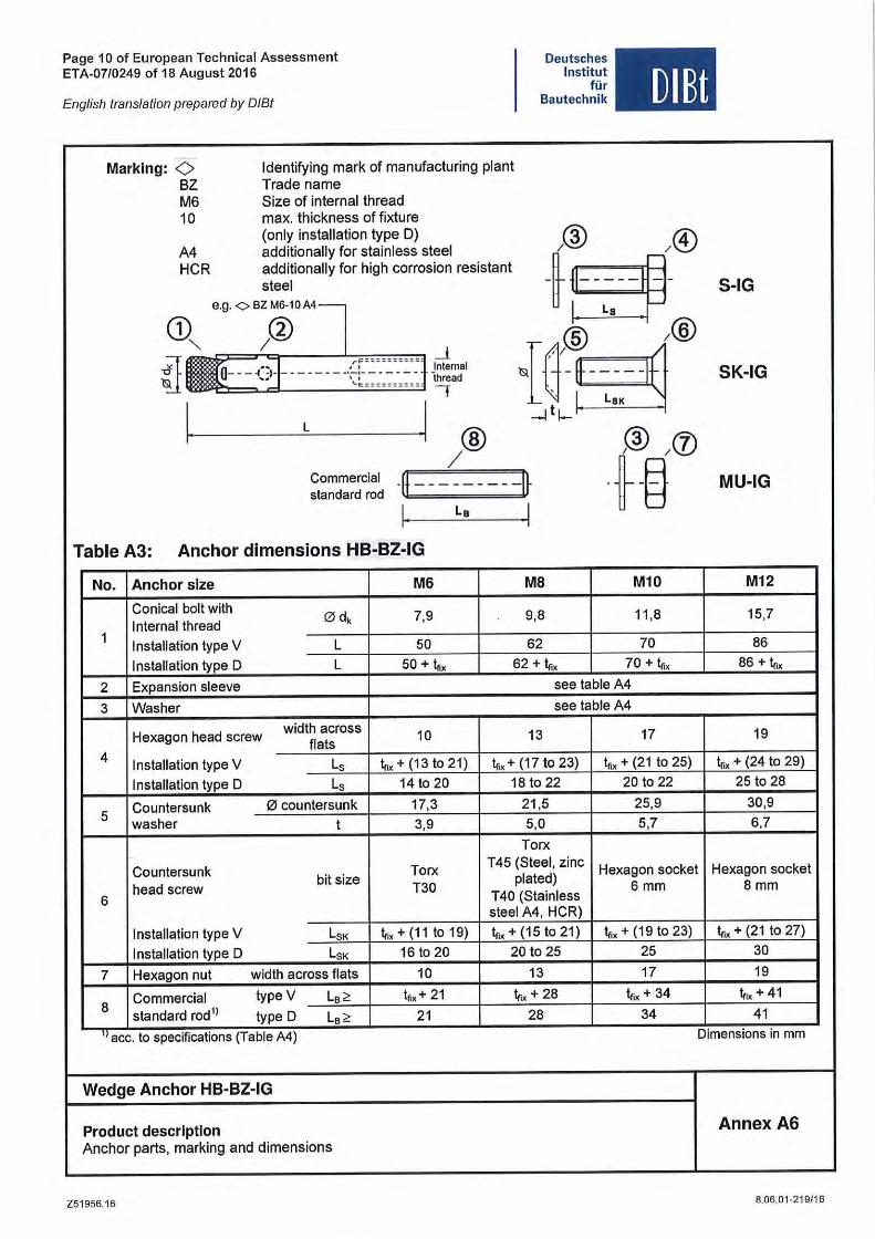
-Marklng: <> Identifying mark of manufacturing plant
BZ Trade name M6 Size of internal thread 10 max. thickness of fixture
(only installation type D) /® )~) A4 additionally for stainless steel HCR additionally for high corrosion resistant
~~-steel S-IG 8.g.0BZM6·10A4-
CD /lJ La
@ /® "- ..l ij - --{~ ------ _.~~ , :l Jntemal {~-~ SK-IG Ihread
'I
I I -ltl-
L
® @ in / I
. ~-§ Commercial '11- -- -- -- --I~ MU-IG standard rod
I L. I Table A3: Anchor dimensions HB-BZ-IG
No. Anchor slze M6 MB M10 M12
Conical bolt with o dk 7,9 9,8 11,8 15,7 Internal thread
1 Installation type V L 50 62 70 86
Installation type D L 50 + 1,;, 62 + Ir~ 70 + 1,;, 86 + 1,;,
2 Expansion sleeve see table A4
3 Washer see table A4
Hexagon head screw width across
10 13 17 19 flats
4 Installation type V Ls Ir~ + (13 to 21) 1,;, + (17 to 23) 1,;, + (21 to 25) 1,;, + (24 to 29)
Installation type D Ls 14 to 20 18 to 22 20 to 22 25 to 28
5 Countersunk o countersunk 17,3 21,5 25,9 30,9 washer t 3,9 5,0 5,7 6,7
Torx
Countersunk Torx T45 (Steel, zinc Hexagon socket Hexagon socket
head screw bit size
T30 plated)
6 mm 8mm 6 T 40 (Stainless
steel A4, HCR)
Installation type V LSK 1,;, + (11 to 19) Ir~ + (15 to 21) 1,;, + (19 to 23) 1,;, + (21 to 27)
Installation type D LSK 16 to 20 20 to 25 25 30
7 Hexagon nut width across flats 10 13 17 19
8 Commercial type V L. ;, 1,;, + 21 1,;, + 28 tfix + 34 1,;, + 41 standard radI) type D L. ;, 21 28 34 41
" ace. to specifications (Table A4) Dimensions in mm
Wedge Anchor HB-BZ-IG
Product descrlptlon Annex A6 Anchor parts, marking and dimensions
Z51956.16 8.06.01 -219/1 6
Page 11 of European Technical Assessment ETA-07/0249 of 18 August 2016
English translation prepared by DIBt
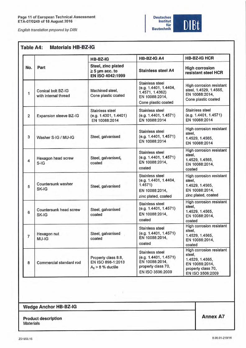
Table A4: Materials HB-BZ-IG
HB-BZ-IG
No_ Part 5teel, zlnc plated 2: 5 11m acc_ to EN ISO 4042:1999
1 Conical bol! BZ-IG Machined steel, with internal thread Cone plastic coated
Stainless steel 2 Expansion sleeve BZ-IG (e.g. 1.4301 , 1.4401)
EN 10088:2014
3 Was her S-IG I MU-IG Steel, galvanised
Hexagon head screw Steel, galvanised, 4
S-IG coated
Countersunk washer 5 Steel, galvanised
SK-IG
Countersunk head screw Steel, galvanised 6
SK-IG coated
Hexagon nut Steel, galvanised 7
MU-IG coated
Property class 8.8, 8 Commercial standard rod EN ISO 898-1 :2013
A, > 8 % ductile
Wedge Anchor HB-BZ-IG
Product descrlptlon Materials
Z51956.16
Deutsches Institut
für Bautechnik
HB-BZ-IG A4
5talnless steel A4
Stainless steel (e.g. 1.4401, 1.4404, 1.4571 , 1.4362) EN 10088:2014,
Cone plastic coated
Stainless steel (e.g. 1.4401, 1.4571) EN 10088:2014
Stainless steel (e.g. 1.4401, 1.4571) EN 10088:2014
Stainless steel (e.g. 1.4401 , 1.4571) EN 10088:2014,
coated
Stainless steel (e.g. 1.4401, 1.4404, 1.4571)
EN 10088:2014,
zinc plated, coated
Stainless steel (e.g. 1.4401, 1.4571)
EN 10088:2014,
coated
Stainless steel (e.g. 1.4401, 1.4571) EN 10088:2014,
coated
Stainless steel (e.g. 1.4401 , 1.4571) EN 10088:2014, property class 70,
EN ISO 3506:2009
DIEt
HB-BZ-IG HCR
High corroslon reslstant steel HCR
High corrosion resistant steel , 1.4529, 1.4565, EN 10088:2014, Cone plastic coated
Stainless steel (e.g. 1.4401 , 1.4571) EN 10088:2014
High corrosion resistant steel, 1.4529, 1.4565, EN 10088:2014
High corrosion resistant steel , 1.4529, 1.4565, EN 10088:2014, coated
High corrosion resistant steel , 1.4529, 1.4565, EN 10088:2014, zinc plated , coated
High corrosion resistant steel , 1.4529, 1.4565, EN 10088:2014, coated High corrosion resistant steel, 1.4529, 1.4565, EN 10088:2014, coated High corrosion resistant steel, 1.4529, 1.4565, EN 10088:2014, property class 70, EN ISO 3506:2009
Annex A7
8.06.01-219/16
Page 12 of European Technical Assessment ETA-07/0249 of 18 August 2016
English lranslation prepared by 0181
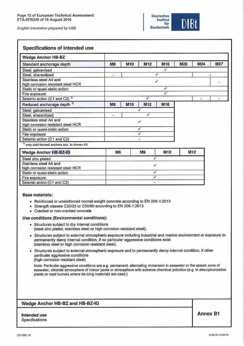
Specifications of intended use
Wedge Anchor HB-BZ
Standard anchorage depth
Steel, galvanised Steel , sherardized Stainless steel A4 and hiah corrosion resistant steel HCR Static or quasi-static action Fire exposure Seismic action (C 1 and C2) 'I
Reduced anchorage depth 1)
Steel, galvanised Steel, sherardized Stainless steel A4 and high corrosion resistant steel HeR Static or quasi-static action Fire exposure Seismic action (C 1 and C2) I) only cold formed anchors acc. to Annex A3
Wedge Anchor f!B-BZ-IG
Steel zinc plated Stainless steel A4 and high corrosion resistant steel HCR Static or Quasi-static action Fire exposure Seismic action (C 1 and C2)
Base materials:
MB I
-
MB I -
M6
I
I
M10 I
M10 I ./
./
./
./
-
Deutsches Institut
für Bautechnik
M12 I M16 ./
./
./
./
./
./
M12 I M16
./
I MB I M10 ./
./
./
./
-
• Reinforced or unreinlorced normal weight conerete aeeording to EN 206-1 :2013 • Strength elasses C20/25 to C50/60 aecording to EN 206-1 :2013 • Craeked or non-eraeked eonerete
Use condltlons (Environmental condltlons):
• Struetures subjeet to dry internal eonditions (steel zine plated, stainless steel or high eorrosion resistant steel).
DIBt
M20 M24 I M27
I -
I -
- I -
I M12
• Struetures subjeet to external atmospherie exposure including industrial and marine environment or exposure to permanently damp internal condition, il no partieular aggressive eonditions exist (stainless steel or high corrosion resistant steel).
• Struetures subjeet to external atmospheric exposure and to permanently damp internal condition, il other partieular aggressive eonditions (high corrosion resistant steel)
Note: Partieular aggressive conditions are e.g. permanent, alternating immersion in seawater or the splash zone 01 seawater, chloride atmosphere 01 indoor pools or atmosphere with extreme ehemieal pollution (e.g. in desulphurization plants or road tunnels where de-ieing materials are used.)
Wedge Anchor HB-BZ and HB-BZ-IG
Intended use Annex 81 Specilications
Z51956.16 8.06.01-219/16
Page 13 of European Technical Assessment ETA-07/0249 of 18 August 2016
Deutsches Institut
für Bautechnik DlBt English translation prepared by DIBt
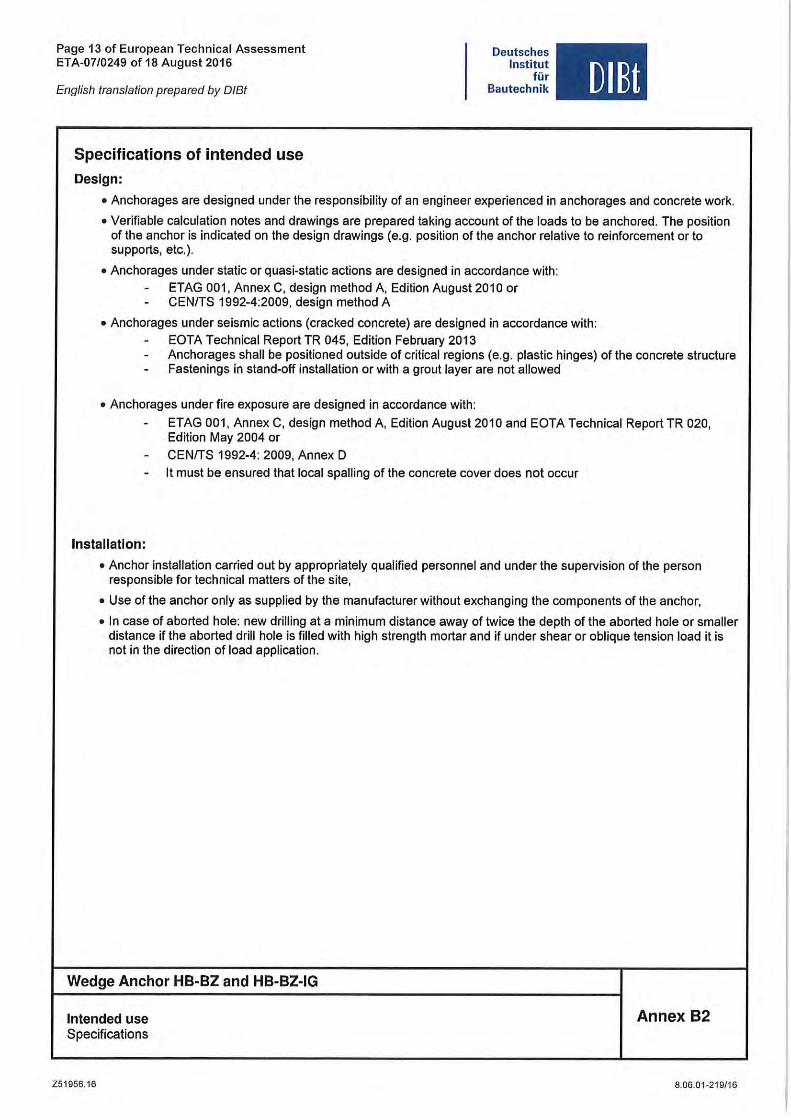
Specifications of intended use
Design:
• Anchorages are designed under the responsibility of an engineer experienced in anchorages and concrete work.
• Veriliable calculation notes and drawings are prepared taking account of the loads to be anchored. The position 01 the anchor is indicated on the design drawings (e.g. position 01 the anchor relative to reinlorcement or to supports, etc.).
• Anchorages under static or quasi-static actions are designed in accordance with: - ETAG 001, Annex C, design method A, Edition August 2010 or - CENITS 1992-4:2009, design method A
• Anchorages under seismic actions (cracked concrele) are designed in accordance with: - EOTA Technical Report TR 045, Edition February 2013 - Anchorages shall be positioned outside 01 critical regions (e.g. plastic hinges) of the concrete structure - Fastenings in stand-off installation or with a graut layer are not allowed
• Anchorages under fire exposure are designed in accordance with:
- ETAG 001, Annex C, design method A, Edition August 2010 and EOTA Technical Report TR 020, Edition May 2004 or
- CENITS 1992-4: 2009, Annex 0
- It must be ensured that local spalling of the concrete cover does nol occur
Installation:
• Anchor installation carried out by appropriately qualilied personnel and under the supervision of the person responsible for technical matters 01 the site,
• Use of the anchor only as supplied by the manulacturer without exchanging the components of the anchor,
• In case of aborted hole: new drilling at a minimum distance away 01 twice the depth of the aborted hole or smaller distance il the aborted drill hole is filled with high strength mortar and if under shear or oblique tension load it is nol in the direction of load application.
Wedge Anchor HB-BZ and HB-BZ-IG
Inlended use Specificalions
Z51956.16
Annex 82
8.06.01-219/1 6
Page 14 of European Technica l Assessment ETA-07/0249 of 18 August 2016
English translation prepared by 0 181
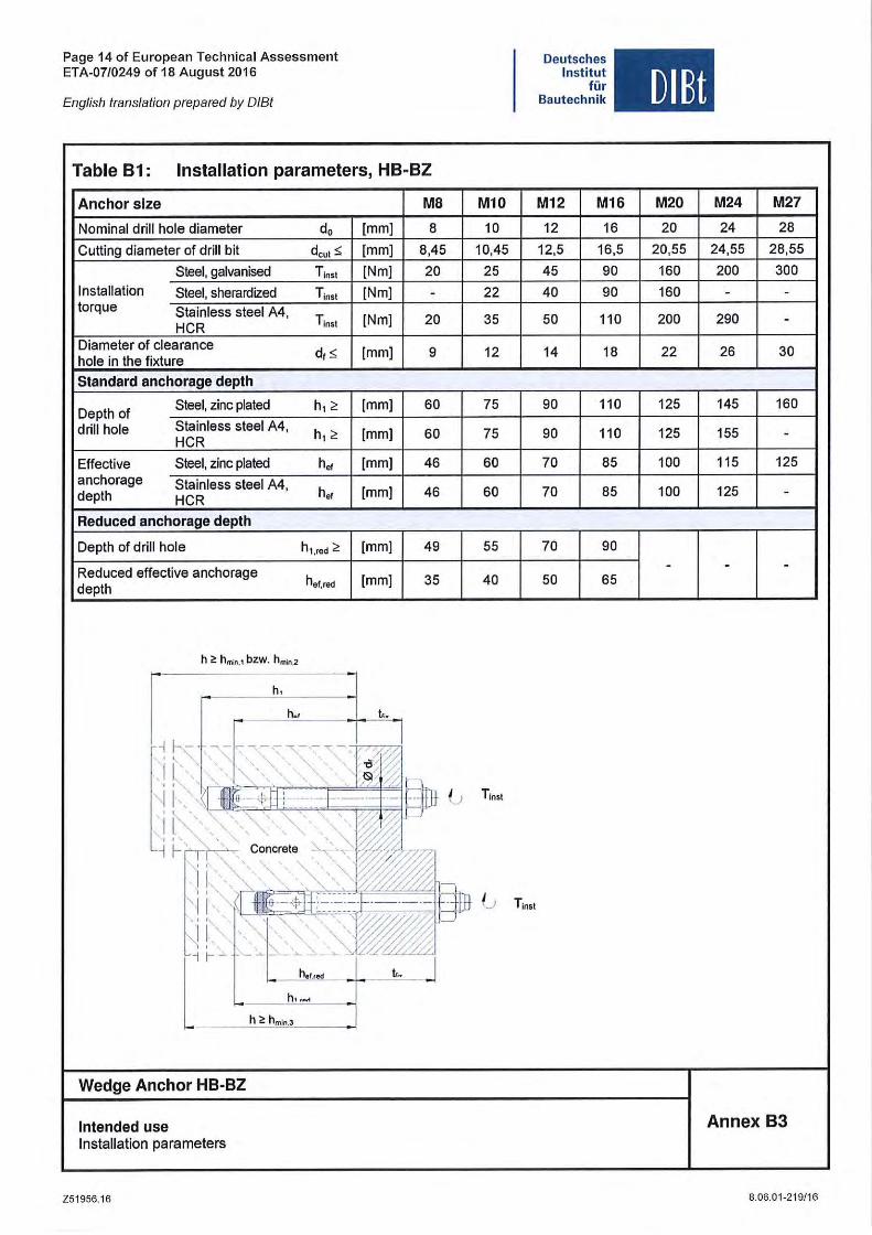
Table 81: Installation parameters, H8-8Z
Anchor slze M8
Nominal drill hole diameter do [mm] 8
Cutting diameter of drill bit d eut< [mm] 8,45
Steel, galvanised T lnsl [Nm] 20 Installation Steel, sherardized T ins! [Nm] -torque Stainless steel A4,
HCR T lnst [Nm] 20
Diameter of clearance df $ [mm] 9
hole in the fixture
Standard anchorage depth
Depth of Steel, zinc plated h, ;, [mm] 60
drill hole Stainless steel A4, h,;, [mm] 60
HCR
Effective Steel, zinc plated h. f [mm] 46 anchorage Stainless steel A4,
h.f [mm] depth HCR 46
Reduced anchorage depth
Depth of drill hole h"red ~ [mm] 49
Reduced effective anchorage depth hef,red [mm] 35
h ~ hmin .1 bzw. hmin2
h , : I h,., .. t. ..
,i ~,~ ~'~~~~-',~~~ " • .\ '0 . '.6 @W
,! :" ;"'~',.~"'.~ G _~ K', Conerete '0 ',."
M10
10
10,45
25
22
35
12
75
75
60
60
55
40
T lnst
I .~i! ~ '\~~_ :! I· 'o ~l ll & -+[ .-@n G
' i I""'" E ~ ~ ~ f~:"~-~-'_\' ~;/~ h...... t... I
h'.M
h > hml, .,
Wedge Anchor HB-BZ
Intended use Installation parameters
Z51956.16
T insl
Deutsches Institut
für Bautechn ik
M12 M16
12 16
12,5 16,5
45 90
40 90
50 110
14 18
90 110
90 110
70 85
70 85
70 90
50 65
DlBt
M20 M24 M27
20 24 28
20,55 24,55 28,55
160 200 300
160 - -200 290 -
22 26 30
125 145 160
125 155 -100 115 125
100 125 -
- - -
Annex 83
8.06.01-219/16
Page 15 of European Technical Assessment ETA-07/0249 of 18 August 2016
English translation prepared by DIBt
Deutsches Institut
tür Bautechnik DIEt
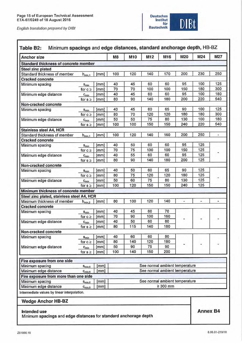
Table 82: Minimum spacings and edge distances, standard anchorage depth, HB-BZ
Anehor slze MB Ml0 M12 M16 M20 M24 M27
Slandard Ihlekness 01 eonerele member
Sleel zlnc plaled Standard thickness of member hmin 1 [mml [ 100 120 140 [ 170 I 200 230 250 Craeked eonerele Minimum spacing Smin [mm] 40 45 60 60 95 100 125
for e " [mm] 70 70 100 100 150 160 300 Minimum edge distanee emin [mm] 40 45 60 60 95 100 160
for s " [mm] 60 90 140 160 200 220 540 Non-eraeked eonerele Minimum spaeing Smin [mm] 40 45 60 65 90 100 125
for e " [mm] 60 70 120 120 160 160 300 Minimum edge distance e min jmm] 50 50 75 60 130 100 160
for s " [mm] 100 100 150 150 240 220 540 Slainiess sleel A4, HCR Standard thickness of member hmin 1 [mm] 100 I 120 I 140 160 200 I 250 I -Craeked eonerele Minimum spaeing Smin [mm] 40 50 60 60 95 125
for e " [mm] 70 75 100 100 150 125 -Minimum edge distanee emin [mm] 40 55 60 60 95 125
for s " [mm] 60 90 140 160 200 125 Non-eracked eonerele Minimum spaeing Smin [mm] 40 50 60 65 90 125
for e " [mm] 60 75 120 120 160 125 -Minimum edge distanee emin [mm] 50 60 75 60 130 125
for s " [mm] 100 120 150 150 240 125 Minimum Ihlekness 01 eonerele member
Sleel zine plaled, slalnless sleel A4, HCR Minimum thickness of member hm," , I [mm] 60 [ 100 120 I 140 I - - -Craeked eonerele Minimum spaeing Smin [mm] 40 45 60 70
for e " [mm] 70 90 100 160 - - -Minimum edge distanee emin [mm] 40 50 60 60
for s " [mm] 60 115 140 160 Non-eraeked eonerele Minimum spaeing Smin [mm] 40 60 60 60
for e" [mm] 60 140 120 160 - - -Minimum edge distanee emin [mm] 50 90 75 90
for s " [mm] 100 140 150 200
Flre exposure tram one slde Minimum spaeing Sminfi [mm] I See normal ambient temperature Minimum edge distanee c",in fi [mm] I See normal ambient temperature
Fire exposure Irom more Ihan one slde Minimum spacing Sm,"" J [mm] I See normal ambient temperature Minimum edge distanee Gm,"" I [mm] I "300 mm
Intermediate values by linear interpolation.
Wedge Anchor HB-BZ
Intended use Annex 84 Minimum spaelngs and edge dlstanees tor standard anehorage depth
Z51956.16 8.06.01 -219/16
Page 16 of European Technical Assessment ETA-07/0249 of 18 August 2016
English translation prepared by DIBt
Deutsches Institut
tür Bautechnik DIBt
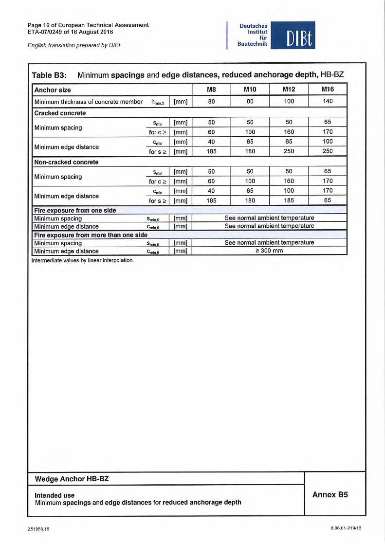
Table B3: Minimum spacings and edge distances, reduced anchorage depth, HB-BZ
Anchor slze MB M10 M12 M16
Minimum thickness of concrete member hmin ,3 [mm] 80 80 100 140
Cracked concrete
Smin [mm] 50 50 50 65 Minimum spacing
for c " [mm] 60 100 160 170
Cmin [mm] 40 65 65 100 Minimum edge distance
for 5 " [mm] 185 180 250 250
Non-cracked concrete
Smln [mm] 50 50 50 65 Minimum spacing
for c " [mm] 60 100 160 170
Cmin [mm] 40 65 100 170 Minimum edge distance
for s " [mm] 185 180 185 65
Flre exposure !rom one slde Minimum spacing Sm'nti I [mm] See normal ambient temperature Minimum edge distance Cminfi I [mm] See normal ambient temperature Flre exposure !rom more than one slde Minimum spacing Sminfi I [mm] See normal ambient temperature Minimum edge distance Cmin fi [mm] ~ 300 mm
Intermediate values by linear interpolation.
Wedge Anchor HB-BZ
Intended use Annex B5 Minimum spaclngs and edge dlstances tor reduced anchorage depth
Z51956.16 8 .06 . 01 ~219/1 6
Page 17 of European Technical Assessment ETA-07/0249 01 18 August 2016
English translation prepared by DIBt
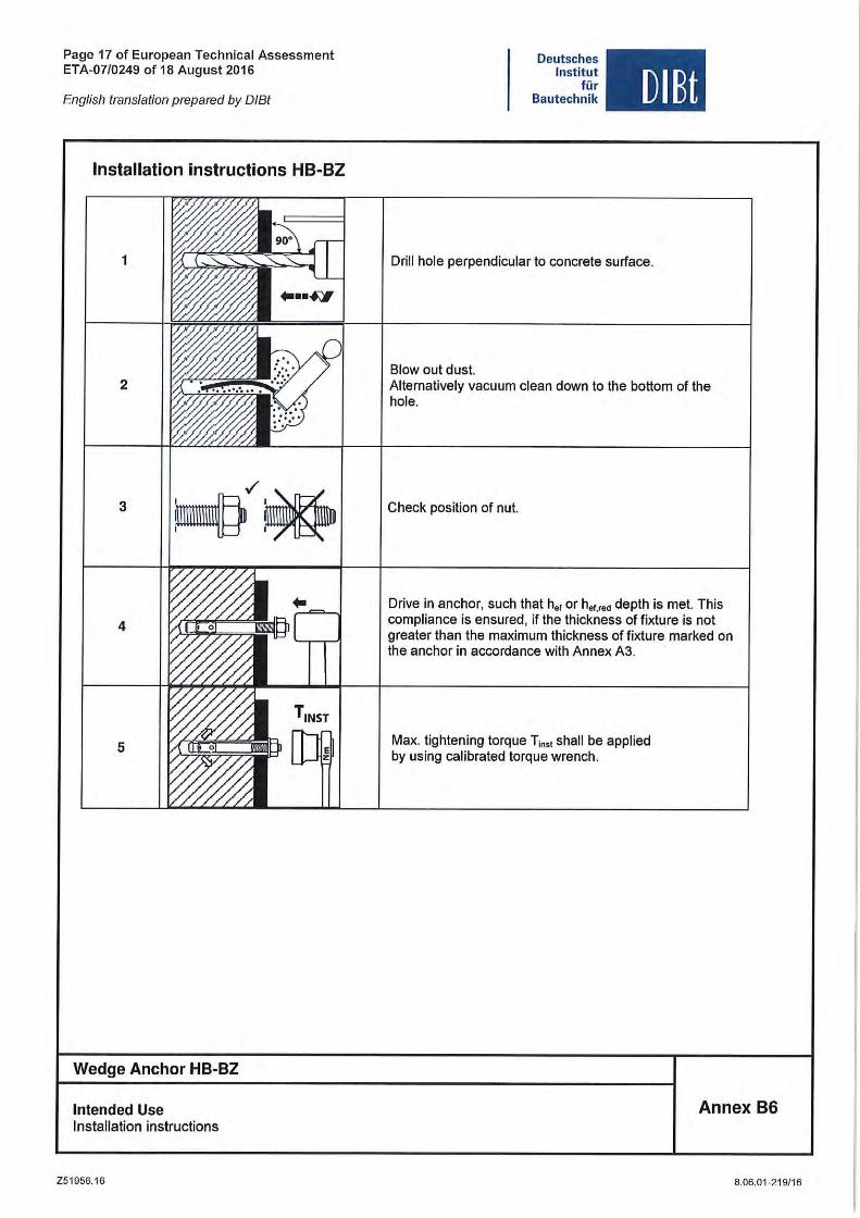
Installation instructions HB-BZ
1
2
3
4
5
Wedge Anchor HB-BZ
Intended Use Installation instructions
Z51956.16
Deutsches Institut
lür Bautechnik DIBt
Drill hole perpendicular to concrete surface.
Blow out dust. Alternatively vacuum clean down to the bottom of the hole.
Check position of nut.
Drive in anchor, such that h'f or h'f.'" depth is met. This compliance is ensured, if the thickness of fixture is not greater than the maximum thickness of fixture marked on the anchor in accordance with Annex A3.
Max. tightening torque T,"" shall be applied by using calibrated torque wrench .
Annex B6
8.06.01-219/16
Page 18 of European Technical Assessment ETA-07/0249 of 18 August 2016
English translation prepared by DIBt
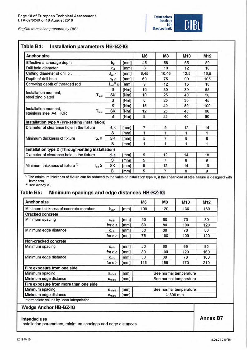
Table B4: Installation parameters HB·BZ·IG
Anchor slze
Effective anchorage depth h" [mm] Drill hole diameter d, [mm] Cutting diameter of drill bit deut< [mm] Depth of drill hole h, ;, [mm] Screwing depth of threaded rod L,.') ;, [mm]
S [Nm] Installation moment, Tinst SK [Nm] steel zinc plated
B [Nm] S [Nm]
Installation moment, Tinst SK [Nm] stainless steel A4, HCR B [Nm]
Installation type V (Pre-selling installation) Diameter of clearance hole in the fixture d, < [mm]
S [mm] Minimum thickness of fixture tr.x t! SK [mm]
B [mm]
Installation type D (Through-selling installation) Diameter of clearance hole in the tixture d,s [mm]
S [mm] Minimum thickness ot tixture 1) ~x t! SK [mm]
B [mm]
M6
45 8
8,45 60 9 10 10 8 15 12 8
7 1 5 1
9 5 9 5
Deutsches Institut
für Bautechnik
MB
58 10
10,45 75 12 30 25 25 40 25 25
9 1 7 1
12 7 12 7
DIBt
M10 M12
65 80 12 16
12,5 16,5 90 105 15 18 30 55 40 50 30 45 50 100 45 60 40 80
12 14 1 1 8 9 1 1
14 18 8 9 14 16 8 9
1) The minimum thickness of fixture can be reduced to the value of installation type V, if the shear load at steel failure is designed with lever arm.
2) see Annex A5
Table B5: Minimum spacings and edge distances HB·BZ·IG
Anchor slze M6 MB M10 M12
Minimum thickness of concrete member hm,o [[mm] 100 120 130 160 Cracked concrete Minimum spacing Smin [mm] 50 60 70 80
tor c ;, [mm] 60 80 100 120 Minimum edge distance Cmin [mm] 50 60 70 80
tor s ;, [mm] 75 100 100 120 Non-cracked concrete Minimum spacing Smin [mm] 50 60 65 80
tor c ;, [mm] 80 100 120 160 Minimum edge distance Cm'o [mm] 50 60 70 100
tor s ;, [mm] 115 155 170 210 Fire exposure trom one side Minimum spacing Smin,fi [mm] See normal temperature Minimum edge distance Cminfi [mm] I See normal temperature Fire exposure trom more than one slde Minimum spacing Sminfi [mm] I See normal temperature Minimum edge distance Cmin,fi [mm] I "300 mm Intermediate values by linear interpolation.
Wedge Anchor HB-BZ-IG
Intended use Annex B7 Installation parameters, minimum spacings and edge distances
Z51956 .16 8.06.01-219/16
Page 19 of European Technical Assessment ETA-07/0249 of 18 August 2016
English lranslation prepared by 0181
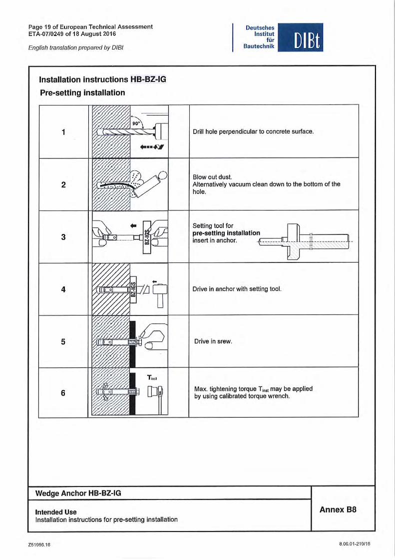
Installation Instructions HB-BZ-IG
Pre-settlng Installation
1
2
3
4
5
6
Wedge Anchor HB-BZ-IG
Intended Use Installation instructions for pre-setting installation
Z51956.16
Deutsches Institut
für Bautechnik OlBt
Drill hole perpendicular to concrete surface.
Blow out dust. Alternatively vacuurn clean down to the bottorn of the hole.
Setting tool for
rnrse~~~~t~~c~~~tallation~_--fr1_ --- . ---if- -------- -- -l
Drive in anchor with setting tool.
Drive in srew.
Max. tightening torque T;"" rnay be applied by using calibrated torque wrench.
Annex B8
8.06.01-219/16
Page 20 of European Technical Assessment ETA-07/0249 of 18 August 2016
English translation prepared by 0/8t
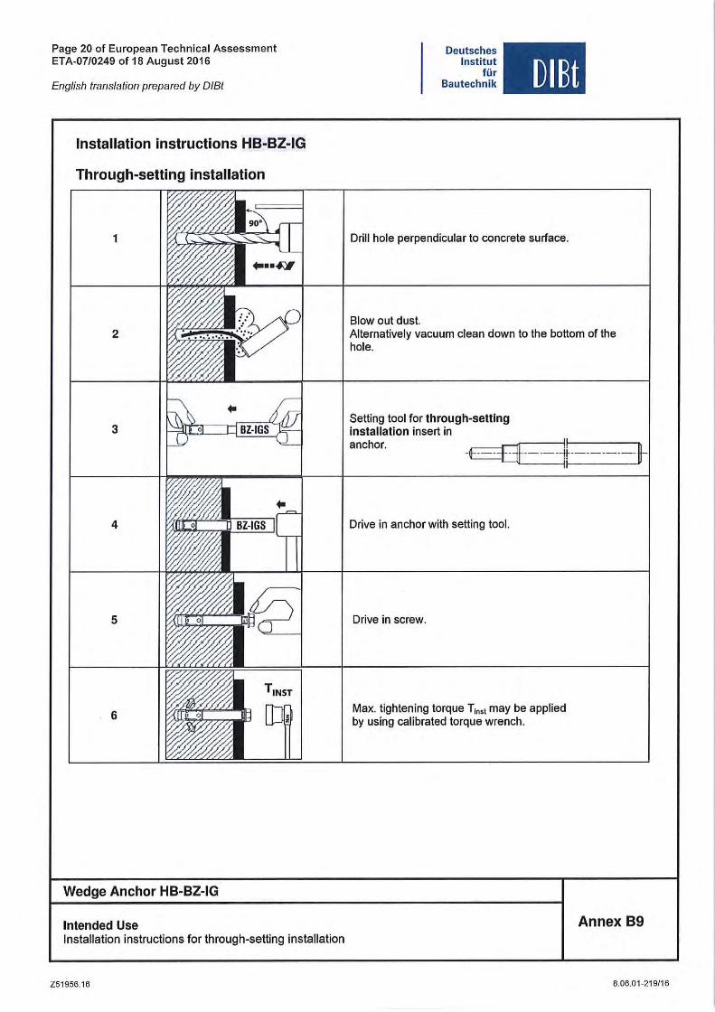
Installation instructions HB-BZ-IG
Through-setting installation
1
2
.. 3
4
5
6
Wedge Anchor HB-BZ-IG
Intended Use Installation instructions for through-setting installation
Z51956.1 6
Deutsches Institut
für Bautechnik DIBt
Drill hole perpendicular to concrete surface.
Blow out dust. Alternatively vacuum clean down to the bottom of the hole .
Setting tool for through-settlng Installation insert in anchor.
Drive in anchor with setting tool.
Drive in screw.
I!
Max. tightening torque T,"" may be applied by using calibrated torque wrench.
Annex B9
6.06.01-219/16
Page 21 01 European Technical Assessment ETA-07/0249 0118 August 2016
English translation prepared by DIBt
Deutsches Institut
für Bautechnik
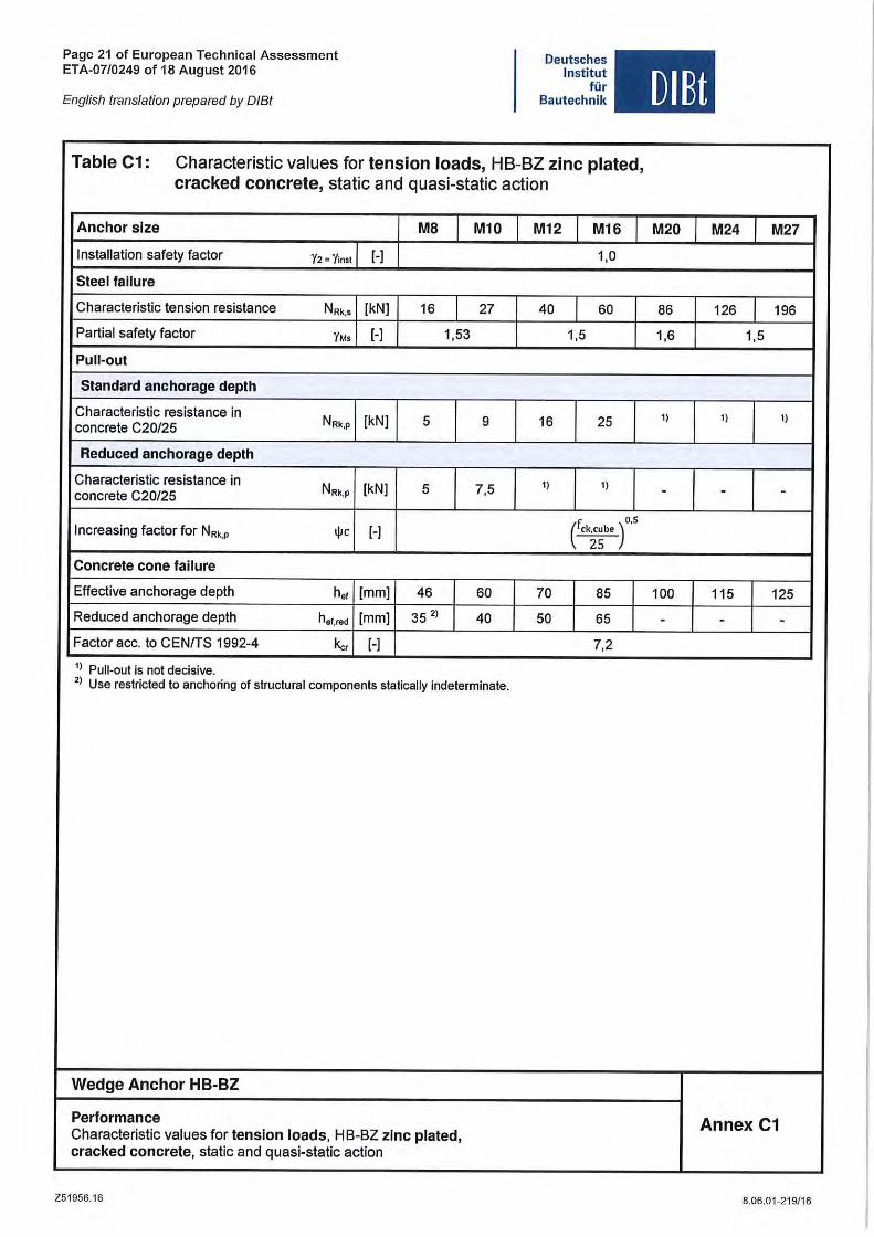
Table C1: Characteristic values for tension loads, HB-BZ zinc plated, cracked concrete, static and quasi-static action
Anchor slze MB M10 M12 M16
Installation salety faetor 12 = 11nst [-) 1,0
Steel failure
Charaeteristie tension resistanee N Rk,$ [kN) 16 27 40 60
Partial safety faetor YM, [-) 1,53 1,5
Pu li-out
Standard anchorage depth
Charaeteristie resistanee in NR. ,. [kN) 5 9 16 25 eonerete C20/25
Reduced anchorage depth
Charaeteristie resistanee in NRk,p [kN) 5 7,5 1) 1)
eonerete C20/25
Inereasing faetor for NR. ,. .pe [-) ( o,S
ck;~be )
Concrete cone fallure
Effeetive anehorage depth hol [mm] 46 60 70 85
Redueed anehorage depth h ef,red [mm] 35 2) 40 50 65
Faetor ace. to CENfTS 1992-4 ka [-I 7,2
1) Pu li-out is not decisive, 2) Use restricted to anchoring of structural components statically indeterminate.
Wedge Anchor HB-BZ
Performance Characteristic values tor tension loads, HB-Bl zlnc plated, cracked concrete, static and quasi-static action
Z51956.16
DlBt
M20 M24 M27
86 126 196
1,6 1,5
1) 1) 1)
- - -
100 115 125
- - -
Annex C1
6.06.01 -219/16
Page 22 of European Technical Assessment ETA-07/0249 of 18 August 2016
English translation prepared by DIBt
Deutsches Institut
für Bautechnik
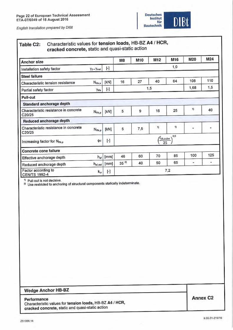
Table C2: Charaeteristie values for tension loads, HB-BZ A4 I HCR, cracked concrete, statie and quasi-statie action
Anehor slze MB M10 M12
Installation safety factor Y2 =Yrnst [-]
Steel failure
Charaeteristie tension resistanee N Rk,1 [kN] 16 27 40
Partial safety faetor 1Ms [-] 1,5
Pu li-out
Standard anehorage deplh
Charaeteristie resistanee in eonerete NRk,p [kN] 5 9 16 C20/25
Redueed anehorBge depth
Charaeteristie resistanee in eonerete NRk,p [kN] 5 7,5 1)
C20/25
DlBt
M16 M20 M24
1,0
64 108 110
1,68 1,5
25 1) 40
1) - -
Inereasing faetor for NR" .pe [-] (ck~~b e )0,5 Conerete co ne failure
Effeetive anehorage depth h.f [mm] 46 60 70 85 100 125
Redueed anehorage depth hef,red [mm] 35 2) 40 50 65 - -Factor aeeording to kc, [-] 7,2 CENfTS 1992-4
1) Pu li-out is not declsive. 2) Use restricted to anchoring of structural components statically indeterminate.
Wedge Anchor HB-BZ
Performance Characteristic values for tension loads, HB-BZ A4/ HCR,
Annex C2
eraeked eonerete, statie and quasi-static action
Z51956.16 8.06.01-219/16
Page 23 of European Technical Assessment ETA-07/0249 of 18 August 2016
Eng/ish translation prepared by DIBt
Deutsches Institut
für Bautechnik
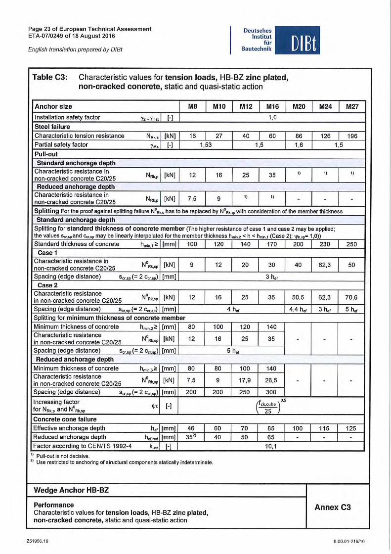
Table C3: Charaeteristie values for tension loads, HB-BZ zine plated,
non-eraeked eonerete, statie and quasi-statie action
Anchor slze M8 M10 M12 M16
Installation salety laetor Y2·Y',,, 1 [-] 1,0
Steel fallure
Charaeteristie tension resistanee NR".I IkN] 16 27 40 1 60 Partial salety laetor YM, I [-] 1,53 1,5
Pu li-out
Standard anehorage depth Charaeteristie resistanee in
NRk,p [kN] 12 16 25 35 non-eraeked eonerete C20/25 Redueed anchorage depth
Charaeteristie resistanee in NRk,p [kN] 7,5 9 1) 1)
non-eraeked eonerete C20/25
DIBt
M20 M24
86 126
1,6 1,5
') 1)
- -Splitting For the proof against splitting failure NORk.c has to be replaced by NORk.'Pwith consideration of the member thickness
Standard anehorage depth Splitting lor standard thiekness of concrete member (The high er resistance of case 1 and case 2 may be applied; the values sa.sp and Ccr.IP may be linearly interpolated for the member thickness hmln•2 < h < hmln.1 (Ca se 2); IVh.SP= 1,0»
Standard thiekness 01 eonerete hmin,1 ~ [mm] 1 100 1 120 140 170 200 230
Case 1 Charaeteristie resistanee in
NORk,sP [kN] 9 12 20 30 40 62,3 non-eraeked eonerete C20/25 Spaeing (edge distanee) sa,.p (- 2 ea,.p) [mm] 3 hof
Case2 Charaeteristie resistanee
NORk.5P IkN] 12 16 25 35 50,5 62,3 in non-eraeked eonerete C20/25 Spaeing (edge distanee) s"" p (- 2 Co."p) Imm] 4 hof 4,4 hof 3 hof Splitting for minimum thiekness of conerete member
Minimum thiekness of eonerete hmin,2 ~ [mm] 80 100 120 140 Charaeteristie resistanee
NORk,sp [kN] 12 16 25 35 in non-eraeked conerete C20/25 - -Spacing (edge distanee) sa,.p (- 2 ea,.p) [mm] 5 hof Redueed anehorage depth
Minimum thiekness of eonerete hmin.3 ~ [mm] 80 80 100 140 Charaeteristie resistanee
NORk,SP [kN] 7,5 9 17,9 26,5 in non-eraeked eonerete C20/25 - -Spacing (edge distanee) s", .. (= 2 ea,.p) [mm] 200 200 250 300
Inereasing laetor ",C [-] (Ck;~bC )0,5
lor NRk,p and N° Rk,'p
Conerete eone failure
Effeetive anehorage depth h" [mm] 46 1 60 70 85 100 115 Redueed anehorage depth her,red [mm] 352) 1 40 50 65 - -Faetor according to CENITS 1992-4 kucr [-] 10,1
1) Pull-out is not decisive. 2) Use restricted to anchoring of structural components statically indeterminate.
Wedge Anchor HB-BZ
M27
196
1)
-
250
50
70,6
5 h"
-
-
125
-
Performance Annex C3 Charaeteristie values lor tension loads, HB-BZ zine plated, non-eraeked eonerete, statie and quasi-statie action
Z51956.16 8.06.01 -219/16
Page 24 of European Technical Assessment ETA-07/0249 of 18 August 2016
English translation prepared by DIBt
Deutsches Institut
fü, Bautechnik
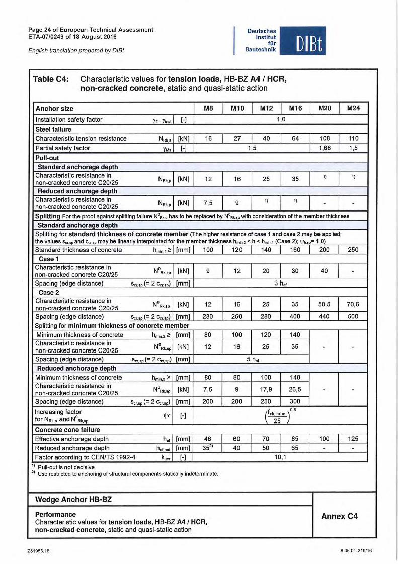
Table C4: Characteristic values for tension loads, HB-BZ A4 I HCR,
non-cracked concrete, static and quasi-static action
Anchor slze MB M10 M12
Installation safety factor y, = y;,,, I [-] 1,0
Steel fallure
Characterislic lension resislance N Rk.s [kN] 16 27 40 I Parlial safely factor YM. [-] 1,5
Pu li-out
Standard anchorage depth Characterislic resislance in
NRk,p [kN] 12 16 25 non-cracked concrete C20/25
Reduced anchorage depth Characterislic resislance in
N Rk.P [kN] 7,5 9 I)
non-cracked concrele C20/25
DlBt
M16 M20 M24
64 108 110
1,68 1,5
35 ') I)
I) - -Splitting For the proof against splitting failure N ORk.c has 10 be replaced by NORk.SP with consideration of the member thickness
Standard anchorage depth Splitting for standard thickness of concrete member (The highe, resistance of case 1 and case 2 may be applied; the values sc .... o and Cer.50 may be linearly interpolated for the member thickness hmn .2 < h < hmln.1 (Gase 2); I.I/h.sp= 1,0)
Standard Ihickness of concrete hmin.1~ [mm] 100 120 140 160 200 250
Case 1 Characlerislic resislance in
NORk,SP [kN] 9 12 20 30 40 non-cracked concrete C20/25 -Spacing (edge distance) s",,, (= 2 c",,,) [mm] 3 h",
Case2 Characteristic resislance in
NORk,SP [kN] 12 16 25 35 50,5 70,6 non-cracked concrele C20/25
Spacing (edge dislance) s",.p (= 2 c"",p) [mm] 230 250 280 400 440 500
Splitting for minimum thickness of concrete member
Minimum Ihickness of concrele h min.2 ~ [mm] 80 100 120 140 Characterislic resislance in
NORk,SP [kN] 12 16 25 35 non-cracked concrete C20/25
- -Spacing (edge dislance) s",.p (- 2 cu"p) [mm] 5 h.f Reduced anchorage depth
Minimum Ihickness of concrele hmin.3 ~ [mm] 80 80 100 140 Characlerislic resislance in
NORk,SP [kN] 7,5 9 17,9 26,5 non-cracked concrele C20/25 - -Spacing (edge dislance) s",,, (= 2 c""p) [mm] 200 200 250 300
Increasing faclor IjIc [-] (ck;~be f'S
for NRk,P and N° Rk,'p
Concrete cone !allure
Effeclive anchorage deplh h'f [mm] 46 60 70 I 85 I 100 125
Reduced anchorage deplh hef,red [mm] 35') 40 50 I 65 I - -Faclor according 10 CENITS 1992-4 1<.." [-] 10,1
1) Pull-out is not decisive. 2) Use restricted to anchoring of structural components statically indeterminate,
Wedge Anchor HB-BZ
Performance Characlerislic values for tension loads, HB-BZ A4/ HeR,
Annex C4
non-cracked concrete, slalic and quasi-stalic aClion
Z51 956.16 8.06.01-219/1 6
Page 25 of European Technical Assessment ETA-07/0249 of 16 August 2016
English translation prepared by DIBt
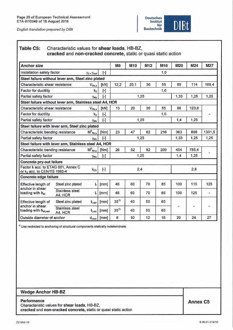
Table C5: Characteristic values for shear loads, HB-BZ,
Deutsches Institut
tür Bautechnik DlEt
cracked and non-cracked concrete, static or quasi static action
Anchor slze M8 M10 M12 M16 M20 M24 M27
Installation safety factor Y2 '" Yins( [-] 1,0
Sleel fallure wilhoul lever arm, Sleel zlnc plated
Characteristic shear resistance VRk,s [kN] 12,2 20,1 30 55 69 114 169,4
Factor for ductility k, [-] 1,0
Partial safety faetor YM, [-] 1,25 1,33 1,25 1,25
Sleel failure wilhoul lever arm, Slalnless steel A4, HGR
Charaeteristie shear resistanee VRk,s [kN] 13 20 30 55 86 123,6
Faetor for duetility k, [-] 1,0 -Partial safety faetor YM' [-] 1,25 1,4 1,25
Sleel failure wilh lever arm, Steel zinc plated
Charaeteristie bending resistanee MORk,S [Nm] 23 47 82 216 363 898 1331,5
Partial safety faetor YM, [-] 1,25 1,33 1,25 1,25
Sleel failure wilh lever arm, Slainiess steel A4, HGR
Charaeteristie bending resistanee MORk,S [Nm] 26 52 92 200 454 765,4 -
Partial safety faetor YM, [-] 1,25 1,4 1,25
Gonerele pry-oul failure
Faetor k ace. to ETAG 001, Annex C ~'I [-] 2,4 2,8
or k, ace. to CENITS 1992-4
Gonerele edge fallure
Effeetive length of Steel zine plated I, [mm] 46 60 70 85 100 115 125 anehor in shear
Stainless steel loading with hOl
A4, HCR I, [mm] 46 60 70 85 100 125 -
Effeetive length of Steel zine plated I,.red [mm] 35'1 40 50 65 anehor in shear
Stainless steel - - -loading with h.
"". A4, HCR I"red [mm] 35'1 40 50 65
Outside diameter of anehor dnom [mm] B 10 12 16 20 24 27
1) Use restricted to anchoring of structural components statically indeterminate.
Wedge Anchor HB-BZ
Performance Characteristie values for shear loads, HB-BZ,
Annex C5
cracked and non-craeked concrele, statie or quasi statie action
Z51956.16 8.06.01-219/16
Page 26 of European Technical Assessment ETA-07/0249 of 18 August 2016
English translation prepared by DIBt
Deutsches Institut
für Bautechnik
Table C6: Characteristic resistance for seismic loading, HB-BZ,
DIBt
standard anchorage depth, performance category C1 and C2
Anchor slze MB Ml0 M12 M16 M20
Tension loads
Installation safety faetor Y2 '" Yinst [-] 1,0
Steel fallure, Steel zlnc plated
Charaeteristie resistanee Cl NRk.s,seis,c1 [kN] 16 27 40 60 86
Charaeteristie resistanee C2 NRk,s,seis.c2 [kN] 16 27 40 60 86
Partial safety factor YMs,seis [-I 1,53 1,5 1,6
Steel fallure, Stalnless steel A4, HCR
Charaeteristie resistanee Cl NRk,s,seis,c1 [kN] 16 27 40 64 108
Charaeteristie resistanee C2 NRk,s,seis,c2 [kN] 16 27 40 64 108
Partial safety faetor YMs,seis [-] 1,5 1,68
Pu li-out (steel zine plated, stainless steel A4 and HCR)
Charaeteristie resistanee Cl NRk,p,seis,c1 [kN] 5 9 16 25 36
Charaeteristie resistanee C2 NRk,p,sels,c2 [kN] 2,3 3,6 10,2 13,8 24,4
Inereasing faetor for NR"p ljic [-I 1,0
Shear loads
Steel fallure wlthout lever arm, Steel zinc plated
Charaeteristie resistanee Cl VRk,s.seis,C1 [kN] 9,3 20 27 44 69
Charaeteristie resistanee C2 V Rk,s,seis,C2 [kN] 6,7 14 16,2 35,7 55,2
Partial safety faetor YMs.seis [-I 1,25 1,33
Steel fall ure wlthout lever arm, Stalnless steel A4, HCR
Charaeteristie resistanee Cl V Rk,s,seis,C 1 [kN] 9,3 20 27 44 69
Charaeteristie resistanee C2 V Rk.s,seis,C2 [kN] 6,7 14 16,2 35,7 55,2
Partial safety factor YMs,&8is [-I 1,25 1,4
Wedge Anchor HB-BZ
Performance Characteristic resistance for selsmlc loadlng, HB-BZ,
Annex C6
standard anchorage depth, performance category Cl and C2
Z51956.16 8.06.01-219/16
Page 27 of European Technical Assessment ETA-07/0249 of 18 August 2016
English translation prepared by DIBt
Deutsches Institut
tür Bautechnik DlBt
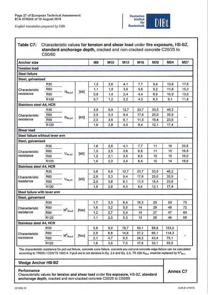
Table C7: Characlerislic values tor tension and shear load under tire exposure, HB-BZ, standard anchorage depth, cracked and non-cracked concrele C20/25 10 C50/60
Anchor slze MB M10 M12 M16 M20 M24 M27
Tension load
Sieel !ailure
SIeei, galvanised
R30 1,5 2,6 4,1 7,7 9,4 13,6 17,6
Characteristic R60 1,1 1,9 3,0 5,6 8,2 11,8 15,3 resistance R90
NRk•S•fi [kN] 0,8 1,4 2,4 4,4 6,9 10,0 13,0
R120 0,7 1,2 2,2 4,0 6,3 9,1 11,8
Slainiess sleel A4, HeR
R30 3,8 6,9 12,7 23,7 33,5 48,2
Characteristic R60 2,9 5,3 9,4 17,6 25,0 35,9
resistance NAk,8.fi [kN] -R90 2,0 3,6 6,1 11,5 16,4 23,6
R120 1,6 2,8 4,5 8,4 12,1 17,4
Shear load
Sieel !ailure wilhoul lever arm
Sieel, galvanised
R30 1,6 2,6 4,1 7,7 11 16 20,6
Characteristic R60 1,5 2,5 3,6 6,8 11 15 19,8 resislance R90
VRk,s,fi [kN] 1,2 2,1 3,5 6,5 10 15 19,0
R120 1,0 2,0 3,4 6,4 10 14 18,6
Slainiess sleel A4, HeR
R30 3,8 6,9 12,7 23,7 33,5 48,2
Characteristic R60 2,9 5,3 9,4 17,6 25,0 35,9
resistance VRk,s,fi [kN] -R90 2,0 3,6 6,1 11,5 16,4 23,6
R120 1,6 2,8 4,5 8,4 12,1 17,4
Sieel !ailure with lever arm
SIeei, .galvanlsed
R30 1,7 3,3 6,4 16,3 29 50 75
Characteristic R60 MO 1,6 3,2 5,6 14 28 48 72 resistance R90
Rk,s,1i [Nm] 1,2 2,7 5,4 14 27 47 69
R120 1,1 2,5 5,3 13 26 46 68
Slalnless sleel A4, HeR
R30 3,8 9,0 19,7 50,1 88,8 153,5
Characteristic R60 MO 2,9 6,8 14,6 37,2 66,1 114,3 [Nm] -
resistance R90 Rk,s,fi
2,1 4,7 9,5 24,2 43,4 75,1
R120 1,6 3,6 7,0 17,8 32,1 55,5
The characteristic resistance tor pul I-out tailure, concrete eone tailure, concrete pry-out and concrete edge tailure can be calculated acoording to TR020 / CENITS 1992-4. 1I pUlt-out is not decisive in Eq. 2.4 and Eq. 2.5, TR 020 N ••. , must be replaced by N° •• ," ..
Wedge Anchor HB-BZ
Performance Annex C7 Charaeteristie values !or lenslon and shear load under !Ire exposure, HB-BZ. slandard anchorage deplh. eraeked and non-eracked eonerete C20/25 to C50/60
Z51956.1 6 8.06.01-219/16
Page 28 of European Technical Assessment ETA-0710249 of 18 August 2016
English translation prepared by DIBt
Deutsches Institut
tür Bautechnik DlBt
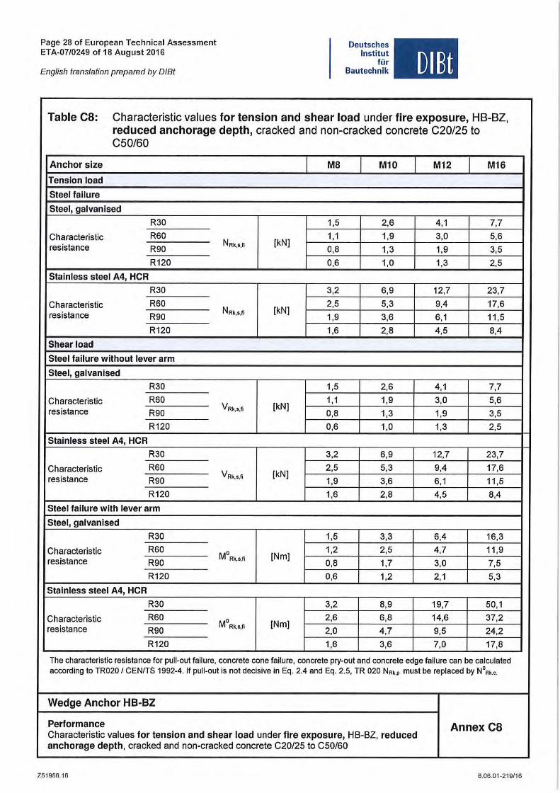
Table ca: Characteristic values tor tension and shear load under tire exposure, HB-BZ, reduced anchorage depth, cracked and non-cracked concrete C20/25 to C50/60
Anchor size MB M10 M12 M16
Tension load
Steet failure
Steet, gatvanised
R30 1,5 2,6 4,1 7,7
Characteristic R60 1,1 1,9 3,0 5,6 resistance R90
NRk,s,fi [kN] 0,8 1,3 1,9 3,5
R120 0,6 1,0 1,3 2,5
Stainless steet A4, HeR
R30 3,2 6,9 12,7 23,7
Characteristic R60 2,5 5,3 9,4 17,6 resistance R90
NRk.s,fi [kN] 1,9 3,6 6,1 11,5
R120 1,6 2,8 4,5 8,4
Shear load
Steet fallure without tever arm
Steel, gatvanised
R30 1,5 2,6 4,1 7,7
Characteristic R60 VRk,s,fi [kN]
1,1 1,9 3,0 5,6 resistance R90 0,8 1,3 1,9 3,5
R120 0,6 1,0 1,3 2,5
Stainless steel A4, HeR
R30 3,2 6,9 12,7 23,7
Characteristic R60 2,5 5,3 9,4 17,6 resistance R90
VRk,s,fi [kN] 1,9 3,6 6,1 11,5
R120 1,6 2,8 4,5 8,4
Steei failure with lever arm
Steet, gatvanised
R30 1,5 3,3 6,4 16,3
Characteristic R60 MO 1,2 2,5 4,7 11,9 resistance R90
Rk,s,fi [Nm] 0,8 1,7 3,0 7,5
R120 0,6 1,2 2,1 5,3
Stainless steet A4, HeR
R30 3,2 8,9 19,7 50,1
Characteristic R60 MO 2,6 6,8 14,6 37,2 resistance R90
Rk,s,fi [Nm] 2,0 4,7 9,5 24,2
R120 1,6 3,6 7,0 17,8
The characteristie resistance for pul I-out failure, concrete cone failure. concrete pry-out and eonerele edge failure can be calculaled according to TR020 I CENfTS 1992-4. II pu li-out is not decisive in Eq. 2.4 and Eq. 2.5, TR 020 No •. , must be replaced by N°o •. ,.
Wedge Anchor HB-BZ
Performance Annex ca Characterislic values for tension and shear load under lire exposure, HB-BZ, reduced anehorage depth, eraeked and non-eracked conerele C20/25 to C50/60
Z51956.16 8. 06.01-219/16
Page 29 of European Technical Assessment ETA-07/0249 of 18 August 2016
English translation prepared by DIBt
Deutsches Institut
tür Bautechnik
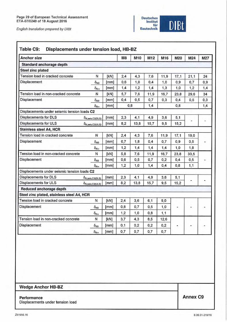
Table C9: Displacements under tension load, HB-BZ
Anchor slze MB Ml0 M12
Standard anchorage depth
Steel zlnc plated
Tension load in cracked concrete N [kN] 2,4 4,3 7,6
Displacement 6NO [mm] 0,6 1,0 0,4
6N• [mm] 1,4 1,2 1,4
Tension load in non-cracked concrete N [kN] 5,7 7,6 11 ,9
Displacement 6NO [mm] 0,4 0,5 0,7
6N• [mm] 0,8 1,4
Displacements under seismic tension loads C2
Displacements for DLS ON,sels.c2(Dl S) [mm] 2,3 4,1 4,9
Displacements for ULS ON,seiS,C2(Ul S) [mm] 8,2 13,8 15,7
Stalnless steel A4, HCR
Tension load in cracked concrete N [kN] 2,4 4,3 7,6
Displacement 6NO [mm] 0,7 1,8 0,4
6N• [mm] 1,2 1,4 1,4
Tension load in non-cracked concrete N [kN] 5,8 7,6 11,9
Displacement 6NO [mm] 0,6 0,5 0,7
6N• [mm] 1,2 1,0 1,4
Displacements under seismic tension loads C2
Displacements for DLS ON.seis.C2(DlS) [mm] 2,3 4,1 4,9
Displacements for ULS ON.seis.C2(Ul S) [mm] 8,2 13,8 15,7
Reduced anchorage depth
Steel zlnc plated, stainless steel A4, HCR
Tension load in cracked concrete N [kN] 2,4 3,6 6,1
Displacement 6NO [mm] 0,8 0,7 0,5
6N• [mm] 1,2 1,0 0,8
Tension load in non-cracked concrete N [kN] 3,7 4,3 8,5
Displacement 6NO [mm] 0,1 0,2 0,2
6N• [mm] 0,7 0,7 0,7
Wedge Anchor HB-BZ
Performance Displacements under tension load
Z51956.16
DlBt
M16 M20 M24 M27
11,9 17,1 21,1 24
1,0 0,9 0,7 0,9
1,3 1,0 1,2 1,4
16,7 23 ,8 29,6 34
0,3 0,4 0,5 0,3
0,8 1,4
3,6 5,1 - -
9,5 15,2
11,9 17,1 19,0
0,7 0,9 0,5 -1,4 1,0 1,8
16,7 23,8 33,5
0,2 0,4 0,5 -0,4 0,8 1,1
3,6 5,1 - -
9,5 15,2
9,0
1,0 - - -1,1
12,6
0,2 - - -0,7
Annex C9
8.06.01-219/16
Page 30 of European Technical Assessment ETA-07/0249 of 18 August 2016
English translation prepared by DIBt
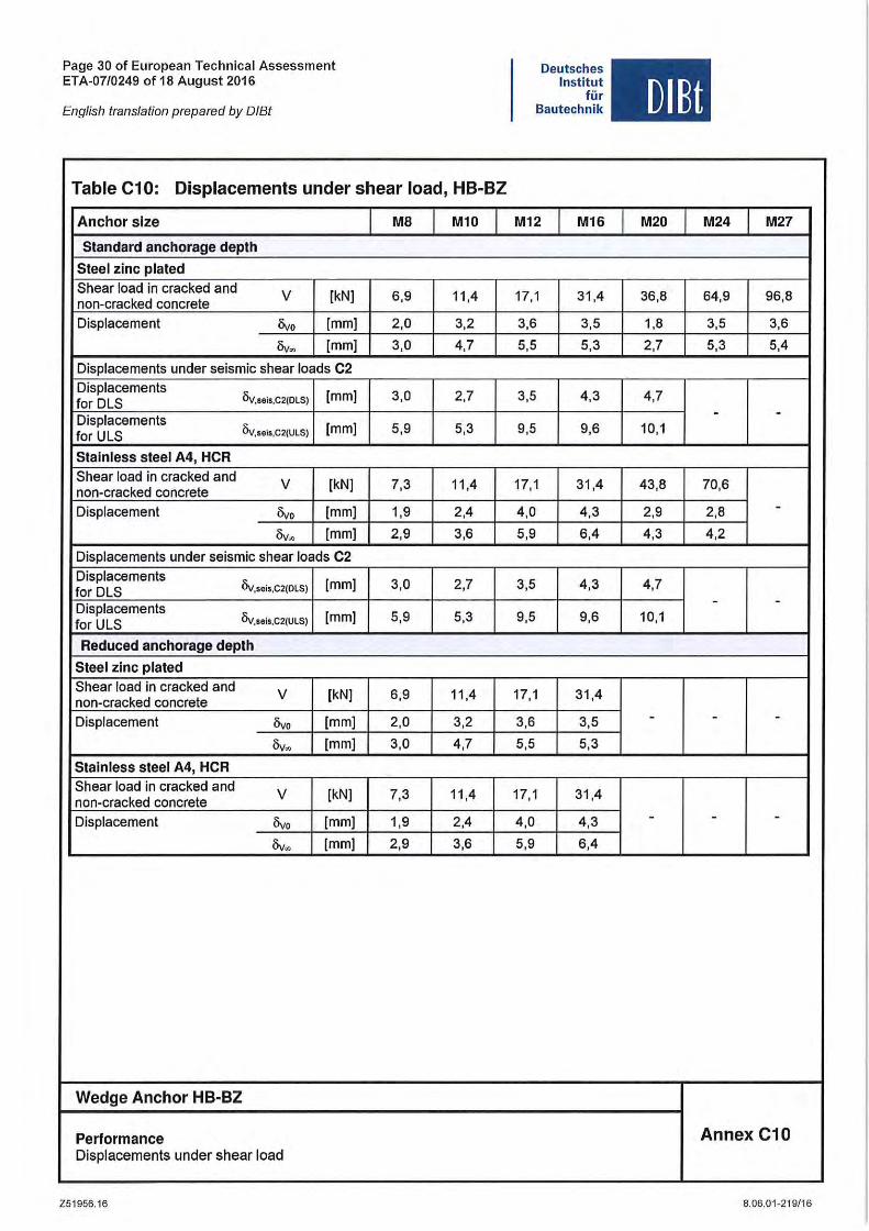
Table C10: Displacements under shear load, HB-BZ
Anchor slze MB M10
Standard anchorage depth
Steel zlnc plated Shear load in cracked and V [kN] 6,9 11,4 non-cracked concrete Displacement Ovo [mm] 2,0 3,2
Ov~ [mm] 3,0 4,7
Displacements under seismic shear loads C2 Displacements
Öv,SOis,C2(DLS) [mm] 3,0 2,7 for DLS Displacements for ULS Öv,soi5,C2(ULS) [mm] 5,9 5,3
Stainless steel A4, HCR Shear load in cracked and V [kN] 7,3 11,4 non-cracked concrete
Displacement Ovo [mm] 1,9 2,4
Öv. [mm] 2,9 3,6
Displacements under seismic shear loads C2 Displacements
Öv,sois,C2(DLS) [mm] 3,0 2,7 for DLS Displacements for ULS Öv,seis,C2(ULS) [mm] 5,9 5,3
Reduced anchorage depth
Steel zlnc plated Shear load in cracked and V [kN] 6,9 11,4 non-cracked concrete Displacement Ovo [mm] 2,0 3,2
Ov. [mm] 3,0 4,7
Stainless steel A4, HCR Shear load in cracked and
V [kN] 7,3 11,4 non-cracked concrete Displacement Ovo [mm] 1,9 2,4
Öv. [mm] 2,9 3,6
Wedge Anchor HB-BZ
Performance Displacements under shear load
Z51956.16
Deutsches Institut
tür Bautechnik
M12 M16
17,1 31,4
3,6 3,5
5,5 5,3
3,5 4,3
9,5 9,6
17,1 31,4
4,0 4,3
5,9 6,4
3,5 4,3
9,5 9,6
17,1 31,4
3,6 3,5
5,5 5,3
17,1 31,4
4,0 4,3
5,9 6,4
DlBt
M20 M24 M27
36,8 64,9 96,8
1,8 3,5 3,6
2,7 5,3 5,4
4,7 - -
10,1
43,8 70,6
2,9 2,8 -4,3 4,2
4,7 - -
10,1
- - -
- - -
Annex C10
8.06.01-219/16
Page 31 of European Technical Assessment ETA-07/0249 of 18 August 2016
English translation prepared by DIBt
Deutsches Institut
für Bautechnik
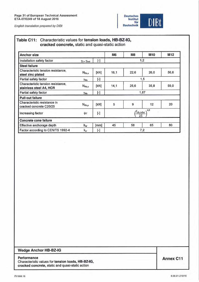
Table C11: Characteristic values for tension loads, HB-BZ-IG, eraeked conerete, static and quasi-static action
Anchor slze M6 I MB
Installation safety factor Y2 = Ylns! [-)
Steel failure
Characteristic tension resistance, N Rk,$ [kN) 16,1 I 22,6
sleel zinc plaled
Partial safety factor 1M, [-)
Characteristic tension resistance, NRk•s [kN) 14,1 I 25,6
slalnless sleel A4, HCR
Partial safety factor 1M, [-)
Pull-oul fallure
Characteristic resistance in NRk.p [kN) 5 I 9
cracked concrete C20/25
DIBt
I M10 I 1,2
I 26,0 I 1,5
I 35,8 I 1,87
I 12 I Increasing factor tjlc [-)
( o,S ck~~b e )
Concrele co ne lallure
Effective anchorage depth h.f [mm) 45 I 58 I 65 I Factor according to CEN/TS 1992-4 1<., [-) 7,2
Wedge Anchor HB-BZ-IG
Performance Characteristic values for tension loads, HB-BZ-IG, cracked concrele, static and quasi-static action
Z51956.16
M12
56,6
59,0
20
80
Annex C11
8.06.01-219/16
Page 32 of European Teehnieal Assessment ETA-07/0249 of 18 August 2016
English Iranslation prepared by 0181
Deutsches Institut
für Bautechnik DlBt
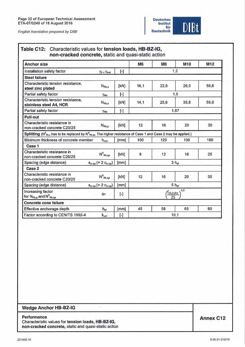
Table C12: Characteristic values for tension loads, HB-BZ-IG, non-cracked concrete, static and quasi-static action
Anchor slze M6 I MB I Ml0 I Installation safety faetor 12 " Yinst H 1,2
Sleel fallure
Charaeteristie tension resistanee, NRk,s [kN ) 16,1 I 22,6 I 26,0 I sleel zinc plated
Partial safety faetor 1M, [-) 1,5
Charaeteristie tension resistanee, NRk ,$ [kN) 14,1 I 25,6 I 35,8 I slainless sleel A4, HCR
Partial safety factor 1M, [-I 1,87
Pull-oul
Charaeteristie resistanee in NRk,P [kN) 12 I 16 I 20 I non-eraeked eonerete C20/25
Splitting (N°".< has to be replaeed by NO"." . The higher resistanee of Case 1 and Ca se 2 may be applied.)
Minimum thiekness of eonerete member hmin [mm) 100 I 120 I 130 I Ca se 1
Charaeteristie resistanee in NORk,SP [kN) 9 I 12 I 16 I non-eraeked conerete C20/25
Spacing (edge distanee) s cr,sp (= 2 ccr,sp) [mm) 3 h'f
Case 2
Charaeteristie resistanee in NORk,SP [kN) 12 J 16 I 20 I non-eraeked eonerete C20/25
Spaeing (edge distanee) scr,sp (= 2 Ccr.sp) [mm) 5 h'f
Inereasing faetor ( 0,5
for NRk,P and N° Rk,sp IjIc [-) ck~~be )
Concrele co ne fallure
Effeetive anehorage depth h'f [mm) 45 I 58 I 65 I Faetor aeeording to CENITS 1992-4 k." [-) 10,1
Wedge Anchor HB-BZ-IG
Performance Charaeteristie values for tension loads, HB-BZ-IG, non-cracked concrete, statie and quasi-statie action
Z51956.16
M12
56,6
59,0
30
160
25
30
80
Annex C12
8.06.01-219/16
Page 33 of European Technical Assessment ETA-07/0249 of 18 August 2016
English Iranslalion prepared by 0181
Deutsches Institut
tür Bautechnik
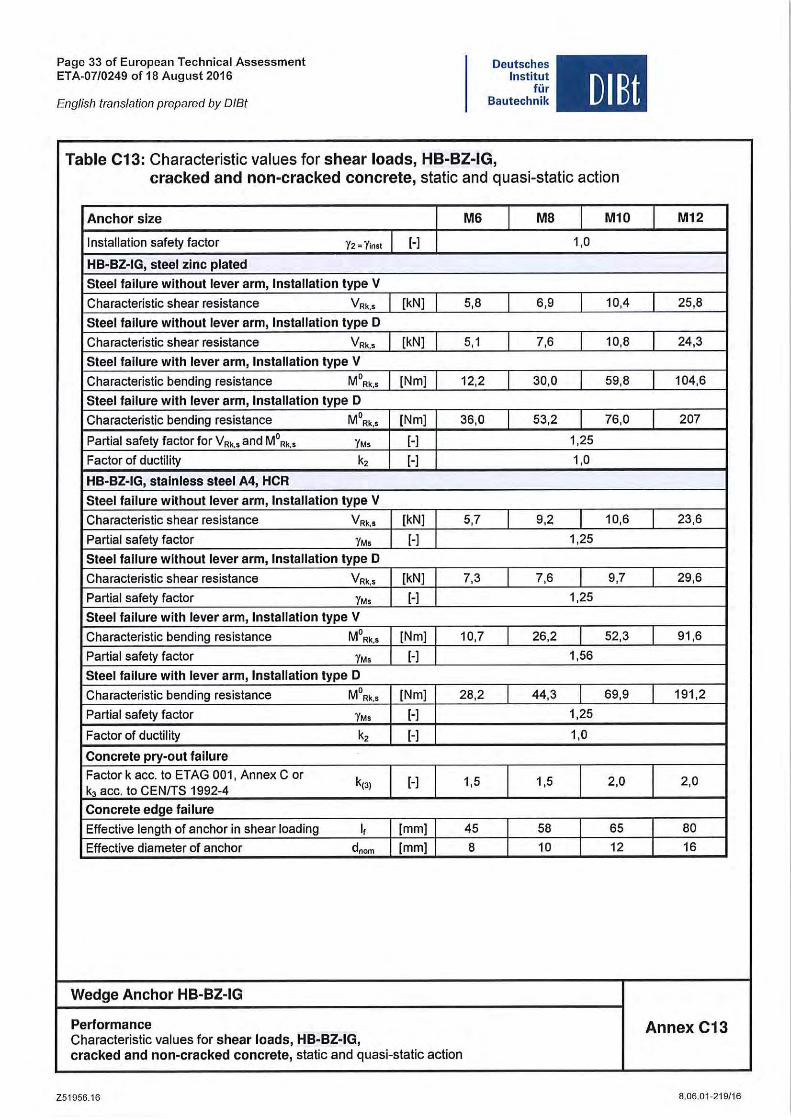
Table C13: Characteristic values for shear loads, HB-BZ-IG,
DlBt
cracked and non-cracked concrete, static and quasi-static action
Anehor slze M6 M8 M10
Installation safety faetor Y2 · Y'nst [-] 1,0
HB-BZ-IG, steel zlne plated
Steel fallure without lever arm, Installation type V
Charaeteristie shear resistanee V Rk,s [kN] 5,8 6,9 10,4
Steel fallure without lever arm, Installation type 0
Charaeteristie shear resistanee VRk,iS [kN] 5,1 7,6 10,8
Steel fallure with lever arm, Installation type V
Charaeteristie bending resistanee MORk,s [Nm] 12,2 30,0 59,8
Steel fallure with lever arm, Installation type 0
Charaeteristie bending resistanee M ORkl [Nm] 36,0 53 ,2 76,0
Partial safety faetor for VR,. and MORk,. YM. [-] 1,25
Faetor of duetility k, [-] 1,0
HB-BZ-IG, stalnless steel A4, HeR
Steel fallure withoutlever arm, Installation type V
Charaeteristie shear resistanee VRk.1 [kN] 5,7 9,2 10,6
Partial safety faetor YM. [-] 1,25
Steel fallure without lever arm, Installation type 0
Charaeteristie shear resistanee VRk.s [kN] 7,3 7,6 9,7
Partial safety faetor YM. [-] 1,25
Steel fallure with lever arm, Installation type V
Charaeteristie bending resistanee MORk,. [Nm] 10,7 26,2 52,3
Partial safety faetor YM. [-] 1,56
Steel fallure with lever arm, Installation type 0
Charaeteristie bending resistanee M ORk, ! [Nm] 28,2 44,3 69,9
Partial safety faetor YM. [-] 1,25
Faetor of duetility k, [-] 1,0
Conerete pry-out fallure
Factor k ace, to ETAG 001, Annex C or k(3) [-] 1,5 1,5 2,0
k, ace, to CENITS 1992-4
Conerete edge fallure
Effeetive length of anehor in shear loading I, [mm] 45 58 65
Effeetive diameter of anehor d,om [mm] 8 10 12
Wedge Anchor HB-BZ-IG
Performance Charaeteristic values for shear loads, HB-BZ-IG, eraeked and non-cracked conerete, stalie and quasi-slalie aelion
Z51956,16
M12
25,8
24,3
104,6
207
23,6
29,6
91 ,6
191,2
2,0
80
16
Annex C13
8.06.01-219/16
Page 34 of European Technical Assessment ETA-07/0249 of 18 August 2016
English translation prepared by DIBt
Deutsches Institut
für Bautechnik OlEt
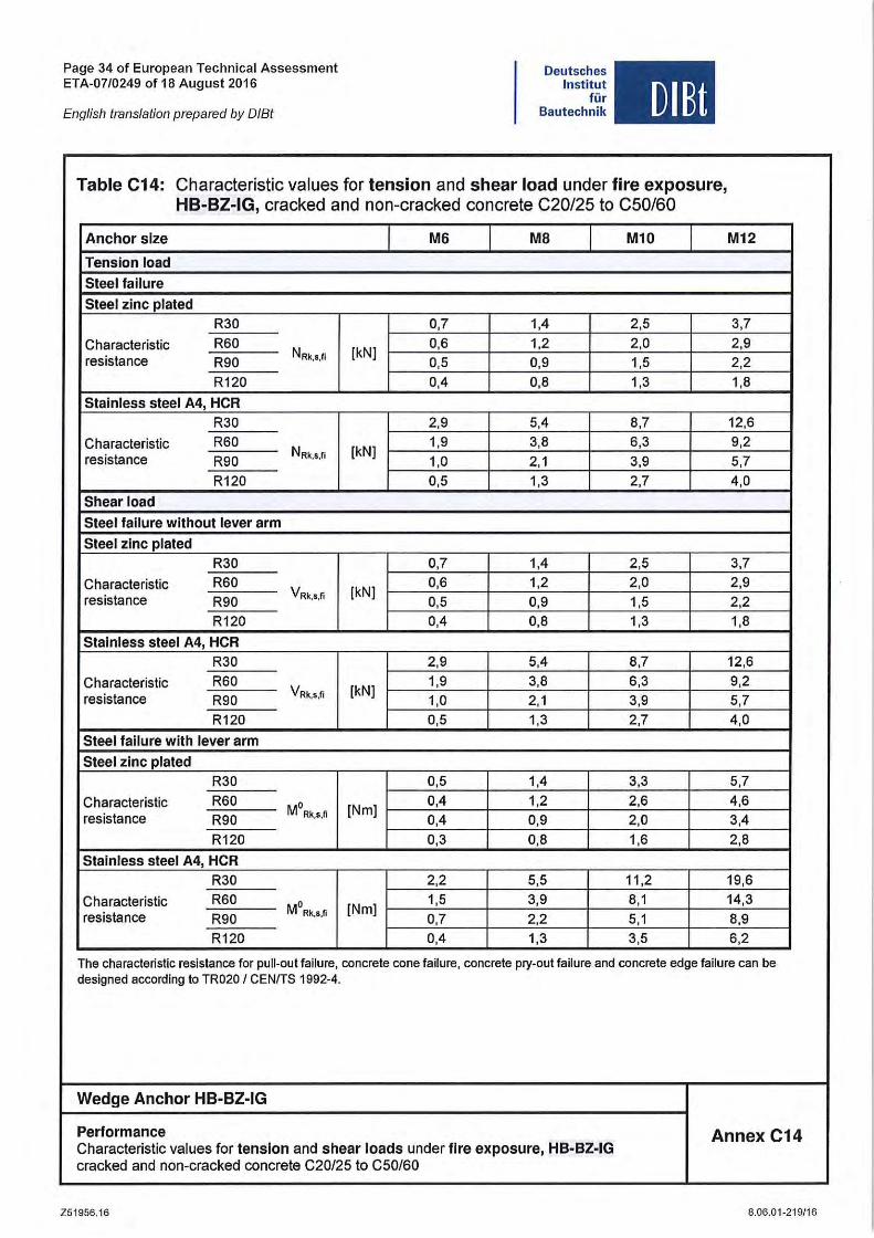
Table C14: Characlerislic values tor tension and shear load under fire exposure, HB-BZ-IG, cracked and non-cracked concrele C20/25 10 C50/60
Anchor slze M6 MB Ml0 M12
Tension load
Steel failure
Steel zinc plated R30 0,7 1,4 2,5 3,7
Characlerislic R60 NRk,l,fi [kN]
0,6 1,2 2,0 2,9 resistance R90 0,5 0,9 1,5 2,2
R120 0,4 0,8 1,3 1,8
Slainiess sleel A4, HCR R30 2,9 5,4 8,7 12,6
Characterislic R60 NRk,s,fi [kN]
1,9 3,8 6,3 9,2 resislance R90 1,0 2,1 3,9 5,7
R120 0,5 1,3 2,7 4,0
Shear load
Steel failure without lever arm
Sleel zinc plaled R30 0,7 1,4 2,5 3,7
Characteristic R60 VRk,s,fi [kN]
0,6 1,2 2,0 2,9 resistance R90 0,5 0,9 1,5 2,2
R120 0,4 0,8 1,3 1,8
Slainiess sleel A4, HCR R30 2,9 5,4 8,7 12,6
Characteristic R60 VRk,S,fi [kN]
1,9 3,8 6,3 9,2 resistance R90 1,0 2,1 3,9 5,7
R120 0,5 1,3 2,7 4,0
Steel fallure wllh lever arm
Steel zinc plaled R30 0,5 1,4 3,3 5,7
Characteristic R60 MO [Nm] 0,4 1,2 2,6 4,6
resistance R90 Rk,s,fi 0,4 0,9 2,0 3,4
R120 0,3 0,8 1,6 2,8
Slainiess sleel A4, HCR R30 2,2 5,5 11,2 19,6
Characteristic R60 MO [Nm] 1,5 3,9 8,1 14,3
resistance R90 Rk,s,fi 0,7 2,2 5,1 8,9 R120 0,4 1,3 3,5 6,2
The characteristie resistance for pUlt-out failure, concrete eone failure, eonerete pry-out failure and conerete edge failure can be designed accor(Ung to TR020 I CENITS 1992-4.
Wedge Anchor HB-BZ-IG
Performance Characleristic values tor tension and shear loads under flre exposure, HB-BZ-IG
Annex C14
cracked and non-cracked concrele C20/25 10 C50/60
Z51956.16 8.06.01-219/16
Page 35 of European Technical Assessment ETA-0710249 of 18 August 2016
English translation prepared by DIBt
Deutsches Institut
tür Bautechnik
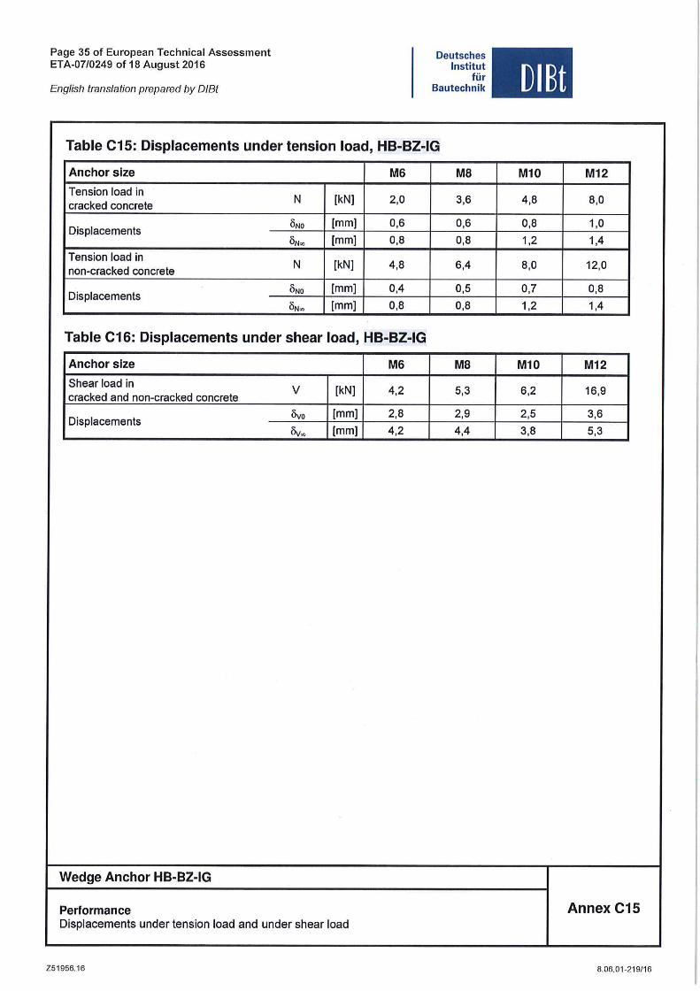
Table C15: Displacements under tension load, HB-BZ-IG
Anchor slze M6 MB
Tension load in N {kN] 2,0 3,6
cracked concrete
Displacemenls IiNO {mm] 0,6 0,6
IiN~ {mm] 0,8 0,8
Tension load in N {kN] 4,8 6,4
non-cracked concrele
Displacemenls IiNO {mm] 0,4 0,5
aN", {mm] 0,8 0,8
Table C16: Displacements under shear load, HB-BZ-IG
Anchor slze M6 MB
Shear load in V {kN] 4,2 5,3 cracked and non-cracked concrele
Displacemenls livo {mm] 2,8 2,9
Iiv. {mm] 4,2 4,4
Wedge Anchor HB-BZ-IG
Performance Displacements under tension load and under shear load
Z51956.16
OIBt
M10 M12
4,8 8,0
0,8 1,0
1,2 1,4
8,0 12,0
0,7 0,8
1,2 1,4
M10 M12
6,2 16,9
2,5 3,6
3,8 5,3
Annex C15
8.06.01-219/16
© 2
016
HA
LFEN
Gm
bH, G
erm
any
appl
ies
also
to
copy
ing
in e
xtra
cts.
B - 1
30 -
E - 0
8/16
PD
F 0
8/16
NOTES REGARDING THIS CATALOGUETechnical and design changes reserved. The information in this publication is based on state-of-the-art technology at the time of publication. We reserve the right to make technical and design changes at any time. HALFEN GmbH shall not accept liability for the accuracy of the information in this publication or for any printing errors.
The Quality Management System of HALFEN GmbH is certified for the locations in Germany, France, the Netherlands, Austria, Poland, Switzerland and the Czech Republic according to DIN EN ISO 9001:2015, Certificate No. QS-281 HH.
Furthermore HALFEN is represented with sales offices and distributors worldwide. Please contact us: www.halfen.com
Austria HALFEN Gesellschaft m.b.H.Leonard-Bernstein-Str. 101220 Wien
Phone: +43 - 1 - 259 6770 E-Mail: [email protected]: www.halfen.at
Fax: +43 - 1 - 259 - 6770 99
Belgium / Luxembourg HALFEN N.V.Borkelstraat 1312900 Schoten
Phone: +32 - 3 - 658 07 20E-Mail: [email protected]: www.halfen.be
Fax: +32 - 3 - 658 15 33
China HALFEN Construction Accessories Distribution Co.Ltd.Room 601 Tower D, Vantone CentreNo. A6 Chao Yang Men Wai StreetChaoyang District Beijing · P.R. China 100020
Phone: +86 - 10 5907 3200E-Mail: [email protected]: www.halfen.cn
Fax: +86 - 10 5907 3218
Czech Republic HALFEN s.r.o.Business Center ŠafránkovaŠafránkova 1238/1155 00 Praha 5
Phone: +420 - 311 - 690 060E-Mail: [email protected]: www.halfen-deha.cz
Fax: +420 - 235 - 314 308
France HALFEN S.A.S.18, rue Goubet75019 Paris
Phone: +33 - 1 - 445231 00E-Mail: [email protected]: www.halfen.fr
Fax: +33 - 1 - 445231 52
Germany HALFEN Vertriebsgesellschaft mbHLiebigstr. 14 40764 Langenfeld
Phone: +49 - 2173 - 970 - 0E-Mail: [email protected]: www.halfen.de
Fax: +49 - 2173 - 970 225
Italy HALFEN S.r.l. Soc. UnipersonaleVia F.lli Bronzetti N° 2824124 Bergamo
Phone: +39 - 035 - 0760711E-Mail: [email protected]: www.halfen.it
Fax: +39 - 035 - 0760799
Netherlands HALFEN b.v.Oostermaat 37623 CS Borne
Phone: +31 - 74-267 14 49E-Mail: [email protected]: www.halfen.nl
Fax: +31 - 74-267 26 59
Norway HALFEN ASPostboks 20804095 Stavanger
Phone: +47 - 51 82 34 00E-Mail: [email protected]: www.halfen.no
Fax: +47 - 51 82 34 01
Poland HALFEN Sp. z o.o.Ul. Obornicka 28760-691 Poznan
Phone: +48 - 61 - 622 14 14E-Mail: [email protected]: www.halfen.pl
Fax: +48 - 61 - 622 14 15
Sweden Halfen ABVädursgatan 5412 50 Göteborg
Phone: +46 - 31 - 98 58 00E-Mail: [email protected]: www.halfen.se
Fax: +46 - 31 - 98 58 01
Switzerland HALFEN Swiss AGHertistrasse 25 8304 Wallisellen
Phone: +41 - 44 - 849 78 78E-Mail: [email protected]: www.halfen.ch
Fax: +41 - 44 - 849 78 79
United Kingdom /Ireland
HALFEN Ltd.A1/A2 Portland CloseHoughton Regis LU5 5AW
Phone: +44 - 1582 - 47 03 00E-Mail: [email protected]: www.halfen.co.uk
Fax: +44 - 1582 - 47 03 04
United States of America HALFEN USA Inc. PO Box 18687 San Antonio TX 78218
Phone: +1 800.423.91 40E-Mail: [email protected]: www.halfenusa.com
Fax: +1 877.683.4910
For countries not listed HALFEN International
HALFEN International GmbHLiebigstr. 14 40764 Langenfeld / Germany
Phone: +49 - 2173 - 970 - 0 E-Mail: [email protected]: www.halfen.com
Fax: +49 - 2173 - 970 - 849
CONTACT HALFEN WORLDWIDE
HALFEN is represented by subsidiaries in the following 14 countries, please contact us: