Haibin Zuo 1, 1 2
13
metals Article Damage Mechanism of Copper Staves in a 3200 m 3 Blast Furnace Haibin Zuo 1, * , Yajie Wang 1 and Xuebin Wang 2 1 State Key Laboratory of Advanced Metallurgy, University of Science and Technology Beijing, Beijing 100083, China; [email protected] 2 Shandong Iron and Steel Co., Ltd. Laiwu Branch, Laiwu 271104, China; [email protected] * Correspondence: [email protected]; Tel.: +86-139-1094-9735 Received: 24 October 2018; Accepted: 8 November 2018; Published: 13 November 2018 Abstract: Copper staves have been widely applied in large blast furnaces especially those whose inner volumes exceed 2000 m 3 due to high cooling capacity. In the past decade, copper staves suffered severe damages in some blast furnaces, which not only shortened their campaign lives, but also caused huge economic losses. In order to make out this phenomenon, the damage mechanism of copper staves was investigated via analyzing the chemical composition, thermal conductivity, metallographic aspects and microstructure in this paper. As a result, the working state was more likely to damage copper staves instead of their materials. At the beginning, the poor quality of the coke and the large bosh angle promoted the development of edge airflow, which intensified the erosion of refractory materials, resulting in the fall-off of slag crusts and damage of cooling water pipes. After repair, the cooling capacity of copper staves still declined, causing the temperature to rise easily; consequently, hydrogen attack happened when the temperature reached 370 ◦ C, which degraded the performance of copper staves. Therefore, copper staves were worn too quickly to form slag crusts, which finally failed under the hydrogen attack and the scouring of the edge airflow at high temperatures. Keywords: blast furnace; copper stave; hydrogen attack; slag crust 1. Introduction In the long-term smelting practice, iron-smelting workers gradually realized that slag crusts are the best furnace lining to protect blast furnaces instead of refractory materials [1–4]. The super cooling capacity of cooling staves is the key to the formation of stable slag crusts [5]. Compared to previously used cast iron cooling staves, copper cooling staves are better thermal conductors because of their good thermal conductivity, thermal shock properties, and heat carrying capacity [6–8]. Therefore, copper staves have become a major development model to decrease the cost of iron making and extend the campaign lives [9–11]. Because they can reduce the thermal stress and further prevent material deformation and cracking of materials [12–15]. Copper staves have been used in many newly built and overhauled large-scale blast furnaces including more than 200 blast furnaces in China and over 45 blast furnaces abroad. The spread of copper staves has not only saved many refractory materials, but also greatly promoted the stable operation of blast furnaces. However, some blast furnaces have experienced major failures in popularizing and applying copper staves since 2010, which caused catastrophic consequences [16]. Three types of copper staves are used in blast furnaces: (1) calendering (including rolling or forging) copper plate welding copper staves; (2) welding copper staves from continuous casting slabs; and (3) buried pipe cast copper staves [17]. Currently, the most widely used is the first type. There are mainly three damaged forms of copper staves: (1) the damage of copper staves in the Metals 2018, 8, 943; doi:10.3390/met8110943 www.mdpi.com/journal/metals
Transcript of Haibin Zuo 1, 1 2

metals
Article
Damage Mechanism of Copper Staves in a 3200 m3
Blast Furnace
Haibin Zuo 1,* , Yajie Wang 1 and Xuebin Wang 2
1 State Key Laboratory of Advanced Metallurgy, University of Science and Technology Beijing, Beijing 100083,China; [email protected]
2 Shandong Iron and Steel Co., Ltd. Laiwu Branch, Laiwu 271104, China; [email protected]* Correspondence: [email protected]; Tel.: +86-139-1094-9735
Received: 24 October 2018; Accepted: 8 November 2018; Published: 13 November 2018�����������������
Abstract: Copper staves have been widely applied in large blast furnaces especially those whoseinner volumes exceed 2000 m3 due to high cooling capacity. In the past decade, copper staves sufferedsevere damages in some blast furnaces, which not only shortened their campaign lives, but alsocaused huge economic losses. In order to make out this phenomenon, the damage mechanismof copper staves was investigated via analyzing the chemical composition, thermal conductivity,metallographic aspects and microstructure in this paper. As a result, the working state was more likelyto damage copper staves instead of their materials. At the beginning, the poor quality of the cokeand the large bosh angle promoted the development of edge airflow, which intensified the erosion ofrefractory materials, resulting in the fall-off of slag crusts and damage of cooling water pipes. Afterrepair, the cooling capacity of copper staves still declined, causing the temperature to rise easily;consequently, hydrogen attack happened when the temperature reached 370 ◦C, which degradedthe performance of copper staves. Therefore, copper staves were worn too quickly to form slagcrusts, which finally failed under the hydrogen attack and the scouring of the edge airflow athigh temperatures.
Keywords: blast furnace; copper stave; hydrogen attack; slag crust
1. Introduction
In the long-term smelting practice, iron-smelting workers gradually realized that slag crusts arethe best furnace lining to protect blast furnaces instead of refractory materials [1–4]. The super coolingcapacity of cooling staves is the key to the formation of stable slag crusts [5]. Compared to previouslyused cast iron cooling staves, copper cooling staves are better thermal conductors because of theirgood thermal conductivity, thermal shock properties, and heat carrying capacity [6–8]. Therefore,copper staves have become a major development model to decrease the cost of iron making and extendthe campaign lives [9–11]. Because they can reduce the thermal stress and further prevent materialdeformation and cracking of materials [12–15]. Copper staves have been used in many newly builtand overhauled large-scale blast furnaces including more than 200 blast furnaces in China and over45 blast furnaces abroad. The spread of copper staves has not only saved many refractory materials,but also greatly promoted the stable operation of blast furnaces. However, some blast furnaces haveexperienced major failures in popularizing and applying copper staves since 2010, which causedcatastrophic consequences [16].
Three types of copper staves are used in blast furnaces: (1) calendering (including rolling orforging) copper plate welding copper staves; (2) welding copper staves from continuous castingslabs; and (3) buried pipe cast copper staves [17]. Currently, the most widely used is the first type.There are mainly three damaged forms of copper staves: (1) the damage of copper staves in the
Metals 2018, 8, 943; doi:10.3390/met8110943 www.mdpi.com/journal/metals

Metals 2018, 8, 943 2 of 13
tuyere area caused by the unreasonable design of the furnace structure; (2) the damage caused by themanufacturing defects; and (3) the large area damage of the local hot surface caused by the “severeshortage of cooling strength”. What is commonly found in blast furnaces is the first two damagedforms. However, the third damaged form occurred frequently recently in China, shown as follows:(1) Copper staves were burnt out in a large area, whose shape was destroyed. (2) The local part ofcopper staves was seriously worn, losing its original shape and weakening its function. (3) Coolingwater pipes were exposed because severe wear occurred at both ends of copper staves. (4) Copperstaves were bent and deformed, which were convex toward the hot surface. To solve these problems,the damage mechanism of the third damaged form is studied in depth in this paper.
2. Materials and Methods
Damaged copper staves were gathered from No. 3 blast furnace of Laiwu Steel, which was3200 m3 in inner volume and put into operation on 16 March 2010. From December 2015, the eighthstory-cooling pipes began to experience damage. Despite remedial measures, such as installing a pointcooler on the damaged part, spraying water and covering the tank outside the shell, multiple coolingpipes in bosh (No. 7 and No. 8 story) and belly (No. 9 story) were damaged one after another in thefollowing half year, especially in the group 35–39.
In order to analyze the damage mechanism of copper staves, five copper columns drilled fromdifferent positions of the damaged stave and the adhesive material on the hot surface of stave werecollected. The chemical composition was detected according to the Chinese standards of GB/T andNACIS/C, respectively. Using the LFA427 laser thermal conductivity meter, the thermal conductivitywas determined according to the method of ASTM E 1461. The metallographic aspects of coppersamples, which were coarsely ground, polished, and then pickled with a solution of ferric chlorideaqueous hydrochloric acid, were observed under a JX-4R metallurgical microscope (PDV, Beijing,China). Using the Quanta FEG 250 scanning electron microscope (FEI, Hillsboro, OR, USA) and energyspectrum analysis, changes in the microstructure and the chemical composition at each location of thecooling stave after service were studied.
3. Results
3.1. Chemical Composition
Table 1 shows the chemical composition of TU2 (An oxygen-free copper, in line with GB/T5231-2001) the material of copper staves that we investigated. Tables 2 and 3 list the chemicalcomposition of damaged copper stave at different sampling point and the harmful element compositionof the adhesive material, respectively. The chemical composition of copper samples was basicallyconsistent with oxygen-free copper TU2 except Zn of No. 5 sample. Zn was also high in the adherentslag, while K, Na, As, P, and S were at normal level compared to common slag. Although Zn cangreatly reduce the thermal conductivity of the copper, its content was not enough to have an impact.Therefore, the chemical composition of the cooling stave was qualified.
Table 1. Chemical composition of TU2 (wt. %).
Si P S Ni Ag As Bi
0.001 0.002 0.004 0.002 – 0.002 0.001Cu + Ag O Sb Fe Pb Sn Zn
99.95 0.003 0.002 0.004 0.004 0.002 0.003

Metals 2018, 8, 943 3 of 13
Table 2. Chemical composition of test samples (wt. %).
Sample Si P S Ni Ag As Bi
1 <0.0005 <0.0005 0.0013 <0.0005 0.0003 <0.0005 <0.000012 <0.0005 <0.0005 0.0014 <0.0005 0.0005 <0.0005 <0.000013 <0.0005 <0.0005 0.0013 <0.0005 0.0008 <0.0005 <0.000014 <0.0005 <0.0005 0.0014 <0.0005 0.0008 <0.0005 <0.000015 <0.0005 <0.0005 0.0012 <0.0005 0.0008 <0.0005 0.00003
Sample Cu + Ag O Sb Fe Pb Sn Zn
1 99.98 0.0005 <0.0001 0.003 0.0002 <0.0001 <0.00052 99.97 0.0001 <0.0001 0.003 0.0002 <0.0001 0.00153 99.96 0.0004 <0.0001 0.002 0.0002 <0.0001 <0.00054 99.96 0.0003 <0.0001 0.006 0.0003 <0.0001 0.00155 99.96 <0.0001 <0.0001 0.002 0.0015 <0.0001 0.013
Table 3. Harmful element composition of the adherent slag (wt. %).
C Mn P S Ti As
2.54 0.21 0.12 0.43 0.18 <0.005Ca K Na Pb SiO2 Zn
12.80 0.54 0.24 0.0026 18.72 0.34
3.2. Thermal Conductivity
The thermal conductivity of copper samples was tested after service via sampling the hotsurface, as shown in Table 4. Under normal circumstances, the thermal conductivity of the copper is340–385 W/(m·K) at room temperature, which decreases gradually with the increase of temperature.Therefore, overheating should be avoided as much as possible.
Table 4. Thermal conductivity of copper samples (W/(m·K)).
Sample Room Temperature 100 ◦C 200 ◦C
1 380.83 358.08 347.972 394.22 372.46 357.483 382.02 359.06 349.264 379.84 362.41 350.605 364.82 354.23 348.46
3.3. Metallographic Aspects
Thermal shock occurred repeatedly on the hot surface during the service of copper staves.As shown in Figure 1, the metallographic structure was observed under optical microscope to study theinfluence of temperature fluctuations on the hot surface. Figure 2 shows the metallographic structureof the pure copper. Compared to the pure copper, the metallographic structure of the copper stave hadlittle change after service as the grain growth did not happen, thus, the performance of copper staveswas stable.

Metals 2018, 8, 943 4 of 13
Figure 1. Metallographic structure of copper staves: (a) amplification factor, 60; (b) amplificationfactor, 150.
Figure 2. Metallographic structure of the pure copper: (a) amplification factor, 60; (b) amplificationfactor, 150.
3.4. Microstructure
Figure 3 shows the microstructure of copper staves observed via scanning electron microscopy.Some tiny cracks (about 40–60 µm in length) distributed on the image of copper staves, which hada tendency to develop further as their ends were tapered. Therefore, these cracks would grow to largercracks if they were stretched or compressed under the force of thermal stress, resulting in rupture andleak of copper staves.
Figure 3. Microstructure of copper staves: (a) Backscatter imaging; (b) Secondary electron imaging.

Metals 2018, 8, 943 5 of 13
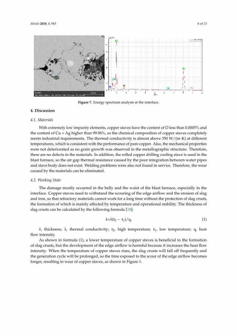
The energy spectrum analysis was used to determine the chemical composition. As shown inFigure 4, there were Cu, O, C, and Si at the crack, while there was no O at the crack-free location,as shown in Figure 5. Figure 6 shows the energy spectrum analysis of the spot-like inclusion, where Si,C, and Cu were found. As the same as Figure 4, C and Si might come from the polishing paste. Figure 7shows the energy spectrum analysis at the interface between copper staves and slag crusts. As a result,copper staves were seriously eroded as Cu, O, C, Si, and Fe were found at the interface.
Figure 4. Energy spectrum analysis at the crack.
Figure 5. Energy spectrum analysis at the crack-free location.
Figure 6. Energy spectrum analysis of the spot-like inclusion.
Metals 2018, 8, 943 6 of 13
Figure 7. Energy spectrum analysis at the interface.
4. Discussion
4.1. Materials
With extremely low impurity elements, copper staves have the content of O less than 0.0005% andthe content of Cu + Ag higher than 99.96%, so the chemical composition of copper staves completelymeets industrial requirements. The thermal conductivity is almost above 350 W/(m·K) at differenttemperatures, which is consistent with the performance of pure copper. Also, the mechanical propertieswere not deteriorated as no grain growth was observed in the metallographic structure. Therefore,there are no defects in the materials. In addition, the rolled copper drilling cooling stave is used in theblast furnace, so the air gap thermal resistance caused by the poor integration between water pipesand stave body does not exist. Welding problems were also not found in service. Therefore, the wearcaused by the materials can be eliminated.
4.2. Working State
The damage mostly occurred in the belly and the waist of the blast furnace, especially in theinterface. Copper staves need to withstand the scouring of the edge airflow and the erosion of slagand iron, so that refractory materials cannot work for a long time without the protection of slag crusts,the formation of which is mainly affected by temperature and operational stability. The thickness ofslag crusts can be calculated by the following formula [18]:
δ=λ(t2 − t1)/q, (1)
δ, thickness; λ, thermal conductivity; t2, high temperature; t1, low temperature; q, heatflow intensity.
As shown in formula (1), a lower temperature of copper staves is beneficial to the formationof slag crusts, but the development of the edge airflow is harmful because it increases the heat flowintensity. When the temperature of copper staves rises, the slag crusts will fall off frequently andthe generation cycle will be prolonged, so the time exposed to the scour of the edge airflow becomeslonger, resulting in wear of copper staves, as shown in Figure 8.

Metals 2018, 8, 943 7 of 13
Figure 8. Changes in temperature under normal and abnormal conditions.
Figure 9 shows the changes in temperature after copper staves were damaged. The coolingcapacity decreased due to the loss of cooling water after cooling water pipes damaged, therefore,the temperature of copper staves rose and fluctuated rapidly [19]. The average temperature of the37th and 38th groups exceeded 550 ◦C and 400 ◦C in the later period, much higher than the allowableworking temperature (180 ◦C) in the long term. Consequently, slag crusts were difficult to form at thistemperature. Also, the hot surface became smooth because of the wear of copper staves, which wasalso not conductive to the stability of slag crusts.
Figure 9. Changes in temperature after copper staves were damaged.
The blast furnace utilization coefficient was 2.5–2.7 t/(m3·d) for a long time, indicating the highworking strength, thus, the amount of gas and the gas flow rate were both large in the furnace. The edgeairflow would develop when the raw materials were bad. It is mainly the coke that determined thepermeability of the charge. The average ash content and sulfur content of coke for the blast furnacewere 12.77% and 0.818%, respectively, which were all at a high level in China. In addition, the indicatorsof coke quality such as M40, M10, CRI, and CSR were also poor compared to the same size blastfurnaces in China. Poor coke quality would degrade the permeability of the burden, resulting in thedevelopment of edge airflow. A large amount of coke breeze was generated during the productiondue to the low thermal intensity, which had a strong scouring effect on the refractory materials andstave body under the condition of high-speed airflow.
With the development of thin-walled blast furnaces, the furnace type has undergone tremendouschanges, resulting in the disappearance of the difference between the design furnace type and the

Metals 2018, 8, 943 8 of 13
working furnace type. Therefore, many of problems occur with the continuation of the previous boshangle for the thin-walled blast furnaces, especially for use of copper staves. One of the problems is thatthe bosh angle is too large as the abrasion of the refractory bricks increases with the increase of thebosh angle [20]. The bosh angle is greater than 78 deg for the blast furnace in Laiwu Steel, however,it is 72–74 deg for the advanced blast furnaces in the world, which have long campaign lives and lowfuel ratios. Therefore, the large bosh angle creates conditions for the development of the edge airflow.Figure 10 shows the radial distribution of the airflow velocity under different bosh angles simulatedby Fluent 14.5 (ANSYS, Pittsburgh, PA, USA).
Figure 10. Radial distribution of the airflow velocity (m/s) under different bosh angles.
As shown in Figure 10, the velocity of the edge airflow increased as the bosh angle increased,especially in the boundary between the belly and the waist, where the light-colored area increased,

Metals 2018, 8, 943 9 of 13
and the color became lighter, indicating the increase of the velocity of the edge airflow. Figure 11 showsthe velocity distribution of the edge airflow under different bosh angles. The velocity of the edgeairflow increased exponentially as the bosh angle increased from 74 deg to 79 deg, which intensifiedthe wear of copper cooling stave.
Figure 11. Radial distribution of edge airflow velocity under different bosh angles.
4.3. Damage Process
The damage of copper staves has gone through the following stages based on above analysis:The first stage was the erosion and wear of refractory bricks. A certain thickness of refractory
bricks was embedded in the dovetail groove of the hot surface. When the refractory bricks wereintact, copper staves were well protected, and the temperature and thermal stress were very low atthis time, therefore, the refractory bricks resisted the initial erosion and wear. Figure 12 shows thetemperature distribution of refractory bricks under different thicknesses simulated by ANSYS 14.5(ANSYS, Pittsburgh, PA, USA).
Figure 12. Cont.

Metals 2018, 8, 943 10 of 13
Figure 12. Temperature (◦C) distribution of refractory bricks under different thicknesses.
The increase in the thickness led to an increase in temperature, because it increased the totalthermal resistance, leading to the decrease in heat transfer capacity. The highest temperature appearedin the lowermost corner position, which was prone to damage. The slag crust was difficult to formwhen the temperature exceeded 800 ◦C, resulting in the ablation and thinning of refractory bricks.Figure 13 shows the stress distribution of refractory bricks under different thicknesses. The maximumstress underwent a process of decreasing first and then increasing as the thickness of refractory bricksincreased. Under the action of high thermal stress and high temperature, the refractory bricks werecontinuously eroded by the liquid slag and iron, and scoured by the high-temperature airflow carryinga large number of coke breeze without the protection of slag crusts [21].
Figure 13. Cont.

Metals 2018, 8, 943 11 of 13
Figure 13. Stress (Pa) distribution of refractory bricks under different thicknesses.
The second stage was the damage of copper staves after the refractory bricks disappeared.As a result, copper staves were directly exposed to high-speed airflow, but the maximum temperaturewould not exceed 300 ◦C as long as the cooling capacity was sufficient. Figure 14 shows thethermocouple temperature under different working conditions. The stave body would not be ablatedeven if there was no protection of refractory bricks. The major damage was due to the scouring of thehigh-temperature airflow carrying the coke breeze. As the wear of copper staves intensified, it wasforced to break the water and block the water pipe when a part was worn to the cooling water pipe.The reduction in cooling capacity and the increase in temperature of copper staves were inevitableresults regardless of the remedy.
Figure 14. Thermocouple temperature under different working conditions (Working conditions 1–3:flue gas temperature, 1000 ◦C, 1100 ◦C, and 1200 ◦C, respectively; cooling water flow rate, 16 t/h.Working conditions 4–6: flue gas temperature, 1200 ◦C; cooling water flow, 12 t/h, 8 t/h, and 4 t/h,respectively. Thermocouples 1–3: thermocouple temperature of 10 mm from the hot surface at theupper, middle and lower parts of copper staves.).

Metals 2018, 8, 943 12 of 13
The third stage was the hydrogen attack after the temperature rose because of the damage ofcooling water pipes [16]. The contents of O and C were high at the crack and interface. Generally,the solid solution of oxygen in the copper is very low, but there is a strong affinity between theoxygen and copper; therefore, excess oxygen and copper will form Cu2O and distribute on the grainboundaries or in the dendrite network, and the tendency increases as the temperature rises. The harmof hydrogen on oxygen-containing copper is related to the temperature. Hydrogen does not harmthe oxygen-containing copper at 150 ◦C because the water vapor is in the condensed state. Undera hydrogen atmosphere, the oxygen-containing copper will not crack within 10 years at 150 ◦C, but itwill crack after no more than 1.5 years at 200 ◦C or 70 hours at 400 ◦C [22]. Ordinary copper (oxygencontent, 0.02–0.1%) is prone to have a hydrogen attack in a reducing medium with a temperaturegreater than 370 ◦C. Unlike ordinary copper, oxygen-free copper (oxygen content, ≤0.002%) can beprocessed and used under reducing atmosphere conditions, but it is also likely to have a hydrogenattack. The occurrence of hydrogen attack must meet the following conditions at the same time: the firstis the reducing atmosphere, which is available in the blast furnace, the second is the oxygen content,and the third is the temperature of copper staves. The temperature of the thermocouple installed at thedamaged copper cooling stave exceeded 400 ◦C for a long time according to the monitoring results,which created conditions for cracking and damage caused by hydrogen attack.
The final stage was the wear of copper staves under high temperatures. First, the hot surface ofcopper staves damaged severely due to hydrogen attack; meanwhile, the poor raw materials and largebosh angle created conditions for the development of edge airflow. Therefore, the high-speed andhigh-temperature airflow carrying a large amount of coke breeze intensified the wear of copper staves.Thus, the surface of copper staves was worn smooth, and the temperature rose rapidly due to thedamage of cooling pipes. Consequently, the stable slag crusts were difficult to form, leading to the lossof protection to copper staves. Finally, the temperature of the hot surface was continuously increased,resulting in a decrease in the hardness and wear resistance of the copper, thus, copper staves werecompletely damaged under high-speed wear.
5. Conclusions
The damage process of copper staves is as follows:
(1) The poor raw materials, especially poor coke quality, and the large bosh angle caused thedevelopment of the edge airflow to maintain the high smelting strength. The high-temperatureand high-speed airflow carrying the coke breeze generated by the deterioration had a strongscouring effect on the refractory bricks, which were continuously eroded by the slag, iron,and airflow under thermal stress and high temperature.
(2) Slag crusts were difficult to be stable due to the increase of temperature, causing damage to thewater pipes. The cooling strength inevitably declined after remedy, resulting in an increase in thetemperature of copper staves and a decrease in the capacity to form slag crusts.
(3) The hydrogen attack happened under the reducing atmosphere when the temperature was greaterthan 370 ◦C, leading to the development of cracks at the hot surface. As a result, the performanceof copper staves such as the hardness at the high temperature and the wear resistance decreased.Copper staves were quickly worn to form a smooth surface under continuous scouring of theedge airflow, thus, it became more difficult to form slag crusts. Under the hydrogen attack andthe scouring of the edge airflow at the high temperature, copper staves finally failed.
Author Contributions: Conceptualization, H.Z.; Data curation, H.Z.; Resources, X.W.; Writing—original draft,Y.W.; Writing—review and editing, Y.W.
Funding: This research was funded by National Key Research and Development Program (No. 2016YFB0601304).
Conflicts of Interest: The authors declare no conflict of interest.

Metals 2018, 8, 943 13 of 13
References
1. Frolova, I.B.; Minkin, V.M.; Frolov, V.A.; Yukhimenko, V.I. The slag crust in high-temperature iron oresmelting. Refract. Ind. Ceram. 1976, 17, 429–432. [CrossRef]
2. Zamoskovtsev, D.E.; Lednov, A.Y.; Kishchuk, V.D.; Chaplouskii, A.A. Ultrasonic diagnosis in control of theslag crust. Metallurgist 1997, 41, 436. [CrossRef]
3. An, J.Q.; Zhang, J.L.; Wu, M.; She, J.H.; Terano, T. Soft-sensing method for slag-crust state of blast furnacebased on two-dimensional decision fusion. Neurocomputing 2018, 315, 405–411. [CrossRef]
4. Jiao, K.X.; Zhang, J.L.; Liu, Z.J.; Liu, F.; Liang, L.S. Formation mechanism of the graphite-rich protective layerin blast furnace hearths. Int. J. Miner. Metall. Mater. 2016, 23, 16–24. [CrossRef]
5. Zhang, H.; Jiao, K.X.; Zhang, J.L.; Chen, Y.B. A new method for evaluating cooling capacity of blast furnacecooling stave. Ironmak. Steelmak. 2018. [CrossRef]
6. Mohanty, T.R.; Sahoo, S.K.; Moharana, M.K. Computational modeling of blast furnace save cooler based onsteady state heat transfer analysis. Procedia Eng. 2015, 127, 940–946. [CrossRef]
7. Xu, X.; Wu, L.J.; Lu, Z.A. Performance optimization criterion of blast furnace stave. Int. J. Heat Mass Transf.2017, 105, 102–108. [CrossRef]
8. Wu, L.J.; Zhou, W.G.; Su, Y.L.; Li, X.J. Experimental and operational thermal studies on blast furnace caststeel staves. Ironmak. Steelmak. 2008, 35, 179–182. [CrossRef]
9. Yeh, C.P.; Ho, C.K.; Yang, R.J. Conjugate heat transfer analysis of copper staves and sensor bars in a blastfurnace for various refractory lining thickness. Int. Commun. Heat Mass Transf. 2012, 39, 58–65. [CrossRef]
10. Balamurugan, S.; Shunmugasundaram, R.; Patra, M.; Pani, S.; Dutta, M. Evaluation of copper stave remnantthickness in blast furnace using ultrasonic method. ISIJ Int. 2015, 55, 605–610. [CrossRef]
11. Liu, Z.J.; Zhang, J.L.; Zuo, H.B.; Yang, T.J. Recent progress on long service life design of Chinese blast furnacehearth. ISIJ Int. 2012, 52, 1713–1723. [CrossRef]
12. Chen, W.C.; Cheng, W.T. Numerical simulation on forced convective heat transfer of titanium dioxide/waternanofluid in the cooling stave of blast furnace. Int. Commun. Heat Mass Transf. 2016, 71, 208–215. [CrossRef]
13. Liu, Q.; Cheng, S.S. Heat transfer and thermal deformation analyses of a copper stave used in the belly andlower shaft area of a blast furnace. Inter. J. Therm. Sci. 2016, 100, 202–212. [CrossRef]
14. Wu, T.; Cheng, S.S. Model of forming-accretion on blast furnace copper stave and industrial application.J. Iron Steel Res. Int. 2012, 19, 1–5. [CrossRef]
15. Xie, N.Q.; Cheng, S.S. Analysis of effect of gas temperature on cooling stave of blast furnace. J. Iron SteelRes. Int. 2010, 17, 1–6. [CrossRef]
16. Deng, Y.; Jiao, K.X.; Wu, Q.C.; Zhang, J.L.; Yang, T.J. Damage mechanism of copper stave used in blastfurnace. Ironmak. Steelmak. 2017. [CrossRef]
17. Wang, X.L. Iron and Steel Metallurgy (Ironmaking), 3rd ed.; Metallurgical Industry Press: Beijing, China, 2013;p. 391. ISBN 978-7-5024-6130-0.
18. Hua, J.S.; Zhu, J.; Li, X.M.; Ma, Y.P. Principles of Transfer in Metallurgy, 1st ed.; Northwestern PolytechnicalUniversity Press: Xi’an, China, 2005; p. 88. ISBN 7-5612-1904-0.
19. Li, Y.L.; Cheng, S.S. Cooling capacity recovery of copper stave based on heat transfer. J. Iron Steel Res. 2012,24, 5. [CrossRef]
20. Zhang, J.L.; Chen, Y.X.; Fan, Z.Y.; Hu, Z.W.; Yang, T.J.; Tatsuro, A. Influence of profile of blast furnace onmotion and stress of burden by 3D-DEM. J. Iron Steel Res. Int. 2011, 18, 1–6. [CrossRef]
21. Li, F.G.; Zhang, J.L. Stress distribution law and adherent dross stability of the copper cooling stave withvariable slag coating thickness. Chin. J. Eng. 2017, 39, 389–398. [CrossRef]
22. Zhong, W.J. Practical Manual for Processing Technology of Copper, 1st ed.; Metallurgical Industry Press: Beijing,China, 2007; p. 78. ISBN 978-7-5024-4100-5.
© 2018 by the authors. Licensee MDPI, Basel, Switzerland. This article is an open accessarticle distributed under the terms and conditions of the Creative Commons Attribution(CC BY) license (http://creativecommons.org/licenses/by/4.0/).