H.323 Tutorial - KAMBING.ui.ac.idkambing.ui.ac.id/.../physical/voip/tutorial/tutorial-h323.pdf ·...
23
© 2000 Realsoft Corporation http://www.realsoft-corp.com/ January 12, 2000 Abstract: This document summarizes the H.323 (H.225, H.245) Recommendation into an understandable tutorial. Much of the material is derived from the Recommendations directly. The salient features of the Recommendations are presented here; for detailed information, refer to the Recommendations directly. This document is provided for instructional purposes only. H.323 Tutorial
Transcript of H.323 Tutorial - KAMBING.ui.ac.idkambing.ui.ac.id/.../physical/voip/tutorial/tutorial-h323.pdf ·...

© 2000 Realsoft Corporation http://www.realsoft-corp.com/
January 12, 2000 Abstract: This document summarizes the H.323 (H.225, H.245)
Recommendation into an understandable tutorial. Much of the material is derived from the Recommendations directly. The salient features of the Recommendations are presented here; for detailed information, refer to the Recommendations directly. This document is provided for instructional purposes only.
H.323 Tutorial


Table of Contents
1 H.323 OVERVIEW ........................................................................................ 1
2 H.323 ZONE.................................................................................................. 1
2.1 Terminal............................................................................................................. 2
2.2 Gateway ............................................................................................................. 2
2.3 Gatekeeper......................................................................................................... 3
2.4 MCU................................................................................................................... 3
3 H.225 ............................................................................................................ 3
3.1 RAS signaling..................................................................................................... 3 3.1.1 Gatekeeper discovery................................................................................... 5 3.1.2 Endpoint registration.................................................................................... 5 3.1.3 Endpoint location......................................................................................... 6 3.1.4 Admissions, bandwidth change, status and disengage................................... 6 3.1.5 RAS Signaling Channel ............................................................................... 7
3.2 H.225 call signaling............................................................................................ 7 3.2.1 Setup ........................................................................................................... 8 3.2.2 Facility ........................................................................................................ 8 3.2.3 Alerting ....................................................................................................... 8 3.2.4 Call Proceeding............................................................................................ 8 3.2.5 Connect ....................................................................................................... 8 3.2.6 Status........................................................................................................... 8 3.2.7 Status Inquiry............................................................................................... 8 3.2.8 Release Complete ........................................................................................ 9 3.2.9 Call Signaling Channel ................................................................................ 9
3.3 H.225 layer......................................................................................................... 9 3.3.1 Use of RTP/RTCP ....................................................................................... 9
4 H.245 ............................................................................................................ 9
4.1 Master/slave determination............................................................................. 10
4.2 Capabilities Exchange ..................................................................................... 10
4.3 Logical Channel Signaling............................................................................... 10

4.4 Mode Request .................................................................................................. 10
4.5 H.245 Control Channel.................................................................................... 11
5 H.323 CALL WALKTHROUGH .................................................................. 11
5.1 Phase 0: RAS ................................................................................................... 11
5.2 Phase A: Call setup.......................................................................................... 11 5.2.1 Basic call setup - Neither endpoint registered with Gatekeeper................... 11 5.2.2 Both endpoints registered, both Gatekeepers routing.................................. 12
5.3 Phase B: Initial communication and capability exchange.............................. 13
5.4 Phase C: Establishment of audiovisual communication................................. 14
5.5 Phase D: Call services...................................................................................... 14
5.6 Phase E: Call termination ............................................................................... 14 5.6.1 Call clearing without a Gatekeeper............................................................. 14 5.6.2 Call clearing with a Gatekeeper.................................................................. 15 5.6.3 Call clearing by Gatekeeper ....................................................................... 15
5.7 Summary.......................................................................................................... 16 5.7.1 Channels .................................................................................................... 18
6 AUDIO CODECS ........................................................................................ 18
7 VIDEO CODECS......................................................................................... 18
8 DATA CAPABILITY.................................................................................... 19
9 ABBREVIATIONS ...................................................................................... 19

1
Realsoft Corporation is a leading provider of H.323 protocol stack software. This software has been used to build IP telephony gateways, which are H.323 compliant, promoting interoperability and open standards.
1 H.323 Overview H.323 is an ITU Recommendation describing the protocols involved in making a call with multimedia capabilities over a packet-based network without guaranteed QoS. H.323 consists of an umbrella set of recommendations, including:
• H.225 • H.245 • Audio codecs • Video codecs • Data capability
The following diagram shows the components of an H.323 protocol stack:
Audio App Video App A/V Control System Control Data App G.7xx H.26x
RTP RTCP
H.225 RAS Control
H.225 Call Control
H.245
Unreliable transport Reliable transport Network layer
Link layer
T.12x
Physical layer
Figure 1 - H.323 layers (gray areas indicate required components)
Note that the network layers are not specified by the Recommendation. Any packet-based network will suffice.
2 H.323 Zone H.323 defines several entity types that work together to form a “Zone”, all under the control of a single gatekeeper. A Zone is the collection of all Terminals (Tx), Gateways (GW), and Multipoint Control Units (MCUs) managed by a single Gatekeeper (GK). A Zone includes at least one terminal, and may or may not include Gateways or MCUs. A Zone must have exactly one Gatekeeper. Otherwise a collection of entities is not considered a valid Zone, although that is not a requirement for operability. A Zone may be independent of network topology and may be comprised of multiple network segments, which are connected using routers (R) or other devices. See Figure 2 for a sample Zone configuration.

2
T1
T2
GK
T3
GW
R R
T4 T5
MCU
Zone
Figure 2 - H.323 zone
2.1 Terminal Terminals are single endpoints used to communicate through the transmission of information streams, as specified in H.323.
2.2 Gateway In general, the purpose of the Gateway is to interface between a packet-based network endpoint to a traditional switched circuit network (SCN) endpoint, and the reverse, in a transparent fashion. The Gateway provides the appropriate translation between transmission formats and between communications procedures. The Gateway also performs call setup and clearing on both the network side and the SCN side. Translation between video, audio, and data formats may also be performed in the Gateway. Below is a picture of how Gateways interact in different networks:
PBX IP Network
PSTN
Gateway
Gateway
PSTN
Gateway
Terminal
Terminal
PSTN
Terminal
Figure 3 - Gateway interfacing with different networks

3
2.3 Gatekeeper The Gatekeeper provides call control services to the H.323 endpoints. More than one Gatekeeper may be present and communicate with each other in an unspecified fashion. The Gatekeeper is logically separate from the endpoints; however, its physical implementation may coexist with a terminal, MCU Gateway, or other device. When it is present in a system, the Gatekeeper provides the following services:
• Address translation - The Gatekeeper translates between alias address to transport address.
• Admissions control - The Gatekeeper authorizes network access. • Bandwidth control - The Gatekeeper performs bandwidth control for bandwidth
requests. • Zone management - The Gatekeeper provides the above functions for terminals,
MCUs, and Gateways, which have registered with it. The Gatekeeper can optionally also perform other functions such as:
• Call control signaling - The Gatekeeper may choose to complete the call signaling with the endpoints, and may process the call signaling itself. Alternatively, the Gatekeeper may direct the endpoints to connect the Call Signaling Channel directly to each other (see section 3.2.9).
• Call authorization - The Gatekeeper may reject calls due to authorization failure. • Bandwidth management - The Gatekeeper may reject calls from a terminal due to
bandwidth management criteria. • Call management - The Gatekeeper may maintain call status for endpoints. • Directory services - The Gatekeeper may provide some directory information to
route calls.
2.4 MCU The MCU is an endpoint, which provides support for multipoint conferences.
3 H.225 H.225 defines three aspects of a multimedia call: RAS signaling, H.225 call signaling, and the H.225 layer. This section summarizes H.225 functions.
3.1 RAS signaling RAS signaling messages perform registration, admissions, bandwidth changes, status, and disengage procedures between endpoints and Gatekeepers (if Gatekeepers are used). The types of messages RAS includes are:
• Gatekeeper discovery • Endpoint registration • Endpoint location • Admissions, bandwidth change, status and disengage

4
Below is a table of all RAS messages and their relation to endpoint type:
RAS Message Message
Name
Endpoint (Tx)
Endpoint (Rx)
Gatekeeper (Tx)
Gatekeeper (Rx)
GRQ Gatekeeper Request O M
GCF Gatekeeper Confirm O M
GRJ Gatekeeper Reject O M
RRQ Registration Request M M
RCF Registration Confirm
M M
RRJ Registration Reject M M
URQ Unregistration Request
O M O M
UCF Unregistration Confirm
M O M O
URJ Unregistration Reject
O O M O
ARQ Admissions Request M M
ACF Admissions Confirm M M
ARJ Admissions Reject M M
BRQ Bandwidth Request M M O M
BCF Bandwidth Confirm M (Note 1) M M O
BRJ Bandwidth Reject M M M O
IRQ Information Request M M
IRR Information Response
M M
IACK Information request Acknowledgement
O CM
INAK Information request Negative Acknowledgement
O CM
DRQ Disengage Request M M O M
DCF Disengage Confirm M M M M
DRJ Disengage Reject M (Note 2) M M M
LRQ Location Request O O M
LCF Location Confirm O M O
LRJ Location Reject O M O
NSM Non Standard Message
O O O O
XRS Message Not Understood
M M M M
RIP Request In Progress CM M CM M
RAI Resource Availability Indication
O M
RAC Resource Availability Confirmation
O M
M Mandatory, O Optional, F Forbidden, CM Conditionally Mandatory, blank "Not Applicable". NOTE 1 – If a gatekeeper sends a BRQ requesting a lower rate, the endpoint shall reply with BCF if the lower rate is supported, otherwise with BRJ. If a gatekeeper sends a BRQ requesting a higher rate, the endpoint may reply with BCF or BRJ. NOTE 2 – Terminal shall not send DRJ while on a call in response to DRQ from a gatekeeper.
Figure 4 - Table of RAS messages supported

5
These messages are carried out on the RAS Signaling Channel.
3.1.1 Gatekeeper discovery Gatekeeper discovery is the process an endpoint uses to determine which Gatekeeper to register with. An endpoint sends a Gatekeeper Request message (GRQ). One or more Gatekeepers may respond with the Gatekeeper Confirmation message (GCF). If a Gatekeeper does not want the endpoint to register with it, it returns Gatekeeper Reject (GRJ). See Figure 5 for a ladder diagram of this exchange.
Endpoint Gatekeeper
GRQ
GCF/GRJ
Figure 5 - Gatekeeper autodiscovery
3.1.2 Endpoint registration Registration is the process by which an endpoint joins a Zone, and informs the Gatekeeper of its Transport Address and alias addresses. Endpoints register with the Gatekeeper identified through the discovery process. Registration occurs before any calls are attempted and may occur periodically as necessary. A Gatekeeper or MCU may register multiple Transport Addresses. An endpoint sends a Registration Request (RRQ) to a discovered Gatekeeper’s RAS Channel Transport Address. The Gatekeeper responds either with a Registration Confirmation (RCF) or a Registration Reject (RRJ). An endpoint can only register with a single Gatekeeper. The RRQ may be repeated periodically as needed. An endpoint can cancel its registration by sending an Unregister Request (URQ) message to the Gatekeeper. The Gatekeeper responds with an Unregister Confirmation (UCF) message or Unregister Reject (URJ) message. This allows endpoints to change the alias address associated with its Transport Address, or vice versa. See Figure 6 for a ladder diagram of this exchange.

6
Endpoint Gatekeeper
RRQ
RCF or RRJ
URQ
UCF/URJ
URQ
UCF
Endpoint initiated Unregister Request
Gatekeeper initiatedUnregister Request
Figure 6 - Endpoint registration
3.1.3 Endpoint location An endpoint or Gatekeeper or Gatekeeper, which has an alias address for an endpoint and would like to determine its contact information, may issue a Location Request (LRQ) message. The Gatekeeper with which the requested endpoint is registered responds with the Location Confirmation (LCF) message, containing the contact information of the endpoint or the endpoint’s Gatekeeper. Contact information includes the Call Signaling Channel and the RAS Channel addresses to be used to reach the endpoint. Gatekeepers with which the request endpoint is not registered return Location Reject (LRJ).
3.1.4 Admissions, bandwidth change, status and disengage The RAS Channel is also used for the transmission of admissions, bandwidth change, status, and disengage messages. These messages take place between an endpoint and a Gatekeeper and are used to provide admissions control and bandwidth management functions. The Admissions Request (ARQ) message specifies the requested call bandwidth. The Gatekeeper may grant or reduce the bandwidth in the Admissions Confirm (ACF) message. Or the Gatekeeper can reject the ARQ with an Admissions Reject (ARJ) message.

7
An endpoint or the Gatekeeper can attempt to modify the call bandwidth during a call using the Bandwidth Changed Request (BRQ) message. The Gatekeeper or endpoint either agrees with the BRQ by sending a Bandwidth Confirm (BCF) message or disagrees by sending a Bandwidth Reject (BRJ) message. An endpoint or the Gatekeeper can attempt to disengage during a call by using the Disengage Request (DRQ) message. If sent from an endpoint to a Gatekeeper, the DRQ informs the Gatekeeper that an endpoint is being dropped. If sent from a Gatekeeper to an endpoint, the DRQ forces a call to be dropped. The receiving party must reply with a Disengage Confirm (DCF) message if the endpoint is registered with the Gatekeeper, otherwise a Disengage Reject (DRJ) is sent by the Gatekeeper.
3.1.5 RAS Signaling Channel The RAS Signaling Channel is independent from the Call Signaling Channel and the H.245 Control Channel. In network environments that do not have a Gatekeeper, the RAS Signaling Channel is not used. In network environments, which contain a Gatekeeper (a Zone), the RAS Signaling Channel is opened between the endpoint and the Gatekeeper. That RAS Signaling Channel is opened prior to the establishment of any other channels between H.323 endpoints. It is used to carry messages used for Gatekeeper discovery and endpoint registration processes, which associate an endpoint’s alias address with its Call Signaling Channel Transport Address. The RAS Channel is an unreliable channel.
3.2 H.225 call signaling The call signaling function is used to establish a connection between two H.323 endpoints. The call signaling messages used are based on Q.931 call control messages. The following messages are mandatory and comprise the critical call signaling functionality:
Messages Transmit (M, F, O, CM)a)
Receive and act on (M, F, Ob), CM)
Call establishment messages
Alerting M M
Call Proceeding O CMc)
Connect M M
Setup M M
Call Clearing messages
Release Complete Md) M
Miscellaneous messages
Status Me) M
Status Inquiry O M
Q.932/H.450 messages
Facility M M

8
Messages Transmit (M, F, O, CM)a)
Receive and act on (M, F, Ob), CM)
Call establishment messages
a) M Mandatory, F Forbidden, O Optional, CM Conditionally Mandatory. Something is CM if it is required once an option is supported. b) Note that STATUS shall not be sent in response to a message listed here as "O"; the receiver shall simply ignore the message if it
does not support it. c) Terminals intended to use gateways shall receive and act on CALL PROCEEDING. d) Release Complete is required for any situation in which the H.225.0 reliable call signalling channel is open. If this cannel is not
open. H.245 session end may be used to terminate the conference. e) The endpoint shall respond to an unknown message with a STATUS message; response to STATUS INQUIRY is also mandatory.
However, an endpoint is not required to send STATUS INQUIRY. As a practical matter, the endpoint should be able to understand a STATUS message received in response to a message sent that was not known to the receiver
Figure 7 - H.225 call signaling messages
These messages are carried out on the Call Signaling Channel.
3.2.1 Setup This message is sent by a calling H.323 entity to indicate its desire to set up a connection to the called entity. (See section 3.2.5 for information on Connect.)
3.2.2 Facility The Facility message is used to provide information on where a call should be directed, or for an endpoint to indicate that the incoming call must go through a Gatekeeper.
3.2.3 Alerting This message may be sent by the called user to indicate that called user alerting has been initiated.
3.2.4 Call Proceeding This message may be sent by the called user to indicate that requested call establishment has been initiated and no more call establishment information will be accepted.
3.2.5 Connect This message is sent by the called entity to the calling entity to indicate acceptance of the call by the called entity. (See section 3.2.8 for information on Release Complete.
3.2.6 Status The Status message is used to respond to an unknown call signaling message or to a Status Inquiry message.
3.2.7 Status Inquiry The Status Inquiry message can by used to request call status.

9
3.2.8 Release Complete This message is sent by a terminal to indicate release of the call.
3.2.9 Call Signaling Channel The Call Signaling Channel is independent from the RAS Channel and the H.245 Control Channel. The Call Signaling Channel is opened prior to the establishment of the H.245 Channel and any other logical channels between H.3423 endpoints. In systems that do not have a Gatekeeper, the Call Signaling Channel is opened between the two endpoints involved in the call. In systems which contain a Gatekeeper, the initial admission message exchange takes place between the calling endpoint and the Gatekeeper using the Gatekeeper’s RAS Channel. Within the initial admissions message exchange, the Gatekeeper indicates in the ACF message whether to send the call signaling directly to the other endpoint or to route it through the Gatekeeper. The Call Signaling Channel is opened between the endpoint and the Gatekeeper or between the endpoints themselves as chosen by the Gatekeeper. The Call Signaling Channel is used to carry H.225 call control messages. The Call Signaling channel is a reliable channel.
3.3 H.225 layer The H.225 layer formats the transmitted video, audio, data and control streams into messages for output to the network interface and retrieves the received video, audio, data, and control streams from messages, which have been input from the network interface. In addition, it performs logical framing, sequence numbering, error detection and error correction as appropriate to each media type.
3.3.1 Use of RTP/RTCP Using H.245 signaling, audio and video channels may be established if the terminal supports this capability. Since audio and video streams are real-time experiences, these channels must use and follow RTP Version 2.
4 H.245 The H.245 control function carries end-to-end control messages governing H.323 operation. H.245 specifies a number of independent protocol entities which support endpoint-to-endpoint signaling, including:
• Master/slave determination • Capabilities Exchange • Logical Channel Signaling • Bidirectional Logical Channel Signaling • Close Logical Channel Signaling • Mode Request • Round Trip Delay Determination • Maintenance Loop Signaling
10
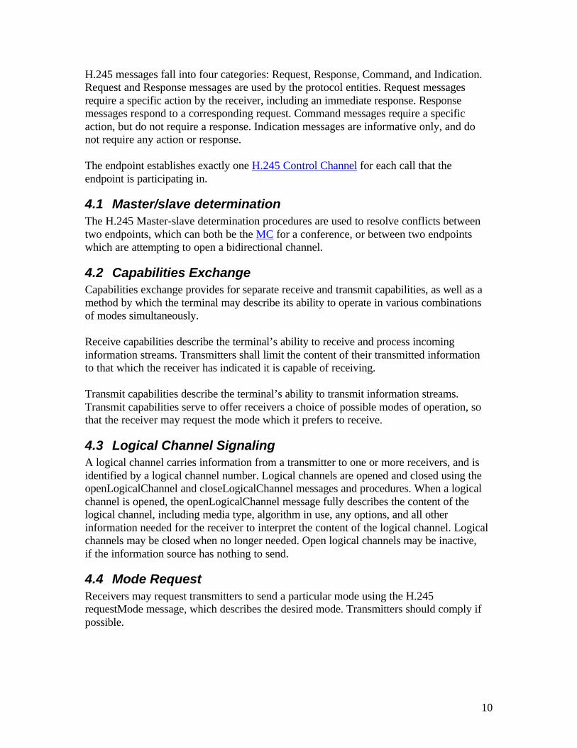
H.245 messages fall into four categories: Request, Response, Command, and Indication. Request and Response messages are used by the protocol entities. Request messages require a specific action by the receiver, including an immediate response. Response messages respond to a corresponding request. Command messages require a specific action, but do not require a response. Indication messages are informative only, and do not require any action or response. The endpoint establishes exactly one H.245 Control Channel for each call that the endpoint is participating in.
4.1 Master/slave determination The H.245 Master-slave determination procedures are used to resolve conflicts between two endpoints, which can both be the MC for a conference, or between two endpoints which are attempting to open a bidirectional channel.
4.2 Capabilities Exchange Capabilities exchange provides for separate receive and transmit capabilities, as well as a method by which the terminal may describe its ability to operate in various combinations of modes simultaneously. Receive capabilities describe the terminal’s ability to receive and process incoming information streams. Transmitters shall limit the content of their transmitted information to that which the receiver has indicated it is capable of receiving. Transmit capabilities describe the terminal’s ability to transmit information streams. Transmit capabilities serve to offer receivers a choice of possible modes of operation, so that the receiver may request the mode which it prefers to receive.
4.3 Logical Channel Signaling A logical channel carries information from a transmitter to one or more receivers, and is identified by a logical channel number. Logical channels are opened and closed using the openLogicalChannel and closeLogicalChannel messages and procedures. When a logical channel is opened, the openLogicalChannel message fully describes the content of the logical channel, including media type, algorithm in use, any options, and all other information needed for the receiver to interpret the content of the logical channel. Logical channels may be closed when no longer needed. Open logical channels may be inactive, if the information source has nothing to send.
4.4 Mode Request Receivers may request transmitters to send a particular mode using the H.245 requestMode message, which describes the desired mode. Transmitters should comply if possible.

11
4.5 H.245 Control Channel An endpoint establishes exactly one H.245 Control Channel for each call that the endpoint is participating in. This channel uses the messages and procedures of H.245. Note that an entitiy may support many calls, and thus many H.245 Control Channels. The H.245 Control Channel is carried on logical channel 0.
5 H.323 Call Walkthrough This section gives an example of how the various messages and procedures described above in sections 3 and 4 are used within a call scenario. Communication between two H.323 entities is made in the following steps:
• Phase 0: RAS (H.225) • Phase A: Call setup (H.225) • Phase B: Initial communication and capability exchange (H.245) • Phase C: Establishment of audiovisual communication (H.245) • Phase D: Call services (H.245, H.225) • Phase E: Call termination (H.245, H.225)
5.1 Phase 0: RAS Before a call is made, the endpoint may or may not register with a Gatekeeper as described in section 3.1. The Gatekeeper settings affect the procedures of the call below.
5.2 Phase A: Call setup Call setup takes place using the call control messages defined in H.225 according to the call control procedures defined below. Requests for bandwidth reservation should take place at the earliest possible phase. After any required RAS messages, the caller initiates a call with the Setup message. An endpoint sending the Setup message can expect to receive either an Alerting, Connect, Call Proceeding, or Release Complete message within 4 seconds after successful transmission. A called party can send the Alerting message in response. Alerting means that the called party has been alerted of an incoming call. If an endpoint can respond to a Setup message with a Connect, Call Proceeding, or Release Complete within 4 seconds, it is not required to send the Alerting message. The following two examples are but two configurations of endpoints and Gatekeepers parameters.
5.2.1 Basic call setup - Neither endpoint registered with Gatekeeper In this scenario (see Figure 8) neither endpoint is registered to a Gatekeeper. The two endpoints communicate directly. Endpoint 1 (call endpoint) sends the Setup (1) message to the well-known Call Signaling Channel of Endpoint 2. Endpoint 2 responds with the

12
Connect (4) message, which contains an H.245 Control Channel Transport Address for use in H.245 signaling.
Endpoint 1 Setup (1)
Connect (4)
Call proceeding (2)
Alerting (3)
Call Signaling Messages
Endpoint 2
Figure 8 - Basic call setup, no Gatekeepers
5.2.2 Both endpoints registered, both Gatekeepers routing In this scenario (see Figure 9), both endpoints are registered to different Gatekeepers, and both Gatekeepers choose to route the call signaling. Endpoint 1 (calling endpoint) initiates the ARQ (1)/ARQ (2) exchange with Gatekeeper 1. If accepted, endpoint 1 then sends the Setup (3) message to Gatekeeper 1. Gatekeeper 1 then sends the Setup (4) message to the well-known Call Signaling Channel of Endpoint 2. If Endpoint 2 wishes to accept the call, it initiates the ARQ (6)/ACF (7) exchange with Gatekeeper 2. If accepted, endpoint 2 replies to Gatekeeper 1 with a Facility (8) message containing the Call Signaling Address of Gatekeeper 2. Gatekeeper 1 then sends the Release Complete (9) message to endpoint 2. Gatekeeper 1 sends a Setup (10) message to Gatekeeper 2’s Call Signaling Channel. Gatekeeper 2 sends the Setup (11) message to Endpoint 2. Endpoint 2 initiates the ARQ (12)/ACF (13) exchange with Gatekeeper 2. Endpoint 2 then responds to Gatekeeper 2 with the Connect (15) message, which contains its H.245 Control Channel Transport Address for use in H.245 signaling. Gatekeeper 2 sends the Connect (16) message to Gatekeeper 1, which contains the Endpoint 2 H.245 Control Channel Transport Address. Gatekeeper 1 sends then Connect (17) message to Endpoint 1.

13
Endpoint 1 Gatekeeper 1 Gatekeeper 2 Endpoint 2
ARQ (6)
ARJ (7)
Facility (8)
Setup (4)
Call Proceeding (5)
Setup (10)
Call Proceeding (5)
Alerting (14)
Connect (16)
Setup (11)
Call Proceeding (5)
ARQ (12)
ACF/ARJ (13)
Alerting (14)
Connect (15)
RAS Messages Call Signalling Messages
ARQ (1)
ACF (2)
Setup (3)
Call Proceeding (5)
Alerting (14)
Connect (17)
Release Complete (9)
Figure 9 - Both endpoints registerd, both gatekeepers routing call signaling
5.3 Phase B: Initial communication and capability exchange Once both sides have exchanged call setup messages from Phase A, the endpoints establish the H.245 Control Channel. The procedures of H.245 are used over the H.245 Control Channel for the capability exchange and to open the media channels. Endpoint system capabilities are exchanged by transmission of the H.245 terminalCapabilitySet message. This capability message should be the first H.245 sent. Then the master-slave determination procedure should take place. If the initial capability exchange or master-slave determination procedures fail, these should be retried at least two additional times before the endpoint abandons the connection attempt and proceeds to Phase E. Following this exchange of capabilities, the endpoints proceed directly to Phase C.
14
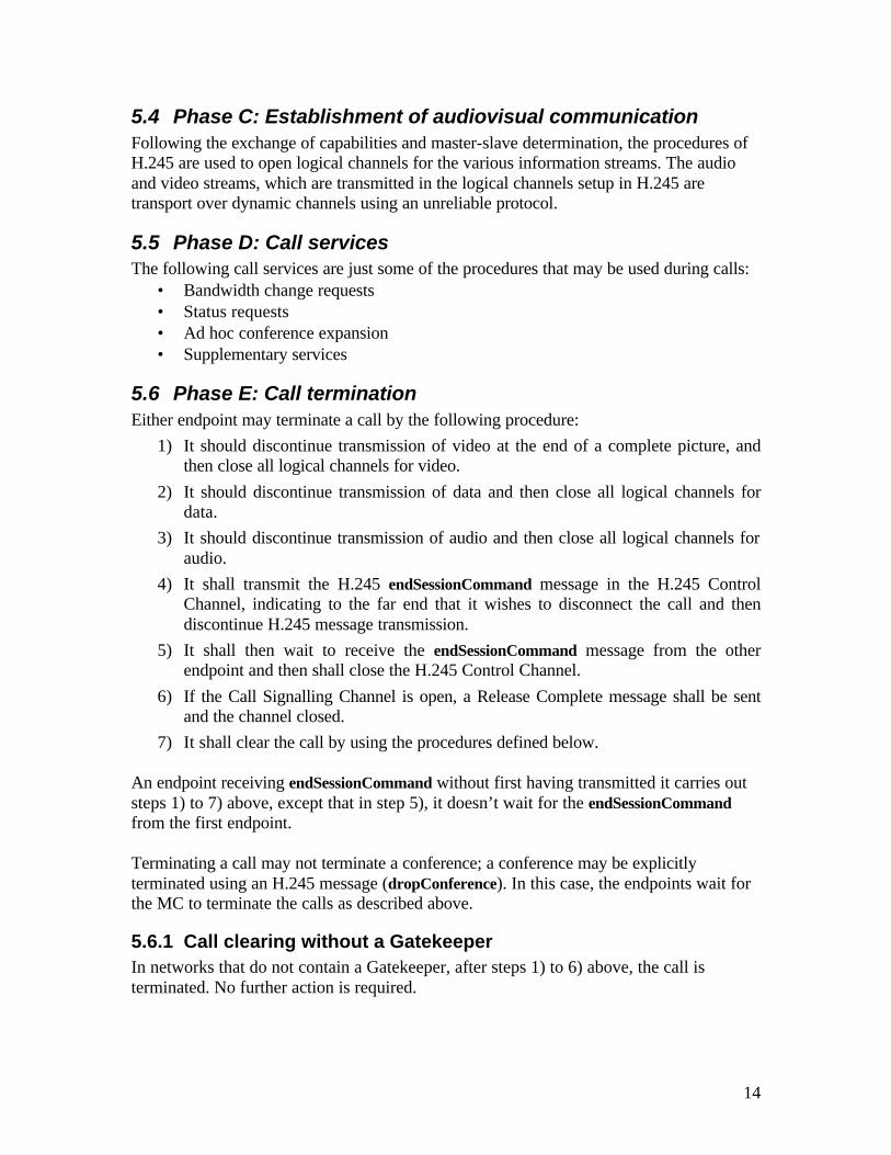
5.4 Phase C: Establishment of audiovisual communication Following the exchange of capabilities and master-slave determination, the procedures of H.245 are used to open logical channels for the various information streams. The audio and video streams, which are transmitted in the logical channels setup in H.245 are transport over dynamic channels using an unreliable protocol.
5.5 Phase D: Call services The following call services are just some of the procedures that may be used during calls:
• Bandwidth change requests • Status requests • Ad hoc conference expansion • Supplementary services
5.6 Phase E: Call termination Either endpoint may terminate a call by the following procedure:
1) It should discontinue transmission of video at the end of a complete picture, and then close all logical channels for video.
2) It should discontinue transmission of data and then close all logical channels for data.
3) It should discontinue transmission of audio and then close all logical channels for audio.
4) It shall transmit the H.245 endSessionCommand message in the H.245 Control Channel, indicating to the far end that it wishes to disconnect the call and then discontinue H.245 message transmission.
5) It shall then wait to receive the endSessionCommand message from the other endpoint and then shall close the H.245 Control Channel.
6) If the Call Signalling Channel is open, a Release Complete message shall be sent and the channel closed.
7) It shall clear the call by using the procedures defined below. An endpoint receiving endSessionCommand without first having transmitted it carries out steps 1) to 7) above, except that in step 5), it doesn’t wait for the endSessionCommand from the first endpoint. Terminating a call may not terminate a conference; a conference may be explicitly terminated using an H.245 message (dropConference). In this case, the endpoints wait for the MC to terminate the calls as described above.
5.6.1 Call clearing without a Gatekeeper In networks that do not contain a Gatekeeper, after steps 1) to 6) above, the call is terminated. No further action is required.

15
5.6.2 Call clearing with a Gatekeeper In networks that contain a Gatekeeper, the Gatekeeper needs to know about the release of bandwidth. After performing steps 1) to 6) above, each endpoint shall transmit an H.225.0 Disengage Request (DRQ) message (3) to its Gatekeeper. The Gatekeeper shall respond with a Disengage Confirm (DCF) message (4). After sending the DRQ message, the endpoints shall not send further unsolicited IRR messages to the Gatekeeper (see Figure 10). At this point, the call is terminated. Figure 10 shows the direct call model. The DRQ and DCF messages are sent on the RAS Channel.
Gatekeeper 1 Endpoint 1 Endpoint 2 Gatekeeper 2
DRQ (3)
DCF (4)
EndSessionCommand (1)
EndSessionCommand (1)
Release Complete (2)
DRQ (3)
DCF (4)
RAS messages Call Signalling messages H.245 messages
NOTE – Gatekeeper 1 and Gatekeeper 2 may be the same Gatekeeper.
Figure 10 - Endpoint initiated call clearing
5.6.3 Call clearing by Gatekeeper The Gatekeeper may terminate call by sending a DRQ to an endpoint (see Figure 11). The endpoint immediately follows steps 1) through 6) from above and then replies to the Gatekeeper with DCF. The other endpoint, upon receiving endSessionCommand, follows the procedure described above. If the conference is a multipoint conference, the Gatekeeper should send a DRQ to each endpoint in the conference, in order to close the entire conference.

16
Gatekeeper 1 Endpoint 1 Endpoint 2 Gatekeeper 2
DRQ (3)
DCF (4)
EndSessionCommand (1)
EndSessionCommand (1)
Release Complete (2) DRQ (3)
DCF (4)
RAS messages Call Signalling messages H.245 messages
NOTE – Gatekeeper 1 and Gatekeeper 2 may be the same Gatekeeper.
Figure 11 - Gatekeeper initiated call clearing
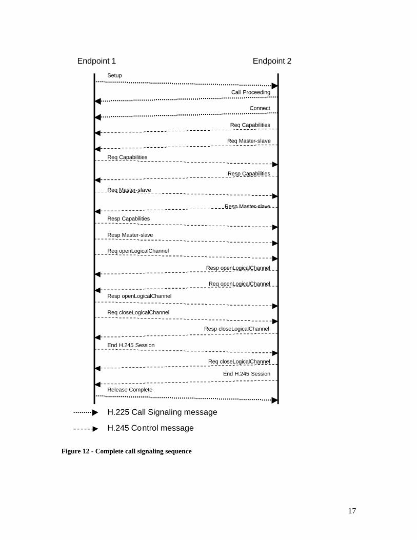
5.7 Summary This section attempts to tie together the procedures described above. The following is a ladder diagram of a complete call sequence going through Phases A-E.
17
Setup
Call Proceeding
Connect
Req Capabilities
Req Master-slave
Req Capabilities
Resp Capabilities
Req Master-slave
Resp Master-slave
Resp Master-slave
Resp Capabilities
Req openLogicalChannel
Req openLogicalChannel
Resp openLogicalChannel
Resp openLogicalChannel
Req closeLogicalChannel
Resp closeLogicalChannel
Req closeLogicalChannel
End H.245 Session
End H.245 Session
Release Complete
Endpoint 1 Endpoint 2
H.225 Call Signaling message
H.245 Control message
Figure 12 - Complete call signaling sequence

18
5.7.1 Channels This section summarizes the channels involved in an H.323 call. H.225 call signaling is performed on the Call Signaling Channel. RAS signaling is performed on the RAS channel. Both channels are well-known and reliable. After call setup, H.245 procedures are performed on the H.245 Control Channel, which is dynamically created. Any information streams are sent through logical channels created by H.245 messages, such as openLogicalChannel. These logical channels carry audio and video and are dynamic and unreliable. The following table is a summary of the channels involved in an H.323 call:
Channel Reliable or unreliable Well known or dynamic
Audio/RTP Unreliable Dynamic
Audio/RTCP Unreliable Dynamic
Video/RTP Unreliable Dynamic
Video/RTCP Unreliable Dynamic
Call Signaling Reliable Well known or dynamic
H.245 Reliable Dynamic
Data (T.120) Reliable Well known or dynamic
RAS Unreliable Well known or dynamic
NOTE – If well known TSAP identifiers are used, there can only be a single endpoint per network address. Also, in the direct call model the caller requires a well known TSAP identifier for the Call Signalling channel to start the call.
Figure 13 - Table of channels used in an H.323 call
6 Audio Codecs All H.323 terminals must support an audio codec. All H.323 terminals must be capable of encoding and decoding speech according to Recommendation G.711. Furthermore, all terminals must be capable of transmitting and receiving A-law and µ-law. A terminal may optionally be capable of encoding and decoding speech using Recommendations G722, G.728, G.729, MPEG 1 audio, and G.723.1. The audio algorithm used by the encoder is determined during the capability exchange using H.245 (see section 4.2). The H.323 terminal should be capable of asymmetric operation for all audio capabilities it has declared within the same capability set. The audio stream is formatted in the H.225 layer as described in H.225.
7 Video Codecs The video codec is optional. All H.323 terminals providing video communications must be capable of encoding and decoding video according to H.261 QCIF. Optionally, a terminal may also be capable of encoding and decoding video according to the other modes of H.261 or H.263. Other video codecs, and other picture formats, may also be
19
used via H.245 negotiation. The H.323 terminals should be capable of asymmetric operation for all video capabilities it has declared within the same capability set. The video stream is formatted in the H.225 layer as described in H.225.
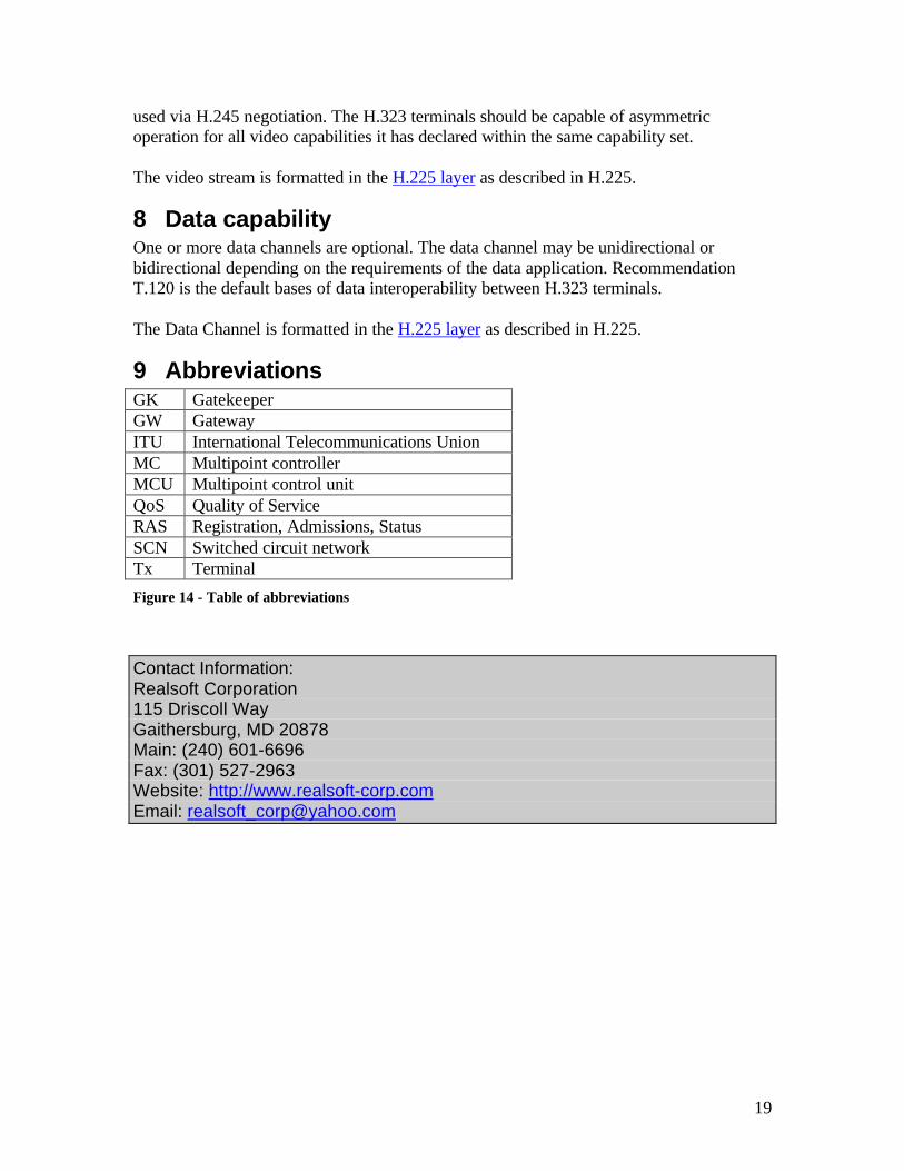
8 Data capability One or more data channels are optional. The data channel may be unidirectional or bidirectional depending on the requirements of the data application. Recommendation T.120 is the default bases of data interoperability between H.323 terminals. The Data Channel is formatted in the H.225 layer as described in H.225.
9 Abbreviations GK Gatekeeper GW Gateway ITU International Telecommunications Union MC Multipoint controller MCU Multipoint control unit QoS Quality of Service RAS Registration, Admissions, Status SCN Switched circuit network Tx Terminal
Figure 14 - Table of abbreviations
Contact Information: Realsoft Corporation 115 Driscoll Way Gaithersburg, MD 20878 Main: (240) 601-6696 Fax: (301) 527-2963 Website: http://www.realsoft-corp.com Email: [email protected]