H265 32 and 16 channel NVR 2U User Manual
91
1 H265 32 and 16 channel NVR 2U User Manual
Transcript of H265 32 and 16 channel NVR 2U User Manual
1
H265 32 and 16 channel
NVR 2U
User Manual

2
Please read this manual thoroughly before use and keep it handy for future reference.
3
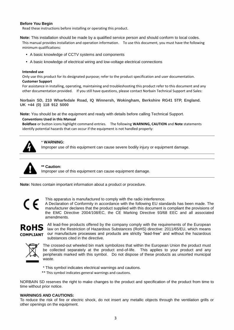
Before You Begin
Read these instructions before installing or operating this product.
Note: This installation should be made by a qualified service person and should conform to local codes.
This manual provides installation and operation information. To use this document, you must have the following minimum qualifications:
A basic knowledge of CCTV systems and components
A basic knowledge of electrical wiring and low-voltage electrical connections
Intended use Only use this product for its designated purpose; refer to the product specification and user documentation. Customer Support For assistance in installing, operating, maintaining and troubleshooting this product refer to this document and any other documentation provided. If you still have questions, please contact Norbain Technical Support and Sales:
Norbain SD, 210 Wharfedale Road, IQ Winnersh, Wokingham, Berkshire RG41 5TP, England. UK +44 (0) 118 912 5000
Note: You should be at the equipment and ready with details before calling Technical Support.
Conventions Used in this Manual Boldface or button icons highlight command entries. The following WARNING, CAUTION and Note statements identify potential hazards that can occur if the equipment is not handled properly:
* WARNING:
Improper use of this equipment can cause severe bodily injury or equipment damage.
** Caution: Improper use of this equipment can cause equipment damage.
Note: Notes contain important information about a product or procedure.
This apparatus is manufactured to comply with the radio interference. A Declaration of Conformity in accordance with the following EU standards has been made. The manufacturer declares that the product supplied with this document is compliant the provisions of the EMC Directive 2004/108/EC, the CE Marking Directive 93/68 EEC and all associated amendments.
All lead-free products offered by the company comply with the requirements of the European law on the Restriction of Hazardous Substances (RoHS) directive: 2011/65/EU, which means our manufacture processes and products are strictly “lead-free” and without the hazardous substances cited in the directive.
The crossed-out wheeled bin mark symbolizes that within the European Union the product must be collected separately at the product end-of-life. This applies to your product and any peripherals marked with this symbol. Do not dispose of these products as unsorted municipal waste.
* This symbol indicates electrical warnings and cautions.
** This symbol indicates general warnings and cautions. NORBAIN SD reserves the right to make changes to the product and specification of the product from time to time without prior notice. WARNINGS AND CAUTIONS: To reduce the risk of fire or electric shock, do not insert any metallic objects through the ventilation grills or other openings on the equipment.
4
IMPORTANT SAFEGUARDS
1. Read these instructions.
2. Keep these instructions.
3. Heed all warnings.
4. Follow all instructions.
5. Do not use this apparatus near water.
6. Clean only with dry cloth.
7. Do not block any ventilation openings. Install in accordance with the manufacturer's instructions.
8. Do not install near any heat sources such as radiators, heat registers, stoves, or other apparatus (including amplifiers) that
product heat.
9. Do not defeat the safety purpose of the polarized or grounding-type plug. A polarized plug has two blades with one wider than
the other. A grounding type plug has two blades and a third grounding prong. The wide blade or the third prong is provided for
your safety. If the provided plug does not fit into your outlet, consult an electrician for replacement of the obsolete outlet.
10. Protect the power cord from being walked on or pinched particularly at plugs, convenience receptacles, and the point where
they exit from the apparatus.
11. Only use attachments/accessories specified by the manufacturer.
12. Unplug this apparatus during lightning storms or when unused for long periods of time.
13. Refer all servicing to qualified service personnel. Servicing is required when the apparatus has been damaged in any way,
such as power-supply cord or plug is damaged, liquid has been spilled or objects have fallen into the apparatus, the apparatus
has been exposed to rain or moisture, does not operate normally, or has been dropped.
14. CAUTION - THESE SERVICING INSTRUCTIONS ARE FOR USE BY QUALIFIED SERVICE PERSONNEL ONLY. TO
REDUCE THE RISK OF ELECTRIC SHOCK DO NOT PERFORM ANY SERVICING OTHER THAN THAT CONTAINED IN THE
OPERATING INSTRUCTIONS UNLESS YOU ARE QUALIFIED TO DO SO.
15. IEC60950-1/UL60950-1 or Certified/Listed Class 2 power source only. CE COMPLIANCE STATEMENT
WARNING This is a Class A product. In a domestic environment this product may cause radio interference in which case the user may be required to take adequate measures.
CAUTION RISK OF EXPLOSION IF BATTERY IS REPLACED BY AN INCORRECT TYPE. DISPOSE OF USED BATTERIES ACCORDING TO THE INSTRUCTIONS.

VIPER-H5 manual V1.0
1
Table of Contents
Before You Begin 3
Intended use 3
Customer Support 3
WARNINGS AND CAUTIONS: 3
Table of Contents ................................................................................................................................. 1
1. Overview 3
1.1 Package Contents ...................................................................................................................... 3
1.2 Part Description ......................................................................................................................... 3
2. Installation 5
2.1 Connection of exterior devices ..................................................................................................... 6
2.2 Starting System ......................................................................................................................... 7
2.3 Quick set up .............................................................................................................................. 8
2.3.1 Account........................................................................................................................ 8
2.3.2 System ......................................................................................................................... 9
2.3.3 Network ..................................................................................................................... 10
2.3.4 Time/Date .................................................................................................................. 11
3. Live Screen Configuration 12
3.1 Icons in Live screen .................................................................................................................. 14
3.2 Live Launcher menu ................................................................................................................. 15
3.2.1 Backup (Down loading of video footage) ....................................................................... 16
3.3 Quick menu ............................................................................................................................. 17
3.3.1 PTZ Control ................................................................................................................ 18
3.3.2 Camera Registration .................................................................................................... 20
3.3.3 Status > System log .................................................................................................... 21
3.3.4 Status > Event............................................................................................................ 22
3.3.5 Status > Record .......................................................................................................... 23
3.3.6 Status > Disk.............................................................................................................. 24
4. Setup menu 25
VIPER-H5 manual V1.0
2
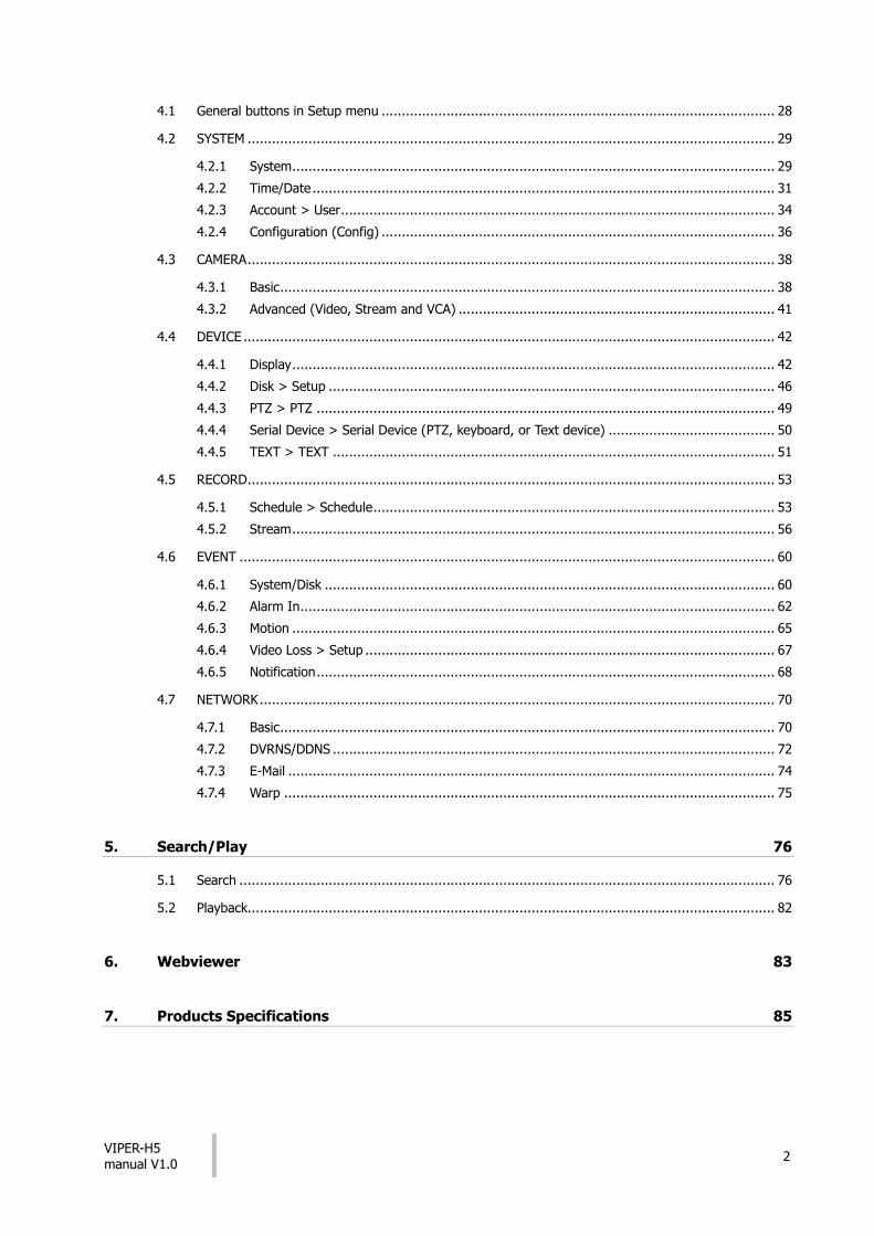
4.1 General buttons in Setup menu ................................................................................................. 28
4.2 SYSTEM .................................................................................................................................. 29
4.2.1 System ....................................................................................................................... 29
4.2.2 Time/Date .................................................................................................................. 31
4.2.3 Account > User ........................................................................................................... 34
4.2.4 Configuration (Config) ................................................................................................. 36
4.3 CAMERA .................................................................................................................................. 38
4.3.1 Basic .......................................................................................................................... 38
4.3.2 Advanced (Video, Stream and VCA) .............................................................................. 41
4.4 DEVICE ................................................................................................................................... 42
4.4.1 Display ....................................................................................................................... 42
4.4.2 Disk > Setup .............................................................................................................. 46
4.4.3 PTZ > PTZ ................................................................................................................. 49
4.4.4 Serial Device > Serial Device (PTZ, keyboard, or Text device) ......................................... 50
4.4.5 TEXT > TEXT ............................................................................................................. 51
4.5 RECORD .................................................................................................................................. 53
4.5.1 Schedule > Schedule ................................................................................................... 53
4.5.2 Stream ....................................................................................................................... 56
4.6 EVENT .................................................................................................................................... 60
4.6.1 System/Disk ............................................................................................................... 60
4.6.2 Alarm In ..................................................................................................................... 62
4.6.3 Motion ....................................................................................................................... 65
4.6.4 Video Loss > Setup ..................................................................................................... 67
4.6.5 Notification ................................................................................................................. 68
4.7 NETWORK ............................................................................................................................... 70
4.7.1 Basic .......................................................................................................................... 70
4.7.2 DVRNS/DDNS ............................................................................................................. 72
4.7.3 E-Mail ........................................................................................................................ 74
4.7.4 Warp ......................................................................................................................... 75
5. Search/Play 76
5.1 Search .................................................................................................................................... 76
5.2 Playback.................................................................................................................................. 82
6. Webviewer 83
7. Products Specifications 85
VIPER-H5 manual V1.0
3
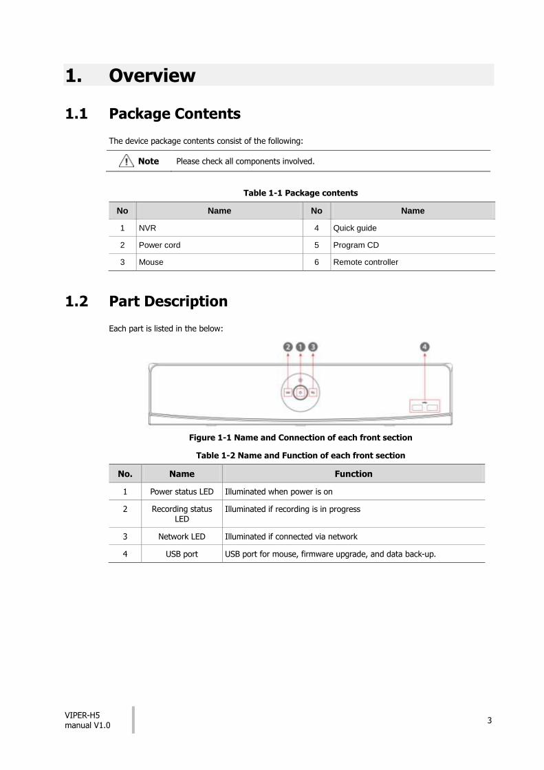
1. Overview
1.1 Package Contents
The device package contents consist of the following:
Note Please check all components involved.
Table 1-1 Package contents
No Name No Name
1 NVR 4 Quick guide
2 Power cord 5 Program CD
3 Mouse 6 Remote controller
1.2 Part Description
Each part is listed in the below:
Figure 1-1 Name and Connection of each front section
Table 1-2 Name and Function of each front section
No. Name Function
1 Power status LED Illuminated when power is on
2 Recording status
LED Illuminated if recording is in progress
3 Network LED Illuminated if connected via network
4 USB port USB port for mouse, firmware upgrade, and data back-up.

VIPER-H5 manual V1.0
4
Figure 1-2 Name and Connection of rear section of 16ch, and 32ch NVR
Table 1-3 Name and Function of rear section of 16ch, and 32ch NVR
No. Name Function
1 IP CAM / PoE IP camera input port, IEEE802.3at PoE support
2 Audio In Audio input port
3 Audio Out Audio output port
4 VGA VGA output port
5 HD Output HD output port
6 Network Network connector
7 Alarm In/Out Alarm connector
8 RS485 RS-485 communication connector
9 e-SATA e-SATA storage connection connector
10 USB 3.0 USB 3.0 port is connected for data back-up

VIPER-H5 manual V1.0
5
2. Installation
Connect external devices as per the diagram below.
Figure 2-1 Connection map
VIPER-H5 manual V1.0
6
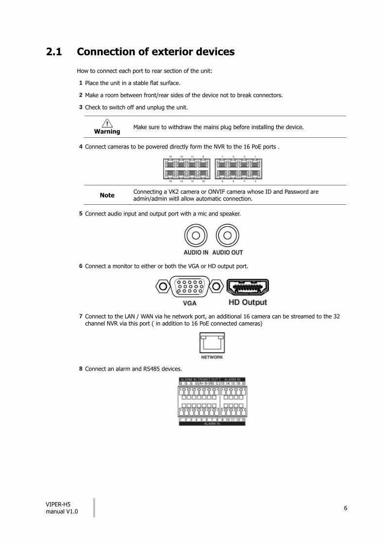
2.1 Connection of exterior devices
How to connect each port to rear section of the unit:
1 Place the unit in a stable flat surface.
2 Make a room between front/rear sides of the device not to break connectors.
3 Check to switch off and unplug the unit.
Warning Make sure to withdraw the mains plug before installing the device.
4 Connect cameras to be powered directly form the NVR to the 16 PoE ports .
Note Connecting a VK2 camera or ONVIF camera whose ID and Password are admin/admin witll allow automatic connection.
5 Connect audio input and output port with a mic and speaker.
6 Connect a monitor to either or both the VGA or HD output port.
7 Connect to the LAN / WAN via he network port, an additional 16 camera can be streamed to the 32 channel NVR via this port ( in addition to 16 PoE connected cameras)
8 Connect an alarm and RS485 devices.

VIPER-H5 manual V1.0
7
9 Connect an e-SATA storage.
10 Connect USB port for data back-up.
11 Supply the main power after completion.
2.2 Starting System
1 When initially powered up the NVR will display the following icons in order.
Note Installing new HDD might take more initialize time.
2 When fully booted a buzzer will sound and the live screen will be displayed
3 In Log in screen, enter the ID, Password and press OK.
Note Default ID & Password is admin/admin
Attention Please change password after login due to security.
Power Switch

VIPER-H5 manual V1.0
8
2.3 Quick set up
Quick set up can be used to set the basic system settings
2.3.1 Account
1. Click the keyboard icon to set ID and Password for users. .
2. With keyboard UI, set the ID and Password, and press OK.
Note Max character length is 16.
3.Press the Save button to save newly set ID and Password.
4. Press Next button to move to the next set up stage
VIPER-H5 manual V1.0
9
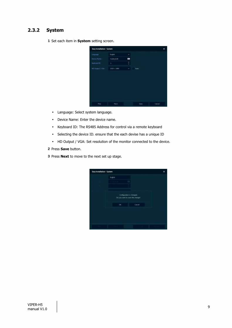
2.3.2 System
1 Set each item in System setting screen.
Language: Select system language.
Device Name: Enter the device name.
Keyboard ID: The RS485 Address for control via a remote keyboard
Selecting the device ID. ensure that the each devise has a unique ID
HD Output / VGA: Set resolution of the monitor connected to the device.
2 Press Save button.
3 Press Next to move to the next set up stage.

VIPER-H5 manual V1.0
10
2.3.3 Network
1 Set each item in Network setting screen.
WAN Port: Select whether to use static IP or dynamic IP.
IP Address, Subnet Mask, Gateway, DNS, and Port: As for dynamic IP, enter information in each space.
2 Press Save button to save set value.
3 Press Next to move to the next set up stage
VIPER-H5 manual V1.0
11
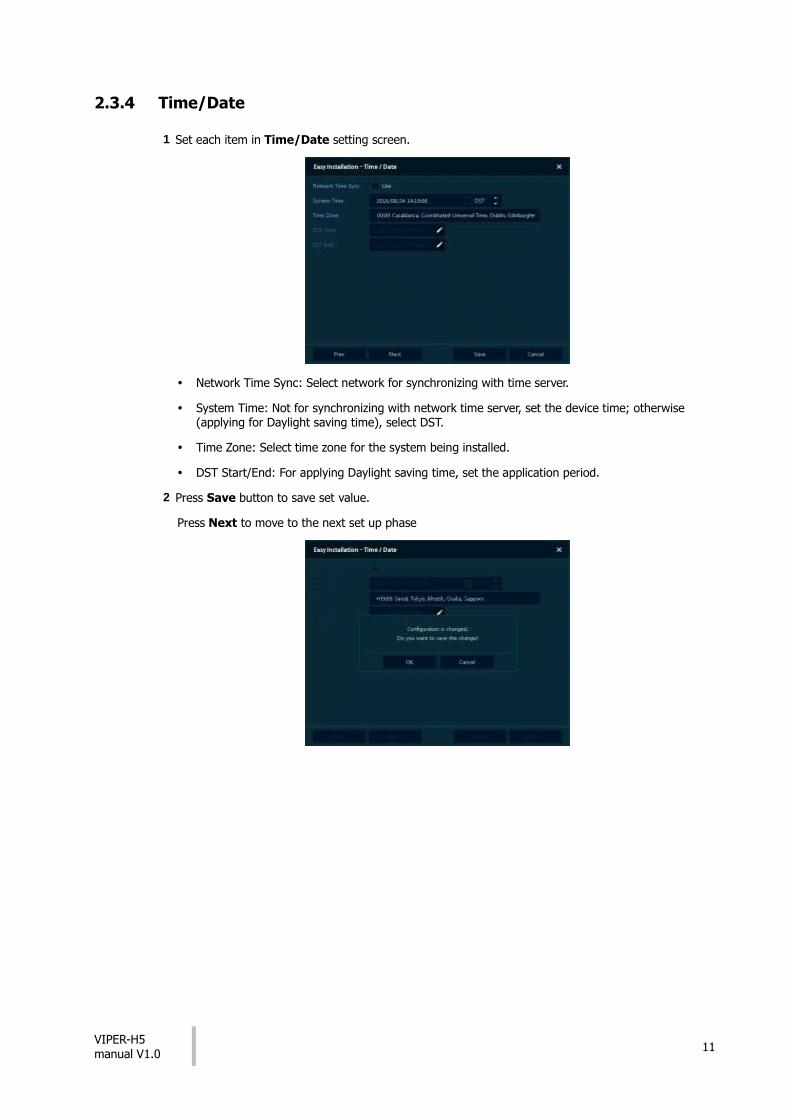
2.3.4 Time/Date
1 Set each item in Time/Date setting screen.
Network Time Sync: Select network for synchronizing with time server.
System Time: Not for synchronizing with network time server, set the device time; otherwise (applying for Daylight saving time), select DST.
Time Zone: Select time zone for the system being installed.
DST Start/End: For applying Daylight saving time, set the application period.
2 Press Save button to save set value.
Press Next to move to the next set up phase

VIPER-H5 manual V1.0
12
3. Live Screen Configuration
Figure 3-1 UI Screen Configuration
Table 3-1 Items and Description of UI Screen Configuration
No. Item Description
1 Setting menu Setting menu is located on the top edge of the screen. See section
“04 Setup ” for more detailed information
2 Live screen Show live video of connected cameras.
3 Launcher menu Launcher menu is located on the bottom edge of screen. See section “3.2 Live Launcher ” for more detailed information.
4 Quick menu Clicking the right mouse button to display the Quick menu. See section “0
No. Item Description
1 Select CH Selecting a channel users want to back-up
2 Select All/ Unselect All
Select or clear all channels.
3 Start Setting back-up start time (Bookmark: bookmark list).
4 End Setting back-up ending time (Bookmark: bookmark list).
5 Device Selecting the device to save back-up files
6 Reload Opening the device information
7 Folder Entering a folder name to save

VIPER-H5 manual V1.0
13
No. Item Description
Name back-up files
8 File format Selecting a file format to back-up
9 Calculate Calculating data capacity to back-up
10 Format Formatting the device to back-up
11 Start Starting back-up
12 Cancel Closing the backup screen
Quick ” for more detailed information.

VIPER-H5 manual V1.0
14
3.1 Icons in Live screen
Note Chosen live screen is framed by a blue border; the segment that the mouse is located in is framed by a yellow border.
Figure 3-2 Live screen icon
Table 3-2 Live screen icon and its description
No. Icon Description
1 CH1 CAM1 Channel numbers and camera titles
2 A camera with PTZ function
3 PTZ control function in process
4 Recording in alarm event mode
5 Recording in motion event mode
6 Recording in panic recording mode
7 Recording in consecutive recording mode
8 Video loss icon
9 Mic ON/OFF
10 Speaker ON/OFF
11 Displaying present date and time
VIPER-H5 manual V1.0
15
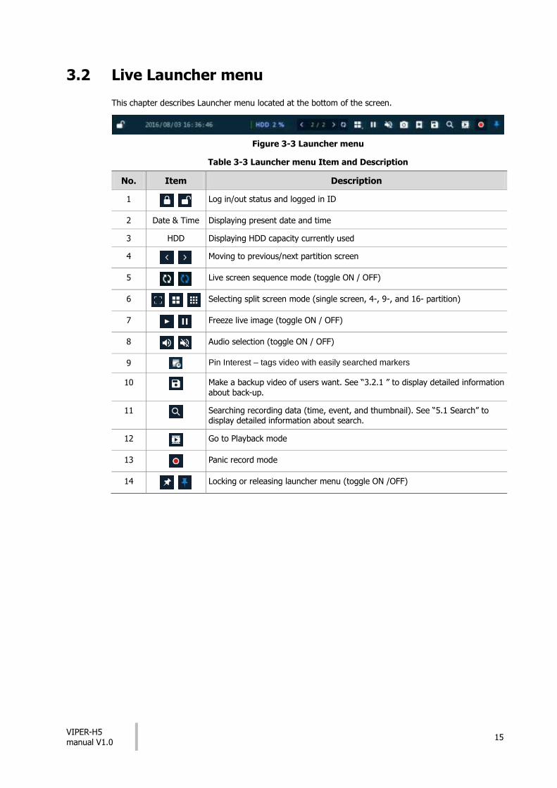
3.2 Live Launcher menu
This chapter describes Launcher menu located at the bottom of the screen.
Figure 3-3 Launcher menu
Table 3-3 Launcher menu Item and Description
No. Item Description
1 Log in/out status and logged in ID
2 Date & Time Displaying present date and time
3 HDD Displaying HDD capacity currently used
4 Moving to previous/next partition screen
5 Live screen sequence mode (toggle ON / OFF)
6 Selecting split screen mode (single screen, 4-, 9-, and 16- partition)
7 Freeze live image (toggle ON / OFF)
8 Audio selection (toggle ON / OFF)
9 Pin Interest – tags video with easily searched markers
10 Make a backup video of users want. See “3.2.1 ” to display detailed information about back-up.
11 Searching recording data (time, event, and thumbnail). See “5.1 Search” to display detailed information about search.
12 Go to Playback mode
13 Panic record mode
14 Locking or releasing launcher menu (toggle ON /OFF)

VIPER-H5 manual V1.0
16
3.2.1 Backup (Down loading of video footage)
Figure 3-4 Backup
Table 3-4 Backup Item and Description
No. Item Description
1 Select CH Selecting a channel users want to back-up
2 Select All/ Unselect All
Select or clear all channels.
3 Start Setting back-up start time (Bookmark: bookmark list).
4 End Setting back-up ending time (Bookmark: bookmark list).
5 Device Selecting the device to save back-up files
6 Reload Opening the device information
7 Folder Name Entering a folder name to save back-up files
8 File format Selecting a file format to back-up
9 Calculate Calculating data capacity to back-up
10 Format Formatting the device to back-up
11 Start Starting back-up
12 Cancel Closing the backup screen

VIPER-H5 manual V1.0
17
3.3 Quick menu
Right click anywhere on the screen to display the Quick menu.
Figure 3-5 Quick menu
Table 3-5 Quick menu Item and Description
No. Item Description
1 Screen Mode Select the split screen mod to be displayed (Full, 2X2, 3X3, and 4x4).
2 Zoom in Magnify the selected live full screen image (Zoom out, 2 times, 4 times,
and 8 times).
3 Freeze Freezes the video selected live screen images (toggle on / off).
4 Speaker Output/Mute
Turning on/off a sound speaker
5 PTZ Control Controlling PTZ Function
6 Stop Alarm Stop the alarm sounder
7 Playback Playing selected live screen images (from 30 sec, 1 min, 5 min, 10 min, 30 min, 1-hour, Go to last play time, and Go to last record time)
8 Search Go to the search screen (time, event, thumbnail, and text). See section “5.1 Search” for more detailed information.
9 Backup Go to the Back up screen. See section “3.2.1 ” for more detailed information
10 Setup Opens the DVRs main set up menu. For more information about set up menu, see section “4 Setup .”
11 Warp Monitor and control for remote recorder.
12 Camera Registration
Opens a pop-up displays IP camera registration.
13 Status Opens a pop-up menu showing: device system log, event, and recording status (system log, event, and record).
14 Log in/Log out Log in/Log out.
15 Shutdown Shuts down or restarts the device (shutdown, restart).

VIPER-H5 manual V1.0
18
3.3.1 PTZ Control
Note PTZ Control menu can be displayed if relevant channel’s protocol is set in DEVICE > PTZ in the upper live screen.
Figure 3-6 Quick menu > PTZ Control
Table 3-6 Quick menu > PTZ Control Item and Description
No. Item Description
1
Direction control buttons
2 Place cursor on this spot , click and drag to make PTZ camera move
3 AF Adjusting screen focus automatically
4 Zoom Out
Zoom function of PTZ camera
5 Zoom In
6 IRIS OFF
Iris adjustment
7 IRIS On
8 Focus Far
Manual focus adjustment
9 Focus Near
10 Go to Home menu
11 Camera Menu button

VIPER-H5 manual V1.0
19
In PTZ Control screen, clicking the right button of the mouse displays Quick menu.
Figure 3-7 PTZ Control Quick menu
Table 3-7 PTZ Control Item and Description in Quick menu
No. Item Description
1 Preset Go Go to a preset position
2 Preset Save Save a preset position
3 Tour Run Tour function.
4 Scan Run Scan function.
5 Pattern Run Pattern function.
6 Exit Exit to live screen menu in PTZ Control menu

VIPER-H5 manual V1.0
20
3.3.2 Camera Registration
Connection of IP camera to the NVR
Figure 3-8 Camera Registration
Table 3-8 Camera Registration
No. Item Description
1 Search for connected IP cameras.
2 Auto Assign Automatically assign channel numbers
3 Port Show the detected camera port (WAN or PoE).
4 Assign Selecting the channel windows manually.
5 Model Show detected camera model number.
6 IP Show detected camera IP address.
7 Status Show connection status.

VIPER-H5 manual V1.0
21
3.3.3 Status > System log
The system log information can be seen in the System log tab in Status screen.
Figure 3-9 Status > System log in Quick menu
Table 3-9 Status of Quick menu > System log Item and Description
No. Item Description
1 Start Set the starting time of system log to be searched
2 End Set the end time of system log to be search
3 Log Type Selecting log types (Network, Record, Setup, Disk, Backup, and System)
4 Select All /Unselect All
Selecting or clearing all log types (toggle).
5 Pressing search button search on the basis of set condition
6 System log list Displays system log lists
7 USB Export Export the log data to USB thumb drive.
8 Cancel Exit

VIPER-H5 manual V1.0
22
3.3.4 Status > Event
The real-time event information of the unit in Event tab in Status screen.
Figure 3-10 Status > Event in Quick menu
Table 3-10 Status > Event Item and Description in Quick menu
No. Item Description
1 Temporary fixing or releasing an event list (toggle).
2 Refresh Deleting the event list
3 Event list Displaying the event list
4 Cancel Exit the status screen

VIPER-H5 manual V1.0
23
3.3.5 Status > Record
Users can see the recording status in Record tab in Status screen.
Figure 3-11 Status > Record in Quick menu
Table 3-11 Status > Record Item and Description in Quick menu
No. Item Description
1 Record time Displays the first and last recorded time
2 Record list Displays the record setting status
3 Cancel Exit
VIPER-H5 manual V1.0
24
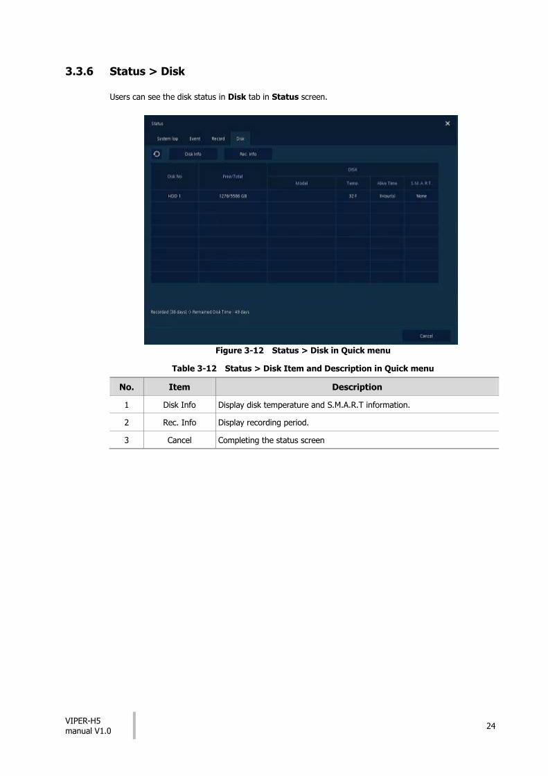
3.3.6 Status > Disk
Users can see the disk status in Disk tab in Status screen.
Figure 3-12 Status > Disk in Quick menu
Table 3-12 Status > Disk Item and Description in Quick menu
No. Item Description
1 Disk Info Display disk temperature and S.M.A.R.T information.
2 Rec. Info Display recording period.
3 Cancel Completing the status screen
VIPER-H5 manual V1.0
25
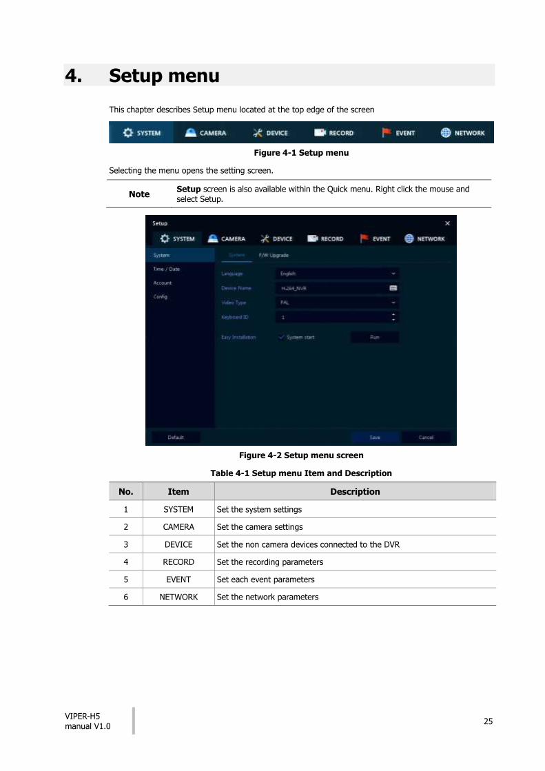
4. Setup menu
This chapter describes Setup menu located at the top edge of the screen
Figure 4-1 Setup menu
Selecting the menu opens the setting screen.
Note Setup screen is also available within the Quick menu. Right click the mouse and select Setup.
Figure 4-2 Setup menu screen
Table 4-1 Setup menu Item and Description
No. Item Description
1 SYSTEM Set the system settings
2 CAMERA Set the camera settings
3 DEVICE Set the non camera devices connected to the DVR
4 RECORD Set the recording parameters
5 EVENT Set each event parameters
6 NETWORK Set the network parameters

VIPER-H5 manual V1.0
26
Setup menu includes:
Table 4-2 Setup menu tree
Level 1 Level 2 Level 3
SYSTEM
System System
F/W Upgrade
Time/Date Time/Date
Holiday
Account User
Configuration Export/Import
Factory Default
CAMERA
Basic Basic
Audio In
Advanced Advanced
DEVICE
Display
Display
OSD
Sequence
Disk Setup
iSCSI
PTZ PTZ
Serial Device Serial Device
TEXT TEXT
RECORD
Schedule Schedule
Stream
Main Stream
Second Stream
Panic
EVENT
System/Disk System
Disk
Alarm In Setup
Schedule
Motion Setup
Schedule
Video Loss Setup
Notification Periodic
Schedule

VIPER-H5 manual V1.0
27
Level 1 Level 2 Level 3
NETWORK
Basic WAN Port
DVRNS/DDNS DVRNS/Dashboard
DDNS
E-Mail E-Mail
VIPER-H5 manual V1.0
28
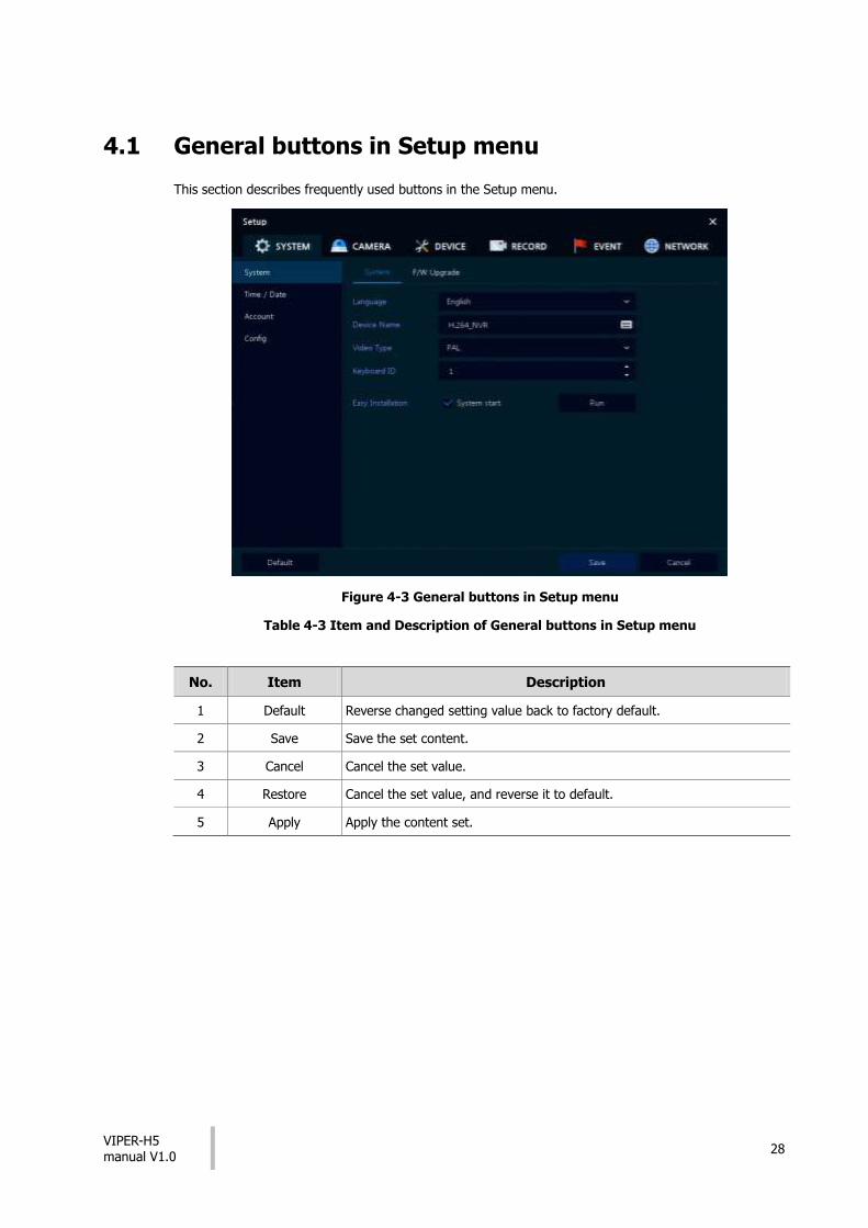
4.1 General buttons in Setup menu
This section describes frequently used buttons in the Setup menu.
Figure 4-3 General buttons in Setup menu
Table 4-3 Item and Description of General buttons in Setup menu
No. Item Description
1 Default Reverse changed setting value back to factory default.
2 Save Save the set content.
3 Cancel Cancel the set value.
4 Restore Cancel the set value, and reverse it to default.
5 Apply Apply the content set.
VIPER-H5 manual V1.0
29
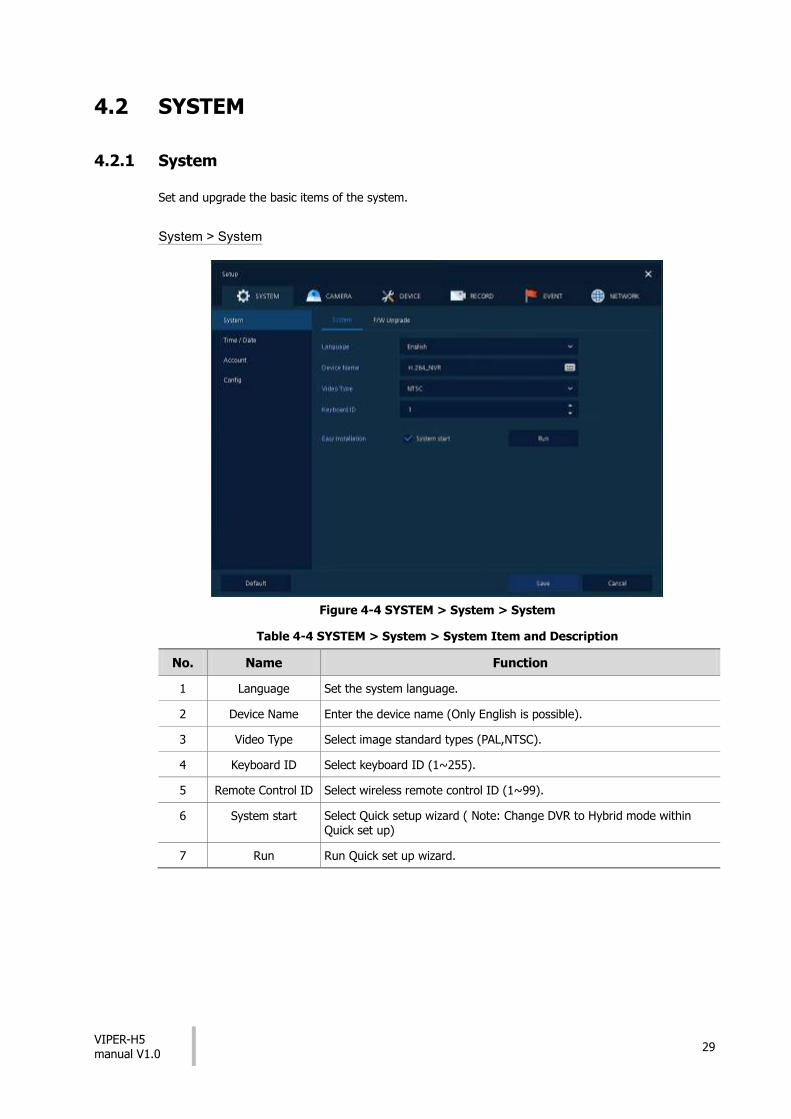
4.2 SYSTEM
4.2.1 System
Set and upgrade the basic items of the system.
System > System
Figure 4-4 SYSTEM > System > System
Table 4-4 SYSTEM > System > System Item and Description
No. Name Function
1 Language Set the system language.
2 Device Name Enter the device name (Only English is possible).
3 Video Type Select image standard types (PAL,NTSC).
4 Keyboard ID Select keyboard ID (1~255).
5 Remote Control ID Select wireless remote control ID (1~99).
6 System start Select Quick setup wizard ( Note: Change DVR to Hybrid mode within Quick set up)
7 Run Run Quick set up wizard.

VIPER-H5 manual V1.0
30
System > F/W Upgrade
Use to apply new firmware to the DVR
Figure 4-5 SYSTEM > System > F/W Upgrade
Table 4-5 SYSTEM > System > F/W Upgrade Item and Description
No. Name Function
1 Current Version Displaying the present tool version.
2 Device Connect USB memory stick, that has new firmware files saved within it’s root menu, to the USB port, select files to upgrade. Then click “Upgrade”

VIPER-H5 manual V1.0
31
4.2.2 Time/Date
Set the date, time, and holidays on the system.
Time/Date > Time/Date
Figure 4-6 SYSTEM > Time/Date > Time/Date
Table 4-6 SYSTEM > Time/Date > Time/Date Item and Description
No. Name Function
1 System Time Set the date and time.
DST: Select whether to use summer time.
Time change: Save changed time.
2 DST Start Set the starting date of summer time
3 DST End Set the ending date of summer time
4 Display Format Select the format to present date and time.
5 Time Zone Select time zone.
6 Network Time Sync
For using a specific network time server, click the Use checkbox and enter
the server address.
Sync. Interval: Select synchronization period (1~7-hour)
Last Sync. Time: Displaying the final synchronized time
7 NTP Server Select whether to make the DVR an NTP server.
Time/Date > Holiday

VIPER-H5 manual V1.0
32
Set holidays dates on the system.
Figure 4-7 SYSTEM > Time/Date > Holiday
Table 4-7 SYSTEM > Time/Date > Holiday Item and Description
No. Name Function
1 Year Select years to set holidays.
2 Delete selected holidays.
3 Add Holiday Add holidays.
4 List Display holiday dates added to the system

VIPER-H5 manual V1.0
33
Clicking Add Holiday displays holiday addition screen like below.
Figure 4-8 SYSTEM > Time/Date > Holiday > Add Holiday
Table 4-8 SYSTEM > Time/Date > Holiday > Add Holiday Item and Description
No. Name Function
1 Name Enter the holiday name.
2 Date Display chosen date.
3 Type Select the holiday types.
e.g.,) Selecting Relative and 1, first, and Sun, which designates annual January of the 1st Sunday as a holiday.
4 Calendar Select the holiday to add.

VIPER-H5 manual V1.0
34
4.2.3 Account > User
Set the user’s account of the system.
Figure 4-9 SYSTEM > Account > User
Table 4-9 SYSTEM > Account > User Item and Description
No. Name Function
1 Add Group Adds extra User groups ( each can have it’s own user levels)
2 Add User Add users to a selected group.
3 Group List Display a total group list.
4 User List Display user within a selected group.
5 Live view restricted access
Click/clear the automatic login checkbox.
6 ADUP Select automatic logout time (Null, 1 min, 2 min, 3 min, 4 min, 5 min, 6 min, 7 min, 8 min, 9 min, 10 min, and 30 min).
7 Auto Login Adds extra User groups ( each can have it’s own user levels)
8 Auto Logout Add users to a selected group.

VIPER-H5 manual V1.0
35
Press Add Group button, then Add Group screen displays.
Figure 4-10 SYSTEM > Account > User > Add Group
Table 4-10 SYSTEM > Account > User > Add Group Item and Description
No. Name Function
1 Name Enter the group name.
2 PERMISSION Select items which members of this group have access to.
3 Select cameras channels that users in the selected group have access to.
Press Add User button, then Add User screen displays.
Figure 4-11 SYSTEM > Account > User > Add User
Table 4-11 SYSTEM > Account > User > Add User Item and Description
No. Name Function
1 Name Enter the user name.
2 ID Enter the user ID.
3 Password Enter the password.
4 Confirm Password Confirm the password.
5 Group Select to the group to which the user is to be added.

VIPER-H5 manual V1.0
36
4.2.4 Configuration (Config)
Set Export/Import and Factory Default of the system.
Config > Export/Import
The system settings can be Exported to or Imported from a USB pen.
Figure 4-12 SYSTEM > Config > Export/Import
Table 4-12 SYSTEM > Config > Export/Import Item and Description
No. Name Function
1 Device Select an exterior connector with USB.
USB: Displays the USB device connected.
Refresh button: Re-recognize the device.
2 Import Apply information saved in USB to the device.
Import Config with network setup: The network setting information is brought from the setting information.
Import button: The file in USB is brought to the designated device.
3 Export Save the set information in the USB.
Export Config with network setup: Save the information including network setting one from the setting information to be exported.
Export button: Save the set information in the USB.
VIPER-H5 manual V1.0
37
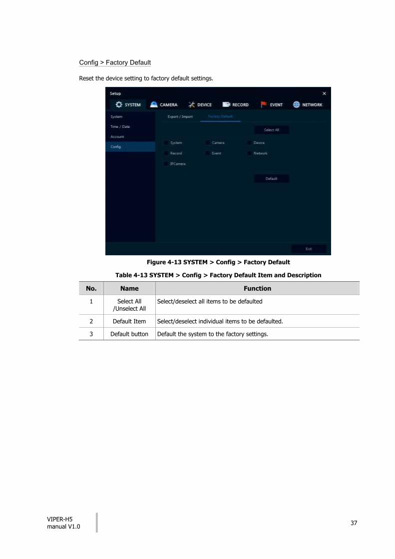
Config > Factory Default
Reset the device setting to factory default settings.
Figure 4-13 SYSTEM > Config > Factory Default
Table 4-13 SYSTEM > Config > Factory Default Item and Description
No. Name Function
1 Select All /Unselect All
Select/deselect all items to be defaulted
2 Default Item Select/deselect individual items to be defaulted.
3 Default button Default the system to the factory settings.

VIPER-H5 manual V1.0
38
4.3 CAMERA
Setup the camera configuration of each individual camera
4.3.1 Basic
Basic > Basic
Figure 4-14 CAMERA > Basic > Basic
Table 4-14 CAMERA > Basic > Basic Item and Description
No. Name Function
1 CH Shows the channel number
2 Title Edit the camera name.
3 Convert Select the cameras to be set in covert mode
4 Copy Covert Setup
Copy covert settings to other channels.

VIPER-H5 manual V1.0
39
Press Copy Covert Setup button, then Copy Covert Setup screen displays.
Figure 4-15 CAMERA > Basic > Basic > Copy Covert Setup
Table 4-15 CAMERA > Basic > Basic > Copy Covert Setup Item and Description
No. Name Function
1 From Select a channel to copy settings from
2 To Select a channels to be copied too.
3 Select All /Unselect All
Select/deselect all channels.

VIPER-H5 manual V1.0
40
Basic > Audio In
Figure 4-16 CAMERA >Basic > Audio In/Out
Table 4-16 CAMERA > Basic > Audio In/Out Item and Description
No. Name Function
1 No Display channel number
2 Use Select/deselect whether to use audio.
3 Assign Select channels to be assigned audio.
4 Record Select/deselect whether to record audio.
VIPER-H5 manual V1.0
41
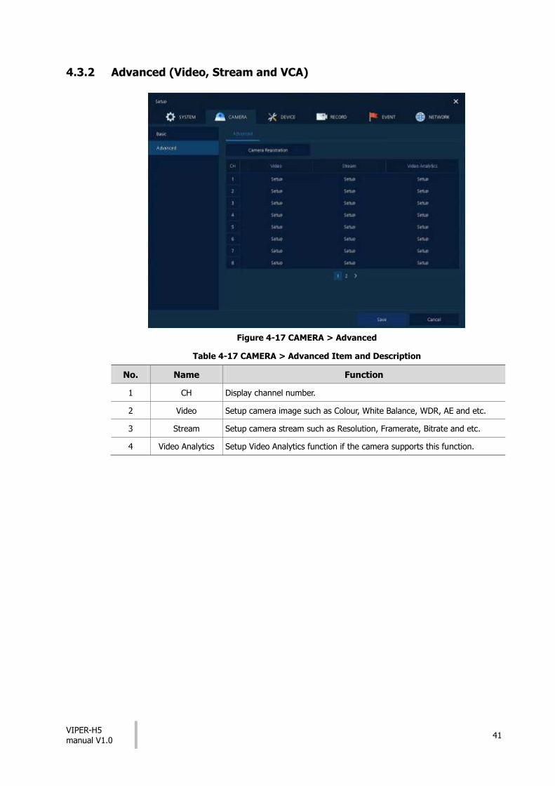
4.3.2 Advanced (Video, Stream and VCA)
Figure 4-17 CAMERA > Advanced
Table 4-17 CAMERA > Advanced Item and Description
No. Name Function
1 CH Display channel number.
2 Video Setup camera image such as Colour, White Balance, WDR, AE and etc.
3 Stream Setup camera stream such as Resolution, Framerate, Bitrate and etc.
4 Video Analytics Setup Video Analytics function if the camera supports this function.
VIPER-H5 manual V1.0
42
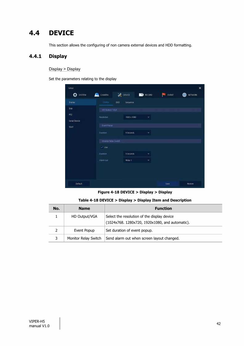
4.4 DEVICE
This section allows the configuring of non camera external devices and HDD formatting.
4.4.1 Display
Display > Display
Set the parameters relating to the display
Figure 4-18 DEVICE > Display > Display
Table 4-18 DEVICE > Display > Display Item and Description
No. Name Function
1 HD Output/VGA Select the resolution of the display device
(1024x768. 1280x720, 1920x1080, and automatic).
2 Event Popup Set duration of event popup.
3 Monitor Relay Switch Send alarm out when screen layout changed.

VIPER-H5 manual V1.0
43
Display > OSD
Set the OSD of the display device.
Figure 4-19 DEVICE > Display > OSD
Table 4-19 DEVICE > Display > OSD Item and Description
No. Name Function
1 Camera Name Select what is displayed in the camera titles (Off, CH+Title, CH).
2 Live Bar Select the way to display the live bar (Always On, Auto Hide).
3 Display Icon Select/deselect the icons to be displayed on each camera split screen segment.

VIPER-H5 manual V1.0
44
Display > Sequence
Figure 4-20 DEVICE > Display > Sequence
Table 4-20 DEVICE > Display > Sequence Item and Description
No. Name Function
1 Quad Sequence Set to convert automatically as 4-partition screen on the time basis.
2 Division Select screen partition mode to be marked in the below table (All, Full, and Quad).
3 Sequence List Display the sequence list based on division selected value.
4 Add Sequence Add items to be included in the play sequence.
5 NO Automatically controvert screens in number order.
6 Division Displays as full, 2X2 (Quad).
7 CH List Set automatic conversion CHs. In case of choosing CH3 in No. 1, CH3 is shown in advance.
8 Dwell Time Set the remaining time for automatic conversion (3 sec~30 sec)
9 Default Reverse to changed set value in default.
10 Revise the list.
11 Delete the list.

VIPER-H5 manual V1.0
45
Clicking Add Sequence displays Add Sequence screen.
Figure 4-21 DEVICE > Display > Sequence > Add Sequence
Table 4-21 DEVICE > Display > Sequence > Add Sequence Item and Description
No. Name Function
1 Dwell Time Select time to play (3 sec, 5 sec, 10 sec, 15 sec, and 30 sec).
2 Division Select the partition screen to play (Full, Quad).
3 Channel Selection Select channels to play.

VIPER-H5 manual V1.0
46
4.4.2 Disk > Setup
Disk > Setup
Figure 4-22 DEVICE > Disk > Setup
Table 4-22 DEVICE > Disk > Setup Item and Description
No. Name Function
1 Refresh disk information.
2 Disk Info Display the basic disk information in disc list.
Model: disk model name
Free: disk capacity to save
Size (Capacity): total disk capacity
Status: disk status
3 Rec. Info Display saved disk information in disc list.
Start Recording Time: starting time for saving information in the disk
End Recording Time: ending time to stop saving information in the disk
Status: disk status
4 S.M.A.R.T. Display S.M.A.R.T. information in disc list.
Model: disk model name
Temp.: disk temperature
Alive Time: running time after turning on the disk
S.M.A.R.T.: shows possible disk faults
5 Disk List Display the disk list select/deselect disc to be formatted
6 Format Format the disk selected.
7 Overwrite Recording
When the disks are full it will automatically overwrite the oldest information.
8 Auto Delete Select/deselect to use the function to delete saved data automatically (1-365 days).
VIPER-H5 manual V1.0
47
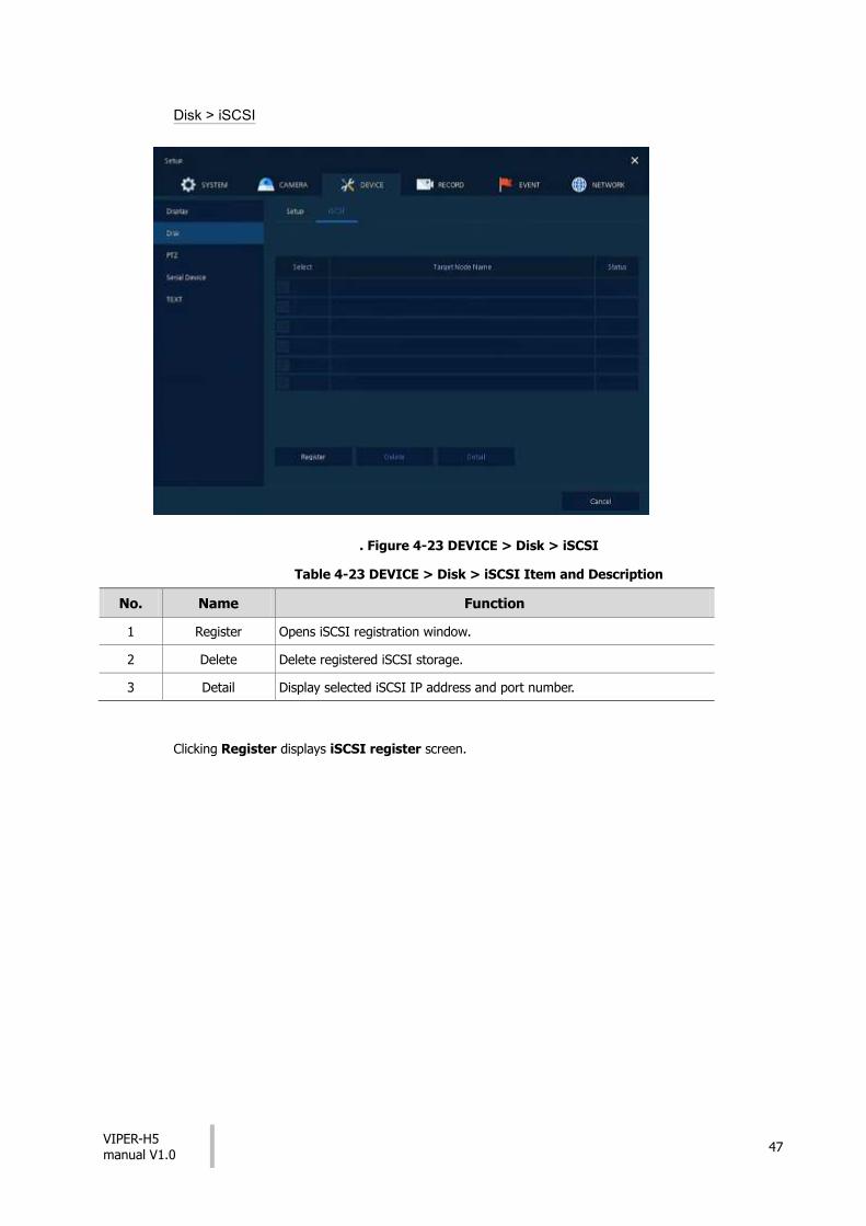
Disk > iSCSI
. Figure 4-23 DEVICE > Disk > iSCSI
Table 4-23 DEVICE > Disk > iSCSI Item and Description
No. Name Function
1 Register Opens iSCSI registration window.
2 Delete Delete registered iSCSI storage.
3 Detail Display selected iSCSI IP address and port number.
Clicking Register displays iSCSI register screen.

VIPER-H5 manual V1.0
48
No. Name Function
1 Target Address
Target Port
HTTP Port
Input IP address and ports for iSCSI
2 Discover Click to search iSCSI storage.
3 Add Click to register the discovered iSCSI storage.

VIPER-H5 manual V1.0
49
4.4.3 PTZ > PTZ
To use PTZ Function of the device, users need to match ID, protocol, and speed with each camera.
Figure 4-24 DEVICE > PTZ > PTZ
Table 4-24 DEVICE > PTZ > PTZ Item and Description
No. Name Function
1 Copy PTZ Setup Apply setting history to all or selected channels in the same way.
2 CH Display channels.
3 ID Select camera ID connected to relevant channels (1-255).
4 Protocol Select protocol of camera connected to relevant channels.
5 Speed Select pan-tilt of camera connected to relevant channels (1-5).
Note For more information about camera ID, protocol information, and details, see
Instruction of relevant PTZ Function camera.

VIPER-H5 manual V1.0
50
4.4.4 Serial Device > Serial Device (PTZ, keyboard, or Text device)
Figure 4-25 DEVICE > Serial Device > Serial Device
Table 4-25 DEVICE > Serial Device > Serial Device Item and Description
No. Name Function
1 USB (to Serial) Set communication transmission value of USB device.
2 RS-485 Set communication transmission value of RS-485 connector.
Set the communication transmission value based on the device to be connected and select the medium (PTZ, keyboard, or Text device).

VIPER-H5 manual V1.0
51
4.4.5 TEXT > TEXT
Used to configure PoS and Text devices to the DVR (Example - AVE VSI-PRO Max till interface)
Figure 4-26 DEVICE > TEXT > TEXT
Table 4-26 DEVICE > TEXT > TEXT Item and Description
No. Name Function
1 Use Select/deselect whether to use text function.
2 CH Select camera channels to connect with the text input device.
3 Protocol Select protocol to correspond with the text input device.
4 ID. Port Select ID and port no. to correspond with the text input device.
5 Input Char. Set Select a character format of the text input device.
6 Copy to TEXT Setup
As for connecting multiple units, duplicate set value to others.

VIPER-H5 manual V1.0
52
Press Copy to TEXT Setup button, then Copy to TEXT Setup screen displays.
Figure 4-27 DEVICE > TEXT > TEXT > Copy to TEXT Setup
Table 4-27 ICE > TEXT > TEXT > Copy to TEXT Setup Item and Description
No. Name Function
1 From Select channels set.
2 To Select the device to be copied.
3 Select All /Unselect All
Select/deselect all channels.
4 Copy Item Select/deselect items to be copied.

VIPER-H5 manual V1.0
53
4.5 RECORD
4.5.1 Schedule > Schedule
Each hour within each day can be allocated a different recording type
Figure 4-28 RECORD > Schedule > Schedule
Table 4-28 RECORD > Schedule > Schedule Item and Description
No. Name Function
1 CH Select channels to set schedules.
2 Schedule Type Selection
Select the types of schedules.
3 Schedule Table Display the schedule users set.
4 Drag Field Display the area dragged with a mouse.
5 Copy Schedule Setup Copy set recording schedule to other channels.

VIPER-H5 manual V1.0
54
The function of each scheduling type involves:
Table 4-29 Function of each scheduling type
Color Scheduling type Function
None Do not record.
Continuous Record on consecutive mode when time set.
Motion Record on event recording mode when motion sensitive event occurs.
Alarm Record on event recording mode when alarm occurs.
C+M Record on event recording mode when motion sensitive event occurs
during consecutive mode recording.
C+A Record on event recording mode when alarm occurs during consecutive mode recording.
M+A Record on event recording mode when only alarm and motion sensitive event occur.
C+M+A Record on event recording mode when only alarm and motion sensitive event occur during consecutive mode recording.
The way to schedule recording across channels
1 Select channels to schedule.
2 Select items in scheduling types.
3 Position the mouse to the schedule table.
4 Drag the area to be scheduled with a mouse.
5 Selected field is presented as scheduling type colors.
6 Click Copy Schedule Setup if you want to copy the schedule to other channels.

VIPER-H5 manual V1.0
55
7 Copy Schedule Setup screen displays.
8 Select channels to be copied.
9 Select channels to apply copied content.
10 Copy the schedule by pressing Apply.
11 Press Save to save the schedule.

VIPER-H5 manual V1.0
56
4.5.2 Stream
To set the image resolution when event occurs across channels or general recording is in process.
Stream > Main Stream
To set the image quality and resolution of Main Stream
Figure 4-29 RECORD > Stream > Main Stream
Table 4-30 RECORD > Stream > Main Stream Item and Description
No. Name Function
1 CH Display channels.
2 Resolution
Framerate
Bitrate
Show camera main stream setup status.
3 Continuous Select recording stream for Continuous mode.
4 Event Select recording stream for Event mode.
5 Pre-Alarm Start recording before set time, if event occurs (null, 1 sec, 2 sec, 3 sec, 4 sec, and 5 sec).
6 Post-Alarm Recording after set time until event ends (null, 5 sec, 10 sec, 30 sec, 1 min, 5 min, and 10 min).
7 Copy Stream Setup
Copy main recording image set value to other channels.

VIPER-H5 manual V1.0
57
Clicking Copy Stream Setup opens Copy Stream Setup.
Figure 4-30 RECORD > Stream > Main Stream > Copy Stream Setup
Table 4-31 RECORD > Stream > Main Stream > Copy Stream Setup Item and Description
No. Name Function
1 From Select the channel set.
2 To Select the device to be copied.
3 Select All
/Unselect All Select/deselect all channels.
4 Copy Item Select/deselect items to be copied.
VIPER-H5 manual V1.0
58
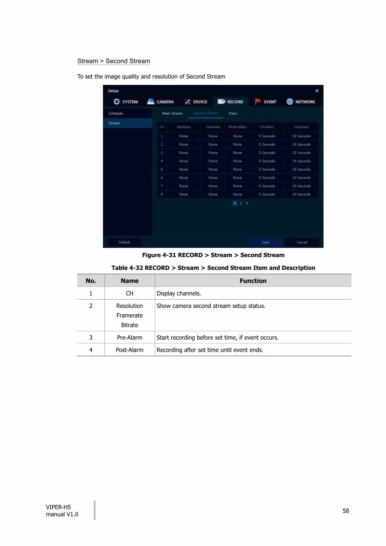
Stream > Second Stream
To set the image quality and resolution of Second Stream
Figure 4-31 RECORD > Stream > Second Stream
Table 4-32 RECORD > Stream > Second Stream Item and Description
No. Name Function
1 CH Display channels.
2 Resolution
Framerate
Bitrate
Show camera second stream setup status.
3 Pre-Alarm Start recording before set time, if event occurs.
4 Post-Alarm Recording after set time until event ends.

VIPER-H5 manual V1.0
59
Stream > Panic
Figure 4-32 RECORD > Stream > Panic
Table 4-33 RECORD > Stream > Panic Item and Description
No. Name Function
1 Panic Record Select/deselect to use immediate recording function.
2 CH Display channels.
3 Resolution
Frame rate
Quality
Panic recording stream follows the Event stream.
4 Dwell Time Select recording duration (No limits, 10 sec, 30 sec, 1 min, 5 min, 10 min, and 30 min).

VIPER-H5 manual V1.0
60
4.6 EVENT
4.6.1 System/Disk
System/Disk > System
Used to set up general system events and the actions that occur.
Figure 4-33 Event > System/Disk > System
Table 4-34 Event > System/Disk > System Item and Description
No. Name Function
1 System Restart Select/deselect whether to use system restart event.
2 Notification Select/deselect whether to use mailing in case of an event.
3 User Login Select/deselect whether to use when a user logs in
4 Record Transaction Select/deselect whether to use record transaction event occurs.

VIPER-H5 manual V1.0
61
System/Disk > Disk
To set disk event
Figure 4-34 Event > System/Disk > Disk
Table 4-35 Event > System/Disk > Disk Item and Description
No. Name Function
1 Disk Unplugged Select/deselect whether to use disk unplugged event
2 Beep Select/deselect whether to use buzzer sound in case of event.
3 Alarm out Select to end alarm time (null, Relay1-Keep, 5 sec, 10 sec, 20 sec, 30 sec, 1 min, 10 min, 30 min, and 1 hour).
4 Notification Select/deselect whether to use mailing in case of event.
5 Disk Full Set disk capacity for disk full event (Off, 50%, 60%, 70%, 80%, 90%, and 100%).
6 S.M.A.R.T. Fault Select/deselect whether to use S.M.A.R.T. Fault event of HDD.
VIPER-H5 manual V1.0
62
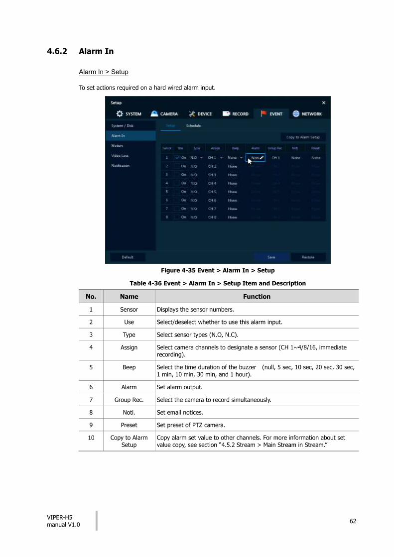
4.6.2 Alarm In
Alarm In > Setup
To set actions required on a hard wired alarm input.
Figure 4-35 Event > Alarm In > Setup
Table 4-36 Event > Alarm In > Setup Item and Description
No. Name Function
1 Sensor Displays the sensor numbers.
2 Use Select/deselect whether to use this alarm input.
3 Type Select sensor types (N.O, N.C).
4 Assign Select camera channels to designate a sensor (CH 1~4/8/16, immediate recording).
5 Beep Select the time duration of the buzzer (null, 5 sec, 10 sec, 20 sec, 30 sec,
1 min, 10 min, 30 min, and 1 hour).
6 Alarm Set alarm output.
7 Group Rec. Select the camera to record simultaneously.
8 Noti. Set email notices.
9 Preset Set preset of PTZ camera.
10 Copy to Alarm Setup
Copy alarm set value to other channels. For more information about set value copy, see section “4.5.2 Stream > Main Stream in Stream.”

VIPER-H5 manual V1.0
63
Placing your mouse on Alarm, Group Rec, Noti.or Preset and clicking editing Icon( ) in right
corner displays Event : Alarm screen.
Figure 4-36 Event > Alarm In > Setup > Event : Alarm
Table 4-37 Event > Alarm In > Setup > Event : Alarm Item and Description
No. Name Function
1 Alarm-out Set the alarm.
Relay: Select/clear the Relay output checkbox.
Dwell Time: Selecting alarm duration (Keep, 5 sec, 10 sec, 20 sec, 30 sec, 1 min, 10 min, 30 min, and 1 hour)
2 Group Recording Select/deselect whether to use Group Recording.
3 Simultaneous recording camera channel screen opens.
4 Monitor Popup Select/deselect whether to use Monitor Popup
5 Channel selection screen opens.
6 Remote Notification
Select/deselect whether to use remote mailing or Push.
7 Preset Preset of PTZ camera is running.
Use: Select/deselect whether to use preset.
CH: Select channels.
Preset: Set preset value.
VIPER-H5 manual V1.0
64
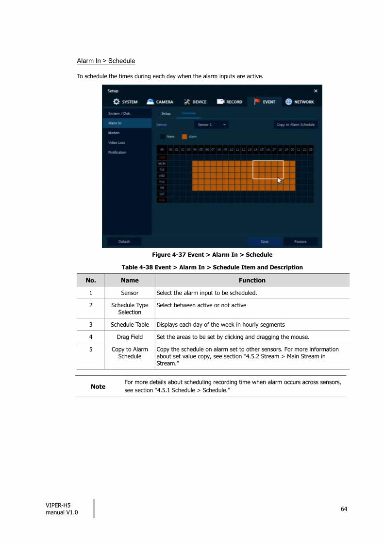
Alarm In > Schedule
To schedule the times during each day when the alarm inputs are active.
Figure 4-37 Event > Alarm In > Schedule
Table 4-38 Event > Alarm In > Schedule Item and Description
No. Name Function
1 Sensor Select the alarm input to be scheduled.
2 Schedule Type Selection
Select between active or not active
3 Schedule Table Displays each day of the week in hourly segments
4 Drag Field Set the areas to be set by clicking and dragging the mouse.
5 Copy to Alarm Schedule
Copy the schedule on alarm set to other sensors. For more information about set value copy, see section “4.5.2 Stream > Main Stream in Stream.”
Note For more details about scheduling recording time when alarm occurs across sensors,
see section “4.5.1 Schedule > Schedule.”

VIPER-H5 manual V1.0
65
4.6.3 Motion
Motion > Setup
Figure 4-38 Event > Motion > Setup
Table 4-39 Event > Motion > Setup Item and Description
No. Name Function
1 CH Display channels.
2 Use Select/deselect whether to use motion function in the channel.
3 Area Display the motion area.
4 Sens. Select the sense level of the motion sensor (Level 1~10).
5 Beep Select the duration of the buzzer (null, 5 sec, 10 sec, 20 sec, 30 sec, 1 min, 10 min, 30 min, and 1 hour).
6 Alarm Set alarm output.
7 Group Rec. Select the camera to record simultaneously.
8 Noti. Set email notices.
9 Preset Set preset of PTZ camera.
10 Copy to Motion Setup
Copy motion set value to other channels. For more information about set value copy, see section “4.5.2 Stream > Main Stream in Stream.”
Note
Placing your mouse on Alarm, Group Rec, Noti. or Preset and clicking editing
icon( ) in right corner displays Event : Alarm screen. For more information about
Event : Motion screen, see section “4.6.2 Alarm In > Setup in Alarm In.”

VIPER-H5 manual V1.0
66
Motion > Schedule
To schedule the record times when the motion detection is active on each channel.
Figure 4-39 Event > Motion > Schedule
Table 4-40 Event > Motion > Schedule Item and Description
No. Name Function
1 CH Select channels to set schedules.
2 Schedule Type Selection
Select the types of schedules.
3 Schedule Table Display the schedule users set.
4 Drag Field Display the area dragged with a mouse.
5 Copy to Motion Schedule
Copy the motion detection schedule to other channels. For more
information about set value copy, see section “4.5.2 Stream > Main
Stream in Stream.”
Note For more information how to schedule record time when the motion sensor detects
across channels, see section “4.5.1 Schedule > Schedule.”

VIPER-H5 manual V1.0
67
4.6.4 Video Loss > Setup
Figure 4-40 Event > Video Loss > Setup
Table 4-41 Event > Video Loss > Setup Item and Description
No. Name Function
1 CH Display channels.
2 Use Select/deselect whether to use Video Loss in the channel.
3 Beep Select use time of buzzer sound (null, 5 sec, 10 sec, 20 sec, 30 sec, 1 min, 10 min, 30 min, and 1 hour).
4 Alarm Set alarm output.
5 Group Rec. Select the camera to record simultaneously.
6 Noti. Set email notices.
7 Preset Set preset of PTZ camera.
8 Copy to Video Loss Setup
Copy the Video Loss set value to other channels. For more information
about set value copy, see section “4.5.2 Stream > Main Stream in
Stream.”
Note
Placing your mouse on Alarm, Group Rec, Noti., Preset and clicking editing
icon( ) in right corner displays Event : Video Loss screen. For more information
about Event : Video Loss screen, see section “4.6.2 Alarm In > Setup in Alarm In.”

VIPER-H5 manual V1.0
68
4.6.5 Notification
To set and schedule periodical alarms
Notification > Periodic
Figure 4-41 EVENT > Notification > Periodic
Table 4-42 EVENT > Notification > Periodic Item and Description
No. Name Function
1 Periodic Notification
Select/deselect whether to use periodical alarms
2 Summary Send the save or event information.
Record: sending the save information
Event: sending the event information
3 Interval Set the alarm interval (5 min, 10 min, 30 min, and 1 hour, 2-hour, 6-hour,
8-hour, 12-hour, and 24-hour).
4 Select CH Select channels users want.
5 Select All /Unselect All
Select/deselect all channels
VIPER-H5 manual V1.0
69
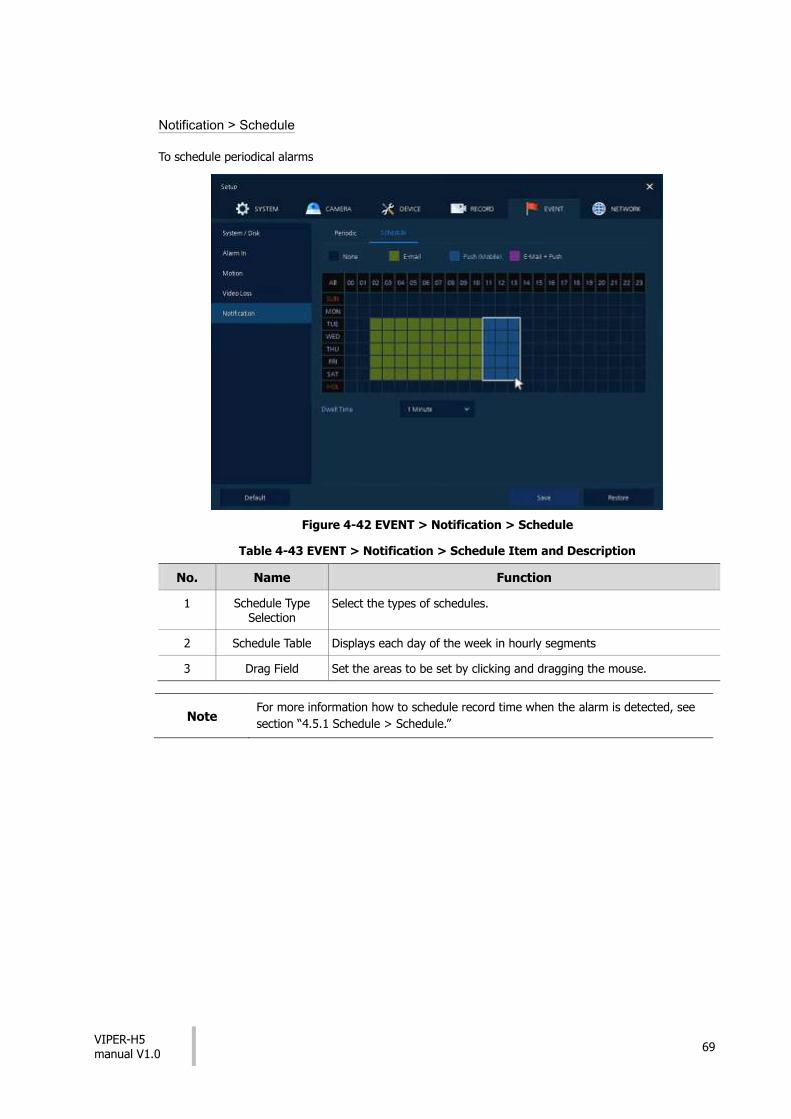
Notification > Schedule
To schedule periodical alarms
Figure 4-42 EVENT > Notification > Schedule
Table 4-43 EVENT > Notification > Schedule Item and Description
No. Name Function
1 Schedule Type Selection
Select the types of schedules.
2 Schedule Table Displays each day of the week in hourly segments
3 Drag Field Set the areas to be set by clicking and dragging the mouse.
Note For more information how to schedule record time when the alarm is detected, see
section “4.5.1 Schedule > Schedule.”

VIPER-H5 manual V1.0
70
4.7 NETWORK
4.7.1 Basic
BASIC > WAN Port
Figure 4-43 NETWORK > Basic > WAN Port
Table 4-44 NETWORK > Basic > WAN Port Item and Description
No. Name Function
1 Static IP Check if you use static IP. For using static IP, enter IP address, Subnet Mask, and Gateway.
2 DHCP (Dynamic) Select whether to use DHCP (Dynamic).
3 MAC Address Displays the MAC Address of the DVR.
4 DNS Select manual and enter DNS; otherwise choose automatic function.
5 Port (TCP) Enter TCP port.
6 Port (Web) Enter Web port.
7 Bandwidth Limit Select bandwidth to limit (no limits, 50Mbps, 10Mbps, 5Mbps, 2Mbps, 1Mbps, 500Kbps, 400Kbps, 300Kbps, 200Kbps, and 100Kbps).
8 Ping Test Enter IP in Ping test and click “Test”.

VIPER-H5 manual V1.0
71
Basic > PoE Ports
To set the network PoE Ports
Figure 4-44 NETWORK > Basic > PoE Ports
Table 4-45 NETWORK > Basic > PoE Ports Item and Description
No. Name Function
1 DHCP Server Select whether to enable DHCP server.
2 DHCP (Dynamic) Select whether to use DHCP (Dynamic).
3 IP Address
Subnet Mask
Gateway
Enter the each information properly.

VIPER-H5 manual V1.0
72
4.7.2 DVRNS/DDNS
DVRNS/DDNS > DVRNS/Dashboard
This allows the user to register all their VIPER devices on a remote server under a unique account. They can then login into the server to view: Live images; Set up the devices and view the status of each device.
Figure 4-45 NETWORK > DVRNS/DDNS > DVRNS/Dashboard
Table 4-46 NETWORK > DVRNS/DDNS > DVRNS/Dashboard Item and Description
No. Name Function
1 DVRNS Register DVRNS account
ID: Enter DVRNS ID (default: MAC address of the unit)
Password: Enter DVRNS password
Register: Register DVRNS account
2 Dashboard Add/delete Dashboard account
Account: Select the types of account (Existing Account or New Account)
ID: Enter Dashboard ID
Password: Enter Dashboard password
Add Device: Add Dashboard account
Delete Device: Delete Dashboard account
VIPER-H5 manual V1.0
73
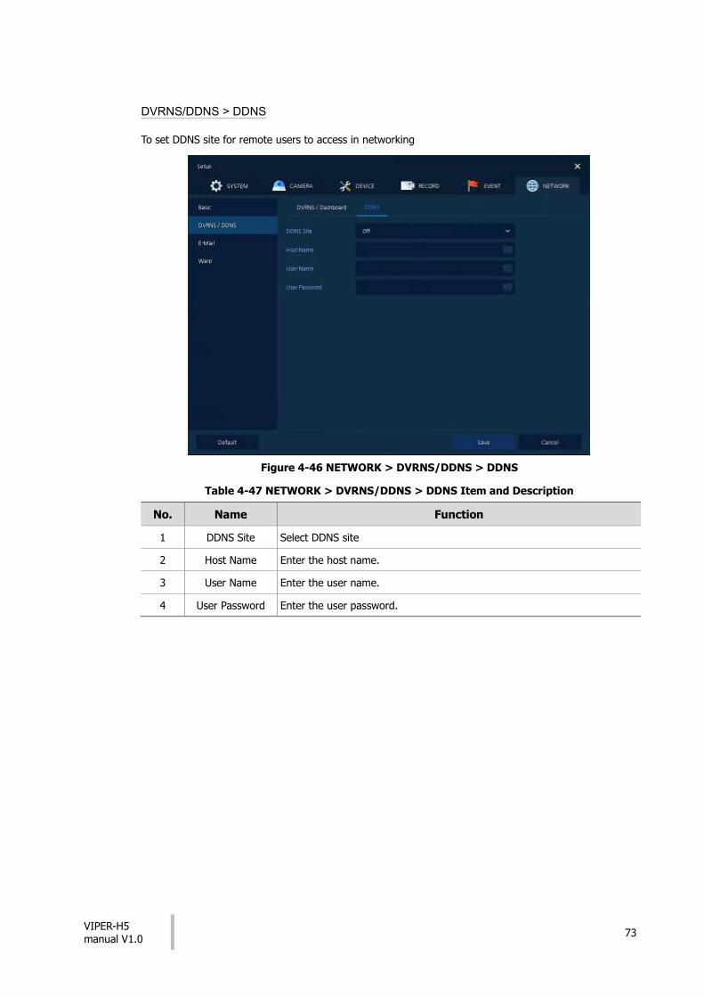
DVRNS/DDNS > DDNS
To set DDNS site for remote users to access in networking
Figure 4-46 NETWORK > DVRNS/DDNS > DDNS
Table 4-47 NETWORK > DVRNS/DDNS > DDNS Item and Description
No. Name Function
1 DDNS Site Select DDNS site
2 Host Name Enter the host name.
3 User Name Enter the user name.
4 User Password Enter the user password.
VIPER-H5 manual V1.0
74
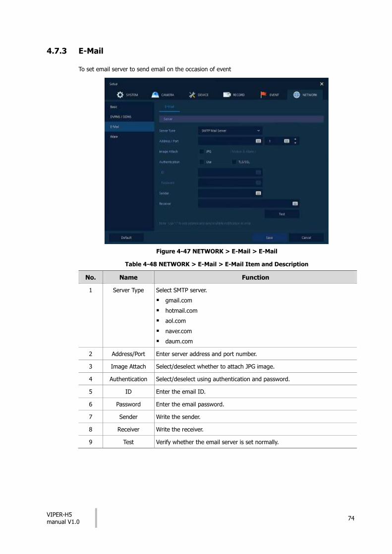
4.7.3 E-Mail
To set email server to send email on the occasion of event
Figure 4-47 NETWORK > E-Mail > E-Mail
Table 4-48 NETWORK > E-Mail > E-Mail Item and Description
No. Name Function
1 Server Type Select SMTP server.
gmail.com
hotmail.com
aol.com
naver.com
daum.com
2 Address/Port Enter server address and port number.
3 Image Attach Select/deselect whether to attach JPG image.
4 Authentication Select/deselect using authentication and password.
5 ID Enter the email ID.
6 Password Enter the email password.
7 Sender Write the sender.
8 Receiver Write the receiver.
9 Test Verify whether the email server is set normally.
VIPER-H5 manual V1.0
75
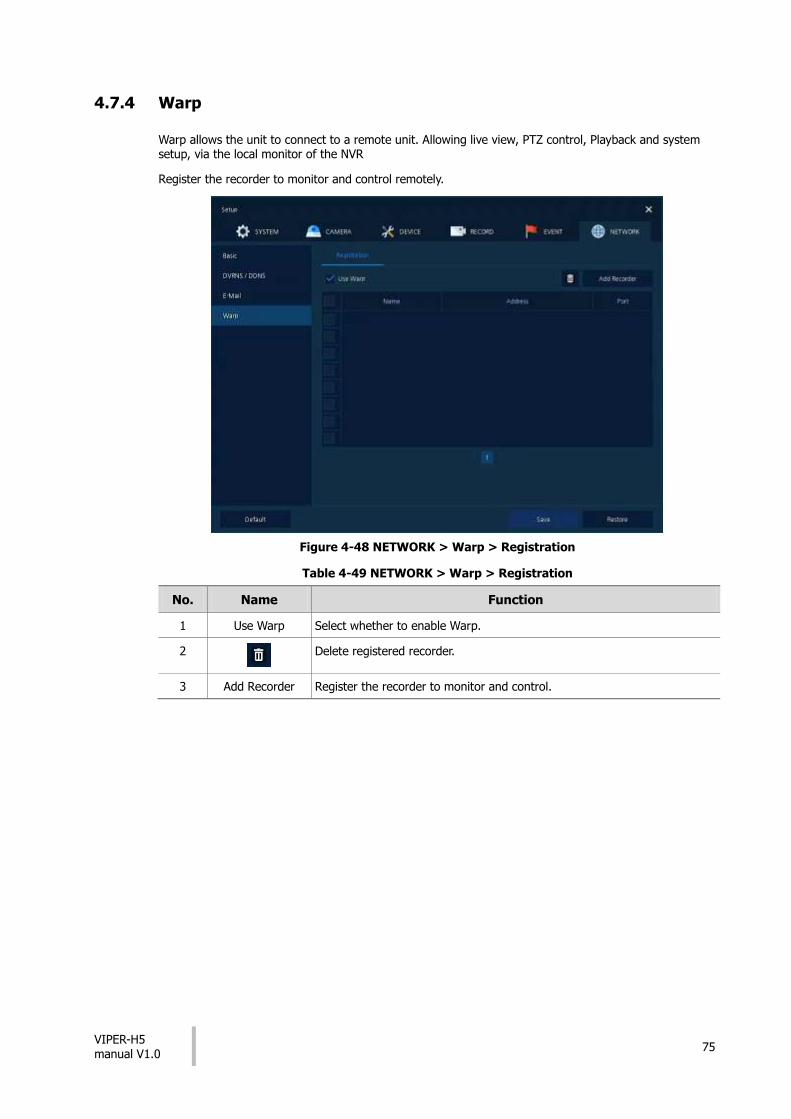
4.7.4 Warp
Warp allows the unit to connect to a remote unit. Allowing live view, PTZ control, Playback and system setup, via the local monitor of the NVR
Register the recorder to monitor and control remotely.
Figure 4-48 NETWORK > Warp > Registration
Table 4-49 NETWORK > Warp > Registration
No. Name Function
1 Use Warp Select whether to enable Warp.
2 Delete registered recorder.
3 Add Recorder Register the recorder to monitor and control.

VIPER-H5 manual V1.0
76
5. Search/Play
This chapter describes Live Launcher search and play menu located at the bottom of the screen.
Figure 5-1 Live Launcher Search, Play menu
Table 5-1 Item and Description of Live Launcher Search, Play menu
No. Item Description
1 Searching recording data (time, event, and thumbnail).
2 Playing recorded data – go direct to playback mode.
5.1 Search
This function allows searching of recorded data via various methods: Time, Event, Thumbnail, Smart Search and Text.
Figure 5-2 Search: Time
Table 5-2 Search: Time Item and Description
No. Item Description
1 Calendar Select the date to be searched
2 Time Set the time to be viewed
3 Bookmark Select any pre-defined bookmarks
4 Timeline Displays the timelines across channels
5 Preview Previewing video clips searched
6 Play Playing video clips. For more information about Live bar, see section “5.2
Playback.”
7 Cancel Exit the search screen
VIPER-H5 manual V1.0
77
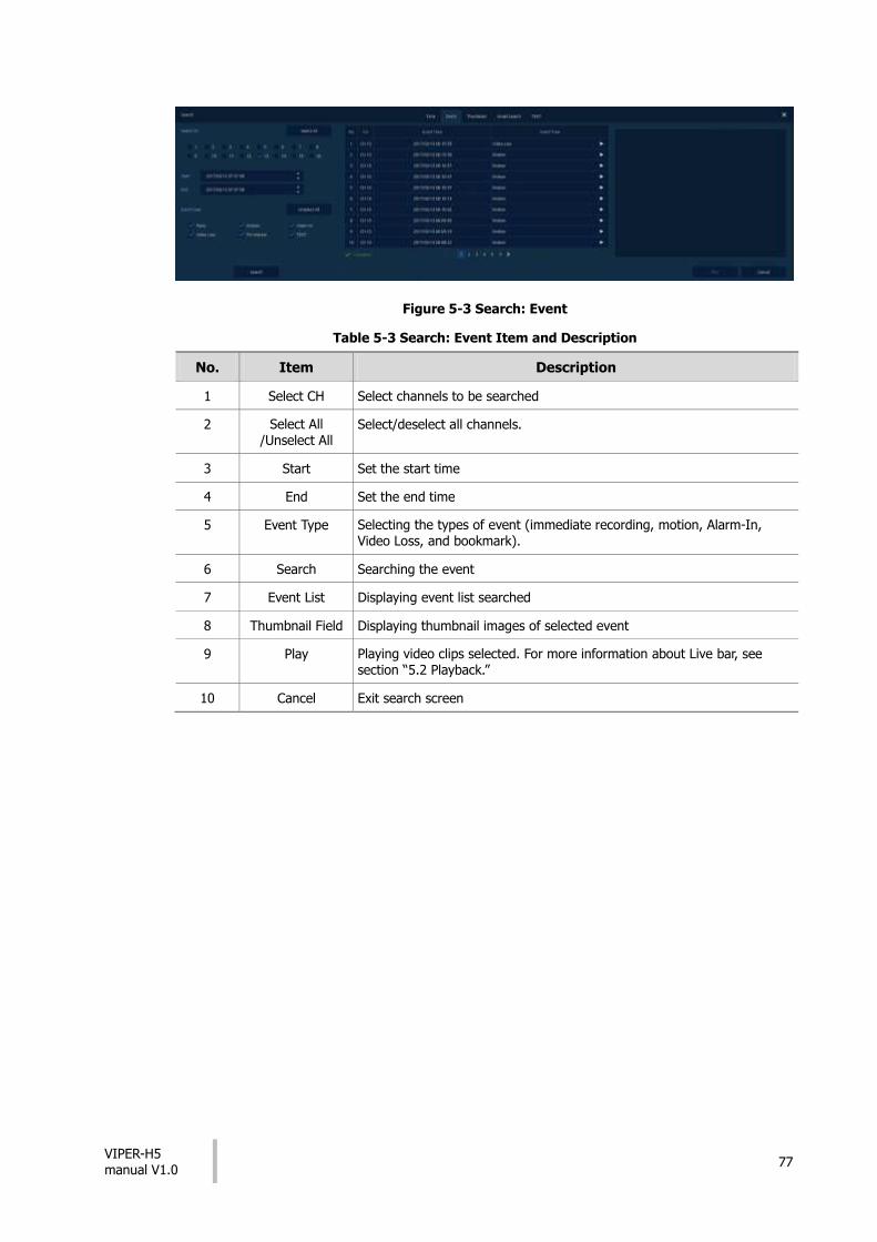
Figure 5-3 Search: Event
Table 5-3 Search: Event Item and Description
No. Item Description
1 Select CH Select channels to be searched
2 Select All /Unselect All
Select/deselect all channels.
3 Start Set the start time
4 End Set the end time
5 Event Type Selecting the types of event (immediate recording, motion, Alarm-In, Video Loss, and bookmark).
6 Search Searching the event
7 Event List Displaying event list searched
8 Thumbnail Field Displaying thumbnail images of selected event
9 Play Playing video clips selected. For more information about Live bar, see section “5.2 Playback.”
10 Cancel Exit search screen

VIPER-H5 manual V1.0
78
Figure 5-4 Search: Thumbnail
Table 5-4 Search: Thumbnail Item and Description
No. Item Description
1 Calendar Select dates to search
2 CH Select channels to search
3 Time Select time to begin search
4 Interval Setting time interval between images to be displayed
5 Time Lapse/Pause
This plays each displayed segment forward in time lapse mode
10 Cancel Exit search screen

VIPER-H5 manual V1.0
79
Figure 5-5 Search: Smart Search
Table 5-5 Search: Smart Search Item and Description
No. Item Description
1 CH Selecting channels to search
2 Area Setup Set up the area of the screen in which analysis is to be carried out
3 Start Setting starting time to search
4 End Setting ending time to search (Note: Maximum period for search is limited to a one hour period)

VIPER-H5 manual V1.0
80
Figure 5-6 Search: Text
Table 5-6 Search: Text Item and Description
No. Item Description
1 Select CH Select channels to search
2 Select All /Unselect All
Select/deselect all channels.
3 Start Set the start time to search
4 End Set the end time to search
5 Keyword Entering keyword to search
6 Case Sensitive Searching items in case-sensitive
7 Whole Word Searching items that include all words
8 Search Click to start search
9 Event List Displaying event list searched
10 Thumbnail Field Displaying thumbnail images of selected event
11 Play Play the selected video clip. For more information about Live bar, see section “5.2 Playback.”
12 Cancel Exit search screen
VIPER-H5 manual V1.0
81
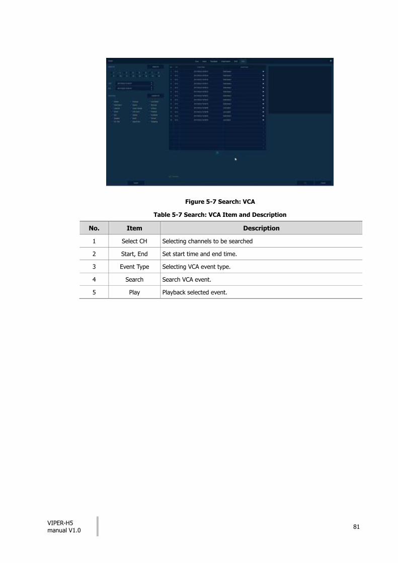
Figure 5-7 Search: VCA
Table 5-7 Search: VCA Item and Description
No. Item Description
1 Select CH Selecting channels to be searched
2 Start, End Set start time and end time.
3 Event Type Selecting VCA event type.
4 Search Search VCA event.
5 Play Playback selected event.

VIPER-H5 manual V1.0
82
5.2 Playback
To play recorded data
Figure 5-8 Playback Launcher
Table 5-8 Playback Launcher Item and Description
No. Item Description
1 Displays present play status
2 Date and Time Displaying date and time of video being played
3 Moving to the first section of the video
4 Playing the videos with multiplied speed in reverse (2~64x).
5 Playing the videos with lower speed in reverse (1/2~1/8x).
6 Play and Pause (toggle).
7 Play forward at slow speeds (1/2~1/8x).
8 Fast forward (2~64x).
9 Moving to previous/next channel or multi screen
10 Selecting the partition mode to mark in the screen
11 Searching the recorded data (time, event, and thumbnail). For more information about search, see section “5.1 Search.”
12 Go to Live mode
13 Opening or closing the record timelines
14 Activating/deactivating automatic hidden function of Launcher menu

VIPER-H5 manual V1.0
83
6. Webviewer
This chapter describes webviewer for monitoring videos through a PC in remote mode.
How to monitor with webviewer
Table 6-1 System Requirement for Webviewer
Item Recommended Minimum
OS MicrosoftⓇ WindowsⓇ 10 x86(64bit)
(Home Premium, Professional, Ultimate)
MicrosoftⓇ WindowsⓇ 8(pro, Enterprise)
MicrosoftⓇ WindowsⓇ XP Home SP3
CPU Intel CoreTM i5-2550 3.30GHz or higher Intel CoreTM 2 Duo E7200 2.53GHz or higher
RAM 2GB or higher 1.5GB or higher
VGA ATI RadeonTM HD 3650 or NVIDIA GeForce 8400GS or higher(1280x1024,
32bpp or Higher), Multi Monitor
ATI RadeonTM HD 2400 or NVIDIA GeForce FX5500 or higher(1024x768, 24bpp or higher)
HDD Over 6GB Over 1GB
LAN Gigabit Ethernet 10/100 Mbps Ethernet
1 Enter IP address of a recorder in
Internet browser.
2 Enter ID and Password, and then click the button.
Viewer: playing NVR Live images
Setup: setting menu in similar ways with NVR connected monitor.
Selecting Viewer
For using Viewer, users need to download Java. The way to download is shown as follows:
1 Click Viewer.

VIPER-H5 manual V1.0
84
2 When Java download screen opens, download and install JAVA.
3 Live images may be monitored.
Selecting Setup
Users can set the menu in similar ways with NVR connected monitor.
Figure 6-1 Setup screen

VIPER-H5 manual V1.0
85
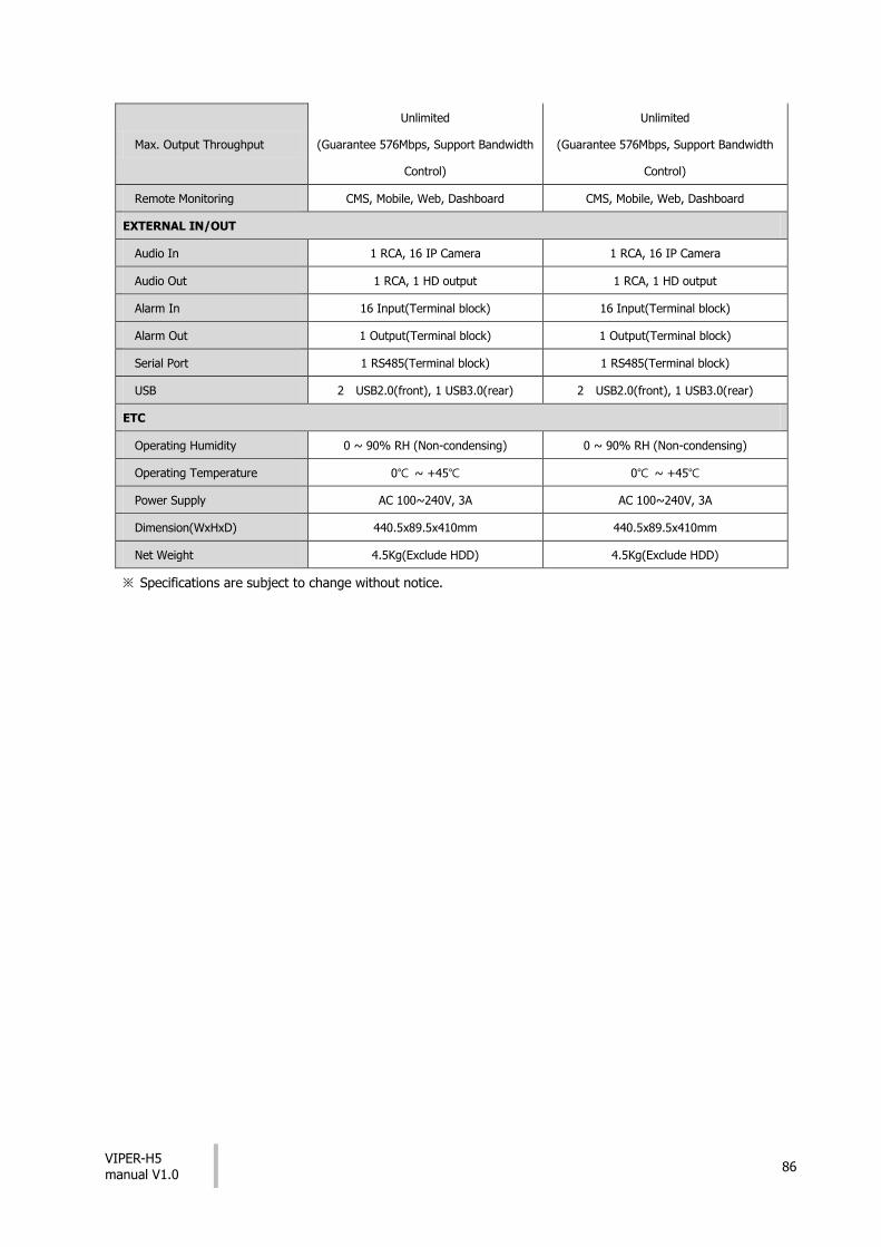
7. Products Specifications
Channel 16ch 32ch
VIDEO
Video Input 16 IP 32 IP
Video Input Resolution Up to 8MP Up to 8MP
Compression H.264, H.265 H.264, H.265
Display Output 1 VGA, 1 HD Output 1 VGA, 1 HD Output
Display Resolution 4K, 1920x1080, 1280x720, 1024x768 4K, 1920x1080, 1280x720, 1024x768
Display Speed 400/ 480fps 400/ 480fps
Display Mode 1/4//9/16 Split, PIP, Sequence 1/4//9/16/32 Split, PIP, Sequence
RECORDING
Recording Speed 400/480fps@8MP 800/960fps@8MP
Max. Recording Throughput 160Mbps 320Mbps
Recording Mode Continuous, Motion, Alarm, C+M, C+A,
M+A, C+M+A, Panic
Continuous, Motion, Alarm, C+M, C+A,
M+A, C+M+A, Panic
Pre Alarm 1sec ~ 5sec 1sec ~ 5sec
Post Alarm 5sec ~10Min 5sec ~10Min
PLAYBACK
Simultaneous Playback 1/4/9/16 Split 1/4/9/16/32 Split
Playback Mode Backward, Forward 2x~64x Backward, Forward 2x~64x
Search Mode Time, Event, Thumbnail, Text Time, Event, Thumbnail, Text
STORAGE
Internal HDD 4 SATA Interfaces 4 SATA Interfaces
External Storage iSCSI, 1 e-SATA iSCSI, 1 e-SATA
Backup USB USB
Backup File Format AVI, H4V AVI, H4V
FUNCTION
Text In POS/ATM(Network, RS485, USB) POS/ATM(Network, RS485, USB)
User Interface Mouse, USB/RS485 Keyboard Mouse, USB/RS485 Keyboard
NETWORK
Ethernet
WAN 1 RJ45 10/100/1000 Base-T 1 RJ45 10/100/1000 Base-T
PoE 16 RJ45 10/100 Base-T 16 RJ45 10/100 Base-T
PoE power 130W(IEEE802.3at compliance) 130W(IEEE802.3at compliance)
VIPER-H5 manual V1.0
86
Max. Output Throughput
Unlimited
(Guarantee 576Mbps, Support Bandwidth
Control)
Unlimited
(Guarantee 576Mbps, Support Bandwidth
Control)
Remote Monitoring CMS, Mobile, Web, Dashboard CMS, Mobile, Web, Dashboard
EXTERNAL IN/OUT
Audio In 1 RCA, 16 IP Camera 1 RCA, 16 IP Camera
Audio Out 1 RCA, 1 HD output 1 RCA, 1 HD output
Alarm In 16 Input(Terminal block) 16 Input(Terminal block)
Alarm Out 1 Output(Terminal block) 1 Output(Terminal block)
Serial Port 1 RS485(Terminal block) 1 RS485(Terminal block)
USB 2 USB2.0(front), 1 USB3.0(rear) 2 USB2.0(front), 1 USB3.0(rear)
ETC
Operating Humidity 0 ~ 90% RH (Non-condensing) 0 ~ 90% RH (Non-condensing)
Operating Temperature 0℃ ~ +45℃ 0℃ ~ +45℃
Power Supply AC 100~240V, 3A AC 100~240V, 3A
Dimension(WxHxD) 440.5x89.5x410mm 440.5x89.5x410mm
Net Weight 4.5Kg(Exclude HDD) 4.5Kg(Exclude HDD)
※ Specifications are subject to change without notice.

VIPER-H5 manual V1.0
87
Version 1.0
Norbain SD
210 Wharfedale Road
Winnersh Triangle
Wokingham
England
RG41 5TP
01189 125 000