H ybrid Þ nite-elem ent/m olecular-dynam ics/ electronic...
12
Computer Physics Communications 138 (2001) 143–154 www.elsevier.com/locate/cpc Hybrid finite-element/molecular-dynamics/ electronic-density-functional approach to materials simulations on parallel computers Shuji Ogata a , Elefterios Lidorikis b , Fuyuki Shimojo c , Aiichiro Nakano b,* , Priya Vashishta b , Rajiv K. Kalia b a Department of Applied Sciences, Yamaguchi University, Ube 755-8611, Japan b Concurrent Computing Laboratory for Materials Simulations, Louisiana State University, Baton Rouge, LA 70803-4001, USA c Faculty of Integrated Arts and Sciences, Hiroshima University, Higashi-Hiroshima 739-8521, Japan Received 15 December 2000; received in revised form 15 February 2001; accepted 1 March 2001 Abstract A hybrid simulation approach is developed to study chemical reactions coupled with long-range mechanical phenomena in materials. The finite-element method for continuum mechanics is coupled with the molecular dynamics method for an atomic system that embeds a cluster of atoms described quantum-mechanically with the electronic density-functional method based on real-space multigrids. The hybrid simulation approach is implemented on parallel computers using both task and spatial decompositions. Additive hybridization and unified finite-element/molecular-dynamics schemes allow scalable parallel implementation and rapid code development, respectively. A hybrid simulation of oxidation of Si(111) surface demonstrates seamless coupling of the continuum region with the classical and the quantum atomic regions. 2001 Elsevier Science B.V. All rights reserved. PACS: 82.20.Wt; 62.40.+i; 68.10.Jy Keywords: Hybrid simulation; Finite-element method; Density-functional theory; Molecular dynamics; Parallel computation 1. Introduction In recent years, various forms of nanostructured materials [1,2] such as nanoparticles, thin films, and nanophase materials have attracted much attention due to their improved mechanical, catalytic, and opto-electronic properties [3] resulting from their nanometer-size domains [1,3]. Understanding formation dynamics of nanostructured materials and their resulting unique physico-chemical properties requires accurate dynamic simulations of chemically reacting atoms in these materials. Highly accurate simulations based on energy density-functional theory (DFT) [4,5] for electronic structures have been used extensively to study chemical reactions in clusters * Corresponding author. E-mail address: [email protected] (A. Nakano). 0010-4655/01/$ – see front matter 2001 Elsevier Science B.V. All rights reserved. PII:S0010-4655(01)00203-X
-
Upload
phungduong -
Category
Documents
-
view
214 -
download
0
Transcript of H ybrid Þ nite-elem ent/m olecular-dynam ics/ electronic...
Computer Physics Communications 138 (2001) 143–154www.elsevier.com/locate/cpc
Hybrid finite-element/molecular-dynamics/electronic-density-functional approach to materials simulations
on parallel computersShuji Ogata a, Elefterios Lidorikis b, Fuyuki Shimojo c, Aiichiro Nakano b,!, Priya Vashishta b,
Rajiv K. Kalia ba Department of Applied Sciences, Yamaguchi University, Ube 755-8611, Japan
b Concurrent Computing Laboratory for Materials Simulations, Louisiana State University, Baton Rouge, LA 70803-4001, USAc Faculty of Integrated Arts and Sciences, Hiroshima University, Higashi-Hiroshima 739-8521, Japan
Received 15 December 2000; received in revised form 15 February 2001; accepted 1 March 2001
Abstract
A hybrid simulation approach is developed to study chemical reactions coupled with long-range mechanical phenomenain materials. The finite-element method for continuum mechanics is coupled with the molecular dynamics method for anatomic system that embeds a cluster of atoms described quantum-mechanically with the electronic density-functional methodbased on real-space multigrids. The hybrid simulation approach is implemented on parallel computers using both task andspatial decompositions. Additive hybridization and unified finite-element/molecular-dynamics schemes allow scalable parallelimplementation and rapid code development, respectively. A hybrid simulation of oxidation of Si(111) surface demonstratesseamless coupling of the continuum region with the classical and the quantum atomic regions. 2001 Elsevier Science B.V.All rights reserved.
PACS: 82.20.Wt; 62.40.+i; 68.10.Jy
Keywords: Hybrid simulation; Finite-element method; Density-functional theory; Molecular dynamics; Parallel computation
1. Introduction
In recent years, various forms of nanostructured materials [1,2] such as nanoparticles, thin films, and nanophasematerials have attracted much attention due to their improved mechanical, catalytic, and opto-electronic properties[3] resulting from their nanometer-size domains [1,3]. Understanding formation dynamics of nanostructuredmaterials and their resulting unique physico-chemical properties requires accurate dynamic simulations ofchemically reacting atoms in these materials. Highly accurate simulations based on energy density-functionaltheory (DFT) [4,5] for electronic structures have been used extensively to study chemical reactions in clusters
* Corresponding author.E-mail address: [email protected] (A. Nakano).
0010-4655/01/$ – see front matter 2001 Elsevier Science B.V. All rights reserved.PII: S0010-4655(01)00203-X

144 S. Ogata et al. / Computer Physics Communications 138 (2001) 143–154
of atoms [6]. Despite considerable progress in formulation, algorithms, and parallel computing techniques, DFT-based dynamic simulations are currently limited to systems containing less than a few hundred atoms dueto long computation times [7,8]. To overcome this limitation, we have recently developed a hybrid quantum-mechanical/molecular-dynamics (QM/MD) approach [9] to dynamic simulation of materials on parallel computers.The approach follows the idea on which hybrid quantum-mechanical/molecular-mechanics (QM/MM) methods[10–18] for geometrical optimization of large biological molecules are based: Computation can be made less whenwe partition a simulation system into different regions that are modeled with varying degrees of approximation.In the hybrid QM/MD approach, a QM system described by DFT based on real-space multigrids [8,9,19–24] isembedded in a classical system of atoms interacting via an empirical interatomic potential. Handshake atoms areintroduced to couple the quantum and the classical systems dynamically based on the scaled position method [9].The hybrid QM/MD approach enables dynamic simulations of material processes involving chemical reactionssuch as oxidation [9].There is growing demand for large-scale materials simulations involving chemical reactions, e.g., to study the
interplay between stress fields and chemical reactions. Stress in materials is long-ranged; it decays in proportionto the inverse-square-root of the distance from a crack [2,3]. Stress fields, which depend on the size and theoverall shape of the system, may affect local atomic diffusion rates and hence chemical reactions. There areattempts to fabricate three-dimensional patterns in opto-electronic devices by controlling local atomic-diffusionand oxidation rates through stress [25–28]. Large-scale dynamic simulations with realistic stress fields are expectedto play a key role in understanding atomistic mechanisms of these processes. Another example that requireslarge-scale simulations involving chemical reactions deals with micro-electro-mechanical systems (MEMS) [29],in which feature sizes are submicrons. Constitutive relations and scaling laws [2] in engineering mechanicshave not been validated at such small length scales, and consequently lifetime prediction of MEMS is currentlyimpractical [29]. Large-scale simulations involving chemical reactions will contribute significantly in this area byproviding atomistic understanding of environmental effects on fracture and fatigue processes in MEMS.Recent advances in algorithms and parallel computers have enabled MD simulations [30] involving 108"109
atoms with system sizes exceeding 0.1µm [31,32]. With the hybrid QM/MD approach [9], systems with similarsizes can be simulated in which 103"104 atoms are treated quantum-mechanically, using scalable DFT algorithms[8]. To simulate entire MEMS and device structures (> 1µm), however, it is necessary to coarse-grain atomicdetails in the peripheral region of the system. The coarse-graining can be achieved with the finite element (FE)method [33], in which a material is regarded as a continuum and is decomposed into a mesh of finite elements.Various handshake schemes have been proposed to couple the MD and the FE regions in hybrid FE/MD
simulations [34–39]. In one of the first attempts by Mullins and Dokainish [34], pseudo-atoms embedded infinite elements interact with the MD atoms through the MD interatomic potential. Kohlhoff, Gumbsch, andFischmeister [35] introduced a transition zone between the FE and the MD regions and scaled down the finite-element size to the atomic scale in the transition zone. Abraham et al. [36] further improved the FE/MD couplingby constructing an explicit Hamiltonian for the atoms and the FE nodes in the transition zone as an average of theMD and the FE Hamiltonians. The FE/MD approach has been applied to crack propagation in Si, in which QMcalculations based on the semi-empirical tight-binding method are coupled with the MD and the FE methods [36,37]. Lidorikis et al. [38] have extended the FE/MD approach and used it to study atomistically-induced stresses inSi/Si3N4 nanopixels.In this paper, we develop a hybrid FE/MD/QM approach to materials simulations on parallel computers by
combining the FE method with our hybrid QM/MDmethod [9] based on the FE/MD coupling scheme in Refs. [36–38]. Seamless coupling between the FE, MD and QM regions is demonstrated through a simulation run of oxidationof Si(111) surface. Sections 2 and 3 describe the present hybrid FE/MD/QM approach and its implementation onparallel computers, respectively. The parallel code is applied to oxidation of Si(111) surface in Section 4, andconcluding remarks are given in Section 5.

S. Ogata et al. / Computer Physics Communications 138 (2001) 143–154 145
2. Hybrid simulation scheme
In describing the present hybrid scheme, it is helpful to use the initial configuration of the hybrid simulation ofoxidation of Si(111) surface (see Section 4). Fig. 1(a) shows the decomposition of the system into FE, MD, andQM regions. The system is periodic in two horizontal directions, while free boundary conditions are applied in thevertical direction, i.e. [111]. In the FE method, the system is regarded as a continuum and is decomposed into amesh of finite elements. In Fig. 1(a), the FE mesh points (nodes) are plotted as magenta spheres, whereas the atomsare depicted as blue spheres. In the handshake (HS) region between the FE and the MD regions, the FE mesh is
Fig. 1. (a) Initial configuration of the hybrid simulation of oxidation of Si(111) surface. Magenta spheres represent FE nodes; yellow, FE/MD-HSatoms; blue, MD atoms; red, O atoms. (b) Close up view of the QM and the QM/MD-HS atoms. Yellow spheres represent Si atoms; red, O atoms;blue, handshake Si atoms; magenta, termination H atoms. Charge densities are shown in grayscale.

146 S. Ogata et al. / Computer Physics Communications 138 (2001) 143–154
refined down to the atomic scale in such a way that each FE node coincides with an MD atom [36–40]; yellowspheres in Fig. 1(a) represent these composite atoms/nodes constituting the FE/MD-HS region. The FE calculationsapply to the FE and the FE/MD-HS regions, whereas the MD calculations apply to the MD and the FE/MD-HSregions. Red spheres above the top Si(111) layer in Fig. 1(a) represent an O2 molecule. Fig. 1(b) shows the QMatoms as well as the HS atoms between the QM and the MD regions for the DFT calculations: red (O) and yellow(Si) spheres are the QM atoms, and blue spheres bonding to the yellow spheres represent the QM/MD-HS atoms.Magenta spheres in Fig. 1(b) correspond to virtual hydrogen atoms introduced in the DFT calculations to terminatedangling bonds of the QM atoms. Details of the termination scheme are described in Section 2.2.Fig. 2 shows two-dimensional views of the FE/MD-HS region and its surroundings from two different directions.
Hatched polygons with dots (nodes) at their corners or on their edges represent the finite elements. The finiteelements, which are either prismatic or rectangular, occupy the whole FE and FE/MD-HS regions by sharing theircorners or edges [38]. Total number of nodes in the finite element varies between 8 and 20 [38]. Twenty-nodeelements are used in the FE region far from the FE/MD-HS region, while eight-node elements are used close to theFE/MD-HS region. Side length of the finite element scales down to the atomic spacing in the FE/MD-HS region.We denote positions of the FE nodes, MD atoms, and QM atoms as {#rFE(i)}, {#rMD(i)}, and {#rQM(i)},
respectively. Similarly, {#rHSFE/MD(i)} represents the FE/MD-HS atoms, and {#rHSQM/MD(i)} the QM/MD-HS atoms.The dynamics of the system is determined by the Hamiltonian
H = HsystemFE/MD( #Rall, #̇Rall) + Ecluster
QM!
{#rQM}, {#rHSQM/MD}"
" EclusterMD
!
{#rQM}, {#rHSQM/MD}"
(1)
where #Rall = {{#rMD}, {#rFE}, {#rQM}, {#rHSFE/MD}, {#rHSQM/MD}} and #̇Rall = d #Rall/dt .HsystemFE/MD in Eq. (1) is the FE/MD Hamiltonian (see Section 2.1) of the total system (including the FE, MD, and
QM regions). The last two terms on the right hand side of Eq. (1) represent the QM correction to the MD potentialenergy for the cluster of atoms in the QM region [9,15,16]. The gradient of H with respect to the position #ri of theith atom gives the force #Fi on the atom as a summation of three partial forces corresponding to the three terms of
Fig. 2. Two-dimensional projections of the FE/MD-HS region and its surroundings in two different directions. The MD atoms and the FE nodesare plotted as dots. The finite elements are depicted as hatched polygons.

S. Ogata et al. / Computer Physics Communications 138 (2001) 143–154 147
H in Eq. (1): #Fi = "!H/!#ri = #F systemFE/MD,i + #F cluster
QM,i " #F clusterMD,i . We note that #F cluster
QM,i = #F clusterMD,i = 0 for those atoms
which are neither the QM nor QM/MD-HS atoms
2.1. Coupling FE with MD
Following linear elasticity theory for continua, we may write the potential energy of the finite elements as [33]
elements#
m
$
element(m)
d#r 12
3#
i,j,k,l
"ij (#r)Cijkl"kl(#r) (2)
with the strain tensor field given by
"ij (#r) = !ui(#r)!rj
+ !uj (#r)!ri
, (3)
where #u(#r) is the displacement field and the elastic matrix Cijkl of the material is either obtained experimentallyor calculated theoretically. We perform each integral in Eq. (2) by interpolating #u(#r) between the FE nodes usinga linear (for the 8-node elements) or quadratic (for the 20-node elements) function of #r [33]. Denoting the totalnumber of FE nodes for element-l as nnode(l), Eq. (2) reduces to
elements#
l
nnode(l)#
µ,#
12
#uµ · $Kl
µ,# · #u#, (4)
where$Kl
µ,# is the stiffness matrix [33] for element-l. We employ the lumped-mass approximation [33,38,40] forthe kinetic energy of the finite elements, i.e. each FE node-a is assigned a massma calculated with the mass density$mass of the material:
ma =elements#
l
nnode(l)#
i
$massVl%a,i/nnode(l),
where Vl is the volume of element-l, and %a,i = 1 if node-a coincides with node-i of element-l and %a,i = 0otherwise. The FE mass reduces to the atomic mass mi in the FE/MD-HS region.We consider MD interatomic potentials that are composed of two-body (&2(i, j)) and three-body (&3(i, j, k))
terms as in Stillinger–Weber (SW) potential [41] for Si. To link the FE and the MD regions in a seamless manner,we introduce a weight function w for the MD atoms and the FE nodes [36–38]. We assign w = 1 for the MDatoms in the MD region, and w = 0 for the FE nodes in the FE region. In the FE/MD-HS region, all MD atoms inan atomic layer are assigned a single w value, and the value of w varies from 1 to 0 layer-by-layer in a stepwisemanner. Similarly, w for the FE nodes in the FE/MD-HS region is graded element-by-element. Using the weightfunction,H system
FE/MD in Eq. (1) is written as
HsystemFE/MD =
atoms&elements#
i
12miv
2i + 1
2!atoms#
i,j
w(i)&2(i, j)+ 13!
atoms#
i,j,k
w(i)&3(i, j, k)
+ 12!elements#
l
nnode(l)#
µ,#
[1"w(µ)]#uµ · $Kl
µ,# · #u#, (5)
where {#vi} are velocities of the atoms and the FE nodes.

148 S. Ogata et al. / Computer Physics Communications 138 (2001) 143–154
2.2. Coupling DFT with MD
An atomic cluster to be treated quantum-mechanically using the DFT is selected in the system, as depicted byred (O) and yellow (Si) spheres in Fig. 1(b). We consider an insulator such as ceramics or semiconductors, whosebonding pairs are known. Stabilizing atomic configuration of the cluster requires termination of its dangling bondsby hydrogen (H) atoms. The positions of the termination H atoms are determined from those of the QM/MD-HS atoms (blue spheres in Fig. 1(b)) as follows. Let #rj (i) and nc(i) be the positions of the QM atoms bondingto a QM/MD-HS atom at #ri and the number of different j for each i , respectively. A termination H is placedat #xHi,j = '#ri + (1 " ')#rj (i) for each (i, j) pair with a control parameter ' [9]. The DFT calculations of the H-terminated atomic cluster are performed with free boundary conditions to obtain Ecluster
QM and the correspondingforces on the QM and the QM/MD-HS atoms. Value of ' is determined to minimize mean square displacements ofthe QM atoms caused by cluster formation. In the oxidation simulation of Si(111) surface in Section 4, we choose' = 0.625.In the Kohn–Sham (KS) formulation of DFT [4–6], total energy of a cluster of atoms located at {#rk} is written as
EclusterQM
!
{#rk}"
= 2occ#
i=1(!
i
%
"%2
2
&
(i d#x + 12
$ $
$(#x)$(#x &)|#x " #x &| d#x d#x &
+$
Vion(#x)$(#x)d#x + Exc($) + Eion!
{#rk}"
(6)
with the KS electronic wave functions {(i} and the charge density $(x) = 2'occ
i=1 |(i (#x)|2. Atomic units areused in Eq. (6) and only doubly occupied states are considered. The KS wave functions obey the orthonormalityconstraint:
(
(!i (j d#x = %ij . The Vion in Eq. (6) is the pseudopotential for valence electrons; Exc and Eion are the
exchange-correlation energy and the interaction energy between ion cores, respectively [4–6]. We may obtain {(i}as solutions to the following nonlinear differential equations [5–7]:
)
"%22 + Vion(#x) + VHartree(#x) + %Exc
%$ (#x)
*
(i = ei(i (7)
with the Hartree potential VHartree(#x) =(
$(#x &)/|#x " #x &|d#x &.We use real-space multigrids for DFT calculations [8,9,22–24], in which {(i} and VHartree are represented on a
uniform real-space mesh in Cartesian coordinates with an auxiliary set of coarser meshes. Details of the methodare explained in Refs. [8,9]. We use norm-conserving pseudopotentials [42] for Vion with the generalized gradientcorrection [43]. The second derivative of {(i} in Eqs. (6) and (7) is calculated by the sixth-order finite differencemethod [19–21]. The {(i} are solved by repeating the self-consistent field (SCF) iteration cycle [8,9,44]. Denoting$old and {(i,old} as input charge density and wave functions, we may summarize the SCF cycle as the followingfive steps:
(i) Iterative solution to the Poisson equation %2VHartree(#x) = "4)$old(*x);(ii) unitary transformation of {(i,old} to {(̃i,old} to diagonalize the corresponding Hamiltonian matrix;(iii) conjugate-gradient [45] solutions {(i,new} to Eq. (7) with a preconditioning scheme [8,9], in which {(̃i,old}
are used as initial values;(iv) estimation of improved charge density $new by mixing $old with 2
'occi=1 |(i,new|2 by the Pulay scheme [44];
and(v) orthonormalization of {(i,new} with the Gram–Schmidt method [45].
Convergence of both the Poisson equation in step (i) and Eq. (7) in step (iii) is accelerated with the multigrid methodintroduced originally by Brandt [46]. In the multigrid acceleration for Eq. (7), Vion(#x) + VHartree(#x) + %Exc/%$(#x)
is fixed to ignore nonlinear coupling of the wave functions and eigenvalues [8,9,45].For the calculations of Ecluster
MD in Eq. (1), we similarly introduce classical termination atoms by displacingthe QM/MD-HS atoms to minimize surface effects on atomic forces on the QM atoms [9]. Position #xi,{j} of the

S. Ogata et al. / Computer Physics Communications 138 (2001) 143–154 149
termination atom-i is #xi,{j} = +#ri + (1 " +)'#rj (i)(j , where + is a parameter and '· · ·(j denotes taking averageover different j . If a surface atom in the atomic cluster interacts only with its first nearest-neighbor atoms in theempirical interatomic potential, as in the SW potential for Si, we may set + = 1. Value of Ecluster
MD is obtained as theMD potential energy of the terminated atomic cluster.
3. Parallel hybrid simulation
The present hybrid approach is implemented on parallel computers using both task and spatial decompositions.Processors in a parallel computer are grouped into classical (CL) processors for FE and MD calculations andQM processors for DFT calculations (task decomposition). Taking advantage of the formal similarity in formulabetween the two-body MD interaction and the inter-node interaction between the FE nodes (see Eq. (5)), wemodify an existing parallel MD code [31,32] such that it can also calculate the FE inter-node interaction. Inthis unified FE/MD code, particles are either FE nodes or MD atoms, and their positions and velocities arestored in common arrays. The linked cell lists [30] in the MD code are used to efficiently keep track of theelement-node relations. The unified FE/MD algorithm is parallelized using spatial decomposition: The FE andMD regions are decomposed into sub-domains and mapped onto the CL processors [31,32]. The data associatedwith particles (either FE nodes or MD atoms) of a subsystem are assigned to the corresponding processor. Tocalculate the force on a particle in a subsystem, particle coordinates in the neighbor subsystems are “cached”from the corresponding processors. Particles that have moved out of a subsystem due to a time-stepping procedureare “migrated” to the proper destination processors. With the spatial decomposition, the computation time ona P -processor computer scales as N/P while communication scales in proportion to (N/P)2/3 for an N -particle system. The mesh points for discretizing the Hartree potential, VHartree, and the KS wave functions, {(i},for the DFT calculations are likewise decomposed and mapped onto the QM processors. The present parallelcode is written in the single-program multiple-data programming style [47], which uses selection statementsfor the QM and the CL processors to execute only the corresponding code segments. The Message PassingInterface (MPI) [48] standard is used for data communication between the processors. To reduce the memorysize required to run the code, dynamic allocation/deallocation operations in Fortran90 are applied to all the arrayvariables [9].At the start of a simulation, the hybrid code reads the stiffness matrices,
$K
lµ,# , for all the elements in addition
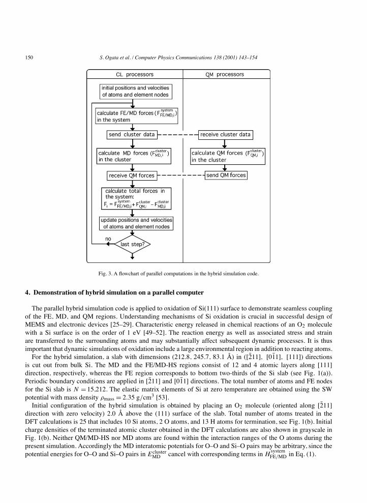
to the positions, velocities, and masses of the MD atoms and the FE nodes. Fig. 3 shows a flowchart of subsequentparallel computations:
(i) the classical forces { #F systemFE/MD} for all the MD atoms and the FE nodes are calculated in the CL processors;
(ii) atomic data for the QM and the QM/MD-HS atoms that are necessary to create an H-terminated cluster aretransferred to the QM processors;
(iii) the QM processors perform the DFT calculations to obtain QM forces { #F clusterQM } for the QM and the
QM/MD-HS atoms, while the CL processors calculate corresponding MD forces { #F clusterMD } using the
empirical interatomic potential;(iv) the QM forces are sent back to the CL processors; and,(v) the total forces { #F } = { #F system
FE/MD + #F clusterQM " #F cluster
MD } are calculated in the CL processors, which in turn areused for time-integration of the equations of motion using the velocity-Verlet algorithm [30].
In our additive hybridization scheme, the total energy of the system is a linear combination of FE/MD andQM energies. Consequently the CL and the QM subtasks are executed independently except for the exchange ofsmall messages containing species, coordinates, and QM forces for the cluster-atoms, as shown in the flowchartin Fig. 3. This modularity makes the present parallel implementation highly scalable, in contrast to multiplicativehybridization schemes that couple CL and QM tasks inseparably.
150 S. Ogata et al. / Computer Physics Communications 138 (2001) 143–154
Fig. 3. A flowchart of parallel computations in the hybrid simulation code.
4. Demonstration of hybrid simulation on a parallel computer
The parallel hybrid simulation code is applied to oxidation of Si(111) surface to demonstrate seamless couplingof the FE, MD, and QM regions. Understanding mechanisms of Si oxidation is crucial in successful design ofMEMS and electronic devices [25–29]. Characteristic energy released in chemical reactions of an O2 moleculewith a Si surface is on the order of 1 eV [49–52]. The reaction energy as well as associated stress and strainare transferred to the surrounding atoms and may substantially affect subsequent dynamic processes. It is thusimportant that dynamic simulations of oxidation include a large environmental region in addition to reacting atoms.For the hybrid simulation, a slab with dimensions (212.8, 245.7, 83.1 Å) in ([2̄11], [01̄1], [111]) directions
is cut out from bulk Si. The MD and the FE/MD-HS regions consist of 12 and 4 atomic layers along [111]direction, respectively, whereas the FE region corresponds to bottom two-thirds of the Si slab (see Fig. 1(a)).Periodic boundary conditions are applied in [2̄11] and [01̄1] directions. The total number of atoms and FE nodesfor the Si slab is N =15,212. The elastic matrix elements of Si at zero temperature are obtained using the SWpotential with mass density $mass = 2.35 g/cm3 [53].Initial configuration of the hybrid simulation is obtained by placing an O2 molecule (oriented along [2̄11]
direction with zero velocity) 2.0 Å above the (111) surface of the slab. Total number of atoms treated in theDFT calculations is 25 that includes 10 Si atoms, 2 O atoms, and 13 H atoms for termination, see Fig. 1(b). Initialcharge densities of the terminated atomic cluster obtained in the DFT calculations are also shown in grayscale inFig. 1(b). Neither QM/MD-HS nor MD atoms are found within the interaction ranges of the O atoms during thepresent simulation. Accordingly the MD interatomic potentials for O–O and Si–O pairs may be arbitrary, since thepotential energies for O–O and Si–O pairs in Ecluster
MD cancel with corresponding terms in HsystemFE/MD in Eq. (1).

S. Ogata et al. / Computer Physics Communications 138 (2001) 143–154 151
We have performed the hybrid simulation for 1000 fs using 9 processors (550 MHz Intel Pentium III) on a PCcluster interconnected with Fast Ethernet switches; 8 processors are assigned to the QM calculations. The MD timestep is 1.0 fs, and the finest mesh spacing of the real-space multigrids in the DFT calculations is 0.26 Å. Wall-clocktime per MD step is 15 min, 99% of which is spent for the electronic-structure calculations in the QM processors.A single self-consistent field cycle in the DFT takes 130 s in total including 20 s for data communication betweenthe QM processors.Fig. 4 shows snapshots of the atomic configuration at 150, 300, and 900 fs, in which [111] displacements of the
atoms and the FE nodes are color-coded. The O2 molecule dissociates and each O atom is captured by a Si–Si bondat the surface to form a Si–O–Si structure, which is associated with increase in the Si–Si distance. Resulting strainsin the QM region are transferred to the surrounding Si atoms in the MD region as shown in Fig. 4. Such strain
Fig. 4. Snapshots at 150, 300, and 900 fs in the hybrid simulation of oxidation of Si(111) surface. Colors represent [111]-displacements of theatoms and the FE nodes.

152 S. Ogata et al. / Computer Physics Communications 138 (2001) 143–154
waves reach the QM/MD-HS region at ) 300 fs, and propagate into the FE region at ) 900 fs with no reflection orrefraction observed at the QM/MD and MD/FE boundaries.To analyze the transfer of kinetic energy, we partition the total system into slices along the [111] direction and
calculate the kinetic energy of the atoms and the FE nodes in each slice. Fig. 5 shows time evolution of the kineticenergies in the slices; Z denotes the coordinate along the [111] axis and Zsurf corresponds to the position of thetop Si-layer. The four vertical lines around Zsurf " Z * 5 Å in Fig. 5 represent the positions of the QM/MD-HSatoms; the positions of the FE/MD-HS atoms are bounded by the two vertical lines at Zsurf"Z = 19.3 and 23.3 Å.In Fig. 5, the kinetic energy varies smoothly as a function of Z at all times, indicating seamless coupling of the FE,MD, and QM regions.The total energy, H , in Eq. (1) is a conserved quantity in the present hybrid scheme. Fig. 6 compares time
evolution ofH systemFE/MD/N andH/N . WhileH
systemFE/MD/N changes by 2+10"5 eV during 200–260 fs,H/N conserves
Fig. 5. Time evolution of kinetic energies in slices. Z is the position of a slice in [111]-axis; Zsurf, position of the surface atomic layer. Thefour vertical lines around Zsurf " Z * 5 Å represent the QM/MD-HS atoms; the FE/MD-HS atoms are bounded by the two vertical lines atZsurf " Z = 19.3 and 23.3 Å.
Fig. 6. Time evolution of HsystemFE/MD/N and H/N. N is the total number of atoms and FE nodes.

S. Ogata et al. / Computer Physics Communications 138 (2001) 143–154 153
well with fluctuations of 2+ 10"6 eV. Such an accurate conservation of the total energy is necessary to study heattransfer from the QM region to the MD and FE regions.
5. Concluding remarks
We have developed a hybrid FE/MD/QM simulation approach by coupling the FE method for a continuumwith the MD method for atomistic simulations and the real-space multigrid-based DFT for QM calculations.We have performed a hybrid simulation of oxidation of Si(111) surface to demonstrate seamless coupling of theFE, MD, and QM regions. The present hybridization approach embeds a single QM cluster in a MD simulation,but an extension to include multiple QM clusters described by various approximation methods such as the tight-bindingmethod is straightforward.Our parallel FE/MD/QM algorithm based on the modular, additive hybridizationscheme requires little data communication between the CL and the QM processors, and accordingly, it can beimplemented efficiently on a set of loosely-coupled computer clusters with low inter-cluster data transfer rates, byassigning the CL and the QM tasks to different computer clusters. Such hybrid simulations in “Grid”-computingenvironments [54,55] are in progress.
Acknowledgement
This work was supported by DOE, AFOSR, ARO, NSF, and NASA. The computations were performed ona 166-processor PC cluster at the Concurrent Computing Laboratory for Materials Simulations at Louisiana StateUniversity.We would like to thank Dr. Martina E. Bachlechner and Dr. George Z. Voyiadjis for fruitful discussions.
References
[1] J.H. Fendler (Ed.), Nanoparticles and Nanostructured Films, Wiley-VCH, New York, 1998.[2] R.J. Brook (Ed.), Concise Encyclopedia of Advanced Ceramic Materials, Pergamon, Cambridge, 1991.[3] Y.-M. Chiang, D. Birnie III, W.D. Kingery, Physical Ceramics, Wiley & Sons, New York, 1997.[4] P. Hoenberg, W. Kohn, Phys. Rev. 136 (1964) B864;
W. Kohn, L.J. Sham, Phys. Rev. 140 (1965) A1133.[5] W. Kohn, P. Vashishta, in: N.H. March, S. Lunqvist (Eds.), Inhomogeneous Electron Gas, Plenum, New York, 1983, p. 79.[6] E.S. Kryachko, E.V. Ludena (Eds.), Energy Density Funcional Theory of Many-Electron Systems, Kluwer, Boston, 1990.[7] See, e.g., M.C. Payne, M.P. Teter, D.C. Allan, T.A. Arias, J.D. Joannopoulos, Rev. Mod. Phys. 64 (1992) 1045.[8] F. Shimojo, T.J. Campbell, R.K. Kalia, A. Nakano, S. Ogata, P. Vashishta, K. Tsuruta, Future Generation Comp. Sys. 17 (2000) 279.[9] S. Ogata, F. Shimojo, A. Nakano, P. Vashishta, R.K. Kalia, Comp. Phys. Comm., in press.[10] A. Warshel, M. Levitt, J. Mol. Biol. 103 (1976) 227.[11] U.C. Singh, P.A. Kollman, J. Comp. Chem. 7 (1986) 718.[12] M.J. Field, P.A. Bash, M. Karplus, J. Comp. Chem. 11 (1990) 700.[13] C.S. Carmer, B. Weiner, M. Frenklach, J. Chem. Phys. 99 (1993) 1356.[14] M. Svensson, S. Hymbel, R.D.F. Froese, T. Matsubara, S. Sieber, K. Morokuma, J. Comp. Chem. 100 (1996) 19 357.[15] U. Eichler, C.M. Kölmel, J. Sauer, J. Comp. Chem. 18 (1996) 463.[16] S. Dapprich, I. Komáromi, K.S. Byun, K. Morokuma, M.J. Frisch, J. Mol. Struc. (Theochem) 1 (1999) 461–462.[17] Y. Kim, J.C. Corchado, J. Villá, J. Xing, D.G. Truhlar, J. Chem. Phys. 112 (2000) 2718.[18] J. Gao, M.A. Thompson (Eds.), Combined Quantum Mechanical and Molecular Mechanical Models, American Chem. Soc., Washington,
DC, 1998.[19] J.R. Chelikowsky, N. Troullier, Y. Saad, Phys. Rev. Lett. 72 (1994) 1240.[20] J.R. Chelikowsky, N. Troullier, K. Wu, Y. Saad, Phys. Rev. B 50 (1994) 11 355.[21] J.R. Chelikowsky, Y. Saad, S. Ögüt, I. Vasiliev, A. Stathopoulos, Phys. Stat. Sol. (b) 217 (2000) 173.[22] E.L. Briggs, D.J. Sullivan, J. Bernholc, Phys. Rev. B 54 (1996) 14 362.[23] J.-L. Fattebert, J. Bernholc, Phys. Rev. B 62 (2000) 1713.[24] J. Wang, T.L. Beck, J. Chem. Phys. 112 (2000) 9223.
154 S. Ogata et al. / Computer Physics Communications 138 (2001) 143–154
[25] A. Madhukar, J. Crystal Growth 163 (1996) 149.[26] S. Mantl, M. Dolle, St. Mesters, P.F.P. Fichtner, H.L. Bay, Appl. Phys. Lett. 67 (1995) 3459.[27] Q.T. Zhao, F. Klinkhammer, M. Dolle, L. Kappius, S. Mantl, Appl. Phys. Lett. 74 (1999) 454.[28] R.A. Kiehl, M. Yamaguchi, O. Ueda, N. Horiguchi, N. Yokoyama, Appl. Phys. Lett. 68 (1996) 478.[29] IEEE, Microelectromechanical Systems (MEMS), 1999 IEEE 12th International, IEEE, New York, 1999.[30] M.P. Allen, D. Tildesley, Computer Simulation of Liquids, Clarendon, Oxford, 1987.[31] A. Nakano, R.K. Kalia, P. Vashishta, Comput. Sci. Eng. 1 (5) (1999) 39.[32] A. Nakano, M.E. Bachlechner, P. Branicio, T.J. Campbell, I. Ebbsjö, R.K. Kalia, A. Madhukar, S. Ogata, A. Omeltchenko, J.P. Rino,
F. Shimojo, P. Walsh, P. Vashishta, IEEE Trans. Electron Devices 47 (2000) 1804.[33] R.D. Cook, D.S. Malkus, M.E. Plesha, Concepts and Applications of Finite Element Analysis, 3rd edn., Wiley, New York, 1989.[34] M. Mullins, M.A. Dokainish, Phil. Mag. A 46 (1982) 771.[35] S. Kohlhoff, P. Gumbsch, H.F. Fischmeister, Phil. Mag. A 64 (1991) 851.[36] F.E. Abraham, J.Q. Broughton, N. Bernstein, E. Kaxiras, Comp. Phys. 12 (1998) 538.[37] J.Q. Broughton, F.A. Abraham, N. Bernstein, E. Kaxiras, Phys. Rev. B 60 (1999) 2391.[38] E. Lidorikis, M.E. Bachlechner, R.K. Kalia, P. Vashishta, G.Z. Voyiadjis, in preparation.[39] J.A. Smirnova, L.V. Zhigilei, B.J. Garrison, Comput. Phys. Comm. 118 (1999) 11.[40] R.E. Rudd, J.Q. Broughton, Phys. Stat. Sol. (b) 217 (2000) 251.[41] F.H. Stillinger, T.A. Weber, Phys. Rev. B 31 (1985) 5262.[42] N. Troullier, J.L. Martins, Phys. Rev. B 43 (1991) 1993.[43] J.P. Perdew, K. Burke, M. Ernzerhof, Phys. Rev. Lett. 77 (1996) 3865.[44] G. Kresse, J. Furthmüller, Phys. Rev. B 54 (1996) 11 169.[45] See, e.g., W.H. Press, S.A. Teukolsky, W.T. Vetterling, B.P. Flannery, Numerical Recipes in Fortran, 2nd edn., Cambridge Univ. Press,
New York, 1992.[46] A. Brandt, Math. Comp. 31 (1977) 333.[47] V. Kumar, A. Grama, A. Gupta, G. Karypis, Introduction to Parallel Computing, Benjamin/Cummings, Redwood City, CA, 1994.[48] W. Gropp, E. Lusk, A. Skjellum, Using MPI, MIT Press, Cambridge, 1994.[49] Y. Miyamoto, A. Oshiyama, A. Ishitani, Solid State Comm. 74 (1990) 343.[50] T. Uchiyama, M. Tsukada, Phys. Rev. B 55 (1996) 9356.[51] K. Kato, T. Uda, K. Terakura, Phys. Rev. Lett. 80 (1998) 2000.[52] T. Hoshino, Y. Nishioka, Phys. Rev. B 61 (2000) 4705.[53] H. Balamane, T. Halicioglu, W.A. Tiller, Phys. Rev. B 46 (1992) 2250.[54] I. Foster, C. Kesselman, The Grid: Blueprint for a New Computing Infrastructure, Morgan Kaufmann, San Francisco, 1999.[55] I. Foster, J. Geisler, W.D. Gropp, N.T. Karonis, E. Lusk, G. Thiruvathukal, S. Tuecke, Parallel Comput. 24 (1998) 1735.