![Eckart[Harrison Mag]Ad](https://static.fdocuments.us/doc/165x107/556a8939d8b42ac9298b475f/eckartharrison-magad.jpg)
h w wy w [G - Eckart GmbH, Schlüchtern · in case of that, do we avoid a gap extrusion of the...
16
-
Upload
nguyenkhue -
Category
Documents
-
view
216 -
download
0
Transcript of h w wy w [G - Eckart GmbH, Schlüchtern · in case of that, do we avoid a gap extrusion of the...

2 Spot the advantages …
wear-resistant moving parts
- long service life of the rotary actuator through extended-period nitriding
- excellent sliding characteristics of the gears
fl exible mounting possibility - if front-fl ange- or foot mounting, with or without threads, we can fi t the E1 on all kind of practicable technical mounting possibilities
adjustable drive shaft datum - if you manufacture the hub, it is not necessary
to regard the exact position of the keyways.- the total angle can be re-adjusted at any time
minimal required space - we took great care, by the development,
to have small dimensions
ball bearing - in spite of the possibility is the radial- and axial
power through the application of ball bearings by low hydraulic pressure warranted
modern sealing technology
- extended service life of seals- increased safety, also with regard to the environment- suitable for most fl uids- all installation places have the smallest possible tolerances,
in case of that, do we avoid a gap extrusion of the seals.- no internal leakages through solid seals enabling the load to be held in any intermediate position
low hydraulic axial loadon drive shaft through small differential
- less load on the ball bearing, freeing it for more important tasks
- extending the service life of the rotary actuator

3
E1
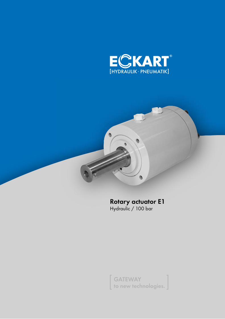
Rotary actuator E1
Contents
Features E1 2, 3
Function and features 4, 5
Modular down to the tiniest details 6, 7
End cushioning 8
Options 8, 9, 10
Technical data and information 11
Dimensions 12, 13
Important technical information 14
Size and hazard analysis 15
Applications 16
highly perfected end cushioning for absorption of kinetic energy
- negating the need for expensive proportional or servo controls with virtually identical
characteristics
large-area press-fit joint
- assuring positive power/torque transmission even at peak load conditions
…over time
- short delivery times through fl exible storage- individual solutions for your product- quality assurance according to DIN EN ISO 9001
from 10 bar economically applicable - through precise combined helical gears and low
friction seals, is the E1 already from 10 bar economically applicable
through shaft
- the axial force required for mounting the shaft on the hub can be exerted at the end of the shaft, preventing destruction of the ball bearing
- the mounting of components for the pivoting angle monitoring is possible without problems

4 Function and features
[ Operation ]
The rotary actuator E1 is used for rotating or turning useful loads.
As in a hydraulic cylinder the piston K (fi g.-2) is moved in a linear motion between the two mechanical end positions E1 and E2 by means of hydraulic power.
Through the multiple helical gears the linear motion is mecha-nically transformed into a turning motion and transferred to the drive shaft W.
The opposed direction of the helical gears G1 and G2 causes a simple stroke of the piston to produce a doubling of the angular movement.
The pairs of helical gears are not self-inhibiting. Positive lubrica-tion and nitriding of the surfaces of the helical gears ensures a long service life of the rotary actuator.
[ Operating pressure ]
The maximum operating pressure of the rotary actuator is 100 bar. Low friction seals allow the rotary actuator to operate from as low as 5 bar operating pressure and so can be economically set at approximately 10 bar.
For especially slow rotation stick-slip seals can be supplied as a special specifi cation.
[ Drive shaft datum ]
The drive shaft datum can be adjusted within the angular minute range. After loosening the screws Z (1/2 turn), any drive shaft or key position can be adjusted. Once the required adjustment has been made, tighten the screws Z again as instructed (see manual).The drive shaft datum is adjusted at the factory as shown in fi g.- 2, with the piston K resting against the stop E1 (also see pages 12 and 13).
[ Torque output ]
The stated torque fi gures are effective torques, with the pressure versus the torque curve being virtually linear. For multi-shift, heavy duty or high frequency applications a safety factor between 1.2 and 1.5 is recommended. Torque output is equal in both directions.
fi gure-2
F
ZS2
KE1
E2
G1
B1
G2
A
W S1
B
A1
5Rotary actuator E1
[ Shaft rotation ]
From view F, the drive shaft W will rotate anti-clockwise (arrow A) when pressure is applied to port A1. A different direction of rotation is available as a special feature.
[ Rotation ]
Standard rotations are 90�, 180�, 270� and 360�. Other rota-tions can be supplied on request by using the model with the next standard rotation up and limiting the stroke of the piston in accordance. Also available are special models with rotations in excess of 360�.
[ Backlash ]
In order to function, the set of helical gears require a certain backlash of approx. 20 angular minutes. On special request, the rotary actuator can also be supplied with a reduced backlash of as little as 5 angular minutes.
[ Fluids ]
We recommend mineral oil based hydraulic fl uids of the group HLP as per DIN 51524 / Part 2 and VDMA recommendation 24318. Fluids without emulsifying agents reduce the service life of the rotary actuator. For heavily fl ammable fl uids, please consult factory. The recommended viscosity range is 16 cSt to 68 cSt at 40� to 60� C.
[ Operating temperature ]
The operating temperature can range from -25� C to +70� C, providing suitable fl uids with the correct viscosity rating are used. Please contact us for any applications outside these limits.
[ Oil change ]
The oil change depends on the size of the system and should be carried out at regular intervals.
[ Filtration ]
The hydraulic fl uid used in the rotary actuator does not exceed the pollu tion classifi cation 19/15 in accordance with ISO 4406. Therefore, a fi lter setting of < 25 µm should be installed in the pressure line. With hermetically sealed containers a return fi lter should suffi ce. With open containers a pressure fi lter must be installed in the compressed air line. The maintenance inter-vals described above should be adhered to in line with manu-facturer specifi cations.
[ Leakage ]
The use of solid seals reduces leakage to the absolute minimum, therefore allowing the load to be held in any intermediate position.
[ End of stroke ]
The piston K (fi g. 2) can be moved under load against the end stops E1 and E2 and be loaded in this position.
The end stops are designed to withstand the force created by the maximum allowable operating pressure relating to the ma ximum premissable torque output.
If higher forces can be expected, we recommend installation of external stops or other methods of control such as end cushio-ning (see page 8 and 14) or control valves.
[ Installation, maintenance and running in ]
An operating instruction for the installation, maintenance and running in are provided with every delivery. Spare-part-list as well as dismantling and assembly instruction are available by request.
[ Non-standard options ]
In addition to the options listed in this catalogue, special features can also be supplied. A few ideas are listed on pages 6 and 7. Please contact our engineers for further information.
DO YOU
THOUGHT AT ALL?
Please use our
fax form
at page 15.

6 Modular down to the tiniest details …
[ Extras which give fl exibility ]
Successful companies gain competitive advantage, both for themselves and their customers, through innovative ideas and technologies. On the basis of E1, we have achieved special designs which are tailored precisely to your needs.
Please feel free to call us - our engineers and technicians will be pleased to help you.
a)
b)
c)
e)
f)
g)
h)
i)
j)
polygon shaft(also conical)
fl anged shaft
hollow shaft with square end
gear shaft
splined shaft
shaft with keys
shaft - smooth
hollow shaft with gear hub or with multiple-splined hub
hollow shaftwith keyways
with foot
fl ange - fl attened
fl ange with fi xing grooves
fl ange according to DIN ISO 5211
basic model
valve
valve plate

7Rotary actuator E1
with externally mounted end stop,to eleminate angle deviation
with additional radial bearing,for higher shaft load
stop valve plate
cushioning plate -all other types of thread possible
standard connection bores -all other types of thread possible
proximity switch -pressure resistant(to approx. 25°)
pressureabsorber
measuringconnection
bleed valve withhose liner
lockingscrew
fl ange with threaded boresas blind-end bore
fl ange with threaded boresas through bore
angle sensor, potentiometer with coupling andmounted housing
clamping ringwith proximityswitch
clamping ring with mechanical switch
locating pin
angular adjustment,e.g. from 90° to 180°
agraduated angular adjustment,e.g. from 0° to 90°
with second fl ange on base
with large fl angeat centre
with foot on base
with adjusting cylindere forintermediate angles of rotation
with second exit shaftalso possible with the types a) to j)(see page 4)
with outside square end for manual operation
cam

8 Options
A. Starting position
- piston K is in end position E2- port A1 is pressurised- port B1 (without connection plate drawed) is unpressurised
B. Reversing the directional control valve
- port B1 is pressurised- ball check valve R in port B1 opens- hydraulic fl uid fl ows freely into the cylinder space- piston K moves in the direction end position E1
(direction arrow piston K)- ball check valve R is closed in port A1- pressure medium fl ows off freely through the bores D
C. Cushioning process
- piston K now approaches the end position E1 and seals the bores D one after the other
- piston speed is progessively reduced- piston K now completely covers the bores D- pressure medium can now only escape through
the bore Q with the adjusting screw DS to the port A1- the cushioning effect can therefore be adjusted
again by the adjusting screw DS- the cushioning phase runs linear
[ Operation ]
The diagram shows one of the advantages of Eckart end cushioning over con-ventional cushioning with single-stage control.
fi gure-3
[ Z1- End cushioning ]
End cushioning is aimed at dissipating and/or decelerating the rotary movement before the fi nal end stop.
Eckart end cushioning is designed to meet the toughest require-ments in modern hydraulics. On the basis of continuous research and development as well as close co-operation with our cus-tomers, we can offer you state-of-the-art end cushioning.
● You do not need to include any expensive proportional or servo controls in order to dissipate kinetic energy, because Eckart end cushioning will perform this function almost identi-cally.
● Eckart end cushioning largely prevents pressure peaks, which often destroy rotary actuators with conventional single-stage cushioning or throttle regulation (see diagram in fi g. 3)
● The standard effective cushioning range in the end position is approx. 10� for all sizes. Other cushioning can be supplied on request.
● It is possible for the customer to adjust the cushioning effect individually by screwing in nozzles.
● End cushioning Z1 can also be delivered for each special angle of rotation (see too page 14).
pressure[bar]
300
200
100
pressure[bar]
300
200
100
single-stage end cushioning time [s] Eckart end cushioning time [s]
fi gure-4
DR
K
DSDM
Q
A1
B1D
connection plate
E1
R
Dimensions see page 12
E2

9Rotary actuator E1
[ Z2 - Externally adjustable end stop ]
The end angle can be re-adjusted at any time by ± 5�.In conjunction with the adjustable drive shaft datum, it is there-fore possible to adjust the initial and fi nal position of the total angle required.For adjustment, you only have to loose the counter nut KM. After this, you can reach the wished rotating angle through screwing in or out of the adjusting insert RE. A positioning is only possible, in the state of no pressure.
[ SM1 - Replaceable with SM1 ]
The Eckart E1 is the successor of the classic SM1 which was build for over 30 years and was used for over 100.000 times. We attach a lot of importance by the development concerning the reducement of the dimensions at the same time for the replacement to the SM1. With this option is the replaceability warranted.
fi gure5
[ Z4 - Longe-range adjustable end stop ]
The angle of rotation can be adjusted individually with this option, both over its total range of rotation and over a partialrange (e.g. total angle 270�, desired partial adjustment of 180� to 270�). To this end, the adjusting insert RE is simply screwed inwards or outwards to give the desired angle of rota-tion. The shaft goes all the way through, allowing control equip-ment to be fi tted. Adjustment is only possible in the unpressurised state. The long-range externally adjustable end stop Z4 is similar as shown on picture 5 and does only build, concerning the wished adjustable range longer (see too page 14).
[ FL - Flange design ]
The E1 can also be delivered with a fl ange instead of the tap-ped holes at the front surface. The fl ange is mounted on the front surface holes.
RE
KM
E2
Dimensions see page 12 + 13

10
14
3
143
2
Options
[ SZ - Locating pin ]
The locating pin SZ (fi g. 6) is intended for the fi tting of cams Z5 or other control equipment. It simply screws or is glued into the tapping provided at the back end of the shaft. It can be supplied at a later stage without reconstruction of the rotary actuator. The locating pin should not be used for torque transmission or for limiting the angle of rotation.
[ Z5 - Cam ]
The cam Z5 (fi g. 3) is clamped onto the locating pin SZ and is used to operate the control switches. If two cams are fi tted, the second one is reversed and fi tted upside down, while both cams remain individually adjustable.
[ ZW - Gear shaft DIN 5480 ]
The gear shaft profi le DIN 5480 is preferable to the standard key connection if high alternating and bending loads are expected. The profi le and assembly dimensions are given on page 13.
fi gure-6
[ Z6 - Control switch assembly ]
This option allows the respective end positions to be touchless and electronically confi rmed and the intermediate angles to be recalled. The locating pin SZ and the cam Z5 are included in this option. Also the mounting of a couple of control elements is possible, by this will only get the amount of the elements higher (for example 2 x Z6).
Technical data Z6 - inductive(fi g.-6):
control element: PNP normally open M12x1 nominal control interval: 2 mm operating voltage: 10 . . . 30 V DC current carrying capacity: 200 mA connection type: plug permissible temperature: -25�…+70�
system of protection: IP 67
Plugs are not delivered as standard! Concerning this we ask for your inquiry.
[ ZN - Gear hub DIN 5480 (hollow shaft) ]
Rotary actuators with a gear hub profi le as per DIN 5480 shorten the structural length of the total construction, or are used for if the customer’s counterpart can not be provided with a hub. The profi le and assembly dimensions are given on page 13.
Z6
Z5
SZ
Dimensions see page 12 + 13

11Technical data and information
[ Technical data ]
[ Important technical information ]
- Adherence to the data provided here is a precondition for trouble-free operation.- The regulations of the Technical Supervision, Social Insurance Against Occupational Hazards
and the respective environmental regulations etc. must be observed.- Plant driven by a rotary actuator must be laid out in such a manner that in case of technical or human failure
there is no danger of injury or death.- We reserve the right to alter or improve design specifi cations without prior notice.
[ Ordering code ]
E1 . 80 – 270° / … / ... / SO
options– omit for standard
non-standard options(consult factory) omit for standard
90°180°270°360°
rotation (standard) – other rotations available on reques
100 bar series
size (piston-Ø)
40 50 63 80 100 125
74 162 304 588 1275 2450
0,74 1,62 3,04 5,88 12,75 24,50
standard 90°/180°/270°/360° and any intermediate angle, even above 360°
recommended: mineral oil of group HLP/DIN 51524, page 2 and VDMA page 24318; others on request
5 to 10 bar
100 bar / higher on request
as required, provided that adequate air bleeding is provided
- 25°C to +70°C / higher or lower on request
0,17 0,38 0,7 1,43 2,98 5,86
0,13 0,18 0,24 0,26 0,43 0,55
4,0 6,5 10,0 13,7 23,8 39,0
4,6 7,5 11,8 16,4 29,0 48,0
5,2 8,5 13,6 19,1 34,2 57,0
5,8 9,5 15,4 21,8 39,4 66,0
0,589 1,864 3,434 7,358 8,829 11,772
1,472 2,453 4,905 8,829 11,772 17,658
0,245 0,392 0,589 0,758 1,117 1,472
Size (piston-Ø)
max. torque at 100 bar [Nm]
spec. torque [Nm/bar]
angle of rotation
medium
min. operating pressure required
max. allowable operating pressure
installation position
temperature range
absorption volume [cm3/1°]
max. admissible rotation time per 90° (without load) [s]
90°weight [kg] ca. 180°
By the female construction 270°is the weight about 7 % less. 360°
max. radial load FR [KN]
max. axial load FAE [KN]
max. axial load FAA [KN]
angle
Z1 - end cushioning FL - fl angeZ2 - Drehwinkeleinstellung HW - hollow shaftZ4 - long-range adjustable end stop SM1 - replaceable SM1Z5 - cam SZ - locating pinZ6 - control switch (ind.) ZN - gear hub DIN 5480 ZW - gear shaft DIN 5480

12
Dimensions
[ Standard model - size 40 - 125 ]
[ Model with hollow shaft - HW ]
[ Comments ]
1) Dimension varies for models including option Z4 = adjustment of angle of rotation. Please consult factory.2) max. length screwed out state3) Depth as per DIN 6885, page 3 Order code on page 11
Rotary actuator E1 øA øA1 øB øB1 øB2 C øC1 øD øD1 øD2 øE3 øE4 øF øF1 G G1 G2 G3 H I J J1 K1) K1 L1)
h7 h7 /Gew.depth k6 H7 90° 180° 270° 360° 90° 180° 270° 360° 90° 180° 270° 360°
45 40 65 90 73 M6/13 6,5 78 103 85 12 52 18 — 50 — 50 — 55,5 3 10 11 119,5 145,8 172,6 199,4 133 159,8 186,6 213,4 6 18,9 32,3 45,7
55 50 80 105 86 M6/13 6,5 93 118 98 12 62 25 — 60 — 60 35 67 4 11,5 11 135,6 169,1 205,1 241,1 147,6 183,6 219,6 255,6 8 23,5 41,5 59,5
65 60 93 125 102 M8/18 9 110 140 116 20 80 30 24 80 65 80 40 88 5 13,5 14 149 193 237 281 164,9 208,9 252,9 296,9 8,3 30,3 52,3 74,3
80 70 105 143 130 M10/20 11 123 163 150 20 92 35 30 80 85 80 45 89 6 14 18 172,8 226,8 280,8 334,8 190,2 244,2 298,2 352,2 17,5 44,5 71,5 98,5
105 80 130 168 143 M10/20 11 148 188 160 28 116 45 45 110 102 110 55 120 6 17 20 205,5 277,1 348,7 420,3 226,5 298,1 369,7 441,3 25,4 61,2 97 132,8
125 100 155 200 182 M12/24 13 177 225 205 32 140 60 55 140 120 140 60 152 7 19,5 21 237,4 327,4 417,4 507,4 260,2 350,2 440,2 530,2 34,6 79,6 124,6 169,6
Size(piston-Ø)
40506380
100125
[ Locating pin - SZ ]
[ Model with end cushioning - Z1 ]
Kair bleeds
L
W
VØ B
V
90° + 1°works
adjustment
Ø D
W1
V1 V1
90° + 1°works
adjustment
Q1
SZ
30
10
F1
G1
N1M1
Q QOO
SE3 E4
M820 deep
NMH
Ø A
Ø F
C
G
UT
I O O
E1
DO YOU
THOUGHT AT ALL?
Please use our
fax form
at page 15.

13
Rotary actuator E1
[ Model with gear shaft profi le DIN 5480 - ZW ]
[ Model with gear hub profi le DIN 5480 - ZN ]
90° + 1°
Rotary actuator E1 ZW ZN Z6 L12) M M1 N N1 O Q Q1 S T T1 U V V13) W W1 DIN DIN b
90° 180° 270° 360° 90° 180° 270° 360° 90° 180° 270° 360° port size 5480 5480
19,5 32,9 46,3 59,7 35 38,3 75 88,4 101,8 115,2 71,8 85,2 98,6 112 G1/4” 37 40 60 1,5 35 45 11,5 — 6 — — 96
18 36 54 72 43 43,1 87 105 123 141 83,1 101,1 119,1 137,1 G1/4” 37 40 68 3 40 50 15,5 — 8 — 96
24,2 46,2 68,2 90,2 44 46,4 92 114 136 158 90,6 112,6 134,6 156,6 G1/4” 37 40 76,5 4 55 70 18 14 8 8 96
34,9 61,9 88,9 115,9 48 51 109 136 163 190 105 132 159 186 G3/8” 37 40 83,5 4 55 70 20,5 18,3 10 8 96
46,4 82,2 118 153,8 60 61 132 167,8 203,6 239,4 127,2 163 198,8 234,6 G3/8” 37 40 96,5 4 80 100 26 26,3 14 14 96
57,4 102,4 147,4 192,4 65 67 150 195 240 285 143,5 188,5 233,5 278,5 G3/8” 37 40 111 5 105 125 34 31,8 18 16 96
Size(piston-Ø)
40506380
100125
DIN6885
DIN6885
DIN6885
DIN6885
DIN6885
W18x1,25x13x8f
W25x1,25x18x8fW30x2x14x8fW35x2x16x8fW45x2x21x8fW60x3x18x8f
N22x1,25x16x9H
N25x1,25x18x9HN35x2x16x9HN48x3x14x9HN60x3x18x9H
[ Model with fl ange - FL ] [ Externally djustable end stop - Z2 ]
[ Replaceable - SM1 ] [ Cam - Z5 ]
[ Control switch - Z6 ]
90° + 1°
Ø D
1Ø
A
I J1
H
Ø D
2Ø
A1
J
V VØ B1
W
3 x 90°
45°
C1
E4
K1
L1
V VØ B2
W
3 x 90°
45°
C1
201010
20
G2T1
G3 LED
96
H
- We reserve the right to alter or improve design specifi cations without prior notice. - Non-standard options on request
14 Important technical information
Because of its torque, angle of rotation, pressure range, po-sitioning accuracy, stability of position, type of attachment and dimensions, the Eckart E1 rotary actuator can be used in a wide range of applications.
The selection and the size depends above all on the de-mands and the operating conditions under which the rotary actuator is operating. For the planning of special items, it is also important for us to be aware of all technical details.
In order to provide this we have prepared a catalogue of questions on page 15 which you can fax us if any lack of clarity emerge. Our staff will be glad to work out and submit a proposal to you.
We accept no guarantee claims for disturbances in functio-ning or complaints which are attributable to lack of informa-tion by the customer.
[ When planning the rotary actuator, we recommend the following ]
● The mechanical stops within the rotary actuator are designed to withstand the force created by the maximum allowable operating pressure relating to the maximum permissible torque output. If they are used to stop the load, the forces acting on them, including forces of inertia, must not exceed the force created by the maximum operating pressure.
If higher forces can be expected, we recommend installation of external stops or other methods of control such as end cushioning, as described below, or control valves.
● On hermetic locking of the rotary actuator (e.g. hydraulically controlled double release valves) and the impact of resetting force on the axle a holding pressure is generated. If the holding pressure reaches the level of the operating pressure there is a torque increase on the axle of 38 %. If resetting forces are expected this should be refl ected in selecting the size of the rotary actuator. This also has to be taken into con-sideration in those cases of operation in which the optional end cushioning Z1 is used.
● In order to guarantee a fresh supply of pressure fl uid or me-dium, the pressure connection lines should be kept as short as possible, and/or the directional control valve should be mounted directly onto the rotary actuator. If this is not possible, we recommend a hydraulically controlled double release valve with additional tank line.
● On hermetic locking of the rotary actuator (e.g. hydraulically controlled blocking valves) and the impact of heat from external sources it should be considered that the hydraulic pressure in the rotary actuator increases by about 6 -8 bar per 1�C increase of the temperature. In case of substantial temperature increase the rotary actuator could be destroyed. If operating conditions with substantial temperature increases are expected, appropriate protective measures (e.g. safety valves, cycles of operation) should be provided.
● During installation, care should be taken that the drive shaft or hub is perfectly aligned with the counterpart, since otherwise the maximum permissible radial and axial forces can easily be exceeded.
● In case of externally adjustable end stop Z2 on actuators with the end cushioning option Z1, the cushioning effect on the bottom side should also be changed.
● By the combination of both options longe-range externally adjustable end stop Z4 and end cushioning Z1 is the building of the bottom end cushioning not possible.
● Ensure that air bleeding S1/S2 is accessible (important in the case of end cushioning Z1)
● The rotary actuator needs to be dismantled when changing replacement parts. It is therefore necessary to allow enough clearance for this to be carried out easily.
● In case of rotary actuators with the end cushioning option Z1, the fl owing back of the pressure medium is progressively throttled down which causes the hydraulic pressure to rise on the cushioned side of the piston. In this context it must be ensured that the anticipated cushioning pressure does not exceed the operating pressure maximally admissible.
As not all factors can be exactly pre-determined, not all requi-rement profi les can be implemented in confi gurations which use the end cushioning Z1. For this reason the details of the execution for the end cushioning Z1 must be established under all circumstances during the commissioning of the initial delivery of rotary actuators (we will be glad to assist you con-cerning this).

15
company name
department name/ref.
street
country/postcode/place
phone fax
date project no.
ECKART GmbHconstruction/sales departmentAm Knöschen 236381 Schlüchtern
Tel. +49 (0)6661 9628-0Fax +49 (0)6661 9628-50
E-Mail [email protected]
We calculate for you!
options
A B C D E F G
1
2
fi tting position of rotary actuators
3 angle of rotation, max. �
4 angle of rotation, in operate �
5 rotation time, total tg sec.
6 cushioning time td sec.
7 cycle frequency T sec.
8 duration of operation per day h
9 torque output Md Nm
10 mass moment of inertia I kgm2
11 lever r mm
12 centre of mass R mm
13 mass m kg
14 reset power, holding power Mr Nm
15 radial load FR N
16 axial load FAA N
17 axial load FAE N
18 required working pressure PA bar
19 maximum operating pressure PB bar
20 pressure peaks PS bar
21 medium
22 temperature of medium � C
23 temperature of environment � C
24 volume fl ow Q l/min.
25 stops ■■ internal ■■ external
26 Z4 range of adjustment
sketch/special features/fi eld of application/circuit diagram
FR
FAA
FAE
Size and hazard analysis
Z1 Z2 Z4 Z5 Z6 FL HW SM1 SZ ZN ZW
FAX to +49 (0)6661 9628-50

16 Applications
distributed by:
ECKART GmbHAm Knöschen 236381 SchlüchternGermany
Tel. +49 (0)6661 9628-0Fax +49 (0)6661 9628-50E-Mail [email protected]
[ www.eckart-gmbh.de ]
© E
CK
ART
Gm
bH 2
007
Prod
uctio
n 10
/200
7 . G
ünth
er W
erbe
serv
ice
linear actuation bending machines
gate valve control conveyor belts work piece positioning / changing
tool change
rotational devicesopening / closingtipping devices


