H P 4 crl 0 w M 4 H Cl H - University of Calgarypubs.aina.ucalgary.ca/gran/55095.pdf · push-outs...
38
H z Cl H z 4 M w n m i 0 crl crl 4 P H m H Cl -I. 1- ..
Transcript of H P 4 crl 0 w M 4 H Cl H - University of Calgarypubs.aina.ucalgary.ca/gran/55095.pdf · push-outs...

H
z
Cl
H
z
4
M
w
n
m
i
0
crl
crl
4
P
H
m
H
Cl
-I
.
1-
.
.

* D E P A R T M E N T O F I N D I A N A F F A I R S AND NORTHERN DEVELOPMENT
NORTHERN OPERATIONS BRANCH
LAND U S E P E R M I T
PERMIT - C l a s s A NUMBER N78E778
SUBJECT TO T H E T E R R I T O R I A L LAND USE REGULATIONS AND THE TERMS AND C O N D I T I O N S I N T H I S p e r m i t AUTHORITY I S HEREBY GRANTED TO:
TO PROCEED WITH THE LAND USE OPERATION DESCRIBED in THE APPLICATION OF:
FEBRUARY 1, 1978 DATE
F ,F KIMBALL S I G N E D BY
MILE 2 1 - 6 L 5 , LIARD HIGHWAY - TYPE OF LAND USE OPERATION
L I A R D highway LOCATION
T H I S P E R M I T - MAY BE ASSIGNEDf EXTENDED, DISCONTINUED, SUSPENDED OR CANCELLED PURSUANT TO THE TERRITORIAL LAND USE REGULATIONS.
"
DATED AT YELLOWKNIFE , N . W .T . /
T H I S DAY OF march 1978
MARCH 6, 1973 - c o m m e n c e m e n t DATE
March 6, 1980 EXPIRY DATE
NOTE: T H E G R A N T I N G O F - T H I S P E R M I T D O E S NOT R E L I E V E THE P E R M I T T E E FROM OBSERVING AND COMPLYING WITH ANY O T H E R A P P L I C A B L E A C T S , REGULATIONS, ORDINANCES , BY-LAWS OR ORDERS.

- 1 - . - ". a
o p e r a t i n g CONDITIONS - PART I
T h e Operator d e p a r t m e n t OF public works - C a n a d a s h a l l conduct t h e right of way CLEARING MILE 21-66.5, liard Highway
Land use Opera t ion au tho r i zed by t h i s Land Use p e r m i t in accordance with t h e following operating condi t ions : ' -
g e n e r a l c o n d i t i o n s
1. THE o p e r a t o r SHALL adhere TO ALL APPLICABLE c o n d i t i o n s STATED in PART I ( G e n e r a l ) OF THE territorial land USE r e g u l a t i o n s
2. the OPERATOR'S FIELD supervisor shall c o n t a c t THE fort simpson DISTRICT OFFICE OF THE northwest lands and FOREST SERVICE PHONE number 695-2231 FORTY e i g h t HOURS PRIOR TO THE commencement OF THIS LAND USE o p e r a t i o n
4 . PRIOR APPROVAL shall be o b t a i n e d t h r o u g h THE land USE INSPECTOR for PROPOSED c h a n g e s in THE a p p r o v e d plan OF operations camp l o c a t i o n s and OTHER a s s o c i a t e d F A C I L I T I E S .
6 . installation OF EROSION CONTROLS and CLEANUP OF waste WILL be c o n t i n u o u s and k e e p PACE with PROJECT ACTIVITY.
"
7 . n o t w i t h s t a n d i n g t h e TERMINATION OF t h e p e r m i t THE o b l i g a t i o n OF TEE operator with RESPECT TO cleanup and r e s t o r a t i o n DOES NOT CEASE until
SECTION, diand y e l l o w k n i f e N.W. T. he IS in POSSESSION OF A LETTER OF clearance from THE head land use
\

I
8.
9.
10.
11.
12.
"
PRIOR TO THE i n s t a l l a t i o n OF fuel s t o r a g e F A C I L I T I E S e x c e e d i n g 5,000. GALLONS THE o p e r a t o r w i l l REQUIRE w r i t t e n APPROVAL from the head l a n d USE section diand y e l l o w k n i f e N.W.T.
FOR FUEL storage FACILITIES OF 5,000 GALLONS OR LESS THE OPERATOR SHALL LOCATE and PLACE FUEL STORAGE c o n t a i n e r s SO t h a t ANY s p i l l e d OR LEAKED FUEL w i l l BE TOTALLY c o n t a i n e d
FUEL OUTLETS e x c e p t i n g t h e outlet currently I N use SHALL BE SEALED TO p r e v e n t l e a k a g e
THE land USE INSPECTOR WILL BE i n f o r m e d OF THE LOCATION OF ALL fuel CACHES.
ALL stationary fuel storage FACILITIES SHALL be CLEARLY marked w i t h flags OR POSTS SO they ARE p l a i n l y V I S I B L E , r e g a r d l e s s OF snow COVES, w e a t h e r OR DAYLIGHT c o n d i t i o n s
:
WILDLIFE
15. (A) a l l firearms SHALL BE u n d e r THE c o n t r o l OF s u p e r v i s o r s and be USED only FOR PROTECTION.
(B) THE p r e s e n c e OF A wild animal t h a t may c r e a t e a hazard I S TO BE REPORTED i m m e d i a t e l y TO THE nearest game management o f f i c e r OR R. C m P d e t a c h e m e n t
(C) THE feeding OF w i l d l i f e I S p r o h i b i t e d
16. FOOD and c a m p k i t c h e n WASTE w i l l BE h a n d l e d I N A m a n n e r TO AVOID a t t r a c t i n g w i l d l i f e
17. h u n t i n g I S p r o h i b i t e d FOR PERSONS employed BY t h e o p e r a t o r OR c o n t r a c t o r AND resident I N A p e r m i t t e e OR CONTRACTOR o p e r a t e d c a m p ( I .E. camps w i l l NOT BE USED AS A BASE FOR h u n t i n g

21.
22.
- 3 -
w i n t e r ACCESS ROADS SHALL BE OF p a c k e d snow c o n s t r u c t i o n
I N ORDER TO MINIMIZE SURFACE d i s t u r b a n c e BULLDOZER blades when USED OUTSIDE THE AREA OF c o n s t r u c t i o n ACTIVITY SHALL BE ELEVATED A minimum OF SIX inches ABOVE THE ground BY mushroom-type SHOES OR A s i m i l a r
the o p e r a t o r s h a l l PRESCCUT PROPOSED ROUTES and LINES and SHALL INDICATE WITH ground markers THE MOST f a v o r a b l e l o c a t i o n s FOR CROSSING streams OR AVOIDING TERRAIN OBSTACLES PRIOR TO movement OF CRAWLER t r a c t o r s OR OTHER HEAVY VEHICLES.
' c
SHOULD EXCESSIVE TERRAIN DAMGE RESULT from v e h i c l e s their USE WILL BE LIMITED OR STOPPED by THE LAND USE INSPECTOR.
a r c h a e o l o g i c a l
2 3 , (A) ARCHGOLOGICAL f i n d s m u s t BE made known TO the land USE INSPECTOR.

row clearance and construction - PART II
2 4 . IN ORDER TO m i n i m i z e SURFACE d i s t u r b a n c e OR SOIL SUBSIDENCE t h e operator shall prepare THE GROUND s u r f a c e beneath ALL FACILITIES AND structures ASSOCLATED w i t h t h i s l a n d USE OPERATION.
25. P )RTABLE ramps WILL BE USED FOR barge l o a d i n g and u n l o a d i n g push-outs w i l l SOT BE USED u n l e s s authorized BY t h e l a n d USE inspector

- 5 -
35. ON A R E A S ADJACENT TO BORROW P I T S AND DESIGNATED AS SPOIL AREAS, TITlBER AND b r u s h m a t e r i a l s w i l l DE w a l k e d down PRIOR TO THE p l a c e m e n t OF SPOIL MATERIALS.
36. leaners AND DEBRIS s h a l l NOT BE LEFT I N STANDING TIMBER.
GRUBBING (OR s t r i p p i n g
38. g r u b b i n g SHALL BE c o n f i n e d TO minimum AREAS FOR PURPOSES OF CUTS, d i t c h i n g a n d BORROW PITS .
39. movement OF g r u b b i n g EQUIPMENT SHALL BE CONFINED TO AREAS TO be GRUBBED AND r i g h t - o f - w a y
40 . DISPOSAL OF g r u b b e d material w i l l BE BY b u r n i n g OR b u r i a l
ACCESS roads
41. ACCESS ROUTES r e q u i r e PRIOR a p p r o v a l BY THE land USE INSPECTOR.
42.- ACCESS TO borrow P I T S shall RE l i m i t e d TO:
(B) two ROUTES OF A MINT"1 WIDTH n e c e s s a r y FOR one-way PASSAGE OF VEHICLES.
43. DOGLEG a p p r o a c h e s ARE r e q u i r e d ON ALL b o r r o w P I T ACCESS ROADS.
4 4 . TOTAL DISPOSAL OF TIMBER ON ACCESS ROADS SHALL BE CARRIED OUT TO the l i m i t OF VISISILITY from the f i n i s h e d roadway
borrow P I T S and w a s t e P I L E S
45 .
4 6 .
47.
I N t i m b e r e d A R E A S A RESIDUAL t i m b e r STAND OF 300 FEET s h a l l be m a i n t a i n e d BETTEEN THE highway and BORROW or w a s t e areas UNLESS OTHERWISE AUTHORIZED BY THE land USE INSPECTOR.

- 6 -
4 8 . b a c k s l o p e s I N BORROW AREAS s h a l l b e m a i n t a i n e d AT A SLOPE OF TWO horizontal TO one VERTICAL FOR common EXCAVATION, OR o t h e r w i s e TO THE SATISFACTION OF the land US& i n s p e c t o r
50. LEVELLING AND shaping OF w a s t e P I L E S WILL be PROGRESSIVE WITH OPERATIONS.
drainage AND s t r eams CROSS i n g s ". - 51.
52.
53.
5 4 .
55.
56.
THE OPERATOR SHALL make t e m p o r a r y CROSSINGS OF s t r e a m s I N SUCH A MANNER AS TO A V O I D e x c a v a t i n g OR OTHERWISE u n d u l y d i s t u r b i n g APPROACHES, shores BANKS and s t r e a m b e d s and n o t w i t h s t a n d i n g THE FOREGOING, S O e x c a v a t i o n s SHALL BE made w i t h o u t t h e PRIOR APPROVAL OF THE LAND USE inspector no debris w i l l b e DEPOSITED IN any s t r e a m d u r i n g the o p e r a t i o n s
THE p l a c e m e n t OF c u l v e r t s WILL BE p r o g r e s s i v e w i t h g r a d e c o n s t r u c t i o n I N ORDER TO prevent o b s t r u c t i o n 50 normal drainage
drainage WILL BE PROVIDED FOR WHEN e s t a b l i s h i n g ACCESS ROADS.
EXCAVATED m a t e r i a l not s u i t a b l e FOR PROJECT USE must BE DISPOSED OF IN A l o c a t i o n and manner SATISFACTORY TO THE land USE i n s p e c t o r
any o b s t r u c t i o n TO n a t u a r a l drainage o c c u r i n g during THE l a n d USE o p e r a t i o n shall BE removed and c o n d i t i o n s RESTORED TO THE ORIGINAL STATE AS QUICKLY AS POSSISLE.

DEPARTMENT OF PUBLIC WORKS
WESTERN REGION
REPORT ON
GEOTECHNICAL INVESTIGATION
KILOMETER 207 TO KILOMETER 254
FT. LIARD HIGHWAY
Submitted by R.D. Cook, P.Eng. Geotechnical Engineer August 10, 1978

TABLE OF CONTENTS
Item Page
I Introduction 1
1.1 General 1 1.2 Scope of Field Programme 1 1,. 3 Field Procedures 2 1.4 Numbering and Classification Systems 5 1.5 Permafrost Ice Description 6
II Summary of Results 7
2.1 General Geology 7 2.2 Kilometer by Kilometer Comments. 9 2.3 Ft. Liard Access Road 19 2.4 Granular borrow source at Ft. Liard ' 20
Appendix A - Borehole Logs

I INTRODUCTION
1.1 General
This report presents the results of a centerline soil
survey and assessment of potential borrow sources along
the Ft. Liard highway route between the Muskeg River
(km 207) and the British Columbia border (km 254.5).
The objectives of this geotechnical programme were to
identify and classify the subgrade soils along the
route; to evaluate their suitability for conventional
"cut and fill embankment construction; to locate and
evaluate sources of embankment borrow as required; and
to evaluate all potential sources of granular surfacing
materials within a reasonable haul distance of the
right-of -way.
-
F i e l d work on thls section of the highway was carried
out during the course of a field investigation over the
entire non-completed length of the Ft. Liard Highway in
the N . W . T . , i.e. from km 35 to km 254.5. This overall
programme, as described below commenced in mid January, 1978 and was completed near the end of March.
1.2 Scope of Field Programme
Field operations were carried out from a mobile camp
and commenced near Ft. Simpson and proceeded toward the
-
b.c. border drilling equipment was supplied by P.W.C.
and camp and caterpillar support were provided on a

- 2 -
contract basis. The field crew averaged 15 throughout
the work, consisting of eight (8) to nine (9) P.W.C.
staff, and six (6) to seven (7) contractor employees.
During the course of the field programme approximately
1500 holes were drilled, logged and sampled. A total
of 129 potential borrow areas were investigated.
Approximately 8000 samples were taken and moisture
contents and visual classifications were obtained on
all samples in the Departmental Laboratory in Edmonton.
Selected representative samples, primarily from major
highway cut sections and from borrow sources , were subjected to more extensive classification testing.
1.3 Field Procedures
Field work was under the direction of a geotechnical
engineer with the assistance of a senior technician,
responsible for field location and clearing of borrow
sites, and flagging test holes. Technicians assigned
to each drill crew were responsible for logging boreholes,
field identification of soil, sampling, packaging and
labelling of all samples.
Prior to the commencement of field work, and throughout
the course of the work, aerial photograph analysis was
employed to evaluate the terrain and select potential
borrow sites. Centerline drill hole locations were
determined primarily from a tentative gradeline along

- 3 -
the centerline profile,with some modifications made on
the basis of terrain observations during flagging. The
extent of borrow search along any portion of the route
was modified daily on the basis of suitability of the
right-of-way subsoils for cut and borrow. Drill hole
locations were marked on centerline profiles, or, in the
case of borrow search, on air photos or air photo
mosaics.
The following criteria, based on both construction and
environmental considerations, generally were observed
in hole layout for borrow:
1) Seismic lines and trails were used for access
whenever possible;
21 An attempt was made to locate access lines so
they could be used for future haul roads;
3 ) In order to screen future borrow activity from
the highway, all access lines were 'dog-legged'
at a distance of approximately 75 m (250 feet)
off centerline;
4 ) Holes were not located within 9 0 m (300 feet) of
centerline, nor within 90 m (300 feet) of lakes
or streams, as environmental restrictions
dictated against obtaining borrow within these
limits;
5) Wherever possible a portion of a potential borrow
source was selected for investigation in such a

- 4 -
manner that the pit, if developed, would not be
visible from the highway and would have good
drainage;
6) Access lines were cleared with a minimum cutting
of trees and disturbance to the organic cover,
and all lines were 'cleaned up' with all
'leaners' knocked down and brush cover piled on
one side of the lines.
A track mounted Mobile €3-50 auger rig using 15 cm (six
inch) solid stem flight augers was used for the majority
of the work. This rig was double shifted until the
last three ( 3 ) weeks of the programme when a truck
mounted auger rig was brought in via Ft. Nelson and
Ft. Liard as a supplement.
Centerline test holes were generally drilled to a depth
of 3 to 3 . 3 m (10 to 11 feet) or, in major cut
sections, below the tentative gradeline elevation.
Disturbed 'gra5' samples were obtained off the augers
at depths of 0.5 rn (1 .5 ' ) , 0 .9 m ( 3 ' ) , 1.5 m ( 5 ' 1 , 2.4 m
(8'), 3 . 3 m (ll'), 4.6 m (15'), 6 m ( 2 0 ' ) , 7.6 m ( 2 5 ' ) ,
etc.
Borrow area test holes were usually advanced to depths
of 6 m to 9 m (20 to 30 feet) with identical sampling
methods and depths.
All samples were returned to the Departmental laboratory

- 5 -
in Edmonton, and were visually identified, assessed as
to relative moisture content, and tested for natural
moisture content. Additional testing was carried out
on selected samples from borrow pits and major cut sec-
tions - usually both grain size analysis and Atterberg Limits were performed. Final borehole logs were then
prepared with both field and laboratory data included,
for evaluation and reporting.
- 1.4 Numbering and Classification Systems
A. - Borehole Numbering
Boreholes on centerline were prefixed with the
kilometre in which it was located, identified by
the letter C to indicate centerline, and then
progressively numbered within each kilometre. Thus
hole No. 102-C-4 is the fourth hole drilled on
centerline between km 102 and km 103.
Borrow areas were numbered consecutively from km 35
south and holes for borrow investigations were
prefixed by the pit number. Subsequently, the
kilometre in which the borrow area is located was
added to the number, i.e. #242-128B-3 indicates the
3rd hole drilled in borrow area 128 which is
located between kilometre 242 and 243.
- B. Soils Classification
Soils were classified according to the Unified
Classification System which is outlined at the rear

- 6 -
Atterberg Limits
plastic limit
liquid limit
of this text.
Soil samples were also categorized in the laboratory
using a series of terms to indicate the relative
moisture content of the soil. The terms and their
approximate relationship to the Atterberg Limits
are summarized below:
Relative Moisture Content
I dry'
' humid ' ' damp ' 'moist'
'wet'
' saturated' 'free water'
The above information is included on the borehole
log sheets for all samples.
- 1.5 Permafrost Ice Description
Very little permafrost is present along the highway
location; that which was encountered occurs as random
pockets often overlain by muskeg. The ice classification
system used was the National Research Council system
which follows this text. In addition to the N.R.C.
classification, the logging technicians also employed a
series of relative terms to indicate the amount of visual
ground ice. These terms and their approximate relation-

' low'
'moderate'
' high '
- 7 -
s h i p t o ground ice are out l ined below:
R e l a t i v e T e r m Vi sua l Ground Ice
' n i l ' - f r o z e n , b u t l i t t l e or no ice i n
any form - usua l ly con f ined t o d r y
s u r f a c e g r a v e l s o r bedrock.
- ice c o a t i n g s , ice c r y s t a l s a n d ,
poss ib ly , occas iona l ve ry small
l e n s e s .
- numerous small ice l e n s e s .
- cont inuous small ice l e n s e s w i t h
a s i g n i f i c a n t amount of l a r g e
( 1 . 3 c m +) (1/2 +) ice l e n s e s .
'very h igh ' - con t inuous l a rge ice l e n s e s .
' ice ' - ice wi th some s o i l , o r clear ice.
II SUMMARY OF RESULTS
Muskeg River t o B.C. Boundary
T e s t d r i l l i n g a l o n g t h i s s e c t i o n of t h e Highway c o n s i s t e d
of 2 8 0 c e n t e r l i n e h o l e s p l u s 115 h o l e s i n 30 p o t e n t i a l
borrow areas. All h o l e l o c a t i o n s are shown on t h e
1:10,000 a i r p h o t o mosaics inc luded w i th t he des ign
package. Borehole l o g s are included in Appendix A.
- 2 . 1 General Geology
The highway route covered by t h i s r e p o r t b e g i n s a t t h e

- 8 -
crossing of the Muskeg River (km 207.7), parallels the
Liard River valley to the Ft. Liard access road (km 217),
then turns S.E. and parallels the Petitot River to the
B.C. boundary (km 254 .5 ) .
The dominant surficial feature within this section is
the Maxhamish Escarpment - a long ridge of exposed sedimentary bedrock projecting some 1 2 5 to 150 m above
the surrounding terrain. The route intersects and
crosses the lower end of this ridge at about km 250.
The Maxhamish escarpment is an anticline exposing
limestones, quartzose sandstone, and sandy shale.
Between this ridge and the Liard River to the west the
underlying bedrock is sedimentary sandstones, siltstones,
and shales. Topographically this area is generally flat
with the Petitot River flowing in a narrow valley cut
down some 150 m below the relatively flat upland.
The upland is covered with glacial till, much of it
highly sculptured by advancing ice into prominent
flutings and till drumlins. These till ridges are
oriented in a general North-South direction hence the
route from Ft. Liard to the border crosses these features
at right angles. Depressions between the till ridges
tend to carry shallow or surface muskeg with occasional
deep muskeg (infilled lakes) and occasional shallow
ponds.

- 9 -
There is a conspicuous lack of granular ice deposits
on the till upland. All sorted granular deposits
within this section are fluvial deposits along and at
the mouth of the Petitot River.
The following describes this portion of the rou
the test boring results in detail.
ute and
2.2 Kilometre by Kilometre Comments
Kilometre 207 to 208.7
This is the crossing of the Muskeg River and the present
valley floor of the Muskeg River.valley.
-
The present Muskeg River valley is probably located in a
much larger old, pre-glacial channel that was eroded
through glacial till and bedrock. During the last
deglaciation period this valley was infilled with
alluvial silts, sands and some gravels, much of which
have been scoured and eroded out by the river to the
present floodplain. There remain remnants of these
former deposits on both sides of the valley extending
well above the present valley floor.
Deposits below the present floodplain along the right-
of-way consist of surficial silts and sands with a
shallow stratum C2 - 3 m) of sandy gravel
at depth. At the crossing and on the North side of the
river the alluvial deposits are at least 25 - 30 m deep. On the south side near the valley wall the alluvial
- 10 -
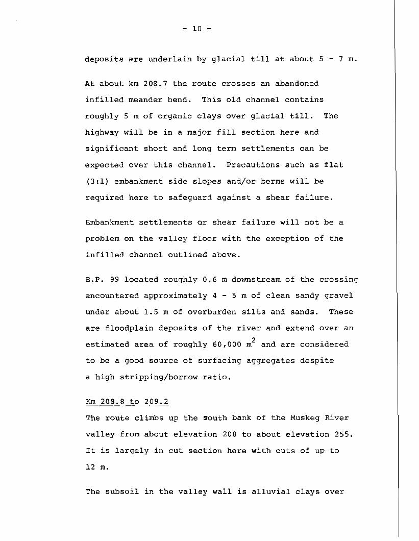
deposits are underlain by glacial till at about 5 - 7 m.
At about km 208.7 the route crosses an abandoned
infilled meander bend. This old channel contains
roughly 5 m of organic clays over glacial till. The
highway will be in a major fill section here and
significant short and long term settlements can be
expected over this channel. Precautions such as flat
( 3 : l ) embankment side slopes and/or berms will be
required here to safeguard against a shear failure.
Embankment settlements or shear failure will not be a
problem on the valley floor with the exception of the
infilled channel outlined above.
B.P. 99 located roughly 0.6 m downstream of the crossing
encountered approximately 4 - 5 m of clean sandy gravel under about 1.5 m of overburden silts and sands. These
are floodplain deposits of the river and extend over an
estimated area of roughly 60,000 m2 and are considered
to be a good source of surfacing aggregates despite
a high stripping/borrow ratio.
Km 208.8 to 209.2
The route climbs up the south bank of the Muskeg River
valley from about elevation 208 to about elevation 255.
section here with cuts of up to It is largely in cut
12 m.
The subsoil in the v .alley wall is alluvial clays over

- 11 -
silty sands. The upper clays are well above optimum;
the lower sands are moist with moisture contents near
10%. Near the top of the valley wall free water was
noted in the upper 5 - 6 m.
Backslopes should remain stable through this cut with
minor short term seepage; material from the cut although
above optimum may be used at the base of the large fills
on the valley floor.
Km 209.2 to 211.0
The route continues to climb above the Muskeg River
valley onto the adjacent upland but at a gradual slope.
Subsoil here is glacial till at depths of 2-3 m with a
silty overlay. Deposits above the till are generally
wet as the till restricts downward drainage. The till
is slightly above optimum.
Borrow pit #101 is located left of and above the right-
of-way at km 210. It is on a relatively well drained
rise and contains useable glacial till which is slightly
above optimum.
Km 211.0 to 2 1 3
This area is flat lying and poorly drained. Till is
shallow (2 - 4 m) with overlays of wet silt, clay, and
peat. Free water is common and moisture contents
average 25 - 30%. There is higher ground to the left
of a with abundant glacial till, however, investigation

- 12 -
for borrow here revealed moisture contents well above
optimum.
Km 213 to 218
The route continues across the till upland which is
slightly rolling, and intersects several small cross-
drainage channels. Glacial till is shallow throughout
with thin 1 - 4 m overlays of silts, clays and sand- silts. These surficial deposits are generally wet and
although there are small rises (notably at km 214.4 and
215.1) and a deep stream channel at km 217.0, where cuts
would enhance the gradeline and borrow requirements,
the materials are unsuitable for any significant cut.
Although glacial till is plentiful here it is generally
well above optimum and unsuitable for borrow. Best
bet for borrow is borrow area #lo4 to the right of
near km 215.1 where moisture contents are variable around
20% and on the average are not significantly above
optimum.
Km 218 to km 225
Beginning near km 218 the route turns south-easterly
and parallels the Petitot River. The upland gradually
rises from elevation 330 near km 218 to elevation 460
near km 225. Glacial till is shallow throughout this
area and the surface is marked by small ridges of till
without distinct orientation to about km 222, and then

- 1 3 -
by larger distinct flutings to km 225. Beginning near
km 119.5 the glacial till becomes drier with moisture
contents consistently near 1 5 % with depth. The upper
0.5 to 1 m is occasionally wet through this area as the
underlying impermeable till does not promote good
drainage, however, cuts are feasible on most ridges.
Borrow is abundant through this section. Five (5 )
borrow sources are available - at km 119.1, 221.2, 222.0,
223.2, and 224.8 - all of which contain glacial clay till near optimum moisture content.
There are some shallow muskegs or peat areas C1 - 2 m
deep) within this area, notably between km 224 and 225
where the flutings are more pronounced and intervening
depressions poorly drained.
Km 225 to 227.0
The route descends from elevation 460 to elevation 4 0 4
across an undifferentiated, heavily treed surface.
Glacial till is shallow throughout with some shallow
surficial sand and sandy gravel ridges near small
streams. The glacial till is near optimum throughout.
Borrow if required is available to the right of P at
km 226.
km 227 to 2 3 1
This is an area of very old burn with some small second
growth spruce and jackpine in drier areas. From km 227

- 14 -
t o about 229 t h e t e r r a i n i s r e l a t i v e l y f l a t and poorly
dra ined . Glacial c l a y till i s wi th in abou t 1 m of t h e
surface, however , t h e upper 1 - 2 m t e n d s t o be w e t of
optimum.
A t km 2 2 9 t h e r o u t e c r o s s e s a broad drainage channel
( 4 0 0 m ) w i th t w o ( 2 ) small streams. Muskeg t o about 2
m can be expec ted i n t h i s d ra inage channe l and shou ld
be wasted. From 2 2 9 . 4 t o 231 t he rou te g radua l ly c l imbs
on poor ly d ra ined t e r r a in . Glacial c l a y till i s shal low
throughout bu t i s wet i n the upper 1 - 2 m.
B o r r o w i s r e a d i l y a v a i l a b l e t h r o u g h t h i s s e c t i o n as the
c l a y till i s shallow throughout and i s a n e x c e l l e n t
cons t ruc t ion ma te r i a l . Four areas were checked fo r
borrow - a till r i d g e a t km 2 2 7 . 1 , and t h ree (3 ) areas
of j a c k p i n e t h a t i n d i c a t e dr ier s u r f a c e materials a t
km 228.5, 228.9 and 230.5. All areas are s u i t a b l e fo r
use - t h e l a t t e r three ( 3 ) areas c o n t a i n some nea r
sur face zones t h a t are s l i g h t l y a b o v e optimum.
km 231 - 235
This area i s a g l a c i a l till p la in cove red w i t h a series
o f pa ra l l e l , na r row, low, till ridges produced by
advanc ing g l ac i e r ice. The long narrow depressions
between t h e l o w r idges are n o t w e l l drained and shal low
p e a t d e p o s i t s are common. Vegetation on t h e r i d g e s i s
l a r g e l y small poplar and jackpine - i n t h e d e p r e s s i o n s
it i s small spruce. The r o u t e crosses t h e s e r i d g e s

- 15 -
roughly at right angles.
Glacial till is shallow throughout. On the ridges it
is dry and cuts are practical. In the flatter areas
it tends to be wet in the upper 0.5 to 1.0 m. In
depressions there is commonly about 1 m of peat which
ideally should be wasted before embankment construction.
A balanced gradeline should be possible through this
area - if not,borrow is readily available in any ridge - three ridges at 2 3 2 . 2 , 2 3 3 . 2 and 2 3 4 . 6 were confirmed
as borrow sources.
Km 2 3 5 to 2 3 8
The route continues across the fluted till plain
described above except that the relief is greater, i.e.
the ridges are broader and higher and the depressions
deeper and wider. There is much more opportunity for
major cuts in the till ridges in this section and a
balanced grade line would seem assured. Major depressions
occur at km 2 3 5 ( 4 0 0 m wide - 1 to 2 m of peat), km
2 3 5 . 4 ( 1 5 0 m wide - 0 . 5 to 1.0 m of peat), km 2 3 7 . 5
(200 m wide - up to 2 m of peat), and km 2 3 7 . 9 (about
150 m wide - up to 1 . 2 5 m of peat). Removal of peat
in these and occasional smaller depressions is
recommended before embankment construction.
A borrow area test-drilled in a stand of jackpine in a
depression at km 2 3 7 . 8 revealed highly plastic silty
clay over soft shale,indicating the mantling till layer

- 16 -
i s r e l a t i v e l y t h i n a b o v e bedrock i n d e p r e s s i o n s .
Km 238 t o km 240
T h i s i s a l a r g e till r i d g e t h a t i s n e i t h e r f l u t e d n o r
drumlinized. The r o u t e climbs f rom e l eva t ion 396 t o about
e l e v a t i o n 420 t h e n r e t u r n s t o e l e v a t i o n 396 a t km 240.
Glacial till i s very shal low throughout and there i s
oppor tun i ty for a major c u t a t the h i g h e r e l e v a t i o n t o
produce a ba lanced grade l ine . In some areas the upper
0.5 t o 1 m of till is w e t of optimum, and an extremely
dense sand was encoun te red a t dep th (2 t o 4 m) n e a r t h e
top o f t h e rise. Auger r e f u s a l was encountered a few
metres i n t o t h i s sand and it is recommended t h a t c u t s
be l imi t ed t o a depth of about 4 m he re t o avoid s i g n i -
f i c a n t p e n e t r a t i o n i n t o t h i s hard sandy stratum.
Km 240 to 245.8
The r o u t e crosses a large h e a v i l y f o r e s t e d rise t h a t i s
n e i t h e r f l u t e d n o r d r u m l i n i z e d b u t i s mantled w i t h
g l a c i a l till. It rises f rom e l eva t ion 400 t o about 475
then drops back t o e l e v a t i o n 445 n e a r km 246. Glacial
till i s n e a r t h e s u r f a c e t h r o u g h o u t - there i s l i t t l e
m i c r o r e l i e f ( i .e. small r i d g e s or depress ions) hence
c u t s e c t i o n s w i l l b e r e l a t i v e l y sha l low, however, a
ba lanced grade l ine should be p o s s i b l e w i t h some d i t c h
borrow. The n e a r s u r f a c e till is g e n e r a l l y n e a r optimum
where t h e t e r r a i n is sloping and reasonably w e l l d r a ined ;
on f l a t t e r poor ly d ra ined areas t h e upper 0.5 t o 1.0 m
- 17 -
of subsoil is wet and well above optimum. There are
few depressions within this section that contain peat.
Additional borrow, if required, is available at km
241.1, 242.6 and 245.6.
Km 245.8 to 247.1
This is a wide valley in which there are two drainage
depressions separated by a low till mound. The first
depression at km 246 is some 300 - 350 m in width and peat deposits are shallow, probably less than 0.5 to
1.0 m. The second depression near km 247 is about
400 m wide and peat deposits of up to 2 m can be ex-
petted. Removal of the peat before embackment con- /
struction is recommended.
The intervening till mound is suitable for cut and
will provide fill for both depressions.
Km 247.1 to 250
The route climbs toward and parallels the Maxhamish
Escarpment here, reaching, a maximum elevation of 534
at km 249.7. For the most part the R.O.W. is on a
cross slope through this section an6 the Kany ridges
which will be in cut section will have high backslopes
on the north and/or east. A balanced gradeline is
possible with the majority of cut sections in glacial
till near optimum moisture content.

- 18 -
Two cut areas may encounter bedrock: At km 249 is a
ridge of 200 m that is composed largely of very hard
or dense sand that may be a soft sandstone. Auger
refusal was reached after very hard drilling in this
ridge at depths of 3 to 6 meters. The ridge is strewn
with huge boulders 1 - 2 + meters in diameter.
Near km 249.7 is a second major ridge of 400 m where
auger refusal was reached abruptly at depths of 3 to 5
meters. Hard bedrock is anticipated in this ridge and
proposed cuts should not be extended below the depths
of auger refusal shown on the borehole logs.
Km 250 to 253
The route skirts the end of the Maxhamish Escarpment
and decends the eastern side to elevation 420 at km 253.
This is an area of significant relief - i.e., ridges - most of which are composed of glacial till and there
will be several major cuts and fills Boulders are
prevalent in the till near the excarpment, however bed-
rock was not encountered. A balanced gradeline can
easily be attained here.
Km 253 to 254.5. (B.C. Border)
This area is relatively flat and some parts have poor
drainage, however glacial till is near the surface and
there are some low till ridges where cuts are possible.
Some shallow peat overlays may be encountered near km

- 19 -
254, however the depth of peat should not exceed 0.5
to 1.0 m. Additional borrow can be obtained here by
widening cuts in the low till ridges or by developing
adjacent borrow pits in the ridges. The glacial clay
till is an excellent construction material and is near
optimum throughout, with the exception of the upper
0.5 m in poorly drained areas.
- 2.3 Ft. Liard Access Road. ( K m 216.8 to Ft. Liard) - 4.0 km From the intersection with the highway, the access road
desends on a gently sloping till upland roughly 1.7 km
to the valley of the Liard River, then drops into the
valley from elevation 294 to elevation 214 by km 2.5,
and then crosses Liard River floodplain deposits to Ft.
Liard.
On the upland the subsoil is glacial till with overlays
of silts, clays, and silt-sands which increase in thick-
ness from about 1 m near the junction to in excess of
8 m near the valley wall. This upland is poorly drained
and the upper soils are generally wet of optimum. A
deep ( 8 m) stream channel crosses the alignment at 0.8 m,
and a shallow cut to about 2.5 m will be possible here
in silt-sand that is wet at the surface (to 0.5 m).
A major cut will be required through the valley wall of
the Liard River - from about km 1.4 to km 2.2. The sub-
soil here is primarily alluvial silt-sand with glacial

- 20 -
till at depth and will be useable embankment material.
The silt-sand is relatively dry with some seepage noted
along the sand-till interface. Cuts terminating in the
silt-sand will result in severe erosion in the ditches
and will require frequent ditch checks; cuts extending
through the silt-sand into the underlying clay till
will likely encounter seepage at the sand-till inter-
face. Backslope stability should not be a problem.
From km 2.2 to Ft. Liard the route is on alluvial flood-
plain deposits of the Liard River, which consists of
stratified clays, silts and sands. There was little
granular material encountered on the floodplain and
materials tend to be very wet at shallow depths. The
route crosses a small abandoned infilled channel near
km 2 . 4 and shallow organics (1 to 1.5 m) may be encount-
ered here and should be removed before embankment con-
struction. Some long term settlement will occur near
km 2 . 4 , however a shear failure is unlikely under the
relatively high fill. Exploratory holes at several lo-
cations on the Liard floodplain along the roadway near
Ft. Liard failed to encounter any granular deposits.
- 2 . 4 Granular Borrow Source at Ft. Liard
The present source of gravel for the settlement of Ft.
Liard is a high terrace along the east side of the Liard
River valley at the confluence of the Petitot River
valley. These deposits are believed to be old glacial

- 21 -
channel deposits that have been partially eroded by
both the Liard and Petitot Rivers in post-glacial
time. The present development of the source by the
settlement is at the base of the terrace on a single
small face. As the top of the terrace in inaccess-
ible with equiment from the settlement, a route to
the area partially utilizing existing seismic lines
was cleared, beginning near km 219 on the highway.
This route is some 5 km in length. The granular area
was designated Borrow Area #113 and 17 test holes
were drilled.
There is good quality granular aggregates here in
quantity. The lower part of the terrace nearest the
settlement (test holes #1 to #6) is apparently reserved
for use by settlement of Ft. Liard. Of the remaining
area test drilled, the best quality granular material
was encountered in the vicinity of holes #13, #14 and
#15. These holes were terminated in gravel at depths
of 9 to 11 m with 2 - 3 m of overburden, and were
spaced at intervals of about 100 m indicating a sub-
stantial volume of material. The holes were located
parallel to and within about 80 m of the Petitot, hence
the area is limited by the river on the south but is
open to the north. The volume of material available
is estimated to be in excess of 400,000 cubic meters,
however additional drilling should be carried out to
define the deposit.

- 22 -
There is one additional feature that is considered, from
air photo analysis, to have some potential as an aggre-
gate source. This is a high terrace along the Petitot
River located due south of the highway at kilometer 230.
Test drilling was not attempted due to a steep slope on
the valley wall leading to the terrace. Test pitting
by hand is recommended here to assess the area as an ag-
gregate source.

CLASSIFICATION SYSTEM
P e r m a f r o s t g r o u n d i ce o c c u r s i n t h r e e b a s i c c o n d i t i o n s
i n c l u d i n g n o n - v i s i b l e , v i s i b l e ( less t h a n 25 Rm in
t h i c k n e s s ) and c l e a r i ce .
A. N o n - v i s i b l e - N
Nf - p o o r l y b o n d e d or f r i a b l e f r o z e n s o i l
Nbn
be
- well bonded s o i l , n o e x c e s s ice
- w e l l bonded soil, excess ice: .
B. V i s ib l e - V ( less than25mm t h i c k )
V - i n d i v i d u a l i c e c r y s t a l s or i n c l u s i o n s x
vC
'r
vS
- i ce c o a t i n g s o n p a r t i c l e s
- random or i r r e g u l a r l y o r i e n t e d ice f o r m a t i o n s . - s t r a t i f i e d o r o r i e n t e d i ce f o r m a t i o n s
C . V i s i b l e Ice - ( g r e a t e r t h a n 25mm t h i c k )
Ice - i c e w i t h s o i l i n c l u s i o n s
Ice + s o i l - i c e w i t h o u t s o i l i n c l u s i o n s

.
MODlFlLD UNIFIED CLASSIFICAlION S Y S T E M F O R 5011.5
MAJOR DIVISION
._.-".I ---
"--t .
"---"
T
"
i :- I i
I
5M
"
CI
OK
?ICIII iI lY CHAR1

a
GEOTECHNICAL NOTES ON LIARD HIGHWAY MILE 40-67, KM 205-254,
MILE 34 BORROW PIT AND FORT LIARD ACCESS ROAD.
Mile 34 Pit run gravel: The pit is outlined on the basis of two holes only while the access road merits 5 holes although for winter use only. This represents an imbalance in data collection. Addition- al holes at the proposed pit extremeties would be prudent. The plan for pit development appears acceptable providing that addition- al drilling confirms the presence of suitable material throughout the proposed area. General - Obtaining data on clays and silts as fines is economically sound but there may be some circumstances where the separation would be prudent for both engineering and environmental assessment. These circumstances would be primarily where the material being proposed for use is predominantly sand or gravel but a fines component of 10-25% is present. The geotechnical report by R.D. Cook has a minor inconsistency which should be noted in case it should translate into excavation; on p. 3 it is noted that drilling was not undertaken within 90m of lakes or streams and yet on p.21 "holes were located parallel to and within about 80m of the Pettitot" ... Access Road Culvert - Access Rd. 4.020 shows from going both ways. KM.3 - Campsite area is not completely on the mosaic nor is there any indication of drilling to determine the suitability of the sub- strata. The reader is left to assume that the site has been checked out as being suitable. What arrangements for water supply and disposal are acticipated? Mile 40-65 - No grain size data 40-1 to 4 incl.
No grain size data 41 Mile 43. Cut at C5 and C6 - no grain size at C5 - materials may be in permafrost as stream at the base appears to be beaded suggesting thawing of ground ice lenses. Hole 44-5 - No data recorded except depth of hole.

- 2 -
Hole 4 7 4 and 6 i n g e n e r a l l y " h i g h f i n e s ' ' t e r r a i n
and a t l o c a t i o n o f t w o m i n o r c u t s b u t n o g r a i n s i z e d a t a .
Holes 48-5-6-7 i n area o f c u t a n d h i g h l y v a r i a b l e materials (70-30 t o 23-77) b u t n o g r a i n s i z e from
h o l e 6 . S l o p e c o u l d c o n t a i n p e r m a f r o s t p o c k e t .
S t ream a t 48.2583 appears t o be beaded suggest ing perma-
f r o s t w i t h ice l e n s e s i n v i c i n i t y . Mile 49-C-9 - m a i n p a r t of c u t a n d y e t n o g r a i n s i z e d a t a . Mile 50-C-6 - as above.
Mile 50-C-8 - Located w i t h i n c u t a n d s a t u r a t e d l a y e r a t 8 ' b u t no g r a i n s i z e d a t a . B o t h C-7 and C-9 h a v e s u b s t a n t i a l f i n e s .
C u l v e r t i n t a k e a t 51-2733 i s shown 1 . 5 f t . a b o v e c u r r e n t g r o u n d level. Mile 51-C-6 - Material from c u t i s medium p l a s t i c - may no t be
s u i t a b l e f o r a a d j a c e n t f i l l .
Mile 52-C-12 - Material a t l e v e l o f c u t i s medium p l a s t i c a n d
a b o v e p l a s t i c l i m i t - may p o s e s t a b i l i t y o r main tenance p roblems
as on one of t h e s t e e p e r g r a d e s , u n l e s s a d d i t i o n a l p r e c a u t i o n s
are t a k e n .
Mile 53-2840 - C e n t r e l i n e shown of: t h e c l e a r e d ROW.
Mile 54 - C u l v e r t a t 2858 shown w i t h i n t a k e 5 f t . a b o v e c u r r e n t
stream bed. A ponding problem?
Mile 55 - C u l v e r t a t 2915 shown w i t h i n t a k e 8 . 5 f t . a b o v e c u r r e n t
stream bed. Another ponding problem?
Mile 55 2943 - Major 40 f t . d e p r e s s i o n w i t h no p r o v i s i o n f o r cross d r a i n a g e .
Mile 58 a t 3114.5 - C u l v e r t shown b u r i e d w i t h r e p s e c t t o g r o u n d level - why? Mile 59 3130 - C u t s u r f a c e j u s t i n a l o w p l a s t i c i n t e r v a l a t 59-c-4. Mile 6 2 3294 - 3 6 " c u l v e r t i n s e t 2 4 " below g r o u n d s u r f a c e - t o o d e e p ? Mile 6 2 3317 - 3 0 " c u l b e r t i n s e t 1 8 " b e l o w g r o u n d s u r f a c e - t oo deep?
V

- 2 -
Hole 47-4 a n d 6 i n g e n e r a l l y "high f i n e s " t e r r a i n a n d a t l o c a t i o n
of t w o minor c u s

L
- 3 -
Mile 65 Cut a t 3462 : p roposed cu t su r f ace i s i n a p l a s t i c c l a y
s i l t which may g o o v e r t h e p l a s t i c l i m i t when w e t . Mile 65 C-10 and C - 1 1 low t o medium p l a s t i c materials may n o t be
s u i t a b l e f o r f i l l . N o g r a i n s i z e data f o r t h e s e two h o l e s . Mile 6 6 Holes 1 and 2 d o n o t p e n e t r a t e s u f f i c i e n t l y below p r o j e c t e d
g r a d e . T h i s i s p a r t i c u l a r l y i m p o r t a n t as t h e materials are p l a s t i c
and no g ra in s i z e d a t a are g i v e n .
Mile 66 - A p p r o a c h c u t t o B l a c k s t o n e R i v e r . N o g r a i n s i z e d a t a d e s p i t e i d e n t i f y i n g a p l a s t i c i n t e r v a l i n e a c h o f t h e t h r e e h o l e s . The v a r i a b i l i t y of t h e material c o u l d a l s o c a u s e a d d i t i o n a l p r o -
blems due t o d i f f e r e n c e s i n p e r m e a b i l i t y . Holes 1 0 and 11 y i e l d less p e n e t r a t i o n o f t h e p r o p o s e d c u t s u r f a c e t h a n i s d e s i r a b l e f o r a s s e s s i n g s t a b i l i t y a n d e r o s i o n p o t e n t i a l .
D.M. B a r n e t t , Env i ronmen ta l Geo log i s t .
O c t . 6/78