GypLyner UNIVERSAL (W) 120408:Layout 1 - gyproc.ie GYPLYNER WALLS.pdf · Moy Isover Insulation For...
16
208 GypLyner™ GypLyner™ (walls) Metal framed wall lining system GypLyner™ is a cost-effective, virtually independent metal frame drylining system for lining walls. General purpose and suitable for all internal non-loadbearing applications. This system is compatible with, and uses common components of, GypLyner™ ceiling lining and GypLyner™ ENCASE steel encasement system. May 2008 www.gypsum.ie 6
Transcript of GypLyner UNIVERSAL (W) 120408:Layout 1 - gyproc.ie GYPLYNER WALLS.pdf · Moy Isover Insulation For...

208
Gyp
Lyn
er™
GypLyner™ (walls)
Metal framed wall liningsystem
GypLyner™ is a cost-effective,virtually independent metal frame drylining system for lining walls.General purpose and suitable for allinternal non-loadbearing applications. This system is compatible with, and uses commoncomponents of, GypLyner™ ceilinglining and GypLyner™ ENCASE steelencasement system.
May 2008
www.gypsum.ie
6
GypLyner UNIVERSAL (W)_120408:Layout 1 26/05/2008 15:31 Page 208

209
Gyp
Lyn
er™
Key facts
● Corrects background irregularities
● Minimal connection to the structure
● Can satisfy National Building Regulations on
thermal performance
● Can be used to upgrade the sound resistance and
thermal insulation
● Versatile, general purpose lining
● Little or no background preparation needed
● Commonality of ceiling and wall lining
components
May 2008
1
Gypframe GL2 or GL9 Bracket
Gypframe GL1 Lining Channel
Gypframe GL8 Track
1
2
23
3
3
Technical support: T 01 629 8400 E [email protected]
6
GypLyner UNIVERSAL (W)_120408:Layout 1 26/05/2008 15:31 Page 209

ComponentsGyproc board products
Gypframe GL2 Bracket
Length 195mm flat (max 75mm stand-off from wall)
Gypframe metal products
Gypframe GL1 Lining Channel
Gyp
Wal
l™ CL
ASS
IC
210
Gyp
Lyn
er™
1 Moisture resistant boards are specifed in intermittent wet use arease.g. shower areas, bathrooms and kitchens.
2 Also available in DUPLEX grades where a vapour check is required.
May 2008
Gypframe GL3 Channel Connector
For joining GL1 Lining Channels.
Gypframe GL8 Track
Gyproc Thermal laminate
Width 600, 1200mm
Gyproc WallBoard1,2
Thickness 12.5, 15mm
Width 1200mm
Gyproc SoundBloc
Width 1200mm
Gyproc DuraLine1
Thickness 13.5, 15mm
Width 1200mm
Gypframe GL9 BracketLength 295mm flat (max 125mm stand-off from wall)
www.gypsum.ie
6
GypLyner UNIVERSAL (W)_120408:Layout 1 26/05/2008 15:31 Page 210
Gyp
Lyn
er™
211
Gyp
Lyn
er™
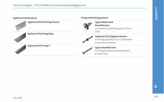
Fixing and finishing products
Gyproc Wafer Head
Drywall Screws
For metal-to-metal fixing up to 0.79mm
thick
May 2008
Gypframe GL11 GypLyner Anchors
For fixing Gypframe GL2 or GL9 Brackets
to concrete / masonry
Gypframe 99 FC 50 Fixing Channel
Gypframe metal products
Gypframe GFS1 Fixing Strap
Gypframe GFT1 Fixing 'T'Gyproc Drywall Screws
For fixing boards to stud framing up to
0.79mm thick
Technical support: T 01 629 8400 E [email protected]
6
GypLyner UNIVERSAL (W)_120408:Layout 1 26/05/2008 15:31 Page 211

ComponentsFixing and finishing products Fixing and finishing products
Gyproc jointing materials
For a seamless finish.Gyp
Wal
l™ CL
ASS
IC
212
Gyp
Lyn
er™
May 2008
Gyproc edge beads
Protecting and enhancing board edges.
Gyproc Control Joint
To accomodate structural movement.
Gyproc Skimcoat, Gyproc Carlite Finish,
Gyproc Board Finish,
To provide a plaster skim finish.
Moy Isover Insulation
For enhanced acoustic and thermal
performance.
Gyproc Sealant
Sealing air paths for optimum sound
insulation.
www.gypsum.ie
6
GypLyner UNIVERSAL (W)_120408:Layout 1 26/05/2008 15:31 Page 212

Gyp
Lyn
er™
213
Gyp
Lyn
er™
Construction tips
● Estimated construction time 3m2 / man hour - ready for finishing
● Depth of the cavity is determined by the fixing brackets. Allow a stand-off of 25mm - 75mm, plus the lining
thickness, for a Gypframe GL2 Bracket and 25mm - 125mm, plus the lining thickness, for a Gypframe GL9 Bracket
● Keep the drylining cavity closed to prevent downgrading the thermal performance - where required apply a
continuous band of Gyproc Compound or Gyproc Sealant to the perimeter of external walls, around service
penetrations, openings, junctions and around the perimeter of suspended timber floors
● Brackets to be fixed at a maximum of 800mm vertical centres
● Use full height boards where possible - if joints are unavoidable, position them above suspended ceilings or below
access floor level where possible
● Support horizontal joints with Gypframe GFS1 Fixing Strap, Gypframe 99FC50 Fixing Channel, or Gypframe GFT1
Fixing ‘T’ (where specified).
● Form vertical cavity barriers, where specified, in long runs of lining
May 2008
Technical support: T 01 629 8400 E [email protected]
6
GypLyner UNIVERSAL (W)_120408:Layout 1 26/05/2008 15:31 Page 213

Gyp
Wal
l™ CL
ASS
IC
214
Gyp
Lyn
er™
May 2008
• Use a straight edge (e.g. GypframeGL1 Lining Channel) to determine themaximum undulation in the wall orservice protrusion. This will determinethe minimum cavity depth.
• Determine cavity depth required andmark chalk lines to floor and ceiling toindicate positioning of Gypframe GL8Track.
• Fix Gypframe GL8 Track to perimeters,with the longer leg towards the lining,at 600mm centres using appropriatefixings.
2 3
Installation
1
www.gypsum.ie
6
GypLyner UNIVERSAL (W)_120408:Layout 1 26/05/2008 15:31 Page 214

Gyp
Lyn
er™
215
Gyp
Lyn
er™
May 2008
6
• Mark vertical lines on the wall at600mm intervals (450mm intervals for900mm width boards) to indicatebracket fixing centres.
• Mark horizontal lines at 800mmcentres to determine individual bracketposition.
• Position each bracket, ribs to the wall,and fix through bracket slot into themasonry wall using a Gypframe GL11GypLyner Anchor.
• Cut Gypframe GL1 Lining Channels tosize and round-off ends with tin snipsfor an easier fit.
• Extend Gypframe GL1 Channels,where required, by engaging channelends over a Gypframe GL3 ChannelConnector.
Additional Gypframe GL1 LiningChannels may be required to pick up fixings for subsequent adjacent linings.
• Friction fit Gypframe GL1 LiningChannel into the track.
• Bend bracket legs forward and fixeach leg to the channel using a GyprocWafer Head Drywall Screw. Insert screwthrough the hole in the bracket nearestto the back of the channel (SeeConstruction details , Figure 18).
Avoid exerting any backwards orforwards pressure on the channelswhen screw-fixing the brackets,otherwise a straight and true liningsurface may not be achieved.
NB
NB
4 5
Technical support: T 01 629 8400 E [email protected]
6
GypLyner UNIVERSAL (W)_120408:Layout 1 26/05/2008 15:31 Page 215

Gyp
Wal
l™ CL
ASS
IC
216
Gyp
Lyn
er™
98
• Bend back protruding bracket legs tosit clear of the channel face.
• Fix Gypframe GFS1 Fixing Strap or GFT1Fixing ‘T’ to back horizontal board joints ifrequired.
Internal angles
• Position a Gypframe GL1 LiningChannel tight into the corner in order toprovide support for the lining.
• Bend one bracket leg across the faceof the Gypframe GL1 Lining Channeland fix with a Gyproc Wafer HeadDrywall Screw to secure and restrain thechannel at the corner position.
Board fixing
• Fix boards to all framing members at300mm centres using Gyproc DrywallScrews from top to bottom.
• Lightly butt boards, inserting screwsnot closer than 10mm from boundedges and 13mm from cut edges.
Select the appropriate length offixing to provide a nominal 10mm penetration into the steel framing.
NB
May 2008
7
www.gypsum.ie
6
GypLyner UNIVERSAL (W)_120408:Layout 1 26/05/2008 15:31 Page 216

121110
Gyp
Lyn
er™
217
Gyp
Lyn
er™
• Perpendicular linings to be fixedthrough previous plasterboard into theGypframe GL1 Lining Channel behind.
• Locate Gypframe GL8 Track tight to thewall at the corner position and fixthrough the lining into the channel.
Openings
• Position a Gypframe GL1 LiningChannel each side of the opening whilecompensating for the thickness of theplasterboard to be fixed into the reveal.
• Fix to Gypframe GL8 Track at head andbase with Gyproc Wafer Head DrywallScrew.
• Continue boarding, fixing boards to allframing members.
• Install cut and bent Gypframe GL8 Trackto form the head of the opening and fix tothe side of the Gypframe GL1 Channelsusing two Gyproc Wafer Head DrywallScrews.
• Position a short length of GypframeGL1 Lining Channel above the openingto support vertical board joints and fixusing two Gyproc Wafer Head DrywallScrews.
• Maximum 600mm centres forGypframe GL1 Channels must bemaintained.
May 2008
Technical support: T 01 629 8400 E [email protected]
6
GypLyner UNIVERSAL (W)_120408:Layout 1 26/05/2008 15:31 Page 217

Gyp
Wal
l™ CL
ASS
IC
218
Gyp
Lyn
er™
1514
• Fix Gyproc edge bead to the perimeterof the window frame to provide edgerestraint and protection to the reveal andsoffit linings.
May 2008
• Cut reveal and soffit boards to width,locate into the perimeter edge bead andfix into the Gypframe GL9 Channel andGypframe GL8 Track.
• Fix boards to complete drylining at theopening.
•Where openings occur in the run oflining, cut board around the opening toavoid a joint directly in line with edge ofopenings.
• Ensure vertical board joints above dooropes are supported by Gypframe GL1Channels.
13
www.gypsum.ie
6
GypLyner UNIVERSAL (W)_120408:Layout 1 26/05/2008 15:31 Page 218

Gyp
Lyn
er™
219
Gyp
Lyn
er™
Insulation
• If Moy insulation is specified, installprogressively as boarding proceeds.
The insulating backing of GyprocThermal laminates should not be chasedto accommodate services. PVC coveredcables must not come into contact withpolystyrene insulation. Use suitableisolation methods (conduit or capping)
Service installations
•The drylining cavity facilitates theincorporation of services. Fix pipes andconduits in position before installing theframing.
• All services should be installed inaccordance with all available standards,guidelines and recommendations.
May 2008
16 17
NB
Technical support: T 01 629 8400 E [email protected]
6
GypLyner UNIVERSAL (W)_120408:Layout 1 26/05/2008 15:31 Page 219

Construction details
1
3
2
Gypframe GL2 or GL9 Bracket
Gypframe GL1 Lining Channel
Gyproc Wafer Head Drywall Screw
Gypframe GL8 Track123
4
Gyp
Wal
l™ CL
ASS
IC
220
Gyp
Lyn
er™
2
4
18Channel fixing (Gypframe GL9 Bracket shown at maximum
extension) 19 Base detail
May 2008
125mm (maximum
stand-off) to face of
channel
www.gypsum.ie
6
GypLyner UNIVERSAL (W)_120408:Layout 1 26/05/2008 15:31 Page 220

Gyp
Lyn
er™
221
Gyp
Lyn
er™
Gypframe GL1 Lining Channel
Gypframe GL8 Track
Gyproc Sealant
Gypframe GL2 or GL9 Bracket
Gypframe GL11 GypLyner Anchor
Wall structure
Gyproc plasterboard lining
Proprietary window unit
Moy Isover Insulation
(subject to requirements)
123
45
3
1
2
21 Internal angle (perimeter sealing to external wall)
May 2008
6
7
8
9
4
5
6
7
Technical support: T 01 629 8400 E [email protected]
6
20 Window reveal
9
6
8
3
7
4
1
7
3
GypLyner UNIVERSAL (W)_120408:Layout 1 26/05/2008 15:31 Page 221

Junction details
Gypframe GL2 or GL9 Bracket
Gypframe GL1 Lining Channel
Gyproc plasterboard lining
Wall structure123
4
Gyp
Wal
l™ CL
ASS
IC
222
Gyp
Lyn
er™
22 External angle
May 2008
1
3
2
2
4
www.gypsum.ie
6
GypLyner UNIVERSAL (W)_120408:Layout 1 26/05/2008 15:31 Page 222

223
Gyp
Lyn
er™
May 2008
Technical support: T 01 629 8400 E [email protected]
6
GypLyner UNIVERSAL (W)_120408:Layout 1 26/05/2008 15:31 Page 223