
GV-AS200 Controller -...
38
Before attempting to connect or operate this product, please read these instructions carefully and save this manual for future use. GV-AS200 Controller Hardware Installation Guide
Transcript of GV-AS200 Controller -...

Before attempting to connect or operate this product,please read these instructions carefully and save this manual for future use.
GV-AS200 ControllerHardware Installation Guide

© 2008 GeoVision, Inc. All rights reserved. Under the copyright laws, this manual may not be copied, in whole or in part, without the written consent of GeoVision. Every effort has been made to ensure that the information in this manual is accurate. GeoVision is not responsible for printing or clerical errors. GeoVision, Inc. 9F, No. 246, Sec. 1, Neihu Rd., Neihu District, Taipei, Taiwan Tel: +886-2-8797-8377 Fax: +886-2-8797-8335 http://www.geovision.com.tw Trademarks used in this manual: GeoVision, the GeoVision logo and GV series products are trademarks of GeoVision, Inc. Windows and Windows XP are registered trademarks of Microsoft Corporation. June 2008

I
Contents
1. Introduction.......................................................................................................... 1
1.1 Main Features.............................................................................................................1 1.2 Models ........................................................................................................................1 1.3 AS200 Module Layout ................................................................................................2
2. AS200 Controller Work Modes ........................................................................... 3
3. Installation and Wiring ........................................................................................ 5
3.1 Connecting AS200 Controller to the PC .....................................................................5 3.2 Connecting Inputs.......................................................................................................6 3.3 Connecting Outputs ....................................................................................................8 3.4 Connecting Card Readers ........................................................................................10 3.5 Connecting the Power ..............................................................................................13
4. AS200 Controller Operation.............................................................................. 15
4.1 How to reboot AS200 Controller ...............................................................................15 4.2 How to reset AS200 Controller to factory defaults....................................................15 4.3 Status LEDs..............................................................................................................16
5. ASKeypad........................................................................................................... 17
5.1 Installation.................................................................................................................17 5.2 Setting Parameter.....................................................................................................18 5.3 Displaying System Information .................................................................................18
6. AS200E ............................................................................................................... 21
6.1 Installing AS200E on a Network ...............................................................................21 6.1.1 Fixed IP Connection ......................................................................................21 6.1.2 DHCP Connection .........................................................................................23
6.1.2.1 Connection over LAN ......................................................................24 6.1.2.2 Connection over Internet.................................................................26
6.2 System Settings........................................................................................................29 6.2.1 System Setup ................................................................................................29 6.2.2 Updating Firmware ........................................................................................30 6.2.3 Changing Login ID and Password .................................................................31 6.2.4 Setting Controller ID and Work Mode............................................................31
7. Specifications .................................................................................................... 33
8. Troubleshooting ................................................................................................ 34

II
Introduction
1
1
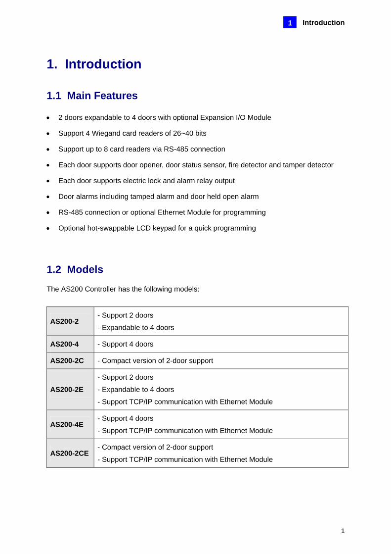
1. Introduction
1.1 Main Features
• 2 doors expandable to 4 doors with optional Expansion I/O Module
• Support 4 Wiegand card readers of 26~40 bits
• Support up to 8 card readers via RS-485 connection
• Each door supports door opener, door status sensor, fire detector and tamper detector
• Each door supports electric lock and alarm relay output
• Door alarms including tamped alarm and door held open alarm
• RS-485 connection or optional Ethernet Module for programming
• Optional hot-swappable LCD keypad for a quick programming
1.2 Models
The AS200 Controller has the following models:
AS200-2 - Support 2 doors
- Expandable to 4 doors
AS200-4 - Support 4 doors
AS200-2C - Compact version of 2-door support
AS200-2E - Support 2 doors
- Expandable to 4 doors
- Support TCP/IP communication with Ethernet Module
AS200-4E - Support 4 doors
- Support TCP/IP communication with Ethernet Module
AS200-2CE - Compact version of 2-door support
- Support TCP/IP communication with Ethernet Module

2
1.3 AS200 Module Layout
ECE
ECE
ECE
ECE
ECE
1 2 3 4 5 6 7 8
ON
ECE
1
2
3
4
5
6
7
8
ON
FireTam
perG
ND
Door A
FireTam
perG
ND
Door B
(Special Terminal)
12VD
0D
1G
LR
LBZG
ND
Wiegand A
12VD
0D
1G
LR
LB
ZG
ND
Wiegand B
12VD
0D
1G
LR
LB
ZG
ND
Wiegand C
12VD
0D
1G
LR
LB
ZG
ND
Wiegand D
TEM
P2
12V+-G
ND
Reset
DC12V- +
1111
External I/O
Door A Door B
Doo
r CD
oor D
Ethernet
GN
D-+12V
TEMP1
Fuse1
Default EN
Reset EN
Default
Connect to A
S-Keypad
Fuse2
Door A Door B Door C Door D
AS200
DIP
5 6 7 8
ForceFireB
uttonS
ensor
ON
1 2 3 4
ForceFireB
uttonS
ensor
Door(A,B,C,D)Input type
ON:NC typeOFF:NO type
Input Contact type
EC
E.1
.
12V
Volta
ge In
put
EC
E.1
.
Dry
Con
tact
Inpu
t
Door Relay type
NC ON
Green: ON:Door Open Flash:Hold Open AlarmYellow: ON:Open Door Button ActiveRed: ON:Fire Alarm Flash:Force Alarm
Green: ON:Door Open Flash:Hold Open AlarmYellow: ON:Open Door Button ActiveRed: ON:Fire Alarm Flash:Force Alarm
Green: ON:Door Open Flash:Hold Open AlarmYellow: ON:Open Door Button ActiveRed: ON:Fire Alarm Flash:Force Alarm
DIP
5 6 7 8
Tamper
FireB
uttonS
ensor
ON
1 2 3 4
Tamper
FireB
uttonS
ensor
Door(A,B,C,D)
ON:NC typeOFF:NO type
Input type Input Contact type
ECE
.1.
12V
Vol
tage
Inpu
t
ECE
.1.
Dry
Con
tact
Inpu
t
Door Relay type
NC ON
Power -
Power +
Alarm -
Alarm +
Door -
Door +
Urgent 2
Urgent 1
Button 2Button 1Sensor 2Sensor 1
Power -
Power +
Alarm -
Alarm +
Door -
Door +
Urgent 2
Urgent 1
Button 2Button 1Sensor 2Sensor 1
Input Output
DoorB
Input Output
DoorA

AS200 Controller Work Modes
3
2
2. AS200 Controller Work Modes The AS200 Controller supports the four types of work modes for door-access control:
• One-way control: A door is equipped with one card reader for entry. For example, a user may swipe a card to open the door of office and push a button to leave from the same door.
• Two-way control: A door is equipped with two card readers. The outer reader is defined as entry reader and the inner reader is defined as exit reader. For example, a user may swipe a card to gain access to a laboratory, and swipe a card to exit from the same door.
• Mixed control: A mix of One-Way and Two-Way Control applications. Some doors are equipped with one card reader for entry and some doors are equipped with two card readers for entry and exit. For example, a building includes both office and laboratory applications.
• One-way traffic: Two doors are applied for entry and exit separately. For example, in a parking lot, a user may swipe a card at the entrance and swipe a card again at the exit.
By default the AS200 Controller is set to one-way control. For the applications requiring more than 2 doors, the Expansion I/O Module can be added to expand two additional doors.

4

Installation and Wiring
5
3
3. Installation and Wiring Please open the AS200 Controller cabinet and wire the necessary connections to the AS200 Controller module.
3.1 Connecting AS200 Controller to the PC
OR
GV-HUB /GV-COM /
GV-NET/IO Card V3.1
GND-+12V
RS-485
PC
The connected computer is used to program the ASServer. The communication mode can be either RS-485 or Ethernet. The default value is set to RS-485 with 57600bps. For Ethernet mode, an optional Ethernet module is required. For RS-485 connection to the PC, the GV series products for RS-485/RS-232 converter can be applied, such as GV-Hub, GV-COM and GV-NET/IO Card V3.
Note:
• The AS200 Controller is not compatible with GV-NET Card and GV-NET/IO Card of versions earlier than V3.
• The maximum of 16 AS200 Controllers can connect to the same COM port.

6
3.2 Connecting Inputs
The AS200 Controller provides four digital inputs:
- Button inputs, e.g. door opener - Sensor inputs, e.g. door status sensor - Fire inputs, e.g. fire detector - Tamper inputs, e.g. tamper detection sensor
The factory defaults of Button inputs and Sensor inputs are set to wet contact; the defaults of Fire inputs and Tamper inputs are set to dry contact.
• The inputs are located at the bottom of the AS200 Controller module.
Input
Button 2Button 1Sensor 2Sensor 2
Input Contact Switch
Input Contact Switch
• The inputs are located at the top right of the AS200 Controller module.
Doo
r AD
oor B
(Spe
cial
Ter
min
al)
Button Inputs The Button inputs can connect to a door opener device for entry or exit. By using the “Input Contact Switch” next to the Button inputs, set your Button device to dry or wet contact. Refer to Input Contact Switches below.
Senor Inputs The Sensor inputs can connect to a door’s micro switch for door status monitoring. Triggering the Sensor inputs can generate the two alarm states:

Installation and Wiring
7
3
• Tamper alarm- when the door is forcibly opened by unauthorized persons. • Door held open alarm- when the door is open for a period exceeding the lock strike
programmed open time. By using the “Input Contact Switch” next to the Sensor inputs, set your Sensor device to dry or wet contact. Refer to Input Contact Switches below.
Fire Inputs The Fire inputs can connect to a fire detection device such as smoke detector. The default setting is dry contact.
Tamper Inputs The Tamper inputs can connect to a tamper switch to detect unauthorized opening of the door. The default setting is dry contact.
Input Contact Switches For “Sensor inputs” and “Button inputs”, you can use the Input Contact Switches to change the contact type.
ECE ECE1
1
1
Dry Contact Default: Wet Contact(12 Voltage Input)
Input NO and NC Switches Using the switches to set the four digital inputs for NO (normally open) or NC (normally closed) mode.
ECE
DIP
5 6 7 8
Tamper
FireB
uttonS
ensor
ON
1 2 3 4
Tamper
FireB
uttonS
ensor
Door(A,B,C,D)
ON:NC typeOFF:NO type
Input typeECE
1 2 3 4 5 6 7 8
ON

8
3.3 Connecting Outputs
The AS200 Controller provides three relay outputs:
- Door outputs +/-, e.g. electronic lock - Alarm outputs +/-, e.g. siren or bell - Urgent outputs, e.g. emergency door release button
Urgent 2
Alarm -Power +Power -
Alarm +Door -Door +
Urgent 1
Door Relay Switch (2-in-1 set)
Output
This figure illustrates the wiring configuration for output relays when the door relay is set to be normally closed.
Door Relay of Normally Closed
FIREFIREFIRE

Installation and Wiring
9
3
This figure illustrates the wiring configuration for output relays when the door relay is set to be normally open.
Door Relay of Normally Open
FIREFIREFIRE
Door Outputs The Door outputs can operate a door-locking device such as electromechanical strikes and can be configured to operate in NC (normally closed) or NO (normally open) modes. To configure the NO mode, push one set of two Door Replay Switches downward. To configure the NC mode, push the switches upward.
NO (Default)NC
Alarm Outputs The Alarm outputs can connect to an alarm annunciator such as siren or bell.
Urgent Outputs The Urgent outputs can connect to a button or device that forcibly open a door without reading a card.

10
Note:
1. If your output devices require more than 12V DC, connect the necessary power directly to the power terminals without using the AS200 Controller power converter.
2. The door-locking and alarm devices must use the same voltage, or device damage may occur.
3. If the door-locking device (Door +/-) is a grounded circuit type (NC), the emergency door release device (Urgent 1/2) must be configured as the same circuit type as well.
4. If the emergency door release device (Urgent 1/2) is not connected and the door relay is normally closed, please close the Urgent circuit.
5. If the door-locking device (Door +/-) and alarm (Alarm +/-) are the relay outputs of dry contact, please:
- chain Urgent 1 and Door + together
- chain Alarm + and Power + together
3.4 Connecting Card Readers
The AS200 Controller supports two types of card readers: Wiegand and RS-485 interfaces. The two types of card readers can be used together to operate with the AS200 Controller.
FIREFIREFIRE

Installation and Wiring
11
3
12V
D0D1
GL
RL
BZ
GND
Wie
gand
D
12V
Wiegand Card Reader
Card Reader
AND
-
+
RS-485
GND
Wiegand
Wiegand Devices The AS200 Controller supports up to 4 Wiegand inputs (Wiegand A, B, C, D) for connection of Wiegand devices ranging from 26 to 40 bits. Please consult your Wiegand device documentation for wiring. The pin assignments for the Wiegand terminals are described as below:
Pin Function
12V 12V Power Supply
D0 Wiegand Data-0
D1 Wiegand Data-1
GL Green LED
RL Red LED
BZ Beeper
GND GND of the Power Supply
The maximum distance the Wiegand signal will travel is 500 feet.
RS-485 Devices For long-distance connection and non-Weigand card readers, you can use the RS-485 connectors. Via RS-485 connection, up to 8 card readers can be supported.
Note: For RS-485 connection, you must set “GV-Reader ID” to Extended Wiegand by using ASKeypad. See 5.2 Setting Parameter.

12
Corresponding Tables between Doors and Card Readers The following tables show how and where each card readers should be placed based on different work modes. Wiegand Card Readers The default 2-door applications: Door A and Door B
Door A Door B Work Mode
In Out In Out One-way control Wiegand A Button inputs Wiegand B Button inputs Two-way control Wiegand A Wiegand C Wiegand B Wiegand D
Mixed control Wiegand A Button inputs Wiegand B Wiegand D One-way traffic Wiegand A Non Non Wiegand B
Using an optional Expansion I/O Module to add two additional doors: Door C and Door D:
Door C Door D Work Mode In Out In Out
One-way control Wiegand C Button inputs Wiegnad D Button inputs Two-way control Non Non Non Non
Mixed control Wiegand C Button inputs Non Non One-way traffic Wiegand C Non Non Wiegand D
RS-485 Card Readers The default 2-door applications: Door A and Door B
Door A Door B Work Mode
In Out In Out One-way control RS-485 No. 0 Button inputs RS-485 No. 1 Button inputs Two-way control RS-485 No. 0 RS-485 No. 2 RS-485 No. 1 RS-485 No. 3
Mixed control RS-485 No. 0 Button inputs RS-485 No. 1 RS-485 No. 3 One-way traffic RS-485 No. 0 Non Non RS-485 No. 1
Using an optional Expansion I/O Module to add two additional doors: Door C and Door D
Door C Door D Work Mode In Out In Out
One-way control RS-485 No. 2 Button inputs RS-485 No. 3 Button inputs Two-way control RS-485 No. 4 RS-485 No. 5 RS-485 No. 6 RS-485 No. 7
Mixed control RS-485 No. 2 Button inputs RS-485 No. 6 RS-485 No. 7 One-way traffic RS-485 No. 2 Non Non RS-485 No. 3
Note: The Work Mode is set by ASKeypad or via Ethernet connection when the Ethernet module is installed.

Installation and Wiring
13
3
3.5 Connecting the Power
After all wiring is complete, power on the AS200 Controller.
• Plug one end of the supplied power cable into the 6-pin connector on the power converter, and the other end into the three power connectors on the AS200 Controller module:
- Power Connectors: 12V DC +/ - - Door A Power Connectors: Power +/- - Door B Power Connectors: Power +/-
The black line of the power cable represents negative (-); the red line of the power cable represents positive (+).
Ou
tpu
tIn
pu
tO
utp
ut
Do
or
BD
oo
r A
Power +
DC 12V+DC 12V -
Power -Power +
Power Cables
Power Converter
Power Cables
Power -
Out
put
Inpu
tO
utpu
t
Doo
r BD
oor A
DC 12V+DC 12V -
Power -Power +
Power Cables
Power Converter
Power Cables
• Power on the power converter. Plug one end of the supplied power cable into the 2-pin connector on the power converter, and the other end into the power source.

14

AS200 Controller Operation
15
4
4. AS200 Controller Operation
4.1 How to reboot AS200 Controller
To reboot AS200 Controller:
1. To reboot the AS200 Controller, press the Reset button located at the top right of the AS200 Controller module.
2. To reboot the Ethernet module, press the Reset EN button located in the middle left of the AS200 Controller module.
4.2 How to reset AS200 Controller to factory defaults
To reset AS200 Controller, you must first reset the AS200 Controller module and then the Ethernet module if installed. To reset the AS200 Controller module:
1. Plug the ASKeypad to the AS200 Controller. This action is mandatory.
2. Remove the jumper cap from the 2-pin Default jumper.
3. Press the Reset button.
4. Replace the jumper cap back to the 2-pin Default jumper.
To reset the Ethernet module: Press and hold the Default EN button for 6 seconds. Default AS200 Controller Values Parameter Value ID 0001 Work mode One-way control IP https://192.168.0.100 Password 1234 Username admin 3DES Code 12345678

16
4.3 Status LEDs
Door A Door B Door C Door D LED Light On Flashing Green LED Door open Alarm: Door held open Yellow LED Door opener active Password Fire detector active Alarm: Tamper sensor active

ASKeypad
17
5
5. ASKeypad The ASKeypad is an optional device for an administrator to control and manage the AS200 Controller. An administrator can carry a ASKeypad around to access the AS200 Controllers installed at different locations.
5.1 Installation
1. Open the AS200 Controller cabinet.
2. Flip both clips of the 26-pin connector on the AS200 Controller module.
3. Use the supplied 26-pin ribbon cable to connect the ASKeypad to the connector.
Note: The ASKeypad is a hot-swapping product. You can plug or unplug the 26-pin ribbon cable while the AS200 Controller is operating.
18
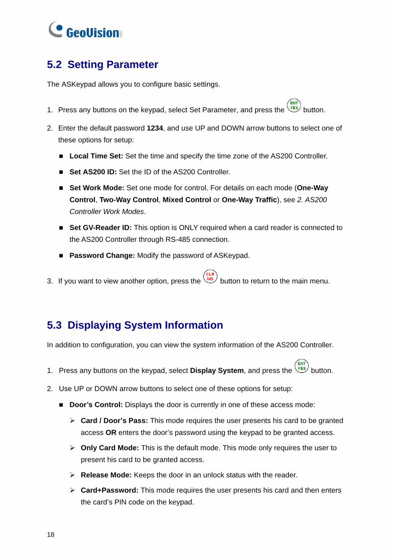
5.2 Setting Parameter
The ASKeypad allows you to configure basic settings.
1. Press any buttons on the keypad, select Set Parameter, and press the button.
2. Enter the default password 1234, and use UP and DOWN arrow buttons to select one of these options for setup:
Local Time Set: Set the time and specify the time zone of the AS200 Controller.
Set AS200 ID: Set the ID of the AS200 Controller.
Set Work Mode: Set one mode for control. For details on each mode (One-Way Control, Two-Way Control, Mixed Control or One-Way Traffic), see 2. AS200 Controller Work Modes.
Set GV-Reader ID: This option is ONLY required when a card reader is connected to the AS200 Controller through RS-485 connection.
Password Change: Modify the password of ASKeypad.
3. If you want to view another option, press the button to return to the main menu.
5.3 Displaying System Information
In addition to configuration, you can view the system information of the AS200 Controller.
1. Press any buttons on the keypad, select Display System, and press the button.
2. Use UP or DOWN arrow buttons to select one of these options for setup:
Door’s Control: Displays the door is currently in one of these access mode:
Card / Door’s Pass: This mode requires the user presents his card to be granted access OR enters the door’s password using the keypad to be granted access.
Only Card Mode: This is the default mode. This mode only requires the user to present his card to be granted access.
Release Mode: Keeps the door in an unlock status with the reader.
Card+Password: This mode requires the user presents his card and then enters the card’s PIN code on the keypad.

ASKeypad
19
5
Door’s Event: Displays what kind of event happened at the controlled door.
Memory’s State: Displays the memory usage of the unit.
Capacity: Shows the total number of the events that can be recorded. Note that the number limit of recorded events is 65536, and the system will rewrite the oldest events when the limit is reached. When the AS200 Controller is connected to ASServer, the event data will be uploaded to the server and the buffer of AS200 Controller will be cleared.
Used in: Displays the number of events that has been recorded.
ID & IP Address: Displays the ID to access AS200 Controller and the IP address of AS200 Controller.
Display Version: Displays the firmware version of AS200 Controller.
3. If you want to view another option, press the button to return to the main menu.

20

AS200E
21
6
6. AS200E The AS200E Controller, equipped with the Ethernet Module, can communicate with ASServer over the network. The following sections describe how to install the AS200E on the network and how to configure the AS200E over the network.
6.1 Installing AS200E on a Network
The AS200E Controller is able to support two network environments: Fixed IP and DHCP. Depending on your network, choose Fixed IP for a static IP address, or DHCP for a dynamic IP address such as those assigned by an ISP or other DHCP server.
6.1.1 Fixed IP Connection If your network environment supports a static IP address, the wiring is illustrated as below:
LAN or INTERNET
ASServer
Card Reader
Door
AS200E Controller

22
To assign the AS200E Controller to a fixed IP:
1. Open an Internet browser, and type the default IP address https://192.168.0.100. This dialog box appears.
Figure 1
2. In the User Name and Password fields, type default value admin and 1234 respectively. Click OK. This page appears.
Figure 2

AS200E
23
6
3. In the Machine Name field, name the connected AS200E Controller.
4. Click Disable. Type the static IP address information, including IP Address, Subnet Mask, Default Gateway and Domain Name Server.
5. Click Submit. When the connection is established, the Status field indicates Register Success.
6.1.2 DHCP Connection If your network environment is using the dynamic IP address from a DHCP server, please use one of the following DDNS servers to map a dynamic IP address to a static domain name or device name:
• For LAN connection, GV LocalDDNS Server is provided.
• For Internet connection, two DDNS servers are supported: GeoVision DDNS Server and Dynamic Network Services Inc. (DynDNS).
Note: If you like to use the domain name instead of IP address, you may use Domain Name Service as well. For details on domain name service, refer to DHCP Connection below.

24
6.1.2.1 Connection over LAN
The GV-developed “LocalDDNS Server” can map a device name to the varying IP address of your AS200E Controller, by which the ASServer can access the AS200E Controller by the device name.
The Local DDNS Server can be installed in either ASServer or a separate computer. The wiring of the LocalDDNS application is illustrated as below.
ASServer
Card Reader
Door
AS200E Controller
LAN(DDNS Server)
Note: The Local DDNS Server can be installed in (1) ASServer OR (2) a separate computer.
Installing LocalDDNS Server
To install the LocalDDNS Server in a computer, insert the Software CD. It will run automatically and a window appears. Select Install GeoVision V1.0 Access Control System, click GeoVision Dynamic DNS Service and follow the on-screen instructions.
After Installation, the program will be minimized to the system tray.

AS200E
25
6
Configuring AS200E on LAN
After running the LocalDDNS Server, configure the AS200E Controller on LAN:
1. Open an Internet browser, and type the default IP address https://192.168.0.100. The login dialog box (see Figure9) appears.
2. In the User Name and Password fields, type default value admin and 1234 respectively, Click OK. The Network Configuration page (see Figure 2) appears.
3. Click Enable, and select Send to Local DDNS.
4. In the Server IP field, type the IP address of the LocalDDNS Server.
5. In the Device Name field, keep the default setting or change it to match that of the ASServer.
Figure 3

26
6. Click Submit to send the information to the LocalDDNS Server. When the connection is established, the Status field indicates: Register Success.
Note: The default value of the device name is user. If more than one AS Contorller is connected to the ASServer, assign each device a different name.
6.1.2.2 Connection over Internet DDNS (Dynamic Domain Name System) provides another way of accessing the AS200E Controller when using a dynamic IP. DDNS assigns a domain name to the AS200E Controller, so the ASServer can always access the AS200E Controller by the domain name. To enable the DDNS function, you should first apply for a domain name from the DDNS service provider’s website. There are 2 providers listed in the AS200E Controller: GeoVision DDNS Server and DynDNS.org. To register at the GeoVision DDNS Server, see the following instructions. For details on DynDNS, please consult them at www.dyndns.org.
ASServer
Card Reader
Door
AS200E Controller
Internet(DDNS Server)
Note: Two DDNS servers are supported: (1) GV Dynamic DNS Server and (2) DynDNS.

AS200E
27
6
Registering a DDNS Domain Name To obtain a domain name from the GeoVision DDNS Server:
1. In the left menu pane, click Network Setting and click the GeoVision DDNS button (see Figure 2). Or open an Internet browser, and type the web address http://ns.dipmap.com/register.aspx . This page appears.
Figure 4
2. In the Username field, type a name. Username can be up to 16 characters with the choices of “a ~ z”, “0 ~9”, and “-”. Note that space or “-” cannot be used as the first character.
3. In the Password filed, type a password. Passwords are case-sensitive and must be at least 6 characters. Type the password again in the Re-type Password field for confirmation.
4. In the Word Verification section, type the characters or numbers shown in the box. For example, type i8UCY in the required field. Word Verification is not case-sensitive.
5. Click the Send button. When the registration is complete, this page appears.
Figure 5
Note: The registered name will be invalid when it is not used for one month.
28
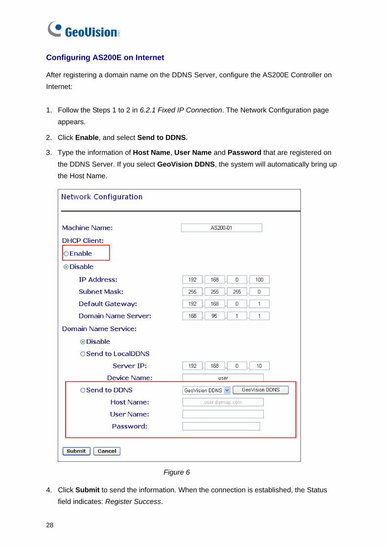
Configuring AS200E on Internet
After registering a domain name on the DDNS Server, configure the AS200E Controller on Internet:
1. Follow the Steps 1 to 2 in 6.2.1 Fixed IP Connection. The Network Configuration page appears.
2. Click Enable, and select Send to DDNS.
3. Type the information of Host Name, User Name and Password that are registered on the DDNS Server. If you select GeoVision DDNS, the system will automatically bring up the Host Name.
Figure 6
4. Click Submit to send the information. When the connection is established, the Status field indicates: Register Success.

AS200E
29
6
6.2 System Settings
You can execute certain system operations, change login password and view the version information of the firmware.
6.2.1 System Setup In the left menu pane, click Other Setting. This page appears.
Figure 7
3DES Code 1-3: Stands for Triple DES (Data Encryption Standard). Type up to three different keys for data encryption. The default 3DES Code1 is 12345678.
Device Port: Keeps the default value 4000. Or modify it to match that of the ASServer.
Mac Address: Indicates the MAC address of the network medium.
Firmware Version: Indicates the current firmware version of the AS200E Controller.
Reboot System: Performs a warm boot of the AS200E Controller. This operation will keep the current configuration.
Default Value: Resets all configuration parameters to their factory settings. This may take 5 seconds to complete.

30
6.2.2 Updating Firmware To update the firmware of the AS200E Controller:
1. In the left menu pane, click Firmware Update. This page appears.
Figure 8
2. Click the Browse… button to open the firmware file (*.bin)
3. Click the Upload button. This update procedure may take 60 seconds to complete.
4. When the Update is complete, a dialog box appears and asks you to reboot the system.
Figure 9
5. Click OK. The AS200E Controller starts the Reboot operation.
Note: It is required to reboot the AS200E Controller after updating the firmware. Without rebooting, the firmware update is not complete.

AS200E
31
6
6.2.3 Changing Login ID and Password To change the login ID and password: 1. In the left menu pane, click Security Setting.
2. On the Security Configuration page, modify the login name and password. The password is case sensitive and is limited to 4 characters with the choices of “a ~ z” and “0 ~ 9”.
Figure 10
6.2.4 Setting Controller ID and Work Mode The setting page allows you to modify the ID of AS200E Controller and set one work mode for control. For details on each mode (One-Way Control, Two-Way Control, Mixed Control or One-Way Traffic), see 2. AS200 Controller Work Modes.
Figure 11

32
Specifications
33
7
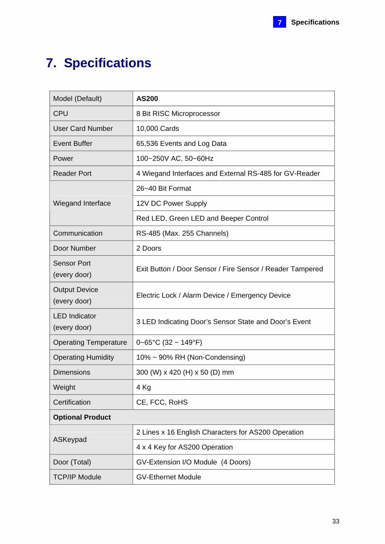
7. Specifications
Model (Default) AS200
CPU 8 Bit RISC Microprocessor
User Card Number 10,000 Cards
Event Buffer 65,536 Events and Log Data
Power 100~250V AC, 50~60Hz
Reader Port 4 Wiegand Interfaces and External RS-485 for GV-Reader
26~40 Bit Format
12V DC Power Supply Wiegand Interface
Red LED, Green LED and Beeper Control
Communication RS-485 (Max. 255 Channels)
Door Number 2 Doors
Sensor Port (every door)
Exit Button / Door Sensor / Fire Sensor / Reader Tampered
Output Device (every door)
Electric Lock / Alarm Device / Emergency Device
LED Indicator (every door)
3 LED Indicating Door’s Sensor State and Door’s Event
Operating Temperature 0~65°C (32 ~ 149°F)
Operating Humidity 10% ~ 90% RH (Non-Condensing)
Dimensions 300 (W) x 420 (H) x 50 (D) mm
Weight 4 Kg
Certification CE, FCC, RoHS
Optional Product
2 Lines x 16 English Characters for AS200 Operation ASKeypad
4 x 4 Key for AS200 Operation
Door (Total) GV-Extension I/O Module (4 Doors)
TCP/IP Module GV-Ethernet Module

34
8. Troubleshooting The card reader does not respond after being installed. If the card reader does not respond, it may be due to the power problem. Try these steps: 1. To verify the problem, remove the paper covered on the AS200 Controller module and
check if the power light of the card reader is ON.
2. If the card reader is connected over a long distance, use two additional resistors of 10K ohms to solve the problem. Insert one resistor between D0 and 12V and insert the other resistor between D1 and 12V.
12V
D0
D1GL
RL
BZ
GN
D
10K
10K
Power Light
Resistor
I cannot reset AS200 Controller to factory defaults.
1. Make sure you have plugged the ASKeypad to the AS200 Controller.
2. If the Ethernet module has been installed, make sure also to reset the Ethernet module.