Gurshaant Malik, Krishna Gupta, Raunak Dharani and K ... · FPGA based hybrid architecture for...
8
FPGA based hybrid architecture for parallelizing RRT Gurshaant Malik, Krishna Gupta, Raunak Dharani and K Madhava Krishna Abstract— Field Programmable Gate Arrays(FPGA) exceed the computing power of software based implementations by breaking the paradigm of sequential execution and accom- plishing more per clock cycle by enabling hardware level parallelization at an architectural level. Introducing parallel architectures for a computationally intensive algorithm like Rapidly Exploring Random Trees(RRT) will result in an explo- ration that is fast, dense and uniform. Through a cost function delineated in later sections, FPGA based combinatorial archi- tecture delivers superlative speed-up but consumes very high power while hierarchical architecture delivers relatively lower speed-up with acceptable power consumption levels. To combine the qualities of both, a hybrid architecture, that encompasses both combinatorial and hierarchical architecture, is designed. To determine the number of RRT nodes to be allotted to the combinatorial and hierarchical blocks of the hybrid architec- ture, a cost function, comprised of fundamentally inversely related speed-up and power parameters, is formulated. This maximization of cost function, with its associated constraints, is then mathematically solved using a modified branch and bound, that leads to optimal allocation of RRT modules to both blocks. It is observed that this hybrid architecture delivers the highest performance-per-watt out of the three architectures for differential, quad-copter and fixed wing kinematics. I. INTRODUCTION During the last decade and a half, as computer power has increased, sampling-based path planning algorithms, such as rapidly exploring random trees (RRT), have been shown to work well in practice and possess theoretical guarantees such as probabilistic completeness. A significant amount of research effort has gone into improving the performance of RRTs. From an architectural standpoint, recent research efforts have been directed towards parallelizing RRT [1] [2] [3] [4]. Out of these, distributed RRT [1] proffers the use of MPI for inter-module communication between multiple RRT modules to maintain data sanity, at the cost of inter- RRT scheduling. K-distributed [2] reduces this scheduling by lowring the amount of inter-RRT communication, at the cost of a less uniform exploration. However, FPGA based com- binatorial [3] and hierarchical [4] architectures, have already been shown to perform better than these implementations. FPGA enables delivery of tightly packed, energy efficient infrastructures adept in fast real time performance [5] [6] [7] [8]. Unlike a software effort in parallelization [1] [2], an FPGA allows gate level control of system architecture for parallelizing RRT. This allows the designer to tap the potential of hardware design, allowing control over minute details of arithmetic design, real time parallelization, pipe- lining of sequential processes. The hardware level flexibility afforded by an FPGA results in parallel RRT architectures that are not only fast, but also small and power efficient. FPGA based combinatorial and hierarchical architectures have already been shown to perform better than state of the art parallel RRT architectures like distributed [1] and K-distributed [2]. Fig. 1 summarises the respective speed-up and power consumption, as a function of N parallel RRTs for combinatorial and hierarchical architectures. As shown, the speed-up and power consumption of combinatorial is magni- tudes larger than hierarchical. Theoretically, an architecture with maximum speed-up and minimum power consumption is desired. To converge towards this theoretical ideality, as shown in Fig. 1, a flexible and malleable hybrid architecture that consists of M RRTs allotted to combinatorial and N -M RRTs allotted to hierarchical is proposed. The determination of M is mathematically calculated, with the calculations centered around maximization of a cost function, using a set of constraints explained in later sections. The subsequently designed hybrid architecture is then tested successfully for scalability across robotic kinematic complexity and geomet- ric complexity by deploying it for a differentially driven sys- tem, a quad-copter and fixed wing aircraft in geometrically constrained environments. Fig. 1. Overview : Hierarchical, Combinatorial and Hybrid architectures arXiv:1607.05704v1 [cs.RO] 19 Jul 2016
Transcript of Gurshaant Malik, Krishna Gupta, Raunak Dharani and K ... · FPGA based hybrid architecture for...

FPGA based hybrid architecture for parallelizing RRT
Gurshaant Malik, Krishna Gupta, Raunak Dharani and K Madhava Krishna
Abstract— Field Programmable Gate Arrays(FPGA) exceedthe computing power of software based implementations bybreaking the paradigm of sequential execution and accom-plishing more per clock cycle by enabling hardware levelparallelization at an architectural level. Introducing parallelarchitectures for a computationally intensive algorithm likeRapidly Exploring Random Trees(RRT) will result in an explo-ration that is fast, dense and uniform. Through a cost functiondelineated in later sections, FPGA based combinatorial archi-tecture delivers superlative speed-up but consumes very highpower while hierarchical architecture delivers relatively lowerspeed-up with acceptable power consumption levels. To combinethe qualities of both, a hybrid architecture, that encompassesboth combinatorial and hierarchical architecture, is designed.To determine the number of RRT nodes to be allotted to thecombinatorial and hierarchical blocks of the hybrid architec-ture, a cost function, comprised of fundamentally inverselyrelated speed-up and power parameters, is formulated. Thismaximization of cost function, with its associated constraints,is then mathematically solved using a modified branch andbound, that leads to optimal allocation of RRT modules to bothblocks. It is observed that this hybrid architecture delivers thehighest performance-per-watt out of the three architectures fordifferential, quad-copter and fixed wing kinematics.
I. INTRODUCTION
During the last decade and a half, as computer power hasincreased, sampling-based path planning algorithms, suchas rapidly exploring random trees (RRT), have been shownto work well in practice and possess theoretical guaranteessuch as probabilistic completeness. A significant amount ofresearch effort has gone into improving the performanceof RRTs. From an architectural standpoint, recent researchefforts have been directed towards parallelizing RRT [1] [2][3] [4]. Out of these, distributed RRT [1] proffers the useof MPI for inter-module communication between multipleRRT modules to maintain data sanity, at the cost of inter-RRT scheduling. K-distributed [2] reduces this scheduling bylowring the amount of inter-RRT communication, at the costof a less uniform exploration. However, FPGA based com-binatorial [3] and hierarchical [4] architectures, have alreadybeen shown to perform better than these implementations.FPGA enables delivery of tightly packed, energy efficientinfrastructures adept in fast real time performance [5] [6][7] [8]. Unlike a software effort in parallelization [1] [2],an FPGA allows gate level control of system architecturefor parallelizing RRT. This allows the designer to tap thepotential of hardware design, allowing control over minutedetails of arithmetic design, real time parallelization, pipe-lining of sequential processes. The hardware level flexibilityafforded by an FPGA results in parallel RRT architecturesthat are not only fast, but also small and power efficient.
FPGA based combinatorial and hierarchical architectureshave already been shown to perform better than state ofthe art parallel RRT architectures like distributed [1] andK-distributed [2]. Fig. 1 summarises the respective speed-upand power consumption, as a function of N parallel RRTs forcombinatorial and hierarchical architectures. As shown, thespeed-up and power consumption of combinatorial is magni-tudes larger than hierarchical. Theoretically, an architecturewith maximum speed-up and minimum power consumptionis desired. To converge towards this theoretical ideality, asshown in Fig. 1, a flexible and malleable hybrid architecturethat consists of M RRTs allotted to combinatorial and N−MRRTs allotted to hierarchical is proposed. The determinationof M is mathematically calculated, with the calculationscentered around maximization of a cost function, using a setof constraints explained in later sections. The subsequentlydesigned hybrid architecture is then tested successfully forscalability across robotic kinematic complexity and geomet-ric complexity by deploying it for a differentially driven sys-tem, a quad-copter and fixed wing aircraft in geometricallyconstrained environments.
Fig. 1. Overview : Hierarchical, Combinatorial and Hybrid architectures
arX
iv:1
607.
0570
4v1
[cs
.RO
] 1
9 Ju
l 201
6

II. CHALLENGES IN PARALLELIZING RRT
Since RRT involves randomized exploration of the map,ours and many proposed algorithms [1] [2] use the principleof exploratory decomposition [9] as their foundation. Inother words, each RRT produces its own output and throughdifferent write mechanisms, the outputs are integrated tobuild the explored map. Fig. 2 provides an overview of thisdesign philosophy.
Fig. 2. Schematic illustration of exploratory decomposition
In such a parallel RRT design, an important issue is todecide the write access mechanism that integrates the datafrom multiple RRTs and then updates the global exploredmap. There are 2 general philosophies : 1.) Distributed and2.) Shared. The distributed philosophy employs a scheme bywhich each RRT will have its own local explored map. Asa result, changes made by it to its local explored map willhave no effect on other RRT’s local explored maps. Hence,as shown in Fig. 3, we need a mediator system that updateseach RRT’s local explored map to changes made by otherRRTs. This will incur significant inter-RRT communicationtime in case of large scale parallelization.
Fig. 3. Schematic illustration of distributed philosophy
The shared design philosophy, shown in Fig. 4, allowsall the RRTs to have access to the same global exploredmap. Hence, there is virtually no inter-RRT communication.But, since all RRTs will have access to the same globalexplored map, large scale parallelization, without scheduling,can geometrically increase traffic on global address space,leading to data collisions.
Fig. 4. Schematic illustration of the Shared design philosophy
Conventional software implementation of parallel RRTs[1] [2] solve the problem of this contentious relationship be-tween scheduling and data integrity by using MPI, STAPLEframeworks. However hardware implementations, owing toRTL level optimizations being impossible on conventionalsoftware, have been shown to perform significantly betterthan their software counterparts in the case of parallel RRTs[3] [4]. As shown in Fig. 5, FPGA based hierarchicalarchitecture proposes a binary tree, that combines shared anddistributed memories, limits inter RRT scheduling to siblingRRTs only. Hence, it has a respectable speed and power costfunction.
Fig. 5. Hierarchical : Speed-up and Power plots. Best at 120% zoom
As shown in Fig. 6, combinatorial architecture eliminatesscheduling by introducing a multi-port shared memory andcombinatorial multiplexing, possible only as an FPGA im-plementation, taking care of all the possible 2N cases duringa write window for a N RRT system. Hence it has a veryhigh speed-up but also a very high power cost function.
Fig. 6. Combinatorial : Speed-up and Power plots. Best at 120% zoom
Ideally, a parallel RRT architecture should have a speed-upcapability similar to combinatorial and power consumptionlevels similar to hierarchical. The next section delineates onthis requirement with the proposed hybrid architecture.

III. PROPOSED HYBRID ARCHITECTURE
To enable intelligible understanding of the proposal, thissection is further divided into 3 subsections. 1.) HybridArchitecture’s hypothesis, 2.) Hybrid Architecture’s designand mathematical variables, 3.) Cost Function, to calculatethe hybrid architecture’s variables, strictly constrained by aset of intelligent, FPGA platform sensitive conditions.
A. Hypothesis
Owing to the probability reliant exploration of RRT,accurate prognosis of data arrival time is an ambiguous task.Hence N RRTs working in parallel can result in 2N possiblecases during a write window to the global road-map. In orderto theoretically rationalise the hypothesis behind the hybridarchitecture, it is important to characterize the architecture,speed-up and power consumption levels of the hierarchicaland combinatorial architectures, in chronological order.
In hierarchical, as shown in Fig. 7, the data stems from theRRT modules and flows through higher levels of hierarchyto reach the global map. P stands for POLL, F stands forFIFO. At the deepest level, P0 chronologically polls RRT0,RRT1. P1 polls RRT2, RRT3 and so on. Going up, F00 pollsP0, P1. F01 polls P2, P3 and so on. Going up a level, F10polls F00, F01 and F11 polls F02, F03. Finally, at the highestlevel, the global road-map is updated by F10 and F11. Atall levels, chronological polling for data by parent modulepreserves data integrity but the architecture is still weigheddown by the scheduling that prevails amongst child modulesof the parent modules. Eqs. 1 and 2 present the speed-up andpower consumption levels respectively for the hierarchicalarchitecture, extracted out of the data for speed-up and poweravailable with the authors, for N parallel RRT modules.
S(N) = 0.0019N2 + 0.41N + 2.8 (1)
P (N) = 0.17N + 1.8 (2)
Fig. 7. Hierarchical architecture
In combinatorial, as shown in Fig. 8, the first part of thearchitecture is a multi-port random access memory with theability to handle [0, N ] variable, asynchronous write and/orread transactions during a write and/or read window. Thesecond part of the architecture is a combinatorial circuit thatascertains the current case of the 2N cases during the writewindow and feeds the appropriate write control signals tothe memory. This allows each of the N RRTs to have access
to the write window with zero latency/scheduling since thiswrite access mechanism combinatorially accounts for all thepossible 2N cases. Eqs. 3 and 4 present the speed-up andpower consumption levels respectively for the combinatorialarchitecture, extracted out of the data for speed-up and poweravailable with the authors, for N parallel RRT modules.
S(N) = 0.021N3 + 5.7N + 3.3 (3)
P (N) = 1.6 ∗ 10−5 ∗N3 − 0.0048N2 + 0.79N + 1 (4)
Fig. 8. Combinatorial architecture
Comparing Eqs. 1 and 3, also plotted in Fig. 9, architec-turally, combinatorial aggressively out-throttles hierarchical.But on the other hand, comparing Eqs. 2 and 4, hierarchicalis of a much more clement nature in power consumption.It should be noted that speed-up directly controls the accel-erated capability of the system, that is, how fast a map isexplored. Mobile robots typically are constrained by a smallbattery. Hence, quantitatively, a maximal bound that is verysmall in magnitude needs to be placed on power consumptionlevels. Theoretically, it can be concluded with confidencethat an architecture that behaviorally is analogous to hier-archical in terms of power consumption and analogous tocombinatorial in terms of speed-up is ideal. Hence, a hybridarchitecture that combines these properties of hierarchicaland combinatorial is hypothesized.
Fig. 9. Speed-Up and Power : Combinatorial VS Hierarchical

B. Hybrid ArchitectureFig. 10 provides a top level architectural view of the
hybrid architecture for N parallel RRT modules. Consequentdelineation follows. The critical design philosophy instructsthe division of these N RRT modules into 2 parts : 1.)M RRT modules are aligned to follow the combinatorialarchitecture and 2.) Remaining N −M RRT modules arealigned to hierarchical architecture. Hence, by varying M ,the architecture can be made to cover the entire behavioralspectrum, with the extreme being hierarchical for M = 0and combinatorial for M = N . Eqs. 5 and 6 mathematicallyquantify this property.
SHybrid(M)→ [SHier(M = 0), SCombi(M = N)] (5)
PHybrid(M)→ [PHier(M = 0), PCombi(M = N)] (6)
TotalHier(M) = N −M (7)
TotalCombi(M) =M + 1 (8)
Fig. 10. Schematic illustration of hybrid architecture
As shown in Fig. 10, M RRT modules explore the mapin parallel via combinatorial architecture and the remainingN − M RRT modules explore the map in parallel viahierarchical architecture. These 2 exploration results are thencombined together to form the global explored road-mapvia combinatorial block(Hence, total M + 1 blocks). Eqs. 7and 8 describe the number of combinatorial and hierarchicalblocks respectively. For a given value of N , the entirebehavior of this architecture is administered by the variableM . The next subsection outlines the mathematical formulasand constraints critical to the deduction of the variable M .
C. Cost FunctionOwing to the mathematical complexity and volume in-
volved, for unabridged understanding of the concept, thissection is further divided into 4 subsections : 1.) The costfunction, 2.) Set of constraints to generate a singular, op-timized solution, 3.) The computation strategy to generatethe solution and 4.) Arbitration of the tagging of M RRTmodules out of the total N RRT modules.
1) Cost Function: Eqs. 1, 2, 3 and 4, clearly manifestthe irreconcilable nature of maximality and minimality be-tween speed-up and power consumption since both of themare proportional to the number of parallel RRT modules.That is, speed-up cannot be maximised in conjunction withminimised power consumption. Hence, instead of solitarymaximization of speed-up and minimization of power con-sumption, we aim to maximise the cost function given inEq. 9, with individual terms delineated in Eqs. 10 and 11,for a particular value of M . While adjudicating about theformulation of the cost function, it was observed that theform S/P was biased towards minimising power whereasS + 1/P was moderate in nature. As described in Eq. 8,it should be noted that for M combinatorial RRT modules,there exist M + 1 combinatorial blocks.
JHyb(M) = STotal(M) +1
PTotal(M)(9)
STotal(M) = SHier(N −M) + SCombi(M) (10)
PTotal(M) = PHier(N −M) + PCombi(M + 1) (11)
2) Set Of Constraints: The cost function is maximisedsubject to the following constraints :
• Naturally, M must be a positive integer
M > 0,∈ I (12)
• M must not exceed N
M ≤ N (13)
• Sensitive to robotic platform’s battery endurance ca-pability, the designer decides how much maximumpower(ω) the architecture can consume.
PHyb(M) ≤ ω (14)
3) Mathematical Solver: To solve for M , we aim tomaximise the cost function, as previously described in Eq.9. For this, Branch and Bound [10], a systematic solverfor optimized integer solutions, is used. Branch and boundhas the ability to accept non-linear optimization problemsas inputs, as is the case with the formulae. The genericalgorithm of branch and bound follows.

4) Tagging of M RRT modules: Post the calculation of M ,the next step assigns labels to each RRT as a combinatorial(M such RRTs) or hierarchical RRT ((N-M) such RRTs).This identification, as described in Eq. 15, is driven by theuser’s decision about the approximate average map area(α)each of the combinatorial M RRT modules should explore.As shown in Fig. 11, the map is divided into high resolutiongrids and the area is calculated, as described in Eqs. 16 and17, by summing the distance between that RRT module’sstarting node and each grid. It should be noted that the userhas the flexibility of intelligently [11] or randomly choosingthe starting nodes. For the current experimental setup, a valueof α was so chosen that the RRT nodes with the top M areaswere allotted to combinatorial architecture.
M∑i=1
AComb(i)
M≥ α (15)
AComb(i) =1∑grids
r=1 dr∗AMap (16)
dr = BFS.distance(gridr, nodei) (17)
Fig. 11. Calculation of distance for area estimation
IV. FPGA IMPLEMENTATION
The design platform, Zedboard, uses the Zynq-7000 SOC,with system parameters given in table below. For our design,the cartesian coordinates are represented as 32bit long, fixed-point, 2’s compliment binary strings where the 24 MSB rep-resent the integer part and the 8 LSB represent the fractionalpart. This representation provides an incremental resolutionof 0.00390625 in decimal format. The geometrical angle isrepresented as a 16bit long, fixed point, 2s compliment binarystring where the 3 MSB represent the integer part and the 13LSB represent the fractional part, affording an incrementalresolution of 0.00012207 radians.
System ParametersLUT 17,600 Total BRAM(Mb) 2.1Logic Cells 2800 DSP48E1 80CLB Flip Flops 35,200 Area(inch2) 6.5*5.9
Implementation breakdown, in a bottom to top manner, ofeach module shown in Fig. 12 follows.
Fig. 12. FPGA implementation : Hybrid architecture
A. RRT Module
As shown in Fig. 13, a pseudo-random number generatorgenerates a random state for the mobile robot in use. We usethe box [12] method to find the nearest node. Deployment ofDSP48E1 slices minimizes the time complexity of distancecomputation. CORDIC cores are used for computation oftrigonometric functions. DSP slices are then used for kine-matic extension.
Fig. 13. RRT implementation(Best viewed at 500% zoom)
B. POLL
As shown in Fig. 14, the POLL is implemented as asequential Finite State Machine(FSM). Isochronal cyclicpolling of child RRT modules germinated by rising edgeof clock leads to capture of data bus by one of the chil-dren, which then transfers its generated nodes via write-acknowledge mechanism.
Fig. 14. POLL implementation(Best viewed at 500% zoom)

C. FIFOAs Fig. 15 shows, we use built in FIFO resources to create
high performance, area optimized FIFO module. The First-Word-Fall-Through is chosen as the mode of operation forthe FIFO interface.
Fig. 15. FIFO implementation(Best viewed at 500% zoom)
D. Combinatorial CircuitFor N RRTs, the 2N possible cases and the corresponding
control signals of the multi-port memory are mapped tocascaded look up tables(LUTs). An N bit string, where eachbit corresponds to a RRT, is used as input. A 1 bit meansthat the corresponding RRT is requesting access and a 0 bitmeans otherwise. The outputs of this module are the controlsignals of the multi-port memory, as shown in Fig. 16.
Fig. 16. Schematic illustration of combinatorial circuit
E. Multi-port MemoryWith a global address space, the multi-port memory is
implemented as a heap of M distributed, single channelmemories, each of size (400F )/M KB, where F is thenumber of degrees of freedom of the robot and M is thenumber of RRTs. The read and write channels are designedasynchronous to enable independent read and write transac-tions. Auxiliary multiplexers on the read and write channelsapportion the global address space to local address spaces,as shown in Fig. 17.
Fig. 17. Schematic illustration of multi-port memory
V. RESULTS
The experimental setup was planned to qualitativelyquantify the architecture across 3 parameters : 1.)Efficiency/performance-per-watt, 2.) Scalability across map’sgeometric complexity and 3.) Scalability across kinematiccomplexity. Deployment across 1.) Differentially SteeredFirebird V(Actual Run), 2.) Quad-Copter (Simulation) and3.) Fixed Wing Aircraft (Simulation). Fig. 18 catalogues thetest kinematics(first row) and the corresponding 3 maps thearchitecture was tested on to quantify the above mentionedparameters.
Fig. 18. Left Column : Differential, Middle : FWA, Right : Quad-Copter
The test results quantify 3 parameters across kinematic andgeometric complexity : 1.) Speed-Up, 2.) Power consumptionand 3.) Performance-per-watt. As described in Eq. 18, speed-up refers to ratio of the time taken by 1 module to completea particular task, compared to the time taken by N parallelmodules, to complete the same task. Relative to the experi-mental setup, the equivalent task is to add 10, 000 explorednodes by N parallel RRT modules, initially seeded by amodified K-Means [11], to the map. The time is measured byan interrupt driven counter. The power statistics are extractedout of vector-less Vivado power analysis tool. Efficiency orperformance-per-watt, as defined in Eq. 19, is expected to bethe maximum for hybrid architecture.
S = T (1)/T (N) (18)
E = S/P (19)
(a) Map 1 : Efficiency VS No. of RRTs (b) Map 2 : Efficiency VS No. of RRTs (c) Map 3 : Efficiency VS No. of RRTs
(d) Map 1 : Efficiency VS No. of RRTs (e) Map 2 : Efficiency VS No. of RRTs (f) Map 3 : Efficiency VS No. of RRTs
(g) Map 1 : Efficiency VS No. of RRTs (h) Map 2 : Efficiency VS No. of RRTs (i) Map 3 : Efficiency VS No. of RRTs
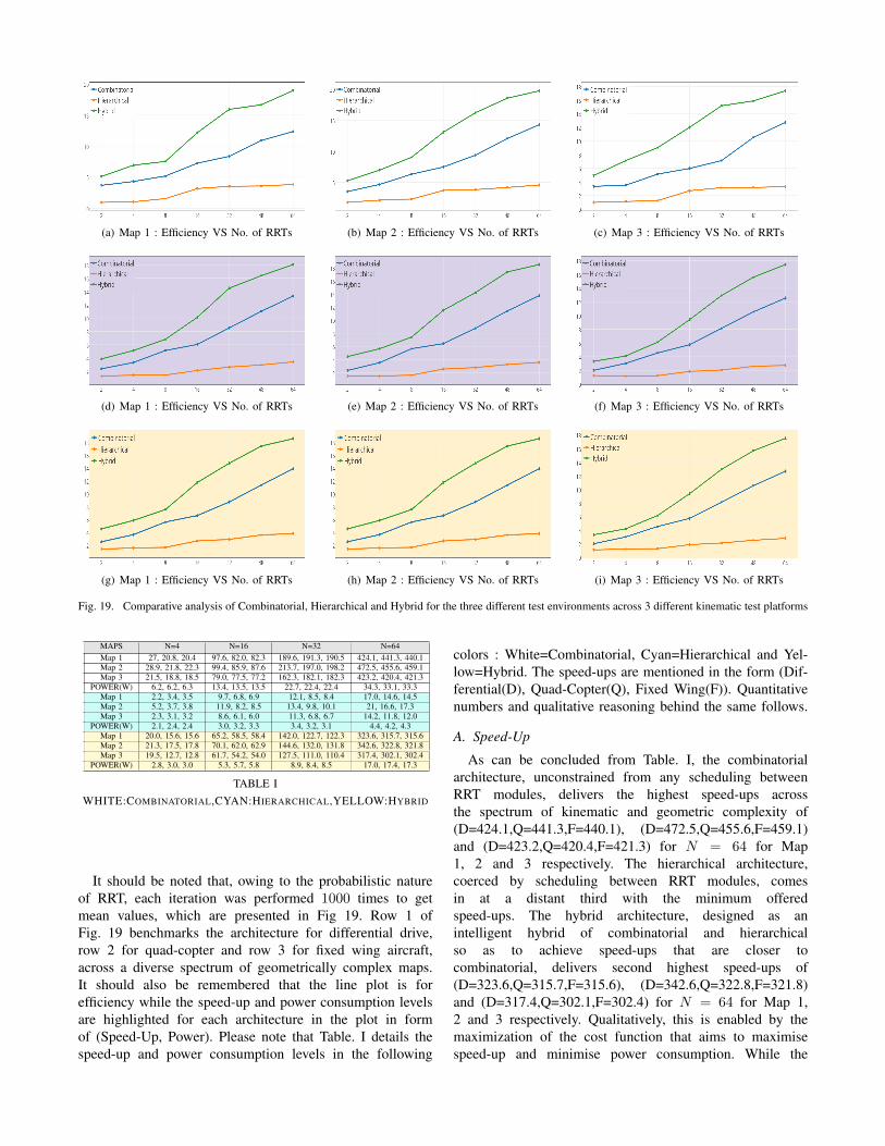
Fig. 19. Comparative analysis of Combinatorial, Hierarchical and Hybrid for the three different test environments across 3 different kinematic test platforms
MAPS N=4 N=16 N=32 N=64Map 1 27, 20.8, 20.4 97.6, 82.0, 82.3 189.6, 191.3, 190.5 424.1, 441.3, 440.1Map 2 28.9, 21.8, 22.3 99.4, 85.9, 87.6 213.7, 197.0, 198.2 472.5, 455.6, 459.1Map 3 21.5, 18.8, 18.5 79.0, 77.5, 77.2 162.3, 182.1, 182.3 423.2, 420.4, 421.3
POWER(W) 6.2, 6.2, 6.3 13.4, 13.5, 13.5 22.7, 22.4, 22.4 34.3, 33.1, 33.3Map 1 2.2, 3.4, 3.5 9.7, 6.8, 6.9 12.1, 8.5, 8.4 17.0, 14.6, 14.5Map 2 5.2, 3.7, 3.8 11.9, 8.2, 8.5 13.4, 9.8, 10.1 21, 16.6, 17.3Map 3 2.3, 3.1, 3.2 8.6, 6.1, 6.0 11.3, 6.8, 6.7 14.2, 11.8, 12.0
POWER(W) 2.1, 2.4, 2.4 3.0, 3.2, 3.3 3.4, 3.2, 3.1 4.4, 4.2, 4.3Map 1 20.0, 15.6, 15.6 65.2, 58.5, 58.4 142.0, 122.7, 122.3 323.6, 315.7, 315.6Map 2 21.3, 17.5, 17.8 70.1, 62.0, 62.9 144.6, 132.0, 131.8 342.6, 322.8, 321.8Map 3 19.5, 12.7, 12.8 61.7, 54.2, 54.0 127.5, 111.0, 110.4 317.4, 302.1, 302.4
POWER(W) 2.8, 3.0, 3.0 5.3, 5.7, 5.8 8.9, 8.4, 8.5 17.0, 17.4, 17.3
TABLE IWHITE:COMBINATORIAL,CYAN:HIERARCHICAL,YELLOW:HYBRID
It should be noted that, owing to the probabilistic natureof RRT, each iteration was performed 1000 times to getmean values, which are presented in Fig 19. Row 1 ofFig. 19 benchmarks the architecture for differential drive,row 2 for quad-copter and row 3 for fixed wing aircraft,across a diverse spectrum of geometrically complex maps.It should also be remembered that the line plot is forefficiency while the speed-up and power consumption levelsare highlighted for each architecture in the plot in formof (Speed-Up, Power). Please note that Table. I details thespeed-up and power consumption levels in the following
colors : White=Combinatorial, Cyan=Hierarchical and Yel-low=Hybrid. The speed-ups are mentioned in the form (Dif-ferential(D), Quad-Copter(Q), Fixed Wing(F)). Quantitativenumbers and qualitative reasoning behind the same follows.
A. Speed-Up
As can be concluded from Table. I, the combinatorialarchitecture, unconstrained from any scheduling betweenRRT modules, delivers the highest speed-ups acrossthe spectrum of kinematic and geometric complexity of(D=424.1,Q=441.3,F=440.1), (D=472.5,Q=455.6,F=459.1)and (D=423.2,Q=420.4,F=421.3) for N = 64 for Map1, 2 and 3 respectively. The hierarchical architecture,coerced by scheduling between RRT modules, comesin at a distant third with the minimum offeredspeed-ups. The hybrid architecture, designed as anintelligent hybrid of combinatorial and hierarchicalso as to achieve speed-ups that are closer tocombinatorial, delivers second highest speed-ups of(D=323.6,Q=315.7,F=315.6), (D=342.6,Q=322.8,F=321.8)and (D=317.4,Q=302.1,F=302.4) for N = 64 for Map 1,2 and 3 respectively. Qualitatively, this is enabled by themaximization of the cost function that aims to maximisespeed-up and minimise power consumption. While the

speed-up offered is definitely lower than combinatorial, itcan be confidently concluded that the hybrid architecturedelivers on the hypothesis of near combinatorial emulation.
B. Power Consumption
It should be remembered that the static, vector-less poweranalysis is independent of kinematic and geometric complex-ity. Analysis of power consumption data, as given in Table.I in fourth row of each of the colour segments, reveals thathierarchical, owing to the relatively pliant architecture, con-sumes the least power levels of (D=4.4W,Q=4.2W,F=4.3W)for N = 64. Combinatorial, owing to its expansive com-binatorial blocks, is the most power hungry among thethree. Hybrid, on the other hand, tries to closely borderhierarchical, expending (D=17.0W,Q=17.4W,F=17.3W) forN = 64. Qualitative justification behind this behaviour isexplicated by the maximization of the cost function that aimsto minimise power consumption.
C. Efficiency
To appreciate the benchmarking primacy hybrid archi-tecture enables over other architectures, it is important tounderstand that the architecture was designed to maximisespeed-up and minimise power consumption concurrently,despite them being antithetical to each other by nature. Themaximization of the designed cost function should enablethe hybrid architecture to be the most judicious in efficiencyor performance-per-watt. This hypothesis is proven true inFig. 19. As quantized in previous subsections, combinatorialarchitecture delivers the maximum performance and hierar-chical consumes the least amount of power. But, the hybridtends to closely track the leader in both departments, asalready seen. This loose behavioral emulation by the hybridarchitecture allows the hybrid architecture to out-throttle bothcombinatorial and hierarchical in terms of performance-per-watt/efficiency. This out-throttling is observed across thevaried spectrum of both geometric as well as kinematiccomplexities. Hybrid architecture is the most efficient of the3 architectures with numbers of (D=18.9,Q=18.0,F=18.5),(D=19.7,Q=18.5,F=18.5) and (D=20.4,Q=17,4,F=17.5) forN = 64 for Map 1, 2 and 3 respectively. This is true acrossthe complete range of N .
Fig. 20. Demo of hybrid architecture for differential and quad-copter
For perceptible understanding, sample runs of differen-tial drive and quad-copter is presented in Fig. 20. Pinkcorresponds to exploration by hierarchical and green by
combinatorial respectively. Video of demo is also available.This benchmarking exercise, performed across varied kine-matics and maps, quantitatively proves the 3 qualities ofhybrid architecture : 1.) Maximum efficiency/performance-per-watt, 2.) Scalable across map’s geometric complexity and3.) Kinematic complexity.
VI. CONCLUSION
This paper proffered the hybrid architecture that, apartfrom benefiting from the inherent parallel abilities of theFPGA, is able to deliver the maximum performance-per-wattamongst state of the art hardware architectures. Quantitativebenchmarking of this architecture across different kinematicsystems, from land based kinematics to complex aerial kine-matics, on maps with tight geometric constraints exhibitedthe architecture’s scalability across kinematic and geometriccomplexity.
As part of our future work, the authors would like to studythe scalability of this architecture for non-still, dynamicallychanging maps with moving obstacles. The authors wouldalso like to extend the optimization methods that enablesgreater combinatorial speed-up and hierarchical power emu-lation respectively.
REFERENCES
[1] Didier Devaurs, Thierry Simeon, and Juan Cortes. Parallelizing rrton distributed-memory architectures. In Proc. IEEE ICRA’11, pagespp–2261, 2011.
[2] Nick Stradford, Sam Ade Jacobs, and Nancy M Amato. Scalableparallel rrt method for motion planning.
[3] Gurshaant Singh Malik, Krishna Gupta, K Madhava Krishna, andShubhajit Roy Chowdhury. Fpga based combinatorial architecturefor parallelizing rrt. In Mobile Robots (ECMR), 2015 EuropeanConference on, pages 1–6. IEEE, 2015.
[4] Gurshaant Singh Malik, Krishna Gupta, K Madhava Krishna, andShubhajit Roy Chowdhury. Fpga based hierarchical architecture forparallelizing rrt. In Proceedings of the 2015 Conference on AdvancesIn Robotics, page 12. ACM, 2015.
[5] Jan Fischer, Alexander Ruppel, Florian Weisshardt, and AlexanderVerl. A rotation invariant feature descriptor o-daisy and its fpgaimplementation. In Intelligent Robots and Systems (IROS), 2011IEEE/RSJ International Conference on, pages 2365–2370. IEEE, 2011.
[6] Jan Svab, Tomas Krajnik, Jan Faigl, and Libor Preucil. Fpga basedspeeded up robust features. In Technologies for Practical RobotApplications, 2009. TePRA 2009. IEEE International Conference on,pages 35–41. IEEE, 2009.
[7] Jason Oberg, Ken Eguro, Ray Bittner, and Alessandro Forin. Randomdecision tree body part recognition using fpgas. In Field Pro-grammable Logic and Applications (FPL), 2012 22nd InternationalConference on, pages 330–337. IEEE, 2012.
[8] Roopak Dubey, Neeraj Pradhan, K Madhava Krishna, and Shubha-jit Roy Chowdhury. Field programmable gate array (fpga) basedcollision avoidance using acceleration velocity obstacles. In Roboticsand Biomimetics (ROBIO), 2012 IEEE International Conference on,pages 2333–2338. IEEE, 2012.
[9] Vipin Kumar, Ananth Grama, Anshul Gupta, and George Karypis.Introduction to parallel computing: design and analysis of algorithms.Benjamin/Cummings Publishing Company Redwood City, CA, 1994.
[10] Eugene L Lawler and David E Wood. Branch-and-bound methods: Asurvey. Operations research, 14(4):699–719, 1966.
[11] K. Madhava Krishna. K-Means derived strategized placement ofstarting points for parallel RRTs. In IIIT Hyderabad Publications,page 145. IIIT, Hyderabad, 2016.
[12] Mikael Svenstrup, Thomas Bak, and Hans Jørgen Andersen. Minimis-ing computational complexity of the rrt algorithm a practical approach.In Robotics and Automation (ICRA), 2011 IEEE International Con-ference on, pages 5602–5607. IEEE, 2011.


![COCA COLA by Dharani Kumar 306[1]](https://static.fdocuments.us/doc/165x107/577d1de91a28ab4e1e8d41bf/coca-cola-by-dharani-kumar-3061.jpg)