GUN MOUNTS - Reliable Security Information · Gun Carriage—The gun carriage is also called the...
24
CHAPTER 6 GUN MOUNTS The guns aboard modern naval vessels, though complex in detail, are made up of basic components that vary little from one gun to the next. In this chapter we describe these common components and how they function. The remainder of the chapter is dedicated to describing the operation of the gun systems in the fleet today, including misfire procedures. GUN COMPONENTS LEARNING OBJECTIVES: Describe common gun system components and discuss the purpose of each component. Every gun system includes equipment used for gun positioning, loading, and firing. Although loading equipment varies in design from gun to gun, its purpose remains the same-to load a complete round in the gun chamber for firing. The greatest similarities between the guns are the positioning and firing components. We will describe these components first, followed by a discussion of the various gun systems in use today. As we discuss each gun system, we will describe the major components and how they work together to load and shoot a complete round of ammunition. Before we begin, let’s examine three terms that are very basic to this subject—ordnance, gun, and gun mount. As terminology is basic to a thorough understanding of gunnery, other terms have been highlighted throughout this discussion to attract your attention. ORDNANCE—Ordnance is the term covering all weapons, weapons system components, and support equipment (guns, ammunition, missiles, launchers, bombs, rockets, mines, torpedoes, fire control, and so forth). GUN—A gun is a tube, closed at one end, from which a projectile is ejected at high speed by the gases produced from rapidly burning propellants. GUN MOUNT—A gun mount consists of all the machinery used to position, load, and fire a gun. POSITIONING EQUIPMENT Positioning equipment includes all the machinery used to support and move the gun tube to the desired train (horizontal) and elevation (vertical) angle. This includes the stand, the base ring, the trunnion, the gun carriage, and the slide, as shown in figure 6-1. It also includes the gun train and elevation power drives. Stand-The stand is a steel ring bolted to the deck that serves as a foundation and rotating surface for movement in train. The stand contains both the train bearings and the training circle. The training circle is a stationary internal gear that the train drive pinion “walks around’ to move the gun in train. Base Ring-The base ring is also called the lower carriage. It is the rotating platform, supported by the stand, that supports the upper carriage. Figure 6-1.—Gun-positioning equipment. 6-1
Transcript of GUN MOUNTS - Reliable Security Information · Gun Carriage—The gun carriage is also called the...

CHAPTER 6
GUN MOUNTS
The guns aboard modern naval vessels, thoughcomplex in detail, are made up of basic components thatvary little from one gun to the next. In this chapter wedescribe these common components and how theyfunction. The remainder of the chapter is dedicated todescribing the operation of the gun systems in the fleettoday, including misfire procedures.
GUN COMPONENTS
LEARNING OBJECTIVES: Describe commongun system components and discuss thepurpose of each component.
Every gun system includes equipment used for gunpositioning, loading, and firing. Although loadingequipment varies in design from gun to gun, its purposeremains the same-to load a complete round in the gunchamber for firing. The greatest similarities betweenthe guns are the positioning and firing components. Wewill describe these components first, followed by adiscussion of the various gun systems in use today. Aswe discuss each gun system, we will describe the majorcomponents and how they work together to load andshoot a complete round of ammunition.
Before we begin, let’s examine three terms that arevery basic to this subject—ordnance, gun, and gunmount. As terminology is basic to a thoroughunderstanding of gunnery, other terms have beenhighlighted throughout this discussion to attract yourattention.
ORDNANCE—Ordnance is the term covering allweapons, weapons system components, and supportequipment (guns, ammunition, missiles, launchers,bombs, rockets, mines, torpedoes, fire control, and soforth).
GUN—A gun is a tube, closed at one end, fromwhich a projectile is ejected at high speed by the gasesproduced from rapidly burning propellants.
GUN MOUNT—A gun mount consists of all themachinery used to position, load, and fire a gun.
POSITIONING EQUIPMENT
Positioning equipment includes all the machineryused to support and move the gun tube to the desiredtrain (horizontal) and elevation (vertical) angle. Thisincludes the stand, the base ring, the trunnion, the guncarriage, and the slide, as shown in figure 6-1. It alsoincludes the gun train and elevation power drives.
Stand-The stand is a steel ring bolted to the deckthat serves as a foundation and rotating surface formovement in train. The stand contains both the trainbearings and the training circle. The training circle is astationary internal gear that the train drive pinion“walks around’ to move the gun in train.
Base Ring-The base ring is also called the lowercarriage. It is the rotating platform, supported by thestand, that supports the upper carriage.
Figure 6-1.—Gun-positioning equipment.
6-1

Gun Carriage—The gun carriage is also called theupper carriage. It is a massive pair of brackets that holdsthe trunnion bearings. The trunnion bearings supportthe trunnions, which are part of the slide, togetherforming the elevation pivot point.
Slide—The slide is a rectangular weldment that- supports all the elevating parts of the gun.
THE 5"/54 MK 45 MOD 0 GUN MOUNTPOWER DRIVE
The power drives for the 5"/54 Mk 45 Mod 0 gunmount consists of the train and elevation power drives.The train power drive responds to one set of ordersignals to rotate the carriage, while the elevation powerdrive responds to another set of order signals.Activation of the power drives occurs as follows:
1. The elevation and train motors are started. Theelevation motor is started first because it furnishes servoand supercharge fluid to both the elevation and trainpower drives.
2. The power-off brakes release when a mode ofoperation is selected.
3. After being assigned to a fire control system byweapons control, the mount trains and elevates inresponse to a remote signal.
General Description
The power drives for the 5"/54 Mk 45 gun mountare physically smaller than those used on the Mk42 gun mounts because the Mk 45 gun mount is lighterin weight. Other than size, the main difference involvesthe use of only one gear pump and one auxiliary relief
Figure 6-2.-Elevation system power drive.
6-2
valve block to provide the fluid pressure for both thetrain and elevation power drive servo and superchargerequirements. Because the train and elevation powerdrives on this mount operate in a similar manner, onlythe elevation power drive is presented. Figure 6-2shows the arrangement of the principal elevation powerdrive components.
Electric Motor (5"/54)
A 15-horsepower constant-speed electric motordrives the A-end of the cab unit. The train and elevationpower drives are independent with their own motors.The motors are supplied with 440-volt, 60-Hz powerfrom the EP1 panel.
Hydraulic Transmission (CABUNIT)
This CAB unit (fig. 6-3) consists mainly of anA-end, a valve plate, and a B-end. Here, a briefdescription of how they operate is presented.
A-END.— The A-end is coupled to, and driven by,the elevation electric motor. Controlled hydraulic fluidfrom the receiver-regulator, acting on stroking pistonsin the A-end, controls the volume and direction of fluidthat the A-end pumps to the B-end. The A-end output,therefore, controls the speed and direction of rotation ofthe B-end output shaft.
Figure 6-3.—Elevation CAB unit (cutaway view),
6-3
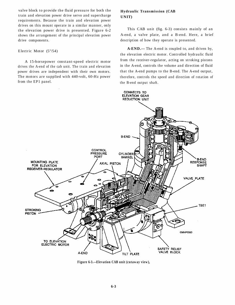
The cylinder barrel in the A-end (fig. 6-4) containsnine pistons located axially around the drive shaft. Thepistons reciprocate (move back and forth) within thecylinder bores, drawing fluid in during 180-degreerotation of the A-end and discharging fluid during theother 180-degree rotation. The volume of fluid pumpeddepends on the length of piston travel in the cylinderbore, which is determined by the angle of the variabletilt plate. Two stroking pistons, one on each side of thetilt plate, control the tilt plate angle.
VALVE PLATE.— The stationary valve plate,located between the A-end and B-end, has twocrescent-shaped ports. The valve plate keeps the fluidbeing drawn into the A-end separate from the fluidbeing discharged under pressure to the B-end.
B-END.— The B-end, with its fixed-position tiltplate, operates in a reverse manner from the A-end,converting fluid flow into rotary motion. When fluidoutput from the A-end piston is applied to the B-endpiston, the resultant thrust of the ball-end connectingrod against the inclined socket ring causes the socketring to rotate. A universal joint connects the socket ringto the B-end output shaft so that both the output shaftand the cylinder barrel rotate with the socket ring (fig.6-4). The cylinder barrel rotates against the twocrescent-shaped ports in the valve plate. One portsupplies A-end fluid to the axial pistons for a thruststroke and the other port receives displaced fluid fromthe pistons on the retract stroke. During continuousrotation of the B-end, hydraulic fluid from the A-end isapplied to the piston for the thrust stroke. As the
cylinder bore moves past the land separating the twoports, fluid empties into the discharge port as the pistonmoves in the retract stroke. The discharge port for theB-end, which is replenished with supercharge fluid,connects to the intake port for the A-end. This actionkeeps hydraulic fluid in the CAB unit circulating withina closed loop with only supercharge fluid replenishingfluid lost through slippage.
Safety Relief Valve
The elevation safety relief valve (fig. 6-5, view A)is a compound relief valve, consisting of a pilot valve(UVE67), main relief valve (UVE68), and four checkvalves (UVE69, UVE70, UVE71, and UVE72). Thereare two springs in the valve block that hold UVE67 andUVE68 seated until an excessive pressure conditionoccurs. There are two control orifices in UVE68 thatprevent pressure buildup in the CAB unit during normaloperation.
The safety relief valve has two functions:
1. It limits hydraulic pressure buildup in thehigh-pressure output line of the A-end. (It operates inconjunction with the pressure cutout switch SIE2A.)
2. It prevents pump cavitation by portingsupercharge fluid to the low-pressure return line of theA-end (compensating for fluid lost through slippageand leakage).
The direction of the A-end stroke determines whichchamber of the valve plate ports A-end output (high
Figure 6-4.—CAB unit (mechanical schematic).
6-4

Figure 6-5.—Safety relief valve operation.
6-5

pressure) fluid and which ports return (low pressure)fluid. The operation of the main relief valve, however,is independent of the direction of stroke. Figure 6-5,view A, shows the valve plate feeding A-end output tochamber A and return fluid to chamber B of the mainrelief valve. The valve functions in the same mannerwhen the fluid in chambers A and B are reversed.
Check valves UVE71 and UVE72 control the flowof supercharge fluid to the CAB unit valve plate. Checkvalves UVE69 and UVE70 allow the flow of A-endoutput to UVE67 while preventing its flow into thereturn passages. During normal operation, A-enddischarge fluid pressure holds one check valve open andthe other closed. With A-end discharge fluid inchamber A´, UVE70 opens a passage leading to the pilotvalve UVE67 in the safety relief valve block, to the pilotvalve UVE16 in the auxiliary relief valve block, and tothe reverse side of UVE69. When the discharge fluidpressure is in chamber B´, UVE69 opens chamber B´ toUVE67, to UVE16, and to the reverse side of UVE70.
The plunger of the main relief valve (UVE68) hasfour faces of identical effective areas. These areas arein chambers A, A´, B, and B´. It also has identicalorifices (UOE9 and UOE10) that restrict the flow offluid from chambers A to A´ and from B to B´. Whenno fluid is flowing from the lower chambers to the upperchambers, the hydraulic pressure in all four chambersis equal. When discharge fluid pressure in A and A´are equalized and supercharge fluid pressure in B andB´ are equalized, the only effective force is the initiallycompressed mainspring that holds the plunger seated.
When either UVE67 or UVE16 opens to the tank,it also opens chambers A´ and B´ to the tank. Any fluidflow through UVE67 or UVE16 must come from thevalve plate through the two orifices and UVE70 andUVE69. The fluid pressure in the upper chambersdrops below that in the lower chambers because of theorifices. When this occurs, the fluid pressureovercomes the force of the mainspring and the UVE68plunger unseats. Now, with UVE68 unseated, A-enddischarge fluid in chamber A bypasses to chamber Band into the return (low pressure) passage of the valveplate.
During normal operation the conditions affectingthe safety relief valve are as follows:
1. The A-end is on stroke.
2. Valve UVE16 in the auxiliary relief valve blockis blocking discharge fluid.
3. The power-off brake is released.
Under these conditions, UVE68 is in hydraulicbalance and its plunger is seated. Any variation in theload on the CAB unit varies the discharge pressure inthe valve plate. This variation acts on the top ofUVE67.
During normal operations, however, the fluidpressures do not exceed the preload of the UVE67spring. Accordingly, UVE67 never bypasses fluid tothe tank. With no line open to the tank, the main reliefvalve cannot unseat.
During excessive pressure operation (fig. 6-5, viewB), the conditions affecting the safety relief valve are asfollows:
1. The A-end is on stroke.
2. Either the gun barrel elevates or depresses intoa physical obstruction or the brake sets as the result ofa power failure. (The physical obstruction could besomething on deck or it could be the elevation ordepression buffer.)
The pressure cutout switch (SIE2A) in the tank lineof UVE67 shuts down the electric motor to protect thevalve plate against high temperatures developed duringprolonged bypassing (more that 0.9 second). Thepreload of the UVE67 spring determines the hydraulicpressure required at the top of UVE67 to unseat itsplunger and, in turn, to bypass discharge fluid to thetank through the slot in the plunger. Thus the two valvesthat determine when the main relief valve unseats areUVE67 and UVE16.
When the gun elevates or depresses into a physicalobstruction, pressure in the discharge passage of thevalve plate rises beyond the bypass limit of the safetyrelief valve. This abnormally high pressure offsets thepreload of the UVE67 spring and shifts the UVE67plunger downward to bring slot S and counterbore Pinto line-to-line orientation. Further increase inpressure on the top of UVE67 shifts the plunger fartherdown to permit a proportional flow of discharge fluidto the tank through counterbore P and slot S.
When the resulting flow causes the pressure in thelower chambers of UVE68 to offset the force of themainspring, the UVE68 plunger unseats. Thus thesafety relief valve keeps the discharge pressure in theCAB unit within the bypass limit.
Servo and Supercharge Supply System
The servo and supercharge supply system consistsof a servo and supercharge pump, an auxiliary reliefvalve block, a servo accumulator, a charging valve, and
6-6

a pair of fluid filters. This system shares the main tankand the header tank with the upper accumulator system.
SERVO AND SUPERCHARGE PUMP.— Theservo and supercharge pump is mounted on the aft endof the right trunnion support and is driven by theelevation electric motor. This dual output gear pumpsupplies servo fluid to control both CAB units (train andelevation) and also the supercharge fluid to replenishthe CAB unit slippage.
AUXILIARY RELIEF VALVE BLOCK.— Theauxiliary relief valve block (fig. 6-6) is mounted in themiddle of the right trunnion support. Its purpose is tolimit supercharge fluid pressure to 150 psi, limit servofluid pressure to 450 psi, control the operation of thepower-off brake, indicate by means of switches theavailability of supercharge and servo fluid pressures,
and provide a flow of fluid to cool the elevation andtrain the CAB units.
When the elevation electric motor is started, filteredsupercharge fluid enters the valve block through checkvalve UV77 and is ported to the center of superchargepressure relief valve UV59. From UV59, it ports to thetrain and elevation safety relief valves to replenish thetransmission lines. As supercharge fluid builds up to itsnormal operating pressure of 150 psi, it forces UV59downward against its spring and, through orifice UO4,forces supercharge pressure switch piston UC5 upwardagainst its spring. When supercharge fluid reaches 150psi, UC5 activates switch SIY3 indicating thatsupercharge fluid pressure is normal and, at the sametime, UV59 moves down and opens a port that bypassespart of the supercharge fluid to the elevation CAB unit.
Figure 6-6.—AuxiIiary relief valve block (elevation motor started).
6-7

Thus UV59 maintains supercharge fluid pressure at 150psi and bypasses the surplus fluid to circulate through,and cool, the elevation CAB unit.
Servo pressure relief valve UV58 functions in thesame manner as UV59 to limit servo fluid pressure to450 psi. Orifice UO3, piston UC6, and switch SIY4function in the same manner as do orifice UO4, pressureswitch piston UC5, and switch SIY3.
Servo fluid is ported to both train and elevationpower-off brake release plungers UVT18 and UVE18,to the solenoid-operated pilot valves UVE86 andUVT86, and to the servo accumulator. Surplus servopump output is also ported by UV58 to circulate throughand cool the train CAB unit when servo fluid pressurereaches 450 psi.
Solenoids LHT1 and LHE1, located on top of theauxiliary relief valve block, set or release the power-offbrakes and activate the safety relief valves. WhenLHE1 energizes (fig. 6-7), UVE86 shifts to the left,porting servo fluid to the bottom of UVE18. As UVE18moves upward against spring tension, its lower landcloses a port to the tank and its upper land opens a servo
fluid line to power-off brake release piston UCE1. Atthe same time, the center land of UVE18 opens anotherservo fluid line to the left end of pilot valve UVE16,shilling it to the right and blocking the A-end outputfrom the elevation safety relief valve. With the A-endoutput blocked by UVE16, the safety relief valve seats,allowing the A-end output to build up pressure to theB-end.
When the elevation power drive is stopped, LHE1de-energizes and shifts UVE86 to its NEUTRALposition, porting the fluid on the bottom of UVE18 tothe tank. This closes the servo fluid line and portsUCE1 to the tank, setting the power-off brake. Pilotvalve UVE16 then shifts to the left because the pressureon its left end is ported to the tank and is spring loaded.This allows the safety relief valve to open and portA-end output to the tank.
SERVO ACCUMULATOR.— The servoaccumulator (fig. 6-8) maintains a reserve of servopressure to meet peak demands for both the train andelevation power drives. Servo pressure enters theaccumulator through a spring-loaded check valve,
Figure 6-7.—Auxiliary relief valve block (power-off brake released).
6-8

FIRING EQUIPMENT(GENERAL)
Figure 6-8.—Servo accumulator (schematic diagram),
UV84. Valve UV84 prevents accumulator pressurefrom feeding back through the pump during shutdown.Fluid then ports to the accumulator flask and to thereceiver-regulator of each power drive. The fluidreserve in the flask is held under pressure by thenitrogen charged bladder,
THE MK 75 76MM POSITIONINGEQUIPMENT
The Mk 75 uses two 3-kW low-inertia dc motorsand reduction gearing for train and a single 4.5-kW dcmotor and reduction gearing for elevation. This systemwas discussed in detail in chapter 5.
LEARNING OBJECTIVE: Describe the firingequipment common to all naval gun mounts.
The firing equipment includes all the componentsnecessary to allow the gun to fire safely, absorb theshock of recoil, and reposition for further firing. Thisincludes the housing, the breechblock, the recoilsystem, the counterrecoil system, the firing circuits, andthe firing cutouts.
Housing—The housing is a large steel casement inwhich the barrel and breechblock are fitted. Thehousing moves in recoil inside the slide.
Breechblock—The breechblock seals the breechend of the barrel. Breechblocks are of two differenttypes—sliding wedge or interrupted thread. Theslidlng wedge consists of a machined steel plug thatslides in a grooved way in the housing to cover thebreech opening. The grooves are slanted so that thebreechblock moves forward as it covers the back of thecasing, wedging it in place. The interrupted threadbreech plug closes similar to the way a bayonet lugcamera lens is installed. The lugs on the plug are cut toallow it to be inserted into the grooves cut in thethreaded breech. Once inserted, the plug is turned 120”and locked in place. The Mk 45 and Mk 75 use thesliding wedge breechblock. The sliding wedgebreechblock is shown in figure 6-9.
Figure 6-9.—The sliding wedge breechblock.
6-9

Figure 6-10.—Recoil and counterrecoil systems.
Recoil System—Normally, a recoil system (fig.6-10) consists of two stationary pistons attached to theslide, set in a liquid-filled cylinder in the housing. Asthe housing moves rearward in recoil, the trapped liquidis forced around the piston head through meteredorifices, slowing the movement of the housing.
Counterrecoil System—A counterrecoil systemconsists of a piston (or pistons) set in a pressurizedcylinder. As the gun recoils, the piston protrudesfurther into the cylinder. After the force of recoil isspent, the nitrogen pressure, acting against the piston,pushes the housing back into battery (the full forwardposition). The piston may be attached to the slide or setin a chamber mounted to the inside of the slide. Figure
6-11 shows the configuration used on the 5"/54 Mk 45gun system. Nitrogen pressure holds the free-floatingpistons against the back of the housing, which forcesthem into the stationary chamber during recoil.
Since the nitrogen pressure in the counterrecoilsystem is the only thing holding the gun in battery, allguns are equipped with a safety link. The safety linkphysically attaches the housing to the slide to prevent itfrom moving if system pressure is lost. The safety linkis disconnected before firing.
Firing Circuits-Basically, a firing circuit suppliesfiring voltage to the propelling charge primer. Thissounds simple, but the application can be quitecomplicated. Certain conditions must exist before
Figure 6-11.—5"/54 Mk 45 recoil and counterrecoil systems.
6-10

firing to ensure a safe evolution. Making sure the gunis pointed in a safe direction, all the loading equipmentis in the FIRE position (out of the way of recoiling parts)and the breechblock is all the way closed are just a fewof the obvious things that must be correct before firing.A typical electronic firing circuit includes interlockinputs that serve to monitor these and many otherconditions, allowing firing voltage to pass only after allsafety conditions have been satisfied.
Firing Cutouts—A firing cutout mechanisminterrupts firing when the gun is pointed at or nearpermanent ship’s structure. A firing cutout is amechanical device that monitors the gun position.Figure 6-12 shows a firing cutout mechanism. Noticethe inputs from the system. The gun train position input
rotates the cam, while the elevation input positions thefollower. While the cam follower is on a low area ofthe cam, the firing circuit is closed or enabled. As thegun trains and elevates and the follower rides upon araised portion of the cam, the firing circuit is opened.
PREFIRE REQUIREMENTS(GENERAL)
LEARNING OBJECTIVE: Describe generalprefire requirements for naval gun mounts.
Before firing, each of these systems must beinspected and tested. Gun power drives and the loading
Figure 6-12.—Firing cutout mechanism, response gearing, and cam.
6-11

system have their hydraulic fluid levels checked, are GUN SYSTEMS
inspected for gear adrift, and then are test-operated.Fluid levels in the recoil and counterrecoil systems arechecked and firing circuits and firing cutouts are tested. LEARNING OBJECTIVE: Discuss the gunThe detailed procedure for performing prefire checks is crew positions and their responsibilities.provided on the appropriate system maintenance Describe the loading sequence of the Mk 45 and
requirement card (MRC). Prefire and postfire barrel Mk 75 gun mounts.
maintenance requirements are described in chapter 12.
The components we have just described arecommon to all guns. We will now discuss the individual As you read this section and study the illustrations,gun systems in the fleet today, paying particular note the different configurations of machinery designed
attention to the loading system in each one. to accomplish the same task from one gun to the next.
Figure 6-13.—The 5"/54 Mk 45 Mod 0; general arrangement.
6-12

When speaking of gun equipment, all directionalnomenclature (left, right, front, back) is relative to themuzzle of the gun (the end of the barrel that theprojectile exits when fired) that is to the front as youstand inside the gunhouse.
THE 5"/54 MK 45 GUN
The 5"/54 Mk 45 gun, developed in the early 1970s,is the newest of the 5-inch guns in the fleet today. It isfound aboard the DD-963, the DDG-51, the LHA-1, andthe CG-47 class ships with the Mk 86 GFCS. The Mk45 gun is currently found in two versions-the Mod 0and the Mod 1—with Mods 2 and 3 currently under
development. The Mod 0 is currently being replacedwith the Mod 1. The major differences between the twois that the Mod 1 is designed to fire guided projectilesand has electronic upgrades in its control circuits.These will not be covered in this text since the maincomponents of the loading system are very similar.
The Mk 45 (fig. 6-13) is a fully automatic,dual-purpose, lightweight gun mount capable of firingthe full range of 5"/54 projectiles, including RAP(rocket-assisted projectiles), at a rate of 16 to 20 roundsper minute. During normal operation, the loadingsystem (fig. 6-14) is operated locally by the mount
Figure 6-14.—The 5"/54 Mk 45 gun-loading system; major components.
6-13
captain while gun laying, fuze setting, and firing ordersare generated by the FCS. The gun maybe positionedlocally from the EP2 panel for maintenance purposesonly.
Crew Positions and Responsibilities
The manned positions on the Mk 45 gun duringnormal operations are the EP2 panel operator, the mountcaptain in the loader room, and a magazine crew in themagazine. The gun mount itself (upper gun) isunmanned. The mount power distribution panel, EP1,is the mount captain’s responsibility.
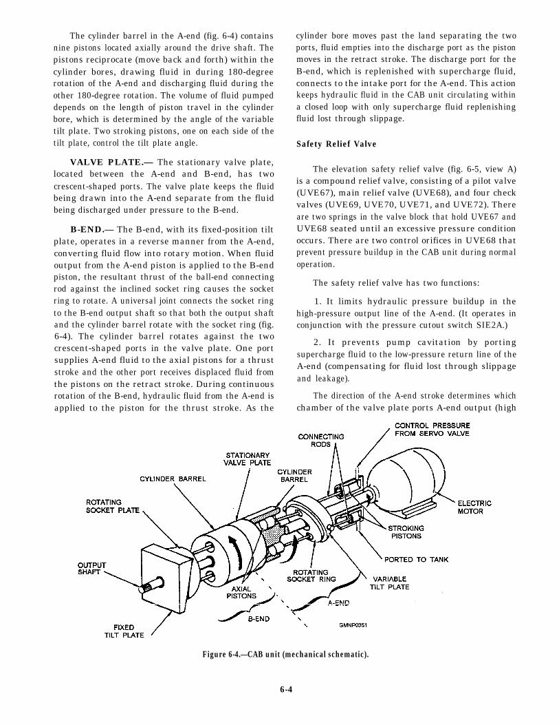
The loader drum holds a total of 20 complete roundsof ammunition. Before an operation, the magazinecrew will load the drum, through the lower hoist, with20 rounds of various types of ammunition. The loaderdrum can also be loaded in the loader drum roomthrough the upper loading station.
Loading Sequence
Usually at the start of a load-and-fire operation, therotating drum already has a compliment of ready serviceammunition. If not, the magazine crew immediately
Figure 6-15.—Filling of the loader drum through the lower hoist.
6-14

begins hand-feeding powder cases and projectiles intothe loading system at the lower hoist (fig. 6-15). Thelower hoist then raises the rounds to the upper loadingstation, where the ejector transfers the rounds into therotating drum.
With a load-and-fire order in effect, the rotatingdrum indexes until a loaded cell reaches the transferstation. At the transfer station, a positioningmechanism aligns the round to the fuze setter mountedoverhead. If the projectile has an MT fuze, the fuzesetter extends (fig. 6-16), sets the fuze, and retracts. Anejector then transfers the round into the upper hoist(fig. 6-17).
With the first round in the upper hoist and the hoistraising, the rotating drum indexes clockwise to bringthe next loaded cell into place. The upper hoist raisesthe first round into the cradle (fig. 6-18), which islatched at the HOIST position. The cradle pawl holdsthe round while the hoist pawl lowers for the secondround. When the hoist pawl is clear of the cradle, the
Figure 6-16.—A round at the transfer station with fuze setterin place setting fuze.
Figure 6-17.—First round in the upper hoist.
Figure 6-18.—First round raised into the cradle.
6-15

cradle unlatches and pivots upward (raises) to align withthe gun bore (fig. 6-19).
The cradle completes the raise cycle and latches tothe slide (fig. 6-20). The rammer extends, driving theround into the breech. At this time, the breechblockpartially lowers (closes) to hold the round in the breech,while the cradle lowers to receive another round.
While the cradle is still raised and after the roundhas been rammed, the rammer retracts, and anotherround is ejected into the upper hoist (fig. 6-21).
With the rammer retracted, the cradle lowers, thebreechblock closes completely, and the empty case traylowers to the FIRE position (fig. 6-22).
With the loading system latched in the FIREposition, the gun fires and recoils (fig. 6-23). Thebreechblock opens, the empty case is ejected into theempty case tray, and another round is raised into thecradle by the upper hoist (fig. 6-24).
As the cradle raises to ram the second round, theempty case tray raises to align with the case ejector (fig.6-25). The empty case is ejected out onto the deck atthe same time the second round is rammed for tiring.
Figure 6-19.—The cradle raises.
Figure 6-20.—Cradle completely up and rammer extending.
Figure 6-21.—Rammer retracting and loader indexing.
6-16

Figure 6-22.—Cradle lowers and empty case tray lowers tothe FIRE position.
Figure 6-23.—The gun fires and recoils.
Figure 6-24.—The breech opens and the empty case is ejected.
Figure 6-25.—The cradle and empty case tray raise to ramthe second round and eject the empty case.
6-17
This completes one firing cycle. The loadingsystem continuously keeps each station full as roundsare fired.
THE 76-MM MK 75 GUN
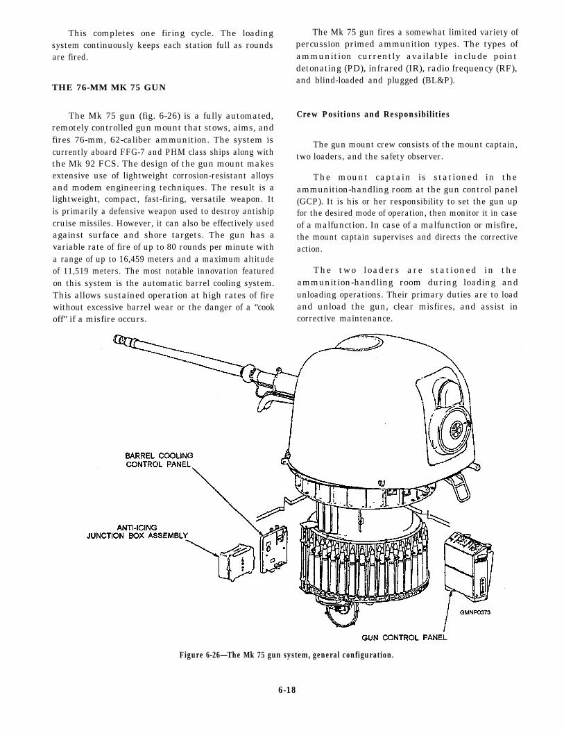
The Mk 75 gun (fig. 6-26) is a fully automated,remotely controlled gun mount that stows, aims, andfires 76-mm, 62-caliber ammunition. The system iscurrently aboard FFG-7 and PHM class ships along withthe Mk 92 FCS. The design of the gun mount makesextensive use of lightweight corrosion-resistant alloysand modem engineering techniques. The result is alightweight, compact, fast-firing, versatile weapon. Itis primarily a defensive weapon used to destroy antishipcruise missiles. However, it can also be effectively usedagainst surface and shore targets. The gun has avariable rate of fire of up to 80 rounds per minute witha range of up to 16,459 meters and a maximum altitudeof 11,519 meters. The most notable innovation featuredon this system is the automatic barrel cooling system.This allows sustained operation at high rates of firewithout excessive barrel wear or the danger of a “cookoff” if a misfire occurs.
The Mk 75 gun fires a somewhat limited variety ofpercussion primed ammunition types. The types ofammunition currently available include pointdetonating (PD), infrared (IR), radio frequency (RF),and blind-loaded and plugged (BL&P).
Crew Positions and Responsibilities
The gun mount crew consists of the mount captain,two loaders, and the safety observer.
The mount captain is stationed in theammunition-handling room at the gun control panel(GCP). It is his or her responsibility to set the gun upfor the desired mode of operation, then monitor it in caseof a malfunction. In case of a malfunction or misfire,the mount captain supervises and directs the correctiveaction.
The two loaders are stationed in theammunition-handling room during loading andunloading operations. Their primary duties are to loadand unload the gun, clear misfires, and assist incorrective maintenance.
Figure 6-26—The Mk 75 gun system, general configuration.
6-18

The safety observer is stationed topside near thegun. His or her responsibility is to monitor the gun andthe area around the gun for any unsafe condition. Thesafety observer is in direct contact with the mountcaptain.
We will now describe the loading system as wewalk through a loading sequence.
Loading Sequence
The ammunition-handling system (fig. 6-27) for theMk 75 gun mount moves ammunition from therevolving magazine to the last station loader drum,where the ammunition is subsequently deposited intothe transfer tray, rammed, and fired. The handlingsystem holds a maximum of 80 rounds. When a roundis fired, each of the other rounds advances one position.
The handling system consists of the revolvingmagazine, the screw feeder and hoist system, the right
and left rocking arm assemblies, and the hydraulicpower unit. The entire loading system moves with the
gun in train. The loader drum, which is a slide-mountedcomponent, moves with the gun in elevation.
The hydraulic power unit, mounted to the carriage,provides hydraulic pressure to operate the loadingsystem.
Ammunition is manually loaded into the revolving
magazine. The revolving magazine consists of twoconcentric circles of stowage cells, each holding 35rounds of ammunition. The revolving magazine turnswhen the hydraulic motor rotates the screw feeder.
Figure 6-27.—The Mk 75 gun-loading system, major components.
6-19

During rotation of the revolving magazine and screw When a round reaches the screw feeder, it is liftedfeeder (fig. 6-28), around moves from the inner circle in a spiraling manner by the hoist lift pawl assembliesof stowage cells to the screw feeder. When a round of the hoist as the screw feeder rotates (fig. 6-29). Theleaves the inner circle of cells, a round from the outer screw feeder, with a capacity of six rounds, delivers acircle replaces it, leaving an empty cell in the outer circle. round to the rocking arms. The rocking arms alternately
Figure 6-28.—Movement of rounds in the revolving magazine and screw feeder.
6-20

Figure 6-29.—Ammunition flow from the revolving magazine through the screw feeder.
6-21
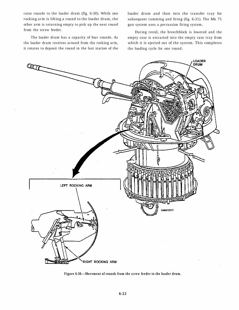
raise rounds to the loader drum (fig. 6-30). While one loader drum and then into the transfer tray forrocking arm is lifting a round to the loader drum, the subsequent ramming and firing (fig. 6-31). The Mk 75other arm is returning empty to pick up the next round gun system uses a percussion firing system.from the screw feeder. During recoil, the breechblock is lowered and the
The loader drum has a capacity of four rounds. As empty case is extracted into the empty case tray fromthe loader drum receives around from the rocking arm, which it is ejected out of the system. This completesit rotates to deposit the round in the last station of the the loading cycle for one round.
Figure 6-30.—Movement of rounds from the screw feeder to the loader drum.
6-22

Figure 6-31.—Movement of rounds in the loader drum.
GUN OPERATION AND MISFIREPROCEDURES
LEARNING OBJECTIVES: Discuss themaintenance, prefire, and misfire requirementsfor current naval guns.
The power and complexity of the gun mounts wejust examined call for a high degree of skill andknowledge on the part of the operator to ensure safe,efficient operation. Gun firing operations are verydynamic in nature. The operator must possess athorough knowledge of the capabilities of the system to
be effective. As mount captain, you will coordinate theactions of your gun crew while controlling the operationof the gun. This includes prefire inspections, gunloading and firing, changing ammunition types,down-loading, and post-fire cleanup. When casualtiesoccur, you will also coordinate the troubleshooting andrepair effort. If a casualty results in a misfire situation,you will supervise the crew in clearing the round fromthe gun. A misfire is the failure of a round ofammunition to fire after the initiating action. Ahangfire is a firing delay beyond the normal ignitiontime after the initiating action. Because of the dangerof a hangfire, you should always wait 30 seconds beforeopening the breech of a gun that has misfired.
6-23
A casualty situation involving a misfire is verydangerous. Having a hot gun further compounds theproblem. A hot gun condition exists when the gunbarrel temperature is raised sufficiently to cause thedanger of ammunition cook off. Cook off occurs whensome ammunition component (powder or projectile)reacts (burns or detonates) due to heat absorbed fromthe walls of the gun barrel. The exact procedure forclearing misfired rounds from the chamber of a gunvaries from one gun to the next and will not be coveredhere. However, we will provide you with a generaloverview of some common elements in the procedure.
While firing, the mount captain monitors how manyrounds have been fired and notifies his or her crew andCIC when a hot gun condition is reached. On a 5"/54gun mount, this occurs after 50 rounds have been firedin 4 hours or less. When a misfire occurs, the mountcaptain notes the time of the misfire, makes additionalattempts to fire using alternate firing circuits, anddetermines if the breechblock is closed. All of thisinformation is passed to CIC and the gun crew. Themount captain then uses a safe clearing time predictorchart to determine if a lo-minute safe clearing timeexists. The time duration of firing and the number ofrounds fired are used to determine whether or not alo-minute safe clearing time exists. If a lo-minute safeclearing time exists, the mount captain then requestspermission from CIC to clear the gun according to theprocedures prescribed in Clearing of Live Ammnitionfrom Guns, SW300-BC-SAF-010. A cold gun iscleared one step at a time, with the mount captaingetting permission from CIC for each step. However,after getting permission to clear the gun in a hot gunsituation, the mount captain takes charge and carries outeach step on his or her own authority while CICmonitors the situation.
It is useful to consider here that a misfire can becaused by a variety of casualties. Given the complexnature of modem gun systems, their firing circuits aredesigned to act as safety interlocks that prevent firinguntil all necessary conditions have been met. The roundmay be chambered and the breechblock closed, but ifall the surrounding equipment is not in place with allthe correct switches energized, the gun will not fire. A
failed or misaligned switch, a sticking or misalignedlatch mechanism, or a faulty control circuit componentcan cause a misfire. Misfires are caused by these typesof casualties often more frequently than by faultyammunition. While a misfire caused by a faulty powdercharge is remedied by replacing it, electronic andmechanical casualties must be diagnosed and repairedbefore firing can resume. Verifying your equipmentposition and checking a few connections at thebeginning of a misfire could save time in clearing thatmisfire. The problem could be as simple as the firinglead having come loose from the firing lock.
While clearing the gun, it must be kept on a safe firebearing. This is to avoid accidentally hitting friendlyforces when clearing the round through the muzzle. Ifthe gun is hot, commence external cooling immediately.External cooling consists of attaching a fire hose to thebarrel at the gun shield so that it sprays cool fire mainwater on the outside of the barrel around where theprojectile is seated. Internal cooling can only be startedafter the propelling charge has been removed. Internalcooling uses a straight applicator that is inserted in thebarrel to spray cooling water around the projectile. Ifthe propelling charge is not removed and happens tocook off with the barrel full of water, the blast woulddemolish the gun.
The exact procedures for clearing misfiredammunition from guns used by the Navy, includingsmall arms, are found in Clearing of Live Ammunitionfrom Guns, SW300-BC-SAF-010. The informationprovided in this manual should not be used as areference for actual operations.
SUMMARY
In this chapter we described gun positioning andfiring equipment. We reviewed the gun systemscurrently in the fleet, focusing on their loading systems.In subsequent chapters we will describe how each ofthese systems is used with a fire control system, howthe systems are aligned, and other maintenancerequirements associated with guns. The chapterconcluded with a discussion of gun operation andmisfire procedures.
6-24