Gun Deck - H.M.S. Flyhmsfly.com/pdf/Gun Deck Planking.pdf · Once the gun deck had been marked for...
22
Page 1 of 22 Gun Deck PLEASE READ GUIDANCE NOTES PRIOR TO FITTING THE GUN DECK This author will incorporate a bowsprit ‘heel and step’ in the forecastle, and will use the design in H.M.S. Victory as a guide, Figure F1. A galley stove will also be added later. Figure F1 – Cut away section of H.M.S Victory (Portsmouth Historic Dockyard) Please check the Addendum; it describes how the keel should have been prepared prior to assembly in 05 - Hull Modifications - Stern Section, page 13. Even thought the hull was assembled, part of the keel as shown in Figure F2, was removed with the use of a fret saw; ensure that 1mm was left proud to be level with the gun deck. The remaining part shown by pencil lines also had to be removed, but the small section on top of the bowsprit hole was left remaining. To achieve this, a junior hacksaw was used with a new blade, Figure F3; it was sawn very gently then removal is relatively simple, but this was not rushed.
Transcript of Gun Deck - H.M.S. Flyhmsfly.com/pdf/Gun Deck Planking.pdf · Once the gun deck had been marked for...

Page 1 of 22
Gun Deck
PLEASE READ GUIDANCE NOTES PRIOR TO FITTING THE GUN DECK
This author will incorporate a bowsprit ‘heel and step’ in the forecastle, and will use the
design in H.M.S. Victory as a guide, Figure F1. A galley stove will also be added later.
Figure F1 – Cut away section of H.M.S Victory (Portsmouth Historic Dockyard)
Please check the Addendum; it describes how the keel should have been prepared prior to assembly in 05 - Hull Modifications - Stern Section, page 13.
Even thought the hull was assembled, part of the keel as shown in Figure F2, was removed with the use of a fret saw; ensure that 1mm was left proud to be level with the gun deck.
The remaining part shown by pencil lines also had to be removed, but the small section on top of the bowsprit hole was left remaining. To achieve this, a junior hacksaw was used with a new blade, Figure F3; it was sawn very gently then removal is relatively simple, but this was not rushed.

Page 2 of 22
Figure F2 – Part of the keel had been removed with a hand fret saw
Figure F3 – A junior hacksaw being used to remove a part of the keel
Page 3 of 22
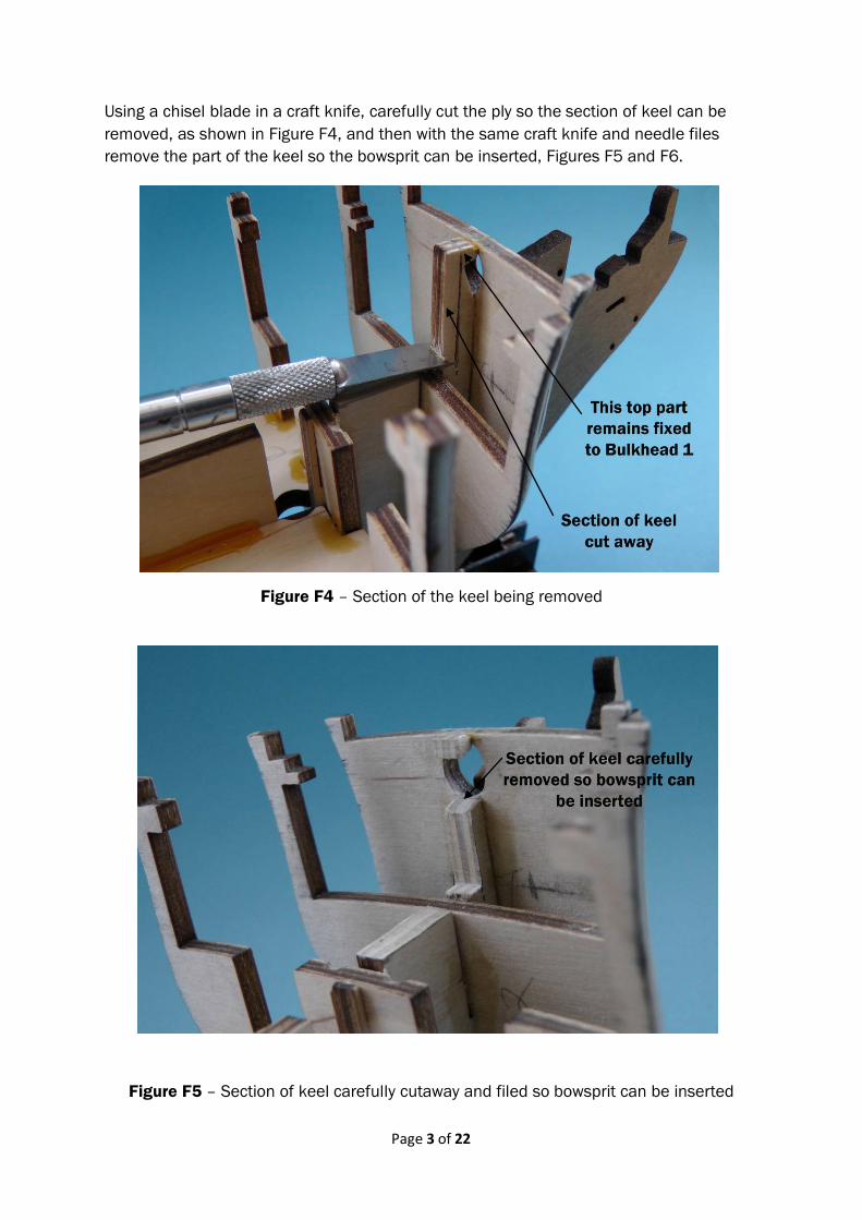
Using a chisel blade in a craft knife, carefully cut the ply so the section of keel can be removed, as shown in Figure F4, and then with the same craft knife and needle files remove the part of the keel so the bowsprit can be inserted, Figures F5 and F6.
Figure F4 – Section of the keel being removed
Figure F5 – Section of keel carefully cutaway and filed so bowsprit can be inserted
Page 4 of 22
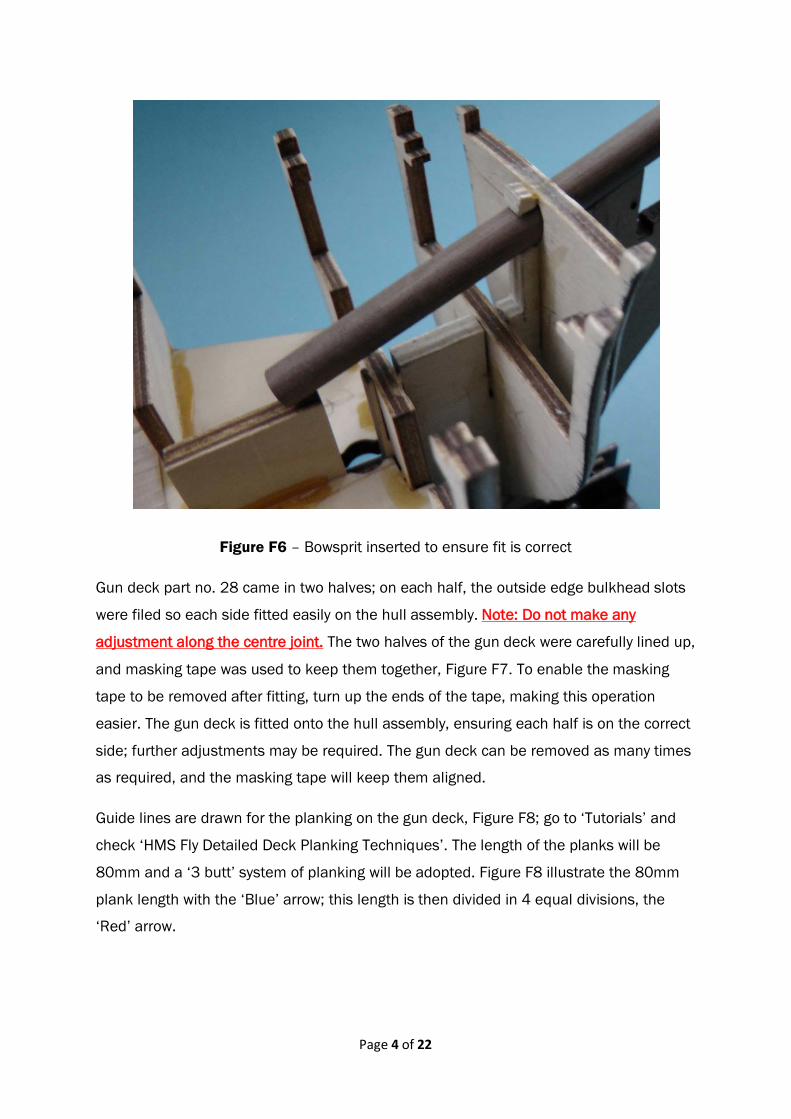
Figure F6 – Bowsprit inserted to ensure fit is correct
Gun deck part no. 28 came in two halves; on each half, the outside edge bulkhead slots
were filed so each side fitted easily on the hull assembly. Note: Do not make any
adjustment along the centre joint. The two halves of the gun deck were carefully lined up,
and masking tape was used to keep them together, Figure F7. To enable the masking
tape to be removed after fitting, turn up the ends of the tape, making this operation
easier. The gun deck is fitted onto the hull assembly, ensuring each half is on the correct
side; further adjustments may be required. The gun deck can be removed as many times
as required, and the masking tape will keep them aligned.
Guide lines are drawn for the planking on the gun deck, Figure F8; go to ‘Tutorials’ and
check ‘HMS Fly Detailed Deck Planking Techniques’. The length of the planks will be
80mm and a ‘3 butt’ system of planking will be adopted. Figure F8 illustrate the 80mm
plank length with the ‘Blue’ arrow; this length is then divided in 4 equal divisions, the
‘Red’ arrow.

Page 5 of 22
Figure F7 – Two halves of the gun deck are held together with masking tape
Figure F8 – Marking up the gun deck ready for planking
Once the gun deck had been marked for planking, the surface is primed with a slightly
diluted PVA adhesive. It was found that through experimentation that when PVA is used
to glue the planks to the ply, there was good contact adhesion between the plank and
the gun deck, when they were applied. The down side to this is that the gun deck slightly
buckles when the PVA had dried; it was placed on a flat surface, and books put on top, to
make it flat again, Figure F9.
Page 6 of 22
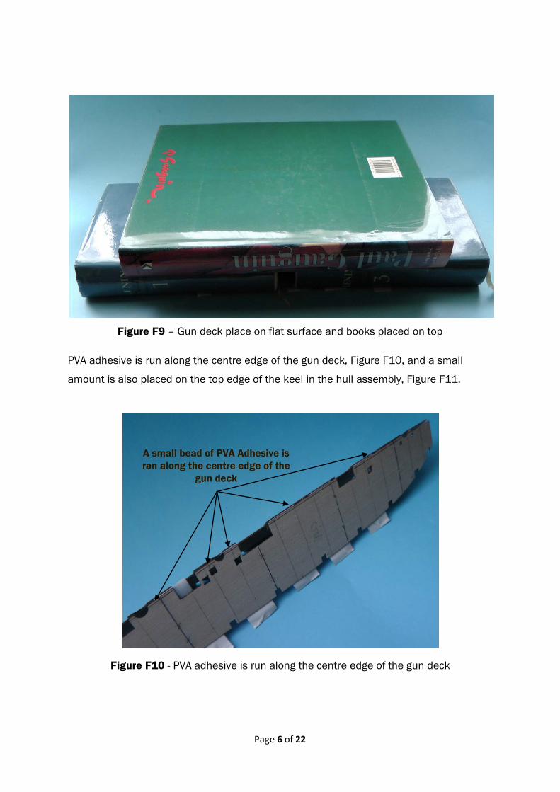
Figure F9 – Gun deck place on flat surface and books placed on top
PVA adhesive is run along the centre edge of the gun deck, Figure F10, and a small
amount is also placed on the top edge of the keel in the hull assembly, Figure F11.
Figure F10 - PVA adhesive is run along the centre edge of the gun deck

Page 7 of 22
Figure F11 – Small bead of PVA adhesive ran along the top edge of the keel
The gun deck is placed on the hull assembly, and masking tape placed along the centre
joint to ensure the two edges are perfectly flat. The gun deck is then fixed in position with
clear tape and spring clips, ensuring that there is full contact along the top edge of all the
bulkheads. The reason that adhesive is only placed along the centre edge of the gun
deck and keel top, is that this will allow plenty of time to fit the gun deck, Figure F12.
Figure F12 – Gun deck positioned onto hull assembly prior to finally gluing into position
Page 8 of 22
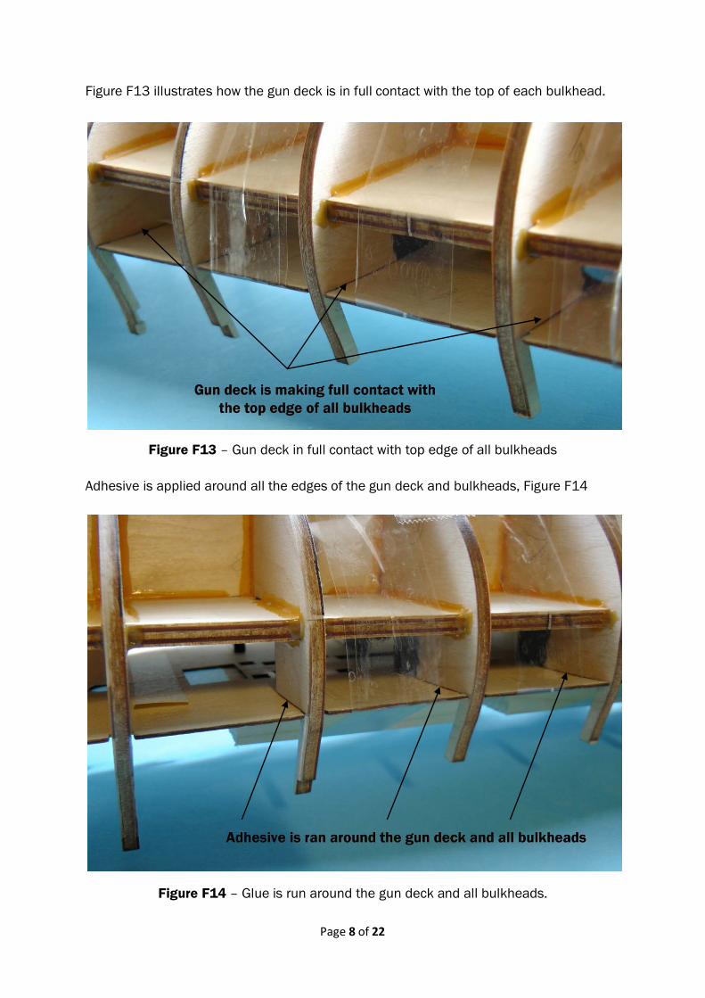
Figure F13 illustrates how the gun deck is in full contact with the top of each bulkhead.
Figure F13 – Gun deck in full contact with top edge of all bulkheads
Adhesive is applied around all the edges of the gun deck and bulkheads, Figure F14
Figure F14 – Glue is run around the gun deck and all bulkheads.

Page 9 of 22
Allow at least 24 hours to ensure that the gun deck is fully fixed in place; then make sure
it is level at both the bow and the stern, where the modifications have taken place. In this
authors model, thin card and ply was used, Figure F15 & F16.
Figure F15 – Card is used to ensure the gun deck is level with modified stern section
Figure F16 – Forward end of the gun deck is made level for planking

Page 10 of 22
The completed gun deck with its slight transverse camber and slight longitudinal
downward curve is illustrated in Figure F17.
Figure F17 – Gun deck fixed to hull assembly
As stated previously, this is the first time this author has built a period ship, and the
planking of the gun deck presented its own challenges for this novice builder. The
sequences of steps now described are not intended for the experienced builder, but for
the novice to gain experience prior to planking the actual gun deck.
Two A4 sheets of paper are fixed with clear sticky tape; then the outline of the gun deck
is drawn, Figure F18. The plank positions are marked on the paper as shown in Figure
F8, and longitudinal 3mm width lines are drawn on one half of the paper to represent the
plank widths, Figure F18.
This author has chosen to start planking the port side (left), following the ‘3 butt’ system
of planking. As each plank is drawn, they will be shaded on the paper using an 8B pencil;
the plank butt ends are drawn in with a black pen.

Page 11 of 22
When doing this one must be very methodical completing each plank run before starting
the next. The ‘3 butt’ system incorporates 4 plank runs, and each set of these have been
marked on the paper, Figure F18
Figure F18 – Illustrates the planking on the port side of the gun deck.
Starting from where the first plank is marked in Figure F18, the port side of the gun deck
is relatively easy to plank, following ‘Tutorials’ - HMS Fly Detailed Deck Planking
Techniques.
The starboard (right) side is a little more difficult to ensure that the plank butts remain in
the same sequence as the port side, and care must be taken that the correct point is
taken to lay the first plank on this side.
Figure F19 illustrates the starting point which this author took to start planking on the
starboard side, which will ensure that the pattern of three planks will be between each
two butts. It does not matter where the first plank is laid providing that it will result in
three planks being between the two butts.
Figure F19 also illustrates the plank laying sequence for each set of 4 plank runs to
complete the ‘3 butt’ system of planking.
This author found that it was much easier to understand this system of planking by fully
drawing out how it will look. Mistakes first made are easily rectified with a rubber, but if
they made when actually planking the gun deck, they will be extremely difficult to correct.
It must be emphasised that it is only this authors approach to learning planking, and
there are many ways to approach this topic.

Page 12 of 22
Figure F19 – Planking of the starboard side of the gun deck
Figure F20 – Aft section of the gun deck

Page 13 of 22
The aft end of the gun deck, Figure F20, again illustrates the ‘3 butt’ system of planking.
This hand drawn plan of the planking will now be used as a guide to plank the actual gun
deck.
Referring to Figure F19, the following sequence of planking is followed on the gun deck:-
(a) Start at 1 on the Centre Line and plank the entire length. This plank starts in
the centre of the hatch, so the other end of the plank is 80 mm forward.
(b) On the PORT side the next run starts at 2
(c) On the STARBOARD side the run will start at 2
(d) On the PORT side the run starts at 3
(e) On the STARBOARD side the run will start at 3
(f) On the PORT side the run will start at 4
(g) On the STARBOARD side the run will start at 4
The planking sequence for ‘3 butt’ system will have been completed once on the PORT
side and once on the STARBOARD side, and the centre plank is common to both
sequences.
AUTHORS NOTE:
Do not mix different plank strips in a run; for example a plank strip is 1,000 mm in
length, and the Fly is approximately 440 mm in length, so the plank strip is sufficient for
two complete plank runs. Do not use the remaining 120 mm in the next plank run. The
width of plank strips can vary, and this will reduce uneven gaps between the planks.
Prior to cutting the planks, one side is marked with a continuous pencil line to ensure a
continuity of grain and colour in two or more plank runs, Figure F21. This is the side the
adhesive is applied.
Figure F21 – A line is drawn on the underside of each plank, and ‘butts’ clearly noted

Page 14 of 22
When a plank is cut, this will form a common butt for two planks; this author used the
notation AA, BB, CC etc. to ensure that the planks were always kept paired, Figure F21.
When applying the adhesive to the underside of the plank, use a minimum amount only;
a small continuous bead of approximately 0.5 mm the full length of the plank was found
to be sufficient producing very little excess adhesive (Figure F19, ‘Tutorials’ - HMS Fly
Detailed Deck Planking Techniques). Should there be any additional adhesive remove
immediately with a craft knife, Figure F22.
Figure F22 – Excess adhesive is removed from plank before it hardens
(This is a test example only)
When laying a plank, make sure one end is firmly pushed into a butt, and then lay the full
length, Figure F23. Press firmly down along its entire length ensuring that the plank is
flush with the adjoining one, but not too hard otherwise the gun deck ply may break,
especially in the centre area.
Figure F23 – Laying a plank ‘butt’ first (This is a test sample only)

Page 15 of 22
Methodically follow the gun deck plan drawn in pencil; as each plank run was completed,
this author drew a yellow pencil line on the plan indicating its completion, Figure F24.
Figure F24 – Each completed plank run is marked on gun deck plan
It is useful to have something to ensure the planks are pressed firmly against each
other. This author used 80 mm brass right angle bar 7mm x 7mm, Figure F25.
Figure F25 – Planks are firmly pushed against each other when first laid
Page 16 of 22
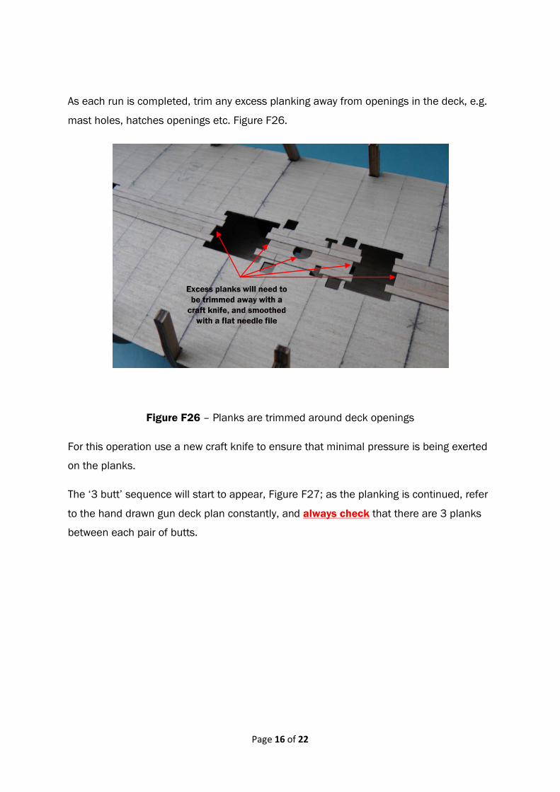
As each run is completed, trim any excess planking away from openings in the deck, e.g.
mast holes, hatches openings etc. Figure F26.
Figure F26 – Planks are trimmed around deck openings
For this operation use a new craft knife to ensure that minimal pressure is being exerted
on the planks.
The ‘3 butt’ sequence will start to appear, Figure F27; as the planking is continued, refer
to the hand drawn gun deck plan constantly, and always check that there are 3 planks
between each pair of butts.

Page 17 of 22
Figure F27 – Three planks start appearing between two ‘butts’
When the area around the bulkheads are planked, special care will be required to ensure
a good fit. For example, Figure F28 illustrates a stern area which is particularly difficult to
plank.
Figure F28 – An area that requires special attention when planking

Page 18 of 22
With the use of a new craft knife and a flat needle file individual planks are shaped
around the bulkheads, Figure F29.
Figure F29 – Planks are cut to fit around bulkhead areas
Figure F30 – Plank is fitted around bulkhead area

Page 19 of 22
Along the edge of the gun deck the plank holding tool cannot be used, and in these
circumstances use a pair of self-closing tweezers to place the plank into the correct
position, Figure F31.
Figure F31 – Self-closing tweezers are used to position planks
The areas around bulkheads nos. 5, 6 & 7 are not planked, as the part of the bulkhead
above the gun deck will be removed once the gun port patterns have been fitted, Figure
F32 (starboard side)
Figure F32 – Areas around bulkheads 5, 6 & 7 are not planked (starboard side)

Page 20 of 22
For this author the planks arranged themselves conveniently around bulkheads 5, 6 & 7
on the starboard side however, the planks on the port side were a little more awkward.
On the port side around bulkhead no. 8, a plank but is just behind the bulkhead,
meaning that the very outer plank could be difficult to fit when the gun port pattern is in
position, Figure F33, so this plank is fitted.
Figure F33 – Plank behind bulkhead no. 8 is fitted
Figure F34 – Plank shaped but not fitted

Page 21 of 22
The other plank behind bulkhead no. 8 is cut to shape but not fitted, Figure F34. To
ensure that this plank is not lost or damaged, it has been fixed to a lollipop stick, Figure
F34.
The planked gun deck is shown in Figures F35 & F36.
Figure F35 – Forward end of the gun deck
Figure F36 – Aft end of the gun deck

Page 22 of 22
The excess planks are carefully cut away from the gun deck, Figure F37.
Figure F37 – Planked gun deck
Lloyd Matthews – April 2013 ©