Guided Procedural Modeling - Purdue Universityhpcg.purdue.edu/bbenes/papers/Benes11EG.pdf · Guided...
10
EUROGRAPHICS 2011 / M. Chen and O. Deussen (Guest Editors) Volume 30 (2011), Number 2 Guided Procedural Modeling B. Beneš † 1 and O.Št’ava 1 and R.Mˇ ech 2 and G.Miller 2 1 Purdue University 2 Adobe Inc. Abstract Procedural methods present one of the most powerful techniques for authoring a vast variety of computer graphics models. However, their massive applicability is hindered by the lack of control and a low predictability of the re- sults. In the classical procedural modeling pipeline, the user usually defines a set of rules, executes the procedural system, and by examining the results attempts to infer what should be changed in the system definition in order to achieve the desired output. We present guided procedural modeling, a new approach that allows a high level of top-down control by breaking the system into smaller building blocks that communicate. In our work we generalize the concept of the environment. The user creates a set of guides. Each guide defines a region in which a specific procedural model operates. These guides are connected by a set of links that serve for message passing between the procedural models attached to each guide. The entire model consists of a set of guides with procedural mod- els, a graph representing their connection, and the method in which the guides interact. The modeling process is performed by modifying each of the described elements. The user can control the high-level description by editing the guides or manipulate the low-level description by changing the procedural rules. Changing the connectivity allows the user to create new complex forms in an easy and intuitive way. We show several examples of procedural structures, including an ornamental pattern, a street layout, a bridge, and a model of trees. We also demonstrate interactive examples for quick and intuitive editing using physics-based mass-spring system. Categories and Subject Descriptors (according to ACM CCS): I.3.3 [Computer Graphics]: Picture/Image Generation—Viewing Algorithms 1. Introduction Procedural modeling means generating content by a pro- cedure or a program, and it is one of the most exciting areas of computer graphics because of the intriguing con- cept of database amplification [Smi84]. However, for nearly twenty years procedural models were used only in their clas- sical areas, such as plants, noise generation [Per85], parti- cle systems, or fractals [EMP * 03]. In the past few years, procedural models have undergone a little renaissance and have found a way into new areas. They are used in urban modeling [ARB07, MWH * 06, WWSR03], and can be com- bined with physics [BCNG10, WOD09], sketching [APS09, IMIM08], and animation [BCNG10]. Among the most important problems of procedural mod- els that hinder their real-life application is the gap between the model description and the control of its execution. The description is usually cryptic, is difficult to understand, and † e-mail:[email protected] involves complicated relations between the model elements, therefore the steps performed when the system is executed are usually beyond imagination. The resulting interaction with a procedural system is thus in the trial-and-error loop. Our key observation is that the concept of environment can be generalized. A complex procedural model does not need to be described as a whole, and it can be divided into simpler blocks that work in parallel, have no direct influence on each other, but can communicate by using an exogenous mechanism, such as Open L-systems. We propose a solution to the problem of low controllabil- ity of the procedural models by defining guided procedural models. The key idea is to divide the space into guides – separate geometrical objects with closed boundaries. Each guide contains one procedural model. Procedural systems inside two separate guides cannot interact directly. Guides are connected by links that serve as message passing mech- anism. When a procedural model inside one guide touches the link, the message is sent to the corresponding guide and c 2010 The Author(s) Journal compilation c 2010 The Eurographics Association and Blackwell Publishing Ltd. Published by Blackwell Publishing, 9600 Garsington Road, Oxford OX4 2DQ, UK and 350 Main Street, Malden, MA 02148, USA.
Transcript of Guided Procedural Modeling - Purdue Universityhpcg.purdue.edu/bbenes/papers/Benes11EG.pdf · Guided...

EUROGRAPHICS 2011 / M. Chen and O. Deussen(Guest Editors)
Volume 30 (2011), Number 2
Guided Procedural Modeling
B. Beneš†1 and O.Št’ava1 and R.Mech2 and G.Miller2
1Purdue University 2Adobe Inc.
Abstract
Procedural methods present one of the most powerful techniques for authoring a vast variety of computer graphicsmodels. However, their massive applicability is hindered by the lack of control and a low predictability of the re-sults. In the classical procedural modeling pipeline, the user usually defines a set of rules, executes the proceduralsystem, and by examining the results attempts to infer what should be changed in the system definition in order toachieve the desired output. We present guided procedural modeling, a new approach that allows a high level oftop-down control by breaking the system into smaller building blocks that communicate. In our work we generalizethe concept of the environment. The user creates a set of guides. Each guide defines a region in which a specificprocedural model operates. These guides are connected by a set of links that serve for message passing betweenthe procedural models attached to each guide. The entire model consists of a set of guides with procedural mod-els, a graph representing their connection, and the method in which the guides interact. The modeling process isperformed by modifying each of the described elements. The user can control the high-level description by editingthe guides or manipulate the low-level description by changing the procedural rules. Changing the connectivityallows the user to create new complex forms in an easy and intuitive way. We show several examples of proceduralstructures, including an ornamental pattern, a street layout, a bridge, and a model of trees. We also demonstrateinteractive examples for quick and intuitive editing using physics-based mass-spring system.
Categories and Subject Descriptors (according to ACM CCS): I.3.3 [Computer Graphics]: Picture/ImageGeneration—Viewing Algorithms
1. Introduction
Procedural modeling means generating content by a pro-cedure or a program, and it is one of the most excitingareas of computer graphics because of the intriguing con-cept of database amplification [Smi84]. However, for nearlytwenty years procedural models were used only in their clas-sical areas, such as plants, noise generation [Per85], parti-cle systems, or fractals [EMP∗03]. In the past few years,procedural models have undergone a little renaissance andhave found a way into new areas. They are used in urbanmodeling [ARB07, MWH∗06, WWSR03], and can be com-bined with physics [BCNG10, WOD09], sketching [APS09,IMIM08], and animation [BCNG10].
Among the most important problems of procedural mod-els that hinder their real-life application is the gap betweenthe model description and the control of its execution. Thedescription is usually cryptic, is difficult to understand, and
† e-mail:[email protected]
involves complicated relations between the model elements,therefore the steps performed when the system is executedare usually beyond imagination. The resulting interactionwith a procedural system is thus in the trial-and-error loop.
Our key observation is that the concept of environmentcan be generalized. A complex procedural model does notneed to be described as a whole, and it can be divided intosimpler blocks that work in parallel, have no direct influenceon each other, but can communicate by using an exogenousmechanism, such as Open L-systems.
We propose a solution to the problem of low controllabil-ity of the procedural models by defining guided proceduralmodels. The key idea is to divide the space into guides –separate geometrical objects with closed boundaries. Eachguide contains one procedural model. Procedural systemsinside two separate guides cannot interact directly. Guidesare connected by links that serve as message passing mech-anism. When a procedural model inside one guide touchesthe link, the message is sent to the corresponding guide and
c© 2010 The Author(s)Journal compilation c© 2010 The Eurographics Association and Blackwell Publishing Ltd.Published by Blackwell Publishing, 9600 Garsington Road, Oxford OX4 2DQ, UK and350 Main Street, Malden, MA 02148, USA.

B. Beneš & O. O.Št’ava & R.Mech & G.Miller / Guided Procedural Modeling
a) b) c)
Figure 1: Guided procedural system used to generate and edit a procedural model of a tree. a) The original tree is generated, b)its guides (lower row) are interactively edited using mass-spring model, and c) some guides are erased and edited individually.
another procedural model is executed. The main advantageof this control is that the user can handle the overall shapeof the entire model by manipulating the guides, whereas thelocal changes are handled on the detailed level of procedu-ral systems. In this way, we allow for "top down" iterativemodeling, where first the overall layout is defined, and thenthe details are added. Another advantage is the simplicity ofthe editing. Instead of manipulating the procedural systemas a whole, we manipulate small blocks separately. Guidescan be connected using a mass-spring system as shown inthe editing sequence Figure 1.
Our paper continues with a description of the previouswork. The method is discussed in Section 3, which is fol-lowed by a description of interactions with the system. Im-plementation and results are in Section 5, and the paper con-cludes with Section 6, which also discusses future work.
2. Previous Work
One of the first areas of procedural models, and proba-bly the most advanced one, includes biological modeling.In his seminal work [Lin68], Lindenmayer introduced par-allel string rewriting systems for a description of cellularsubdivision and endogenous information exchange betweencells. The Lindenmayer systems (L-systems) were extendedin many different directions, from which the most impor-tant present geometrical interpretations of the string lettersand the introduction of special symbols allowing higher lin-ear topological structures via branching [Pru86]. Variousextensions exist, and most of them are summarized in thebook [PL90]. Recent work include Open L-systems that al-
low for exogenous information exchange via query mod-ules [PJM94,MP96]. A feedback system, where an L-systemcan detect positional information and modify it by an in-terpretation of the rules was introduced in [PMKL01] andmultiset L-systems were used to describe the communica-tion of plant ecosystems in [DHL∗98]. Metropolis procedu-ral modeling was introduced in [TLL∗10]. L-systems sharecommon problems of procedural systems, the most relevantto our work being the problem of their controllability.
L-systems are linear as they describe the connection ofone and/or more symbols in a consecutive way. Shape gram-mars [SG71] deal with connecting of 2-D elements andthey define the replacement or the connections of shapes.The concept of shape grammars was recently extendedto applications in urban modeling, where the split gram-mars [WWSR03] were introduced, but the problem of con-trollability is not solved.
Procedural models can be found in the works that con-tribute to computer vision and computer graphics. Müller etal. described a user-assisted system for façade descriptionin [MZWG07]. Fit grammars were applied to urban modelreconstruction from images and point clouds in [HKHF09].and Vanegas et al. matched a predefined set of rules to recon-struct buildings bottom-up from their footprints [VAB10].
Procedural urban modeling has seen an increasing interestin the computer graphics community since a paper [PM01]where the authors used Open L-systems to describe thestreet and road layout that was completed with 3-D mod-els of buildings. Recently Müler et al. [MWH∗06] intro-duced CGA - a grammar-based description of buildings.
c© 2010 The Author(s)Journal compilation c© 2010 The Eurographics Association and Blackwell Publishing Ltd.

B. Beneš & O. O.Št’ava & R.Mech & G.Miller / Guided Procedural Modeling
The procedural generation of street layouts was describedin [CEW∗07], and a procedural generation of roads, tunnels,and bridges was described in [GPMG10]. The controllabil-ity of procedural models is leveraged by user interaction,but in general, the user has limited control over the final re-sults. In [GPMG10], user-sketched graphs of influences de-fine global behavior of the system; local control however,is not available. The interactive editing of procedural rulesin [LWW08] exploits higher levels of user interaction andallows for an immediate visual feedback of the results.
Ijiri et al. introduced a sketching interface to a proceduralmodel in [IOI06]. A parametric procedural rule has the ac-tual values of its formal parameters set by a user sketch. Thisallows for a limited level of control, because the actual mod-eling space is defined by a single rule. Chen et al. [CNX∗08]used Markov processes for sketch-based tree modeling andsurface trees for sketch-based procedural surface modelingwere introduced in [SS08].
Recently, several attempts to combine physically-basedmodeling and procedural systems have appeared. Arvin andHouse [AH02] used a mass-spring model to create architec-tural design with a high level of control over a floor lay-out. This idea was an inspiration for our system, however,we also provide a low-level control by means of embeddedprocedural systems. Moreover, our guides can communicateand do not act independently. Baxter et al. [BCNG10] usedprocedurally built models of plants to interact with physics-based simulations. Procedural models were directly com-bined with physics in [WOD09]. Including physics in theprocedural modeling solves many problems, providing, forexample, realistic and feasible results, but it imposes an extralevel of complexity on the creator of the procedural system.
An important open problem of inverse procedural mod-eling was addressed by [vBM∗10], where the authorsfound a complete L-system for a 2-D vector input. Simi-larly, [BWS10] generates a procedural description of a 3-Dpoint cloud. In the context of urban models [ARB07] recon-structs floor rules from photographs.
3. System Overview
The guided procedural model consists of three basic ele-ments: the guides that are closed shapes, the procedural sys-tems inside the guides, and links that connect the guides andprovide communication among them. Without loss of gener-ality our guides are closed planar polygons. Our proceduralsystems are Open L-systems [MP96] that allow for a widevariety of geometric structures and include an advanced con-trol for exogenous information exchange.
3.1. Guides
Let’s denote the set of guides G = {g1,g2, . . . ,g|G|} and itsindividual elements gi (see Figure 2). Guide gi has its shape
defined by ki vertices vi1,v
i2, . . . ,v
iki
connected with edges
ei1,e
i2, . . .,e
iki
. A set of oriented links is denoted by L = {li j}and we say that the link li j starts in gi and ends in g j . Theguides and the links form an oriented graph H = 〈G,L〉 withvertices G and oriented edges L.
Figure 2: The guided procedural system is a collection ofguides connected with oriented links. Each guide hosts aprocedural system.
The links define topological connectivity of the guides.However, each guide also stores geometrical informationabout the edges from which the links originate and end. Forexample, guide g1 in Figure 2 has two outgoing links: l12starts on edge e1
5 and l13 starts on edge e13. Correspondingly,
guides g2 and g3 store information about the links that con-nect them with the other guides. The finer subdivision of thelower side of guide g1 to edges e1
2, e13, and e1
4 constrains theposition of the link on the guide. To provide a wide varietyof shapes and a global control over the editing process, wecan also define geometric relations between guides. We cansnap guides together; we can define an exact location of theconnection, or we can manipulate the guides using a mass-spring system.
3.2. Open L-systems
An Open L-system is a parallel string rewriting system and isdefined as a tuple P= 〈M,ω,ℜ〉 ,where M is the L-system al-phabet that contains elements A(p1, p2, . . . , pn) called mod-ules. Modules consist of the letters A,B, . . . and their parame-ters p1, p2, . . . pn ∈ R. The symbol ω ∈ M+ (M+ denotes thereflexive closure) is a non-empty initial string of modulescalled the axiom. A set of productions (rules) is denoted byℜ. The rules have form
label : A(p0, p1, . . . , pn) : cond → A∗,
where label is the rule identifier, cond is a boolean expres-sion, and A∗ denotes the reflexive-transitive closure i.e., thelist of all strings including the empty string ε. The symbol →denotes rewriting of the module A(p0, p1, . . . , pn) with thestring on the right side of the rule. The epsilon rule erasesthe symbol A(p0, p1, . . . , pn):
rε : A(p0, p1, . . . , pn)→ ε. (1)
c© 2010 The Author(s)Journal compilation c© 2010 The Eurographics Association and Blackwell Publishing Ltd.

B. Beneš & O. O.Št’ava & R.Mech & G.Miller / Guided Procedural Modeling
The query module has form ?D(p0, p1, . . . , p|P|) and it setsthe parameters pi by values obtained from the environment.An example is module ?D(d) that measures distance to anobstacle. The actual semantics of each query module is de-fined by the designer of the L-system. The list of query mod-ules used in our paper is in Table 2.
Modules are interpreted geometrically by a turtle [Pru86]as described by Table 1 The turtle has a position [x,y] and aheading angle φ that define the turtle’s state (x,y,φ) and theseed of an L-system is a tuple
[(x,y,φ),P = 〈M,ω,ℜ〉].
module interpretation
F(∆) draw a line of length ∆ in the heading dir.f (∆) move in the direction of heading by ∆
+(δ) rotate by δ to the left−(δ) rotate by δ to the right[ push the state on the stack] pop the state from the stack, move to [x,y],
and head in the direction φ
Table 1: Turtle interpretation of the modules.
3.3. Open L-systems and Guides
The geometry produced by the L-system can be limited bythe guide. An element of the L-system can be clipped eitherpartially if its part is outside the guide, or entirely, if its cen-ter is outside. We use the latter solution which allows for apartial overlap with the guide as can be seen in Figure 4.Two or more guides may overlap. However, the embeddedL-systems cannot communicate directly, because the guidesand their L-systems are permitted to communicate only viamessage passing as described below.
We assign at most one L-system to each guide gi. Thiscould seem to be a limiting factor, however, any pair of L-systems P1 = 〈M1,ω1,ℜ1〉 and P2 = 〈M2,ω2,ℜ2〉 can beconverted into one by
P = 〈M1 ∪M2,ω,ℜ1 ∪ℜ2 ∪{ω → [ω1][ω2]}〉 .
We have merged both alphabets and rules, and we have cre-ated a new axiom ω. We have also augmented the rules by anew one that rewrites the new axiom to the sequence of theold axioms ω → [ω1][ω2].
3.3.1. Seeds and Query Modules
Each guide has a set of seeds that define the initial statusof the turtle (its position and heading) and that store the ax-iom ω of an L-system. Multiple seeds are concurrently ex-panded by the set of rules from the defining L-system be-cause all the rules are applied in parallel. Seeds can be cre-ated in two different ways, either interactively by the user, orby receiving a message from another guide via a link.
Our Open L-system has three query modules that allow
the guides to communicate (Table 2). First, a query mod-ule ?DL returns in its parameter d the distance to the closestedge of the guide gi that contains link li j to another guide g j .Second, a query module ?NL returns the distance to the clos-est link in the direction of the actual turtle heading. Third,a query module ?X detects when an L-system crosses theedge that contains a link and returns its ID. It is also used forcollision detection.
The modules ?D and ?N are used to navigate the L-systemto the edge that stores the link that sends a message to an-other guide. The number of steps in which an edge is foundis directed by the user because it depends on the definition ofthe L-system. It can be found in many different ways, for ex-ample deterministically in a single step or by a random walkof the turtle where the result is not guaranteed.
After a link is intersected the module ?X informs the en-vironment (the guide gi) that it should send a message toanother guide as described below.
3.3.2. Message Passing
Sending a Message To provide communication betweenguides, we enhance each link by a set of tokens, a conceptborrowed from Petri Nets [Pet77]. A token is stored on theedge of the start guide gi. When a communication is re-quired, a token is converted into a message that is sent tothe end guide g j associated with the link li j . Two conditionsmust be satisfied to send the message: (1) a token is availableon the link and, (2) the module ?X of the L-system touchesthe edge that contains a link. When the message is sent thenumber of tokens on the edge is decreased.
Multiple modules can concurrently compete for a token.For this problem to be solved, a token on a link can be in oneof three states: free, reserved, or used. A free token is avail-able for any module. However, once a module decides to usethe token, it will change its state to reserved which prohibitsother modules from using it. If the module that reserved thetoken does not reach it, the state is changed back to free.
Figure 3: Link li j between guides g1 and g2. The arrowsindicate the incident angle under which the L-system in g1approaches the edge of the guide and the growth direction ofthe new L-system (turtle heading) in guide g2.
The above-described mechanism for linking the guides istopological. The geometry of the connection is defined bythe user when the link is defined. The incident direction ofthe turtle, the vector the L-system attempts to match, is givenwhen the link between the two guides is defined as shown in
c© 2010 The Author(s)Journal compilation c© 2010 The Eurographics Association and Blackwell Publishing Ltd.

B. Beneš & O. O.Št’ava & R.Mech & G.Miller / Guided Procedural Modeling
module input output description
?DL, ?DG, ?DA idtest f ound, d, β, Distance to a link. An optional input is an id idtest . Parameter d is theidout distance to the closest link, guide, or element of the given idtest (or any
if idtest is not set), the angle β to the closest point, and the idout of theclosest object. If no such element exists, the parameter f ound is set to 0.
?NL, ?NG, ?NA idtest f ound, d, idout Forward distance. An optional input is an id idtest . Parameter d is thedistance to the closest link, guide, or element of the given idtest (or anyif idtest is not set) in the turtle direction, and the idout of the closestobject. If no such element exists, the parameter f ound is set to 0.
?X ∆, idin, f ound, idout Collision detection. The input is the length ∆ of an element to be testedidtest for collision. Optionally, an id idin can be associated with the object. The
collision test can be restricted to an object with an id idtest . The parameterf ound is set to 1 if there is a collision, in which case the id idout is set tothe id of the intersecting element, guide, or a link.
Table 2: Communication modules of our Open L-systems. An input parameter not listed is passed through unchanged.
Figure 3. Note that the parameters of the module X as it in-tersects the link are available in the seed module in the endguide. This way the L-system can send additional informa-tion through the link.
Receiving a Message When the end guide g j receives amessage, it seeds an L-system on the receiving edge. Theseeded L-system is defined by the user when the system iscreated simply by dragging the L-system from the menu tothe guide. The exact location of the seed on the edge is de-fined by the intersection point on the starting edge, and theheading direction is defined by the definition of the link asdepicted in Figure 3. In this way we can make the transitionbetween edges of two guides C0 or C1 continuous.
The condition of seeding the L-system on an exact loca-tion of the edge is not restrictive because the L-system canperform a linear transformation by executing the rule
A →+(α) f (∆).
3.3.3. L-systems Execution
Let’s recall that the guided procedural model is stored asan oriented graph H = 〈G,L〉 with vertices G and orientededges L. There are two kinds of seeds possible in each guide.Explicit seeds are defined by the user, and implicit seeds re-sult from a message passed from another guide.
We create a set of active L-systems that are being ex-ecuted, which we denote by Le. This set is initialized bythe explicitly defined seeds. We execute all the L-systemsin the guides from Le in parallel using a technique similarto [LWW09]. If the message-passing module ?X touches anedge, we add the generated seed into the Le and execute itimmediately. This process repeats until Le is not empty. Be-cause the number of tokens is finite, the procedure will fin-ish in finite time. New seeds can be created while anotherL-system is already being executed.
3.3.4. L-systems Update
The L-systems in a guide may require recalculation. This canhappen when an interactive operation with the guide occurs,if there is a change of the structure of links, or if it is re-quested manually by the user. When the update of a guide isrequired, we perform a local incremental update of the guideand its children. We first erase all of the L-systems in theguide, and reset the explicit seeds as well as the tokens onthe edges. The L-systems of all included seeds are then re-calculated in parallel, regardless of whether they are implicitor explicit. Messages are sent to all dependent guides andtheir L-systems are recalculated in the same way.
The communication overhead is negligible compared tothe time required to recalculate the L-systems. However,only a part of the model is recalculated, so our approach isfaster than calculating the entire model from the scratch aswould be the case of a single procedural model.
4. Interaction
The main objective of user interaction is a minimal, intuitive,easy-to use way creation and manipulation of guides. TheL-systems can be created beforehand, stored as XML files,loaded at the beginning of the execution, and available froma drag-and-drop menu. We have created various proceduralmodels that we show in Section 5 and on the video.
4.1. Guides and Links Definition and Editing
Creating a guide is done by entering the vertices of the in-put polygon. The seeds of the L-systems are then definedinteractively as a position and orientation, and the L-systemis attached from a menu. Once the guides are defined, theirlinks are created by clicking inside a guide and crossing thecorresponding edge. This operation is done twice, first forthe start guide, then for the end guide. The number of asso-ciated tokens can be set from a menu.
Our system allows interactive translation, rotation, and
c© 2010 The Author(s)Journal compilation c© 2010 The Eurographics Association and Blackwell Publishing Ltd.

B. Beneš & O. O.Št’ava & R.Mech & G.Miller / Guided Procedural Modeling
scaling of the guides. These operations can be performedbefore the L-system execution for fine-tuning the shapes. Ifthey are applied after the L-system execution, the guides areupdated using the mechanism described in Section 3.3.4.
Manual manipulation of guides can be tedious if a largechange is required. To simplify this, our system also allowsfor higher-level operations with guides. Guides can be at-tached to each other by use of a snap operation.
4.2. Mass-Spring Editing
Another feature that allows for high-level guide editing is aphysics-based mass-spring system [WB97]. Vertices of theguides are treated as particles with mass, and the edges assprings with the resting length set to their initial lengths. Se-lected vertices of each guide are also connected by diagonalsprings to better preserve the shape of the guides. When twoguides are snapped together, their particles and springs areshared on the overlapping vertices and edges. Guides thatare not located next to each other may require a hard linkthat does not change. This is provided by user-defined stiffsprings between the guides. In this way two links will notmove relatively to each other when edited.
When editing the guide, we select a particle and we con-strain its relative position to the position of the mouse. Thepositions of the remaining particles are then obtained from asolution of the mass-spring system.
5. Implementation and Results
We have implemented our system in C++ with the sup-port for OpenGL visualization. All examples were gener-ated on an Intel R© Xeon R© CPU E5530 quad core runningat 2.4GHz. The computer is equipped with 12GB of memoryand NVIDIA R© GTX 480 GPU with 1.5GB of memory.
The creation of L-systems in the examples presented be-low took 30 minutes to 1 h for each, based on their complex-ity. Writing an L-system is still a difficult task, however, eachL-system is created and edited separately, and it can use thelinks and guide edges to guide the growth in a desired direc-tion. Thus this task is significantly simplified as comparedto the editing of a large L-system, in which the overall shapeand local behavior are hard to control. The creation of theguides and their connection took less than 3 minutes. Thefine-tuning of the guides communication took less than 10minutes in the most complicated case in Section 5.4.
The L-systems are stored in an XML file and each isabout 10-30 lines long. The most complicated L-system has11 rules. The response of the system depends on the rules,the number of seeds, the number of concurrently runningL-systems, and the number of their elements. If a large num-ber of elements is used and a large number of collisions ischecked, the system slows down as it did in the example inFigure 7, where more than 85,000 elements were used and
the generation of the model took 45 seconds. For most of theother examples, this took less than one second. The actualbottleneck of the application is the collision detection, so weuse kd-trees to speed-up the collision detection. On the otherhand, collisions are checked only within the elements insideeach guide and not with all the elements in the scene, there-for the guides implicitly simplify the collision detection.
5.1. Palm Tree
The example in Figure 4 shows guided growth, where multi-ple guides with simple L-systems and intuitive connectionsare used to create the structure.
a) b) c)
Figure 4: A structure generated by two simple L-systems(trunk and leaves) and a set of guides. a) The original guidelayout and the generated structure. b) The new structure iscreated by modifying the guides. c) The resulting structure isgenerated by re-running the same procedural model.
Figure 4 a) shows the set of guides and the generatedstructure, and Figure 4 b) shows the modified guides. Wefind that the palm shape can be easily controlled top-downby changing the shape of the guide without actually modi-fying the underlying L-systems. A similar structure could begenerated bottom-up by a single L-system; however, makingthe local changes would require complicated modification ofthe rules. The single L-system would also be more compli-cated. The rules that produce our structure are rather simple.The set of rules for the trunk guides is:
(1) ?seed(pos,α)→+(α)[?DL(∆)]
(2) ?DL( f ound,β,∆) : f ound →
+(β∗0.5)?X(∆) f (∆)?DL(∆)
(3) ?DL( f ound)→ ε
(4) ?X( f ound,∆) : f ound → F(∆)cut
(5) ?X( f ound,∆)→ F(∆)
The L-system grows a palm trunk from the seed point towardthe link to the next guide. The first rule rotates the turtle bythe angle α given by the seed and inserts the query symbol?DL which queries the direction to a link. The symbol ?DL
has a parameter ∆ that stores the desired length of a segment.The parameter f ound of the symbol ?DL is set to one if alink is found. In this case, rule (2) creates a new symbol ?X
c© 2010 The Author(s)Journal compilation c© 2010 The Eurographics Association and Blackwell Publishing Ltd.

B. Beneš & O. O.Št’ava & R.Mech & G.Miller / Guided Procedural Modeling
rotated towards the link by a half the angle β between thedirection to the link and the current turtle orientation. Rule(3) stops growth if a link is not found. The parameter f oundof the symbol ?X is set to one if there is a collision with theguide. In this case rule (4) is applied, the growth stops, thetrunk segment F(∆) of the length ∆ is inserted, and the restof the string is cut. A symbol that intersects a guide initiatesthe link and thus the seed in the linked guide. Rule (5) placesa trunk segment F if there is no collision.
Once the growth reaches guides for compound leaves, thesecond L-system is executed in each of these guides. The setof rules for the compound leaf guides is
(1) ?seed(pos,αLINK)→+(α)[?DL(∆)]
(2) ?DL( f ound,d,β,∆) : f ound →
+(β)?X(∆,d) f (∆)?DL(∆)
(3) ?DL( f ound) → ε
(4) ?X( f ound) : f ound → cut
(5) ?X( f ound,∆,d)→ F(∆)L(d,∆∗5)
(6) L(d,∆) : d > 0.1 → [+(60)E(∆)][−(60)E(∆)]
(7) L(d,∆)→ [+(600∗d)E(∆)][−(600∗d)E(∆)]
Rules (1-5) have a similar function as in the previous L-system. In rule (2) the distance d to the link, returned bysymbol ?DL, is stored with the symbol ?X . Rule (5) createsan additional module L that puts leaf blades E on the branch,using rules (6-7). Rule (6) places two opposite blades at 60o
angle, as long as the distance d to the link is above 0.1. Rule(7) is applied for d ≤ 0.1 and it gradually reduces the bladeangle from 60o to zero as the stem approaches the link. Rules(2-5) act as global environment sensor. As depicted in Fig-ure 4, the L-system tends to grow to the link on the oppositeside of the guide. However, this link has no token and there-fore produces no messages. It is used only as a navigationof the L-system growth. The runtime of the model was 0.11second with 481 elements in the final image.
5.2. Spirals
A more complex example in Figure 5 shows a spiral thatinitiates lateral spirals in the attached guides. The spiral inthe main guide is generated by an L-system that has 11 rules,but the core functionality is captured by the following two:
(1) ?NA( f ound,d,∆) : f ound AND d > ∆∗10 →
+(15∗∆0/d)?X(∆) f (∆)?NA(∆∗0.995)
(2) ?NA( f ound,d,∆) : f ound AND d > ∆0/3 →
+(50∗∆0/d)?X(∆) f (∆)?NA(∆∗0.995)
The tip of the spiral senses the distance to the nearestguide boundary or the nearest element in the guide in thecurrent turtle direction using the symbol ?NA. The growth di-rection is changed by an angle that is inversely proportional
Figure 5: A spiral generated by two simple L-systems anda set of guides. The main spiral spawns a lateral branchwhen it sees the proximity of a link. When the lateral branchtouches the link, it sends a message to the end guide thatgenerates another spiral.
to the returned distance d. Moreover, when the spiral gets tooclose to another element the angle increases in rule (2). Thenew segment is shorter by a factor of 0.995. If a collision isdetected or the segment becomes shorter than the third of theinitial length ∆0 the growth stops.
Other rules are used to sense the closest edge that containsa link. If the edge is within its proximity, it sends a lateralbranch to it. When the branch reaches the edge, it sends amessage to the other guide which generates another spiral.A feedback loop mechanism is also implemented to avoidmultiple branches reaching one edge. Once a branch is sentto an edge, no more branches are generated to the link withthe same ID by marking the token as reserved.
The lateral guides have a simplified version of the same al-gorithm for spiral generation that does not provide the mech-anism for sending lateral branches. The second L-system hasonly 7 rules. The total time to generate this example was 8seconds with 1,900 elements in the scene.
5.3. Dinosaur
The dinosaur from Figure 6 was inspired by [MP96] and hasbeen created by two L-systems. One was used for legs, theneck, and the tail. It grows segments that follow the guide,similarly to the mechanism captured by the two rules inthe previous section that are modifying the growth directionbased on the distance to an edge. The leaves in the body, thehead, and the tail tip are created at random positions, andtheir rotations and colors are also randomized.
c© 2010 The Author(s)Journal compilation c© 2010 The Eurographics Association and Blackwell Publishing Ltd.
B. Beneš & O. O.Št’ava & R.Mech & G.Miller / Guided Procedural Modeling
Figure 6: The overall layout of this structure is controlledby the guides (upper image), and the inner structure is gen-erated by two simple L-systems.
This is an example, in which the guided procedural mod-eling enabled the modeler to capture the result by usingmuch simpler L-systems compared to a complicated L-system of a branching structure that would try to grow intothe dinosaur’s neck and tail. The entire structure was gener-ated in 2 seconds and contains more than 10,000 elements.
5.4. Urban Layout
Figure 7 shows an image of an automatically created ur-ban layout. This example was inspired by the paper [PM01]where the authors used Open L-systems to describe a street-and-road layout that was completed with 3-D models ofbuildings. The layout has five guides, and the executionstarts in the middle with the star like street layout that sendsa large number of tokens over the edges to the neighboringguides that create regular patterns.
Figure 7: A guided procedural system generated this com-plex urban layout, while street continuity across the guidesis provided by passing messages.
The L-system to generate the circular street layout has 51lines and 9 rules, and the rectangular has 29 lines with 4rules. The circular layout generates, in parallel, five arterialstreets in a star like pattern. They generate circular arterialstreets that automatically detect the corresponding points onthe neighboring arteries and attempt to connect to them. All
arterial streets can detect edges with a link and send mes-sages to the neighboring guide. If this happens, the nextguide starts another arterial street that continues in the samedirection. In contrast, the second guide generates a regularpattern. Once the arterial street cannot continue, it executesa rule that generates a simple rectangular layout of parcels.
This is the most resource-demanding example. Every rulehas a query symbol that detects distance to an intersection,and one that detects edges with links. The total number of el-ements generated in 70 iterations was 85,000, the maximumnumber of checked collisions was 6 million, and the maxi-mum time required to regenerate the model was 45 second.
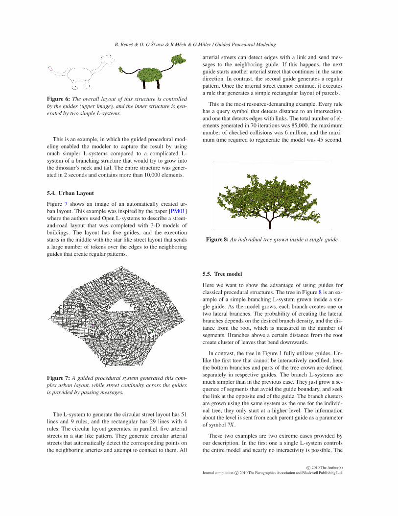
Figure 8: An individual tree grown inside a single guide.
5.5. Tree model
Here we want to show the advantage of using guides forclassical procedural structures. The tree in Figure 8 is an ex-ample of a simple branching L-system grown inside a sin-gle guide. As the model grows, each branch creates one ortwo lateral branches. The probability of creating the lateralbranches depends on the desired branch density, and the dis-tance from the root, which is measured in the number ofsegments. Branches above a certain distance from the rootcreate cluster of leaves that bend downwards.
In contrast, the tree in Figure 1 fully utilizes guides. Un-like the first tree that cannot be interactively modified, herethe bottom branches and parts of the tree crown are definedseparately in respective guides. The branch L-systems aremuch simpler than in the previous case. They just grow a se-quence of segments that avoid the guide boundary, and seekthe link at the opposite end of the guide. The branch clustersare grown using the same system as the one for the individ-ual tree, they only start at a higher level. The informationabout the level is sent from each parent guide as a parameterof symbol ?X .
These two examples are two extreme cases provided byour description. In the first one a single L-system controlsthe entire model and nearly no interactivity is possible. The
c© 2010 The Author(s)Journal compilation c© 2010 The Eurographics Association and Blackwell Publishing Ltd.

B. Beneš & O. O.Št’ava & R.Mech & G.Miller / Guided Procedural Modeling
second case allows a very high level of control. Simpler L-systems are specified as well as their communication. Thereis virtually a continuous scale between these two cases, andit is the user’s decision how much detail in the structure ofthe guides is necessary.
5.6. Mass-Spring Interaction
The existence of several guides defining the shape makes itpossible to interactively adjust it by manipulating the guideswithout changing the L-systems. Figure 1 shows modifica-tions of the tree model from the previous section using ourinteractive mass-spring system. Figure 1 a) shows the origi-nal image. In Figure 1 b) the structure of the edges was con-verted into a mass-spring system. Each edge is substitutedby a spring and the user provided a set of interactive opera-tions. Figure 1 c) shows the tree, where one guide was erasedand two were scaled up. The tree has approximately 15,000elements and its generation takes about 2 seconds. We referto the video for examples of the interactive tree editing.
The last example in Figure 9a) shows a suspension bridgedefined with three L-systems. One L-system creates thebridge tower, another one the bridge span by placing a set ofbeams at a different given cross angles. The third L-systemdefines the main cable with vertical cables placed a fixedhorizontal distance. The guides control the placement of thetwo towers and the lower part of the bridge. The guides forthe main cable are snapped together and the overall shapeof the main cable can be changed by moving a cable guide.The position of the remaining guides is adjusted using thephysics simulation. The L-systems inside the guides regen-erate the horizontal cables at the desired spacing, regardlessthe shape of curve formed by the main cable. Figure 9b)shows a result after moving just a few guides.
a)
b)
Figure 9: An example of a suspension bridge, defined withguided procedural model with three simple L-systems.
6. Conclusions and Future Work
We have presented guided procedural modeling imple-mented as guided Open L-systems that extends the conceptof procedural models with exogenous control by generaliz-ing the concept of environment. Instead of considering theenvironment as a single entity, we have divided it into mutu-ally exclusive worlds, called guides that can communicatevia message passing. The content of the message defineswhen and where a new L-system is created. The main ad-vantages of our concept are the "top down" approach to mod-eling and the simplicity of the user control, addressing twoof the main open problems of procedural systems. Instead ofone large L-system, the user creates a much simpler set of L-systems that can be edited and tuned individually. The useralso defines how the guides communicate with each other.
Our system has various limitations. It is easier to createand manipulate L-system models in our system, but it doesnot eliminate the need of manually writing the L-system pro-ductions. Although the L-systems are simple, extra attentionis needed to support the communication with guides. In ad-dition, there may be models that do not lend themselves tobe used in our system. For example, if an upper branch of atree should reduce the amount of light received by a lowerbranch that is defined in another guide an extra communica-tion between guides would be necessary.
There are several avenues for future work. An obviousone is an extension of our system into 3-D. However, spe-cial care will be necessary to determine growth directionsand also the interactive system would be more complicated.Another extension would be incorporating the concept ofguides into a recently introduced procedural system usedin urban modeling, such as CGA [MWH∗06], split gram-mars [WWSR03], or shape grammars [SG71]. Another av-enue for future work is recognizing guides in the process ofinverse procedural modeling [vBM∗10, BWS10]. Analogi-cally to multifractals [Har01], a scene does not need to be theresult of a single procedural model but it could be a compo-sition. Also, in our system we have showed one level of mes-sage passing between guides. Apparently, this process couldbe done on multiple levels of hierarchy, but this could alsocomplicate the user design. Last but not least, a user study toshow the feasibility of design could be done.
Acknowledgements
We would like to thank NVIDIA for providing free graph-ics hardware. This work has been supported by NSF IIS-0964302 Integrating Behavioral, Geometrical and Graph-ical Modeling to Simulate and Visualize Urban Areas andAdobe Inc. grant Constrained Procedural Modeling.
c© 2010 The Author(s)Journal compilation c© 2010 The Eurographics Association and Blackwell Publishing Ltd.

B. Beneš & O. O.Št’ava & R.Mech & G.Miller / Guided Procedural Modeling
References
[AH02] ARVIN S. A., HOUSE D. H.: Modeling architectural de-sign objectives in physically based space planning. Automationin Construction 11, 2 (2002), 213 – 225. 3
[APS09] ANASTACIO F., PRUSINKIEWICZ P., SOUSA M. C.:Sketch-based interfaces and modeling: Sketch-based parameteri-zation of L-systems using illustration-inspired construction linesand depth modulation. Comput. Graph. 33, 4 (2009), 440–451. 1
[ARB07] ALIAGA D. G., ROSEN P. A., BEKINS D. R.: Stylegrammars for interactive visualization of architecture. IEEETransactions on Visualization and Computer Graphics 13, 4(2007), 786–797. 1, 3
[BCNG10] BAXTER R., CRUMLEY Z., NEESER R., GAIN J.:Automatic addition of physics components to procedural con-tent. In AFRIGRAPH ’10: Proceedings of the 7th InternationalConference on Computer Graphics, Virtual Reality, Visualisationand Interaction in Africa (New York, NY, USA, 2010), ACM,pp. 101–110. 1, 3
[BWS10] BOKELOH M., WAND M., SEIDEL H.-P.: A connec-tion between partial symmetry and inverse procedural modeling.ACM Transactions on Computer Graphics (2010), 1–10. 3, 9
[CEW∗07] CHEN G., ESCH G., WONKA P., PASCAL, ZHANG
M. E.: Interactive procedural street modeling. ACM Trans.Graph. 27, 3 (2007), 35. 3
[CNX∗08] CHEN X., NEUBERT B., XU Y.-Q., DEUSSEN O.,KANG S. B.: Sketch-based tree modeling using markov randomfield. ACM Trans. Graph. 27 (December 2008), 109:1–109:9. 3
[DHL∗98] DEUSSEN O., HANRAHAN P., LINTERMANN B.,MECH R., PHARR M., PRUSINKIEWICZ P.: Realistic model-ing and rendering of plant ecosystems. ACM, New York, NY,USA, 1998, pp. 275–286. 2
[EMP∗03] EBERT D. S., MUSGRAVE F. K., PEACHEY D., PER-LIN K., WORLEY S.: Texturing and Modeling, 3rd ed. AcademicPress, Inc., Orlando, FL, USA, 2003. 1
[GPMG10] GALIN E., PEYTAVIE A., MARÉCHAL N., GUÉRIN
E.: Procedural generation of roads. Computer Graphics Forum(Proceedings of Eurographics) 29, 2 (2010), 429–438. 3
[Har01] HARTE D.: Multifractals: Theory and Applications.Chapman and Hall/CRC, 2001. 9
[HKHF09] HOHMANN B., KRISPEL U., HAVEMANN S., FELL-NER D.: Cityfit - high-quality urban reconstruction by fittingshape grammars to image and derived textured point clouds. InProceedings of 3D-ARCH 2009 (2009). 2
[IMIM08] IJIRI T., MECH R., IGARASHI T., MILLER G.:An example-based procedural system for element arrangement.Comput. Graph. Forum 27, 2 (2008), 429–436. 1
[IOI06] IJIRI T., OWADA S., IGARASHI T.: The sketch l-system:Global control of tree modeling using free-form strokes. In InSmart Graphics (2006), pp. 138–146. 3
[Lin68] LINDENMAYER A.: Mathematical models for cellular in-teraction in development. Journal of Theoretical Biology Parts Iand II, 18 (1968), 280–315. 2
[LWW08] LIPP M., WONKA P., WIMMER M.: Interactive vi-sual editing of grammars for procedural architecture. SIGGRAPH’08: ACM SIGGRAPH 2008 papers (2008), 1–10. 3
[LWW09] LIPP M., WONKA P., WIMMER M.: Parallel genera-tion of l-systems. Vision, Modeling, and Visualization Workshop(Nov. 2009). 5
[MP96] MECH R., PRUSINKIEWICZ P.: Visual models of plantsinteracting with their environment. In SIGGRAPH ’96: Pro-ceedings of the 23rd annual conference on Computer graphics
and interactive techniques (New York, NY, USA, 1996), ACM,pp. 397–410. 2, 3, 7
[MWH∗06] MÜLLER P., WONKA P., HAEGLER S., ULMER A.,GOOL L. V.: Procedural modeling of buildings. In SIGGRAPH’06: ACM SIGGRAPH 2006 Papers (New York, NY, USA, 2006),ACM Press, pp. 614–623. 1, 2, 9
[MZWG07] MÜLLER P., ZENG G., WONKA P., GOOL L. V.:Image-based procedural modeling of facades. In SIGGRAPH’07: ACM SIGGRAPH 2007 papers (New York, NY, USA, 2007),ACM, p. 85. 2
[Per85] PERLIN K.: An image synthesizer. SIGGRAPH Comput.Graph. 19, 3 (1985), 287–296. 1
[Pet77] PETERSON J. L.: Petri nets. ACM Comput. Surv. 9, 3(1977), 223–252. 4
[PJM94] PRUSINKIEWICZ P., JAMES M., MECH R.: Synthetictopiary. In SIGGRAPH ’94: Proceedings of the 21st annual con-ference on Computer graphics and interactive techniques (NewYork, NY, USA, 1994), ACM Press, pp. 351–358. 2
[PL90] PRUSINKIEWICZ P., LINDENMAYER A.: The Algorith-mic Beauty of Plants. Springer–Verlag, New York, 1990. 2
[PM01] PARISH Y. I. H., MÜLLER P.: Procedural modeling ofcities. In SIGGRAPH ’01: Proceedings of the 28th annual con-ference on Computer graphics and interactive techniques (2001),ACM Press, pp. 301–308. 2, 8
[PMKL01] PRUSINKIEWICZ P., MÜNDERMANN L., KAR-WOWSKI R., LANE B.: The use of positional information inthe modeling of plants. In SIGGRAPH ’01: Proceedings of the28th annual conference on Computer graphics and interactivetechniques (New York, NY, USA, 2001), ACM, pp. 289–300. 2
[Pru86] PRUSINKIEWICZ P.: Graphical applications of l-systems.In Proceedings on Graphics Interface ’86/Vision Interface ’86(Toronto, Ont., Canada, Canada, 1986), Canadian InformationProcessing Society, pp. 247–253. 2, 4
[SG71] STINY G., GIPS J.: Shape grammars and the generativespecification of painting and sculpture. In Segmentation of Build-ings for 3DGeneralisation. In: Proc. of the Workshop on gener-alisation and multiple representation , Leicester (1971). 2, 9
[Smi84] SMITH A. R.: Plants, fractals, and formal languages. InSIGGRAPH ’84: Proceedings of the 11th annual conference onComputer graphics and interactive techniques (New York, NY,USA, 1984), ACM Press, pp. 1–10. 1
[SS08] SCHMIDT R., SINGH K.: Sketch-based procedural sur-face modeling and compositing using Surface Trees. ComputerGraphics Forum 27, 2 (2008), 321–330. 3
[TLL∗10] TALTON J., LOU Y., LESSER S., DUKE J., MECH
R., KOLTUN V.: Metropolis procedural modeling. ACM Trans.Graphics (2010). 2
[VAB10] VANEGAS C. A., ALIAGA D. G., BENEŠ B.: Buildingreconstruction using manhattan-world grammars. In Proceedingsof IEEE Conference on Computer Vision and Pattern Recognition(CVPR) (2010), p. 8. 2
[vBM∗10] ŠTAVA O., BENEŠ B., MECH R., KRIŠTOF P.,ALIAGA D. G.: Inverse proc. modeling by automatic generationof L-systems. Comp. Graph. Forum 29:2 (2010), 10. 3, 9
[WB97] WITKIN A., BARAFF D.: Physically based modeling:Principles and practice. Siggraph Course Notes, 1997. 6
[WOD09] WHITING E., OCHSENDORF J., DURAND F.: Proce-dural modeling of structurally-sound masonry buildings. ACMTransactions on Graphics 28, 5 (2009), 112. 1, 3
[WWSR03] WONKA P., WIMMER M., SILLION F., RIBARSKY
W.: Instant architecture. ACM Trans. Graph. 22, 3 (2003), 669–677. 1, 2, 9
c© 2010 The Author(s)Journal compilation c© 2010 The Eurographics Association and Blackwell Publishing Ltd.