Guided compact cylinder 1 - · PDF fileoil resistant NBR rubber nickel plated steel Function...
81
Transcript of Guided compact cylinder 1 - · PDF fileoil resistant NBR rubber nickel plated steel Function...
1
2
3
4
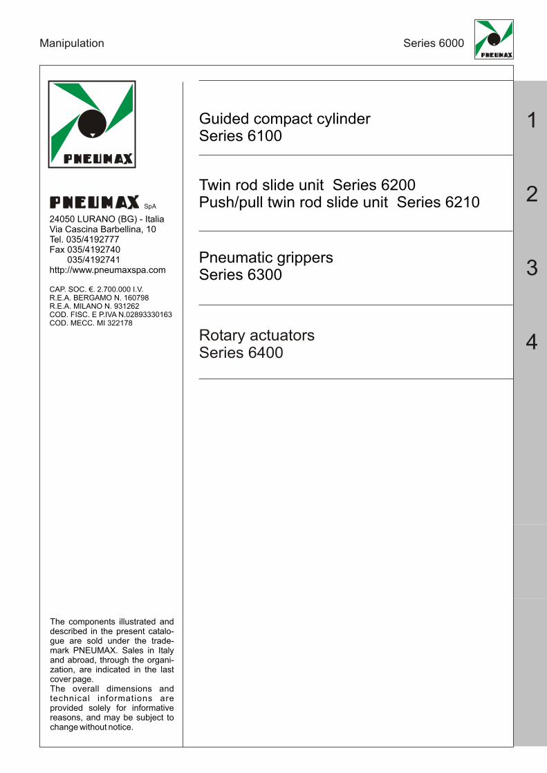
Manipulation Series 6000
Guided compact cylinderSeries 6100
Twin rod slide unit Series 6200Push/pull twin rod slide unit Series 6210
Pneumatic grippersSeries 6300
Rotary actuatorsSeries 6400
24050 LURANO (BG) - ItaliaVia Cascina Barbellina, 10 Tel. 035/4192777 Fax 035/4192740 035/4192741http://www.pneumaxspa.com
CAP. SOC. €. 2.700.000 I.V.R.E.A. BERGAMO N. 160798 R.E.A. MILANO N. 931262 COD. FISC. E P.IVA N.02893330163COD. MECC. MI 322178
SpA
The components illustrated and described in the present catalo-gue are sold under the trade-mark PNEUMAX. Sales in Italyand abroad, through the organi-zation, are indicated in the last cover page.The overall dimensions and technical informations are provided solely for informative reasons, and may be subject to change without notice.

111
Manipulation Series 6100
GUIDED COMPACT CYLINDERSeries 6100
General
Component description
Ordering Code, technical data
Dimension
Operating criteria
Magnetic sensors
1.0
1.1
1.2
1.3 - 1.4
1.5 - 1.9
1.10
Page

1
1.0
These guided compact cylinders, characterised by reduced overall dimensions, can be used for the compression, conveyance and manipulation of objects in many industrial sectors; similarly they can also be used in pushing, liftingand stopping applications.
These cylinders are available in sizes 32mm to 63 mm diameter, and comprise a single compact cylinder with integral guide rods, making it a true guide cylinder designed with installation flexibility and space saving at it's core.
The rod guide is available in two styles:Self lubricating bronze bushes, useful for absorbing lateral loads and forces, especially as a stopper.Bearing bushes, guaranteeing high precision and uniform movement with low friction characteristics, useful with misaligned loads.Guided compact cylinders are ideal for use in applications requiring a combination of reduced dimensions and anti-rotation features. Mounting can be achieved on three sides through holes or “T” slots.
Adjustable mounting holes in the front plate ensure safe and accurate assembly. Pneumatic connections can be made to either lateral or top ports, ( lateral ports plugged on standard units).When sensors are required, there are special slot in the barrel extrusion where 1580 series miniaturized sensors are easily fitted.
Guided compact cylinderGeneral Series 6100
Top mounting
Sensor slot
Sensor slot
“T” slot bottom mounting
Top Porting
Side porting(plugged)
Bottom mounting
Side mounting

Guided compact cylinderComponent description
Series 6100
1.1
Pos.123456789101112
Pos.131415161718192021
1
23
4
5
67
8
9
10
11
12
13
12
14
15 17
18
21
20
7
19
5
1110
16
ItemGuide rod screwPiston rod screwPlateRodCirclipPiston rod sealSealBushingPiston rodCushiuning washerPiston sealHalf piston
Qty.211221211222
ItemMagnetWiperBronze bushPiston rod nutBodyPlugEnd plateCirclipBearing bush
Qty.124*11212
4**
* N. 2 pieces for strokes under 50 mm (for bores ø20,25,32)** N. 2 pieces for strokes under 50 mm (for bores ø20,25,32)N. 2 pieces for strokes under 50 mm (for bores ø40,50,63)

1
Intermediate strokes are obtaining using spacers with defined length (5,10,15,20 mm).Example:It is possible obtaining a 6100.32.35B cylinder from a 6100.32.40B cylinder, inserting a spacer with length of 5 mm.
The strokes intermediate without using of spacers are considered special executions.
Guided compact cylinderOrdering code, technical data
Series 6100
1.2
Standard stroke
202532405063
B = Control unit with Bronze bushC = Control unit with Bearing bush
6100.Ø.stroke. _
BoreØ20Ø25Ø32Ø40Ø50Ø63
20 25 30 40 50 75 100 125 150 175 200
Construction characteristics
Technical characteristics
Ordering code
BodyGuide rods
PistonPiston rod
Rods bushingEnd platePiston sealPiston rod sealWipersPlate
Magnetic sensors: see page 1.10
oxidated aluminium alloyC43 chromed steel (control unit with Bronze bush)tempered and chromed steel (control unit with Bearing bush)aluminiumAISI303 chromed stainless steel (for bores ø20, ø25)C43 chromed steel (for bores ø32, ø40, ø50, ø63)bronze or bearing bushingoxidated aluminiumoil resistant NBR rubberself lubricating polyurethane compoundoil resistant NBR rubbernickel plated steel
FunctionFluidWorking pressureWorking temperature Cushioning
double acting
filtered and lubricated or non lubricated airmax. 10 bar-5°C ÷ +70°Celastic bumper on both ends

X
Guided compact cylinderOverall dimensions
Series 6100
1.3
Dimension of "T" slot
ØK
A(H
7)TD
TC TE
TATB
W (n.4 depth of thread WL)
ØKA (H7) (depth KD)
Detail X
V + Stroke
FB
Q V1
V2
K±0
.02
K
KB
KC
KD
F (n. 2 plugged connections)
FC
()
"T"s
lotf
orhe
xago
npi
n
B
D
Z (n°4 depthof thread ZL)
ØKA (H7)
(deptKD)
h
TE
K±0
.02
CA
X X
ØD
S
HA
ØD
A
Q V1
PA
DP
FA FP
SA
L + Stroke
L1 + Stroke
LT + Stroke
F (n. 2 connections)
G
P
ØUB (n. 4 counter bore depth UL)
ØUA (n. 4 through hole) ZS (n. 4 tapped through)
ØKA (H7)(depth KD)
K H
K±0
.02
N M

1
Series 6100Guided compact cylinderOverall dimensions
1.4
Stroke tolerance: +1.5mm
Bore stroke ≤ 30 30<stroke≤100 100<stroke≤200 stroke�≤�30 30<stroke≤100 100<stroke≤200
20 24 44 120 29 39 7725 24 44 120 29 39 77
stroke�≤�25 25<stroke≤100 100<stroke≤200 stroke�≤�25 25<stroke≤100 100<stroke≤200
32 24 48 124 33 45 8340 24 48 124 34 46 8450 24 48 124 36 48 8663 28 52 128 38 50 88
V1 V2
Control unit w ith bronze bushes
Bore stroke�≤�50 50<stroke≤200 stroke�≤�50 50<stroke≤200
20 53 84,5 12 0 31,525 53,5 85 16 0 31,532 97 102 20 37,5 42,540 97 102 20 31 3650 106,5 118 25 34,5 4663 106,5 118 25 29,5 41
LT SADA
Control unit w ith bearing bushes
Bore stroke�≤�30 30<stroke≤100 100<stroke≤200 stroke�≤�30 30<stroke≤100 100<stroke≤200
20 63 80 104 10 10 27 5125 69,5 85,5 104,5 14 16 32 51
stroke�≤�50 50<stroke≤100 100<stroke≤200 stroke�≤�50 50<stroke≤100 100<stroke≤200
32 81 98 118 16 21,5 38,5 58,540 81 98 118 16 15 32 5250 93 114 134 20 21 42 6263 93 114 134 20 16 37 57
DALT SA
Bore A B C D DP DS E F FA FB FC FP G H HA K KA KB KC KD L L1 M20 83 36 72 24 6 10 44 G1/8 10,5 10,5 10,5 8,5 18 54 25 28 3 3,5 3 6 37 53 8125 93 42 82 30 6 12 50 G1/8 11,5 11,5 13,5 9 26 64 28,5 34 4 4,5 3 6 37,5 53,5 9132 112 48 98 34 10 16 63 G1/8 12,5 12,5 15 9 30 78 34 42 4 4,5 3 6 37,5 59,5 11040 120 54 106 40 10 16 72 G1/8 14 14 18 10 30 86 38 50 4 4,5 3 6 44 66 11850 148 64 130 46 13 20 92 G1/4 14 12 21,5 11 40 110 47 66 5 6 4 8 44 72 14663 162 78 142 58 13 20 110 G1/4 16,5 16,5 28 13,5 50 124 55 80 5 6 4 8 49 77 158
Bore N PA P Q T TA TB TC TD TE UA UB UL V W WL Z ZL ZS20 70 10 30 17 M5 5,4 8,4 4,5 7,8 2,8 5,6 9,5 5,5 12,5 M6x1 12 M5x0,8 13 M5x0,825 78 10 38 17 M5 5,4 8,4 4,5 8,2 3 5,6 9,5 5,5 12,5 M6x1 12 M6x1 15 M6x132 96 12 44 21 M6 6,5 11 5,5 9,5 3,5 6,6 11 7,5 7 M8x1,25 16 M8x1,25 20 M8x1,2540 104 12 44 22 M6 6,5 11 5,5 11 4 6,6 11 7,5 13 M8x1,25 16 M8x1,25 20 M8x1,2550 130 15 60 24 M8 8,5 14 7,5 14 4,5 8,6 14 9 9 M10x1,5 20 M10x1,5 22 M10x1,563 130 15 70 24 M10 11 18 10 19 7 8,6 14 9 14 M10x1,5 20 M10x1,5 22 M10x1,5

Series 6100
1.5
Guided compact cylinderOperating criteria
Cylinder theoretic force
How to calculate the Momentum1__Ec = m V ²(J)2
BoreOut 314 63 94 126 157 188 220 251 283 314
In 236 47 71 94 118 142 165 189 212 236
Out 491 98 147 196 246 295 344 393 442 491
In 378 76 113 151 189 227 265 302 340 378
Out 804 161 241 322 402 482 563 643 724 804
In 603 121 181 241 302 362 422 482 543 603
Out 1257 251 377 503 629 754 880 1006 1131 1257
In 1056 211 317 422 528 634 739 845 950 1056
Out 1963 393 589 785 982 1178 1374 1570 1767 1963
In 1649 330 495 660 825 989 1154 1319 1484 1649
Out 3117 623 935 1247 1559 1870 2182 2494 2805 3117
In 2803 561 841 1121 1402 1682 1962 2242 2523 28032 3 4 5 6 7 8 9 10
Working pressure (bar)
Piston area (mm2)
Ø20
Ø25
Ø32
Force (N)
Ø40
Ø50
Ø63
Bore20 670 750 830 910 1170 1370 1570 1760 1960 216025 950 1050 1160 1270 1650 1920 2190 2470 2740 301032 1690 2070 2470 2850 3240 3620 4000 438040 1950 2370 2830 3250 3680 4100 4530 495050 3360 4000 4730 5370 6010 6650 7290 793063 4180 4940 5780 6540 7290 8050 8800 9560
20 330 350 380 400 520 580 640 700 760 82025 520 560 600 640 840 950 1050 1150 1250 135032 1070 1230 1420 1580 1740 1910 2070 223040 1140 1300 1490 1650 1810 1980 2140 230050 2150 2400 2750 3000 3260 3510 3760 402063 2500 2750 3090 3350 3600 3860 4110 4360
20 25 30 40 50 75 100 125 150 175 200
Weight of moving parts (gr)
Weight (gr)
Stroke
Bore20 700 770 890 970 1140 1310 1520 1690 1870 204025 980 1070 1250 1340 1570 1810 2080 2310 2540 277032 1540 1850 2300 2620 2990 3310 3620 394040 1790 2150 2640 3000 3420 3780 4140 450050 3110 3660 4410 4960 5600 6150 6700 725063 3930 4590 5460 6120 6880 7540 8210 8870
20 310 330 370 390 440 480 560 600 650 70025 490 520 580 610 690 760 880 950 1020 110032 820 940 1110 1230 1410 1530 1650 177040 890 1010 1180 1300 1480 1600 1720 183050 1770 1950 2240 2430 2710 2890 3080 327063 2110 2300 2590 2770 3050 3240 3420 3610
20 25 30 40 50 75 100 125 150 175 200
Weight of m oving parts (gr)
Stroke
W eight (gr)Control unit with bearing bushes
WeightsControl unit with bronze bushes
m = Total moving mass: weight of driven objectadded to weight of cylinder moving parts ( kg).V = max. speed: equal to average speed + 40% ( m/sec)
Maximum permissible Momentum(using this formula)
Boreø20ø25ø32ø40ø50ø63
Ec (J)0,10,20,30,50,91,55
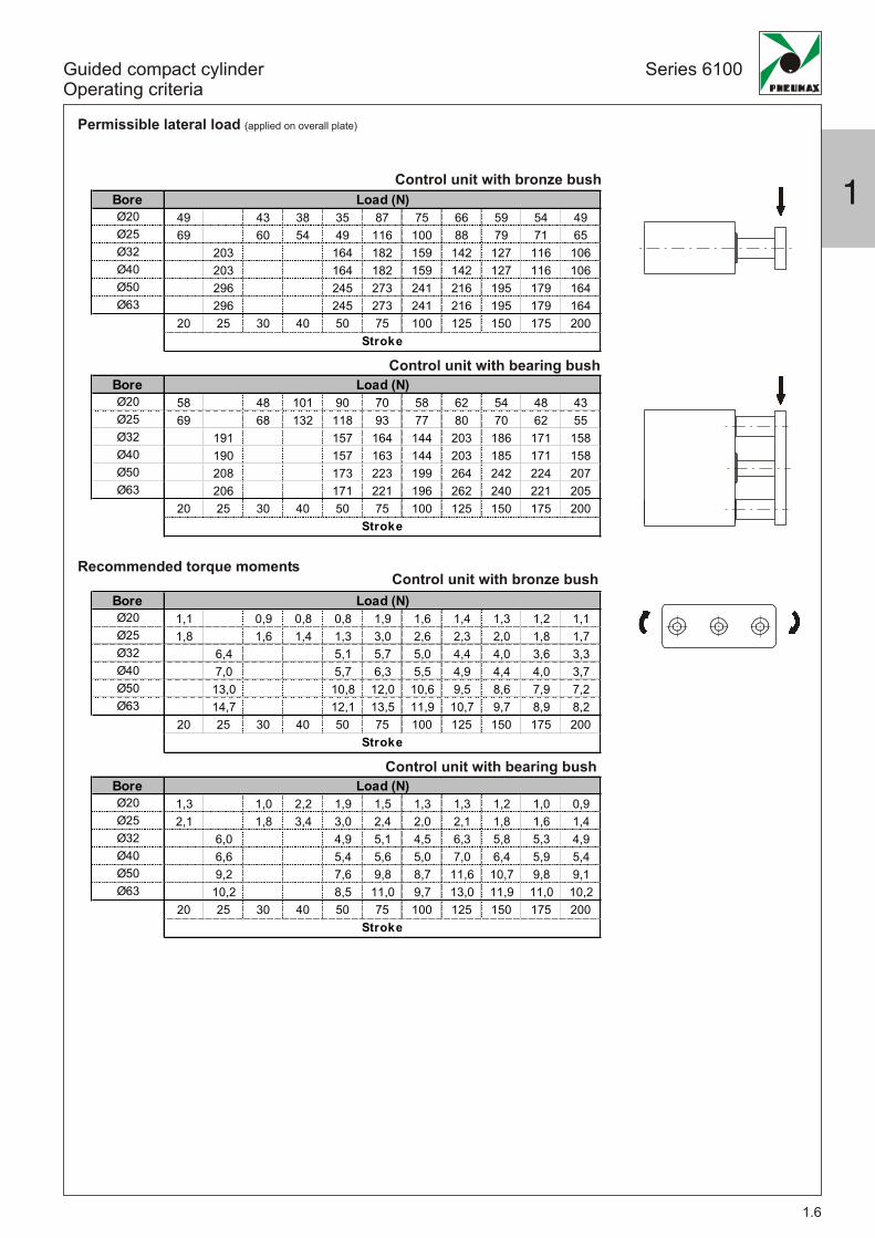
BoreØ20 49 43 38 35 87 75 66 59 54 49Ø25 69 60 54 49 116 100 88 79 71 65Ø32 203 164 182 159 142 127 116 106Ø40 203 164 182 159 142 127 116 106Ø50 296 245 273 241 216 195 179 164Ø63 296 245 273 241 216 195 179 164
20 25 30 40 50 75 100 125 150 175 200
BoreØ20 58 48 101 90 70 58 62 54 48 43Ø25 69 68 132 118 93 77 80 70 62 55Ø32 191 157 164 144 203 186 171 158Ø40 190 157 163 144 203 185 171 158Ø50 208 173 223 199 264 242 224 207Ø63 206 171 221 196 262 240 221 205
20 25 30 40 50 75 100 125 150 175 200
BoreØ20 1,1 0,9 0,8 0,8 1,9 1,6 1,4 1,3 1,2 1,1Ø25 1,8 1,6 1,4 1,3 3,0 2,6 2,3 2,0 1,8 1,7Ø32 6,4 5,1 5,7 5,0 4,4 4,0 3,6 3,3Ø40 7,0 5,7 6,3 5,5 4,9 4,4 4,0 3,7Ø50 13,0 10,8 12,0 10,6 9,5 8,6 7,9 7,2Ø63 14,7 12,1 13,5 11,9 10,7 9,7 8,9 8,2
20 25 30 40 50 75 100 125 150 175 200
BoreØ20 1,3 1,0 2,2 1,9 1,5 1,3 1,3 1,2 1,0 0,9Ø25 2,1 1,8 3,4 3,0 2,4 2,0 2,1 1,8 1,6 1,4Ø32 6,0 4,9 5,1 4,5 6,3 5,8 5,3 4,9Ø40 6,6 5,4 5,6 5,0 7,0 6,4 5,9 5,4Ø50 9,2 7,6 9,8 8,7 11,6 10,7 9,8 9,1Ø63 10,2 8,5 11,0 9,7 13,0 11,9 11,0 10,2
20 25 30 40 50 75 100 125 150 175 200
Load (N)
Stroke
Load (N)
Stroke
Load (N)
Stroke
Load (N)
Stroke
Series 6100
1.6
Guided compact cylinderOperating criteria
Permissible lateral load (applied on overall plate)
Recommended torque moments
Control unit with bearing bush
Control unit with bearing bush
Control unit with bronze bush
Control unit with bronze bush
1

Series 6100
1.7
Guided compact cylinderOperating criteria
Stopper device applications
Control unit with bronze bushes
ATTENTION: if H>50 mm use larger bore
H=5
0mm
H=5
0mm
Load LoadM
ovin
glo
ad(N
)
ATTENTION: use with stroke ≤ 30 mm
Load speed (mm/sec)Ø20 - Ø25
ATTENTION: use with stroke ≤ 50 mm
Ø20 - Ø25
Ø32 - Ø40 - Ø50 - Ø63Load speed (mm/sec)
Mov
ing
load
(N)

Series 6100
1.8
Guided compact cylinderOperating criteria
Control unit with bronze bushes
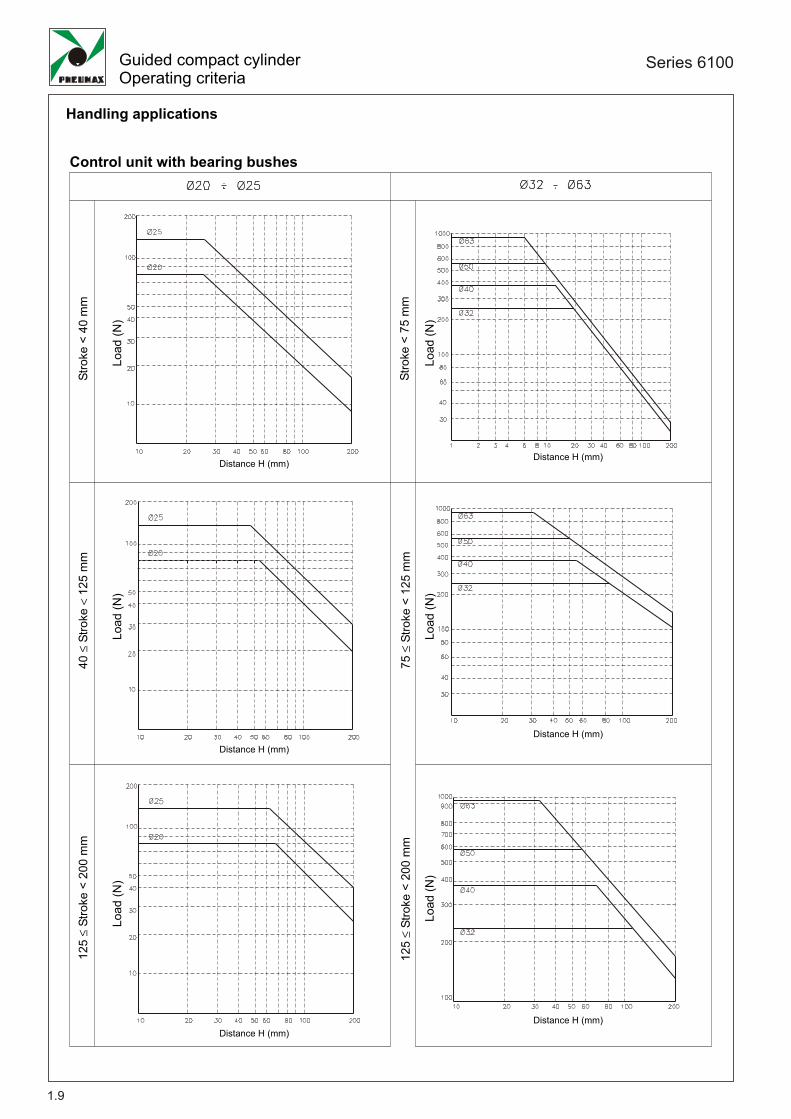
Handling applications
Working conditionswith 5 bar pressure
H H
Load Load
Load
(N)
Distance H (mm)
Stro
ke<
75m
m
Distance H (mm)
Load
(N)
75≤
Stro
ke<
200
mm
1
Series 6100
1.9
Handling applications
Control unit with bearing bushes
Guided compact cylinderOperating criteria
40≤
Stro
ke<
125
mm
Distance H (mm)
Load
(N)
Load
(N)
Stro
ke<
75m
m
Load
(N)
Stro
ke<
40m
m
Distance H (mm)Distance H (mm)
Distance H (mm)
Load
(N)
125
≤St
roke
<20
0m
m
Distance H (mm)
125
≤St
roke
<20
0m
m
Load
(N)
Distance H (mm)
Load
(N)
75≤
Stro
ke<
125
mm

Series 6100
1.10
Guided compact cylinderMagnetic sensor
Sensor c/w 2,5 m. cable
Sensor c/w M8 connector (300 mm cable)
Technical characteristics
1580.U1580.HAPMRS.UMHS.PMC1MC2MCH1MCH2
Reed bulb sensor with led and 2.5 m cablePNP sensor Hall effect with led and 2.5 m cableReed bulb sensor with led and connectorPNP sensor Hall effect with led and connectorM8 in line connector with 2.5 m cable (2 wires)M8 in line connector with 5 m cable (2 wires)M8 in line connector with 2.5 m cable (3 wires)M8 in line connector with 5 m cable (3 wires)
Ordering codes
NOTE: Pay attention to the connected loads which should not exceed recommendations*Reed bulb sensor: connection can be made either to negative or positive pole
Type of contactMaximum current (pulses of 0.5 sec)Maximum permanent currentMaximum permanent powerVoltage range A.C.Voltage range D.C.Working temperatureMaximum voltage dropCable sectionDegree of protectionConnecting timeDisconnecting timeAverage life (operations)Repetition of intervention point
6VA3 ÷ 30V3 ÷ 30V
4W/
12 ÷ 30V
3V
N.A.
IP 65
± 0,1
2x0,14
0,5 ms0,1 ms
710
3x0,14
0,8 μs0,3 μs
910
-20° C ÷ 70°C
0,1A0,1A
0,2A0,2A
1580.U 1580.HAPMRS.U MHS.P
Diagrams andconnection
With Reed bulb
Hall effect
Weight gr. 27
Weight gr. 15
6,5 5
32
4,3
3
30
M8x
1
32 300 mm
bn
bl
LOA
D
blue
brownbrown
black
*LOAD*LOAD
1

Manipulation Series 6200
2PNEUMATIC SLIDE UNITS
Twin rod slide units
Push/pull twin rod slide units
Component descriptions
Component descriptions
Ordering codes, technical data
Overall dimensions Ø10 - Ø15
Overall dimensions Ø20 - Ø25 - Ø32
Operating conditions
6200B series
6200C series
Component descriptions Ø10
Component descriptions Ø15 - Ø25
Ordering codes, technical data
Overall dimensions
Operating conditions
Magnetic sensors
2.8
2.9
2.10
2.11-2.13
2.14-2.15
2.16
Page
2.1
2.2
2.3
2.4
2.5
2.6 - 2.7
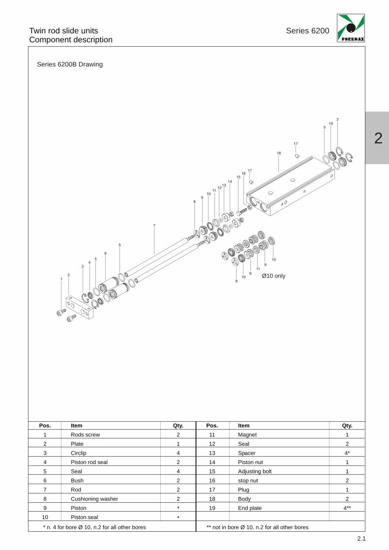
Twin rod slide unitsComponent description
Series 6200
12
3
3
45
5
5
6
7
8
8
9
9
9
10
10 Ø10 only
10
11
11
1213
14
1516
17
17
19
18
Pos.123456789
10
Pos.111213141516171819
ItemRods screwPlateCirclipPiston rod sealSealBushRodCushioning washerPistonPiston seal
Qty.21424222**
ItemMagnetSealSpacerPiston nutAdjusting boltstop nutPlugBodyEnd plate
Qty.124*11212
4**
** not in bore Ø 10, n.2 for all other bores* n. 4 for bore Ø 10, n.2 for all other bores
2.1
2
Series 6200B Drawing

10 15 20 25 30 35 40 45 50 60 70 75 80 90 100Ø10 • • • • • • • • • • • •Ø15 • • • • • • • • • • • • • • •Ø20 • • • • • • • • • • • • • • •Ø25 • • • • • • • • • • • • • • •Ø32 • • • • • • • • • • • • • • •
Stroke (mm)Bore
Twin rod slide unitsOrdering codes, technical data
Series 6200
2.2
Standard strokes
1015202532
B = Control unit with bronze bushC = Control unit with bearing bush
6200.Ø.stroke. _
Construction characteristics
Technical characteristics
Ordering code
Magnetic sensors: see page.2.13
oxidated aluminium alloyC43 chromed steel (control unit with Bronze bush)tempered and chromed steel (control unit with Bearing bush)aluminiumbrassoxidated aluminiumoil resistant NBR rubberself lubricating polyurethane compoundoxidated aluminium
BodyRods
PistonRod bushingEnd platePiston sealPiston rod sealPlate
FunctionFluidMax. pressureWorking temperatureCushioning
double actingfiltered and lubricated or non lubricated air7 bar-5°C ÷ +70°Celastic bumper
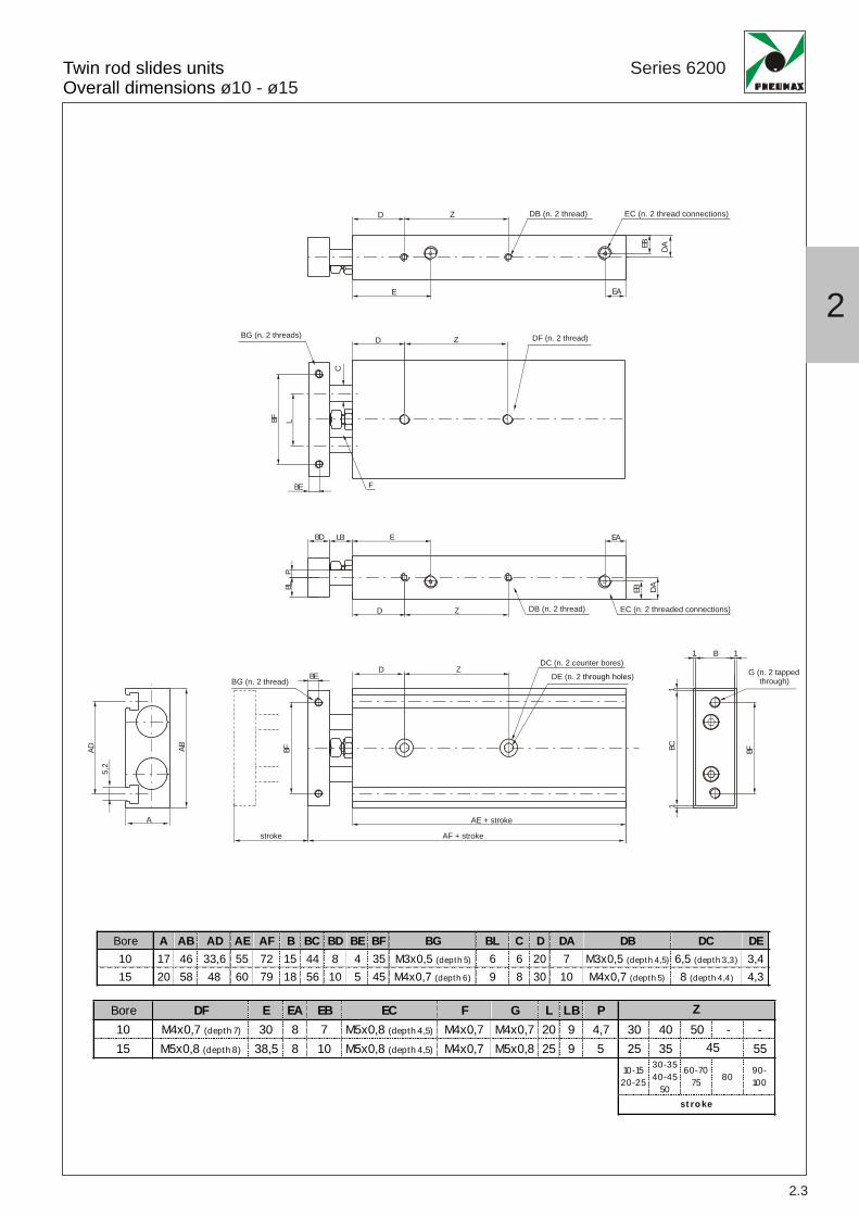
Bore DF E EA EB EC F G L LB P10 M4x0,7 (depth 7) 30 8 7 M5x0,8 (depth 4,5) M4x0,7 M4x0,7 20 9 4,7 30 40 50 - -15 M5x0,8 (depth 8) 38,5 8 10 M5x0,8 (depth 4,5) M4x0,7 M5x0,8 25 9 5 25 35 55
10-1520-25
30-3540-45
50
60-7075 80
90-100
Z
45
st roke
Bore A AB AD AE AF B BC BD BE BF BG BL C D DA DB DC DE10 17 46 33,6 55 72 15 44 8 4 35 M3x0,5 (depth 5) 6 6 20 7 M3x0,5 (depth 4,5) 6,5 (depth 3,3) 3,415 20 58 48 60 79 18 56 10 5 45 M4x0,7 (depth 6) 9 8 30 10 M4x0,7 (depth 5) 8 (depth 4,4) 4,3
Twin rod slides unitsOverall dimensions ø10 - ø15
Series 6200
2.3
D
EB DA
E
BD
BL EB DA
P
D
5,2
Z DB (n. 2 thread) EC (n. 2 threaded connections)
LB E EA
EA
DB (n. 2 thread) EC (n. 2 thread connections)
BF BC1
1 1
1
BFAD AB
DBEBG (n. 2 thread)
Z
AE + stroke
AF + strokestroke
DC (n. 2 counter bores)DE (n. 2 )through holes
A
G (n. 2 tapped through)
B
Z
DBG (n. 2 threads)
BE F
BF
C
L
Z DF (n. 2 thread)
2

2.4
Bore DF DG DH E EA EB EC F G L LB P20 M6x1 (depth 10) 7,75 9,5 45 8 7,8 M5x0,8 (depth 4,5) M6x1 M5x0,8 28 12 6,3 30 4025 M8x1,25 (depth 12) 8,5 13 46 9 15 G1/8 (depth 6,5) M6x1 M6x1 35 12 8,3 30 4032 M8x1,25 (depth 12) 9 20 56 10 19 G1/8 (depth 6,5) M8x1,25 M6x1 44 14 12 40 50
10-1520-25
30-3540-45
50
60-7075
80 90-100
70
st ro ke
6060
Z
Bore A AB AD AE AF B BC BD BE BF BG BL C D DA DB DC DE20 25 64 53 70 94 23 62 12 6 50 M4x0,7 (depth 6) 11,5 10 30 12,5 M4x0,7 (depth 6) 9,5 (depth 5,3) 5,525 30 80 64 72 96 28 78 12 6 60 M5x0,8 (depth 7,5) 14 12 30 15 M5x0,8 (depth 7,5) 11 (depth 6,3) 6,932 38 98 76 82 112 36 96 16 8 75 M5x0,8 (depth 8) 18 16 30 19 M5x0,8 (depth 7,5) 11 (depth 6,3) 6,9
Twin rod slides unitsOperating instructions ø20 - ø25 - ø32
Series 6200
D
DHDG EB
DA
E EA
DB (n. 4 threads) EC (n. 2 threaded connections)Z
Z DF (n. 2 threads)
FBE
BF L
BG (n. 2 threads) D
C
EBDGDH
DA
DB (n. 4 thread)
EC (n. 2 thread connections)
EABD LB E
D Z
BLP
G (n. 2 tapped through)
1 1
BC1
1
BF
B
DC (n. 2 counter bores)
DE (n. 2 through holes)
AE + stroke
AF + stroke
A
stroke
DBE
BFABAD
5,2
BG (n. 2 thread) Z
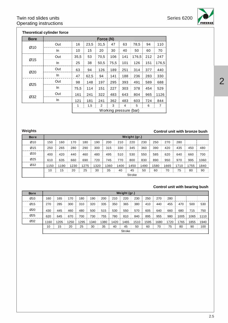
BoreOut 16 23,5 31,5 47 63 78,5 94 110In 10 15 20 30 40 50 60 70
Out 35,5 53 70,5 106 141 176,5 212 247In 25 38 50,5 75,5 101 126 151 176,5
Out 63 94 126 189 251 314 377 440In 47 62,5 94 141 188 236 283 330
Out 98 148 197 295 393 491 589 688In 75,5 114 151 227 303 378 454 529
Out 161 241 322 483 643 804 965 1126In 121 181 241 362 483 603 724 844
1 1,5 2 3 4 5 6 7
Force (N)
Working pressure (bar)
Ø10
Ø15
Ø20
Ø25
Ø32
2.5
Twin rod slides unitsOperating instructions
Series 6200
Theoretical cylinder force
Control unit with bearing bush
Weights Control unit with bronze bushBoreØ10 150 160 170 180 190 200 210 220 230 250 270 280
Ø15 250 265 280 290 300 315 330 345 360 390 420 435 450 480
Ø20 400 420 440 460 480 495 510 530 550 585 620 640 660 700Ø25 610 635 660 690 720 745 770 800 830 890 950 970 995 1060Ø32 1150 1190 1230 1275 1320 1360 1400 1450 1490 1580 1665 1710 1755 1840
10 15 20 25 30 35 40 45 50 60 70 75 80 90Stroke
Weight (gr.)
BoreØ10 160 165 170 180 190 200 210 220 230 250 270 280
Ø15 270 285 300 310 320 335 350 365 380 410 440 455 470 500 530
Ø20 430 445 460 480 500 515 530 550 570 605 640 660 680 715 750Ø25 620 645 670 700 730 755 780 810 840 895 955 980 1005 1065 1110Ø32 1160 1205 1250 1295 1340 1380 1420 1465 1510 1595 1680 1720 1765 1855 1940
10 15 20 25 30 35 40 45 50 60 70 75 80 90 100
Weight (gr.)
Stroke
Force (N)
2

2.6
Twin rod slides unitsOperating instructions
Series 6200
Control unit with bearing bushControl unit with bronze bush
Force
Force
Permissible loads
Stroke (mm)
Load
(N)
Stroke (mm)
Load
(N)
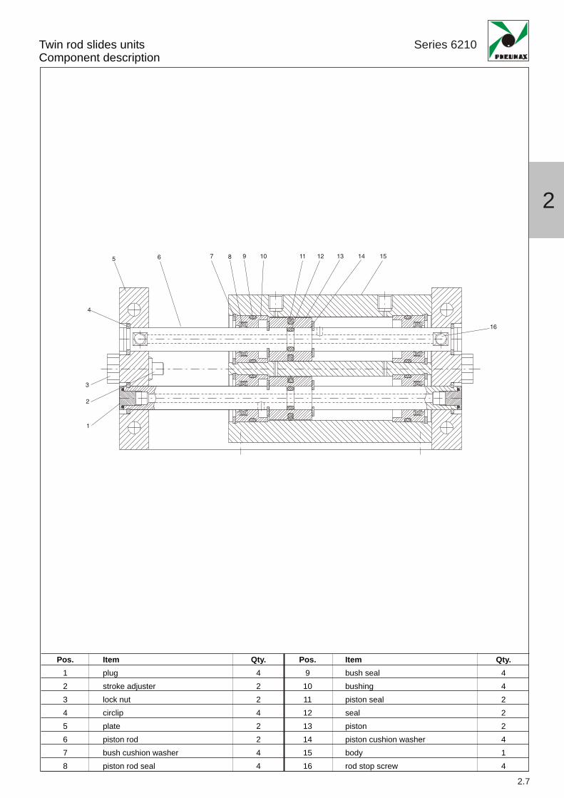
Twin rod slides unitsComponent description
Series 6210
2.7
1
2
3
4
5 6 7 8 9 10 11 12 13 14 15
16
2
Pos.12345678
Pos.9
10111213141516
Itemplugstroke adjusterlock nutcirclipplatepiston rodbush cushion washerpiston rod seal
Qty.42242244
Itembush sealbushingpiston sealsealpistonpiston cushion washerbodyrod stop screw
Qty.44222414
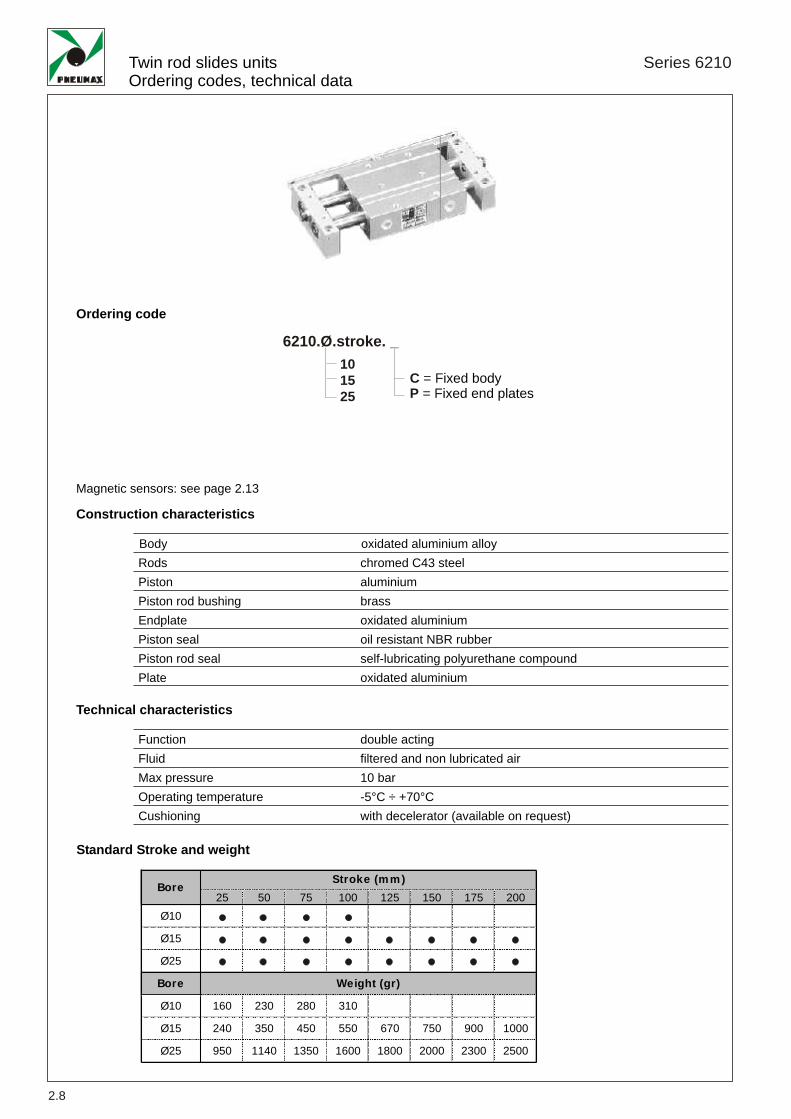
Twin rod slides unitsOrdering codes, technical data
Series 6210
2.8
Standard Stroke and weight
101525
C = FP = F
ixed bodyixed end plates
6210.Ø.stroke. _
Construction characteristics
Ordering code
Magnetic sensors: see page 2.13
BodyRodsPistonPiston rod bushingEndplatePiston sealPiston rod sealPlate
25 50 75 100 125 150 175 200Ø10 • • • •
Ø15 • • • • • • • •
Ø25 • • • • • • • •
Bore
Ø10 160 230 280 310
Ø15 240 350 450 550 670 750 900 1000
Ø25 950 1140 1350 1600 1800 2000 2300 2500
Weight (gr)
Stroke (mm)Bore
oxidated aluminium alloychromed C43 steelaluminiumbrassoxidated aluminiumoil resistant NBR rubberself-lubricating polyurethane compoundoxidated aluminium
Technical characteristics
FunctionFluidMax pressureOperating temperatureCushioning
double actingfiltered and non lubricated air10 bar-5°C ÷ +70°Cwith decelerator (available on request)
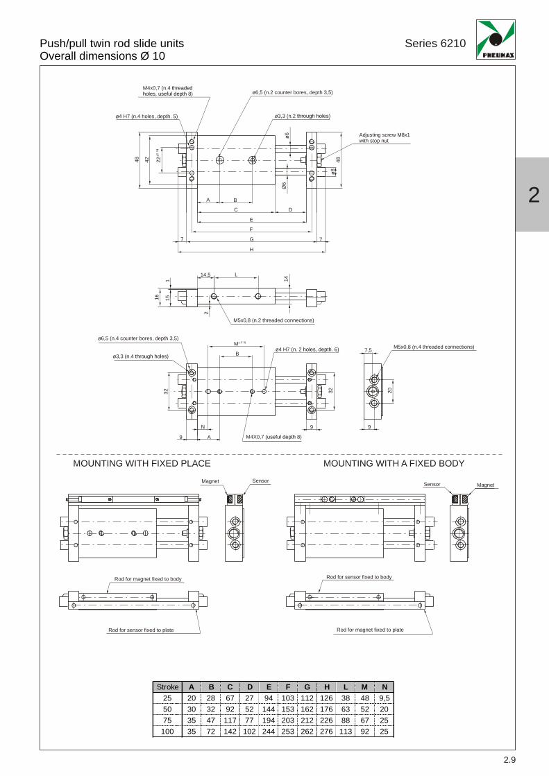
Stroke A B C D E F G H L M N25 20 28 67 27 94 103 112 126 38 48 9,550 30 32 92 52 144 153 162 176 63 52 2075 35 47 117 77 194 203 212 226 88 67 25
100 35 72 142 102 244 253 262 276 113 92 25
48 48ø8
42 22
7 7
Ø6
ø6
A B
C
E
F
G
H
M
N 99
9 A
7,5B
L14,5
141
16 1532 2032
2D
ø4 H7 (n.4 holes, depth. 5)
M4X0,7 ( 8)useful depth
ø4 H7 (n. 2 . 6)holes, depth
MOUNTING WITH FIXED PLACE MOUNTING WITH A FIXED BODY
ø3,3 (n.2 )through holes
Adjusting screw M8x1 with stop nut
ø3,3 (n.4 )through holes
ø6,5 (n.2 counter bores, depth 3,5)
ø6,5 (n.4 counter bores, depth 3,5)
M4x0,7 (n.4 8)
threadedholes, useful depth
M5x0,8 (n.2 threaded connections)
M5x0,8 (n.4 threaded connections)
Magnet
Rod for magnet fixed to body
Rod for magnet fixed to plate
Rod for sensor fixed to body
Rod for sensor fixed to plate
MagnetSensor Sensor
Push/pull twin rod slide unitsOverall dimensions Ø 10
Series 6210
2.9
2
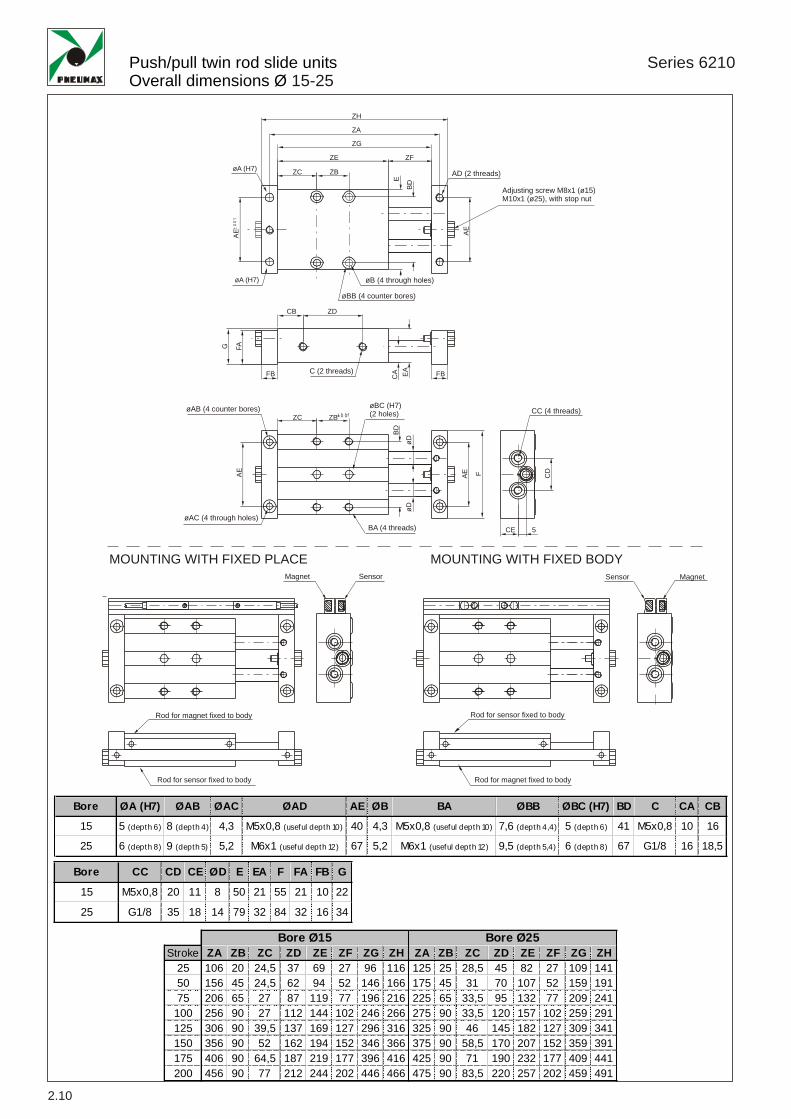
Push/pull twin rod slide unitsOverall dimensions Ø 15-25
Series 6210
2.10
øBC (H7)(2 holes)
C (2 threads)
CC (4 threads)
BA (4 threads)
Magnet
Rod for magnet fixed to body
Rod for magnet fixed to body
Rod for sensor fixed to body
Rod for sensor fixed to body
MagnetSensor Sensor
øB (4 through holes)
øAC (4 through holes)
øBB (4 counter bores)
øAB (4 counter bores)
AD (2 threads)
Bore CC CD CE ØD E EA F FA FB G
15 M5x0,8 20 11 8 50 21 55 21 10 22
25 G1/8 35 18 14 79 32 84 32 16 34
Bore ØA (H7) ØAB ØAC ØAD AE ØB BA ØBB ØBC (H7) BD C CA CB
15 5 (depth 6) 8 (depth 4) 4,3 M5x0,8 (useful depth 10) 40 4,3 M5x0,8 (useful depth 10) 7,6 (depth 4,4) 5 (depth 6) 41 M5x0,8 10 16
25 6 (depth 8) 9 (depth 5) 5,2 M6x1 (useful depth 12) 67 5,2 M6x1 (useful depth 12) 9,5 (depth 5,4) 6 (depth 8) 67 G1/8 16 18,5
Stroke ZA ZB ZC ZD ZE ZF ZG ZH ZA ZB ZC ZD ZE ZF ZG ZH25 106 20 24,5 37 69 27 96 116 125 25 28,5 45 82 27 109 14150 156 45 24,5 62 94 52 146 166 175 45 31 70 107 52 159 19175 206 65 27 87 119 77 196 216 225 65 33,5 95 132 77 209 241
100 256 90 27 112 144 102 246 266 275 90 33,5 120 157 102 259 291125 306 90 39,5 137 169 127 296 316 325 90 46 145 182 127 309 341150 356 90 52 162 194 152 346 366 375 90 58,5 170 207 152 359 391175 406 90 64,5 187 219 177 396 416 425 90 71 190 232 177 409 441200 456 90 77 212 244 202 446 466 475 90 83,5 220 257 202 459 491
Bore Ø15 Bore Ø25
ZCøA (H7)
øA (H7)
ZB
E
BD
AEFA
BD
øDøD
AE AE CDF
G
EACA
AE
ZE
ZG
ZA
ZH
ZF
CB ZD
FB
CE 5
ZC ZB
FB
Adjusting screw M8x1 (ø15)M10x1 (ø25), with stop nut
MOUNTING WITH FIXED PLACE MOUNTING WITH FIXED BODY

2.11
Theoretical force
Deflection of piston rods
Applied load to body centre
Applied load to plate centre
Bore Load (N)10 10 0,07 /15 30 0,08 0,2825 60 0,02 0,08
100 200Stroke
Deflection (mm)
Bore Load (N)10 3 0,06 0,3 / /15 5 0,1 0,2 0,5 125 10 0,03 0,1 0,15 0,25
50 100 150 200Stroke
Deflection (mm)
Bore Effective area (mm2)
10 101 20 30 40 51 61 71 81 91
15 207 41 62 83 104 124 145 166 186
25 597 119 179 239 299 358 418 478 5372 3 4 5 6 7 8 9
Working pressure (bar)
Force (N)
2
Push/pull twin rod slide unitsOperating conditions
Series 6210

Push/pull twin rod slide unitsOperating conditions
Series 6210
2.12
Control unit with bearing bushesControl unit with bronze bushes
Load
Load
Load
(N)
Distance H (mm)
Load
(N)
Distance H (mm)

Push/pull twin rod slide unitsMagnetic sensor
Series 6210
2
2.13
1580.U1580.HAPMRS.UMHS.PMC1MC2MCH1MCH2
Reed bulb sensor with led and 2.5 m cablePNP sensor Hall effect with led and 2.5 m cableReed bulb sensor with led and connectorPNP sensor Hall effect with led and connectorM8 in line connector with 2.5 m cable (2 wires)M8 in line connector with 5 m cable (2 wires)M8 in line connector with 2.5 m cable (3 wires)M8 in line connector with 5 m cable (3 wires)
Sensor c/w 2,5 m. cable
Sensor c/w M8 connector (300 mm cable)
Ordering codes
Type of contactMaximum current (pulses of 0.5 sec)Maximum permanent currentMaximum permanent powerVoltage range A.C.Voltage range D.C.Working temperatureMaximum voltage dropCable sectionDegree of protectionConnecting timeDisconnecting timeAverage life (operations)Repetition of intervention point
Technical characteristics
6VA3 ÷ 30V3 ÷ 30V
4W/
12 ÷ 30V
3V
N.A.
IP 65
± 0,1
2x0,14
0,5 ms0,1 ms
710
3x0,14
0,8 μs0,3 μs
910
-20° C ÷ 70°C
0,1A0,1A
0,2A0,2A
1580.U 1580.HAP
NOTE: Pay attention to the connected loads which should not exceed recommendations
*Reed bulb sensor: connection can be made either to negative or positive pole
MRS.U MHS.P
Diagrams andconnection
With Reed bulb
Hall effect
Weight gr. 27
Weight gr. 15
6,5 5
29
4,3
3
26,5
M8x
1
29 300 mm
bn
bl
LOAD
blue
brownbrown
black
*LOAD*LOAD

Manipulation Series 6300
PNEUMATIC GRIPPERS
Angular grippers
Parallel style grippers
Standard version - series 6301
180° Angular gripper - series 6302
Standard version - series 6310
Wide opening - series 6311
3.1
3.7
Page
180° angular gripper, rack pinion style series 6303
3.13
3
3.19
3.25
3 fingers parallel style ( air chuck)series 6312
Magnetic sensor
3.31
3.39
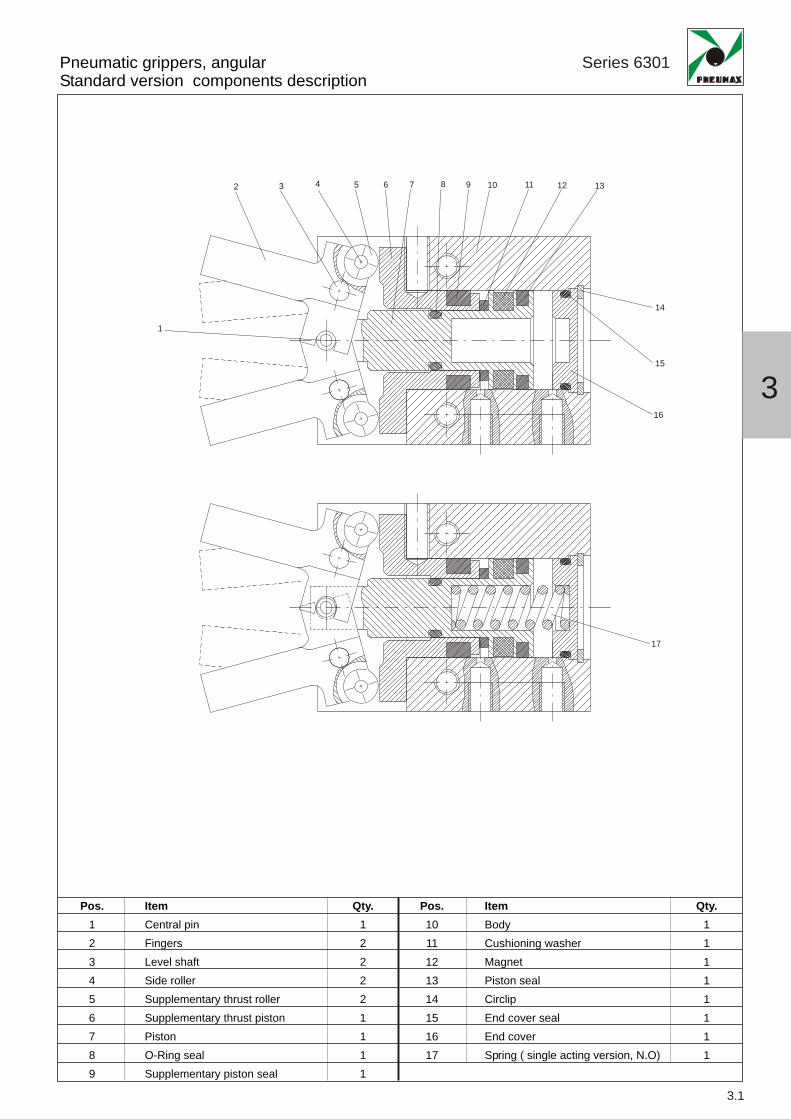
Pneumatic grippers, angularStandard version components description
Series 6301
3.1
1
2 3 4 5 6 7 8 9 10 11 12 13
14
15
16
17
3
Pos.123456789
Pos.1011121314151617
ItemCentral pinFingersLevel shaftSide rollerSupplementary thrust rollerSupplementary thrust pistonPistonO-Ring sealSupplementary piston seal
Qty.122221111
ItemBodyCushioning washerMagnetPiston sealCirclipEnd cover sealEnd coverSpring ( single acting version, N.O)
Qty.11111111

Pneumatic grippers, angularStandard version - ordering codes and technical data
Series 6301
3.2
D = DS = S
ouble actingingle acting ( N.O)
6301.Ø. _
Construction characteristics
Ordering code
BodyPistonFingersEnd coverSeals
oxidated aluminiumoxidated aluminiumnitrate steeloxidate aluminiumoil resistant NBR rubber
Bore
10
16
20
25
-10° ÷ 30°
Opening totalstroke
10162025
Magnetic sensors : see page 3.38
Holding force (Nm) at 5 bar
Technical characteristics
FluidWorking pressure
Operating temperature
filtered and lubricated or non lubricated air1 ÷ 6 bar for double acting2,5 ÷ 6 bar for single acting-5°C ÷ +70°C
Double acting
0,1
0,4
0,7
1,35
Single acting
0,07
0,30
0,55
1,08

Pneumatic grippers, angularStandard version - Overall dimensions
3.3
AC
AB
DE DBD
CEB
GL
FA
PA
LB DA
G
GAGCD
GG
D
30°O
peni
ng
10°C
losi
ngGB
LA
GH
FC
FB
EALC
D (2 threads)
E (2 threads)
A (2 threads)
DF (2 through holes)
F (connection for gripping)C (4 threads)
F (connection for opening)
øM H9 (useful depth 1,5)
Bore A AB AC C D DA DB DC DE DF E EA EB10 M3x0,5 (useful depth 6) 11,6 11,4 M2,5x0,45 M3x0,5 (useful depth 5) 16 12,8 10 2,8 2,6 M3x0,5 (useful depth 6) 12 1816 M4x0,7 (useful depth 6,5) 14,6 16 M3x0,5 M4x0,7 (useful depth 8) 24 16,2 16 3,9 3,4 M4x0,7 (useful depth 8) 15 2220 M5x0,8 (useful depth 8) 20,2 18,6 M4x0,7 M5x0,8 (useful depth 10) 30 21,7 20 4,5 4,3 M5x0,8 (useful depth 10) 18 3225 M6 (useful depth 10) 23,9 22 M5x0,8 M6 (useful depth 12) 36 25,8 25 4,6 5,1 M6 (useful depth 12) 22 40
Bore F FA FB FC G GA GB GC GD GH GL LA LB LC M PA Weight (gr.)10 M3x0,5 10,4 7,2 18,8 17,2 12 5,7 3 2 52,4 6,4 0/-0,1 38,6 23 16,4 11 H9 5,4 4016 M5x0,8 13 7 18,3 22,6 16 7 4 3,5 62,5 8 0/-0,1 44,6 30,6 23,6 17 H9 5,8 9020 M5x0,8 15 7,5 22,2 28 20 9 5,2 4 78,7 10 0/-0,1 55,2 42 27,6 21 H9 9 18025 M5x0,8 20 7,7 23,5 37,5 27 12 8 5 92 12 0/-0,1 60,4 52 33,6 26 H9 11,5 315
3
Series 6301
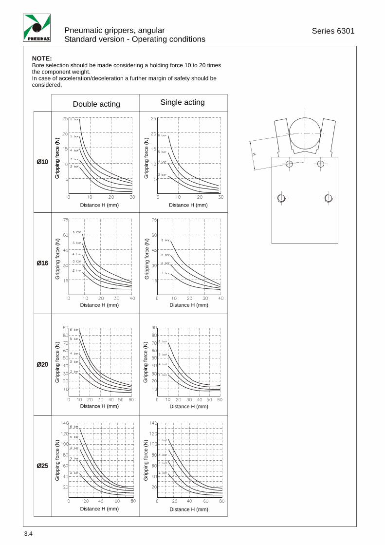
Pneumatic grippers, angularStandard version - Operating conditions
Series 6301
3.4
H
NOTE:Bore selection should be made considering a holding force 10 to 20 timesthe component weight.In case of acceleration/deceleration a further margin of safety should beconsidered.
Ø10Ø10
Ø16Ø16
Ø20Ø20
Ø25Ø25
Distance H (mm)
Double acting Single acting
Distance H (mm)
Grip
ping
forc
e(N
)G
rippi
ngfo
rce
(N)
Distance H (mm) Distance H (mm)
Grip
ping
forc
e(N
)G
rippi
ngfo
rce
(N)
Distance H (mm) Distance H (mm)
Distance H (mm)Distance H (mm)
Grip
ping
forc
e(N
)G
rippi
ngfo
rce
(N)
Grip
ping
forc
e(N
)
Grip
ping
forc
e(N
)
Grip
ping
forc
e(N
)

3.5
3

3.6

Pneumatic grippers, 180 °angularComponent description
Series 6302
1 2 3 4 5 6 7 8 9 10 11 12
13
14
15
1617
3.7
Pos.123456789
Pos.1011121314151617
ItemFingersClosing plateBearingPinThrust leverThrust pinRod sealBodyRod
Qty.212212111
ItemCushioningMagnetPiston sealSliding blockEnd coverCirclipEnd cover sealPiston
Qty.11111111
3
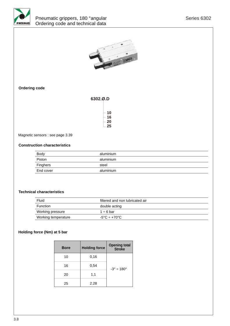
Pneumatic grippers, 180 °angularOrdering code and technical data
Series 6302
3.8
Holding force (Nm) at 5 bar
6302.Ø.D
Construction characteristics
Technical characteristics
Ordering code
BodyPistonFinghersEnd cover
FluidFunctionWorking pressureWorking temperature
Opening totalStroke
10162025
Magnetic sensors : see page 3.39
aluminiumaluminiumsteelaluminium
Bore
10
16
20
25
Holding force
0,16
0,54
1,1
2.28
-3° ÷ 180°
filtered and non lubricated airdouble acting1 ÷ 6 bar-5°C ÷ +70°C

3
Pneumatic grippers, 180 °angularOverall dimensions
Series 6302
3.9
ACD
A
GB
GC
GLD
CLB EB
GG
AB
E (2 threads)
DB
DD
EA DE
LA
FC
FA
PA3 ø4
NA
N
NBP
FB
LC
D (2 threads)
øDF (2 through holes) C (4 threads)
GD
A (2 threads)
F (connection for closing)
F (connection for opening)Back view detail
øM (useful depth 1,5)
Bore F FA FB FC G GB GC GD GL LA LB LC N NA ØM (H9) ØNB (H ) P PA Weight (gr.)10 M5x0,8 3 7 23 23,5 6 3 4 6 58 30 15 4 9 11 3 (useful depth 3) 2 13 7016 M5x0,8 8 7 25 28,5 7 4 5 8 69 38 20 4 15 17 3 (useful depth 3) 2,5 18 15020 M5x0,8 2 8 32 37 9 5 8 10 86 48 26 5 19 21 4 (useful depth 4) 3 20 32025 M5x0,8 14 8 42 45 12 6 10 12 107 58 30 5 23 26 4 (useful depth 4) 3 24 550
Bore A AB AC C D DA DB DC DD DE DF E EA EB10 M3x0,5 (useful depth 4) 30 9 M3x0,5 M3x0,5 (useful depth 6) 24 18 22 35 47,5 3,4 M3x0,5 (useful depth 6) 9 2416 M4x0,7 (useful depth 5) 33 12 M3x0,5 M4x0,7 (useful depth 8) 30 20 28 41 55,5 4,5 M4x0,7 (useful depth 8) 12 3020 M5x0,8 (useful depth 8) 42 14 M4x0,7 M5x0,8 (useful depth 10) 36 25 36 51 69 5,5 M5x0,8 (useful depth 10) 16 3825 M6x1 (useful depth 10) 50 16 M5x0,8 M6x1 (useful depth 12) 42 30 45 60 86 6,6 M6x1 (useful depth 12) 18 46
-0.005-0.025

Pneumatic grippers, 180 °angularOperating conditions
Series 6302
3.10
Ø10 Ø16
Ø20 Ø25
H
Grip
ping
forc
e(N
)
Distance H (mm)
Pressure (bar)
Dis
tanc
eH
(mm
)
Grip
ping
forc
e(N
)
Grip
ping
forc
e(N
)G
rippi
ngfo
rce
(N)
Distance H (mm)
Distance H (mm)Distance H (mm)
Distance H (mm)

3
3.11

3.12
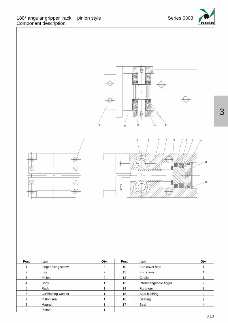
180° angular gripper rack pinion styleComponent description
Series 6303
3.13
1 2 3 4 5 6 7 8 9 10
11
12
13 14 15 16 17
3
Pos.123456789
Pos.1011121314151617
ItemFinger fixing screw
eyPinionBodyRackCushioning washerPiston sealMagnetPiston
Qty.822111111
ItemEnd cover sealEnd coverCirclipInterchangeable tingerFix tingerSeal bushingBearingSeal
Qty.11122224

180° angular gripper rack pinion styleOrdering code and technical data
Series 6303
3.14
Construction characteristics
Technical characteristics
Ordering code
Magnetic sensors : see page 3.38
6303.Ø.D._
202532
050
F = Fingers, end fixingL = Fingers, side fixing
BodyPistonFinghersEnd cover
aluminiumsteelsteelaluminium
FluidFunctionWorking pressureWorking temperature
filtered and non lubricated airdouble acting1 ÷ 6 bar-5°C ÷ +70°C
Holding force (Nm) at 5 bar
Opening totalStrokeBore
20
25
32
40
50
Holding force
0,30
0,7
1,6
3,7
8,3
-5° ÷ 180°
-6° ÷ 180°
-5° ÷ 180°
-5° ÷ 180°
-4° ÷ 180°

Series 6303
3.15
F (connection for closing) F (connection for opening)
n. 4 sensor slot
180° angular gripper rack pinion styleOverall dimensions
Bore G GA GB GC GD GE GF GH H HA HB HC HD LA LB LC ØM (H ) P PD Weight (gr.)20 23 7 2 12 16 41 18 M4 5 10 5 28 14 60 36 36 21 (useful depth 3) 6 4 30025 27 8 2 17 21 45 20 M5 6 12 6 30 16 69 45 40 26 (useful depth 3) 5,5 4,5 50032 32 9 2 23 27 51 20 M6 7 14 7 34 18 83,5 58 45 34 (useful depth 4) 5,5 11 90040 42 12 3 30 36 67 28 M8 9 21 10 44 24 104,5 80 56 42 (useful depth 4) 6 10 210050 58 17 4 44 52 85 38 M10 13 24 13 58 30 136 112 66 52 (useful depth 5) 6 13 5000
Bore A AB AC D DA DB DC DD DE E EA EB F FA FB FC20 M5 (useful depth 7) 17 20 M5 (useful depth 10) 27 35 18 23 45 M5 (useful depth 10) 26 26 M5 12 9 2025 M6 (useful depth 10) 20 24 M6 (useful depth 12) 34 40 24 27 51 M6 (useful depth 12) 30 30 M5 16 10 2332 M6 (useful depth 10) 21 24 M6 (useful depth 12) 42 47 30 29 61,5 M6 (useful depth 12) 30 45 G1/8 20 13 2540 M8 (useful depth 15) 27,5 30 M8 (useful depth 16) 54 56,5 40 37,5 75,5 M8 (useful depth 15) 36 60 G1/8 20 14 33,550 M10 (useful depth 20) 36 40 M10 (useful depth 20) 70 69 56 48 96 M10 (useful depth 20) 40 80 G1/4 30 16 44
AC
DC
HA
HB
H
LBEB
PD
P
PD
GG
AB
E (2 threads) DB
DD
DA
GC
GD
GB
GA
EA
DELA
FC
FA
FB
HC
HD
LC
D (4 thread whit through hole)
GH (4 threads)
GH (4 threads)
GE
GF
A (2 threads)
øM (H9)
3
Series 6303
3.16
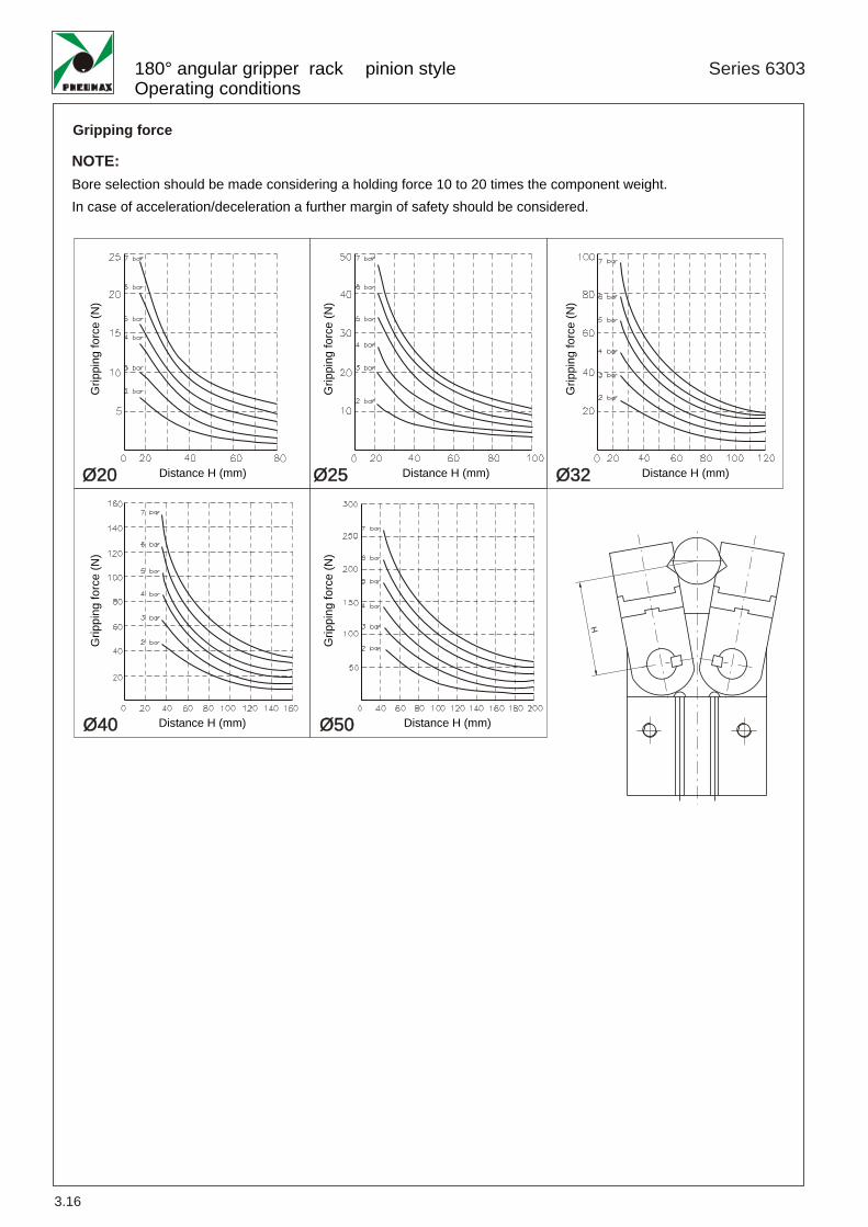
180° angular gripper rack pinion styleOperating conditions
Ø20 Ø25 Ø32
Ø40 Ø50
Bore selection should be made considering a holding force 10 to 20 times the component weight.In case of acceleration/deceleration a further margin of safety should be considered.
NOTE:
H
Gripping force
Grip
ping
forc
e(N
)
Distance H (mm)
Grip
ping
forc
e(N
)
Distance H (mm)
Distance H (mm) Distance H (mm)
Grip
ping
forc
e(N
)
Grip
ping
forc
e(N
)G
rippi
ngfo
rce
(N)
Distance H (mm)

3.17
3

3.18
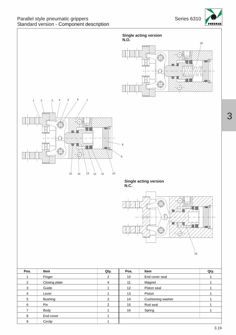
Parallel style pneumatic grippersStandard version - Component description
Series 6310
3.19
1 2 3 4 5 6 7
8
9
101112131415
16
16
Single acting versionN.O.
Single acting versionN.C.
3
Pos.123456789
Pos.10111213141516
ItemFingerClosing plateGuideLeverBushingPinBodyEnd coverCirclip
Qty.241122111
ItemEnd cover sealMagnetPiston sealPistonCushioning washerRod sealSpring
Qty.1111111

Series 6310
3.20
Holding force per finger
e = external holding forcei = internal holding force
Construction characteristics
Construction characteristics
Ordering code
9,8
30
42
65
6,3
24
28
45
N.O.
17
40
66
104
i
Parallel style pneumatic grippersStandard version - Ordering codes and technical data
6310.Ø.__
10162025
D = DNC = Single (N.C.)NO = Single (N.O.)
ouble actingactingacting
Magnetic sensors : see page 3.38 e 3.39
Bore
ø10
ø16
ø20
ø25
ee i iForce (N)
BodyPistonFingersEnd coverSeals
aluminiumaluminium or stainless steel (depending on the bore)steelaluminiumoil resistant NBR rubber
FluidWorking pressure
Operating temperature
filtered and non lubricated airødouble acting : 2 ÷ 7 bar for 10 - 1 ÷ 7 for other boresøsingle acting : 3,5 ÷ 7 bar for 10 - 2,5 ÷ 7 for other bores
-5°C ÷ +70°C
12
31
56
83
N.C.single actingdouble acting

Series 6310
3.21
AC
NA
LBEB
PP
P
G
FA
AB
E (2 threads)
DB
PA
NB
DA
PBø
FB
FC
GH
GFG
E
GM
GD
GD
EA
LALC
D (4 threads) DF (through hole)
C (4 threads)
GL
GC GB
A (2 threads)
F (connection for closing)F (connection for opening)
øM (H9)
Parallel style pneumatic grippersStandard version - Overall dimensions
Bore A AB AC C D DA DB ØDF E EA EB F FAØ10 M3x0,5 (useful depth 6) 27 11,4 M2,5x0,45 M3x0,5 (useful depth 5,5) 16 23 2,6 M3x0,5 (useful depth 6) 12 18 M3x0,5 11Ø16 M4x0,7 (useful depth 4,5) 30 16 M3x0,5 M4x0,7 (useful depth 8) 24 24,5 3,4 M4x0,7 (useful depth 8) 15 22 M5x0,8 13Ø20 M5x0,8 (useful depth 8) 35 18,6 M4x0,7 M5x0,8 (useful depth 10) 30 29 4,3 M5x0,8 (useful depth 10) 18 32 M5x0,8 15Ø25 M6x1 (useful depth 10) 36,5 22 M5x0,8 M6x1 (useful depth 12) 36 30 5,1 M6x1 (useful depth 12) 22 40 M5x0,8 20
Bore PA ØPB PPØ10 / / /Ø16 11,6 4 2,1Ø20 14 4 2,1Ø25 19 4 3,5
Sensor slot detail
GALC
øN (H9)
Bore FB FC G GB GC GA GD GE GF GH GL GM LA LB LC ØM ØN NA NB PØ10 9 19 12 5,7 3 6 4 15,2 11,2 57 5 29 37,8 23 16,4 11 (depth 2) 2 (depth 3) 7,6 5,2 5,4Ø16 7,5 19 15 7 4 7,5 5 20,9 14,9 67,3 8 38 45,5 30,6 23,6 17 (depth 2) 3 (depth 3) 11 6,5 5,8Ø20 10 23 20 9 5 9,5 8 26,3 16,3 84,8 10 50 52,8 42 27,6 21 (depth 3) 4 (depth 4) 16,8 7,5 9Ø25 10,7 23,5 25 12 6 11 10 33,3 19,3 102,7 12 63 63,6 52 33,6 26 (depth 3,5) 4 (depth 4) 21,8 10 11,5
49
5
52,8
M (H ) N (H )
3

Series 6310
3.22
Parallel style pneumatic grippersStandard version - Operating conditions
Ø25
Ø20
Ø16
Ø10
E TERNAL HOLD INTERNAL HOLD
Grip
ping
forc
e(N
)
Distance H (mm)
Double acting Single acting
Distance H (mm)Distance H (mm)Distance H (mm)
Grip
ping
forc
e(N
)
Grip
ping
forc
e(N
)
Grip
ping
forc
e(N
)
Grip
ping
forc
e(N
)G
rippi
ngfo
rce
(N)
Grip
ping
forc
e(N
)
Grip
ping
forc
e(N
)G
rippi
ngfo
rce
(N)
Grip
ping
forc
e(N
)
Grip
ping
forc
e(N
)G
rippi
ngfo
rce
(N)
Grip
ping
forc
e(N
)
Grip
ping
forc
e(N
)G
rippi
ngfo
rce
(N)
Grip
ping
forc
e(N
)G
rippi
ngfo
rce
(N)
External hold Force Internal hold Force Internal hold ForceExternal hold Force
Distance H (mm) Distance H (mm)Distance H (mm)Distance H (mm)
Distance H (mm) Distance H (mm)Distance H (mm)Distance H (mm)
Distance H (mm) Distance H (mm)Distance H (mm)Distance H (mm)
3.23
3

3.24

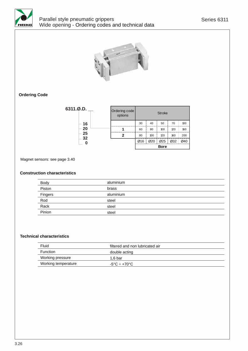
Parallel style pneumatic grippersWide opening - Component description
Series 6311
3.25
1
2 3 4 5 6
61920212223
7 8 9 10 11
12131415161718
Pos.123456789
101112
Pos.1314151617181920212223
ItemNutFingerWasherRackRod sealRack guiding bushBodyCirclipEnd coverPinion axisPinionSeal
Qty.428284111112
ItemPiston sealPistonMagnetPiston closing washerCushioning washerHolding ringBushingBushing sealRod sealCirclipPiston rod
Qty.22224444442
3
Series 6311
3.26
Construction characteristics
Technical characteristics
Ordering Code
Parallel style pneumatic grippersWide opening - Ordering codes and technical data
Magnet sensors: see page 3.40
Ordering codeoptions Stroke
30 40 50 70 100
1 60 80 100 120 160
2 80 100 120 160 200
Ø16 Ø20 Ø25 Ø32 Ø40Bore
6311.Ø.D. __
16202532
0
BodyPistonFingersRodRackPinion
aluminiumbrassaluminiumsteelsteelsteel
FluidFunctionWorking pressureWorking temperature
filtered and non lubricated airdouble acting1,6 bar-5°C ÷ +70°C
Series 6311
3.27
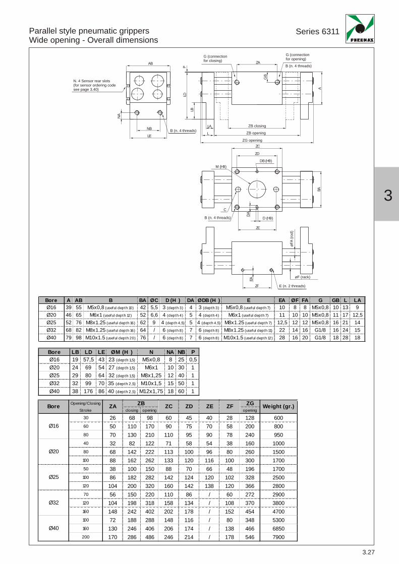
Parallel style pneumatic grippersWide opening - Overall dimensions
Opening/Closing ZGStroke closing opening opening
30 26 68 98 60 45 40 28 128 60060 50 110 170 90 75 70 58 200 80080 70 130 210 110 95 90 78 240 95040 32 82 122 71 58 54 38 160 100080 68 142 222 113 100 96 80 260 1500100 88 162 262 133 120 116 100 300 170050 38 100 150 88 70 66 48 196 1700100 86 182 282 142 124 120 102 328 2500120 104 200 320 160 142 138 120 366 280070 56 150 220 110 86 / 60 272 2900120 104 198 318 158 134 / 108 370 3800160 148 242 402 202 178 / 152 454 4700100 72 188 288 148 116 / 80 348 5300160 130 246 406 206 174 / 138 466 6850200 170 286 486 246 214 / 178 546 7900
Ø32
Ø40
Bore
Ø25
Ø20
ZEZB
Ø16
Weight (gr.)ZDZCZA ZF
Bore LB LD LE ØM (H ) N NA NB PØ16 19 57,5 43 23 (depth 1,5) M5x0,8 8 25 0,5Ø20 24 69 54 27 (depth 1,5) M6x1 10 30 1Ø25 29 80 64 32 (depth 1,5) M8x1,25 12 40 1Ø32 32 99 70 35 (depth 2,5) M10x1,5 15 50 1Ø40 38 176 86 40 (depth 2,5) M12x1,75 18 60 1
Bore A AB B BA ØC D (H ) DA ØDB (H ) E EA ØF FA G GB L LAØ16 39 55 M5x0,8 (useful depth 10) 42 5,5 3 (depth 3) 4 3 (depth 3) M5x0,8 (useful depth 7) 10 8 8 M5x0,8 10 13 9Ø20 46 65 M6x1 (useful depth 12) 52 6,6 4 (depth 4) 5 4 (depth 4) M6x1 (useful depth 7) 11 10 10 M5x0,8 11 17 12,5Ø25 52 76 M8x1.25 (useful depth 16) 62 9 4 (depth 4,5) 5 4 (depth 4,5) M8x1.25 (useful depth 7) 12,5 12 12 M5x0,8 16 21 14Ø32 68 82 M8x1.25 (useful depth 16) 64 / 6 (depth 8) 7 6 (depth 8) M8x1.25 (useful depth 11) 22 14 16 G1/8 16 24 15Ø40 79 98 M10x1.5 (useful depth 20) 76 / 6 (depth 8) 7 6 (depth 8) M10x1.5 (useful depth 12) 28 16 20 G1/8 18 28 18
øFA
(rod)
øF (rack)
3LD
BA
DAEA
NA
P
n. 4 cave porta sensore(per il codice di ordina ionedel sensore vedi pag.3.40)
ZB chiusa
ZC
ZD
DB (H9)
D (H9)
ZE
ZF
B (n. 4 filetti)
E (n. 2 filetti)
C
M (H9)
LA
L ZB aperta
ZG aperta
LB
NB
LE
ZA
GB
A
N (4 filetti)
G (connessione per la chiusura)AB
G (connessioneper l'apertura)
B (n. 4 threads)
E (n. 2 threads)
B (n. 4 threads)
B (n. 4 threads)ZB closing
ZB opening
ZG opening
G (connection for opening)G (connection
for closing)
N. 4 Sensor rear slots(for sensor ordering codesee page 3.40)
Series 6311
3.28
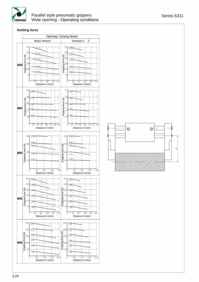
Parallel style pneumatic grippersWide opening - Operating conditions
Ø25
Ø20
Ø16
Ø32
Ø40
H
Holding force
Opening / Closing Stroke
Grip
ping
forc
e(N
)
Distance H (mm)
Basic Version Versions 1 2
Distance H (mm)
Distance H (mm) Distance H (mm)
Distance H (mm) Distance H (mm)
Distance H (mm) Distance H (mm)
Grip
ping
forc
e(N
)
Grip
ping
forc
e(N
)
Grip
ping
forc
e(N
)
Grip
ping
forc
e(N
)
Grip
ping
forc
e(N
)
Grip
ping
forc
e(N
)
Grip
ping
forc
e(N
)
Distance H (mm) Distance H (mm)
Grip
ping
forc
e(N
)
Grip
ping
forc
e(N
)

3.29
3

3.30

3
3 Finger parallel style pneumatic grippersComponent description
Series 6312
3.31
1 2 3 4 5 6
7
8
9
101112
Pos.123456
Pos.789101112
ItemPistonPiston nutEnd plateCirclipEnd plate sealBody
Qty.111111
ItemPiston sealMagnetWedge sealFingersWedgeCap
Qty.111311

Series 6312
3.32
Construction characteristics
Technical characteristics
Ordering code
3 Finger parallel style pneumatic grippersOrdering codes and technical data
For sensors P/N see page 3.38 e 3.39
6312.Ø.D
16202532
0506380100125
BodyPistonWedgeFingers
aluminiumaluminiumsteelsteel
FluidFunctionWorking pressureWorking temperature
filtered and non lubricated airdouble acting
(ø16 - ø20 - ø25) - 1 6 bar (ø32 ø125)2÷6 bar ÷ ÷ -5°C ÷ +70°C
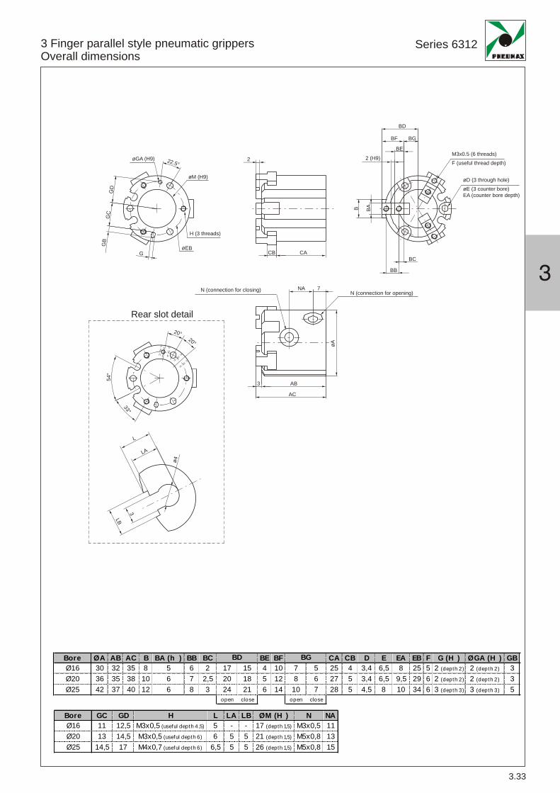
Bore ØA AB AC B BA (h ) BB BC BE BF CA CB D E EA EB F G (H ) ØGA (H ) GBØ16 30 32 35 8 5 6 2 17 15 4 10 7 5 25 4 3,4 6,5 8 25 5 2 (depth 2) 2 (depth 2) 3Ø20 36 35 38 10 6 7 2,5 20 18 5 12 8 6 27 5 3,4 6,5 9,5 29 6 2 (depth 2) 2 (depth 2) 3Ø25 42 37 40 12 6 8 3 24 21 6 14 10 7 28 5 4,5 8 10 34 6 3 (depth 3) 3 (depth 3) 5
open close open close
BD BG
3
Series 6312
3.33
3 Finger parallel style pneumatic grippersOverall dimensions
Bore GC GD H L LA LB ØM (H ) N NAØ16 11 12,5 M3x0,5 (useful depth 4,5) 5 - - 17 (depth 1,5) M3x0,5 11Ø20 13 14,5 M3x0,5 (useful depth 6) 6 5 5 21 (depth 1,5) M5x0,8 13Ø25 14,5 17 M4x0,7 (useful depth 6) 6,5 5 5 26 (depth 1,5) M5x0,8 15
M3x0.5 (6 threads)F (useful thread depth)
øD (3 through hole)øE (3 counter bore)EA (counter bore depth)
øM (H9)
øA
øGA (H9) 2 .5°2
°54
20°20°
3°3
H (3 threads)
GD
GC
GB
GBC
BAB
BB
CA
NA
ø4
LB
3
L
LA
AB
AC
3
7N (connection for closing)
Rear slot detail
N (connection for opening)
CBø BE
2 (H9)2
BE
BF BG
BD

Series 6312
3.34
3 Finger parallel style pneumatic grippersOverall dimensions ø32 80÷
Bore ØA AB AC AD B BA (h ) BB BC BE BF CA CB D E EA EB HØ32 52 41 44 3 14 8 11 4,5 32 28 9 20 12 8 30,5 6 4,5 8 9 44 M4x0,7 (useful depth 6)
Ø40 62 44 47 3 16 8 12 4,5 35 31 9 21 14 10 32 7 5,5 9,5 9 53 M5x0,8 (useful depth 7,5)
Ø50 70 52 55 3 18 10 14 5 41 35 10 24 17 11 37,5 9 5,5 9,5 12 62 M5x0,8 (useful depth 10)
Ø63 86 62 66 4 24 12 17 5,5 51 43 11 28 23 15 44 11 6,6 11 14 76 M6x1 (useful depth 9)
Ø80 106 77 82 5 28 14 20 6 63,5 53,5 12 32 31,5 21,5 56 12 6,6 11 19 95 M6x1 (useful depth 12)open close open close
BD BG
S (6 threads)
øD (3 through hole)øE (3counter bore)EA (counter bore depth)
°2020°
5°22.5°22.
20°
0°260
°
6 °0
6°0
øM (H9)
øGA (H9) 02 °
20°
H (3 threads)
ø EB
GD
GC
GB
G
L
Sensor slots detail
NA NB
ABAD
AC
N (connessione per la chiusura)
N (connessione per l'apertura)A
CACB
R
BC
BA(h
9)B
BB
BE
P
BF BGBD
Bore G (H ) ØGA (H ) GB GC GD L N ØM (H ) NA NB P (h ) R SØ32 3 (useful depth 3) 3 (useful depth 3) 5 19,5 22 6 M5x0,8 34 (useful depth 2) 16 8 2 2 M4x0,7 (useful depth 8)
Ø40 4 (useful depth 4) 4 (useful depth 4) 6 23,5 26,5 8 M5x0,8 42 (useful depth 2) 17 9 3 2 M4x0,7 (useful depth 8)
Ø50 4 (useful depth 4) 4 (useful depth 4) 6 28 31 7 M5x0,8 52 (useful depth 2) 20 9 4 2 M5x0,8 (useful depth 10)
Ø63 5 (useful depth 5) 5 (useful depth 5) 7 34,5 38 7,5 M5x0,8 65 (useful depth 2,5) 22 12 6 3 M5x0,8 (useful depth 10)
Ø80 6 (useful depth 6) 6 (useful depth 6) 8 43,5 47,5 9 G1/8 82 (useful depth 3) 27 13,5 8 4 M6x1 (useful depth 12)
N (connections for opening)
N (connections for closing)
3
Series 6312
3.35
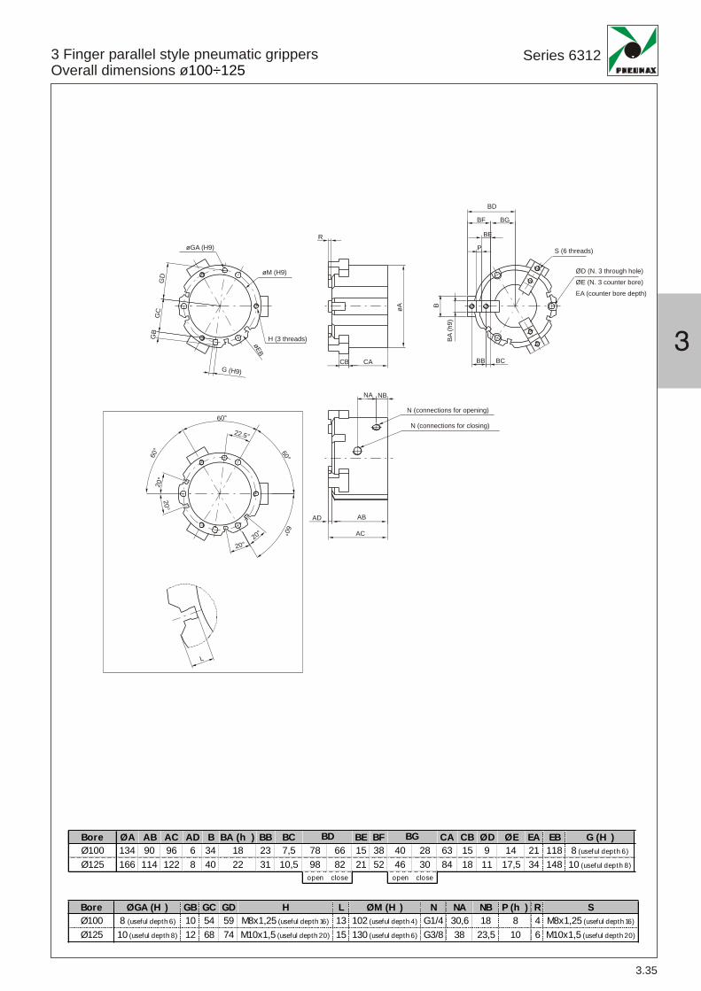
3 Finger parallel style pneumatic grippersOverall dimensions ø100÷125
Bore ØA AB AC AD B BA (h ) BB BC BE BF CA CB ØD ØE EA EB G (H )Ø100 134 90 96 6 34 18 23 7,5 78 66 15 38 40 28 63 15 9 14 21 118 8 (useful depth 6)
Ø125 166 114 122 8 40 22 31 10,5 98 82 21 52 46 30 84 18 11 17,5 34 148 10 (useful depth 8)open close open close
BD BG
Bore ØGA (H ) GB GC GD H L ØM (H ) N NA NB P (h ) R SØ100 8 (useful depth 6) 10 54 59 M8x1,25 (useful depth 16) 13 102 (useful depth 4) G1/4 30,6 18 8 4 M8x1,25 (useful depth 16)
Ø125 10 (useful depth 8) 12 68 74 M10x1,5 (useful depth 20) 15 130 (useful depth 6) G3/8 38 23,5 10 6 M10x1,5 (useful depth 20)
°22.5
øM (H9)
øGA (H9)
H (3 threads)
EBø
GD
GC
GB
G (H9)
L
NA NB
ABAD
AC
N (connections for closing)
N (connections for opening)øA
CACB
R
S (6 threads)
BC
BA(h
9)
B
BB
BE
P
BF BG
BD
20°2 °0
20°
02°
60°
60°60°
60°
ØD (N. 3 through hole)ØE (N. 3 counter bore)EA (counter bore depth)

Series 6312
3.36
3 Finger parallel style pneumatic grippersOperating conditions
H H
Ø16Ø16 Ø20Ø20 Ø25Ø25 Ø32Ø32
Ø40Ø40 Ø50Ø50 Ø63Ø63 Ø80Ø80
Ø100Ø100 Ø125Ø125
Grip
ping
forc
e(N
)
Distance H (mm) Distance H (mm) Distance H (mm) Distance H (mm)
Distance H (mm) Distance H (mm)
Distance H (mm) Distance H (mm) Distance H (mm) Distance H (mm)
Grip
ping
forc
e(N
)G
rippi
ngfo
rce
(N)
Grip
ping
forc
e(N
)G
rippi
ngfo
rce
(N)
Grip
ping
forc
e(N
)G
rippi
ngfo
rce
(N)
Grip
ping
forc
e(N
)
Grip
ping
forc
e(N
)G
rippi
ngfo
rce
(N)

3
3.37

3.38
Series 6300
1580.U1580.HAPMRS.UMHS.PMC1MC2MCH1MCH2
Reed bulb sensor with led and 2.5 m cablePNP sensor Hall effect with led and 2.5 m cableReed bulb sensor with led and connectorPNP sensor Hall effect with led and connectorM8 in line connector with 2.5 m cable (2 wires)M8 in line connector with 5 m cable (2 wires)M8 in line connector with 2.5 m cable (3 wires)M8 in line connector with 5 m cable (3 wires)
Sensor c/w 2,5 m. cable
Sensor c/w M8 connector (300 mm cable)
Ordering codes
Type of contactMaximum current (pulses of 0.5 sec)Maximum permanent currentMaximum permanent powerVoltage range A.C.Voltage range D.C.Working temperatureMaximum voltage dropCable sectionDegree of protectionConnecting timeDisconnecting timeAverage life (operations)Repetition of intervention point
Technical characteristics
6VA3 ÷ 30V3 ÷ 30V
4W/
12 ÷ 30V
3V
IP 65
± 0,1
2x0,14
0,5 ms0,1 ms
710
3x0,14
0,8 μs0,3 μs
910
-20° C ÷ 70°C
0,1A0,1A
0,2A0,2A
1580.U 1580.HAP
NOTE: Pay attention to the connected loads which should not exceed recommendations
*Reed bulb sensor: connection can be done either to negative or positive pole
MRS.U MHS.P
Diagrams andconnection
With Reed bulb
Hall effect
Weight gr. 27
Weight gr. 15
6,5 5
29
4,3
3
26,5
M8x
1
29 300 mm
bn
bl
LOAD
blue
brownbrown
black
*LOAD*LOAD
N.O.
Pneumatic grippersMagnetic sensor series 1580

3
Serie 6300
3.39
1581.U1581.HAP1581.HAN
Reed bulb sensor with led and 1 m cablePNP sensor Hall effect with led and 1 m cableNPN sensor Hall effect with led and 1 m cable
Sensor c/w 1 m. Cable
Ordering codes
Technical characteristics
5÷120VDC/AC 5 ÷ 30V DC
0,5V/
N.O.
IP 672, ø2,8 3,ø2,8
-10° C ÷ 70°C
100mA10W
200mA6W
1581.U 1581.HAN1581.HAP
bn
bl
LOAD
blue
brownbrown
black
*LOAD*LOAD
NPN
PNP
blue
LOAD
brownbrown
black
Type of contactMaximum currentMaximum permanent powerVoltage rangeWorking temperatureMaximum voltage dropCable sectionDegree of protection
Diagrams andconnection
With Reed bulb
Hall effect
Pneumatic grippersMagnetic sensor series 1581 (circular section)

Series 6300
3.40
Sensor c/w 1 m. Cable
bn
bl
LOAD
blue
brownbrown
black
*LOAD*LOAD
NPN
PNP
blue
LOAD
brownbrown
black
5,1
4
4
25,5 2,8
1582.U1582.HAP1582.HAN
Reed bulb sensor with led and 1 m cablePNP sensor Hall effect with led and 1 m cableNPN sensor Hall effect with led and 1 m cable
Ordering codes
Technical characteristics
5÷120VDC/AC 5÷30V DC
0,5V/
N.O.
IP 672, ø2,8 3,ø2,8
-10° C ÷ 70°C
100mA10W
200mA6W
1582.U 1582.HAN1582.HAP
Type of contactMaximum currentMaximum permanent powerVoltage rangeWorking temperatureMaximum voltage dropCable sectionDegree of protection
Diagrams andconnection
Hall effect
With Reed bulb
Pneumatic grippersMagnetic sensor series 1582

4
Manipulation Series 6400
ROTAR ACTUATORS
Double rack Rotary actuatorswith turn tableSeries 6 00
Single rack Rotary actuatorsSeries 6 10
Component descriptions
Ordering codes, technical data
Overall dimensions
Operating conditions
4.1
4.2
4.3
4.4
Page
Component descriptions
Ordering codes, technical data
Overall dimensions
Operating conditions
Magnetic sensors
4.5
4.6
4.7
4.8
4.9
4
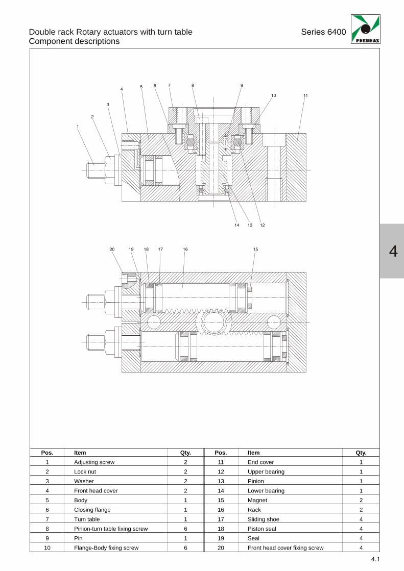
Double rack Rotary actuators with turn tableComponent descriptions
Series 6400
4.1
1
3
45 6 7 8 9
10 11
121314
151617181920
2
Pos.123456789
10
Pos.11121314151617181920
ItemAdjusting screwLock nutWasherFront head coverBodyClosing flangeTurn tablePinion-turn table fixing screwPinFlange-Body fixing screw
Qty.2222111616
ItemEnd coverUpper bearingPinionLower bearingMagnetRackSliding shoePiston sealSealFront head cover fixing screw
Qty.1111224444

4.2
Series 6400Double rack Rotary actuators with turn tableOrdering codes, technical data
Ordering code
10 (piston ø15)30 (piston ø21)50 (piston ø25)100 (piston ø32)200 (piston ø40)
A = StandardR = Cushioning
6 00. _ . _
Construction characteristics
Technical characteristics
NOTE : Magnetic sensors see page 4.9
aluminium alloysteelsteelNBR rubbersteelsteelsteelelastic bumper (hydraulic damper available on request)
BodyCover plateEnd platePiston sealPinionRackTurn tableCushioning
FluidMax. pressureWorking temperatureRotation angle rangeMax. rotationRotation speed
filtered and non lubricated air(for type 100 and 200, 6 bar)10 bar
-5°C ÷ +70°C0 ÷ 190°190°0,2 ÷ 1 sec/90°
4
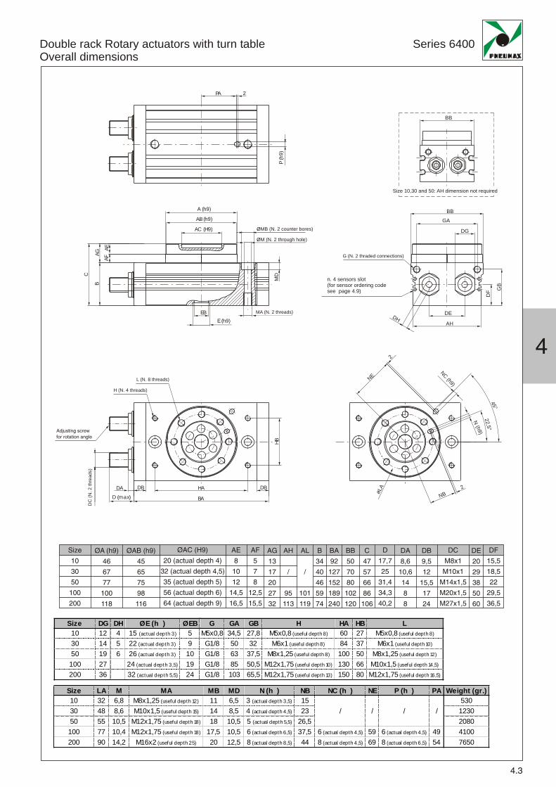
Size LA M MA MB MD N (h ) NB NC (h ) NE P (h ) PA Weight (gr.)10 32 6,8 M8x1,25 (useful depth 12) 11 6,5 3 (actual depth 3,5) 15 53030 48 8,6 M10x1,5 (useful depth 15) 14 8,5 4 (actual depth 4,5) 23 123050 55 10,5 M12x1,75 (useful depth 18) 18 10,5 5 (actual depth 5,5) 26,5 2080100 77 10,4 M12x1,75 (useful depth 18) 17,5 10,5 6 (actual depth 6,5) 37,5 6 (actual depth 4,5) 59 6 (actual depth 4,5) 49 4100200 90 14,2 M16x2 (useful depth 25) 20 12,5 8 (actual depth 8,5) 44 8 (actual depth 4,5) 69 8 (actual depth 6,5) 54 7650
/ // /
4.3
Series 6400Double rack Rotary actuators with turn tableOverall dimensions
BB
Grandezze 10, 30 e 50: quota AH assente
BB
N(h9)
NC(h9)
øLA
NB
NE
PA 2
P(h
9)
A (h9)
AB (h9)
AC (H9)
E (h9)EB
HA DBDBDAD (max) BA
MA (n. 2 filetti)
M (n. 2 fori passanti)
L (n. 8 filetti)
H (n. 4 filetti)
Viti regola ioneangolo rota ione
DC(n
.2file
tti)
MD
HB
BAF
AE
C
AG
MB (n. 2 lamature)GA
DG
DF
DE
AH
45°2
52
,°
HD
n. 4 sensors slot(for sensor ordering codesee page 4.9) G
B
2
2
Size DG DH ØE (h ) ØEB10 12 4 15 (actual depth 3) 530 14 5 22 (actual depth 3) 950 19 6 26 (actual depth 3) 10
100 27 24 (actual depth 3,5) 19200 36 32 (actual depth 5,5) 24
G GA GB H HA HB LM5x0,8 34,5 27,8 M5x0,8 (useful depth 8) 60 27 M5x0,8 (useful depth 8)
G1/8 50 32 M6x1 (useful depth 8) 84 37 M6x1 (useful depth 10)
G1/8 63 37,5 M8x1,25 (useful depth 8) 100 50 M8x1,25 (useful depth 12)
G1/8 85 50,5 M12x1,75 (useful depth 10) 130 66 M10x1,5 (useful depth 14,5)
G1/8 103 65,5 M12x1,75 (useful depth 13) 150 80 M12x1,75 (useful depth 16,5)
ØMB (N. 2 counter bores)
ØM (N. 2 through hole)
G (N. 2 thraded connections)
MA (N. 2 threads)
Size 10,30 and 50: AH dimension not required
L (N. 8 threads)
H (N. 4 threads)
DC
(N.2
thre
ads)
Adjusting screw
for rotation angle
Size
10
30
50
100
200
ØA (h9)
46
67
77
100
118
ØAB (h9)
45
65
75
98
116
ØAC (H9)
20 (actual depth 4)
32 (actual depth 4,5)
35 (actual depth 5)
56 (actual depth 6)
64 (actual depth 9)
AE
8
10
12
14,5
16,5
AF
5
7
8
12,5
15,5
AG
13
17
20
27
32
AH
/
95
113
AL
/
101
119
B
34
40
46
59
74
BA
92
127
152
189
240
BB
50
70
80
102
120
C
47
57
66
86
106
D
17,7
25
31,4
34,3
40,2
DA
8,6
10,6
14
8
8
DB
9,5
12
15,5
17
24
DC
M8x1
M10x1
M14x1,5
M20x1,5
M27x1,5
DE
20
29
38
50
60
DF
15,5
18,5
22
29,5
36,5
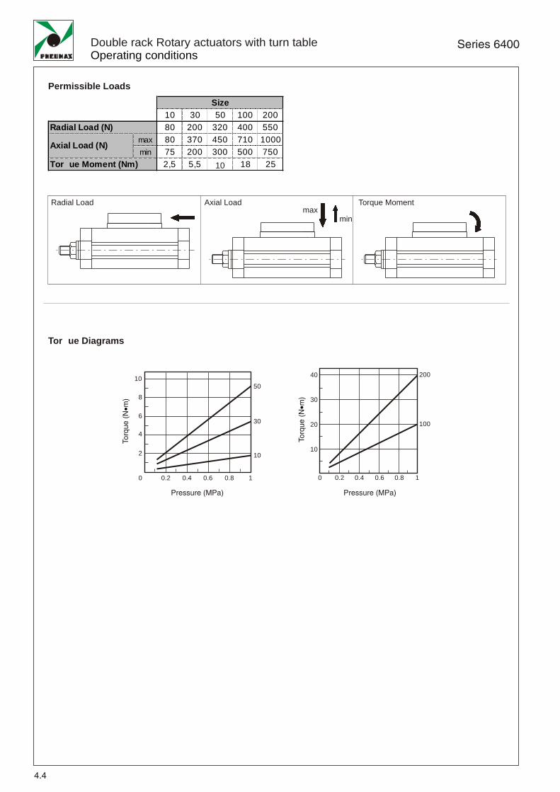
10 30 50 100 20080 200 320 400 550
max 80 370 450 710 1000min 75 200 300 500 750
2,5 5,5 9,5 18 25
Axial Load (N)
Size
Radial Load (N)
Tor ue Moment (Nm) 10
maxmin
Permissible Loads
Radial Load Axial Load Torque Moment
Series 6400
4.4
Double rack Rotary actuators with turn tableOperating conditions
Tor ue Diagrams
10
8
6
4
2
0 0.2 0.4 0.6 0.8 1
10
30
50
Pressure (MPa)
To
rqu
e(N
m)
•
100
20040
30
20
10
0 0.2 0.4 0.6 0.8 1
Pressure (MPa)
To
rqu
e(N
m)
•
4
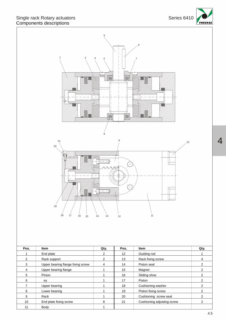
Single rack Rotary actuatorsComponents descriptions
Series 6410
4.5
1 3 4
5
6
7
8
9 10
1112131415161718
19
20
21
2
Pos.123456789
1011
Pos.12131415161718192021
ItemEnd plateRack supportUpper bearing flange fixing screwUpper bearing flangePinion
eyUpper bearingLower bearingRackEnd plate fixing screwBody
Qty.22411111181
ItemGuiding rodRack fixing screwPiston sealMagnetSliding shoePistonCushioning washerPiston fixing screwCushioning screw sealCushioning adjusting screw
Qty.1422222222
4.6
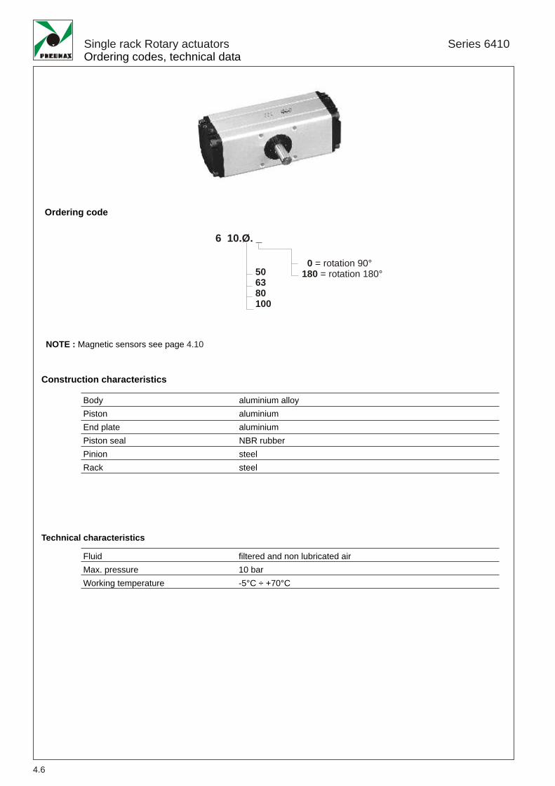
Single rack Rotary actuatorsOrdering codes, technical data
Series 6410
0 = rotation 90°180 = rotation 180°50
6380100
6 10.Ø. _
Ordering code
NOTE : Magnetic sensors see page 4.10
Construction characteristics
Technical characteristics
aluminium alloyaluminiumaluminiumNBR rubbersteelsteel
BodyPistonEnd platePiston sealPinionRack
FluidMax. pressureWorking temperature
filtered and non lubricated air10 bar-5°C ÷ +70°C
4
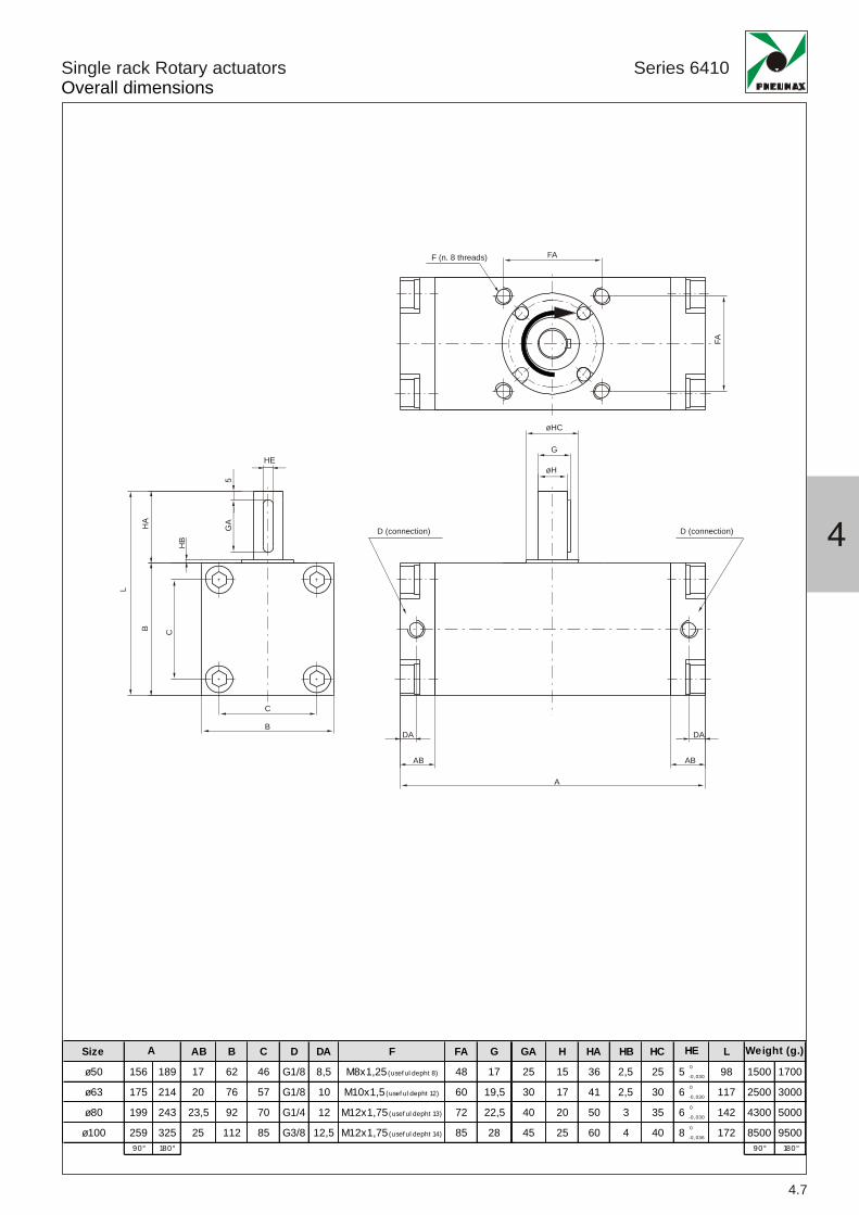
Size AB B C D DA F FA G
ø50 156 189 17 62 46 G1/8 8,5 M8x1,25 (usef ul depht 8) 48 17
ø63 175 214 20 76 57 G1/8 10 M10x1,5 (usef ul depht 12) 60 19,5
ø80 199 243 23,5 92 70 G1/4 12 M12x1,75 (usef ul depht 13) 72 22,5
ø100 259 325 25 112 85 G3/8 12,5 M12x1,75 (usef ul depht 14) 85 2890° 180°
A GA H HA HB HC L
25 15 36 2,5 25 5 0
-0, 030 98 1500 1700
30 17 41 2,5 30 6 0
-0, 030 117 2500 3000
40 20 50 3 35 6 0
-0, 030 142 4300 5000
45 25 60 4 40 8 0
-0, 036 172 8500 950090° 180°
HE Weight (g.)
4.7
L
BH
A
HB
GA
5
C
A
AB
DA
C
HE
BDA
AB
øHC
D (connection) D (connection)
øH
G
FA
FA
F (n. 8 threads)
Single rack Rotary actuatorsOverall dimensions
Series 6410

ø50 ø63 ø80 ø100
Max inetic energy ( g cm) 10 15 20 30
Size
50 63 80 100Radial Load (N) 200 300 400 600Compression Axial Load (N) 500 600 900 1000Tensile Axial Load (N)
Size
200
001ezi
S
08eziS
36eziS
05
eziS
Tor ue Diagrams 1.5
1
0.5
0 2 4 6 8 10
15
10
5
0 2 4 6 8 10
To
rqu
e(K
gf*
m)
Pressure (bar) Pressure (bar)
To
rqu
e(K
gf
m)
•
4.8
CompressionAxial Load
TensileAxial Load
Radial Load
Single rack Rotary actuatorsOperating conditions
inetic energy (cushioning angle 35 )
Rotation time according to inertial moments
Allowable Loads
Inertial moments ( g•cm•sec )
Rot
atio
ntim
e(s
ec./9
0°)
Series 6410

4
4.9
Single rack Rotary actuatorsMagnetic sensor series 1581 (circular section)
1581.U1581.HAP1581.HAN
Technical characteristics
5÷120VDC/AC 5 30V DC
0,5V2,5 V
N.A.
IP 672, ø2,8 3,ø2,8
-10° C ÷ 70°C
100mA10W
200mA6W
1581.U 1581.HAN1581.HAP
bn
bl
LOAD
blue
brownbrown
black
*LOAD*LOAD
NPN
PNP
blue
LOAD
brownbrown
black
Reed bulb sensor with led and 1 m cablePNP sensor Hall effect with led and 1 m cableNPN sensor Hall effect with led and 1 m cable
Sensor c/w 1 m. Cable
Ordering codes
Type of contactMaximum currentMaximum permanent powerVoltage rangeWorking temperatureMaximum voltage dropCable sectionDegree of protection
Diagrams andconnection
With Reed bulb
Hall effect
Series 6410

6,5 5
32
4,3
3
30
M8x
1
32 300 mm
Single rack Rotary actuatorsMagnetic sensor series 1580
Reed bulb sensor with led and 2.5 m cablePNP sensor Hall effect with led and 2.5 m cableReed bulb sensor with led and connectorPNP sensor Hall effect with led and connectorM8 in line connector with 2.5 m cable (2 wires)M8 in line connector with 5 m cable (2 wires)M8 in line connector with 2.5 m cable (3 wires)M8 in line connector with 5 m cable (3 wires)
Sensor c/w M8 connector (300 mm cable)
Ordering codes
Type of contactMaximum current (pulses of 0.5 sec)Maximum permanent currentMaximum permanent powerVoltage range A.C.Voltage range D.C.Working temperatureMaximum voltage dropCable sectionDegree of protectionConnecting timeDisconnecting timeAverage working periodRepetition of intervention point
NOTE: Pay attention to the connected loads which should not exceed recommendations
*Reed bulb sensor: connection can be done either to negative or positive pole
With Reed bulb
Hall effect
Weight gr. 27
Weight gr. 15
Series 6410
1580.U1580.HAPMRS.UMHS.PMC1MC2MCH1MCH2
Sensor c/w 2,5 m. cable
Technical characteristics
6VA3 ÷ 30V3 ÷ 30V
4W/
12 ÷ 30V
3V
N.A.
IP 65
± 0,1
2x0,14
0,5 ms0,1 ms
710
3x0,14
0,8 ms0,3 ms
910
-20° C ÷ 70°C
0,1A0,1A
0,2A0,2A
1580.U 1580.HAPMRS.U MHS.P
Diagrams andconnection
bn
bl
LOAD
blue
brownbrown
black
*LOAD*LOAD
4.10