GUIDE TO USING SAITEK GAMING EXTENSIONS (SGE) · PDF fileGUIDE TO USING SAITEK GAMING...
40
GUIDE TO USING SAITEK GAMING EXTENSIONS (SGE) Introduction What is SGE How We Make Game Profiles Here at Saitek Programming Commands Method A Method B Advanced Programming Cyborg 3D USB Stick & Cyborg 3D Digital II Shift Function Hat Switch Stick Axis Configuration P750, P1500 and P2000 Pads Shift Function Hat Switch Stick Axis Configuration GM2 Hat Switch Thumb Wheel Shift Function X36 Flight Controller/X45 Flight Controller Hat Switch Rotaries Pinkie Switch Mode Switch P8000/PC Dash 2 Button Properties More SGE Features… Printing Importing and Exporting a Profile Importing Exporting a Profile
Transcript of GUIDE TO USING SAITEK GAMING EXTENSIONS (SGE) · PDF fileGUIDE TO USING SAITEK GAMING...

GUIDE TO USING SAITEK GAMING EXTENSIONS (SGE)Introduction
What is SGE
How We Make Game Profiles Here at Saitek
Programming Commands
Method A
Method B
Advanced Programming
Cyborg 3D USB Stick & Cyborg 3D Digital II
Shift Function
Hat Switch
Stick Axis Configuration
P750, P1500 and P2000 Pads
Shift Function
Hat Switch
Stick Axis Configuration
GM2
Hat Switch
Thumb Wheel
Shift Function
X36 Flight Controller/X45 Flight Controller
Hat Switch
Rotaries
Pinkie Switch
Mode Switch
P8000/PC Dash 2
Button Properties
More SGE Features…
Printing
Importing and Exporting a Profile
Importing
Exporting a Profile
What to do if a profile isn’t there for your controller
Advanced Command Creation
Extended Commands
Cycle Commands
Application Commands
Website Commands
Troubleshooting Your Profiles
IMPORTANT!! – PLEASE READ
The first thing to say about Saitek Gaming Extensions (SGE) is that with the exception of afew products (GM2, GM3, P8000/PCDash 2) IT IS NOT REQUIRED TO MAKE THECONTROLLER WORK IN THE GAME. Most of the controllers just need to be set up andcalibrated within Game Controllers > Gaming Options in the Control Panel in Windows® inorder for the games to be able to recognise them. You then need to tell the game that youwant to use a joystick/pad/wheel from within the game’s options menus and that’s all there isto it. Most games these days also have control configuration screens built into them whereyou can set up each button on your controller to do what you want it to in the game.
The presence of such a screen in a game essentially negates the need for SGE to be used,as SGE is just simply software that enables you to program each button on the controller todo what you want it to in the game. Controllers that really don’t require the use of SGE includethe Cyborg USB stick, P750, P1500, P2000 and the R100 USB Wheel. The one feature of theabove products that might attract you to using SGE is the "shift" button feature that can befound on the stick and the pads; this allows you to essentially "double up" the commands thatcan be assigned to each button but this will be explained later on in the AdvancedProgramming section of this guide.
The controllers that really do have to use SGE are the GM2, GM3 and the PCDash 2/P8000 -as these rely on essentially "replacing" the keyboard. The X36 Flight Controller and X45 FlightController also really need to be programmed to gain full use of all their features and theirmultiple modes although, like the Cyborg stick and the pads, they operate perfectly well withingames without programming.
IntroductionWhat is SGE
Every game that you buy has a list of functions and commands built into it. A Flight Simulator,for example, often has a host of commands one of which might be the landing gear. The keyon the keyboard that this command is usually assigned to is G. SGE allows you to make thebuttons on your controller emulate a key (or combination of keys – more on that later) fromthe keyboard - so you could have any button on your controller perform as the key in order forit to activate the landing gear.
However, this programmability is not limited to the buttons, every part of the controller isprogrammable including the hat switches and axis movements (up, down, left and right on astick – even the throttle and rudder can be configured if your controller has them but theyusually don’t need to be). The rest of this guide will start with the basics of creating andassigning commands and then move onto controller-specific sections and advanced features.
How We Make Game Profiles Here at Saitek

The product manual that came with your controller just covers the basic aspects ofprogramming your controller. This guide will show you how WE make a profile when creatingthem for the website.
The first step is to read the guide that came with your game. As mentioned in the introduction,every game has a list of commands that have been assigned to different keys on thekeyboard. If you don’t have a manual then you are going to need to find out what key doeswhat on the keyboard - the game may have a list of commands in an option menu somewhereso you can also copy these out to a piece of paper. Either way, you need a list of commandswith the associated keyboard presses so you know what you are going to be programming.
Firstly, you need to first create a Profile within Saitek Gaming Extensions, so open up theSaitek Gaming Extensions Window and you will see a view like this.
You need to double-click on New Game Wizard and you will start a step-by-step process forcreating a new profile. There are only two screens that you actually need to worry aboutduring this process.
The first screen is basically just a starter screen explaining that you are running the NewGame Wizard, so just click on Next – it will take you get to the first screen that we need tolook at.

When you first open this screen, the wizard immediately starts searching your computer for allthe .exe files on your computer. The .exe files are the files that actually run all of yourprograms - so you will probably notice that the list of programs in here includes manyprograms that aren’t necessarily games, such as WordPad or Internet Explorer. Once it hasfinished searching you will see a list of possible choices. Initially, the list is in date order withthe most recently installed program at the top. However, if you click the Name bar at the topof the list of programs, it will shuffle these into alphabetical order, which might make it easierfor you to find the game that you’re after. Either way, simply select the game you want tocreate a profile for and then click Next.
The next screen checks what game you have selected and also gives you the option tochange the name of the profile or add a comment to the profile. Neither is really necessary,especially as they can be adjusted later once you have created the profile.
The screen after this has two checkboxes. The first says Set As Default Profile, you shouldusually leave this ticked otherwise the profile you are making won’t work. The other says UseTarget Directory and this should also be left ticked to ensure the profile will actually work.
The screen after is an important one – where you select the controller you want to use in theprofile. Obviously, you should select the controller you have but it is possible to select multiplecontrollers by holding down the Ctrl key on the keyboard and then clicking on all thecontrollers you want. In the example below you can see that We have selected the CyborgUSB stick, the GM2 Pad, the P750 Pad and the X36 Controller. For now, just select thecontroller you are using as you can always add controllers to your profile later, once it hasbeen created.

The next screen gives you the option to Disable The Buttons In this Profile that generallyyou should not do so leave that alone.
The final screen is there for you to check that the profile is set up as you desire. It lists thename of the profile, the target directory of where the game you are creating this profile for isinstalled and the controllers you are adding into this profile. Just click Finish to go back to theSaitek Gaming Extensions window and you will see the icon for your new profile appearnext to the New Game Wizard, Import Game Wizard and Default Profile.
Open up the profile by double-clicking on it and you will see the following screen.
Programming Commands
There are now two methods of programming commands to the buttons on your controller. Thefirst method that a lot of people use is to go straight into the 3D model of the controller andprogram there. This is fine for saving time but for some controllers it is not the best way to dothings. We will illustrate this method first and then go on to describe the method we use hereat Saitek.
Method A
Double-clicking on the controller icon (in this case the Saitek Cyborg 3D Stick USB) brings upthe 3D model of the controller. From here it is very easy to program the buttons to do whatyou want. Using the mouse, just click on the button you want to program and you will see itturn light blue in colour. At the bottom of the screen you can see four drop-down menus (wewill explain these later but they are fairly self explanatory) and a bar at the bottom that has anumber in it surrounded by a red circle. All you need to do is click in that bar (this highlightsthe number in blue) and then press the key on the keyboard that you want that button to befrom now on.

As you can see in the picture above we have programmed the trigger to be the G key on thekeyboard. Do the same for all your buttons and you have a configured stick – no need to savethe settings you have changed as they are automatically saved as you enter them. Just closethe SGE window and play the game and the buttons will now do what you tell them to.
For a controller like the Cyborg this is fine, but it doesn’t help when you are trying to createadvanced commands. In order to fully understand the Advanced Programming Section of thisguide that appears later, it will be easier if you use the following method.
Method B
Instead of going into the 3D model of the controller, open up the Command List by double-clicking on that icon instead. In here you will see a list of DirectX Button numbers. These arehere because each button on the stick has its own unique identifying number. Leave thesealone and point to a blank area of the window and right-click (click the right mouse button).You will get a drop-down menu appear with options in it; point to New and then click theCommand option that pops out from it.

You will then get a new icon underneath the DirectX Buttons called New Command – double-click on it to open it and you will see a Properties window pop-up. There is a box that saysName next to it and that will currently have the words New Command in it – simply type thename that you want this command to be. In the example below, we are creating a commandcalled Punch.
You can see that there are other settings that you can adjust here, but for the time being wejust want Single Action. The others will be explained in the Advanced Programming Sectionof the manual. Now you simply need to click the Action tab at the top and you will bepresented with the following screen.

Simply click in the white bar at the top and then press the key on the keyboard that activatesthe command that you are trying to create. You should see it appear in that bar, much like itdid in the example in Method A.
Now click Apply and then OK and you will be back at the Command List. You will see yournew command is now called what you renamed it to. If at any point after creating yourcommand you come back here and it is still called New Command then simply press F5 onthe keyboard to refresh the screen and it should then change to what you called it. Now, usingthe same method, create all the commands you want to program in and you will end up withsomething like below (obviously your command names will be different unless you are usingthe same game as we are in the example).

In the column on the left, click on the icon for your controller and this will bring up the 3Dmodel again. Using the mouse, click on the button you want to assign and then, instead ofclicking in the bar at the bottom, click the drop-down list on the right of the screen, underneaththe 3D view, as indicated in the picture below.

You can see that in that drop-down list all the commands that you created are present, sosimply scroll through the list until you find the command that you want to assign to this button.As soon as you do so you will see that in the bar at the bottom of the screen the key pressyou assigned to that command appears.

You can now go and program all your buttons in the same way. Initially this may seem like amore laborious method compared to Method A but the benefits will really become clear whenwe move onto Advanced Programming features like the hat switch or axes of a controller.Also, it helps if you create all of your commands first as you can then make sure that they areall present.
Advanced ProgrammingNow that we’ve covered the basics of creating commands in the command list and thenassigning them to buttons, we can move on to the more advanced parts of the controllers.This section will lead off with the Cyborg Stick, as it essentially contains all the features thatthe other controllers have to a greater or lesser degree. The sections that follow afterwardswill address specific controllers and the way in which configuring these functions differs butwill otherwise refer directly back to the explanation in the Cyborg Section. For example, all thecontrollers (with the exception of the R100 USB Wheel) have a shift function which isprogrammed in much the same way. There are some differences that occur because of otherfeatures on the controller and these are addressed in the controller-specific sections.
Finally, a section will follow that addresses advanced command creation – the SGE softwareis not just limited to single keystrokes for a command, as will be seen.
Cyborg 3D USB Stick & Cyborg 3D Digital II
Shift Function
To enable a shift button to act as a shift you need to bring up the 3D view of your controllerand double-click on the shift button on the 3D model. You will see a Properties screen likethe one below.

Simply change the Attribute of the button at the bottom from Action to Shift, as illustrated.You will see that the Action tab at the top of the window changes to Left Shift. Clicking onthis brings up the following screen;
This enables you to change the way the shift button operates. As the description at thebottom of that screen says, if you set the shift to operate as a Latched Shift it works muchlike the Caps Lock key on your keyboard. When you press it enables the shifted functionsuntil you press it again at which point it will return to Unshifted functions. If you leave it as anormal shift it will only enable the shifted functions whilst held down and return to unshiftedfunctions when released.
Programming shifted functions to your buttons is very similar to programming normalfunctions. Now that you have enabled the shift button to act as a shift you will find that thingsare a bit different when you open up the properties of the other buttons on the controller – likein the picture below.

As you can see, the drop-down commands menu next to Left Shift is now no longer greyedout like the Right Shift is and we can select a command from our drop-down list, just like wedid for the normal commands earlier on in this guide. Also, we can assign a differentcommand from the one that operates when the button is in its unshifted state. If we were toalso enable the Right Shift button on the controller as a shift rather than an action button youcan see that we could effectively assign a third command to every button. This can bring thenumber of assignable commands on the stick up from a basic 10 to a potential of 24commands! (58 commands if we include the 8 directions of the hat switch but this is not veryfeasible because of the difficulty of selecting a specific hat switch position when using thecontroller).
Hat Switch
The hat switch can be assigned shifted functions in a similar way but its properties screen willlook slightly different - as shown.
If you click the Unshifted tab then you will see that you can set the hat switch’s attributes asillustrated earlier in the manual and can now see when you click on the Left Shift or RightShift tabs a check box that says Use Unshifted Attributes.
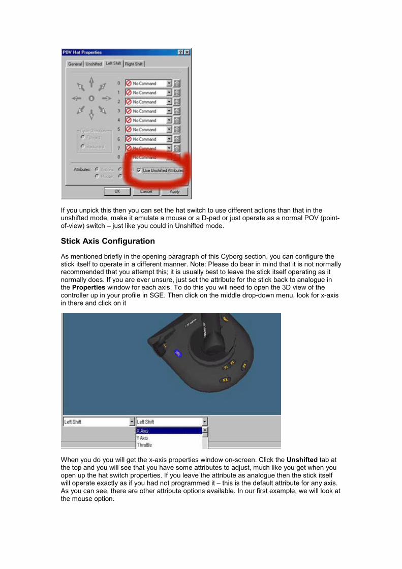
If you unpick this then you can set the hat switch to use different actions than that in theunshifted mode, make it emulate a mouse or a D-pad or just operate as a normal POV (point-of-view) switch – just like you could in Unshifted mode.
Stick Axis Configuration
As mentioned briefly in the opening paragraph of this Cyborg section, you can configure thestick itself to operate in a different manner. Note: Please do bear in mind that it is not normallyrecommended that you attempt this; it is usually best to leave the stick itself operating as itnormally does. If you are ever unsure, just set the attribute for the stick back to analogue inthe Properties window for each axis. To do this you will need to open the 3D view of thecontroller up in your profile in SGE. Then click on the middle drop-down menu, look for x-axisin there and click on it
When you do you will get the x-axis properties window on-screen. Click the Unshifted tab atthe top and you will see that you have some attributes to adjust, much like you get when youopen up the hat switch properties. If you leave the attribute as analogue then the stick itselfwill operate exactly as if you had not programmed it – this is the default attribute for any axis.As you can see, there are other attribute options available. In our first example, we will look atthe mouse option.

If we choose Mouse we get the option of what mouse axis we want to assign the currentlyselected axis to. In our example, we are adjusting the x-axis of the stick (left/right movement),so we would logically assign it to emulate the left/right motion of the mouse. If we configuredthe y-axis to emulate the up/down mouse motion then we would have a stick that operatedlike a mouse so you could effectively use it in games that don’t actually include joysticksupport like strategy games.
The banded mode is slightly different. If you select it you get a button called Edit Bands.
If you then click on this button you get the following screen.

This screen with increments from 0 – 100 describes the movement of the joystick across itscurrent axis. The red line indicates where the stick currently is positioned (at rest in thecentre). If you now move your stick you will see that the red line moves to correspond with themovement of the stick. If you move the stick fully left the red line goes to zero and if you movethe stick fully right the red line goes to 100. If we were adjusting the y-axis the red line wouldmove to zero if you pulled the stick back and up to 100 if you pushed the stick forwards.
What we can do here is set it up so that when the stick reaches a certain position it activatesa command that we have set up. First though, we have to "split" this axis.
There are two ways of doing this. One way is to move the stick so that the red line is at thepoint where you want the command to start and click the Split At Axis Position button. Theother way is to use your mouse and point to the position where you want the command tostart and then click the right mouse button. You will get a drop-down menu from which youcan choose the option Split Band. Either way, you will get something that looks like this.
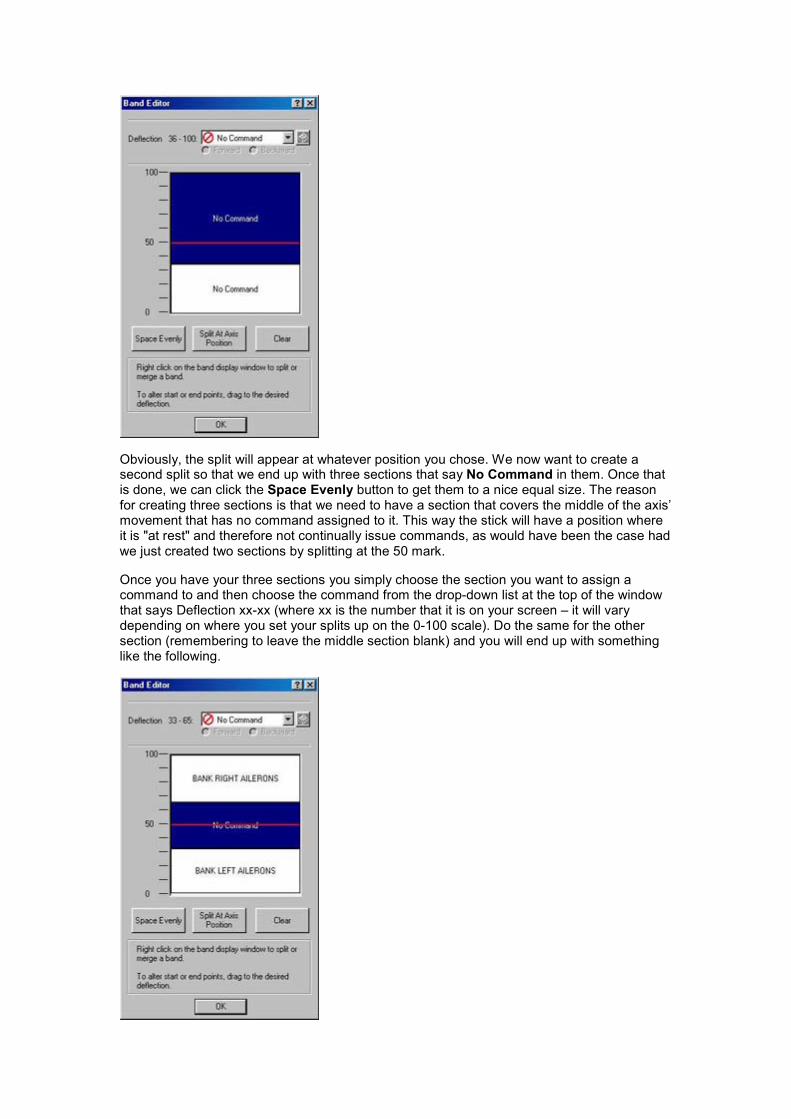
Obviously, the split will appear at whatever position you chose. We now want to create asecond split so that we end up with three sections that say No Command in them. Once thatis done, we can click the Space Evenly button to get them to a nice equal size. The reasonfor creating three sections is that we need to have a section that covers the middle of the axis’movement that has no command assigned to it. This way the stick will have a position whereit is "at rest" and therefore not continually issue commands, as would have been the case hadwe just created two sections by splitting at the 50 mark.
Once you have your three sections you simply choose the section you want to assign acommand to and then choose the command from the drop-down list at the top of the windowthat says Deflection xx-xx (where xx is the number that it is on your screen – it will varydepending on where you set your splits up on the 0-100 scale). Do the same for the othersection (remembering to leave the middle section blank) and you will end up with somethinglike the following.

In the example above, the Bank Left Ailerons command will be activated as soon as youmove the stick past the point where that "band" starts. Obviously you can assign anycommand you want to these banded areas. You might find it useful for games that onlyinclude keyboard support so you can assign the movement keys from the keyboard to thesepositions and the stick will then work in the game because it is "pretending" to be thekeyboard.
Remember that every axis on the stick, including the throttle and rudder can be configured inthis way.
Finally, if we go back to the properties screen of the axis we can see that just like with the hatswitch there are options for the two shifted modes at the top of the window so we could havethe stick operating differently for each shift mode.
P750, P1500 and P2000 Pads
Everything that can be done on the Cyborg stick can be done on the P-Series pads and inexactly the same way. There are just some minor differences that need clarifying.
Shift Function
Because of the way the controllers’ configuration changes when you change from Analogueto Digital control the shifted function is slightly more complex on the P-series pads. In thepicture above you can see a typical Properties screen of a button when the shift button hasbeen enabled as a shift function for the P2000 Tilt Pad. The P750 and P1500 obviously wouldnot have the extra options for the tilt + etc. as they do not have a tilt function. You can seehere that we could have 8 different assignments for the one button depending on what modethe pad is in. This obviously isn’t required and in practice you will find that you only need tomake sure that the shifted functions have one command assigned to them and the unshiftedcommands have another command assigned to them like in the picture below. This will avoidconfusion.

In the example above we can see that the shifted commands are Extend Flaps Fully and theunshifted commands are Lights On/Off. Using this, we avoid confusion by ensuring that nomatter what mode we are in, a shifted command is always going to be the same and thesame for the unshifted commands.
Hat Switch
Obviously, when the pad is in Digital Mode the hat switch is no longer a hat switch butreplaces the stick as the controller and this can lead to some possible confusion whenprogramming it. The hat switch can be programmed just like it can on the Cyborg stick (choiceof Actions, D-Pad (default in Digital mode), POV (default in Analogue mode) and mouse).Again, just like the buttons (explained just above) you should generally keep shiftedcommands the same as each other and do the same for unshifted commands (with theobvious exception that the hat switch’s attribute should be set to D-pad for any digital modesso that you still have movement control in the game. The different combinations of Digital,Digital+Shift etc. can be accessed by clicking on the tabs at the top of the Properties windowand if you can’t see a tab you want then click the little arrows at the top-right of the screen toscroll across to the tab you want.
Stick Axis Configuration
You have exactly the same options as you do on the Cyborg stick, except you have the samecomplications caused by the multiple modes of the pads, like with the buttons and hat switchabove. Otherwise the axes can be programmed in exactly the same way, which of coursealso includes the Throttle Wheel on the pads.
GM2
The GM2 Action Pad is one of the controllers that needs to be configured fully before it willwork correctly. A common mistake that is made is for people to forget about using SGE,enable joystick control within the game they are using and reassign the buttons to do whatthey want from within the game. This causes a few problems. First of all, the hat switch on theGM2 pad that is commonly used for movement in games can only be assigned to 4-waymovement. As soon as you try to get diagonal movement (forwards and left, backwards andright etc) the character you are controlling will just stand still because no command isassigned to the diagonal positions of the hat switch.
You will also find that if you enable joystick control within the game that it then picks up theThumb Wheel on the GM2 pad and it usually picks it up as the y-axis (up/down movement) ona joystick. Consequently, whatever you are controlling will immediately run forwards as soonas you get into the game (the assumption here is that you are using the GM2 with a firstperson shooter game such as Quake 3 Arena). Also, you will not be able to configure theThumb Wheel as you can using SGE.
The first lesson is to disable joystick support in the games you will be using the GM2 with, asthe GM2 is just a keyboard replacement that will be programmed with keyboard commands.
Assigning commands to the buttons on the GM2 is the same as that for any other SGE-supported controller and has already been described in the basic section of this manual so wewill examine the trickier aspects of the pad, using the example of a first person shooter gamelike Project I.G.I. from Eidos Interactive.
Hat Switch
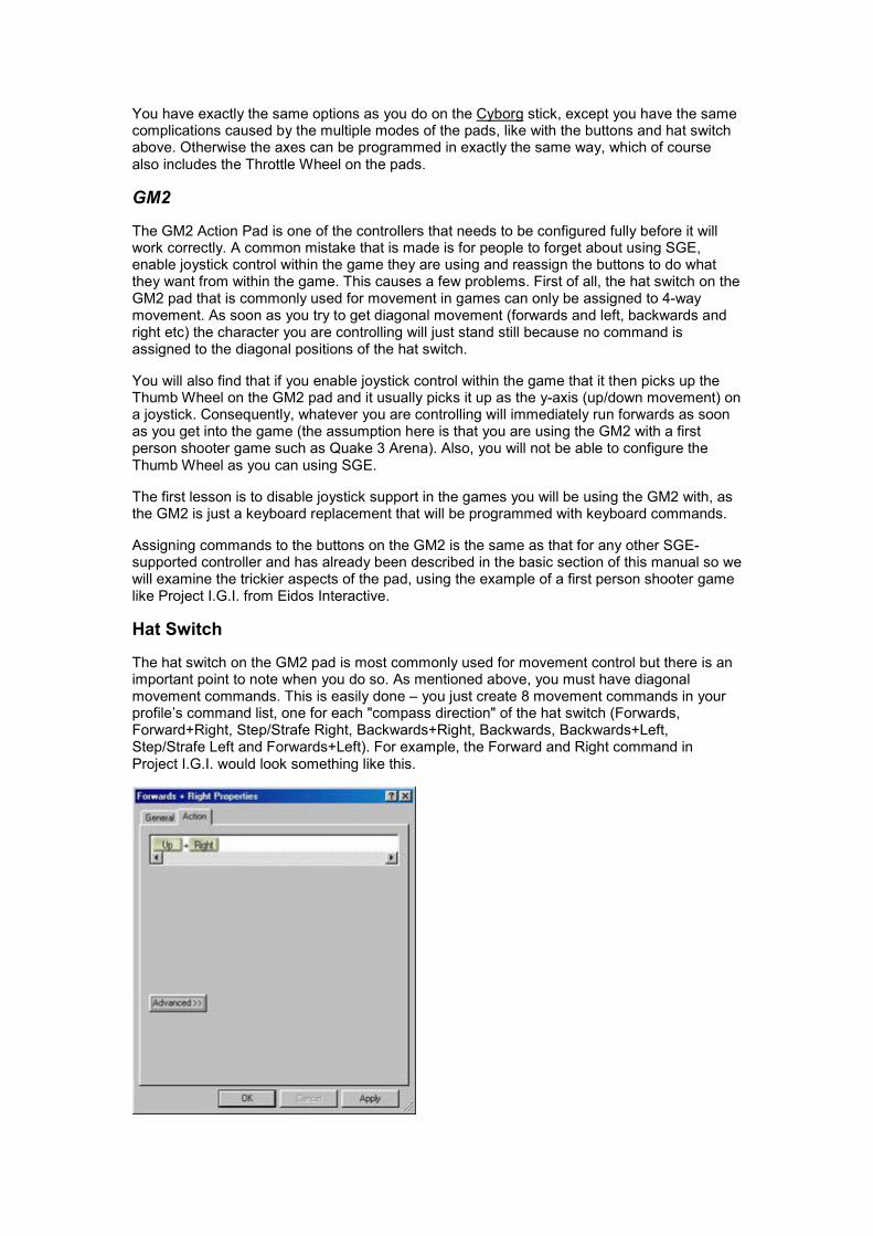
The hat switch on the GM2 pad is most commonly used for movement control but there is animportant point to note when you do so. As mentioned above, you must have diagonalmovement commands. This is easily done – you just create 8 movement commands in yourprofile’s command list, one for each "compass direction" of the hat switch (Forwards,Forward+Right, Step/Strafe Right, Backwards+Right, Backwards, Backwards+Left,Step/Strafe Left and Forwards+Left). For example, the Forward and Right command inProject I.G.I. would look something like this.
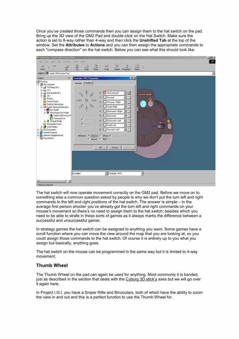
Once you’ve created those commands then you can assign them to the hat switch on the pad.Bring up the 3D view of the GM2 Pad and double-click on the Hat Switch. Make sure theaction is set to 8-way rather than 4-way and then click the Unshifted Tab at the top of thewindow. Set the Attributes to Actions and you can then assign the appropriate commands toeach "compass direction" on the hat switch. Below you can see what this should look like.
The hat switch will now operate movement correctly on the GM2 pad. Before we move on tosomething else a common question asked by people is why we don’t put the turn left and rightcommands to the left and right positions of the hat switch. The answer is simple – in theaverage first person shooter you’ve already got the turn left and right commands on yourmouse’s movement so there’s no need to assign them to the hat switch; besides which youneed to be able to strafe in these sorts of games as it always marks the difference between asuccessful and unsuccessful gamer.
In strategy games the hat switch can be assigned to anything you want. Some games have ascroll function where you can move the view around the map that you are looking at, so youcould assign those commands to the hat switch. Of course it is entirely up to you what youassign but basically, anything goes.
The hat switch on the mouse can be programmed in the same way but it is limited to 4-waymovement.
Thumb Wheel
The Thumb Wheel on the pad can again be used for anything. Most commonly it is banded,just as described in the section that deals with the Cyborg 3D stick’s axes but we will go overit again here.
In Project I.G.I. you have a Sniper Rifle and Binoculars, both of which have the ability to zoomthe view in and out and this is a perfect function to use the Thumb Wheel for.

To set this up we first need to have created our commands in the Command List asdescribed in the basic section of the manual. You will need to bring the properties of theThumb Wheel up on screen so go into the 3D view of the GM2 in your profile and double-clickon the Thumb Wheel. Click the Unshifted tab at the top of the Properties window and thenset the attributes to Banded.
You can then click the Edit Bands button to bring up the following screen.
This Band Editor window with increments from 0 – 100 describes the movement of theThumb Wheel. The red line indicates where the Thumb Wheel currently is positioned (at restin the centre). If you now move your Thumb Wheel you will see that the red line moves tocorrespond with the movement of the wheel. If you move the wheel fully left the red line goesto zero and if you move the wheel fully right the red line goes to 100.
What we can do here is set it up so that when the wheel reaches a certain position it activatesa command that we have set up. First though, we have to "split up" this axis.

There are two ways of doing this. One way is to move the wheel so that the red line is at thepoint where you want the command to start and click the Split At Axis Position button. Theother way is to use your mouse and point to the position where you want the command tostart and then click the right mouse button. You will get a drop-down menu from which youcan choose the option Split Band. Either way you will get something that looks like this.
Obviously, the split will appear at whatever position you chose. We now want to create asecond split so that we end up with three sections that say No Command in them. Once thatis done we can click the Space Evenly button to get them to an equal size. The reason forcreating three sections is that we need to have a section that covers the middle of the axis’movement that has no command assigned to it. This way, the wheel will have a positionwhere it is "at rest" and therefore not continually issue commands, as would have been thecase had we just created two sections by splitting at the 50 mark.
Once you have your three sections, you simply choose the section you want to assign acommand to and then choose the command from the drop-down list at the top of the windowthat says Deflection xx-xx (where xx is the number that it is on your screen – it will varydepending on where you set your splits up on the 0-100 scale). Do the same for the othersection (remembering to leave the middle section blank) and you will end up with something
like the following.

When we move the wheel right when the binoculars or the sniper mode on the rifle are in usethen the view will zoom in and if we move it left then the view will zoom out.
Again, as with the hat switch any command can be assigned to this Thumb Wheel. In othershooter games you may want to assign commands to the wheel for switching betweenweapons. Some strategy games have an option to rotate the view of the map/battle area youare viewing and the wheel is ideal for this.
Shift Function
This is programmed in precisely the same way as that for the Cyborg 3D Stick with theobvious exception that the GM2 only has one shift button whereas the Cyborg has two.
One final point for the GM2. We do get asked sometimes why the mouse buttons can’t bereprogrammed. The answer is quite simply that they don’t need to be. In all the games thatthe GM2 was designed to be used with, a left and right mouse button are needed to operatecommands in those games. It makes sense therefore to leave the mouse clicks on thebuttons that everyone uses every day whilst using their computer.
X36 Flight Controller/X45 Flight Controller
The X36/X45 looks complicated to program but it isn’t really. If you take everything you’velearned from the basic section of this manual and refer back to the sections for the Cyborgand GM2 controller then you really can’t go far wrong. The only complex part of the X36/X45is the sheer number of commands that you can assign to it. When you consider that everybutton, hat switch and rotary dial on the combo can have three different commands assignedto it for each of the three modes it sounds a lot. But you can double this number too when yourealise that every mode can have a shifted command assigned too because of the pinkie/shiftbutton – that’s a possible six commands per button.
Hat Switch
These are programmed in exactly the same way as the Cyborg stick.
Rotaries
These are programmed in exactly the same way as the GM2’s Thumb Wheel.

Pinkie Switch
This is programmed in exactly the same way as the shift button on the Cyborg stick.
Mode Switch
The three modes are exactly the same as the "two modes" provided by the Cyborg’s two shiftbuttons – except that you obviously have an extra mode to play with. You will find that theproperties of every axis (rotaries, throttle, rudder and x-axes) and hat switch has three tabs atthe top for each of the modes – this changes to six tabs when you enable the pinkie switch inits shifted function so you have Mode 1, Mode1 + Pinkie etc. as illustrated below.
The button properties look slightly different in that rather than tabs you have a list of drop-down menus like so;
Either way, commands can be assigned in the appropriate way so that you can set differentcommands for each mode/shift function etc.
P8000/PC Dash 2

The P8000 is programmable in exactly the same way as any other controller supported bySGE. It has a total of 37 buttons and a hat switch, all of which are programmable asdescribed in the basic and advanced section of the manual. One of those buttons canbecome a shift mode button to double up the number of commands to 72 plus the hat switchso it can be a very versatile device.
Bear in mind also that the P8000 doesn’t just have to be used for games. In its default settingthe buttons all activate different programs and features within Windows itself, such aslaunching Internet Explorer, opening your Word Processor or even SGE; they can all bereconfigured to do something else and this will be covered in the Advanced Programmingsection of this guide.
The main feature of the P8000 though (aside from it’s programmability) is the ability to print acommand overlay sheet that you can cut out and lay over the keys on the unit. This overlaysheet is divided into squares representing each button and, provided you created yourcommands as described in the basic section of this manual, they will have the name of thecommand that you assigned to it. Using the software you can change the background colourof each square so that you can have obvious groups of commands (weapon type commandscould all be red for example) for quicker and easier location of the command you want toactivate. Obviously, without this sheet it could be a tough job remembering what commandyou assigned to what key.
The method for printing this overlay is described in the printing section of this manual.
Button Properties
When you double-click on a button in the 3D view of the P8000 you get the followingProperties window.
It’s very similar to the Properties window that you get for other controllers but it has an extratab at the top called Display. This is where we adjust how the button appears on the overlaysheet.

Here you can change how the text appears on the button for your overlay sheet. The drop-down menu next to 1 allows you to adjust the font for the text. The drop-down menu next to 2allows you to adjust the size, 3 allows you to add Bold, Italicise or Underline settings andwhether you want the text to be centred or aligned to the left or right of the box it is in. 4allows you to adjust the colour settings – foreground adjusts the colour of the text andbackground the colour of the box the text will appear in. The box next to 5 allows you tochange the text that appears in the box and finally 6 allows you to see what it will all look likebefore you print.
Using this method it is possible to create simple command overlay sheets with commandsthat are grouped and arranged to your liking.
When checking for profiles on our website, you will see that some of them have moreelaborate looking command overlay sheets that you can download. These are created usingPaint Shop Pro – the software that is provided on the CD that came with your P8000 – but wewill not cover that here. Suffice to say that creation of such command sheets would require asecond manual; indeed buying a manual for Paint Shop Pro from a bookshop would be agood idea if you were interested in creating such command overlay sheets for yourself.
More SGE Features…Printing
After creating profiles for your controllers it can be easy to forget exactly what commands youhave assigned to what buttons. This can be especially annoying if you forget whilst playingyour game. Therefore we have included a printing option in SGE that prints out a CommandSheet. This lists each button/axis etc. on your controller, next to which it tells you the name ofthe command you have assigned to it and the associated keypress. Printing a CommandSheet is easy. Simply open up your game profile in SGE and then right-click on the controllericon within the profile. You will get a drop-down menu appearing, in which one of the optionsis Print. Simply click on this and a sheet will be printed on your printer, which lists each buttonand the commands associated to it.
The P8000 is slightly different. You actually have two print options with this controller and thisis reflected when you point to Print in that drop-down menu; you get two options pop out tothe side of it like below.

Clicking on Overlay will print out a command overlay sheet as described in the section of thismanual relating to P8000. Clicking on Configuration will print out a similar sheet to the oneyou get with all the other controllers.
Either way you can then use the printed sheet for reference to which command you haveassigned to a button on your controller.
Importing and Exporting a Profile
Before we move on to Advanced Command Creation, we will quickly show how to import apre-made profile and also how to export your profiles so you can back them up. The CD thatcame with your controller has a number of pre-made profiles on it and there are more addedto our website nearly every week. The benefit to you is that the profiles we make already haveall the basic commands from the game it was created for – this will save you the time andeffort of creating all those commands yourself. Any advanced, extended commands or cyclecommands you want to create can be added to the profile by yourself as described in theAdvance Command Creation section of this manual.
Importing
Importing is a simple step-by-step process just like creating a new profile. From the main SGEwindow, double-click on the Import Game Wizard icon to start importing a profile. The firstscreen is a simple welcome so you can just click Next. The next screen asks you if you wantto import an exported SGE file or a Command Centre file.
In the majority of cases you will be selecting an exported SGE file. The Command Centre filesare those that were created by the programming software for three of our older products – theoriginal Cyborg 3D Digital Stick and Pad and the PC Dash. These profiles are available onour website under the Cyborg 3D Digital’s files section but please bear in mind that importingthese will just import a command list – you will have to assign any commands to the buttonsas if starting from fresh.
For this example though select Exported SGE file and then click Next – you will get thefollowing screen.
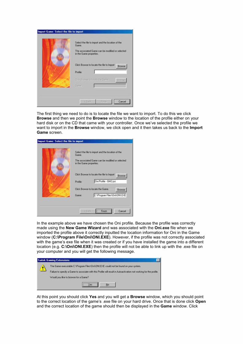
The first thing we need to do is to locate the file we want to import. To do this we clickBrowse and then we point the Browse window to the location of the profile either on yourhard disk or on the CD that came with your controller. Once we’ve selected the profile wewant to import in the Browse window, we click open and it then takes us back to the ImportGame screen.
In the example above we have chosen the Oni profile. Because the profile was correctlymade using the New Game Wizard and was associated with the Oni.exe file when weimported the profile above it correctly inputted the location information for Oni in the Gamewindow (C:\Program File\Oni\ONI.EXE). However, if the profile was not correctly associatedwith the game’s exe file when it was created or if you have installed the game into a differentlocation (e.g. C:\Oni\ONI.EXE) then the profile will not be able to link up with the .exe file onyour computer and you will get the following message.
At this point you should click Yes and you will get a Browse window, which you should pointto the correct location of the game’s .exe file on your hard drive. Once that is done click Openand the correct location of the game should then be displayed in the Game window. Click

Finish to finalise these settings and you will then have an icon for your new profile in the SGEwindow.
Exporting a Profile
All the profiles you can download are available because you can export any profiles you maketo a single file. This is a good thing to do just to have a backup of any profiles that you’vemade – having to create all those commands from scratch can be laborious. It’s very simpleto export a file – all you do is right-click on the profile in the SGE window and choose Export.
A window will then pop up asking you where you want to save the file to on your hard disk,also giving you the option to change the name of the file if you require. Make all your choicesand then click Save. That’s it – you’ve just exported a profile.
What to do if a profile isn’t there for your controller
A hypothetical situation - you are looking for a profile for a particular game for your controller,either on the website or on the CD. You can find one for another controller but not for yours;what do you do? The answer is to import that profile anyway because you can add acontroller into a profile whenever you like. This is another simple process. Once you’veimported the profile, open it up in the SGE window and then point to a blank area of thewindow and right-click the mouse. Point to New in the drop-down menu and then choose thecontroller you want to add from the pop-out list.
Once you’ve selected your controller you will see the icon for it appear within the profile. Youcan then double-click on it to bring up the 3D model and then begin assigning commands justas described in the basic section of this guide.
Advanced Command Creation

As mentioned earlier, you are not limited to single key presses when creating commands; infact command creation is only limited by what you want to do. As well as this you can assignthe opening of applications or even websites to the buttons on your controller. All this will becovered in this section.
Extended Commands
Open up a command and click the Action tab at the top of the window to bring up the barwhere you input your keystrokes. Now click the Advanced button on this window and you willget the following.
As you can see we have some new options on the screen now. In the command input bar wenow have three ‘columns’ that refer to the actual button on your controller you are configuring.Any keystroke we place in the press column will activate when we press the buttons on thecontroller. Any keystroke in the repeat column will activate as long as we hold down thebutton on the controller and the keystroke in the release column will be activated when we letgo of the button on the controller.
The mouse buttons allow us to make the button pretend to be a mouse button of our choiceand the Repeat Cycle sets how often the keystrokes placed in the Repeat column will repeatwhilst the button on the controller is held down. For example if we had keystrokes h,g,f in therepeat column then at the current setting in the picture above the software would wait .20 of asecond before repeating h,g,f whilst we held the button on the controller down.
So what does this allow us to do? Anything. One thing you will notice when inputtingkeystrokes whilst in Advanced Mode is that you get two keystrokes for every one key youpress – like below.
This is reflecting the way in which your keyboard actually works. When you press a key on akeyboard you actually get two signals – one when you press it and one when you release it.The numbers under the key presses above are the time (in seconds) between the key beingpressed and released – in this case it was a simple short keypress because the time is only.11 of a second. This time can be adjusted though. When creating the keypress the softwarewill record how long you pressed the key down for, so you can adjust it there by holding thekey down for how long you want it to be held down for. Alternatively, you can adjust the

timings below the key presses by using the mouse to ‘drag’ the time to your chosen setting.Simply point to the time you want to adjust and click and hold down the left mouse button.Now drag the mouse right or left to increase or decrease, respectively, the timing.
To give you an idea of what all this means together have a look at the below example.
Imagine we are playing a space combat simulator. When I press the button on the controllerthat this command is assigned to a missile is launched (Space). Whilst holding the buttondown the command switches to a Missile View (F6) so we can track the progress of themissile. It then waits 5 seconds before switching to a view of the enemy ship we havetargeted (F7). When we let go of the button it switches back to a view of our cockpit (F1).Note that unless we adjust the Repeat Cycle setting it will very quickly switch back to theMissile View if we leave the button on the controller held down so we may want to adjust theRepeat Cycle setting to something like 4.00 or 5.00 seconds.
This is just an example of what you can do with the Advanced Command editor.
Cycle Commands
If we go back to the General tab in the command properties we can see that there are othersettings we can assign to the button.
In this example we have changed the setting from Single Action to Cycle of Actions and youwill notice that the tab at the top of the window has changed from Action to Cycle. Clickingon this tab gives you the following screen.

A Cycle of Actions is basically a series of commands that you can assign to a single button.These commands are then activated in the order you assigned them each time you press thebutton that this Cycle of Actions has been assigned to. Looking at the picture above we arelooking at the list of commands created for the game Oni (the same one used in the basicsection of the manual). In this game you can use combinations of commands to create morepowerful move combinations. For example, if you were to press Punch, Punch, Kick it wouldexecute two punches and then a spinning kick. Rather than pressing two separate buttons wecould assign this cycle to the one button.
So all we do is select the first action in the cycle that we want to add in from the SingleActions column. Then we click the box with the arrow pointing to the right to add it in to theActions in Cycle column.
Do this for each command you want to place in the cycle and you will end up with somethinglike the above. Now, when we want to execute the combo move in Oni we simply need topress the same button three times and it will activate the punch command on the first press,the punch command again on the second press and then the kick command on the thirdpress. It will start the cycle from the beginning the next time you press the button. That’s allthere is to programming a Cycle of Actions.

Application Commands
Clicking the Application option in the General tab of a command properties page changesthe Action tab at the top to an Application tab. Clicking on this tab brings up the followingscreen.
This is a function that will mainly only be used with the P8000 but it can be done for anycontroller supported by SGE. Basically, you can assign any button on your controller tolaunch an application when you press it. This would only normally be used from withinWindows rather than in a game.
To choose the application you want to assign a command to simply click Browse and thenpoint it to the .exe file for the application you are looking to run from this button. In theexample below we have associated the button with the NotePad application in Windows.
Here you can choose anything you want – you can even assign the buttons to launch yourfavourite games.
You can also access the application setup from the 3D model of the controller as indicated inthe picture below.

Simply click on the button you want to assign and then from the drop-down menu at thebottom of the screen, choose Application. You can then click the Set-up button and thenBrowse for the .exe file for your application or game just as described above.
Website Commands
Finally, it is possible to assign a button to open specific Website addresses. Again this isgoing to be mainly used by the P8000 but any controller supported by SGE can do it.Selecting the Website option in the Command Properties window will change the tab at thetop to Web Command and clicking on this will bring up the following window.

Simply type in the address of the website you wish to assign to this command (e.g.www.saitek.com). Clicking Browse will take you to the Favourites folder in Windows whereany websites that you have bookmarked will be saved, so you can also select any websitesfrom there.
As with the Application option you can also set up website commands to buttons from the 3Dmodel of the controller, using the drop-down list at the bottom of the screen – as below.
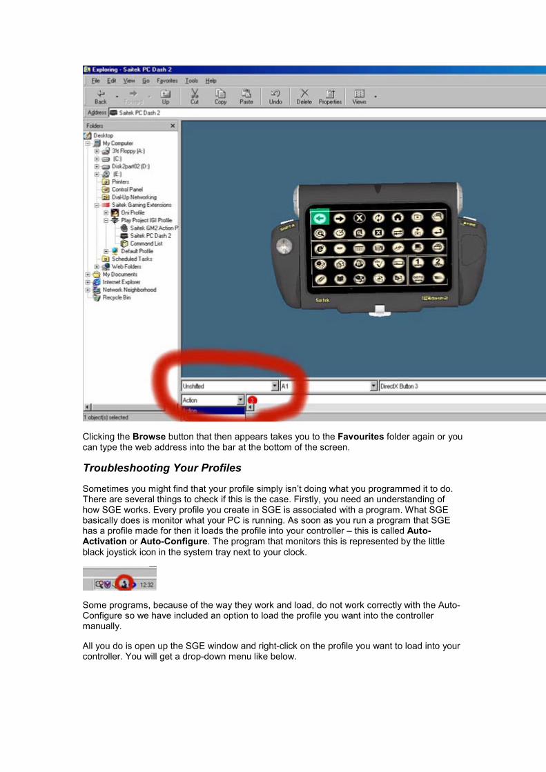
Clicking the Browse button that then appears takes you to the Favourites folder again or youcan type the web address into the bar at the bottom of the screen.
Troubleshooting Your Profiles
Sometimes you might find that your profile simply isn’t doing what you programmed it to do.There are several things to check if this is the case. Firstly, you need an understanding ofhow SGE works. Every profile you create in SGE is associated with a program. What SGEbasically does is monitor what your PC is running. As soon as you run a program that SGEhas a profile made for then it loads the profile into your controller – this is called Auto-Activation or Auto-Configure. The program that monitors this is represented by the littleblack joystick icon in the system tray next to your clock.
Some programs, because of the way they work and load, do not work correctly with the Auto-Configure so we have included an option to load the profile you want into the controllermanually.
All you do is open up the SGE window and right-click on the profile you want to load into yourcontroller. You will get a drop-down menu like below.
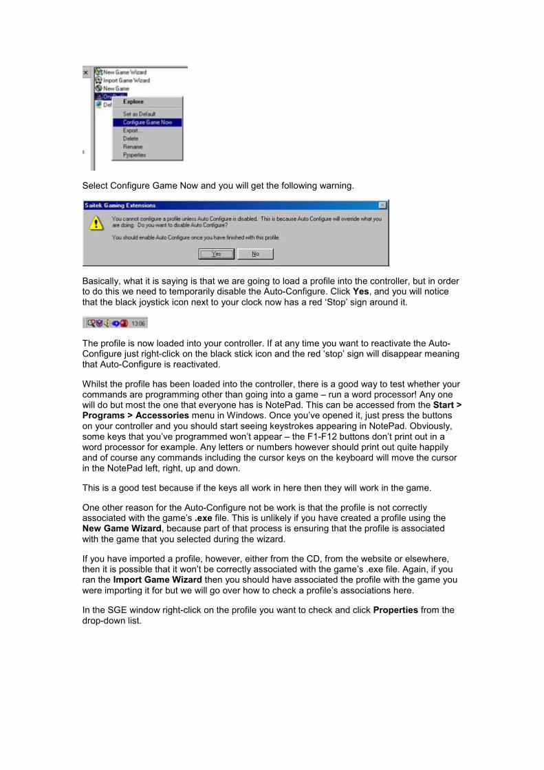
Select Configure Game Now and you will get the following warning.
Basically, what it is saying is that we are going to load a profile into the controller, but in orderto do this we need to temporarily disable the Auto-Configure. Click Yes, and you will noticethat the black joystick icon next to your clock now has a red ‘Stop’ sign around it.
The profile is now loaded into your controller. If at any time you want to reactivate the Auto-Configure just right-click on the black stick icon and the red ‘stop’ sign will disappear meaningthat Auto-Configure is reactivated.
Whilst the profile has been loaded into the controller, there is a good way to test whether yourcommands are programming other than going into a game – run a word processor! Any onewill do but most the one that everyone has is NotePad. This can be accessed from the Start >Programs > Accessories menu in Windows. Once you’ve opened it, just press the buttonson your controller and you should start seeing keystrokes appearing in NotePad. Obviously,some keys that you’ve programmed won’t appear – the F1-F12 buttons don’t print out in aword processor for example. Any letters or numbers however should print out quite happilyand of course any commands including the cursor keys on the keyboard will move the cursorin the NotePad left, right, up and down.
This is a good test because if the keys all work in here then they will work in the game.
One other reason for the Auto-Configure not be work is that the profile is not correctlyassociated with the game’s .exe file. This is unlikely if you have created a profile using theNew Game Wizard, because part of that process is ensuring that the profile is associatedwith the game that you selected during the wizard.
If you have imported a profile, however, either from the CD, from the website or elsewhere,then it is possible that it won’t be correctly associated with the game’s .exe file. Again, if youran the Import Game Wizard then you should have associated the profile with the game youwere importing it for but we will go over how to check a profile’s associations here.
In the SGE window right-click on the profile you want to check and click Properties from thedrop-down list.

You will see the following window.
The Target window is where we need to be looking. It needs to list the correct location of thegame’s .exe file on your hard drive. In the example above you can see that the game we usedwhen creating our profile in the basic section of the manual, Oni, is installed in theC:\Program Files\Oni directory. If this was incorrect or if it said nothing in the Target boxthen we would need to click Find Target and point the profile to the correct location of the.exe file.
Click Open and then Apply and this will ensure that the profile is now correctly associatedwith the profile.
Another reason for the profile to not be working correctly is if you have created more than oneprofile for the same game. If you have done this then one of the profiles will be slightly greyedout as seen in the example below.

The profile whose icon is still bold is currently set as the ‘default profile’, which means that itoverrides the other profile and is currently the only one that will load into the controller whenyou run the game. To make the greyed-out profile your controller’s default, just right-click on itand choose the Set As Default option from the drop-down list
That should cover any possible problems you might have with your profiles under SGE.
Enjoy your gaming!