
Guide to Dual Flight Operations - National Weather … html/Guide to Dual Flight...Guide to Dual...
22
Guide to Dual Flight Operations Preparing & Releasing a Dual Flight Bar Vaisala RS92-NGP ® Sippican B2 ® Attachment C Prepared by Sterling Field Support Center Updated April 6, 2012 U.S. DEPARTMENT OF COMMERCE National Oceanic and Atmospheric Administration National Weather Service/Office of Operational Systems Field Systems Operations Center/Observing Systems Branch
Transcript of Guide to Dual Flight Operations - National Weather … html/Guide to Dual Flight...Guide to Dual...
Guide to Dual Flight Operations Preparing & Releasing a Dual Flight Bar
Vaisala RS92-NGP® Sippican B2®
Attachment C
Prepared by
Sterling Field Support Center
Updated April 6, 2012
U.S. DEPARTMENT OF COMMERCE
National Oceanic and Atmospheric Administration
National Weather Service/Office of Operational Systems
Field Systems Operations Center/Observing Systems Branch

Table of Contents
List of Figures ............................................................................................................................... iii
ACRONYMS AND ABBREVIATIONS .................................................................................... iv
1.0 Introduction ........................................................................................................................ 5
2.0 Procedures .......................................................................................................................... 5
2.1 Equipment Warm-Up ................................................................................................................. 6
2.2 Balloon Inflation and Train Assembly ...................................................................................... 7
2.3 Radiosonde Preparation ........................................................................................................... 12
2.4 Ground Equipment Preparation Procedures ......................................................................... 14
2.5 Release Site Processes ............................................................................................................... 16
2.6 In-Flight Procedures ................................................................................................................. 20
2.7 Archiving & Post-Flight Test Activities .................................................................................. 21
NWS Sterling Field Support Center ......................................................................................... 22

iii
List of Figures
Figure 1. NOAA Security Warning Window ............................................................................. 6
Figure 2. RWS Action Selection Window ................................................................................... 6 Figure 3. RWS Windows after selecting "Run a Live Flight" .................................................. 7 Figure 4. Observer tying top and bottom parachutes together ................................................ 9 Figure 5. Knot joining top and bottom parachutes ................................................................... 9 Figure 6. Tying flight train to flight bar ................................................................................... 10
Figure 7. Knot connecting flight train and flight bar .............................................................. 10 Figure 8. Completed flight train ................................................................................................ 11 Figure 9. Schematic of completed flight train .......................................................................... 12 Figure 10. Vaisala RS92-NGP on Frequency Setting Device (FSD) ....................................... 13
Figure 11. Plugging in the RS92-NGP battery ......................................................................... 14 Figure 12. Preparing the Sippican B2 battery.......................................................................... 14
Figure 13. RS92-NGP hanging from knotted loop on assembled flight bar .......................... 16 Figure 14. Sippican B2 tied to assembled flight bar ................................................................ 17
Figure 15. Completed flight bar with RS92-NGP and Sippican B2 radiosondes.................. 17 Figure 16. Preparing for balloon release with flight bar ......................................................... 18 Figure 17. Balloon passing overhead of observer with flight bar ........................................... 19
Figure 18. Release of flight bar .................................................................................................. 19

iv
ACRONYMS AND ABBREVIATIONS
TERMS DEFINITION
MicroART Microcomputer Automatic Radio-theodolite
BILS Balloon Inflation Launch Shelter
CDU Control Display Unit
DCA Data Control Assembly
FSD Frequency Setting Device
GPS Global Positioning System
hPa. Hectopascal
IF Intermediate Frequency
KHz Kilohertz
LOS Line-Of-Sight
Mb Millibar
PSI Pounds Per Square Inch
IB Inflation Building
MHz Megahertz
MSL Mean Sea Level
NCDC National Climatic Data Center
NEC National Electrical Code
NFPA National Fire Protection Association
NOTAM Notice to Airman
PITS Protocol Interface Tests Suite
RF Radio Frequency
RRS Radiosonde Replacement System
RSOIS Radiosonde Surface Observing Instrument System
RTS Radiosonde Test Stand
RWS RRS Workstation
SDM Station Duty Manual
SFSC Sterling Field Support Center
SPS Signal Processing System
SPSS Statistical Package for the Social Sciences
TRS Telemetry Receiving System
UHF Ultra High Frequency
UPS Uninterruptible Power Supply
UTC Coordinated Universal Time
WMO World Meteorological Organization
5
1.0 Introduction
The Upper Air Data Continuity Study (DCS) is useful for investigating the relationship between
climate variation and change due to measurement error. To replace the antiquated
Microcomputer Automatic Radio-theodolite (MicroART), a system that has been in operation
since the late 1980s, new Global Positioning System (GPS) radiosondes have been introduced.
The National Weather Service (NWS) upper air network has witnessed a significant impact on
operations from the implementation of the new GPS radiosondes due to sensor changes for
temperature, pressure and relative humidity measurements. Because these have differing
characteristics than other current radiosondes, the DCS is pertinent in assessing the sensors in a
variety of climatic and meteorological conditions.
The DCS flight configuration will consist of flying two radiosondes on the same balloon during
the 00z and 12z synoptic windows once a week. The day that flights will occur will be left up to
the site’s discretion; however, once DCS flights begin, the site will continue with that scheduled
day. It is suggested that the site conduct operations on a Tuesday, Wednesday or Thursday in
order to alleviate issues with holidays or vacations that often occur on a Monday or Friday.
These flights must be conducted as precisely as possible in order to accurately assess the sensors’
behavior. The purpose of this document is to guide observers through the steps to properly
assemble and release a dual flight bar in order to complete an accurate and successful flight using
the Vaisala RS92-NGP and Sippican B2 radiosondes.
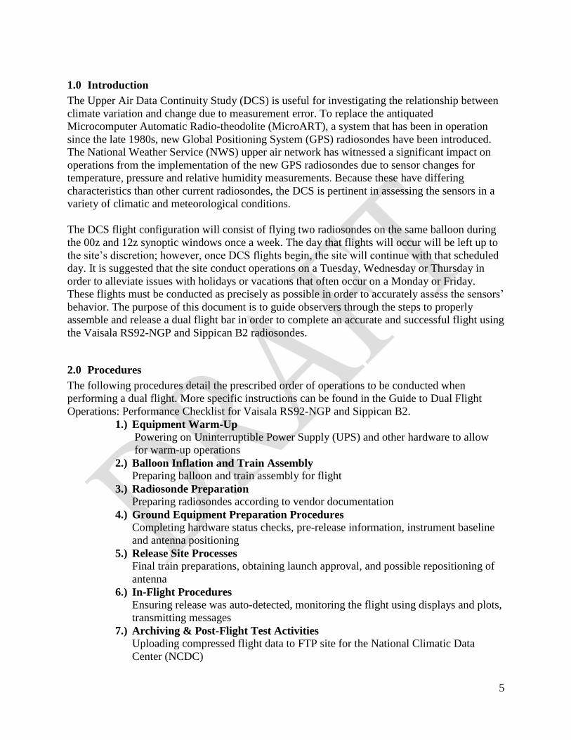
2.0 Procedures
The following procedures detail the prescribed order of operations to be conducted when
performing a dual flight. More specific instructions can be found in the Guide to Dual Flight
Operations: Performance Checklist for Vaisala RS92-NGP and Sippican B2.
1.) Equipment Warm-Up
Powering on Uninterruptible Power Supply (UPS) and other hardware to allow
for warm-up operations
2.) Balloon Inflation and Train Assembly
Preparing balloon and train assembly for flight
3.) Radiosonde Preparation
Preparing radiosondes according to vendor documentation
4.) Ground Equipment Preparation Procedures
Completing hardware status checks, pre-release information, instrument baseline
and antenna positioning
5.) Release Site Processes
Final train preparations, obtaining launch approval, and possible repositioning of
antenna
6.) In-Flight Procedures
Ensuring release was auto-detected, monitoring the flight using displays and plots,
transmitting messages
7.) Archiving & Post-Flight Test Activities
Uploading compressed flight data to FTP site for the National Climatic Data
Center (NCDC)
2.1 Equipment Warm-Up
The observer should begin preparing for a dual flight at least 45 minutes in advance in order to
allow adequate time for the workstations and tracking systems to warm-up. Specifically with the
TRS, warm-up operations could take 30 minutes, especially in colder temperatures. This also
provides the observer with more time to troubleshoot the hardware in the case a problem arises.
Turn on both the RRS Workstation (RWS) and MicroART computer. Log into the
RWS workstation using your individual Username and Password.
Ensure the GPS repeater is turned on.
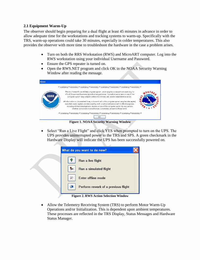
Open the RWS.NET program and click OK in the NOAA Security Warning
Window after reading the message.
Figure 1. NOAA Security Warning Window
Select “Run a Live Flight” and click YES when prompted to turn on the UPS. The
UPS provides uninterrupted power to the TRS and SPS. A green checkmark in the
Hardware Display will indicate the UPS has been successfully powered on.
Figure 2. RWS Action Selection Window
Allow the Telemetry Receiving System (TRS) to perform Motor Warm-Up
Operations and/or Initialization. This is dependent upon ambient temperatures.
These processes are reflected in the TRS Display, Status Messages and Hardware
Status Manager.
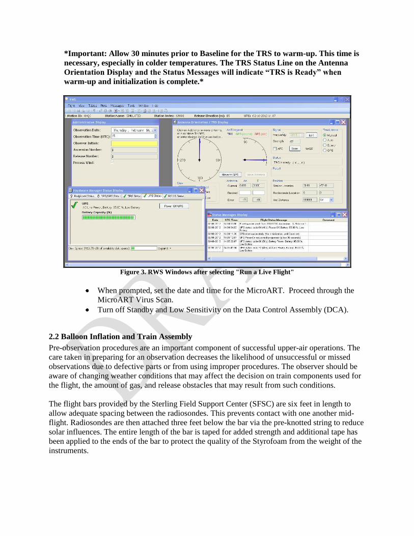
*Important: Allow 30 minutes prior to Baseline for the TRS to warm-up. This time is
necessary, especially in colder temperatures. The TRS Status Line on the Antenna
Orientation Display and the Status Messages will indicate “TRS is Ready” when
warm-up and initialization is complete.*
Figure 3. RWS Windows after selecting "Run a Live Flight"
When prompted, set the date and time for the MicroART. Proceed through the
MicroART Virus Scan.
Turn off Standby and Low Sensitivity on the Data Control Assembly (DCA).
2.2 Balloon Inflation and Train Assembly
Pre-observation procedures are an important component of successful upper-air operations. The
care taken in preparing for an observation decreases the likelihood of unsuccessful or missed
observations due to defective parts or from using improper procedures. The observer should be
aware of changing weather conditions that may affect the decision on train components used for
the flight, the amount of gas, and release obstacles that may result from such conditions.
The flight bars provided by the Sterling Field Support Center (SFSC) are six feet in length to
allow adequate spacing between the radiosondes. This prevents contact with one another mid-
flight. Radiosondes are then attached three feet below the bar via the pre-knotted string to reduce
solar influences. The entire length of the bar is taped for added strength and additional tape has
been applied to the ends of the bar to protect the quality of the Styrofoam from the weight of the
instruments.
Begin inflating an HM-32 1200 gram balloon provided by the Sterling Field
Support Center (SFSC)
Determine the additional weight needed for the dual flight depending on the
present weather conditions and those expected at the time of release. The
following chart can assist in determining this weight based on the prevailing
weather type and intensity:
Precipitation Frozen Precipitation
Intensity Additional Weight (g) Intensity Additional Weight (g)
Light Rain 1100-1300 g Light Frozen 1200-1400 g
Moderate Rain 1300-1500 g Moderate Frozen 1400-1500 g
Heavy Rain 1500-1800 g Heavy Frozen 1700-1900 g
No Precipitation: 800-1000 g
* This table should only be used as a guideline for applying additional weight since
ranges are heavily dependent upon location, temperature variations, and balloon
manufacturing procedures. It is important to monitor the flight to ensure SFC-Term
ascent rates of 275-350 m/min are being achieved.*
For actual lift calculations, the following table lists the nominal weights for the
train assembly:
Components Weight (grams)
RS92-NGP Radiosonde 305
B2 Radiosonde 475
Spreader Bar Assemble 214
Parachutes (2) 150
Total 1144
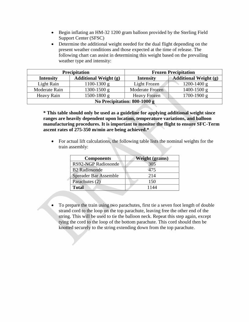
To prepare the train using two parachutes, first tie a seven foot length of double
strand cord to the loop on the top parachute, leaving free the other end of the
string. This will be used to tie the balloon neck. Repeat this step again, except
tying the cord to the loop of the bottom parachute. This cord should then be
knotted securely to the string extending down from the top parachute.
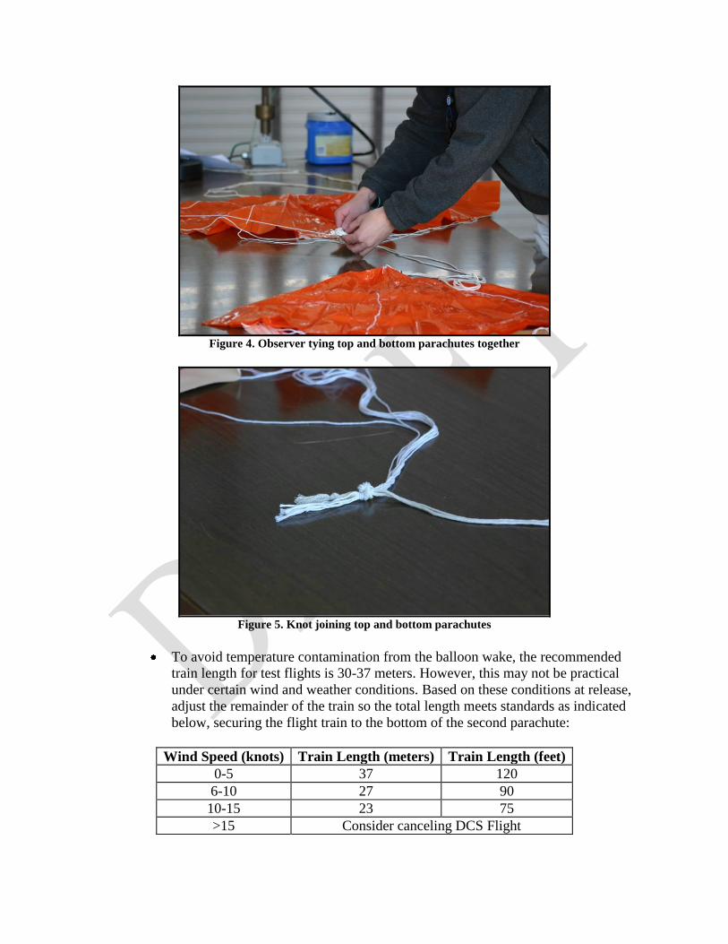
Figure 4. Observer tying top and bottom parachutes together
Figure 5. Knot joining top and bottom parachutes
To avoid temperature contamination from the balloon wake, the recommended
train length for test flights is 30-37 meters. However, this may not be practical
under certain wind and weather conditions. Based on these conditions at release,
adjust the remainder of the train so the total length meets standards as indicated
below, securing the flight train to the bottom of the second parachute:
Wind Speed (knots) Train Length (meters) Train Length (feet)
0-5 37 120
6-10 27 90
10-15 23 75
>15 Consider canceling DCS Flight
Note: The total train length (70-120 feet) is the distance extending from the balloon
neck to the top of the flight bar. It does not describe the length from the bottom of the
second parachute to the top of the flight bar.
*The minimum train length should not be less than that which the NWS considers
acceptable for operations (21 meters). Trains less than the prescribed length should
never be used since this increases the risk of the radiosonde being too close to the
radiation environment of the balloon or from encountering the balloon’s wake as it
ascends. Erroneous data may result from these occurrences. *
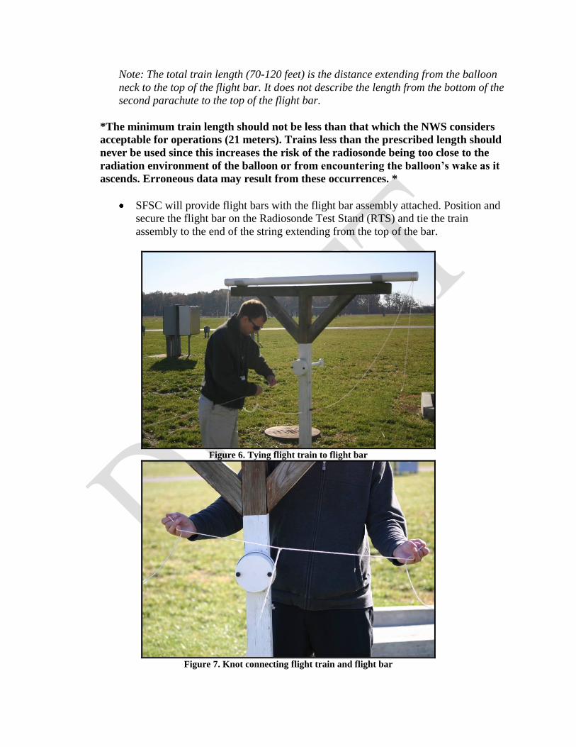
SFSC will provide flight bars with the flight bar assembly attached. Position and
secure the flight bar on the Radiosonde Test Stand (RTS) and tie the train
assembly to the end of the string extending from the top of the bar.
Figure 6. Tying flight train to flight bar
Figure 7. Knot connecting flight train and flight bar
When Applicable: Because the flight train is longer and larger in mass, two glow
sticks should be used for a nighttime dual release. Attach one glow stick to the
end of the second parachute with the small strings that extend from the knot. The
second glow stick should be tied to the bottom of the flight train where it is
connected to the flight bar.
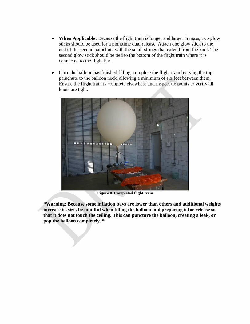
Once the balloon has finished filling, complete the flight train by tying the top
parachute to the balloon neck, allowing a minimum of six feet between them.
Ensure the flight train is complete elsewhere and inspect tie points to verify all
knots are tight.
Figure 8. Completed flight train
*Warning: Because some inflation bays are lower than others and additional weights
increase its size, be mindful when filling the balloon and preparing it for release so
that it does not touch the ceiling. This can puncture the balloon, creating a leak, or
pop the balloon completely. *

Figure 9. Schematic of completed flight train
2.3 Radiosonde Preparation
Using the provided radiosonde and battery preparation instructions and NWS standard
procedures, prepare the radiosondes for flight. It is pertinent that the instruments be handled
carefully so that contamination to the sensors by the observer can be alleviated. Mishandling the
unit could also comprise the integrity of the data during flight.
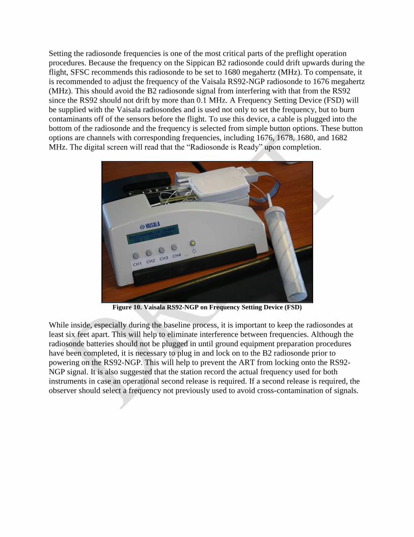
Setting the radiosonde frequencies is one of the most critical parts of the preflight operation
procedures. Because the frequency on the Sippican B2 radiosonde could drift upwards during the
flight, SFSC recommends this radiosonde to be set to 1680 megahertz (MHz). To compensate, it
is recommended to adjust the frequency of the Vaisala RS92-NGP radiosonde to 1676 megahertz
(MHz). This should avoid the B2 radiosonde signal from interfering with that from the RS92
since the RS92 should not drift by more than 0.1 MHz. A Frequency Setting Device (FSD) will
be supplied with the Vaisala radiosondes and is used not only to set the frequency, but to burn
contaminants off of the sensors before the flight. To use this device, a cable is plugged into the
bottom of the radiosonde and the frequency is selected from simple button options. These button
options are channels with corresponding frequencies, including 1676, 1678, 1680, and 1682
MHz. The digital screen will read that the “Radiosonde is Ready” upon completion.
Figure 10. Vaisala RS92-NGP on Frequency Setting Device (FSD)
While inside, especially during the baseline process, it is important to keep the radiosondes at
least six feet apart. This will help to eliminate interference between frequencies. Although the
radiosonde batteries should not be plugged in until ground equipment preparation procedures
have been completed, it is necessary to plug in and lock on to the B2 radiosonde prior to
powering on the RS92-NGP. This will help to prevent the ART from locking onto the RS92-
NGP signal. It is also suggested that the station record the actual frequency used for both
instruments in case an operational second release is required. If a second release is required, the
observer should select a frequency not previously used to avoid cross-contamination of signals.

Figure 11. Plugging in the RS92-NGP battery
Figure 12. Preparing the Sippican B2 battery
2.4 Ground Equipment Preparation Procedures
Once the flight train and radiosondes have been prepared, the ground equipment procedures must
be completed prior to releasing the balloon:
Position the TRS antenna within a few degrees of the baseline point using the
Antenna Display Window. Complete the Administrative and Equipment Displays
then click Next;
Position the ART antenna within a few degrees of the documented target antenna.
Turn the target antenna switch on and allow the antenna to lock on the target antenna
by pressing Far Auto;

From the ART Options Menu, select ART Observation. When prompted, complete
the Administrative Data and Flight Equipment Data screens;
In RWS, set the radiosonde frequency in the TRS Display after placing the TRS in
Manual Track Mode. This can be done by clicking Edit, entering the frequency,
clicking Set and turning AFC ON;
Complete the VIZ Radiosonde Data screen and insert the appropriate Calibration
Diskette into the drive hen prompted; and
At this time, complete the radiosonde procedures by preparing and activating
batteries.
*Ensure that the Sippican B2 and Vaisala RS92-NGP radiosondes are no closer
than six feet from one another during the baseline process. It is important to plug in
and lock on to the B2 radiosonde before plugging in the RS92-NGP. If this is not
completed, it is likely the ART will lock onto the RS92-NGP.*
Complete the Surface Observation Display and Surface Data screen in both RWS and
MicroART using the most recent surface observation. This should be completed no
more than 10 minutes prior to release. Confirm that batteries are plugged in before
beginning baseline.
Continue to the cross-check message screen in MicroART to review any
inconsistencies. Insert the Log Diskette and press enter when ready. Adjust the
Azimuth to the appropriate angle to prepare for baseline and acquire a radiosonde
signal. Check the AFC meter to ensure the transmitter signal is being received clearly.
Press Standby once this is complete.
In RWS, click Next from the Surface Observation Display to begin the baseline
process. In MicroART, press Enter to begin the baseline check. Once the readings
become stable, compare the instrument’s readings against the surface conditions
entered.
*Once the Baseline Display window has appeared and started populating, wait at
least five minutes before accepting. Time is needed for the sensors to stabilize and
for a proper pressure correction to be calculated. Baseline MUST be accepted
before releasing the balloon.*
Note: Ensure pressure sensor has stabilized prior to accepting baseline. The battery and
pressure sensor must warm-up. If the pressure sensor is not warmed up, pressure
discrepancy may create height errors.
If the pressure discrepancy is within ± 3 hPa for the Vaisala RS92-NGP radiosonde
and the temperature and relative humidity values look reasonable, click Accept. Do
not complete baseline without GPS. “Waiting for Release” will then be displayed on
the RWS screen.
For the MicroART, press F10 to complete baseline. After the baselining tests are
complete, accept the radiosonde by clicking enter if the pressure discrepancy is within
± 5 hPa. The Antenna Lock screen will display ***RADIOSONDE READY FOR
RELEASE***.
Before proceeding to the release site, put the TRS in Manual Track Mode and direct
the Azimuth/Elevation to where the radiosonde is expected to travel. For the ART,
ensure that Standby is illuminated and move the Azimuth/Elevation to where the
radiosonde is expected to travel. Confirm that the Track Mode for the ART is set to
Manual.
The TRS is 180 degrees out from the wind direction. Because they can easily be
confused with the ART, the following chart lists pressure discrepancy thresholds and
orientation of the antenna before and during the flight:
Pressure Discrepancy Antenna-North
TRS Vaisala RS92-NGP: ± 3 hPa Azimuth of 0 degrees
MicroART Sippican B2: ± 5 hPa Azimuth of 180 degrees
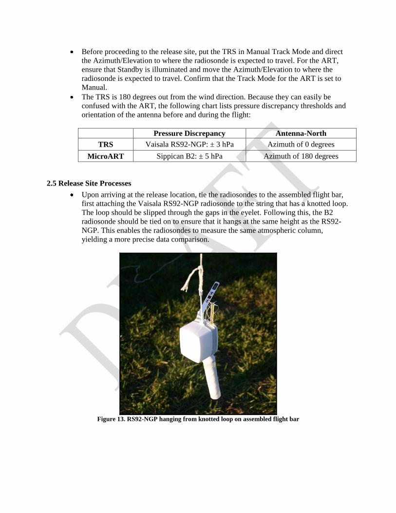
2.5 Release Site Processes
Upon arriving at the release location, tie the radiosondes to the assembled flight bar,
first attaching the Vaisala RS92-NGP radiosonde to the string that has a knotted loop.
The loop should be slipped through the gaps in the eyelet. Following this, the B2
radiosonde should be tied on to ensure that it hangs at the same height as the RS92-
NGP. This enables the radiosondes to measure the same atmospheric column,
yielding a more precise data comparison.
Figure 13. RS92-NGP hanging from knotted loop on assembled flight bar

Figure 14. Sippican B2 tied to assembled flight bar
Figure 15. Completed flight bar with RS92-NGP and Sippican B2 radiosondes
Visually inspect the release zone and the anticipated path of flight for any obstacles or
dangers. Check the flight train’s integrity and ensure radiosondes are secure on the
flight bar.
If within five nautical miles of an airport, call the airport control tower and request
approval to release the balloon.
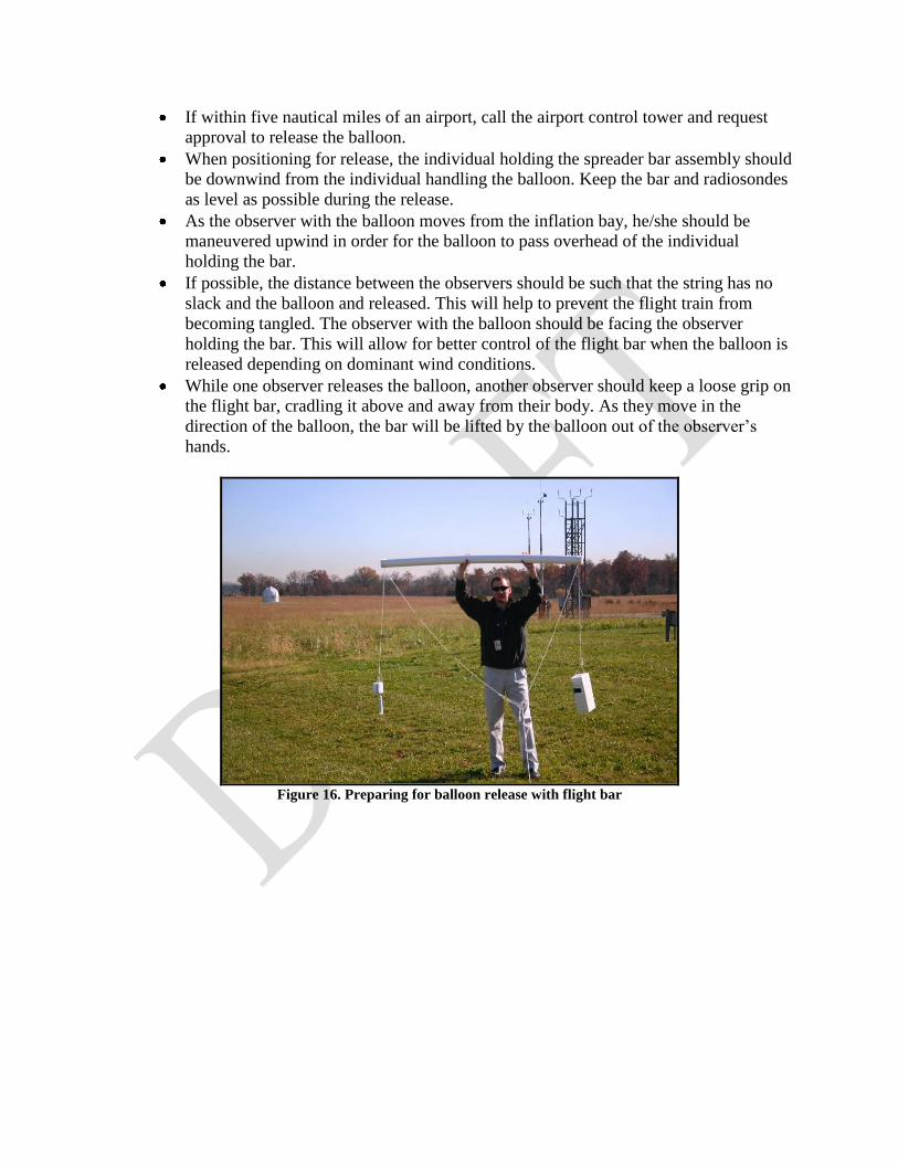
When positioning for release, the individual holding the spreader bar assembly should
be downwind from the individual handling the balloon. Keep the bar and radiosondes
as level as possible during the release.
As the observer with the balloon moves from the inflation bay, he/she should be
maneuvered upwind in order for the balloon to pass overhead of the individual
holding the bar.
If possible, the distance between the observers should be such that the string has no
slack and the balloon and released. This will help to prevent the flight train from
becoming tangled. The observer with the balloon should be facing the observer
holding the bar. This will allow for better control of the flight bar when the balloon is
released depending on dominant wind conditions.
While one observer releases the balloon, another observer should keep a loose grip on
the flight bar, cradling it above and away from their body. As they move in the
direction of the balloon, the bar will be lifted by the balloon out of the observer’s
hands.
Figure 16. Preparing for balloon release with flight bar

Figure 17. Balloon passing overhead of observer with flight bar
Figure 18. Release of flight bar
Once the balloon is released, the observer should then hit the release pulse as the
other observer lets go of the bar. The ART timed release may be used, but a best
effort should be made to time when the spreader bar will begin its ascent.
After release, the observer can use the TRS remote Control Display Unit (CDU) to
verify the frequency has not shifted for the Vaisala RS92-NGP. Double check to
ensure the antenna is positioned to the appropriate azimuth and elevation and that
AFC is on. After returning to the workstation, check to make sure release was
detected. RWS should automatically detect release. Update the Surface Observation
and release time as necessary.
Upon returning to the RWS workstation, verify the TRS signal strength is acceptable.
If GPS is being received, place the Antenna into Search mode in the Antenna
Orientation Display. Auto track mode will automatically be selected once the TRS
has detected the strongest signal. The TRS can also be pointed towards the balloon in
the Azimuth/Elevation window by inputting values and clicking Move Antenna or

Move to GPS. Do not click Move to GPS if GPS data is unavailable as this may
cause the software to freeze.
To verify that release has been detected and logged correctly, check the first pressure
data point below the red line in the Received PTU Tabular Display. This point should
have a pressure equal or less than the release pressure shown in the Surface
Observation at release. Check the Geopotential Height and ensure it increases with
time.
For the Sippican B2, open the ART remote release panel and turn up the speaker
volume to check for a clean signal. Initiate release, then adjust the position to acquire
and maintain a lock to the radiosonde. Turn Auto Track and AFC On. After returning
to the PC, enter the time the antenna locked onto the radiosonde and delete position
data up to the point lock-on occurred. Verify the Surface Observation screen as
necessary.
Monitor the B2 signal strength and adjust the Azimuth and Elevation if necessary to
maintain a lock onto the radiosonde. The audio should be utilized to verify accurate
instrument tones and to check for interference or signal loss.
2.6 In-Flight Procedures
During the flight, to the extent possible, site personnel will monitor the flight for potential
problems and ensure the validity of the test. Any problems should be documented and the site
should notify the RRS Help Line. Since the RWS system acts as the operational system, it is
imperative the flight be quality controlled in an operationally acceptable manner. With regard to
the MicroART flight, the operator may quality control the data if time permits. However, it is not
necessary since office operations will always take precedence.
Monitoring the flights using displays and plots can assist in ensuring the flight is successful. A
variety of parameters can be plotted, including temperature, winds and relative humidity. This
data should be quality controlled throughout the flight in order for the observer to determine if
edits are necessary, especially in RWS. Periodically checking the Check and Status Messages
and incoming meteorological data also assists the observer in verifying ascent rates are realistic.
These averages should be approximately 5 meter/sec or 275-350 meter/min. Furthermore,
confirm RADAT and Coded Messages appear to be correct, especially before message
transmission is initiated.
Upon completion of the flight, both RWS and MicroART will detect termination. Transmit all
remaining messages before closing each program. In RWS, the flight must be closed before the
observer can exit RWS. The UPS should be turned off when prompted. Although the flight has
been closed, it can still be opened in Rework if additional edits are desired. For MicroART, exit
the ART Observation option by typing EXIT at the ?> prompt. Remove the Log diskette from
the diskette drive and insert the Store diskette currently in use.

2.7 Archiving & Post-Flight Test Activities
After each test flight, the data from both systems will be archived in a manner consistent with
established site procedures. Personnel will make every effort to complete the Data Continuity
Input Form immediately after the flight. If this is not possible, it should be completed by the end
of the current shift. Additionally, when the B29 form is completed, the remark “DCS flight”
should be noted in the Remarks section. Other remarks may be entered at the discretion of upper
air personnel. The site should contact SFSC if a significant event occurred which may have a
negative impact on the DCS flight.

NWS Sterling Field Support Center
The NWS Sterling Field Support Center serves to provide operational assistance to National
Weather Service field personnel with questions that pertain with the operation of a new RWS
system, including pre-flight and flight assistance during synoptic soundings. The SFSC
assists users in order to ensure continuity in understanding of the RWS system and quality
data collection among all operating deployment sites.
Hours of Operation Contact
M-F 10:00-02:00 UTC (301) 713-9800 (703) 661-1293


