
GUIDE TO CBN & PCD TURNING INSERTS
74
B000 B026 NEG CBN NP-CNGA 4 3 1 GA4 80° CN H K S CBN MBC010 MBC020 BC8020 BC8105 BC8110 BC8120 BC8130 MB810 MB8025 MB825 MB835 MB710 MB730 MB4020 MBS140 NP-CNGA431-GA4 NP-CNGA120404GA4 .016 a a ss C006 ─009 E021 E024 H006 ─008 NP-CNGA432-GA4 NP-CNGA120408GA4 .031 a a ss NP-CNGA433-GA4 NP-CNGA120412GA4 .047 a s ss NP-CNGA431-GS4 NP-CNGA120404GS4 .016 a s NP-CNGA432-GS4 NP-CNGA120408GS4 .031 a s NP-CNGA433-GS4 NP-CNGA120412GS4 .047 a s NP-CNGA431-GN4 NP-CNGA120404GN4 .016 s NP-CNGA432-GN4 NP-CNGA120408GN4 .031 s NP-CNGA433-GN4 NP-CNGA120412GN4 .047 s NP-CNGA431-GH4 NP-CNGA120404GH4 .016 a aa NP-CNGA432-GH4 NP-CNGA120408GH4 .031 a aa NP-CNGA433-GH4 NP-CNGA120412GH4 .047 a aa NP-CNGA431-FS4 NP-CNGA120404FS4 .016 s a ss NP-CNGA432-FS4 NP-CNGA120408FS4 .031 s a ss NP-CNGA433-FS4 NP-CNGA120412FS4 .047 s a ss NP-CNGA431-TA4 NP-CNGA120404TA4 .016 ss ss NP-CNGA432-TA4 NP-CNGA120408TA4 .031 ss ss NP-CNGA433-TA4 NP-CNGA120412TA4 .047 ss ss NP-CNGA431-TS4 NP-CNGA120404TS4 .016 s NP-CNGA432-TS4 NP-CNGA120408TS4 .031 s NP-CNGA433-TS4 NP-CNGA120412TS4 .047 s NP-CNGA431-TH4 NP-CNGA120404TH4 .016 a s NP-CNGA432-TH4 NP-CNGA120408TH4 .031 a s NP-CNGA433-TH4 NP-CNGA120412TH4 .047 a s NP-CNGA431-FSWS4 NP-CNGA120404FSWS4 .016 a a a C006 ─009 E021 E024 H006 ─008 NP-CNGA432-FSWS4 NP-CNGA120408FSWS4 .031 a a a NP-CNGA433-FSWS4 NP-CNGA120412FSWS4 .047 a a a NP-CNGA431-GAWS4 NP-CNGA120404GAWS4 .016 s ss NP-CNGA432-GAWS4 NP-CNGA120408GAWS4 .031 a ss NP-CNGA433-GAWS4 NP-CNGA120412GAWS4 .047 a ss NP-CNGA431-GSWS4 NP-CNGA120404GSWS4 .016 a s NP-CNGA432-GSWS4 NP-CNGA120408GSWS4 .031 a s NP-CNGA433-GSWS4 NP-CNGA120412GSWS4 .047 a s BF-CNGG431-TA4 BF-CNGG120404TA4 .016 s C006 ─009 E021 E024 H006 ─008 BF-CNGG432-TA4 BF-CNGG120408TA4 .031 s BF-CNGG433-TA4 BF-CNGG120412TA4 .047 s * 1 * 1 * 1 * 1 * 1 * 1 * 1 * 1 * 1 = B054 CBN RTG POSI 5º 6º H K S CBN MB825 IC L17 S D4 RTG05A RTG05A s .197 .138 .295 .098 ─ RTG06A RTG06A s .236 .138 .295 .138 RTG07A RTG07A s .276 .197 .433 .138 RTG08A RTG08A s .315 .197 .433 .177 RTG10A RTG10A s .394 .256 .551 .217 IC D4 S L17 GUIDE TO CBN & PCD TURNING INSERTS Section organization zOrganized according to turning insert shape. (Refer to the index on the next page.) xInserts are arranged in order of : · Negative inserts (with hole|without hole) · Positive inserts (with hole|without hole) GRADE APPLICATION RECOMMENDED FOR EACH WORK MATERIAL Stable Cutting General Cutting Unstable Cutting FIGURE SHOWING INSERT GEOMETRY SHAPE & ANGLE MARK INDICATION OF NEGATIVE/POSITIVE TYPE INSERT DIMENSIONS INSERT GRADES STOCK STATUS TITLE OF PRODUCT ACCORDING TO THE INSERT TYPE PRODUCT SECTION LEGEND FOR STOCK STATUS MARK APPLICABLE HOLDER PAGE PHOTO OF INSERT INSERT CORNER RADIUS INSERT NUMBER PRODUCT NAME aTo Order: Please specify insert number and grade. cutting conditions suitable for each work materials are shown as a general guide to select grade. Dimensions are detailed in the "Dimensions" column. is shown on the left hand page of each double-page spread. indicates reference pages for details of applicable holders. CBN & PCD TURNING INSERTS TYPE INSERTS WITH HOLE Size Thickness Corner Radius Honing & Wiper * Please refer to page B002. Cutting Conditions : Stable Cutting General Cutting Unstable Cutting Work Material Shape Order Number (ISO) Number Corner Radius RE (inch) NEW PETIT CUT NEW PETIT CUT (With Wiper) NEW PETIT CUT (With breaker) Coated CBN * 1 Please refer to page B017 before using the wiper insert. Hardened Materials Cast Iron Heat-resistant Alloy, Titanium Alloy Sintered Alloy Solid CBN WITH HOLE CBN TURNING INSERTS [NEGATIVE] a : Inventory maintained. s: Inventory maintained in Japan. <1 insert in one case> Applicable Holder Page CBN & PCD TURNING INSERTS CBN TURNING INSERTS [POSITIVE] a : Inventory maintained. s: Inventory maintained in Japan. <1 insert in one case> Hardened Materials Cast Iron Heat-resistant Alloy, Titanium Alloy TYPE INSERTS WITHOUT HOLE Work Material Shape Order Number (ISO) Number Dimensions (inch) Cutting Conditions : Stable Cutting General Cutting Unstable Cutting Applicable Holder Page WITHOUT HOLE
Transcript of GUIDE TO CBN & PCD TURNING INSERTS

B000
B026
NEG
CBN
NP-CNGA 4 3 1 GA480° CNHKS
CBN
MB
C01
0M
BC
020
BC
8020
BC
8105
BC
8110
BC
8120
BC
8130
MB
810
MB
8025
MB
825
MB
835
MB
710
MB
730
MB
4020
MB
S140
NP-CNGA431-GA4 NP-CNGA120404GA4 .016 a a s s
C006─009E021E024H006─008
NP-CNGA432-GA4 NP-CNGA120408GA4 .031 a a s s
NP-CNGA433-GA4 NP-CNGA120412GA4 .047 a s s s
NP-CNGA431-GS4 NP-CNGA120404GS4 .016 a s
NP-CNGA432-GS4 NP-CNGA120408GS4 .031 a s
NP-CNGA433-GS4 NP-CNGA120412GS4 .047 a s
NP-CNGA431-GN4 NP-CNGA120404GN4 .016 s
NP-CNGA432-GN4 NP-CNGA120408GN4 .031 s
NP-CNGA433-GN4 NP-CNGA120412GN4 .047 s
NP-CNGA431-GH4 NP-CNGA120404GH4 .016 a a a
NP-CNGA432-GH4 NP-CNGA120408GH4 .031 a a a
NP-CNGA433-GH4 NP-CNGA120412GH4 .047 a a a
NP-CNGA431-FS4 NP-CNGA120404FS4 .016 s a s s
NP-CNGA432-FS4 NP-CNGA120408FS4 .031 s a s s
NP-CNGA433-FS4 NP-CNGA120412FS4 .047 s a s s
NP-CNGA431-TA4 NP-CNGA120404TA4 .016 s s s s
NP-CNGA432-TA4 NP-CNGA120408TA4 .031 s s s s
NP-CNGA433-TA4 NP-CNGA120412TA4 .047 s s s s
NP-CNGA431-TS4 NP-CNGA120404TS4 .016 s
NP-CNGA432-TS4 NP-CNGA120408TS4 .031 s
NP-CNGA433-TS4 NP-CNGA120412TS4 .047 s
NP-CNGA431-TH4 NP-CNGA120404TH4 .016 a s
NP-CNGA432-TH4 NP-CNGA120408TH4 .031 a s
NP-CNGA433-TH4 NP-CNGA120412TH4 .047 a s
NP-CNGA431-FSWS4 NP-CNGA120404FSWS4 .016 a a a
C006─009E021E024H006─008
NP-CNGA432-FSWS4 NP-CNGA120408FSWS4 .031 a a a
NP-CNGA433-FSWS4 NP-CNGA120412FSWS4 .047 a a a
NP-CNGA431-GAWS4 NP-CNGA120404GAWS4 .016 s s s
NP-CNGA432-GAWS4 NP-CNGA120408GAWS4 .031 a s s
NP-CNGA433-GAWS4 NP-CNGA120412GAWS4 .047 a s s
NP-CNGA431-GSWS4 NP-CNGA120404GSWS4 .016 a s
NP-CNGA432-GSWS4 NP-CNGA120408GSWS4 .031 a s
NP-CNGA433-GSWS4 NP-CNGA120412GSWS4 .047 a s
BF-CNGG431-TA4 BF-CNGG120404TA4 .016 s C006─009E021E024H006─008
BF-CNGG432-TA4 BF-CNGG120408TA4 .031 s
BF-CNGG433-TA4 BF-CNGG120412TA4 .047 s
*1
*1
*1
*1
*1
*1
*1
*1
*1
=
B054
CBNRTG
POSI 5º6º
HKS
CBN
MB
825 IC L17 S D4
RTG05A RTG05A s .197 .138 .295 .098
─
RTG06A RTG06A s .236 .138 .295 .138RTG07A RTG07A s .276 .197 .433 .138RTG08A RTG08A s .315 .197 .433 .177RTG10A RTG10A s .394 .256 .551 .217
IC
D4
SL17
GUIDE TO CBN & PCD TURNING INSERTSSection organization
zOrganized according to turning insert shape.(Refer to the index on the next page.)
xInserts are arranged in order of :·Negative inserts (with hole|without hole)·Positive inserts (with hole|without hole)
GRADE APPLICATION RECOMMENDED FOR EACH WORK MATERIAL
Stable Cutting General Cutting Unstable Cutting
FIGURE SHOWING INSERT GEOMETRY
SHAPE & ANGLE MARK
INDICATION OF NEGATIVE/POSITIVE TYPE INSERT DIMENSIONS
INSERT GRADESSTOCK STATUS
TITLE OF PRODUCT ACCORDING TO THE INSERT TYPE
PRODUCT SECTION
LEGEND FOR STOCK STATUS MARK APPLICABLE HOLDER PAGE
PHOTO OF INSERT INSERT CORNER RADIUS
INSERT NUMBERPRODUCT NAME
aTo Order: Please specify insert number and grade.
cutting conditions suitable for each work materials are shown as a general guide to select grade. Dimensions are detailed in the "Dimensions" column.
is shown on the left hand page of each double-page spread.
indicates reference pages for details of applicable holders.
CBN
& PC
D TU
RNIN
G IN
SERT
S
TYPE INSERTSWITH HOLE Size Thickness Corner Radius Honing & Wiper
*Please refer to page B002.
Cutting Conditions : Stable Cutting General Cutting Unstable Cutting
Work Material
Shape Order Number (ISO) Number
Corner Radius
RE
(inch)
NEW PETIT CUT
NEW PETIT CUT(With Wiper)
NEW PETIT CUT
(With breaker)
Coated CBN
*1 Please refer to page B017 before using the wiper insert.
Hardened MaterialsCast IronHeat-resistant Alloy, Titanium AlloySintered Alloy
Solid CBN
WITH HOLE
CBN TURNING INSERTS [NEGATIVE]
a : Inventory maintained. s : Inventory maintained in Japan. <1 insert in one case>
App
licab
le
Hol
der P
age
CBN
& PC
D TU
RNIN
G IN
SERT
S
CBN TURNING INSERTS [POSITIVE]
a : Inventory maintained. s : Inventory maintained in Japan. <1 insert in one case>
Hardened MaterialsCast IronHeat-resistant Alloy, Titanium Alloy
TYPE INSERTS WITHOUT HOLE
Work Material
Shape Order Number (ISO) Number
Dimensions (inch)
Cutting Conditions : Stable Cutting General Cutting Unstable Cutting
App
licab
le
Hol
der P
age
WITHOUT HOLE

B001
TURNING
INSERT STANDARDSINSERT GRADES
INDENTIFICATION ...................................................................... B002COATED CBN-SERIES FOR HARDENED STEEL TURNING ... B006PCD GRADE MD220 (SINTERED DIAMOND) ........................... B018CLASSIFICATION OF CBN & PCD INSERTS ............................ B020
STANDARD OF CBN TURNING INSERTSa NEGATIVE INSERTS WITH HOLE
CNppTYPE ...RHOMBIC 80° ............. B026DNppTYPE ...RHOMBIC 55° ............. B029SNppTYPE ...SQUARE 90° .............. B033TNppTYPE ...TRIANGULAR 60° ........ B034VNppTYPE ...RHOMBIC 35° ............. B036WNppTYPE ...TRIGON 80° ............... B038
a NEGATIVE INSERTS WITHOUT HOLECNppTYPE ...RHOMBIC 80° ............. B039DNppTYPE ...RHOMBIC 55° ............. B039RNppTYPE ...ROUND .................... B040SNppTYPE ...SQUARE 90° .............. B040TNppTYPE ...TRIANGULAR 60° ........ B041
a POSITIVE INSERTS WITH HOLECCppTYPE ...RHOMBIC 80° ............. B042CPppTYPE ...RHOMBIC 80° ............. B045DCppTYPE ...RHOMBIC 55° ............. B046TCppTYPE ...TRIANGULAR 60° ........ B048TPppTYPE ...TRIANGULAR 60° ........ B049VBppTYPE ...RHOMBIC 35° ............. B051VCppTYPE ...RHOMBIC 35° ............. B052WCppTYPE ...TRIGON 80° ............... B053
a POSITIVE INSERTS WITHOUT HOLERTGppTYPE .............................. B054SPppTYPE ...SQUARE 90° .............. B055TBppTYPE ...TRIANGULAR 60° ........ B056GYppTYPE ................................. B057TPppTYPE ...TRIANGULAR 60° ........ B058
STANDARD OF PCD TURNING INSERTSa NEGATIVE INSERTS WITH HOLE
CNppTYPE ...RHOMBIC 80° ............. B059DNppTYPE ...RHOMBIC 55° ............. B059SNppTYPE ...SQUARE 90° .............. B060TNppTYPE ...TRIANGULAR 60° ........ B060VNppTYPE ...RHOMBIC 35° ............. B061
a NEGATIVE INSERTS WITHOUT HOLESNppTYPE ...SQUARE 90° .............. B062
a POSITIVE INSERTS WITH HOLECCppTYPE ...RHOMBIC 80° ............. B063CPppTYPE ...RHOMBIC 80° ............. B063DCppTYPE ...RHOMBIC 55° ............. B064SPppTYPE ...SQUARE 90° .............. B064TCppTYPE ...TRIANGULAR 60° ........ B065T PppTYPE ...TRIANGULAR 60° ........ B066VBppTYPE ...RHOMBIC 35° ............. B068VCppTYPE ...RHOMBIC 35° ............. B068WCppTYPE ...TRIGON 80° ............... B069WPppTYPE ...TRIGON 80° ............... B069DEppTYPE ...RHOMBIC 55° ............. B070T EppTYPE ...TRIANGULAR 60° ........ B070VDppTYPE ...RHOMBIC 35° ............. B071
a POSITIVE INSERTS WITHOUT HOLESPppTYPE ...SQUARE 90° .............. B072TPppTYPE ...TRIANGULAR 60° ........ B072

B002
S
T
C
D
V
W
R
BM
BF
NP
.250 ±.003 ±.003 ±.003 ±.004 ±.0063 –G ±.001 ±.001 ±.005 .375 ±.003 ±.003 ±.003 ±.004 ±.0063 –M* ±.003 – ±.0063 ±.002 – ±.003 ±.005 .500 ±.005 ±.005 ±.005 ±.006 – –
.250 ±.002 ±.002 ±.002 ±.002 ±.002 –
.375 ±.002 ±.002 ±.002 ±.002 ±.002 ±.002
.500 ±.003 ±.003 ±.003 ±.003 – ±.003
B
C
D
E
N
P
A D W A
M P T M
N E B N –
X X H X – – –
5°
7°
15°
20°
0°
11°
M
M
M
IC SIC
CBN
& PC
D TU
RNIN
G IN
SERT
SCBN & PCD TURNING INSERTS
INCH
METRIC
IDENTIFICATION
Symbol Insert Shape
Square
Triangular
Rhombic 80°
Rhombic 55°
Rhombic 35°
Trigon
Round
x Symbol for Insert Shape
v Symbol for Tolerance Class
Sym
bol
Tolerance of Nose Height
M (inch)
Tolerance of Inscribed
CircleIC (inch)
Tolerance of ThicknessS (inch)
*As a rule, the sides of these inserts are as sintered. Tolerance differs with insert size. For the accuracy of
class M, refer to the table on the right.
v Symbol for Tolerance Class
Triangular Square Rhombic80°
Rhombic55°
Rhombic35° Round
aTolerance of Inscribed Circle IC (inch)
Triangular Square Rhombic80°
Rhombic55°
Rhombic35° Round
aTolerance of Nose Height M (inch)Detail of M Class Insert Tolerance
Triangular insert with a facet(Secondary Cutting Edge)
With Breaker
With Breaker
Petit Tip
Standard TypeNo mark
z Insert Geometry
c Symbol for Relief Angle
Symbol Relief Angle
b Symbol for Chipbreaker and Clamping SystemMetricInch
Figure I.C. .250" and over
I.C. under .250" Symbol Hole Hole
ConfigurationChip
Breaker Figure Symbol Hole Hole Configuration
Chip Breaker Figure
NoCylindrical Hole
With HoleNoCylindrical Hole
+One Countersink(40─60°)
With Hole
With Hole
With Hole
With Hole
One Sided
With Hole
Cylindrical Hole
One Sided
No
Special Design
Without HoleNoCylindrical Hole
+One Countersink(70─90°) One
SidedSpecial Design
Note: Dimension symbols conforming to ISO 13399. See pages PR5-PR8 for details.
I.C.
I.C.

B003
1.2 (5) .156 02 04 03 03 061.5 (6) .187 L3 08 05 04 04 081.8 (7) .219 03 09 06 05 05 09
2 .250 04 11 07 06 06 11 2.5 .313 05 13 09 08 07 13
3 .375 09 06 16 11 09 09 164 .500 12 08 22 15 12 12 22
– 0.9 .055 S1
– 1 .063 01
– 1.1 .070 T0
– 1.5 .094 02
– 1.8 .109 T2
2 – .125 03
2.5 – .156 T3
3 – .187 04
0.5 .008 02
1 .016 04
2 .031 08
3 .047 12
4 .063 16
WS
WL
2 2
3 3
1
FFAFSFNG
GAGHGSGNT
TATHTSTN
SFSE
CBN
& PC
D TU
RNIN
G IN
SERT
S
Inch
I.C. .250" and over
I.C. under .250"
Diameter of Inscribed
Circle(inch)
Metric
n Symbol for Insert Size
Thickness is from the bottom of the insert to the top of the cutting edge.
InchI.C. .250" and over
I.C. under .250"
Thickness(inch) Metric
m Symbol for Insert Thickness
, Symbol for Insert Corner Configuration Number of Tips
Inch Corner Radius(inch) Metric
/ WiperFor High Rigidity
Work MaterialFor Deflection and
Vibration PreventionWithout WiperNo mark No mark
Please refer to page B014 for further information.
. Application (Honing)
Continuous Cutting
General Cutting
Interrupted Cutting
Edge Treatment for Sintered Alloy

B004
BC8110
BC8120
1310
655
330
BC8110985
CBN
& PC
D TU
RNIN
G IN
SERT
SCBN & PCD TURNING INSERTS
Coated CBN-Series for Hardened Steel Turning
Series
High Speed Turning
General ApplicationsFor Continuous to Medium Interrupted Cutting1st choice for roughing and pre-finishing
For Continous Cutting
Cut
ting
Spe
ed (S
FM)
Low
Continuous Cutting
Frequency of Impact
Load Conditions HighLow
BC8100

B005
BC8130
BC8105NEW
NEW
BC8120
BC8130
1150
985
655
330
.002 .004 .006
CBN
& PC
D TU
RNIN
G IN
SERT
S
Frequency of Impact
Tough Machining
Highest AccuracyFor Super Finish CuttingExcellent surface finishes and close tolerances with long tool lifeFor surface finishes up to Rz 94.5 µ-inch (Ra 23.6 µ-inch)
For Unstable Applications and Heavy Interrupted CuttingTolerance accuracy held over a high number of impacts
For Excellent Surface Finishes
*BC8110 is recommended to improve wear resistance.HeavyLight
Interrupted CuttingInterrupted Conditions
High
Cut
ting
Spe
ed (S
FM)
Conventional
Feed Rate (IPR)

B006
BC8110 BC8120 BC8130BC8105NEW NEW
y
CBN
& PC
D TU
RNIN
G IN
SERT
SCBN & PCD TURNING INSERTS
FEATURES OF THE GRADE
Cutting Force
Forces Dispersed in Linear Direction Forces Dispersed Radially
Cutting Force
Conventional
The new ultra micro-particle binder prevents linear crack development to avoid sudden fracturing.
Medium Grain CBN
Binder Macroparticles
Micro Grain CBN
Ultra Micro-particle Binder
New Advanced Ceramic Coating
Optimised Substrate Technology
BC8100 Series
TiAlN-base Coating
CBN Sintered Body
CrAlN-base Coating AlCrN-base Coating
TiAlN-base Coating TiAlN-base CoatingTiAlSiN-base Coating
TiAlN-base Coating
CBN Sintered BodyCBN Sintered Body
CBN Sintered Body
Offers excellent surface finishes.Peeling resistance and adhesion strength are improved by having both lubricity and wear resistance.
Chipping caused by built up edge is prevented with improved welding resistance.Improved wear and adhesion strength to the CBN surface.
Chipping caused by built up edge is prevented with improved welding resistance. Improved adhesion to the coating to the CBN surface enhances peeling resistance.The CBN is also improved in toughness by adopting new binder and sintering method.
Peeling caused by severe impact and chipping are prevented with high fracture resistances.Improved adhesion strength to the CBN surface.
*Graphical representation.
COATED CBN-SERIES FOR HARDENED STEEL TURNING

B007
MBC010
MBC020
MBC010 / MBC020
MBC010
MBC020
CBN
& PC
D TU
RNIN
G IN
SERT
S
Grade Grade Features and Application
Coated CBN for general cuttingUses a CBN substrate that has high cutting edge toughness. The TiAlN based coating delivers superb wear resistance. It covers a wide range of applications from continuous to light interrupted cutting.
Coated CBN for High Speed Continuous CuttingMBC010 makes the best use of special ceramic binder structure, resulting in high wear resistance.This enables continuous machining at high speed of over 985 SFM.
MainComponent Coating Layer
CBN (Micro Grain)TiN
Al2O3
CBN (Micro Grain)TiN
Al2O3
TiAlN
TiN
<Cutting Conditions>Workpiece : Hardened Steel (60HRC)Insert : NP-CNGA432-GS2Cutting speed : 985 SFMFeed : .002 IPRDepth of Cut : .004 inchDry Continuous Cutting
<Cutting Conditions>Workpiece : Hardened Steel (60HRC)Insert : NP-CNGA432-GS2Cutting speed : 490 SFMFeed : .006 IPRDepth of Cut : .008 inchDry Continuous Cutting
WEAR RESISTANCE SURFACE ROUGHNESS
Flan
k W
ear (
inch
)
Cutting Time (min) Cutting Time (min)
Conventional Coated CBN B
Conventional Coated CBN B
Conventional Coated CBN A
Conventional Coated CBN A
FractureFracture
Large Wear
Surf
ace
Rou
ghne
ss :
Ra
(μin
ch)
<Cutting Conditions>Workpiece : Hardened Steel (60HRC)Insert : NP-CNGA432-GA4Cutting speed : 720 SFMFeed : .004 IPRDepth of Cut : .004 inchDry Continuous Cutting
<Cutting Conditions>Workpiece : Hardened Steel (60HRC)Insert : NP-CNGA432-GA2Cutting speed : 390 SFMFeed : .006 IPRDepth of Cut : .006 inchDry Interrupted Cutting
Conventional Coated CBN B
Conventional Coated CBN C
Conventional Coated CBN A
Conventional Coated CBN A
Conventional Coated CBN B
WEAR RESISTANCE TOUGHNESS
Flan
k W
ear (
inch
)
Cutting Time (min) Cutting Time (min)

B008
8700
6100
4570
3050
1520
00 .04 .08 .12 .16
MBS140
MB4020MB730
MB710
y
MB8025
MB810
MB825
MB835
y
MB710CBNTiC
Al2O3
MB730
MB4020
MBS140
MB5015
MB810
MB8025
MB825MB835
CBN
& PC
D TU
RNIN
G IN
SERT
SCBN & PCD TURNING INSERTS
FEATURES• CBN tool material is produced by mixing the primary component
CBN (cubic boron nitride), which has a hardness second only to diamond, with a special ceramic or metal binder. It is then sintered at a pressure of over 5GPa and at a temperature of 2192°F or higher.
• CBN has lower affinity to iron than diamond. The low affinity and high hardness properties means that sintered CBN delivers superior cutting performance especially during high speed machining of materials such hardened steel, cast iron and sintered alloys.
UNCOATED CBN SERIES
HARDENED STEEL MACHINING
CAST IRON MACHINING
Grade Grade Features and Application Main Component
General Purpose TurningBy employing a "Particle-activated Sintering Method", the new sintered CBN technology is recommended for continuous cutting from medium to high speeds.
CBN (Coarse grain)TiN
Al2O3
For High Speed Continuous CuttingIt features improved wear resistance due to impregnation with larger CBN particles.
CBN (Micro Grain)TiN
Al2O3
For Continuous to Medium Interrupted CuttingExcellent balance of wear resistance and fracture resistance due to introduction of micro-grain CBN particles.
CBN (Micro Grain)TiN
Al2O3
For Heavy Interrupted CuttingImproved grade employing micro-grain CBN particles. Excellent fracture resistance for use in heavy interrupted cutting.
CBN (Micro Grain)TiN
Al2O3
Cut
ting
Spe
ed (S
FM)
Cutting ModeContinuous Interrupted
HeavyLight
Grade Grade Features and Application Main Component
For General CuttingGeneral purpose grade with well balanced wear and fracture resistance.
For ContinuousThrough Interrupted CuttingUses a metallic binder improving the overall fracture resistance.
CBNCo Base Alloy
For High Speed Continuous Through Interrupted CuttingHas the larger CBN content and therefore displays good thermal conductivity. From high-speed cutting to interrupted cutting are possible.
CBN(High Content)Co Base Alloy
Large Depth of Cutting High EfficiencySolid CBN therefore no restriction on depth of cut enabling high machining efficiency.
CBNAIN
(Solid)
MB5015 is exclusive grade for boring of Centrifugal casting Cylinder liners in semi finishing or finishing applications with high with high wear resistance.
Cut
ting
Spe
ed (S
FM)
Depth of Cut (inch)
B009
MBS140
MBS140
MBS140
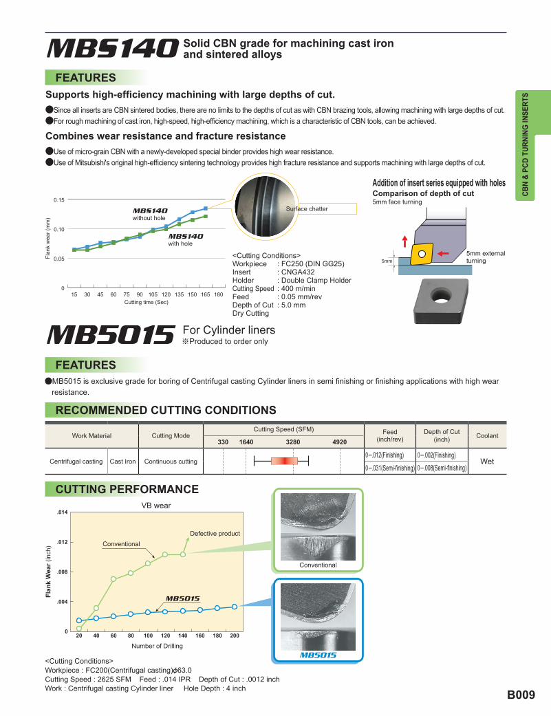
0.15
0.10
0.05
015 30 45 60 75 90 105 120 135 150 165 180
330 1640 3280 4920
MB5015
5mm
MB5015
.014
.012
.008
.004
CBN
& PC
D TU
RNIN
G IN
SERT
S
FEATURES
Flan
k w
ear (
mm
)
Cutting time (Sec)
with hole
without hole
<Cutting Conditions>Workpiece : FC250 (DIN GG25)Insert : CNGA432Holder : Double Clamp HolderCutting Speed : 400 m/minFeed : 0.05 mm/revDepth of Cut : 5.0 mmDry Cutting
Surface chatter
5mm external turning
Comparison of depth of cut5mm face turning
aSince all inserts are CBN sintered bodies, there are no limits to the depths of cut as with CBN brazing tools, allowing machining with large depths of cut.aFor rough machining of cast iron, high-speed, high-efficiency machining, which is a characteristic of CBN tools, can be achieved.
aUse of micro-grain CBN with a newly-developed special binder provides high wear resistance.aUse of Mitsubishi's original high-efficiency sintering technology provides high fracture resistance and supports machining with large depths of cut.
Supports high-efficiency machining with large depths of cut.
Combines wear resistance and fracture resistance
Addition of insert series equipped with holes
Solid CBN grade for machining cast iron and sintered alloys
For Cylinder linersProduced to order only
FEATURES
CUTTING PERFORMANCE
RECOMMENDED CUTTING CONDITIONS
aMB5015 is exclusive grade for boring of Centrifugal casting Cylinder liners in semi finishing or finishing applications with high wear resistance.
Flan
k W
ear (
inch
)
Number of Drilling
Conventional
Conventional
Defective product
VB wear
<Cutting Conditions>Workpiece : FC200(Centrifugal casting)&63.0Cutting Speed : 2625 SFM Feed : .014 IPR Depth of Cut : .0012 inchWork : Centrifugal casting Cylinder liner Hole Depth : 4 inch
Work Material Cutting ModeCutting Speed (SFM) Feed
(inch/rev)Depth of Cut
(inch) Coolant
Wet0─.002(Finishing)0─.008(Semi-finishing)0─.031(Semi-finishing)
0─.012(Finishing)Continuous cuttingCast IronCentrifugal casting

B010
MB4020
a�
a�
a�
y
40 60 80 100
985
655
330
MB4020
MB835
NEW
NEW
SF
SE
FS
TS
NEW
NEW
SF SE(RH.0004")
FS(.004"×15°+RH.0004")
CBN
& PC
D TU
RNIN
G IN
SERT
SCBN & PCD TURNING INSERTS
FEATURES
Cut
ting
Spee
d (S
FM)
Hardness of Work Material (HRB)
SINTERED ALLOY MACHINING
Newly developed special binder provides high cutting edge strength. Burrs and plasticity characteristics must be suppressed in interrupted cutting of sintered alloy machining. Extremely superior work accuracy is realized because MB4020 allows selection of a sharper cutting shape to perform its high cutting edge strength.
There is almost no welding to the cutting edge because the stable CBN contents is high. Work cutting dimensional accuracy is stable.
High cutting edge strength
Excellent welding resistance
Strength of Cutting Edge
Sha
rpne
ss o
f Cut
ting
Edg
e
Expansion SF and SE to edge treatment system of MB4020.SF and SE suppresses burr of work piece and achieves good surface roughness, because SF and SE are sharper than conventional edge preparation and low cutting resistance.Recommend SE, when chipping cutting edge occur using SF.
New Edge Treatment
Application example
Insert : MB4020 NP-TNGA331Workpiece : General Sintered AlloyCutting Mode : Interrupted face cuttingCutting Speed : 985 SFMFeed : .0024 IRPDepth of Cut : .008 inchWet Cutting
<Cutting Conditions>
*Recommend SE, when chipping cutting edge occur using SF.
FS honing SF honing, SE honing
Burr and Edge Chipping Excellent Cutting Accuracy
Chamfer Width
Honing Sharp edge Honing
Rake face Rake face Rake face
Angle
Flan
k fa
ce
Flan
k fa
ce
Flan
k fa
ce
Sharp edge
Honing
Chamfer
Chamfer
High
Hig
h
Low
Low

B011
y y
NP-TNGA331-FS3 NP-CNGA431-SE2 CCGW060204FS
820 820 1220→1370
.004 .005 .0012→.0146
.008 .008 .0051
0 200 400 0 150 300 450 600
MB4020 MB4020 MB4020
0 200 400
100 300 500 700 17 34 51 68 85 102
80
60
40
20
0
80
60
40
20
0
MB4020
MB4020
CBN
& PC
D TU
RNIN
G IN
SERT
S
Surf
ace
Rou
ghne
ss
Ra
(!/in
ch)
Number of Workpiece (pcs./corner)
Conventional B
Conventional A
Fracture
Continuous Cutting of High Density Sintered Alloy
Surf
ace
Rou
ghne
ss
Ra
(!/in
ch)
Number of Workpiece (pcs./corner)
Conventional B
Conventional A
Fracture
Fracture
<Cutting Conditions>Workpiece : High Strength Sintered Alloy Insert : NP-CNGA432-FS2Cutting Speed : 620 SFM Feed : .006 IPR Depth of Cut : .004 inchWet Cutting
<Cutting Conditions>Workpiece : Sintered Alloy Insert : NP-CNGA432-FS2Cutting Speed : 330 SFM Feed : .006 IPR Depth of Cut : .004 inchWet Cutting
Continuous Cutting of Sintered Alloy
Full face CBN insert can be used for chamfering that use higher depth of cut
Full face CBN
Range of useRange of
use
Full face CBN
CUTTING PERFORMANCE
APPLICATION EXAMPLEInsert
Workpiece
Carburized and quenched alloy Carburized and quenched alloy Gray Cast Iron No 35 B
Component Variable valve parts Variable valve parts Crankcase
Cut
ting
Con
ditio
ns
Cutting Speed (SFM)
Feed (IPR)
Depth of Cut (inch)
Coolant Wet cutting Wet cutting Wet cutting
Results
(pieces/ corner)
(pieces/ corner)
(pieces/ corner)
Conventional Conventional Conventional

B012
150 250 300 350
a
a
a
MB4020 820 (260─985) 0─ .008 0─ .012
MB4020 490 (260─820) 0─ .008 0─ .012
MB4020, MB835 330 (260─490) 0─ .008 0─ .012
820 1640 2460 3280 4100
─ 0─ .0200─ .039MBS1400─ .197
0─ .016 0─ .020
60-40-180─ .016 0─ .020
100-70-03 MB730
MB710
MB710MB730
MBS140
MB4020
35─65HRC
BC8105 820 (330─1150) 0─ .006 0─ .008
MBC010 820 (490─1310) 0─ .008 0─ .008
BC8110 655 (330─985) 0─ .008 0─ .012
MBC020 655 (260─820) 0─ .008 0─ .012
BC8120 655 (260─820) 0─ .012 0─ .030
BC8020 490 (195─655) 0─ .008 0─ .012
BC8130 390 (195─490) 0─ .008 0─ .012
MB8025590 (260─820) 0─ .012 0─ .020
390 (195─490) 0─ .008 0─ .012
MB835 330 (165─390) 0─ .012 0─ .020
NEW
NEW
NEW
MB4020
MB4020 MB710
MB825 MB835
MB825
CBN
& PC
D TU
RNIN
G IN
SERT
SCBN & PCD TURNING INSERTS
Suitable for high speed finishing of heat treated steel, sintered ferrous alloy and cast iron.Low affinity to iron, thus good surface finishes are possible. Present grinding processes can now be machined reducing cost and time.
a Heat Treated Steel
a Cast Iron
a Sintered Alloy
a Valve SeatNone or Small Large
SELECTION STANDARD
CBN
Amount of Hard ParticlesHardness of Workpiece (HV)
Plunge Cut
Traverse Cut
Work Material
Gray Cast Iron
Alloy Cast Iron
Ductile Cast Iron
Work Material
General Sintered Alloy
High Density Sintered Alloy
Sintered Alloy
Workpiece Structure
Pearlitic
Ferritic
Ferritic + PearliticPearlitic
Recommended Grade
Cutting Speed (SFM)
Recommended Cutting ConditionCutting Speed (SFM) Feed (IPR)
Feed(IPR)
Depth of Cut(inch) Coolant
Dry,Wet
Dry,Wet
Dry,Wet
Depth of Cut (inch)
Work MaterialRecommended Cutting Condition
Feed (IPR)
Structural Steel
High Alloy Steel
Non
-coa
ted
Coa
ted
Type Cutting Mode
High speed finish cutting
Continuous cutting for general purpose
Heavy interrupted cutting for general purpose
Interrupted cutting for general purpose
Interrupted cutting
Continuous cutting
Light interrupted cutting
Interrupted cutting
Recommended Grade Cutting Speed (SFM) Depth of Cut (inch)

B013
MB730, MB8025 390 (330─490) 0─ .008 0─ .020
MB730, MB8025 230 (165─330) 0─ .008 0─ .020
MB825, MB8025 260 (100─425) .012 (.004─ .020) .008─ .118
MB710 260 (100─425) .012 (.004─ .020) .008─ .118
MB825, MB8025 260 (100─425) .012 (.004─ .020) .008─ .118
MB730 165 (65─230) .010 (.004─ .020) .004─ .118
MB730, MBS140 65 (30─100) 0─ .020 0─ .008
CBN
& PC
D TU
RNIN
G IN
SERT
S
a Roll
a Heat Resistant Alloy
Work Material
Ni Base Heat Resistant Alloy (e.g. Inconel)
Co Base Heat Resistant Alloy (e.g. Stellite)
GradeCutting Speed (SFM)
Recommended Cutting ConditionFeed (IPR) Depth of Cut (inch)
Work Material
Cast SteelAdamite Cast Steel
Ductile Cast IronGranular Cast IronChilled Cast Iron
High Chromium SteelHigh Alloy Steel
High Speed Steel
Cemented Carbide
GradeCutting Speed (SFM)
Recommended Cutting ConditionFeed (IPR) Depth of Cut (inch)

B014
NP-CNMA431- G 2
F
FA FS FN
TA TS TN
GA GS GN
F
T
G
A S N
G
T
NP-CNGA431- G S 2
FN
FA
GS
FS
TS
TN
GN
GA
TA
T
F
G
"
"
CBN
& PC
D TU
RNIN
G IN
SERT
SCBN & PCD TURNING INSERTS
For the CBN BC8020, MBC010 and MBC020 coated grades, MB4020 and MB710/MB730 a wide range of edge honing styles are available to cover a large range of applications and to represent Mitsubishi Materials’ unique cutting tool technology.
Stable cutting
Unstable cutting
1st Recommendation (General cutting)
Honing Honing
Honing
Honing
Honing
Honing
Honing
HoningHoning
HONINGNEW HONING TYPES
aGeneral cutting
aContinuous cutting, stable cutting
aMedium and heavy interrupted cutting, unstable cutting
GA honing is the first recommendation.GS honing if the depth of cut is .004 inch or more. GN honing if crater wear is too large.
FA honing to improve the initial machining performance.FS honing is the first recommendation.FN honing if crater wear is too large.
TA honing is the first recommendation.TS honing if the depth of cut is .004 inch or more.TN honing if crater wear is too large.
CONVENTIONAL HONING TYPESOther than the new honing types, the three conventional honing types, F, G and T types are available for use in accordance to the machining application.
(Note) First, select the insert edge type from the main application area (F,G,T) then choose honing (A,S,N) that compliments the machining requirement.
1st Recommendation (General cutting)
Stable cutting
Unstable cutting
Honing
Honing
Honing
Honing Honing Honing
Honing Honing Honing
Honing Honing Honing
MAIN APPLICATION
EDGE HONING TYPE
For Continuous Machining
For Interrupted Machining
For Continuous ─Light Interrupted Machining
For GeneralPurpose Machining
For SmallDepth of Cut
(1st recommendation) (Crater wear resistant)(Sharp anti-burr type)
Main Application Edge Honing Type
For Anti Chatter
HONINGFor stable continuous cutting.
For general purpose cutting.(Including light to medium interrupted cutting).
For medium to heavy interrupted cutting.
HONING
HONING
Honing Type
"
"

B015
H 35─65HRC MB8025 330(195─390)
420
.004
( GY )
a
a
a
y
BC8110
MB8025
0 .002 .004 .006 .008
.079
.157
.094
.098
.125
.187
.197
.118
CBN
& PC
D TU
RNIN
G IN
SERT
S
Holder rigidity is essential when grooving hardened steel. The GY series Tri Lock system offers high rigidity equivalent to a 1-piece type tool holder despite being a modular system.
A CBN coated grade for continuous cutting, which provides longer life when machining hardened steel.
MB8025 is a sintered CBN grade for hardened steel.
Combined with a High-rigidity Holder Ensures High Accuracy and Long Tool Life.
Tool life
Flan
k W
ear (
inch
)
Inse
rt W
idth
(inc
h)
Competitor A
Number of Passes
<Cutting Conditions>Workpiece : Hardened Steel (HRC60)Cutting Speed : 390 SFMFeed : .004 IPR
Depth of Cut : .014 inchDry Cutting
Feed (inch/rev)
Competitor’s CBN grade Fracture
(pieces)
GY achieves longer tool life without fracturing.
Transmission shaft (AISI 8620 (HRC58─62))
Competitor B
FEATURES
CBN GRADE
RECOMMENDED CUTTING CONDITIONS
APPLICATION EXAMPLE
CUTTING PERFORMANCE
CBN GROOVING SERIES
Work Material
Hardened Steel
Hardness Grade Cutting Speed(SFM) Coolant
Dry,Wet
Insert
Workpiece
Cutting Speed (SFM)
Feed (IPR)Cutti
ng
Cond
itions
Result
GY1G0300F020N-GFGS (Grade : MB8025)

B016
NP-CNGA432-GA4
NP-CNGA432-GA2
a
a
a
y
y
y
CBN
& PC
D TU
RNIN
G IN
SERT
SCBN & PCD TURNING INSERTS
Radial chip breaker ensures optimization of the cutting point and the chip breaker position. Enables effective chip discharge even when copy machining and prevents the chips from wrapping around the holder under finish cutting conditions.
Combination of Coating grade & Breaker, high efficiency and long tool life in wide variety of applications.
A single sided, multi-corner type insert has no cutting edges on the 2nd side. The type of grade is stamped on the 1st side.
No. of Cutting Edges
No. of Cutting Edges
1st side 2nd side
Chip breaker geometry designed for excellent chip control
Long life coated CBN grade
BM Breaker
BF Breaker
Double sided, multi-corner type insert
Dep
th o
f Cut
( inc
h)
Feed (IPR)
FEATURES
DEEP CUTTING DEPTH
APPLICATION AREA
Double Sided, multi-corner type insert, ex.
Single Sided, multi-corner type insert, ex.
CBN BREAKER INSERT
MULTI-CORNER TYPE INSERTS
Good for deep depth cutting of carburized layer.
Recommend and under ap=.024 inch
Conventional (Light cutting depth)
Conventional
BF breaker
Good for chip removal under light depth and feed cutting.
Recommend and under ap=.012 inch
Available in BC8020 grade.
Available in MBC020 grade.
Cutting Performance
Cutting Performance
<Cutting Conditions>
<Cutting Conditions>
Workpiece : Hardened Steel(60HRC)Insert : BM-CNGM432-TA2Cutting Speed : 590 SFMFeed : .008 IPRDepth of Cut : .020 inchDry Cutting
Workpiece : Hardened Steel(55HRC)Insert : BF-CNGG432-TA4Cutting Speed : 330 SFMFeed : .008 IPRDepth of Cut : .004 inchDry Cutting
Cutting Time (min)
Flan
k W
ear (
inch
)
FractureFracture
BF breaker Area
BM breaker Area
(BM/BF BREAKER)
LIGHT CUTTING DEPTH

B017
a
a
a
y
y y
y
y y
600
400
200
0.002 .004 .008 .012
NP-DNGA431-GAWS2JL
CBN
& PC
D TU
RNIN
G IN
SERT
S
• The wiper insert is designed with a wiper edge that is situated where the straight edge meets the corner radius. Under the same machining conditions as conventional inserts, but with the
feed rate increased, the surface finish of the workpiece can be improved.
High feed rates not only shorten machining times but also make it possible to combine roughing and finishing operations.
When changing to high feed conditions, the time required to cut one component is decreased, thus more parts can be machined with each insert. In addition, the high feed rate prevents rubbing, therefore, delaying the progression of wear and increasing the tool life of the insert.
• Reduced machining time • Increased production rate • Improved chip control
• Reducing cost • Increased productivity • Reduced machine down time
Use a holder with an end cutting angle of 93° to improve wiper efficiency. A holder with a cutting edge angle of 91° can marginally improve wiper efficiency (see the figure below), however, there is no wiper efficiency with other end cutting angles (60°, 90°, 107°etc.).
• Eliminating the finishing step (Combine roughing and finishing into single pass.)
• In comparison to conventional inserts, the surface finish does not deteriorate even if the feed rate is doubled.
<Cutting Conditions> Workpiece : Hardened steel (HRC60)Insert : NP-CNGA432-ooo
Cutting Speed : 390 SFMDepth of Cut : .004 inchDry Cutting
The standard holder can be used as it is.(* The double clamp, high rigidity holder
is recommended.)End Cutting
Angle95°Non
restriction 93°
(Specified)
Feed rate (IPR)
Feed (IPR)
Sur
face
fini
sh (!
inch
)
• Machining at high feed rates improves machining efficiency.
What is a Wiper Insert?
Cutting Performance
No Restriction for Holder Restriction for Holders
Improving Surface Finish
Improving Efficiency
Increased Tool Life
Wiper insert + machining at high feed rates
Wiper insert + machining at conventional feed rates
<Real cost reduction!!>
Special attention is not necessary when using C-style and W-style inserts
Cutting Conditions and Performance
High precision finishing High feed, highly efficient cuttingHigh feed, high efficient cutting
Cutting speed : 330 SFM Feed : .004 IPRDepth of cut : .004 inch Dry cutting
Cutting speed : 330 SFM Feed : .012 IPRDepth of cut : .004 inch Dry cutting
Without WiperWithout Wiper
Ry=126!inch Ry=40!inch Ry=480!inch Ry=47!inch
With WiperWith Wiper
High precision finishing
WIPER INSERT
End Cutting Angle
Dep
th o
f cut
(inc
h)
Theoretical finished surface roughness
without wiper
with WS wiper
Wiper
Left hand wiper shown
Wiper DesignationMultiple Tip
Direction

B018
y
MD205 MD220 MD230
e 3280 (650─4920) 0 ─.008 0 ─.200e 2630 (650─3940) 0 ─.008 0 ─.200u 1970 (650─3280) 0 ─.008 0 ─.118e 2300 (650─3940) 0 ─.008 0 ─.118e 1970 (330─3280) 0 ─.016 0 ─.079e 1640 (330─2630) 0 ─.010 0 ─.079
u e 1210 (330─1970) 0 ─.012 0 ─.079u 165 (100─260) 0 ─.004 0 ─.079e 1970 (980─2630) 0 ─.006 0 ─.039e 4260 (980─12100) 0 ─.016 ─u 15 (16─65) 0 ─.008 0 ─.020
a
MD205 MD220 MD230
MD205
MD220
MD230
PCD a
a
a
a
a
CBN
& PC
D TU
RNIN
G IN
SERT
SCBN & PCD TURNING INSERTS
CUTTING PERFORMANCE
Flan
k W
ear (
inch
)
Machined Length (miles)Sintered diamond tool wear for high Si aluminum alloy cutting
<Cutting Conditions>Workpiece : High Si Aluminum AlloyInsert : SPG422vc=655 SFMap=.059 inchf=.006 IPR Coolant : W.S.O
(SINTERED DIAMOND)
FEATURES
TURNING
Economical inserts The small PCD delivers long tool life. Eliminates the need for regrinding, making tool management easier and economical.
PCD with chip breaker Chip breaker formed directly on the PCD portion delivers superior chip control.Corner R.002 inch inserts are available, making it suitable for the machining of small work corner radii.
Suitable for materials such as aluminum alloy, non-ferrous metals, and fiber reinforced plastics.Suitable for extremely high speed finishing.
(Note 1) e : 1st recommendation. u : 2nd recommendation.(Note 2) Not suitable for steel.
SELECTION STANDARD
NEW PETIT CUT PCD INSERTS
Work MaterialRecommended Grade Recommended Cutting Condition
Recommended Cutting Speed (SFM) Feed (IPR) Depth of Cut (inch)
AluminumAluminum Alloy (Si < 16%)
Aluminum Alloy (Si < 16%)
Copper AlloyReinforced Plastic
Glass Fiber Reinforced PlasticCarbon
CeramicsHard Rubber
Wood Inorganic BoardTungsten Carbide
Grade
Please use when there is insufficient resistance to wear with the MD220.
Apply for general finishing of non-ferrous metals and non-metal cutting.
Please use when a fracture has occured with the MD220 and you desire a high-quality finished surface.
APPLICATION
FEATURES
Fracture Resistance
Wea
r Res
ista
nce
Grade Features
Materials focused on wear resistanceCoarse grain diamond particles are sintered and wear resistance is excellent. Use when wear resistance with MD220 is insufficient.
Materials for general machiningSintered medium grain diamond particles. Wear resistance and fracture resistance are superbly balanced. Applicable to general finishing of non-ferrous metals, non-metal cutting, and similar machining.
Materials focused on fracture resistanceFine grain diamond particles are used. Fracture resistance and cutting edge sharpness are excellent. Use when fracture and a high quality finished surface is demanded with MD220.

B019
Memo

B020
NP-CNGA_o4
^ B026
NP-DNGA_o4
^ B029
NP-SNGA_o4
^ B033
NP-TNGA_o6
^ B034
NP-VNGA_o4
^ B036
NP-WNGA_o6
^ B038NP-CNGA_oWS4
^ B026
BF BF-CNGG_o4
^ B026
BF-DNGG_o4
^ B030NP-CNGA_o2
^ B027
NP-DNGA_o2
^ B030, B031
NP-SNGA_o2
^ B033
NP-TNGA_o3
^ B034, B035
NP-VNGA_o2
^ B036
NP-WNGA_o3
^ B038NP-CNGA_oWS2
^ B027
NP-DNGA_oWS2JR/L
^ B031
NP-TNGA_oWS3JR/L
^ B029
NP-WNGA_oWS3
^ B038
BF BF-DNGA_o2
^ B025
BF BF-CNGM_o2
^ B028
BF-DNGM_o2
^ B032
BM BM-CNGM_o2
^ B028
BM-DNGM_o2
^ B032
BM-TNGM_o3
^ B035
CBN
& PC
D TU
RNIN
G IN
SERT
SCBN & PCD TURNING INSERTS
CLASSIFICATIONNEGATIVE INSERTS WITH HOLE
Produ
ct Nam
e
TypeTo
lera
nce
Breaker and
Cross Section
Rhombic 80° Rhombic 55° Square 90° Triangular 60° Rhombic 35° Trigon 80°
Multi-corner TypeDouble Sided
Multi-corner TypeDouble Sided
With Wiper
Multi-corner TypeDouble SidedWith Breaker
Multi-corner TypeSingle Sided
Multi-corner TypeSingle SidedWith Wiper
Multi-corner TypeSingle SidedWith Breaker
Multi-corner TypeSingle SidedWith Breaker
Multi-corner TypeSingle SidedWith Breaker
G C
lass
NEW
PET
IT C
UT
Flat Top
Flat Top
Flat Top
Flat Top

B021
NP-VNMA_o
^ B037
R/L F NP-CNMM_RF
^ B059
NP-DNMM_RF
^ B059
NP-SNMM_RF
^ B060
NP-TNMM_RF
^ B060
NP-VNMM_RF
^ B061CNGA
^ B028
SNGA
^ B033
TNGA
^ B036CNGA
^ B028
DNGA
^ B059
SNGA
^ B033, B060
TNGA
^ B035, B060
VNGA
^ B037, B061CNMA
^ B028, B059
NP-VBGW_o2
^ B051
RFNP-VBGT_RF
^ B068
CBN
& PC
D TU
RNIN
G IN
SERT
SNEGATIVE INSERTS WITH HOLE
5° POSITIVE INSERTS WITH HOLE
Produ
ct Nam
e
TypeTo
lera
nce
Breaker and
Cross Section
Rhombic 80° Rhombic 55° Square 90° Triangular 60° Rhombic 35° Trigon 80°
Produ
ct Nam
e
Type
Tole
ranc
e
Breaker and
Cross Section
Rhombic 80° Rhombic 55° Square 90° Triangular 60° Rhombic 35° Trigon 80°
One-corner TypeSingle Sided
One-corner TypeSingle SidedWith Breaker
Multi-corner TypeDouble Sided
One-corner TypeSingle Sided
One-corner TypeSingle Sided
M C
lass
G C
lass
M C
lass
STA
ND
AR
DN
EW P
ETIT
CU
T
Flat Top
Flat Top
Flat Top
Flat Top
G C
lass
NEW
PET
IT C
UT Multi-corner Type
One-corner TypeWith Breaker
Flat Top

B022
NP-CCGW/B_o2
^ B042
NP-DCGW_o2
^ B046
NP-TCGW_o3
^ B048
NP-VCGW_o2
^ B052
NP-WCGW_o3
^ B053NP-CCGW_oWS2
^ B043
BF BF-CCGT_o2
^ B043
BF-DCGT_o2
^ B047
BF BF-CCGW_o2
^ B043
BF-DCGW_o2
^ B047
BM BM-CCGT_o2
^ B044
BM-DCGT_o2
^ B047NP-CCGW/B_o
^ B044NP-CCMW
^ B063NP-CCMH
^ B063
RF NP-VCGT_RF
^ B068
R/L F NP-DCMT_R/LF
^ B064
CBN
& PC
D TU
RNIN
G IN
SERT
SCBN & PCD TURNING INSERTS
7° POSITIVE INSERTS WITH HOLE
CLASSIFICATIONPro
duct N
ame
TypeTo
lera
nce
Breaker and
Cross Section
Rhombic 80° Rhombic 55° Square 90° Triangular 60° Rhombic 35° Trigon 80°
Multi-corner Type
Multi-corner TypeWith Wiper
Multi-corner TypeWith Breaker
Multi-corner TypeWith Breaker
Multi-corner TypeWith Breaker
One-corner Type
One-corner Type
One-corner TypeWith Breaker
One-corner TypeWith Breaker
One-corner TypeWith Breaker
Flat Top
Flat Top
Flat Top
Flat Top
Breaker
M C
lass
G C
lass
M C
lass
G C
lass
NEW
PET
IT C
UT

B023
CCGW
^ B044
DCGW
^ B047CCGW
^ B044
DCGW
^ B047
TCGW
^ B048, B065CCMW
^ B063
DCMW
^ B064
TCMW
^ B065
WCMW
^ B069
NP-CPGB_o2
^B045
NP-TPGB_o3
^ B049NP-TPGX_o3
^ B050NP-TPGX_oF
^ B050NP-CPMH
^ B063
R/L FNP-TPMH_R/LF
^ B066
R/L FNP-TPMX_R/LF
^ B066
CBN
& PC
D TU
RNIN
G IN
SERT
S
Multi-corner Type
One-corner Type
One-corner Type
Flat Top
7° POSITIVE INSERTS WITH HOLE
11° POSITIVE INSERTS WITH HOLE
Flat Top
Flat Top
Flat Top
Flat Top
Flat Top
Breaker
Produ
ct Nam
e
Type
Tole
ranc
e
Breaker and
Cross Section
Rhombic 80° Rhombic 55° Square 90° Triangular 60° Rhombic 35° Trigon 80°
Produ
ct Nam
e
Type
Tole
ranc
e
Breaker and
Cross Section
Rhombic 80° Rhombic 55° Square 90° Triangular 60° Rhombic 35° Trigon 80°
Multi-corner Type
Multi-corner Type
One-corner Type
One-corner TypeWith Breaker
One-corner TypeWith Breaker
One-corner TypeWith Breaker
STA
ND
AR
D
M C
lass
G C
lass
G C
lass
M C
lass
NEW
PET
IT C
UT

B024
R/L VDGX_R/LF
^ B071
R/L TEGX_R/L
^ B070
R/L F DEGX_R/LF
^ B070TEGX
^ B070
CPGT
^ B063
WPGT
^ B069SPGX
^ B064
TPGX
^ B050, B067
R/L F TPGT/V_R/LF
^ B066, B067
CBN
& PC
D TU
RNIN
G IN
SERT
SCBN & PCD TURNING INSERTS
20° POSITIVE INSERTS WITH HOLE15° POSITIVE INSERTS WITH HOLE
CLASSIFICATIONPro
duct N
ame
Type
Tole
ranc
e
Breaker and
Cross Section Produ
ct Nam
e
Type
Tole
ranc
e
Breaker and
Cross Section
Flat Top
Rhombic 35° Rhombic 55° Triangular 60°
G C
lass
G C
lass
FOR
ALU
MIN
UM
FOR
ALU
MIN
UM
One-corner TypeWith Breaker
One-corner TypeWith Breaker
One-corner TypeWith Breaker
One-corner Type
11° POSITIVE INSERTS WITH HOLE
Flat Top
Breaker
Produ
ct Nam
e
TypeTo
lera
nce
Breaker and
Cross Section
Rhombic 80° Rhombic 55° Square 90° Triangular 60° Rhombic 35° Trigon 80°
One-corner TypeWith Breaker
One-corner Type
One-corner TypeWith Breaker
G C
lass
STA
ND
AR
D

B025
SNG
^ B040, B062
TNG
^ B041CNG
^ B039
DNG
^ B039
SNG
^ B040
TNG
^ B041
RNG
^ B040
TBG
^ B056
SPG
^ B055, B072
TPG
^ B058, B072
RTG_A
^ B054
CBN
& PC
D TU
RNIN
G IN
SERT
SNEGATIVE INSERTS WITHOUT HOLE
5° POSITIVE INSERTS WITHOUT HOLE
11° POSITIVE INSERTS WITHOUT HOLE SPECIAL PURPOSE INSERTS
Flat Top
Flat Top
Flat Top
G C
lass
G C
lass
G C
lass
G C
lass
Product Name
Tole
ranc
eBreaker
and Cross Section
Product Name
Tole
ranc
e
Breaker and
Cross Section
Product Name
Tole
ranc
e
Breaker and
Cross Section
Rhombic 80° Rhombic 55° Square 90° Triangular 60° Round
STANDARD
STANDARD
STANDARD TL Type
Square 90° Triangular 60°Tool Holder
Type
Tole
ranc
e
Inserts
Triangular 60°
Flat TopSTANDARD

B026
NEG
CBN
NP-CNGA 4 3 1 GA480° CNHKS
CBN
MB
C01
0M
BC
020
BC
8020
BC
8105
BC
8110
BC
8120
BC
8130
MB
810
MB
8025
MB
825
MB
835
MB
710
MB
730
MB
4020
MB
S140
NP-CNGA431-GA4 NP-CNGA120404GA4 .016 a a s s
C006─009E021E024H006─008
NP-CNGA432-GA4 NP-CNGA120408GA4 .031 a a s s
NP-CNGA433-GA4 NP-CNGA120412GA4 .047 a s s s
NP-CNGA431-GS4 NP-CNGA120404GS4 .016 a s
NP-CNGA432-GS4 NP-CNGA120408GS4 .031 a s
NP-CNGA433-GS4 NP-CNGA120412GS4 .047 a s
NP-CNGA431-GN4 NP-CNGA120404GN4 .016 s
NP-CNGA432-GN4 NP-CNGA120408GN4 .031 s
NP-CNGA433-GN4 NP-CNGA120412GN4 .047 s
NP-CNGA431-GH4 NP-CNGA120404GH4 .016 a a a
NP-CNGA432-GH4 NP-CNGA120408GH4 .031 a a a
NP-CNGA433-GH4 NP-CNGA120412GH4 .047 a a a
NP-CNGA431-FS4 NP-CNGA120404FS4 .016 s a s s
NP-CNGA432-FS4 NP-CNGA120408FS4 .031 s a s s
NP-CNGA433-FS4 NP-CNGA120412FS4 .047 s a s s
NP-CNGA431-TA4 NP-CNGA120404TA4 .016 s s s s
NP-CNGA432-TA4 NP-CNGA120408TA4 .031 s s s s
NP-CNGA433-TA4 NP-CNGA120412TA4 .047 s s s s
NP-CNGA431-TS4 NP-CNGA120404TS4 .016 s
NP-CNGA432-TS4 NP-CNGA120408TS4 .031 s
NP-CNGA433-TS4 NP-CNGA120412TS4 .047 s
NP-CNGA431-TH4 NP-CNGA120404TH4 .016 a s
NP-CNGA432-TH4 NP-CNGA120408TH4 .031 a s
NP-CNGA433-TH4 NP-CNGA120412TH4 .047 a s
NP-CNGA431-FSWS4 NP-CNGA120404FSWS4 .016 a a a
C006─009E021E024H006─008
NP-CNGA432-FSWS4 NP-CNGA120408FSWS4 .031 a a a
NP-CNGA433-FSWS4 NP-CNGA120412FSWS4 .047 a a a
NP-CNGA431-GAWS4 NP-CNGA120404GAWS4 .016 s s s
NP-CNGA432-GAWS4 NP-CNGA120408GAWS4 .031 a s s
NP-CNGA433-GAWS4 NP-CNGA120412GAWS4 .047 a s s
NP-CNGA431-GSWS4 NP-CNGA120404GSWS4 .016 a s
NP-CNGA432-GSWS4 NP-CNGA120408GSWS4 .031 a s
NP-CNGA433-GSWS4 NP-CNGA120412GSWS4 .047 a s
BF-CNGG431-TA4 BF-CNGG120404TA4 .016 s C006─009E021E024H006─008
BF-CNGG432-TA4 BF-CNGG120408TA4 .031 s
BF-CNGG433-TA4 BF-CNGG120412TA4 .047 s
*1
*1
*1
*1
*1
*1
*1
*1
*1
=
CBN
& PC
D TU
RNIN
G IN
SERT
S
TYPE INSERTSWITH HOLE Size Thickness Corner Radius Honing & Wiper
*Please refer to page B002.
Cutting Conditions : Stable Cutting General Cutting Unstable Cutting
Work Material
Shape Order Number (ISO) Number
Corner Radius
RE
(inch)
NEW PETIT CUT
NEW PETIT CUT(With Wiper)
NEW PETIT CUT
(With breaker)
Coated CBN
*1 Please refer to page B017 before using the wiper insert.
Hardened MaterialsCast IronHeat-resistant Alloy, Titanium AlloySintered Alloy
Solid CBN
WITH HOLE
CBN TURNING INSERTS [NEGATIVE]
a : Inventory maintained. s : Inventory maintained in Japan. <1 insert in one case>
App
licab
le
Hol
der P
age

B027
CBN
NEG
B002B014
HKS
CBN
MB
C01
0M
BC
020
BC
8020
BC
8105
BC
8110
BC
8120
BC
8130
MB
810
MB
8025
MB
825
MB
835
MB
710
MB
730
MB
4020
MB
S140
NP-CNGA430.5-GA2 NP-CNGA120402GA2 .008 a
C006─009E021E024H006─008
NP-CNGA431-GA2 NP-CNGA120404GA2 .016 a a a a a
NP-CNGA432-GA2 NP-CNGA120408GA2 .031 a a a a a
NP-CNGA433-GA2 NP-CNGA120412GA2 .047 a a a a a
NP-CNGA430.5-GS2 NP-CNGA120402GS2 .008 a
NP-CNGA431-GS2 NP-CNGA120404GS2 .016 a a a a a a a
NP-CNGA432-GS2 NP-CNGA120408GS2 .031 a a a a a a a
NP-CNGA433-GS2 NP-CNGA120412GS2 .047 a a a a a a a
NP-CNGA431-SE2 NP-CNGA120404SE2 .016 a
NP-CNGA432-SE2 NP-CNGA120408SE2 .031 a
NP-CNGA433-SE2 NP-CNGA120412SE2 .047 a
NP-CNGA431-SF2 NP-CNGA120404SF2 .016 a
NP-CNGA432-SF2 NP-CNGA120408SF2 .031 a
NP-CNGA433-SF2 NP-CNGA120412SF2 .047 a
NP-CNGA431-GN2 NP-CNGA120404GN2 .016 a
NP-CNGA432-GN2 NP-CNGA120408GN2 .031 a
NP-CNGA433-GN2 NP-CNGA120412GN2 .047 a
NP-CNGA431-GH2 NP-CNGA120404GH2 .016 a a a
NP-CNGA432-GH2 NP-CNGA120408GH2 .031 a a a
NP-CNGA433-GH2 NP-CNGA120412GH2 .047 a a a
NP-CNGA430.5-FS2 NP-CNGA120402FS2 .008 a
NP-CNGA431-FS2 NP-CNGA120404FS2 .016 s a a a a a a
NP-CNGA432-FS2 NP-CNGA120408FS2 .031 a s a a a a a a
NP-CNGA433-FS2 NP-CNGA120412FS2 .047 s a a a a a a
NP-CNGA431-TA2 NP-CNGA120404TA2 .016 a s a a a a a
NP-CNGA432-TA2 NP-CNGA120408TA2 .031 a s a a a a a
NP-CNGA433-TA2 NP-CNGA120412TA2 .047 a s a a a a a
NP-CNGA431-TS2 NP-CNGA120404TS2 .016 s a
NP-CNGA432-TS2 NP-CNGA120408TS2 .031 s a
NP-CNGA433-TS2 NP-CNGA120412TS2 .047 s a
NP-CNGA431-TH2 NP-CNGA120404TH2 .016 a a
NP-CNGA432-TH2 NP-CNGA120408TH2 .031 a a
NP-CNGA433-TH2 NP-CNGA120412TH2 .047 a a
NP-CNGA432-G2 NP-CNGA120408G2 .031 s
NP-CNGA431-GAWS2 NP-CNGA120404GAWS2 .016 a a a
C006─009E021E024H006─008
NP-CNGA432-GAWS2 NP-CNGA120408GAWS2 .031 a a a a
NP-CNGA433-GAWS2 NP-CNGA120412GAWS2 .047 a a a a
NP-CNGA431-GSWS2 NP-CNGA120404GSWS2 .016 s a a
NP-CNGA432-GSWS2 NP-CNGA120408GSWS2 .031 a a a
NP-CNGA433-GSWS2 NP-CNGA120412GSWS2 .047 s a a
NP-CNGA431-FSWS2 NP-CNGA120404FSWS2 .016 a a a
NP-CNGA432-FSWS2 NP-CNGA120408FSWS2 .031 a a a
NP-CNGA433-FSWS2 NP-CNGA120412FSWS2 .047 a a a
*1
*2
*2
*2
*2
*2
*2
*2
*2
=
CBN
& PC
D TU
RNIN
G IN
SERT
S
Work Material
Shape Order Number (ISO) Number
Corner Radius
RE
(inch)
NEW PETIT CUT
Coated CBN
Cutting Conditions : Stable Cutting General Cutting Unstable Cutting
NEW PETIT CUT(With Wiper)
*1 This order number is for "10 inserts in one case" package.
*2 Please refer to page B017 before using the wiper insert.
Hardened MaterialsCast IronHeat-resistant Alloy, Titanium AlloySintered Alloy
Solid CBN
WITH HOLE
IDENTIFICATIONHONING
App
licab
le
Hol
der P
age

B028
NEG
CBN80° CN BF-CNGM 4 3 1 TA2
=
HKS
CBN
MB
C01
0M
BC
020
BC
8020
BC
8105
BC
8110
BC
8120
BC
8130
MB
810
MB
8025
MB
825
MB
835
MB
710
MB
730
MB
4020
MB
S140
BF-CNGM431-TA2 BF-CNGM120404TA2 .016 a a
C006─009E021E024H006─008
BF-CNGM432-TA2 BF-CNGM120408TA2 .031 a a
BF-CNGM433-TA2 BF-CNGM120412TA2 .047 a a
BF-CNGM431-TS2 BF-CNGM120404TS2 .016 s
BF-CNGM432-TS2 BF-CNGM120408TS2 .031 s
BF-CNGM433-TS2 BF-CNGM120412TS2 .047 s
BM-CNGM431-TA2 BM-CNGM120404TA2 .016 a C006─009E021E024H006─008
BM-CNGM432-TA2 BM-CNGM120408TA2 .031 s a
BM-CNGM433-TA2 BM-CNGM120412TA2 .047 s a
CNGA432 CNGA120408 .031 a a a C006─009E021E024H006─008
CNGA433 CNGA120412 .047 a a a
CNGA432 CNGA120408 .031 a C006─009E021E024H006─008
CNGA433 CNGA120412 .047 a
CNMA431 CNMA120404 .016 s C006─009E021E024H006─008
CBN
& PC
D TU
RNIN
G IN
SERT
S
a : Inventory maintained. s : Inventory maintained in Japan. <1 insert in one case>
TYPE INSERTSWITH HOLE
Cutting Conditions : Stable Cutting General Cutting Unstable Cutting
Work Material
Shape Order Number (ISO) Number
Corner Radius
RE
(inch)
Coated CBN
Hardened MaterialsCast IronHeat-resistant Alloy, Titanium AlloySintered Alloy
Solid CBN
WITH HOLE
CBN TURNING INSERTS [NEGATIVE]
NEW PETIT CUT
(With breaker)NEW PETIT CUT
(With breaker)
Size Thickness Corner Radius Honing & Wiper
*Please refer to page B002.
App
licab
le
Hol
der P
age

B029
CBN
NEG
55° DN NP-DNGA 4 3 1 GA4
B002B014
HKS
CBN
MB
C01
0M
BC
020
BC
8020
BC
8105
BC
8110
BC
8120
BC
8130
MB
810
MB
8025
MB
825
MB
835
MB
710
MB
730
MB
4020
MB
S140
NP-DNGA431-GA4 NP-DNGA150404GA4 .016 a s s s
C010─012E021E024H009─011
NP-DNGA432-GA4 NP-DNGA150408GA4 .031 a s s s
NP-DNGA433-GA4 NP-DNGA150412GA4 .047 a s s s
NP-DNGA441-GA4 NP-DNGA150604GA4 .016 s s
NP-DNGA442-GA4 NP-DNGA150608GA4 .031 s s
NP-DNGA443-GA4 NP-DNGA150612GA4 .047 s s
NP-DNGA431-GH4 NP-DNGA150404GH4 .016 a a a
NP-DNGA432-GH4 NP-DNGA150408GH4 .031 a a a
NP-DNGA433-GH4 NP-DNGA150412GH4 .047 a a a
NP-DNGA441-GH4 NP-DNGA150604GH4 .016 s s s
NP-DNGA442-GH4 NP-DNGA150608GH4 .031 s s s
NP-DNGA443-GH4 NP-DNGA150612GH4 .047 s s s
NP-DNGA431-GS4 NP-DNGA150404GS4 .016 a s
NP-DNGA432-GS4 NP-DNGA150408GS4 .031 a s
NP-DNGA433-GS4 NP-DNGA150412GS4 .047 a s
NP-DNGA441-GS4 NP-DNGA150604GS4 .016 s s
NP-DNGA442-GS4 NP-DNGA150608GS4 .031 s s
NP-DNGA443-GS4 NP-DNGA150612GS4 .047 s s
NP-DNGA431-GN4 NP-DNGA150404GN4 .016 s
NP-DNGA432-GN4 NP-DNGA150408GN4 .031 s
NP-DNGA433-GN4 NP-DNGA150412GN4 .047 s
NP-DNGA431-FS4 NP-DNGA150404FS4 .016 s a s s
NP-DNGA432-FS4 NP-DNGA150408FS4 .031 s a s s
NP-DNGA433-FS4 NP-DNGA150412FS4 .047 s a s s
NP-DNGA441-FS4 NP-DNGA150604FS4 .016 s s
NP-DNGA442-FS4 NP-DNGA150608FS4 .031 s s
NP-DNGA443-FS4 NP-DNGA150612FS4 .047 s s
NP-DNGA431-TA4 NP-DNGA150404TA4 .016 s s s s
NP-DNGA432-TA4 NP-DNGA150408TA4 .031 s s s s
NP-DNGA433-TA4 NP-DNGA150412TA4 .047 s s s s
NP-DNGA441-TA4 NP-DNGA150604TA4 .016 s s
NP-DNGA442-TA4 NP-DNGA150608TA4 .031 s s
NP-DNGA443-TA4 NP-DNGA150612TA4 .047 s s
NP-DNGA431-TH4 NP-DNGA150404TH4 .016 a s
NP-DNGA432-TH4 NP-DNGA150408TH4 .031 a s
NP-DNGA433-TH4 NP-DNGA150412TH4 .047 a s
NP-DNGA441-TH4 NP-DNGA150604TH4 .016 s s
NP-DNGA442-TH4 NP-DNGA150608TH4 .031 s s
NP-DNGA443-TH4 NP-DNGA150612TH4 .047 s s
=
CBN
& PC
D TU
RNIN
G IN
SERT
S
TYPE INSERTSWITH HOLE Size Thickness Corner Radius Honing & Wiper
*Please refer to page B002.
Cutting Conditions : Stable Cutting General Cutting Unstable Cutting
NEW PETIT CUT
Work Material
Shape Order Number (ISO) Number
Corner Radius
RE
(inch)
Coated CBN
Hardened MaterialsCast IronHeat-resistant Alloy, Titanium AlloySintered Alloy
Solid CBN
WITH HOLE
IDENTIFICATIONHONING
App
licab
le
Hol
der P
age

B030
NEG
CBN55° DN NP-DNGA 4 3 1 TS4
HKS
CBN
MB
C01
0M
BC
020
BC
8020
BC
8105
BC
8110
BC
8120
BC
8130
MB
810
MB
8025
MB
825
MB
835
MB
710
MB
730
MB
4020
MB
S140
NP-DNGA431-TS4 NP-DNGA150404TS4 .016 s
C010─012E021E024H009─011
NP-DNGA432-TS4 NP-DNGA150408TS4 .031 s
NP-DNGA433-TS4 NP-DNGA150412TS4 .047 s
NP-DNGA441-TS4 NP-DNGA150604TS4 .016 s
NP-DNGA442-TS4 NP-DNGA150608TS4 .031 s
NP-DNGA443-TS4 NP-DNGA150612TS4 .047 s
BF-DNGG431-TA4 BF-DNGG150404TA4 .016 s C010─012E021E024H009─011
BF-DNGG432-TA4 BF-DNGG150408TA4 .031 s
BF-DNGG433-TA4 BF-DNGG150412TA4 .047 s
NP-DNGA332-GA2 NP-DNGA110408GA2 .031 a a a a
C010─012E021E024H009─011
NP-DNGA430.5-GA2 NP-DNGA150402GA2 .008 a
NP-DNGA431-GA2 NP-DNGA150404GA2 .016 a a a a a
NP-DNGA432-GA2 NP-DNGA150408GA2 .031 a a a a a
NP-DNGA433-GA2 NP-DNGA150412GA2 .047 a a a a a
NP-DNGA440.5-GA2 NP-DNGA150602GA2 .008 s
NP-DNGA441-GA2 NP-DNGA150604GA2 .016 s s
NP-DNGA442-GA2 NP-DNGA150608GA2 .031 s s
NP-DNGA443-GA2 NP-DNGA150612GA2 .047 s s
NP-DNGA431-GH2 NP-DNGA150404GH2 .016 a a a
NP-DNGA432-GH2 NP-DNGA150408GH2 .031 a a a
NP-DNGA433-GH2 NP-DNGA150412GH2 .047 a a a
NP-DNGA441-GH2 NP-DNGA150604GH2 .016 s s s
NP-DNGA442-GH2 NP-DNGA150608GH2 .031 s s s
NP-DNGA443-GH2 NP-DNGA150612GH2 .047 s s s
NP-DNGA332-GS2 NP-DNGA110408GS2 .031 a
NP-DNGA430.5-GS2 NP-DNGA150402GS2 .008 a
NP-DNGA431-GS2 NP-DNGA150404GS2 .016 a a a a a
NP-DNGA432-GS2 NP-DNGA150408GS2 .031 a a a a a
NP-DNGA433-GS2 NP-DNGA150412GS2 .047 a a a a a
NP-DNGA441-GS2 NP-DNGA150604GS2 .016 s s
NP-DNGA442-GS2 NP-DNGA150608GS2 .031 s s
NP-DNGA443-GS2 NP-DNGA150612GS2 .047 s s
NP-DNGA431-SE2 NP-DNGA150404SE2 .016 a
NP-DNGA432-SE2 NP-DNGA150408SE2 .031 a
NP-DNGA433-SE2 NP-DNGA150412SE2 .047 a
NP-DNGA431-SF2 NP-DNGA150404SF2 .016 a
NP-DNGA432-SF2 NP-DNGA150408SF2 .031 a
NP-DNGA433-SF2 NP-DNGA150412SF2 .047 a
=
CBN
& PC
D TU
RNIN
G IN
SERT
S
Cutting Conditions : Stable Cutting General Cutting Unstable Cutting
TYPE INSERTSWITH HOLE Size Thickness Corner Radius Honing & Wiper
*Please refer to page B002.
Work Material
Shape Order Number (ISO) Number
Corner Radius
RE
(inch)
Coated CBN
Hardened MaterialsCast IronHeat-resistant Alloy, Titanium AlloySintered Alloy
NEW PETIT CUT
WITH HOLE
CBN TURNING INSERTS [NEGATIVE]
NEW PETIT CUT
(With breaker)
a : Inventory maintained. s : Inventory maintained in Japan. <1 insert in one case>
Solid CBN
App
licab
le
Hol
der P
age
NEW PETIT CUT

B031
CBN
NEG
B002B014
HKS
CBN
MB
C01
0M
BC
020
BC
8020
BC
8105
BC
8110
BC
8120
BC
8130
MB
810
MB
8025
MB
825
MB
835
MB
710
MB
730
MB
4020
MB
S140
NP-DNGA332-GN2 NP-DNGA110408GN2 .031 a
C010─012E021E024H009─011
NP-DNGA431-GN2 NP-DNGA150404GN2 .016 a
NP-DNGA432-GN2 NP-DNGA150408GN2 .031 a
NP-DNGA433-GN2 NP-DNGA150412GN2 .047 a
NP-DNGA430.5-FS2 NP-DNGA150402FS2 .008 a
NP-DNGA431-FS2 NP-DNGA150404FS2 .016 s a a a a a
NP-DNGA432-FS2 NP-DNGA150408FS2 .031 s a a a a a
NP-DNGA433-FS2 NP-DNGA150412FS2 .047 s a a a a a
NP-DNGA441-FS2 NP-DNGA150604FS2 .016 s s s
NP-DNGA442-FS2 NP-DNGA150608FS2 .031 s s s
NP-DNGA443-FS2 NP-DNGA150612FS2 .047 s s s
NP-DNGA332-TA2 NP-DNGA110408TA2 .031 a
NP-DNGA431-TA2 NP-DNGA150404TA2 .016 a s a a a a
NP-DNGA432-TA2 NP-DNGA150408TA2 .031 a s a a a a
NP-DNGA433-TA2 NP-DNGA150412TA2 .047 a s a a a a
NP-DNGA441-TA2 NP-DNGA150604TA2 .016 s s
NP-DNGA442-TA2 NP-DNGA150608TA2 .031 s s
NP-DNGA443-TA2 NP-DNGA150612TA2 .047 s s
NP-DNGA431-TS2 NP-DNGA150404TS2 .016 s a
NP-DNGA432-TS2 NP-DNGA150408TS2 .031 s a
NP-DNGA433-TS2 NP-DNGA150412TS2 .047 s a
NP-DNGA441-TS2 NP-DNGA150604TS2 .016 s
NP-DNGA442-TS2 NP-DNGA150608TS2 .031 s
NP-DNGA443-TS2 NP-DNGA150612TS2 .047 s
NP-DNGA431-TH2 NP-DNGA150404TH2 .016 a a
NP-DNGA432-TH2 NP-DNGA150408TH2 .031 a a
NP-DNGA433-TH2 NP-DNGA150412TH2 .047 a a
NP-DNGA441-TH2 NP-DNGA150604TH2 .016 s s
NP-DNGA442-TH2 NP-DNGA150608TH2 .031 s s
NP-DNGA443-TH2 NP-DNGA150612TH2 .047 s s
NP-DNGA431-GAWS2JR NP-DNGA150404GAWS2JR .016 a s
C010─012E021E024H009─011
NP-DNGA431-GAWS2JL NP-DNGA150404GAWS2JL .016 a s
NP-DNGA432-GAWS2JR NP-DNGA150408GAWS2JR .031 a s
NP-DNGA432-GAWS2JL NP-DNGA150408GAWS2JL .031 a s
NP-DNGA441-GAWS2JR NP-DNGA150604GAWS2JR .016 s
NP-DNGA441-GAWS2JL NP-DNGA150604GAWS2JL .016 s
NP-DNGA442-GAWS2JR NP-DNGA150608GAWS2JR .031 s
NP-DNGA442-GAWS2JL NP-DNGA150608GAWS2JL .031 a
NP-DNGA431-GSWS2JR NP-DNGA150404GSWS2JR .016 s
NP-DNGA431-GSWS2JL NP-DNGA150404GSWS2JL .016 s
NP-DNGA432-GSWS2JR NP-DNGA150408GSWS2JR .031 s
NP-DNGA432-GSWS2JL NP-DNGA150408GSWS2JL .031 s
*1
*1
*1
*1
*1
*1
*1
*1
*1
*1
*1
*1
=
CBN
& PC
D TU
RNIN
G IN
SERT
S
*1 Please refer to page B017 before using the wiper insert.
NEW PETIT CUT(With Wiper)
Cutting Conditions : Stable Cutting General Cutting Unstable Cutting
Work Material
Shape Order Number (ISO) Number
Corner Radius
RE
(inch)
Coated CBN
Hardened MaterialsCast IronHeat-resistant Alloy, Titanium AlloySintered Alloy
NEW PETIT CUT
WITH HOLE
IDENTIFICATIONHONING
Solid CBN
App
licab
le
Hol
der P
age

B032
NEG
CBN55° DN BF-DNGM 4 3 1 TA2
HKS
CBN
MB
C01
0M
BC
020
BC
8020
BC
8105
BC
8110
BC
8120
BC
8130
MB
810
MB
8025
MB
825
MB
835
MB
710
MB
730
MB
4020
MB
S140
BF-DNGM431-TA2 BF-DNGM150404TA2 .016 a a
C010─012E021E024H009─011
BF-DNGM432-TA2 BF-DNGM150408TA2 .031 a a
BF-DNGM433-TA2 BF-DNGM150412TA2 .047 a a
BF-DNGM431-TS2 BF-DNGM150404TS2 .016 s
BF-DNGM432-TS2 BF-DNGM150408TS2 .031 s
BF-DNGM433-TS2 BF-DNGM150412TS2 .047 s
BM-DNGM431-TA2 BM-DNGM150404TA2 .016 a
C010─012E021E024H009─011
BM-DNGM432-TA2 BM-DNGM150408TA2 .031 s a
BM-DNGM433-TA2 BM-DNGM150412TA2 .047 s a
BM-DNGM441-TA2 BM-DNGM150604TA2 .016 s
BM-DNGM442-TA2 BM-DNGM150608TA2 .031 s
BM-DNGM443-TA2 BM-DNGM150612TA2 .047 s
=
CBN
& PC
D TU
RNIN
G IN
SERT
S
Cutting Conditions : Stable Cutting General Cutting Unstable Cutting
TYPE INSERTSWITH HOLE Size Thickness Corner Radius Honing & Wiper
*Please refer to page B002.
Work Material
Shape Order Number (ISO) Number
Corner Radius
RE
(inch)
Coated CBN
Hardened MaterialsCast IronHeat-resistant Alloy, Titanium AlloySintered Alloy
WITH HOLE
CBN TURNING INSERTS [NEGATIVE]
a : Inventory maintained. s : Inventory maintained in Japan. <1 insert in one case>
NEW PETIT CUT
(With breaker)NEW PETIT CUT
(With breaker)
Solid CBN
App
licab
le
Hol
der P
age

B033
CBN
NEG
NP-SNGA 4 3 1 GA4SN90°
B002B014
HKS
CBN
MB
C01
0M
BC
020
BC
8020
BC
8105
BC
8110
BC
8120
BC
8130
MB
810
MB
8025
MB
825
MB
835
MB
710
MB
730
MB
4020
MB
S140
NP-SNGA431-GA4 NP-SNGA120404GA4 .016 s
C014─017E022E025
NP-SNGA433-GA4 NP-SNGA120412GA4 .047 s
NP-SNGA431-GA2 NP-SNGA120404GA2 .016 a
C014─017E022E025
NP-SNGA432-GA2 NP-SNGA120408GA2 .031 a a a
NP-SNGA433-GA2 NP-SNGA120412GA2 .047 a a a
NP-SNGA431-GS2 NP-SNGA120404GS2 .016 a
NP-SNGA432-GS2 NP-SNGA120408GS2 .031 a a a
NP-SNGA433-GS2 NP-SNGA120412GS2 .047 a a a
NP-SNGA431-SE2 NP-SNGA120404SE2 .016 a
NP-SNGA432-SE2 NP-SNGA120408SE2 .031 a
NP-SNGA433-SE2 NP-SNGA120412SE2 .047 a
NP-SNGA431-SF2 NP-SNGA120404SF2 .016 a
NP-SNGA432-SF2 NP-SNGA120408SF2 .031 a
NP-SNGA433-SF2 NP-SNGA120412SF2 .047 a
NP-SNGA431-FS2 NP-SNGA120404FS2 .016 a
NP-SNGA432-FS2 NP-SNGA120408FS2 .031 a
NP-SNGA433-FS2 NP-SNGA120412FS2 .047 a
NP-SNGA431-TS2 NP-SNGA120404TS2 .016 a
NP-SNGA432-TS2 NP-SNGA120408TS2 .031 a
NP-SNGA433-TS2 NP-SNGA120412TS2 .047 a
SNGA432 SNGA120408 .031 a a
C014─017E022E025
SNGA433 SNGA120412 .047 a a
SNGA432 SNGA120408 .031 a
C014─017E022E025
SNGA433 SNGA120412 .047 a
=
CBN
& PC
D TU
RNIN
G IN
SERT
S
TYPE INSERTS WITH HOLE Size Thickness Corner Radius Honing & Wiper
*Please refer to page B002.
NEW PETIT CUT
NEW PETIT CUT
Cutting Conditions : Stable Cutting General Cutting Unstable Cutting
Work Material
Shape Order Number (ISO) Number
Corner Radius
RE
(inch)
Coated CBN
Hardened MaterialsCast IronHeat-resistant Alloy, Titanium AlloySintered Alloy
IDENTIFICATIONHONING
WITH HOLE
Solid CBN
App
licab
le
Hol
der P
age

B034
NEG
CBN
NP-TNGA 3 3 1 GA6TN60°HKS
CBN
MB
C01
0M
BC
020
BC
8020
BC
8105
BC
8110
BC
8120
BC
8130
MB
810
MB
8025
MB
825
MB
835
MB
710
MB
730
MB
4020
MB
S140
NP-TNGA331-GA6 NP-TNGA160404GA6 .016 a s s s
C018─023E022E025
NP-TNGA332-GA6 NP-TNGA160408GA6 .031 a s s s
NP-TNGA333-GA6 NP-TNGA160412GA6 .047 a s s s
NP-TNGA331-GS6 NP-TNGA160404GS6 .016 a s
NP-TNGA332-GS6 NP-TNGA160408GS6 .031 a s
NP-TNGA333-GS6 NP-TNGA160412GS6 .047 a s
NP-TNGA331-GH6 NP-TNGA160404GH6 .016 a a a
NP-TNGA332-GH6 NP-TNGA160408GH6 .031 a a a
NP-TNGA333-GH6 NP-TNGA160412GH6 .047 a a a
NP-TNGA331-GN6 NP-TNGA160404GN6 .016 s
NP-TNGA332-GN6 NP-TNGA160408GN6 .031 s
NP-TNGA333-GN6 NP-TNGA160412GN6 .047 s
NP-TNGA331-FS6 NP-TNGA160404FS6 .016 s a s s
NP-TNGA332-FS6 NP-TNGA160408FS6 .031 s a s s
NP-TNGA333-FS6 NP-TNGA160412FS6 .047 s a s s
NP-TNGA331-TA6 NP-TNGA160404TA6 .016 s s s s
NP-TNGA332-TA6 NP-TNGA160408TA6 .031 s s s s
NP-TNGA333-TA6 NP-TNGA160412TA6 .047 s s s s
NP-TNGA331-TH6 NP-TNGA160404TH6 .016 a s
NP-TNGA332-TH6 NP-TNGA160408TH6 .031 a s
NP-TNGA333-TH6 NP-TNGA160412TH6 .047 a s
NP-TNGA331-TS6 NP-TNGA160404TS6 .016 s
NP-TNGA332-TS6 NP-TNGA160408TS6 .031 s
NP-TNGA333-TS6 NP-TNGA160412TS6 .047 s
NP-TNGA330.5-GA3 NP-TNGA160402GA3 .008 a a
C018─023E022E025
NP-TNGA331-GA3 NP-TNGA160404GA3 .016 a a a a a
NP-TNGA332-GA3 NP-TNGA160408GA3 .031 a a a a a
NP-TNGA333-GA3 NP-TNGA160412GA3 .047 a a a a a
NP-TNGA330.5-GS3 NP-TNGA160402GS3 .008 a
NP-TNGA331-GS3 NP-TNGA160404GS3 .016 a a a a a
NP-TNGA332-GS3 NP-TNGA160408GS3 .031 a a a a a
NP-TNGA333-GS3 NP-TNGA160412GS3 .047 a a a a a
NP-TNGA331-GH3 NP-TNGA160404GH3 .016 a a a
NP-TNGA332-GH3 NP-TNGA160408GH3 .031 a a a
NP-TNGA333-GH3 NP-TNGA160412GH3 .047 a a a
NP-TNGA331-SE3 NP-TNGA160404SE3 .016 a
NP-TNGA332-SE3 NP-TNGA160408SE3 .031 a
NP-TNGA333-SE3 NP-TNGA160412SE3 .047 a
=
CBN
& PC
D TU
RNIN
G IN
SERT
SCBN TURNING INSERTS [NEGATIVE]
a : Inventory maintained. s : Inventory maintained in Japan. <1 insert in one case>
TYPE INSERTS WITH HOLE Size Thickness Corner Radius Honing & Wiper
*Please refer to page B002.
NEW PETIT CUT
NEW PETIT CUT
Cutting Conditions : Stable Cutting General Cutting Unstable Cutting
Work Material
Shape Order Number (ISO) Number
Corner Radius
RE
(inch)
Coated CBN
Hardened MaterialsCast IronHeat-resistant Alloy, Titanium AlloySintered Alloy
WITH HOLE
Solid CBN
App
licab
le
Hol
der P
age

B035
CBN
NEG
B002B014
HKS
CBN
MB
C01
0M
BC
020
BC
8020
BC
8105
BC
8110
BC
8120
BC
8130
MB
810
MB
8025
MB
825
MB
835
MB
710
MB
730
MB
4020
MB
S140
NP-TNGA331-SF3 NP-TNGA160404SF3 .016 a
C018─023E022E025
NP-TNGA332-SF3 NP-TNGA160408SF3 .031 a
NP-TNGA333-SF3 NP-TNGA160412SF3 .047 a
NP-TNGA330.5-GN3 NP-TNGA160402GN3 .008 a
NP-TNGA331-GN3 NP-TNGA160404GN3 .016 a
NP-TNGA332-GN3 NP-TNGA160408GN3 .031 a
NP-TNGA333-GN3 NP-TNGA160412GN3 .047 a
NP-TNGA330.5-FS3 NP-TNGA160402FS3 .008 a
NP-TNGA331-FS3 NP-TNGA160404FS3 .016 s a a a a
NP-TNGA332-FS3 NP-TNGA160408FS3 .031 s a a a a
NP-TNGA333-FS3 NP-TNGA160412FS3 .047 s a a a a
NP-TNGA331-TA3 NP-TNGA160404TA3 .016 a s a a
NP-TNGA332-TA3 NP-TNGA160408TA3 .031 a s a a a a
NP-TNGA333-TA3 NP-TNGA160412TA3 .047 a s a a a a
NP-TNGA331-TH3 NP-TNGA160404TH3 .016 a a
NP-TNGA332-TH3 NP-TNGA160408TH3 .031 a a
NP-TNGA333-TH3 NP-TNGA160412TH3 .047 a a
NP-TNGA331-TS3 NP-TNGA160404TS3 .016 s a
NP-TNGA332-TS3 NP-TNGA160408TS3 .031 s a
NP-TNGA333-TS3 NP-TNGA160412TS3 .047 s a
NP-TNGA332-G3 NP-TNGA160408G3 .031 s
NP-TNGA333-G3 NP-TNGA160412G3 .047 s
NP-TNGA332-T3 NP-TNGA160408T3 .031 s
NP-TNGA333-T3 NP-TNGA160412T3 .047 s
BM-TNGM332-TA3 BM-TNGM160408TA3 .031 s a
C018─023E022E025
BM-TNGM333-TA3 BM-TNGM160412TA3 .047 s a
TNGA331 TNGA160404 .016 s a a
C018─023E022E025
TNGA332 TNGA160408 .031 s a a
TNGA431 TNGA220404 .016 a
TNGA432 TNGA220408 .031 a
TNGA433 TNGA220412 .047 a
TNGA332 TNGA160408 .031 a
C018─023E022E025
TNGA333 TNGA160412 .047 a
=
CBN
& PC
D TU
RNIN
G IN
SERT
S
NEW PETIT CUT
(With breaker)
Cutting Conditions : Stable Cutting General Cutting Unstable Cutting
Work Material
Shape Order Number (ISO) Number
Corner Radius
RE
(inch)
Coated CBN
Hardened MaterialsCast IronHeat-resistant Alloy, Titanium AlloySintered Alloy
NEW PETIT CUT
IDENTIFICATIONHONING
WITH HOLE
Solid CBN
App
licab
le
Hol
der P
age

B036
NEG
CBN
VNGA 3 3 1 GA4VN35°HKS
CBN
MB
C01
0M
BC
020
BC
8020
BC
8105
BC
8110
BC
8120
BC
8130
MB
810
MB
8025
MB
825
MB
835
MB
710
MB
730
MB
4020
MB
S140
NP-VNGA331-GA4 NP-VNGA160404GA4 .016 a s s s
C024C025E023E026
NP-VNGA332-GA4 NP-VNGA160408GA4 .031 a s s s
NP-VNGA333-GA4 NP-VNGA160412GA4 .047 s s s
NP-VNGA331-GH4 NP-VNGA160404GH4 .016 a a a
NP-VNGA332-GH4 NP-VNGA160408GH4 .031 a a a
NP-VNGA333-GH4 NP-VNGA160412GH4 .047 a a a
NP-VNGA331-GS4 NP-VNGA160404GS4 .016 a s
NP-VNGA332-GS4 NP-VNGA160408GS4 .031 a s
NP-VNGA333-GS4 NP-VNGA160412GS4 .047 s
NP-VNGA331-FS4 NP-VNGA160404FS4 .016 s a s s
NP-VNGA332-FS4 NP-VNGA160408FS4 .031 s a s s
NP-VNGA333-FS4 NP-VNGA160412FS4 .047 s s
NP-VNGA331-TA4 NP-VNGA160404TA4 .016 s s s
NP-VNGA332-TA4 NP-VNGA160408TA4 .031 s s s
NP-VNGA333-TA4 NP-VNGA160412TA4 .047 s s s
NP-VNGA331-TH4 NP-VNGA160404TH4 .016 a s
NP-VNGA332-TH4 NP-VNGA160408TH4 .031 a s
NP-VNGA333-TH4 NP-VNGA160412TH4 .047 a s
NP-VNGA331-TS4 NP-VNGA160404TS4 .016 s
NP-VNGA332-TS4 NP-VNGA160408TS4 .031 s
NP-VNGA330.5-GA2 NP-VNGA160402GA2 .008 a a a
C024C025E023E026
NP-VNGA331-GA2 NP-VNGA160404GA2 .016 a a a a a a
NP-VNGA332-GA2 NP-VNGA160408GA2 .031 a a a a a a
NP-VNGA333-GA2 NP-VNGA160412GA2 .047 a a
NP-VNGA331-GH2 NP-VNGA160404GH2 .016 a a a
NP-VNGA332-GH2 NP-VNGA160408GH2 .031 a a a
NP-VNGA333-GH2 NP-VNGA160412GH2 .047 a a a
NP-VNGA330.5-GS2 NP-VNGA160402GS2 .008 a
NP-VNGA331-GS2 NP-VNGA160404GS2 .016 a a a
NP-VNGA332-GS2 NP-VNGA160408GS2 .031 a a a
NP-VNGA333-GS2 NP-VNGA160412GS2 .047 a
NP-VNGA331-SE2 NP-VNGA160404SE2 .016 a
NP-VNGA332-SE2 NP-VNGA160408SE2 .031 a
NP-VNGA331-SF2 NP-VNGA160404SF2 .016 a
NP-VNGA332-SF2 NP-VNGA160408SF2 .031 a
NP-VNGA330.5-GN2 NP-VNGA160402GN2 .008 a
NP-VNGA330.5-FS2 NP-VNGA160402FS2 .008 a
NP-VNGA331-FS2 NP-VNGA160404FS2 .016 s a a a a
NP-VNGA332-FS2 NP-VNGA160408FS2 .031 s a a a a
NP-VNGA333-FS2 NP-VNGA160412FS2 .047 a
=
CBN
& PC
D TU
RNIN
G IN
SERT
S
Honing & WiperTYPE INSERTS WITH HOLE Size Thickness Corner Radius
*Please refer to page B002.
CBN TURNING INSERTS [NEGATIVE]
NEW PETIT CUT
NEW PETIT CUT
Cutting Conditions : Stable Cutting General Cutting Unstable Cutting
Work Material
Shape Order Number (ISO) Number
Corner Radius
RE
(inch)
Coated CBN
Hardened MaterialsCast IronHeat-resistant Alloy, Titanium AlloySintered Alloy
a : Inventory maintained. s : Inventory maintained in Japan. <1 insert in one case>
WITH HOLE
Solid CBN
App
licab
le
Hol
der P
age

B037
CBN
NEG
B002B014
HKS
CBN
MB
C01
0M
BC
020
BC
8020
BC
8105
BC
8110
BC
8120
BC
8130
MB
810
MB
8025
MB
825
MB
835
MB
710
MB
730
MB
4020
MB
S140
NP-VNGA331-TA2 NP-VNGA160404TA2 .016 s a a a a
C024C025E023E026
NP-VNGA332-TA2 NP-VNGA160408TA2 .031 s a a a a
NP-VNGA333-TA2 NP-VNGA160412TA2 .047 a a
NP-VNGA331-TH2 NP-VNGA160404TH2 .016 a a
NP-VNGA332-TH2 NP-VNGA160408TH2 .031 a a
NP-VNGA333-TH2 NP-VNGA160412TH2 .047 a a
NP-VNGA331-TS2 NP-VNGA160404TS2 .016 s a
NP-VNGA332-TS2 NP-VNGA160408TS2 .031 s a
NP-VNMA331T NP-VNMA160404T .016 s
C024C025E023E026
NP-VNMA332T NP-VNMA160408T .031 s
VNGA332 VNGA160408 0.31 a
C024C025E023E026
=
CBN
& PC
D TU
RNIN
G IN
SERT
S
Cutting Conditions : Stable Cutting General Cutting Unstable Cutting
Work Material
Shape Order Number (ISO) Number
Corner Radius
RE
(inch)
Coated CBN
Hardened MaterialsCast IronHeat-resistant Alloy, Titanium AlloySintered Alloy
NEW PETIT CUT
NEW PETIT CUT
IDENTIFICATIONHONING
WITH HOLE
Solid CBN
App
licab
le
Hol
der P
age
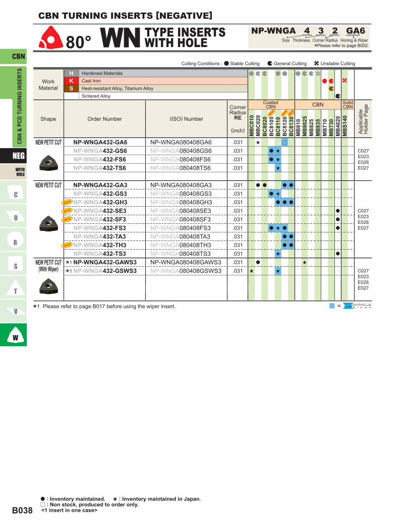
B038
NEG
CBN
NP-WNGA 4 3 2 GA6WN80°
*1
*1
HKS
CBN
MB
C01
0M
BC
020
BC
8020
BC
8105
BC
8110
BC
8120
BC
8130
MB
810
MB
8025
MB
825
MB
835
MB
710
MB
730
MB
4020
MB
S140
NP-WNGA432-GA6 NP-WNGA080408GA6 .031 s r
C027E023E026E027
NP-WNGA432-GS6 NP-WNGA080408GS6 .031 a s
NP-WNGA432-FS6 NP-WNGA080408FS6 .031 a s
NP-WNGA432-TS6 NP-WNGA080408TS6 .031 s
NP-WNGA432-GA3 NP-WNGA080408GA3 .031 a a a a
C027E023E026E027
NP-WNGA432-GS3 NP-WNGA080408GS3 .031 a s
NP-WNGA432-GH3 NP-WNGA080408GH3 .031 a a a
NP-WNGA432-SE3 NP-WNGA080408SE3 .031 a
NP-WNGA432-SF3 NP-WNGA080408SF3 .031 a
NP-WNGA432-FS3 NP-WNGA080408FS3 .031 a s a a
NP-WNGA432-TA3 NP-WNGA080408TA3 .031 a a
NP-WNGA432-TH3 NP-WNGA080408TH3 .031 a a
NP-WNGA432-TS3 NP-WNGA080408TS3 .031 s a
NP-WNGA432-GAWS3 NP-WNGA080408GAWS3 .031 a s
C027E023E026E027
NP-WNGA432-GSWS3 NP-WNGA080408GSWS3 .031 s s
=
CBN
& PC
D TU
RNIN
G IN
SERT
SCBN TURNING INSERTS [NEGATIVE]
TYPE INSERTS WITH HOLE Size Thickness Corner Radius Honing & Wiper
*Please refer to page B002.
NEW PETIT CUT
NEW PETIT CUT
NEW PETIT CUT(With Wiper)
*1 Please refer to page B017 before using the wiper insert.
Cutting Conditions : Stable Cutting General Cutting Unstable Cutting
Work Material
Shape Order Number (ISO) Number
Corner Radius
RE
(inch)
Coated CBN
Hardened MaterialsCast IronHeat-resistant Alloy, Titanium AlloySintered Alloy
a : Inventory maintained. s : Inventory maintained in Japan.r : Non stock, produced to order only. <1 insert in one case>
WITH HOLE
Solid CBN
App
licab
le
Hol
der P
age

B039
CBN
NEG
55° DN DNG 3 2 2
80° CN CNG 4 3 1
B002B014
HKS
CBN
MB
C01
0M
BC
020
BC
8020
BC
8105
BC
8110
BC
8120
BC
8130
MB
810
MB
8025
MB
825
MB
835
MB
710
MB
730
MB
4020
MB
S140
CNG431 CNGN120404 .016 s
─CNG432 CNGN120408 .031 a
CNG433 CNGN120412 .047 a
HKS
CBN
MB
C01
0M
BC
020
BC
8020
BC
8105
BC
8110
BC
8120
BC
8130
MB
810
MB
8025
MB
825
MB
835
MB
710
MB
730
MB
4020
MB
S140
DNG322 DNGN110308 .031 s
─DNG323 DNGN110312 .047 s
CBN
& PC
D TU
RNIN
G IN
SERT
S
TYPE INSERTS WITHOUT HOLE Size Thickness Corner Radius
*Please refer to page B002.
Cutting Conditions : Stable Cutting General Cutting Unstable Cutting
TYPE INSERTS WITHOUT HOLE Size Thickness Corner Radius
*Please refer to page B002.
Cutting Conditions : Stable Cutting General Cutting Unstable Cutting
Work Material
Work Material
Shape
Shape
Order Number
Order Number
(ISO) Number
(ISO) Number
Corner Radius
RE
(inch)
Corner Radius
RE
(inch)
Coated CBN
Coated CBN
Hardened Materials
Hardened Materials
Cast Iron
Cast Iron
Heat-resistant Alloy, Titanium Alloy
Heat-resistant Alloy, Titanium Alloy
Sintered Alloy
Sintered Alloy
IDENTIFICATIONHONING
WITHOUT HOLE
Solid CBN
Solid CBN
App
licab
le
Hol
der P
age
App
licab
le
Hol
der P
age

B040
NEG
CBN
RNG 3 2RN
90° SN SNG 3 2 2
HKS
CBN
MB
C01
0M
BC
020
BC
8020
BC
8105
BC
8110
BC
8120
BC
8130
MB
810
MB
8025
MB
825
MB
835
MB
710
MB
730
MB
4020
MB
S140
RNG32 RNGN090300 0 a
─RNG42 RNGN120300 0 a
RNG43 RNGN120400 0 a
HKS
CBN
MB
C01
0M
BC
020
BC
8020
BC
8105
BC
8110
BC
8120
BC
8130
MB
810
MB
8025
MB
825
MB
835
MB
710
MB
730
MB
4020
MB
S140
SNG322 SNGN090308 .031 a
─
SNG323 SNGN090312 .047 a
SNG324 SNGN090316 .063 a
SNG432 SNGN120408 .031 a
SNG433 SNGN120412 .047 s
SNG434 SNGN120416 .063 a
SNG432 SNGN120408 .031 a
─SNG433 SNGN120412 .047 a
CBN
& PC
D TU
RNIN
G IN
SERT
S
Size
*Please refer to page B002.Thickness
TYPE INSERTS WITHOUT HOLE
Cutting Conditions : Stable Cutting General Cutting Unstable Cutting
TYPE INSERTS WITHOUT HOLE Size Thickness Corner Radius
*Please refer to page B002.
Cutting Conditions : Stable Cutting General Cutting Unstable Cutting
Work Material
Work Material
Shape
Shape
Order Number
Order Number
(ISO) Number
(ISO) Number
Corner Radius
RE
(inch)
Corner Radius
RE
(inch)
Coated CBN
Coated CBN
Hardened Materials
Hardened Materials
Cast Iron
Cast Iron
Heat-resistant Alloy, Titanium Alloy
Heat-resistant Alloy, Titanium Alloy
Sintered Alloy
Sintered Alloy
a : Inventory maintained. s : Inventory maintained in Japan. <1 insert in one case>
CBN TURNING INSERTS [NEGATIVE]
WITHOUT HOLE
Solid CBN
App
licab
le
Hol
der P
age
Solid CBN
App
licab
le
Hol
der P
age

B041
CBN
NEG
60° TN TNG 3 3 2
B002B014
HKS
CBN
MB
C01
0M
BC
020
BC
8020
BC
8105
BC
8110
BC
8120
BC
8130
MB
810
MB
8025
MB
825
MB
835
MB
710
MB
730
MB
4020
MB
S140
TNG332 TNGN160408 .031 a
─TNG333 TNGN160412 .047 a
TNG334 TNGN160416 .063 a
TNG331 TNGN160404 .016 a
─TNG332 TNGN160408 .031 a
CBN
& PC
D TU
RNIN
G IN
SERT
S
TYPE INSERTS WITHOUT HOLE Size Thickness Corner Radius
*Please refer to page B002.
Cutting Conditions : Stable Cutting General Cutting Unstable Cutting
Work Material
Shape Order Number (ISO) Number
Corner Radius
RE
(inch)
Coated CBN
Hardened MaterialsCast IronHeat-resistant Alloy, Titanium AlloySintered Alloy
IDENTIFICATIONHONING
WITHOUT HOLE
Solid CBN
App
licab
le
Hol
der P
age

B042
CBN80°
NP-CCGB 2 1.5 1 GA2CC
POSI 7º
HKS
CBN
MB
C01
0M
BC
020
BC
8020
BC
8105
BC
8110
BC
8120
BC
8130
MB
810
MB
8025
MB
835
MB
710
MB
730
MB
4020
NP-CCGB21.51-GA2 NP-CCGB060204GA2 .016 s a C030D012E006E012E013E040
NP-CCGW21.50.5-GA2 NP-CCGW060202GA2 .008 a a a a
C030D008D012E012E013E040
NP-CCGW21.51-GA2 NP-CCGW060204GA2 .016 a a a a a
NP-CCGW21.52-GA2 NP-CCGW060208GA2 .031 a a a a a
NP-CCGW32.50.5-GA2 NP-CCGW09T302GA2 .008 a a a a
NP-CCGW32.51-GA2 NP-CCGW09T304GA2 .016 a a a a a
NP-CCGW32.52-GA2 NP-CCGW09T308GA2 .031 a a a a a
NP-CCGW32.51-GH2 NP-CCGW09T304GH2 .016 a a a
NP-CCGW32.52-GH2 NP-CCGW09T308GH2 .031 a a a
NP-CCGW21.50.5-GS2 NP-CCGW060202GS2 .008 a a a a
NP-CCGW21.51-GS2 NP-CCGW060204GS2 .016 a a a a a
NP-CCGW21.52-GS2 NP-CCGW060208GS2 .031 a a a a
NP-CCGW32.50.5-GS2 NP-CCGW09T302GS2 .008 a a a a
NP-CCGW32.51-GS2 NP-CCGW09T304GS2 .016 a a a a a
NP-CCGW32.52-GS2 NP-CCGW09T308GS2 .031 a a a a a
NP-CCGW21.50.5-SE2 NP-CCGW060202SE2 .008 a
NP-CCGW21.51-SE2 NP-CCGW060204SE2 .016 a
NP-CCGW21.52-SE2 NP-CCGW060208SE2 .031 a
NP-CCGW32.50.5-SE2 NP-CCGW09T302SE2 .008 a
NP-CCGW32.51-SE2 NP-CCGW09T304SE2 .016 a
NP-CCGW32.52-SE2 NP-CCGW09T308SE2 .031 a
NP-CCGW21.50.5-SF2 NP-CCGW060202SF2 .008 a
NP-CCGW21.51-SF2 NP-CCGW060204SF2 .016 a
NP-CCGW21.52-SF2 NP-CCGW060208SF2 .031 a
NP-CCGW32.50.5-SF2 NP-CCGW09T302SF2 .008 a
NP-CCGW32.51-SF2 NP-CCGW09T304SF2 .016 a
NP-CCGW32.52-SF2 NP-CCGW09T308SF2 .031 a
NP-CCGW32.50.5-GN2 NP-CCGW09T302GN2 .008 a
NP-CCGW32.51-GN2 NP-CCGW09T304GN2 .016 a
NP-CCGW32.52-GN2 NP-CCGW09T308GN2 .031 a
NP-CCGW21.50.5-FA2 NP-CCGW060202FA2 .008 a a
NP-CCGW21.51-FA2 NP-CCGW060204FA2 .016 a a
NP-CCGW21.52-FA2 NP-CCGW060208FA2 .031 a a
NP-CCGW32.51-FA2 NP-CCGW09T304FA2 .016 a a
NP-CCGW32.52-FA2 NP-CCGW09T308FA2 .031 a a
=
CBN
& PC
D TU
RNIN
G IN
SERT
S
a : Inventory maintained. s : Inventory maintained in Japan. <1 insert in one case>
TYPE INSERTS WITH HOLE *Please refer to page B002.
Size Thickness Corner Radius Honing & Wiper
Cutting Conditions : Stable Cutting General Cutting Unstable Cutting
Work Material
Shape
NEW PETIT CUT
NEW PETIT CUT
Order Number (ISO) Number
Corner Radius
RE
(inch)
Hardened MaterialsCast IronHeat-resistant Alloy, Titanium AlloySintered Alloy
Coated CBN
CBN TURNING INSERTS [POSITIVE]
WITH HOLE
App
licab
le
Hol
der P
age

B043
CBN
B002B014
POSI 7º
HKS
CBN
MB
C01
0M
BC
020
BC
8020
BC
8105
BC
8110
BC
8120
BC
8130
MB
810
MB
8025
MB
835
MB
710
MB
730
MB
4020
NP-CCGW21.50.5-FS2 NP-CCGW060202FS2 .008 s a a
C030D008D012E012E013E040
NP-CCGW21.51-FS2 NP-CCGW060204FS2 .016 s a a
NP-CCGW21.52-FS2 NP-CCGW060208FS2 .031 a a
NP-CCGW32.50.5-FS2 NP-CCGW09T302FS2 .008 s a a a
NP-CCGW32.51-FS2 NP-CCGW09T304FS2 .016 s a a a a
NP-CCGW32.52-FS2 NP-CCGW09T308FS2 .031 s a a a a
NP-CCGW21.50.5-TA2 NP-CCGW060202TA2 .008 a a
NP-CCGW21.51-TA2 NP-CCGW060204TA2 .016 a a
NP-CCGW21.52-TA2 NP-CCGW060208TA2 .031 a a
NP-CCGW32.50.5-TA2 NP-CCGW09T302TA2 .008 a
NP-CCGW32.51-TA2 NP-CCGW09T304TA2 .016 a a a
NP-CCGW32.52-TA2 NP-CCGW09T308TA2 .031 a a a
NP-CCGW32.51-TH2 NP-CCGW09T304TH2 .016 a a
NP-CCGW32.52-TH2 NP-CCGW09T308TH2 .031 a a
NP-CCGW21.50.5-TS2 NP-CCGW060202TS2 .008 a
NP-CCGW21.51-TS2 NP-CCGW060204TS2 .016 a
NP-CCGW21.52-TS2 NP-CCGW060208TS2 .031 a
NP-CCGW32.50.5-TS2 NP-CCGW09T302TS2 .008 a
NP-CCGW32.51-TS2 NP-CCGW09T304TS2 .016 a
NP-CCGW32.52-TS2 NP-CCGW09T308TS2 .031 a
NP-CCGW32.51-FSWS2 NP-CCGW09T304FSWS2 .016 a a a
C030D008D012E012E013E040
NP-CCGW32.52-FSWS2 NP-CCGW09T308FSWS2 .031 a a a
NP-CCGW32.51-GAWS2 NP-CCGW09T304GAWS2 .016 a a a
NP-CCGW32.52-GAWS2 NP-CCGW09T308GAWS2 .031 a a a s
NP-CCGW32.51-GSWS2 NP-CCGW09T304GSWS2 .016 a a
NP-CCGW32.52-GSWS2 NP-CCGW09T308GSWS2 .031 a a a
BF-CCGT32.51-TA2 BF-CCGT09T304TA2 .016 a C030D008D012E012E013E040
BF-CCGT32.52-TA2 BF-CCGT09T308TA2 .031 a
BF-CCGT32.51-TS2 BF-CCGT09T304TS2 .016 s
BF-CCGT32.52-TS2 BF-CCGT09T308TS2 .031 s
BF-CCGW32.51-TS2 BF-CCGW09T304TS2 .016 s C030D008D012E012E013E040
BF-CCGW32.52-TS2 BF-CCGW09T308TS2 .031 s
*1
*1
*1
*1
*1
*1
=
CBN
& PC
D TU
RNIN
G IN
SERT
S
Cutting Conditions : Stable Cutting General Cutting Unstable Cutting
NEW PETIT CUT
NEW PETIT CUT(With Wiper)
NEW PETIT CUT
*1 Please refer to page B017 before using the wiper insert.
NEW PETIT CUT
(With breaker)
Work Material
Shape Order Number (ISO) Number
Corner Radius
RE
(inch)
Hardened MaterialsCast IronHeat-resistant Alloy, Titanium AlloySintered Alloy
Coated CBN
IDENTIFICATIONHONING
WITH HOLE
App
licab
le
Hol
der P
age

B044
CBN80°
BM-CCGT 3 2.5 1 TA2CC
POSI 7º
HKS
CBN
MB
C01
0M
BC
020
BC
8020
BC
8105
BC
8110
BC
8120
BC
8130
MB
810
MB
8025
MB
835
MB
710
MB
730
MB
4020
BM-CCGT32.51-TA2 BM-CCGT09T304TA2 .016 a C030D008D012E012E013E020
BM-CCGT32.52-TA2 BM-CCGT09T308TA2 .031 a
NP-CCGW04T002GS NP-CCGW04T002GS .008 a
E012E029
NP-CCGW04T004GS NP-CCGW04T004GS .016 a
NP-CCGW03S102FA NP-CCGW03S102FA .008 a
E012E029
NP-CCGW04T002FA NP-CCGW04T002FA .008 a
NP-CCGW03S102FS NP-CCGW03S102FS .008 a
NP-CCGW03S104FS NP-CCGW03S104FS .016 a a
NP-CCGW03S102GS NP-CCGW03S102GS .008 a
NP-CCGW03S104GS NP-CCGW03S104GS .016 a
NP-CCGW04T002FS NP-CCGW04T002FS .008 a
NP-CCGW04T004FS NP-CCGW04T004FS .016 a a
NP-CCGW03S102FS NP-CCGW03S102FS .008 a
NP-CCGW03S104FS NP-CCGW03S104FS .016 a a
NP-CCGW04T002FS NP-CCGW04T002FS .008 a
NP-CCGW04T004FS NP-CCGW04T004FS .016 a a
CCGW21.50.5FS CCGW060202FS .008 s C030D008D012E012E013E040
CCGW21.51FS CCGW060204FS .016 s
CCGW21.52FS CCGW060208FS .031 s
CCGW32.51FS CCGW09T304FS .016 s
CCGW32.52FS CCGW09T308FS .031 s
CCGW32.51 CCGW09T304 .016 a C030D008D012E012E013E040
CCGW32.52 CCGW09T308 .031 a
CCGW432 CCGW120408 .031 a
*1*1
=
CBN
& PC
D TU
RNIN
G IN
SERT
S
a : Inventory maintained. s : Inventory maintained in Japan.r : Non stock, produced to order only. <1 insert in one case>
Cutting Conditions : Stable Cutting General Cutting Unstable Cutting
*1 Diameter of inscribed circle is non-ISO standard. (For SCLC type)
NEW PETIT CUT
NEW PETIT CUT
NEW PETIT CUT
(With breaker)
Work Material
Shape Order Number (ISO) Number
Corner Radius
RE
(inch)
Hardened MaterialsCast IronHeat-resistant Alloy, Titanium AlloySintered Alloy
Coated CBN
TYPE INSERTS WITH HOLE *Please refer to page B002.
Size Thickness Corner Radius Honing & Wiper
CBN TURNING INSERTS [POSITIVE]
WITH HOLE
App
licab
le
Hol
der P
age

B045
CBN80° CP NP-CPGB 2.5 1.5 1 GA2
B002B014
POSI 11º
HKS
CBN
MB
C01
0M
BC
020
BC
8020
BC
8105
BC
8110
BC
8120
BC
8130
MB
810
MB
8025
MB
835
MB
710
MB
730
MB
4020
NP-CPGB2.51.51-GA2 NP-CPGB080204GA2 .016 s s s a
E006E007E041
NP-CPGB2.51.52-GA2 NP-CPGB080208GA2 .031 s s s a
NP-CPGB2.51.53-GA2 NP-CPGB080212GA2 .047 s a
NP-CPGB320.5-GA2 NP-CPGB090302GA2 .008 a
NP-CPGB321-GA2 NP-CPGB090304GA2 .016 s a a a
NP-CPGB322-GA2 NP-CPGB090308GA2 .031 s a a
NP-CPGB323-GA2 NP-CPGB090312GA2 .047 a a
NP-CPGB2.51.51-GS2 NP-CPGB080204GS2 .016 a s
NP-CPGB2.51.52-GS2 NP-CPGB080208GS2 .031 a s
NP-CPGB320.5-GS2 NP-CPGB090302GS2 .008 a a
NP-CPGB321-GS2 NP-CPGB090304GS2 .016 a s
NP-CPGB322-GS2 NP-CPGB090308GS2 .031 a s
NP-CPGB323-GA2 NP-CPGB090312GA2 .047 a a
NP-CPGB2.51.50.5-SE2 NP-CPGB080202SE2 .008 a
NP-CPGB2.51.51-SE2 NP-CPGB080204SE2 .016 a
NP-CPGB320.5-SE2 NP-CPGB090302SE2 .008 a
NP-CPGB321-SE2 NP-CPGB090304SE2 .016 a
NP-CPGB322-SE2 NP-CPGB090308SE2 .031 a
NP-CPGB2.51.50.5-FS2 NP-CPGB080202FS2 .008 s
NP-CPGB2.51.51-FS2 NP-CPGB080204FS2 .016 s s r s
NP-CPGB2.51.52-FS2 NP-CPGB080208FS2 .031 s s r
NP-CPGB320.5-FS2 NP-CPGB090302FS2 .008 a a a
NP-CPGB321-FS2 NP-CPGB090304FS2 .016 a a a
NP-CPGB322-FS2 NP-CPGB090308FS2 .031 a a a
NP-CPGB323-FS2 NP-CPGB090312FS2 .047 a
NP-CPGB2.51.51-TA2 NP-CPGB080204TA2 .016 a
NP-CPGB2.51.52-TA2 NP-CPGB080208TA2 .031 a
NP-CPGB2.51.53-TA2 NP-CPGB080212TA2 .047 a
NP-CPGB321-TA2 NP-CPGB090304TA2 .016 a a
NP-CPGB322-TA2 NP-CPGB090308TA2 .031 a a
NP-CPGB323-TA2 NP-CPGB090312TA2 .047 a a
=
CBN
& PC
D TU
RNIN
G IN
SERT
S
TYPE INSERTS WITH HOLE Size Thickness Corner Radius Honing & Wiper
*Please refer to page B002.
Cutting Conditions : Stable Cutting General Cutting Unstable Cutting
NEW PETIT CUT
Work Material
Shape Order Number (ISO) Number
Corner Radius
RE
(inch)
Hardened MaterialsCast IronHeat-resistant Alloy, Titanium AlloySintered Alloy
Coated CBN
IDENTIFICATIONHONING
WITH HOLE
App
licab
le
Hol
der P
age

B046
CBN
NP-DCGW 2 1.5 0.5 GA2DC55°
POSI 7º
HKS
CBN
MB
C01
0M
BC
020
BC
8020
BC
8105
BC
8110
BC
8120
BC
8130
MB
810
MB
8025
MB
835
MB
710
MB
730
MB
4020
NP-DCGW21.50.5-GA2 NP-DCGW070202GA2 .008 a s a a
C031C032D009D013D040E008E013E014E042E043
NP-DCGW21.51-GA2 NP-DCGW070204GA2 .016 a a a a a
NP-DCGW21.52-GA2 NP-DCGW070208GA2 .031 a a a a
NP-DCGW32.50.5-GA2 NP-DCGW11T302GA2 .008 a s a a
NP-DCGW32.51-GA2 NP-DCGW11T304GA2 .016 a a a a a
NP-DCGW32.52-GA2 NP-DCGW11T308GA2 .031 a a a a a
NP-DCGW32.51-GH2 NP-DCGW11T304GH2 .016 a a a
NP-DCGW32.52-GH2 NP-DCGW11T308GH2 .031 a a a
NP-DCGW21.50.5-GS2 NP-DCGW070202GS2 .008 a a
NP-DCGW21.51-GS2 NP-DCGW070204GS2 .016 a a a
NP-DCGW21.52-GS2 NP-DCGW070208GS2 .031 a a
NP-DCGW32.50.5-GS2 NP-DCGW11T302GS2 .008 s a a a
NP-DCGW32.51-GS2 NP-DCGW11T304GS2 .016 a a a a a a
NP-DCGW32.52-GS2 NP-DCGW11T308GS2 .031 a a a a a a
NP-DCGW21.51-SE2 NP-DCGW070204SE2 .016 a
NP-DCGW21.52-SE2 NP-DCGW070208SE2 .031 a
NP-DCGW32.50.5-SE2 NP-DCGW11T302SE2 .008 a
NP-DCGW32.51-SE2 NP-DCGW11T304SE2 .016 a
NP-DCGW32.52-SE2 NP-DCGW11T308SE2 .031 a
NP-DCGW21.51-SF2 NP-DCGW070204SF2 .016 a
NP-DCGW21.52-SF2 NP-DCGW070208SF2 .031 a
NP-DCGW32.50.5-SF2 NP-DCGW11T302SF2 .008 a
NP-DCGW32.51-SF2 NP-DCGW11T304SF2 .016 a
NP-DCGW32.52-SF2 NP-DCGW11T308SF2 .031 a
NP-DCGW21.50.5-GN2 NP-DCGW070202GN2 .008 a
NP-DCGW21.51-GN2 NP-DCGW070204GN2 .016 a
NP-DCGW21.52-GN2 NP-DCGW070208GN2 .031 a
NP-DCGW32.50.5-GN2 NP-DCGW11T302GN2 .008 a
NP-DCGW32.51-GN2 NP-DCGW11T304GN2 .016 a
NP-DCGW32.52-GN2 NP-DCGW11T308GN2 .031 a
NP-DCGW32.51-FA2 NP-DCGW11T304FA2 .016 a a
NP-DCGW32.52-FA2 NP-DCGW11T308FA2 .031 a a
NP-DCGW21.50.5-FS2 NP-DCGW070202FS2 .008 s a
NP-DCGW21.51-FS2 NP-DCGW070204FS2 .016 s a a a
NP-DCGW21.52-FS2 NP-DCGW070208FS2 .031 a a
NP-DCGW32.50.5-FS2 NP-DCGW11T302FS2 .008 s a a a
NP-DCGW32.51-FS2 NP-DCGW11T304FS2 .016 s a a a a
NP-DCGW32.52-FS2 NP-DCGW11T308FS2 .031 s a a a a
=
CBN
& PC
D TU
RNIN
G IN
SERT
SCBN TURNING INSERTS [POSITIVE]
a : Inventory maintained. s : Inventory maintained in Japan. <1 insert in one case>
NEW PETIT CUT
TYPE INSERTS WITH HOLE Size Thickness Corner Radius Honing & Wiper
*Please refer to page B002.
Cutting Conditions : Stable Cutting General Cutting Unstable Cutting
Work Material
Shape Order Number (ISO) Number
Corner Radius
RE
(inch)
Hardened MaterialsCast IronHeat-resistant Alloy, Titanium AlloySintered Alloy
Coated CBN
WITH HOLE
App
licab
le
Hol
der P
age

B047
CBN
B002B014
POSI 7º
HKS
CBN
MB
C01
0M
BC
020
BC
8020
BC
8105
BC
8110
BC
8120
BC
8130
MB
810
MB
8025
MB
835
MB
710
MB
730
MB
4020
NP-DCGW21.50.5-TA2 NP-DCGW070202TA2 .008 a
C031C032D009D013D040E008E013E014E042E043
NP-DCGW21.51-TA2 NP-DCGW070204TA2 .016 a a a
NP-DCGW21.52-TA2 NP-DCGW070208TA2 .031 a
NP-DCGW32.50.5-TA2 NP-DCGW11T302TA2 .008 a
NP-DCGW32.51-TA2 NP-DCGW11T304TA2 .016 a a a
NP-DCGW32.52-TA2 NP-DCGW11T308TA2 .031 a a a
NP-DCGW32.51-TH2 NP-DCGW11T304TH2 .016 a a
NP-DCGW32.52-TH2 NP-DCGW11T308TH2 .031 a a
NP-DCGW21.51-TS2 NP-DCGW070204TS2 .016 a
NP-DCGW21.52-TS2 NP-DCGW070208TS2 .031 a
NP-DCGW32.50.5-TS2 NP-DCGW11T302TS2 .008 a
NP-DCGW32.51-TS2 NP-DCGW11T304TS2 .016 a
NP-DCGW32.52-TS2 NP-DCGW11T308TS2 .031 a
BF-DCGT32.51-TA2 BF-DCGT11T304TA2 .016 aC031C032D009D013D040E008E013E014E042E043
BF-DCGT32.52-TA2 BF-DCGT11T308TA2 .031 a
BF-DCGT32.51-TS2 BF-DCGT11T304TS2 .016 s
BF-DCGT32.52-TS2 BF-DCGT11T308TS2 .031 s
BF-DCGW32.51-TS2 BF-DCGW11T304TS2 .016 sC031C032D009D013D040E008E013E014E042E043
BF-DCGW32.52-TS2 BF-DCGW11T308TS2 .031 s
BM-DCGT32.51-TA2 BM-DCGT11T304TA2 .016 aC031C032D009D013D040E008E013E014E042E043
BM-DCGT32.52-TA2 BM-DCGT11T308TA2 .031 a
DCGW21.51FS DCGW070204FS .016 sC031C032D009D013D040E008E013E014E042E043
DCGW21.52FS DCGW070208FS .031 s
DCGW32.51 DCGW11T304 .016 aC031C032D009D013D040E008E013E014E042E043
=
CBN
& PC
D TU
RNIN
G IN
SERT
S
Cutting Conditions : Stable Cutting General Cutting Unstable Cutting
NEW PETIT CUT
(With breaker)NEW PETIT CUT
(With breaker)
Work Material
Shape Order Number (ISO) Number
Corner Radius
RE
(inch)
Hardened MaterialsCast IronHeat-resistant Alloy, Titanium AlloySintered Alloy
Coated CBN
NEW PETIT CUT
(With breaker)
NEW PETIT CUT
IDENTIFICATIONHONING
WITH HOLE
App
licab
le
Hol
der P
age

B048
CBN60° TC NP-TCGW 1.8 1.5 0.5 GA3
POSI 7º
HKS
CBN
MB
C01
0M
BC
020
BC
8020
BC
8105
BC
8110
BC
8120
BC
8130
MB
810
MB
8025
MB
835
MB
710
MB
730
MB
4020
NP-TCGW1.81.50.5-GA3 NP-TCGW090202GA3 .008 a
C035E015E016E044
NP-TCGW1.81.51-GA3 NP-TCGW090204GA3 .016 a
NP-TCGW1.81.52-GA3 NP-TCGW090208GA3 .031 a
NP-TCGW21.50.5-GA3 NP-TCGW110202GA3 .008 a
NP-TCGW21.51-GA3 NP-TCGW110204GA3 .016 a a
NP-TCGW21.52-GA3 NP-TCGW110208GA3 .031 a a
NP-TCGW2.521-GA3 NP-TCGW130304GA3 .016 s
NP-TCGW2.522-GA3 NP-TCGW130308GA3 .031 s
NP-TCGW32.51-GA3 NP-TCGW16T304GA3 .016 a a
NP-TCGW32.52-GA3 NP-TCGW16T308GA3 .031 a
NP-TCGW1.81.51-GS3 NP-TCGW090204GS3 .016 s
NP-TCGW1.81.52-GS3 NP-TCGW090208GS3 .031 s
NP-TCGW21.50.5-GS3 NP-TCGW110202GS3 .008 a
NP-TCGW21.51-GS3 NP-TCGW110204GS3 .016 a
NP-TCGW21.52-GS3 NP-TCGW110208GS3 .031 a
NP-TCGW2.521-GS3 NP-TCGW130304GS3 .016 s
NP-TCGW2.522-GS3 NP-TCGW130308GS3 .031 s
NP-TCGW32.51-GS3 NP-TCGW16T304GS3 .016 a
NP-TCGW32.52-GS3 NP-TCGW16T308GS3 .031 a
NP-TCGW21.51-SE3 NP-TCGW110204SE3 .016 a
NP-TCGW21.52-SE3 NP-TCGW110208SE3 .031 a
NP-TCGW21.51-SF3 NP-TCGW110204SF3 .016 a
NP-TCGW21.52-SF3 NP-TCGW110208SF3 .031 a
NP-TCGW21.51-FA3 NP-TCGW110204FA3 .016 a a
NP-TCGW21.52-FA3 NP-TCGW110208FA3 .031 a a
NP-TCGW21.51-FS3 NP-TCGW110204FS3 .016 a
NP-TCGW21.52-FS3 NP-TCGW110208FS3 .031 a
NP-TCGW32.51-FS3 NP-TCGW16T304FS3 .016 a
NP-TCGW32.52-FS3 NP-TCGW16T308FS3 .031 a
NP-TCGW21.51-TS3 NP-TCGW110204TS3 .016 a
NP-TCGW21.52-TS3 NP-TCGW110208TS3 .031 a
TCGW1.81.51FS TCGW090204FS .016 sC035E015E016E044
TCGW1.81.52FS TCGW090208FS .031 s
TCGW21.51FS TCGW110204FS .016 s
TCGW21.52FS TCGW110208FS .031 s
=
CBN
& PC
D TU
RNIN
G IN
SERT
SCBN TURNING INSERTS [POSITIVE]
a : Inventory maintained. s : Inventory maintained in Japan. <1 insert in one case>
TYPE INSERTS WITH HOLE Size Thickness Corner Radius Honing & Wiper
*Please refer to page B002.
Cutting Conditions : Stable Cutting General Cutting Unstable Cutting
NEW PETIT CUT
Work Material
Shape Order Number (ISO) Number
Corner Radius
RE
(inch)
Hardened MaterialsCast IronHeat-resistant Alloy, Titanium AlloySintered Alloy
Coated CBN
WITH HOLE
App
licab
le
Hol
der P
age

B049
CBN
NP-TPGB 1.5 1.5 1 GA3TP60°
B002B014
POSI 11º
HKS
CBN
MB
C01
0M
BC
020
BC
8020
BC
8105
BC
8110
BC
8120
BC
8130
MB
810
MB
8025
MB
835
MB
710
MB
730
MB
4020
NP-TPGB1.51.51-GA3 NP-TPGB080204GA3 .016 a a a
E007E045
NP-TPGB1.51.52-GA3 NP-TPGB080208GA3 .031 a a
NP-TPGB1.81.51-GA3 NP-TPGB090204GA3 .016 a s a a
NP-TPGB1.81.52-GA3 NP-TPGB090208GA3 .031 a s a
NP-TPGB220.5-GA3 NP-TPGB110302GA3 .008 s
NP-TPGB221-GA3 NP-TPGB110304GA3 .016 s s s a
NP-TPGB222-GA3 NP-TPGB110308GA3 .031 s s s a
NP-TPGB321-GA3 NP-TPGB160304GA3 .016 s s s a a
NP-TPGB322-GA3 NP-TPGB160308GA3 .031 s a s a
NP-TPGB321-GH3 NP-TPGB160304GH3 .016 a a a
NP-TPGB322-GH3 NP-TPGB160308GH3 .031 a a a
NP-TPGB1.51.51-GS3 NP-TPGB080204GS3 .016 a s
NP-TPGB1.51.52-GS3 NP-TPGB080208GS3 .031 a s
NP-TPGB1.81.51-GS3 NP-TPGB090204GS3 .016 a s
NP-TPGB1.81.52-GS3 NP-TPGB090208GS3 .031 a s
NP-TPGB220.5-GS3 NP-TPGB110302GS3 .008 a a
NP-TPGB221-GS3 NP-TPGB110304GS3 .016 a s
NP-TPGB222-GS3 NP-TPGB110308GS3 .031 a s
NP-TPGB321-GS3 NP-TPGB160304GS3 .016 a s
NP-TPGB322-GS3 NP-TPGB160308GS3 .031 a s
NP-TPGB1.81.50.5-SE3 NP-TPGB090202SE3 .008 a
NP-TPGB1.81.51-SE3 NP-TPGB090204SE3 .016 a
NP-TPGB220.5-SE3 NP-TPGB110302SE3 .008 a
NP-TPGB221-SE3 NP-TPGB110304SE3 .016 a
NP-TPGB222-SE3 NP-TPGB110308SE3 .031 a
NP-TPGB1.81.50.5-SF3 NP-TPGB090202SF3 .008 a
NP-TPGB1.81.51-SF3 NP-TPGB090204SF3 .016 a
NP-TPGB220.5-SF3 NP-TPGB110302SF3 .008 a
NP-TPGB221-SF3 NP-TPGB110304SF3 .016 a
NP-TPGB222-SF3 NP-TPGB110308SF3 .031 a
NP-TPGB1.81.50.5-FS3 NP-TPGB090202FS3 .008 a
NP-TPGB1.81.51-FS3 NP-TPGB090204FS3 .016 a
NP-TPGB220.5-FS3 NP-TPGB110302FS3 .008 a a a
NP-TPGB221-FS3 NP-TPGB110304FS3 .016 s a s s a
NP-TPGB222-FS3 NP-TPGB110308FS3 .031 s a s s a
NP-TPGB321-FS3 NP-TPGB160304FS3 .016 s s
NP-TPGB322-FS3 NP-TPGB160308FS3 .031 s s
=
CBN
& PC
D TU
RNIN
G IN
SERT
S
TYPE INSERTS WITH HOLE *Please refer to page B002.
Honing & WiperSize Thickness Corner Radius
Cutting Conditions : Stable Cutting General Cutting Unstable Cutting
NEW PETIT CUT
Work Material
Shape Order Number (ISO) Number
Corner Radius
RE
(inch)
Hardened MaterialsCast IronHeat-resistant Alloy, Titanium AlloySintered Alloy
Coated CBN
IDENTIFICATIONHONING
WITH HOLE
App
licab
le
Hol
der P
age

B050
CBN
NP-TPGB 1.5 1.5 1 TA3TP60°
POSI 11º
=
HKS
CBN
MB
C01
0M
BC
020
BC
8020
BC
8105
BC
8110
BC
8120
BC
8130
MB
810
MB
8025
MB
835
MB
710
MB
730
MB
4020
NP-TPGB1.51.51-TA3 NP-TPGB080204TA3 .016 a
E007E045
NP-TPGB1.51.52-TA3 NP-TPGB080208TA3 .031 a
NP-TPGB1.81.51-TA3 NP-TPGB090204TA3 .016 a
NP-TPGB1.81.52-TA3 NP-TPGB090208TA3 .031 a
NP-TPGB221-TA3 NP-TPGB110304TA3 .016 s a
NP-TPGB222-TA3 NP-TPGB110308TA3 .031 s a
NP-TPGB321-TA3 NP-TPGB160304TA3 .016 s a
NP-TPGB322-TA3 NP-TPGB160308TA3 .031 s a
NP-TPGB321-TH3 NP-TPGB160304TH3 .016 a a
NP-TPGB322-TH3 NP-TPGB160308TH3 .031 a a
NP-TPGX1.51.50.5-GS3 NP-TPGX080202GS3 .008 s
E007E045
NP-TPGX1.51.51-GS3 NP-TPGX080204GS3 .016 s
NP-TPGX1.81.50.5-GS3 NP-TPGX090202GS3 .008 s
NP-TPGX1.81.51-GS3 NP-TPGX090204GS3 .016 s
NP-TPGX221-GS3 NP-TPGX110304GS3 .016 s
NP-TPGX222-GS3 NP-TPGX110308GS3 .031 s
NP-TPGX222-TA3 NP-TPGX110308TA3 .031 a
NP-TPGX1.51.50.5F NP-TPGX080202F .008 s
E007E045
NP-TPGX1.51.51F NP-TPGX080204F .016 s
NP-TPGX1.81.50.5F NP-TPGX090202F .008 s
NP-TPGX1.81.51F NP-TPGX090204F .016 s
TPGX1.51.50.5 TPGX080202 .008 s s
E007E045
TPGX1.51.51 TPGX080204 .016 s s s
TPGX1.81.50.5 TPGX090202 .008 s s
TPGX1.81.51 TPGX090204 .016 s s s
TPGX221 TPGX110304 .016 a a a
TPGX222 TPGX110308 .031 a a a
TPGX321 TPGX160304 .016 a
TPGX322 TPGX160308 .031 a
CBN
& PC
D TU
RNIN
G IN
SERT
SCBN TURNING INSERTS [POSITIVE]
a : Inventory maintained. s : Inventory maintained in Japan. <1 insert in one case>
NEW PETIT CUT
NEW PETIT CUT
NEW PETIT CUT
Cutting Conditions : Stable Cutting General Cutting Unstable Cutting
Work Material
Shape Order Number (ISO) Number
Corner Radius
RE
(inch)
Hardened MaterialsCast IronHeat-resistant Alloy, Titanium AlloySintered Alloy
Coated CBN
TYPE INSERTS WITH HOLE *Please refer to page B002.
Honing & WiperSize Thickness Corner Radius
WITH HOLE
App
licab
le
Hol
der P
age

B051
CBN
NP-VBGW 3 3 1 GA2VB35°
B002B014
POSI 5º
HKS
CBN
MB
C01
0M
BC
020
BC
8020
BC
8105
BC
8110
BC
8120
BC
8130
MB
810
MB
8025
MB
835
MB
710
MB
730
MB
4020
NP-VBGW220.5-GA2 NP-VBGW110302GA2 .008 a
C028C029D010D011D014D015E009E010H013
NP-VBGW221-GA2 NP-VBGW110304GA2 .016 a a
NP-VBGW222-GA2 NP-VBGW110308GA2 .031 a a
NP-VBGW330.5-GA2 NP-VBGW160402GA2 .008 a
NP-VBGW331-GA2 NP-VBGW160404GA2 .016 a a a a a
NP-VBGW332-GA2 NP-VBGW160408GA2 .031 a a a a a
NP-VBGW331-GH2 NP-VBGW160404GH2 .016 a a a
NP-VBGW332-GH2 NP-VBGW160408GH2 .031 a a a
NP-VBGW220.5-GS2 NP-VBGW110302GS2 .008 a a
NP-VBGW221-GS2 NP-VBGW110304GS2 .016 a a a
NP-VBGW222-GS2 NP-VBGW110308GS2 .031 a a a
NP-VBGW330.5-GS2 NP-VBGW160402GS2 .008 a a
NP-VBGW331-GS2 NP-VBGW160404GS2 .016 a a a a
NP-VBGW332-GS2 NP-VBGW160408GS2 .031 a a a a
NP-VBGW221-SE2 NP-VBGW110304SE2 .016 a
NP-VBGW222-SE2 NP-VBGW110308SE2 .031 a
NP-VBGW331-SE2 NP-VBGW160404SE2 .016 a
NP-VBGW332-SE2 NP-VBGW160408SE2 .031 a
NP-VBGW221-SF2 NP-VBGW110304SF2 .016 a
NP-VBGW222-SF2 NP-VBGW110308SF2 .031 a
NP-VBGW331-SF2 NP-VBGW160404SF2 .016 a
NP-VBGW332-SF2 NP-VBGW160408SF2 .031 a
NP-VBGW220.5-FS2 NP-VBGW110302FS2 .008 a
NP-VBGW221-FS2 NP-VBGW110304FS2 .016 a a
NP-VBGW222-FS2 NP-VBGW110308FS2 .031 a a
NP-VBGW330.5-FS2 NP-VBGW160402FS2 .008 a
NP-VBGW331-FS2 NP-VBGW160404FS2 .016 s a a
NP-VBGW332-FS2 NP-VBGW160408FS2 .031 s a a
NP-VBGW221-TA2 NP-VBGW110304TA2 .016 a
NP-VBGW222-TA2 NP-VBGW110308TA2 .031 a
NP-VBGW331-TA2 NP-VBGW160404TA2 .016 a a
NP-VBGW332-TA2 NP-VBGW160408TA2 .031 a a
NP-VBGW331-TH2 NP-VBGW160404TH2 .016 a a
NP-VBGW332-TH2 NP-VBGW160408TH2 .031 a a
NP-VBGW221-TS2 NP-VBGW110304TS2 .016 a
NP-VBGW222-TS2 NP-VBGW110308TS2 .031 a
NP-VBGW331-TS2 NP-VBGW160404TS2 .016 a
NP-VBGW332-TS2 NP-VBGW160408TS2 .031 a
=
CBN
& PC
D TU
RNIN
G IN
SERT
S
TYPE INSERTS WITH HOLE *Please refer to page B002.
Honing & WiperCorner RadiusSize Thickness
Cutting Conditions : Stable Cutting General Cutting Unstable Cutting
NEW PETIT CUT
Work Material
Shape Order Number (ISO) Number
Corner Radius
RE
(inch)
Hardened MaterialsCast IronHeat-resistant Alloy, Titanium AlloySintered Alloy
Coated CBN
IDENTIFICATIONHONING
WITH HOLE
App
licab
le
Hol
der P
age

B052
CBN35° VC NP-VCGW 3 3 1 GA2
POSI 7º
HKS
CBN
MB
C01
0M
BC
020
BC
8020
BC
8105
BC
8110
BC
8120
BC
8130
MB
810
MB
8025
MB
835
MB
710
MB
730
MB
4020
NP-VCGW331-GA2 NP-VCGW160404GA2 .016 a s a a a
C036E016E017E046
NP-VCGW332-GA2 NP-VCGW160408GA2 .031 a s a a a
NP-VCGW331-GH2 NP-VCGW160404GH2 .016 a a a
NP-VCGW332-GH2 NP-VCGW160408GH2 .031 a a a
NP-VCGW331-GS2 NP-VCGW160404GS2 .016 a a
NP-VCGW332-GS2 NP-VCGW160408GS2 .031 a a
NP-VCGW331-FS2 NP-VCGW160404FS2 .016 s a a
NP-VCGW332-FS2 NP-VCGW160408FS2 .031 s a a
NP-VCGW331-TA2 NP-VCGW160404TA2 .016 a a
NP-VCGW332-TA2 NP-VCGW160408TA2 .031 a a
NP-VCGW331-TH2 NP-VCGW160404TH2 .016 a a
NP-VCGW332-TH2 NP-VCGW160408TH2 .031 a a
NP-VCGW331-TS2 NP-VCGW160404TS2 .016 a
NP-VCGW332-TS2 NP-VCGW160408TS2 .031 a
=
CBN
& PC
D TU
RNIN
G IN
SERT
SCBN TURNING INSERTS [POSITIVE]
a : Inventory maintained. s : Inventory maintained in Japan. <1 insert in one case>
TYPE INSERTS WITH HOLE Size Thickness Corner Radius Honing & Wiper
*Please refer to page B002.
Cutting Conditions : Stable Cutting General Cutting Unstable Cutting
NEW PETIT CUT
Work Material
Shape Order Number (ISO) Number
Corner Radius
RE
(inch)
Hardened MaterialsCast IronHeat-resistant Alloy, Titanium AlloySintered Alloy
Coated CBN
WITH HOLE
App
licab
le
Hol
der P
age

B053
CBN
NP-WCGW 1.5 1.5 0.5 GA3WC80°
B002B014
POSI 7º
HKS
CBN
MB
C01
0M
BC
020
BC
8020
BC
8105
BC
8110
BC
8120
BC
8130
MB
810
MB
8025
MB
835
MB
710
MB
730
MB
4020
NP-WCGW1.51.50.5-GA3 NP-WCGWL30202GA3 .008 a
C037E017─020E047
NP-WCGW1.51.51-GA3 NP-WCGWL30204GA3 .016 a
NP-WCGW21.50.5-GA3 NP-WCGW040202GA3 .008 a
NP-WCGW21.51-GA3 NP-WCGW040204GA3 .016 a
NP-WCGW32.51-GA3 NP-WCGW06T304GA3 .016 a
NP-WCGW32.52-GA3 NP-WCGW06T308GA3 .031 a
NP-WCGW1.51.50.5-GS3 NP-WCGWL30202GS3 .008 a
NP-WCGW1.51.51-GS3 NP-WCGWL30204GS3 .016 a
NP-WCGW21.50.5-GS3 NP-WCGW040202GS3 .008 a
NP-WCGW21.51-GS3 NP-WCGW040204GS3 .016 a
NP-WCGW32.51-GS3 NP-WCGW06T304GS3 .016 a
NP-WCGW32.52-GS3 NP-WCGW06T308GS3 .031 a
CBN
& PC
D TU
RNIN
G IN
SERT
S
TYPE INSERTS WITH HOLE Honing & WiperCorner Radius
*Please refer to page B002.Size Thickness
Cutting Conditions : Stable Cutting General Cutting Unstable Cutting
Work Material
Shape Order Number (ISO) Number
Corner Radius
RE
(inch)
Hardened MaterialsCast IronHeat-resistant Alloy, Titanium AlloySintered Alloy
Coated CBN
NEW PETIT CUT
IDENTIFICATIONHONING
WITH HOLE
App
licab
le
Hol
der P
age

B054
CBNRTG
POSI 5º6º
HKS
CBN
MB
825 IC L17 S D4
RTG05A RTG05A s .197 .138 .295 .098
─
RTG06A RTG06A s .236 .138 .295 .138RTG07A RTG07A s .276 .197 .433 .138RTG08A RTG08A s .315 .197 .433 .177RTG10A RTG10A s .394 .256 .551 .217
IC
D4
SL17
CBN
& PC
D TU
RNIN
G IN
SERT
SCBN TURNING INSERTS [POSITIVE]
a : Inventory maintained. s : Inventory maintained in Japan. <1 insert in one case>
Hardened MaterialsCast IronHeat-resistant Alloy, Titanium Alloy
TYPE INSERTS WITHOUT HOLE
Work Material
Shape Order Number (ISO) Number
Dimensions (inch)
Cutting Conditions : Stable Cutting General Cutting Unstable Cutting
App
licab
le
Hol
der P
age
WITHOUT HOLE

B055
CBN
SPG 3 2 1 SP90°
B002B014
POSI 11º
HKS
CBN
MB
C01
0M
BC
020
BC
8020
MB
8025
MB
835
MB
710
MB
730
MB
4020
SPG321 SPGN090304 .016 a
─SPG322 SPGN090308 .031 a
SPG421 SPGN120304 .016 a s
SPG422 SPGN120308 .031 a s
CBN
& PC
D TU
RNIN
G IN
SERT
S
TYPE INSERTS WITHOUT HOLE *Please refer to page B002.
Corner RadiusSize Thickness
Cutting Conditions : Stable Cutting General Cutting Unstable Cutting
Work Material
Shape Order Number (ISO) Number
Corner Radius
RE
(inch)
Coated CBN
Applicable Holder Page
Hardened Materials
Sintered AlloyHeat-resistant Alloy, Titanium AlloyCast Iron
IDENTIFICATIONHONING
WITHOUT HOLE

B056
CBN60° TB TBG 1.2 1 1
POSI 5º
11º
HKS
CBN
MB
C01
0M
BC
020
BC
8020
MB
810
MB
8025
MB
835
MB
710
MB
730
MB
4020
TBG1.211 TBGN060104 .016 s s
─TBG1.212 TBGN060108 .031 s s
CBN
& PC
D TU
RNIN
G IN
SERT
SCBN TURNING INSERTS [POSITIVE]
TYPE INSERTS WITHOUT HOLE Size Thickness Corner Radius
*Please refer to page B002.
Cutting Conditions : Stable Cutting General Cutting Unstable Cutting
Work Material
Shape Order Number (ISO) Number
Corner Radius
RE
(inch)
Hardened MaterialsCast Iron
Sintered AlloyHeat-resistant Alloy, Titanium Alloy
Coated CBN
Applicable Holder Page
a : Inventory maintained. s : Inventory maintained in Japan. <1 insert in one case>
WITHOUT HOLE
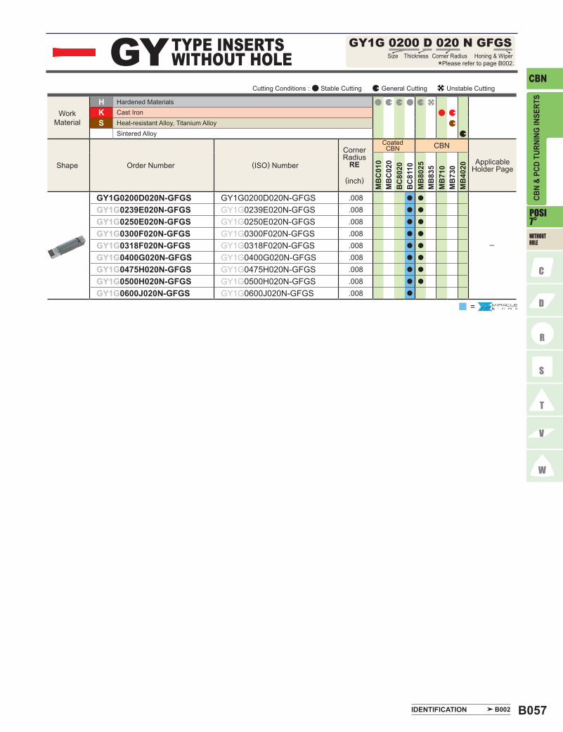
B057
CBNGY GY1G 0200 D 020 N GFGS
B002
POSI 7º
HKS
CBN
MB
C01
0M
BC
020
BC
8020
BC
8110
MB
8025
MB
835
MB
710
MB
730
MB
4020
GY1G0200D020N-GFGS GY1G0200D020N-GFGS .008 a a
─
GY1G0239E020N-GFGS GY1G0239E020N-GFGS .008 a a
GY1G0250E020N-GFGS GY1G0250E020N-GFGS .008 a a
GY1G0300F020N-GFGS GY1G0300F020N-GFGS .008 a a
GY1G0318F020N-GFGS GY1G0318F020N-GFGS .008 a a
GY1G0400G020N-GFGS GY1G0400G020N-GFGS .008 a a
GY1G0475H020N-GFGS GY1G0475H020N-GFGS .008 a a
GY1G0500H020N-GFGS GY1G0500H020N-GFGS .008 a a
GY1G0600J020N-GFGS GY1G0600J020N-GFGS .008 a
=
CBN
& PC
D TU
RNIN
G IN
SERT
S
Cutting Conditions : Stable Cutting General Cutting Unstable Cutting
Work Material
Shape Order Number (ISO) Number
Corner Radius
RE
(inch)
Hardened MaterialsCast Iron
Sintered AlloyHeat-resistant Alloy, Titanium Alloy
Coated CBN
Applicable Holder Page
TYPE INSERTS WITHOUT HOLE Size Thickness Corner Radius
*Please refer to page B002.Honing & Wiper
IDENTIFICATION
WITHOUT HOLE

B058
CBN60° TP TPG 2 2 1
POSI 5º
11º
HKS
CBN
MB
C01
0M
BC
020
BC
8020
MB
8025
MB
835
MB
710
MB
730
MB
4020
TPG221 TPGN110304 .016 a a
─TPG321 TPGN160304 .016 a a
TPG322 TPGN160308 .031 a a a
CBN
& PC
D TU
RNIN
G IN
SERT
S
TYPE INSERTS WITHOUT HOLE *Please refer to page B002.
Cutting Conditions : Stable Cutting General Cutting Unstable Cutting
Work Material
Shape
Corner Radius
RE
(inch)
(ISO) NumberOrder Number
Hardened Materials
Sintered AlloyHeat-resistant Alloy, Titanium AlloyCast Iron
Coated CBN
Applicable Holder Page
Corner RadiusSize Thickness
CBN TURNING INSERTS [POSITIVE]
a : Inventory maintained. s : Inventory maintained in Japan. <1 insert in one case>
WITHOUT HOLE

B059
PCD
NEG
80° CN NP-CNMM 4 3 0.5 RF
55° DN NP-DNMM 4 3 0.5 RF
B002
N
PCD
MD
220
NP-CNMM430.5RF NP-CNMM120402R-F .008 s C006─009E021E024H006─008
NP-CNMM431RF NP-CNMM120404R-F .016 s
NP-CNMM432RF NP-CNMM120408R-F .031 s
CNMA431 CNMA120404 .016 s C006─009E021E024H006─008
CNMA432 CNMA120408 .031 s
N
PCD
MD
220
NP-DNMM430.5RF NP-DNMM150402R-F .008 s C010─012E021E024H009H010
NP-DNMM431RF NP-DNMM150404R-F .016 s
NP-DNMM432RF NP-DNMM150408R-F .031 s
DNGA431 DNGA150404 .016 s C010─012E021E024H009─011
DNGA432 DNGA150408 .031 s
CBN
& PC
D TU
RNIN
G IN
SERT
S
TYPE INSERTS WITH HOLE Size Thickness Corner Radius
*Please refer to page B002.
Cutting Conditions : Stable Cutting General Cutting Unstable Cutting
Work Material
Shape
NEW PETIT CUT
Corner Radius
RE
(inch)
(ISO) NumberOrder Number
Non-Ferrous Metal
Applicable Holder Page
TYPE INSERTS WITH HOLE Size Thickness Corner Radius
*Please refer to page B002.
Cutting Conditions : Stable Cutting General Cutting Unstable Cutting
Work Material
Shape
NEW PETIT CUT
Order Number (ISO) Number
Corner Radius
RE
(inch)
Non-Ferrous Metal
Applicable Holder Page
PCD TURNING INSERTS [NEGATIVE]
IDENTIFICATION
WITH HOLE

B060
NEG
PCD
60° TN NP-TNMM 3 3 0.5 RF
90° SN NP-SNMM 4 3 1 RF
N
PCD
MD
220
NP-SNMM431RF NP-SNMM120404R-F .016 s
C014─017E022E025
NP-SNMM432RF NP-SNMM120408R-F .031 s
SNGA432 SNGA120408 .031 sC014─017E022E025
N
PCD
MD
220
NP-TNMM330.5RF NP-TNMM160402R-F .008 sC018─023E022E025
NP-TNMM331RF NP-TNMM160404R-F .016 s
NP-TNMM332RF NP-TNMM160408R-F .031 s
TNGA330.5 TNGA160402 .008 sC018─023E022E025
TNGA331 TNGA160404 .016 s
TNGA332 TNGA160408 .031 s
CBN
& PC
D TU
RNIN
G IN
SERT
S
s : Inventory maintained in Japan. <1 insert in one case>
PCD TURNING INSERTS [NEGATIVE]
TYPE INSERTS WITH HOLE Size Thickness Corner Radius
*Please refer to page B002.
Cutting Conditions : Stable Cutting General Cutting Unstable Cutting
Work Material
Shape
NEW PETIT CUT
Order Number (ISO) Number
Corner Radius
RE
(inch)
Applicable Holder Page
Non-Ferrous Metal
TYPE INSERTS WITH HOLE Size Thickness Corner Radius
*Please refer to page B002.
Cutting Conditions : Stable Cutting General Cutting Unstable Cutting
Work Material Non-Ferrous Metal
Shape (ISO) Number
Corner Radius
RE
(inch)
Applicable Holder Page
NEW PETIT CUT
Order Number
WITH HOLE

B061
PCD
NEG
NP-VNMM 3 3 0.5 RFVN35°
B002
N
PCD
MD
220
NP-VNMM330.5RF NP-VNMM160402R-F .008 s
C024C025E023E026
NP-VNMM331RF NP-VNMM160404R-F .016 s
NP-VNMM332RF NP-VNMM160408R-F .031 s
VNGA331 VNGA160404 .016 s
C024C025E023E026
VNGA332 VNGA160408 .031 s
CBN
& PC
D TU
RNIN
G IN
SERT
S
TYPE INSERTS WITH HOLE Size Corner RadiusThickness
*Please refer to page B002.
Cutting Conditions : Stable Cutting General Cutting Unstable Cutting
Work Material
Shape
NEW PETIT CUT
Corner Radius
RE
(inch)
Applicable Holder Page(ISO) NumberOrder Number
Non-Ferrous Metal
IDENTIFICATION
WITH HOLE

B062
NEG
PCD90° SN SNG 4 3 1
N
PCD
MD
220
SNG432 SNGN120408 .031 s
─
CBN
& PC
D TU
RNIN
G IN
SERT
S
a : Inventory maintained. s : Inventory maintained in Japan. <1 insert in one case>
TYPE INSERTS WITHOUT HOLE Size Thickness Corner Radius
*Please refer to page B002.
Cutting Conditions : Stable Cutting General Cutting Unstable Cutting
Work Material Non-Ferrous Metal
Shape (ISO) Number
Corner Radius
RE
(inch)
Applicable Holder PageOrder Number
WITHOUT HOLE
PCD TURNING INSERTS [NEGATIVE]
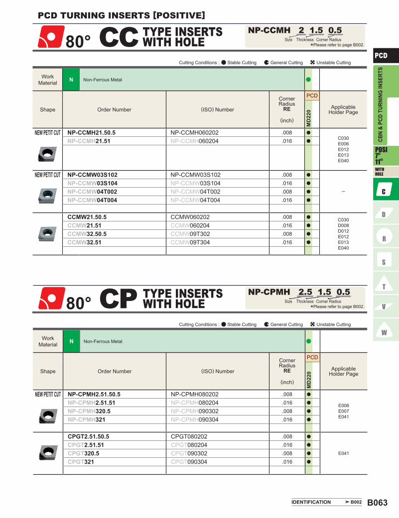
B063
PCD80°
NP-CCMH 2 1.5 0.5CC
80° CP NP-CPMH 2.5 1.5 0.5
B002
POSI 7º11º
N
PCD
MD
220
NP-CCMH21.50.5 NP-CCMH060202 .008 a
C030E006E012E013E040
NP-CCMH21.51 NP-CCMH060204 .016 a
NP-CCMW03S102 NP-CCMW03S102 .008 a
─NP-CCMW03S104 NP-CCMW03S104 .016 a
NP-CCMW04T002 NP-CCMW04T002 .008 a
NP-CCMW04T004 NP-CCMW04T004 .016 a
CCMW21.50.5 CCMW060202 .008 a C030D008D012E012E013E040
CCMW21.51 CCMW060204 .016 a
CCMW32.50.5 CCMW09T302 .008 a
CCMW32.51 CCMW09T304 .016 a
N
PCD
MD
220
NP-CPMH2.51.50.5 NP-CPMH080202 .008 a
E006E007E041
NP-CPMH2.51.51 NP-CPMH080204 .016 a
NP-CPMH320.5 NP-CPMH090302 .008 a
NP-CPMH321 NP-CPMH090304 .016 a
CPGT2.51.50.5 CPGT080202 .008 a
E041
CPGT2.51.51 CPGT080204 .016 a
CPGT320.5 CPGT090302 .008 a
CPGT321 CPGT090304 .016 a
CBN
& PC
D TU
RNIN
G IN
SERT
S
TYPE INSERTS WITH HOLE *Please refer to page B002.
Corner RadiusThicknessSize
Cutting Conditions : Stable Cutting General Cutting Unstable Cutting
Work Material
Shape
NEW PETIT CUT
NEW PETIT CUT
Order Number (ISO) Number
Corner Radius
RE
(inch)
Applicable Holder Page
Non-Ferrous Metal
TYPE INSERTS WITH HOLE Size Thickness Corner Radius
*Please refer to page B002.
Cutting Conditions : Stable Cutting General Cutting Unstable Cutting
Work Material Non-Ferrous Metal
Shape
NEW PETIT CUT
(ISO) Number
Corner Radius
RE
(inch)
Applicable Holder PageOrder Number
PCD TURNING INSERTS [POSITIVE]
IDENTIFICATION
WITH HOLE

B064
PCD
90° SP SPGX 3 2 1
55° DC NP-DCMT 2 1.5 0.5 RF
POSI 7º
11º
N
PCD
MD
220
NP-DCMT21.50.5RF NP-DCMT070202R-F .008 aC031C032D009D013D040E008E013E014E042E043
NP-DCMT21.50.5LF NP-DCMT070202L-F .008 a
NP-DCMT21.51RF NP-DCMT070204R-F .016 a
NP-DCMT21.51LF NP-DCMT070204L-F .016 a
NP-DCMT32.50.5RF NP-DCMT11T302R-F .008 a
NP-DCMT32.50.5LF NP-DCMT11T302L-F .008 a
NP-DCMT32.51RF NP-DCMT11T304R-F .016 a
NP-DCMT32.51LF NP-DCMT11T304L-F .016 a
DCMW21.50.5 DCMW070202 .008 sC031C032D009D013D040E008E013E014E042E043
DCMW21.51 DCMW070204 .016 a
DCMW32.50.5 DCMW11T302 .008 a
DCMW32.51 DCMW11T304 .016 a
N
PCD
MD
220
SPGX321 SPGX090304 .016 s
─
SPGX322 SPGX090308 .031 s
CBN
& PC
D TU
RNIN
G IN
SERT
SPCD TURNING INSERTS [POSITIVE]
a : Inventory maintained. s : Inventory maintained in Japan. <1 insert in one case>
TYPE INSERTS WITH HOLE Size Thickness Corner Radius
*Please refer to page B002.
Cutting Conditions : Stable Cutting General Cutting Unstable Cutting
Work Material
Shape
NEW PETIT CUT
(ISO) Number
Corner Radius
RE
(inch)
Applicable Holder PageOrder Number
Non-Ferrous Metal
TYPE INSERTS WITH HOLE Size Thickness Corner Radius
*Please refer to page B002.
Cutting Conditions : Stable Cutting General Cutting Unstable Cutting
Work Material
Shape (ISO) Number
Corner Radius
RE
(inch)
Applicable Holder PageOrder Number
Non-Ferrous Metal
WITH HOLE

B065
PCD
TCMW 2 1.5 0.5TC60°
B002
POSI 7º
N
PCD
MD
220
TCMW21.50.5 TCMW110202 .008 a
C035E015E016E044
TCMW21.51 TCMW110204 .016 s
TCGW1.210.5 TCGW060102 .008 s
─
TCGW1.211 TCGW060104 .016 s
TCGW1.212 TCGW060108 .031 s
CBN
& PC
D TU
RNIN
G IN
SERT
S
TYPE INSERTS WITH HOLE *Please refer to page B002.
Corner RadiusSize Thickness
Cutting Conditions : Stable Cutting General Cutting Unstable Cutting
Work Material
Shape Order Number (ISO) Number
Corner Radius
RE
(inch)
Applicable Holder Page
Non-Ferrous Metal
IDENTIFICATION
WITH HOLE

B066
PCD60° TP NP-TPMX 1.8 1.5 0.5 RF
POSI 11º
N
PCD
MD
220
NP-TPMX1.81.50.5RF NP-TPMX090202R-F .008 s
E007E045
NP-TPMX1.81.50.5LF NP-TPMX090202L-F .008 s
NP-TPMX1.81.51LF NP-TPMX090204L-F .016 s
NP-TPMX1.81.52LF NP-TPMX090208L-F .031 s
NP-TPMX220.5LF NP-TPMX110302L-F .008 s
NP-TPMX221LF NP-TPMX110304L-F .016 s
NP-TPMX222LF NP-TPMX110308L-F .031 s
NP-TPMX320.5LF NP-TPMX160302L-F .008 s
NP-TPMX321LF NP-TPMX160304L-F .016 s
NP-TPMX322LF NP-TPMX160308L-F .031 s
NP-TPMH1.51.50.5RF NP-TPMH080202R-F .008 a
E007E045
NP-TPMH1.51.50.5LF NP-TPMH080202L-F .008 a
NP-TPMH1.51.51RF NP-TPMH080204R-F .016 a
NP-TPMH1.51.51LF NP-TPMH080204L-F .016 a
NP-TPMH1.81.50.5RF NP-TPMH090202R-F .008 a
NP-TPMH1.81.50.5LF NP-TPMH090202L-F .008 a
NP-TPMH1.81.51RF NP-TPMH090204R-F .016 a
NP-TPMH1.81.51LF NP-TPMH090204L-F .016 a
NP-TPMH220.5RF NP-TPMH110302R-F .008 a
NP-TPMH220.5LF NP-TPMH110302L-F .008 a
NP-TPMH221RF NP-TPMH110304R-F .016 a
NP-TPMH221LF NP-TPMH110304L-F .016 a
NP-TPMH320.5RF NP-TPMH160302R-F .008 s
NP-TPMH320.5LF NP-TPMH160302L-F .008 s
NP-TPMH321RF NP-TPMH160304R-F .016 s
NP-TPMH321LF NP-TPMH160304L-F .016 s
TPGT320.5RF TPGT160302R-F .008 s
─
TPGT320.5LF TPGT160302L-F .008 s
TPGT321RF TPGT160304R-F .016 s
TPGT321LF TPGT160304L-F .016 s
CBN
& PC
D TU
RNIN
G IN
SERT
S
TYPE INSERTS WITH HOLE Size Thickness Corner Radius
*Please refer to page B002.
Cutting Conditions : Stable Cutting General Cutting Unstable Cutting
Work Material Non-Ferrous Metal
Shape
NEW PETIT CUT
NEW PETIT CUT
(ISO)Number
Corner Radius
RE
(inch)
Applicable Holder PageOrder Number
WITH HOLE
a : Inventory maintained. s : Inventory maintained in Japan. <1 insert in one case>
PCD TURNING INSERTS [POSITIVE]

B067
PCD
B002
POSI 11º
N
PCD
MD
220
TPGV1.81.50.5RF TPGV090202R-F .008 s
─
TPGV1.81.50.5LF TPGV090202L-F .008 s
TPGV1.81.51RF TPGV090204R-F .016 s
TPGV1.81.51LF TPGV090204L-F .016 s
TPGV220.5RF TPGV110302R-F .008 s
TPGV220.5LF TPGV110302L-F .008 s
TPGV221RF TPGV110304R-F .016 s
TPGV221LF TPGV110304L-F .016 s
TPGX1.51.50.5 TPGX080202 .008 s
E007E045
TPGX1.51.51 TPGX080204 .016 s
TPGX1.51.52 TPGX080208 .031 s
TPGX1.81.50.5 TPGX090202 .008 s
TPGX1.81.51 TPGX090204 .016 s
TPGX1.81.52 TPGX090208 .031 s
TPGX220.5 TPGX110302 .008 s
TPGX221 TPGX110304 .016 s
TPGX222 TPGX110308 .031 s
TPGX321 TPGX160304 .016 s
TPGX322 TPGX160308 .031 s
CBN
& PC
D TU
RNIN
G IN
SERT
S
Cutting Conditions : Stable Cutting General Cutting Unstable Cutting
Work Material
Shape (ISO) Number
Corner Radius
RE
(inch)
Applicable Holder PageOrder Number
Non-Ferrous Metal
IDENTIFICATION
WITH HOLE

B068
PCD
35° VC NP-VCGT 1.5 1.5 V5 RF
35° VB NP-VBGT 2 2 V5 RF
POSI 5º7º
N
PCD
MD
220
NP-VBGT22V5RF NP-VBGT1103V5R-F .002 s C028C029D010D011D014D015E009E010
NP-VBGT220.2RF NP-VBGT110301R-F .004 s
NP-VBGT220.5RF NP-VBGT110302R-F .008 s
NP-VBGT221RF NP-VBGT110304R-F .016 s
N
PCD
MD
220
NP-VCGT1.51.5V5RF NP-VCGT0802V5R-F .002 s
C036D048D049E009E010E016E017E046
NP-VCGT1.51.50.2RF NP-VCGT080201R-F .004 s
NP-VCGT1.51.50.5RF NP-VCGT080202R-F .008 s
NP-VCGT1.51.51RF NP-VCGT080204R-F .016 s
NP-VCGT22V5RF NP-VCGT1103V5R-F .002 s
NP-VCGT220.2RF NP-VCGT110301R-F .004 s
NP-VCGT220.5RF NP-VCGT110302R-F .008 s
NP-VCGT221RF NP-VCGT110304R-F .016 s
CBN
& PC
D TU
RNIN
G IN
SERT
S
s : Inventory maintained in Japan.<1 insert in one case>
TYPE INSERTS WITH HOLE Size Thickness Corner Radius
*Please refer to page B002.
Cutting Conditions : Stable Cutting General Cutting Unstable Cutting
Work Material
Shape Order Number (ISO) Number
Corner Radius
RE
(inch)
Applicable Holder Page
Non-Ferrous Metal
TYPE INSERTS WITH HOLE Size Thickness Corner Raduis
*Please refer to page B002.
Cutting Conditions : Stable Cutting General Cutting Unstable Cutting
Work Material
Shape (ISO) Number
Corner Radius
RE
(inch)
Applicable Holder PageOrder Number
Non-Ferrous Metal
PCD TURNING INSERTS [POSITIVE]
WITH HOLE
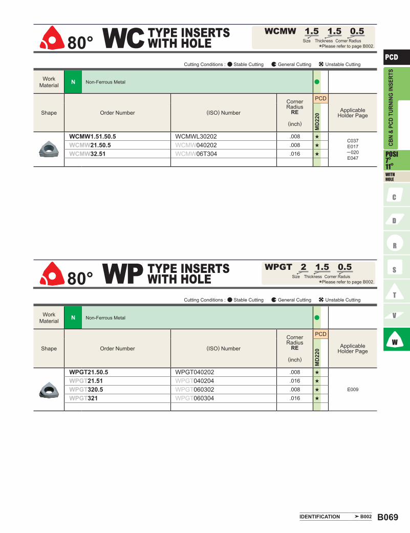
B069
PCD80°
WCMW 1.5 1.5 0.5WC
80° WP WPGT 2 1.5 0.5
B002
POSI 7º11º
N
PCD
MD
220
WCMW1.51.50.5 WCMWL30202 .008 sC037E017─020E047
WCMW21.50.5 WCMW040202 .008 s
WCMW32.51 WCMW06T304 .016 s
N
PCD
MD
220
WPGT21.50.5 WPGT040202 .008 s
E009
WPGT21.51 WPGT040204 .016 s
WPGT320.5 WPGT060302 .008 s
WPGT321 WPGT060304 .016 s
CBN
& PC
D TU
RNIN
G IN
SERT
S
TYPE INSERTS WITH HOLE Corner Radius
*Please refer to page B002.Size Thickness
Cutting Conditions : Stable Cutting General Cutting Unstable Cutting
Work Material
Shape (ISO) Number
Corner Radius
RE
(inch)
Applicable Holder PageOrder Number
Non-Ferrous Metal
TYPE INSERTS WITH HOLE Size Thickness Corner Raduis
*Please refer to page B002.
Cutting Conditions : Stable Cutting General Cutting Unstable Cutting
Work Material
Shape Order Number (ISO) Number
Corner Radius
RE
(inch)
Applicable Holder Page
Non-Ferrous Metal
IDENTIFICATION
WITH HOLE

B070
PCD
60° TE TEGX 3 2 0.5 R
55° DE DEGX 4 3 0.5 RF
POSI 20º
N
PCD
MD
220
DEGX430.5RF DEGX150402R-F .008 s
C041
DEGX430.5LF DEGX150402L-F .008 s
DEGX431RF DEGX150404R-F .016 s
DEGX431LF DEGX150404L-F .016 s
N
PCD
MD
220
TEGX320.5R TEGX160302R .008 s
C042E028
TEGX320.5L TEGX160302L .008 s
TEGX321R TEGX160304R .016 s
TEGX321L TEGX160304L .016 s
TEGX320.5 TEGX160302 .008 s
C042E028
TEGX321 TEGX160304 .016 s
CBN
& PC
D TU
RNIN
G IN
SERT
S
s : Inventory maintained in Japan.<1 insert in one case>
TYPE INSERTS WITH HOLE Size Thickness Corner Radius
*Please refer to page B002.
Cutting Conditions : Stable Cutting General Cutting Unstable Cutting
Work Material
Shape (ISO) Number
Corner Radius
RE
(inch)
Applicable Holder PageOrder Number
Non-Ferrous Metal
TYPE INSERTS WITH HOLE Size Thickness Corner Raduis
*Please refer to page B002.
Cutting Conditions : Stable Cutting General Cutting Unstable Cutting
Work Material
Shape (ISO) Number
Corner Radius
RE
(inch)
Applicable Holder PageOrder Number
Non-Ferrous Metal
PCD TURNING INSERTS [POSITIVE]
WITH HOLE

B071
PCD
VDGX 3 2 0.5 RFVD35°
B002
POSI 15º
N
PCD
MD
220
VDGX320.5RF VDGX160302R-F .008 s
C043
VDGX320.5LF VDGX160302L-F .008 s
VDGX321RF VDGX160304R-F .016 s
VDGX321LF VDGX160304L-F .016 s
CBN
& PC
D TU
RNIN
G IN
SERT
S
TYPE INSERTS WITH HOLE *Please refer to page B002.
Size Thickness Corner Radius
Cutting Conditions : Stable Cutting General Cutting Unstable Cutting
Work Material
Shape Order Number (ISO) Number
Corner Radius
RE
(inch)
Applicable Holder Page
Non-Ferrous Metal
IDENTIFICATION
WITH HOLE

B072
PCD
60° TP TPG 2 2 0.5
90° SP SPG 3 2 0.5
B002
POSI 11º
N
PCD
MD
220
SPG320.5 SPGN090302 .008 s
─
SPG321 SPGN090304 .016 s
SPG322 SPGN090308 .031 s
SPG421 SPGN120304 .016 s
SPG422 SPGN120308 .031 s
SPG423 SPGN120312 .047 s
N
PCD
MD
220
TPG220.5 TPGN110302 .008 s
─
TPG221 TPGN110304 .016 s
TPG222 TPGN110308 .031 s
TPG320.5 TPGN160302 .008 s
TPG321 TPGN160304 .016 s
TPG322 TPGN160308 .031 s
CBN
& PC
D TU
RNIN
G IN
SERT
S
TYPE INSERTS WITHOUT HOLE Size Thickness Corner Radius
*Please refer to page B002.
Cutting Conditions : Stable Cutting General Cutting Unstable Cutting
Work Material
Shape (ISO) Number
Corner Radius
RE
(inch)
Applicable Holder PageOrder Number
Non-Ferrous Metal
TYPE INSERTS WITHOUT HOLE Size Thickness Corner Raduis
*Please refer to page B002.
Cutting Conditions : Stable Cutting General Cutting Unstable Cutting
Work Material
Shape
Corner Radius
RE
(inch)
Applicable Holder Page(ISO) NumberOrder Number
Non-Ferrous Metal
IDENTIFICATION
PCD TURNING INSERTS [POSITIVE]
WITHOUT HOLE
s : Inventory maintained in Japan.<1 insert in one case>

B073
Memo


![Performance of Lasered PCD- and CVD-Diamond Cutting ......laser machining of PCD-cutting inserts does not reduce the tool life time [20]. On one hand it could be proven that any thermal](https://static.fdocuments.us/doc/165x107/600cf2173461d148ec64147c/performance-of-lasered-pcd-and-cvd-diamond-cutting-laser-machining-of-pcd-cutting.jpg)


