Guidance Systems: The Brains of Motion Control Systems Breivik.pdfPresentation Guidance Systems,...
40
Presentation Guidance Systems, Morten Breivik, March 2011 Guidance Systems: The Brains of Motion Control Systems Dr. Morten Breivik Centre for Ships and Ocean Structures Norwegian University of Science and Technology A Minuteman III missile is launched on a suborbital trajectory toward the Kwajalein Atoll from Vandenberg Air Force Base in California, USA on June 14, 2006. Courtesy of Goleta Air & Space Museum.
Transcript of Guidance Systems: The Brains of Motion Control Systems Breivik.pdfPresentation Guidance Systems,...

Presentation Guidance Systems, Morten Breivik, March 2011
Guidance Systems:The Brains of Motion Control Systems
Dr. Morten BreivikCentre for Ships and Ocean Structures
Norwegian University of Science and Technology
A Minuteman III missile is launched on asuborbital trajectory toward the KwajaleinAtoll from Vandenberg Air Force Base inCalifornia, USA on June 14, 2006.Courtesy of Goleta Air & Space Museum.

Motion Control Hierarchy: High Level Control Intermediate Level Control Low Level Control
Guidance: Definitions and History
Motion Control Basics: Operating Spaces Actuation Properties Motion Control Scenarios
Target Tracking: Line-Of-Sight Guidance Pure Pursuit Guidance Constant Bearing Guidance Relations to Nature and Robotics
Path Following: Straight Line Paths Circular Paths Regularly Parameterized Paths
Outline Guidance Systems, Morten Breivik, March 2011

Motion Control Example: Motion Control Design for Unmanned Surface Vehicles (USVs)
Future Challenges: Autonomy and Human-Like Cognitive Functionality
References: Literature on Guidance and Motion Control
Brave New World: Links to Videos and Reports on Norwegian USV Research
Outline Guidance Systems, Morten Breivik, March 2011

Motion Control Hierarchy A vehicle motion control system involves at least 3 levels
of control in a hierarchical structure:
Guidance Systems, Morten Breivik, March 2011

High Level Control A vehicle motion control system involves at least 3 levels
of control in a hierarchical structure:
High level control involves the calculation of motion reference signals which correspond to desired vehicle maneuvers
The main task of this control level is to solve motion control objectives associated with important motion control scenarios, including: Target tracking (tracking a moving target) Path following (traversing a geometric path) Formation control (cooperation between multiple vehicles) Collision avoidance (avoiding both static and dynamic objects)
Constituting the strategic level of control, it is essentially the brain of all the nested control loops that together make up a vehicle motion control system
Humans currently participate directly at this level most of the time
The autonomous part of the strategic level is called the guidance system
Guidance Systems, Morten Breivik, March 2011

Intermediate Level Control A vehicle motion control system involves at least 3 levels
of control in a hierarchical structure:
The intermediate control level considers how actual vehicle motion can be generated and calculates the forces and moments required to execute the desired maneuvers commanded by the high-level controllers
Controllers at this level are typically designed by model-based methods and must handle both parametric uncertainties and environmental disturbances
The commands issued by these controllers are supplied as reference signals to low-level actuator controllers by means of a distribution scheme known as control allocation
Humans often participate directly at this level of control
Guidance Systems, Morten Breivik, March 2011

Low Level Control A vehicle motion control system involves at least 3 levels
of control in a hierarchical structure:
Low level control is related to the local control of vessel actuators such as tunnel thrusters, azimuth thrusters, water jets, rudders, propellers, etc.
The controllers at this level ensure that the actuators in fact deliver the forces and moments requested by the intermediate control module and ultimately that the vehicle moves as requested by the guidance system
This control level is the tactical level with the greatest bandwidth demand
Humans usually do not participate directly at this level
Guidance Systems, Morten Breivik, March 2011

Guidance According to Shneydor , guidance is defined as:
“The process for guiding the path of an object towards a given point, which in general may be moving”
Charles Stark Draper, the father of inertial navigation, stated:“Guidance depends upon fundamental principles and involves devices that are similar for vehicles moving on land, on water, under water, in air, beyond the atmosphere within the gravitational field of earth and in space outside this field”
Shneydor, N. A. (1998). “Missile Guidance and Pursuit: Kinematics, Dynamics and Control”, Horwood Publishing, Ltd.
Guidance Systems, Morten Breivik, March 2011

Guidance Consequently, guidance represents a fundamental methodology
which transcends particular vehicle applications
Guidance is concerned with the transient motion behavior associated with achieving motion control objectives
The most rich and mature literature on guidance is typically found within the guided missile community
Locke defines a guided missile as:“A space-traversing unmanned vehicle which carries within itself the means for controlling its flight path”
Locke, A. S. (1955). “Guidance”, D. Van Nostrand Company, Inc.
Guidance Systems, Morten Breivik, March 2011

Guidance Guided missiles have been operational since World War II, so
organized research on guidance theory has been conducted almost as long as organized research on control theory
Continuous progress in missile hardware and software technology has made increasingly advanced guidance concepts feasible for implementation
Today, missile guidance theory encompass: Classical guidance laws Optimal guidance laws Guidance laws based on fuzzy logic and neural network theory Differential-geometric guidance laws Guidance laws based on differential game theory
Guidance Systems, Morten Breivik, March 2011

Fundamental motion control concepts include: Operating spaces Actuation properties Motion control scenarios
We mainly distinguish between two operating spaces: Work space: The physical space in which a vehicle moves Configuration space: Constituted by the set of variables sufficient
to specify all points of a rigid-body vehicle in the work space
Each of the variables associated with the configuration of a vehicle is called a degree of freedom (DOF)
2D3 DOFs
3D6 DOFs
Motion Control Basics Guidance Systems, Morten Breivik, March 2011

We mainly distinguish between two actuation properties: Full actuation: A fully actuated vehicle is able to independently
control all its DOFs simultaneously Underactuation: An underactuated vehicle is not able to
independently control all its DOFs simultaneously
A vehicle that is underactuated in its configuration space can still achieve meaningful tasks in its work space. It will however typically lack the ability to achieve arbitrary attitude assignments
At high speeds, most vehicles are underactuated in their configuration space anyway (e.g., aircraft, missiles, ships, underwater vehicles, etc.), forced to maneuver energy-efficiently:
Ships are typically underactuated above 1.5 – 2 m/s (3 – 4 knots)
Motion Control Basics Guidance Systems, Morten Breivik, March 2011

Motion Control Basics Motion control scenarios are traditionally divided into: Point stabilization: Motion toward a stationary point Trajectory tracking: Motion along a time-parameterized path Path following: Motion along a time-independent path Maneuvering: A mix between trajectory tracking and path following
where the time parameterization of the path can be changed dynamically, for example according to the vehicle dynamics
These scenarios are typically defined by motion control objectives which are given as configuration space tasks and are therefore best suited for fully actuated vehicles
They also typically involve desired motion which has been defined a priori (beforehand) in some sense and do not seem to consider the case where no future motion information is available
A new classification scheme is therefore suggested which considers both apriori and non-apriori scenarios and where the motion control objectives are given as work space tasks
Such scenarios cover more broadly and are also suited for underactuated vehicles
Guidance Systems, Morten Breivik, March 2011

Motion Control Scenarios Target tracking:
The control objective is to track the position of a target which moves such that only its instantaneous motion is known. When the target is stationary, this scenario corresponds to point stabilization
For this scenario, it is impossible to separate the spatio-temporal constraint associated with the target position (to be at a certain position at a certain time) into two separate – spatial and temporal – constraints
Path following: The control objective is to converge to and follow a predefined
geometric path, which only involves a spatial constraint No restrictions are placed on the temporal propagation along the path
Path tracking: The control objective is to track the position of a target which is
constrained to move along a predefined path, corresponding to the trajectory tracking scenario
For this scenario, it is possible to separate the spatio-temporal constraint of the target position into two separate constraints
By disregarding any a priori path information, this scenario can also be viewed as a target tracking scenario and handled with corresponding methods, although resulting in a strange tracking behavior relative to the path
Guidance Systems, Morten Breivik, March 2011

Motion Control Scenarios Path maneuvering:
The control objective is to employ knowledge about vehicle maneuverability constraints to feasibly negotiate (or somehow optimize the negotiation of) a predefined path, for instance by traversing the path as fast as possible without derailing at any point
Consequently, we either have:
Target tracking, where only instantaneous (and also historic) information about the target point is available:
Path scenarios, where the target point traverses a path that is apriori known:
Guidance Systems, Morten Breivik, March 2011

Target Tracking Concerning tracking of moving targets, the missile guidance
community probably has the most comprehensive experience: The object that is supposed to destroy another object is commonly
referred to as either a missile, an interceptor or a pursuer Conversely, the threatened object is typically called a target or an
evader
Here, the neutral designations interceptor and target will be used
An interceptor missile typically undergoes 3 operational phases:1. Launch (become airborne and acquire steering controllability)2. Midcourse (only coarse pursuit of the target position)3. Terminal (achieve accurate intercept of the target position)
In the following, we will consider 3 terminal guidance strategies: Line-of-sight (LOS) guidance Pure pursuit (PP) guidance Constant bearing (CB) guidance
Guidance Systems, Morten Breivik, March 2011

Target Tracking Line-of-sight (LOS) guidance:
3-point guidance scheme The interceptor must constrain its motion along the line of sight
between a specific reference point and the target Similar to pure pursuit guidance when on the LOS path Typically employed for surface-to-air missiles, often mechanized by
a ground station which illuminates the target with a beam that the guided missile is supposed to ride (beam-rider guidance)
Guidance Systems, Morten Breivik, March 2011

Target Tracking Pure pursuit (PP) guidance:
2-point guidance scheme The interceptor must align its linear velocity along the interceptor-
target line of sight This strategy is equivalent to a predator chasing a prey in the
animal world and very often results in a tail chase Typically employed for air-to-surface missiles
Guidance Systems, Morten Breivik, March 2011

Target Tracking Constant bearing (CB) guidance:
2-point guidance scheme The interceptor must align the relative interceptor-target velocity
along the interceptor-target line of sight Often referred to as parallell navigation (zero LOS rotation rate) Typically employed for air-to-air missiles Used for centuries by mariners to avoid collisions at sea Proportional navigation is the most common implementation method
(achieves target intercepts, matching only position)
Guidance Systems, Morten Breivik, March 2011

Target Tracking Constant bearing (CB) guidance:
Can also be implemented as a direct velocity assignment in order to achieve a target rendezvous (matching both position and speed)
Breivik, M. (2010). “Topics in Guided Motion Control of Marine Vehicles”, PhD Thesis, Norwegian University of Science and Technology, Trondheim, Norway.
Approachvelocity Resulting speed
profile along the x-axis
Guidance Systems, Morten Breivik, March 2011

Target Tracking The full picture:
In our consideration, guidance laws are thus equivalent with kinematic control laws, which can be given as either:
Speed and/or steering laws Direct velocity assignments
Guidance Systems, Morten Breivik, March 2011

Motion camouflage: Some predators are able to adjust their movement according to
their prey such that the prey perceive them as stationary objects in the environment
Such behavior is also reported for mating rituals and territorial disputes, for example involving dragonflies
Two types of motion camouflage are mainly employed in nature: Camouflage against an object close by (equivalent to LOS guidance) Camouflage against an object at infinity (equivalent to CB guidance)
The motion camouflage technique works since some creatures detect the motion component across the object-prey LOS far better than the component along the LOS
Guidance in Nature
Guidance Systems, Morten Breivik, March 2011

Robotic interception: Online optimization methods for time-optimal motion planning for
robot manipulators operating in dynamic environments are typically very computationally demanding
Computationally simple methods involving proportional navigation have been employed to achieve an intercept between a manipulator end effector (interceptor) and a moving object (target)
Guidance in Robotics
Piccardo, H. R. and G. Honderd (1991). “A New Approach to On-Line Path Planning and Generation for Robots in Non-Static Environments”, Robotics and Autonomous Systems, 8(3): 187–201.
Guidance Systems, Morten Breivik, March 2011
Path Following Assuming positive speed, path following basically amounts to
assigning suitable steering laws
Steering for straight lines: Enclosure-based steering Lookahead-based steering
Breivik, M. and T. I. Fossen (2009). “Guidance Laws for Autonomous Underwater Vehicles”, in A. V. Inzartsev (Ed.), Underwater Vehicles, pp. 51-76. IN-TECH Education and Publishing.
Cross-track error
Lookaheaddistance
Path-relative steering law
Enclosure circle
Guidance Systems, Morten Breivik, March 2011

Path Following Steering for circles: It is important to aim along the
path tangential and not along the path itself
NB: These two alternatives are identical for straight line paths, but not for curved paths
Guidance Systems, Morten Breivik, March 2011

Path Following Path following for regularly parameterized paths: Paths that never degenerate into a point nor have sharp corners In this case, a path-constrained collaborator is required to avoid the
kinematic singularity associated with the osculating circle
Related to the missile guidance laws, lookahead-based steering can be interpreted as pure pursuit of the lookahead point (“donkey and carrot” analogy)
Dynamic update law for the path-constrained collaborator:
Guidance Systems, Morten Breivik, March 2011

Path Following The lookahead-based steering law can also be written as:
The steering law is therefore equal to a saturated proportional control law. It is well known that a small lookahead distance Δ implies aggressive steering, which is intuitively confirmed by a correspondingly large proportional gain kp in the saturated control interpretation
Integral action can also be added into the steering law. Although not required in a purely kinematic setting, an integrator can be useful for vehicles which are under the influence of ocean currents without having access to velocity information:
However, care must be taken to avoid overshoot and windup effects when using integral action in the steering law
Guidance Systems, Morten Breivik, March 2011

Want to design a motion control system for an underactuated unmanned surface vehicle (USV) with an outboard engine:
Motion Control Example
Maritime Robotics’ Kaasbøll USV maneuvering in the Trondheimsfjord.
Guidance Systems, Morten Breivik, March 2011

For underactuated vehicles, the direction of the vehicle velocity is generally not equal to the vehicle heading
Therefore, it is important to control the vehice velocity and not the vehicle heading to achieve the desired motion control objectives
Velocity-based guidance laws have already been reviewed for target-tracking and path-following motion control scenarios. For underactuated vehicles, direct velocity assignments can be decomposed into speed and steering assignments
Motion Control Example
Heading angle
Course angle
Sideslip angle
Speed error
Steering error
Guidance Systems, Morten Breivik, March 2011
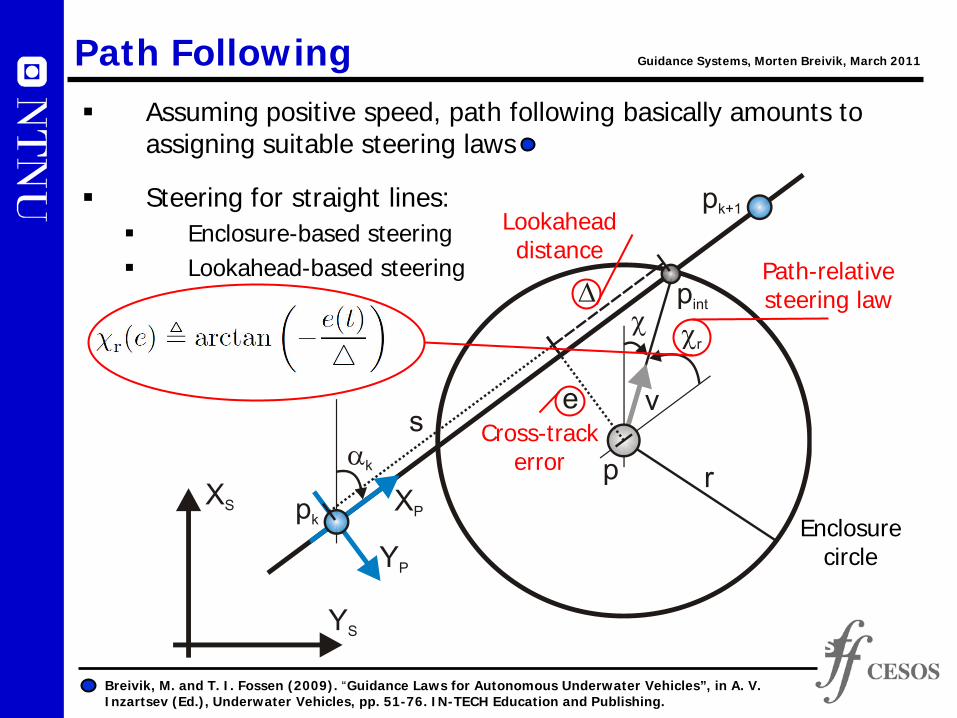
Motion control system in the hierarchical interpretation:
Motion Control Example
Strategic level:Desired motion -> Velocity commands
Tactical level:Velocity control -> Actuator commands
Execution level:Actuator control -> Actual motion
Guidance Systems, Morten Breivik, March 2011

Kaasbøll USV:
Modular design approach
Motion Control Example
Velocity controllers based on any favorite model-based
control method
Actuators which physically move the vehicle
OR
Guidance Systems, Morten Breivik, March 2011
Constant bearing guidance Lookahead-based
steering

Some plots showing the startup and steady state behavior of the Kaasbøll USV during a straight-line target tracking scenario :
In this full-scale experiment, a virtual target moves due north at a speed of 3 m/s (6 knots), while the USV is velocity-controlled using constant bearing guidance to achieve target rendezvous
Motion Control Example
Breivik, M., V. E. Hovstein and T. I. Fossen (2008). “Straight-Line Target Tracking for Unmanned Surface Vehicles”, Modeling, Identification and Control, 29(4):131-149.
Guidance Systems, Morten Breivik, March 2011

Current motion control systems make it possible for vehicles to achieve missions which humans carefully specify in advance, like a target-tracking motion control scenario. That is, the vehicles do what most machines can do better than people – provide very high precision in technical operations
However, it is not yet possible to give a vehicle’s control computer only approximate orders which it must boil down to something very concrete and practical itself
Such cognitive functions represent the next big step in the technology evolution for vehicle guidance systems
Future Challenges Guidance Systems, Morten Breivik, March 2011

In the long term it is desirable to develop more advanced cognitive guidance systems which will make the vehicles partly or completely independent of human intervention
Such autonomous vehicles will be able to make their own decisions in unfamiliar and unstructured environments. However, such abilities will require the boats to be equipped with intelligence similar to humans
It still remains to clarify whether we humans are so intelligent that we are able to understand our own intelligence and thus reproduce it artificially. If not, we will probably never witness truly autonomous vehicles, only bleak copies of our own capabilities
Future Challenges Guidance Systems, Morten Breivik, March 2011

A shift toward more autonomy will require a gradual introduction of increasingly advanced motion control functionality
In the short term, one of the most important functionalities is collision avoidance, which requires both sense and avoid abilities:
Sense: Access to both global (electronic charts, etc.) and local (radar, stereo vision, etc.) information about the surrounding environment
Avoid: Superior maneuverability through powerful actuators, as well as advanced motion control algorithms capable of performing both long-term (proactive) and short-term (reactive) planning to ensure avoidance
The main challenge in making practical use of a collision avoidance system lies in the sensor solutions. A composite sensor package which can be trusted to detect both large and small objects in all types of visibility and weather conditions must be developed
Future Challenges Guidance Systems, Morten Breivik, March 2011

We basically want to develop unmanned and autonomous vehicles like:
We are currently at the beginning of a technological development which will turn many things upside down. Incredible research challenges exist within the area of advanced guidance systems for unmanned and autonomous vehicles
Future Challenges Guidance Systems, Morten Breivik, March 2011

References Some relevant references on guidance systems and motion control:
Adler, F. P. (1956). “Missile Guidance by Three-Dimensional Proportional Navigation”, Journal of Applied Physics, 27(5): 500–507.
Battin, R. H. (1982). “Space Guidance Evolution - A Personal Narrative”, Journal of Guidance, Control, and Dynamics, 5(2): 97-110.
Bertram, V. (2008). “Cyber-Ships – Artificial Intelligence Technologies for Ships”, Copenhagen, Denmark, Skibsteknisk Selskab.
Breivik, M., V. E. Hovstein and T. I. Fossen (2008). “Straight-Line Target Tracking for Unmanned Surface Vehicles”, Modeling, Identification and Control, 29(4): 131-149.
Breivik, M. and T. I. Fossen (2009). “Guidance Laws for Autonomous Underwater Vehicles”, in A. V. Inzartsev (Ed.), Underwater Vehicles, pp. 51-76. IN-TECH Education and Publishing.
Breivik, M. (2010). “Topics in Guided Motion Control of Marine Vehicles”, PhD Thesis, Norwegian University of Science and Technology, Trondheim, Norway.
Cloutier, J. R., J. H. Evers and J. J. Feeley (1989). “Assessment of Air-to-Air Missile Guidance and Control Technology”, IEEE Control Systems Magazine, 9(6): 27–34.
Draper, C. S. (1971). “Guidance is Forever”, Navigation, 18(1): 26–50. Justh, E. W. and P. S. Krishnaprasad (2006). “Steering Laws for Motion Camouflage”,
Proceedings of the Royal Society A, 462(2076): 3629–3643. LaValle, S. M. (2006). “Planning Algorithms”, Cambridge University Press. Lin, C.-F. (1991). “Modern Navigation, Guidance, and Control Processing,
Volume II”, Prentice Hall, Inc.
Guidance Systems, Morten Breivik, March 2011

References Some relevant references on guidance systems and motion control:
Lin, C.-L. and Su, H.-W. (2000). “Intelligent Control Theory in Guidance and Control System Design: An Overview”, Proceedings of the National Science Council ROC, 24(1): 15-30.
Locke, A. S. (1955). “Guidance”, D. Van Nostrand Company, Inc. Loe, Ø. A. G. (2008). “Collision Avoidance for Unmanned Surface Vehicles”, MSc Thesis,
Norwegian University of Science and Technology, Trondheim, Norway. MacKenzie, D. A. (1990). “Inventing Accuracy: A Historical Sociology of Nuclear Missile
Guidance”, MIT Press. Mizutani, A., J. S. Chahl and M. V. Srinivasan (2003). “Motion Camouflage in Dragon-
flies”, Nature, 423: 604. Papoulias, F. A. (1991). “Bifurcation Analysis of Line Of Sight Vehicle Guidance Using
Sliding Modes”, International Journal of Bifurcation and Chaos, 1(4): 849—865. Pastrick, H. L., S. M. Seltzer and M. E. Warren (1981). “Guidance Laws for Short-Range
Tactical Missiles”, Journal of Guidance and Control, 4(2): 98–108. Piccardo, H. R. and G. Honderd (1991). “A New Approach to On-Line Path Planning and
Generation for Robots in Non-Static Environments”, Robotics and Autonomous Systems, 8(3): 187–201.
Shneydor, N. A. (1998). “Missile Guidance and Pursuit: Kinematics, Dynamics and Control”, Horwood Publishing, Ltd.
Singer, P. W. (2009). “Wired for War: The Robotics Revolution and Conflict in the 21st Century”, Penguin.
Guidance Systems, Morten Breivik, March 2011

References Some relevant references on guidance systems and motion control:
Siouris, G. M. (2004). “Missile Guidance and Control Systems”, Springer-Verlag New York, Inc.
Spearman, M. L. (1978). “Historical Development of Worldwide Guided Missiles”, in Proceedings of the AIAA 16th Aerospace Sciences Meeting, Huntsville, Alabama, USA.
Westrum, R. (1999). “Sidewinder: Creative Missile Development at China Lake”, Naval Institute Press.
White, B. A. and A. Tsourdos (2001). “Modern Missile Guidance Design: An Overview”, in Proceedings of the IFAC Automatic Control in Aerospace, Bologna, Italy.
Yanushevsky, R. (2008). “Modern Missile Guidance”, CRC Press. Zarchan, P. (2002). “Tactical and Strategic Missile Guidance”, American Institute of
Aeronautics and Astronautics, Inc. Zbikowski, R. (2004). “Sensor-Rich Feedback Control”, IEEE Instrumentation &
Measurement Magazine, 7(3): 19-26.
Guidance Systems, Morten Breivik, March 2011

Brave New World… As inspiration for a new breed of control engineers developing the
next generation of advanced cognitive guidance systems for use in unmanned and autonomous vehicles, the following media-related material may be useful:
NRK Schrødingers Katt feature on Pilotless Boats
Research magazine Gemini report on Autonomous Robots at Sea
YouTube video on USV Formation Control in the Trondheimsfjord
Guidance Systems, Morten Breivik, March 2011