
Guidance on the use of rockbolts to support roadways in ... · PDF fileHealth and Safety...
32
Health and Safety Executive Guidance on the use of rockbolts to support roadways in coal mines This guidance on the support of mine roadways in coal mines by rockbolts was prepared, in consultation with the Health and Safety Executive (HSE), by the Deep Coal Mines Industry Advisory Committee which was appointed by the Health and Safety Commission as part of its formal advisory structures. The guidance represents what is considered to be good practice by members of the Committee. It has been agreed by the Commission. Under current legislation rockbolts may only be used as the principal support of mine roadways in coal mines if HSE has granted exemption from the requirements of section 49(i) of the Mines and Quarries Act 1954 and regulations 13 and 14 of the Coal and Other Mines (Support) Regulations 1966. It will be a condition of any such exemption, to carry out the rockbolting operations in accordance with the guidance. This webonly version replaces the 1996 edition of this guidance. Introduction 1 This document provides guidance on the safe use of rockbolts to support roadways in coal mines. It is aimed at coal mine managers, supervisors and mine workers who have responsibility for rockbolt support operations. 2 The guidance applies to the places in coal mines where rockbolts provide the principal support and may include: ❋ development headings and junctions; ❋ coal face development drivages; ❋ retreat district gate roads including the face ‘Tee’ junction; ❋ room and pillar coal production districts; ❋ special purpose drivages, eg to house equipment. 3 Examples of places which may not be suitable are: ❋ goaf scours; ❋ gate roads serving advancing faces; ❋ cross measures drifts; ❋ headings formed by shotfiring off the solid. 4 Roadways immediately next to goafs are not suitable for support by rockbolts and are not covered by this guidance. 1 of 32 pages
Transcript of Guidance on the use of rockbolts to support roadways in ... · PDF fileHealth and Safety...

Health and Safety Executive
Guidance on the use of rockbolts to support roadways in coal mines
This guidance on the support of mine roadways in coal mines by rockbolts was prepared, in consultation with the Health and Safety Executive (HSE), by the Deep Coal Mines Industry Advisory Committee which was appointed by the Health and Safety Commission as part of its formal advisory structures. The guidance represents what is considered to be good practice by members of the Committee. It has been agreed by the Commission.
Under current legislation rockbolts may only be used as the principal support of mine roadways in coal mines if HSE has granted exemption from the requirements of section 49(i) of the Mines and Quarries Act 1954 and regulations 13 and 14 of the Coal and Other Mines (Support) Regulations 1966. It will be a condition of any such exemption, to carry out the rockbolting operations in accordance with the guidance.
This webonly version replaces the 1996 edition of this guidance.
Introduction
1 This document provides guidance on the safe use of rockbolts to support roadways in coal mines. It is aimed at coal mine managers, supervisors and mine workers who have responsibility for rockbolt support operations.
2 The guidance applies to the places in coal mines where rockbolts provide the principal support and may include:
❋ development headings and junctions; ❋ coal face development drivages; ❋ retreat district gate roads including the face ‘Tee’ junction; ❋ room and pillar coal production districts; ❋ special purpose drivages, eg to house equipment.
3 Examples of places which may not be suitable are:
❋ goaf scours; ❋ gate roads serving advancing faces; ❋ cross measures drifts; ❋ headings formed by shotfiring off the solid.
4 Roadways immediately next to goafs are not suitable for support by rockbolts and are not covered by this guidance.
1 of 32 pages

Health and Safety Executive
Definitions
5 The following definitions apply throughout this guidance:
❋ Freestanding supports are supports which are erected between the floor and roof, eg arches, girders, hydraulic powered supports, chocks/cribs, props and bars.
❋ Inspection officials are appointed to carry out inspections under regulation 12 of the Management and Administration of Safety and Health at Mines Regulations 1993 (MASHAM).
❋ Members of the management structure are the mine manager and other people appointed to the mine management structure under regulation 10 of MASHAM.
❋ Principal support is where rockbolts provide the support even where they are used in conjunction with supplementary support.
❋ Rockbolt is a bar inserted into the roof or side of a roadway which is used in conjunction with fully encapsulating resin or some other appropriate substance to provide reinforcement of the roof and sides of a roadway or working place in a mine.
❋ Rockbolted heading/roadway is a heading/roadway in which rockbolts provide the main means of support.
Geotechnical assessment and site investigation
6 A geotechnical assessment and site investigation are fundamental prerequisites for the design of a support system. The results need to be recorded.
7 The manager should appoint a suitably qualified and competent person to undertake and record the results of a geotechnical assessment and on the basis of the assessment design a safe and suitable rockbolt system. A suitable qualification for such a person would be a chartered engineer, or equivalent, who has had three years’ appropriate experience in work related to mine strata control. For the purposes of this booklet, this person is referred to as the design engineer.
8 The assessment needs to take into account all factors likely to affect the performance of the support system during the life of the roadway. It should also consider the strata deformation processes to be controlled and the action of the bolting system in controlling the deformation.
9 The area covered by the investigation needs to be defined and any subsequent support system design confined to that area (see paragraph 13). The assessment needs to incorporate all relevant features from the initial development and throughout its working life.
10 The site investigation needs to include reference to the following:
❋ geology: including the strata section, rock properties, faults, cleat, parting planes, presence of water or any substance likely to flow, borehole information and gradients. All factors need to be correlated relative to the mining horizon;
❋ stress: the direction and magnitude of the stress field components for premining, mining induced conditions and interaction;
❋ pillar design and effects: the assessment needs to include drawings and diagrams to illustrate potential risk areas;
❋ environmental effects: the effects of ambient temperature, mine water and associated impurities;
Guidance on the use of rockbolts to support roadways in coal mines 2 of 32 pages

Health and Safety Executive
❋ bond strength: measured by short encapsulation pull tests using the proposed rockbolting materials and components (see Appendix 1). The tests need to be carried out for all major roof horizon changes within the length of the proposed rockbolt and the effects of wet flushing or alternative dust control system on the bond strength determined. The bond strength needs to have a minimum value of 130 kNewtons, for a bond length of 0.3 m, over 50% of the bolt length;
❋ standup time: dilation related to distance from the face (see Appendix 9).
11 The assessment needs to be signed by the person or people carrying out the investigation.
12 If rockbolting is to be considered elsewhere in the same seam, sufficient investigation needs to be carried out to confirm that the conditions are similar to those at previous sites. If confirmed, the information established at those sites may be used again and reference made to the earlier site investigation.
13 A supplementary site investigation should be carried out whenever there is a major change in the method of work, lithology, structure or conditions.
Support system design
14 Where the site investigation and geotechnical assessment indicates that the strata is suitable for the use of rockbolts as the main means of support, a support design needs to be prepared. Where an existing design has already been proved, reference to it may be made for other roadways of similar dimensions in the same seam. This is providing that suitable and sufficient steps are taken to show that the geological conditions, rock properties and stress fields at both sites are substantially similar.
15 A design engineer will prepare the initial design of the rockbolting system on the basis of the results of the site investigation. As a minimum, the design needs to take account of the following:
❋ the profile of the heading; ❋ the length of rockbolts to be used in the roof and ribs. (The recommended
minimum length in the roof is 1.8 m); ❋ the density of rockbolts in the roof. (The recommended minimum density of
support is 1 bolt/sq m but site investigation may indicate a need for higher densities);
❋ the placing of rockbolts. It is recommended that bolts to be used in the roof are installed as close to the face of the heading as possible and as soon as practicable after exposure of the roof;
❋ the type of rockbolt. All bolts to be used in the roof should be fullcolumn resin bonded;
❋ holes drilled for roof holes. They need to be formed in such a way that the bond strength parameters are achieved and the finished hole diameter does not exceed the nominal bolt diameter by more than 7 mm;
❋ a system of support for the roadway sides, where the initial assessment demands the provision of such support.
16 When the initial design has been completed, documentation needs to be prepared detailing the:
❋ use of the roadway/junction; ❋ freestanding supplementary support if applicable; ❋ layout and dimensions of the rockbolting pattern;
Guidance on the use of rockbolts to support roadways in coal mines 3 of 32 pages

Health and Safety Executive
❋ specification of rockbolting consumables to be used; ❋ method of work; ❋ maximum face to bolt distance; and ❋ design verification monitoring system.
17 The design document should be signed by the design engineer and will form the basis of the manager’s support rules.
Design verification monitoring
18 The initial design of the support system needs to be verified by comprehensive monitoring.
19 Comprehensive monitoring for design verification involves detailed measurement of roof dilation and rockbolt loads. It may also involve detailed measurement of rib dilation and roadway internal measurements. Measurement of roof dilation needs to be to an accuracy of 1 mm at a minimum of 15 points over a height of at least 7 m. Rockbolt loads need to be measured on a minimum of four rockbolts distributed across the roadway section. Details of the instruments used are in Appendix 2 and 3.
20 Where changes are proposed in roadway dimensions or methods of working, or where they are observed to occur in geotechnical conditions, further design verification monitoring needs to be carried out to assess the continued validity of the design.
21 A plan needs to be prepared showing details of the siting of monitoring stations in relation to geological and mining features and include details of the instrumentation at each station. Each monitoring station needs to be given a unique identification code which can be used to identify readings.
22 Monitoring instruments need to be read by suitably trained, competent and authorised workers using appropriate equipment.
23 The monitoring results and interpretation need to be retained for future reference.
24 The results of the monitoring need to be interpreted by the design engineer. Any actions or changes recommended need to be included in the design documentation, and if appropriate, in the support rules.
Routine monitoring and recording scheme
25 Where rockbolts are used to support mine roadways, the manager needs to prepare a ‘Scheme for the routine monitoring of roadways’.
26 The manager needs to appoint a suitably qualified and competent person to implement, audit and coordinate the scheme. A suitable qualification would be a Higher National Certificate in a miningrelated subject together with at least six months’ relevant experience of strata control activities in a coal mine and the completion of a training course in rockbolting. For the purposes of this guidance this person is referred to as the rockbolting coordinator (coordinator). Where appropriate, sufficient suitably trained and competent people need to be appointed to assist in the performance of these duties.
27 The manager’s scheme needs to specify the:
Guidance on the use of rockbolts to support roadways in coal mines 4 of 32 pages

Health and Safety Executive
❋ procedures for the auditing of routine monitoring devices in rockbolted roadways;
❋ equipment to be used; ❋ duties of individuals and the required plans, schedules and reports.
28 The scheme needs to recognise the:
❋ need to monitor and report physical changes affecting the security of the support system;
❋ need to take remedial measures; ❋ maximum levels of movement allowed on the monitoring devices before action
is required; ❋ actions to be taken and the person responsible for taking the action.
Routine monitoring devices
29 Two main types of monitoring device are utilised for the routine monitoring of rockbolted roadways. These are dual height telltales and multihorizon extensometers.
Dual height telltales
30 Dual height telltales give visual indication of roof dilation. The construction, installation procedure and method of reading dual height telltales is shown in Appendix 4. The telltales need to be installed:
❋ to at least twice the height of the bolt length or 4.8 m, whichever is the greater; ❋ at intervals of not greater than 20 m maximum distance; ❋ at every junction; ❋ at areas of known or suspected instability; ❋ at areas of likely interaction from old and present workings, and enlarged
excavations.
31 Telltales can also be set at increased frequencies by people working on site or through supervisory or managerial instruction.
32 Telltales need to be installed as near vertical as possible drilled close to the centre of the roadway, and as close to the face of the heading as practicable, or as directed by the coordinator.
33 At the site of every telltale a high visibility sign needs to be placed bearing a unique reference code to enable the telltale to be easily identified for reporting and recording purposes.
34 All telltales which become defective, obscured or out of range need to be replaced as quickly as possible at the same height in the same hole or, when this is not possible, drill a new hole in close proximity. Specific duties under action levels may also be required. When someone replaces a telltale, the reading of the old telltale needs to be recorded and reported in writing that it has been replaced. This information is then given to both the command supervisor for the area and the coordinator. All replacement telltales need to be to a unique colour scheme.
35 Telltales need to be read by suitably trained and competent people by:
❋ observing the coloured bands; or ❋ measuring the graduation lines; or by ❋ electronic systems to a manned control point.
Guidance on the use of rockbolts to support roadways in coal mines 5 of 32 pages

Health and Safety Executive
36 The senior official’s attention needs to be drawn to any telltale movement in excess of 25 mm on either the A or B indicator or at the manager’s rules action level, whichever is the lower figure. Manager’s rules should also detail actions on the rates of movement appropriate for the specific mine site.
37 For recording purposes any telltale reading needs to be related to the unique reference code in paragraph 33.
Multihorizon extensometers
38 Multihorizon extensometers are monitoring devices designed to be installed by a suitably trained and competent person and provide detailed information on roof dilation to a minimum distance of 7.0 m above roof height.
39 There are two main types of extensometer:
❋ sonic extensometer; ❋ multiwire extensometer.
40 The construction and installation of the sonic extensometer is shown in Appendix 3 and that of the multiwire extensometer in Appendix 5.
41 Install multihorizon extensometers for routine monitoring at maximum intervals of 200 m in any direction or at closer frequency where conditions demand.
42 Install multihorizon extensometers for routine roof monitoring in vertical holes, drilled close to the centre of the roadway and as close to the face of the heading as practicable, unless directed differently by the coordinator.
43 At the site of every multihorizon extensometer, place a sign bearing a unique reference code to enable it to be easily identified for reporting and recording purposes.
44 Multihorizon extensometers need to be read by suitably trained, competent and authorised people using the appropriate equipment. For recording purposes, any reading needs to be related to the unique reference code. The information may be electronically transmitted to a control point.
45 Replace all routine monitoring multihorizon extensometers which become defective, obscured or out of range as quickly as possible. Where any multihorizon extensometer is replaced, amend the sign to indicate such replacement. The command supervisor for the area and the coordinator need to be notified in writing of any replacements.
Plans and schedules
Plan of rockbolted roadways
46 A plan needs to be prepared and maintained to indicate the parts of the mine where rockbolts are used as the main means of support. Post the plan where it can be easily seen by all those who have responsibilities under the manager’s scheme before they go underground. Make sure it is reviewed weekly.
Schedule of measurement zones and measurement frequency
47 A schedule needs to be maintained at the mine, listing all rockbolted roadways and the required frequency of measurement of monitoring devices in those
Guidance on the use of rockbolts to support roadways in coal mines 6 of 32 pages

Health and Safety Executive
roadways. An example is shown in Appendix 6. The recommended frequency of measurements is as follows:
❋ dualheight telltales which are installed in roadways within ‘Inbye districts’ need to be observed and reported on each shift by the inspection official and measured and recorded at least weekly;
❋ all routine monitoring devices installed in sections of roadways which are areas of known or suspected instability need to be measured and recorded at least daily;
❋ measure and record all other routine monitoring devices at the mine at least once each month;
❋ where any adverse reading or trend is recorded, measurement and recording need to be carried out for each shift.
48 Divide every rockbolted area of the mine into measurement zones to enable the systematic measurement, recording and auditing of routine monitoring devices at the prescribed frequency.
Inspecting officials’ telltale checklists
49 Produce a telltale checklist for every district containing rockbolted roadways and update it at least weekly to take account of new and replacement telltales. An example checklist is shown in Appendix 7.
Duties of people in relation to the mine monitoring scheme
Mine manager
50 The mine manager ensures that a monitoring scheme is in place to maintain stability of mine roadways supported by rockbolts. The manager appoints a coordinator to manage and coordinate the scheme.
51 In the absence of the coordinator, the manager can appoint a similarly trained and competent person to act as a substitute.
52 The manager appoints sufficient suitably trained and competent people and grants facility to ensure compliance with the scheme.
53 The manager sets the level of movement at which action is to be taken and specifies the remedial measures to be taken at those levels.
Mine rockbolt coordinator
54 The coordinator ensures that the manager’s scheme for routine monitoring of rockbolted roadways is fully implemented and keeps the manager informed, so that the scheme is regularly updated.
55 The coordinator ensures that command supervisors and inspection officials have the requisite information to enable them to fulfil their duties in relation to support of mine roadways.
56 The coordinator has the following specific duties:
❋ to ensure that routine monitoring devices are installed or replaced to the standard and frequency specified;
❋ to ensure that the schedule of measurement zones and measuring frequency is maintained;
Guidance on the use of rockbolts to support roadways in coal mines 7 of 32 pages

Health and Safety Executive
❋ to ensure that all relevant workers are informed of the current action levels and that the appropriate remedial actions are being taken;
❋ to report to the manager the results of remedial actions and continued requirements until a position of stability is recorded;
❋ to ensure that all routine monitoring devices at the mine are measured and recorded at the frequency specified in the scheme;
❋ to ensure that the manager or their nominated representative is informed of any abnormal results on a daily basis;
❋ to collate and assess all information on defects and abnormalities affecting the stability of rockbolted roadways. The coordinator needs to confer with appropriate members of the management structure and advise them of the required remedial action;
❋ to ensure that records of all measurements of routine monitoring devices and copies of their reports to the manager are maintained at the mine for at least three years;
❋ to ensure that any reported geotechnical features or changes which may affect stability are brought to the attention of the appropriate members in the management structure.
Inspection officials
57 Where an inspection district includes areas of rockbolted roadway, an inspection official should visually examine every dual height telltale in the roadway and record any defects and abnormalities in the statutory report.
58 The inspection official needs to ensure:
❋ they are familiar with the presence of any rockbolted roadways within that district;
❋ they have the appropriate telltale checklists for that district; ❋ they are familiar with the action levels; and ❋ during their inspection, they:
read every telltale by observing the coloured bands and record on the checklist the condition of every telltale which has registered change;
examine the condition of every telltale and examine whether they are properly identified;
ensure telltales are installed at the appropriate frequency and replaced when necessary;
examine the condition of the support system; examine for any geotechnical change or features; take action on any adverse aspect found.
59 If the inspection official believes any defect or abnormality affecting the stability of a rockbolted roadway needs more attention, they should inform relevant people as soon as possible. Such people are the appropriate command supervisors and the senior members of the management structure on duty at the mine.
60 At the end of the inspection official’s shift, the following information should be included in the inspection report:
❋ defects or abnormalities affecting the stability of the rockbolted roadways; ❋ defects in the monitoring system; ❋ telltales replaced during the shift; ❋ remedial work carried out; ❋ remedial work required; ❋ geotechnical change; and ❋ those who have been informed of these matters.
Guidance on the use of rockbolts to support roadways in coal mines 8 of 32 pages

Health and Safety Executive
61 At the end of the shift they should submit their completed inspection report and telltale checklist as designated by the manager.
Surveyor
62 The surveyor should ensure that the plan of rockbolted roadways is maintained, reviewed and updated. They have to inform the manager and the coordinator of any predicted geotechnical changes which may affect the stability of rockbolted roadways.
Operators
63 Operators should install rockbolts:
❋ to the manager’s support rules; ❋ to the manager’s Code of Practice; ❋ to the instruction of a coordinator or official; ❋ according to the manufacturer’s/supplier’s instructions.
Training
64 All workers involved with rockbolting need to receive suitable training (see Appendix 8). Records of such training are issued to the workers involved on successful completion of the training. Additional training needs to be provided where circumstances change and for refresher purposes.
Consumable items
65 All consumable items forming part of the roadway support system specified in paragraphs 1416 must be suitable for the purpose when installed in compliance with instructions provided by the supplier. A product would be regarded as suitable if:
❋ it had received an acceptance number under the British Coal Corporation’s procedures for the Acceptance of Strata Reinforcement Materials and Equipment between 1 April 1992 and 30 June 1995; or
❋ it can be shown, by means of independently conducted and assessed type testing, to meet the criteria set out in the draft British Standard for Strata reinforcement support system components used in coal mines; or
❋ where no criteria as referred to above exist, that: a laboratory test programme is set out to simulate, as closely as is
practicable, operational conditions; tests to this programme are conducted by an independent accredited test
house and a report is prepared; the results of the test are assessed independently and found to be
satisfactory; an assessment of any risk to safety and/or health has been carried out; the supplier of the product is in possession of a letter, from the assessing
body, setting out the conditions under which the product may be used underground. Field trials may be required to validate performance.
Guidance on the use of rockbolts to support roadways in coal mines 9 of 32 pages

Health and Safety Executive
Appendix 1 Underground determination of bond strength Steel rockbolt/resin system Short encapsulation pull test
Introduction
The short encapsulation pull test is used to measure the performance of a rockbolt/resin/rock system. The test is performed underground and is the ultimate proof test of a bolt/resin/rock system. It should replicate the procedures, consumables and equipment in use for the support.
Brief description
A series of holes are drilled to varying depths and bolts of the required length are installed with a short resin capsule to give an encapsulated bolt length of not more than 300 mm. The pull test needs to be performed after a curing period of at least 1 hour and not more than 24 hours. After this time an axial load is applied to the end of the bolt and the bolt extension measured. The load is applied up to 220 kN or until the maximum load of the system has been achieved, whichever is the greater.
Procedure
Equipment
❋ Borehole micrometer. ❋ Cable tie wraps for preparation of short resin capsules. ❋ Knife. ❋ Tape measure. ❋ Pulltest equipment comprising:
a suitable hydraulic ram; pressure gauge capable of reading pressures equivalent to a load of 300 kN
to an accuracy of better than 10 kN; dial gauge capable of reading to 0.01 mm; monopod to support dial gauge; bearing plate; drawbar; shims of varying thickness.
Note: The ram and pressure gauge need to be calibrated regularly (at a minimum of three monthly intervals) to produce a plot of pressure versus force applied.
Number of tests
A minimum of two tests need to be carried out at each of the chosen roof horizons. As an example, for a 2.4 m bolt, these horizons would normally be at 600, 1200, 1800 and 2300 mm. If significant changes in geology occur within the bolted horizon, further tests need to be carried out at other horizons to determine their influence, if any, on the bond strength of any proposed bolting system.
Bolt preparation
The bolt length needs to be at least 40 mm longer than the hole length to allow full engagement of the drawbar on the threaded end of the bolt. All test bolts, including full length bolts, need to be cut square to the bolt axis.
Guidance on the use of rockbolts to support roadways in coal mines 10 of 32 pages

Health and Safety Executive
Location
Place pull test bolts as close as practicable to the face of the heading. Choose a section of reasonably flat roof which is not subject to spalling. The test bolts should not be installed through mesh or straps and need to be at least 300 mm apart. Bolts of the same length need to be separated by at least 1 m.
Capsule preparation and measurement of embedment length
Method using reamed out hole
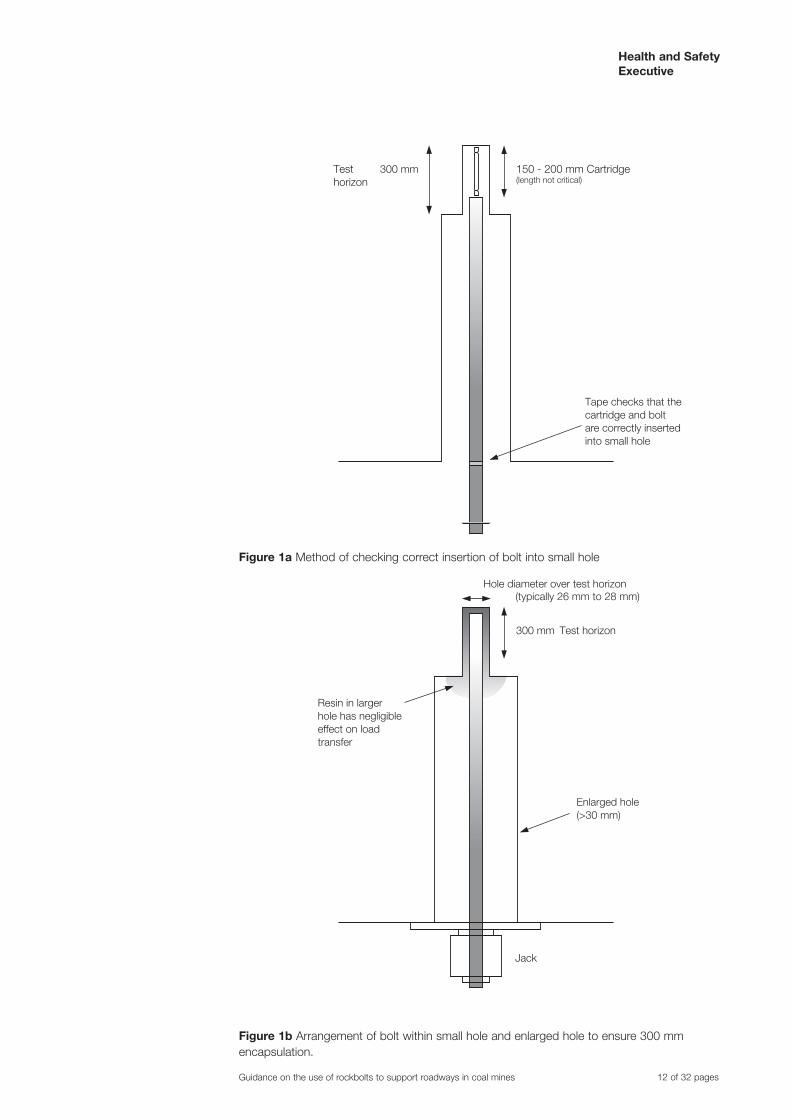
The rockbolt hole needs to be drilled to the top of the test horizon using the required bit and then reamed out to a larger diameter to within 300 mm of the hole depth. This procedure will ensure accurate knowledge of the encapsulation length (Figures 1a and 1b).
When testing a 22 mm bolt in a nominal 27 mm diameter hole, an embedment length of 300 mm is usually achieved with a cartridge length of 170 mm.
Prepare the 170 mm long test resin capsules from the fast setting resin found in the heading using the tie wraps and removing the excess capsule. Insert the bolt and resin cartridge by hand to ensure the resin cartridge is not torn on the lip between the larger and smaller holes. Place a locating mark on the bolt corresponding to the correct insertion depth of bolt and cartridge to ensure correct insertion into the smaller hole (Figure 1a).
Method using nonreamed hole
There may be occasions when the method set out in the last three paragraphs is not appropriate for the site. This is particularly true when drilling weak mudstones and flushing with water. In this case quantities of the mixture of mudstone and water can be forced by the reamer bit into the 300 mm long test section contaminating the surface of the test borehole. This coating may then reduce the mechanical lock between resin and rock leading to spurious pull test results. In these circumstances replace the reamed out hole method by the following:
❋ Drill hole to length using standard bit. ❋ Measure: borehole diameter; bolt diameter; resin capsule diameter. ❋ Determine the resin capsule length to produce not more than 300 mm bolt
encapsulation using the formula:
Capsule length = (Hole D2 Bolt D2 ) x encapsulated length Capsule D2
❋ Prepare test resin capsules of the calculated length from the resin used in the heading using the tie wraps and removing the excess capsule.
Hole preparation
The same drilling machine and operator need to be used throughout the tests. Use the drill bit specified for the site for drilling the test holes.
❋ Use a new bit. ❋ Measure the bit diameter before each test. ❋ Use wet drilling unless clearly stipulated otherwise. ❋ Drill holes to the required depth. ❋ Using a borehole micrometer, determine the mean diameter over the top
300 mm of the hole by taking several readings in this region.
Guidance on the use of rockbolts to support roadways in coal mines 11 of 32 pages
Health and Safety Executive
150 - 200 mm Cartridge (length not critical)
300 mmTesthorizon
Tape checks that the cartridge and boltare correctly inserted into small hole
300 mm Test horizon
Hole diameter over test horizon (typically 26 mm to 28 mm)
Jack
Enlarged hole(>30 mm)
Resin in largerhole has negligibleeffect on loadtransfer
Figure 1a Method of checking correct insertion of bolt into small hole
Figure 1b Arrangement of bolt within small hole and enlarged hole to ensure 300 mm encapsulation.
Guidance on the use of rockbolts to support roadways in coal mines 12 of 32 pages

Health and Safety Executive
Bolt installation
The surface condition of the test section of bolt needs to be free from rust, grease, paint, dirt or any other surface contaminant.
❋ Insert the capsule and bolt and push the capsule to the back of the test hole by hand.
❋ Raise the machine to the bolt and engage. ❋ Thrust and spin the bolt slowly to the back of the hole taking three to five
seconds, after which the bolt should be spun for at least a further five seconds. ❋ Wait for a suitable period, 30 seconds for fast set resin for example, and then
lower the machine. ❋ Identify the test bolt for length, by marking the roof and/or making a site plan.
Pull testing
Bolts need to be pulled no sooner than one hour and no later than 24 hours after installation. This is to ensure that the resin has time to cure and that no timedependent roof movement mechanically locks the bolt in the hole.
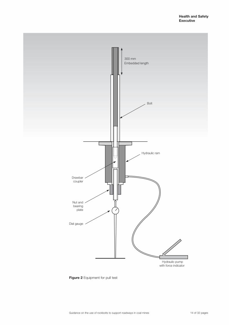
Assemble the equipment as shown in Figure 2. Align the ram along the axis of the bolt and make sure the bolt is not in contact with the wall of the hole. This is best achieved by first trimming any loose material from around the mouth of the hole and then aligning the assembly by wedging steel shims between the roof and bearing plate. When the assembly is fully aligned, the stem of the dial gauge is located into the ident on the end of the pull bar so that it is also in line with the bolt axis.
At least two skilled operators are required to operate the pump and to read the dial gauge.
Apply the bolt load slowly and smoothly and without pause. The bolt displacement needs to be noted at 10 kN intervals.
Guidance on the use of rockbolts to support roadways in coal mines 13 of 32 pages
Health and Safety Executive
Embedded length300 mm
Bolt
Hydraulic ram
Dial gauge
Nut andbearing
plate
Hydraulic pumpwith force indicator
Drawbarcoupler
Figure 2 Equipment for pull test
Guidance on the use of rockbolts to support roadways in coal mines 14 of 32 pages
Health and Safety Executive
Analysis
Computer software is available to calculate the yield bond stress of the rock/resin/bolt system.
The software is based on the following calculations:
EExtension in bolt = F x LF
S x π x D2
4
Bond displacement = Measured bolt displacement – (bolt extension + drawbar extension)
Where:
F = Applied force (Newtons) LF = Bolt free length (mm) = bolt length – (encapsulated length + length
in pull bar) Es = Young’s modulus for steel (206 000 MPa) Bolt D = Nominal bolt diameter (mm)
A graph of applied force (kN) v bond displacement (mm) needs to be plotted. The bond strength is the applied force at which the slope of the graph falls below 20 kN/mm. Where the bond length is not 300 mm, the results need to be corrected to a 300 mm bond using the formula:
Corrected bond strength (kN) = measured bond strength (kN) x 300 encapsulation length (mm
The reported results need to include the average measured test hole diameter and the encapsulation length. A suggested format for a pull test log sheet is shown in Figure 3.
Test requirements
In general, the average bond strength over 50% of the hole length needs to exceed 130 kN for a bond length of 300 mm. This value is equivalent to a bond stress of 5 MPa for a test hole diameter of 27.6 mm.
Guidance on the use of rockbolts to support roadways in coal mines 15 of 32 pages

Health and Safety Executive
PU
LL T
ES
T R
ES
ULT
S
CO
LLIE
RY:
D
ISTR
ICT:
D
ATE
:
MM
: B
IT T
YP
E :
BIT
Ø:
EN
CA
PS
ULA
TIO
N L
EN
GTH
: TE
ST
HO
RIZ
ON
:
BO
LT
LEN
GTH
mm
BO
LT
RIB
Ø
mm
BO
LT
CO
RE
Ø
mm
HO
LE
mm
RE
SIN
CA
PS
ULE
Ø m
m
RE
SIN
LEN
GTH
mm
BO
LT
FRE
E
LEN
GTH
mm
kN
1 2
3 4
5 6
7 8
9 10
11
12
1
0 2
10
3
20
4
30
5
40
6
50
7
60
8
70
9
80
10
90
11
100
12
110
INS
TALL
TIM
E
RE
MA
RK
S
120
130
140
150
PU
LL T
IME
160
170
180
190
200
210
220
Figure 3 An example of a pull test log sheet
Guidance on the use of rockbolts to support roadways in coal mines 16 of 32 pages

Health and Safety Executive
Appendix 2 Strain gauged rockbolts
Description
Strain gauged rockbolts are used to measure axial and bending strains imposed on the rockbolts when installed in a roadway. The strain gauged bolts replace some or all of the normal bolts in the bolting pattern.
Strains are measured using pairs of strain gauges attached to opposite sides of the rockbolts at intervals along its length. From the measured strains, the bolt mean strains and strain differences can be computed at the strain gauge position and bolt load profiles and bending moments estimated.
The bolts must be correctly installed and aligned to give representative results.
Specification
The strain gauged bolts need to be manufactured from actual rockbolts as used in the support system, ie:
❋ same steel; ❋ same surface profile; ❋ same length, diameters, thread etc.
Install the strain gauges diametrically opposed in aligned pairs at intervals along the axis of the bolts.
Make sure the maximum distance of the first pair from each end of the bolt does not exceed 0.2 m. Make sure the maximum axial distance apart of gauge pairs does not exceed 0.3 m.
The minimum number of gauge pairs for various bolt lengths are therefore:
❋ 1.8 m bolts 6 pairs; ❋ 2.1 m bolts 7 pairs; ❋ 2.4 m bolts 8 pairs; ❋ 2.7 m bolts 9 pairs.
For bolt lengths greater than 2.7 m, the distance between gauge pairs may be increased beyond 0.3 m, providing a minimum of nine gauge pairs are installed.
The strain gauged bolts have to be capable of being installed in an identical manner to that used for normal bolts. Make sure they are provided with a suitable connector to allow reading of the gauges before and after installation, using suitable monitoring equipment. The bolts need to be subjected to testing and quality control procedures during and after manufacture.
Installation
Install the strain gauged bolts as part of the normal cycle of bolting operations using the same equipment, consumables and bolting patterns as for normal bolt installation. Read the bolts shortly before installation and again as soon as possible after installation. During installation align the bolts so that the strain gauge pairs are aligned across the roadway or mine opening (ie the bolt axial plane containing the strain gauge pairs is perpendicular to the roadway or mine opening axis).
This is necessary to obtain measurement of the strain difference at the gauge pairs due to lateral shear in the roadway roof.
Guidance on the use of rockbolts to support roadways in coal mines 17 of 32 pages

Health and Safety Executive
Reading and results analysis
Use suitable I.S. instrumentation, cables and connectors to take readings of the analysis strain gauges at the specified intervals. Analyse the results using suitable computer software, in terms of mean strains and strain differences, load profiles and bending moments.
Guidance on the use of rockbolts to support roadways in coal mines 18 of 32 pages

Health and Safety Executive
Appendix 3 Sonic extensometer
Introduction
The sonic probe extensometer is designed to measure the distance between pairs of magnets up to 10 m apart to an accuracy of 0.02 mm.
The instrument consists of a flexible probe with a transducer head attached and a portable battery powered readout unit. The probe is inserted into a predrilled hole, usually of 43 mm diameter, containing up to 20 permanent magnets which are anchored to the strata. This measurement system is known as the sonic extensometer (see Figure 4).
Installation procedure
A vertical hole, at least 7 m long, is drilled into the centre of the roof at the face of the heading. A flexible, plastic, hollow tube is then inserted in the hole and anchored in place. Up to 20 permanent magnets are then, in turn, placed around this central guide tube and anchored at predetermined intervals along the hole.
Readings are taken by inserting the flexible probe in the central guide tube and connecting the probe transducer to the readout box. All magnet distances are referred to the magnet located at the collar of the borehole and the magnet locations are measured in sequence.
Principle of operation
When connected to the readout unit, the probe receives a small current pulse which travels along a thin walled metal tube within the probe. At each magnet position the interaction of the static field (due to the magnet) and the field (due to the current pulse) produces a torsional deformation in the thin walled tube. This deformation is transmitted down the tube as a ‘sonic’ pulse and detected by a torsional transducer located at the end of the probe. Sonic pulses from each magnet position arrive at the transducer head at different times, depending on how far they have travelled. The speed of the mechanically transmitted, sonic, pulse is known and, using a very accurate timer, the readout unit calculates and displays the positions of the magnets with high resolution.
Results
Sonic extensometer software is available which can be used to analyse and present the data in a variety of ways, including:
❋ total roof movement at the anchor positions at different times or face advance; ❋ strain between anchors at different times or face advance; ❋ total movement at individual anchor positions plotted against time or face
advance.
Guidance on the use of rockbolts to support roadways in coal mines 19 of 32 pages

Health and Safety Executive
Guide tube anchoredat top of hole
Typically43 mm
MagnetAnchor
Up to 20 magnetsanchored to strata
Reference magnetand anchor
Sonic extensometer probeinserted in the guide tube
To readout
At least 7 metres
Figure 4 Sonic extensometer
Guidance on the use of rockbolts to support roadways in coal mines 20 of 32 pages

Health and Safety Executive
Appendix 4 Dual height telltale
Introduction
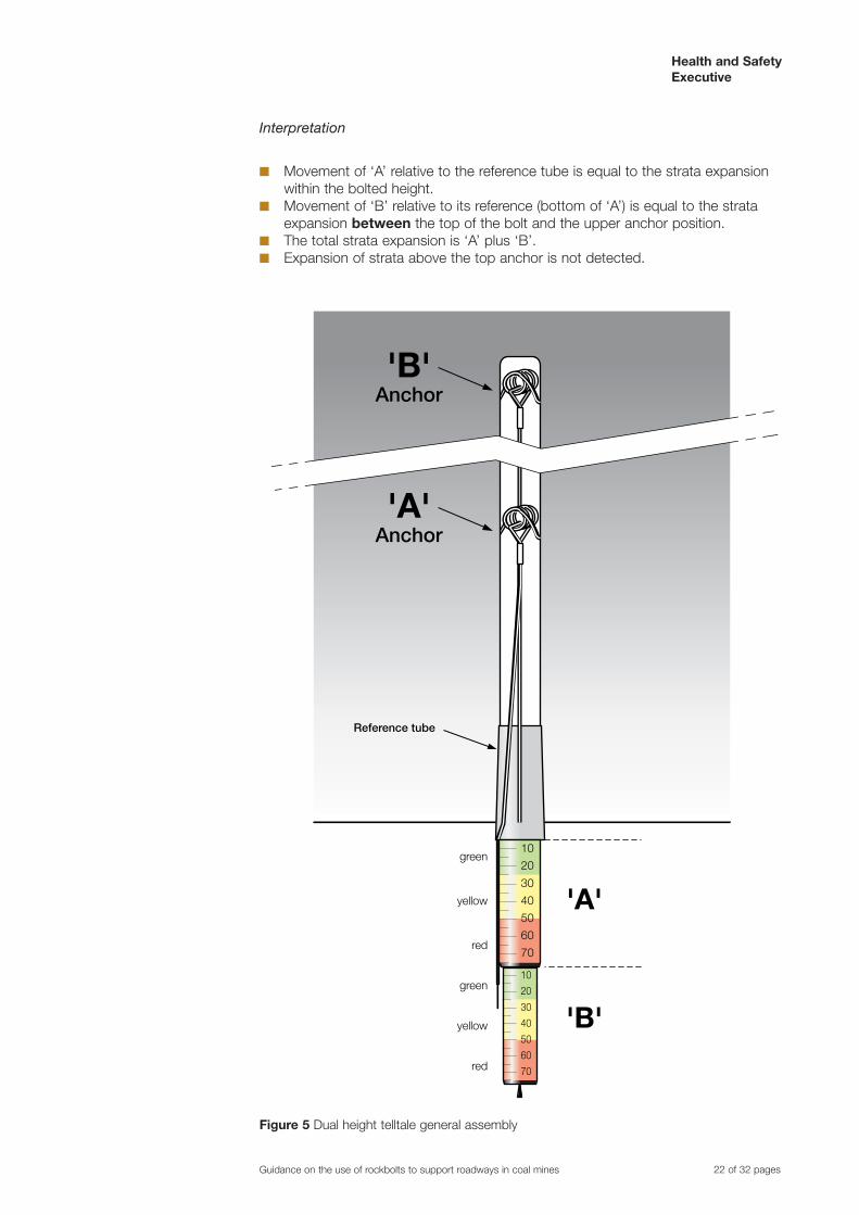
Dual height telltales are available for use in a variety of hole sizes from nominal 27 mm diameter to nominal 55 mm diameter. The general assembly is shown in Figure 5.
Installation
❋ Drill hole, using appropriate bit size, to the required height (2 x bolt height or 4.8 m, whichever is greater).
❋ Insert reference tube and push in tight. ❋ Insert top anchor, attached to smallest indicator ‘B’, to top of hole. Check for
firm anchorage. ❋ Insert lower anchor, attached to Iarger indicator ‘A’, to 0.3 m below the bolted
height, eg 2.1 m for 2.4 m bolt. ❋ Position the top of the green band on indicator ‘A’ to be level with bottom of
reference tube. Align to scale. Crimp ferrule in position. ❋ Position the top of the green band on indicator ‘B’ to be level with bottom of
indicator ‘A’. Align to scale. Crimp ferrule in position. ❋ Record details: position of hole, date and time, anchor heights.
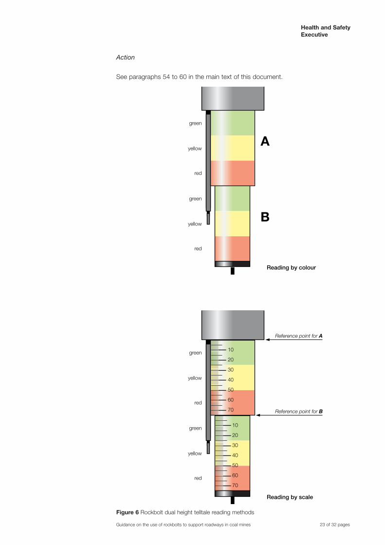
Reading methods (see Figure 6)
1. By colour
Report whole and part bands visible, for example:
‘A’: 1/2 green, yellow, red.
‘B’: 3/4 yellow, red.
2. By scale
Report measurement, in millimetres, lining up with reference mark for each anchor.
Reference for ‘A’ is bottom of reference tube.
Reference for ‘B’ is bottom of indicator ‘A’.
Scale has millimetre divisions, with centimetre marks. For example:
‘A’: 12 mm;
‘B’: 31 mm.
Guidance on the use of rockbolts to support roadways in coal mines 21 of 32 pages
Health and Safety Executive
Interpretation
❋ Movement of ‘A’ relative to the reference tube is equal to the strata expansion within the bolted height.
❋ Movement of ‘B’ relative to its reference (bottom of ‘A’) is equal to the strata expansion between the top of the bolt and the upper anchor position.
❋ The total strata expansion is ‘A’ plus ‘B’. ❋ Expansion of strata above the top anchor is not detected.
'A' Anchor
'B' Anchor
'A'
'B'
10
20
30
40
50
60
70
10
20
30
40
50
60
70
yellow
yellow
Reference tube
green
red
green
red
Figure 5 Dual height telltale general assembly
Guidance on the use of rockbolts to support roadways in coal mines 22 of 32 pages
Health and Safety Executive
Action
See paragraphs 54 to 60 in the main text of this document.
A
B
yellow
yellow
green
red
green
red
Reading by colour
Reading by scale
yellow
yellow
10
20
30
40
50
60
70
10
20
30
40
50
60
70
Reference point for A
Reference point for B
green
red
green
red
Figure 6 Rockbolt dual height telltale reading methods
Guidance on the use of rockbolts to support roadways in coal mines 23 of 32 pages
Health and Safety Executive
Appendix 5 Multiwire extensometers
Introduction
The multiwire extensometer consists of a 7 m long, vertical hole, usually of 35 mm diameter, drilled into the centre of the roof at the face of the heading, containing four separate wires, each anchored at a different height. The wires are terminated just below the bottom of the hole. The system can be read manually by measuring the distance from a reference point on each wire to the mouth of the hole. Alternatively, a remote monitoring system with suitable transducers and data transmission can be employed.
Principle of operation
A diagram of the system is shown in Figure 7. The wires are anchored at different heights in the borehole using two simple prong springs. These are cheap, effective and easily installed. The recommended anchorage heights of the springs are as follows:
❋ Minimum 7 m: The higher the top spring is anchored the more likely it is to be anchored in stable ground. This is desirable as the top anchor provides the reference against which the movement of all the others is compared.
❋ Bolt length +0.3 m: This anchor measures roof dilation just above the bolted height.
❋ Bolt length 0.3 m: This anchor is placed at the boundary between the bolted height and the roof above the bolted height. It is placed below the top of the bolts as it is possible for the tops of the bolts to be withdrawn from the overlying strata if roof dilation occurs within the top 0.3 m of the bolted height.
❋ 0.5 m: This anchor is placed between the immediate or lower roof, which can be prone to spall, flaking and slabbing, and the rest of the bolted height which needs to be fully stabilised by the rockbolts.
❋ Additional anchors may be placed at other heights if required. This would be appropriate if, for instance, there was an abrupt change of rock type within the length of the hole. The use of more than six anchors is not recommended as there is a danger of tangling the wires.
❋ The position of each anchor needs to be accurately recorded.
The wires are brought through a suitable reference point placed at the mouth of the hole and are terminated about 250 mm below the reference with an electrical connector. The wires have to be uniquely labelled. Numbered collars are usually used for this purpose.
Reading method
Place responsibility for reading the wire extensometers with a competent person, as it requires care, accuracy and consistency. That person also needs to be made responsible for recording the readings, analysing the data and providing the results to the manager of the mine, or a representative.
Clearly number each extensometer and keep a record of its position and number.
To read an extensometer, hang a weight (such as a safety lamp) from each wire in turn and measure the distance between the reference point and the upper end of the electrical connector. A steel tape, or ruler, is adequate for taking the readings which need to be recorded to the nearest millimetre. Ensure every effort is made for the same person to take the readings using the same tape to reduce errors. Record both the date and face distance for each set of readings.
Guidance on the use of rockbolts to support roadways in coal mines 24 of 32 pages

Health and Safety Executive
Results
The results may be graphed by hand. However, suitable software packages are available which can be used to analyse and present the data in a variety of ways including:
❋ total roof movement at the anchor positions at different times or face advance; ❋ strain between anchors at different times or face advance; ❋ total movement at individual anchor positions plotted against time or face
advance.
1 3 24
1
2
3
4Stable reference anchor
7 metres
Figure 7 Multiwire extensometer
Guidance on the use of rockbolts to support roadways in coal mines 25 of 32 pages

Health and Safety Executive
Appendix 6 Example of schedule of measurement zones and measurement frequencies
Location Zone number Measurement frequency
Telltales Extensometers
West Parkgate A & B roads to No.5 slit 1 W M
West Parkgate A & B roads No.5 to No.12 slit 2 W M
West Parkgate A & B roads No.12 to No.15 slit 3 W M
West Parkgate Intake C road Q to DT3 4 W M
West Parkgate Intake E road U to SA4 5 M M
103’s Access A & B roads & DM Return 6 M M
101’s Tail Gate C & D roads to No.6 slit 7 M M
101’s Tail Gate C & D No.6 to No.10 slit 8 W M
101’s Tail Gate C & D No.10 to No.14 slit 9 M M
101’s Tail Gate C & D No.14 to No.18 slit 10 M M
101’s Tail Gate C & D No.18 to No.22 slit 11 W M
101’s Tail Gate C & D No.19 to No.23 slit 12 W M
* W = Weekly M = Monthly
Guidance on the use of rockbolts to support roadways in coal mines 26 of 32 pages

Health and Safety Executive
Appendix 7 Inspecting official’s telltale checklist
COLLIERY:……………………………………....... SHIFT:……………………......... DATE:………………........
INSPECTION DISTRICT:..……………………………………...... NO. TELLTALES ON DISTRICT:………………...................
TELLTALE NUMBER ‘A’ COLOUR ‘B’ COLOUR SIGN Y/N ACTION/COMMENT
1
2
3
4
5
6
7
8
9
10
11
12
13
14
15
16
17
18
19
PRINT NAME:……………………………………… SIGNATURE:….....................................
All defects indicated on this form shall be extracted and recorded on your District Inspection Report.
This form shall be submitted to the Regulation 13.1(d) Office with your District Inspection Report.
Guidance on the use of rockbolts to support roadways in coal mines 27 of 32 pages

Health and Safety Executive
Appendix 8 Training
Training courses for those involved in rockbolting need to include the following aspects:
Managers
❋ Provide an understanding of the forces present in the rock and the redistribution of these as a consequence of mining operations.
❋ Illustrate the differences between conventional support and rockbolting. ❋ Explain the action of rockbolts in limiting roof movement and roadway
deformation. ❋ Highlight the adverse effects of poor installation standards. ❋ Provide an appreciation of monitoring techniques and the information obtained,
together with details of the installation and inspection procedures for the telltale monitoring system and also the setting of action levels and associated actions.
❋ Give guidance on the construction and implementation of the manager’s scheme for the routine monitoring of rockbolted roadways.
❋ Instruct on the inspection of bolted roof and ribs for signs of excessive bolt loading or deterioration, and the action to be taken if these are discovered.
Rockbolting coordinator
❋ An introduction to rock mechanics principles as applied to rockbolting including such topics as stress, the strata, design of reinforcement systems, underground engineering, consumables and several detailed case histories and include site visits where possible.
❋ Management of the manager’s scheme for the routine monitoring of rockbolted roadways.
❋ Installation, replacement and reading of all routine monitoring devices used at their mine.
❋ Familiarisation and use of the appropriate computer software. ❋ Setting of appropriate routine monitoring action levels for each area of the
mine. ❋ Setting of appropriate corresponding remedial action for action levels for each
area of the mine. ❋ Determination of appropriate measuring frequencies for routine monitoring
devices within the mine. ❋ Followup on remedial actions to secure stability. ❋ Formulation and updating of the schedule of measurement zones and
measuring frequency and related measuring timetables. ❋ Production of officials’ telltale checklists.
Officials
❋ An appreciation of basic rock mechanics as applied in rockbolting. ❋ All aspects of the mine monitoring system. ❋ Action levels. ❋ Action, duties and responsibilities. ❋ Remedial measures. ❋ Followup actions. ❋ Communication links. ❋ All aspects of the telltale checklist system at their mine. ❋ Appreciation of telltales. ❋ The correct installation of telltales. ❋ The replacement of telltales. ❋ The identification of telltales. ❋ Reading of telltales and appropriate action levels and the associated action to
be taken.
Guidance on the use of rockbolts to support roadways in coal mines 28 of 32 pages

Health and Safety Executive
❋ Instruction on the inspection of bolted roof and ribs for signs of excessive bolt loading or deterioration and the actions to be taken if these are discovered.
❋ Appropriate types of extra support to secure the roof in adverse conditions.
Operators
❋ The action of rockbolts and typical rockbolt patterns, highlighting the importance of good installation practice.
❋ Correct installation of rockbolts including adequate, practical onsite training. ❋ The sequence of operations and the time at which rockbolting is carried out. ❋ Maintenance of the rockbolting equipment (drilling machines etc) to ensure that
performance is maintained at designed levels. Particular attention needs to be directed to ensure provision of a sufficient supply of either hydraulic fluid, or compressed air, (as appropriate) to allow the drilling equipment to operate within design parameters.
❋ Provision of the correct length of drillrod in an undamaged condition and arrangements to ensure that the correct depth of hole is drilled (for example premarking the drill rod).
❋ The type, number of capsules and sequence of insertion of resin into the hole, together with the importance of the recommended mix and wait times.
❋ An appreciation of the manager’s scheme for rockbolt monitoring, the information indicated by means of the telltale monitoring system and action, where appropriate.
❋ An instruction that operators, in the event of difficulty in the application of rockbolting and monitoring, need to bring those matters to the attention of those having statutory responsibility for the supervision of operations.
❋ Where cablebolts are to be installed as additional support, operatives should also receive training in: correct cablebolt installation procedures including onsite training; approved consumables; personal protective equipment.
Guidance on the use of rockbolts to support roadways in coal mines 29 of 32 pages

Health and Safety Executive
Appendix 9 ‘Stand up time’ for extended cutouts: Assessing extended cutout distance
Where a distance greater than that required to set the next rockbolt support is cut, the possible effect of this extended cutout on roof stability needs to be assessed. This investigation ought to take the form of a progressive increase in cutout distance to the planned value with assessment at each stage as follows:
❋ Assess existing geotechnical information to confirm site suitability for an extended cut trial in terms of strata conditions, total roof movement, rate of movement and position of roof strain zones.
❋ Excavate the proposed increased cutout distance at the trial site without exposing the driver to unsupported roof.
❋ Do not install rockbolts. ❋ Install sufficient temporary standing support to allow a remotereading roof
extensometer to be installed halfway along the excavated section. ❋ Remove the temporary support if appropriate. ❋ Monitor roof dilation via the remotereading extensometer for the maximum
likely delay time before bolts are installed (48 hours is considered to be a minimum).
❋ The measured pattern of roof deformation should be comparable to previous site results. If there is no significant roof deformation in this period, an extended trial should take place as follows:
(a) assess the overall effect of the cutout distance on roadway stability by monitoring, eg installation of additional telltales and extensometers. The assessment needs to include the possibility of a fall over riding supported roof;
(b) if the results of the assessment are satisfactory, then, in stages, increase the cutout distance to the proposed value. Each stage needs to be subject to the monitoring and assessment described in (a).
The extended cutout distance needs to be considered a maximum and varied to suit the prevailing geotechnical conditions.
Guidance on the use of rockbolts to support roadways in coal mines 30 of 32 pages

Health and Safety Executive
Appendix 10 Lifting and suspension of equipment in rockbolted roadways
1 Rockbolts installed for roof support purposes should only be used (with suitable lifting shackles) for lifting or suspending light loads of up to a maximum of 1 tonne on an individual bolt, provided that the load on any row of bolts does not exceed 1 tonne in total.
2 Any bolt used for the lifting or suspension of equipment other than as above should be an anchor bolt.
3 Anchor bolts and their associated lifting shackles should be suitable for the purpose when installed in compliance with instructions provided by the supplier. They should be readily identifiable as anchor bolts both before and after installation.
4 The manager of the mine should make rules which cover the lifting or suspension of equipment in roadways supported by rockbolts and which take into account:
❋ the specification of the bolts and lifting shackles; ❋ the weight of the equipment; ❋ any induced load that may act on the bolts or suspension equipment. (The
dynamic load from the inflexion point of a tensioned conveyor is one example of an induced load);
❋ the number and layout of the bolts to ensure stability of the equipment; ❋ the manufacturer’s instructions for the installation and use of the bolts; ❋ the integrity of the bolt and the effects of corrosion; ❋ the additional imposed loading on the strata; and ❋ the need for additional roof support.
5 Before anchor bolts are installed the coordinator or a competent person appointed by the manager should examine and test, if necessary, the roof strata where the bolts are to be installed to ensure that the current support is adequate and the strata is in a suitable condition. This inspection should include inspection of nearby monitoring devices.
6 Following the installation of the anchor bolts and prior to subsequent use thereof, the coordinator or a competent person appointed by the manager should examine the installation of the anchor bolts, supplemented by tests if necessary, to confirm that they have been installed in accordance with the manager’s rules and the roof support has not deteriorated since the previous examination.
7 Where anchor bolts are installed for the purposes of lifting or suspension of equipment, monitoring of the strata should be incorporated in the manager’s rules. Where existing monitoring devices are remote from the site and would not be representative of the immediate area where the lifting operations are to take place, dedicated monitoring should be installed prior to lifting. Monitoring devices should be read before and after all lifting operations and should be monitored at regular intervals when lifting is taking place.
Guidance on the use of rockbolts to support roadways in coal mines 31 of 32 pages

Health and Safety Executive
Further information
HSE priced and free publications are available by mail order from HSE Books, PO Box 1999, Sudbury, Suffolk CO10 2WA Tel: 01787 881165 Fax: 01787 313995Website: www.hsebooks.co.uk (HSE priced publications are also available frombookshops and free leaflets can be downloaded from HSE’s website:www.hse.gov.uk.)
For information about health and safety ring HSE’s Infoline Tel: 0845 345 0055 Fax: 0845 408 9566 Textphone: 0845 408 9577 email: [email protected] orwrite to HSE Information Services, Caerphilly Business Park, Caerphilly CF83 3GG.
This document is available web only at: www.hse.gov.uk/pubns/mines01.pdf
© Crown copyright This publication may be freely reproduced, except foradvertising, endorsement or commercial purposes. First published 3/96. Pleaseacknowledge the source as HSE.
Published by the Health and Safety Executive Mines01 05/07 32 of 32 pages