Guidance notes for internal fixing above and below …...3.3 Floor/wall above ground applications It...
8
Guidance notes for internal fixing above and below ground Cavity Drainage Membrane incorporating Aquadrain THE ULTIMATE WATERPROOF MEMBRANE SYSTEM
Transcript of Guidance notes for internal fixing above and below …...3.3 Floor/wall above ground applications It...

Guidance notes for internal fixing above and below ground
Cavity Drainage Membrane incorporating Aquadrain
THE ULTIMATE WATERPROOF MEMBRANE SYSTEM
Before installing an Oldroyd membrane system an evaluation of the expected performance requirement is necessary. BS 8102 defines performance levels for the dryness of buildings and divides them into four grades. You must be satisfied that your proposed installation design will meet the expected requirement. When membranes are used internally in an existing structure certain basic design features have to be considered and acted upon. Listed below are some key points;-
Decide which wall finish system you intend to use as this will affect your fixing centres. Either a timber batten and plaster board, a galvanised dry lining system, or dot and dab may be used in front of the membrane.
Assess the possibility, however remote, of water entering the drainage cavity behind the membrane. Design in a facility for it to be channelled away either to an adequate gravity discharge drain or a sump with an automatically activated mechanical pump. (see section 3)
Assess the stability and suitability of the substrate to receive the membrane system and its fixings.
Within the area to be lined always incorporate adequate ventilation, preferably mechanically assisted into your installation design. We suggest that you refer to the CIRIA documents C139 and C140, Water Resisting Basements. Table 2.2 provides guidance on environmental requirements subject to the intended use of the basement.
Remove any organic material e.g. wall paper and consider the need to apply Safeguard Probor DB to the substrate before fitting the membrane.
In below ground level situations always remove any window/door frames, staircases etc before installation to ensure continuity of the membrane behind these fixtures (see section b)
Be aware that Oldroyd membranes and sealants are not designed to support a 'head' of water. It must be understood that they are designed to control the movement of water and vapour within the limitations of their capacities.
Before the installation commences attend to any structural repairs or other works likely to puncture or affect the membrane system.
Care must be taken not to puncture the floor membrane when flooring material is laid on top of the membrane.
FIXING OLDROYD MEMBRANE USING OLDROYD BRICK PLUGS
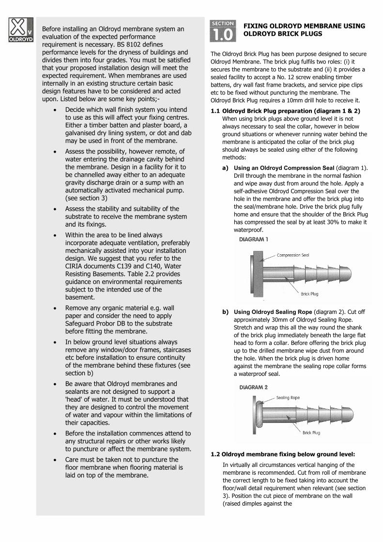
The Oldroyd Brick Plug has been purpose designed to secure Oldroyd Membrane. The brick plug fulfils two roles: (i) it secures the membrane to the substrate and (ii) it provides a sealed facility to accept a No. 12 screw enabling timber battens, dry wall fast frame brackets, and service pipe clips etc to be fixed without puncturing the membrane. The Oldroyd Brick Plug requires a 10mm drill hole to receive it.
1.1 Oldroyd Brick Plug preparation (diagram 1 & 2) When using brick plugs above ground level it is not always necessary to seal the collar, however in below ground situations or whenever running water behind the membrane is anticipated the collar of the brick plug should always be sealed using either of the following methods: a) Using an Oldroyd Compression Seal (diagram 1).
Drill through the membrane in the normal fashion and wipe away dust from around the hole. Apply a self-adhesive Oldroyd Compression Seal over the hole in the membrane and offer the brick plug into the seal/membrane hole. Drive the brick plug fully home and ensure that the shoulder of the Brick Plug has compressed the seal by at least 30% to make it waterproof.
b) Using Oldroyd Sealing Rope (diagram 2). Cut off
approximately 30mm of Oldroyd Sealing Rope. Stretch and wrap this all the way round the shank of the brick plug immediately beneath the large flat head to form a collar. Before offering the brick plug up to the drilled membrane wipe dust from around the hole. When the brick plug is driven home against the membrane the sealing rope collar forms a waterproof seal.
1.2 Oldroyd membrane fixing below ground level: In virtually all circumstances vertical hanging of the membrane is recommended. Cut from roll of membrane the correct length to be fixed taking into account the floor/wall detail requirement when relevant (see section 3). Position the cut piece of membrane on the wall (raised dimples against the

wall) at the selected starting point, ideally working from left to right. As an aid, temporarily secure near the top centre to create a 'pivot' point for alignment. Using a spirit level and/or a plumb line vertically align the membrane. At this stage establish the fixing requirements and centres for the intended wall finish as this will probably require specific brick plug positioning. Bearing in mind the fixing centre requirements drill two 10mm holes, to a minimum depth of 80mm, through the membrane into the substrate as near to the top of the membrane as possible. Offer prepared Oldroyd Brick Plugs into the holes and using a club/lump hammer gently tap home hitting true and square without excess force to prevent damaging the brick plug. This will allow the membrane to hang.
Continue to install prepared brick plugs in a similar fashion working evenly across and down the membrane at centres dictated by the intended wall finish requirements.
1.3 Oldroyd membrane fixing above ground level: The hanging of the actual membrane should follow the same procedure for 'below ground fitting' as outlined in section 1.2 above. Unless running water is anticipated behind the membrane it is not normally necessary to seal the collar of the brick plug when used above ground level. Your attention is drawn to the floor/wall junction details in section 3.0.
BRANE SEAMS (JOINS)
A fundamental requirement when using any membrane system is the ability to join one piece of membrane to another and form an effective seam. Dependent upon which type of membrane is being used there are various methods available. Most Oldroyd Membranes have a simple flange facility along one edge for this purpose.
2.1 Flange seam (see diagram 3) Along one edge of most Oldroyd Membranes is a flat flange and the other has a smooth strip between the first and second row of studs. Wipe clean the smooth strip between the first and second row of studs for the entire length of the intended seam. Apply Oldroyd Double Sided Tape to the smooth strip leaving the backing paper on at this stage. Align the flat flange of the next length of membrane over the previously applied double sided tape. When satisfied that the intended seam is straight and even, wipe clean the underside contact surface of the flat flange then, starting from the middle of the seam working outwards in both directions to avoid rucking, tear and remove the backing paper from the double sided tape. Apply gentle heat and firm pressure along the top surface of the flange to ensure the double sided tape has fully adhered. Some membranes do not have a tape Channel along one edge in which case the double-sided tape should be applied between the first and second row of studs. In some circumstances it is also preferable to apply Oldroyd 75mm Overseal Tape onto the flange seam once it has been formed.
2.2 Dimple to dimple joins Subject to site circumstances there are two methods of forming a seam when it is not possible to use the flange seam facility. a) Over lap seam: Overlap the two pieces of
membrane to be joined by a minimum of 250mm. Apply 20cm width Oldroyd Overseal Tape along the edge of the overlapped membranes so that each receives equal coverage by the Overseal Tape.
b) Butt Seam: Ensure that the two edges to be butt seamed have each been cut straight. Position the two edges along side each other as near as possible. Apply 20cm width Oldroyd Overseal Tape evenly over the join so that each piece of the membrane receives equal coverage by the Overseal Tape. This is a very similar principal to an above ground angle or floor/wall junction described later in section 3.
FLOOR/WALL JUNCTIONS
3.1 Floor/wall junctions (See diagrams 4-10) These guidance notes assume that a solid floor will be present in all cases. Should other floor types be present please contact our technical department for guidance.
When applying an Oldroyd membrane system to a wall internally it is important to pay particular attention to the floor/wall detail. This is especially important if an Oldroyd membrane is not to be used on the solid floor as part of the overall scheme. Above and below ground installations have to meet different performance criteria and therefore different specifications are necessary. Outlined below are the most commonly encountered floor /wall situations.
3.2 Floor/wall below ground applications BS 8102 makes reference to the use of subsoil drainage and wherever possible the reduction or removal of hydrostatic pressure by the appropriate installation of land drains and/or drainage membranes. Also because water table levels change, drains block and localised ground saturation may occur paragraph 3.4b of BS 8102 states that 'for basements not exceeding 4m deep, a design head of ground water, three quarters the full depth below ground (subject to a minimum of 1m), is usually adequate'. This means that even if not present now your installation design should
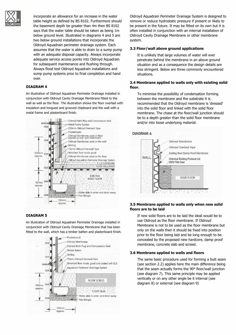
incorporate an allowance for an increase in the water table height as defined by BS 8102. Furthermore should the basement depth be greater than 4m then BS 8102 says that the water table should be taken as being 1m below ground level. Illustrated in diagrams 4 and 5 are two below ground installations that incorporate the Oldroyd Aquadrain perimeter drainage system. Each assumes that the water is able to drain to a sump pump with an adequate disposal capacity. Always incorporate adequate service access points into Oldroyd Aquadrain for subsequent maintenance and flushing through. Always flood test Oldroyd Aquadrain installations and sump pump systems prior to final completion and hand over.
DIAGRAM 4
An illustration of Oldroyd Aquadrain Perimeter Drainage installed in conjunction with Oldroyd Cavity Drainage Membrane fitted to the wall as well as the floor. The illustration shows the floor overlaid with insulation and tongued and grooved chipboard and the wall with a metal frame and plasterboard finish.
DIAGRAM 5
An illustration of Oldroyd Aquadrain Perimeter Drainage installed in conjunction with Oldroyd Cavity Drainage Membrane that has been fitted to the wall, which has a timber batten and plasterboard finish.
Oldroyd Aquadrain Perimeter Drainage System is designed to remove or reduce hydrostatic pressure if present or likely to be present in the future. It may be fitted on its own but it is often installed in conjunction with an internal installation of Oldroyd Cavity Drainage Membrane or other membrane system.
3.3 Floor/wall above ground applications It is unlikely that large volumes of water will ever penetrate behind the membrane in an above ground situation and as a consequence the design details are less stringent. Below are three commonly encountered situations.
3.4 Membrane applied to walls only with existing solid floor.
To minimise the possibility of condensation forming between the membrane and the substrate it is recommended that the Oldroyd membrane is 'dressed' into the solid floor and linked with the solid floor membrane. The chase at the floor/wall junction should be to a depth greater than the solid floor membrane and/or into loose underlying material.
3.5 Membrane applied to walls only when new solid floors are to be laid
If new solid floors are to be laid the ideal would be to use Oldroyd as the floor membrane. If Oldroyd Membrane is not to be used as the floor membrane but only on the walls then it should be fixed into position prior to the floor being laid and be long enough to be concealed by the proposed new hardcore, damp proof membrane, concrete slab and screed.
3.6 Membrane applied to walls and floors The same basic procedure used for forming a butt seam (see section 2.2) applies here the main difference being that the seam actually forms the 90° floor/wall junction (see diagram 7). This same principle may be applied vertically or on any other angle be it internal (see diagram 8) or external (see diagram 9)

An alternative method is to lap the floor membrane approximately 200mm up the wall membrane and apply 200mm Oldroyd Overseal Tape to join the membrane used on the floor to that used on the wall (see diagram 10).
NOTE: Oldroyd Studded Membranes are ideal to receive self levelling or conventional screeds as well as free floating timber based sheet material floor finishes. Oldroyd Xs Membrane is ideal to receive pumped screeds.
USING OLDROYD STUDDED MEMBRANE ON FLOORS If Oldroyd Studded Membrane is to be used on a floor alone and not in conjunction with a wall application the following procedure should be followed:
4.1 Laying Oldroyd Studded Membrane on a floor: Lay the membrane, with the dimples facing down, in lengths across the entire floor area to be covered joining each section to the adjoining piece with the relevant water/vapour proof seam as described in section 2.0. Make sure that the membrane is lapped up around the perimeter of the area as well as any penetrating columns etc to a height greater than the intended floor finish. Lay the floor finish and then trim off any excess membrane flush to the new floor finish. It is not necessary to fix the membrane to the floor, however if the intended floor finish requires fixing which necessitates puncturing the membrane the advice of our Technical Department should be sought.
DEALING WITH INCOMING SERVICE PIPE ENTRY POINTS AND PROTRUSIONS WHICH HAVE TO PENETRATE THE MEMBRANE
(see diagrams 11, 12 & 13)
Very often Oldroyd materials are used in locations where service pipes enter a building. Subject to their position this can be a point of weakness and therefore special attention is necessary. For the purposes of these instructions we shall refer to an incoming service as a pipe:
5.1 Preparatory work: Clean off any rust, dirt, grease etc. from the incoming service pipe and if necessary apply a primer. Before the detail may be formed first of all cut and fit the membrane around the pipe as close as possible. Make good the unavoidable cut in the
membrane using the butt seam technique (see section 2.2). Complete the fixing of the membrane to the wall in the normal fashion.
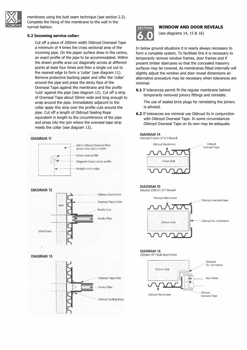
5.2 Incoming service collar: Cut off a piece of 200mm width Oldroyd Overseal Tape a minimum of 4 times the cross sectional area of the incoming pipe. On the paper surface draw in the centre, an exact profile of the pipe to be accommodated. Within the drawn profile area cut diagonally across at different points at least four times and then a single cut out to the nearest edge to form a 'collar' (see diagram 11). Remove protective backing paper and offer the 'collar' around the pipe and press the sticky face of the Overseal Tape against the membrane and the profile 'cuts' against the pipe (see diagram 12). Cut off a strip of Overseal Tape about 50mm wide and long enough to wrap around the pipe. Immediately adjacent to the collar apply this strip over the profile cuts around the pipe. Cut off a length of Oldroyd Sealing Rope equivalent in length to the circumference of the pipe and press into the join where the overseal tape strip meets the collar (see diagram 13).
WINDOW AND DOOR REVEALS (see diagrams 14, 15 & 16)
In below ground situations it is nearly always necessary to form a complete system. To facilitate this it is necessary to temporarily remove window frames, door frames and if present timber staircases so that the concealed masonry surfaces may be covered. As membranes fitted internally will slightly adjust the window and door reveal dimensions an alternative procedure may be necessary when tolerances are minimal:
6.1 If tolerances permit fit the regular membrane behind temporarily removed joinery fittings and reinstate.
The use of sealed brick plugs for reinstating the joinery is advised.
6.2 If tolerances are minimal use Oldroyd Xs in conjunction with Oldroyd Overseal Tape. In some circumstances Oldroyd Overseal Tape on its own may be adequate.
FREE WATER BEHIND THE MEMBRANE (Refer to BS8102)
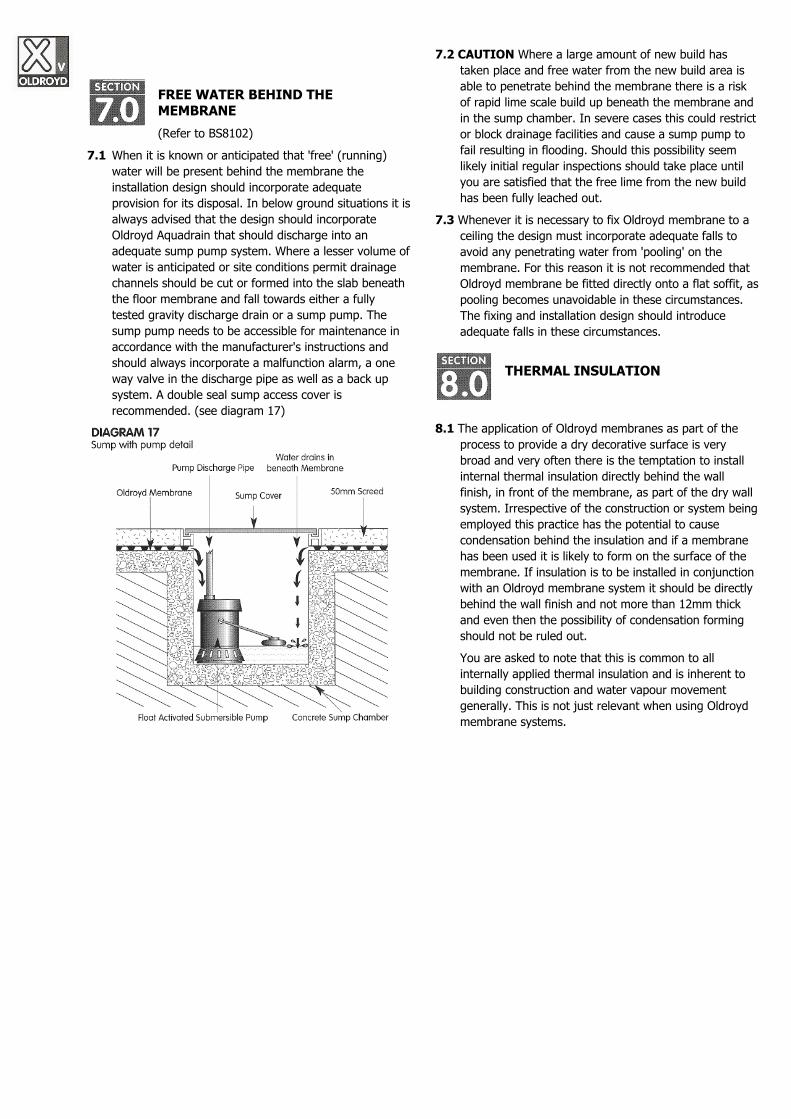
7.1 When it is known or anticipated that 'free' (running) water will be present behind the membrane the installation design should incorporate adequate provision for its disposal. In below ground situations it is always advised that the design should incorporate Oldroyd Aquadrain that should discharge into an adequate sump pump system. Where a lesser volume of water is anticipated or site conditions permit drainage channels should be cut or formed into the slab beneath the floor membrane and fall towards either a fully tested gravity discharge drain or a sump pump. The sump pump needs to be accessible for maintenance in accordance with the manufacturer's instructions and should always incorporate a malfunction alarm, a one way valve in the discharge pipe as well as a back up system. A double seal sump access cover is recommended. (see diagram 17)
7.2 CAUTION Where a large amount of new build has taken place and free water from the new build area is able to penetrate behind the membrane there is a risk of rapid lime scale build up beneath the membrane and in the sump chamber. In severe cases this could restrict or block drainage facilities and cause a sump pump to fail resulting in flooding. Should this possibility seem likely initial regular inspections should take place until you are satisfied that the free lime from the new build has been fully leached out.
7.3 Whenever it is necessary to fix Oldroyd membrane to a ceiling the design must incorporate adequate falls to avoid any penetrating water from 'pooling' on the membrane. For this reason it is not recommended that Oldroyd membrane be fitted directly onto a flat soffit, as pooling becomes unavoidable in these circumstances. The fixing and installation design should introduce adequate falls in these circumstances.
THERMAL INSULATION
8.1 The application of Oldroyd membranes as part of the process to provide a dry decorative surface is very broad and very often there is the temptation to install internal thermal insulation directly behind the wall finish, in front of the membrane, as part of the dry wall system. Irrespective of the construction or system being employed this practice has the potential to cause condensation behind the insulation and if a membrane has been used it is likely to form on the surface of the membrane. If insulation is to be installed in conjunction with an Oldroyd membrane system it should be directly behind the wall finish and not more than 12mm thick and even then the possibility of condensation forming should not be ruled out.
You are asked to note that this is common to all internally applied thermal insulation and is inherent to building construction and water vapour movement generally. This is not just relevant when using Oldroyd membrane systems.

USEFUL TIPS WHEN USING OLDROYD MEMBRANES, TAPES, SEALANTS AND FIXINGS.
9.1 Basic equipment requirements for installation Sharp knife and spare blades Measuring Tape Spirit level (500mm to 1m) Plumb Line / Chalk Line Club (lump) Hammer 2m straight edge Access equipment and adequate lighting Dry clean cloths to wipe surfaces clean Warm Air Gun Masonry drill with 10mm drill bit.
9.2 Procedure when using Oldroyd tapes & sealants It is recommended that a Warm Air Gun be used either to warm the membrane surface or the tape/sealant just prior to use as this greatly enhances the adhesive properties. These instructions therefore assume that surfaces to be joined, seamed or covered will have been warmed just prior to the application of Oldroyd tape and sealants. The use of vapour wipes in areas of high humidity is advised.
9.3 Before applying any sealant or tape onto a membrane always ensure that the surface is dry and clean.
9.4 If for any reason a horizontal join is necessary a butt
seam (see section 2.2) is normally adequate but if running water behind the membrane is anticipated then a correctly 'lapped and weathered' join should be formed for added protection.
9.5 Only use a club/lump hammer to insert Oldroyd Brick Plugs otherwise there is a risk that the head could shatter.
9.6 When using Oldroyd Brick Plugs with sealing rope 'collars' do not make up too many ahead otherwise they may become dust contaminated and/or adhere to each other. Consider using Oldroyd Compression Seal Washers.
9.7 When hanging membrane always plumb the first length for each run of wall. This greatly assists with subsequent vertical brick plug fitting, mechanical seam alignment and prevents an unpleasant visual appearance during installation.
9.8 In most circumstances it is normally better to position and hang the membrane first before attending to the more intricate details.
9.9 Galvanised dry wall fast frame system significantly reduces the brick plug requirement compared with a timber batten wall finish technique
The nature of a Cavity Drainage Membrane installation is such that it is not practically possible to produce exhaustive installation instructions. The
guidance notes contained in this document deal with the most commonly encountered installations. In the event of an unusual situation presenting
itself please contact our Technical Department for advice. Neither Oldroyd Systemer AS nor ChemBuild Ltd will accept liability for any loss or
damage, whether direct or consequential, occasioned by or arising out of inadequate or inappropriate installation of any Oldroyd materials.
Manufactured by: Oldroyd Systemer AS Kragero Noeringspark, 3766 Sannidal, Norway
Telephone: +47 35 98 75 50 Fax: +47 35 98 75 51
E-mail: [email protected]
Web: www.oldroyd.no
Distributed by: ChemBuild Ltd ChemBuild Ltd Unit 36A Bridge Street Sturminster Marshall BH21 4DB Dorset, United Kingdom
Telephone: +44 (0) 1202 601 701 Fax: +44 (0) 1202 604 300
Free Technical Support
01202 601701
ChemBuild Ltd Unit 36A Bridge Street Sturminster Marshall BH21 4DB Dorset, United Kingdom
Telephone: +44 (0) 1202 601 701
Fax: +44 (0) 1202 604 300
E-mail: [email protected]
Web: www.chemicalbuildingproducts.co.uk