
GUIDANCE INFORMATION ON DESIGN FOR PRESERVATION … Design Guidance for... · 1/7/2012 · GUIDANCE...
91
GUIDANCE INFORMATION ON DESIGN FOR PRESERVATION AND CORROSION CONTROL FOR STEEL HULLED VESSELS Prepared by Jim Miller BVT Surface Fleet (Vice Chairman)
Transcript of GUIDANCE INFORMATION ON DESIGN FOR PRESERVATION … Design Guidance for... · 1/7/2012 · GUIDANCE...

GUIDANCE INFORMATION ON DESIGN FOR
PRESERVATION AND CORROSION CONTROL
FOR STEEL HULLED VESSELS
Prepared by Jim Miller BVT Surface Fleet (Vice Chairman)

Marine Painting Forum Design Guidance

Marine Painting Forum Design Guidance
Marine Painting Forum
The Marine Painting Forum membership is drawn from a selection of various companies who have an interest in the supply of coatings, the preparation of surfaces prior to application, the application of these coatings to various structures and the protection media applied to maintain coated surfaces during the build cycle. The membership is not restricted to any one branch of industry but is open to all parties with an interest in preservation of marine structures.
With the exception of our Chairman, David M. Allison C.Eng, MRINA, RCNC who is an independent member, the current membership is drawn from the following list of companies:
Babcock Marine Devonport Limited
BMT Sea Tech Limited
BVT Surface Fleet (Construction and maintenance)
Defence Equipment & Support
Hempel Paints
Hodge Clemco Limited
International Paints
Interserve Industrial Services
Jack Tighe Limited
Leighs Paints
PPG PMC (formerly Sigma Paints)
Safinah
Scangrit
Temprotech Limited

Marine Painting Forum Design Guidance
1 of 88
Contents
1 Introduction 3
Scope 3
Purpose of the Guide 4
2 Corrosion Aspects 5 General Principles 5 Visual Indication of Types of Corrosion 9 Other Types of Corrosion 16 Principal Methods for Overcoming Corrosion 18
3 Structural Design Aspects Guidelines 19 General 19 Design Features to Avoid 19 Access for Preservation 27 Sharp Edges of Structure 28 Tank Stiffeners 29 Corrugated Bulkheads 29 Scalloped Corners 30 Suction Strums 31 Correct Means of Connecting Dissimilar Metals 32
4 Equipment and Component Installation Guidelines 33 General 33 Fasteners 33 Plated Fasteners 34 Deck Equipment/Fittings 35 Internal Equipment/Components 40 Pipes/Fittings in Confined Space 42 Connections to Steel/Aluminium Structures 44 Use of Corrosion Resistant Materials 44 Stainless Steels and High Nickel Alloys 44 Copper Based Alloys 46 Titanium 47 Aluminium Alloy 48 Fibre Reinforced Plastic 48
5 Surface Preparation Prior to Preservation 49 General Techniques 49 Standards 50 Containment 51 Blast Media 54
Marine Painting Forum Design Guidance
2 of 88
6 Application of Different Preservation for Corrosion Control 73
General 73 Requirements for Painting 73 Paint Application 74 Occupational Hygienic Considerations 75 Type of Paint Coating 76 Maintenance Painting 76 Powder Coatings 77 Summary 78
7 Quality Control 78 Measurement of Dry Film Thickness 79
8 Protection During Build/Refit 83
9 Related Documents 86

Marine Painting Forum Design Guidance
3 of 88
1. Introduction
1.1 Scope
This document is intended to be used as an aid to naval ships staff, shipbuilders and ship repairers, concerned with design, preservation, ship husbandry and repair of ships’ and submarine structures. It provides general guidance and information on:
The identification of corrosion mechanisms.
Potential problem areas.
Methods of improving corrosion performance.
Current good design practice.
Selection of materials.
Although corrosion problems in the ships’ and submarines are generally well understood and documented, the associated financial issues are less well appreciated. Much can be achieved at the design & build stage, to reduce the in-service ship husbandry workload and to maintain structural integrity, by paying much closer attention to detailed design and preservation issues.

Marine Painting Forum Design Guidance
4 of 88
1.2 Purpose
The purpose of this guidance document is to outline the general principles of corrosion and the various methods used to control it. Whilst the information is presented in the context of naval vessel construction and reflects current best practice, the underlying principals remain relevant to both the merchant fleet and static salt water based steel platforms. More detailed documents are referenced where appropriate. In general, this document is aimed at steel hulled vessels however many of the basic principals are pertinent to both aluminium and FRP/GRP hulled vessels.
This document addresses:
The types of corrosion which occur with the materials used for ship and submarine construction
Specific detail concerning equipment installation to the steel structure.
Surface preparation required prior to applying preservation treatments
Structural aspects of design for avoiding corrosion and simplifying the application of coatings and maintenance

Marine Painting Forum Design Guidance
5 of 88
2 Corrosion Aspects
2.1 General Principles
Most metals occur in nature as oxides or complex salts and the metal is extracted through the expenditure of considerable amounts of energy. Therefore, there is a tendency for them to try to revert to their natural state and this process is known as corrosion.
Corrosion is the degradation of the exposed surface of a metal due to reaction with its environment. Under atmospheric conditions metal surfaces are covered with a corrosion product which is thermodynamically stable with the environment. This mainly consists of an oxide but generally includes compounds containing atmospheric impurities such as sulphur, chlorides and water. This oxide can be thin and impervious where it becomes protective e.g. on titanium alloys, aluminium alloys or stainless steels. In other cases the oxide is porous and not protective e.g. rust on steel in damp air.
For steels immersed in water, regions of corrosion, passivation and immunity can be related to its potential LE and the pH of the environment in a Pourbaix diagram as shown in Figure 2.1
Figure 2.1
Simplified POURBAIX diagram (Potential/pH) for Fe-H20 System showing
regions of immunity, passivation and corrosion.
Here the oxide is not stable and corrosion of steel will occur in acids (low pH) and in strong caustic (high pH). Also there is a potential (voltage) below which steel is immune to corrosion.

Marine Painting Forum Design Guidance
6 of 88
There are conditions, with metals which are normally corrosion resistant, where the oxide cannot be repaired e.g. because there is insufficient oxygen or the oxide is not stable in a particular environment such as acids and corrosion will occur. This is the driving force behind the mechanism of crevice corrosion.
Protective oxide films can be broken down by aggressive species such as chlorides, fluorides and sulphur, where local galvanic cells are set up on the metal surface and highly acidic conditions can occur at the site of the local contamination due to formation of, for example hydrochloric acid, hydrofluoric acid or sulphuric acid and localised corrosion occurs as indicated in Figure 2.1. This is the main cause of pitting.
Combinations of metals can also result in corrosion problems. All metals when immersed in an electrolyte adopt a potential which is a voltage quoted against a standard reference electrode (e.g. silver/silver chloride or calomel) For steels in sea water at pH8 this potential is between -600 to -700 mV against a calomel reference electrode. In Figure 2.1 Iron can be made immune to corrosion by lowering the voltage to -800mV (-0.8 volts) at pH’s below 10.
The potentials in sea water for a range of metals can be listed to form a galvanic series (quoted against a calomel reference electrode) see Figure 2.2. It should be noted that potentials vary with changes in flow rate and temperatures. An example is the polarity reversal in certain domestic water systems between zinc and steel at temperatures above 600C leading to rapid corrosion of the steel

Marine Painting Forum Design Guidance
7 of 88
Volts Saturated Calomel Half-Cell Reference Electrode
Volts vs. Std. Hydrogen Sat. Cu/CuSO4 Sat Calomel. (also Ag/AgCl in 20 ohm-cm seawater)
Figure 2.2
Alloys are listed in order of the potential they exhibit in flowing sea water. Certain alloys indicated by the symbol: in low-velocity or poorly aerated water, and at

Marine Painting Forum Design Guidance
8 of 88
shielded areas, may become active and exhibit a potential near -0.5 volts
Figure 2.3
When metals of dissimilar electrochemical potential are electrically coupled together in the presence of a conducting electrolyte such as sea water the more negative, or active, of the two metals will corrode at an accelerated rate. The more positive, or noble, of the two metals will not suffer from corrosion. This mechanism is called galvanic corrosion.
The mechanism of galvanic corrosion, illustrated by the electrochemical cell in Figure 2.3, comprises of four essential components:
a. ANODE - a metal which is more negative, or active, than the cathode. b. CATHODE - a second metal which is more positive, or noble, than the anode. c. ELECTROLYTE - a solution which is capable of carrying an electrical current
between the anode and cathode, e.g. sea water. d. ELECTRICAL PATH - an electrically conducting path between the anode and
the cathode
Important applications in relation to steel are:
a Steel can be prevented from corroding by connecting it to a less noble metal or lowering the potential into the immune region of Figure 2.1. This is the principle of cathodic protection by sacrificial anodes, or impressed current (IC) systems.
b Scale formed on steel arising from the manufacturing process is electrically conducting and very noble and can cause severe corrosion of the steel. These must be removed prior to any preservative treatment.
c Corrosion can be prevented through keeping the environment away from the steel surface by using coatings.
d Steel can be prevented from corroding by the application of hot spraying of organic metals e.g. zinc or aluminium.

Marine Painting Forum Design Guidance
9 of 88
2.2 Visual Indication of Types of Corrosion
Types of corrosion: there are several types of corrosion, the most common found are summarised below.
More details on definitions and examples are highlighted on paragraphs 2-6 to 2-1 1.
Common types of corrosion found topside are:
1. Uniform or General Corrosion
2. Pitting Corrosion
3. Crevice Corrosion
4. Galvanic Corrosion
5. Exfoliation

Marine Painting Forum Design Guidance
10 of 88
UNIFORM CORROSION DEFINITION:
Uniform attack over large areas of metal surface. Generally due to the presence of moisture and oxygen. Therefore this is the most common form of corrosion over a large area.
EXAMPLES:
1 Uniform rusting of unpainted or poorly painted steel
2 Rusting of inaccessible deck/bulkhead
3 Rusting of poorly preserved wet spaces
4 Rusted fasteners
CAUSES: 1 Corrosion builds up on the entire surface due to formation of a non protective
oxide. Because corrosion is not stopped the oxide (e.g... rust) becomes thicker as shown in Figure 2.4.
Figure 2.4 Formation of General Corrosion
Marine Painting Forum Design Guidance
11 of 88
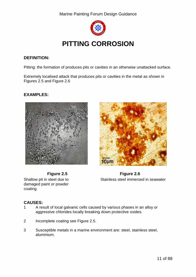
PITTING CORROSION DEFINITION: Pitting: the formation of produces pits or cavities in an otherwise unattacked surface.
Extremely localised attack that produces pits or cavities in the metal as shown in Figures 2.5 and Figure 2.6 EXAMPLES:
Figure 2.5 Figure 2.6
Shallow pit in steel due to Stainless steel immersed in seawater
damaged paint or powder
coating.
CAUSES: 1 A result of local galvanic cells caused by various phases in an alloy or
aggressive chlorides locally breaking down protective oxides. 2 Incomplete coating see Figure 2.5. 3 Susceptible metals in a marine environment are: steel, stainless steel,
aluminium.

Marine Painting Forum Design Guidance
12 of 88
CREVICE CORROSION DEFINITION: Localised attack of a metal surface due to variations in electrolyte concentration (usually differential aeration cell or metal ion concentration cell) EXAMPLES:
Corrosion attack of Stainless Steel nut/bolt & bare aluminium under nylon washer. See Figure 2.7. Stainless steels are very prone to crevice corrosion & corrode within the crevice due to differential aeration Copper alloys corrode just outside of the crevice due to metal ion concentration cell
Figure 2.7 Aluminium would be better protected with proper use of coatings and sealants.

Marine Painting Forum Design Guidance
13 of 88
Figure 2.8 CAUSES: Crevice: caused by physical irregularities on metal surfaces. Usually caused by narrow gaps which restrict access of oxygen or electrolyte. See Figure 2.8. a) A deficiency of oxygen. Metal cannot repair oxide, hydrochloric acid formed if
sea water present and corrosion occurs. b) Increase in metal ion concentration in the crevice resulting in differences of
potential on the surface of the same metal. More common in copper based alloys.

Marine Painting Forum Design Guidance
14 of 88
GALVANIC CORROSION DEFINITION: Galvanic corrosion (also called ' dissimilar metal corrosion' or wrongly 'electrolysis') refers to corrosion damage induced when two dissimilar materials are coupled in a electrolyte. When a galvanic couple forms, one of the metals in the couple becomes the anode and corrodes faster than it would by itself, while the other becomes the cathode and corrodes slower than it would alone. For galvanic corrosion to occur, three conditions must be present:
1. Electrochemically dissimilar metals must be present 2. These metals must be in electrical contact. 3. The metals must be exposed to an electrolyte
EXAMPLE - Steel Coupling corroding:
Figure 2.9 1. Sacrificial anodes which corrode to protect a steel structure 2. Mill scale on steels will cause severe corrosion of exposed steel surfaces. 3. Selective phase corrosion can occur in multi phased alloys e.g. dezincification
of brass.

Marine Painting Forum Design Guidance
15 of 88
CAUSES: Greatest damage occurs when the anode surface is much smaller than the cathode surface and the cathode is much more noble than the anode.
Four factors must be present for corrosion to occur: a) Anode: a metal which is more susceptible to corrosion b) Cathode: a second metal which is less susceptible to corrosion and therefore
does not deteriorate. c) Electrical path: a metallic contact between the anode and cathode.
d) Electrolyte: a solution which is capable of carrying an electrical (ionic) current between the anode and cathode
EXFOLIATION DEFINITION:
Corrosion products building up along grain boundaries exert pressure between the grains and the end result is a lifting or leafing effect. Aluminum alloys that have been extruded or otherwise worked heavily, with a microstructure of elongated, flattened grains, are particularly prone to this damage. The damage often initiates at end grains encountered in machined edges, holes or grooves and can subsequently progress through an entire section. EXAMPLE:
In this particular form of intergranular corrosion the expansive force of insoluble corrosion products tends to force the grains apart and leads to exfoliation corrosion, sometimes known as lamellar or layer corrosion. In extreme cases, the edges of the affected area are leaf like and resemble the separated pages of a wetted book that has become swollen and begun to open up as shown in Figure 2.10
Figure 2.10 Heavily Worked Aluminium Plate

Marine Painting Forum Design Guidance
16 of 88
2.3 Other Types of Corrosion
Microbial Corrosion DEFINITION:
Microbial corrosion (also known as 'bacterial corrosion') often occurs primarily within fuel tanks as a consequence of sulphate-reducing bacteria.
Cause
The organisms are, in the main, introduced to the ships tanks when re-fuelling with contaminated diesel or Avcat. As the organisms feed on the organic compounds, they produce hydrogen sulphide as waste matter. This sulphide is then transformed into sulphuric acid which can have catastrophic results on the tank structure.
Under Lagging Corrosion
Insulation products are mainly manufactured from mineral wool type materials and as such have a rather open weave pattern which can allow the retention of moisture against the metal substrate. If the metal is left un-painted i.e. bare, then there is a substantial risk of corrosion being induced. The rate of corrosion is proportional to temperature up to 110o C with corrosion rates up to 2.5 mm per year.
Stress Corrosion Cracking
Stress corrosion cracking (SCC) is the unexpected sudden failure of normally ductile metals or tough thermoplastics subjected to a tensile stress in a corrosive environment, especially at elevated temperature in the case of metals. SCC is highly chemically specific in that certain alloys are likely to undergo SCC only when exposed to a small number of chemical environments. The chemical environment that causes SCC for a given alloy is often one which is only mildly corrosive to the metal. Hence, metal parts with severe SCC can appear bright and shiny, while being filled with microscopic cracks. This factor makes it common for SCC to go undetected prior to failure. SCC often progresses rapidly, and is more common among alloys than pure metals. The specific environment is of crucial importance, and only very small concentrations of certain highly active chemicals are needed to produce catastrophic cracking, often leading to devastating and unexpected failure.
The stresses can be the result of the crevice loads due to stress concentration, or can be caused by the type of assembly or residual stresses from fabrication (e.g. cold working); the residual stresses can be relieved by annealing.
Some examples of materials/environment combinations which have proved susceptible to stress corrosion in the past are:

Marine Painting Forum Design Guidance
17 of 88
a Copper based alloys exposed to environments containing ammonia.
b 300 series austenitic stainless steels, such as type 304 or 316, in the marine environment at temperatures above 60o C
c High strength steels in sour gas i.e. a high concentration of hydrogen sulphide (H2S) in the atmosphere.
d High strength aluminium and titanium alloys in chloride containing environments.

Marine Painting Forum Design Guidance
18 of 88
2.4 Principal Methods for Overcoming Corrosion
The main methods for avoiding or combating corrosion and the practicality of each method for preserving ship and submarine structures are summarised below:
1 Changing the pH or the chemistry of the environment – not practical for exposed structures however vapour inhibitors can be used in small enclosed spaces.
2 Changing the potential of the metal so that it is in the immune region of Figure 2.1. The basis of cathodic protection by sacrificial anodes or impressed current cathodic protection (ICCP) systems is used for submerged surfaces but can be for topsides by using organic metal spray systems of zinc or aluminium. Recent developments show that using inorganic zinc or aluminium rich epoxies (87% metal in the dry film) gives comparable results.
3 Use of materials with improved corrosion inhibiting performance in the marine environment. Many of the metal alloys which are considered to have good corrosion performance are relatively expensive and, to date, have only been used for critical applications, Non-metallic materials, such as Fibre Reinforced Plastic (FRP), can be used economically in many applications where they offer the required strength and durability without the corrosion problems of metals. It should be noted that the use of FRP in the manufacture of weatherdeck fittings reduce the wholeship signature of warships as they have greatly reduced radar signature.
4 Remove the environment (i.e. aqueous solutions) from the metal surface. This is the basis for all paint/coating systems which provide a barrier, between metal and atmosphere, and is the most common method used. An extension of this is the use of de-humidification. If the relative humidity is dropped below 30% rusting of steel is unlikely to occur. This method has been used to “moth ball” the internal surfaces of laid up ships.
5 In areas such as bilge keels, the painting of internal surfaces is not required as these items are fully welded structures thus any contained oxygen will become rapidly depleted and no further corrosion will occur.
6 Design to avoid water traps and provide access for maintenance thus enhancing the ease of coating application.

Marine Painting Forum Design Guidance
19 of 88
3. Structural Design Aspects Guidelines
3.1 General
This section consists of various aspects of design that have an impact on the long term corrosion resistance of ships structure. It is a series of guidelines which, if properly applied at stage 1 design, will effectively reduce the requirement for re-application of coatings thereby decreasing the attendant (and costly) maintenance work load. Detailed attention, if considered at an early design stage, will in turn obviate many of the problems which cause corrosion.
3.2 Design Features to Avoid
3.1.1 Dissimilar metals (as previously discussed) cause corrosion and husbandry nightmares. The following pictures show examples of rust staining on painted surfaces because of poor compatibility in material selection:
Figure 3.1 Rust Staining from Flange bolts

Marine Painting Forum Design Guidance
20 of 88
Figure 3.2 S/S on MS Figure 3.3 Brass in MS
Figure 3.4 Plasticised Wire Mesh Breaking Down With Use

Marine Painting Forum Design Guidance
21 of 88
Figure 3.5 Manufacturers Nameplate with incorrect Fasteners
Figure 3.6 Generic Deck Connection Issue
Marine Painting Forum Design Guidance
22 of 88
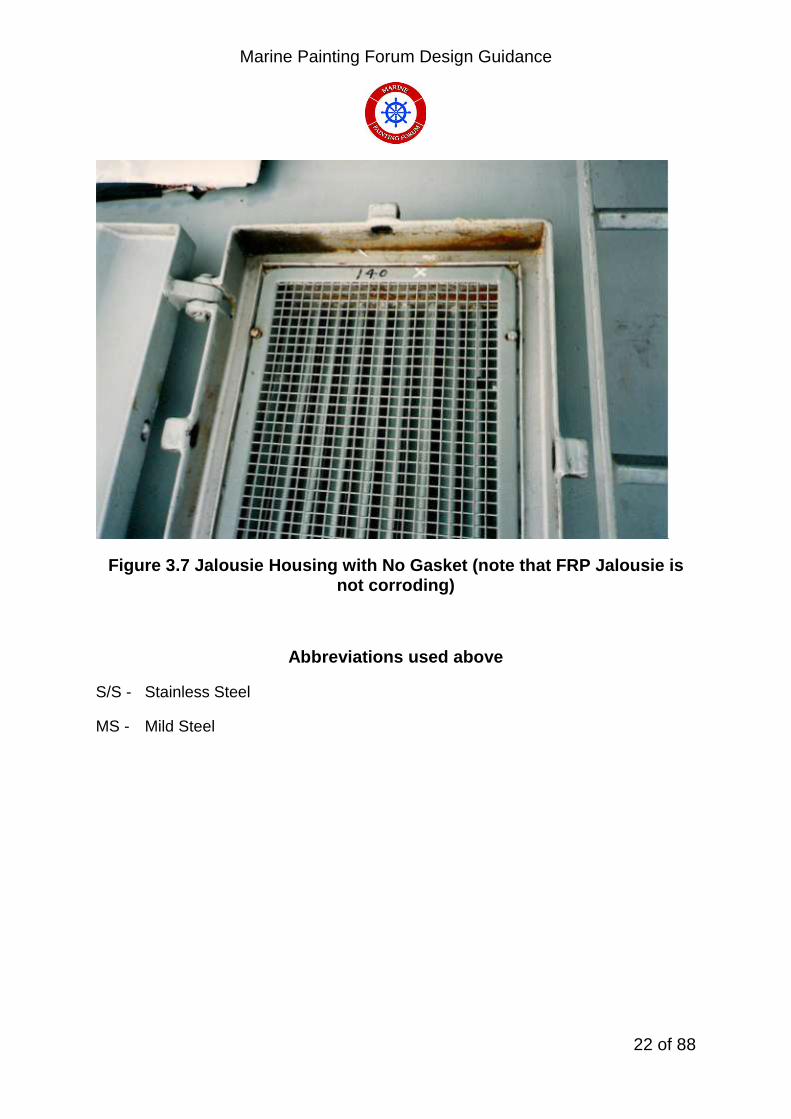
Figure 3.7 Jalousie Housing with No Gasket (note that FRP Jalousie is not corroding)
Abbreviations used above
S/S - Stainless Steel
MS - Mild Steel

Marine Painting Forum Design Guidance
23 of 88
3.1.2 The following Figures are examples of design flaws which favour corrosion and solutions to overcome the problem.
Main features are:
Access for maintenance. See Figure. 3.8 and Figure 3.9
Bad drainage. See Figure 3.10 and Figure 3.11
Designs which cause formations of crevices where water can penetrate resulting in corrosion that is not evident until perforations occur thus inducing weakness leading to ultimate failure. See Figure 3.12 and Figure 3.13.
Deck connections of pillars are prone to mechanical damage and the potential for water splash. Therefore, extreme care must be taken during welding process coupled with correct surface preparation and a reliable high build paint system is essential. See Figure 3.14.
Overlapped joints are to be designed for water shedding and fully caulked or insulated as appropriate. See Figure 3.15.
Adequate insulation is required to be fitted to all systems that contain fluids or gases that are outwith the ambient condition to ensure that condensation is kept to a minimum. See Figure 3.9.
Figure 3.8

Marine Painting Forum Design Guidance
24 of 88
Figure 3.9 This picture shows not only Dissimilar Metal Corrosion but also poor location leading
to inaccessibility to perform husbandry tasks. The inadequate insulation i.e. bare
flanges is also contributing to the preservation nightmare.

Marine Painting Forum Design Guidance
25 of 88
Storage tanks should be designed to allow complete drainage
Figure 3.10 Good Practice Figure 3.11 Bad Practice
Crevices to be filled to prevent ingress of liquid
Figure 3.12 Open Tack Weld Figure 3.13 Filled Tack Weld
Bad Practice Good Practice

Marine Painting Forum Design Guidance
26 of 88
Protection at base of Pillars
Figure 3.14
Bad Practice Good Practice
Overlapping of joints to Prevent Water Accumulation
Figure 3.15

Marine Painting Forum Design Guidance
27 of 88
3.3 Access for Preservation
Ideally, all compartments within the ship are to have 2 means of access opening be it doors, hatches, scuttles or manholes. Logically these openings are to be at opposite ends of the compartment thus ensuring a means of escape in a fire. As well as escape, these openings permit access for environmental controls to be fitted during the application of coatings. e.g. vent trunking, paint lines etc.
Certain locations within the structure, for structural integrity, contain closely spaced stiffening and are thus deemed to be “difficult” areas for coating applications. Examples of these spaces are:
Double bottom tanks
Forepeak tanks
Fuel filling trunks
Cofferdams.
Encapsulated areas.
Other areas of the ship, due to their locality, have only one access opening. These areas can present great difficulty in granting access for preservation and or inspection. When working within these areas, the rules for confined space working have to be rigorously applied i.e. planning off the work, gas freeing of the space, sentries posted and the first aid team made aware of operations.
At the design stage, careful consideration must be given to provide maximum access to compartment and restricted areas. For Royal Naval vessels this is to be done in accordance with Def Stan 02-149 – Access Policy in Surface Ships.
Adequate access facilities must be provided around equipment in all compartments to ensure that paint application and preservation can be carried out and to also ensure that during ships life adequate cleaning can be conducted thus avoiding dirt/corrosion traps.
A few examples are:
Behind and beneath air/gas bottle stowages
Areas between pipe brackets and pipework
Areas between systems and structure
Undersides of structural members
Marine Painting Forum Design Guidance
28 of 88
All interfaces between structure and equipment seating.
Access must be sufficient to allow access for application of paint by means of brush, roller or (preferably) spray.
Access for maintenance must be designed in. For an example of poor access see Figure 3.9.
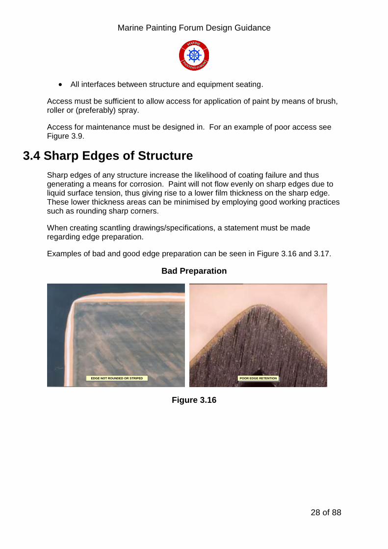
3.4 Sharp Edges of Structure
Sharp edges of any structure increase the likelihood of coating failure and thus generating a means for corrosion. Paint will not flow evenly on sharp edges due to liquid surface tension, thus giving rise to a lower film thickness on the sharp edge. These lower thickness areas can be minimised by employing good working practices such as rounding sharp corners.
When creating scantling drawings/specifications, a statement must be made regarding edge preparation.
Examples of bad and good edge preparation can be seen in Figure 3.16 and 3.17.
Bad Preparation
EDGE NOT ROUNDED OR STRIPEDEDGE NOT ROUNDED OR STRIPED
POOR EDGE RETENTIONPOOR EDGE RETENTION
Figure 3.16

Marine Painting Forum Design Guidance
29 of 88
Good Preparation
GOOD EDGE RETENTION
EDGE ROUNDED AND STRIPED
Figure 3.17
3.5 Tank Stiffeners
Tank structures, in general, cause problems for ship’s painters by the fact that they have a large number of return (throat of ‘T’ bars etc) edges that have to be protected. Preservation of tanks always presents difficulties for painters and it is further exacerbated by the configuration of pipework systems, valves and fittings etc.
If possible, consideration is to be given to the fitting of stiffeners to the externals of non structural tanks thus easing the burden on the applicators of preservation systems. This is of particular relevance to small auxiliary tanks that are fitted independently to the main ship’s structure.
3.6 Corrugated Bulkheads also known as Swedged Bulkheads.
Corrugated bulkheads unlike normally stiffened bulkheads have a minimum number of edges that require to be dressed for painting. This is due to the fact that there are no stiffeners welded to the plate as the plate corrugations provide the required strength. See Figure 3.18

Marine Painting Forum Design Guidance
30 of 88
Example of a Large Container Ship’s Corrugated Bulkhead.
Figure 3.18
3.7 Scalloped Corners
Poor drainage within the ships structure leads to pooling water and therefore induced corrosion. At all welded junctions of stiffening bracketry (beam knees etc) a cut out (mousehole) of at least 25mm must be cut. This cut-out fulfils two functions, the first is continuity of welding which reduces induced heat cracking and the second function of providing a low level drain hole thus allowing all liquids to drain to lowest point of structure as shown in Figure 3.19.
Mouseholes require an extra degree of attention to edge cut and preparation to ensure that the internal surface of the cut is completely coated to system specification thus giving complete full good edge retention.

Marine Painting Forum Design Guidance
31 of 88
Figure 3.19
3.8 Suction Strums
Suction strums, as fitted to the ballast and bilge suction pipes, are to be fitted to the lowest part of the tank/bilge area. All structural members are to have drain holes fitted to facilitate the drainage of fluids to the collection point.
No small bore pipework is to be fitted behind strums thus ensuring that correct preservation means can be carried out.
Strum suctions are to be fitted with “Elephant’s Foot” fitting to ensure that the maximum amount of fluid can be drained from the tank.

Marine Painting Forum Design Guidance
32 of 88
3.9 CORRECT MEANS OF CONNECTING DISSIMILAR METAL:
Figure 3.20 Typical ‘Kelocouple’ Arrangement
In Naval shipbuilding, it is common for superstructures to be manufactured from aluminium. In order that the aluminium structure can be safely welded to the steel structure, and provide the required strength, an interface piece must be used. The interface is traditionally referred to as a ‘Kelocouple’ system, which is an explosively bonded joint comprising a tri-metallic sandwich of steel/aluminium/aluminium alloy as shown in Figure 3.20.

Marine Painting Forum Design Guidance
33 of 88
4 Equipment and Component Installation Guidelines
4.1 General This section addresses specific components and materials which may be used in ship and submarine construction providing greater detail on current designs and methods used for overcoming corrosion.
4.2 Fasteners The requirements for threaded fasteners for general Royal Naval use are given in Def Stan 02-862. In every application it is desirable that all components of a fastening system are made from electrochemically compatible material, an example of incompatible fasteners would be the use of a steel washer with a stainless steel or nickel/copper alloy nut and bolt. Bimetallic corrosion as described in Section 2 may occur if incompatible fastener materials and deck or bulkhead materials are not electrically insulated from each other.
Figures 4.1 to 4.4 illustrate typical ways fasteners are assembled for mounting purposes. The most common fastening applications on exterior structural areas are:
Steel to steel Steel to Aluminium alloy Aluminium alloys to aluminium alloy
Generic situations for fasteners are:
Items mounted to steel deck or bulkhead bracket
(a) When bolt is vertical, the bolt head should always be on the top whenever possible
(b) All bolts should point in the same direction
(c) One to two and a half threads should show past the nut

Marine Painting Forum Design Guidance
34 of 88
Items mounted by bolt into a threaded hole in the deck or bulkhead Item mounted on deck or bulkhead stud
Corrosion resistant materials used for Naval fasteners are discussed in Section 4.6. The following fastener materials have restricted usage:
Brass fasteners are not to be used in exterior applications because the material suffers from dezincification in contact with sea water which results in a loss of strength
Type 316 austenitic steel fasteners including Grade At-BC as specified in BS EN ISO 3606-1 are not to be used where they will be immersed in sea water because the material is prone to crevice corrosion. However on weather decks where the risk of crevice corrosion is reduced these fasteners may be used
Aluminium silicon bronze is only to be used where a low magnetic permeability is required and no acceptable alternative is available
The requirements for steel fasteners for Royal Naval use at high temperatures, e.g. in steam pipe systems, are laid out in DEF STAN 02-862. The requirements for non-ferrous fasteners for Naval specified purpose use are laid out in DEF STAN 02-862. .
4.3 Plated Fasteners
The requirements for plated fasteners for General Royal Naval Purposes are laid out in DEF STAN 02-862. In the past steel fasteners have been coated in cadmium to provide some corrosion resistance because the coating protects the steel sacrificially as described in Section 2. Cadmium plated fasteners are no longer to be used for general purposes because of the health hazards associated with cadmium and its corrosion products. Cadmium plating is only to be used where it has been demonstrated that there is no acceptable alternative available DEF STAN 03-36 refers.
Zinc plating offers some resistance to corrosion in the same way as cadmium, but only protects fasteners immersed in sea water or subjected to sea spray for a very short period of time. The zinc plating is, therefore, only sufficient protection whilst the fasteners are being stored/assembled and additional protection, such as a paint system, is required to prevent corrosion of the assembly while in use. Zinc plated steel fasteners are not to be used for applications where the temperature may rise above 60oC because the electro-chemical polarity of zinc and steel reverses so that zinc no longer protects the steel sacrificially but actively promotes rusting.

Marine Painting Forum Design Guidance
35 of 88
4.4 Deck Equipment/Fittings
The installation of deck equipment and fittings should be carefully planned and their fitting should be left, where possible, until all building/repair work has been completed.
All mounting surfaces in Royal Navy vessels are to be prepared in accordance with BR 3939 prior to the fitting of equipment.
Any chipped or damaged preservation systems are to be suitably repaired by feathering and recoating.
The necessity to apply Stripe Coatings, indicated in Section 5, must not be neglected.
When mounting components anti-seize compound is to be applied to all fastener threads and an approved sealant is to be applied to all mating surfaces.
Figures 4.1 to 4.4 show typical mounting methods. The use of sleeves as shown in Figures 4.1 to 4.4 option (b) is preferred for new fits but on existing items, where this is not practical, the arrangements in Figures 4.1 to 4.2 option (a) are to be used.
In many instances fixtures and fittings are constructed of mild steel when the use of non-corrodible alternatives would be better. Typical examples are pipes, cable trays, clamps, ladders, vent terminals, jalousies etc. Many of these items are not capable of being preserved satisfactorily. Certain items such as clamps and cable trays are in intimate contact with other surfaces, so they and the contacting surface can not be preserved effectively after assembly. Items such as ladders, are by necessity subjected to mechanical damage and they are intrinsically difficult to preserve because of their shape, Figures 5.14 and 5.22 refer.
Ladders should be produced with solid side stringers to reduce the number of sharp edges Figure 4.5 refers.
Carrier plating is traditionally manufactured from either galvanised mild steel or aluminium and very quickly becomes prone to corrosion, partly due to the mounting stools and partly due to the cable clips and fastenings. When the electric cables have been clipped to the carrier plating, by virtue of the fact that electric cable is not to be painted, it is almost impossible to re-preserve the carrier plating and stools. It would be preferable to have carrier plating manufactured from FRP or stainless steel where ever possible. Where practical, carrier plating should be designed out and cable brackets used when support is required for large cable runs. Figure 4.6 refers

Marine Painting Forum Design Guidance
36 of 88
Deck or Bulkhead Stud
Figure 4.1

Marine Painting Forum Design Guidance
37 of 88
Deck or Bulkhead Stud
Figure 4.3

Marine Painting Forum Design Guidance
38 of 88
Steel Deck or Bulkhead Bracket
Figure 4.4
Steel Ladders
Bad Practise Good Practise
Figure 4.5

Marine Painting Forum Design Guidance
39 of 88
Electrical Carrier Plate
Cable trays are to be made from FRP or stainless steel wherever possible. Where practicable, cable trays are to be designed out and cable brackets and nylon ambits used when support is required for larger cable runs
Figure 4.6
Showing: top Cable Tray, left Cable Carrier and right Nylon Ambit

Marine Painting Forum Design Guidance
40 of 88
4.5 Internal Equipment/Components From a preservation viewpoint, there are two major considerations: 1. How and when to preserve the fixtures and fittings which go into the spaces. 2. How and when to preserve the boundaries of the space i.e. the compartment
itself.
In an ideal situation, the compartment itself should be preserved prior to the installation of any fittings. The preservation system should be designed for long life, capable of withstanding some mechanical damage likely during installation of fittings, and should be repairable after installation of fittings. The fittings, supports and bolts should ideally be made from non-corrodible material. Pipework should have sufficient break points to facilitate installation and removal. The use of bolted connections and fittings, which themselves can be broken down into smaller component parts, greatly reduces the need for hot work in compartments during the initial new build, and subsequent maintenance periods. The reduction and possible eradication of welding can be expected to significantly reduce the amount of repairs necessary on both the weld areas and damaged areas. However mechanical damage occurring during installation and commissioning of equipment cannot be totally avoided, but may be minimised by suitable protection, particularly on walking and horizontal areas
4.6 Support Structure/Brackets
Any support steelwork must receive the same treatment as the main steel work. In confined areas where brackets and pipe supports are required the protective coatings/paint systems cannot always be maintained effectively. In such cases it is prudent that consideration be given to using corrosion resistant materials such as stainless steel, copper alloys or composites. Figure 4.7 and Figure 4.8 refer. Under damp and immersed conditions bimetallic corrosion can occur at exposed joints of dissimilar metals.
Where pipe support brackets are connected to the pipework the joints are to be sealed to prevent the ingress of moisture Figure 4.7 and Figure 4.8 refer. The following standards should be referenced for details of preparation and applicable paint systems:
BS 7079
BR 3939
WARPAINT magazine as issued by DES SESea-MT

Marine Painting Forum Design Guidance
41 of 88
Support Structure/Brackets
Figure 4.7
Figure 4.8
Support Brackets

Marine Painting Forum Design Guidance
42 of 88
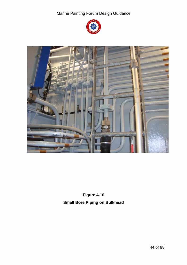
4.7 Pipes/Fittings in Confined Spaces Where a large number of pipes, especially those of small bore, are in a confined space it is extremely difficult to maintain the protective coatings of the pipes and their fittings. Stainless steel, copper alloys or composite pipes should be considered instead of coated carbon steel pipework and fittings. Figure 4.9 and Figure 4.10 refer. It should be noted that Admiralty Pipework Standards BR3013(1 and 2) specify the use of carbon steel pipework for steam, fresh water, oil and LP air systems. Stainless steel should not be considered where temperatures in the system are likely to exceed 300o C (e.g. diesel and G.T. exhaust systems) All pipework, with the exception of stainless steel, is to be fully coated with a suitable paint system and pipe clamps/brackets are to be coated with a sealant before fitting to prevent ingress of moisture between the clamp and pipework.

Marine Painting Forum Design Guidance
43 of 88
Pipework and Fittings in Confined Spaces
Figure 4.9
Cables and Pipes run vertically
Marine Painting Forum Design Guidance
44 of 88
Figure 4.10
Small Bore Piping on Bulkhead

Marine Painting Forum Design Guidance
45 of 88
4.8 Connections to Steel/Aluminium Structures
Insulated fasteners should be used as shown in Figures 4.1 to 4.4 option (b). Bimetalic strips are to be fitted to allow for welding to the steel and aluminium structures. These bimetalic strips are to be painted.
4.9 Use of Corrosion Resistant Materials
Corrosion resistant materials tend to be used for small critical components for ship and submarine construction where the increased cost can be justified. Structural components are usually made from steel. Aluminium alloys have been used to reduce top weight. Fibre Reinforced Plastics (FRP) are used for MCMV’s to reduce the magnetic signature with the added advantage of being completely corrosion resistant and as such should be used for other weatherdeck applications in normal steel hulled vessels. These materials can be split into four main groups:
Stainless steels and High Nickel Alloys Titanium Aluminium Alloys Fibre Reinforced Plastics (FRP)
4.9.1 Stainless Steels and High Nickel Alloys Available as austenitic, martensitic, ferritic and duplex alloys. The most widely available are the austenitic type 300 series. These alloys rely on a thin impervious oxide to provide corrosion protection. The resistance to crevice corrosion is dictated by alloy composition where molybdenum is particularly significant.
Grades used for fasteners are:
Austenitic Stainless steel to BS EN ISO 3606-1 (nuts and bolts) (2-3%Molybdenum)
Austenitic Stainless steel to BS EN ISO 10088 X5CrNiMo 17-12-2 (washers) (2-2.5% Molybdenum)
None of these alloys are immune to crevice corrosion where rates of up to 0.1mm/year can be expected (it should be noted that in severe condition, crevices
Marine Painting Forum Design Guidance
46 of 88
rates of greater than 0.1mm/year can be experienced) and all may suffer from chloride stress corrosion cracking above 600 C. Other stainless steels or high nickel alloys containing approximately 6% Mo have virtually complete immunity to crevice corrosion but at increased cost. These include:
Alloy 625 (high nickel alloy)
Zeron 100 (duplex stainless steel)
254 SMo (duplex stainless steel)
Fasteners made from all of these alloys are prone to galling and should be assembled with an anti-seize compound.
Nickel copper alloys are used for fasteners, valves and heat exchangers. Alloys available include:
Nickel copper alloy Monel 400 to BS 3076 NA18
Nickel copper alloy Monel K500 to BS 3076 NA13
Both these alloys suffer from crevice corrosion with rates of up to 0.5mm/year for NA13 and 0.05mm/year for NA18.
NA 13 is used for nuts and NA 18 used for bolts. Both these alloys can suffer from galling and anti-seize compound should be used for assembly. These alloys will cause galvanic corrosion in aluminium alloys, steels and copper alloys.

Marine Painting Forum Design Guidance
47 of 88
4.9.2 Copper Based Alloys
Copper based alloys are used extensively for applications in intimate contact with seawater such as pipework, heat exchangers and fixtures & fittings subject to immersion. Copper based alloys commonly employed by the Royal Navy are illustrated in Table 1.
Type of Alloy Procurement
Specification
Typical Applications
90/10 copper nickel alloy DEF STAN
02-779
Pipework for seawater systems, hydraulic systems and heat exchangers
70/30 copper nickel alloy DEF STAN
02-780
High pressure seawater pipework,
HP air and Hydraulics
Cast nickel aluminium bronze
DEF STAN
02-747
Seawater system components, valve bodies, propellers
Wrought nickel aluminium bronze
DEF STAN
02-833
Fasteners and components which operate in seawater
Cast Gunmetal DEF STAN
02-830
General purpose valve bodies not subject to high fluid velocity or shock loading etc.
Aluminium silicon
bronze
DEF STAN
02-834
Should only be used when a low magnetic permeability is essential and no alternative material is available.
Table 1 Copper based alloys commonly used by the Royal Navy
These alloys are more noble than steel and will cause galvanic corrosion of the steel alloys unless isolated or cathodically protected.
Marine Painting Forum Design Guidance
48 of 88
4.9.3 Titanium Used for heat exchangers and for fasteners in MCMV’s. Alloys normally used are: Commercial purity titanium (tubing to DEF STAN 02-310 and for bolts in MCMV’s Alloy Ti - 6A1 - 4V for high strength These alloys have complete immunity to crevice corrosion at temperatures up to 1200 C but will cause galvanic corrosion to aluminium alloys, steels and copper based alloys.
Marine Painting Forum Design Guidance
49 of 88
4.9.4 Aluminium Alloys
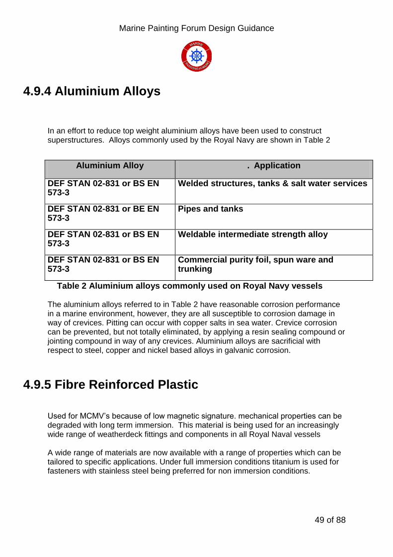
In an effort to reduce top weight aluminium alloys have been used to construct superstructures. Alloys commonly used by the Royal Navy are shown in Table 2
Aluminium Alloy . Application
DEF STAN 02-831 or BS EN 573-3
Welded structures, tanks & salt water services
DEF STAN 02-831 or BE EN 573-3
Pipes and tanks
DEF STAN 02-831 or BS EN 573-3
Weldable intermediate strength alloy
DEF STAN 02-831 or BS EN 573-3
Commercial purity foil, spun ware and trunking
Table 2 Aluminium alloys commonly used on Royal Navy vessels
The aluminium alloys referred to in Table 2 have reasonable corrosion performance in a marine environment, however, they are all susceptible to corrosion damage in way of crevices. Pitting can occur with copper salts in sea water. Crevice corrosion can be prevented, but not totally eliminated, by applying a resin sealing compound or jointing compound in way of any crevices. Aluminium alloys are sacrificial with respect to steel, copper and nickel based alloys in galvanic corrosion.
4.9.5 Fibre Reinforced Plastic
Used for MCMV’s because of low magnetic signature. mechanical properties can be degraded with long term immersion. This material is being used for an increasingly wide range of weatherdeck fittings and components in all Royal Naval vessels A wide range of materials are now available with a range of properties which can be tailored to specific applications. Under full immersion conditions titanium is used for fasteners with stainless steel being preferred for non immersion conditions.

Marine Painting Forum Design Guidance
50 of 88
5 Surface Preparation Prior to Preservation
The objective of surface preparation is to remove any substance detrimental to the performance of a paint from the surface such as millscale, rust, soluble salts, oil and grease and to provide a suitable surface profile to allow paint adhesion.
The removal of these contaminants and profile creation is imperative to create a sound surface to which a paint can both mechanically and chemically bond thus creating a homogeneous coating that will resist corrosion for a period of time as specified by paint manufacturer.
If UHP (ultra high pressure) water is to be used for paint removal it must be noted that this does not provide a surface profile. This system must be used with great care due to the damage that can be caused to both substrate and human tissue.
5.1 General Techniques To obtain the optimum performance from a paint system, the surface must be correctly prepared. Before the primer is applied, the surface should have a specified profile and cleanliness standard i.e. be free from contamination and corrosion. Discontinuities that occur in the material which disrupt the surface should also be smoothed out so that an even surface is obtained. Process defects must also be repaired or removed before the paint system can be applied. Normal methods used for removing surface defects include the use of needle guns and grinding discs. Typical process defects and the action required prior to preservation are shown in Figures 5.5 to 5.12. Technical information from paint suppliers will describe the correct surface preparation requirements.
Repair of damaged coating systems, where the substrate has become exposed and subsequently corroded, requires that the damaged area should be firstly mechanically abraded to clean the area of the exposed substrate, to manufacturers specification, for application of the new system. To ensure the optimum performance of the repair all corrosion must be removed.
On surfaces where it is difficult to obtain the specified thickness of coating or where the system needs reinforcement, it is necessary to apply a stripe coat to the area by brush before and between spray coats. This is needed to provide enhanced protection for the material substrate. Examples of the areas where stripe coatings are required on weather decks and other areas are shown in Figures 5.9-5.18. Each Figure shows a different aspect where stripe coating is essential to reinforce the paint system against mechanical damage which can lead to corrosion setting in.
Marine Painting Forum Design Guidance
51 of 88
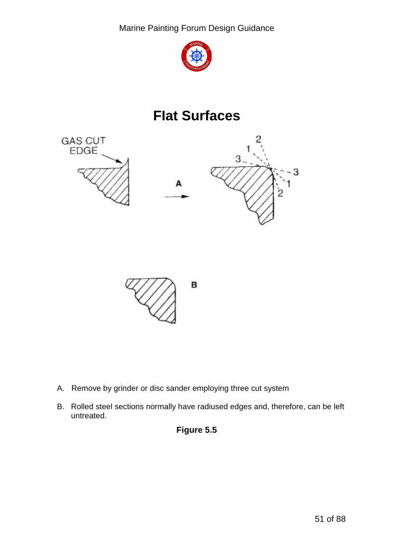
FIat Surfaces
A. Remove by grinder or disc sander employing three cut system B. Rolled steel sections normally have radiused edges and, therefore, can be left
untreated.
Figure 5.5

Marine Painting Forum Design Guidance
52 of 88
Gas Cut Surfaces
Sharp edges produced by gas cutting to be treated in accordance with “Flat Surfaces” procedure.
Figure 5.6

Marine Painting Forum Design Guidance
53 of 88
Weld Spatter
A. Remove spatter with grinder or chipping hammer before grit blasting
B. For spatter not readily removed, remove using grinder.
Figure 5.7

Marine Painting Forum Design Guidance
54 of 88
Weld Beads
Sharp Profile peaks to be smoothed using grinder
Figure 5.8

Marine Painting Forum Design Guidance
55 of 88
Laminations
Remove using grinder.
Figure 5.9
Marine Painting Forum Design Guidance
56 of 88
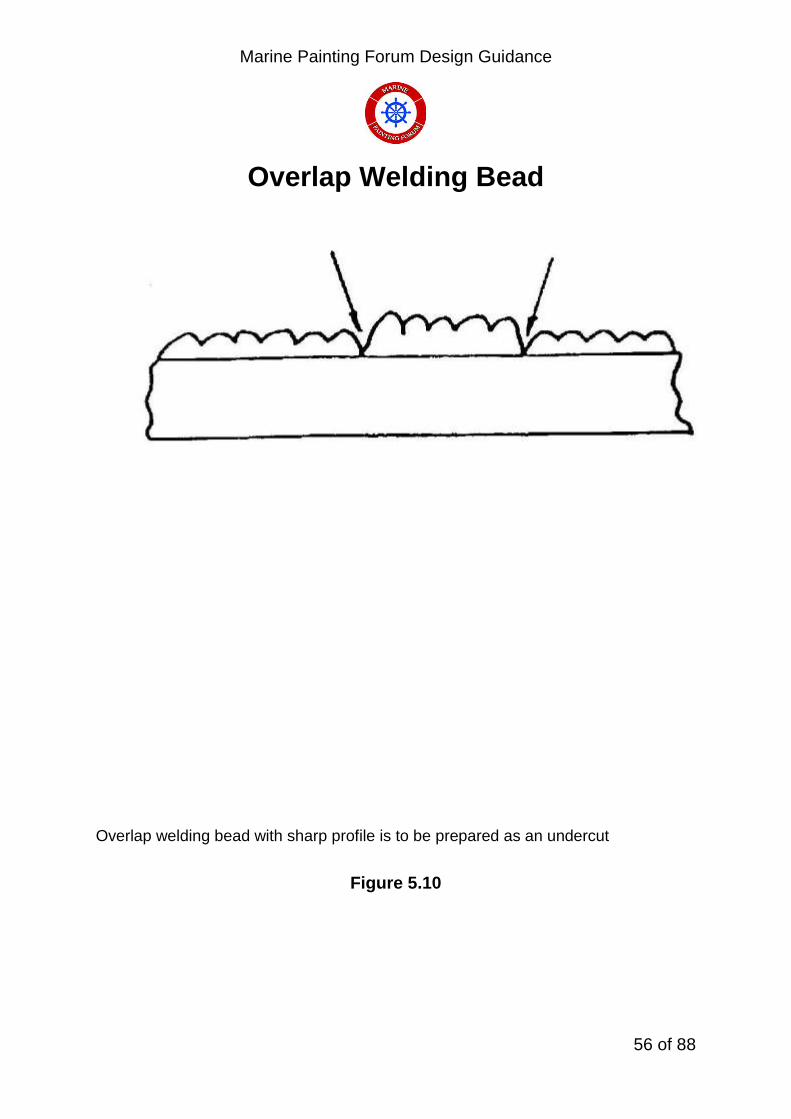
Overlap Welding Bead
Overlap welding bead with sharp profile is to be prepared as an undercut
Figure 5.10
Marine Painting Forum Design Guidance
57 of 88
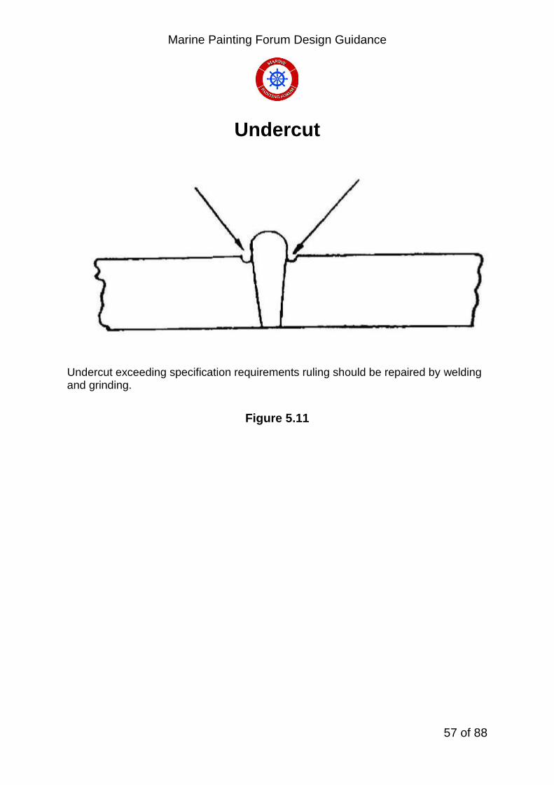
Undercut
Undercut exceeding specification requirements ruling should be repaired by welding and grinding.
Figure 5.11

Marine Painting Forum Design Guidance
58 of 88
Weld Blowhole
Weld and grind before blasting. Those found after blasting: 1. Weld and grid at blasting stage. 2. Weld and grind at holding primer stage.
Filling of blowholes with epoxy filler is not to be recommended. Weld to be stripe coated
Figure 5.12

Marine Painting Forum Design Guidance
59 of 88
Frame to Beam Connection
<<<< Indicates areas to be stripe coated Note – Reverse face of flange is also to be stripe coated.
Figure 5.13

Marine Painting Forum Design Guidance
60 of 88
Ladder on Bulkhead
<<<< Indicates areas to be stripe coated
Figure 5.14

Marine Painting Forum Design Guidance
61 of 88
Deckhead
<<<< Indicates areas to be stripe coated Note – Reverse face of flange is also to be stripe coated.
Figure 5.15

Marine Painting Forum Design Guidance
62 of 88
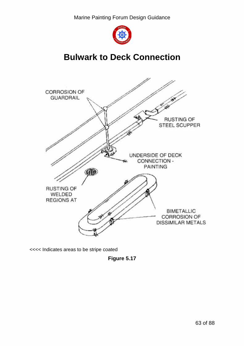
Bulwark to Deck Connection
<<<< Indicates areas to be stripe coated
Figure 5.16
Marine Painting Forum Design Guidance
63 of 88
Bulwark to Deck Connection
<<<< Indicates areas to be stripe coated
Figure 5.17
Marine Painting Forum Design Guidance
64 of 88
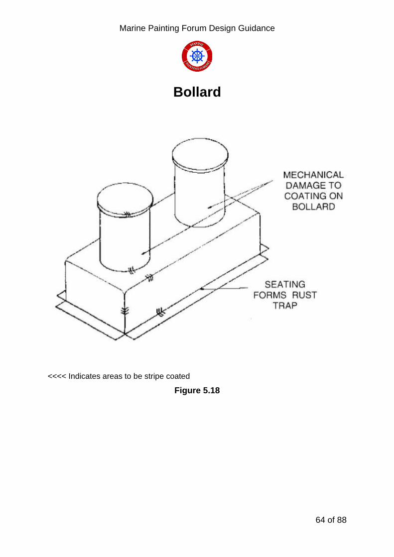
Bollard
<<<< Indicates areas to be stripe coated
Figure 5.18

Marine Painting Forum Design Guidance
65 of 88
Tripping Bracket
<<<< Indicates areas to be stripe coated
Figure 5.19

Marine Painting Forum Design Guidance
66 of 88
Stanchion
<<<< Indicates areas to be stripe coated
Figure 5.20

Marine Painting Forum Design Guidance
67 of 88
Stanchion
<<<< Indicates areas to be stripe coated
Figure 5.21

Marine Painting Forum Design Guidance
68 of 88
Ladder onto Structure in a Tank
<<<< Indicates areas to be stripe coated
Figure 5.22
Marine Painting Forum Design Guidance
69 of 88
5.2 Standards
Before the application of a preservation system, steel is to be abrasively blast cleaned to a minimum quality standard Sa 2½ to British Standard BS7079 Part Al-2009 “Preparation of Steel Substrates before Application of Paints and related products”. The equivalent specification noted in the British Standard is:
ISO 8501 -1 - 2007
This standard contains transparencies which can be compared directly with the abrasive blasted surfaces. All users of these standards must be familiar with the surface finish requirements. It should be noted that steel surfaces must not be burnished prior to painting as this will give rise to poor adhesion. Although Sa 2½ is commonly used as a standard, it must be emphasised that this defines cleanliness only and does not define surface profile.
Sa 2½ Specification:
Very thorough blast cleaning” requires the following: ‘When viewed without magnification the surface shall be free from visible oil, grease and dirt and from mill scale, rust, paint coatings and foreign matter. Any remaining traces of contamination shall show as only slight stains in the form of spots or stripes. Finally the surface is cleaned with a vacuum cleaner, clean dry compressed air or a clean brush”.

Marine Painting Forum Design Guidance
70 of 88
5.3 Containment To ensure that an area can be abrasive blasted and then coated within manufacturer’s specification, the area must be contained to exclude the effects of the weather whilst ensuring that blast media or paint overspray does not contaminate the external environment. The containment must also ensure that suitable environmental conditions can be created (micro climate) within the area to be preserved. This will entail the use of de-humidification/humidification units coupled together with space heaters. Containment also eases the collection of arisings and spent blast media during cleaning operations prior to coating application. See Figure 5.1
Tented Flight deck of a Royal Navy Vessel
Figure 5.1

Marine Painting Forum Design Guidance
71 of 88
5.3.1. Scaffolding Scaffolding must be erected in a manner that gives easy access with minimum contact points to the surface to be preserved while also providing a safe working area to the abrasive blasters and painters. This is of particular importance where operators are working on side curvature in way of both bow and stern areas where significant areas of flair are encountered.
5.3.2. Tenting
Tent material must be of a robust yet lightweight nature and meet the following criteria:
Be able to withstand an indirect blast of abrasive material without any detrimental effect.
Be able to be manhandled over scaffolding.
Be able to form a weathertight environment.
Be fire resistant.
Be able to be connected to ships structure.
For examples see Figure 5.2 and 5.3

Marine Painting Forum Design Guidance
72 of 88
Figure 5.2
Figure 5.3

Marine Painting Forum Design Guidance
73 of 88
5.4 Blast Media
There are numerous forms of blasting media commercially available for various substrates. These have been split into three groups; Expendable, Recyclable and Specialist. A guide to the numerous general use types can be seen in Figures 5.4 and 5.5. When selecting the proffered blasting media, it is imperative that the specified profile is taken into account e.g. if a surface roughness of 75 µm Rz (surface roughness) is required then steel shot cannot be used
. Figure 5.4
Figure 5.5
Specialist Abrasive Blast Media
Plastic Grains
Crushed Walnut Shell
Glass Grit
Glass Bead
Marine Painting Forum Design Guidance
74 of 88
6. Application of Different Preservation Systems for Corrosion Control
6.1 General For Royal Naval vessels, preservation systems are to be carefully selected from the list of MOD approved materials held by DES SESea-MT5. All preservation systems are to be applied strictly in accordance with the instructions contained in the paint manufacturer’s technical data sheets and specifications.
For general shipbuilding, the selection of preservation systems will be dictated by the ship owner in consultation with selected paint manufacturer. All preservation systems are to be applied strictly in accordance with the instructions contained in the paint manufacturer’s technical data sheets and specifications.
For all new build vessels (with the exception of submarines), corrosion prevention of seawater ballast tanks is currently prescribed by SOLAS regulation II-1/3-2, making it mandatory for all dedicated seawater ballast tanks to have a corrosion prevention system with a minimum life expectancy of at least 15 years. It should be noted that this regulation is being considered for applicability to other regions of the ship.
6.2 Requirements for Painting
As a pre-requisite, all paint and coating activities require to be fully planned and incorporated into the build cycle of any contract be it new build or refurbishment. Without proper planning, the potential exists for “rushed” application leading to early system failure which can result in coatings having to be removed and re-applied correctly. The costs involved with this course of action are prohibitive as is the damage to the fabricators reputation therefore the maxim of “Plan the work and then work the plan” is of the highest importance. It is not intended in this guidance note to define all the conditions necessary for the successful application of paint coatings. However, it is essential that the conditions specified in the manufacturer’s specification and/or technical data sheets are observed. Data sheets will specify the surface preparation required for the successful application of a particular paint coating and will also specify the environmental conditions required for successful application and curing. The requirements for curing paint coatings are easily overlooked but are, of course, critical to the performance of the coating system. The curing of potable water tank

Marine Painting Forum Design Guidance
75 of 88
coatings is a case in point; if the coatings are incorrectly applied at a high wet film thickness or allowed to cure in low temperature conditions, the coatings can retain solvent which will contaminate the potable water when the tanks are filled.
The plan must take into account both pot life for applications and curing times. Other trades have to be consulted to ensure that planned work takes painting activities into account to ensure that no nugatory work is undertaken.
Planning must also take into account the rate that paint is applied to ensure that unrealistic targets are not set leading to downtime for other trades.
The component coatings of a paint system should all be sourced from the same manufacturer. Indeed, some coatings systems, e.g. those for flight decks and for potable water tanks, are qualified as systems. For Royal Navy vessels guidance on approved paint coatings and paint systems can be found in Warpaint.
The paint manufacturer’s recommended method of coating application can be found on their respective technical data sheets. High solids, low solvent coatings, should be applied by airless spray but for small areas generally brush or roller application will be possible. It should be noted that the use of a brush or roller will require additional coats to meet the specified film thickness.
6.3 Paint Application
All paints must be applied in specified controlled environmental conditions to meet the requirements of the paint manufacturer’s specification. No paint shall be applied if the relative humidity exceeds 85%, and the substrate temperature shall be at least 3oC above the calculated dew point, or as per manufacturers’ recommendations on their published data sheets. Due note is to be taken of the time of year when the paint is to be applied, e.g. in proposing summer and/or winter drying paints. The degree of cleaning prior to application shall be in accordance with the manufacturer’s recommendations, and to the satisfaction of the agreed nominated authority and the paint manufacturers’ representative. Areas not effectively covered by the spray process shall be coated by brush or roller to achieve the specified film thickness. All plate edges, welds on weatherdecks, welds in tanks, draught marks, welds and areas of turbulent flow underwater are to be stripe coated ensuring the specified paint film thickness is achieved.

Marine Painting Forum Design Guidance
76 of 88
No paints of different colours or types shall be mixed, and to avoid contamination, all paint lines shall be thoroughly cleaned through prior to application of a different paint type or colour. Dedicated paint lines will help reduce the amount of solvent required for cleaning. Due care and attention to be taken when mixing paints. All multiple pack systems are to be mixed exactly to the manufacturer’s instructions to ensure that system is as defined. When a final paint coat is applied over a previous coat that has been exposed to the marine atmosphere for a significant period of time, then the previous paint coat is to be fresh water washed to remove salts, prior to applying the final coat. In the case of external systems, this is to be high pressure (2500 psi) fresh water washed. This is to ensure good adhesion of the final coat to produce a high quality paint system. 6.3.1 Paint Film Thickness after Application and Cure. If, by measuring on dry paint film, the total thickness of the applied paint coat on a part of the surface is found below the nominal thickness, this part shall be touched-up until the required thickness is achieved to the satisfaction of nominated Quality Control (QC) authority. Film thickness shall be as per the recommended thickness, as specified by paint manufacturer and or customer. Film thickness is dry film thickness (DFT) per coat.
6.4 Occupational Hygiene Considerations
Paints specified for naval use will all have been assessed by the Institute of Naval Medicine and published guidelines for their use and for the protection required to be worn by operators must be scrupulously observed. Manufacturer’s health and safety information is now presented in the CHIP (Chemicals, Hazard Information, and Packaging) format which contains a wider range of information than was previously required.
If a re-fit or refurbishment of a vessel built prior to 1995 is being considered, it is imperative that a record of previous coatings be obtained by either consulting ship’s records or, if records are unobtainable, by chemical analysis. This course of action is required to determine if products such as zinc

Marine Painting Forum Design Guidance
77 of 88
chromate primer have been previously applied. As zinc chromate has now been declared a carcinogen, special measures must be taken for both removal and disposal. Consult local Health and Safety Executive for advice PRIOR to starting any work in the contaminated area.
6.5 Type of Paint Coating
There are numerous types of coatings specified for Royal Naval (see Warpaint) and commercial use, these range from high solid low solvents, water based epoxies as well as standard two-pack epoxy coatings. The latter comes in a variety of forms depending upon end usage and can be expected to provide superior and durable protection if correctly applied. They are, however, subject to chalking in ultra violet light (natural sunlight) and are, therefore, not generally used as finishing coats for exterior use; an exception is made in the case of flight and weather deck finishes.
The coatings specified for Royal Naval use are regularly reviewed to keep pace with ever changing National and International Legislation as well as Environmental requirements. Additionally, many familiar materials, e.g. zinc chromate, are now subject to restriction or require additional precautions in their use. Moreover, the paint manufacturers require to handle ‘hazardous’ compounds in greater bulk and concentration than will be found in the manufactured paint; this alone has encouraged reformulation.
N.B. For Royal Naval vessels, it has so far proved to be impossible to develop the ‘ideal’ paint coating. If difficulty is experienced in selecting a coating suitable for Royal Naval application, advice should be sought from [email protected] telephone 0306 793 5047.
IMO MSC.215(82) Performance Standard for Protective Coatings - a standard designed to achieve a target coating lifetime of 15 years in dedicated seawater ballast tanks and double side-skin spaces of bulk carriers.
At newbuilding, on vessels of not less than 500GT, all coatings used in seawater ballast tanks and the double-side skin spaces in bulk carriers of >150m length, including the shop primer if retained, must now comply with PSPC regulations. To comply, all coatings must have a ‘Type Approval Certificate’ (TAC) which means that the product has demonstrated the expected performance, the quality of the

Marine Painting Forum Design Guidance
78 of 88
supplied material is assured and that the supply location has met the requirements of the body insuing the TAC. The IMO PSPC is applicable to vessels where: · the building contract was placed on or after 1st July 2008, or · if no contract, the keel of which was laid on or after 1st January 2009, or · the delivery is on or after 1st July 2012.
6.6 Maintenance Painting Problems frequently arise when repairs and modifications require to be made to ships in operation. Consequently, weather tolerant rapidly curing primers are being introduced for the repair situation and this should lead to an improvement in the standard of preservation of repairs and modifications. This does, however, highlight some of the problems associated with producing the ‘perfect’ paint; although these products cure rapidly and it is, in some cases, possible to apply 3 coats of primer in a 24 hour period, their overcoating interval is short which means that they are not so practical for use in the build or refit situation when it might be necessary to apply the primer some time before the subsequent coats are applied. Prior to application of any ‘quick’ cure primer in operational use, permission must be sought from ship owner/operator.
6.7 Powder Coatings
Electrostatically applied, heat cured, powder coatings provide superior and durable finishes for component parts, particularly when combined with an aluminium sprayed substrate. They also contribute to VOC reduction because they contain no solvents. Metal spraying of components for use within the ship is only justified for such items installed in hostile environments e.g. machinery spaces and wet compartments. There is a limit to the size of component which can be powder coated as current technology requires the powder coated component to be either placed in an oven to be cured or to pass through an infra-red curing facility.
Marine Painting Forum Design Guidance
79 of 88
6.8 Summary
All paint coatings have their limitations. The specifier and the applicator must be aware of these limitations and choose and apply the paint scheme which is most appropriate to the intended service conditions and to the conditions which can be achieved during application and curing. Painting is expensive; the total cost of a paint job is, typically, some 10 times the cost of the paint -and paint coatings must be used correctly to properly preserve the ship and its components and to reduce Through Life Costs.
7. Quality Control Considerations To ensure that coated surfaces achieve the lifetime requirements as laid down in specifications, it is imperative that Quality standards are defined prior to purchase of coatings and beginning of fabrication. These standards are to be communicated to Owners, coating supplier and fabricators with a full, auditable, filing system in place prior to contract start date. Without specifying these pre-requisites, the way will be left open for misinterpretation and potential early failure of the system. It is proposed that the following paragraph is mandatory: Inspection will be carried out by Shipbuilder’s Quality Control department (QC) and the paint manufacturer’s dedicated representative at each agreed working stage e.g. steel surface preparation, environmental conditions prior to coating, recording of dry film thicknesses (DFT’s) on application of each coat etc. This acceptance will be in the form of both physical inspections of critical areas and by means of audit acceptance, from QC data, in other areas. At any stage, the Owner’s Overseer (OO) may be present to witness the inspection. Work shall not continue until all parties have approved each agreed working stage. All parties, prior to application shall agree that surface preparation standards have been achieved. All inspection records shall be documented and recorded.

Marine Painting Forum Design Guidance
80 of 88
7.2 Measurement of Dry Film Thickness The aim of the Note is to provide a standardised method for the measurement of the Dry Film Thickness data recorded for paint films of HM Ships and Submarines. The Note has been produced by the DFT Measurement sub-committee of the Marine Painting Forum and it is our view that the two most important parameters in DFT measurement, namely common sense and paint manufacturers’ experience and opinions cannot be over emphasised.
7.2.1 Background The problem of DFT measurement and the use to which the data is put is far from being new and has been an occupational hazard for many years. It has occupied the thoughts of many and yet there is no internationally recognised Standard which has found universal acceptance for recording or using DFT data.
7.2.2 Current DFT Measurement Standards There are currently 3 standards which may be employed: Swedish Standard SS 18 41 60 “Paints and varnishes – The Determination of thickness of a film on a metal substrate – Magnetic flux and eddy current methods” Steel Structures Painting Council (SSPC) Passageway-2 “Paint application specification No 2. Measurement of dry paint thicknesses with magnetic gauges”. BS3900 Part C5 1997 (ISO 2808 1997) “Determination of film thickness”. Unfortunately the least useful of these documents is BS 3900 as in reality it states nothing more than follow manufacturer’s instructions albeit for a wide variety of measuring devices. Both Swedish and American standards require multi-point sampling around a single point followed by averaging of that data. When the whole painted structure has been examined the averages obtained above are further averaged to derive the DFT of the work piece. In practice this means taking between 135 and 166 individual readings per 100m2 of painted surface depending on which standard is followed. It is also important to note that both Standards allow for local film thicknesses to be below the nominal value provided the mean film thickness is at least equal to the

Marine Painting Forum Design Guidance
81 of 88
nominal film thickness. The American standard allows for local DFT’s to be within 80% of the nominal value whilst the Swedish standard states readings should be within 85% of the nominal DFT. In reality this means that for a nominal 100µm DFT values as low as 80µm would be accepted provided the mean average over the job was at, or above, 100µm. Unfortunately neither Standard appears to limit the number of low readings permissible although 20% seems to be an acceptable paint industry norm. In simple terms this means that at least 80-85% of all readings should be at, or above, the Specified minimum DFT. The remaining 15% of readings should be within 80% of the Specified minimum DFT. No single reading should be below this value. Similarly, both Standards require an allowance to be made for the surface profile which is currently not required within BR 3939. The working group felt that in all probability this was not a common practice in the UK in general. However, some of the better commercial applicators may make an allowance for these effects. In terms of where DFT’s should be measured the Standards and other documents are also reasonably specific regarding areas and paint thickness that should be avoided. Typically areas less than 15mm from an edge, areas less than 30mm from shoulders, and thin film paints on a blasted surface (i.e DFT’s < 75µm) should all be avoided with magnetic flux probes without first undertaking some form of special calibration. The Swedish Standard also mentions reading errors on concave surfaces (too low) and on convex surfaces (too high) if the gauge is calibrated on a flat surface. Overall therefore, it is clear that the measurement of DFT has been, and still is, a minefield into which we stumble at our peril and the one thing that we need but is not spelt out in any Standard is to have a pragmatic approach and a large measure of common sense. Clearly, the surface preparation and painting are an art not strictly controlled laboratory science and even when painting enters the laboratory it is still not possible to produce a perfectly uniform dry film. For ballast tank measurements requirements are specified in SOLAS PSPC regulations.
7.2.3 Calibration. Zero the instrument on a steel surface having similar profile to that of the work piece. For best results the instrument should be calibrated on the structure to be measured. Where this is not possible a standard flat panel approximately 75x75x5mm blasted with the same media used on the job should be used. For mechanically (i.e.

Marine Painting Forum Design Guidance
82 of 88
needlegun descaled, wire brushed, grinder etc.) or chemically stripped surfaces calibration should be made on clean, flat steel. (NOTE A prepared test panel will hold its finish for some weeks if stored with silica gel crystals in a sealed plastic bag and need not therefore be re-prepared for every calibration) Calibrate the instrument following manufacturer’s recommendations using calibrated plastic shims with a thickness above and below the anticipated thickness to be measured. The calibration shims shall be in good condition, free from wear and be calibrated to a traceable Standard. Probes shall be examined for damage or wear at regular intervals and be replaced as necessary. Where possible calibration should be made at the work place. However, it is realised that in some situations this may not be practical (e.g. double bottom tanks) in which case calibration should be made under environmental conditions as close to those of the work place as possible. Once instrument calibration is complete DFT measurements can be made.
7.2.4 Rate of DFT Measurement. On flat surfaces readings should be taken at a rate of 1 per m2 but should NOT be made within 15mm of edges, welds, paint runs or substrate defects (e.g. pitted areas etc.). This distance should be increased to 30mm on flanges, shoulders and other areas of large changes in cross section of the substrate. On ‘I’ beams (webbing and flange) one reading per 50cm but taking note of the comments made above regarding distances from edge etc. On pipe work one reading per 50cm, but taking note of the comments above regarding flanges etc, ensuring that all areas of the pipe are adequately represented. (NOTE. On pipework unless the instrument can be re-calibrated on a test panel having the same radius as the pipe under examination it may be expected that the actual DFT may be lower than the value obtained. However, this variation cannot as yet be quantified and therefore the readings obtained should be used). Values that are obviously too low or too high and CANNOT be reproduced should be rejected. Low or high values should NOT be “chased” to determine the extent of their range at this stage as this will distort the mean value obtained. It is recommended that on blast cleaned surfaces no DFT measurements are made on paint films below 75µm as the errors induced by the effect of variation in surface profile are too great.

Marine Painting Forum Design Guidance
83 of 88
7.2.5 Using DFT Data Using this method the recorded DFT is the average thickness of paint over the peaks in the area directly beneath the probe. When the examination is complete these values are to be added together and divide by the number of readings to produce an average DFT. The AVERAGE value of the DFT measurements should not be below the minimum or target value specified by the paint manufacturer. At least 85% of all readings should be at, or above, the specified minimum DFT. The remaining 15% of readings shall not be less than 80% of the specified minimum DFT. No single value shall be below this thickness. Where practical paint over thickness should be kept to within 30% of the specified target thickness. However, it is recognised that overlap areas and complex structures can produce localised high spots which exceed this target. In these cases values of 50% or more may be obtained. The acceptability of such a situation is largely dependant on the paint system and the areas to which it is being applied. In such situations the values should be reported to the paint manufacturer and his advice obtained. Similarly, guidance on health and safety implications due to over application of paint should be sought from interested parties. Once this initial survey has been completed any unacceptably low or high areas identified can be examined in greater detail and the appropriate action taken.

Marine Painting Forum Design Guidance
84 of 88
8. Protection During Build / Re-fit
On completion of initial painting, areas such as weatherdecks and internal deck and bulkheads require to have protective media fitted to avoid damage caused by workforce traffic through these areas. There are various barrier methods that can be applied to minimize such damage with the most common being peelable coating or physical boarding. All protective media must be suitably fire retarded and approved for use in the shipbuilding industry.
1. Peelable coating – a sacrificial coating that is applied to finished paint surface that, on completion of build is removed leaving a clean substrate for delivery. While this type of product has benefits for commercial shipping it is not suited to Royal Naval vessels. This is due to the protracted build time and the amount of equipment fitted to passageway bulkheads making it very difficult to remove.
2. Board type products – Very effective if applied at the correct stage of build. This product can be re-used if undamaged giving greater cost saving over the use of peelable coatings. See Figure 8.1
3. Rubber sheeting – Mainly used on weatherdecks. This product, if applied on top of a breathable membrane, gives a non-slip walking surface that protects the heavily aggregated paint from both wear and mechanical impact damage. This product is also re-useable. See Figure 8.2.
In addition to protecting paint surfaces, physical barrier protection can be applied to sundry items of equipment fitted throughout the ship. The cost of fitting this type protection is minimal when compared to mechanical damage incurred during the build cycle. See Figure 8.3 and Figure 8.4.

Marine Painting Forum Design Guidance
85 of 88
Figure 8.1 Internal Deck Protection
Figure 8.2 Weatherdeck Protection

Marine Painting Forum Design Guidance
86 of 88
Figure 8.3 AEL Protection Box as Delivered
Figure 8.4 AEL Protection Box as Fitted

Marine Painting Forum Design Guidance
87 of 88
9. Related Documents
BR 3013 (1&2) Admiralty Pipework Standards
BS 3076: 1989: Specification for nickel and nickel alloys: bar.
BS EN ISO 3506-1 Mechanical Properties of corrosion-resistant stainless steel fasteners
BS7079:2009 General Introduction to Standards for Preparation of Steel Substrates before Application of Paints and Related Products.
BS EN ISO 8501-1:2007 General Introduction to Standards for Preparation of Steel Substrates before Application of Paints and Related Products.
DEF STAN 02-149 Access Policy in Surface Ships
DEF STAN 02-310 Requirements for the Manufacture of Commercially Pure Titanium Seamless Tubes, Type A – Heat Exchanger, Type B – General Purpose
DEF STAN 02-747 Nickel Aluminium Bronze Castings and Ingots
BR 3939 Hull Preservation Process
DEF STAN 02-779 Requirements for 90/10 Copper Nickel Alloy Material
DEF STAN 02-780 Requirements for 70/30 Copper Nickel Alloy Material
DEF STAN 02-833 Requirements for Nickel Aluminium Bronze
DEF STAN 02-834 Requirements for Aluminium Silicone Bronze
DEF STAN 02-862 Fasteners for Naval Use
Warpaint – DESSESea-MT Guidance Document of Approved Coatings for In-Service and New-Build Royal Navy Vessels.
Marine Painting Forum Design Guidance
88 of 88
SSCI No. 5/93 Restriction in the Use of Cadmium
Swedish Standard SS18 41 60 “Paints and Varnishes – Determination of Thickness of a Dry Film on a Metal Substrate – Magnetic Flux and Eddy Current Methods.”
Steel Structures Painting Council SSPC Passageway-2 “Paint Application Specification No 2. Measurement of Dry Paint Thicknesses with Magnetic Gauges.”
BS3900 Part C5 1992 (ISO 2808 1991) “Determination of Film Thickness.”
Dry Film Thickness Measurement – “A Blasted Problem.” J. Nugent, Technical Director, W&J Leigh Ltd.
Problems associated with paint thickness measurement. M. McKenzie, PRA Symposium on preparation and painting of structural steel. 11-12 April 1984.
Measuring Dry Film Thickness. L Igetoft,. Euro. Coat. J. 9. 1992. 554