
GTN Xi Series
65
GTN Xi Series Software v20.20 Upgrade Supplement This supplement contains revised pages from GTN Xi Series Pilot’s Guide, P/N 190-02327-03, Rev. D. These pages contain new information regarding the features of software v20.20. Black bars adjacent to revised information correspond to changes described in the revision summary table. Features and screen images are dependent upon the installed software version and its configuration. For more information regarding feature availability, refer to the pilot’s guide. An electronic version of the pilot’s guide is available for viewing on your computer or portable device. Go to garmin.com/manuals .
Transcript of GTN Xi Series

GTN Xi Series
Software v20.20Upgrade Supplement
This supplement contains revised pages from GTN Xi Series Pilot’s Guide, P/N 190-02327-03, Rev. D. These pages contain new information regarding the features of software v20.20.
Black bars adjacent to revised information correspond to changes described in the revision summary table.
Features and screen images are dependent upon the installed software version and its configuration. For more information regarding feature availability, refer to the pilot’s guide.
An electronic version of the pilot’s guide is available for viewing on your computer or portable device. Go to garmin.com/manuals.
COPYRIGHT & TRADEMARKS
© 2019 - 2021 Garmin International, Inc., or its subsidiaries. All rights reserved.
Except as expressly provided herein, no part of this manual may be reproduced, copied, transmitted, disseminated, downloaded or stored in any storage medium, for any purpose without the express prior written consent of Garmin. Garmin hereby grants permission to download a single copy of this manual and of any revision to this manual onto a hard drive or other electronic storage medium to be viewed and to print one copy of this manual or of any revision hereto, provided that such electronic or printed copy of this manual or revision must contain the complete text of this copyright notice and provided further that any unauthorized commercial distribution of this manual or any revision hereto is strictly prohibited.
Garmin®, FliteCharts®, and SafeTaxi® are registered trademarks of Garmin International or its subsidiaries. Connext™, Garmin Pilot™, Garmin SVT™, G3X Touch™, Smart Airspace™, Smart Glide™, and Telligence™ are trademarks of Garmin International or its subsidiaries. These trademarks may not be used without the express permission of Garmin.
The Bluetooth® word mark and logos are registered trademarks owned by Bluetooth SIG, Inc. and any use of such marks by Garmin is under license. Other trademarks and trade names are those of their respective owners.
Iridium® is a registered trademark of Iridium Communications, Inc. All rights reserved.
Mac®, Macintosh®, and macOS® are registered trademarks of Apple Inc.
NavData® is a registered trademark of Jeppesen, Inc.
© 2021 SD® is a registered trademark of SD-3C, LLC. All rights reserved.
© 2021 SiriusXM Satellite Radio, Sirius, SXM, and all related marks and logos are trademarks of SiriusXM Radio Inc. All other marks and logos are property of their respective owners. All rights reserved.
SkyWatch® and Stormscope® are registered trademarks of L-3 Communications.
The term Wi-Fi® is a registered trademark of the Wi-Fi Alliance®.
All other marks and logos are property of their respective owners. All rights reserved.
INFORMATION & SUPPORT
For information regarding the Aviation Limited Warranty, refer to Garmin’s website.
For aviation product support, visit flyGarmin.com.
Overview
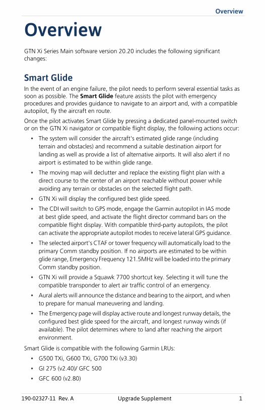
OverviewGTN Xi Series Main software version 20.20 includes the following significant changes:
Smart GlideIn the event of an engine failure, the pilot needs to perform several essential tasks as soon as possible. The Smart Glide feature assists the pilot with emergency procedures and provides guidance to navigate to an airport and, with a compatible autopilot, fly the aircraft en route.
Once the pilot activates Smart Glide by pressing a dedicated panel-mounted switch or on the GTN Xi navigator or compatible flight display, the following actions occur:
• The system will consider the aircraft's estimated glide range (including terrain and obstacles) and recommend a suitable destination airport for landing as well as provide a list of alternative airports. It will also alert if no airport is estimated to be within glide range.
• The moving map will declutter and replace the existing flight plan with a direct course to the center of an airport reachable without power while avoiding any terrain or obstacles on the selected flight path.
• GTN Xi will display the configured best glide speed.
• The CDI will switch to GPS mode, engage the Garmin autopilot in IAS mode at best glide speed, and activate the flight director command bars on the compatible flight display. With compatible third-party autopilots, the pilot can activate the appropriate autopilot modes to receive lateral GPS guidance.
• The selected airport's CTAF or tower frequency will automatically load to the primary Comm standby position. If no airports are estimated to be within glide range, Emergency Frequency 121.5MHz will be loaded into the primary Comm standby position.
• GTN Xi will provide a Squawk 7700 shortcut key. Selecting it will tune the compatible transponder to alert air traffic control of an emergency.
• Aural alerts will announce the distance and bearing to the airport, and when to prepare for manual maneuvering and landing.
• The Emergency page will display active route and longest runway details, the configured best glide speed for the aircraft, and longest runway winds (if available). The pilot determines where to land after reaching the airport environment.
Smart Glide is compatible with the following Garmin LRUs:
• G500 TXi, G600 TXi, G700 TXi (v3.30)
• GI 275 (v2.40)/ GFC 500
• GFC 600 (v2.80)
190-02327-11 Rev. A Upgrade Supplement 1
Overview
Option to bypass Instrument Self-test pageDuring initialization, the Instrument Self-test page would previously appear. GTN Xi can now be configured to bypass the Instrument Self-test page. This feature is for installations that do not have instruments requiring a self-test.
Remote Database ConfirmationA new feature on the start-up page of the primary GTN Xi will display current database information for compatible configured LRUs in the cockpit. In addition, any out-of-date databases will appear as such on GTN Xi. This feature reduces pilot workload for installations with multiple GTN Xi and/or G500(H)/G600/G700 TXi (v.3.30) units.
New label for "ADS-B Out" keyThe Transponder menu page would previously show an "Enable ES" key used to command the transponder to send ADS-B out data. The new “ADS-B Out” label is more suitable for the key's function.
2 Upgrade Supplement 190-02327-11 Rev. A
Change List
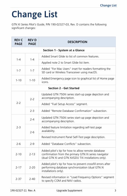
Change ListGTN Xi Series Pilot’s Guide, P/N 190-02327-03, Rev. D contains the following significant changes:
REV C PAGE
REV D PAGE DESCRIPTION
Section 1 - System at a Glance
1-4 1-4Added Smart Glide to list of common features.
Applied note 2 to Smart Glide list item.
1-7 1-7Added "For Mac Users" inset for readers formatting the SD card or Wireless Transceiver using macOS.
1-10 1-10Added Emergency page icon to graphical list of Home page icons.
Section 2 - Get Started
2-22-2
Updated GTN 750Xi series start-up page depiction and accompanying description.
Added “Fuel Setup Access” segment.
2-3 Added “Remote Database Confirmation” subsection.
2-3
2-4Updated GTN 750Xi series start-up page depiction and accompanying description.
2-6
Added feature limitation regarding self-test page availability.
Revised Instrument Panel Self-Test page description.
2-6 2-9 Added “Database Conflicts” subsection.
2-10 2-13Added pilot's tip for how to allow remote database confirmation from the primary GTN Xi series navigator (dual GTN Xi and GTN Xi/GDU TXi installations only).
2-17 2-20Added pilot's tip for how to prevent crossfill errors after performing database synchronization (dual GTN Xi installations only).
2-37 2-40Revised information in “Load Frequency Options” segment to specify COM and NAV radios.
190-02327-11 Rev. A Upgrade Supplement 3
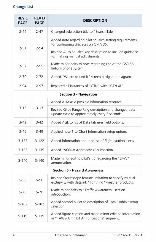
Change List
2-44 2-47 Changed subsection title to “Search Tabs.”
2-51 2-54
Added note regarding pilot squelch setting requirements for configuring discretes on GMA 35.
Revised Auto Squelch key description to include guidance for making manual adjustments.
2-52 2-55Made minor edits to note regarding use of the GSR 56 Iridium phone system.
2-70 2-72 Added “Where to find it” screen navigation diagram.
2-94 2-97 Replaced all instances of “GTN” with “GTN Xi.”
Section 3 - Navigation
3-13 3-13
Added AFM as a possible information resource.
Revised Glide Range Ring description and changed data update cycle to approximately every 5 seconds.
3-42 3-42 Added AGL to list of Data tab user field options.
3-49 3-49 Applied note 1 to Chart Information setup option.
3-122 3-122 Added information about phase of flight caution alerts.
3-135 3-135 Added “VOR+V Approaches” subsection.
3-140 3-140Made minor edit to pilot's tip regarding the "LP+V" annunciation.
Section 5 - Hazard Awareness
5-50 5-50Revised Stormscope feature limitation to specify mutual exclusivity with datalink “lightning” weather products.
5-70 5-70Made minor edits to “Traffic Awareness” section introduction.
5-102 5-102Added second bullet to description of TAWS Inhibit setup selection.
5-119 5-119Added figure caption and made minor edits to information in “TAWS-A Inhibit Annunciations” segment.
REV C PAGE
REV D PAGE DESCRIPTION
4 Upgrade Supplement 190-02327-11 Rev. A
Change List
5-136 5-136 Made minor edits to "Power Up" segment information.
Section 6 - Abnormal Operations
6-2
6-2 Added “Emergency Modes at a Glance” subsection.
6-4 Added “Smart Glide” subsection.
6-28Made minor edit to “Emergency Descent” section introduction.
Section 8 - Messages
8-8 8-7
Revised condition description for "DATALINK GSR 56 data services inoperative; registration required" advisory to exclude Phone from list of available GSR 56 data services.
Made minor edits to condition description for "DATALINK GSR 56 is inoperative or connection to GTN is lost" advisory.
8-15 8-15 Added “Smart Glide Advisories” subsection.
REV C PAGE
REV D PAGE DESCRIPTION
190-02327-11 Rev. A Upgrade Supplement 5
1-4 Pilot’s Guide 190-02327-03 Rev. D
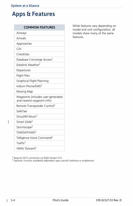
System at a Glance
Apps & Features
1 Requires Wi-Fi connection via Flight Stream 510. 2 Optional. Function availability dependent upon aircraft interfaces or enablement.
COMMON FEATURES
Airways
Arrivals
Approaches
CDI
Checklists
Database Concierge Access1
Datalink Weather2
Departures
Flight Plan
Graphical Flight Planning
Iridium Phone/SMS2
Moving Map
Waypoints (includes user-generated and nearest waypoint info)
Remote Transponder Control2
SafeTaxi
SiriusXM Music2
Smart Glide2
Stormscope2
TAWS/HTAWS2
Telligence Voice Command2
Traffic2
VNAV Descent2
While features vary depending on model and unit configuration, all models share many of the same features.
System at a Glance
190-02327-03 Rev. D Pilot’s Guide 1-7
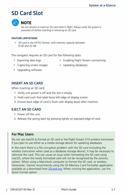
SD Card Slot
NOTEDo not remove or insert an SD card while in flight. Always verify the system is powered off before inserting or removing an SD card.
FEATURE LIMITATIONS
• SD card in the FAT32 format, with memory capacity between8 GB and 32 GB
The navigator requires an SD card for the following tasks.
INSERT AN SD CARDWhen inserting an SD card:
1. Verify unit power is off and the slot is empty.
2. Hold card such that label faces left edge of display screen.
3. Ensure back edge of card is flush with display bezel after insertion.
EJECT AN SD CARD1. Power off the unit.
2. Release the spring latch by pressing lightly on exposed edge of card.
• Exporting data logs • Enabling Flight Stream connectivity
• Capturing screen images • Updating databases
• Upgrading software
For Mac UsersDo not use macOS to format an SD card or the Flight Stream 510 wireless transceiver if you plan to use either as a media storage device for updating databases.
In the event there is a file corruption problem with the SD card (including the wireless transceiver when used as a database storage device), it may be necessary to reformat the card. This can cause an issue when formatting the SD card using macOS, where the newly formatted card will not be recognized by the avionics system. When using a Macintosh computer to format the SD card, or wireless transceiver, Garmin recommends using the SD Memory Card Formatter application available as a download from SDcard.org. When running the application, use the Quick Format option.
1-10 Pilot’s Guide 190-02327-03 Rev. D
System at a Glance
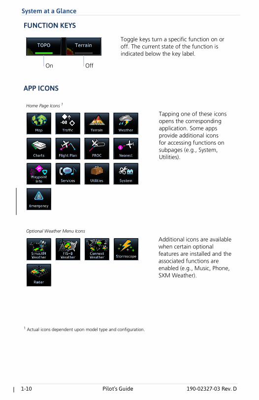
FUNCTION KEYS
APP ICONS
1 Actual icons dependent upon model type and configuration.
Toggle keys turn a specific function on or off. The current state of the function is indicated below the key label.
On Off
Tapping one of these icons opens the corresponding application. Some apps provide additional icons for accessing functions on subpages (e.g., System, Utilities).
Home Page Icons 1
Additional icons are available when certain optional features are installed and the associated functions are enabled (e.g., Music, Phone, SXM Weather).
Optional Weather Menu Icons
2-2 Pilot’s Guide 190-02327-03 Rev. D
Get Started
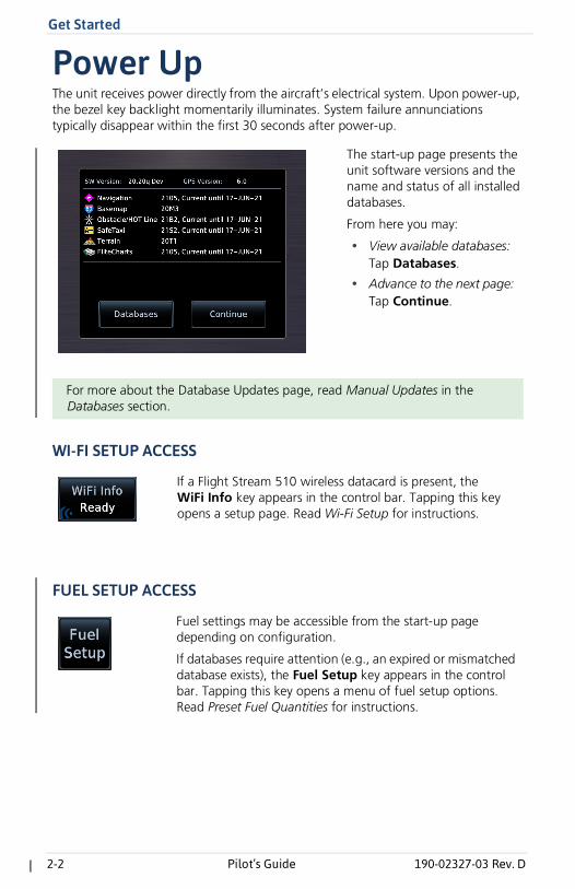
Power UpThe unit receives power directly from the aircraft’s electrical system. Upon power-up, the bezel key backlight momentarily illuminates. System failure annunciations typically disappear within the first 30 seconds after power-up.
WI-FI SETUP ACCESS
FUEL SETUP ACCESS
For more about the Database Updates page, read Manual Updates in the Databases section.
The start-up page presents the unit software versions and the name and status of all installed databases.
From here you may:
• View available databases:Tap Databases.
• Advance to the next page:Tap Continue.
If a Flight Stream 510 wireless datacard is present, the WiFi Info key appears in the control bar. Tapping this key opens a setup page. Read Wi-Fi Setup for instructions.
Fuel settings may be accessible from the start-up page depending on configuration.
If databases require attention (e.g., an expired or mismatched database exists), the Fuel Setup key appears in the control bar. Tapping this key opens a menu of fuel setup options. Read Preset Fuel Quantities for instructions.
Get Started
190-02327-03 Rev. D Pilot’s Guide 2-3
Remote Database ConfirmationFEATURE REQUIREMENTS
• GTN Xi software v20.20 or later
• Second GTN Xi series navigator and/or GDU TXi1
• SD cards containing databases must be removed from the second GTN Xi seriesnavigator and/or GDU TXi unit(s)
FEATURE LIMITATIONS
• Available for dual GTN Xi and GTN Xi/GDU TXi installations only
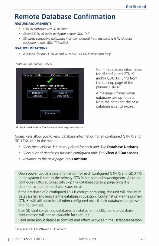
Access keys allow you to view database information for all configured GTN Xi and GDU TXi units in the system.
• View the available database updates for each unit: Tap Database Updates.
• View a list of databases for each configured unit: Tap View All Databases.
• Advance to the next page: Tap Continue.
1 Requires GDU TXi software v3.30 or later.
Upon power up, database information for each configured GTN Xi and GDU TXi in the system is sent to the primary GTN Xi for pilot acknowledgment. All other configured LRUs automatically skip the database start-up page once it is determined that no database issues exist.If the database of a configured LRU is corrupt or missing, the unit will display its database list and indicate the database in question. Confirmation via the primary GTN Xi will still occur for all other configured units if their databases are present and not corrupt.If an SD card containing databases is installed in the LRU, remote database confirmation will not be available for that unit.Read more about database conflicts and effective cycles in the Databases section.
Confirm database information for all configured GTN Xi and/or GDU TXi units from the start-up page of the primary GTN Xi.
A message informs when databases are up to date. Note the date that the next database is set to expire.
Start-up Page, Primary GTN Xi
A check mark means that no databases require attention.
2-4 Pilot’s Guide 190-02327-03 Rev. D
Get Started
Preset Fuel QuantitiesCAUTIONEnsure that estimated fuel quantity values are accurate before flight.
FEATURE LIMITATIONS
For the operating limitations of a specific aircraft, consult the POH.
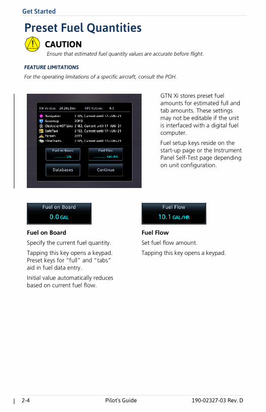
GTN Xi stores preset fuel amounts for estimated full and tab amounts. These settings may not be editable if the unit is interfaced with a digital fuel computer.
Fuel setup keys reside on the start-up page or the Instrument Panel Self-Test page depending on unit configuration.
Fuel on Board
Specify the current fuel quantity.
Tapping this key opens a keypad. Preset keys for “full” and “tabs” aid in fuel data entry.
Initial value automatically reduces based on current fuel flow.
Fuel Flow
Set fuel flow amount.
Tapping this key opens a keypad.
2-6 Pilot’s Guide 190-02327-03 Rev. D
Get Started
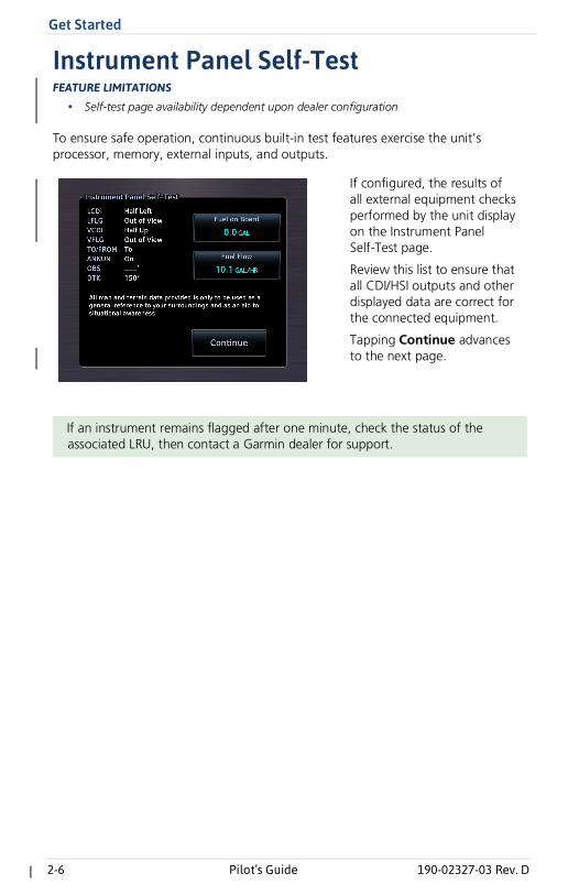
Instrument Panel Self-TestFEATURE LIMITATIONS
• Self-test page availability dependent upon dealer configuration
To ensure safe operation, continuous built-in test features exercise the unit’s processor, memory, external inputs, and outputs.
If an instrument remains flagged after one minute, check the status of the associated LRU, then contact a Garmin dealer for support.
If configured, the results of all external equipment checks performed by the unit display on the Instrument Panel Self-Test page.
Review this list to ensure that all CDI/HSI outputs and other displayed data are correct for the connected equipment.
Tapping Continue advances to the next page.

Get Started
190-02327-03 Rev. D Pilot’s Guide 2-9
Database ConflictsFEATURE LIMITATIONS
• Applicable to dual GTN Xi and GTN Xi/GDU TXi1 installations only
Conflicts occur when the database of a configured GTN Xi or GDU TXi is corrupt, missing, or past its expiration date.
When this happens:
• A caution indication appears on the start-up page of the primary GTN Xi.Depending on the type of conflict, a selectable information key may appearnext to the database name.
• The database list displays on the appropriate LRU (remote confirmation is nolonger available for that unit).
• The database name appears in yellow on both the primary GTN Xi and theassociated LRU.
Resolve database conflicts when they occur.
DATABASE MISMATCH
MISSING DATABASE INFORMATION
1 Applicable only to GDU TXi software v3.30 and later.
Always verify that all LRUs are online before tapping Continue.
Tapping Database Mismatch displays all databases of that particular type and their associated LRUs. Expired or corrupt databases appear in yellow at the top of the list.
A message informs when database information from the indicated LRU is missing. This appears when an LRU is not powered on during start-up.
Get Started
190-02327-03 Rev. D Pilot’s Guide 2-13
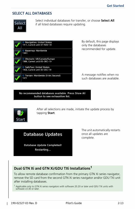
SELECT ALL DATABASES
Dual GTN Xi and GTN Xi/GDU TXi Installations1
To allow remote database confirmation from the primary GTN Xi series navigator, remove the SD card from the second GTN Xi series navigator and/or GDU TXi unit after installing databases.1 Applicable only to GTN Xi series navigators with software 20.20 or later and GDU TXi units with
software v3.30 or later.
Select individual databases for transfer, or choose Select All if all listed databases require updating.
By default, this page displays only the databases recommended for update.
A message notifies when no such databases are available.
After all selections are made, initiate the update process by tapping Start.
The unit automatically restarts once all updates are complete.
2-20 Pilot’s Guide 190-02327-03 Rev. D
Get Started
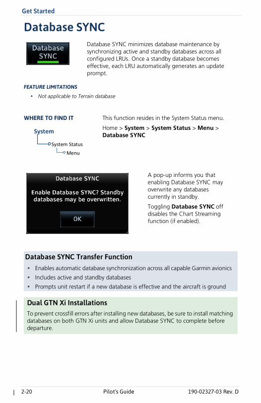
Database SYNC
FEATURE LIMITATIONS
• Not applicable to Terrain database
Database SYNC Transfer Function• Enables automatic database synchronization across all capable Garmin avionics
• Includes active and standby databases
• Prompts unit restart if a new database is effective and the aircraft is ground
Dual GTN Xi Installations
To prevent crossfill errors after installing new databases, be sure to install matching databases on both GTN Xi units and allow Database SYNC to complete before departure.
Database SYNC minimizes database maintenance by synchronizing active and standby databases across all configured LRUs. Once a standby database becomes effective, each LRU automatically generates an update prompt.
System Status
Menu
System
This function resides in the System Status menu.
Home > System > System Status > Menu > Database SYNC
WHERE TO FIND IT
A pop-up informs you that enabling Database SYNC may overwrite any databases currently in standby.
Toggling Database SYNC off disables the Chart Streaming function (if enabled).
2-40 Pilot’s Guide 190-02327-03 Rev. D
Get Started
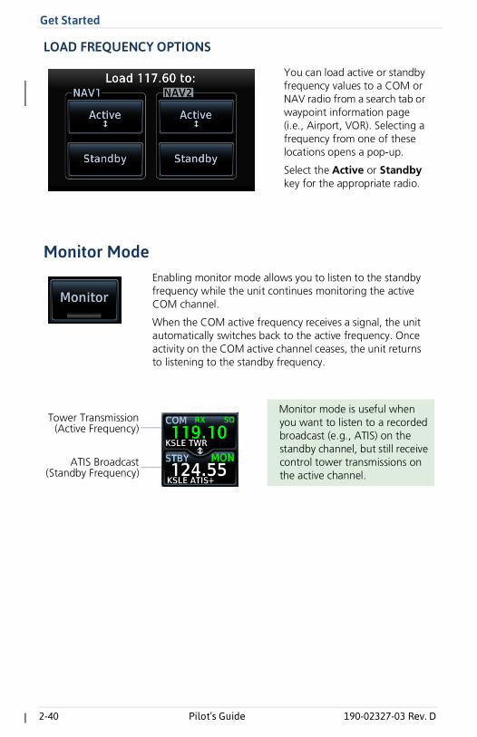
LOAD FREQUENCY OPTIONS
Monitor Mode
You can load active or standby frequency values to a COM or NAV radio from a search tab or waypoint information page (i.e., Airport, VOR). Selecting a frequency from one of these locations opens a pop-up.
Select the Active or Standby key for the appropriate radio.
Enabling monitor mode allows you to listen to the standby frequency while the unit continues monitoring the active COM channel.
When the COM active frequency receives a signal, the unit automatically switches back to the active frequency. Once activity on the COM active channel ceases, the unit returns to listening to the standby frequency.
Monitor mode is useful when you want to listen to a recorded broadcast (e.g., ATIS) on the standby channel, but still receive control tower transmissions on the active channel.
ATIS Broadcast(Standby Frequency)
Tower Transmission(Active Frequency)
Get Started
190-02327-03 Rev. D Pilot’s Guide 2-47
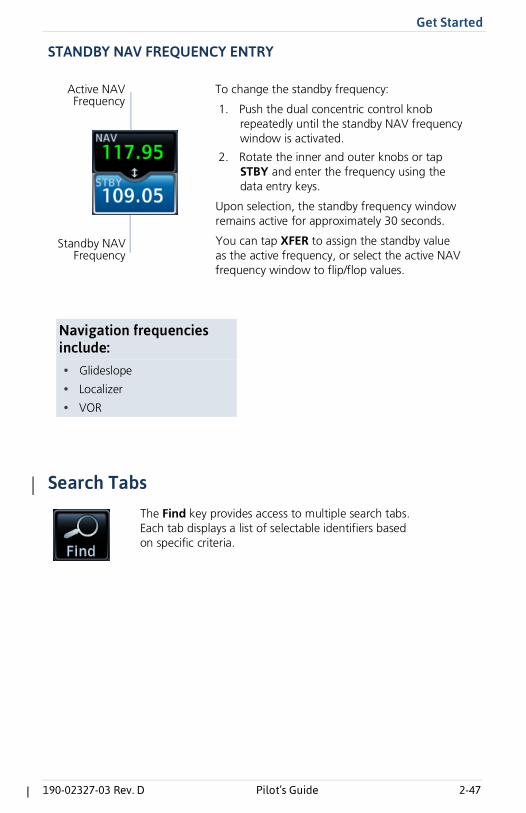
STANDBY NAV FREQUENCY ENTRY
Search Tabs
To change the standby frequency:
1. Push the dual concentric control knob repeatedly until the standby NAV frequency window is activated.
2. Rotate the inner and outer knobs or tap STBY and enter the frequency using the data entry keys.
Upon selection, the standby frequency window remains active for approximately 30 seconds.
You can tap XFER to assign the standby value as the active frequency, or select the active NAV frequency window to flip/flop values.
Active NAVFrequency
Standby NAVFrequency
Navigation frequencies include:• Glideslope
• Localizer
• VOR
The Find key provides access to multiple search tabs. Each tab displays a list of selectable identifiers based on specific criteria.
2-54 Pilot’s Guide 190-02327-03 Rev. D
Get Started
Intercom SetupSetup controls allow you to access:
• Communication modes between pilot, co-pilot, and passenger
• Distribution and mute options for two music interfaces
• Distribution and volume of phone calls
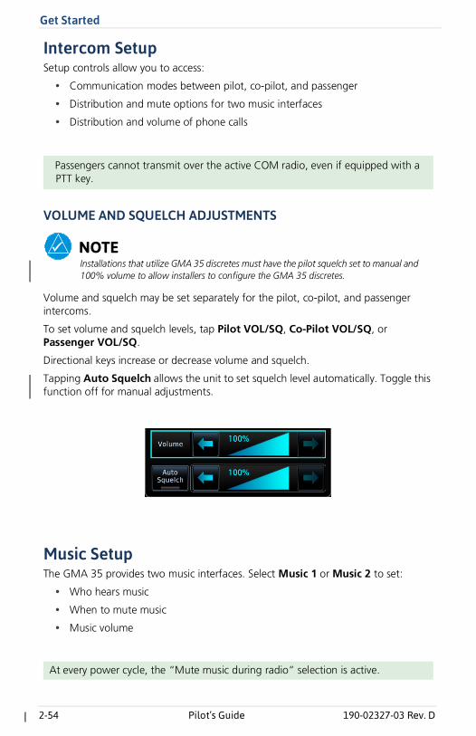
VOLUME AND SQUELCH ADJUSTMENTS
NOTEInstallations that utilize GMA 35 discretes must have the pilot squelch set to manual and 100% volume to allow installers to configure the GMA 35 discretes.
Volume and squelch may be set separately for the pilot, co-pilot, and passenger intercoms.
To set volume and squelch levels, tap Pilot VOL/SQ, Co-Pilot VOL/SQ, or Passenger VOL/SQ.
Directional keys increase or decrease volume and squelch.
Tapping Auto Squelch allows the unit to set squelch level automatically. Toggle this function off for manual adjustments.
Music SetupThe GMA 35 provides two music interfaces. Select Music 1 or Music 2 to set:
• Who hears music
• When to mute music
• Music volume
Passengers cannot transmit over the active COM radio, even if equipped with a PTT key.
At every power cycle, the “Mute music during radio” selection is active.
Get Started
190-02327-03 Rev. D Pilot’s Guide 2-55
Telephone Setup
NOTEWhen using the GSR 56 Iridium phone system, Garmin recommends activating audio only during phone calls.
The GMA 35 provides a 2-way telephone interface and depends on the state of the telephone distribution. Telephone communication is much like using the intercom, allowing both parties to talk at once.
Tap Telephone to set:
• The recipients of a telephone call
• The volume of the telephone call
Bluetooth AudioThe GMA 35c provides an audio connection to a portable device via Bluetooth wireless technology.
Tap Bluetooth to set:
• Who can hear the Bluetooth enabled device
• When to mute audio
• Volume level
Telephone audio distribution is retained across power cycles for the passengers. Pilot and co-pilot telephone distribution deactivates after a power cycle.
2-72 Pilot’s Guide 190-02327-03 Rev. D
Get Started
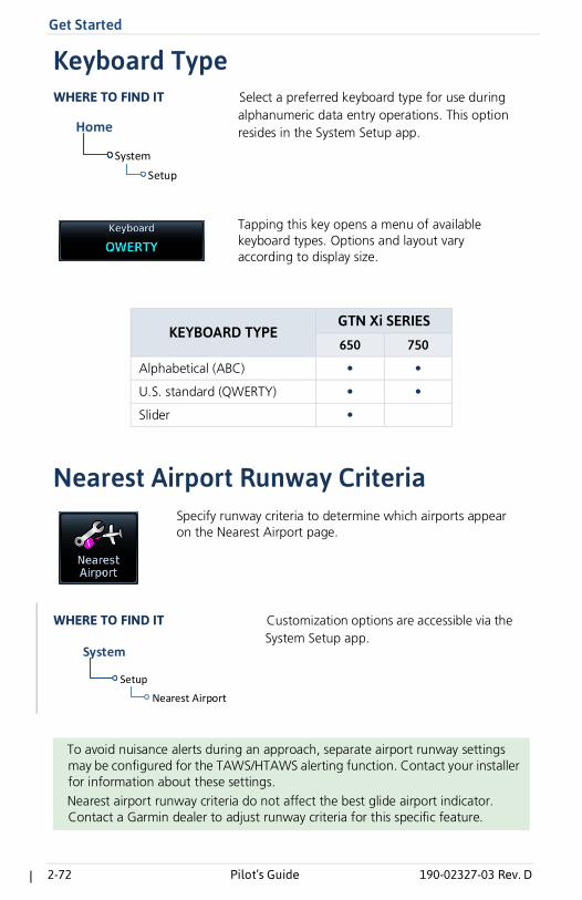
Keyboard Type
Nearest Airport Runway Criteria
KEYBOARD TYPEGTN Xi SERIES
650 750
Alphabetical (ABC) • •
U.S. standard (QWERTY) • •
Slider •
To avoid nuisance alerts during an approach, separate airport runway settings may be configured for the TAWS/HTAWS alerting function. Contact your installer for information about these settings.Nearest airport runway criteria do not affect the best glide airport indicator. Contact a Garmin dealer to adjust runway criteria for this specific feature.
Select a preferred keyboard type for use during alphanumeric data entry operations. This option resides in the System Setup app.
WHERE TO FIND IT
System
Setup
Home
Tapping this key opens a menu of available keyboard types. Options and layout vary according to display size.
Specify runway criteria to determine which airports appear on the Nearest Airport page.
Setup
Nearest Airport
System
Customization options are accessible via the System Setup app.
WHERE TO FIND IT
Get Started
190-02327-03 Rev. D Pilot’s Guide 2-97
1 Pilot setup required.
What happens if there’s a power interruption?
Data logging stops if power is lost. All data recorded up to that point remains stored in the internal memory. Data is not recorded for the duration of the outage. When GTN Xi reboots, data logging automatically resumes with a new log file.
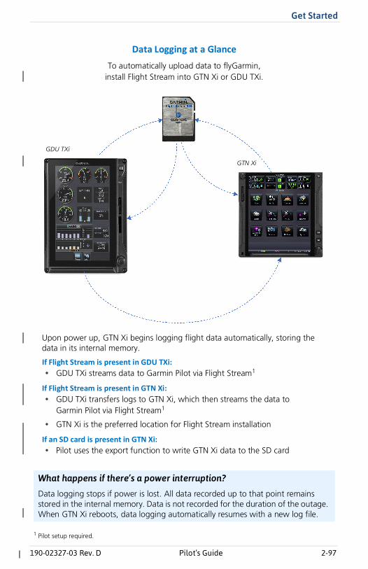
To automatically upload data to flyGarmin,install Flight Stream into GTN Xi or GDU TXi.
Upon power up, GTN Xi begins logging flight data automatically, storing the data in its internal memory.
If Flight Stream is present in GDU TXi:• GDU TXi streams data to Garmin Pilot via Flight Stream1
If Flight Stream is present in GTN Xi:• GDU TXi transfers logs to GTN Xi, which then streams the data to
Garmin Pilot via Flight Stream1
• GTN Xi is the preferred location for Flight Stream installation
If an SD card is present in GTN Xi:• Pilot uses the export function to write GTN Xi data to the SD card
Data Logging at a Glance
GDU TXi
GTN Xi
Navigation
190-02327-03 Rev. D Pilot’s Guide 3-13
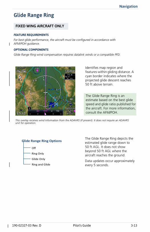
Glide Range Ring
FEATURE REQUIREMENTS
For best glide performance, the aircraft must be configured in accordance with AFM/POH guidance.
OPTIONAL COMPONENTS
Glide Range Ring wind compensation requires datalink winds or a compatible PFD.
FIXED WING AIRCRAFT ONLY
This overlay receives wind information from the ADAHRS (if present). It does not require an ADAHRS unit for operation.
Identifies map region and features within gliding distance. A cyan border indicates where the projected glide descent reaches 50 ft above terrain.
The Glide Range Ring is an estimate based on the best glide speed and glide ratio published for the aircraft. For more information, consult the AFM/POH.
Off
Glide Range Ring Options
Ring and Glide
Glide Only
Ring Only
The Glide Range Ring depicts the estimated glide range down to 50 ft AGL. It does not show beyond 50 ft AGL where the aircraft reaches the ground.
Data updates occur approximately every 5 seconds.
3-42 Pilot’s Guide 190-02327-03 Rev. D
Navigation
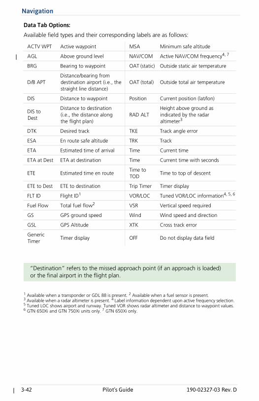
Data Tab Options:
Available field types and their corresponding labels are as follows:
1 Available when a transponder or GDL 88 is present. 2 Available when a fuel sensor is present. 3 Available when a radar altimeter is present. 4 Label information dependent upon active frequency selection. 5 Tuned LOC shows airport and runway. Tuned VOR shows radar altimeter and distance to waypoint values.6 GTN 650Xi and GTN 750Xi units only. 7 GTN 650Xi only.
ACTV WPT Active waypoint MSA Minimum safe altitude
AGL Above ground level NAV/COM Active NAV/COM frequency4, 7
BRG Bearing to waypoint OAT (static) Outside static air temperature
D/B APTDistance/bearing from destination airport (i.e., the straight line distance)
OAT (total) Outside total air temperature
DIS Distance to waypoint Position Current position (lat/lon)
DIS to Dest
Distance to destination (i.e., the distance along the flight plan)
RAD ALTHeight above ground as indicated by the radar altimeter3
DTK Desired track TKE Track angle error
ESA En route safe altitude TRK Track
ETA Estimated time of arrival Time Current time
ETA at Dest ETA at destination Time Current time with seconds
ETE Estimated time en routeTime to TOD
Time to top of descent
ETE to Dest ETE to destination Trip Timer Timer display
FLT ID Flight ID1 VOR/LOC Tuned VOR/LOC information4, 5, 6
Fuel Flow Total fuel flow2 VSR Vertical speed required
GS GPS ground speed Wind Wind speed and direction
GSL GPS Altitude XTK Cross track error
Generic Timer
Timer display OFF Do not display data field
“Destination” refers to the missed approach point (if an approach is loaded) or the final airport in the flight plan.
Navigation
190-02327-03 Rev. D Pilot’s Guide 3-49
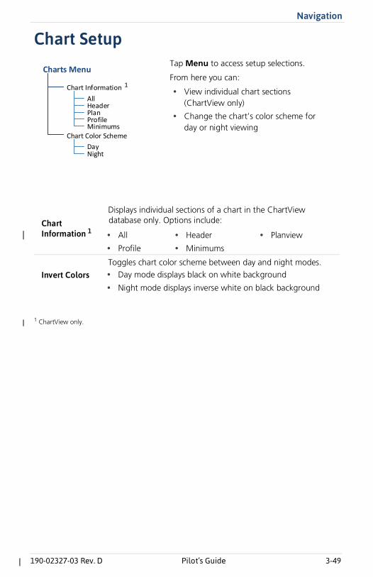
Chart Setup
1 ChartView only.
Chart Information 1
Displays individual sections of a chart in the ChartView database only. Options include:
• All
• Profile
• Header
• Minimums
• Planview
Invert ColorsToggles chart color scheme between day and night modes. • Day mode displays black on white background
• Night mode displays inverse white on black background
Tap Menu to access setup selections.
From here you can:
• View individual chart sections (ChartView only)
• Change the chart’s color scheme for day or night viewing
Chart Information
DayNight
Chart Color SchemeMinimums
Charts Menu
AllHeaderPlanProfile
1
3-122 Pilot’s Guide 190-02327-03 Rev. D
Navigation
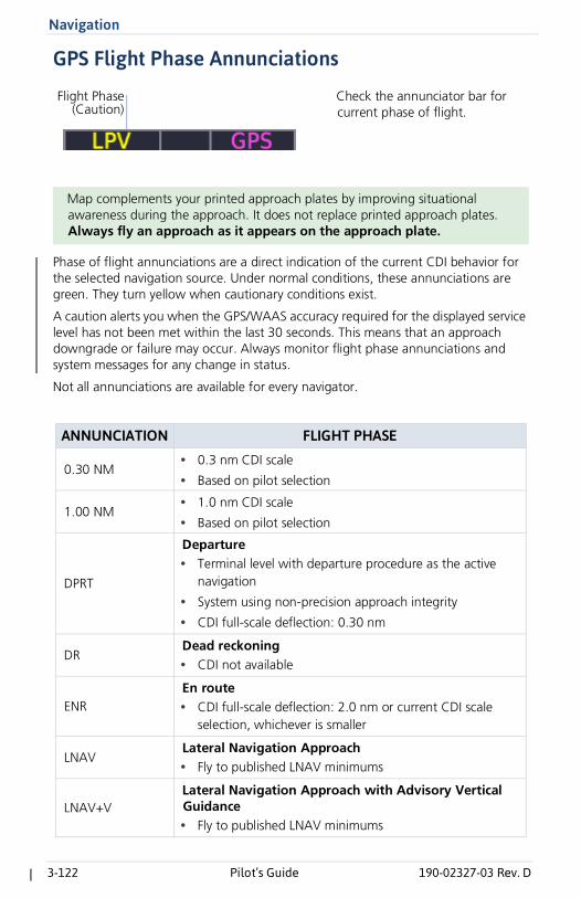
GPS Flight Phase Annunciations
Phase of flight annunciations are a direct indication of the current CDI behavior for the selected navigation source. Under normal conditions, these annunciations are green. They turn yellow when cautionary conditions exist.
A caution alerts you when the GPS/WAAS accuracy required for the displayed service level has not been met within the last 30 seconds. This means that an approach downgrade or failure may occur. Always monitor flight phase annunciations and system messages for any change in status.
Not all annunciations are available for every navigator.
Map complements your printed approach plates by improving situational awareness during the approach. It does not replace printed approach plates. Always fly an approach as it appears on the approach plate.
ANNUNCIATION FLIGHT PHASE
0.30 NM• 0.3 nm CDI scale
• Based on pilot selection
1.00 NM• 1.0 nm CDI scale
• Based on pilot selection
DPRT
Departure• Terminal level with departure procedure as the active
navigation
• System using non-precision approach integrity
• CDI full-scale deflection: 0.30 nm
DRDead reckoning• CDI not available
ENREn route• CDI full-scale deflection: 2.0 nm or current CDI scale
selection, whichever is smaller
LNAVLateral Navigation Approach• Fly to published LNAV minimums
LNAV+VLateral Navigation Approach with Advisory Vertical Guidance • Fly to published LNAV minimums
Check the annunciator bar for current phase of flight.
Flight Phase(Caution)
Navigation
190-02327-03 Rev. D Pilot’s Guide 3-135
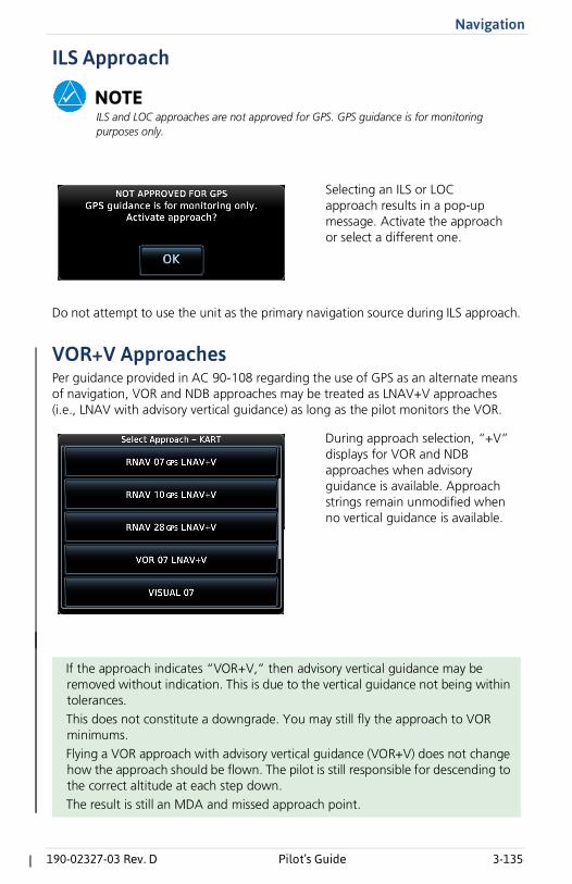
ILS Approach
NOTEILS and LOC approaches are not approved for GPS. GPS guidance is for monitoring purposes only.
Do not attempt to use the unit as the primary navigation source during ILS approach.
VOR+V ApproachesPer guidance provided in AC 90-108 regarding the use of GPS as an alternate means of navigation, VOR and NDB approaches may be treated as LNAV+V approaches (i.e., LNAV with advisory vertical guidance) as long as the pilot monitors the VOR.
If the approach indicates “VOR+V,” then advisory vertical guidance may be removed without indication. This is due to the vertical guidance not being within tolerances.This does not constitute a downgrade. You may still fly the approach to VOR minimums.Flying a VOR approach with advisory vertical guidance (VOR+V) does not change how the approach should be flown. The pilot is still responsible for descending to the correct altitude at each step down.The result is still an MDA and missed approach point.
Selecting an ILS or LOC approach results in a pop-up message. Activate the approach or select a different one.
During approach selection, “+V” displays for VOR and NDB approaches when advisory guidance is available. Approach strings remain unmodified when no vertical guidance is available.
3-140 Pilot’s Guide 190-02327-03 Rev. D
Navigation
If pilot exceeds the horizontal alarm limits:
• Approach downgrades to non-precision
• “LNAV” annunciates on Map to inform of the change
• Advisory message: “GPS approach downgraded. Use LNAV minima.”
• Pilot continues approach using LNAV non-precision minimums, if applicable
If GPS integrity does not meet the non-precision horizontal alarm limits:
• Advisory message: “Abort Approach. GPS approach is no longer available.”
• Pilot acknowledges message
• Unit reverts to terminal limits of 1 nm to support navigation to the missed approach
When crossing the final approach fix:
• Waypoint sequences to the missed approach point (e.g., RW31, the runway threshold)
• Pilot flies toward missed approach point, keeping the needle on the external CDI (or HSI) at center, observing published altitude minimums
• Final course segment becomes the active flight plan leg on Map
Approaching missed approach point:
• Advisory message: “Arriving at Waypoint.”
If the approach indicates “LP+V,” then advisory vertical guidance may be removed without indication. This is due to the vertical guidance not being within tolerances.This does not constitute a downgrade. You may still fly the approach to LP minimums.Flying an LP approach with advisory vertical guidance (LP+V) does not change how the approach should be flown. The pilot is still responsible for descending to the correct altitude at each step down.The result is still an MDA and missed approach point.
5-50 Pilot’s Guide 190-02327-03 Rev. D
Hazard Awareness
Stormscope
WARNINGDo not exclusively use the lightning detection system for weather avoidance. The system may display inaccurate or incomplete information. For additional information, consult the lightning detection system documentation.
FEATURE REQUIREMENTS
• WX-500 Stormscope Weather Mapping Sensor
FEATURE LIMITATIONS
• Stormscope lightning information cannot display concurrently with a datalinklightning weather product (SiriusXM, Connext, or FIS-B)
Stormscope Features• Passive weather avoidance system
• Detects electrical discharges from thunderstorms within 200 nm of currentposition
• Plots strike count and relative bearing location every two seconds
• Heading and distance from aircraft
• Arc and 360º viewing options
For more information, consult the WX-500 pilot’s guide.
Stormscope lightning information displays on a dedicated weather page and as overlays on Map.
5-70 Pilot’s Guide 190-02327-03 Rev. D
Hazard Awareness
Traffic AwarenessWARNINGDo not rely solely upon the display of traffic information for collision avoidance maneuvering. The traffic display does not provide collision avoidance resolution advisories and does not under any circumstances or conditions relieve the pilot's responsibility to see and avoid other aircraft.
FEATURE LIMITATIONS
• Traffic symbols vary according to traffic source (e.g., TIS-A, TAS, ADS-B)
• Intruding aircraft without altitude reporting capabilities do not display altitudeseparation data or climb /descent indications
• Available display ranges and vector types are dependent upon traffic source
Available Traffic Sources• TIS-A
• TCAD 9900B
• TCAD 9900BX
• Ryan TCAD 9900BXw/GDL 88
• TAS/TCAS I
• TCAS II
• ADS-B
Available functions, alerting features, and options are dependent upon on the traffic system source.
ADS-B controls are accessible from the Traffic setup menu. Controls for other traffic systems reside in a control menu and/or on the Traffic page.
5-102 Pilot’s Guide 190-02327-03 Rev. D
Hazard Awareness
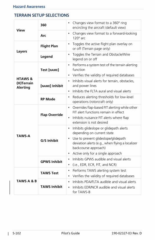
TERRAIN SETUP SELECTIONS
View
360• Changes view format to a 360º ring
encircling the aircraft (default view)
Arc• Changes view format to a forward-looking
120º arc
Layers
Flight Plan• Toggles the active flight plan overlay on
or off (Terrain page only)
Legend• Toggles the Terrain and Obstacle/Wire
legend on or off
HTAWS & (H)Terrain Alerting
Test [NAME]• Performs a system test of the terrain alerting
function
• Verifies the validity of required databases
[NAME] Inhibit• Inhibits visual alerts for terrain, obstacles,
and power lines
• Inhibits the FLTA aural and visual alerts
RP Mode• Reduces alerting thresholds for low-level
operations (rotorcraft only)
TAWS-A
Flap Override
• Overrides flap-based FIT alerting while other FIT alert functions remain in effect
• Inhibits nuisance FIT alerts where flap extension is not desired
G/S Inhibit
• Inhibits glideslope or glidepath alerts depending on current state
• Use to prevent glideslope/glidepath deviation alerts (e.g., when flying a localizer backcourse approach)
• Active only for a single approach
GPWS Inhibit• Inhibits GPWS audible and visual alerts
• (i.e., EDR, ECR, FIT, and NCR)
TAWS A & B
TAWS Test• Performs TAWS alerting system test
• Verifies the validity of required databases
TAWS Inhibit• Inhibits PDA/FLTA audible and visual alerts
• Inhibits EDR/NCR audible and visual alerts for TAWS-B
Hazard Awareness
190-02327-03 Rev. D Pilot’s Guide 5-119
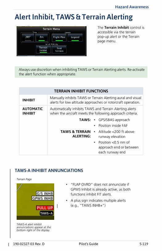
Alert Inhibit, TAWS & Terrain Alerting
TAWS-A INHIBIT ANNUNCIATIONS
Always use discretion when inhibiting TAWS or Terrain Alerting alerts. Re-activate the alert function when appropriate.
TERRAIN INHIBIT FUNCTIONS
INHIBIT Manually inhibits TAWS or Terrain Alerting aural and visual alerts for low altitude approaches or rotorcraft operation.
AUTOMATIC INHIBIT
Automatically inhibits TAWS and Terrain Alerting alerts when the aircraft meets the following approach criteria.
TAWS: • GPS/SBAS approach
• Position inside FAF
TAWS & TERRAINALERTING:
• Altitude <200 ft above runway elevation
• Position <0.5 nm of approach end or between each runway end
The Terrain Inhibit control is accessible via the terrain pop-up alert or the Terrain page menu.
• “FLAP OVRD” does not annunciate if GPWS Inhibit is already active, as both functions inhibit FIT alerts.
• A plus sign indicates multiple alerts (e.g., “TAWS INHB+”)
Terrain Page
TAWS-A alert inhibit annunciations appear at the bottom right of the display.
5-136 Pilot’s Guide 190-02327-03 Rev. D
Hazard Awareness
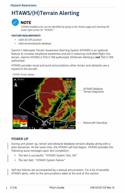
HTAWS/(H)Terrain Alerting
NOTEHTAWS-enabled units can be identified by going to the Terrain page and checking the lower right-corner for “HTAWS.”
FEATURE REQUIREMENTS
• Valid 3D GPS position
• Valid terrain/obstacle database
Garmin’s Helicopter Terrain Awareness Warning System (HTAWS) is an optional feature to increase situational awareness and aid in reducing controlled flight into terrain. Garmin HTAWS is TSO-C194 authorized. (H)Terrain Alerting is not TSO-C194 authorized.
HTAWS provides visual and aural annunciations when terrain and obstacles are a hazard to the aircraft.
POWER UPDuring unit power up, terrain and obstacle database versions display along with a pilot disclaimer. At the same time, the HTAWS self-test begins. HTAWS provides the following aural messages upon test completion:
• The test is successful: “HTAWS System Test, OK”
• The test fails: “HTAWS System Failure”
Self-test failures are accompanied by a textual annunciation. For a list of possible HTAWS alerts, refer to the annunciations table at the end of this section.
Rotorcraft Ownship
HTAWS Relative Terrain Depiction
HTAWS Terrain Display
6-2 Pilot’s Guide 190-02327-03 Rev. D
Abnormal Operations
Emergency Modes at a Glance
NOTEWhile emergency features can assist in workload reduction, it is the responsibility of the pilot in command to know and follow all published AFM/POH normal and emergency procedures.
Contact a Garmin dealer to see if emergency features are available for your aircraft.
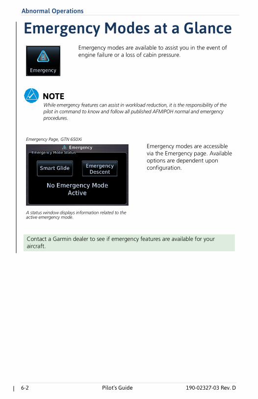
Emergency modes are available to assist you in the event of engine failure or a loss of cabin pressure.
Emergency modes are accessible via the Emergency page. Available options are dependent upon configuration.
A status window displays information related to the active emergency mode.
Emergency Page, GTN 650Xi
Abnormal Operations
190-02327-03 Rev. D Pilot’s Guide 6-3
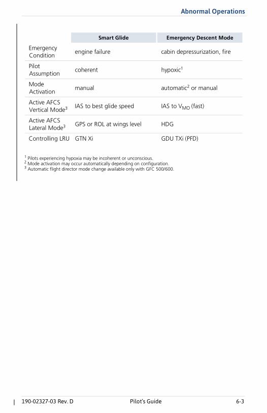
1 Pilots experiencing hypoxia may be incoherent or unconscious.2 Mode activation may occur automatically depending on configuration.3 Automatic flight director mode change available only with GFC 500/600.
Smart Glide Emergency Descent Mode
EmergencyCondition
engine failure cabin depressurization, fire
Pilot Assumption
coherent hypoxic1
Mode Activation
manual automatic2 or manual
Active AFCS Vertical Mode3 IAS to best glide speed IAS to VMO (fast)
Active AFCS Lateral Mode3 GPS or ROL at wings level HDG
Controlling LRU GTN Xi GDU TXi (PFD)
6-4 Pilot’s Guide 190-02327-03 Rev. D
Abnormal Operations
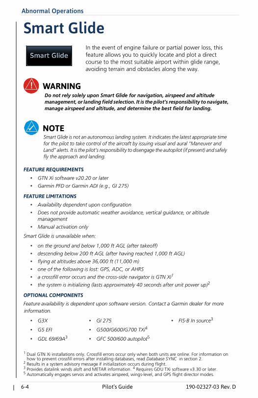
Smart Glide
WARNINGDo not rely solely upon Smart Glide for navigation, airspeed and altitude management, or landing field selection. It is the pilot’s responsibility to navigate, manage airspeed and altitude, and determine the best field for landing.
NOTESmart Glide is not an autonomous landing system. It indicates the latest appropriate time for the pilot to take control of the aircraft by issuing visual and aural “Maneuver and Land” alerts. It is the pilot’s responsibility to disengage the autopilot (if present) and safely fly the approach and landing.
FEATURE REQUIREMENTS
• GTN Xi software v20.20 or later
• Garmin PFD or Garmin ADI (e.g., GI 275)
FEATURE LIMITATIONS
• Availability dependent upon configuration
• Does not provide automatic weather avoidance, vertical guidance, or altitudemanagement
• Manual activation only
Smart Glide is unavailable when:
• on the ground and below 1,000 ft AGL (after takeoff)
• descending below 200 ft AGL (after having reached 1,000 ft AGL)
• flying at altitudes above 36,000 ft (11,000 m)
• one of the following is lost: GPS, ADC, or AHRS
• a crossfill error occurs and the cross-side navigator is GTN Xi1
• the system is initializing (lasts approximately 40 seconds after unit power up)2
OPTIONAL COMPONENTS
Feature availability is dependent upon software version. Contact a Garmin dealer for more information.
1 Dual GTN Xi installations only. Crossfill errors occur only when both units are online. For information on how to prevent crossfill errors after installing databases, read Database SYNC in section 2.
2 Results in a system advisory message if initialization occurs during flight. 3 Provides datalink winds aloft and METAR information. 4 Requires GDU TXi software v3.30 or later.5 Automatically engages servos and activates airspeed, wings-level, and GPS flight director modes.
• G3X • GI 275 • FIS-B In source3
• G5 EFI • G500/G600/G700 TXi4
• GDL 69/69A3 • GFC 500/600 autopilot5
In the event of engine failure or partial power loss, this feature allows you to quickly locate and plot a direct course to the most suitable airport within glide range, avoiding terrain and obstacles along the way.
Abnormal Operations
190-02327-03 Rev. D Pilot’s Guide 6-5
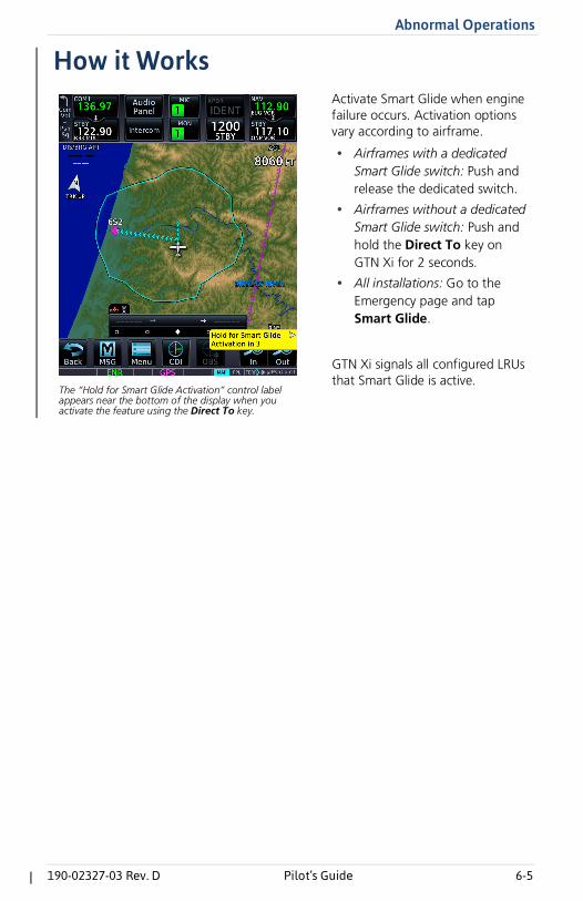
How it WorksActivate Smart Glide when engine failure occurs. Activation options vary according to airframe.
• Airframes with a dedicatedSmart Glide switch: Push andrelease the dedicated switch.
• Airframes without a dedicatedSmart Glide switch: Push andhold the Direct To key onGTN Xi for 2 seconds.
• All installations: Go to theEmergency page and tapSmart Glide.
GTN Xi signals all configured LRUs that Smart Glide is active.
The “Hold for Smart Glide Activation” control label appears near the bottom of the display when you activate the feature using the Direct To key.
6-6 Pilot’s Guide 190-02327-03 Rev. D
Abnormal Operations
UPON ACTIVATION
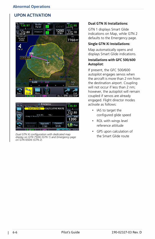
Dual GTN Xi Installations:
GTN 1 displays Smart Glide indications on Map, while GTN 2 defaults to the Emergency page.
Single GTN Xi Installations:
Map automatically opens and displays Smart Glide indications.
Installations with GFC 500/600 Autopilot:
If present, the GFC 500/600 autopilot engages servos when the aircraft is more than 2 nm from the destination airport. Coupling will not occur if less than 2 nm; however, the autopilot will remain coupled if servos are already engaged. Flight director modes activate as follows:
• IAS to target theconfigured glide speed
• ROL with wings levelreference attitude
• GPS upon calculation ofthe Smart Glide routeDual GTN Xi configuration with dedicated map
display on GTN 750Xi (GTN 1) and Emergency page on GTN 650Xi (GTN 2).
Abnormal Operations
190-02327-03 Rev. D Pilot’s Guide 6-7
Smart Glide FunctionFunctionality changes based on whether or not a suitable destination airport is within the estimated glide range.
Suitable airport within glide range:• Configures Map to show pertinent glide information, including
Smart Glide Range Ring and arrival AGL
• Replaces existing flight plan with a direct glide route to a suitable destinationairport
• Provides a list of alternate airports that are within the estimated glide range
• Indicates the best glide speed for the aircraft at gross weight
• Triggers autopilot flight director modes to target configured best glide speedand follow the GPS Smart Glide direct-to route1
• Alerts pilot if glide destination falls outside the Smart Glide Range Ring
• Allows direct tuning of emergency transponder code 77002
• Tunes standby COM to destination CTAF or tower frequency
• CDI scale is set to 0.30 nm
No suitable airport within glide range:• Configures Map to show pertinent glide information, including
Smart Glide Range Ring
• Indicates the best glide speed for the aircraft at gross weight
• Triggers autopilot flight director modes to target configured best glide speedand level the wings1
• Allows direct tuning of emergency transponder code 77002
• Tunes standby COM to emergency frequency 121.5
• Provides altitude voice callouts for 2,000, 1,000, and 500 ft AGL
1 Requires a GFC 500/600 autopilot. 2 Requires a compatible transponder that can be controlled from GTN Xi.
6-8 Pilot’s Guide 190-02327-03 Rev. D
Abnormal Operations
DURING SMART GLIDE MODE
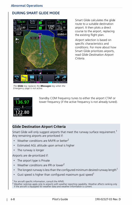
Glide Destination Airport CriteriaSmart Glide will only suggest airports that meet the runway surface requirement.1 Any remaining airports are prioritized if:
• Weather conditions are MVFR or better2
• Estimated AGL altitude upon arrival is higher
• The runway is longer
Airports are de-prioritized if:
• The airport type is Private
• Weather conditions are IFR or lower2
• The longest runway is less than the configured minimum desired runway length1
• Gust speed is higher than configured maximum gust speed1
1 For aircraft specific information, consult the AFMS.2 Weather rankings apply only to airports with weather reporting capability. Weather affects ranking only
if the aircraft is equipped for weather data and weather information is current.
Smart Glide calculates the glide route to a suitable destination airport. It then plots a direct course to the airport, replacing the existing flight plan.
Airport selection is based on specific characteristics and conditions. For more about how Smart Glide prioritizes airports, read Glide Destination Airport Criteria.
The Glide key replaces the Messages key when the Emergency page is not active.
Standby COM frequency tunes to either the airport CTAF or tower frequency (if the active frequency is not already tuned).
Abnormal Operations
190-02327-03 Rev. D Pilot’s Guide 6-9
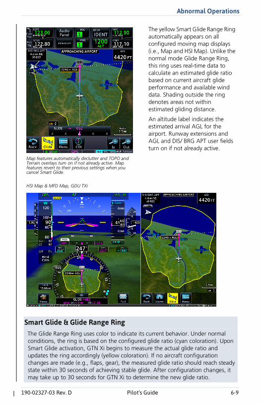
Smart Glide & Glide Range RingThe Glide Range Ring uses color to indicate its current behavior. Under normal conditions, the ring is based on the configured glide ratio (cyan coloration). Upon Smart Glide activation, GTN Xi begins to measure the actual glide ratio and updates the ring accordingly (yellow coloration). If no aircraft configuration changes are made (e.g., flaps, gear), the measured glide ratio should reach steady state within 30 seconds of achieving stable glide. After configuration changes, it may take up to 30 seconds for GTN Xi to determine the new glide ratio.
The yellow Smart Glide Range Ring automatically appears on all configured moving map displays (i.e., Map and HSI Map). Unlike the normal mode Glide Range Ring, this ring uses real-time data to calculate an estimated glide ratio based on current aircraft glide performance and available wind data. Shading outside the ring denotes areas not within estimated gliding distance.
An altitude label indicates the estimated arrival AGL for the airport. Runway extensions and AGL and DIS/ BRG APT user fields turn on if not already active.
Map features automatically declutter and TOPO and Terrain overlays turn on if not already active. Map features revert to their previous settings when you cancel Smart Glide.
HSI Map & MFD Map, GDU TXi
6-10 Pilot’s Guide 190-02327-03 Rev. D
Abnormal Operations
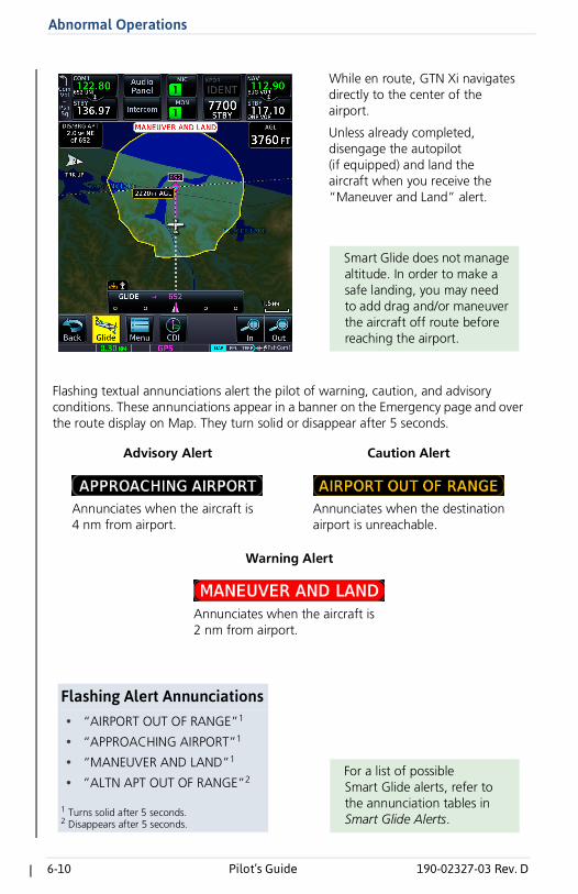
Flashing textual annunciations alert the pilot of warning, caution, and advisory conditions. These annunciations appear in a banner on the Emergency page and over the route display on Map. They turn solid or disappear after 5 seconds.
While en route, GTN Xi navigates directly to the center of the airport.
Unless already completed, disengage the autopilot (if equipped) and land the aircraft when you receive the “Maneuver and Land” alert.
Smart Glide does not manage altitude. In order to make a safe landing, you may need to add drag and/or maneuver the aircraft off route before reaching the airport.
Annunciates when the aircraft is 4 nm from airport.
Annunciates when the destination airport is unreachable.
Advisory Alert Caution Alert
Annunciates when the aircraft is 2 nm from airport.
Warning Alert
Flashing Alert Annunciations• “AIRPORT OUT OF RANGE”1
• “APPROACHING AIRPORT”1
• “MANEUVER AND LAND”1
• ”ALTN APT OUT OF RANGE”2
1 Turns solid after 5 seconds.2 Disappears after 5 seconds.
For a list of possible Smart Glide alerts, refer to the annunciation tables in Smart Glide Alerts.
Abnormal Operations
190-02327-03 Rev. D Pilot’s Guide 6-11
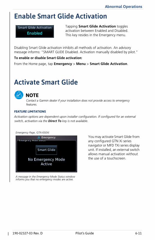
Enable Smart Glide Activation
Disabling Smart Glide activation inhibits all methods of activation. An advisory message informs: “SMART GLIDE Disabled. Activation manually disabled by pilot.”
To enable or disable Smart Glide activation:
From the Home page, tap Emergency > Menu > Smart Glide Activation.
Activate Smart Glide
NOTEContact a Garmin dealer if your installation does not provide access to emergency features.
FEATURE LIMITATIONS
Activation options are dependent upon installer configuration. If configured for an external switch, activation via the Direct To key is not available.
Tapping Smart Glide Activation toggles activation between Enabled and Disabled. This key resides in the Emergency menu.
You may activate Smart Glide from any configured GTN Xi series navigator or MFD TXi series display unit. If installed, an external switch allows manual activation without the use of a touchscreen.
A message in the Emergency Mode Status window informs you that no emergency modes are active.
Emergency Page, GTN 650Xi
6-12 Pilot’s Guide 190-02327-03 Rev. D
Abnormal Operations
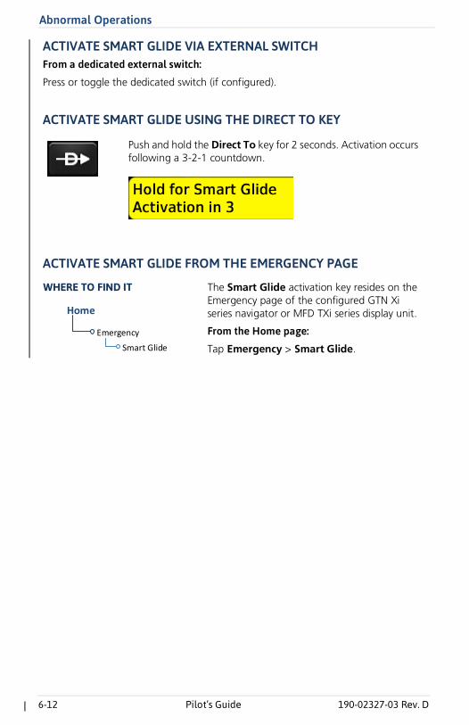
ACTIVATE SMART GLIDE VIA EXTERNAL SWITCHFrom a dedicated external switch:
Press or toggle the dedicated switch (if configured).
ACTIVATE SMART GLIDE USING THE DIRECT TO KEY
ACTIVATE SMART GLIDE FROM THE EMERGENCY PAGE
Push and hold the Direct To key for 2 seconds. Activation occurs following a 3-2-1 countdown.
Emergency
Smart Glide
Home
The Smart Glide activation key resides on the Emergency page of the configured GTN Xi series navigator or MFD TXi series display unit.
From the Home page:
Tap Emergency > Smart Glide.
WHERE TO FIND IT
Abnormal Operations
190-02327-03 Rev. D Pilot’s Guide 6-13
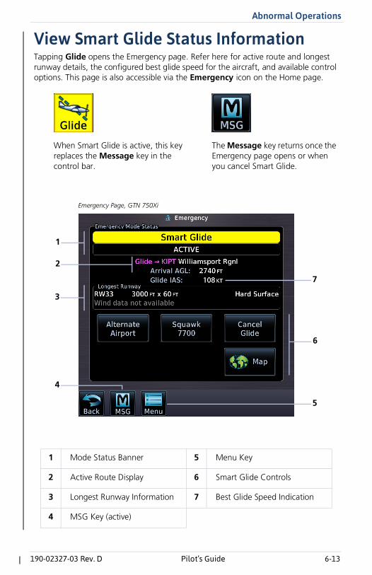
View Smart Glide Status InformationTapping Glide opens the Emergency page. Refer here for active route and longest runway details, the configured best glide speed for the aircraft, and available control options. This page is also accessible via the Emergency icon on the Home page.
1 Mode Status Banner 5 Menu Key
2 Active Route Display 6 Smart Glide Controls
3 Longest Runway Information 7 Best Glide Speed Indication
4 MSG Key (active)
When Smart Glide is active, this key replaces the Message key in the control bar.
The Message key returns once the Emergency page opens or when you cancel Smart Glide.
Emergency Page, GTN 750Xi
1
2
7
6
3
5
4
6-14 Pilot’s Guide 190-02327-03 Rev. D
Abnormal Operations
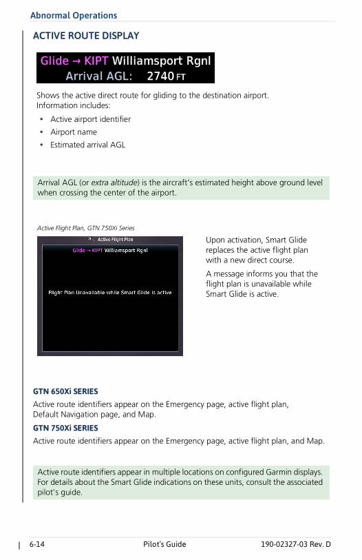
ACTIVE ROUTE DISPLAY
GTN 650Xi SERIESActive route identifiers appear on the Emergency page, active flight plan, Default Navigation page, and Map.
GTN 750Xi SERIESActive route identifiers appear on the Emergency page, active flight plan, and Map.
Arrival AGL (or extra altitude) is the aircraft’s estimated height above ground level when crossing the center of the airport.
Active route identifiers appear in multiple locations on configured Garmin displays. For details about the Smart Glide indications on these units, consult the associated pilot’s guide.
Shows the active direct route for gliding to the destination airport. Information includes:
• Active airport identifier
• Airport name
• Estimated arrival AGL
Upon activation, Smart Glide replaces the active flight plan with a new direct course.
A message informs you that the flight plan is unavailable while Smart Glide is active.
Active Flight Plan, GTN 750Xi Series
Abnormal Operations
190-02327-03 Rev. D Pilot’s Guide 6-15
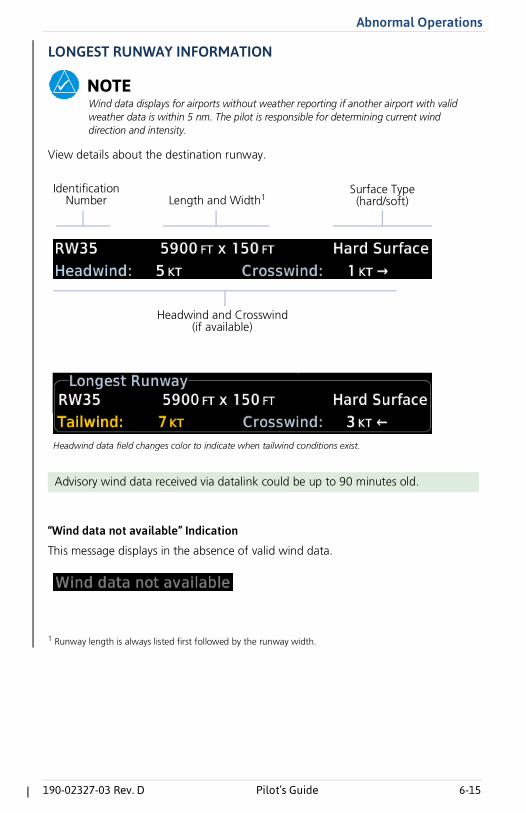
LONGEST RUNWAY INFORMATION
NOTEWind data displays for airports without weather reporting if another airport with valid weather data is within 5 nm. The pilot is responsible for determining current wind direction and intensity.
View details about the destination runway.
“Wind data not available” Indication
This message displays in the absence of valid wind data.
1 Runway length is always listed first followed by the runway width.
Advisory wind data received via datalink could be up to 90 minutes old.
Headwind and Crosswind(if available)
IdentificationNumber Length and Width1
Surface Type(hard/soft)
[To include image.]
Headwind data field changes color to indicate when tailwind conditions exist.
6-16 Pilot’s Guide 190-02327-03 Rev. D
Abnormal Operations
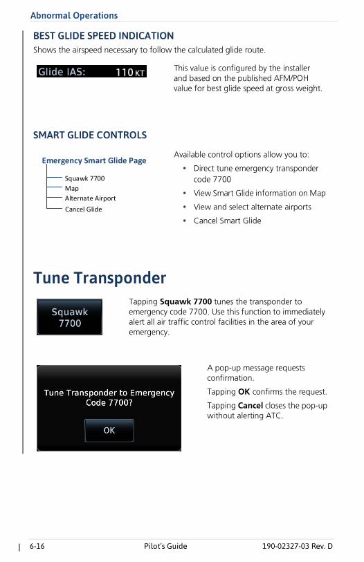
BEST GLIDE SPEED INDICATIONShows the airspeed necessary to follow the calculated glide route.
SMART GLIDE CONTROLS
Tune Transponder
This value is configured by the installer and based on the published AFM/POH value for best glide speed at gross weight.
Available control options allow you to:
• Direct tune emergency transpondercode 7700
• View Smart Glide information on Map
• View and select alternate airports
• Cancel Smart GlideCancel Glide
Squawk 7700
Map
Alternate Airport
Emergency Smart Glide Page
Tapping Squawk 7700 tunes the transponder to emergency code 7700. Use this function to immediately alert all air traffic control facilities in the area of your emergency.
A pop-up message requests confirmation.
Tapping OK confirms the request.
Tapping Cancel closes the pop-up without alerting ATC.
Abnormal Operations
190-02327-03 Rev. D Pilot’s Guide 6-17
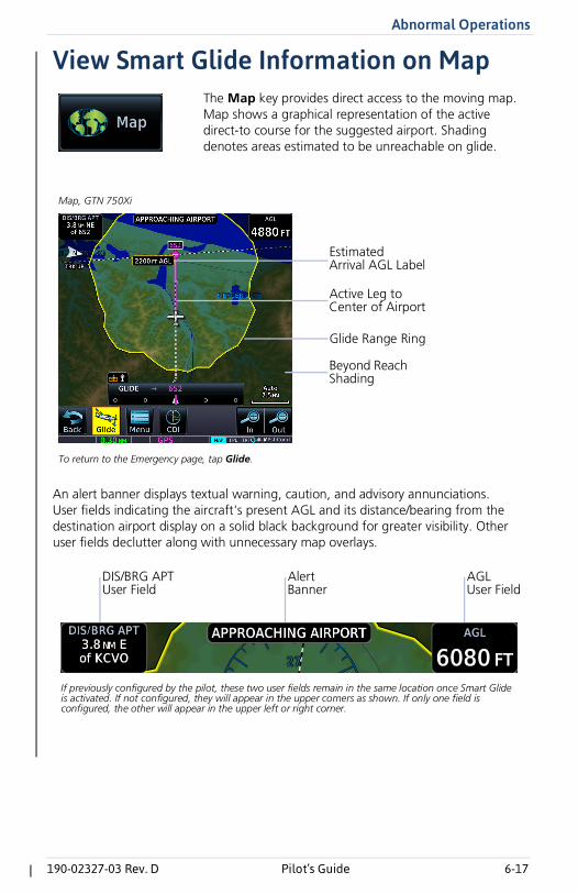
View Smart Glide Information on Map
An alert banner displays textual warning, caution, and advisory annunciations. User fields indicating the aircraft's present AGL and its distance/bearing from the destination airport display on a solid black background for greater visibility. Other user fields declutter along with unnecessary map overlays.
The Map key provides direct access to the moving map. Map shows a graphical representation of the active direct-to course for the suggested airport. Shading denotes areas estimated to be unreachable on glide.
Map, GTN 750Xi
To return to the Emergency page, tap Glide.
Beyond Reach Shading
Active Leg to Center of Airport
Glide Range Ring
Estimated Arrival AGL Label
AGL User Field
DIS/BRG APTUser Field
AlertBanner
If previously configured by the pilot, these two user fields remain in the same location once Smart Glide is activated. If not configured, they will appear in the upper corners as shown. If only one field is configured, the other will appear in the upper left or right corner.
6-18 Pilot’s Guide 190-02327-03 Rev. D
Abnormal Operations
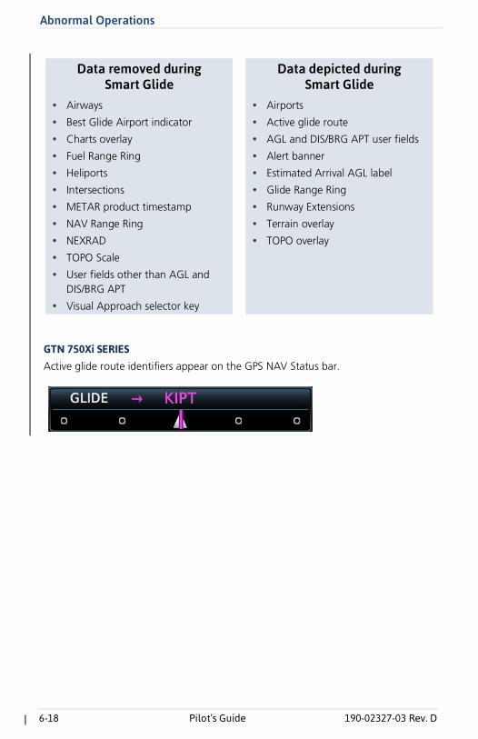
GTN 750Xi SERIESActive glide route identifiers appear on the GPS NAV Status bar.
Data removed duringSmart Glide
Data depicted duringSmart Glide
• Airways
• Best Glide Airport indicator
• Charts overlay
• Fuel Range Ring
• Heliports
• Intersections
• METAR product timestamp
• NAV Range Ring
• NEXRAD
• TOPO Scale
• User fields other than AGL andDIS/BRG APT
• Visual Approach selector key
• Airports
• Active glide route
• AGL and DIS/BRG APT user fields
• Alert banner
• Estimated Arrival AGL label
• Glide Range Ring
• Runway Extensions
• Terrain overlay
• TOPO overlay
Abnormal Operations
190-02327-03 Rev. D Pilot’s Guide 6-19
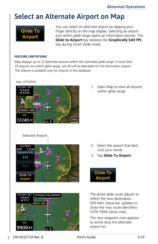
Select an Alternate Airport on Map
FEATURE LIMITATIONS
Map displays up to 25 alternate airports within the estimated glide range. If more than 25 airports are within glide range, not all will be selectable for the destination airport. This feature is available only for airports in the database.
You can select an alternate airport by tapping your finger directly on the map display. Selecting an airport icon within glide range opens an information banner. The Glide to Airport key replaces the Graphically Edit FPL key during Smart Glide mode.
1. Open Map to view all airportswithin glide range.
Map, GTN 650Xi
2. Select the airport that bestsuits your needs.
3. Tap Glide To Airport.
Selected Airport
The active glide route adjusts to reflect the new destination. GPS NAV status bar updates to show the new route identifiers (GTN 750Xi Series only).
The new waypoint now appears as active atop the alternate airport list.
6-20 Pilot’s Guide 190-02327-03 Rev. D
Abnormal Operations
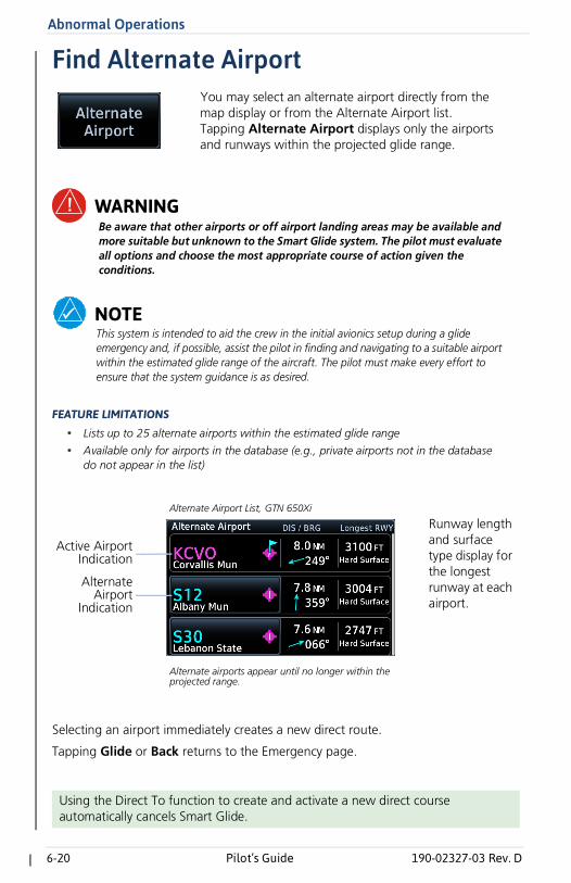
Find Alternate Airport
WARNINGBe aware that other airports or off airport landing areas may be available and more suitable but unknown to the Smart Glide system. The pilot must evaluate all options and choose the most appropriate course of action given the conditions.
NOTEThis system is intended to aid the crew in the initial avionics setup during a glide emergency and, if possible, assist the pilot in finding and navigating to a suitable airport within the estimated glide range of the aircraft. The pilot must make every effort to ensure that the system guidance is as desired.
FEATURE LIMITATIONS
• Lists up to 25 alternate airports within the estimated glide range
• Available only for airports in the database (e.g., private airports not in the databasedo not appear in the list)
Selecting an airport immediately creates a new direct route.
Tapping Glide or Back returns to the Emergency page.
Using the Direct To function to create and activate a new direct course automatically cancels Smart Glide.
You may select an alternate airport directly from the map display or from the Alternate Airport list. Tapping Alternate Airport displays only the airports and runways within the projected glide range.
Active Airport Indication
Alternate Airport List, GTN 650Xi
Alternate airports appear until no longer within the projected range.
AlternateAirport
Indication
Runway length and surface type display for the longest runway at each airport.
Abnormal Operations
190-02327-03 Rev. D Pilot’s Guide 6-21
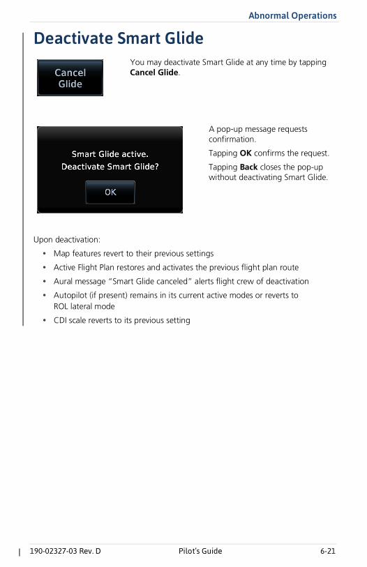
Deactivate Smart Glide
Upon deactivation:
• Map features revert to their previous settings
• Active Flight Plan restores and activates the previous flight plan route
• Aural message “Smart Glide canceled” alerts flight crew of deactivation
• Autopilot (if present) remains in its current active modes or reverts toROL lateral mode
• CDI scale reverts to its previous setting
You may deactivate Smart Glide at any time by tapping Cancel Glide.
A pop-up message requests confirmation.
Tapping OK confirms the request.
Tapping Back closes the pop-up without deactivating Smart Glide.
6-22 Pilot’s Guide 190-02327-03 Rev. D
Abnormal Operations
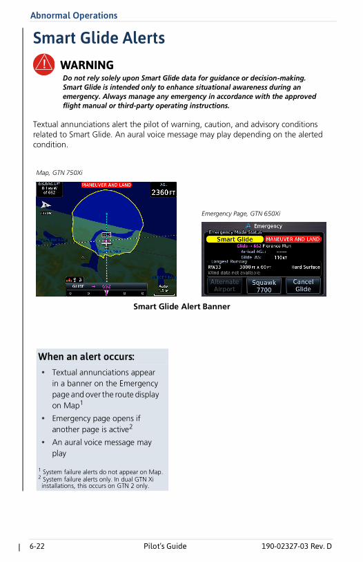
Smart Glide AlertsWARNINGDo not rely solely upon Smart Glide data for guidance or decision-making. Smart Glide is intended only to enhance situational awareness during an emergency. Always manage any emergency in accordance with the approved flight manual or third-party operating instructions.
Textual annunciations alert the pilot of warning, caution, and advisory conditions related to Smart Glide. An aural voice message may play depending on the alerted condition.
Smart Glide Alert Banner
Map, GTN 750Xi
Emergency Page, GTN 650Xi
When an alert occurs:• Textual annunciations appear
in a banner on the Emergencypage and over the route displayon Map1
• Emergency page opens ifanother page is active2
• An aural voice message mayplay
1 System failure alerts do not appear on Map.2 System failure alerts only. In dual GTN Xi installations, this occurs on GTN 2 only.
Abnormal Operations
190-02327-03 Rev. D Pilot’s Guide 6-23
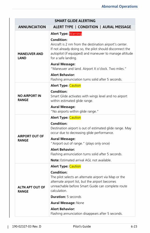
SMART GLIDE ALERTING
ANNUNCIATION ALERT TYPE | CONDITION | AURAL MESSAGE
MANEUVER AND LAND
Alert Type: Warning
Condition: Aircraft is 2 nm from the destination airport’s center.If not already doing so, the pilot should disconnect the autopilot (if equipped) and maneuver to manage altitude for a safe landing.
Aural Message: “Maneuver and land. Airport X o’clock. Two miles.”
Alert Behavior: Flashing annunciation turns solid after 5 seconds.
NO AIRPORT IN RANGE
Alert Type: Caution
Condition: Smart Glide activates with wings level and no airport within estimated glide range.
Aural Message: “No airports within glide range.”
AIRPORT OUT OF RANGE
Alert Type: Caution
Condition: Destination airport is out of estimated glide range. May occur due to decreasing glide performance.
Aural Message: “Airport out of range.” (plays only once)
Alert Behavior: Flashing annunciation turns solid after 5 seconds.
Note: Estimated arrival AGL not available.
ALTN APT OUT OF RANGE
Alert Type: Caution
Condition: The pilot selects an alternate airport via Map or the alternate airport list, but the airport becomes unreachable before Smart Guide can complete route calculation.
Duration: 5 seconds
Aural Message: None
Alert Behavior: Flashing annunciation disappears after 5 seconds.
6-24 Pilot’s Guide 190-02327-03 Rev. D
Abnormal Operations
None
Alert Type: Caution
Condition: Smart Glide is active within 2 nm of the destination airport, the autopilot is engaged, and there is not enough altitude for the system to safely make a full circle descent with 2,000 ft remaining. Disengage autopilot to manage energy.
Aural Message: “Disconnect autopilot.” (plays 10 seconds after arriving within 2 nm of destination airport)
CALCULATING ROUTE
Alert Type: Advisory
Condition: System is calculating the glide route to a suitable destination airport. Occurs during the following:
• Smart Glide activation
• Selection of an alternate destination (pilot override)
• When the CDI exceeds half of full-scale deviation
Aural Message: None
Note: Estimated arrival AGL not available until route calculation is complete.
ACTIVE
Alert Type: Advisory
Condition: Destination airport within range. Follow the displayed GPS route.
Aural Messages:
• “Airport X o’clock. More than thirty miles.”• “Airport X o’clock. X miles.”• “Airport X o’clock. X and a half miles.”• “Airport X o’clock. One mile.”• “Airport X o’clock. Less than one mile.”
SMART GLIDE ALERTING
ANNUNCIATION ALERT TYPE | CONDITION | AURAL MESSAGE
Abnormal Operations
190-02327-03 Rev. D Pilot’s Guide 6-25
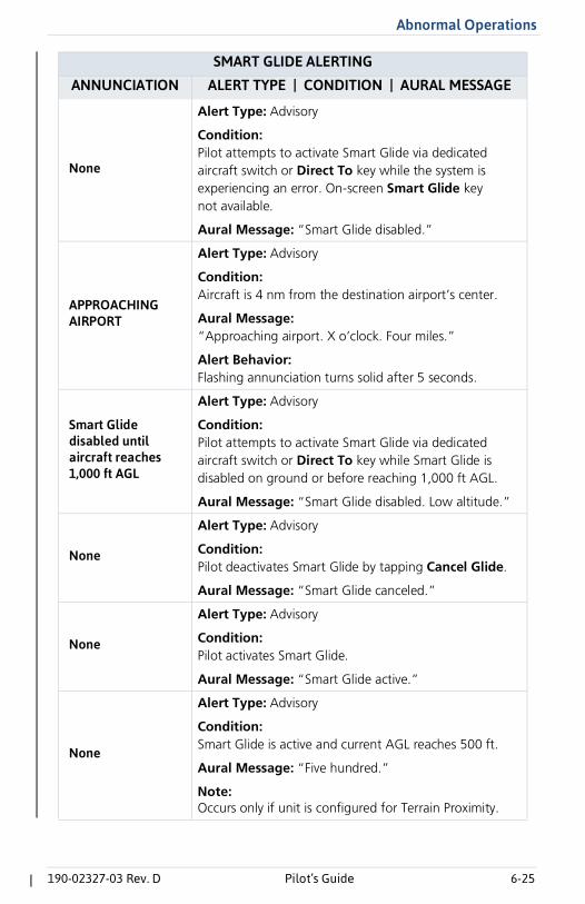
None
Alert Type: Advisory
Condition: Pilot attempts to activate Smart Glide via dedicated aircraft switch or Direct To key while the system is experiencing an error. On-screen Smart Glide key not available.
Aural Message: “Smart Glide disabled.”
APPROACHING AIRPORT
Alert Type: Advisory
Condition: Aircraft is 4 nm from the destination airport’s center.
Aural Message: “Approaching airport. X o’clock. Four miles.”
Alert Behavior: Flashing annunciation turns solid after 5 seconds.
Smart Glide disabled until aircraft reaches 1,000 ft AGL
Alert Type: Advisory
Condition: Pilot attempts to activate Smart Glide via dedicated aircraft switch or Direct To key while Smart Glide is disabled on ground or before reaching 1,000 ft AGL.
Aural Message: “Smart Glide disabled. Low altitude.”
None
Alert Type: Advisory
Condition: Pilot deactivates Smart Glide by tapping Cancel Glide.
Aural Message: “Smart Glide canceled.”
None
Alert Type: Advisory
Condition: Pilot activates Smart Glide.
Aural Message: “Smart Glide active.”
None
Alert Type: Advisory
Condition: Smart Glide is active and current AGL reaches 500 ft.
Aural Message: “Five hundred.”
Note: Occurs only if unit is configured for Terrain Proximity.
SMART GLIDE ALERTING
ANNUNCIATION ALERT TYPE | CONDITION | AURAL MESSAGE
6-26 Pilot’s Guide 190-02327-03 Rev. D
Abnormal Operations
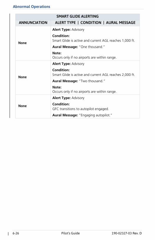
None
Alert Type: Advisory
Condition: Smart Glide is active and current AGL reaches 1,000 ft.
Aural Message: “One thousand.”
Note: Occurs only if no airports are within range.
None
Alert Type: Advisory
Condition: Smart Glide is active and current AGL reaches 2,000 ft.
Aural Message: “Two thousand.”
Note: Occurs only if no airports are within range.
None
Alert Type: Advisory
Condition: GFC transitions to autopilot engaged.
Aural Message: “Engaging autopilot.”
SMART GLIDE ALERTING
ANNUNCIATION ALERT TYPE | CONDITION | AURAL MESSAGE
Abnormal Operations
190-02327-03 Rev. D Pilot’s Guide 6-27
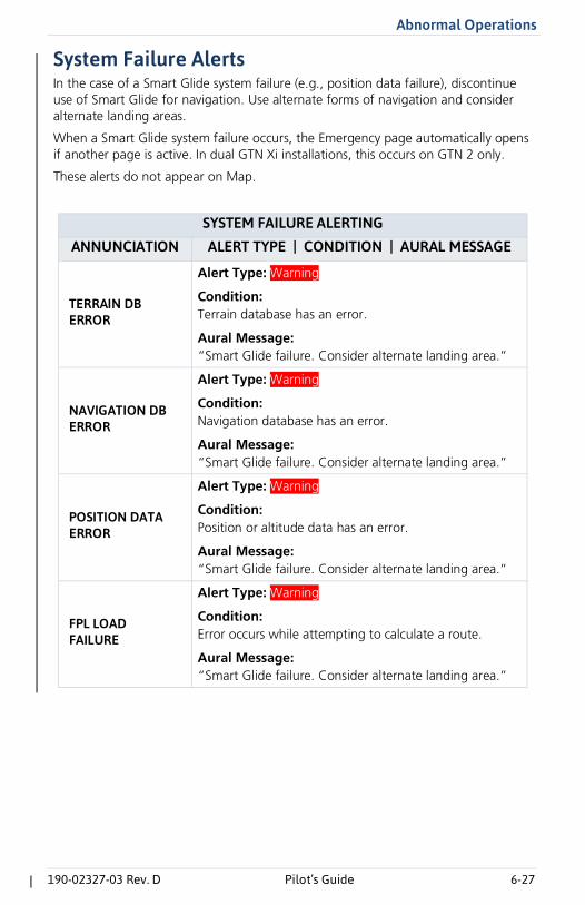
System Failure AlertsIn the case of a Smart Glide system failure (e.g., position data failure), discontinue use of Smart Glide for navigation. Use alternate forms of navigation and consider alternate landing areas.
When a Smart Glide system failure occurs, the Emergency page automatically opens if another page is active. In dual GTN Xi installations, this occurs on GTN 2 only.
These alerts do not appear on Map.
SYSTEM FAILURE ALERTING
ANNUNCIATION ALERT TYPE | CONDITION | AURAL MESSAGE
TERRAIN DB ERROR
Alert Type: Warning
Condition: Terrain database has an error.
Aural Message: “Smart Glide failure. Consider alternate landing area.”
NAVIGATION DB ERROR
Alert Type: Warning
Condition: Navigation database has an error.
Aural Message: “Smart Glide failure. Consider alternate landing area.”
POSITION DATA ERROR
Alert Type: Warning
Condition: Position or altitude data has an error.
Aural Message: “Smart Glide failure. Consider alternate landing area.”
FPL LOAD FAILURE
Alert Type: Warning
Condition: Error occurs while attempting to calculate a route.
Aural Message: “Smart Glide failure. Consider alternate landing area.”
6-28 Pilot’s Guide 190-02327-03 Rev. D
Abnormal Operations
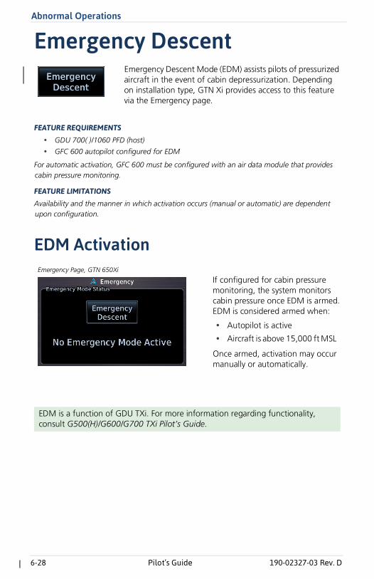
Emergency Descent
FEATURE REQUIREMENTS
• GDU 700( )/1060 PFD (host)
• GFC 600 autopilot configured for EDM
For automatic activation, GFC 600 must be configured with an air data module that provides cabin pressure monitoring.
FEATURE LIMITATIONS
Availability and the manner in which activation occurs (manual or automatic) are dependent upon configuration.
EDM Activation
EDM is a function of GDU TXi. For more information regarding functionality, consult G500(H)/G600/G700 TXi Pilot’s Guide.
Emergency Descent Mode (EDM) assists pilots of pressurized aircraft in the event of cabin depressurization. Depending on installation type, GTN Xi provides access to this feature via the Emergency page.
If configured for cabin pressure monitoring, the system monitors cabin pressure once EDM is armed. EDM is considered armed when:
• Autopilot is active
• Aircraft is above 15,000 ft MSL
Once armed, activation may occur manually or automatically.
Emergency Page, GTN 650Xi
Messages
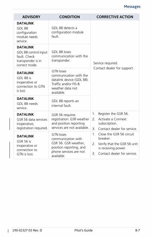
190-02327-03 Rev. D Pilot’s Guide 8-7
DATALINKGDL 88 configuration module needs service.
GDL 88 detects a configuration module fault.
Service required. Contact dealer for support.
DATALINKGDL 88 control input fault. Check transponder is in correct mode.
GDL 88 loses communication with the transponder.
DATALINKGDL 88 is inoperative or connection to GTN is lost.
GTN loses communication with the datalink device (GDL 88). Traffic and/or FIS-B weather data not available.
DATALINKGDL 88 needs service.
GDL 88 reports an internal fault.
DATALINKGSR 56 data services inoperative; registration required.
GSR 56 requires registration. GSR weather and position reporting services are not available.
1. Register the GSR 56.
2. Activate a Connextsubscription.
3. Contact dealer for service.
DATALINKGSR 56 is inoperative or connection to GTN is lost.
GTN loses communication with GSR 56. GSR weather, position reporting, and phone services are not available.
1. Close the GSR 56 circuitbreaker.
2. Verify that the GSR 56 unitis receiving power.
3. Contact dealer for service.
ADVISORY CONDITION CORRECTIVE ACTION
Messages
190-02327-03 Rev. D Pilot’s Guide 8-15
Smart Glide AdvisoriesThe unit automatically inhibits Smart Glide when the required conditions are not met.
ADVISORY CONDITION CORRECTIVE ACTION
REMOTE KEY STUCKEngage/Disengage Smart Glide key is stuck.
System detects the indicated remote key is depressed for at least 30 seconds. It will now ignore this input.
Push the indicated key again.If it remains stuck, contact dealer for service.
SMART GLIDEDisabled. Activation manually disabled by pilot.
Pilot disables Smart Glide activation by toggling the Smart Glide Activation key to Disabled.
Re-enable Smart Glide activation. From the Home page, tap Emergency > Menu, and toggle the Smart Glide Activation key to Enabled.
SMART GLIDEDisabled. Erroneous activation detected. May be re-enabled via Emergency page menu.
System disables Smart Glide activation because the feature exceeded the maximum number of activations allowed within a one minute period. System allows up to three activations per minute.
SMART GLIDEDisabled. System initializing.
System disables Smart Glide activation for 40 seconds after unit power up.
Wait 40 seconds for system initialization to complete, then re-attempt activation.
SMART GLIDEUnavailable above 11,000M/36,000FT.1
Aircraft altitude is above the indicated MSL.
Descend below 11,000 m/36,000 ft and attempt to activate Smart Glide.
8-16 Pilot’s Guide 190-02327-03 Rev. D
Messages
1 Actual units dependent upon configuration.
SMART GLIDEUnavailable. AHRS roll angle lost.
GTN Xi is not receiving a valid roll angle from the AHRS source.
Contact dealer for service.
SMART GLIDEUnavailable. Barometric altitude lost.
GTN Xi is not receiving valid barometric altitude.
SMART GLIDEUnavailable. Crossfill Error.
A crossfill error prevents Smart Glide from functioning properly.
SMART GLIDEUnavailable. Magnetic heading lost.
GTN Xi is not receiving a valid heading from AHRS source.
SMART GLIDEUnavailable. True airspeed lost.
GTN Xi is not receiving valid true airspeed from ADC source.
ADVISORY CONDITION CORRECTIVE ACTION

190-02327-11 Rev. A