GTD-5000 Instruction Manual - · PDF fileGTD5000 Instruction Manual PAGE 6 of 54 Rev1,...
55
Design, Develop, Manufacture, Install and Maintenance Service for Gas Leak Alarm GTD-5000 Instruction Manual Revision: 1 Copyright⒞GASTRON, Co., LTD. All rights reserved. For proper use, please read this manual thoroughly prior to operation
Transcript of GTD-5000 Instruction Manual - · PDF fileGTD5000 Instruction Manual PAGE 6 of 54 Rev1,...
Design, Develop, Manufacture, Install and Maintenance Service for Gas Leak Alarm
GTD-5000
Instruction Manual
Revision: 1
Copyright⒞GASTRON, Co., LTD. All rights reserved.
For proper use, please read this manual thoroughly prior to operation

GTD5000 Instruction Manual
PAGE 2 of 54 Rev1, 2013.5.2
Thank you for purchasing our GASTRON’s product.
Gastron is a specialized company in producing gas detector and gas monitoring system. We
have been recognized by customers for our best quality products and excellence in easy-to-use
design. We are striving to provide the suitable product that fits customer’s needs, and
continuously put every effort to develop better gas detector to satisfy customer’s requirements.
From now on, we will be your reliable partner to shed a bright light on your concern about gas
detector. Please contact us if you have any question. You can obtain best solution from us with
great satisfaction.
This instruction manual describes how to operate GTD5000 gas detector for proper use. It also
simply explains how to maintain and repair the GTD5000. Please keep this manual safe after
reading it thoroughly, because this manual will be of great help when you have any trouble or
question during you are using the product.
If you have any problem in using our product, please contact us as follows:
Address :
18-8, Dogeumdanji 1-gil (Palgok 2-dong), Sangrok-gu, Ansan-si, Gyeonggi-do, Korea
Tel : 031-490-0800
Fax : 031-490-0801
URL : www.gastron.com
e-mail : [email protected]
Note
• You are recommended that your gas detector be inspected and calibrated
with calibrating gas prior to using it.
• Without getting calibrated, the device might be malfunctioned due to
sensor aging problem.
• In case of replacing this device, qualified technician of gas detector should
perform the replacement to make sure that this procedure is done in the
safest way possible.
• For details about maintenance and calibration of gas detector, please
contact our technical department, send us email or visit our web site.

GTD5000 Instruction Manual
PAGE 3 of 54 Rev1, 2013.5.2
This page intentionally left blank
GTD5000 Instruction Manual
PAGE 4 of 54 Rev1, 2013.5.2
TABLE OF CONTENTS
1. Introduction ..................................................................................................................................................................... 6
2. Structure ............................................................................................................................................................................ 6
3. Specification .................................................................................................................................................................... 7
4. Name and Functional Description of Components ....................................................................................... 8
4.1. Composing Elements ......................................................................................................................................... 8
4.2. Disassembly Diagram ......................................................................................................................................... 9
4.3. Functional Description of Components ..................................................................................................... 9
4.4. Front Viwe of LCD Layout .............................................................................................................................. 11
5. Menu Table .................................................................................................................................................................... 12
6. How to Operate ........................................................................................................................................................... 15
6.1. Check Power Wiring ......................................................................................................................................... 15
6.2. Power On ............................................................................................................................................................... 15
6.3. Gas Measuring State (Measuring Mode) ................................................................................................ 16
6.4. Environment Configuration(Configuration Mode) .............................................................................. 17
6.5. Program setting .................................................................................................................................................. 19
6.6. Zero Calibration .................................................................................................................................................. 20
6.7. Span Calibration ................................................................................................................................................. 21
6.8. Alarm Data Setting (Alarm mode) ............................................................................................................. 22
6.9. Current Time Reading and Setting ............................................................................................................ 26
6.10. Checking and Setting Sensor Data ......................................................................................................... 27
6.11. Test Function Setting ..................................................................................................................................... 29
6.12. Flow Setting ....................................................................................................................................................... 31
6.13. Maintenance Mode Setting ........................................................................................................................ 32
6.14. Network Setting ............................................................................................................................................... 35
7. Error & Warning Message (Troubleshooting) ................................................................................................ 37
7.1. Error Code ............................................................................................................................................................. 37
7.2. Warning Code ..................................................................................................................................................... 37
8. Communication Interface ........................................................................................................................................ 38
8.1. 4~20mA Output Current ................................................................................................................................ 38
8.2. 485 MODBUS Interface ................................................................................................................................... 38
GTD5000 Instruction Manual
PAGE 5 of 54 Rev1, 2013.5.2
8.2.1. RS485 Communication Configuration ......................................................................................... 38
8.2.2. Address Architecture ........................................................................................................................... 38
8.3. MODBUS/TCP Interface .................................................................................................................................. 39
8.4. Terminal Board Connector Layout ............................................................................................................. 42
8.5. Terminal Board Connector Detailed Description ................................................................................. 43
8.5.1. Power & Output Signal Terminal(CN1) ....................................................................................... 43
8.5.2. RS485 & Relay Contact Terminal(CN3) ....................................................................................... 43
9. Connector Wiring Diagram..................................................................................................................................... 44
9.1. Power and 4-20mA Signal Connection ................................................................................................... 44
9.1.1. Power and 4~20mA Source Connection .................................................................................... 44
9.1.2. Power and 4~20mA Sink Connection ......................................................................................... 44
9.2. Alarm signal connection ................................................................................................................................. 45
9.3. RS-485 Communication Signal Connection ........................................................................................... 45
9.4. Ethernet Signal Connection .......................................................................................................................... 46
9.4.1. Connection in case of using PoE ................................................................................................... 46
9.4.2. PoE Connection in case of using Pyrolyzer option ............................................................... 46
9.5. How to Connect the Gas Detector to Control Units ......................................................................... 47
10. Appearance and Dimensions ................................................................................................................................. 48
10.1. GTD-5000 Appearance and Dimensions .............................................................................................. 48
10.2. GTD-5000 & PY-1000 Appearance and Dimensions ...................................................................... 49
10.3. GTD-5000 & PY-2000 Appearance and Dimensions ...................................................................... 50
11. Precautions prior to Installation ........................................................................................................................... 51
11.1. Selection of installation site (according to Industrial Safety and Health Regulations) 51
11.2. Selection of installation site (according to High Pressure Gas Safety Control Act) ...... 51
11.3. Things to keep in mind when installing ............................................................................................... 52
11.4. Cable Wiring ...................................................................................................................................................... 52
12. Ordering Information ................................................................................................................................................ 53
13. Revision History ........................................................................................................................................................... 55
GTD5000 Instruction Manual
PAGE 6 of 54 Rev1, 2013.5.2
1. Introduction
The GTD-5000 is a proven gas detector developed to prevent serious accidents which might be caused by
unexpected gas leaks by detecting a variety of gases in hazardous areas such as industrial plants, gas
storage facilities and factories in the process of producing or consuming flammable gases and toxic gases.
When the GTD-5000, sampling-type gas detector, is installed in locations that may have gas leaks, it will
continuously monitor the ambient level of gas and display the measured value of gas concentration on its
integrated LCD. Additionally, it could generate DC 4-20mA standard output, RS-485 communication signal,
Power over Ethernet(PoE) communication signal, and relay contact signal on occurrence of gas alarm.
For standard output of DC 4-20mA, output receiver can support up to 2,500 meters distance away from
gas detector to get output signal (only if CVVS or CVVSB 1.5sq↑ shield cable is used). A communication
signal of RS-485 can be transmitted up to 1,000 meters (only if RS0485 dedicated line is used). A
communication signal of PoE(Power over Ethernet) can be transmitted up to 100 meters.
2. Structure
The case of GTD-5000 is made of steel.
This product can be installed in dangerous area that may have gas leakage, especially for flammable
and/or toxic gases. The integrated 4-digit LCD indicates current gas leak status on the spot. The internal
structure of the product mainly consists of five sub-parts as follows: (1) LCD that displays the measured
value of gas, (2) main controller that measures and controls a gas concentration and flow rate, (3) output
current (DC 4-20mA) or RS-485 communication signal, (4) PoE communication signal, and (5) terminal
part that delivers alarm signal to outside of the product. A sensor is a removable cartridge type, so that it
can be easily detached and replaced.

GTD5000 Instruction Manual
PAGE 7 of 54 Rev1, 2013.5.2
3. Specification
Items Specifications
Measuring type Auto Sampling type
Measuring value display LCD display of measured value(4-digit), alarm and flow rate etc.
Enclosure Non-explosion proof type
Detectible Gas Toxic gas, Oxygen, Flammable gas
Measuring Method Electro-chemical, catalytic combustion, and semiconductor type
Flow rate Maximum 0 ~ 1,000 ml/min & minimum normal 300~500ml/min
Gas sample line Within 40m ( 1/4" Tube )
Micro air pump AC 6V, Max 1.8ℓ/min, 350g(Diaphragm Pump)
Measuring Range 0 – 9,999 Adjustable(refer to Ordering Information)
Accuracy ≤ ±3% / Full Range
Zero Drift ≤2% / Full Range
Operation Temperature -20 to 50 ℃
Operation Humidity 5 to 99% RH (Non-condensing)
Inlet tube
(Sample gas vent / inlet)
1/4" Teflon Tube
Output signal
(Measuring Signal Output)
4 - 20mA DC / RS-485 Modbus / PoE(Power over Ethernet)
Relay contact point current
(Alarm Relay Contact)
SPST, Load: AC 250V / 1A (Alarm1,Alarm2,Trouble)
Power supply
Standard :18 ~31V DC (24V DC normal) / 280mA Max.
18 ~31V DC (24V DC normal) / 280mA Max. Pyrolyzer(NOTE1) : 18 ~31V DC (24V DC normal) / 520mA Max.
18 ~31V DC (24V DC normal) / 520mA Max. PoE(NOTE2) : 48V DC ±10% / 200mA Max.
48V DC ±10% / 200mA Max. ( NOTE1 ) Wiring
(Signal Cable Connection)
Standard type : (CVVS or CVVSB 1.5sq↑)+Shield
PoE type : RJ45 Ethernet Cable
Cable Connection Length
4 - 20mA DC Signal : 2500m
RS-485 Modbus Signal : 1000m
PoE(Power over Ethernet) : 100m
Mounting type Wall mount
Weight
Standard type : 1.75kg
GTD5000 &PY-1000 : 4.05kg
GTD5000 &PY-2000 : 4.75kg
Dimensions
Standard type : 70(W) ×144(H) × 160(D) mm
Pyrolyzer type(PY-1000) : 70(W) ×242.5(H) × 160(D) mm
Pyrolyzer type(PY-2000) : 70(W) ×267.5(H) ×200(D) mm
Approval CE ( EN50270:1999 )
[Table1.Gas detector Specifications]
※NOTE1: Current consumed by Polyzer(PY1000, PY2000) Unit
※NOTE2: DC 24V should be supplied if you want to use Pyrolyzer in case of using PoE power (refer to 9.4.2)
GTD5000 Instruction Manual
PAGE 8 of 54 Rev1, 2013.5.2
4. Name and Functional Description of Components
4.1. Composing Elements
POWER TROUBLE ALARM1 ALARM2
CO
3
4
8
9
11
10
5 6 7
12
13
15
16
14
17
1 2
14 15 16
OU
T
CAB
LE
IN
18
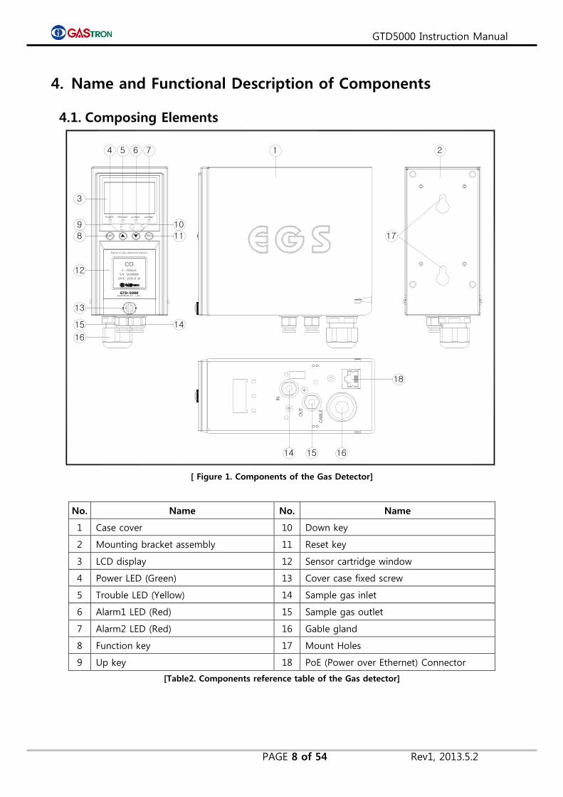
[ Figure 1. Components of the Gas Detector]
No. Name No. Name
1 Case cover 10 Down key
2 Mounting bracket assembly 11 Reset key
3 LCD display 12 Sensor cartridge window
4 Power LED (Green) 13 Cover case fixed screw
5 Trouble LED (Yellow) 14 Sample gas inlet
6 Alarm1 LED (Red) 15 Sample gas outlet
7 Alarm2 LED (Red) 16 Gable gland
8 Function key 17 Mount Holes
9 Up key 18 PoE (Power over Ethernet) Connector
[Table2. Components reference table of the Gas detector]

GTD5000 Instruction Manual
PAGE 9 of 54 Rev1, 2013.5.2
4.2. Disassembly Diagram
[ Figure 2. Disassembly Diagram of the Gas detector]
4.3. Functional Description of Components
1) Case cover
It protects sensor and internal part such as PCB board and pump against environmental
variations and shocks.
2) Mounting bracket assembly
It is a part used for fixing a case, including mounting hole, cable gland and in/output of
gas etc.
3) LCD Display
It is used for displaying a value of gas concentration measured by sensor. It also indicates
a setting mode with use of numbers and icons, when the user sets parameter. (For
detailed description about icon, refer to 4.4 Front panel LCD layout)
4) Power LED (Green)
This Power LED is turned on when power is successfully supplied. (DC18~31V).
5) Trouble LED (Yellow)
This Trouble LED is turned on when a device is recognized as malfunctioned, for example,
something wrong with sensor or flow rate. At the same time, trouble relay contact signal
output is generated toward outside, to indicate troubled condition.
6) Alarm1 LED (Red)
This Alarm1 LED is turned on, when the measured value of gas concentration exceeds the
preset value of Alarm1 level. In this case, relay contact signal output is produced toward
outside as well.
(Alarm1 level can be set arbitrarily in alarm setting mode)
GTD5000 Instruction Manual
PAGE 10 of 54 Rev1, 2013.5.2
7) Alarm2 LED (Red)
This Alarm2 LED is turned on, when the measured value of gas concentration exceeds the
preset value of Alarm2 level. In this case, relay contact signal output is also produced
toward outside. (Alarm2 level can be set arbitrarily in alarm setting mode)
8) Function key
This key is used for changing and setting the mode. In measuring state, if you press and
hold FUNC key for 2 seconds or more, the device enters a menu mode of function
setting. (configuration, program, calibration, alarm and time etc.)
9) Up key
It is a key to increase a setting value in function setting mode.
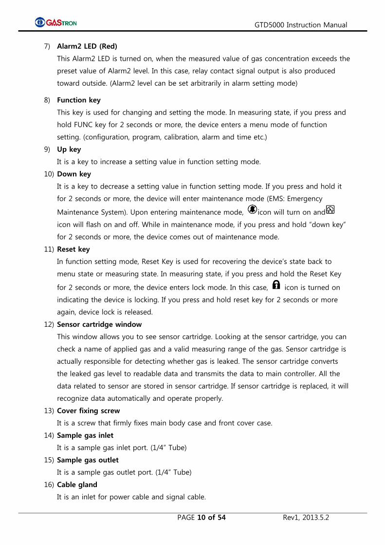
10) Down key
It is a key to decrease a setting value in function setting mode. If you press and hold it
for 2 seconds or more, the device will enter maintenance mode (EMS: Emergency
Maintenance System). Upon entering maintenance mode, icon will turn on and
icon will flash on and off. While in maintenance mode, if you press and hold “down key”
for 2 seconds or more, the device comes out of maintenance mode.
11) Reset key
In function setting mode, Reset Key is used for recovering the device’s state back to
menu state or measuring state. In measuring state, if you press and hold the Reset Key
for 2 seconds or more, the device enters lock mode. In this case, icon is turned on
indicating the device is locking. If you press and hold reset key for 2 seconds or more
again, device lock is released.
12) Sensor cartridge window
This window allows you to see sensor cartridge. Looking at the sensor cartridge, you can
check a name of applied gas and a valid measuring range of the gas. Sensor cartridge is
actually responsible for detecting whether gas is leaked. The sensor cartridge converts
the leaked gas level to readable data and transmits the data to main controller. All the
data related to sensor are stored in sensor cartridge. If sensor cartridge is replaced, it will
recognize data automatically and operate properly.
13) Cover fixing screw
It is a screw that firmly fixes main body case and front cover case.
14) Sample gas inlet
It is a sample gas inlet port. (1/4” Tube)
15) Sample gas outlet
It is a sample gas outlet port. (1/4” Tube)
16) Cable gland
It is an inlet for power cable and signal cable.
GTD5000 Instruction Manual
PAGE 11 of 54 Rev1, 2013.5.2
17) Mount holes
These holes are used for fixing the gas detector to wall or other flat surface.
18) PoE(Power Over Ethernet) Connector
It is a RJ45 ethernet connector supporting PoE communication.
4.4. Front Viwe of LCD Layout
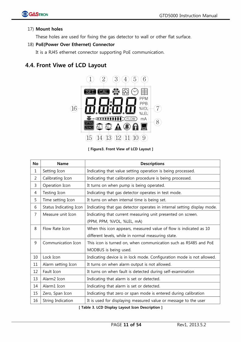
[ Figure3. Front View of LCD Layout ]
No Name Descriptions
1 Setting Icon Indicating that value setting operation is being processed.
2 Calibrating Icon Indicating that calibration procedure is being processed.
3 Operation Icon It turns on when pump is being operated.
4 Testing Icon Indicating that gas detector operates in test mode.
5 Time setting Icon It turns on when internal time is being set.
6 Status Indicating Icon Indicating that gas detector operates in internal setting display mode.
7 Measure unit Icon Indicating that current measuring unit presented on screen.
(PPM, PPM, %VOL, %LEL, mA)
8 Flow Rate Icon When this icon appears, measured value of flow is indicated as 10
different levels, while in normal measuring state.
9 Communication Icon This icon is turned on, when communication such as RS485 and PoE
MODBUS is being used.
10 Lock Icon Indicating device is in lock mode. Configuration mode is not allowed.
11 Alarm setting Icon It turns on when alarm output is not allowed.
12 Fault Icon It turns on when fault is detected during self-examination
13 Alarm2 Icon Indicating that alarm is set or detected.
14 Alarm1 Icon Indicating that alarm is set or detected.
15 Zero, Span Icon Indicating that zero or span mode is entered during calibration
16 String Indication It is used for displaying measured value or message to the user
[ Table 3. LCD Display Layout Icon Description ]
AL2
PPBPPM
mA
CALSET
FLOW
AL1ZERO
SPAN
1 2 3 4 5 6
7
9101112131415
16
8

GTD5000 Instruction Manual
PAGE 12 of 54 Rev1, 2013.5.2
5. Menu Table
Level1 Level2 Level3 Default
CONFIG-
URATION
MODE
(Conf)
Add(Address) OFF,1~64 (Communication address for 485 Modbus) OFF
PSWd(Password) 0~99 (setting password) 00
C-tm(Calibration Time) OFF, 1~12(Setting calibration period in month) OFF
SUPr(Suppression) OFF, 1~50 (measured gas suppression rate, operates in 20%
of full range) 03%
PyrO(Pyrolyzer) On ,OFF (set if power current consumed by Pyrolyzer is used) OFF
U-01(Version) Firmware version number -
End - -
PROGR-
AM MODE
(Prgm)
UnIt PPM, PPB, %VOL,, %LEL (Setting measuring unit) %LEL
dP-S(Decimal Point) 1000, 100.0, 10.00, 1.000 (Setting measurement accuracy) 100
H-SL(High Scale) 1~9999 (Setting Full Range(High Scale) of measurement) 100
End - -
CALIBRA-
TION
MODE
(CALb)
ZERO no , YES no
0 PPM Zero current measured value -
Wait(Wait) - -
GOOd(Good) Good, Fail -
0 PPM Measured value after completing zero calibration -
SPAN no , YES no
50 PPM Setting standard value of gas for SPAN calibration 50%/F.R.
45 PPM Current measured value
Wait(Wait)
GOOd(Good) Good, Fail -
50 PPM Measured value after completing Span Calibration -
End - -
ALARM
MODE
(ALAm)
LACH(Latching) On , OFF OFF
AL-1(Alarm 1) Setting 90% of 1~Full range. 20%/F.R.
1H/1L(Alarm direction) H: High level Alarm / L: Low level Alarm 1H
1H00/1L00(Dead band) 0~10%/Full Range 1H00
AL1t(Alarm1 time) 0~30sec(Alarm delay time) 1sec
A1rL(Alarm1 Relay) On , OFF(setting for relay use) On
A1br(Alarm1 blinking) On , OFF(setting for relay blinking use) OFF
AL-2(Alarm 2) Setting 90% of 1~Full range 40%/F.S.
2H/2L(Alarm direction) H: High level Alarm / L: Low level Alarm 2H
2H00/2L00(Dead band) 0~10%/Full Range 2H00
AL2t(Alarm2 time) 0~30sec(Alarm delay time) 1sec
A2rL(Alarm2 Relay) On , OFF(setting for relay use) On
A2br(Alarm2 blinking) On , OFF(setting for relay blinking use) OFF
End - -

GTD5000 Instruction Manual
PAGE 13 of 54 Rev1, 2013.5.2
Level1 Level2 Level3 Default
TIME
MODE
(timE)
CLOC(Clock) Current time reading mode
2012 Year
10-16 Month/Day
12:30 Hour/Minute
End - -
CLtm(Calibration time) Calibration date reading mode
2012 Year
10-16 Month/Day
12:30 Hour/Minute
End - -
S-tm(Sensor time) Sensor manufacturing date reading mode
2012 Year
10-16 Month/Day
12:30 Hour/Minute
End -
SENSOR
DATA
MODE
(S-dt)
Type(Sensor Type) ES(Explosive), tS(Toxic) tS
SdIr(Sensor direction) PLUS, MIus PLUS
gAIn(Gain) 1,2,4 (Sensor output gain ratio) g – 1
SOUt(Sensor output) Sensor output voltage(V) 0.000
SPWr(Sensor power) Sensor applied voltage(V) 0.000
tSEt(Sensor time set) No, YES(Sensor manufacturing date setting) no
End -
TEST
MODE
(tESt)
LCD Check LCD display state
trly(Test Relay) On , OFF (Set the alarm relay operation when testing) OFF
t-mA(Test mA output) On , OFF (Set the mA output when testing) OFF(4.0mA)
tgAS(Test gas) 0~Full(Gas concentration and output signal test) -
FOUt(Flow-rate output) 500/2.20 (indicates measured flow(ml)/Pump
voltage(V)) (Enables to adjust pump voltage by
pressing Up(△ and Down(▽) Key)
-
0.03/2.20 (indicates Pressure Sensor output voltage /
Pump voltage) (Enables to adjust pump voltage by
pressing Up(△) and Down(▽) Key) (unit: V)
-
PyrO(Pyrolyzer power) 0.400A(Check the current consumed by Pyrolyzer) 0.000A
tEmP(Temperature) 23 ℃(Indicate current temperature of Gas detector) Current temp.
FrAm(F-RAM) Good, Fail(FRAM test) 9ood
End -
FLOW
MODE
(FLOW)
AutO(Auto) YES(auto), no(manual) (setting type of flow control) YES
F-LE(Flow level) OFF(0)~1000 ml/min (setting flow rate level) 500ml/min
F-tm(Flow delay time) 15~60sec(Seting flow error latency time) 30sec
End -

GTD5000 Instruction Manual
PAGE 14 of 54 Rev1, 2013.5.2
Level1 Level2 Level3 Default
MAINTE-
NANCE
MODE
(m-t)
PoE On/OFF,Check operational state of PoE(Power over
Ethernet)
On/OFF
CSEn
(Cross sensitivity)
0.01~5.00(setting relative sensitivity value) 1.00
mUAL
(MeasurementValue)
0~Full Range(set output value for EMS)
Maintenance Mode(EMS:Emergency Maintenance System)
0(O2: 20.9)
ZbAn(Zero band) On , OFF(Zero band Suppression control setting) On
AUZO(Auto zero) On , OFF(Auto zerocontrol setting) On
Engm(Engineering
Mode)
On , OFF (Setting on/off whether Engineering Mode is
used or not)
OFF
Undr On , OFF(Setting on/off whether Under function is used) OFF
Odt
(Output delay time)
OFF, 1~60sec(setting delay time of measured data) OFF
OdU
(Outputdelay value)
OFF, 1~20%/F.S(setting a range of output signal delay) OFF
End -
NETWORK
MODE
(nEt)
IP
(IP address)
192(The first decimal number of IP address) 192
168(The second decimal number of IP address) 168
1(The third decimal number of IP address) 1
201(The fourth decimal number of IP address) 201
SnET
(Subnet Work mask)
255(The first decimal number of subnet mask) 255
255(The second decimal number of subnet mask) 255
255 (The third decimal number of subnet mask) 255
0 (The fourth decimal number of subnet mask) 0
Gw
(Gateway address)
192(The first decimal number of gateway) 192
168(The second decimal number of gateway) 168
1 (The third decimal number of gateway) 1
254 (The fourth decimal number of gateway) 254
Mac
6C (Company ID1) 6c
E9 (Company ID2) E9
83 (Company ID3) 83
00 (Unique Mac Address1 of gas detector) 00
00(Unique Mac Address2 of gas detector) 00
00(Unique Mac Address3 of gas detector) 00
End -
[ Table 4. Menu Table ]

GTD5000 Instruction Manual
PAGE 15 of 54 Rev1, 2013.5.2
6. How to Operate
6.1. Check Power Wiring
1) Check a connection between terminal PCB CN1’s operation power(+24V,GND) and 1-2 of J6
Jumper to make sure that the wiring is in good condition.
2) When PoE(Power over Ethernet) is used, CN4 (Ethernet port) should be plugged in. In this case, J6
Jumber must be connected via 2-3. (In case that pyrolzer option is chosen, PoE power will not be
sufficient, so that separate power of +24V needs to be connected for supplying enough power)
6.2. Power On
1) After making sure wiring and voltage of power, press Power swtich in front panel to power up.
2) You can see device’s operation as follows. First, power LED(Green) is turned on. Second, version
information (U-01) is displayed. Third,“LOAd” message is displayed, which indicates sensor data is
being loaded. Fourth, “WAIt”(Wait) and “Warm”(warming up) are displayed subsequently. Finally,
device’s state is transitioned to measuring state.
3) It will take about 30 seconds. While ‘WAIt’ is blinking, if you press RST(reset) key, message
‘Warm’ (warming up) will come up and the device enters measuring state.
If you turn on power switch, firmware version is shown for 2 seconds on
LCD (gas concentration displaying area)
“LOAd” message will be displayed for 5 seconds while sensor cartridge is
exchanging data with main controller at initial power-up stage. At this
moment, keys are disabled.
Upon completion of data exchanging between sensor cartridge and main
controller, “WAIt” will keep blinking for about 25 seconds during which
the self-examination is being performed.
If there is something faulty in this self-test, fault message will appear,
and fault alarm will be generated.
Warm” message will be displayed when sensor cartridge is warming-up.
~
Upon completion of sensor cartridge warming-up, countdown starts from
R5 to R1. After countdown finished, the device will go into measuring
mode.
Countdown will show up whenever the device enters measuring mode
from any other mode.

GTD5000 Instruction Manual
PAGE 16 of 54 Rev1, 2013.5.2
6.3. Gas Measuring State (Measuring Mode)
Gas concentration value sent by sensor cartriage is displayed on LCD with
numeric string. Currnet flow value is presented as bar graph.
If sensor cartridge gets faulty, an error code from “E-10” to “E-33” will be
blinking. At the same time, trouble LED(Yellow) is turned on.
(Regarding error code, please refer to 7. Error & Warring Message
(Troubleshooting))
If gas concentration value sent by sensor cartridge exceeds more than 10%
of preset high scale value, message “OUEr” will flash on and off every 0.5
second.
If gas concentration value exceeds preset alarm value, and alarm delay time
of corresponding alarm is elapsed, alarm goes off.
While alarm delay is being counted, alarm LED lamp will blink on and off
every 0.5 second. After alarm delay time is expired, alarm LED lamp remains
ON.
Alarm relay is turned on, after alarm delay time is expired.
In case of alarm latch type is ON mode, alarm condition and gas
concentration value remains(presented) in maximum level while alarm is
being operated. Even when gas concentration value drops down under the
alarm value, it doesn’t change. If you want to recover it, press “Reset” key.
In case of alarm latch type is OFF mode, alarm will operate automatically in
accordance with gas concentration.
GTD5000 Instruction Manual
PAGE 17 of 54 Rev1, 2013.5.2
6.4. Environment Configuration(Configuration Mode)
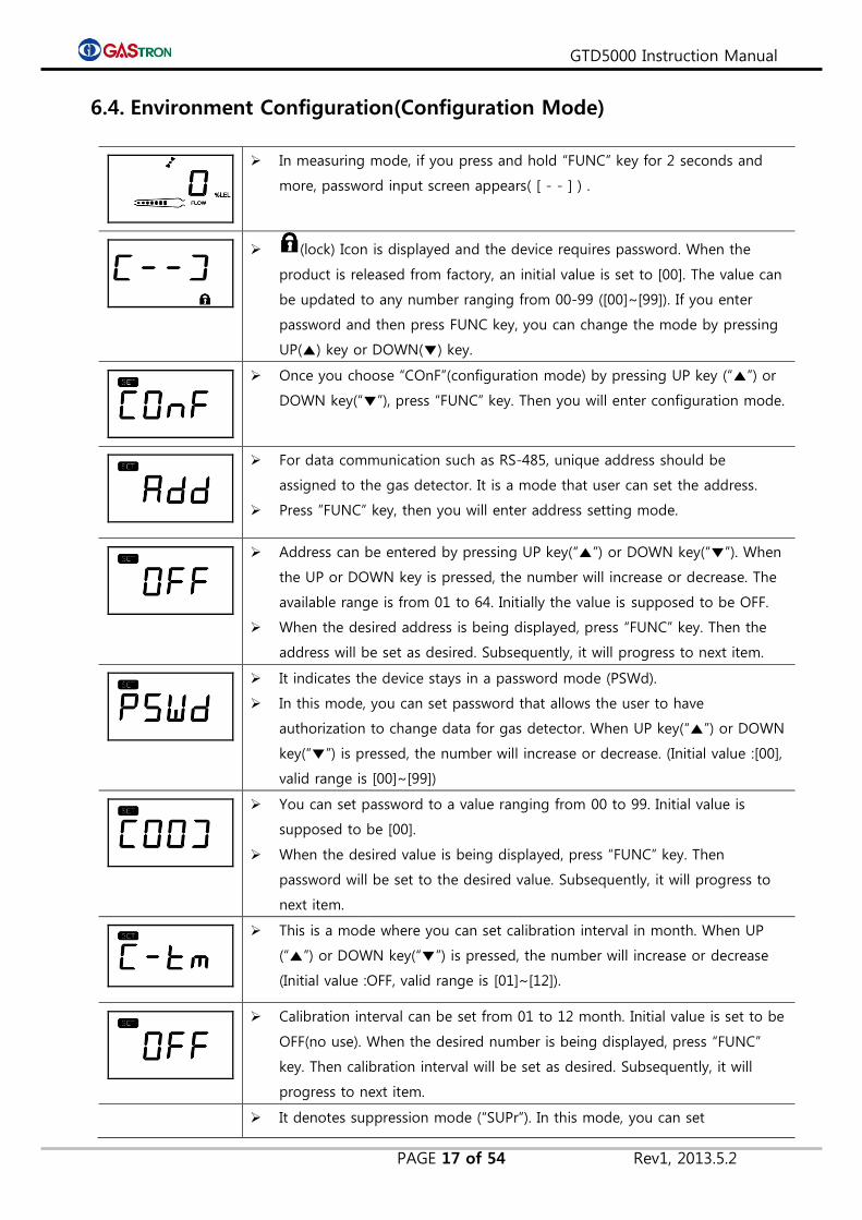
In measuring mode, if you press and hold “FUNC” key for 2 seconds and
more, password input screen appears( [ - - ] ) .
(lock) Icon is displayed and the device requires password. When the
product is released from factory, an initial value is set to [00]. The value can
be updated to any number ranging from 00-99 ([00]~[99]). If you enter
password and then press FUNC key, you can change the mode by pressing
UP(▲) key or DOWN(▼) key.
Once you choose “COnF”(configuration mode) by pressing UP key (“▲”) or
DOWN key(“▼”), press “FUNC” key. Then you will enter configuration mode.
For data communication such as RS-485, unique address should be
assigned to the gas detector. It is a mode that user can set the address.
Press ”FUNC” key, then you will enter address setting mode.
Address can be entered by pressing UP key(“▲”) or DOWN key(“▼”). When
the UP or DOWN key is pressed, the number will increase or decrease. The
available range is from 01 to 64. Initially the value is supposed to be OFF.
When the desired address is being displayed, press “FUNC” key. Then the
address will be set as desired. Subsequently, it will progress to next item.
It indicates the device stays in a password mode (PSWd).
In this mode, you can set password that allows the user to have
authorization to change data for gas detector. When UP key(“▲”) or DOWN
key(“▼”) is pressed, the number will increase or decrease. (Initial value :[00],
valid range is [00]~[99])
You can set password to a value ranging from 00 to 99. Initial value is
supposed to be [00].
When the desired value is being displayed, press “FUNC” key. Then
password will be set to the desired value. Subsequently, it will progress to
next item.
This is a mode where you can set calibration interval in month. When UP
(“▲”) or DOWN key(“▼”) is pressed, the number will increase or decrease
(Initial value :OFF, valid range is [01]~[12]).
Calibration interval can be set from 01 to 12 month. Initial value is set to be
OFF(no use). When the desired number is being displayed, press “FUNC”
key. Then calibration interval will be set as desired. Subsequently, it will
progress to next item.
It denotes suppression mode (“SUPr”). In this mode, you can set

GTD5000 Instruction Manual
PAGE 18 of 54 Rev1, 2013.5.2
suppression percentage of gas concentration, which speicifies gas
concentration is displayed with zero. When UP key(“▲”) or DOWN
key(“▼”) is pressed, the number of percentage will increase or decrease.
(Initial value :[03], valid range is [01]~[50])
You can set the value within 1%~20% of full range. Intial value is set to
03(3%).
When desired value of percentage is being displayed, press “FUNC” key.
Then suppression rate is set to be the desired percentage value.
Subsequently, it will progress to next item.
It is a mode in which you can select whether you are going to use pyrolyzer
or not. UP(“▲”) or DOWN key(“▼”) is used to set use or no-use.
In case that Pyrolyzer is used, select ON. Otherwise, select OFF. Once
choosing ON or OFF, press “FUNC”key. Then the desired setting is stored.
Subsequently, it will progress to next item.
It is a mode in which program version is viewed.
If you press “FUNC” key, then you can see “END” message subsequently.
When END is being displayed, press “FUNC” key. Then the device will go
back to menu mode.
It indicates the completion of setting or updating in configuration mode.
If you press “FUNC” key, it goes back to menu mode.
GTD5000 Instruction Manual
PAGE 19 of 54 Rev1, 2013.5.2
6.5. Program setting
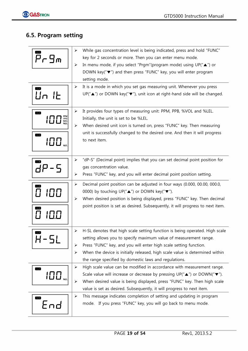
While gas concentration level is being indicated, press and hold “FUNC”
key for 2 seconds or more. Then you can enter menu mode.
In menu mode, if you select “Prgm”(program mode) using UP(“▲”) or
DOWN key(“▼”) and then press “FUNC” key, you will enter program
setting mode.
It is a mode in which you set gas measuring unit. Whenever you press
UP(“▲”) or DOWN key(“▼”), unit icon at right-hand side will be changed.
It provides four types of measuring unit: PPM, PPB, %VOL and %LEL.
Initially, the unit is set to be %LEL.
When desired unit icon is turned on, press “FUNC” key. Then measuring
unit is successfully changed to the desired one. And then it will progress
to next item.
“dP-S” (Decimal point) implies that you can set decimal point position for
gas concentration value.
Press ”FUNC” key, and you will enter decimal point position setting.
Decimal point position can be adjusted in four ways (0.000, 00.00, 000.0,
0000) by touching UP(“▲”) or DOWN key(“▼”).
When desired position is being displayed, press “FUNC” key. Then decimal
point position is set as desired. Subsequently, it will progress to next item.
H-SL denotes that high scale setting function is being operated. High scale
setting allows you to specify maximum value of measurement range.
Press ”FUNC” key, and you will enter high scale setting function.
When the device is initially released, high scale value is determined within
the range specified by domestic laws and regulations.
High scale value can be modified in accordance with measurement range.
Scale value will increase or decrease by pressing UP(“▲”) or DOWN(“▼”).
When desired value is being displayed, press “FUNC” key. Then high scale
value is set as desired. Subsequently, it will progress to next item.
This message indicates completion of setting and updating in program
mode. If you press “FUNC” key, you will go back to menu mode.
GTD5000 Instruction Manual
PAGE 20 of 54 Rev1, 2013.5.2
6.6. Zero Calibration
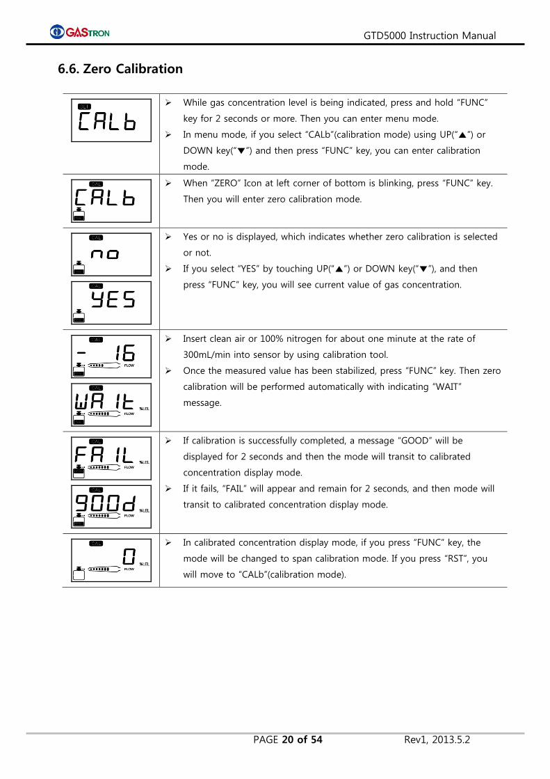
While gas concentration level is being indicated, press and hold “FUNC”
key for 2 seconds or more. Then you can enter menu mode.
In menu mode, if you select “CALb”(calibration mode) using UP(“▲”) or
DOWN key(“▼”) and then press “FUNC” key, you can enter calibration
mode.
When ”ZERO” Icon at left corner of bottom is blinking, press “FUNC” key.
Then you will enter zero calibration mode.
Yes or no is displayed, which indicates whether zero calibration is selected
or not.
If you select “YES” by touching UP(“▲”) or DOWN key(“▼”), and then
press “FUNC” key, you will see current value of gas concentration.
Insert clean air or 100% nitrogen for about one minute at the rate of
300mL/min into sensor by using calibration tool.
Once the measured value has been stabilized, press “FUNC” key. Then zero
calibration will be performed automatically with indicating “WAIT”
message.
If calibration is successfully completed, a message “GOOD” will be
displayed for 2 seconds and then the mode will transit to calibrated
concentration display mode.
If it fails, “FAIL” will appear and remain for 2 seconds, and then mode will
transit to calibrated concentration display mode.
In calibrated concentration display mode, if you press “FUNC” key, the
mode will be changed to span calibration mode. If you press “RST”, you
will move to “CALb”(calibration mode).

GTD5000 Instruction Manual
PAGE 21 of 54 Rev1, 2013.5.2
6.7. Span Calibration
While gas concentration level is being indicated, press and hold “FUNC”
key for 2 seconds or more. Then you will enter menu selection mode.
In menu mode, if you select “CALb” using UP(“▲”) or DOWN key(“▼”) and
then press “FUNC” key, you can enter calibration mode.
Select “SPAN” icon at left corner of bottom using UP(“▲”) or DOWN
key(“▼”). And then if you press “FUNC” key, you will enter span calibration
mode.
Select Yes or No for selecting further progress of span calibration. Select
“YES” using UP(“▲”) or DOWN key(“▼”), and then press “FUNC” key, if you
want to step forward.
In this mode, you can set standard value of gas. While concentration value
is blinking, adjust value using UP(“▲”) or DOWN key(“▼”). And then press
“FUNC” key.
Insert standard gas for about 1 minute at the rate of 300mL/min into
sensor with calibration tool. Once the measurement has been stabilized,
press “FUNC” key. Then span calibration automatically will be performed
and “WAIT” message will be displayed.
If calibration is successfully completed, a message “GOOD” will be
displayed for two seconds and then the mode will be changed to
calibrated concentration display mode.
If it fails, “FAIL” will appear and remain for two seconds. Subsequently the
mode will be changed to calibrated concentration display mode.
In calibrated concentration display mode, if you press “FUNC” key, “END”
message will be shown. At this moment, if you press “FUNC” again, the
mode will be changed to “CALb” mode.
This message indicates that calibration setting and updating is completed.
If you press “FUNC” key, it will go back to menu mode.

GTD5000 Instruction Manual
PAGE 22 of 54 Rev1, 2013.5.2
6.8. Alarm Data Setting (Alarm mode)
While gas concentration level is being indicated, press and hold “FUNC”
key for 2 seconds or more. Then you can enter menu selection mode.
In menu mode, if you select “ALAm”(Alarm mode) using UP(“▲”) or DOWN
key(“▼”) and then press “FUNC” key, you can enter alarm setting mode.
It is a mode in which you can set alarm latch type. Whenever you press
UP(“▲”) or DOWN key(“▼”), the value will be changed alternatively
between “ON” and “OFF”.
Press “FUNC” key when desired alarm latch type is being displayed, then
alarm latch type is set to be desired value. It will progress to next item.
There are two types of alarm latch: “ON” and “OFF”. In case of OFF, alarm
will be reset automatically. In case of ON, alarm will be turned off only
when the user explicitly presses “RESET” key.
A message “AL-1” means that it is alarm1 setting function.
It is a mode in which you can set the value of alarm1 level. The value can
be set within 90% range of 1~high scale.
Whenever UP(“▲”) or DOWN key(“▼”) is pressed, alarm1 value will
increase or decreases.
Press “FUNC” key when desired value is being displayed. Then alarm1
value is set as desired. It will progress to next item.
When the device is initially released, alarm level is set to be concentration
value specified by domestic laws and regulations.
It is a mode in which you can set operating direction of alarm1. Whenever
UP(“▲”) or DOWN key(“▼”) is pressed, “1H” or “1L” will be displayed
alternatively.
“1H” indicates alarm will operate when measured value equals to or is
higher than alarm1 setting value. On the other hand, “1L” indicates alarm
will operate when it equals to or is less than alarm1 value.
Press “FUNC” key when desired mode is being displayed. Then the mode
is set as desired. Subsequently, it will progress to next item.
Factory setting for alarm type is as follows:
Flammable:1H & 2H / Oxygen: 2H & 1L / Toxic: 1H & 2H type.
It is a mode in which you can set dead band value with which alarm1
operates. Select value using UP(“▲”) or DOWN key(“▼”).
In case that alarm1 is in “1H” mode, alarm1 operates only when measured
value equals to or is higher than alarm value + dead band. And alarm1 is
turned off when it equals to or is less than alarm value – dead band.
GTD5000 Instruction Manual
PAGE 23 of 54 Rev1, 2013.5.2
In case that alarm1 is in “1L”, alarm1 operates only when measured value
equals to or is less than alarm value – dead band. And alarm1 is turned off
when it equals to or is higher than alarm value + dead band.
Press “FUNC” key when desired alarm1 dead band value is being
displayed. Then alarm1 dead band value is set as desired, and the setting
will progress to next item.
This function allows the user to set hysteresis value. Its purpose is to avoid
the symptom in which alarm1 is turned on and off repeatedly when gas
concentration value reaches around alarm1 setting value. When the
product is released from manufacturing factory, this value is set to 0.
For example, alarm is turned on 22% LEL and off 18% LEL in case of
20%LEL for alarm setting and 2%LEL for dead band.
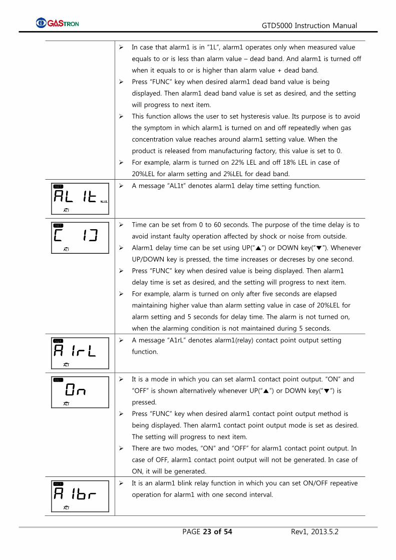
A message “AL1t” denotes alarm1 delay time setting function.
Time can be set from 0 to 60 seconds. The purpose of the time delay is to
avoid instant faulty operation affected by shock or noise from outside.
Alarm1 delay time can be set using UP(“▲”) or DOWN key(“▼”). Whenever
UP/DOWN key is pressed, the time increases or decreses by one second.
Press “FUNC” key when desired value is being displayed. Then alarm1
delay time is set as desired, and the setting will progress to next item.
For example, alarm is turned on only after five seconds are elapsed
maintaining higher value than alarm setting value in case of 20%LEL for
alarm setting and 5 seconds for delay time. The alarm is not turned on,
when the alarming condition is not maintained during 5 seconds.
A message “A1rL” denotes alarm1(relay) contact point output setting
function.
It is a mode in which you can set alarm1 contact point output. “ON” and
“OFF” is shown alternatively whenever UP(“▲”) or DOWN key(“▼”) is
pressed.
Press “FUNC” key when desired alarm1 contact point output method is
being displayed. Then alarm1 contact point output mode is set as desired.
The setting will progress to next item.
There are two modes, “ON” and “OFF” for alarm1 contact point output. In
case of OFF, alarm1 contact point output will not be generated. In case of
ON, it will be generated.
It is an alarm1 blink relay function in which you can set ON/OFF repeative
operation for alarm1 with one second interval.

GTD5000 Instruction Manual
PAGE 24 of 54 Rev1, 2013.5.2
By default, it is set to OFF. If it is switched to ON, alarm1 relay output will
operate ON and OFF alternatively every one second.
A message “AL-2” denotes alarm2 value setting function.
It is a mode in which you can set alarm2 level value. The value can be set
within 90% of 1~high scale.
Whenever UP(“▲”) or DOWN key(“▼”key) is pressed, alarm2 value
increases or decreases.
Press “FUNC” key when desired value is being displayed. Then alarm2 is
set as desired. Subsequently, the setting will progress to next item.
Alarm level is set as specified by domestic laws and regulations, when the
product is initially released.
It is a mode in which you can set operating direction of alarm2. Whenever
UP(“▲”) or DOWN key(“▼”) is pressed, “2H” or “2L” will be displayed
alternatively.
“2H” indicates that alarm will operate when measured value equals to or is
higher than alarm2 setting value. On the other hand, “2L” indicates alarm
will operate when it equals to or is less than alarm2 value.
Press “FUNC” key when desired mode is being displayed. Then the mode
is set as desired. The setting will progress to next item.
When the product is initially released from factory, alarm type is se as
follows: Flammable: 1H & 2H / Oxygen: 2H & 1L / Toxic: 1H & 2H Type
It is a mode in which you can set dead band value with which alarm2
operates. Select value using UP(“▲”) or DOWN key(“▼”).
In case that alarm2 is “2H” mode, alarm2 operates when measured value
equals to or is higher than alarm2 value + dead band. And alarm2 is
turned off when it equals to or is less than alarm2 value – dead band.
In case that alarm2 is “2L” mode, alarm2 operates only when measured
value equals to or is less than alarm value – dead band. And alarm2 is
turned off when it equals to or is higher than alarm value + dead band.
Press “FUNC” key when desired alarm2 dead band value is being
displayed, then alarm1 dead band value is set as desired, and the setting
will progress to next item.
This function allows the user to set hysteresis value in order to avoid the
symptom in which alarm2 is turned on and off repeatedly when gas
concentration value reaches around alarm2 setting value. When the
product is released from manufacturing factory, this value is set to 0.
For example, alarm is turned on 22% LEL and off 18% LEL in case of
20%LEL for alarm setting and 2%LEL for dead band.
GTD5000 Instruction Manual
PAGE 25 of 54 Rev1, 2013.5.2
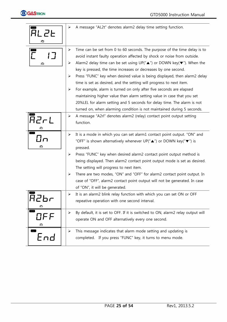
A message “AL2t” denotes alarm2 delay time setting function.
Time can be set from 0 to 60 seconds. The purpose of the time delay is to
avoid instant faulty operation affected by shock or noise from outside.
Alarm2 delay time can be set using UP(“▲”) or DOWN key(▼”). When the
key is pressed, the time increases or decreases by one second.
Press “FUNC” key when desired value is being displayed, then alarm2 delay
time is set as desired, and the setting will progress to next item.
For example, alarm is turned on only after five seconds are elapsed
maintaining higher value than alarm setting value in case that you set
20%LEL for alarm setting and 5 seconds for delay time. The alarm is not
turned on, when alarming condition is not maintained during 5 seconds.
A message “A2rl” denotes alarm2 (relay) contact point output setting
function.
It is a mode in which you can set alarm1 contact point output. “ON” and
“OFF” is shown alternatively whenever UP(“▲”) or DOWN key(“▼”) is
pressed.
Press “FUNC” key when desired alarm2 contact point output method is
being displayed. Then alarm2 contact point output mode is set as desired.
The setting will progress to next item.
There are two modes, “ON” and “OFF” for alarm2 contact point output. In
case of “OFF”, alarm2 contact point output will not be generated. In case
of “ON”, it will be generated.
It is an alarm2 blink relay function with which you can set ON or OFF
repeative operation with one second interval.
By default, it is set to OFF. If it is switched to ON, alarm2 relay output will
operate ON and OFF alternatively every one second.
This message indicates that alarm mode setting and updating is
completed. If you press “FUNC” key, it turns to menu mode.

GTD5000 Instruction Manual
PAGE 26 of 54 Rev1, 2013.5.2
6.9. Current Time Reading and Setting
While gas concentration level is being indicated, press and hold “FUNC”
key for 2 seconds or more. Then you will enter menu selection mode.
In case that alarm1 is in “1H” mode, alarm1 operates only when
measured value equals to or is higher than alarm value + dead band. And
alarm1 is turned off when it equals to or is less than alarm value – dead
band.
If you select “CLOC” using UP(“▲”) or DOWN keu(“▼”) and press “FUNC”
key, mode will turn into current time reading and setting mode.
Current time is presented in following way: year/month,day/hour,minute. If
you press and hold UP(“▲”) and DOWN(“▼”) key at the same time for a
while, when hour and minute is being displayed, the mode will turn into
time setting mode. In this mode, year/month,day/hour,minute will blink on
and off. Time setting can be done in that sequence.
(Year setting) (Date setting) (Time setting)
It is a mode in which you can read sensor manufacturing date (sensor
time). Sensor manufacturing date can be registered in S-dt(Sensor data)
mode.
(Year setting) (Date setting) (Time setting)
It is a mode in which you can read lastest time when span calibration was
done. This time information is automatically set when you do span
calibration in “CALb” mode.
(Year setting) (Date setting) (Time setting)
This message indicates that time mode setting and updating is completed.
If you press “FUNC” key, it turns to menu mode.

GTD5000 Instruction Manual
PAGE 27 of 54 Rev1, 2013.5.2
6.10. Checking and Setting Sensor Data
While gas concentration level is being indicated, press and hold “FUNC”
key for 2 seconds or more. Then you will enter menu selection mode.
In menu mode, if you select “S-dt”(sensor data mode) using UP(“▲”) or
DOWN key(“▼”) and press “FUNC” key, the mode will turn into sensor
data checking and setting mode.
It is a “tYPE” (Sensor type) mode, in which sensor type of sensor cartridge
is indicated.
“ES” denotes flammable type sensor. “tS” denotes toxic type.
It is a “SdIr”(Sensor direction) mode, in which polarity of sensor output
voltage is indicated.
“PLUS” means that sensor generates output in a direction of (+) in
correspondence with gas concentration. “mIUS”(minus) means that sensor
generates output in a direction of (-). Plus or Minus can be selected using
UP(“▲”) or DOWN key(“▼”).
It is a “GAIn” (gain mode) in which you can set gain value for sensor
output voltage of sensor cartridge.
You can set gain to be one of three value as follows : “G-1”,”G-2” and ”G-
4”. By default, it is set to be G-1, which means one time of gain. G-2 and
G-4 denotes two times and four times gain respectively.
It denotes sensor output mode(“SOUt”). In this mode, you can read sensor
output voltage (mV) of sensor cartridge.
It means an output voltage of sensor.
It denotes sensor power mode (“SPWr”). In this mode, you can check bias
voltage of sensor. (unit: V)
It indicates an applied voltage to sensor (Bias voltage).
GTD5000 Instruction Manual
PAGE 28 of 54 Rev1, 2013.5.2
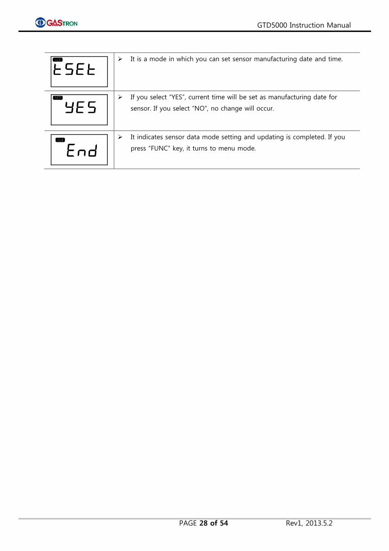
It is a mode in which you can set sensor manufacturing date and time.
If you select “YES”, current time will be set as manufacturing date for
sensor. If you select “NO”, no change will occur.
It indicates sensor data mode setting and updating is completed. If you
press “FUNC” key, it turns to menu mode.
GTD5000 Instruction Manual
PAGE 29 of 54 Rev1, 2013.5.2
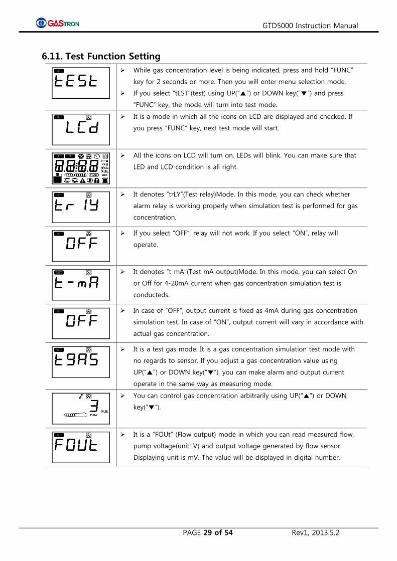
6.11. Test Function Setting
While gas concentration level is being indicated, press and hold “FUNC”
key for 2 seconds or more. Then you will enter menu selection mode.
If you select “tEST”(test) using UP(“▲”) or DOWN key(“▼”) and press
“FUNC” key, the mode will turn into test mode.
It is a mode in which all the icons on LCD are displayed and checked. If
you press “FUNC” key, next test mode will start.
All the icons on LCD will turn on. LEDs will blink. You can make sure that
LED and LCD condition is all right.
It denotes “trLY”(Test relay)Mode. In this mode, you can check whether
alarm relay is working properly when simulation test is performed for gas
concentration.
If you select “OFF”, relay will not work. If you select “ON”, relay will
operate.
It denotes “t-mA”(Test mA output)Mode. In this mode, you can select On
or Off for 4-20mA current when gas concentration simulation test is
conducteds.
In case of “OFF”, output current is fixed as 4mA during gas concentration
simulation test. In case of “ON”, output current will vary in accordance with
actual gas concentration.
It is a test gas mode. It is a gas concentration simulation test mode with
no regards to sensor. If you adjust a gas concentration value using
UP(“▲”) or DOWN key(“▼”), you can make alarm and output current
operate in the same way as measuring mode.
You can control gas concentration arbitrarily using UP(“▲”) or DOWN
key(“▼”).
It is a “FOUt” (Flow output) mode in which you can read measured flow,
pump voltage(unit: V) and output voltage generated by flow sensor.
Displaying unit is mV. The value will be displayed in digital number.

GTD5000 Instruction Manual
PAGE 30 of 54 Rev1, 2013.5.2
It indicates a measured flow. You can read pump voltage(unit:V) using
UP(“▲”) or DOWN key(“▼”). You can also change the pump voltage value
using UP(“▲”) or DOWN key(“▼”).
It indicates an output voltage(mV) generated by flow sensor. You can read
pump voltage(unit:V) using UP(“▲”) or DOWN key(“▼”). You can also
change the pump voltage value using UP(“▲”) or DOWN key(“▼”).
It is a mode in which a current consumed by pyrolyzer power is presented.
In a “ConF” mode, if you select “OFF” which means pyrolyzer is not used,
consumption power will be displayed as “OFF”.
It is a “tEmp”(Temperture) mode in which a temperature of gas detector
will be indicated.
It indicates an inside temperature of gas detector.
It is a “FrAM”(FRAM) test mode.
According to test result, a message will appear. If it is successful,
“Good”(900d) will come up. Otherwise, “FAIL” comes up.
It indicates test mode setting and updating is completed. If you press
“FUNC” key, it turns to menu mode.
GTD5000 Instruction Manual
PAGE 31 of 54 Rev1, 2013.5.2
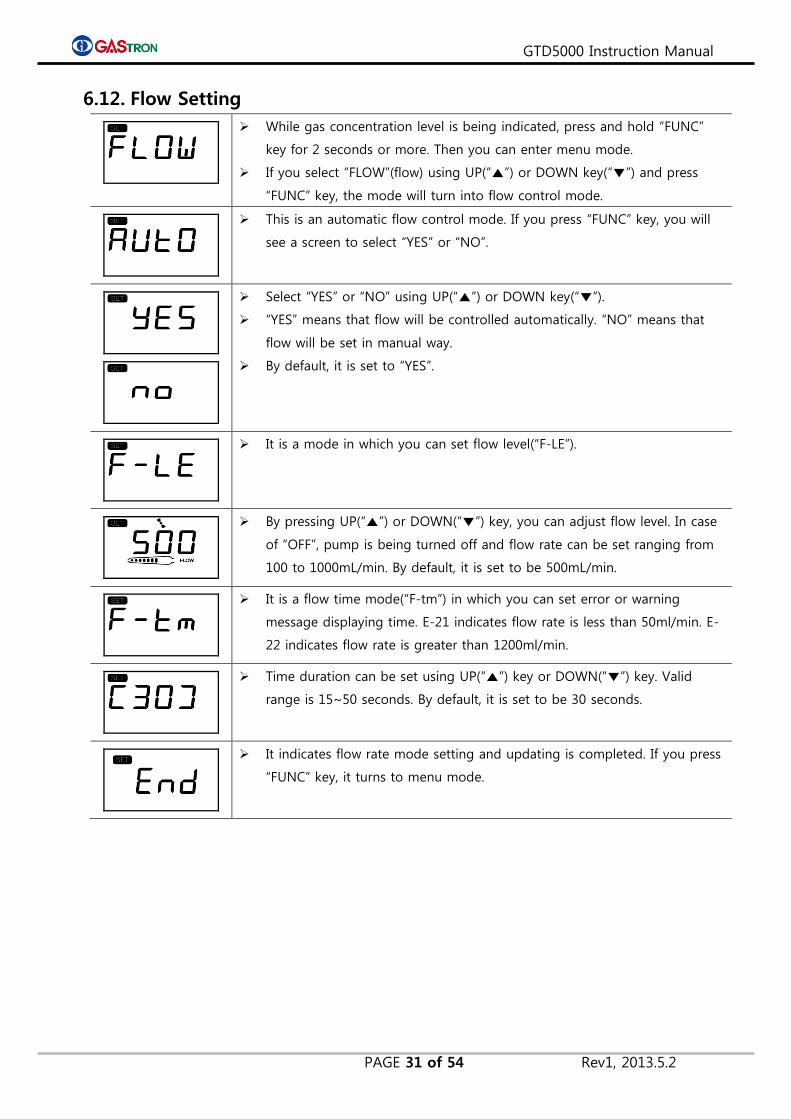
6.12. Flow Setting
While gas concentration level is being indicated, press and hold “FUNC”
key for 2 seconds or more. Then you can enter menu mode.
If you select “FLOW”(flow) using UP(“▲”) or DOWN key(“▼”) and press
“FUNC” key, the mode will turn into flow control mode.
This is an automatic flow control mode. If you press “FUNC” key, you will
see a screen to select “YES” or “NO”.
Select “YES” or “NO” using UP(“▲”) or DOWN key(“▼”).
“YES” means that flow will be controlled automatically. “NO” means that
flow will be set in manual way.
By default, it is set to “YES”.
It is a mode in which you can set flow level(“F-LE”).
By pressing UP(“▲”) or DOWN(“▼”) key, you can adjust flow level. In case
of “OFF”, pump is being turned off and flow rate can be set ranging from
100 to 1000mL/min. By default, it is set to be 500mL/min.
It is a flow time mode(“F-tm”) in which you can set error or warning
message displaying time. E-21 indicates flow rate is less than 50ml/min. E-
22 indicates flow rate is greater than 1200ml/min.
Time duration can be set using UP(“▲”) key or DOWN(“▼”) key. Valid
range is 15~50 seconds. By default, it is set to be 30 seconds.
It indicates flow rate mode setting and updating is completed. If you press
“FUNC” key, it turns to menu mode.
GTD5000 Instruction Manual
PAGE 32 of 54 Rev1, 2013.5.2
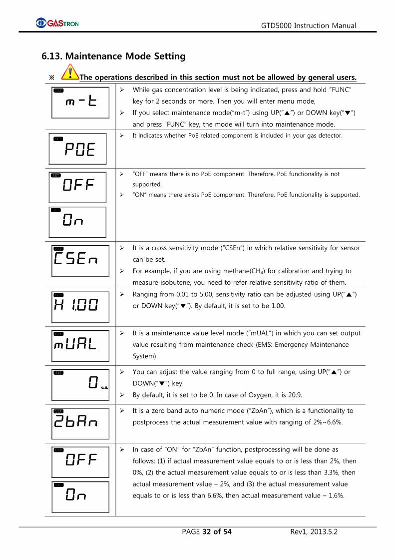
6.13. Maintenance Mode Setting
※ The operations described in this section must not be allowed by general users.
While gas concentration level is being indicated, press and hold “FUNC”
key for 2 seconds or more. Then you will enter menu mode,
If you select maintenance mode(“m-t”) using UP(“▲”) or DOWN key(“▼”)
and press “FUNC” key, the mode will turn into maintenance mode.
It indicates whether PoE related component is included in your gas detector.
“OFF” means there is no PoE component. Therefore, PoE functionality is not
supported.
“ON” means there exists PoE component. Therefore, PoE functionality is supported.
It is a cross sensitivity mode (“CSEn”) in which relative sensitivity for sensor
can be set.
For example, if you are using methane(CH4) for calibration and trying to
measure isobutene, you need to refer relative sensitivity ratio of them.
Ranging from 0.01 to 5.00, sensitivity ratio can be adjusted using UP(“▲”)
or DOWN key(“▼”). By default, it is set to be 1.00.
It is a maintenance value level mode (“mUAL”) in which you can set output
value resulting from maintenance check (EMS: Emergency Maintenance
System).
You can adjust the value ranging from 0 to full range, using UP(“▲”) or
DOWN(“▼”) key.
By default, it is set to be 0. In case of Oxygen, it is 20.9.
It is a zero band auto numeric mode (“ZbAn”), which is a functionality to
postprocess the actual measurement value with ranging of 2%~6.6%.
In case of “ON” for “ZbAn” function, postprocessing will be done as
follows: (1) if actual measurement value equals to or is less than 2%, then
0%, (2) the actual measurement value equals to or is less than 3.3%, then
actual measurement value – 2%, and (3) the actual measurement value
equals to or is less than 6.6%, then actual measurement value – 1.6%.
GTD5000 Instruction Manual
PAGE 33 of 54 Rev1, 2013.5.2
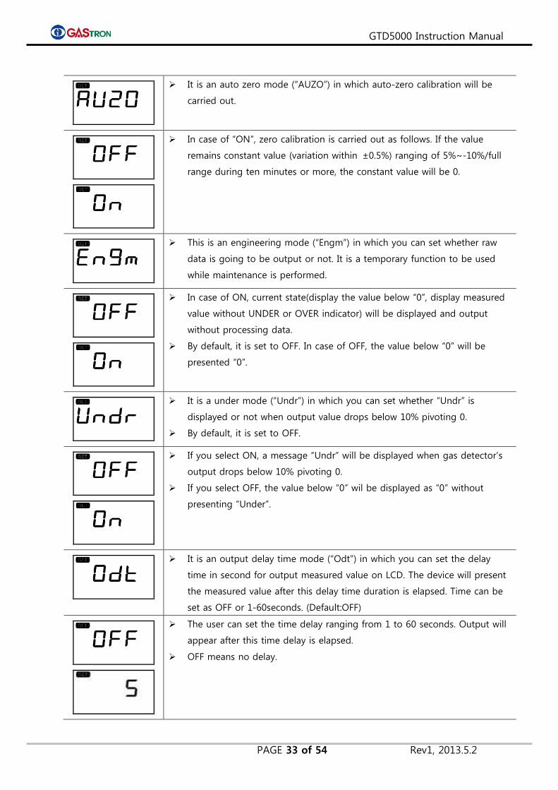
It is an auto zero mode (“AUZO”) in which auto-zero calibration will be
carried out.
In case of “ON”, zero calibration is carried out as follows. If the value
remains constant value (variation within ±0.5%) ranging of 5%~-10%/full
range during ten minutes or more, the constant value will be 0.
This is an engineering mode (“Engm”) in which you can set whether raw
data is going to be output or not. It is a temporary function to be used
while maintenance is performed.
In case of ON, current state(display the value below “0”, display measured
value without UNDER or OVER indicator) will be displayed and output
without processing data.
By default, it is set to OFF. In case of OFF, the value below “0” will be
presented “0”.
It is a under mode (“Undr”) in which you can set whether “Undr” is
displayed or not when output value drops below 10% pivoting 0.
By default, it is set to OFF.
If you select ON, a message “Undr” will be displayed when gas detector’s
output drops below 10% pivoting 0.
If you select OFF, the value below “0” wil be displayed as “0” without
presenting “Under”.
It is an output delay time mode (“Odt”) in which you can set the delay
time in second for output measured value on LCD. The device will present
the measured value after this delay time duration is elapsed. Time can be
set as OFF or 1-60seconds. (Default:OFF)
The user can set the time delay ranging from 1 to 60 seconds. Output will
appear after this time delay is elapsed.
OFF means no delay.
GTD5000 Instruction Manual
PAGE 34 of 54 Rev1, 2013.5.2
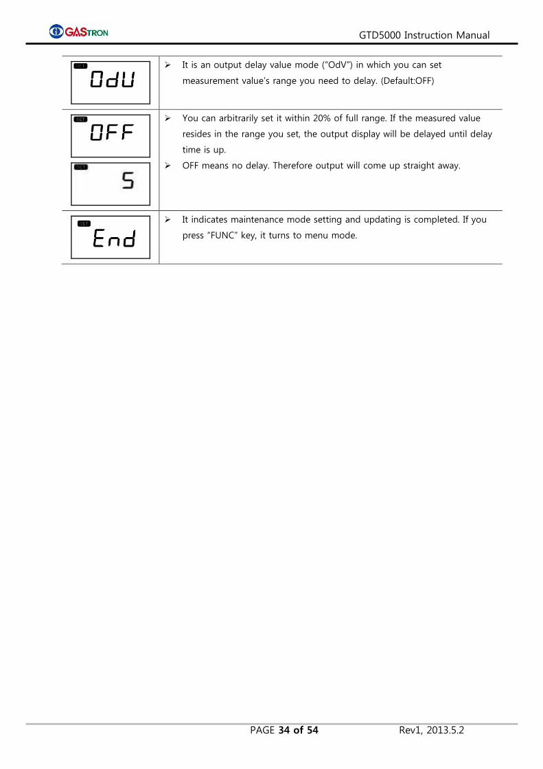
It is an output delay value mode (“OdV”) in which you can set
measurement value’s range you need to delay. (Default:OFF)
You can arbitrarily set it within 20% of full range. If the measured value
resides in the range you set, the output display will be delayed until delay
time is up.
OFF means no delay. Therefore output will come up straight away.
It indicates maintenance mode setting and updating is completed. If you
press “FUNC” key, it turns to menu mode.
GTD5000 Instruction Manual
PAGE 35 of 54 Rev1, 2013.5.2
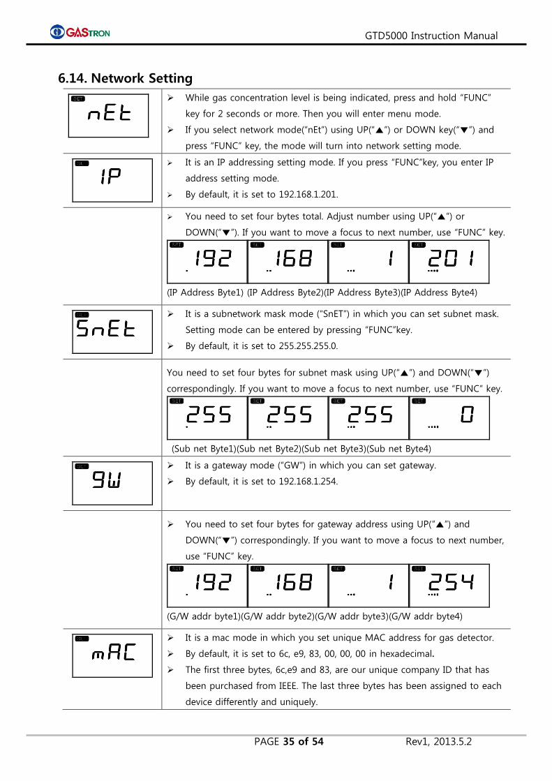
6.14. Network Setting
While gas concentration level is being indicated, press and hold “FUNC”
key for 2 seconds or more. Then you will enter menu mode.
If you select network mode(“nEt”) using UP(“▲”) or DOWN key(“▼”) and
press “FUNC” key, the mode will turn into network setting mode.
It is an IP addressing setting mode. If you press “FUNC”key, you enter IP
address setting mode.
By default, it is set to 192.168.1.201.
You need to set four bytes total. Adjust number using UP(“▲”) or
DOWN(“▼”). If you want to move a focus to next number, use “FUNC” key.
(IP Address Byte1) (IP Address Byte2)(IP Address Byte3)(IP Address Byte4)
It is a subnetwork mask mode (“SnET”) in which you can set subnet mask.
Setting mode can be entered by pressing “FUNC”key.
By default, it is set to 255.255.255.0.
You need to set four bytes for subnet mask using UP(“▲”) and DOWN(“▼”)
correspondingly. If you want to move a focus to next number, use “FUNC” key.
(Sub net Byte1)(Sub net Byte2)(Sub net Byte3)(Sub net Byte4)
It is a gateway mode (“GW”) in which you can set gateway.
By default, it is set to 192.168.1.254.
You need to set four bytes for gateway address using UP(“▲”) and
DOWN(“▼”) correspondingly. If you want to move a focus to next number,
use “FUNC” key.
(G/W addr byte1)(G/W addr byte2)(G/W addr byte3)(G/W addr byte4)
It is a mac mode in which you set unique MAC address for gas detector.
By default, it is set to 6c, e9, 83, 00, 00, 00 in hexadecimal.
The first three bytes, 6c,e9 and 83, are our unique company ID that has
been purchased from IEEE. The last three bytes has been assigned to each
device differently and uniquely.
GTD5000 Instruction Manual
PAGE 36 of 54 Rev1, 2013.5.2
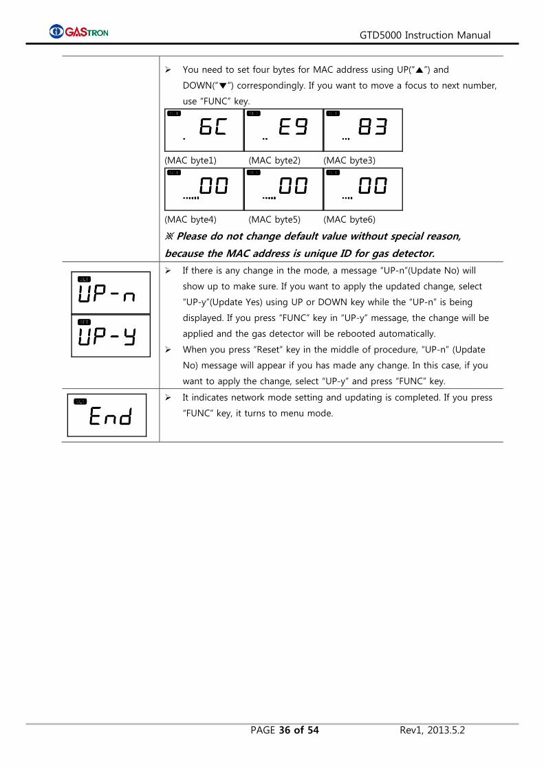
You need to set four bytes for MAC address using UP(“▲”) and
DOWN(“▼”) correspondingly. If you want to move a focus to next number,
use “FUNC” key.
(MAC byte1) (MAC byte2) (MAC byte3)
(MAC byte4) (MAC byte5) (MAC byte6)
※ Please do not change default value without special reason,
because the MAC address is unique ID for gas detector.
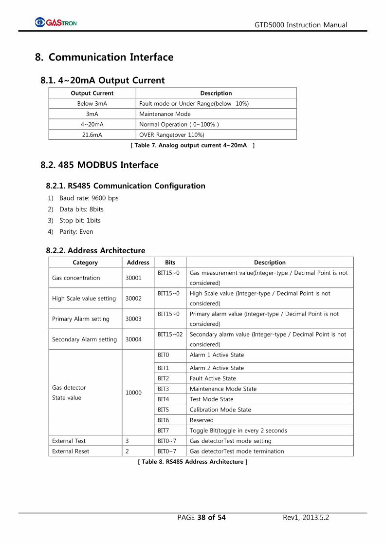
If there is any change in the mode, a message “UP-n”(Update No) will
show up to make sure. If you want to apply the updated change, select
“UP-y”(Update Yes) using UP or DOWN key while the “UP-n” is being
displayed. If you press “FUNC” key in “UP-y” message, the change will be
applied and the gas detector will be rebooted automatically.
When you press “Reset” key in the middle of procedure, “UP-n” (Update
No) message will appear if you has made any change. In this case, if you
want to apply the change, select “UP-y” and press “FUNC” key.
It indicates network mode setting and updating is completed. If you press
“FUNC” key, it turns to menu mode.

GTD5000 Instruction Manual
PAGE 37 of 54 Rev1, 2013.5.2
7. Error & Warning Message (Troubleshooting)
7.1. Error Code
Message Description & Condition Level
E-10 Sensor cartridge is not loaded to main body or is not qualified. Out of order
E-11 Communcation between sensor cartridge and main body is
broken Out of order
E-12 No sensor is included in sensor cartridge. Out of order
E-13 24C02(EPROM) in sensor PCB is malfunctioned. Out of order
E-19 Zero of sensor is too low (Under) Out of order
E-20 Flow sensor is not working properly (When sensor hose is
replaced) Out of order
E-21 Flow of the flow sensor is too low Out of order
E-22 Flow of the flow sensor is too high Out of order
E-30 The current of pyrolyzer is measured as below 50mA Out of order
E-31 Internal EEPROM is not recognized Out of order
E-32 The current of pyrolyzer is measured as over 550mA Out of order
[ Table 5. Error Code ]
7.2. Warning Code
Message Description & Condition Level
W-00 Time is not set. Warning
W-01 Calibration valid period has been expired. Warning
W-02 Manufacturing date of sensor is not set. Warning
[ Table 6. Warning Code]
GTD5000 Instruction Manual
PAGE 38 of 54 Rev1, 2013.5.2
8. Communication Interface
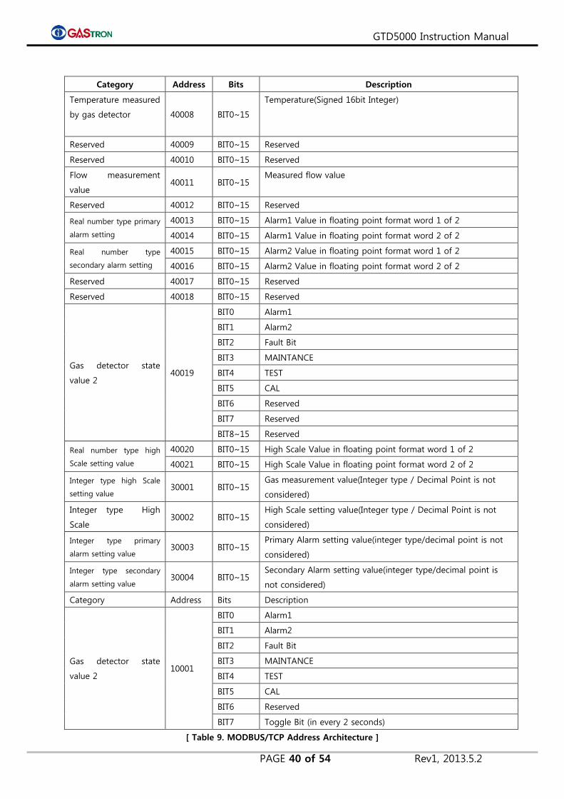
8.1. 4~20mA Output Current
Output Current Description
Below 3mA Fault mode or Under Range(below -10%)
3mA Maintenance Mode
4~20mA Normal Operation ( 0~100% )
21.6mA OVER Range(over 110%)
[ Table 7. Analog output current 4~20mA ]
8.2. 485 MODBUS Interface
8.2.1. RS485 Communication Configuration
1) Baud rate: 9600 bps
2) Data bits: 8bits
3) Stop bit: 1bits
4) Parity: Even
8.2.2. Address Architecture
Category Address Bits Description
Gas concentration 30001 BIT15~0 Gas measurement value(Integer-type / Decimal Point is not
considered)
High Scale value setting 30002 BIT15~0 High Scale value (Integer-type / Decimal Point is not
considered)
Primary Alarm setting 30003 BIT15~0 Primary alarm value (Integer-type / Decimal Point is not
considered)
Secondary Alarm setting 30004 BIT15~02 Secondary alarm value (Integer-type / Decimal Point is not
considered)
Gas detector
State value 10000
BIT0 Alarm 1 Active State
BIT1 Alarm 2 Active State
BIT2 Fault Active State
BIT3 Maintenance Mode State
BIT4 Test Mode State
BIT5 Calibration Mode State
BIT6 Reserved
BIT7 Toggle Bit(toggle in every 2 seconds
External Test 3 BIT0~7 Gas detectorTest mode setting
External Reset 2 BIT0~7 Gas detectorTest mode termination
[ Table 8. RS485 Address Architecture ]

GTD5000 Instruction Manual
PAGE 39 of 54 Rev1, 2013.5.2
8.3. MODBUS/TCP Interface
Category Address Bits Description
Gas detector
State value 1 40001
BIT0~3
Monitoring state
0: Warm up
1: Measurement Mode
2: Measurement Mode where alarm ouput is not allowed.
3: Reserved
4: Reserved
5: Reserved
6: Reserved
7: 4~20mA Calibration mode
8: Flow Calibration mode
9~15: Reserved
BIT4 Fault Active state
BIT5 Reserve
BIT6 Alarm 1 Active state
BIT7 Alarm 2 Active state
BIT8 Alarm1 Relay energized
BIT9 Alarm2 Relay energized
BIT10 Fault Relay energized
BIT11 Toggle Bit in every 2 seconds
BIT12~15 Reserved
Reserve 40002 BIT0~15 Reserved
Real number type gas
measurement value
40003 BIT0~15 Gas Concentration in floating point format word 1 of 2
40004 BIT0~15 Gas Concentration in floating point format word 2 of 2
Integer type gas
measurement value 40005 BIT0~15 Gas Concentration in integer Format
ErrorCode 40006 BIT0~15 Error Code
Decimal point
and units 40007
BIT0~2
Decimal point indicator(0~3)
0: 0 Point
1: 1 Point
2: 2 Point
3: 3 Point
4~7: Reserved
BIT3~7 Reserved
BIT8~11 Concentration units
0: Reserved
1: PPM
2: PPB
3: Reserved
4: % Volume
5~7: Reserved
8: % LEL
BIT12~15 Reserved
GTD5000 Instruction Manual
PAGE 40 of 54 Rev1, 2013.5.2
Category Address Bits Description
Temperature measured
by gas detector
40008 BIT0~15
Temperature(Signed 16bit Integer)
Reserved 40009 BIT0~15 Reserved
Reserved 40010 BIT0~15 Reserved
Flow measurement
value 40011 BIT0~15
Measured flow value
Reserved 40012 BIT0~15 Reserved
Real number type primary
alarm setting
40013 BIT0~15 Alarm1 Value in floating point format word 1 of 2
40014 BIT0~15 Alarm1 Value in floating point format word 2 of 2
Real number type
secondary alarm setting
40015 BIT0~15 Alarm2 Value in floating point format word 1 of 2
40016 BIT0~15 Alarm2 Value in floating point format word 2 of 2
Reserved 40017 BIT0~15 Reserved
Reserved 40018 BIT0~15 Reserved
Gas detector state
value 2 40019
BIT0 Alarm1
BIT1 Alarm2
BIT2 Fault Bit
BIT3 MAINTANCE
BIT4 TEST
BIT5 CAL
BIT6 Reserved
BIT7 Reserved
BIT8~15 Reserved
Real number type high
Scale setting value
40020 BIT0~15 High Scale Value in floating point format word 1 of 2
40021 BIT0~15 High Scale Value in floating point format word 2 of 2
Integer type high Scale
setting value 30001 BIT0~15
Gas measurement value(Integer type / Decimal Point is not
considered)
Integer type High
Scale 30002 BIT0~15
High Scale setting value(Integer type / Decimal Point is not
considered)
Integer type primary
alarm setting value 30003 BIT0~15
Primary Alarm setting value(integer type/decimal point is not
considered)
Integer type secondary
alarm setting value 30004 BIT0~15
Secondary Alarm setting value(integer type/decimal point is
not considered)
Category Address Bits Description
Gas detector state
value 2 10001
BIT0 Alarm1
BIT1 Alarm2
BIT2 Fault Bit
BIT3 MAINTANCE
BIT4 TEST
BIT5 CAL
BIT6 Reserved
BIT7 Toggle Bit (in every 2 seconds)
[ Table 9. MODBUS/TCP Address Architecture ]
GTD5000 Instruction Manual
PAGE 41 of 54 Rev1, 2013.5.2
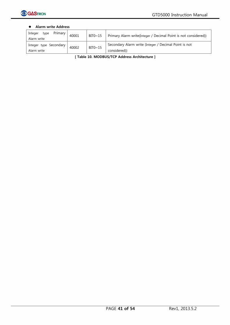
Alarm write Address
Integer type Primary
Alarm write 40001 BIT0~15 Primary Alarm write(Integer / Decimal Point is not considered))
Integer type Secondary
Alarm write 40002 BIT0~15
Secondary Alarm write (Integer / Decimal Point is not
considered))
[ Table 10. MODBUS/TCP Address Architecture ]
GTD5000 Instruction Manual
PAGE 42 of 54 Rev1, 2013.5.2
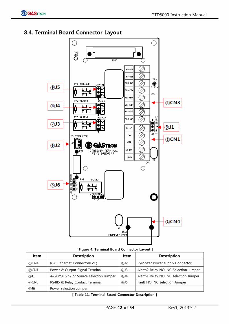
8.4. Terminal Board Connector Layout
[ Figure 4. Terminal Board Connector Layout ]
Item Description Item Description
①CN4 RJ45 Ethernet Connector(PoE) ⑥J2 Pyrolyzer Power supply Connector
②CN1 Power & Output Signal Terminal ⑦J3 Alarm2 Relay NO, NC Selection Jumper
③J1 4~20mA Sink or Source selection Jumper ⑧J4 Alarm1 Relay NO, NC selection Jumper
④CN3 RS485 & Relay Contact Terminal ⑨J5 Fault NO, NC selection Jumper
⑤J6 Power selection Jumper
[ Table 11. Terminal Board Connector Description ]

GTD5000 Instruction Manual
PAGE 43 of 54 Rev1, 2013.5.2
8.5. Terminal Board Connector Detailed Description
8.5.1. Power & Output Signal Terminal(CN1)
Item Description
E.+V External power input connector in case of J1 SINK selected
mA 4~20mA output connector
GND mA and Gas detector power GND
+24V Gas detector Power DC +24V
GND Gas detector Power GND
[Table 12. Detailed Description on CN1]
8.5.2. RS485 & Relay Contact Terminal(CN3)
Item Description
RS485A RS485 Communication connector A
RS485B RS485 Communication connector B
TRB-OUT Trouble relay output connector
TRB-COM Trouble relayCommon connector
AL1-OUT Alarm1 relay output connector
AL1-COM Alarm1 relayCommon connector
AL2-OUT Alarm2 relay output connector
AL2-COM Alarm2 relayCommon connector
[ Table 13. Detailed Description on CN3 ]
GTD5000 Instruction Manual
PAGE 44 of 54 Rev1, 2013.5.2
9. Connector Wiring Diagram Untie screw fixing case cover in front of detector, and remove the case cover. Now untie two screws; one is
fixing main sampling, and the other is fixing pump assembly. And then pull it toward yourself and remove the
cover. You can find terminal PCB inside.
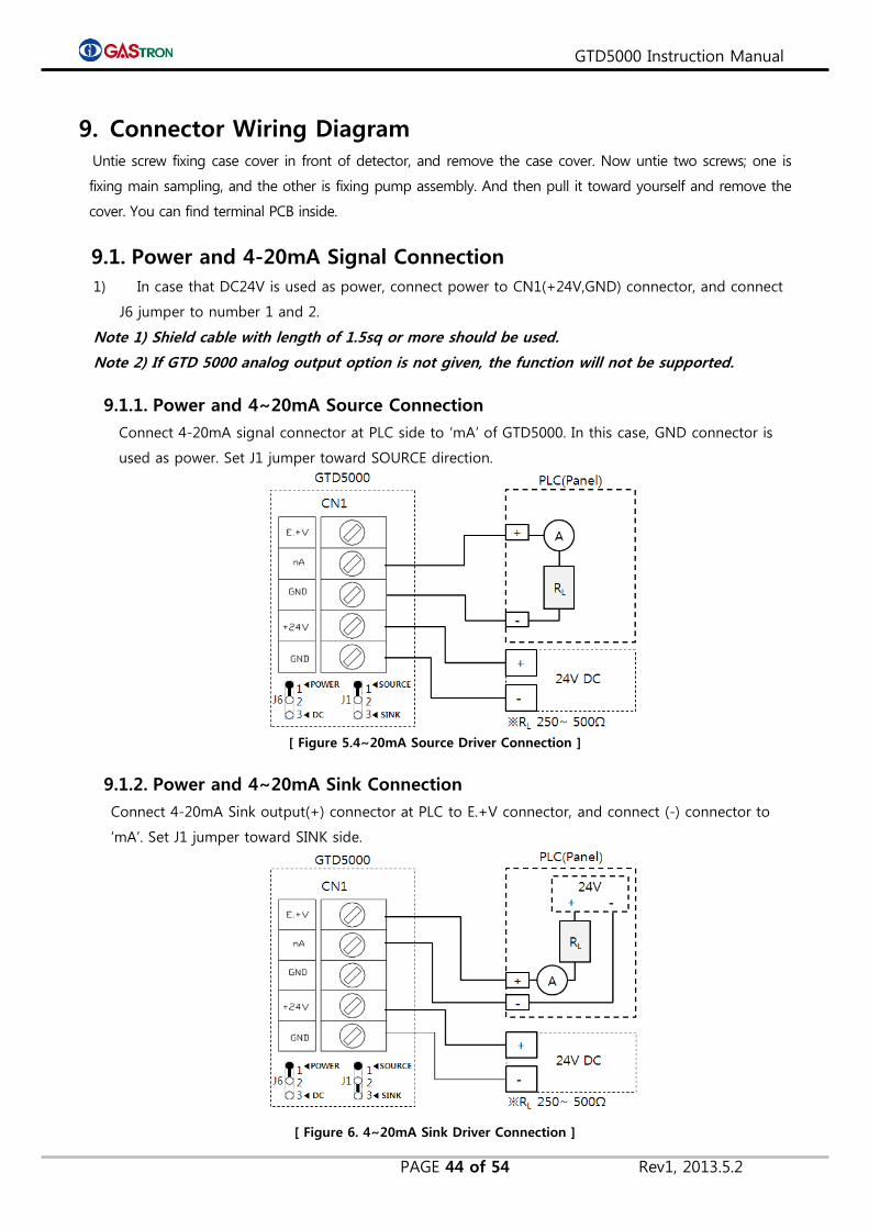
9.1. Power and 4-20mA Signal Connection
1) In case that DC24V is used as power, connect power to CN1(+24V,GND) connector, and connect
J6 jumper to number 1 and 2.
Note 1) Shield cable with length of 1.5sq or more should be used.
Note 2) If GTD 5000 analog output option is not given, the function will not be supported.
9.1.1. Power and 4~20mA Source Connection
Connect 4-20mA signal connector at PLC side to ‘mA’ of GTD5000. In this case, GND connector is
used as power. Set J1 jumper toward SOURCE direction.
[ Figure 5.4~20mA Source Driver Connection ]
9.1.2. Power and 4~20mA Sink Connection
Connect 4-20mA Sink output(+) connector at PLC to E.+V connector, and connect (-) connector to
‘mA’. Set J1 jumper toward SINK side.
[ Figure 6. 4~20mA Sink Driver Connection ]
GTD5000 Instruction Manual
PAGE 45 of 54 Rev1, 2013.5.2
9.2. Alarm signal connection
Trouble, alarm, relay connected to CN3 should be conncted described as follows.
Note 1) Relay is a type of SPDT, and a dry contact with 250V / 1A capacity.
1) Trouble Relay Output Connection
Connector Name Fault Relay Contact Jumper Setting
TRB-OUT Trouble Relay normally Closed J5 Jumper NC on
Trouble Relay normally Open J5 Jumper NO on
TRB-COM Trouble Relay Common -
2) Alarm1 Relay Output Connection
Connector Name Fault Relay Contact Jumper Setting
AL1-OUT Alarm1 Relay normally Closed J4 Jumper NC on
Alarm1 Relay normally Open J4 Jumper NO on
AL1-COM Trouble Relay Common -
3) Alarm2Relay Output Connection
Connector Name Fault Relay Contact Jumper Setting
AL2-OUT Alarm2 Relay normally Closed J3 Jumper NC on
Alarm2 Relay normally Open J3 Jumper NO on
AL2-COM Trouble Relay Common -
9.3. RS-485 Communication Signal Connection
Connect RS-485A and RS-485B of CN2 to master connectors as follows.
Connector Name Master Connector Name Note
RS485A ‘TRXD+’ or ‘A’ or ‘P’
RS485B ‘TRXD-’ or ‘B’ or ‘N’
Note 1) RS-485 dedicated cable should be used.
Note 2) If RS485 option is not given in your GTD5000 device, the function will not be supported.

GTD5000 Instruction Manual
PAGE 46 of 54 Rev1, 2013.5.2
9.4. Ethernet Signal Connection
In case of using PoE Ethernet, the device conforming to IEEE802.3af standard must be used. Shielded
CAT5 cable must be applied when connecting.
Note 1) If PoE option is not given in your GTD5000, this function will not be supported.
9.4.1. Connection in case of using PoE
When using PoE power, set J6 jumper toward DC side.
[ Figure 7. PoE Configuration ]
9.4.2. PoE Connection in case of using Pyrolyzer option
In case of using Pyrolyzer, separate DC power should be supplied to the GTD5000. Set J6 jumper
toward DC side.
[ Figure 8. PoE Configuration in case of using Pyrolyzer ]
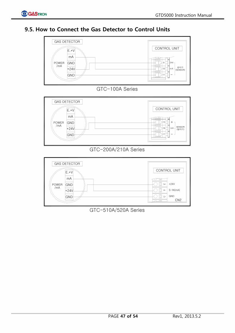
GTD5000 Instruction Manual
PAGE 47 of 54 Rev1, 2013.5.2
9.5. How to Connect the Gas Detector to Control Units
-
mASENSOR(탐지기)
17
16
15 +
11
10
9
mA
24V
감지기(SENSOR)
-
CONTROL UNIT
GAS DETECTOR
GAS DETECTOR
GND
GAS DETECTOR
S-IN(mA)
GND
+24V
CN2
GTC-100A Series
GTC-200A/210A Series
GTC-510A/520A Series
POWER/mA
E.+V
mA
GND
+24V
GNDPOWER/mA
E.+V
mA
GND
+24V
GNDPOWER/mA
E.+V
mA
GND
+24V
CONTROL UNIT
CONTROL UNIT

GTD5000 Instruction Manual
PAGE 48 of 54 Rev1, 2013.5.2
10. Appearance and Dimensions
10.1. GTD-5000 Appearance and Dimensions
[ Figure 9. GTD-5000 Appearance and Dimensions ]

GTD5000 Instruction Manual
PAGE 49 of 54 Rev1, 2013.5.2
10.2. GTD-5000 & PY-1000 Appearance and Dimensions
13.5
90.2
[ Figure 10. GTD-5000 & PY-1000 Appearance and Dimensions ]

GTD5000 Instruction Manual
PAGE 50 of 54 Rev1, 2013.5.2
10.3. GTD-5000 & PY-2000 Appearance and Dimensions
[ Figure 11. GTD-5000 & PY-2000 Appearance and Dimensions ]

GTD5000 Instruction Manual
PAGE 51 of 54 Rev1, 2013.5.2
11. Precautions prior to Installation
11.1. Selection of installation site
(according to Industrial Safety and Health Regulations)
Please install gas leakage detecting alarm in accordance with the following recommendations to secure
maximum functionality.
1) Chemical facilities and facilities annexed thereto, such as compressor, valve, reactor and pipe joints
dealing with flammable and/or toxic material installed in and out of buildings with high probability of
gas leaks.
2) Location where gas is prone to stay due to vicinity of manufacturing facilities with fire source such
as heating device.
3) Joint area and vicinity thereof for filling with flammable and toxic meterials.
4) Substation, electricity distribution station, control room and the like placed within an explosion-
proof area
5) Other areas where gases are prone to stay.
11.2. Selection of installation site
(according to High Pressure Gas Safety Control Act)
Gas detector of gas leakage alarm should be installed as close as possible to a suspected area of gas leak.
Exceptionally, the gas detector should be installed at one of following areas in case of the area in which
ambient gas is prone to stay although no direct gas leakage is expected.
1) The gas leak detector installed outside of building must be positioned at an area where gas is
prone to stay taking into account of direction of wind change, wind speed, gas specific gravity and
the like.
2) The gas leak detector installed inside of building must be positioned at a lower part of the
building if specific gravity of gas to be detected is heavier than that of air, and at a higher part of
the building or close to ventilation if specific gravity of gas to be detected is lighter than that of air.
3) The alarm of gas leak detector must be installed at an area where the detector is mounted and where
staffs are available at all the times.

GTD5000 Instruction Manual
PAGE 52 of 54 Rev1, 2013.5.2
11.3. Things to keep in mind when installing
The gas detector should be installed at water-free area, since the sensing parts of the gas detector is
not hermetically sealed. If water such as raindrop permeates through the sensor, electrical fault or the
like might happen. If the device is exposed to rain, it is highly recommended to provide additional
protection using rain cover.
1) When installing, avoid the area where vibration and shock frequently happen. Vibration or shock
might affect an output.
2) When installing, avoid the area where temperature and humidity are too high, which might cause
malfunctioning.
3) When installing, avoid the area where electronic noise is generated. Also avoid the area where high
frequency and high voltage happen, for example, the area near motor, pump or high voltage cable.
4) Install the gas detector the area where it is easy to repair and maintain, because periodic
maintenance and calibration are required to ensure proper operation. Therefore, avoid the area
where it is tricky to repair and maintain.
11.4. Cable Wiring
For preventing undesired influence by external noise, we recommend to use shield type cable. In
addition, for preventing the device from damage upon impact, we recommend to user cable duct,
conduct pipe and flexable and so on. It is recommended that making connection between cables
be avoided. However, if inevitable, we recommend junction box be used when cables are
connected.
In case of inner pressure-resistant packing method applied, please use the cable of which outer
diameter is suitable for inner packing size and tightly fasten the cable gland in order not to cause
any inflow of gas or flame.
When explosion proof metal piping, install sealing fitting and fill it with compound after
completing piping work, in order to prevent any flow of flame caused by explosion or gas inside
of metal pipe. All other connecting and combining parts should be water-proof.
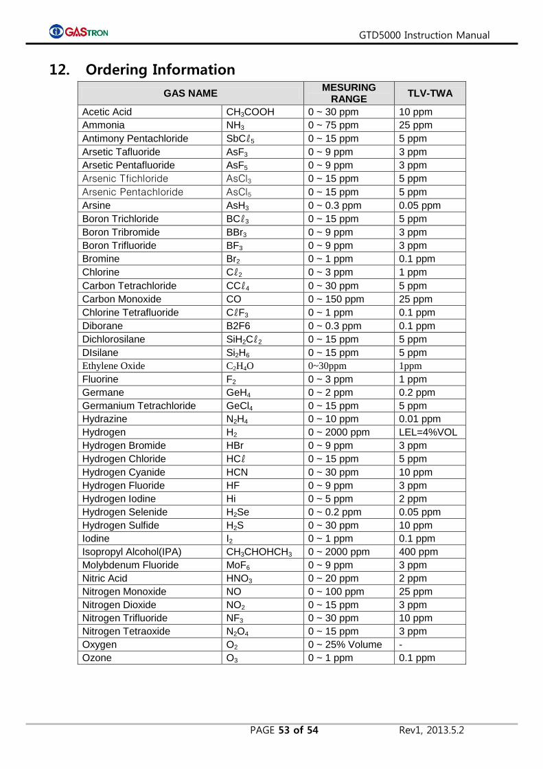
GTD5000 Instruction Manual
PAGE 53 of 54 Rev1, 2013.5.2
12. Ordering Information
GAS NAME MESURING
RANGE TLV-TWA
Acetic Acid CH3COOH 0 ~ 30 ppm 10 ppm
Ammonia NH3 0 ~ 75 ppm 25 ppm
Antimony Pentachloride SbCℓ5 0 ~ 15 ppm 5 ppm
Arsetic Tafluoride AsF3 0 ~ 9 ppm 3 ppm
Arsetic Pentafluoride AsF5 0 ~ 9 ppm 3 ppm
Arsenic Tfichloride AsCl3 0 ~ 15 ppm 5 ppm
Arsenic Pentachloride AsCl5 0 ~ 15 ppm 5 ppm
Arsine AsH3 0 ~ 0.3 ppm 0.05 ppm
Boron Trichloride BCℓ3 0 ~ 15 ppm 5 ppm
Boron Tribromide BBr3 0 ~ 9 ppm 3 ppm
Boron Trifluoride BF3 0 ~ 9 ppm 3 ppm
Bromine Br2 0 ~ 1 ppm 0.1 ppm
Chlorine Cℓ2 0 ~ 3 ppm 1 ppm
Carbon Tetrachloride CCℓ4 0 ~ 30 ppm 5 ppm
Carbon Monoxide CO 0 ~ 150 ppm 25 ppm
Chlorine Tetrafluoride CℓF3 0 ~ 1 ppm 0.1 ppm
Diborane B2F6 0 ~ 0.3 ppm 0.1 ppm
Dichlorosilane SiH2Cℓ2 0 ~ 15 ppm 5 ppm
DIsilane Si2H6 0 ~ 15 ppm 5 ppm
Ethylene Oxide C2H4O 0~30ppm 1ppm
Fluorine F2 0 ~ 3 ppm 1 ppm
Germane GeH4 0 ~ 2 ppm 0.2 ppm
Germanium Tetrachloride GeCl4 0 ~ 15 ppm 5 ppm
Hydrazine N2H4 0 ~ 10 ppm 0.01 ppm
Hydrogen H2 0 ~ 2000 ppm LEL=4%VOL
Hydrogen Bromide HBr 0 ~ 9 ppm 3 ppm
Hydrogen Chloride HCℓ 0 ~ 15 ppm 5 ppm
Hydrogen Cyanide HCN 0 ~ 30 ppm 10 ppm
Hydrogen Fluoride HF 0 ~ 9 ppm 3 ppm
Hydrogen Iodine Hi 0 ~ 5 ppm 2 ppm
Hydrogen Selenide H2Se 0 ~ 0.2 ppm 0.05 ppm
Hydrogen Sulfide H2S 0 ~ 30 ppm 10 ppm
Iodine I2 0 ~ 1 ppm 0.1 ppm
Isopropyl Alcohol(IPA) CH3CHOHCH3 0 ~ 2000 ppm 400 ppm
Molybdenum Fluoride MoF6 0 ~ 9 ppm 3 ppm
Nitric Acid HNO3 0 ~ 20 ppm 2 ppm
Nitrogen Monoxide NO 0 ~ 100 ppm 25 ppm
Nitrogen Dioxide NO2 0 ~ 15 ppm 3 ppm
Nitrogen Trifluoride NF3 0 ~ 30 ppm 10 ppm
Nitrogen Tetraoxide N2O4 0 ~ 15 ppm 3 ppm
Oxygen O2 0 ~ 25% Volume -
Ozone O3 0 ~ 1 ppm 0.1 ppm
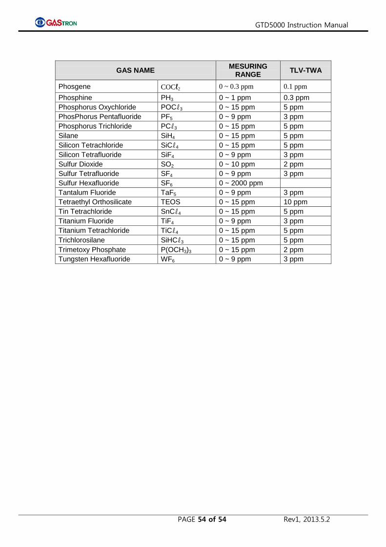
GTD5000 Instruction Manual
PAGE 54 of 54 Rev1, 2013.5.2
GAS NAME MESURING
RANGE TLV-TWA
Phosgene COCℓ2 0 ~ 0.3 ppm 0.1 ppm
Phosphine PH3 0 ~ 1 ppm 0.3 ppm
Phosphorus Oxychloride POCℓ3 0 ~ 15 ppm 5 ppm
PhosPhorus Pentafluoride PF5 0 ~ 9 ppm 3 ppm
Phosphorus Trichloride PCℓ3 0 ~ 15 ppm 5 ppm
Silane SiH4 0 ~ 15 ppm 5 ppm
Silicon Tetrachloride SiCℓ4 0 ~ 15 ppm 5 ppm
Silicon Tetrafluoride SiF4 0 ~ 9 ppm 3 ppm
Sulfur Dioxide SO2 0 ~ 10 ppm 2 ppm
Sulfur Tetrafluoride SF4 0 ~ 9 ppm 3 ppm
Sulfur Hexafluoride SF6 0 ~ 2000 ppm
Tantalum Fluoride TaF5 0 ~ 9 ppm 3 ppm
Tetraethyl Orthosilicate TEOS 0 ~ 15 ppm 10 ppm
Tin Tetrachloride SnCℓ4 0 ~ 15 ppm 5 ppm
Titanium Fluoride TiF4 0 ~ 9 ppm 3 ppm
Titanium Tetrachloride TiCℓ4 0 ~ 15 ppm 5 ppm
Trichlorosilane SiHCℓ3 0 ~ 15 ppm 5 ppm
Trimetoxy Phosphate P(OCH3)3 0 ~ 15 ppm 2 ppm
Tungsten Hexafluoride WF6 0 ~ 9 ppm 3 ppm

GTD5000 Instruction Manual
PAGE 55 of 54 Rev1, 2013.5.2
13. Revision History
Version Contents Date
Rev. 0 Manual creation 2012.5.31
Rev. 1 MODBUS TCP Alarm write address addition. 2013.5.2
END
This product and this instruction manual can be revised for performance improvement and
users’ conveience without prior notice.
GASTRON Co., LTD
18-8, Dogeumdanji 1-gil (Palgok 2-dong),
Sangrok-gu, Ansan-si, Gyeonggi-do, Korea
Tel : 031-490-0800 Fax : 031-490-0801
http://www.gastron.com [email protected]