GSM/EDGE Standards Evolution (up to...
54
1 GSM/EDGE Standards Evolution (up to Rel’4) Markus Hakaste, Eero Nikula and Shkumbin Hamiti The standardisation work of GSM-based systems has its roots in the 1980s, when a standardisation body ‘Groupe Special Mobile’ (GSM) 1 was created within the Conference Europeenne des Postes et Telecommunications (CEPT), whose task was to develop a unique digital radio communication system for Europe, at 900 MHz. Since the early days of GSM development, the system has experienced extensive modifications in several steps to fulfil the increasing demand from the operators and cellular users. The main part of the basic GSM system development during the last decade until spring 2000 has been conducted in European Telecommunications Standards Institute (ETSI) Special Mobile Group (SMG) and its technical sub-committees, as well as in T1P1, which had the responsibility of the PCS1900 MHz specifications in the United States. Currently, the further evolution of the GSM-based systems is handled under the 3rd Generation Partnership Project (3GPP), which is a joint effort of several standardisa- tion organisations around the world to define a global third-generation UMTS (universal mobile communication system) cellular system. The main components of this system are the UMTS terrestrial radio access network (UTRAN) based on wideband code divi- sion multiple access (WCDMA) radio technology and GSM/EDGE radio access network (GERAN) based on global system for mobile communications (GSM)/enhanced data rates for global evolution (EDGE) radio technology. In the following sections, an introduction of the evolution steps of the GSM specifica- tions is presented. 1 The original GSM acronym is ‘Groupe Special Mobile’. This changed afterwards to Global System for Mobile communication, which is the current official acronym. GSM, GPRS and EDGE Performance 2 nd Ed. Edited by T. Halonen, J. Romero and J. Melero 2003 John Wiley & Sons, Ltd ISBN: 0-470-86694-2
Transcript of GSM/EDGE Standards Evolution (up to...

1
GSM/EDGE StandardsEvolution (up to Rel’4)Markus Hakaste, Eero Nikula and Shkumbin Hamiti
The standardisation work of GSM-based systems has its roots in the 1980s, when astandardisation body ‘Groupe Special Mobile’ (GSM)1 was created within the ConferenceEuropeenne des Postes et Telecommunications (CEPT), whose task was to develop aunique digital radio communication system for Europe, at 900 MHz.
Since the early days of GSM development, the system has experienced extensivemodifications in several steps to fulfil the increasing demand from the operators andcellular users. The main part of the basic GSM system development during the lastdecade until spring 2000 has been conducted in European Telecommunications StandardsInstitute (ETSI) Special Mobile Group (SMG) and its technical sub-committees, as wellas in T1P1, which had the responsibility of the PCS1900 MHz specifications in theUnited States.
Currently, the further evolution of the GSM-based systems is handled under the 3rdGeneration Partnership Project (3GPP), which is a joint effort of several standardisa-tion organisations around the world to define a global third-generation UMTS (universalmobile communication system) cellular system. The main components of this systemare the UMTS terrestrial radio access network (UTRAN) based on wideband code divi-sion multiple access (WCDMA) radio technology and GSM/EDGE radio access network(GERAN) based on global system for mobile communications (GSM)/enhanced data ratesfor global evolution (EDGE) radio technology.
In the following sections, an introduction of the evolution steps of the GSM specifica-tions is presented.
1 The original GSM acronym is ‘Groupe Special Mobile’. This changed afterwards to Global System for Mobilecommunication, which is the current official acronym.
GSM, GPRS and EDGE Performance 2nd Ed. Edited by T. Halonen, J. Romero and J. Melero 2003 John Wiley & Sons, Ltd ISBN: 0-470-86694-2
4 GSM, GPRS and EDGE Performance
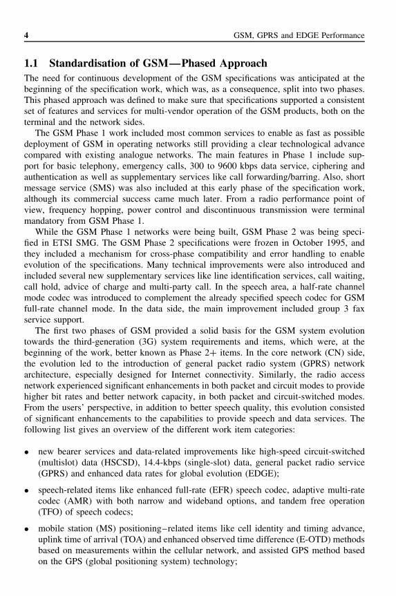
1.1 Standardisation of GSM—Phased ApproachThe need for continuous development of the GSM specifications was anticipated at thebeginning of the specification work, which was, as a consequence, split into two phases.This phased approach was defined to make sure that specifications supported a consistentset of features and services for multi-vendor operation of the GSM products, both on theterminal and the network sides.
The GSM Phase 1 work included most common services to enable as fast as possibledeployment of GSM in operating networks still providing a clear technological advancecompared with existing analogue networks. The main features in Phase 1 include sup-port for basic telephony, emergency calls, 300 to 9600 kbps data service, ciphering andauthentication as well as supplementary services like call forwarding/barring. Also, shortmessage service (SMS) was also included at this early phase of the specification work,although its commercial success came much later. From a radio performance point ofview, frequency hopping, power control and discontinuous transmission were terminalmandatory from GSM Phase 1.
While the GSM Phase 1 networks were being built, GSM Phase 2 was being speci-fied in ETSI SMG. The GSM Phase 2 specifications were frozen in October 1995, andthey included a mechanism for cross-phase compatibility and error handling to enableevolution of the specifications. Many technical improvements were also introduced andincluded several new supplementary services like line identification services, call waiting,call hold, advice of charge and multi-party call. In the speech area, a half-rate channelmode codec was introduced to complement the already specified speech codec for GSMfull-rate channel mode. In the data side, the main improvement included group 3 faxservice support.
The first two phases of GSM provided a solid basis for the GSM system evolutiontowards the third-generation (3G) system requirements and items, which were, at thebeginning of the work, better known as Phase 2+ items. In the core network (CN) side,the evolution led to the introduction of general packet radio system (GPRS) networkarchitecture, especially designed for Internet connectivity. Similarly, the radio accessnetwork experienced significant enhancements in both packet and circuit modes to providehigher bit rates and better network capacity, in both packet and circuit-switched modes.From the users’ perspective, in addition to better speech quality, this evolution consistedof significant enhancements to the capabilities to provide speech and data services. Thefollowing list gives an overview of the different work item categories:
• new bearer services and data-related improvements like high-speed circuit-switched(multislot) data (HSCSD), 14.4-kbps (single-slot) data, general packet radio service(GPRS) and enhanced data rates for global evolution (EDGE);
• speech-related items like enhanced full-rate (EFR) speech codec, adaptive multi-ratecodec (AMR) with both narrow and wideband options, and tandem free operation(TFO) of speech codecs;
• mobile station (MS) positioning–related items like cell identity and timing advance,uplink time of arrival (TOA) and enhanced observed time difference (E-OTD) methodsbased on measurements within the cellular network, and assisted GPS method basedon the GPS (global positioning system) technology;
GSM/EDGE Standards Evolution (up to Rel’4) 5
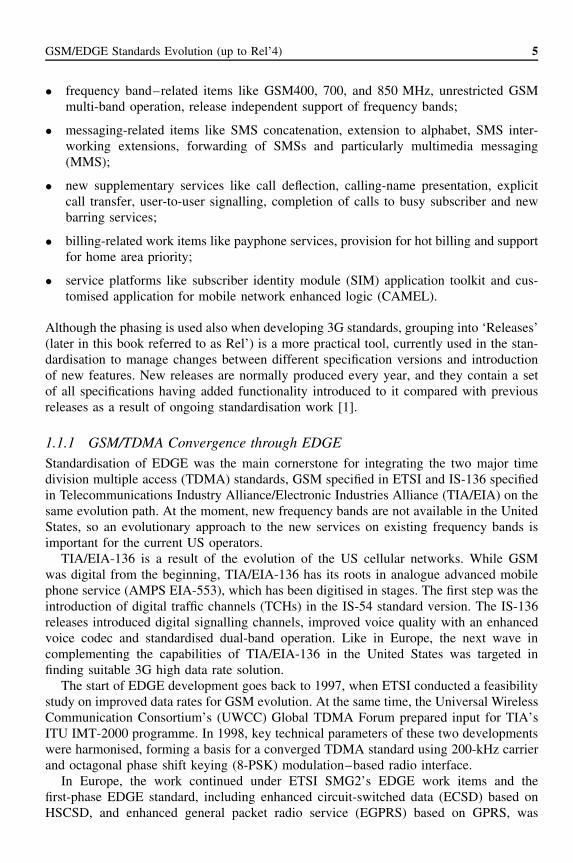
• frequency band–related items like GSM400, 700, and 850 MHz, unrestricted GSMmulti-band operation, release independent support of frequency bands;
• messaging-related items like SMS concatenation, extension to alphabet, SMS inter-working extensions, forwarding of SMSs and particularly multimedia messaging(MMS);
• new supplementary services like call deflection, calling-name presentation, explicitcall transfer, user-to-user signalling, completion of calls to busy subscriber and newbarring services;
• billing-related work items like payphone services, provision for hot billing and supportfor home area priority;
• service platforms like subscriber identity module (SIM) application toolkit and cus-tomised application for mobile network enhanced logic (CAMEL).
Although the phasing is used also when developing 3G standards, grouping into ‘Releases’(later in this book referred to as Rel’) is a more practical tool, currently used in the stan-dardisation to manage changes between different specification versions and introductionof new features. New releases are normally produced every year, and they contain a setof all specifications having added functionality introduced to it compared with previousreleases as a result of ongoing standardisation work [1].
1.1.1 GSM/TDMA Convergence through EDGEStandardisation of EDGE was the main cornerstone for integrating the two major timedivision multiple access (TDMA) standards, GSM specified in ETSI and IS-136 specifiedin Telecommunications Industry Alliance/Electronic Industries Alliance (TIA/EIA) on thesame evolution path. At the moment, new frequency bands are not available in the UnitedStates, so an evolutionary approach to the new services on existing frequency bands isimportant for the current US operators.
TIA/EIA-136 is a result of the evolution of the US cellular networks. While GSMwas digital from the beginning, TIA/EIA-136 has its roots in analogue advanced mobilephone service (AMPS EIA-553), which has been digitised in stages. The first step was theintroduction of digital traffic channels (TCHs) in the IS-54 standard version. The IS-136releases introduced digital signalling channels, improved voice quality with an enhancedvoice codec and standardised dual-band operation. Like in Europe, the next wave incomplementing the capabilities of TIA/EIA-136 in the United States was targeted infinding suitable 3G high data rate solution.
The start of EDGE development goes back to 1997, when ETSI conducted a feasibilitystudy on improved data rates for GSM evolution. At the same time, the Universal WirelessCommunication Consortium’s (UWCC) Global TDMA Forum prepared input for TIA’sITU IMT-2000 programme. In 1998, key technical parameters of these two developmentswere harmonised, forming a basis for a converged TDMA standard using 200-kHz carrierand octagonal phase shift keying (8-PSK) modulation–based radio interface.
In Europe, the work continued under ETSI SMG2’s EDGE work items and thefirst-phase EDGE standard, including enhanced circuit-switched data (ECSD) based onHSCSD, and enhanced general packet radio service (EGPRS) based on GPRS, was

6 GSM, GPRS and EDGE Performance
finalised in spring 2000. In addition, the specifications supported an optional arrangementcalled EDGE Compact, which enabled the deployment of EDGE in as narrow as 1-MHzfrequency bands.
In the United States, the work continued in TIA TR45 as further development of EDGEas part of the UWC-136 IMT-2000 proposal. In November 1999, the UWC-136 proposalwas approved as a radio interface specification for IMT-2000. Currently, EDGE is part ofthe GERAN development that is carried out concurrently in 3GPP and UWCC to ensurehigh synergy between GSM and TDMA systems in the future.
The latest developments in the US market from the two largest IS-136 operators, AT&Tand Cingular, define the mainstream evolution path likely to be followed by most IS-136operators. IS-136 networks will fully migrate to GSM/EDGE/WCDMA UMTS technol-ogy making use, in some cases, of the GAIT (GSM/ANSI-136 Interoperability Team)functionality to ensure a smooth migration [2]. As a result of this, EDGE Compact is notlikely to ever be implemented, since the evolution timing and the roaming requirementsdo not make this option interesting for operators.
1.1.2 GERAN Standardisation in 3GPP
In summer 2000, the specification work of GSM radio was moved from ETSI SMG2 to3GPP, which is a project responsible of the UMTS standards based on the evolved GSMcore network. This meant that Rel’99 was the last release of the GSM/EDGE standard thatwas specified in ETSI SMG, and all specifications related to GSM radio access networkwere moved under 3GPP responsibility with new specification numbers.
The moving of the specifications was motivated by both the need for improved workingprocedures and technical development closer to 3GPP. The core network part of the GSMspecifications was transferred to 3GPP by the time the project work was initiated, and thearrangement of standardising the GSM network and radio access parts in two differentstandardisation bodies made it too cumbersome to work effectively. More importantly,activities aimed at closer integration of GSM/EDGE radio and WCDMA technologieshad led to a decision to adopt the 3GPP-specific Iu interface for GERAN. Thereby, thisintegration achieves a true multi-radio UMTS standard, which is made up of two radiotechnologies, WCDMA and GSM/EDGE, that can be effectively and seamlessly integratedin order to maximise the efficiency and the quality of service provided to the end userswith the introduction of the coming 3G multimedia services.
1.1.2.1 3GPP Organisation
The 3GPP is a joint effort of several standardisation organisations around the worldtargeting to produce specifications for a global 3G cellular system. These so-called organ-isational partners (OPs) have the authority to develop standards in their region, and theycurrently include ETSI in Europe, Association of Radio Industries and Business (ARIB)in Japan, Standardisation Committee T1—Telecommunications (T1) in the United States,Telecommunication Technology Association (TTA) in Korea, China Wireless Telecom-munication Standard group (CWTS) in China and Telecommunications Technology Com-mittee (TTC) in Japan.
3GPP also have market representation partners (MRP), whose role is to make sure thatthe standardisation is in line with the market requirements. In practice, the MRPs work

GSM/EDGE Standards Evolution (up to Rel’4) 7
together with OPs in the Project Coordination Group (PCG) to guide the overall directionof the 3GPP work. Potential future partners can also follow the work as observers.
More information and up-to-date links about the 3GPP-related activities and organisa-tion can be found in http://www.3gpp.org/.
Most of the technical work in 3GPP is carried out by individual members, typically 3Goperators and vendors, in technical specification groups (TSGs) and their working groups(WGs). The basic 3GPP work organisation is depicted in Figure 1.1.
Currently there are five TSGs in 3GPP:
• TSG SA—Service and System Aspects, taking care of the overall system architectureand service capabilities, and cross TSG coordination on these areas. Issues related tosecurity, speech and multimedia codecs, network management and charging are alsohandled in SA.
• TSG CN—Core Network, taking care of the UMTS/GSM core network protocols.This includes the handling of layer 3 call control, mobility management and sessionmanagement protocols between the mobile terminal and CN, as well as inter-workingwith external networks.
• TSG T—Terminals, taking care of the aspects related to the terminal interfaces. Thisincludes the responsibility of issues like universal subscriber identity module (USIM),terminal equipment (TE) performance, service capability protocols, end-to-end serviceinter-working and messaging.
• TSG RAN—Radio Access Network, taking care of the aspects related to UMTS ter-restrial radio access network. This includes the handling of specifications for theWCDMA-based radio interface towards the WCDMA terminal, RAN-specific inter-faces Iub and Iur, and CN connectivity over Iu interface.
• TSG GERAN—GSM/EDGE Radio Access Network, taking care of the aspects relatedto the GSM/EDGE-based radio interface including testing for GERAN terminals,
Project co-ordination group (PCG)
TSG GERAN TSG RAN TSG core network TSG terminals
TSG SA—service &system aspects
WG1
WG2
WG3
WG4
WG5
Radio aspects
Protocols aspects
BTS testing
Terminal testing—radio part
Terminal testing—protocol part
3GPP
Figure 1.1. 3GPP organisation and TSG GERAN working groups

8 GSM, GPRS and EDGE Performance
GERAN internal interfaces as well as external interfaces related to the connectionstowards the legacy GSM CN.
TSGs have the mandate to approve and modify technical specifications in their area.Although TSGs are reasonably independent in terms of making decisions, liaising betweengroups is intended to ensure the technical consistency and timely finalisation of thespecifications for different releases. For TSG GERAN, this includes close cooperation,particularly with TSG SA on issues related to 3G bearer capabilities, architecture andsecurity, and with TSG RAN on issues related to the common interfaces (Iu, Iur) andprotocols (Packet Data Convergence Protocol (PDCP)) under TSG RAN responsibility,as well as overall optimisation of GSM/EDGE—WCDMA inter-operation.
While the TSGs carry the main responsibility for approval of the documents and overallwork coordination, the detailed level technical work takes place in WGs. In TSG GERAN,there are currently five WGs:
• WG1—Radio Aspects, specifically having the responsibility over the specificationsrelated to GSM/EDGE layer 1, radio frequency (RF), radio performance and inter-nal Ater specification between Channel Codec Unit (CCU) and Transcoder and RateAdapter Unit (TRAU).
• WG2—Protocols Aspects, specifically covering issues related to GERAN layer 2, likeradio link control (RLC)/medium access control (MAC) and three radio resource (RR)specifications, A and Gb interfaces towards 2G CN and internal Abis specificationbetween base station controller (BSC) and base transceiver station (BTS).
• WG3—Base Station Testing and O&M, taking care of all aspects related to confor-mance testing of GERAN BTSs, as well as GERAN-specific operation and mainte-nance issues for all GERAN nodes.
• WG4—Terminal Testing (Radio part), responsible for creating the specifications forthe conformance testing of GERAN terminals in the area of radio interface layer 1and RLC/MAC.
• WG5—Terminal Testing (Protocol part), responsible for creating the specificationsfor the conformance testing of GERAN terminals in the area of protocols aboveRLC/MAC.
1.2 Circuit-switched Services in GSMThe main drivers for the further development of the speech services and codecs arethe user demand for better speech quality and the capacity gains enabling cost savingsfor network operators. Enhanced full-rate codec was the first significant improvementin speech quality when it was introduced in ETSI specifications in 1996 as well as inIS-641 standards in the United States during the same year. While the old GSM half-rate(HR) and full-rate (FR) codecs lacked the quality of the wireline telephony (32-kbpsadaptive differential pulse code modulation (ADPCM)), EFR provided equivalent qualityas a normal fixed connection even in typical error conditions. The EFR codec was jointlydeveloped by Nokia and University of Sherbrooke and it has been widely used in operatingGSM networks worldwide.
GSM/EDGE Standards Evolution (up to Rel’4) 9
In spite of the commercial success of EFR, the codec left room for further improve-ments. In particular, the performance of the codec in severe radio channel error conditionscould have been better. In addition to this, GSM half-rate codec was not able to provideadequate speech quality, so it was decided to continue the codec specification work witha new codec generation [3].
1.2.1 Adaptive Multi-rate Codec (AMR)
In October 1997, a new programme was initiated in ETSI, aimed at the developmentand standardisation of AMR for GSM system. Before the standardisation was officiallystarted, a one-year feasibility study was carried out to validate the AMR concept. Themain target of the work was to develop a codec that provided a significant improvementin error robustness, as well as capacity, over EFR.
The actual AMR codec standardisation was carried out as a competitive selectionprocess consisting of several phases. In February 1999, ETSI approved the AMR codecstandard, which was based on the codec developed in collaboration between Ericsson,Nokia and Siemens. Two months later, 3GPP adopted the AMR codec as the mandatoryspeech codec for the 3G WCDMA system. Some parts of the AMR codec work, such asvoice activity detection (VAD) and optimised channel coding were finalised and includedin the standard later, in June 1999.
The AMR codec contains a set of fixed-rate speech and channel codecs, fast in-bandsignalling and link adaptation. The AMR codec operates both in the full-rate (22.8 kbps)and half-rate (11.4 kbps) GSM channel modes. An important part of AMR is its ability toadapt to radio channel and traffic load conditions and select the optimum channel mode(HR or FR) and codec mode (bit rate trade-off between speech and channel coding) todeliver the best possible combination of speech quality and system capacity.
Even though the AMR codec functionality is not mandatory in Rel’98-compliant ter-minals, the large benefits this functionality will bring will probably drive the demand forthe support of AMR codec in all terminals.
1.2.1.1 Speech and Channel Coding
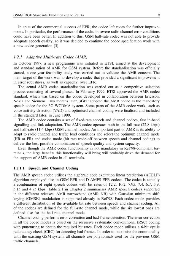
The AMR speech codec utilises the algebraic code excitation linear prediction (ACELP)algorithm employed also in GSM EFR and D-AMPS EFR codecs. The codec is actuallya combination of eight speech codecs with bit rates of 12.2, 10.2, 7.95, 7.4, 6.7, 5.9,5.15 and 4.75 kbps. Table 2.1 in Chapter 2 summarises AMR speech codecs supportedin the different releases. AMR narrowband (AMR NB) with Gaussian minimum shiftkeying (GMSK) modulation is supported already in Rel’98. Each codec mode providesa different distribution of the available bit rate between speech and channel coding. Allof the codecs are defined for the full-rate channel mode, while the six lowest ones aredefined also for the half-rate channel mode.
Channel coding performs error correction and bad-frame detection. The error correctionin all the codec modes is based on the recursive systematic convolutional (RSC) codingwith puncturing to obtain the required bit rates. Each codec mode utilises a 6-bit cyclicredundancy check (CRC) for detecting bad frames. In order to maximise the commonalitywith the existing GSM system, all channels use polynomials used for the previous GSMtraffic channels.

10 GSM, GPRS and EDGE Performance
1.2.1.2 In-band Signalling and Link Adaptation
In the basic AMR codec operation, shown in Figure 1.2, both the mobile station (MS)and the base transceiver station (BTS) perform channel quality estimation of the receivedsignal. On the basis of the channel quality measurements, a codec mode command (down-link to the MS) or codec mode request (uplink to the BTS) is sent over the radio interfacein in-band messages. The receiving end uses this information to choose the best codecmode for the prevailing channel condition. A codec mode indicator is also sent over theradio to indicate the current mode of operation in the sending side. The basic principle forthe codec mode selection is that the mode chosen in the uplink may be different from theone used in the downlink direction, but the channel mode (HR or FR) must be the same.
The benefit of the in-band method is that it does not require a separate signallingchannel for the message transfer. By sending the messages and the indicators togetherwith the speech payload, the link adaptation operation can also be made faster, leadingto improvements in the system performance.
The network controls the uplink and the downlink codec modes and channel modes.The MS must obey the codec mode command from the network, while the network mayuse any complementing information, in addition to codec mode request, to determinethe downlink codec mode. The MS must implement all the codec modes. However, thenetwork can support any combination of them, on the basis of the choice of the operator.
AMR also contains voice activity detection and discontinuous transmission(VAD/DTX). These are used to switch off the encoding and transmission during periodsof silence, thereby reducing radio interference and extending the battery lifetime.
S - speech dataQI - quality indicatorMC - codec mode commandMR - codec mode requestMI - codec mode indicator
(inband signalling)(inband signalling)(inband signalling)
u = Uplinkd = Downlink
Mobile station (MS) Base tranceiver station (BTS) Transcoder (TC)
Speechin
Speechout
Speechin
Speechout
Multi-rate
speechencoder
Multi-rate
channeldecoder
Multi-rate
channelencoder
Multi-rate
speechencoder
Multi-rate
speechdecoder
Multi-rate
speechdecoder
Moderequest
generator
Downlinkqualitymeas.
Multi-rate
channelencoder
Multi-rate
channeldecoder
MIu
MCu
MCd
MCd
MCu MCu MCu
MIu MIu
MId MIdMId
MIu Abis/ter
Abis/ter
MIu
MIu
MRd MRd
MRd MRd
s
s s ss
s s s s
Link
ada
ptat
ion
Radiochannel(uplink)
Radiochannel
(downlink)
Uplinkqualitymeas.
Downlinkmodecontrol
Uplinkmodecontrol
Networkconstraints
Linkadaptation
(Network)
TC
QIu
QIu
Figure 1.2. Block diagram of the AMR codec system

GSM/EDGE Standards Evolution (up to Rel’4) 11
1.2.2 High Speech Circuit-switched Data (HSCSD)
The first-phase GSM specifications provided only basic transmission capabilities for thesupport of data services, with the maximum data rate in these early networks being limitedto 9.6 kbps on one timeslot. HSCSD specified in Rel’96 was the first GSM Phase 2+ workitem that clearly increased the achievable data rates in the GSM system. The maximumradio interface bit rate of an HSCSD configuration with 14.4-kbps channel coding is115.2 kbps, i.e. up to eight times the bit rate on the single-slot full-rate traffic channel(TCH/F). In practice, the maximum data rate is limited to 64 kbps owing to core networkand A-interface limitations.
The main benefit of the HSCSD feature compared to other data enhancements intro-duced later is that it is an inexpensive way to implement higher data rates in GSM networksowing to relatively small incremental modifications needed for the network equipment.Terminals, however, need to be upgraded to support multislot capabilities. The basicHSCSD terminals with relatively simple implementation (in size and cost compared to asingle-slot terminal) available in the market today can receive up to four and transmit upto two timeslots and thus support data rates above 50 kbps. Figure 1.3 depicts the HSCSDnetwork architecture based on the concept of multiple independent TCH/F channels.
In HSCSD, a new functionality is introduced at the network and terminals to providethe functions of combining and splitting the user data into separate n data streams, whichwill then be transferred via n channels at the radio interface, where n = 1, 2, 3, . . ., 8.Once split, the data streams shall be carried by the n full-rate traffic channels, calledHSCSD channels, as if they were independent of each other, for the purpose of datarelay and radio interface L1 error control, until the point in the network where they arecombined. However, logically the n full-rate traffic channels at the radio interface belongto the same HSCSD configuration, and therefore they shall be controlled as one radio linkby the network for the purpose of cellular operations, e.g. handover.
For both transparent and non-transparent HSCSD connections, the call can be estab-lished with any number of TCH/F from one up to the maximum number of TCH/F, i.e.the minimum channel requirement is always one TCH/F.
If the wanted air interface user rate requirement cannot be met using a symmetricconfiguration, an asymmetric configuration can be chosen. The network shall, in this case,give priority to fulfilling the air interface user rate requirement in the downlink direction.
MS BTS BSC MSC
Air I/F Abis I/F A I/F
TAF
IWF
n full-rate channelsor n time slots per TDMA frame 1 circuit maximum
Figure 1.3. Network architecture for supporting HSCSD

12 GSM, GPRS and EDGE Performance
The MS may request a service level upgrading or downgrading during the call, if sonegotiated in the beginning of the call. This modification of channel requirements and/orwanted air interface user rate is applicable to non-transparent HSCSD connections only.
1.2.2.1 Radio Interface
Two types of HSCSD configurations exist: symmetric and asymmetric. For both types ofconfigurations, the channels may be allocated on either consecutive or non-consecutivetimeslots, taking into account the restrictions defined by the mobile station’s multislotclasses, described in detail in [2]. An example of the HSCSD operation with two consec-utive timeslots is shown in Figure 1.4.
A symmetric HSCSD configuration consists of a co-allocated bi-directional TCH/Fchannel. An asymmetric HSCSD configuration consists of a co-allocated uni-directionalor bi-directional TCH/F channel. A bi-directional channel is a channel on which the dataare transferred in both uplink and downlink directions. On uni-directional channels forHSCSD, the data are transferred in downlink direction only. The same frequency-hoppingsequence and training sequence is used for all the channels in the HSCSD configuration.
In symmetric HSCSD configuration, individual signal level and quality reporting foreach HSCSD channel is applied. For an asymmetric HSCSD configuration, individualsignal level and quality reporting is used for those channels. The quality measurementsreported on the main channel are based on the worst quality measured among the main andthe uni-directional downlink timeslots used. In both symmetric and asymmetric HSCSDconfiguration, the neighbouring cell measurement reports are copied on every uplinkchannel used. See [4] for more detail on signal level and quality reporting.
Transparent Data Transmission
In transparent data transmission, the V.110 data frames on the HSCSD channels carrydata sub-stream numbers to retain the order of transmission over GSM, between thesplit/combine functions. Between these functions, channel internal multiframing is alsoused in order to increase the tolerance against inter-channel transmission delays. Depend-ing on the location of the access point to external networks, the split/combine functionalityis located at the base station sub-system (BSS) or in the IWF on the network side, and atthe MS.
Non-transparent Data Transmission
Non-transparent mode of HSCSD is realised by modifying the radio link protocol (RLP)and L2R functions to support multiple parallel TCH/Fs instead of only one TCH/F
0 107654321MS RX
5 654321076MS TX
Monitor
Figure 1.4. Double-slot operation in the air interface

GSM/EDGE Standards Evolution (up to Rel’4) 13
MS IWF
L1 entity
L1 entity
L1 entity
L1 entity
L1 entity
L1 entity
L2RHSCSD
RLPHSCSD
RLP L2R
Figure 1.5. The HSCSD concept in non-transparent mode
(Figure 1.5). In addition, the RLP frame numbering is increased to accommodate theenlarged data-transmission rate.
1.3 Location ServicesDifferent positioning methods found the basis for providing location services (LCS) in theGSM system. In general, these services can be implemented by using vendor-/operator-specific or standardised solutions. Both of these methods and their combination are likelyto be used when LCS enter the operating networks.
The vendor-/operator-specific solutions utilise the information already available in thecellular network or measured by proprietary units installed for this purpose. The userlocation is thus estimated by combining and processing the available information withthe help of tools and algorithms implemented for this purpose. In the standardised solu-tion, the basic difference compared to the specific one is that the functionalities andcapabilities required to retrieve the information for positioning are integrated into thesystem itself. The integrated solution affects the specifications and thus standardisationeffort is needed, but benefit of this approach is that it enables multi-vendor support andprovides a complete support for user privacy. In this chapter, a short overview of thehistory and drivers behind the standardisation of the location services is given. Chapter 4describes in more detail the positioning methods, architecture and main technical princi-ples behind them.
1.3.1 LCS Standardisation ProcessThe LCS standardisation began in ETSI SMG in 1995 after European operators asked forcommercial services and separately in T1P1 in the United States after Federal Communi-cations Commission (FCC) established the E911 requirements for the E911 service. TheE911 requirement stated that by October 1, 2001, US operators must be able to locate thesubscriber calling the emergency number 911.
However, several operators have applied and received waivers for the E911 require-ments, and in spite of the different drivers behind the work in the United States andEurope, T1P1.5 (T1P1 is a subgroup of T1, a committee of TIA, the North AmericanTelecommunications Industry Association) was given the responsibility to lead the overallstandardisation activities in 1997. Four location methods were proposed and taken to thestandardisation process:
• cell identity and timing advance;
• uplink time of arrival (TOA);

14 GSM, GPRS and EDGE Performance
• enhanced observed time difference (E-OTD) methods based on measurements withinthe cellular network; as well as
• assisted GPS method based on the GPS technology.
In spring 1999, all four methods were included in the GSM specifications Rel’98 andRel’99, including changes to GSM architecture and introduction of several new networkelements for LCS purposes. Later in 2001, TOA method was excluded from the Rel’4specifications because no commercial support for the scheme was foreseen because of thecomplexity in implementing the method in operating networks.
The first specification versions (Rel’98, Rel’99 and Rel’4) include the LCS supportfor circuit-switched connections over the A-interface towards the 2G CN only. In Rel’5,the focus is then moved towards providing the same LCS support in puncturing scheme(PS) domain connections over Gb and Iu interfaces. The main reasons for this gradualintroduction of different modes were not only the regulatory requirements that, in practice,were applicable for coding scheme (CS) speech connections only but also the delays inthe introduction of GPRS and its interfaces. When the penetration of GPRS users andterminals increases, LCS is expected to be more and more an attractive increment to theservices provided to the GPRS subscribers in ‘always connected’ mode.
1.4 General Packet Radio System (GPRS)
1.4.1 Introduction of GPRS (Rel’97)
Soon after the first GSM networks became operational in the early 1990s and the use ofthe GSM data services started, it became evident that the circuit-switched bearer serviceswere not particularly well suited for certain types of applications with a bursty nature. Thecircuit-switched connection has a long access time to the network, and the call charging isbased on the connection time. In packet-switched networks, the connections do not reserveresources permanently, but make use of the common pool, which is highly efficient, inparticular, for applications with a bursty nature. The GPRS system will have a very shortaccess time to the network and the call charging could solely be based on an amount oftransmitted data.
The GPRS system brings the packet-switched bearer services to the existing GSMsystem. In the GPRS system, a user can access the public data networks directly using theirstandard protocol addresses (IP, X.25), which can be activated when the MS is attachedto the GPRS network. The GPRS MS can use between one and eight channels over the airinterface depending on the MS capabilities, and those channels are dynamically allocatedto an MS when there are packets to be sent or received. In the GPRS network, uplink anddownlink channels are reserved separately, making it possible to have MSs with variousuplink and downlink capabilities. The resource allocation in the GPRS network is dynamicand dependent on demand and resource availability. Packets can also be sent on idle timebetween speech calls. With the GPRS system, it is possible to communicate point-to-point(PTP) or point-to-multipoint (PTM); it also supports the SMS and anonymous access tothe network. The theoretical maximum throughput in the GPRS system is 160 kbps perMS using all eight channels without error correction.

GSM/EDGE Standards Evolution (up to Rel’4) 15
1.4.2 GPRS Network ArchitectureIn Figure 1.6, a functional view of the GPRS network is displayed. GPRS brings a few newnetwork elements to the GSM network. The most important ones are the serving GPRSsupport node (SGSN) and the gateway GPRS support node (GGSN). Another importantnew element is the point-to-multipoint service centre (PTM-SC), which is dedicated to thePTM services in the GPRS network. Another new network element is the border gateway(BG), which is mainly needed for security reasons and is situated on the connection to theinter-PLMN backbone network. The inter-PLMN and intra-PLMN backbone networks arealso new elements, both Internet protocol–based (IP-based) networks. In addition, therewill be a few new gateways in the GPRS system like the charging gateway and the legalinterception gateway.
While the current GSM system was originally designed with an emphasis on voicesessions, the main objective of the GPRS is to offer an access to standard data networkssuch as transport control protocol (TCP)/Internet protocol (IP) and X.25. These othernetworks consider GPRS just as a normal sub-network (Figure 1.7). A GGSN in theGPRS network behaves as a router and hides the GPRS-specific features from the externaldata network.
The mobile user can have either a static or a dynamic data network address, and thedata traffic will always use the gateway indicated by this address (Figure 1.8). However,the home network operator could force all the traffic to use a home GGSN, for example,for security reasons.
A static address is permanently allocated for one subscriber. As it will point to agateway of the home network, the data packets will always be routed through the homenetwork. Figure 1.8 illustrates the case where a user is in his home network (case 1) andin a visited network (case 2).
Inter-PLMNbackbonenetwork
R/S UmBTS
BSC
MSC
PSTN
Gb
GPRSinfrastructure
Gn
GrGr HLR/AuC
EIR
GdGd
Gs
Gs
Serving GPRSsupport node(SGSN)
Bordergateway (BG)
GpFirewall
Firewall
Point-to-multipointservicecenter(PTM SC)
Gateway GPRSsupport node(GGSN)
Gn
Datanetwork(X.25)
Datanetwork(Internet)
MAP-F
SS7Network
RouterLocalareanetwork
Intra-PLMNbackbonenetwork(IP based)
Gi.X.25
Gi.IPCorporate 2
Corporate 1
Server
Server
SMS-GMSC
RouterLocalareanetwork
Figure 1.6. Functional view of GPRS

16 GSM, GPRS and EDGE Performance
Host155.222.33.55
Host191.200.44.21
Host131.44.15.3
Sub-network191.200.44.xxx
Sub-network155.222.33.xxx
Sub-network131.44.15.xxx
Corporate 1
Router
Router
“Router”
Localareanetwork
Localareanetwork
Datanetwork(Internet)
Corporate 2
GPRSsub-network
Figure 1.7. GPRS network seen by another data network
Case 1Case 3
Case 2
GPRSbackbonenetwork(IP based)
Inter-operatorbackbonenetwork
Datanetwork(internet)
SGSNSGSN
GGSN GGSN
IProuter
IProuter
VisitedGPRSnetwork
GPRSbackbonenetwork(IP based)
BTS BSC BTSBSC
HOME GPRSNETWORK
Router Localareanetwork
Server
Corporate
Figure 1.8. Data transfer
Each network can also have a pool of available addresses that can be allocated dynam-ically to the users by the GGSN. This decreases the number of addresses needed by anoperator. A dynamic address is allocated to a user only for the time of a connection. Toavoid routing the packet through the home network, the dynamic address can be allocatedby a GGSN from the visited network (case 3 in Figure 1.8). It can also be allocated by aGGSN from the home network (case 2) to apply, for example, some specific screening.

GSM/EDGE Standards Evolution (up to Rel’4) 17
The incoming and outgoing PTP traffic can be charged on the basis of the quantity ofdata transmitted, the protocol used, the length of connection, etc.
1.4.2.1 GPRS Mobiles
A GPRS MS can operate in one of three modes of operation (Table 1.1):
• Class A mode of operation. The MS is attached to both GPRS and other GSM services.The mobile user can make and/or receive calls on the two services simultaneously,subject to the quality of service (QoS) requirements, e.g. having a normal GSM voicecall and receiving GPRS data packets at the same time.
• Class B mode of operation. The MS is attached to both GPRS and other GSM ser-vices, but the MS can only operate one set of services at a time. The MS in idlemode (and packet idle mode) is required to monitor paging channels (PCHs) for bothcircuit-switched and packet-switched services. However, the practical behaviour of theMS depends on the mode of network operation. For example, one mode of networkoperation is defined so that when an MS is engaged in packet data transfer, it willreceive paging messages via the packet data channel (PDCH) without degradation ofthe packet data transfer.
• Class C mode of operation. The MS can only be attached to either the GSM networkor the GPRS network. The selection is done manually and there are no simultane-ous operations.
In GSM Phase 2, the MS uses one channel for the uplink traffic and one channel forthe downlink traffic (Figure 1.9, ‘1-slot’). In GPRS, it is possible to have a multiple slotMS, e.g. a 2-slot MS with two uplink channels and two downlink channels (Figure 1.9,‘2-slot’). The MS can have a different (asymmetric) uplink and downlink capability.
When an MS supports the use of multiple timeslots, it belongs to a multislot class asdefined in [5]. Multislot class is defined as a combination of several parameters:
• The maximum number of received timeslots that the MS can use per TDMA frame.
• The maximum number of transmit timeslots that the MS can use per TDMA frame.
• Total number of uplink and downlink timeslots that can actually be used by the MSper TDMA frame.
• The time needed for the MS to perform adjacent cell signal level measurement andget ready to transmit (Tta).
• The time needed for the MS to get ready to transmit (Ttb).
Table 1.1. GPRS mobile classes
Class A mode of operation Class B mode of operation Class C mode of operation
Full simultaneous use ofpacket and circuit modeconnections
No simultaneous traffic butautomatic sequential service
Alternate use or aGPRS-only MS

18 GSM, GPRS and EDGE Performance
1-slot
2-slot
Downlink
Uplink
Monitor
Downlink
Uplink
Monitor
Downlink
Uplink
Monitor
0
0
0
1
1
2
2
3
3
4
4
5
55
6
66
7
7
0 1
0
1
1 2
2 3
3
4
4
5
55 6 7
6
6
7 0 1
0
0
1
1 2
2 5
55 6 7
6
6
7 0 1
3–8-slot
3 slots: 4th slot: 5th slot:
3 4
3 4
Figure 1.9. GPRS multislot capabilities
• The time needed for the MS to perform adjacent cell signal level measurement andget ready to receive (Tra).
• The time needed for the MS to get ready to receive (Trb).
• Capability to receive and transmit at the same time. There are two types of MS:
• Type 1: The MS is not required to transmit and receive at the same time.• Type 2: The MS is required to transmit and receive at the same time.
A combination of these factors has led to a definition of 29 MS classes (in Rel’97 ofGSM specifications). Most of the GPRS terminals (if not all) are type 1 owing to thesimpler radio design. Table 1.2 shows the multislot classes. A complete multislot classestable (including Type 2 terminals) can be found in Annex B of [5].
1.4.2.2 Base Station Sub-system (BSS)
The BSS is upgraded with new GPRS protocols for the Gb interface (between the BSS andSGSN) and enhanced layer 2 (RLC/MAC see the section entitled Medium access controland radio link control layer) protocols for the air interface. The Gb interface connectsthe BSS and the SGSN, allowing the exchange of signalling information and user data.Both air and Gb interfaces allow many users to be multiplexed over the same physicalresources. The BSS allocates resources to a user upon activity (when data are sent orreceived) and the data are reallocated immediately thereafter. The Gb interface link layeris based on frame relay, which is used for signalling and data transmission. The basestation sub-system GPRS protocol (BSSGP) provides the radio-related QoS and routinginformation that is required to transmit user data between a BSS and an SGSN.

GSM/EDGE Standards Evolution (up to Rel’4) 19
Table 1.2. Type 1 multislot classes
Maximum number of slots Minimum number of slots
Multislot class Rx Tx Sum Tta Ttb Tra Trb
1 1 1 2 3 2 4 22 2 1 3 3 2 3 13 2 2 3 3 2 3 14 3 1 4 3 1 3 15 2 2 4 3 1 3 16 3 2 4 3 1 3 17 3 3 4 3 1 3 18 4 1 5 3 1 2 19 3 2 5 3 1 2 1
10 4 2 5 3 1 2 111 4 3 5 3 1 2 112 4 4 5 2 1 2 1
1.4.2.3 Mobile Services Switching Centre/Home Location Register (MSC/HLR)
The HLR is upgraded and contains GPRS subscription data. The HLR is accessible fromthe SGSN via the Gr interface and from the GGSN via the optional Gc interface. Forroaming MSs, HLR is in a different public land mobile network (PLMN) than the currentSGSN. All MSs use their HLR in home public land mobile network (HPLMN). The HLRis enhanced with GPRS subscriber information.
The MSC/visiting location register (VLR) can be enhanced for more efficient coordina-tion of GPRS and non-GPRS services and functionality by implementing the Gs interface,which uses the BSSAP+ procedures, a subset of BSS application part (BSSAP) proce-dures. Paging for circuit-switched calls can be performed more efficiently via the SGSN.This is the case as well for the combined GPRS and non-GPRS location updates. The Gsinterface also allows easy Class B mode of operation for MS design. The SMS-GMSC andSMS-IWMSC functions are enhanced for SMS over GPRS. Also, the temporary mobilesubscriber identity (TMSI) allocation procedure is modified.
1.4.2.4 SGSN
The SGSN is a main component of the GPRS network, which handles, e.g. the mobilitymanagement and authentication and has register function. The SGSN is connected tothe BSC and is the service access point to the GPRS network for the GPRS MS. TheSGSN handles the protocol conversion from the IP used in the backbone network to thesub-network-dependent convergence protocol (SNDCP) and logical link control (LLC)protocols used between the SGSN and the MS. These protocols handle compression andciphering. The SGSN also handles the authentication of GPRS mobiles, and when theauthentication is successful, the SGSN handles the registration of an MS to the GPRSnetwork and takes care of its mobility management. When the MS wants to send (orreceive) data to (from) external networks, the SGSN relays the data between the SGSNand relevant GGSN (and vice versa).

20 GSM, GPRS and EDGE Performance
1.4.2.5 GGSN
The GGSN is connected to the external networks like the Internet and the X.25. From theexternal networks’ point of view, the GGSN is a router to a sub-network, because theGGSN ‘hides’ the GPRS infrastructure from the external networks. When the GGSNreceives data addressed to a specific user, it checks if the address is active. If it is, theGGSN forwards the data to the SGSN serving the MS, but if the address is inactive, thedata are discarded. The mobile-originated packets are routed to the right network bythe GGSN. The GGSN tracks the MS with a precision of SGSN.
1.4.3 GPRS Interfaces and Reference Points
The GPRS system introduces new so-called G-interfaces to the GSM network architecture.It is important to understand the function of every interface and reference point becausethis gives an insight to the GPRS system and consequent evolution. Figure 1.10 givesa logical architecture description with the interfaces and reference points of the GSMnetwork with GPRS.
Connections of the GPRS system to the network and switching sub-system (NSS) partof the GSM network are implemented through signalling system number 7 (SS7) network(Gc, Gd, Gf, Gr, Gs), while the other interfaces and reference points are implementedthrough the intra-PLMN backbone network (Gn), the inter-PLMN backbone network(Gp) or the external networks (Gi). The different interfaces that the GPRS system usesare as follows:
SMS-GMSCSMS-IWMSC SM-SC
E
TETE MT BSS
A
PDN
Gs
Gd
Gb
Gp GfGnUmR
GrGc
Gi
Gn
C
MSC/VLR HLR
EIR
GGSN
GGSNSGSN
SGSN
Other PLMN
D
Signalling interface
Signalling and data transfer interface
Figure 1.10. Logical architecture

GSM/EDGE Standards Evolution (up to Rel’4) 21
• Gb between an SGSN and a BSS. The Gb interface is the carrier of the GPRS trafficand signalling between the GSM radio network (BSS) and the GPRS part. Framerelay–based network services (NSs) provide flow control for this interface.
• Gc between the GGSN and the HLR. The GGSN may request location information fornetwork-requested context activation only via this optional interface. The standard alsodefines the use of a proxy GSN, which is used as a GPRS tunnelling protocol (GTP) tomobile application part (MAP) protocol converter, thus avoiding implementing MAPin GGSN.
• Gd between the SMS-GMSC and an SGSN, and between SMS-IWMSC and an SGSN.The Gd interface allows more efficient use of the SMS services.
• Gf between an SGSN and the Equipment Identity Register (EIR). The Gf gives theSGSN access to equipment information. In the EIR, the MSs are divided into threelists: black list for stolen mobiles, grey list for mobiles under observation and whitelist for other mobiles.
• Gn between two GSNs within the same PLMN. The Gn provides a data and signallinginterface in the intra-PLMN backbone. The GTP is used in the Gn (and in the Gp)interface over the IP-based backbone network.
• Gp between two GSNs in various PLMNs. The Gp interface provides the same func-tionality as the Gn interface, but it also provides, with the BG and the Firewall, allthe functions needed in the inter-PLMN networking, i.e. security, routing, etc.
• Gr between an SGSN and the HLR. The Gr gives the SGSN access to subscriberinformation in the HLR, which can be located in a different PLMN than the SGSN.
• Gs between an SGSN and an MSC. The SGSN can send location data to the MSCor receive paging requests from the MSC via this optional interface. The Gs interfacewill greatly improve effective use of the radio and network resources in the combinedGSM/GPRS network. This interface uses BSSAP+ protocol.
• Um between a MS and the GPRS fixed network part. The Um is the access interfacefor the MS to the GPRS network. The MS has a radio interface to the BTS, which is thesame interface used by the existing GSM network with some GPRS-specific changes.
There are two different reference points in the GPRS network. The Gi is GPRS-specific,but the R is common with the circuit-switched GSM network. The two reference pointsin the GPRS are as follows:
• Gi between a GGSN and an external network. The GPRS network is connected toexternal data networks via this interface. The GPRS system will support a varietyof data networks and that is why the Gi is not a standard interface, but merely areference point.
• R between terminal equipment and mobile termination. This reference point connectsterminal equipment to mobile termination, thus allowing, e.g. a laptop-PC to transmitdata over the GSM phone. The physical R interface follows, e.g. the ITU-T V.24/V.28or the PCMCIA PC-Card standards.

22 GSM, GPRS and EDGE Performance
1.4.4 GPRS Protocol ArchitectureThe GPRS system introduces a whole new set of protocols for the GSM Phase 2+ network.The inter-working between the new network elements is done with new GPRS-specificprotocols. However, there are a number of existing protocols used at the lower layers ofthe protocol stacks, namely, TCP/user datagram protocol (UDP) IP. Figure 1.11 showsthe transmission plane used in the GPRS system.
1.4.4.1 Physical Layer
The physical layer has been separated into two distinct sub-layers, the physical RF layerand the physical link layer.
The physical RF layer performs the modulation of the physical waveforms basedon the sequence of bits received from the physical link layer. The physical RF layeralso demodulates received waveforms into a sequence of bits that are transferred to thephysical link layer for interpretation. The GSM physical RF layer is defined in GSM 05series specifications, which define the following among other things:
• The carrier frequency characteristics and GSM radio channel structures [5].
• The modulation of the transmitted waveforms and the raw data rates of GSM chan-nels [6]. Note that in the GPRS Rel’97 radio interface, only the original GSM modu-lation method, GMSK modulation, with the carrier bit rate of 270.833 kbps is defined.For one single timeslot, this corresponds to the gross data rate of 22.8 kbps.
• The transmitter and receiver characteristics and performance requirements [7].
• The physical link layer provides services for information transfer over a physicalchannel between the MS and the network. These functions include data unit framing,data coding and the detection and correction of physical medium transmission errors.The physical link layer operates above the physical RF layer to provide a physicalchannel between the MS and the network. The purpose of the physical link layer is to
Application
Relay
Relay
IP/X.25
SNDCP
LLC
SNDCP
LLC
RLC
MAC
GSM RF
RLC
MAC
GSM RF
BSSGP
Networkservices
L1bis
BSSGP
Networkservices
L1bis
GTP
UDP/TCP
IP
L2
L1
IP/X.25
BSS SGSNMS GGSN
Gb GnUm Gi
GTP
UDP/TCP
IP
L2
L1
Figure 1.11. Transmission plane

GSM/EDGE Standards Evolution (up to Rel’4) 23
convey information across the GSM radio interface, including RLC/MAC information.The physical link layer supports multiple MSs sharing a single physical channel andprovides communication between MSs and the network. In addition, it provides theservices necessary to maintain communications capability over the physical radiochannel between the network and MSs. Radio sub-system link control procedures arespecified in [4].
The physical link layer is responsible for the following:
• Forward error correction (FEC) coding, allowing the detection and correction of trans-mitted code words and the indication of uncorrectable code words. The coding schemesare described in the section entitled Physical link layer.
• Rectangular interleaving of one radio block over four bursts in consecutive TDMAframes, as specified in [8].
• Procedures for detecting physical link congestion.
The physical link layer control functions include
• synchronisation procedures, including means for determining and adjusting the MStiming advance to correct for variances in propagation delay [9],
• monitoring and evaluation procedures for radio link signal quality.
• cell selection and re-selection procedures.
• transmitter power control procedures.
• battery power saving procedures, e.g. discontinuous reception (DRX) procedures.
For more details, see the section entitled Physical link layer.
1.4.4.2 RLC/MAC
The RLC/MAC layer provides services for information transfer over the physical layer ofthe GPRS radio interface. These functions include backward error correction proceduresenabled by the selective re-transmission of erroneous blocks. The RLC function offers areliable radio link to the upper layers. The MAC function handles the channel allocationand the multiplexing, i.e. the use of physical layer functions. The RLC/MAC layer togetherform the open system interconnection (OSI) Layer 2 protocol for the Um interface anduses the services of the physical link layer (see the section entitled Medium Access Controland Radio Link Control Layer).
1.4.4.3 LLC
The logical link control layer offers a secure and reliable logical link between the MS andthe SGSN to upper layers, and is independent of the lower layers. The LLC layer has twotransfer modes—the acknowledged and unacknowledged. The LLC conveys signalling,SMS and SNDCP packets. See [10] for more information.

24 GSM, GPRS and EDGE Performance
1.4.4.4 SNDCP
The sub-network-dependent convergence protocol (SNDCP) is a mapping and compressionfunction between the network layer and lower layers. It also performs segmentation,reassembling and multiplexing. The SNDCP protocol is specified in [11].
Signalling has various sets of protocols, which are used with the existing GSM networkelements. Internal signalling in the GPRS system is handled by protocols, which carryboth data and signalling (LLC, GTP and BSSGP). The GPRS control plane is shown inFigure 1.12.
Figure 1.13 describes how network protocols are multiplexed. NSAPI is the networklayer service access point identifier, which is used to identify the packet data protocol(PDP) context at SNDCP level. Service access point identifier (SAPI) is used to identifythe points where LLC provides service to higher layers. SAPIs have different priorities.TLLI is the temporary logical link identity, which unambiguously identifies the logicallink between the MS and the SGSN. The IP or the X.25 is the packet protocol offered tothe subscriber by the GPRS system.
1.4.4.5 BSSGP
The primary functions of the base station sub-system GPRS protocol (BSSGP) (see [12])include, in the downlink, the provision by an SGSN to a BSS of radio-related informationused by the RLC/MAC function; in the uplink, the provision by a BSS to an SGSNof radio-related information derived from the RLC/MAC function; and the provision offunctionality to enable two physically distinct nodes, an SGSN and a BSS, to operatenode management control functions. See [12] for more details. The underlying networkservice is responsible for the transport of BSSGP packet data units (PDUs) between aBSS and an SGSN [12].
MS
GMM/SM
GMM/SM
LLC
RLC
MAC
RF
LLC RELAY
BSS
SGSN
RLC
MAC
RF
BSSGP
NS
FR
L1
LLC
BSSGP
NS
FR
L1
GTP
UDP
IP
L2
L1
GTP
SGSN
UDP
IP
L2/L1
L1TCAP
MAP
SCCP
MTP
BSSAP+
SCCP
MTPGr
Gs
Gn/Gp
GbUm SS#7
IP-NET
TCAP
MAP
HLR
SCCP
MTP
BSSAP+
SCCP
MSC/VLR
MTP
GTP
GGSN
UDP
IP
L2/L1
L1
Figure 1.12. GPRS control plane

GSM/EDGE Standards Evolution (up to Rel’4) 25
Signalling
SAPI
TLLI
NSAPI
LLC
RLC or BSSGP
SNDCP
N-PDU
Packet dataprotocolSMS
NSAPI + control Data
SNDC header
Control Data
LLC informationLLC header
Figure 1.13. Multiplexing of network protocols
1.4.4.6 GTP
The GPRS tunnelling protocol (GTP) is used to tunnel data and signalling between theGSNs. The GTP can have proprietary extensions to allow proprietary features. The relayfunction relays PDP (packet data protocol) PDUs between the Gb and the Gn interfaces.For details see [13].
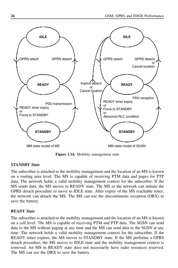
1.4.5 Mobility ManagementThe mobility management in the GPRS network is handled almost the same way as inthe existing GSM system. One or more cells form a routing area, which is a subset of onelocation area. Every routing area is served by one SGSN. The tracking of the location ofan MS depends on the mobility management state. When an MS is in a STANDBY state,the location of the MS is known on a routing area level. When the MS is in a READYstate, the location of the MS is known on a cell level. Figure 1.14 shows the differentmobility management states and transitions between them.
1.4.5.1 Mobility Management States
The GPRS has three various mobility management states. The IDLE state is used when thesubscriber (MS) is passive (not GPRS attached). The STANDBY state is used when thesubscriber has ended an active phase. An MS is in an active phase (READY state) whenit is transmitting or has just been transmitting. The change between the states happensupon activity or when a timer expires. A description of the various states is given below.
IDLE State
The subscriber is not reachable by the GPRS network. The MS is only capable of receivingPTM-M data. The network elements hold no valid context for the subscriber and thesubscriber is not attached to the mobility management. In order to change state, the MShas to perform a GPRS attach procedure.
26 GSM, GPRS and EDGE Performance
IDLE
GPRS attach GPRS detach
READY timer expiryorForce to STANDBY
PDU transmission
GPRS attach GPRS detachor
Cancel location
READY timer expiryorForce to STANDBYorAbnormal RLC condition
Implicit detachor
Cancel location
PDU reception
READY
STANDBY
IDLE
READY
STANDBY
MM state model of MS MM state model of SGSN
Figure 1.14. Mobility management state
STANDBY State
The subscriber is attached to the mobility management and the location of an MS is knownon a routing area level. The MS is capable of receiving PTM data and pages for PTPdata. The network holds a valid mobility management context for the subscriber. If theMS sends data, the MS moves to READY state. The MS or the network can initiate theGPRS detach procedure to move to IDLE state. After expiry of the MS reachable timer,the network can detach the MS. The MS can use the discontinuous reception (DRX) tosave the battery.
READY State
The subscriber is attached to the mobility management and the location of an MS is knownon a cell level. The MS is capable of receiving PTM and PTP data. The SGSN can senddata to the MS without paging at any time and the MS can send data to the SGSN at anytime. The network holds a valid mobility management context for the subscriber. If theREADY timer expires, the MS moves to STANDBY state. If the MS performs a GPRSdetach procedure, the MS moves to IDLE state and the mobility management context isremoved. An MS in READY state does not necessarily have radio resources reserved.The MS can use the DRX to save the battery.

GSM/EDGE Standards Evolution (up to Rel’4) 27
1.4.5.2 GPRS Attach and Detach
GPRS attach and GPRS detach are mobility management functions to establish and toterminate a connection to the GPRS network. The SGSN receives the requests and pro-cesses them. With the GPRS attach the mobile moves to READY state and the mobilitymanagement context is established, the MS is authenticated, the ciphering key is gener-ated, a ciphered link established and the MS is allocated a temporary logical link identity.The SGSN fetches the subscriber information from the HLR. After a GPRS attach, theSGSN tracks the location of the MS. The MS can send and receive SMS, but no otherdata. To transfer other data, it has to first activate a PDP context.
When the subscriber wants to terminate a connection to the GPRS network, the GPRSdetach is used. The GPRS detach moves the MS to IDLE state and the mobility manage-ment context is removed. The MS can also be detached from the GPRS implicitly whenthe mobile reachable timer expires. The GPRS detach is normally generated by the MS,but can also be generated by the network.
1.4.6 PDP Context Functions and Addresses
The packet data protocol (PDP) context functions are network level functions, which areused to bind an MS to various PDP addresses and afterwards used to unbind the MS fromthese addresses. The PDP context can also be modified. When an MS is attached to thenetwork, it has to activate all the addresses it wants to use for data traffic with the externalnetworks. Various PDP contexts have to be activated because these include address, QoSattributes, etc. After the subscriber has finished the use of activated addresses, thesehave to be deactivated. Also, change of address specific attributes have to be performedsometimes. The MS can use these functions when in STANDBY or READY state. TheGGSN can also use these functions, but the SGSN is responsible for performing thesefunctions. The MS can select a particular GGSN for access to certain services and alsoactivate a PDP context anonymously, without using any identification.
1.4.6.1 Dynamic and Static PDP Address
The subscriber can use various kinds of PDP addresses. A static PDP address is perma-nently assigned to an MS by the HPLMN. An HPLMN dynamic PDP address is assignedto an MS by the HPLMN when an MS performs a PDP context activation. A visitedpublic land mobile network (VPLMN) dynamic PDP address is assigned to an MS by theVPLMN when an MS performs a PDP context activation. It is indicated in the subscriptionif the MS can have a dynamic address or not.
1.4.6.2 PDP Context Activation
The PDP context activation can be done by the MS or by the network. The activate PDPcontext request is sent to the SGSN when a certain address requires activation. As anoption, the request can also be made by the GGSN, if packets are received for an addresswithout active context and the MS is GPRS attached. The request contains parameters forthe context, like the TLLI, the protocol type, the address type, QoS, requested GGSN, etc.
28 GSM, GPRS and EDGE Performance
1.4.6.3 PDP Context Modification
The PDP context can be modified by the SGSN with the modify PDP context. Onlythe parameters’ QoS negotiated and radio priority can be changed. The SGSN sends therequest to the MS, which either accepts the new QoS by sending a modify PDP contextaccept to the SGSN or does not accept it by sending a deactivate PDP context requestfor that context. In GPRS Phase 2 also, MS and GGSN can modify PDP context.
1.4.6.4 PDP Context Deactivation
The PDP context can be deactivated by the MS or by the network. Every address canbe deactivated separately, but when the GPRS detach is performed, the network willautomatically remove all the PDP contexts.
1.4.7 SecurityThe GPRS system uses GSM Phase 2–based security. These security functions includethe authentication of the subscriber, the user identity confidentiality and the cipheringof the data traffic between the MS and the SGSN. The authentication of the subscriberis done the same way by the SGSN in the GPRS system as by the MSC/VLR in thePhase 2 GSM network. The TLLI is used to keep the subscriber identity confidential. Thecorrespondence between the international mobile subscriber identity (IMSI) and the TLLIis only known by the MS and the SGSN. The ciphering function used between the MS andthe SGSN is not the same as that used in the GSM Phase 2, but an optimised one for thepacket-switched traffic. Security of the backbone is provided by using a private network,thus avoiding the possibility that an external hacker can address it. Each operator mustguarantee its physical security.
1.4.8 Location ManagementThe location management procedures are used to handle the changing of a cell and/ora routing area, and the periodic routing area updates. If an MS stays a long time atthe same place, the network has to receive an indication that the MS is still reachable.This is the reason why periodic routing area updates are made. All the MSs attachedto the GPRS will perform a periodic routing area update. Only the Class B mode ofoperation mobiles, which are engaged in a circuit-switched communication, cannot. TheMS performs a cell update when it changes cell within a routing area in READY mode.When the MS changes cell between the different routing areas, it performs a routingarea update. There are two types of routing area updates, the intra-SGSN routing areaupdate and the inter-SGSN routing area update. An SGSN can manage many routingareas and if the new routing area belongs to the management of a new SGSN, the inter-SGSN routing area update is used. If the new routing area belongs to the management ofthe same SGSN than the old one, the intra-SGSN routing area update is used. The oldSGSN forwards user packets to the new SGSN, until it receives a cancel location fromthe HLR.
1.4.9 GPRS Radio InterfaceThis section gives an overview of the GPRS Rel’97 radio interface.

GSM/EDGE Standards Evolution (up to Rel’4) 29
1.4.9.1 GPRS Packet Data Logical Channels
This section describes the logical channels of the GPRS radio interface. The reasonfor defining a new set of control channels for the GPRS packet data, which is partlyparallel to that of the circuit-switched control channels, is to be able to flexibly allocatemore signalling capacity for the packet data traffic without sacrificing the quality of thespeech traffic.
The packet data logical channels are mapped onto the physical channels that are ded-icated to packet data. The physical channel dedicated to packet data traffic is called apacket data channel (PDCH).
The packet data logical channels can be grouped into different categories as shown inFigure 1.15. These categories (packet common control channels, packet broadcast controlchannels, packet traffic channels and packet dedicated control channels) are introduced inmore detail in the following list [14].
Packet Common Control Channel (PCCCH)
PCCCH comprises logical channels for common control signalling used for packet data:
• Packet random access channel (PRACH)—uplink only. PRACH is used by the MSto initiate uplink transfer to send data or signalling information.
• Packet paging channel (PPCH)—downlink only. PPCH is used to page an MS priorto downlink packet transfer.
• Packet access grant channel (PAGCH)—downlink only. PAGCH is used in the packettransfer establishment phase to send resource assignment to an MS prior to packettransfer.
• Packet notification channel (PNCH)—downlink only. PNCH is used to send a PTM-M (point to multipoint—multicast) notification to a group of MSs prior to a PTM-Mpacket transfer. (Note that the PTM-M service is not specified in GPRS Rel’97.)
Packet Broadcast Control Channel (PBCCH)—Downlink only
PBCCH broadcasts packet data specific system information. If PBCCH is not allocated,the packet data specific system information is broadcast on BCCH.
PDCH
PBCCH PCCCH PDTCH PACCH
PRACH PPCH PAGCH PNCH
Downlink only
Uplink only Downlink only Downlink only
Logical channels
Physical channel
Downlink only
Figure 1.15. GPRS logical channels

30 GSM, GPRS and EDGE Performance
Packet Traffic Channels
• Packet data traffic channel (PDTCH). PDTCH is a channel allocated for data transfer.It is temporarily dedicated to one MS. In the multislot operation, one MS may usemultiple PDTCHs in parallel for individual packet transfer.
All packet data traffic channels are uni-directional, either uplink (PDTCH/U), fora mobile-originated packet transfer, or downlink (PDTCH/D), for a mobile terminatedpacket transfer.
Packet Dedicated Control Channels
• Packet associated control channel (PACCH). PACCH conveys signalling informationrelated to a given MS. The signalling information includes, e.g. acknowledgementsand power control information. PACCH also carries resource assignment and reas-signment messages comprising the assignment of a capacity for PDTCH(s) and forfurther occurrences of PACCH. The PACCH shares resources with PDTCHs, whichare currently assigned to one MS. Additionally, an MS that is currently involved inpacket transfer can be paged for circuit-switched services on PACCH.
• Packet timing advance control channel, uplink (PTCCH/U). PTCCH/U is used totransmit random access bursts to allow estimation of the timing advance for oneMS in packet transfer mode.
• Packet timing advance control channel, downlink (PTCCH/D). PTCCH/D is used totransmit timing advance information updates to several MSs. One PTCCH/D is pairedwith several PTCCH/Us.
1.4.9.2 Mapping of Packet Data Logical Channels into Physical Channels
Different packet data logical channels can occur on the same physical channel (i.e. PDCH).The sharing of the physical channel is based on blocks of four consecutive bursts, exceptfor PTCCH. The mapping in frequency of PDCH onto the physical channel is definedin [5].
On PRACH and PTCCH/U, access bursts are used. On all other packet data logicalchannels, radio blocks comprising four normal bursts are used. The only exceptions aresome messages on uplink PACCH that comprise four consecutive access bursts (to increaserobustness). The following list shows some more details about how the packet data logicalchannels are mapped onto physical channels.
Packet Common Control Channel (PCCCH)
At a given time, the logical channels of the PCCCH are mapped on different physicalresources than the logical channels of the CCCH. The PCCCH does not have to beallocated permanently in the cell. Whenever the PCCCH is not allocated, the CCCH shallbe used to initiate a packet transfer. The PCCCH, when it exists, is mapped on one orseveral physical channels according to a 52-multiframe. In that case, the PCCCH, PBCCH

GSM/EDGE Standards Evolution (up to Rel’4) 31
and PDTCH share the same physical channels (PDCHs). The existence and location ofthe PCCCH shall be broadcast on the cell.
• Packet random access channel (PRACH). The PRACH is mapped on one or severalphysical channels. The physical channels on which the PRACH is mapped are derivedby the MS from information broadcast on the PBCCH or BCCH.
PRACH is determined by the uplink state flag (USF) being marked as free, whichis broadcast continuously on the corresponding downlink. Additionally, a pre-definedfixed part of the multiframe structure for PDCH can be used as PRACH only and theinformation about the mapping on the physical channel is broadcast on PBCCH. Dur-ing those time periods, an MS does not have to monitor the USF that is simultaneouslybroadcast on the downlink.
• Packet paging channel (PPCH). The PPCH is mapped on one or several physicalchannels. The exact mapping on each physical channel follows a pre-defined rule, asit is done for the paging channel (PCH).
The physical channel on which the PPCH is mapped, as well as the rule that isfollowed on the physical channels, are derived by the MS from information broadcaston the PBCCH.
• Packet access grant channel (PAGCH). The PAGCH is mapped on one or severalphysical channels. The exact mapping on each physical channel follows a pre-definedrule.
The physical channels on which the PAGCH is mapped, as well as the rule that isfollowed on the physical channels, are derived by the MS from information broadcaston the PBCCH.
• Packet notification channel (PNCH). The PNCH is mapped on one or several blockson PCCCH. The exact mapping follows a pre-defined rule. The mapping is derivedby the MS from information broadcast on the PBCCH.
Packet Broadcast Control Channel (PBCCH)
The PBCCH shall be mapped on one or several physical channels. The exact mappingon each physical channel follows a pre-defined rule, as it is done for the BCCH.
The existence of the PCCCH and, consequently, the existence of the PBCCH, is indi-cated on the BCCH.
Packet Timing Advance Control Channel (PTCCH)
Two defined frames of multiframe are used to carry PTCCH. The exact mapping ofPTCCH/U sub-channels and PTCCH/D are defined in [5].
On PTCCH/U, access bursts are used. On PTCCH/D, four normal bursts comprisinga radio block are used.
Packet Traffic Channels
• Packet data traffic channel (PDTCH). One PDTCH is mapped on to one physicalchannel. Up to eight PDTCHs, with different timeslots but with the same frequencyparameters, may be allocated to one MS at the same time.

32 GSM, GPRS and EDGE Performance
• Packet associated control channel (PACCH). PACCH is dynamically allocated on ablock basis on the same physical channel that is carrying PDTCHs. However, oneblock PACCH allocation is used on the physical channel that is carrying only PCCCHwhen the MS is polled to acknowledge the initial assignment message.
PACCH is of a bi-directional nature, i.e. it can dynamically be allocated both onthe uplink and on the downlink, regardless of whether the corresponding PDTCHassignment is for uplink or downlink.
Different packet data logical channels can be multiplexed in one direction (either on thedownlink or uplink) on the same physical channel (i.e. PDCH). The reader is advisedto see details in [5]. The type of message that is indicated in the radio block headerallows differentiation between the logical channels. Additionally, the MS identity allowsdifferentiation between PDTCHs and PACCHs assigned to different MSs.
1.4.9.3 Radio Interface (Um)
Radio Resource Management Principles
A cell supporting GPRS may allocate resources on one or several physical channels inorder to support the GPRS traffic [14]. Those physical channels (i.e. PDCHs), sharedby the GPRS MSs, are taken from the common pool of physical channels available inthe cell. The allocation of physical channels to circuit-switched services and GPRS canvary dynamically. Common control signalling required by GPRS in the initial phase ofthe packet transfer is conveyed on PCCCH (when allocated), or on CCCH. This allowscapacity to be allocated specifically to GPRS in the cell only when a packet is to betransferred.
At least one PDCH, acting as a primary PDCH, accommodates packet common con-trol channels that carry all the necessary control signalling for initiating packet transfer(i.e. PCCCH), whenever that signalling is not carried by the existing CCCH, as well asuser data and dedicated signalling (i.e. PDTCH and PACCH). Other PDCHs, acting assecondary PDCHs, are used for user data transfer and for dedicated signalling.
The GPRS does not require permanently allocated PDCHs. The allocation of capacityfor GPRS can be based on the needs for actual packet transfers (‘capacity on demand’principle). The operator can as well decide to dedicate, permanently or temporarily, somephysical resources (i.e. PDCHs) for GPRS traffic.
When the PDCHs are congested owing to the GPRS traffic load and more resourcesare available in the cell, the network can allocate more physical channels as PDCHs.However, the existence of PDCH(s) does not imply the existence of PCCCH. When noPCCCH is allocated in a cell, all GPRS attached MSs camp on the CCCH.
In response to a packet channel request sent on CCCH from the MS that wants totransmit GPRS packets, the network can assign resources on PDCH(s) for the uplinktransfer. After the transfer, the MS returns to CCCH.
When PCCCH is allocated in a cell, all GPRS attached MSs camp on it. PCCCHcan be allocated either as the result of the increased demand for packet data transfers orwhenever there are enough available physical channels in a cell (to increase the QoS). Theinformation about PCCCH is broadcast on BCCH. When the PCCCH capacity is inade-quate, it is possible to allocate additional PCCCH resources on one or several PDCHs. Ifthe network releases the last PCCCH, the MS performs cell re-selection.

GSM/EDGE Standards Evolution (up to Rel’4) 33
The number of allocated PDCHs in a cell can be increased or decreased accordingto demand.
Multiframe Structure for PDCH
The mapping in time of the logical channels is defined by a multiframe structure. Themultiframe structure for PDCH consists of 52 TDMA frames, divided into 12 blocks (of4 frames), 2 idle frames and 2 frames used for the PTCCH according to Figure 1.16.
The mapping of logical channels onto the radio blocks is defined in this section bymeans of the ordered list of blocks (B0, B6, B3, B9, B1, B7, B4, B10, B2, B8, B5, B11).
The PDCH that contains PCCCH (if any) is indicated on BCCH. That PDCH is theonly one that contains PBCCH blocks. On the downlink of this PDCH, the first block(B0) in the ordered list of blocks is used as PBCCH. If required, up to three more blockson the same PDCH can be used as additional PBCCH. Any additional PDCH containingPCCCH is indicated on PBCCH.
On any PDCH with PCCCH (with or without PBCCH), up to the next 12 blocks in theordered list of blocks are used for PAGCH, PNCH, PDTCH or PACCH in the downlink.The remaining blocks in the ordered list are used for PPCH, PAGCH, PNCH, PDTCH orPACCH in the downlink. In all cases, the actual usage of the blocks is indicated by themessage type. On an uplink PDCH that contains PCCCH, all blocks in the multiframecan be used as PRACH, PDTCH or PACCH. Optionally, the first blocks in the orderedlist of blocks can only be used as PRACH. The MS may choose to either ignore the USF(consider it as FREE) or use the USF to determine the PRACH in the same way as forthe other blocks.
The mapping of channels on multiframes is controlled by several parameters broadcaston PBCCH. On a PDCH that does not contain PCCCH, all blocks can be used as PDTCHor PACCH. The actual usage is indicated by the message type. Two frames are usedfor PTCCH (see [5]) and the two idle frames as well as the PTCCH frames can beused by the MS for signal measurements and base station identification code (BSIC)identification.
An MS attached to GPRS shall not be required to monitor BCCH if a PBCCH exists.All system information relevant for GPRS and some information relevant for circuit-switched services (e.g. the access classes) shall in this case be broadcast on PBCCH. Inorder to facilitate the MS operation, the network is required to transmit certain types ofpacket system information (PSI) messages in specific multiframes and specific PBCCHblocks within the multiframes. The exact scheduling is defined in [5]. If no PCCCH isallocated, the MS camps on the CCCH and receives all system information on BCCH. Inthis case, any necessary GPRS-specific system information has to be broadcast on BCCH.
52 TDMA frames
B0 B1 B2
X = Idle frameT = frame used for PTCCH
B0–B11 = radio blocks
B3T X T XB4 B5 B6 B7 B8 B9 B10 B11
Figure 1.16. Multiframe structure for PDCH [14]

34 GSM, GPRS and EDGE Performance
Radio Resource Operating Modes
Radio resource (RR) management procedures are characterised by two different RR oper-ating modes [14], packet idle mode and packet transfer mode.
In packet idle mode, no temporary block flow (TBF) exists. Upper layers can requirethe transfer of a LLC PDU, which, implicitly, may trigger the establishment of TBF andtransition to packet transfer mode.
In packet idle mode, the MS listens to the PBCCH and to the paging sub-channel forthe paging group the MS belongs to. If PCCCH is not present in the cell, the MS listensto the BCCH and to the relevant paging sub-channels.
In packet transfer mode, the mobile station is allocated radio resource, providing aTBF on one or more physical channels. Continuous transfer of one or more LLC PDUsis possible. Concurrent TBFs may be established in opposite directions. Transfer of LLCPDUs in RLC acknowledged or RLC unacknowledged mode is provided.
When selecting a new cell, the MS leaves the packet transfer mode, enters the packetidle mode where it switches to the new cell, reads the system information and may thenresume to packet transfer mode in the new cell.
The mobility management states are defined in [15]. Table 1.3 provides the correspon-dence between radio resource states and mobility management states.
Each state is protected by a timer. The timers run in the MS and the network. Packettransfer mode is guarded by RLC protocol timers.
The GPRS RR procedures and RR operating modes are defined in detail in [16].
Physical Link Layer
Different radio block structures are defined for the data transfer and for the control messagetransfer. The radio block consists of MAC header, RLC data block or RLC/MAC controlblock (Figure 1.17). It is always carried by four normal bursts. For detailed definition ofradio block structure, see [17].
The MAC header (8 bits) contains control fields, which are different for uplink anddownlink directions. The RLC header is of variable length and contains control fields,which are as well different for uplink and downlink directions. The RLC data field containsoctets from one or more LLC packet data units (PDUs). The block check sequence (BCS)is used for error detection. The RLC/MAC control message field contains one RLC/MACcontrol message.
Channel Coding
Four coding schemes, CS-1 to CS-4, are defined for the packet data traffic channels. Forall packet control channels (PCCHs) other than packet random access channel (PRACH)
Table 1.3. Correspondence between RR operating modes and MM states [14]
Radio resource BSS Packet transfermode
Measurement reportreception
No state No state
Radio resourceMS
Packet transfermode
Packet idle mode Packet idle mode
Mobilitymanagement NSSand MS
Ready Standby

GSM/EDGE Standards Evolution (up to Rel’4) 35
Radio block
MAC header RLC header RLC data
RLC data block (Part of physical link)
Radio block
MAC header RLC/MAC control message
RLC/MAC control block (Part of physical link)
Figure 1.17. Radio block structures [14]
and packet timing advance control channel on uplink (PTCCH/U), coding scheme CS-1 isalways used. For access bursts on PRACH, two coding schemes are specified. All codingschemes are mandatory for the MS. Only CS-1 is mandatory for the network.
Channel Coding for PDTCH
Four different coding schemes, CS-1 to CS-4, are defined for the radio blocks carryingRLC data blocks. The block structures of the coding schemes are shown in Figures 1.18and 1.19.
The first step of the coding procedure is to add a BCS for error detection. For the CS-1to CS-3, the second step consists of pre-coding USF (except for CS-1), adding four tailbits (TBs) and a half-rate convolutional coding for error correction that is punctured togive the desired coding rate. For the CS-4, there is no coding for error correction. Thedetails of the codes are shown in Table 1.4, including the length of each field, the numberof coded bits (after adding tail bits and convolutional coding), the number of puncturedbits and the data rate (including the RLC header and RLC information).
Radio block
Rate 1/2 convolutional coding
456 bits
Puncturing
USF BCS
Figure 1.18. Radio block structure for CS-1 to CS-3
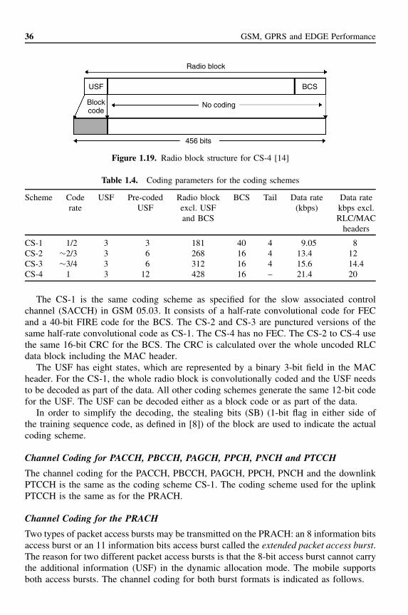
36 GSM, GPRS and EDGE Performance
Radio block
456 bits
No coding
USF
Blockcode
BCS
Figure 1.19. Radio block structure for CS-4 [14]
Table 1.4. Coding parameters for the coding schemes
Scheme Coderate
USF Pre-codedUSF
Radio blockexcl. USFand BCS
BCS Tail Data rate(kbps)
Data ratekbps excl.RLC/MAC
headers
CS-1 1/2 3 3 181 40 4 9.05 8CS-2 ∼2/3 3 6 268 16 4 13.4 12CS-3 ∼3/4 3 6 312 16 4 15.6 14.4CS-4 1 3 12 428 16 – 21.4 20
The CS-1 is the same coding scheme as specified for the slow associated controlchannel (SACCH) in GSM 05.03. It consists of a half-rate convolutional code for FECand a 40-bit FIRE code for the BCS. The CS-2 and CS-3 are punctured versions of thesame half-rate convolutional code as CS-1. The CS-4 has no FEC. The CS-2 to CS-4 usethe same 16-bit CRC for the BCS. The CRC is calculated over the whole uncoded RLCdata block including the MAC header.
The USF has eight states, which are represented by a binary 3-bit field in the MACheader. For the CS-1, the whole radio block is convolutionally coded and the USF needsto be decoded as part of the data. All other coding schemes generate the same 12-bit codefor the USF. The USF can be decoded either as a block code or as part of the data.
In order to simplify the decoding, the stealing bits (SB) (1-bit flag in either side ofthe training sequence code, as defined in [8]) of the block are used to indicate the actualcoding scheme.
Channel Coding for PACCH, PBCCH, PAGCH, PPCH, PNCH and PTCCH
The channel coding for the PACCH, PBCCH, PAGCH, PPCH, PNCH and the downlinkPTCCH is the same as the coding scheme CS-1. The coding scheme used for the uplinkPTCCH is the same as for the PRACH.
Channel Coding for the PRACH
Two types of packet access bursts may be transmitted on the PRACH: an 8 information bitsaccess burst or an 11 information bits access burst called the extended packet access burst.The reason for two different packet access bursts is that the 8-bit access burst cannot carrythe additional information (USF) in the dynamic allocation mode. The mobile supportsboth access bursts. The channel coding for both burst formats is indicated as follows.

GSM/EDGE Standards Evolution (up to Rel’4) 37
• Coding of the 8 data bit packet access burst. The channel coding used for the burstcarrying the 8 data bit packet access uplink message is identical to the coding of theaccess burst as defined for the random access channel in [8].
• Coding of the 11 data bit packet access burst. The channel coding for the 11-bit accessburst is the punctured version of the same coding as used for the 8-bit access burst.
Cell Re-selection
Initial PLMN selection and cell selection are done when the mobile station power isswitched on. In GPRS packet, idle cell re-selection is performed autonomously by the MS.In GPRS packet transfer mode, the cell re-selection mechanism depends on the networkoperational mode. There are three network control modes: NC0, NC1 and NC2. In NC0,the MS performs the cell re-selection autonomously as in idle mode. In NC1, the MSalso performs the cell re-selection autonomously but, in addition, it sends measurementreports to the network periodically. The measurement reports are analogous to the onessent every 0.48 s in voice and CS data connections. In NC2, the MS sends periodicalmeasurement reports and, additionally, the network sends cell re-selection commands tothe MS, so the network has control of the cell re-selection process.
When the MS is attached to the circuit-switched core network (to MSC) and at thesame time it is in packet transfer mode, the cell is determined by the network accordingto the handover procedures (handovers have precedence over GPRS cell re-selection).
In GPRS, two additional cell re-selection criteria, C31 and C32, are provided as a com-plement to the other GSM cell re-selection criteria. Cell re-selection criteria are specifiedin [4].
Also, a network controlled cell re-selection can be used in GPRS. The network canorder mobile stations to send measurement reports to the network and to suspend itsnormal cell re-selection, and instead to accept decisions from the network. This appliesto both packet idle mode and packet transfer mode. The MS measures the received RFsignal strength on the BCCH frequencies of the serving cell and the neighbour cellsas indicated in the BA-GPRS list and calculates the received level average (RLA) foreach frequency, as defined in [4]. In addition, the MS verifies the BSIC of the cells.Only channels with the same BSIC as broadcast together with BA-GPRS on PBCCH areconsidered for re-selection.
The PBCCH broadcasts GPRS-specific cell re-selection parameters for serving andneighbour cells, including the BA-GPRS list. A BA-GPRS identifies the neighbour cells,including BSIC that need to be considered for the GPRS cell re-selection.
Timing Advance
The timing advance procedure is used to derive the correct value for timing advancethat the MS has to use for the uplink transmission of radio blocks. The timing advanceprocedure comprises two parts:
• initial timing advance estimation
• continuous timing advance update.
The initial timing advance estimation is based on the single access burst carrying thepacket channel request. The packet uplink assignment or packet downlink assignment

38 GSM, GPRS and EDGE Performance
then carries the estimated timing advance value to the MS. The MS uses this value forthe uplink transmissions until the continuous timing advance update provides a new value(a few special cases for the initial timing advance are explained in [14]).
In the packet transfer mode, the MS uses the continuous timing advance update proce-dure. The continuous timing advance update procedure is carried on the PTCCH allocatedto the MS. For the uplink packet transfer, within the packet uplink assignment, the MSis assigned the timing advance index (TAI) and the PTCCH. For the downlink packettransfer, within the packet downlink assignment, the MS is assigned the TAI and thePTCCH. The TAI specifies the PTCCH sub-channel used by the MS. On the uplink, theMS sends the assigned PTCCH access burst, which is used by the network to derive thetiming advance.
The network analyses the received access burst and determines new timing advancevalues for all MSs performing the continuous timing advance update procedure on thatPDCH. The new timing advance values are sent via a downlink signalling message (TAmessage) on PTCCH/D. The network can send timing advance information also in packettiming advance/power control and packet uplink Ack/Nack messages on PACCH. Themapping of the uplink access bursts and downlink TA messages on groups of eight52-multiframes is shown in [14].
The BTS updates the timing advance values in the next TA message following theaccess burst.
Power Control Procedure
Power control is used in order to improve the spectrum efficiency and to reduce thepower consumption in the MS. For the uplink, the MS follows a flexible power controlalgorithm, which the network can optimise through a set of parameters. It can be usedfor both open-loop and closed-loop power control. For the downlink, the power control isperformed in the BTS. There is no need to specify the actual algorithms, but informationabout the downlink performance is needed. Therefore, the MSs transfer channel qualityreports to the BTS. For the detailed specification of the power control see [4].
The MS shall calculate the RF output power value, PCH, to be used on each individualuplink PDCH assigned to the MS [14]:
PCH = min((�0 − �CH − α∗(C + 48), PMAX)
where
�CH = an MS and channel-specific power control parameter. It is sent to the MSin any resource assigning message. The network can, at any time during apacket transfer, send new �CH values to the MS on the downlink PACCH
�0 = frequency band–dependent constantα ∈ [0, 1] = a system parameter. Its default value is broadcast on the PBCCH. MS and
channel-specific values can be sent to the MS together with �CH
C = received signal level at the MS (see [14] for the derivation of this value)P MAX = maximum allowed output power in the cell
All power values are expressed in dBm.

GSM/EDGE Standards Evolution (up to Rel’4) 39
PCH is not used to determine the output power when accessing the cell on PRACH orRACH, in which case PMAX is used.
The BTS uses constant power on those PDCH radio blocks that contain PBCCH or thatmay contain PPCH. This power may be lower than the output power used on BCCH. Thedifference is broadcast on PBCCH. On the other PDCH radio blocks, downlink powercontrol can be used. Thus, a procedure can be implemented in the network to controlthe power of the downlink transmission on the basis of the channel quality reports. Thenetwork has to ensure that the output power is sufficient for the MS for which the RLCblock is intended as well as the MS(s) for which the USF is intended, and that foreach MS in packet transfer mode, at least one downlink RLC block per multiframe istransmitted with an output power that is sufficient for that MS, on a block monitored bythat MS.
The MS has to periodically monitor the downlink Rx signal level and quality from itsserving cell.
In order to derive the value of C, the MS periodically measures the received signalstrength. In the packet idle mode, the MS measures the signal strength of the PCCCHor, if PCCCH does not exist, the BCCH. In the packet transfer mode, the MS measuresthe signal strength on BCCH. The same measurements as for cell re-selection are used.Alternatively, if indicated by a broadcast parameter, the MS measures the signal strengthon one of the PDCHs where the MS receives PACCH. This method is suitable in the casein which BCCH is in another frequency band than the one used by PDCHs. It requiresthat constant output power is used on all downlink PDCH blocks.
MS Measurements
The MS measures the signal strength of each radio block monitored by the MS. TheC value is achieved by filtering the signal strength with a running average filter. Thefiltering is usually continuous between the packet modes. The different filter parametersfor the packet modes are broadcast on PBCCH or, if PBCCH does not exist, on BCCH.The variance of the received signal level within each block is also calculated. The filteredvalue SIGN VAR is included in the channel quality report.
The channel quality is measured as the interference signal level during the idle framesof the multiframe, when the serving cell is not transmitting. In the packet transfer mode,the MS measures the interference signal strength of all eight channels (slots) on the samecarrier as the assigned PDCHs. In the packet idle mode, the MS measures the interferencesignal strength on certain channels that are indicated on the PBCCH or, if PBCCH doesnot exist, on BCCH. Some of the idle frames and PTCCH frames are used for the channelquality measurements, while the others are required for BSIC identification and the timingadvance procedure (see [4] for details).
The MS may not be capable of measuring all eight channels when allocated someconfigurations of channels. The MS has to measure as many channels as its allocationallows, taking into account its multislot capability. The interference, �CH, is derived byfiltering the measured interference in a running average filter.
In packet transfer mode, the MS transfers the eight �CH values and the RXQUAL,SIGN VAR and C values to the network in the channel quality report included in thePACKET DOWNLINK ACK/NACK message.
40 GSM, GPRS and EDGE Performance
The BSS has to monitor the uplink Rx signal level and quality on each uplink PDCH,active as well as inactive. The BSS also has to measure the Rx signal level and the qualityof a specific MS packet transfer.
Scheduling the MS activities during the PTCCH and idle frames. The MS uses the PTCCHand idle frames of the PDCH multiframe for the following tasks:
• Neighbour cell–level measurement and BSIC identification for cell re-selection
• Continuous timing advance procedures
• Interference measurements.
The scheduling of these tasks is not specified in detail. During the frames when theMS receives TA messages, it can also make interference measurements. Additionally,during the frames when the MS transmits access bursts, it may also be possible to makemeasurements on some channels.
The MS tries to schedule the BSIC identification as efficiently as possible, using theremaining PTCCH frames and the idle frames and also considering the requirements forinterference measurements.
Discontinuous reception (DRX). The MS has to support discontinuous reception (DRX;sleep mode) in packet idle mode. The DRX is independent from mobility management(MM) states, ready and standby. The negotiation of the DRX parameters is per MS. TheDRX parameters and the overview of DRX operation are explained in [14].
Medium Access Control and Radio Link Control Layer
The medium access control and radio link control layer operates above the physical linklayer in the protocol architecture. The MAC function defines the procedures that enablemultiple MSs to share a common transmission medium, which may consist of severalphysical channels. The RLC function defines the procedures for a selective re-transmissionof unsuccessfully delivered RLC data blocks. MAC/RLC is a complex protocol, and fordetails the reader is referred to [17]. This section gives only an introduction of the mainfunctions of the RLC/MAC layer.
The basic principle of data transfer is illustrated in Figure 1.20. The network protocoldata units (N-PDU), which correspond to full IP packets, are compressed and seg-mented into the sub-network protocol data units (SN-PDU) by the sub-network-dependentconvergence protocol (SNDCP). IP-packet compression is optional. The SN-PDUs areencapsulated into one or several LLC frames. The size of the data part of the LLC framesis a parameter between 140 and 1520 bytes. LLC frames are segmented into RLC datablocks. At the RLC/MAC layer, a selective automatic repeat request (ARQ) protocol(including block numbering) between the MS and the network provides re-transmissionof erroneous RLC data blocks. When a complete LLC frame is successfully transferredacross the RLC layer, it is forwarded to the LLC layer.
There are two important concepts that constitute the core of RLC/MAC operation:temporary block flow and temporary flow identifier.
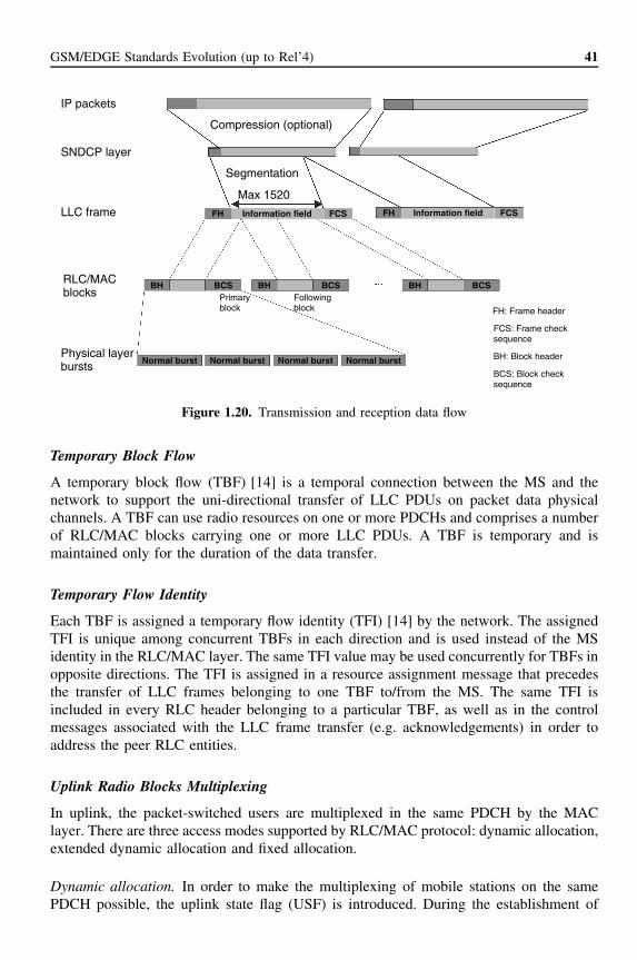
GSM/EDGE Standards Evolution (up to Rel’4) 41
IP packets
SNDCP layer
Compression (optional)
Segmentation
Max 1520
LLC frame
RLC/MACblocks
FH: Frame header
Normal burst
FCS: Frame checksequence
BCS: Block checksequence
BH: Block headerPhysical layerbursts
BH
Normal burst Normal burst Normal burst
BCSPrimaryblock
Followingblock
BH BCS
FH FCSInformation field
BH BCS
FH FCSInformation field
Figure 1.20. Transmission and reception data flow
Temporary Block Flow
A temporary block flow (TBF) [14] is a temporal connection between the MS and thenetwork to support the uni-directional transfer of LLC PDUs on packet data physicalchannels. A TBF can use radio resources on one or more PDCHs and comprises a numberof RLC/MAC blocks carrying one or more LLC PDUs. A TBF is temporary and ismaintained only for the duration of the data transfer.
Temporary Flow Identity
Each TBF is assigned a temporary flow identity (TFI) [14] by the network. The assignedTFI is unique among concurrent TBFs in each direction and is used instead of the MSidentity in the RLC/MAC layer. The same TFI value may be used concurrently for TBFs inopposite directions. The TFI is assigned in a resource assignment message that precedesthe transfer of LLC frames belonging to one TBF to/from the MS. The same TFI isincluded in every RLC header belonging to a particular TBF, as well as in the controlmessages associated with the LLC frame transfer (e.g. acknowledgements) in order toaddress the peer RLC entities.
Uplink Radio Blocks Multiplexing
In uplink, the packet-switched users are multiplexed in the same PDCH by the MAClayer. There are three access modes supported by RLC/MAC protocol: dynamic allocation,extended dynamic allocation and fixed allocation.
Dynamic allocation. In order to make the multiplexing of mobile stations on the samePDCH possible, the uplink state flag (USF) is introduced. During the establishment of

42 GSM, GPRS and EDGE Performance
the uplink TBF, a USF is assigned to each mobile, which will be used by the network toindicate which terminal is allowed to transmit in the following uplink radio block.
With this method, each downlink block has to be decoded by all the MSs assigned tothe PDCH in order to obtain the USF and the TFI, identifying the owner of the data orcontrol information. In addition, even if no downlink information is available, a dummyradio block must be sent just to transmit the USF when required.
The USF is a 3-bit flag, so each PDCH can manage up to eight MSs, except on thePCCH, where the value ‘111’ (USF = Free) indicates that the corresponding uplink radioblock is reserved for the packet random access channel (PRACH) [14]. There are only16 TA indexes for the continuous timing advance procedure to keep the MS synchro-nised with the TDMA frame at the BTS. If the maximum number of TBF multiplexedin UL is 7, the maximum number of TBF in DL is limited to 9 in the extreme casethat the 16 TBF (7 in UL and 9 in DL) multiplexed on the same PDCH belongs todifferent MSs.
A special channel coding is used for the USF added to the different coding schemesthat makes it quite reliable (even more than CS-1) and prevents uplink radio block losses.For multislot classes, the mobile must decode the USF in all PDCHs separately.
Whenever the MS detects an assigned USF value on an assigned PDCH, the MSshall transmit either a single RLC/MAC block or a sequence of four RLC/MAC blockson the same PDCH. The number of RLC/MAC blocks to transmit is controlled by theUSF GRANULARITY parameter characterising the uplink TBF [14].
The fact that the MS has to receive a USF on each timeslot (TSL) introduces limitationson the maximum number of TSLs supported in the UL direction for certain MS classes.In most practical cases, with the simplest (E)GPRS radio implementation, the maximumnumber of TSLs in UL is limited to two. This can be seen in Figure 1.21 with a 3 + 2MS allocation. Note that this limitation is very dependent on MS class.
Extended dynamic allocation. This procedure allows a higher number of TSLs in UL andeliminates the need of receiving USF on each TSL (which may create too many dummyblocks in DL). In this case, when a USF is received in a particular TSL, the MS is allowedto transmit on the same TSL and all the subsequent TSLs. Let us consider the allocationin Figure 1.22 where a 2 + 3 MS allocation is considered. When a USF is received onTSL 1, the MS will transmit on TSL 1 and 2. If simple dynamic allocation would beused, the MS would transmit only on TSL 1.
DL 0R
1R
2R
3 4 5 6 7
0 1T
2T
3 5
tb ra ra
6 7UL
tb: guard time between receiving and transmittingra: BCCH frequencies measurementsR: MS receivingT: MS transmitting
Figure 1.21. Dynamic UL allocation example

GSM/EDGE Standards Evolution (up to Rel’4) 43
DL 0R
1R
2 3 4 5 6 7
0T
1T
2T
3 5
tb ra ra
6 7UL
tb: guard time between receiving and transmittingra: BCCH frequencies measurementsR: MS receivingT: MS transmitting
Figure 1.22. Extended dynamic UL allocation example
Fixed allocation. Using this procedure, the network communicates with the MS andUL transmission turn pattern by using a specific control message. In this case, USF isnot utilised and, therefore, DL communication is point-to-point. This latter characteristicmakes it more suitable for link optimisation techniques like DL power control and smartantennas. Once an MS has requested a resource assignment for the uplink, the networkresponds with a bitmap (ALLOCATION BITMAP), indicating timeslots and radio blockswhere the MS is allowed to transmit after a frame number contained in the parameterTBF starting time.
Time is slotted in allocation periods with a configurable duration that will be the basictime unit to assign resources for an uplink TBF. If more than one allocation is neededfor the MS initial request, the network will send new bitmaps in packet ACK/NACKmessages at the end of the current allocation period.
Modes for RLC/MAC Operation
In addition, there are two distinctive modes of operation of RLC/MAC layer:
• unacknowledged operation
• acknowledged operation.
Acknowledged mode for RLC/MAC operation. The transfer of RLC data blocks in theacknowledged RLC/MAC mode is controlled by a selective ARQ mechanism coupledwith the numbering of the RLC data blocks within one temporary block flow. The sendingside (the MS or the network) transmits blocks within a window and the receiving sidesends packet uplink Ack/Nack or packet downlink Ack/Nack message when needed. Everysuch message acknowledges all correctly received RLC data blocks up to an indicatedblock sequence number (BSN). Additionally, the bitmap is used to selectively requesterroneously received RLC data blocks for re-transmission.
Unacknowledged mode for RLC/MAC operation. The transfer of RLC data blocks in theunacknowledged RLC/MAC mode is controlled by the numbering of the RLC data blockswithin one TBF and does not include any re-transmissions. The receiving side extractsuser data from the received RLC data blocks and attempts to preserve the user informationlength by replacing missing RLC data blocks by dummy information bits.

44 GSM, GPRS and EDGE Performance
Mobile-originated Packet Transfer
Uplink access. An MS initiates a packet transfer by making a packet channel request onPRACH or RACH, depending on the availability of PCCHs in the network. The networkresponds on PAGCH (if PCCHs are supported by the network) or access grant channel(AGCH), respectively. It is possible to use one- or two-phase packet access methods (seeFigure 1.23).
In the one-phase access, the network will respond to the packet channel request bysending a packet uplink assignment message and reserving the resources on PDCH(s)for uplink transfer of a number of radio blocks. The reservation is done according to therequested resources indicated in the packet channel request. On RACH, there are only twocause values available for denoting GPRS, which can be used to request limited resourcesor two-phase access. On PRACH, the packet channel request may contain more adequateinformation about the requested resources, and, consequently, uplink resources on one ormore PDCHs can be assigned by using the packet uplink assignment message.
In the two-phase access, the packet channel request is responded to with the packetuplink assignment, which reserves the uplink resources for transmitting the packet resourcerequest. A two-phase access can be initiated by the network or an MS. The network canorder the MS to send a packet resource request message by setting a parameter in packetuplink assignment message. The MS can require two-phase access in the packet channelrequest message. In this case, the network may order the MS to send a packet resourcerequest or continue with a one-phase access procedure.
The packet resource request message carries the complete description of the requestedresources for the uplink transfer. The MS can indicate the preferred medium access methodto be used during the TBF. The network responds with the packet uplink assignment,reserving resources for the uplink transfer and defining the actual parameters for datatransfer (e.g. medium access mode). If there is no response to the packet channel requestwithin the pre-defined time period, the MS makes a retry after a random time.
Optional
MS Network
Packet channel request
PRACH or RACH
Packet uplink assignment
PAGCH or AGCH
Packet resource request
PACCH
Packet uplink assignment
PACCH
Figure 1.23. Access and allocation for the one or two-phase packet access, uplink packet transfer

GSM/EDGE Standards Evolution (up to Rel’4) 45
On PRACH, a two-step approach is used and includes a long-term and a short-term esti-mation of the persistence [14]. The optimal persistence of the mobile stations is calculatedat the network side.
The actual persistence values depend on
• the priority of the packet to be transmitted;
• the amount of traffic within higher priority classes;
• the amount of traffic within its own priority class.
Occasionally, more packet channel requests can be received than can be served. To handlethis, a packet queuing notification is transmitted to the sender of the packet channelrequest. The notification includes information that the packet channel request message iscorrectly received and that the packet uplink assignment may be transmitted later. If thetiming advance information becomes inaccurate for an MS, the network can send packetpolling request to trigger the MS to send four random access bursts. This can be used toestimate the new timing advance before issuing the packet uplink assignment [14].
In case of dynamic or extended dynamic allocation, the packet uplink assignment mes-sage includes the list of PDCHs and the corresponding USF value per PDCH. A uniqueTFI is allocated and is thereafter included in each RLC data and control block relatedto that temporary block flow. The MS monitors the USFs on the allocated PDCHs andtransmits radio blocks when the USF value indicates to do so. In case of fixed allocation,the packet uplink assignment message is used to communicate a detailed fixed uplinkresource allocation to the MS. The fixed allocation consists of a start frame, slot assign-ment and block assignment bitmap representing the assigned blocks per timeslot [14].The MS will wait until the start frame and then transmit radio blocks on those blocksindicated in the block assignment bitmap. The fixed allocation does not include the USFand the MS is free to transmit on the uplink without monitoring the downlink for theUSF. If the current allocation is not sufficient, the MS may request additional resourcesin one of the assigned uplink blocks. A unique TFI is allocated and is thereafter includedin each RLC data and control block related to that temporary block flow. Because eachradio block includes an identifier (TFI), all received radio blocks are correctly associatedwith a particular LLC frame and a particular MS.
Contention Resolution
Contention resolution is an important part of RLC/MAC protocol operation, especiallybecause one channel allocation can be used to transfer a number of LLC frames. There aretwo basic access possibilities, one-phase and two-phase access as seen in Figure 1.23. Thetwo-phase access eliminates the possibility that two MSs can perceive the same channelallocation as their own. Basically the second phase of access will uniquely identify theMS by TLLI and that TLLI will be included in packet uplink assignment, therefore rulingout the possibility for a mistake.
Mobile Terminated Packet Transfer
Packet paging. The network initiates a packet transfer to an MS that is in the standby stateby sending one or more packet paging request messages on the downlink (PPCH or PCH).

46 GSM, GPRS and EDGE Performance
The MS responds to one packet paging request message by initiating a mobile-originatedpacket transfer. This mobile-originated packet transfer allows the MS to send a packetpaging response message containing an arbitrary LLC frame. The message sequencedescribed in Figure 1.24 is conveyed either on PCCCH or on CCCH. After the packetpaging response is sent by the MS and received by the network, the mobility managementstate of the MS is ready.
The network can then assign some radio resources to the MS and perform the downlinkdata transfer.
Downlink packet transfer. The transmission of a packet to an MS in the ready state isinitiated by the network using a packet downlink assignment message. In case there is anuplink packet transfer in progress, the packet downlink assignment message is transmittedon PACCH. Otherwise, it is transmitted in the PCCCH, in case there is one allocated inthe cell. If that is not the case, it will be transmitted in the CCCH. The packet downlinkassignment message includes the list of PDCH(s) that will be used for downlink transfer.
The network sends the RLC/MAC blocks belonging to one TBF on downlink on theassigned downlink channels. Multiplexing the RLC/MAC blocks addressed for differentMSs on the same PDCH downlink is enabled with the TFI identifier, included in eachRLC/MAC block [14].
The sending of the packet downlink Ack/Nack message is obtained through the peri-odical network-initiated polling of the MS. The MS sends the packet downlink Ack/Nackmessage in a reserved radio block, which is allocated together with polling.
Release of the resources. The release of the resources is initiated by the network by ter-minating the downlink transfer and polling the MS for a final packet downlink Ack/Nackmessage.
Optional
MS Network
Packet paging request or paging request
PPCH or PCH
Packet channel request or channel request
PRACH or RACH
Packet uplink assignment or immediate assignment
PCCCH or CCCH
Packet resource request
PACCH
Packet uplink assignment
PACCH
Packet paging response (LLC frame)
PDTCH
Figure 1.24. Paging message sequence for paging, downlink packet transfer

GSM/EDGE Standards Evolution (up to Rel’4) 47
Simultaneous uplink and downlink packet transfer. During the ongoing uplink TBF, theMS continuously monitors one downlink PDCH for possible occurrences of packet down-link assignment or packet timeslot reconfigure messages on PACCH. The MS is thereforereachable for downlink packet transfers that can then be conveyed simultaneously on thePDCH(s) that respects the MS multislot capability.
If the MS wants to send packets to the network during the ongoing downlink TBF, itcan be indicated in the acknowledgement that is sent from the MS. By doing so, no explicitpacket channel requests have to be sent to the network. Furthermore, the network alreadyhas the knowledge of which PDCH(s) that particular MS is currently using so that theuplink resources can be assigned on the PDCH(s) that respect the MS multislot capability.
1.5 EDGE Rel’99Enhanced data rates for GSM evolution (EDGE) is a major enhancement to the GSM datarates. GSM networks have already offered advanced data services, like circuit-switched9.6-kbps data service and SMS, for some time. High-speed circuit-switched data (HSCSD),with multislot capability and the simultaneous introduction of 14.4-kbps per timeslot data,and GPRS are both major improvements, increasing the available data rates from 9.6 kbpsup to 64 kbps (HSCSD) and 160 kbps (GPRS).
EDGE is specified in a way that will enhance the throughput per timeslot for bothHSCSD and GPRS. The enhancement of HSCSD is called ECSD (enhanced circuit-switched data), whereas the enhancement of GPRS is called EGPRS (enhanced generalpacket radio service). In ECSD, the maximum data rate will not increase from 64 kbpsbecause of the restrictions in the A-interface, but the data rate per timeslot will triple.Similarly, in EGPRS, the data rate per timeslot will triple and the peak throughput, withall eight timeslots in the radio interface, will reach 473 kbps.
1.5.1 8-PSK Modulation in GSM/EDGE StandardThe ‘enhancement’ behind tripling the data rates is the introduction of the 8-PSK (octag-onal phase shift keying) modulation in addition to the existing Gaussian minimum shiftkeying. An 8-PSK signal is able to carry 3 bits per modulated symbol over the radio path,while a GMSK signal carries only 1 bit per symbol (Table 1.5). The carrier symbol rate(270.833 kbps) of standard GSM is kept the same for 8-PSK, and the same pulse shapeas used in GMSK is applied to 8-PSK. The increase in data throughput does not come forfree, the price being paid in the decreased sensitivity of the 8-PSK signal. This affects, e.g.the radio network planning, and the highest data rates can only be provided with limitedcoverage. The GMSK spectrum mask was the starting point for the spectrum mask ofthe 8-PSK signal, but along the standardisation process, the 8-PSK spectrum mask wasrelaxed with a few dB in the 400 kHz offset from the centre frequency [18]. This wasfound to be a good compromise between the linearity requirements of the 8-PSK signaland the overall radio network performance.
It was understood already at the selection phase of the new modulation method thata linear modulation would have quite different characteristics than the GMSK as a con-stant envelope modulation. A practical problem is how to define the receiver performancerequirements for the physical channels with 8-PSK modulation, in particular, how to incor-porate the phenomena resulting from the non-idealities in the transmitter and receiver. This
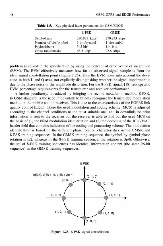
48 GSM, GPRS and EDGE Performance
Table 1.5. Key physical layer parameters for GSM/EDGE
8-PSK GMSK
Symbol rate 270.833 kbps 270.833 kbpsNumber of bits/symbol 3 bits/symbol 1 bit/symbolPayload/burst 342 bits 114 bitsGross rate/timeslot 68.4 kbps 22.8 kbps
problem is solved in the specification by using the concept of error vector of magnitude(EVM). The EVM effectively measures how far an observed signal sample is from theideal signal constellation point (Figure 1.25). Thus the EVM takes into account the devi-ation in both I- and Q-axes, not explicitly distinguishing whether the signal impairment isdue to the phase noise or the amplitude distortion. For the 8-PSK signal, [18] sets specificEVM percentage requirements for the transmitter and receiver performance.
A further peculiarity, introduced by bringing the second modulation method, 8-PSK,to GSM standard, is the need in downlink to blindly recognise the transmitted modulationmethod in the mobile station receiver. This is due to the characteristics of the EGPRS linkquality control (LQC), where the used modulation and coding scheme (MCS) is adjustedaccording to the channel conditions to the most suitable one, and in downlink, no priorinformation is sent to the receiver but the receiver is able to find out the used MCS onthe basis of (1) the blind modulation identification and (2) the decoding of the RLC/MACheader field that contains indication of the coding and puncturing scheme. The modulationidentification is based on the different phase rotation characteristics in the GMSK and8-PSK training sequences. In the GMSK training sequence, the symbol-by-symbol phaserotation is p/2, whereas in the 8-PSK training sequence, the rotation is 3p/8. Otherwise,the set of 8-PSK training sequences has identical information content (the same 26-bitsequence) as the GMSK training sequences.
(0, 0, 1)
(0, 1, 1)(0, 0, 0)
(1, 1, 0)(1, 0, 1)
(d(3k), d(3k + 1), d(3k + 2)) =(0, 1, 0)
(1, 0, 0)
8-PSK
(1, 1, 1)
Figure 1.25. 8-PSK signal constellation

GSM/EDGE Standards Evolution (up to Rel’4) 49
1.5.2 Enhanced General Packet Radio Service (EGPRS)
EGPRS is built on top of GPRS, which is the packet-switched data service of GSM.Examples of typical high bit rate packet services include fast file transfer, Internet serviceaccess, web browsing and remote email.
EGPRS has a major impact on the RF and the physical layer of the radio interface aswell as on RLC/MAC protocol, but the changes to other protocols and protocol layers areminor. The EDGE RF specification and the definition of the burst structures are commonto both EGPRS and ECSD. One large conceptual modification in EGPRS, compared withGPRS, is the link quality control which, in EGPRS, also supports incremental redundancy(type II hybrid ARQ), in addition to GPRS-type link adaptation mode (type I hybrid ARQ).The LQC includes nine different modulation and coding schemes (MCS-1–MCS-9) aswell as related signalling and other procedures for link adaptation (switching betweendifferent MCSs).
Table 1.6 shows the EGPRS modulation and coding schemes (MCS) and their datathroughputs. New GMSK coding schemes (MCS-1–MCS-4), different from GPRS GMSKcoding schemes (CS-1–CS-4), are needed because of the incremental redundancy support.Figure 1.26 illustrates the coding and puncturing principle of the header and payload partof an MCS-9 radio block. In EGPRS radio blocks, the stealing bits indicate the headerformat. The RLC/MAC header is strongly coded (close to rate 1/3 code in 8-PSK modesand close to rate 1/2 code in GMSK modes) to allow reliable decoding of the header inincremental redundancy (IR) operation. There is also a separate header check sequence(HCS) for the error detection in the header part. The RLC data payload is encodedalong with the final block indicator (FBI) and extension bit (E) fields. Also, the blockcheck sequence (BCS) and tail bits (TB) are added before encoding. In the illustratedcase (MCS-9), two RLC data blocks are mapped on one radio block. Note that in thecase of MCS-8 and MCS-9, an RLC data block is interleaved over two bursts only. TheRLC/MAC header is though interleaved over the whole radio block (i.e. four bursts).
EGPRS modulation and coding schemes are organised in families according to theirRLC data block sizes. For example, the MCS-9 carries 1184 payload bits in two RLCdata blocks (592 payload bits in each of them) during one EGPRS radio block of fourconsequent bursts. The MCS-6 carries 592 payload bits in one RLC data block and theMCS-3 carries 296 payload bits within the radio block. The number of payload bits in
Table 1.6. EGPRS modulation and coding schemes
Modulation andcoding scheme
Coderate
Modulation Data rate/timeslot (kbps)
Family
MCS-9 1.0 8-PSK 59.2 AMCS-8 0.92 54.4 AMCS-7 0.76 44.8 BMCS-6 0.49 29.6 AMCS-5 0.37 22.4 BMCS-4 1.0 GMSK 17.6 CMCS-3 0.80 14.8 AMCS-2 0.66 11.2 BMCS-1 0.53 8.8 C

50 GSM, GPRS and EDGE Performance
1392 bits
612 bits 612 bits
Rate 1/3 convolutional coding Rate 1/3 convolutional coding
Puncturing Puncturing
45 bits3 bits
USF BCS TB BCS TBE FBIFBI Data = 592 bits Data = 592 bitsEHCSRLC/MACHdr.
1836 bits 1836 bits135 bits
Puncturing
36 bits
124 bits 612 bits 612 bits 612 bits 612 bits 612 bits 612 bits
P1 P2 P3 P1 P2 P3
36 bitsSB = 8
Figure 1.26. EGPRS coding and puncturing example (MCS-9: uncoded 8-PSK, two RLC blocksper 20 ms) [14]
MCS-6 and MCS-3 being sub-multiples of the higher coding schemes in the same family(family A) enables effective re-transmission of the negatively acknowledged RLC datablocks with the lower coding schemes within the family, if needed. A typical case wherethis functionality is useful is the sudden change in the channel conditions.
The transfer of RLC data blocks in the acknowledged RLC/MAC mode can be con-trolled by a selective type I ARQ mechanism or by type II hybrid ARQ (IR) mechanism,coupled with the numbering of the RLC data blocks within one temporary block flow. Thesending side (the MS or the network) transmits blocks within a window and the receivingside sends packet uplink Ack/Nack or packet downlink Ack/Nack message when needed.
The initial MCS for an RLC block is selected according to the link quality. For the re-transmissions, the same or another MCS from the same family of MCSs can be selected.For example, if MCS-7 is selected for the first transmission of an RLC block, any MCSof the family B can be used for the re-transmissions. The selection of MCS is controlledby the network.
In the EGPRS type II hybrid ARQ scheme, the information is first sent with one ofthe initial code rates (i.e. rate 1/3 encoded data are punctured with PS 1 of the selectedMCS). If the RLC data block is received in error, additional coded bits (i.e. the outputof the rate 1/3 encoded data that is punctured with PS 2 of the prevailing MCS) aresent and decoded together with the already received code words until decoding succeeds.If all the code words (different punctured versions of the encoded data block) havebeen sent, the first code word (which is punctured with PS 1) is sent. Alternatively,it is possible to use incremental redundancy modes called MCS-5–7 and MCS-6–9,in which the initial transmissions are sent with either MCS-5 or MCS-6 (respectively)and the re-transmissions are sent with MCS-7 or MCS-9 (respectively). In the EGPRStype I ARQ, the operation is similar to that of the EGPRS type II hybrid ARQ, exceptthat the decoding of an RLC data block is solely based on the prevailing transmission

GSM/EDGE Standards Evolution (up to Rel’4) 51
(i.e. erroneous blocks are not stored). The motivation for supporting the incrementalredundancy mode is the improved data throughput and the robustness for varying channelconditions and measurement errors. Incremental redundancy is defined to be mandatoryfor the MS and optional for the network.
Another RLC/MAC layer modification in Rel’99 due to EGPRS is the increased RLCwindow size. In GPRS with four-burst radio blocks (20 ms), the RLC window size of 64is defined. With the higher coding schemes of EGPRS, MCS-7 to MCS-9, there are twoRLC blocks per 20 ms radio block, which makes the RLC window size 64 too small andRLC protocol subject to stalling. Therefore, the EGPRS RLC window size was increasedto 128, and a compression method was defined for the acknowledgement bitmap of theRLC blocks (see details in GSM 04.60).
1.5.2.1 Bit Error Probability (BEP) Measurements
In Rel’99, a generic enhancement to the channel quality measurements was alsointroduced. Earlier, the measure to be used for the channel quality indication was theRX QUAL, which is an estimate of the pseudo bit error rate, i.e. computed by comparingthe received bit sequence (before decoding) with the encoded version of the decoded bitsequence and counting the number of bit errors. It was shown in [19] that the alternativemeasure—bit error probability (BEP)—better reflects the channel quality in varyingchannel conditions—including frequency hopping and varying mobile speed. BEP isestimated burst by burst, for example, from the soft output of the receiver. The detailedrealisation of the measurement itself is left for the equipment vendors, whereas the methodof reporting the BEP measurements and the accuracy requirements are standardised. Themeasurements to be reported by the MS for the network are MEAN BEP and CV BEP,where the MEAN BEP is the average of the block wise mean BEP during the reportingperiod and the CV BEP is the average of the blockwise coefficient of variation (CV)(CV = Std(BEP)/Mean(BEP)) during the reporting period.
1.5.2.2 Adjustable Filtering Length for the EGPRS Channel QualityMeasurements
A further standardised means of optimising the EGPRS performance is the filtering lengthof the LQC measurements, which can be varied [20]. The network and the MS cannegotiate with each other—using the radio link control signalling—the optimum lengthof the filter that is used to smooth the BEP measurements that the MS sends to thenetwork. For example, typically the filter length should be shorter for the MS with higherspeed, so that the received channel quality information at the network would be as correctas possible. On the other hand, for slowly moving mobiles, the longer averaging of themeasurements improves the accuracy.
1.5.3 Enhanced Circuit-switched Data (ECSD)ECSD uses current HSCSD as a basis. The user data rates are not increased compared toHSCSD (up to 64 kbps), but these rates can be achieved with smaller numbers of timeslotsand simpler MS implementation. Data rates to be provided with ECSD, although limited to64 kbps, are still sufficient for providing various transparent and non-transparent services.ECSD enables inter-working with audio modems at higher data rates than in current GSM

52 GSM, GPRS and EDGE Performance
Table 1.7. ECSD data rates
Codingscheme
Code rate Modulation Gross rate(kbps)
Radio interfacerate (kbps)
User rates(kbps)
TCH/28.8 (NT/T) 0.419 8-PSK 69.2 29.0 28.8TCH/32.0 (T) 0.462 8-PSK 69.2 32.0 32.0TCH/43.2 (NT) 0.629 8-PSK 69.2 43.5 43.2
networks, inter-working with ISDN at various data rates and various video-based servicesranging from still image transfer to videoconferencing services.
Higher data rates are defined for both transparent and non-transparent services. Radiointerface rates (and user rates per timeslot) for ECSD are shown in Table 1.7. In the defini-tion of the ECSD, only a few new traffic channels are defined. The control channels—boththe common, dedicated and associated control channels—are the same as for the othercircuit-switched services (like, e.g. for the 9.6 kbps circuit-switched data, HSCSD) exceptthe fast associated control channel for the ECSD (FACCH/E), which uses GMSK modu-lation and is interleaved rectangularly on the four consequent TDMA frames. Further, thedetection of the FACCH/E frame is based on the similar principles as the identificationof the 8-PSK and GMSK modulated data blocks in EGPRS, i.e. the modulation methodis blindly detected in the receiver, and if a block of four GMSK bursts is receivedin the middle of the 8-PSK data frames, the receiver knows that an FACCH/E framewas received.
The 28.8-kbps data rate is available for transparent and non-transparent services forboth single and multislot configurations. The 32.0-kbps service is available only in mul-tislot configuration (two-slot) and can be used for offering 64-kbps transparent service,while 43.2 kbps is available for non-transparent services only.
The ECSD architecture is largely based on HSCSD transmission and signalling. Thisensures a minimum impact on existing specifications. The basic principle is to use thesame transcoder and rate adaptation unit (TRAU) frame formats and multiple 16-kbpssub-channels in the network side. For example, 28.8-kbps service provided with oneradio interface timeslot is supported with two 16-kbps sub-channels and 14.4-kbps TRAUframes on the network side.
Figure 1.27 shows the network architecture for providing (a) 57.6-kbps non-transparentservice and (b) 56-/64-kbps transparent service.
ECSD 57.6-kbps non-transparent service is provided using two timeslots of 28.8 kbpsas shown in Figure 1.27(a). The same frame formats as in HSCSD are used end to endbetween the MS/TAF and MSC/IWF. The BTS is responsible for the de-multiplexing ofdata between two radio timeslots and four Abis sub-channels.
The network architecture for supporting bit transparent 56-/64-kbps service is shownin Figure 1.27(b). It is provided using two air interface timeslots of 32 kbps. The rateadaptation functions are located in the BTS.
Higher data rates can be offered with limited coverage and, therefore, the link adapta-tion mechanism becomes essential. Switching between 8-PSK- and GMSK-based channelsis done with the standard intra-cell handover procedure. Signalling for link adaptation isbased on the existing HSCSD signalling mechanism.

GSM/EDGE Standards Evolution (up to Rel’4) 53
(a) 57.6 kbps non-transparent service
57.6 =2 × 28.8 (29.0)
4 × 14.4 4 × 14.4 4 × 14.4
1 × 64 k
MS/TAF BTS BSC TRAU MSC/IWF
(b) 56.0/64.0 kbps transparent service
2 × 32.0 64.0MS/TAF BTS BSC TRAU MSC/IWF
Figure 1.27. Network architecture
1.5.4 Class A Dual Transfer Mode (DTM)With a Class A mobile station, a subscriber can simultaneously connect to the circuit-switched core network (to mobile switching centre (MSC)) and to the packet-switchedcore network (to SGSN), through A and Gb interfaces respectively. Until recently, theimplementation of a Class A MS has been considered impractical and costly—owing tothe uncoordination of the radio resources for the CS and PS connections, which impliesduplicating many key parts of an MS like the transceiver. To enable practical low costimplementation of the Class A mobile, the Class A dual transfer mode (DTM) wasdefined. This functionality was deemed necessary in the Rel’99 specification—at thesame schedule with the first UTRAN standard release (Rel’99) and with the inter-workingbetween GSM and UMTS (e.g. inter-system handovers). This package of specificationsensures that an operator can provide the same type of service—e.g. simultaneous voiceand data—in both radio access networks, GSM and UTRAN.
The DTM concept includes the following:
• The single timeslot method. TCH/H + PDTCH/H. In this method, AMR (adaptivemulti-rate speech codec) voice frames are carried in the half-rate circuit-switched chan-nel (TCH/H) and the user data in the half-rate packet-switched channel (PDTCH/H).The significance of the single timeslot method is that it enables implementation ofthe Class A DTM feature even in single timeslot MSs. Another advantage is that incase of a handover, the availability of the radio resources in the target cell can beeasily guaranteed.
• The multiple timeslot method. TCH + one or more adjacent PDTCH. In this method,one full timeslot is reserved for the AMR voice frames and the adjacent timeslots areused for the user data transfer.
A further significant difference between the single and multiple timeslot methods is that inthe former one, the PDTCH/H resource is always dedicated for the DTM user (dedicated
54 GSM, GPRS and EDGE Performance
mode of (E)GPRS MAC protocol), whereas in the latter one, the PDTCH resources canbe shared (shared mode of (E)GPRS MAC protocol).
More details of Class A DTM can be found, e.g. in [21, 22].
1.5.5 EDGE CompactCompact is a particular mode—or variant—of EGPRS, which is designed for the deploy-ment in the narrow frequency band allocations—the minimum requirement being thedeployment in less than 1 MHz of spectrum. It is known that the capacity (spectral effi-ciency) of the GSM network is limited by the BCCH reuse, and as available bandwidthdecreases, its relative impact will be higher. This is due to the nature of the broadcastcontrol channel concept in the GSM standard, which requires continuous transmissionwith constant transmit power in the beacon frequency (BCCH frequency). This causesthe BCCH frequency reuse to be relatively large to ensure reliable reception of the systeminformation in the broadcast and common control channels.
The key component of the compact mode is the new control channel structure, which isbased on the discontinuous time rotating BCCH, which enables significantly lower reusefactors for the BCCH channel and thus operation in the narrow spectrum allocation. Thecharacteristics of the compact mode are the following:
• It is a stand-alone high-speed packet data system (EGPRS variant with alternativecontrol channel structure).
• It can be deployed in only 600 kHz of spectrum (+ guardband) by using three carriersin a 1/3 reuse pattern.
• It requires inter–base station time synchronisation.
• It uses discontinuous transmission on the control carriers and a new logical controlchannel combination (compact packet broadcast control channel (CPBCCH) based ona standard 52-multiframe). It uses timeslot mapping of control channels in a rotatingfashion, which makes neighbour channel measurements more feasible during traf-fic mode.
More details on compact mode can be found in [23].
1.5.6 GPRS and EGPRS Enhancements in Rel’4In GERAN Rel’4, a few new features are added to the GPRS and EGPRS protocolsand signalling to improve the efficiency of the data transfer with certain typical trafficcharacteristics and the seamlessness of the service in the cell change. These features, thedelayed temporary block flow release and the network-assisted cell change (NACC), areintroduced briefly in the following sections.
1.5.6.1 Extended UL TBF
The early GPRS protocols are inefficient when dealing with the bursty TCP/IP traffic. TheGPRS radio interface protocols are initially designed to free the unused radio resourcesas soon as possible. With bursty IP traffic, this may lead to the frequent set-up and

GSM/EDGE Standards Evolution (up to Rel’4) 55
release of the radio resources (more specifically TBFs), which results in an increasedsignalling load and inefficiency in the data transfer, as the release and set-up of the TBFstakes some time, and radio interface resources. Unnecessary TBF set-ups and releasescan be avoided by delaying the release of the TBF. In DL direction during the inactiveperiod, the connection is maintained by periodically sending dummy LLC frames in thedownlink [20]. This DL enhancement was already introduced in Rel’97 specifications. Itscounterpart in UL direction is called Extended UL TBF as was specified in Rel’4. Inextended UL TBF, the UL TBF may be maintained during inactivity periods (the MSdoes not have more RLC information to send), and the network determines the release ofthe UL TBF.
1.5.6.2 Network-assisted Cell Change
The GPRS cell change was not initially designed for the services that would require seam-less cell change operation, such as real-time services. Later on, these requirements gainedmore importance and a new type of cell change, network-assisted cell change (NACC),was defined. In the NACC, the network can send neighbour cell system information toan MS. The MS can then use this system information when making the initial access to anew cell after the cell change. This way, the MS does not need to spend some time in thenew cell receiving the system information, and the typical break in the ongoing servicedecreases from seconds to a few hundreds of milliseconds [24].
References[1] Kurronen K., Evolution of GSM Towards the Third Generation Requirements, Asian
Institute of Technology (AIT) and Nokia, Hanoi, Vietnam, 25–26, 1997.[2] Pirhonen R., Rautava T., Penttinen J., ‘TDMA Convergence for Packet Data Ser-
vices’, IEEE Personal Commun., 6(3), 1999, 68–73.[3] Jarvinen K., ‘Standardisation of the Adaptive Multi-rate Codec’, Proc. X European
Signal Processing Conference (EUSIPCO), Tampere, Finland, 4–8, 2000.[4] 3GPP TS 05.08 V8.6.0 (2000-09), 3rd Generation Partnership Project; Technical
Specification Group GERAN; Digital Cellular Telecommunications System (Phase2+); Radio Subsystem Link Control (Release 1999).
[5] 3GPP TS 05.02 V8.10.0 (2001-08), 3rd Generation Partnership Project; TechnicalSpecification Group GSM/EDGE Radio Access Network; Digital Cellular Telecom-munications System (Phase 2+); Multiplexing and Multiple Access on the RadioPath (Release 1999).
[6] 3GPP TS 05.04, Modulation, 3rd Generation Partnership Project; Technical Speci-fication Group GERAN.
[7] GSM 05.05 Version 8.8.0 Release 1999: Digital Cellular Telecommunications Sys-tem (Phase 2+); Radio Transmission and Reception.
[8] GSM 05.03 Version 8.11.0 Release 1999: Digital Cellular TelecommunicationsSystem (Phase 2+); Channel Coding.
[9] 3GPP TS 05.10, Radio Subsystem Synchronisation, 3rd Generation PartnershipProject; Technical Specification Group GERAN.
[10] 3GPP TS 04.64, LLC Specification GPRS, 3rd Generation Partnership Project;Technical Specification Group GERAN.

56 GSM, GPRS and EDGE Performance
[11] 3GPP TS 04.65, GPRS Subnetwork Dependent Convergence Protocol (SNDCP),3rd Generation Partnership Project; Technical Specification Group GERAN.
[12] 3GPP TS 48.018, General Packet Radio Service (GPRS); Base Station System(BSS)—Serving GPRS Support Node (SGSN); BSS GPRS Protocol, 3rd Genera-tion Partnership Project; Technical Specification Group GERAN.
[13] 3GPP TS 09.60, GPRS Tunnelling Protocol (GTP) across the Gn and Gp Interface,3rd Generation Partnership Project; Technical Specification Group GERAN.
[14] 3GPP TS 03.64, General Packet Radio Service (GPRS); Overall Description ofthe GPRS Radio Interface; Stage 2, 3rd Generation Partnership Project; TechnicalSpecification Group GERAN.
[15] 3GPP TS 03.60, GPRS Stage 2, 3rd Generation Partnership Project; TechnicalSpecification Group GERAN.
[16] 3GPP TS 04.07, Mobile Radio Interface Signalling Layer 3—General Aspects, 3rdGeneration Partnership Project; Technical Specification Group GERAN.
[17] GSM 04.60 V8.1.0 (1999-11), European Standard (Telecommunications Series),Digital Cellular Telecommunications System (Phase 2+); General Packet RadioService (GPRS); Mobile Station (MS)–Base Station System (BSS) Interface; RadioLink Control/Medium Access Control (RLC/MAC) Protocol (GSM 04.60 Version8.1.0 Release 1999).
[18] 3GPP TS 45.005, Radio Transmission and Reception, 3rd Generation PartnershipProject; Technical Specification Group GERAN.
[19] Tdoc SMG2, 464/99, Link Quality Control Measurements for EGPRS , Dublin, Ire-land, April 12–16, 1999.
[20] 3GPP TS 44.060, General Packet Radio Service (GPRS); Mobile Station(MS)–Base Station System (BSS) Interface; Radio Link Control/Medium AccessControl (RLC/MAC) Protocol, Radio Resource Control Protocol, 3rd GenerationPartnership Project; Technical Specification Group GERAN.
[21] 3GPP TS 43.055, Dual Transfer Mode, 3rd Generation Partnership Project; Tech-nical Specification Group GERAN.
[22] Pecen M., Howell A., ‘Simultaneous Voice and Data Operation for GPRS/EDGE:Class A Dual Transfer Mode’, IEEE Personal Commun., 8, 2001, 14–29.
[23] ETSI SMG2 Tdoc 1549/99, Concept Proposal for EGPRS-136, Revision 1.6.[24] 3GPP TSG GERAN #3 GP-010361 Network Assisted Cell Change; Concept
Document.